EonStor DS 4024 - NAS Infortrend - Free user manual and instructions
Find the device manual for free EonStor DS 4024 Infortrend in PDF.


User questions about EonStor DS 4024 Infortrend
0 question about this device. Answer the ones you know or ask your own.
Ask a new question about this device
Download the instructions for your NAS in PDF format for free! Find your manual EonStor DS 4024 - Infortrend and take your electronic device back in hand. On this page are published all the documents necessary for the use of your device. EonStor DS 4024 by Infortrend.
USER MANUAL EonStor DS 4024 Infortrend
Infortrend EonStor DS 4000 Series
Hardware Manual
Legal Information
All Infortrend products, including the product customers have purchased from Infortrend, shall be subject to the latest Standard Warranty Policy available on the Infortrend website: http://www.infortrend.com/global/Support/Warranty
Infortrend may from time to time modify, update or upgrade the software, firmware or any accompanying user documentation without any prior notice. Infortrend will provide access to these new software, firmware or documentation releases from certain download sections of our website or through our service partners. Customer shall be responsible for maintaining updated version of the software, firmware or other documentation by downloading or obtaining from Infortrend, and installing designated updated code, including but not limited to firmware, microcode, basic input/out system code, utility programs, device drivers, and diagnostics delivered with Infortrend product.
Before installing any software, applications or components provided by a third party, customer should ensure that they are compatible and interoperable with Infortrend product by checking in advance with Infortrend. Customer is solely responsible for ensuring the compatibility and interoperability of the third party's products with Infortrend product. Customer is further solely responsible for ensuring its systems, software, and data are adequately backed up as a precaution against possible failures, alternation, or loss.
For any questions of hardware/ software compatibility, and the update/ upgrade code, customer should contact Infortrend sales representative or technical support for assistance.
To the extent permitted by applicable laws, Infortrend shall NOT be responsible for any interoperability or compatibility issues that may arise when (1) products, software, or options not certified and supported by Infortrend are used; (2) configurations not certified and supported by Infortrend are used; (3) parts intended for one system are installed in another system of different make or model.
Contact Information
Worldwide offices
To contact one of our world wide offices visit the following web site:
Contact Infortrend
Customer Support
Contact your system vendor or visit the following support site:
EonStor DS Support
Copyright Notice
All rights reserved. This publication may not be reproduced, transmitted, transcribed, stored in a retrieval system, or translated into any language or computer language, in any form or by any means, electronic, mechanical, magnetic, optical, chemical, manual or otherwise, without the prior written consent of Infortrend Technology, Inc.
Disclaimer
Infortrend Technology makes no representations or warranties with respect to the contents hereof and specifically disclaims any implied warranties of merchantability or fitness for any particular purpose. Furthermore, Infortrend Technology reserves the right to revise this publication and to make changes from time to time in the content hereof without obligation to notify any person of such revisions or changes. Product specifications are also subject to change without prior notice.
Trademarks
Infortrend, the Infortrend logo, EonOne, SANWatch, ESVA, EonStor DS, EonStor GS, EonNAS, and EonPath are registered trademarks of Infortrend Technology, Inc. Other names prefixed with "IFT" and "ES" are trademarks of Infortrend Technology, Inc.
- Windows is a registered trademark of Microsoft Corporation.
• Mac OS X is a registered trademark of Apple Computer, Inc.
• Linux is a trademark of Linus Torvalds.
All other names, brands, products or services are trademarks or registered trademarks of their respective owners.
Safety Precautions
Read these instructions carefully before you install, operate, or transport the EonStor DS Storage System system and JBODs.
Energy Hazards Precaution
This equipment is intended to be used in Restrict Access Location, like computer room. The access can only be gained by SERVICE PERSONS or by USERS who have been instructed about the metal chassis of the equipment is have energy hazards that service persons have to pay special attention or take special protection before touching it. Further, the access is through the use of key or security identity system. Only authorized by well trained professional person can access the restrict access location.
Installation and Operation
- Install the rack cabinet and the associated equipment at a site where the ambient temperature (special room cooling equipment may be required) stays lower than:
a. 35^ \~ if your system have a BBU
b. 40^ \~ if your system does not have a BBU
• Install the power source socket outlet near the enclosure where it is easily accessible and ground the rack cabinet.
- Secure airflow clearance inside and around the rack cabinet.
- Secure an 18 to 20cm clearance on the rear side.
- Do not cover the enclosure openings.
- Route the cables inside the rack cabinet.
- Do not leave drive bays empty as it will affect airflow efficiency.
- Secure each enclosure module using its retaining screws.
- Place power cords and other cables away from foot traffic. Do not place items on top of power cords and make sure they do not rest against data cables.
• Install all modules to the enclosure before powering-on systems.
- Ensure that the correct power range is being used before powering-on.
- DO NOT remove covers or replaceable modules if they are not faulty.
- If the system is not going to be used for a long period of time, disconnect it from the power mains to avoid transient over-voltage.
- For power source redundancy, please make sure that the two PSUs are plugged into two different power sources (i.e. Different circuit breakers).
Service and Maintenance
- Keep the faulty module in place until you have a replacement unit; an empty module greatly affects the airflow efficiency within the enclosure.
- During service operation, place the enclosure on soft and clean surface to prevent exterior damage. Do not place tools or other items on top.
- When transporting the enclosure, repackage all disk drives separately in the original package foam blocks. Replaceable modules can stay in the enclosure if you are using the original package; if not, repackage them separately as well.
- Disconnect the power cords before servicing or cleaning the enclosure.
- Use a slightly moistened paper sheet or cloth for cleaning. Avoid using liquid or sprayed detergent.
- When replacing components, insert them as gently as possible while assuring full engagement. Vibration and shock can easily damage hard drives.
- Only qualified service personnel should open the enclosure.
- Contact service personnel if any of the following situations occurs:
- The power cord or plug is damaged.
- The enclosure has been exposed to moisture.
- The system has not been working properly.
- The enclosure was dropped against a hard surface.
- The enclosure shows obvious signs of breakage.
- To move the enclosure, more than one person might be necessary due to its weight. Drives should be removed from the enclosure beforehand.
Important Notice
The use of Infortrend certified components is strongly recommended to ensure compatibility, quality and normal operation with your Infortrend products. Please contact your distributor for a list of Infortrend certified components (e.g. SFP, SFP+, HBA card, iSCSI cable, FC cable, memory module, etc.).
ESD Precautions
- Handle the modules by their retention screws, ejector levers, or the module's metal frame/faceplate only. Avoid touching the PCB boards or connector pins.
- Use a grounded wrist strap and an anti-static work pad to discharge static electricity when installing or operating the enclosure.
- Avoid dust, debris, carpets, plastic, vinyl, and Styrofoam in your work area.
- Do not remove any module or component from its anti-static bag before installation takes place.
- Drives must not be stacked on top of each other without their protective drive trays. Even when drives are fixed in the drive trays, contacting the exposed PCB or rear-side interface may damage the drives.
About This Manual
The manual introduces hardware components of EonStor DS 4000 series and JBOD systems.
It also describes how to install, monitor, and maintain them.
For non-serviceable components, please contact our support sites.
Firmware operation: Consult the Firmware User Manual on the CD-ROM.
SANWatch software: Consult the SANWatch User Manual on the CD-ROM.
Revision History
| Version | Date | Description |
| 1.0 | Apr. 2017 | Initial release |
| 1.1 | May 2017 | Models revised |
| 1.7 | Oct 2017 | Revised |
| 1.8 | Nov 2017 | Models revised |
Table of Contents
Legal Information 2
Contact Information.... 3
Copyright Notice....4
Safety Precautions 5
Energy Hazards Precaution....5
Installation and Operation....5
Service and Maintenance....6
Important Notice ....7
ESD Precautions 7
About This Manual 8
Revision History......8
Table of Contents 9
Introduction 15
Product Overview 15
Model Naming Conventions.... 15
Model Variations 16
Major Components ....17
Controller and Interface 17
JBOD Controller and Interface.... 17
Power supply unit with built-in cooling module.... 18
The Rear Panel 19
Dual-Controller Models 19
Single-Controller Models 21
Upgrading Single-Controller to Dual-Controller System 21
Connection between Storage System System and JBOD.... 21
Chassis....22
Front Panel....22
Rear Panel 24
Internal Backplane 26
Front Panel Components....27
LED Panel 27
Drive Tray Bezel 28
Rear Panel Components ......29
Controller Module of Storage System Systems.... 29
Controller Module of JBOD enclosures.... 31
Super Capacitor & Flash Backup Module 32
PSU & Cooling Module 33
System Monitoring Features....34
Expansion Enclosure Support.... 34
JBOD Enclosure Status Monitoring: 35
I^2C bus.... 35
Firmware (FW) and SANWatch.... 35
Audible Alarms.... 35
Hot-swapping....36
Hardware Installation 37
Installation Prerequisites....37
Installation Procedures Overview 38
Unpacking the System....39
Box contents.... 39
Preinstalled Components.... 39
Components to be Installed 39
Installing Hard Drives....40
Hard Drive Installation Prerequisites.... 40
SAS Interface 42
Hard Drive Designation.... 43
Installing the Hard Drive into Drive Tray.... 44
Installing the Hard Drive Tray into the Enclosure 45
Installing Host Boards....46
Removing the Controller 48
Installing the Controller 48
System Connection 49
General Considerations on Making Connections....49
Host-Side Topologies....50
Host-Side Parameters 50
Maximum Concurrent Host LUN Connection ("Nexus" in SCSI).... 51
Maximum Queued I/O Count 51
Fibre-Host Connections....52
Fibre-Host Topologies.... 54
Fibre Cabling 55
Simple End-to-End Connection.... 56
DAS (Direct-Attached) Connection 57
Switched Fabric Connection (Dual-Controller) 59
Switched Fabric Connection (Single-Controller).... 61
SAS-Host Connections....63
DAS (Direct-Attached Storage) Connection with Redundant Host Path ..... 64
DAS (Direct-Attached Storage) Connection to Two Servers.... 66
Ethernet-Host Connections....67
Network & Host Connection Topologies 68
High Availability IP SAN with Redundant Controller 69
Single-Controller with Fault-Tolerant Path.... 71
High Availability IP SAN (Recommended for Remote Replication)....72
High Availability IP SAN with Port Trunk (Remote Replication Enabled) .... 74
Hybrid Host Connections....76
Single Hybrid Unit Connected to FC/iSCSI Hosts 76
Utilizing Hybrid iSCSI ports for Data Replication.... 77
JBOD Connections....78
JBOD SAS Expansion Configuration 78
Configuration Rules 79
Dual-Controller Expansion Connection 81
Single-Controller Expansion Connection.... 83
Management Console Connections....85
Connecting Storage System System to external consoles 86
Power Connections....87
Checklist....87
Power Cords Connections 87
Power On Procedure 88
Power On Status Check 89
Power Off Procedure 90
System Monitoring 91
Monitoring Features....91
LED Panel 92
Drive Tray LED 94
Storage System System Controller LEDs....95
1G iSCSI/Ethernet Management Port LEDs 99
12G SAS Expansion Port LEDs....100
10G Ethernet Host Board Port LEDs 101
10G iSCSI Host Board Port LEDs (RJ-45)....102
10G iSCSI Host Board Port LEDs (Fibre)....103
40G iSCSI Host Board Port LED's 104
16G Fibre Channel Host Board Port LEDs 105
8G Fibre Channel Host Board Port LEDs 106
SFP+ On-Board and Converged Host Board Port LED's 107
InfiniBand Host Board Port LED's 108
12G SAS Host Board LED....109
Controller LED for 12G SAS JBOD Models.... 110
PSU & Built-in Cooling Module LEDs 111
Alarms and I2C Bus.... 112
Audible Alarms....112
I^2C 112
System Maintenance.... 113
Restoring Default System Settings 114
Restoring Default Settings 114
Replacing the Storage System System Controller Module(s).... 116
Replacing the Host Board....118
Replacing Memory Module(s).... 119
Replacing the Cache Backup Module (CBM) 120
Supercapacitor Fault Conditions and Precautions 120
Replacing the Supercapacitor.... 121
Replacing Flash Backup Module (coupled with Supercapacitor).... 123
Replacing the Power Supply / Cooling Module....124
Detecting a Failed PSU 124
Replacing Power Supply Unit 125
Replacing a Hard Drive....127
Appendix 130
Technical Specifications....130
Host Board Interface.... 130
Power Supply 131
Dimensions.... 132
Environment 133
Certifications....134
Summary 134
Slide Rail Kit Installation Guide 136
Slide Rail Kits 136
Enclosure Installation Prerequisites....136
Unpacking the System....137
Component Installation Procedure 137
Tools Required....137
Rackmount Slide Rail Kits 138
Rack Ear Mount Kit....138
Kit Contents.... 138
Installation Procedure.... 139
Slide Rail Kit 141
Kit Contents.... 141
Installation Procedure.... 142
Once Mounted....145
Safety Reminders 145
Introduction
Product Overview
This manual introduces EonStor DS 4000 systems that support 12Gbps SAS hard drives. The enclosure is designed to utilize 2.5" or 3.5" hard drives. Drive capacity can be expanded by attaching expansion hard drive enclosures (JBODs).
Model Naming Conventions
The naming rules for Storage System and JBOD models are explained in the example below:
Storage System System:
$$ D S 4 0 2 4 R U B \rightarrow D S ^ {(A)} + 4 0 ^ {(B)} + 2 4 ^ {(C)} + R ^ {(D)} + U ^ {(E)} + B ^ {(F)} $$
| Designation | Description |
| (A) | DS = EonStor DS systemsJB = JBOD systems |
| (B) | 40where 0 indicates first generation,1 indicates second generation and so on |
| (C) | 16 = 3U system, 16 hard drives capable24 = 2U system, 24 hard drives capable |
| (D) | R = redundant (dual) controllersS = single and upgradeable to dual controllersG = single and NOT upgradeable to dual controllers |
| (E) | U = Ultra performance (high IOPS) |
| (F) | B = 2.5" hard drive form factor system3.5" hard drive form factor system if not mentioned |
Model Variations
Comprised of Storage Systems and JBOD models, Storage Systems store hard drives and control the entire storage array while JBOD systems connect to a master Storage System and allow storage capacity expansion by adding more hard drives. Hard drive limitation(s) may vary model to model.
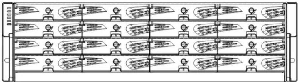
text_image
Diagram of a multi-chamber server rack with labeled buttons and icons for function callouts.EonStor DS 4016 / 4016U models

natural_image
Front view of a rack-mounted server rack with multiple drive bays and indicator lights (no visible text or labels)EonStor DS 4024B / 4024UB models
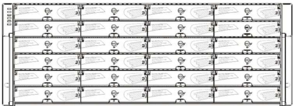
text_image
Diagram of a multi-level storage rack with labeled panels and indicator lights, showing data flow or routing layout.EonStor DS 4024 model
Major Components

NOTE
Upon receiving your system, check the package contents against the included Unpacking List. If module(s) are missing, please contact your system vendor immediately.
Controller and Interface
Each controller comes with pre-installed DIMM module(s).
The traditional battery backup is replaced by an innovative Cache Backup Module methodology (CBM) which consists of a super capacitor and a flash backup module (FBM). Cached data is quickly distributed to a flash backup module for permanent storage with the support of the super capacitor in the event of a power outage. The advantage of a super capacitor is its very fast charging time. The super capacitor is charged within a few minutes and available to distribute power to the controller. So cached data can be saved immediately and permanently in flash backup module (FBM).
The embedded firmware features intelligent algorithms, such as power-saving modes, variable fan speeds, and exiled drive handling, making this model a greener choice.
JBOD Controller and Interface
The enclosure is managed by expander controllers that distribute data flow to individual disk drives and report operating status through a proprietary enclosure service via in-band protocols. The enclosure, along with other JBODs, connects to a Storage System system and serves as a building block of a scalable configuration.
In terms of supported protocols, the firmware supports communications with enclosure devices, SAS/SATA disk drives and as Storage System system featuring SAS expansion ports.
In terms of physical connection, the SAS interface provides ease of cabling through Mini-SAS connectors. With a backplane adapting SAS or SATA drives, the system supports enterprise-class SAS, Near-line SAS, cost-effective SATA-II or SATA-III hard drives or SSDs, and is ideal for adding large capacity to a storage pool.
Power supply unit with built-in cooling module
Cooling module is built into the power supply unit (PSU) to protect the system from overheating. The two hot-swappable PSUs provide constant power to the system. The modular nature of the system and the easy accessibility to all major components ensure ease of maintenance.
The Rear Panel
Dual-Controller Models
Dual-Controller systems are indicated by an “R” in their model number (please refer to Model Naming Conventions). Controller A is located on top and controller B at the bottom for all models. If one controller fails, the second controller module will take over in a manner that is transparent to application servers.
4016 / 4024 / 4024B models:

text_image
A B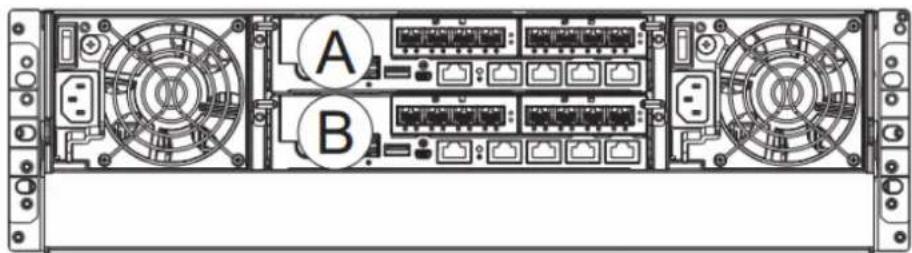
text_image
A B4016U / 4024UB models:
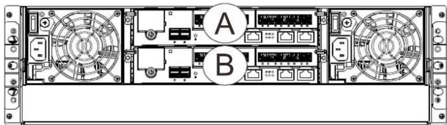
text_image
A BThe top controller (Controller A) is the primary controller. The bottom controller (Controller B) is the secondary (= redundant) controller which is idle during normal operation and takes over the management role when Controller A cannot function properly due to hardware error, controller module removal, etc.
If the failed Controller A restarts or a replacement is installed, Controller A will temporarily assume the role of the secondary controller.
When the Storage System system is rebooted, all system configurations will revert back to the default state and Controller B returns the primary role to Controller A.
Single-Controller Models
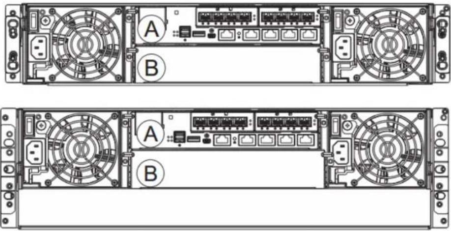
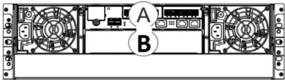
Single-Controller (A) models are designated by a "G" or "S" in their model number. The second controller slot is filled with a dummy cage (B).
4016 / 4024 / 4024B models:
text_image
Technical diagram of a server rack with labeled components A and B, showing front and rear views of internal hardware layout.4016U / 4024UB models:
text_image
A BUpgrading Single-Controller to Dual-Controller System
If the model name of a Single-Controller Storage System System / JBOD is designated with the letter "S", it can be upgraded into a Dual-Controller configuration by adding another controller module and firmware upgrade (see software manual). If the model name is designated with a "G", it is not upgradeable to a Dual-Controller configuration.
For details, please contact your vendor.
Connection between Storage System System and JBOD
The following rule applies when connecting Storage System System and JBOD(s):
- Dual-Controller Storage System system connects to Dual-Controller JBOD.
- Single-Controller Storage System System connects to Single-Controller JBOD.
Chassis
The chassis is rugged constructed and divided into front and rear sections. The chassis is designed to be installed into a rack or cabinet.
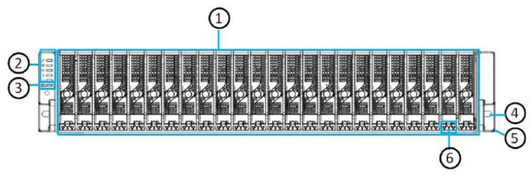
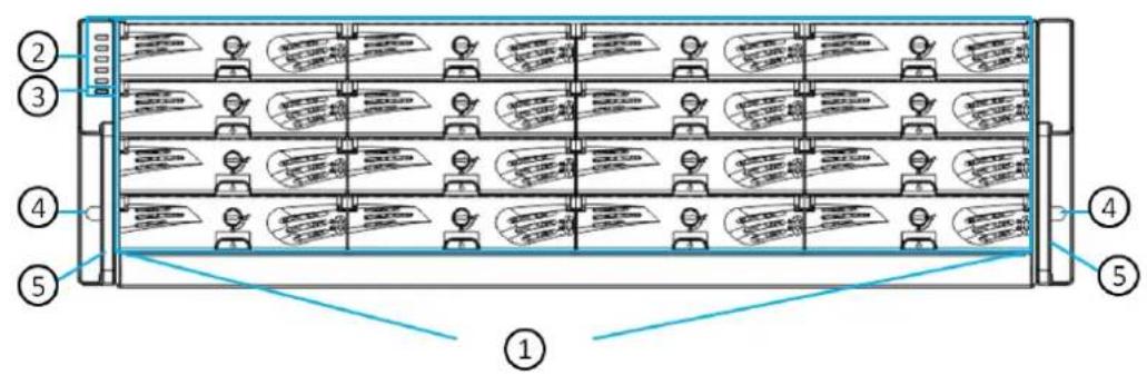
Front Panel
text_image
Diagram of a rack-mounted server or memory unit with numbered components labeled 1 through 6.2U models
text_image
Diagram of a rack-mounted server rack with numbered components and labeled speech bubbles indicating message or status.3U models
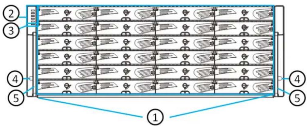
text_image
Diagram of a rack-mounted server rack with numbered components and labeled connectors4U models
- Hard drive trays (1): Each drive tray is hot-swappable and holds a 2.5 / 3.5-inch hard drive.
• LED Panel (2): It contains Service / Power / Cooling Fan / Thermal / System LED - Mute button / service LED (3): The mute button is to mute an alarm when sound or to indicate that the system requires service.
- Handles (4): There are handles on both sides of the enclosure for users to pull / push the enclosure out and into the cabinet when the enclosure is installed on a slide rail rackmount system.
- Rackmount holes (5): There are two rackmount holes (one on each side of the enclosure) for users to secure the enclosure onto the cabinet.
- Hard drive status LED (6): There is a set of hard drive status LEDs on each hard drive tray or right hand side or below of it to indicate operation status.
Rear Panel
4016 / 4024 / 4024B models:
| # | Description | # | Description |
| 1 | Controller A | 3 | Power supply incl. cooling module |
| 2 | Controller B | ||
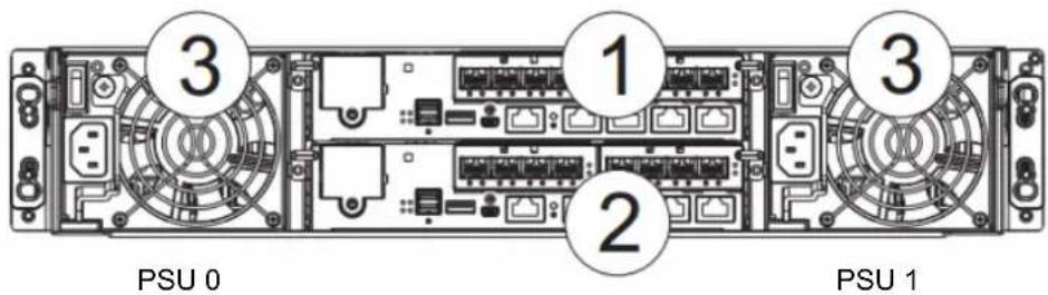
text_image
PSU 0 1 2 3 PSU 1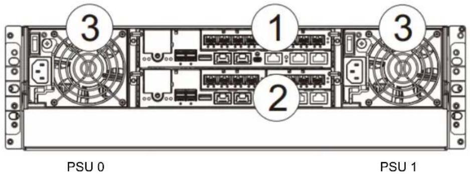
text_image
PSU 0 1 2 3 3 PSU 1- Controllers (1) / (2): Each controller module contains a main circuit board and a pre-installed DIMM module. For Single-Controllers, a dummy cage will be placed at the controller (2) position. The host port configurations will vary. For details, see Rear Panel Components.
- PSU (3): The hot-swappable PSUs provide power to the system. There is a cooling module within each PSU.
• Each power supply contains the following fans:
| PSU Fan | PSU 0 | PSU 1 |
| System fan IDs | 0 & 1 | 2 & 3 |
Please refer to your specific system for details shown in the later sections of this chapter.
4016U / 4024UB models:
| # | Description | # | Description |
| 1 | Controller A | 3 | Power supply + cooling module |
| 2 | Controller B or dummy cage | ||
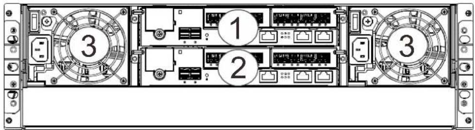
text_image
Diagram of a server rack with labeled components, showing front, rear, and internal layout with numbered slots.
WARNING
Do NOT remove the dummy cage for the Single-Controller model. Doing so will disrupt the internal airflow.
Internal Backplane
An integrated backplane separates the front and rear sections of the chassis. This circuit board provides logic level signals and low voltage power paths. Thermal sensors and I ^2 C devices are embedded to detect system temperatures and PSU/cooling module operating status. This board contains no user-serviceable components.

WARNING
Accessing the backplane board may lead to fatal damage of the system. Also, physical contact with the backplane board may cause electrical hazards.
Front Panel Components
LED Panel
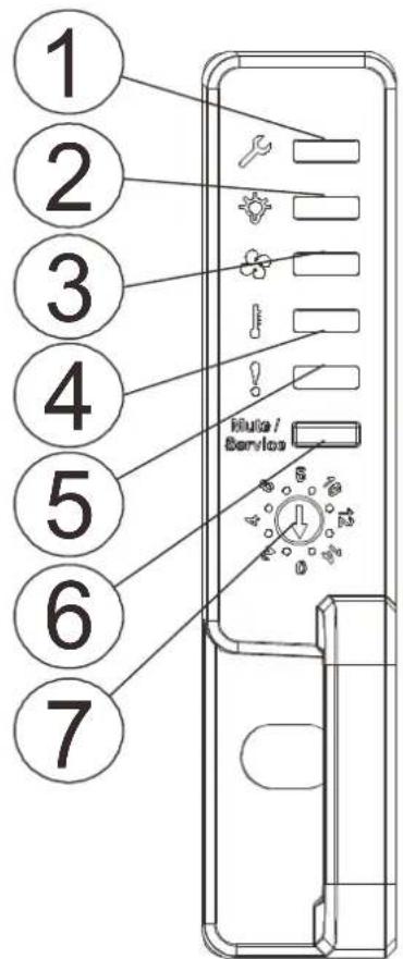
text_image
1 2 3 4 5 6 7 Muto / ServiceThe LED panel can be located on the chassis ear. The LED panel contains Service LED (1), a power supply status LED (2), cooling module status LED (3), temperature sensor status LED (4), System fault LED (5), Mute Service button (6), rotary ID switch (for JBOD) (7). For details, please refer to LED Panel.

WARNING
If critical faults are indicated on the LED panel, verify the cause of the problem as soon as possible and contact your system vendor and arrange for a replacement module.
Drive Tray Bezel
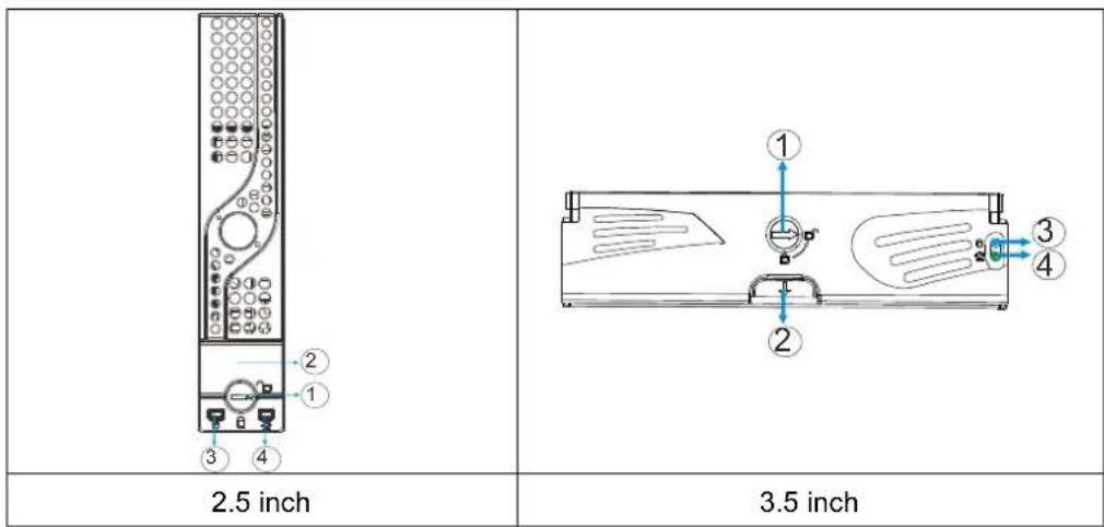
text_image
2.5 inch 3.5 inchThe drive tray is designed to accommodate separately purchased SAS or SATA interface hard disk drives. There is a rotary bezel lock (1) that secures the drive tray in chassis, while a release button (2) can be used when retrieving disk drives from the chassis. To the right of the bezel plate, there is a drive busy LED (3) and a power status LED (4).

WARNING
Be careful not to warp, twist, or contort the drive tray in any way (e.g., by dropping it or resting heavy objects on it). If the drive bay structure is deformed or altered, the drive trays may not fit into the drive bay.
Rear Panel Components
Controller Module of Storage System Systems
| Designation | Description | Designation | Description |
| 1 | Host ports | 6 | Controller status LED |
| 2 | Super capacitor | 7 | Management port |
| 3 | SAS expansion port | 8 | Mini USB port (console port) |
| 4 | Restore default button | 9 | USB Service port |
| 5 | Restore default LED | ||
4016 / 4024 / 4024B models:
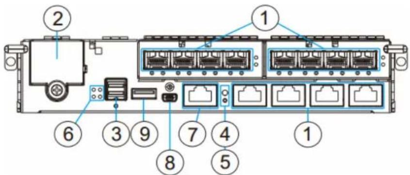
text_image
Diagram of a rack-mounted server with numbered components for identification4016U / 4024UB models:
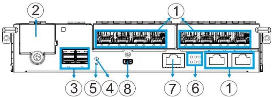
text_image
Diagram of a rack-mounted server rack with numbered components and labeled portsThe controller also features a Cache Backup Module (CBM), consisting of a super capacitor and a Flash Backup Module (FBM).

NOTE
The management port supports 100Mbs and 1000Mbs (1Gbs) speeds.
Host boards are optional add-on components! There are two host board slots, if you are installing a host board for the first time, please install it to the slot on the left (next to SAS exp. Ports).

WARNING
The only time you should remove the controller is to install/ replace the CBM or a failed controller. The controller is built of sensitive components and unnecessary tampering may damage the controller.
Controller Module of JBOD enclosures
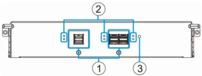
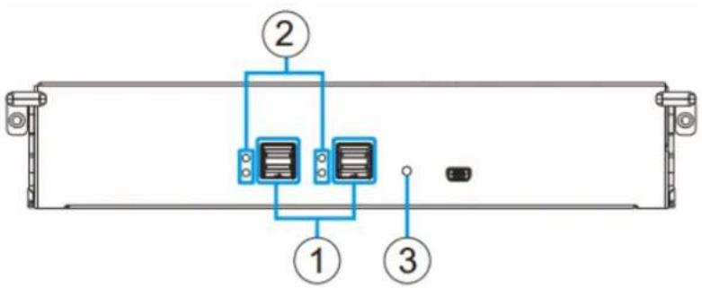
The expansion controller contains a circuit board within a metal canister, interfaced through hot-swap docking connectors at the back-end. Three SAS wide ports on the interface faceplate connect to a managing Storage System System or other JBODs.
flowchart
graph TD
    A["Control Unit 1"] --> B["Component 2"]
    C["Control Unit 2"] --> D["Component 3"]
    B --> E["Return Line"]
    D --> E
    style A fill:#f9f,stroke:#333
    style C fill:#bbf,stroke:#333
    style B fill:#dfd,stroke:#333
    style D fill:#dfd,stroke:#333
text_image
Diagram of a server rack with labeled components including two connected devices and a terminal block| Designation | Description |
| 1 | SAS expansion ports |
| 2 | SAS expansion port Status LED |
| 3 | Controller Status LED |

WARNING
The only time you should remove the controller is to replace a failed controller. The controller is built of sensitive components and unnecessary tampering can damage the controller.
Super Capacitor & Flash Backup Module
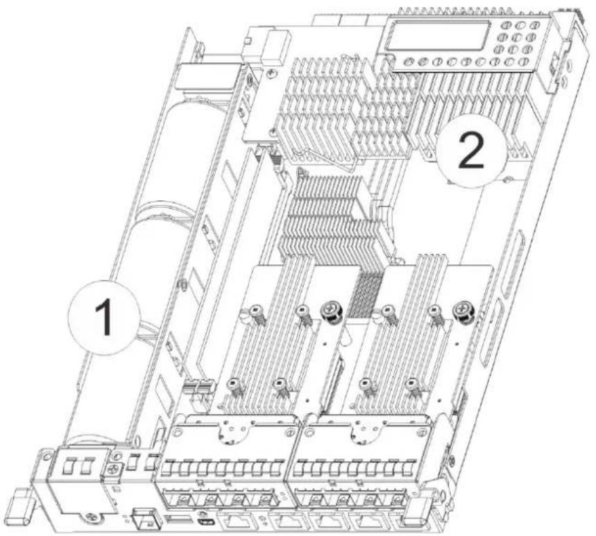
The super capacitor (1) and flash backup module (2) can be located inside the controller and serves as a Cache Backup Module (CBM). With the super capacitor, the cached data can be stored permanently in the flash backup module, in case of a power outage.
text_image
Technical diagram of an electronic device with numbered annotations indicating components for installation or maintenance.
NOTE
The super capacitor is only charged partially when shipped. Therefore, after powering on the system, the super capacitor will start charging to its full capacity. The super capacitor will be charged within a few minutes. If the super capacitor is not charged, there may be a problem with the super capacitor and you should contact your system vendor immediately. You can also check the status of the super capacitor module via SANWatch or the firmware (please refer to respective manuals).
PSU & Cooling Module
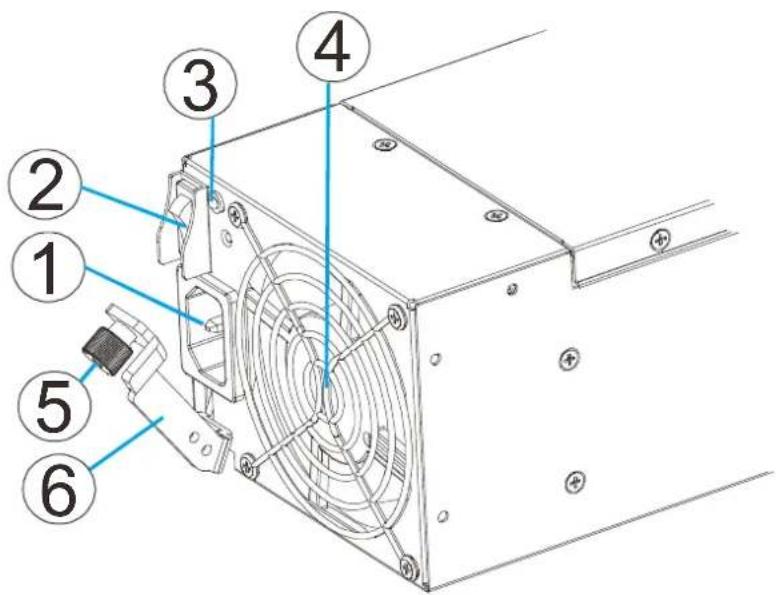
The two redundant, hot-swappable PSUs have a power socket (1), power switch (2), PSU status LED (3), cooling module (4), retention screw (5) and an extraction handle (6).
text_image
Technical diagram of a computer drive with numbered components for identificationThe cooling modules can operate at three rotation speed settings. Under normal operating conditions, the cooling fans run at the low speed. Under the following conditions, cooling fans raise their rotation speed to increase the airflow:
- Component failure: if a cooling module, PSU, or a temperature sensor fails.
- Elevated temperature: if the temperature breaches the upper threshold set for any of the interior temperature sensors.
- During the system initialization stage, the cooling fans operate at high speed and return to low speed once the initialization process has completed and no erroneous condition detected.

NOTE
There are two upper temperature thresholds: one for event notification and the other for triggering higher fan rotation speed. The preset-value for event notification can be changed using the firmware-embedded configuration utility, while the fan speed trigger cannot be changed. Refer to the Firmware Operation Manual for details.
System Monitoring Features
There are a number of monitoring approaches that provide the operating status of individual components.
Expansion Enclosure Support
Monitoring:
A managing Storage System system is aware of the status of JBOD components including those of:
- Expander controller (presence, voltage and thermal readings)
- PSU
- Cooling module
• Enclosure thermal sensor
• Service (the Service signal to specify a specific enclosure) - Disk drives
JBOD Identifier:
The managing Storage System system will sound the alarm and deliver warning messages if there is a conflict between JBOD IDs.
If more than one JBOD is connected to the managing Storage System system, each JBOD needs a unique enclosure ID set using the rotary switch on the LED panel. For example, the firmware automatically disconnects the second JBOD if it is connected online and comes with an ID identical to that of the first JBOD.

NOTE
The IDs for JBODs are #1 to #15. For details, please refer to JBOD connections.
Cooling Module Speed Adjustment:
If any of the detected temperature readings breaches the temperature threshold, the firmware running on the managing Storage System system automatically raises the rotation speed of all cooling fans.
JBOD Enclosure Status Monitoring:
A Storage System system, when connected with expansion JBODs, acquires the component status within other enclosures via a proprietary enclosure monitoring service using the in-band connectivity. No additional management connection is required.
I²C bus
The detection circuitry and temperature sensors are interfaced through a non-user-serviceable I ^2 C bus. When JBODs are attached to controllers, JBOD component status is reported through in-band protocols over expansion links that is managed by a proprietary enclosure service.
Firmware (FW) and SANWatch
The firmware (FW) is preloaded and is used to configure the system. The FW can be accessed through SANWatch, a browser-based graphical user interface (GUI) software that can be installed on a local/remote computer and accessed via the network. The manager communicates with the array via the connection of the existing host links or the Ethernet link to the array's Ethernet port.
Audible Alarms
The system comes with audible alarms that are triggered when certain active components fail or when certain controller or system thresholds are exceeded. Whenever you hear an audible alarm, it is imperative that you determine the cause and rectify the problem immediately.
Event notification messages indicate the completion or status of array configuration tasks and are always accompanied by two or three successive and prolonged beeps. The alarm can be turned off using the mute button on the front panel.

WARNING
Failing to respond when an audible alarm is heard can lead to permanent damage(s) to the system. When an audible alarm is heard, rectify the problem as soon as possible.
Hot-swapping
The system comes with a number of hot-swappable components that can be exchanged while the system is still online without affecting the operational integrity. These components should only be removed from the system when they have to be replaced.
The following components can be user-maintained and hot-swappable:
- Controller module (Dual-Controller models)
• PSU (including cooling modules) - Hard drive

NOTE
Normalized airflow ensures sufficient cooling of the system and is only attained when all components are properly installed. Therefore, a failed component should only be removed when a replacement is available. For instructions on how to replace these hot-swappable components, please refer to System Maintenance.
Hardware Installation
This chapter describes how to install modular components, such as hard drives into the enclosure and CMB into Storage System controller enclosure.

NOTE
Installation into a rack or cabinet should occur BEFORE hard drives are installed into the system.
Installation Prerequisites
Static-free installation environment: The system must be installed in a static-free environment to minimize the possibility of electrostatic discharge (ESD) damage.
Component check: Before installing the system, check to see that you have received all the required components using the Unpacking List included in the package. If there are item(s) missing or appear damaged, contact your vendor for a replacement.
Hard drives: SAS hard drives must be purchased separately and be available prior to installing the system.
Cabling: All the cables that connect the system to the hosts must be purchased separately. Please refer to System Connection for sample topologies and configuration options. Contact your vendor for the list of compatible cables.
Memory modules: If you wish to change the pre-installed DIMM module, you can find DIMM replacement procedures in Replacing Memory Module(s).
Rack installation: The rack slide rails are optional accessories and should you need to install it, please refer to the Slide Rail Installation Guide section.
Make sure you are aware of the related positions of each plug-in module and interface connector.
Cables must be handled with care and must not be bent. To prevent emission interference within a rack system and accidental cable disconnection, the routing paths must be carefully planned.
Installation Procedures Overview
Following all the instructions provided below can minimize system installation time. Detailed, illustrated instructions for each component are given in the following sections.
- Unpack: Unpack the system and confirm all components have been received against the Unpacking List.
- Rack/Cabinet installation: If the system is going to be installed in a rack or cabinet, it should be installed prior to installing the hard drives. Installing the system into a rack or cabinet requires at least two people due to its weight. If you need to install the slide rails that came with the system, please go here.
- Install CBM (if necessary): Install the CBM (Super Capacitor + Flash Backup Module) onto the controller if you purchased it as an additional item.
- Install hard drives: Separately purchased SAS hard drives must be individually installed into the drive trays.
- Install drive trays: After the hard drives have been installed into the drive trays, you can install the drive trays into the enclosure (install trays AFTER the enclosure has been mounted onto the rack).
- Cable connection: Use the supplied power cords to connect the system to main power. It is recommended to connect power cords to separate and independent power sources (different circuit breakers for redundancy).
- Power up: Once the components have been properly installed and all cables are properly connected, you can power up the system and configure the Storage System System.
Unpacking the System
Compare the Unpacking List included in the shipping package against the actual package contents to confirm that all required materials have arrived.
Box contents
For detail content(s), please refer to the unpacking list that came with the system. The accessory items include a serial port cable, screws, Quick Installation Guide, a CD containing the SANWatch management software and its manual and Firmware Operation Manual, and a product utility CD containing the Installation and Hardware Reference Manual (this document).
Preinstalled Components
Shown below are the components pre-installed in the system:
- Controllers
- LED front panels
• DIMM module for Storage System Systems
• CBM
• PSUs including cooling modules - Host board
Components to be Installed
You must install the following components:
- The enclosure itself (please refer to the Slide Rail Kit Installation Guide)
- Hard drives
- Cabling
Installing Hard Drives
Installation of hard drives should only occur after the enclosure has been rack-mounted!
Hard Drive Installation Prerequisites
Hard drives are separately purchased and when purchasing hard drives, the following factors should be considered:
Capacity (MB/GB): Use drives with the same capacity. Storage System Systems use a "least-common-denominator" approach, meaning the maximum capacity used in each drive for composing a RAID array is the maximum capacity of the smallest drive. Therefore it is recommended to use large storage capacity hard drives.

WARNING
Even hard drives by the same manufacturer, of the same model, and claiming the same rated capacity may actually carry different block numbers meaning that their capacity may not be exactly the same.
When configuring hard drives into a RAID array, you may use a slightly smaller capacity as the "Maximum Disk Capacity" in each individual hard drive. The configuration option can be found in the interface-specific firmware manual that came with your enclosure.
Profile: The drive trays and bays of the system are designed for 2.5" or 3.5" hard drives, depending on the EonStor DS model.
Drive type: The system uses SAS 12Gbps 2.5" or 3.5" hard drives. Please ensure that you purchase the correct hard drives.

NOTE
If you prefer using SATA hard drives in attached JBODs, make sure you also purchase MUX kits.
MUX Board:
Shown below, controller A (1) and controller B (2) is connected to the backplane (3). With a MUX board (4) paired to the hard drive (5), data signals is able to switch between controllers A and B signal ports (indicated by the blue arrow / dotted line). Under normal circumstances, controller B signal port is in standby mode (6).
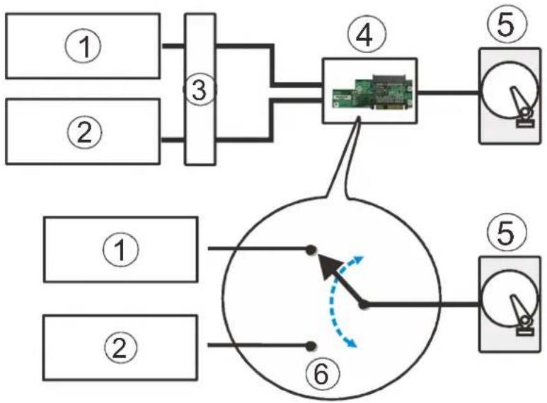
flowchart
graph TD
    A["①"] --> B["③"]
    C["②"] --> B
    B --> D["④"]
    D --> E["⑤"]
    D --> F["⑥"]
    G["①"] --> H["⑥"]
    I["②"] --> H
    H --> J["⑤"]
    style D fill:#f9f,stroke:#333
    style F fill:#ccf,stroke:#333
    style J fill:#cfc,stroke:#333
MUX Kit Port Selector Mechanism
SAS Interface
The SAS interface features a dual-ported connectivity with pins on both sides of its connector that include SAS primary links (1), power link (2) and underneath it, the SAS secondary links (3). The SATA drives have only one port that includes the SATA physical links (4) and the power link (5). The MUX-enabled drive trays must be separately purchased and applied.
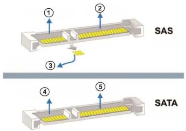
text_image
SAS ① ② ③ ④ ⑤ SATADual-ported SAS and Single-port SATA Connectors

WARNING
The hard drives and drive trays should only be installed into the system after rack mounting. If the hard drives are installed first, the system will be too heavy to handle and the possible impact during installation may damage your hard drives.
Handle hard drives with extreme care and observe all ESD prevention methods when installing drives.
Only use screws supplied with the system package. Longer screws may damage the drive.
Hard Drive Designation
Illustrations shown below are system hard drive slot number designations. Please familiarize yourself with the designations to avoid withdrawing the hard drive(s) out of the enclosure.
| 1 | 2 | 3 | 4 | 5 | 6 | 7 | 8 | 9 | 10 | 11 | 12 | 13 | 14 | 15 | 16 | 17 | 18 | 19 | 20 | 21 | 22 | 23 | 24 |
2U systems
| 1 | 2 | 3 | 4 |
| 5 | 6 | 7 | 8 |
| 9 | 10 | 11 | 12 |
| 13 | 14 | 15 | 16 |
3U systems
| 1 | 2 | 3 | 4 |
| 5 | 6 | 7 | 8 |
| 9 | 10 | 11 | 12 |
| 13 | 14 | 15 | 16 |
| 17 | 18 | 19 | 20 |
| 21 | 22 | 23 | 24 |
4U systems
Installing the Hard Drive into Drive Tray
Open the bezel by pressing the release button and gently pull out the tray.
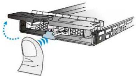
natural_image
Diagram of a computer interface showing a finger pressing a button with a dotted arrow indicating rotation (no text or symbols present)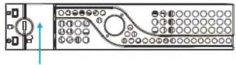
natural_image
Pure electrical circuit lines without any symbolsPlace the hard drive into the drive tray, making sure that the interface connector is facing the open side of the drive tray and its label side facing up.
If you want to install a SAS drive, an installed MUX board must be removed first.

natural_image
Technical line drawing of a vehicle chassis with front-mounted sensors and overhead crane (no text or symbols)Installing a 3.5" SAS HDD or single controller systems

natural_image
Technical line drawing of a vehicle chassis with front-mounted equipment and circular components (no text or symbols)Installing a 3.5" HDD with a MUX Board (SATA drives)
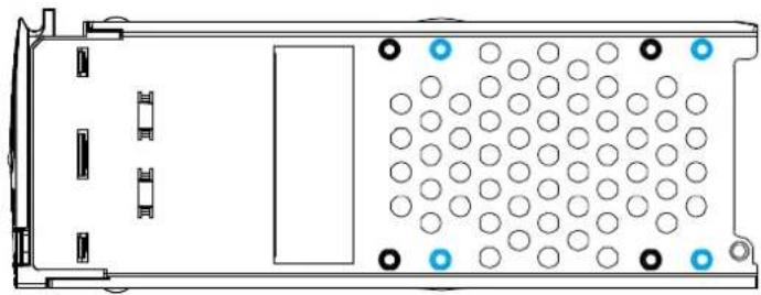
natural_image
Top-down schematic of a device casing with circular components and mounting holes (no text or symbols)2.5 inch SAS hard drive
- 2.5 inch SATA hard drive
Adjust the drive location until the mounting holes in the drive tray are aligned with those on the hard drive. Secure the drive with four of the supplied flat-head screws.
Installing the Hard Drive Tray into the Enclosure
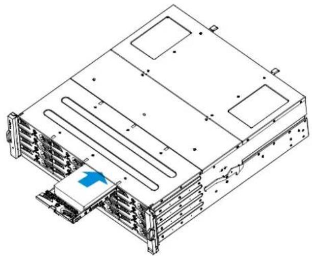
Once the hard drives have been installed in the drive trays, install the drive trays into the system.

WARNING
Each drive bay must be populated with a tray even if it does not contain a hard drive. An empty bay will disrupt ventilation and the system might overheat.
With the hard drive tray bezel opened, align and insert the tray into the enclosure.
natural_image
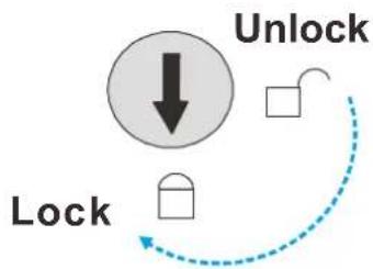
Technical line drawing of a server rack with ventilation ducts and a blue arrow indicating a component (no text or symbols present)Once fully inserted, close the tray and use a small-size flat blade screwdriver to turn the bezel lock from unlock to the lock position.
flowchart
graph TD
    A["Lock"] --> B["Unlock"]
    B --> C["Arrow to Lock"]
    style A fill:#f9f,stroke:#333
    style B fill:#ccf,stroke:#333
    style C stroke-dasharray: 5 5
Installing Host Boards

NOTE
Be aware that upgrading the controller / host board down time may occur.
If you add or replace a host board, the firmware will automatically restore the system to factory settings.
- Shutdown and remove the controller from the enclosure.
- For users installing a new host board, you will need to remove the screws holding the dummy covers in place.

natural_image
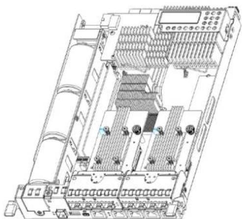
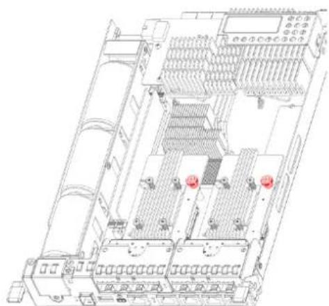
Diagram of a battery pack with two positive terminal indicators and internal battery cells (no text or labels)- If you are replacing an existing host board, please loosen the thumb screw that is securing the host board onto the controller and gently lift the host board.
natural_image
Technical line drawing of an electronic device chassis with multiple ports and connectors (no text or symbols visible)Guide pin (blue)
natural_image
Technical line drawing of an electronic device chassis with multiple ports and connectors (no text or symbols visible)Thumb screw on host board (red)
- By holding onto the edges of the PCB and using the "guide pin" for positioning, power the replacement host board into the controller. Tighten the thumb screw to complete the
installation. Reinsert the controller back into the system.
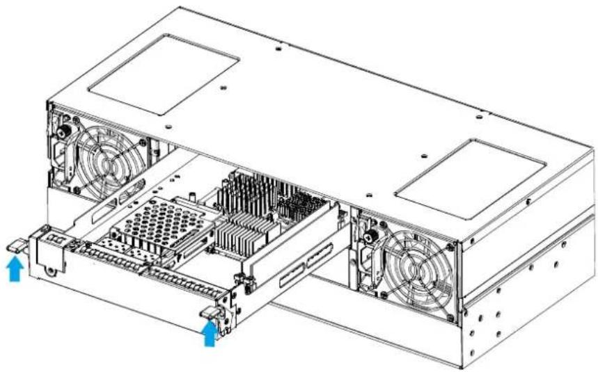
- Insert the controller slowly into the module slot. When you feel the contact resistance, use slightly more force and then push both of the ejection levers upwards (indicated by the blue arrows) to secure the controller into chassis.
natural_image
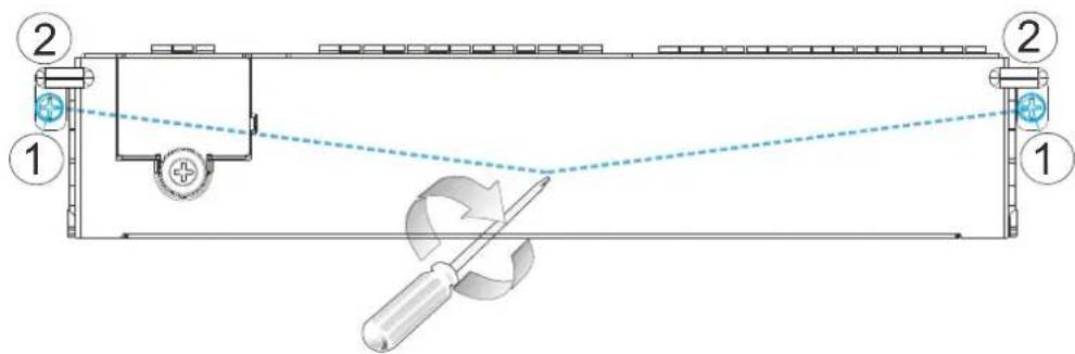
Technical line drawing of a computer tower drive showing internal components and fan structures (no text or labels)- Secure the controller by fastening the two retention screws (1) under the ejection levers (2).
text_image
Technical diagram showing a mechanical setup with labeled components and a tool, including a circular component and directional arrows.Removing the Controller
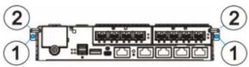
Loosen the screws (1) under the ejection levers (2).
text_image
Diagram of an Ethernet cable connector showing pin layout and terminal labelsPush ejection levers downwards and the controller will ease out from chassis.
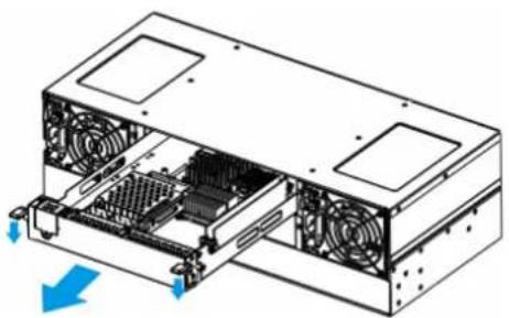
natural_image
Technical diagram of a computer drive showing internal components and fan structures (no text or labels)Installing the Controller
- Insert the controller slowly into the module slot. When you feel the contact resistance, use slightly more force and then push both of the ejection levers upwards (indicated by the blue arrows) to secure the controller into chassis.
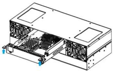
natural_image
Technical line drawing of a computer drive chassis showing internal components and fan array (no text or labels)- Secure the controller by fastening the two retention screws (1) under the ejection levers (2).
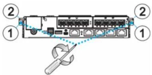
text_image
Diagram of an Ethernet cable connector showing ports, connectors, and a screwdriver tool interacting with itSystem Connection
This chapter outlines the general configuration rules you should follow when cabling a storage system and introduces basic information about topologies. You can use these topologies or refer to them as a guide for developing your own unique topologies. A complete description of the power-on and power-off procedures is also given in this chapter.
General Considerations on Making Connections
When selecting the number of hard drives to be included in a logical drive, the host channel bandwidth and the mechanical performance of individual disk drives should be considered.
It is a good practice to calculate performance against the host port bandwidth when designing an application topology. As an example, if eight members are included in a logical drive and this logical drive is associated with a host ID (LUN mapping), the combined performance of this logical drive should approximate the channel bandwidth. If, for example, two 6-drive logical arrays are associated with two IDs residing on a single host channel, there may be a trade-off with performance.
If your system comes with a total of 8+ host ports, it is recommended that you obtain more disk drives by attaching a JBOD so that you can create host-port corresponding 6-member logical drives (RAID-5) or 8-member logical drives (RAID-6). These logical drives leverage the bandwidth of each host port.
There are other considerations:
- For example, a spare drive carries no data stripes and will not contribute to disk-level performance. Refer to the documentation for your hard drives for performance data.
- The disk drives in the same logical array should have the same capacity, but it is preferred that all the drives within a chassis have the same capacity.
-
Disk drives in the same logical drive should have the same capacity, but it is preferred that all the disk drives within a chassis have the same capacity. Tiered storage configuration is supported. However, you should not include both SAS and SATA drives in a logical drive.
-
A spare drive should have a minimum capacity that is equivalent to the largest drive that it is expected to replace. If the capacity of the spare is less than the capacity of the drive it is expected to replace, the controller will not proceed with the failed drive rebuild.
- When cabling, follow all the specifications. Pay attention to signal quality and avoid electronic noise from adjacent interfaces, e.g., do not lay power cords on optical cables.
- When rack-mounted, leave enough slack in the cables so that they do not bend to a diameter of less than 76mm (3 inches).
- Route the cables away from places where it can be damaged by other devices, e.g., foot traffic or fan exhaust.
- Do not over-tighten or bend the cables.
Host-Side Topologies
The primary concern for configuring host-side topologies is to avoid points of failure. It is therefore recommended that the host ports are connected to at least two HBAs.

NOTE
In order to manage the fault-tolerant data paths and to optimize data throughput on multiple data paths, it is necessary to apply EonPath multipath software or utilities such as Linux Device Mapper.
Host port channel designation may vary from system to system, please refer to the following topologies as a guide to create your own connections to suit your needs.
Host-Side Parameters
It is STRONGLY recommended that users use the default settings with their system. Should you feel the need to adjust your host-side parameters, please consult on-site technical personnel or seek technical support from your vendor.
Maximum Concurrent Host LUN Connection ("Nexus" in SCSI)
The "Max Number of Concurrent Host-LUN Connection" menu option is used to set the maximum number of concurrent host-LUN connections.
Maximum concurrent host LUN connection (nexus in SCSI) is the arrangement of the controller internal resources for use with a number of the current host nexus.
For example, you can have four hosts (A, B, C, and D) and four host IDs/LUNs (IDs 0, 1, 2 and 3) in a configuration where:
- Host A accesses ID 0 (one nexus).
- Host B accesses ID 1 (one nexus).
- Host C accesses ID 2 (one nexus).
- Host D accesses ID 3 (one nexus).
These connections are all queued in the cache and are called four nexus.
If there is I/O in the cache with four different nexus, and another host I/O comes with a nexus different than the four in the cache (for example, host A accesses ID 3), the controller returns busy. This occurs with the concurrent active nexus; if the cache is cleared, it accepts four different nexus again. Many I/O operations can be accessed via the same nexus.
Maximum Queued I/O Count
The "Maximum Queued I/O Count" menu option enables you to configure the maximum number of I/O operations per host channel that can be accepted from servers. The predefined range is from 1 to 1024 I/O operations per host channel, or you can choose the "Auto" (automatically configured) setting. The default value is 256 I/O operations.
The appropriate "Maximum Queued I/O Count" setting depends on how many I/O operations the attached servers are performing. This can vary according to the amount of host memory present as well as the number of drives and their size. But usually, optimum performance results from using the "Auto" or "256" settings.
For more information, please refer to the Firmware Manual that came with your system.
Fibre-Host Connections

WARNING
All Fibre cables are sensitive and must be handled with care. To avoid interference, the cable routing path must be carefully planned and the cables must not be bent.
The Fibre Channel standard allows optical connections. Optical cables can be used over longer distances and have been shown to be more reliable. Due to the demands of high transfer rates, optical cables are preferred for 16/8/4Gbps fiber connectivity. Optical cables are not susceptible to EMI.
The Fibre host ports connect to Fibre Channel host adapters (HBA) that feature SFP interface that supports full-duplex transfer and come with a PCI-E interface. Please contact your vendor for the latest certified items.

WARNING
Lasers can be hazardous and may cause permanent eye damage or blindness, and therefore must be treated with respect and used with caution. Never look directly at lasers while it is turned on.
Auto speed detection
Speed auto-detection is specified by the Fibre Channel standard. If a 16Gbps port is connected to an 8Gbps port, it will negotiate down and run at 8Gbps. If there are 16Gbps ports on both ends of the link, the link will run at 16Gbps.
SFP / SFP+ transceivers
An SFP transceiver converts electrical data signals into light signals and transfers them transparently via optical fiber. A transceiver provides bi-directional data links, a laser transmitter (for fiber optic cables), LC connector, and a metal enclosure to lower the EMI.
Other beneficial features of a typical SFP transceiver include a single power supply, low power dissipation, and hot-swap capability. It is also important that any transceiver you use meets the FC performance and reliability specifications.

WARNING
The SFP transceiver contains a laser diode featuring class 1 laser. To ensure continued safety, do not remove any covers or attempt to gain access to the inside of the product. Refer all servicing to qualified personnel.
FC port dust plugs
Each FC port comes with a dust plug. Remove these dust plugs only when you are ready to insert an SFP transceiver.
Please contact your vendor for a list of compatible components!
Fibre-Host Topologies
The Fibre Channel standard supports three (3) separate topologies. They are point-to-point, Fibre Channel Arbitrated Loop (FC-AL), and fabric switch topologies.
- Point-to-Point: Point-to-point topology is the simplest topology. It is a direct connection between two (2) Fibre Channel devices.
- FC-AL: This is the most common topology currently in use. Fibre Channel devices are all connected to a loop. Each device is assigned an arbitrated loop physical address (AL_PA). The FC-AL supports 124 devices in a single loop.
- Fabric: The fabric topology supports up to 224 Fibre Channel devices. This topology allows multiple devices to communicate simultaneously. A Fibre switch is required to implement this topology.

NOTE
If a logical drive has to be accessed by different servers, file locking, FC switch zoning, port binding, and multipath access control will be necessary.
Fibre Cabling
Following are steps that should be completed with cabling:
- Maintain a configuration plan. In addition to cabling topologies and list of networking components, the plan can also include firmware and software maintenance details.
- Confirm that you have a Fibre Channel cable that loops 6-inch or longer.
- Ensure proper airflow and keep cables away from ventilation airflow outlets.
Cabling steps:
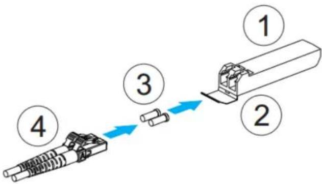
- Remove the SFP module (1) from its static-protective package.
- Remove the dust plug (2) from the SFP transceiver module.
flowchart
graph LR
    A["Step 1: Connector"] --> B["Step 2: Component"]
    B --> C["Step 3: Component"]
    C --> D["Step 4: Component"]
    D --> E["Step 5: Component"]
- Insert the SFP module into one of the system host ports. The module will snap into place.
- Remove the two protective caps (3) from the LC-to-LC type cable. Save the protective caps for future use
- Connect a LC-to-LC type cable (4).
- Carefully insert the cable into an SFP module that is already on the system. The cable connector is keyed and will click into place.
- Remove the protective caps on the other end and connect this end to an SFP transceiver module on a Fibre Channel switch port or a Fibre Channel host bus adapter (HBA) port.
Simple End-to-End Connection
flowchart
graph TD
    subgraph RAID
        ALV1["ALV BLV"] --> ALV2["ALV BLV"]
        ALV2 --> LD1["LD"]
        ALV2 --> LD2["LD"]
        ALV2 --> LD3["LD"]
        ALV1 --> LD4["LD"]
        ALV2 --> LD5["LD"]
        ALV1 --> LD6["LD"]
        ALV2 --> LD7["LD"]
        ALV1 --> LD8["LD"]
        ALV2 --> LD9["LD"]
        ALV1 --> LD10["LD"]
        ALV2 --> LD11["LD"]
        ALV1 --> LD12["LD"]
        ALV2 --> LD13["LD"]
        ALV1 --> LD14["LD"]
        ALV2 --> LD15["LD"]
        ALV1 --> LD16["LD"]
        ALV2 --> LD17["LD"]
        ALV1 --> LD18["LD"]
        ALV2 --> LD19["LD"]
        ALV1 --> LD20["LD"]
        ALV2 --> LD21["LD"]
        ALV1 --> LD22["LD"]
        ALV2 --> LD23["LD"]
        ALV1 --> LD24["LD"]
        ALV2 --> LD25["LD"]
        ALV1 --> LD26["LD"]
        ALV2 --> LD27["LD"]
        ALV1 --> LD28["LD"]
        ALV2 --> LD29["LD"]
        ALV1 --> LD30["LD"]
        ALV2 --> LD31["LD"]
        ALV1 --> LD32["LD"]
        ALV2 --> LD33["LD"]
        ALV1 --> LD34["LD"]
        ALV2 --> LD35["LD"]
        ALV1 --> LD36["LD"]
        ALV2 --> LD37["LD"]
        ALV1 --> LD38["LD"]
        ALV2 --> LD39["LD"]
        ALV1 --> LD40["LD"]
    end

    subgraph JBOD
        CH0A0["HBA 0"] --> EonPath["EonPath"]
        CH0B0["HBA 1"] --> EonPath
        CH0A1["HBA 0"] --> EonPath
        CH0B1["HBA 0"] --> EonPath
        CH0A2["HBA 0"] --> EonPath
        CH0B2["HBA 0"] --> EonPath
        CH0A3["HBA 0"] --> EonPath
        CH0B3["HBA 0"] --> EonPath
        CH0A4["HBA 0"] --> EonPath
        CH0B4["HBA 0"] --> EonPath
        CH0A5["HBA 0"] --> EonPath
        CH0B5["HBA 0"] --> EonPath
        CH0A6["HBA 0"] --> EonPath
        CH0B6["HBA 0"] --> EonPath
        CH0A7["HBA 0"] --> EonPath
        CH0B7["HBA 0"] --> EonPath
        CH0A8["HBA 0"] --> EonPath
        CH0B8["HBA 0"] --> EonPath
        CH0A9["HBA 0"] --> EonPath
        CH0B9["HBA 0"] --> EonPath
        CH0A10["HBA 0"] --> EonPath
        CH0B10["HBA 0"] --> EonPath
        CH0A11["HBA 0"] --> EonPath
        CH0B11["HBA 0"] --> EonPath
        CH0A12["HBA 0"] --> EonPath
        CH0B12["HBA 0"] --> EonPath
        CH0A13["HBA 0"] --> EonPath
        CH0B13["HBA 0"] --> EonPath
        CH0A14["HBA 0"] --> EonPath
        CH0B14["HBA 0"] --> EonPath
        CH0A15["HBA 0"] --> EonPath
        CH0B15["HBA 0"] --> EonPath
        CH0A16["HBA 0"] --> EonPath
        CH0B16["HBA 0"] --> EonPath
        CH0A17["HBA 0"] --> EonPath
        CH0B17["HBA 0"] --> EonPath
        CH0A18["HBA 0"] --> EonPath
        CH0B18["HBA 0"] --> EonPath
        CH0A19["HBA 0"] --> EonPath
        CH0B19["HBA 0"] --> EonPath
        CH0A20["HBA 0"] --> EonPath
        CH0B20["HBA 0"] --> EonPath
        CH0A21["HBA 0"] --> EonPath
        CH0B21["HBA 0"] --> EonPath
        CH0A22["HBA 0"] --> EonPath
        CH0B22["HBA 0"] --> EonPath
        CH0A23["HBA 0"] --> EonPath
        CH0B23["HBA 0"] --> EonPath
        CH0A24["HBA 0"] --> EonPath
    end
| Channels | Controller A | Controller B | |
| Host | CH0, CH1, CH2, CH3 | CH0, CH1, CH2, CH3 | |
| Configuration Information | |||
| Controller | 2 | ||
| Host server | 2 | ||
| Data path connection | Fault-tolerant data paths. | ||
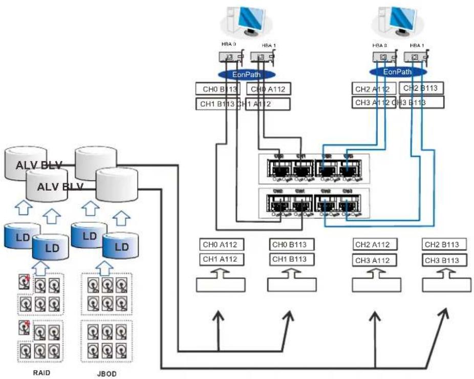
Above is an example demonstrating simple end-to-end connections with each SFP port connected to a host adapter. Multiple logical drives, logical volumes, and logical partitions can be created and each mapped to the corresponding host channel ID/LUN combinations.
Note that EonPath multipath software or Linux Device Mapper is necessary for controlling and optimizing the access to logical drives via multiple data paths.
DAS (Direct-Attached) Connection

NOTE
If a logical drive has to be accessed by different servers, file locking, FC switch zoning, port binding, and multipath access control will be necessary in order to avoid access contention.
flowchart
graph TD
    subgraph EonPath
        A["CH0 ID112"] --> B["LD0"]
        C["CH1 ID112"] --> D["LD0"]
    end
    subgraph LD1
        E["CH0 ID112"] --> F["LD0"]
        G["CH1 ID112"] --> H["LD0"]
        I["CH3 ID112"] --> J["LD0"]
    end
    H --> K["LED1"]
    style EonPath fill:#4CAF50,stroke:#333
    style LD1 fill:#4CAF50,stroke:#333
| Channels | Controller A | |
| Host | CH0, CH1, CH2, CH3 | |
| Configuration Information | ||
| Controller | 1 | |
| Host server | 2 | |
| Data path connection | Simple end-to-end connections with fault-tolerant pairs | |
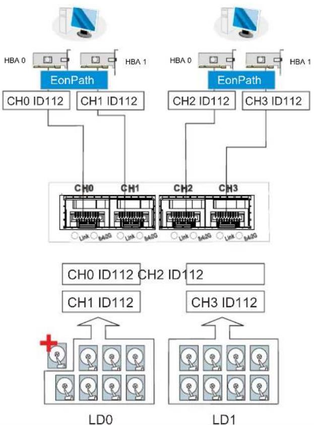
With more disk drives over SAS expansion links, you can create more logical groups of drives. These logical drives using more host channel IDs or LUN numbers.
If a server has multiple data paths to a Storage System system, a multi-path software is necessary, e.g., the EonPath driver.
The two logical drives in the above drawing cannot leverage the full computer power of the system. You may attach 1 or 2 more JBODs to acquire more end-to-end performance.
Switched Fabric Connection (Dual-Controller)

NOTE
A logical partition presented through LUN Mapping can be seen by all servers across SAN. Make sure you have access control such as file-locking, switch zoning, port binding, etc., to avoid access contention.
flowchart
graph TD
    subgraph_Left_EonPath["OnPath"]
        A1["CH0 A112"] --> B1["ALV BLV"]
        A2["CH2 A116"] --> B1
        A3["CH0 B113"] --> B1
        A4["CH2 B117"] --> B1
    end

    subgraph_Right_EonPath["OnPath"]
        B1 --> C1["ALV BLV"]
        B2["CH0 B114"] --> C1
        B3["CH2 B118"] --> C1
        B4["CH0 A115"] --> C1
        B5["CH2 A119"] --> C1
    end

    subgraph_Right_EonPath["OnPath"]
        C1 --> D1["ALV BLV"]
        C2["CH0 B113"] --> D1
        C3["CH2 B118"] --> D1
        C4["CH0 A115"] --> D1
        C5["CH2 A119"] --> D1
    end

    Left_ALV["ALV BLV"] --> AL["ALV BLV"]
    Left_ALV --> ALDL["LD"]
    Left_ALV --> ALLD["LD"]
    Left_ALV --> RAID["RAID"]
    Left_ALV --> JBOD["JBOD"]

    subgraph Right_EonPath
        C3 --> D2["ALV BLV"]
        C4 --> D2
        C5 --> D2
        C6 --> D2
        C7 --> D2
        C8 --> D2
        C9 --> D2
    end

    Left_ALV --> ALDL
    Left_ALV --> RAID
    Left_ALV --> JBOD
    Left_ALV --> RAID
    Left_ALV --> JBOD
    Left_ALV --> RAID
    Left_ALV --> RAID
    Left_ALV --> RAID
    Left_ALV --> RAID
    Left_ALV --> RAID
    Left_ALV --> RAID
    Left_ALV --> RAID
    Left_ALV --> RAID
    Left_ALV --> RAID
    Left_ALV --> RAID
    Left_ALV --> RAID
    Left_ALV --> RAID
    Left_ALV --> RAID
    Left_ALV --> RAID
    Left_ALV --> RAID

    subgraph Right_EonPath
        C5 --> D3["ALV BLV"]
        C6 --> D3
        C7 --> D3
        C8 --> D3
        C9 --> D3
        C10 --> D3
        C11 --> D3
        C12 --> D3
        C13 --> D3
        C14 --> D3
        C15 --> D3
        C16 --> D3
        C17 --> D3
        C18 --> D3
        C19 --> D3
        C20 --> D3
        C21 --> D3
        C22 --> D3
        C23 --> D3
        C24 --> D3
        C25 --> D3
        C26 --> D3
        C27 --> D3
        C28 --> D3
        C29 --> D3
        C30 --> D3
        C31 --> D3
        C32 --> D3
        C33 --> D3
        C34 --> D3
        C35 --> D3
        C36 --> D3
        C37 --> D3
        C38 --> D3
        C39 --> D3
        C40 --> D3
        C41 --> D3
        C42 --> D3
        C43 --> D3
        C44 --> D3
        C45 --> D3
        C46 --> D3
        C47 --> D3
        C48 --> D3
        C49 --> D3
        C50 --> D3
    end
| Channels | Controller A | Controller B | |
| Host | CH0, CH1, CH2, CH3 | CH0, CH1, CH2, CH3 | |
| Configuration Information | |||
| Controller | 2 | ||
| Host server | 4 (or more via FC switches) | ||
| FC switch | 2 (or 1 into 2 zones) | ||
| Data path connection | Fault-tolerant paths | ||
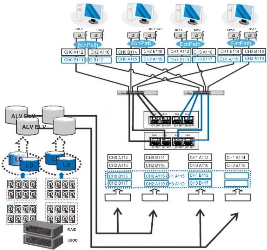
Channel link bypass is provided on external FC switches. Each of the application servers shown in the diagram is equipped with two HBAs with FC links via two FC switches to the SFP ports on individual controllers.
You can refer to the ID tags on the host links to see the related logical volume mapping and cable links routing paths. Through the cable links illustrated above, the configuration can withstand a failure of a single component, e.g., controller, HBA, cable, or FC switch.
Each logical partition is redundantly mapped to multiple host channel IDs in an AAPP (Active-Active-Passive-Passive) configuration. Logical volumes are managed either by the controller A or by the controller B. The Passive IDs will only become functional when a Single-Controller fails in the system. The EonPath driver is a must on the application servers. The driver communicates with system firmware and performs load balance and automated distribution of I/O's across preferred paths (Active IDs on data paths). TPGS (Target Port Group Service) is supported so that I/O's are routed to the preferred paths.
Switched Fabric Connection (Single-Controller)
flowchart
graph TD
    subgraph_HBA_0["HBA 0"]
        A1["Ch0 A112"] --> B1["EonPath"]
        A2["Ch0 A115"] --> B1
        B1 --> C1["CH0 CH1 CH2 CH3"]
    end

    subgraph_HBA_1["HBA 1"]
        A3["Ch0 B114"] --> B2["EonPath"]
        A4["Ch0 B113"] --> B2
        B2 --> C2["CH0 CH1 CH2 CH3"]
    end

    D["Network Top: CH0 A112, CH1 A112, CH0 B113, CH1 B113, CH0 A115"] --> E["Image Group 1"]
    F["Network Bottom: CH0 A115, CH0 B115"] --> G["Image Group 2"]
LD0 LD1
| Channels | Controller A | |
| Host | CH0, CH1, CH2, CH3 | |
| Configuration Information | ||
| Controller | 1 | |
| Host server | 4 | |
| Data path connection | Data paths are attached to one or more FC switches. SAN management measures, such as switch zoning and port binding, should be taken to avoid multiple servers from accessing the same LUN. | |
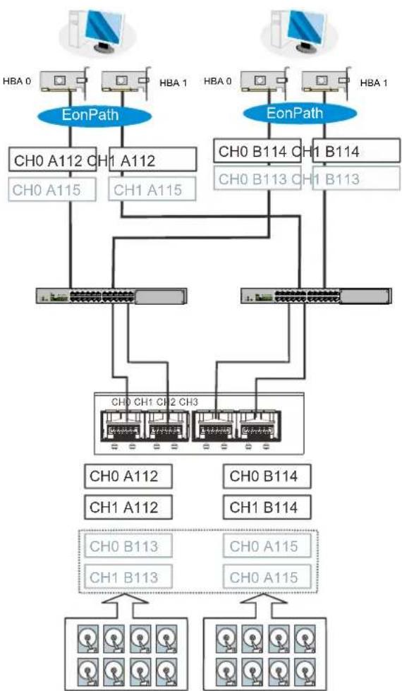
Above is the sample drawing showing connections with each SFP port connected to FC switches and then to host adapters. See logical associations in the drawing for LUN mapping details.
Use Enclosure-specific spares to prevent a spare drive from participating in the rebuild of a logical drive on another enclosure.
You can refer to the ID tags on the host links to see the related LUN mapping and cable links routing paths.
Each logical partition is mapped to a single host channel ID. If you prefer path redundancy, you can map a logical partition to IDs residing on two different channels. You will then need the EonPath driver to manage access through two different HBA ports. The driver communicates with system firmware and performs load balance and automated distribution of I/O.
If multiple servers can “see” a mapped volume, you will need to avoid access contention using file locking software, port binding, or zoning feature by FC switches, which limits the access from host to a specific LUN. If you have two servers in a clustered configuration, access control will be performed by the clustering software.
SAS-Host Connections
Please contact your vendor to purchase compatible host-link cables.
SAS cables (28AWG x 8 pairs) are characterized by 100ohm, black colors, UL-approved, lead-free, 50, 120 or 170cm cable lengths; connectors can be secured to chassis receptacle using latching mechanism.

WARNING
All SAS cables are sensitive and must be handled with care. To prevent interference within a rack system, the cable routing path must be carefully planned and the cables must not be bent.
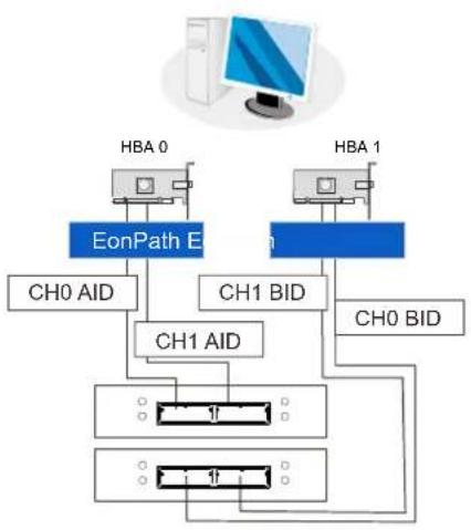
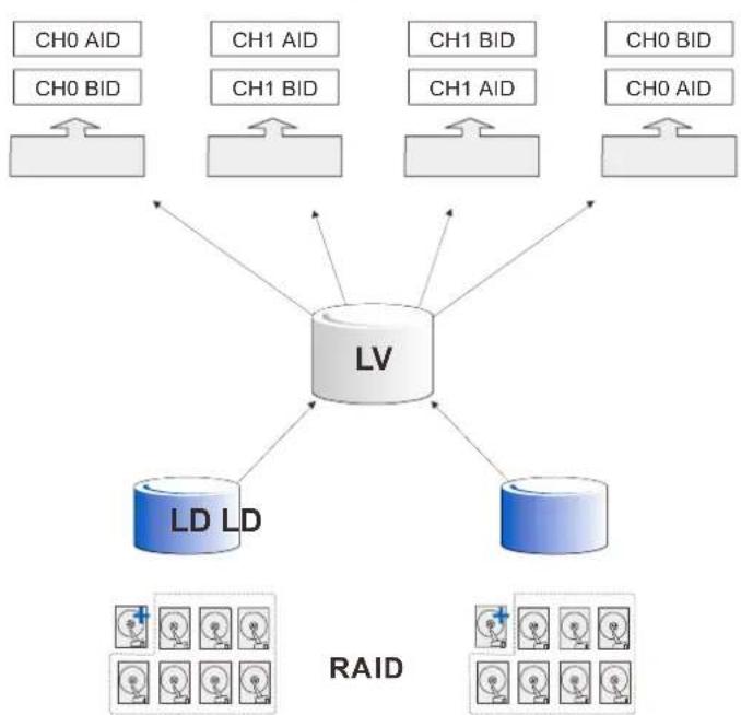
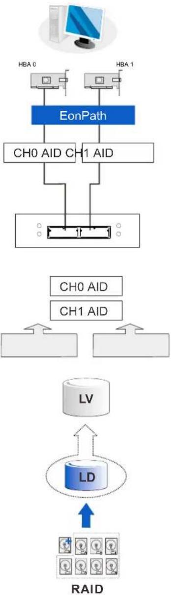
DAS (Direct-Attached Storage) Connection with Redundant Host Path
Dual-Controller models
flowchart
graph TD
    A["HBA 0"] --> B["EonPath E"]
    C["HBA 1"] --> D["CH1 BID"]
    B --> E["CH0 AID"]
    D --> F["CH0 BID"]
    B --> G["CH1 AID"]
    D --> H["CH1 BID"]
    G --> I["Output"]
    H --> J["Output"]
flowchart
graph TD
    A["LV"] --> B["LD LD"]
    A --> C["RAID"]
    A --> D["CH0 BID"]
    A --> E["CH1 BID"]
    A --> F["CH0 BID"]
    A --> G["CH1 BID"]
    A --> H["CH0 BID"]
    style A fill:#f9f,stroke:#333
    style B fill:#bbf,stroke:#333
    style C fill:#bbf,stroke:#333
    style D fill:#dfd,stroke:#333
    style E fill:#dfd,stroke:#333
    style F fill:#dfd,stroke:#333
    style G fill:#dfd,stroke:#333
    style H fill:#dfd,stroke:#333
Single-Controller models
flowchart
graph TD
    A["HBA 0"] --> B["EonPath"]
    C["HBA 1"] --> B
    B --> D["CH0 AID CH1 AID"]
    D --> E["RD"]
    F["CH0 AID"] --> G["LV"]
    H["CH1 AID"] --> G
    G --> I["LD"]
    I --> J["RAID"]
    J --> K["Image icons"]
With more hard drives over SAS expansion links, you can create more logical groups of drives. Avail these logical partitions using more LUN numbers.

NOTE
EonPath multipath software or Linux Device Mapper is necessary for controlling and optimizing the access to logical drives via multiple data paths (Windows 2003 server only).
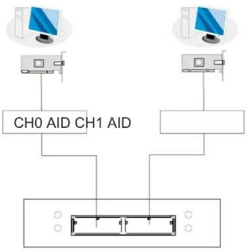
DAS (Direct-Attached Storage) Connection to Two Servers
flowchart
graph TD
    A["Computer 1"] --> C["CH0 AID CH1 AID"]
    B["Computer 2"] --> C
    C --> D["Device with four ports"]
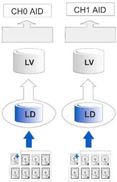
flowchart
graph TD
    subgraph_CH0_AID["CH0 AID"]
        A["LV"] --> B["LD"]
    end
    subgraph_CH1_AID["CH1 AID"]
        C["LV"] --> D["LD"]
    end
    B --> E["Medical imaging icons"]
    D --> F["Medical imaging icons"]
    style CH0_AID fill:#f9f,stroke:#333
    style CH1_AID fill:#f9f,stroke:#333
RAID

NOTE
If you would like a LUN (a logical partition) to be accessed by multiple hosts, file locking or multipath access control will be necessary.
Ethernet-Host Connections
Ethernet cable requirements:
- Ethernet cables are user-supplied. Cat5e shielded STP type network cables or better performance types (important for meeting the requirements imposed by emission standards).
- Straight-through Ethernet cables with RJ-45 plugs.
- Use of cross-over cables can also be automatically detected and re-routed for a valid connection.
Connection types:
- Directly to iSCSI initiators (software or hardware) or via Gigabit Ethernet switches.
- To servers equipped with iSCSI HBA – preferably a hardware TOE (TCP/IP Offload Engine) card, and then to client stations with an Ethernet NIC or iSCSI HBA.
- The system presents its logical volumes through SCSI-like IDs and LUNs. These RAID volumes then appear as iSCSI targets through the network.

NOTE
Even though iSCSI initiator software is a cost-effective way of building an iSCSI SAN, software initiator adds additional workload to the server CPU. It is recommended to apply iSCSI HBAs that come with TCP/IP offload engines in order to reduce overhead.
Network & Host Connection Topologies
The iSCSI host ports connect to Ethernet network devices and iSCSI initiators that comply with the IETF iSCSI standard (RFC 3720). Network connection of the iSCSI ports is flexible. The use of network connecting devices, subnet, Name Servers, or iSCSI management software can vary from case to case. In the following sections, configuration diagrams will be provided to illustrate the possible uses of the EonStor DS system in an iSCSI network.
Note that host NIC ports and the storage system's iSCSI host ports must be configured into the same subnet.
Please note the following:
- Use the Ethernet management port for management purposes only, i.e., SANWatch or telnet console. This Ethernet management port is not used for I/O transactions.
- Configurations such as subnet or Virtual LAN can separate iSCSI host links, decrease overhead, and eliminate the impact of link failure.
- Multiple arrays or logical partitions can be created and made available separately through different IDs or LUN numbers on the host ports. Usually, a RAID5 logical drive of eight (8) members often brings optimal array performance.

NOTE
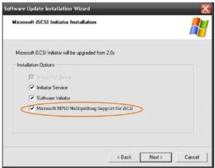
If you are using Microsoft's software initiator, please de-select the embedded MPIO function when installing the software, as the MPIO selection creates conflicts with EonPath driver.
text_image
Software Update Installation Wizard Microsoft iSCSI Initiator Installation Microsoft iSCSI Initiator will be upgraded from 2.0x Installation Options ✓ Visual Port Driver ✓ Initiator Service ✓ Software Initiator ✓ Microsoft MPIO Multipathing Support for iSCSI < Back Next > CancelHigh Availability IP SAN with Redundant Controller
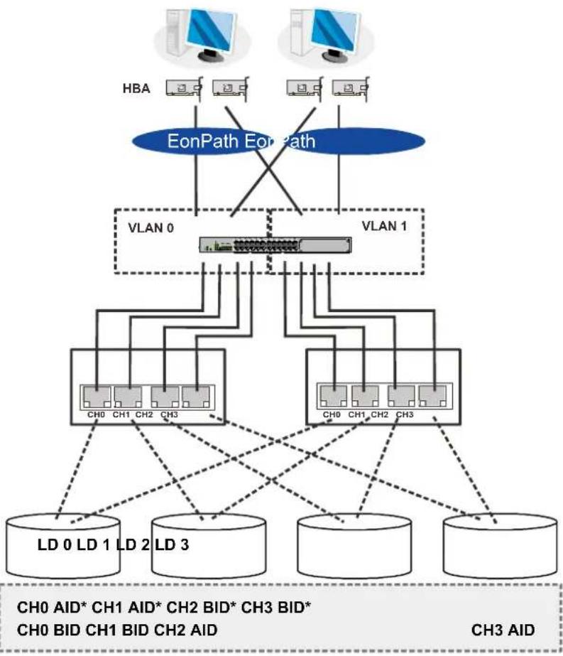
flowchart
graph TD
    subgraph HBA
        HBA1["Computer"] -->|HBA| HBA2["Computer"]
        HBA3["Computer"] -->|HBA| HBA4["Computer"]
        HBA5["Computer"] -->|HBA| HBA6["Computer"]
    end

    subgraph EonPath EonPath
        EonPathEonPath --> VLAN0["VLAN 0"]
        EonPathEonPath --> VLAN1["VLAN 1"]
    end

    VLAN0 --> CH0["CH0"]
    VLAN0 --> CH1["CH1"]
    VLAN0 --> CH2["CH2"]
    VLAN0 --> CH3["CH3"]
    VLAN1 --> CH0
    VLAN1 --> CH1
    VLAN1 --> CH2
    VLAN1 --> CH3
    CH0 --> LD0["LD 0"]
    CH0 --> LD1["LD 1"]
    CH0 --> LD2["LD 2"]
    CH0 --> LD3["LD 3"]
    CH1 --> LD0
    CH1 --> LD1
    CH1 --> LD2
    CH1 --> LD3
    CH2 --> LD0
    CH2 --> LD1
    CH2 --> LD2
    CH2 --> LD3
    CH3 --> LD0
    CH3 --> LD1
    CH3 --> LD2
    CH3 --> LD3
    Dotted lines indicate connections from each device to the network layers.
| Component | Description |
| Storage System system | Redundant controllers, with a total of 8 host ports |
| HBA | iSCSI initiators, preferably PCI-E TCP/IP offload engine (TOE) capable cards |
| GbE cables | GbE network cables |
| GbE switch | Ports divided into 2 virtual LANs to separate access from host to targets. |
| Software | EonPath to manage the fault-tolerant paths with failover/failback and load balance capabilities. Use EonPath multipath software so that your operating system can identify alternate paths to the same logical drive. |
| RAID configuration | Remote replication functionality is not supported using this configuration. For remote replication setup, please refer to “High Availability IP SAN (Remote Replication Enabled) or “High Availability IP SAN with Port Trunk (Remote Replication Enabled)".4 logical drives (each has 4 member drives; for better performance, you can include drives from JBOD)LD0 mapped to CH0 AID and CH0 BID; LD assigned to controller ALD1 mapped to CH1 AID and CH1 BID; LD assigned to controller ALD2 mapped to CH2 AID and CH2 BID; LD assigned to controller BLD3 mapped to CH3 AID and CH3 BID; LD assigned to controller B |
| * | LD assignment |

NOTE
In the event of Single-Controller failure, a logical drive is accessed through the host IDs managed by the alternate controller. Host IDs and port IPs do fail-over to the surviving controller. Therefore, the EonPath multipath driver is necessary for path redundancy and controller failover.
not
Single-Controller with Fault-Tolerant Path
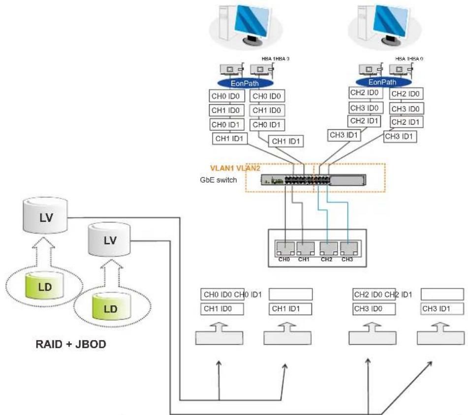
flowchart
graph TD
    A["RAID + JBOD"] --> B["LV"]
    A --> C["LV"]
    B --> D["LD"]
    C --> E["LD"]
    D --> F["LV"]
    E --> F
    F --> G["LV"]
    G --> H["EonPath"]
    H --> I["HBA 1HBA 3"]
    H --> J["HBA 1HBA 0"]
    I --> K["EonPath"]
    J --> K
    K --> L["VLAN1 VLAN2\nGbE switch"]
    L --> M["Ch0 ID0 CH1 ID0 CH0 ID1 CH1 ID1 CH1 ID1 CH3 ID1 CH3 ID1"]
    L --> N["Ch0 ID0 CH1 ID0 CH0 ID1 CH1 ID1 CH3 ID0 CH3 ID1"]
    N --> O["Ch0 ID0 CH1 ID0 CH0 ID1 CH1 ID1 CH3 ID0 CH3 ID1"]
    O --> P["Ch0 ID0 CH1 ID0 CH0 ID1 CH1 ID1 CH3 ID0 CH3 ID1"]
    P --> Q["Ch0 ID0 CH1 ID0 CH0 ID1 CH1 ID1 CH3 ID0 CH3 ID1"]
    Q --> R["Ch0 ID0 CH1 ID0 CH0 ID1 CH1 ID1 CH3 ID0 CH3 ID1"]
    R --> S["Ch0 ID0 CH1 ID0 CH0 ID1 CH1 ID1 CH3 ID0 CH3 ID1"]
    S --> T["Ch0 ID0 CH1 ID0 CH0 ID1 CH1 ID1 CH3 ID0 CH3 ID1"]
    T --> U["Ch0 ID0 CH1 ID0 CH0 ID1 CH1 ID1 CH3 ID0 CH3 ID1"]
| Component | Description |
| Storage System system | Single-Controller, with a total of 4 host ports |
| HBA or NIC | iSCSI initiators, preferably PCI-E TCP/IP offload engine (TOE) capable cards |
| GbE cables | GbE network cables |
| Software | EonPath to manage the fault-tolerant paths with failover/failback and load balance |
| RAID configuration | 4 logical partitions (created from 2 logical volumes)2 Logical Volumes (each contains a logical drive)2 Logical Drives* Each logical partition appears on two different host links for the purpose of fault tolerance. Use EonPath multipath software so that your operating system can identify alternate paths to the same logical drive. |
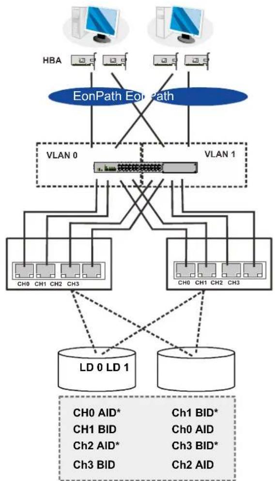
High Availability IP SAN (Recommended for Remote Replication)
flowchart
graph TD
    subgraph HBA
        A["Computer"] --> B["EonPath EonPath"]
        C["Computer"] --> B
        D["Computer"] --> B
        B --> E["VLAN 0"]
        B --> F["VLAN 1"]
        E --> G["Ch0 CH1 CH2 CH3"]
        F --> H["Ch0 CH1 CH2 CH3"]
    end

    I["LD 0 LD 1"] --> J["Ch0 AID*"]
    I --> K["Ch1 BID*"]
    I --> L["Ch0 AID"]
    I --> M["Ch2 AID*"]
    I --> N["Ch3 BID*"]
    I --> O["Ch2 AID"]
    P["Ch0 AID*"] --> Q["LD 0 LD 1"]
    R["Ch1 BID*"] --> Q
    S["Ch0 AID"] --> Q
    T["Ch2 AID*"] --> Q
    U["Ch3 BID*"] --> Q
    V["Ch2 AID"] --> Q
| Component | Description |
| Storage System system | Redundant controllers, with a total of 8 host ports. |
| HBA | iSCSI initiators, preferably PCI-E TCP/IP offload engine (TOE) capable cards. |
| GbE cables | GbE network cables |
| GbE switch | Ports divided into 2 virtual LANs; both controllers are linked to both virtual LAN zones. |
| Software | EonPath to manage the fault-tolerant paths with failover/failback and load balance. Use EonPath multipath software so that your operating system can identify alternate paths to the same logical drive. |
| RAID configuration | 2 logical drives (each has 8 member drives). More logical drives can be created from drives in JBOD.LD0 mapped to CH0 AID, CH1 BID, CH2 AID and CH3 BID; LD has to be assigned to both controllers A and B to enable remote replication.LD1 mapped to CH1 BID, CH0 AID CH3 BID and CH2 AID; LD has to be assigned to both controllers A and B to enable remote replication. |

NOTE
In the event of Single-Controller failure, a logical drive is accessed through the host IDs managed by the alternate controller. Host IDs and port IPs do not fail-over to the surviving controller. Therefore, the EonPath multipath driver is necessary for path redundancy and controller failover (Windows 2003 server only).
High Availability IP SAN with Port Trunk (Remote Replication Enabled)
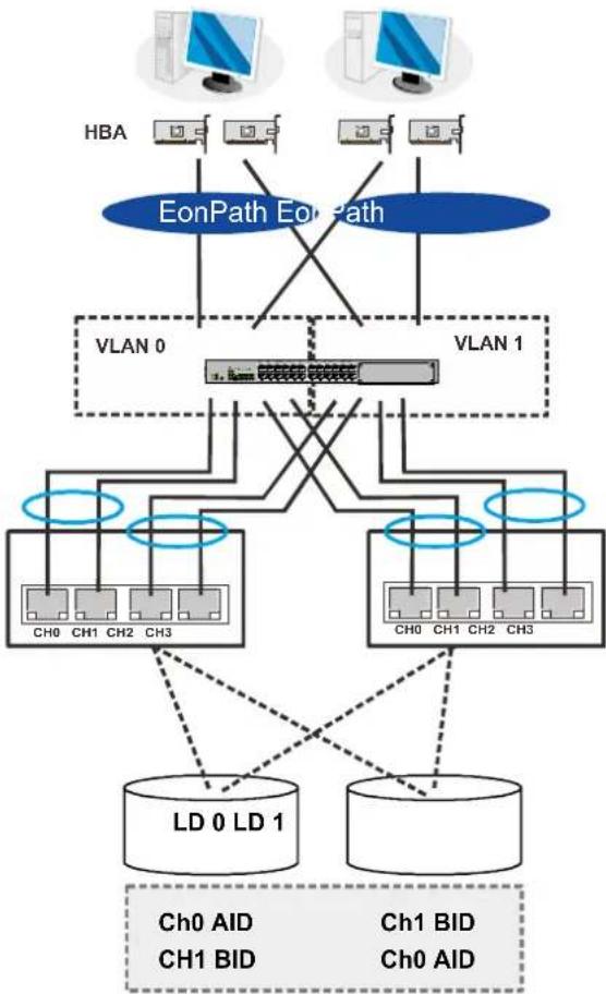
flowchart
graph TD
    subgraph EonPath_EonPath
        HBA["HBA"] --> VLAN0["VLAN 0"]
        HBA --> VLAN1["VLAN 1"]
    end
    subgraph VLAN 0
        CH0["CH0"] --> VLAN1
        CH1["CH1"] --> VLAN1
        CH2["CH2"] --> VLAN1
        CH3["CH3"] --> VLAN1
    end
    subgraph VLAN 1
        CH0A["CH0 AID"] --> VLAN1A["LD 0 LD 1"]
        CH1B["CH1 BID"] --> VLAN1B["LD 0 LD 1"]
        Ch0A["D"] --> VLAN1A
        Ch1B["D"] --> VLAN1B
    end
    HBA -.-> VLAN0
    HBA -.-> VLAN1
    VLAN0 -.-> VLAN1
    VLAN1 -.-> VLAN0
    VLAN1 -.-> VLAN1A
    VLAN1 -.-> VLAN1B
    style EonPath_EonPath fill:#4CAF50,stroke:#388E3C
    style VLAN0 fill:#4CAF50,stroke:#388E3C
    style VLAN1 fill:#4CAF50,stroke:#388E3C
    style VLAN0 fill:#FFD700,stroke:#388E3C
    style VLAN1 fill:#FFD700,stroke:#388E3C
    style VLAN0 fill:#90EE90,stroke:#388E3C
    style VLAN1 fill:#90EE90,stroke:#388E3C
| Component | Description |
| Storage System system | Redundant controllers, with a total of 8 host ports |
| HBA | iSCSI initiators, preferably PCI-E TOE cards |
| GbE cables | GbE network cables; port-trunking indicated by the blue circles |
| GbE switch | Ports divided into 2 virtual LANs; both controllers are linked to both virtual LAN zones |
| Software | EonPath to manage the fault-tolerant paths with failover/failback and load balance. Use EonPath multipath software so that your operating system can identify alternate paths to the same logical drive. |
| RAID configuration | 2 logical drives (each has 8 member drives). More logical drives can be created from drives in JBOD.LD0 mapped to CH0 AID and CH1 BID; LD has to be assigned to both controllers A and B to enable remote replicationLD1 mapped to CH1 BID and CH0 AID; LD has to be assigned to both controllers A and B to enable remote replication |
Hybrid Host Connections
For hybrid systems that feature two additional iSCSI ports, they can be used for remote replication or be used for host LUN mapping if users wish to do so.
Single Hybrid Unit Connected to FC/iSCSI Hosts
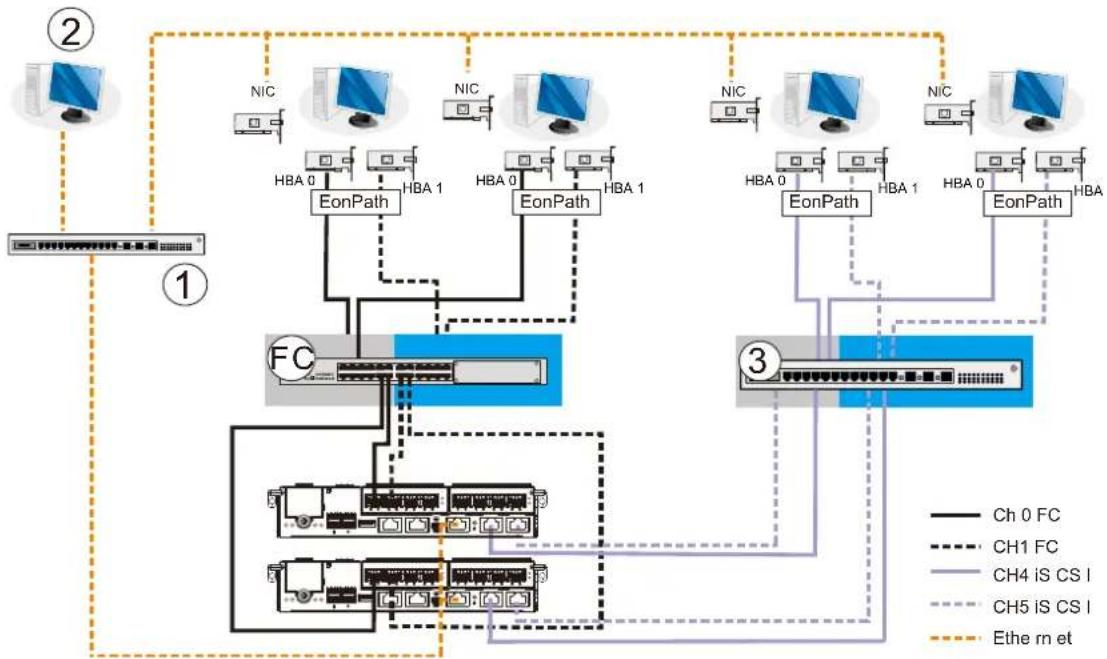
flowchart
graph TD
    subgraph Section 1
        A["②"] --> B["①"]
        C["NIC"] --> D["EonPath"]
        D --> E["HBA 0"]
        D --> F["HBA 1"]
        G["NIC"] --> H["EonPath"]
        H --> I["HBA 0"]
        H --> J["HBA 1"]
        K["NIC"] --> L["EonPath"]
        L --> M["HBA 0"]
        L --> N["HBA 1"]
        O["NIC"] --> P["EonPath"]
        P --> Q["HBA 0"]
        P --> R["HBA 1"]
        S["NIC"] --> T["EonPath"]
        T --> U["HBA 0"]
        T --> V["HBA 1"]
        W["NIC"] --> X["EonPath"]
    end
    subgraph Section 2
        Y["③"] --> Z["①"]
        AA["FC"] --> AB["EC Network"]
        AB --> AC["Ch0 FC"]
        AB --> AD["CH1 FC"]
        AB --> AE["CH4 IS CS I"]
        AB --> AF["CH5 IS CS I"]
        AG["③"] --> AH["①"]
        AI["③"] --> AJ["①"]
        AK["Ethe m et"]
    end
When connected to both FC host and iSCSI host, the connections will work in their respective speeds. It maximizes the number of connections while keeping the optimum performance gained by the high speed FC link and FC switch (FC).

NOTE
To gain optimum performance, make sure the LAN switch (1) for the management station (2), the LAN switch for the systems, and the iSCSI switch (3) for iSCSI host link are separated.
Otherwise, the host might consider the iSCSI connection as part of host connection and might use it for data I/O, even if the iSCSI ports are not mapped to the host. As a result, the data transaction speed will slow down to the level of iSCSI connection and the fast FC connection bandwidth will be wasted.
Utilizing Hybrid iSCSI ports for Data Replication
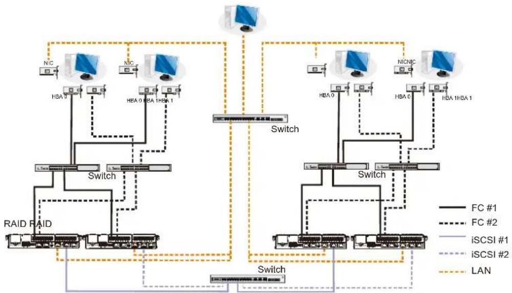
flowchart
graph TD
    A["RAID RAID"] --> B["Switch"]
    B --> C["HBA 0"]
    B --> D["HBA 1HBA 1"]
    B --> E["Switch"]
    E --> F["HBA 0"]
    E --> G["HBA 1HBA 1"]
    E --> H["Switch"]
    H --> I["HBA 0"]
    H --> J["HBA 1HBA 1"]
    H --> K["Switch"]
    K --> L["HBA 0"]
    K --> M["HBA 1HBA 1"]
    K --> N["Switch"]
    N --> O["HBA 0"]
    N --> P["HBA 1HBA 1"]
    N --> Q["Switch"]
    Q --> R["HBA 0"]
    Q --> S["HBA 1HBA 1"]
    Q --> T["Switch"]
    T --> U["HBA 0"]
    T --> V["HBA 1HBA 1"]
    T --> W["Switch"]
    W --> X["HBA 0"]
    W --> Y["HBA 1HBA 1"]
    W --> Z["Switch"]
    Z --> AA["HBA 0"]
    Z --> AB["HBA 1HBA 1"]
    Z --> AC["Switch"]
    AC --> AD["HBA 0"]
    AC --> AE["HBA 1HBA 1"]
    AC --> AF["Switch"]
    AF --> AG["HBA 0"]
    AF --> AH["HBA 1HBA 1"]
    AF --> AI["Switch"]
    AI --> AJ["HBA 0"]
    AI --> AK["HBA 1HBA 1"]
    AI --> AL["Switch"]
    AL --> AM["HBA 0"]
    AL --> AN["HBA 1HBA 1"]
    AL --> AO["Switch"]
    AO --> AP["HBA 0"]
    AO --> AQ["HBA 1HBA 1"]
    AO --> AR["Switch"]
    AR --> AS["HBA 0"]
    AR --> AT["HBA 1HBA 1"]
    AR --> AU["Switch"]
    AU --> AV["HBA 0"]
    AU --> AW["HBA 1HBA 1"]
    AU --> AX["Switch"]
    AX --> AY["HBA 0"]
    AX --> AZ["HBA 1HBA 1"]
The above diagram demonstrates how to utilize the iSCSI host ports for remote data replication.
The two hybrid systems, a source system (1) and a target system (2) reside within the same virtual pool but are physically apart. You want to create a volume copy/mirror pair for data protection, but do not want to rely on slow management LAN cable connections. In such case, you may link the hybrid systems using iSCSI host ports. If the distances between the enclosures are far, additional iSCSI switches (3) might be required in between.
The illustration above demonstrates how you can enjoy the full benefits of high-speed FC host link and management LAN connection, as well as a robust link for data protection (volume copy/mirror).
The SANWatch software suite, on which you configure the volume copy/mirror settings, will automatically detect the iSCSI data connection and will use it for data replication.
JBOD Connections
A SAS host link cable is included per JBOD. If you need to purchase other cables or if you need other cable(s) of different length, please contact your vendor.

WARNING
All SAS cables are sensitive and must be handled with care. To prevent interference within a rack system, the cable routing path must be carefully planned and the cables must not be bent.
Please contact your vendor for a list of compatible components!
JBOD SAS Expansion Configuration
The SAS expansion port connects to expansion JBOD enclosures. For Dual-Controller systems, each expansion port connects a controller to a corresponding JBOD controller making fault-tolerant links to different SAS domains.
The following principles apply to Storage System and JBOD connections:
- Dual-Controller Storage System System connects to Dual-Controller JBODs.
- Single-Controller Storage System System connects to Single-Controller JBODs.
- A longer cable is available for making expansion links with a Dual-Controller configuration. A longer cable is required if connections to JBODs are made from two opposite directions. Routing through two different connections can avoid loss of data links if one enclosure fails in between.
There is a rotary ID switch on every expansion enclosure that is manually configured using a flat blade screwdriver.
Configuring enclosure IDs:
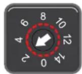
- The configurable IDs for JBODs are from 1 to 15. Usually the numbering starts from the one closest to the managing Storage System System.
- Make sure a unique ID is configured on each JBOD so that the SAS WWN addresses of disk drives can be properly assigned. Storage System system firmware automatically manages these addresses.
Configuration Rules
How to connect SAS interfaces across Storage System and JBOD enclosures:
- Fault-tolerant links in a Dual-Controller combinations: Corresponding to SAS drives' dual-ported interface, two physical links are available from each disk drive, routed across the backplane board, each through a SAS expander, and then interfaced through a 4x wide external SAS port.
- With data paths through separate SAS domains, access to disk drives can be continued in the event of a cable link or SAS JBOD controller failure.
| Designation | Description | Designation | Description |
| 1 | Controller A | 5 | Dual-ported SAS drives |
| 2 | Controller B | 6 | Expander |
| 3 | JBOD controller A | 7 | To another JBOD |
| 4 | JBOD controller B | ||
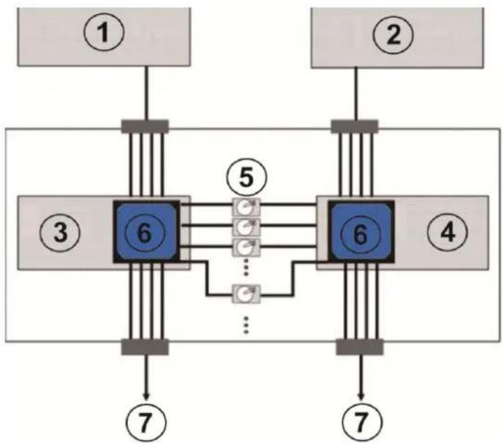
flowchart
graph TD
    A["①"] --> B["6"]
    C["②"] --> D["6"]
    B --> E["5"]
    D --> F["4"]
    B --> G["..."]
    D --> H["..."]
    B --> I["7"]
    D --> J["7"]
    style B fill:#000,stroke:#000,color:#fff
    style D fill:#000,stroke:#000,color:#fff
    style B fill:#999,stroke:#000,color:#fff
    style D fill:#999,stroke:#000,color:#fff
    style B fill:#999,stroke:#000,color:#fff
    style D fill:#999,stroke:#000,color:#fff
    style B fill:#999,stroke:#000,color:#fff
    style D fill:#999,stroke:#000,color:#fff
    style B fill:#ccc,stroke:#000
    style D fill:#ccc,stroke:#000
    style B fill:#ccc,stroke:#000
    style D fill:#ccc,stroke:#000
    style B fill:#ccc,stroke:#000
    style D fill:#ccc,stroke:#000
    style B fill:#ccc,stroke:#000
    style D fill:#ccc,stroke:#000
- Fault-tolerant Links to SAS disk Drives
- SAS expansion cables will be available with the JBODs. Note that if many JBODs are connected, a longer SAS external cable (e.g., a 120cm cable) may be necessary for connecting a JBOD from the opposite direction offering high redundancy.
- One expansion link connects JBODs from Storage System to the nearest JBOD, and then to the farthest JBOD. Another expansion link connects to the farthest JBOD from the opposite direction and then to the nearest JBOD.
- Each expander controller on the SAS JBOD controls a “SAS Domain” that connects one of the alternative interfaces on all of the disk drives in the enclosure. For example, one expander unit controls Domain A, and the other controls Domain B. In a fault-tolerant topology, the SAS external links always connect to the SAS ports on the same SAS Domain.
- The SAS Domains can be identified by the expanders' locations, i.e., upper controller slot (Controller A/Slot A) or the lower controller slot (Controller B/Slot B).
- On the Storage System system, each controller can be considered as managing a separate SAS Domain. With the help of the port selector mechanism on the MUX boards, the idea of SAS Domain applies even when SATA drives are used in a Dual-Controller JBOD.
Dual-Controller Expansion Connection
4016 / 4024 / 4024B models:
• Storage System Controller A: SAS exp. IN -> 1st JBOD Controller A: SAS exp. OUT
- 1^st JBOD Controller A: SAS exp. IN 2^nd JBOD Controller A: SAS exp. OUT
- 2^nd JBOD Controller A: SAS exp. IN 3^rd JBOD Controller A: SAS exp. OUT
- 3^rd JBOD Controller A: SAS exp. IN -> Last JBOD Controller A: SAS exp. OUT
- Storage System Controller B: SAS exp. IN -> Last JBOD Controller B: SAS exp. OUT
- Last JBOD Controller B: SAS exp. IN ->3^rd JBOD Controller B: SAS exp. OUT
- 3^rd JBOD Controller B: SAS exp. IN 2^nd JBOD Controller B: SAS exp. OUT
- 2^nd JBOD Controller B: SAS exp. IN 1^st JBOD Controller B: SAS exp. OUT
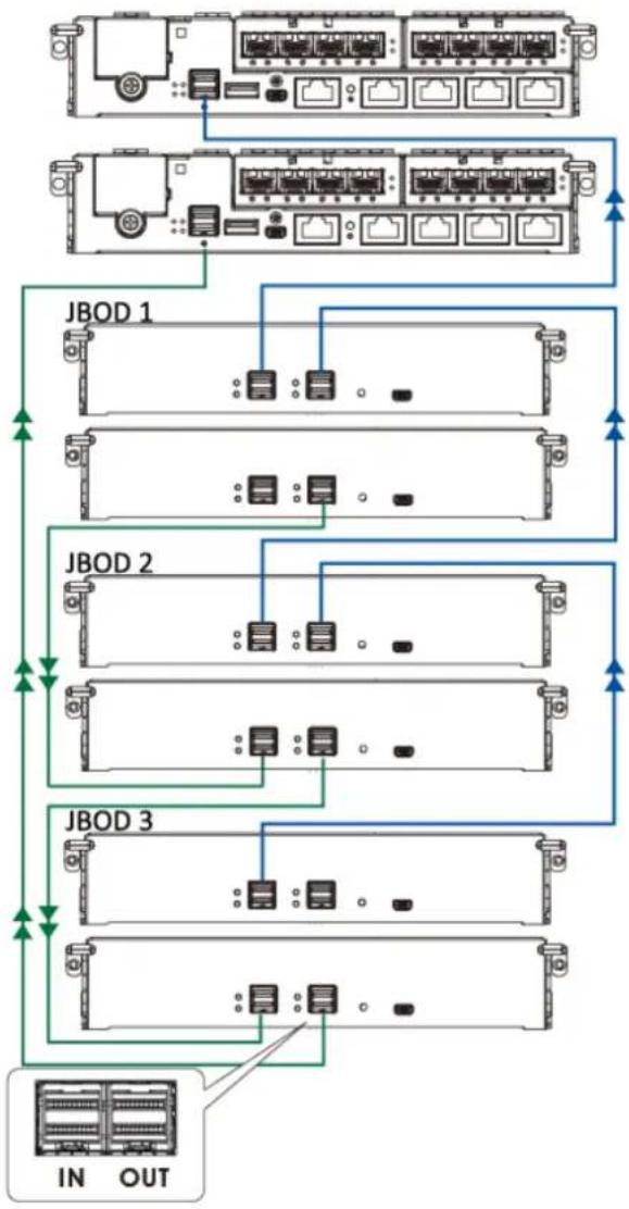
flowchart
graph TD
    A["In Line Port"] --> B["JBOD 1"]
    A --> C["JBOD 2"]
    A --> D["JBOD 3"]
    B --> E["Output"]
    C --> E
    D --> E
    style A fill:#f9f,stroke:#333
    style B fill:#ccf,stroke:#333
    style C fill:#ccf,stroke:#333
    style D fill:#ccf,stroke:#333
4016U / 4024UB models:
- RAID system top left SAS exp. IN -> 1st JBOD top SAS exp. OUT
- RAID system top right SAS exp. IN -> 2nd JBOD top SAS exp. OUT
- 1^st JBOD top SAS exp. IN 3^rd JBOD top SAS exp. OUT
- 2^nd JBOD top SAS exp. IN 4^th JBOD top SAS exp. OUT
- 2^nd last JBOD bottom SAS exp. OUT -> Bottom RAID left SAS exp. IN
- Last JBOD bottom SAS exp. OUT -> Bottom RAID right SAS exp. IN
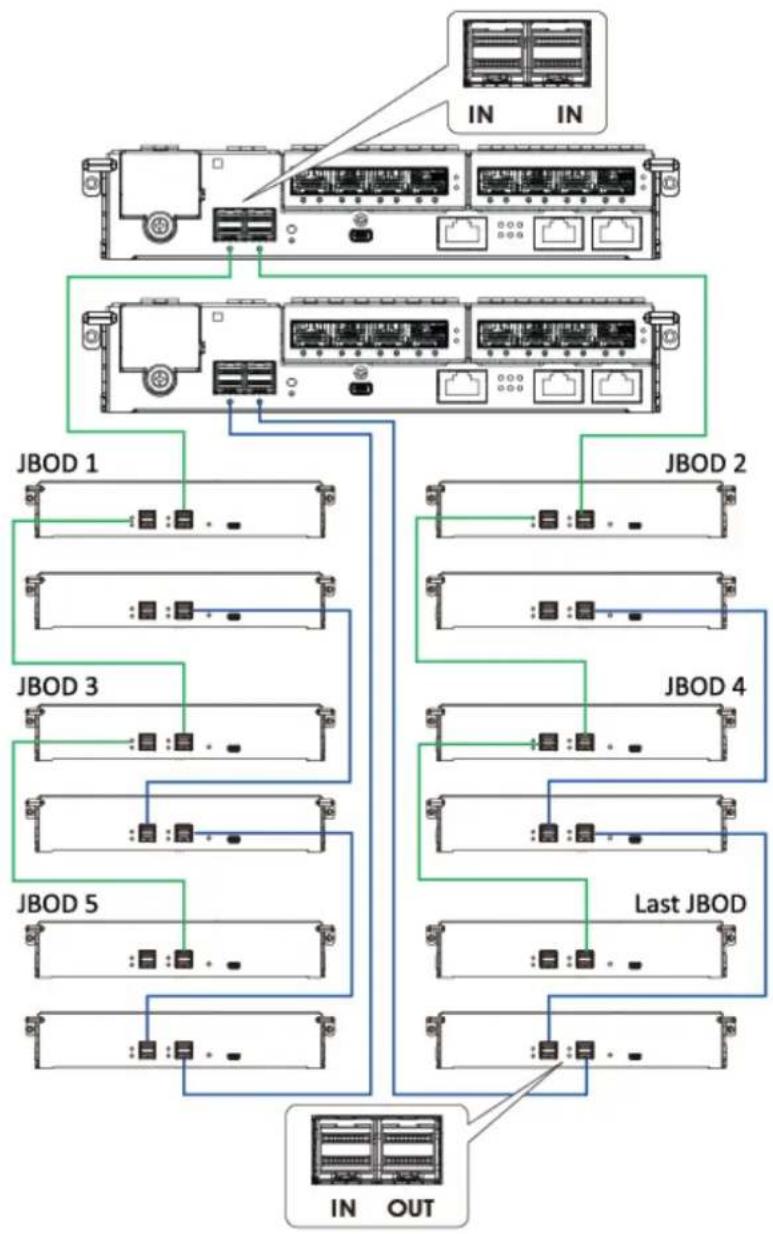
flowchart
graph TD
    A["In Out"] --> B["JBOD 5"]
    A --> C["JBOD 3"]
    A --> D["JBOD 1"]
    A --> E["JBOD 2"]
    A --> F["JBOD 4"]
    A --> G["Last JBOD"]
    B --> H["In Out"]
    C --> I["In Out"]
    D --> J["In Out"]
    E --> K["In Out"]
    F --> L["In Out"]
    G --> M["In Out"]
Single-Controller Expansion Connection
4016 / 4024 / 4024B models:
• Storage System System SAS exp. IN -> 1st JBOD SAS exp. OUT
- 1^st JBOD SAS exp. IN 2^nd JBOD SAS exp. OUT
- 2^nd JBOD SAS exp. IN 3^rd JBOD SAS exp. OUT
- 3^rd JBOD SAS exp. IN -> Last JBOD SAS exp. OUT
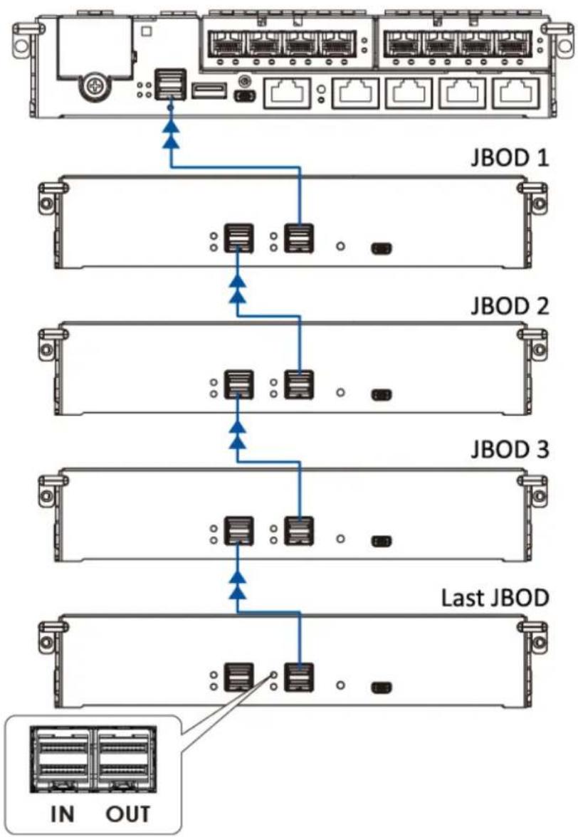
flowchart
graph TD
    A["Top Rack"] --> B["JBOD 1"]
    B --> C["JBOD 2"]
    C --> D["JBOD 3"]
    D --> E["Last JBOD"]
    E --> F["IN OUT"]
4016U / 4024UB models:
- RAID system top left SAS exp. IN -> 1st JBOD top SAS exp. OUT
- RAID system top right SAS exp. IN -> 2nd JBOD top SAS exp. OUT
- 1^st JBOD top SAS exp. IN 3^rd JBOD top SAS exp. OUT
- 2^nd JBOD top SAS exp. IN 4^th JBOD top SAS exp. OUT
.... and so forth!
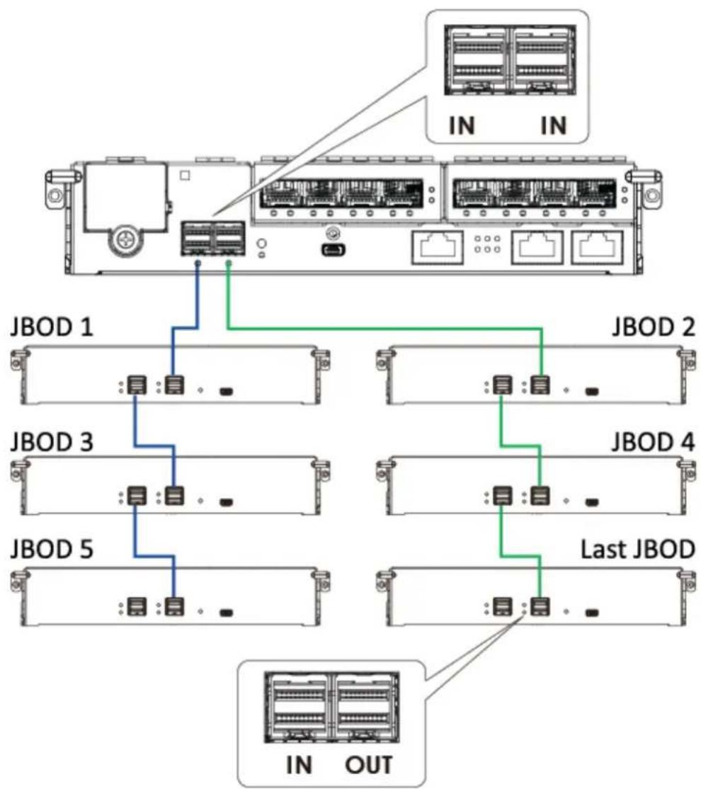
flowchart
graph TD
    A["Server chassis"] --> B["JBOD 1"]
    A --> C["JBOD 2"]
    A --> D["JBOD 3"]
    A --> E["JBOD 4"]
    A --> F["JBOD 5"]
    A --> G["Last JBOD"]
    A --> H["IN OUT"]
    style A fill:#f9f,stroke:#333
    style B fill:#bbf,stroke:#333
    style C fill:#bbf,stroke:#333
    style D fill:#bbf,stroke:#333
    style E fill:#bbf,stroke:#333
    style F fill:#bbf,stroke:#333
    style G fill:#bbf,stroke:#333
    style H fill:#bbf,stroke:#333
Management Console Connections
4016 / 4024 / 4024B models:
| Designation | Description | Designation | Description |
| 1 | Serial port (for Telnet access) | 4 | Local area network |
| 2 | DB9 to mini USB | 5 | Management Software / telnet |
| 3 | CAT5e LAN cable | 6 | Mini USB port (Console port) |
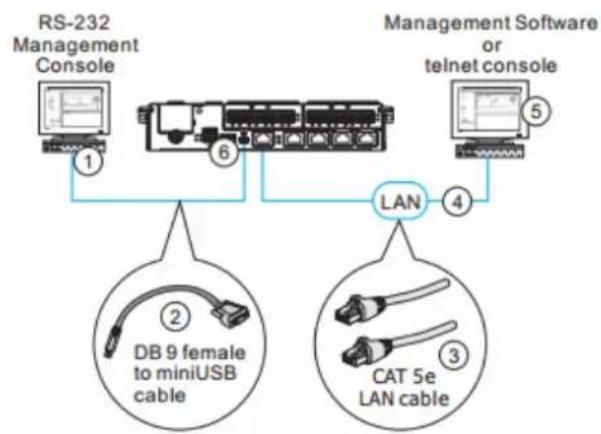
flowchart
graph TD
    A["RS-232 Management Console"] -->|1| B["LAN"]
    C["Management Software or telnet console"] -->|5| B
    B -->|4| D["DB 9 female to miniUSB cable"]
    B -->|3| E["CAT 5e LAN cable"]
4016U / 4024UB models:
| Designation | Description | Designation | Description |
| 1 | Serial port (for Telnet access) | 4 | Local area network |
| 2 | DB9 to miniUSB or Y-cable | 5 | SANWatch/ telnet console |
| 3 | CAT5e LAN cable |
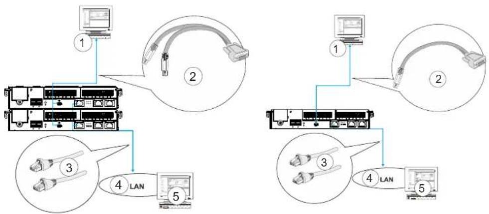
flowchart
graph TD
    A["1"] --> B["2"]
    B --> C["3"]
    C --> D["4 LAN"]
    D --> E["5"]
    F["1"] --> G["2"]
    G --> H["3"]
    H --> I["4 LAN"]
    I --> J["5"]
Y-cable management connection
DB9 to miniUSB cable management connection
Connecting Storage System System to external consoles
Serial port (mini USB): Use the cable supplied with the system to connect to mini USB port.
Ethernet port: An Ethernet cable should be supplied by the user.

NOTE
A null modem may be required if you are using a 3^rd party cable.
The serial port's defaults are:
| Baud Rate | 38400 |
| Data Bit | 8 |
| Parity | None |
| Stop Bit | 1 |
| Flow Control | Hardware |
For TCP/IP connection and firewall configuration please refer to Management Software online help or User's Manual. If your network environment is not running DHCP server protocols, a default IP, <10.10.1.1> can be used if you are accessing for the first time.
Power Connections
Once all hard drives have been properly installed and the I/O ports or management interfaces have been connected, the system can be powered on.
Checklist
BEFORE powering on the system, please check the following:
- Hard drives: Hard drives are correctly installed in the drive trays.
- Drive trays: All the drive trays, whether or not they contain a hard drive, have been installed into the system.
- Cable connections: The system has been correctly connected to host computer(s), management computers, or external networking devices.
- Ambient temperature: Make sure the surrounding environment temperature is not higher 35 degrees Celsius (with CBM).

NOTE
Make sure you use the power cables provided that are at least 1.2 meters in length. DO NOT use extension cables as the power cables are designed to connect ONLY and DIRECTLY to relocatable power taps (RPTs) on server cabinets.
Power Cords Connections
Use the included cables. Connect them to the power sockets (in blue) for all PSUs.
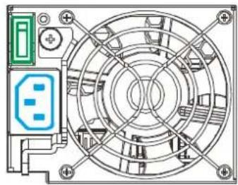
natural_image
Technical line drawing of a mechanical fan or electrical connector with mounting holes and internal components (no text or symbols)Power On Procedure
Before you power on the Storage System System, please power on the expansion enclosure JBOD first if your network configuration has multiple arrays.
To power on the system please follow the procedures below.
- Turn on the power switches to the "on" position for every PSUs (shown in blue).
- Power on the networking devices, e.g. switches.
- Power on the host computers. They should be the last devices to be turned on.
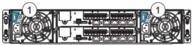
natural_image
Back view of a server rack with multiple ports and connectors (no visible text or labels)2U System
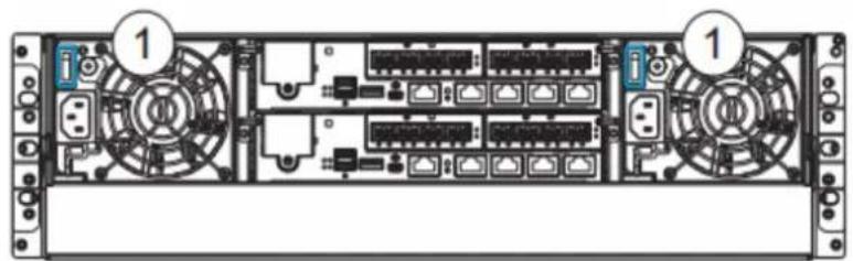
text_image
Diagram of a server rack with labeled ports and connectors, showing internal components and numbered indicators.3U System

Make sure all power supply modules' switches are turned on!
Power On Status Check
As a general rule, once the system has been powered on, there should NOT be LED(s) that light up amber nor should you hear an audible alarm from the system. You may verifying system statuses via the following monitoring interfaces: LEDs on rear chassis, including controller module, PSUs, and cooling modules (refer to System Monitoring).
PSU & Cooling Module LEDs:
PSU LED (1):
| On | Green |
| Failure | Amber |
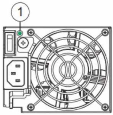
natural_image
Diagram of a computer power supply unit showing fan layout and terminal connections (no text or labels)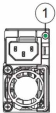
text_image
1Power Off Procedure
If you wish to power down the system, please follow these steps:

NOTE
If you wish to power down the system, please ensure that no time-consuming processes, like “Regenerate Logical Drive Parity” or a “Media Scan,” are taking place.
1. Stop I/O access to the system
Close your applications running on the host computers to stop all I/O access to the system.
2. Flush the cache
Locate the C_Dirty LED (refer to Storage System System Controller LEDs) on the controller module to check if there is still cached data in the DRAM (if the LED is lid up in amber).
- Use the Shutdown Controller function to flush all cached data (please refer to the SANWatch manual)
- Once the cache has been flushed, you may proceed to power down the system.
System Monitoring
The EonStor DS series is equipped with a variety of self-monitoring features that help keep system managers aware of system operation statuses.
Monitoring Features
You may monitor the system through the following features:
- Firmware: The controller in the system is managed by a pre-installed firmware, which is accessible in a terminal program via the serial port. For more details, see the Firmware manual in the CD-ROM.
- SANWatch: SANWatch is a browser-based Graphical User Interface (GUI) for configuration, management, and monitoring of the internal storage array of EonServ. For more details, please refer to manuals on the CD-ROM.
- LEDs: LED indicators notify users of system status, events, and failures. LEDs are located on both the front and rear panel of the chassis. For details, see and subsequent sections.
- Audible alarm: Audible alarm will be triggered in case of system failures.
LED Panel
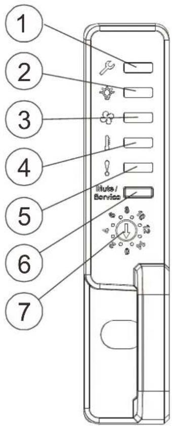
text_image
1 2 3 4 5 6 7 Mute/Service| Name | Color | Status |
| 1. Service | White | White indicates that the system is being serviced or is requiring services.OFF indicates that the system is not being serviced nor is requiring services. |
| 2. Power | Green/Amber | Green indicates that the system is powered properly.Amber indicates that there is a power failure in the system. |
| 3. Cooling fan | Green/Amber | Green indicates that the cooling fan is operating properly.Amber indicates that the there is a coolingfan failure in the system. |
| 4. Thermal | Green/Amber | Greenindicates that the internal temperature is within the safety threshold.Amberindicates that the internal temperature has gone over the safety threshold. |
| 5. System fault | Green/Amber | Greenindicates that the system is operating normally.Amberindicates that the system has encountered abnormal conditions: |
| 6. Mute/ service button | N/A | Pressing less than one secondmutes the audible alarm.Pressing more than two seconds sends a service notification to the host computer. |
| 7. Rotary ID switch | N/A | Allow users to set enclosure IDs when connected to JBOD expansion enclosure(s). |
When lid amber to indicate failure, please check the corresponding module(s). For example, if the Thermal LED lights up amber, please check if there are faults on the system cooling modules (built within the PSU) or the drawer fans.
Drive Tray LED
Two LED indicators are located on the right side of each drive tray. When notified by a drive failure message, you should check the drive tray indicators to find the correct location of the failed drive.
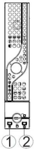
text_image
Diagram of a device control panel with labeled parts and numbered indicators2.5"
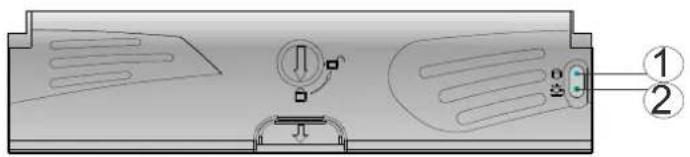
text_image
Technical diagram of a device casing with labeled parts and directional arrows indicating motion or movement.3.5"
| Name | Color | Status |
| 1. Drive Busy | Blue | Flashing Blue indicates data is being written to or read from the drive. The drive is busy.Steady Blue indicates that a hard drive is plugged-in but there is no activity on the disk drive. |
| 2. Power Status | Green / Red | Green indicates that the drive bay is populated and is working normally.RED indicates that the disk drive has failed, or a connection problem occurred. |
Storage System System Controller LEDs
4016 / 4024 models:
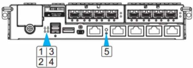
text_image
1 3 2 4 5| Name | Color | Status |
| 1. C_Dirty | Amber | Amberindicates the following:- Cache Memory is dirty.- Data in flash backup module is being flushed to cache.- Errors occurred with cache memory (ECC errors).- Data is being flushed from flash backup module to drive (when power is restored).- Supercapacitor temperature reading is abnormal (out of the 0 to 35°C range).- Supercapacitor is not present.OFFindicates that the cache is clean, and that the Super capacitor is capable of sustaining memory in case of power loss.Blinking Amberindicates cached data is being transferred to the flash module after the occurrence of a power outage. Once the transfer is done, all LEDs will turn off.This signal is local to each controller. |
| 2. Host Busy | Green | Blinking Green to indicate traffic on the host bus. |
| 3. Ctrl Status | Green/Amber | Green indicates that a controller is operating healthily.Amber indicates that a component failure has occurred, or inappropriate RAID configurations have caused system faults. It is also lit during the initialization process. |
| 4. CBM Status | Green/Amber | Green steady on indicates the CBM module is ready. Both supercapacitor and flash modules are present.Amber steady on indicates CBM failure, meaning either super capacitor or flash has failed. When lit, it also indicates either super capacitor or a flash is missing.Blinking means the super capacitor is being charged. |
| 5. Restore default | Green | Lights up Green after pressing and holdingRestore default button to indicate a successful reset. |
4016U / 4024UB models:
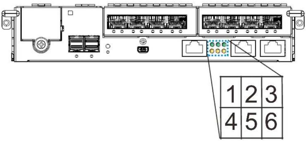
text_image
1 2 3 4 5 6| Name | Color | Status |
| 1. Ctrl Status | Green/Amber | Green indicates that a RAID controller is operating healthily.Amber indicates that a component failure has occurred, or inappropriate RAID configurations have caused system faults. It is also lit during the initialization process. |
| 2. C_Dirty | Amber | Amber indicates the following:- Cache Memory is dirty.- Data in flash backup module is being flushed to cache.- Errors occurred with cache memory (ECC errors).- Data is being flushed from flash backup module to drive (when power is restored).- Battery voltage is lower than 2.5V.- Battery temperature reading is abnormal (out of the 0 to 45°C range).- Battery is not present.OFF indicates that the cache is clean, and that the battery backup unit is capable of sustaining memory in case of power loss.Blinking Amber indicates cached data is beingtransferred to the flash module after the occurrence of a power outage. Once the transfer is done, all LEDs will turn off.This signal is local to each controller. |
| 3. Temp. | Amber | Amberindicates that the detectedCPU/board/chassis temperature has exceeded the higher temperature threshold.OFFindicates that the detected temperature reading is within the safe range. |
| 4. CBM Status | Green/Amber | Greensteady on indicates the CBM module is ready. Both a BBU and flash modules are present.Ambersteady on indicates CBM failure, meaning either BBU or flash has failed. When lit, it also indicates either BBU or a flash is missing in a redundant-controller system.Blinkingmeans a BBU is being charged.OFFmeans BBU is not installed in a single-controller “G” model. |
| 5. Hst Bsy | Green | Blinking Greento indicate traffic on the host bus. |
| 6. Drv Bsy | Green | Blinking Greento indicate traffic on the drive channels. |
| 7. Restore Default | Green | Greenindicates the RAID configuration default has been successfully restored. The LED state will be invalidated after a few seconds. |
1G iSCSI/Ethernet Management Port LEDs
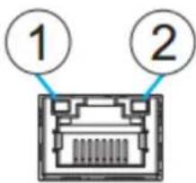
text_image
① ②| Name | Status | Description |
| 1. Speed | ON | Indicates 1Gb connection is established. |
| Off | Indicates 10/100Mb connection is established or no connection established. | |
| 2. Link / Active | ON | Indicates a connection has been established. |
| FLASHING | Indicates data transmitting. | |
| OFF | Indicates connection is not established. |
*1G iSCSI/Ethernet Management needs to be connected with a RJ-45 Connector.
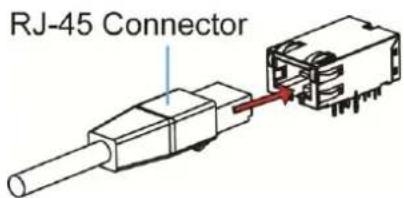
text_image
RJ-45 Connector12G SAS Expansion Port LEDs
Link
| Name | Status | Description |
| Link / Active | ON | Indicates that all 4 PHYs are validly linked. |
| FLASHING | Indicates less than 4 PHY links are connected (at least one 1 of the 4 PHYs links has failed). | |
| OFF | Indicates all 4 PHYs links are offline. |
*The 12G SAS Expansion Port is connected through the SAS Connector.
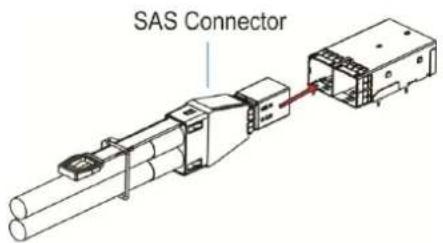
text_image
SAS Connector10G Ethernet Host Board Port LEDs
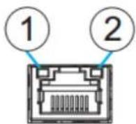
| Name | Status | Status |
| 1. Speed | Green | Indicates 10Gb connection is established. |
| Amber | Indicates 1Gb connection is established. | |
| OFF | Indicates 10/100Mb connection is established. | |
| 2. Link / Active | ON | Indicates a connection is established. |
| Flashing | Indicates data transmitting. | |
| OFF | Indicates connection is not established. |
*The 10G Ethernet Port needs to be connected with a RJ-45 connector.
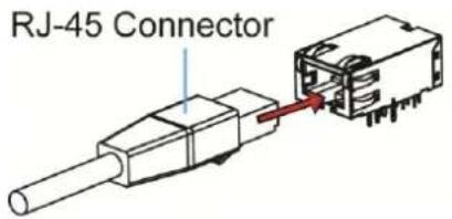
text_image
RJ-45 Connector10G iSCSI Host Board Port LEDs (RJ-45)
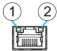
| Name | Status | Status |
| 1. Speed | Green | Indicates 10Gb connection is established. |
| Amber | Indicates 1Gb connection is established. | |
| OFF | Indicates 10/100Mb connection is established. | |
| 2. Link / Active | ON | Indicates a connection is established. |
| Flashing | Indicates data transmitting. | |
| OFF | Indicates connection is not established. |
*The 10G iSCSI Port needs to be connected with a RJ-45 connector.
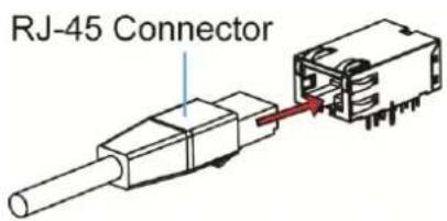
text_image
RJ-45 Connector10G iSCSI Host Board Port LEDs (Fibre)

text_image
CH0 CH1 LED| LED status | Color | Status |
| Steady On | Green | Indicates a link has been established. |
| Flashing | Green | Indicates an active link. |
| Off | Off | Indicates a link has not been established. |
*The 10G iSCSI Fibre Channel Port is connected with a SFP+ Transceiver with FC Fibre connector attached to it. To install Fibre cable, please refer to Fibre Cabling.
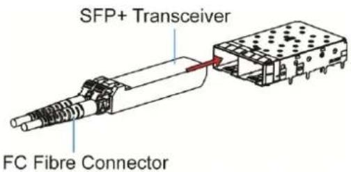
text_image
SFP+ Transceiver FC Fibre Connector40G iSCSI Host Board Port LED's
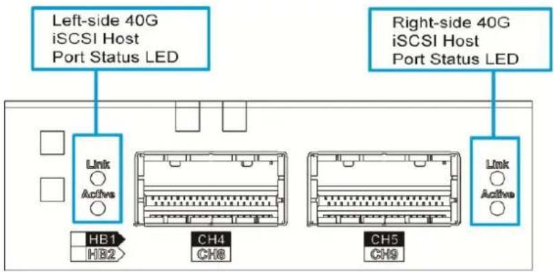
text_image
Left-side 40G iSCSI Host Port Status LED Right-side 40G iSCSI Host Port Status LED Link Active HB1 HB2 CH4 CH8 CH5 CH9 Link Active| Name | Status | Description |
| 1. Link | Green | Indicates an established connection |
| OFF | Indicates that connection is not established. | |
| 2. Active | ON(Amber) | Indicates 40Gb connection is established. |
| FLASH(Amber) | Indicates data transmitting. | |
| OFF | Indicates that connection is not established. |
*The 40Gb iSCSI Host Board port is connected through the QSFP connector as below picture shown:
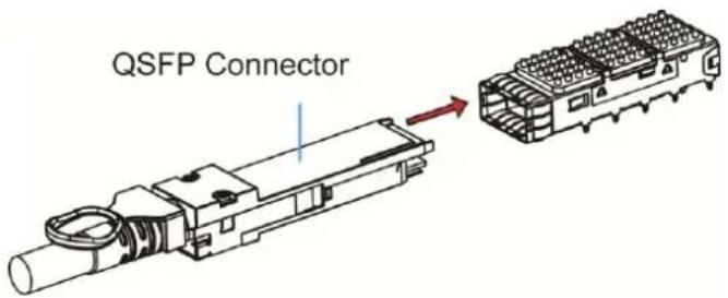
text_image
QSFP Connector16G Fibre Channel Host Board Port LEDs

text_image
1 2| Name | Status | Description |
| 1. Link / Active | ON | Indicates an established connection. |
| FLASHING | Indicates data transmitting. | |
| OFF | Indicates that a connection is not established. | |
| 2. Speed | Green | Indicates a 16Gb connection is established. |
| Yellow | Indicates an 8Gb connection is established. | |
| OFF | Indicates a 4Gb or slower connection is established. |
* The 16G Fibre Channel Port is connected with a SFP Transceiver with FC Fibre connector attached to it. To install Fibre cable, please refer to Fibre Cabling.
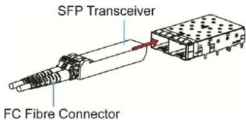
text_image
SFP Transceiver FC Fibre Connector8G Fibre Channel Host Board Port LEDs
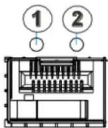
text_image
① ②Each controller module houses Fibre channel host ports. Each of these ports has two LEDs for displaying the operating status.
| Name | Status | Description |
| 1. Link / Active | ON | Indicates an established link. |
| OFF | A link is broken. | |
| 2. Speed | Green | Indicates an 8Gb connection. |
| Amber | Indicates a 4Gb connection. | |
| OFF | Indicates a 2 Gb or no connection. |
For systems that come with 8Gb Fibre channel host ports. They deliver fast I/O performance for Storage Area Network (SAN) applications. Optical cables can be used over distances and have been shown to be more reliable. Due to the demands of high transfer rates, optical cables are preferred for 8/4Gbps fiber connectivity. Optical cables are not susceptible to EMI.
*The 8G Fibre Channel Port is connected with a SFP Transceiver with FC Fibre connector attached to it. To install Fibre cable, please refer to Fibre Cabling.
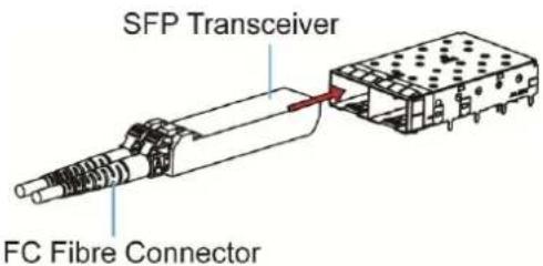
text_image
SFP Transceiver FC Fibre ConnectorSFP+ On-Board and Converged Host Board Port LED's
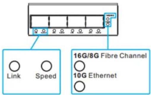
text_image
16G/8G Link Speed 16G/8G Fibre Channel 10G Ethernet| Name | Status | Description |
| 16G / 8G Fibre Channel | On (Green) | Indicates 16G Fibre Channel mode |
| 16G / 8G Fibre Channel | On (Amber) | Indicates 8G Fibre Channel mode |
| 10G Ethernet | On (Green) | Indicates 10G Ethernet mode |
| Name | Status | Description | ||
| Link | On (Green) | Indicates an established link. | ||
| Off | Indicates a broken link. | |||
| Name | Status | 16G Fibre Channel | 8G Fibre Channel | 10G Ethernet |
| Speed | On (Green) | 16G FC | 8G FC | 10G Ethernet |
| On (Amber) | 8G FC | 4G FC | ---- | |
| Off | 4G FC or no link | 2G FC or no link | No link | |
*The SFP+ On-Board and Converged Host Board port is connected with a SFP
Transceiver with FC Fibre connector attached to it. To install Fibre cable, please refer to Fibre Cabling.
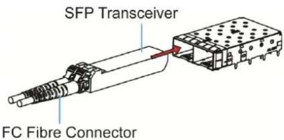
text_image
SFP Transceiver FC Fibre ConnectorInfiniBand Host Board Port LED's
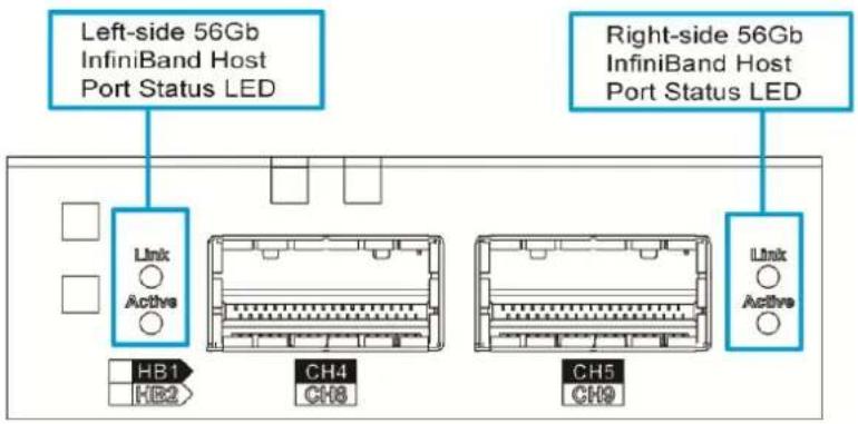
text_image
Left-side 56Gb InfiniBand Host Port Status LED Right-side 56Gb InfiniBand Host Port Status LED Link Active HB1 HB2 CH4 CH8 CH5 CH9 Link Active| Name | Status | Description |
| 1. Link | Green | Indicates an established connection |
| OFF | Indicates that connection is not established. | |
| 2. Active | ON(Amber) | Indicates 56Gb connection is established. |
| FLASH(Amber) | Indicates data transmitting. | |
| OFF | Indicates that connection is not established. |
*The InfiniBand Host Board port is connected through InfiniBand connector as below picture shown:
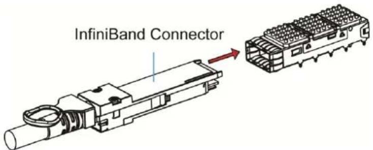
text_image
InfiniBand Connector12G SAS Host Board LED
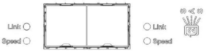
text_image
Link ○ Speed ○ ○ Link ○ Speed| LED | Color | Status |
| 1. Link status LED | Green | Green indicates a connection has been established.Off indicates connection not established. |
| 2. Speed LED | Green / Amber | Green indicates 12Gb connection established.Amber indicates 6Gb connection established.Off indicates no connection established. |
*The 12G SAS Host Board is connected through the SAS Connector.
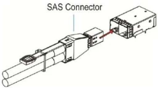
text_image
SAS ConnectorController LED for 12G SAS JBOD Models

text_image
IN OUT IN OUT 1 OUT 2 Link Link Link Speed Speed Speed Speed SpeedJB 3000 series
JB 3060L series
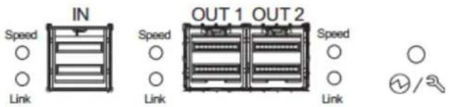
text_image
IN Speed Link OUT 1 OUT 2 Speed Link Speed Link ②/2JB 3060 series (3 drawer)
| Name | Status | Description |
| Link / Active | ON | Indicates all 4 PHYs are validly linked. |
| FLASHING | Indicates one of the 4 PHYs links has failed. | |
| OFF | Indicates all 4 PHYs are offline. | |
| Speed | Green | Indicates 12Gb link speed. |
| Amber | Indicates 6 / 3Gb link speed. | |
| OFF | Indicates no connection. | |
 | Green | Indicates the controller is operating normally. |
| Amber | Indicates a component failure has occurred. It is also lit during the initialization process. |
*The 12G SAS JBOD Models Port is connected through the SAS Connector.
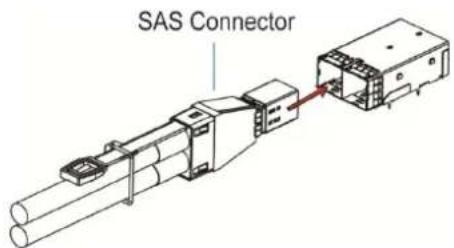
text_image
SAS ConnectorPSU & Built-in Cooling Module LEDs
The PSU (Power Supply Unit) contains the LEDs for the PSU and the cooling module statuses. When either of the unit fails, you need to replace the PSU as soon as possible. For details, please refer to Replacing the Power Supply Module.
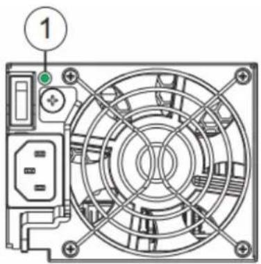
natural_image
Technical line drawing of a computer power supply unit with fan and socket (no text or symbols)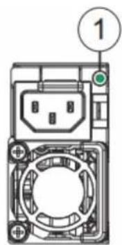
text_image
1PSU & Cooling Module Status LED (1)
| Status | Description |
| Flashing (Green) | The system is connected to power supply but the power switch has not turned on. |
| On (Green) | The PSU / cooling module is operating normally. |
| On (Amber) | The PSU / cooling module is faulty. |

WARNING
HAZARDOUS MOVING PARTS!
KEEP FINGERS AND OTHER BODY PARTS AWAY!
Alarms and I2C Bus
Other monitoring schemes include audible alarms and I ^2 C bus.
Audible Alarms
If any of the following components fails, the audible alarm will be triggered:
- Cooling fan modules
- PSU modules
- CBM module
- Hard disk drives
- Sensors or presence detection circuitries
If an alarm rings out, the administrator must read the error message on the terminal or SANWatch screen to determine what has triggered the alarm, and then take appropriate actions to rectify the problem. The alarm can be turned off using the mute button on the front panel and the Alarm beep pattern is described in the Troubleshooting Guide included in the CD-ROM.

NOTE
When temperature exceeds a preset threshold, the controller's charger circuits will stop charging. You will then receive a message that reads "Thermal Shutdown/Enter Sleep Mode." When the temperature falls back within normal range, the super capacitor will resume charging.
l^2C
The operating status of PSU and cooling fan modules are collected through an I ^2 C serial bus. If either of those modules fails, the failure will be detected and you will be notified through the same methods as in the audible alarms.
System Maintenance

WARNING
Do not remove a failed component from the system until you have a replacement on hand. If you remove a failed component without immediate replacement, it will disrupt the internal airflow.
Qualified engineers who are familiar with the system should be the only ones who make component replacements.
When inserting a removable module, do not use excessive force. Forcing or slamming a module can damage the connector pins either on the module itself or on the backplane.
The following components can be replaced:
- Controller module (please refer to Replacing the Controller Module)
- Memory module (please refer to Replacing Memory Module(s))
- CBM module (please refer to Replacing the Cache Backup Module (CBM))
- Host board (please refer to Replacing the Controller Host Board)
- PSU module (please refer to Replacing the Power Supply Module)
- Hard drive (please refer to Replacing the Hard Disk Drive)
Restoring Default System Settings

NOTE
Restoring default settings is a last-resort function. All configurations, such as parameters and host LUN mappings, will be erased.
You may need to restore default settings in the following cases:
- When the firmware update procedure requires it.
- When you need to reset the password to access the Storage System system.
Restoring Default Settings
To restore default settings for Dual-Controller models, follow these steps.
- Stop all host I/O's.
- Save the current configuration using the "Export NVRAM" function.
- You may also want to make a list of the existing ID/LUN mapping information because the default restoration will erase the ID/LUN mapping associations (e.g., which logical drive is associated with which host ID/LUN)
- Remove Controller B from the chassis. Please refer to Removing the Controller.
- Power off the Storage System system.
- Press and hold the Restore Default button on Controller A. You may use a straightened paper clip to press the button. While pressing the Restore Default button down, power on the Storage System system.
- Keep pressing the Restore Default button till the Restore Default LED lights up than release the Restore Default button.
- System default has been restored when the Controller Status LED changes the color from amber to green.
*The Single-Controller system's restore default procedure is complete and for Dual-Controller systems, please continue with the following procedures:
-
Power off the system.
-
Replace Controller A with Controller B (Controller B will be inserted into Controller A's slot) While leaving Controller B slot empty with Controller B in slot A, perform the above steps 1 to 8 to restore Controller B to default settings.
-
Put both Controller A and Controller B into their original positions and power up the system.
Replacing the Storage System System Controller
Module(s)

WARNING
Controller firmware MUST be identical for proper functionality.
DO NOT mix controller modules from different models. Each controller has a unique ID which is applied to host port names. As the result, you may encounter SAN problems with identical port names on multiple systems.
When removing a controller from a Single-Controller system, ensure that your applications have been shut down beforehand.
Controller firmware MUST match so before you replace a controller in a dual-controller system, please check if the firmware of the operational controller matches the replacement controller sent to you. The replacement controller sent to you will state its firmware version with a label on the packaging. To find out the firmware version of your operating controller, use Storage Manager > Information > Enclosure View in SANWatch (please refer to the SANWatch Manual for details).
To update the firmware, please refer to the following:
a. SANWatch User Manual on Upgrading the Firmware
b. Firmware Manual on System Functions: Upgrading Firmware
- Prepare a clean, static-free work pad or container to place the controller.
- (Replacing Single-Controller models or both controllers simultaneously) Shut the system down. Stop all I/O access to the system and make sure all cached writes have been distributed to disk drives using firmware's Main Menu -> System Functions > Shutdown controller function. Power off the system and turn off the power switches and unplug the power cords from PSUs.
- Disconnect all cables that are connected to the controller module.
- Loosen the screw that secures the control module's ejection levers.
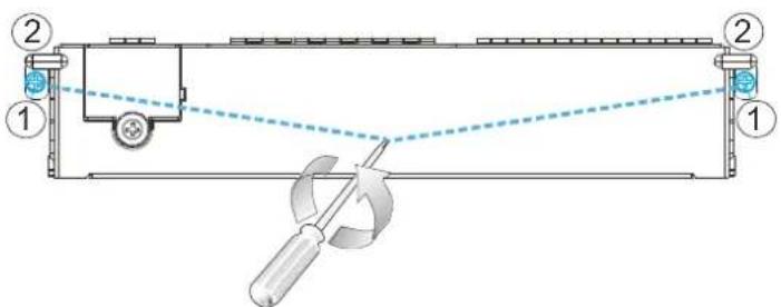
text_image
Technical diagram showing a mechanical setup with labeled components and a tool interacting with a curved component.- Push the ejection levers downwards (indicated by the blue arrows). The controller module will automatically ease out of the controller module bay.
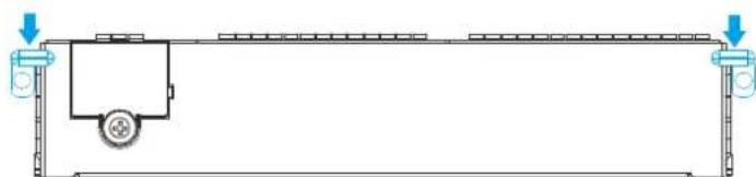
natural_image
Pure technical diagram of a mechanical assembly with no text, numbers, or symbols- Insert the new controller module. Carefully push the controller until you feel the contact resistance when the board edge connectors are engaging the backplane. Push the ejection levers upward (indicated by the blue arrows) and fasten the retention screw on the ejection levers.
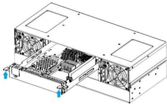
natural_image
Technical line drawing of a computer tower drive showing internal components and fan array (no text or labels)-
Reattach all the cables.
-
For Single-Controller models or when replacing both controllers simultaneously, power up the system. Check system message on the LCD screen, SANWatch, or firmware menu-driven utility. When the replacement controller is successfully brought online, the Power On Status LEDs should turn on properly.
-
For Single-Controller models or replacing both controllers simultaneously, Restoring NVRAM data. To restore previous ID/LUN mapping settings, users may use the following options:
- Use the "Restore NVRAM from Disks" or "Restore NVRAM from Files" functions in the firmware. ID/LUN mapping will be restored.
Replacing the Host Board
To replace the existing host board, loosen the thumb screw and push the release lever to detach the host board from the controller.
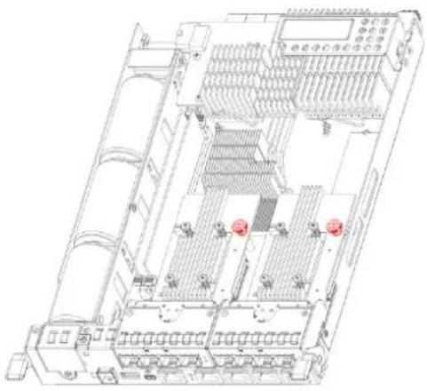
natural_image
Technical line drawing of an electronic device chassis with multiple ports and connectors (no text or symbols)Thumb screw (red)
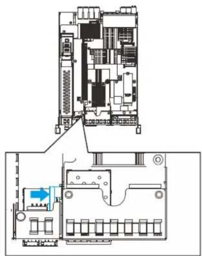
natural_image
Technical diagram of an electronic device layout showing top and side views with no visible text or symbolsRelease lever
By holding onto the edges of the PCB and using the guide pin (shown below in blue) for positioning, lower the replacement host board into the controller. Tighten the thumb screw to complete the installation. Reinsert the controller back into the system.
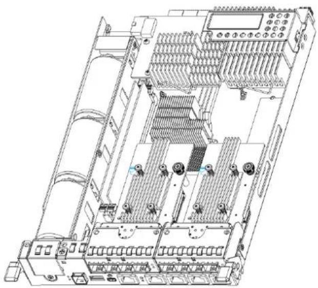
natural_image
Technical line drawing of an electronic device chassis with multiple ports and connectors (no text or symbols visible)Replacing Memory Module(s)
The controller comes with pre-installed DRAM module(s). You may upgrade it or replace it when the original module malfunctions (shown as the "NVRAM failure" event in SANWatch). If you have two modules installed, please identify correctly which one has failed before proceeding with the replacement procedure!

WARNING
If you are installing only one or replacing just one DRAM module, with the I/O ports pointing at you, always install to the DRAM slot on the right (blue slot). Follow the ESD Precautions (refer to ESD Precautions). Contact your system vendor for selecting a compatible DRAM module. Reusing the DRAM module removed from a failed controller is not recommended unless you have a similar Storage System system to test its integrity.
Installing the DIMM Module
- Remove the controller module (refer to Replacing the Controller Module).
- Wait for one minute for the remaining electricity on the main board to disperse.
- Push down the clips on the sides of the DIMM socket The DIMM will eject automatically from the socket.
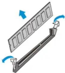
natural_image
Diagram of a mechanical component with arrows indicating motion, no text or symbols present- Insert the replacement module. Make sure the side clips are in the open positions. Align the DIMM module with the socket and firmly push the DIMM module into the socket. The side clips will close automatically and secure the DIMM module into the socket.

natural_image
Diagram of a mechanical assembly with rotating components and blue arrows indicating motion (no text or symbols)- Reinstall the controller module into the chassis (refer to Replacing the Controller Module).
Replacing the Cache Backup Module (CBM)

WARNING
Make sure you have the correct replacement module(s): Supercapacitor or / and Flash Backup Module (FBM) on-hand before you attempt to replace the CBM.
Supercapacitor Fault Conditions and Precautions
If a Supercapacitor leaks, gives off a bad odor, generates heat, becomes discolored or deformed, or in any way appears abnormal during use, recharging or storage, immediately remove it from the system and stop using it. Here are some of the conditions that might trigger Supercapacitor fault.
- The temperature sensor on the system's charger circuit reports a temperature reading exceeding the pre-set threshold. The charger circuits will enter a low-power and self-protection state.
- A Supercapacitor module has been charged for more than 10 minutes. A timer is embedded with the charger. When this occurs, the charger will enter a timer fault state. Charging will resume automatically after you remove/re-install the Supercapacitor module or reset the system.
Follow these precautions when you install the Supercapacitor.
- Use the replacement Supercapacitor supplied by your distributor. Use of capacitors provided otherwise will void your warranty.
- Dispose of used Supercapacitor at authorized battery disposal sites only.
- Do not place a Supercapacitor near a heat source.
- Do not immerse the Supercapacitor in water or expose it to other forms of liquids.
- Do not disassemble or modify the Supercapacitor.
- Do not pierce the Supercapacitor with a sharp object, strike it with a hammer, exert pressure on it, or throw it.
Replacing the Supercapacitor
To replace the Supercapacitor, follow these steps:
- Remove the controller module (refer to Replacing the Controller Module).
- Disconnect the 4-pin Molex connector from the charge board (1).
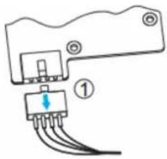
natural_image
Pure electrical connector diagram without any text, numbers, or symbols- Loosen the screw (2) at the end of the Supercapacitor.
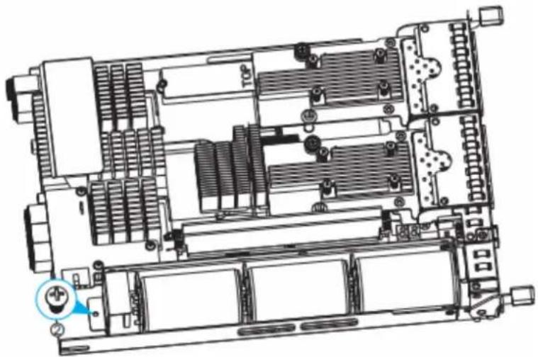
natural_image
Technical diagram of an internal server rack with heat sinks and connectors (no text or labels)-
Lift the Supercapacitor from the screw end at 45 degree angle and remove it out of the controller chassis.
-
Insert the replacement Supercapacitor at a 45 degree angle; make sure the protrusion (1) meets at the front of the Supercapacitor. Secure the Supercapacitor with the screw (2) once it is in place.
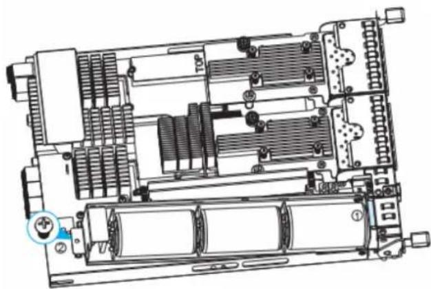
natural_image
Technical diagram of an internal electronic device with cooling fans and heat sinks (no text or labels)- Connect the 4-pin Molex connector of the Supercapacitor to the charge board connector (3).
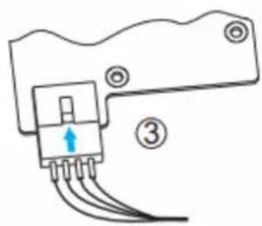
natural_image
Pure electrical connector diagram without any text, numbers, or symbols- Reinstall the controller.
Replacing Flash Backup Module (coupled with Supercapacitor)
Up to two flash backup modules can be installed. If there are two host boards installed, to gain access to the FBMs will require the user to remove the second host board. Once the second host board has been removed, please read the following instructions to replace the flash backup module:
-
Remove the controller module (refer to Replacing the Controller Module).
-
Locate the flash backup module.
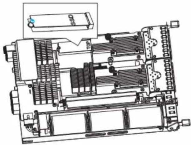
natural_image
Technical line drawing of an internal electronic device with cooling fans and heat sinks (no text or symbols)-
Loosen the screw at the end of flash backup module. Lift it up at a 45 degree angle and remove it than from the base board.
-
Insert the replacement flash backup module on a 45 degree angle, gently lower the other end of the SSD and secure it with the original screw.
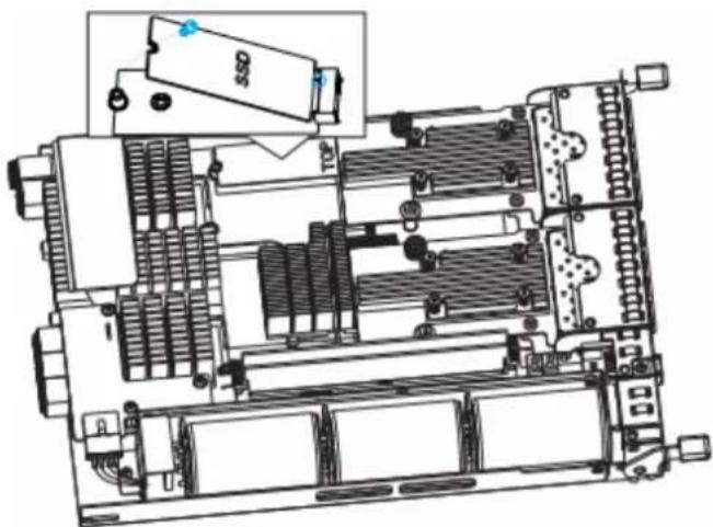
natural_image
Technical diagram of an electronic device chassis with internal components and a highlighted component (no text or symbols)- Reinstall the controller
Replacing the Power Supply / Cooling Module
The power supply units (PSU) are configured in a redundant configuration with each PSU housed in a robust steel canister.
Detecting a Failed PSU
If a PSU module fails, the system notifies you through the following indicators:
• PSU status LED locations (1):
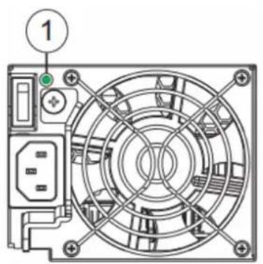
text_image
1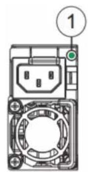
text_image
①• Audible alarm (refer to Audible Alarms)
- Management Software Suite (refer to the respective User Manual in the CD-ROM for details)
Replacing Power Supply Unit
A failed PSU should be replaced as soon as possible, but only when you have a replacement module in your hand. Contact your vendor for more details (refer to Contact Information).

WARNING
Although the system can operate with a failed PSU in a system, it is not recommended to run the system with a failed PSU for an extended period of time. The failed spare redundant PSU should be replaced as soon as possible!
To replace a PSU, follow these steps:
- Turn the switch to the off position and unplug the power cord.
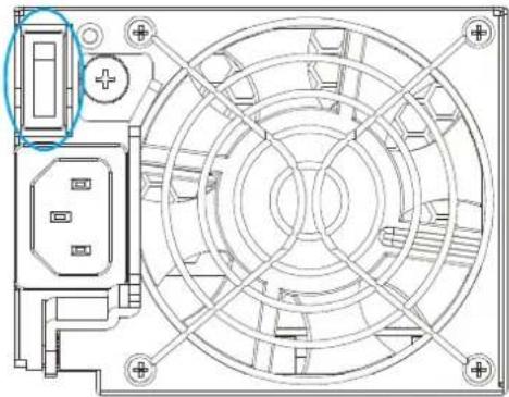
natural_image
Technical line drawing of a circular mechanical component with mounting holes and internal structure (no text or symbols)- Loosen the retention screw that secures the extraction handle to the chassis.
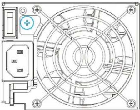
natural_image
Technical line drawing of a circular fan or fan assembly with mounting holes and internal components (no text or symbols)- To remove the PSU module, pull the extraction handle downwards to disconnect the PSU from the backplane connectors. Once dislodged, gently pull the PSU out of the system. If the system is mounted in a rackmount rack, use another hand to support its weight while removing the module.
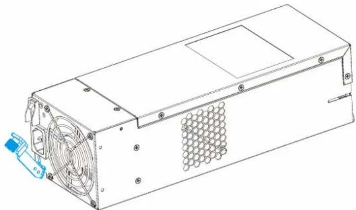
natural_image
Technical line drawing of a power supply unit with fan and socket (no text or symbols)- Insert the replacement module. Make sure the extraction handle is pointing outwards. Push the replacement PSU into the chassis, and when you feel the contact resistance, push the extraction handle towards the PSU module and it should engage the back-end connectors.
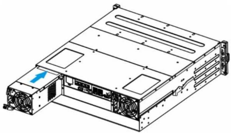
natural_image
Technical line drawing of a server rack with ventilation fans and drive bays (no text or symbols)- Fasten the thumb screw.
- Reconnect the power cord.
- Power on the PSU module.

NOTE:
Should a cooling fan fail within a PSU, the whole PSU module will need to be replaced!
Replacing a Hard Drive

WARNING
Keep a replacement on hand before replacing the hard drive. Do not leave the drive tray open for an extended period of time or the internal airflow will be disrupted.
Handle the hard drives with extreme care. Carry them only by the edges and avoid touching their circuits part and interface connectors.
To replace a hard drive, follow these steps.
-
Identify the drive tray. Use the firmware utility, SANWatch, or the LED on the drive tray to identify faulty hard drive(s). The drive bays are numbered from left to right and from top to bottom.
-
Unlock the drive tray bezel (indicated by the blue arrow) by using a small flat-blade screwdriver to set the bezel lock from lock to the un-lock position.

flowchart
graph TD
    A["Lock"] --> B["Unlock"]
    B --> C["Arrow with Arrow"]
    style A fill:#fff,stroke:#000
    style B fill:#fff,stroke:#000
    style C stroke-dasharray: 5 5
- Open the drive tray. Press the button. The spring handle will pop out.
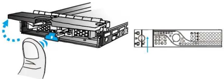
natural_image
Illustration of a hand operating a device with a close-up of its control panel (no text or symbols visible)-
Remove the drive tray. Pull the tray one inch away from the enclosure. Wait for at least 30 seconds for the disk drive to spin down, and then gently withdraw the drive tray from the chassis.
-
Remove four retention screws (two on each side). The screws secure the hard drive to the drive tray.
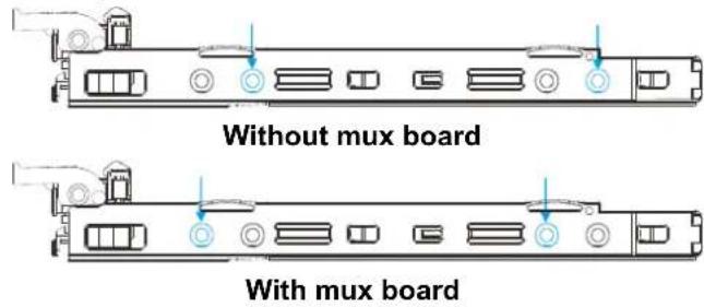
text_image
Without mux board With mux board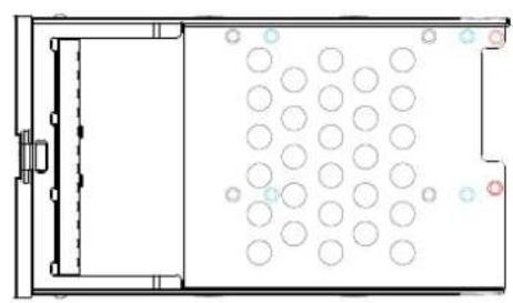
natural_image
Top-down schematic of a room layout with circular elements and a door (no text or symbols)5.5 inch tray
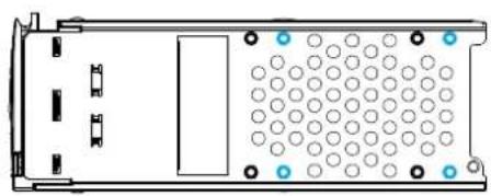
natural_image
Top-down schematic of a device casing with circular components and mounting brackets (no text or symbols)2.5 inch tray
2.5" SAS HDD (without MUX)
2.5" SATA HDD (with MUX)
MUX board screw locations
2.5 inch SAS hard drive
- 2.5 inch SATA hard drive
- Replace the drive. After swapping the drive, fasten the retention screws back. Refer to screw locations in the previous step.
- Insert the drive tray back into the enclosure. Install the drive tray with the front bezel open. When fully inserted, close the front bezel.
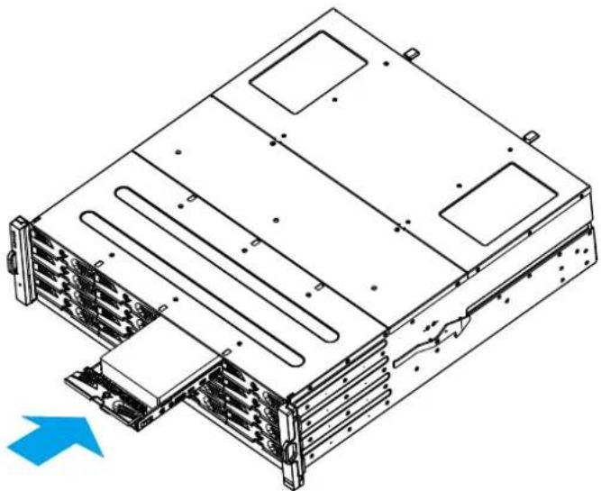
natural_image
Technical line drawing of a server rack with mounting holes and ventilation slots (no text or symbols)
natural_image
Technical line drawing of a mechanical or electronic component with no visible text, numbers, or symbols.- Lock the drive tray. Turn the bezel lock to the vertical orientation (locked position) using a flat blade screwdriver. Do not push the bezel lock while turning it, otherwise the spring handle will pop out again.
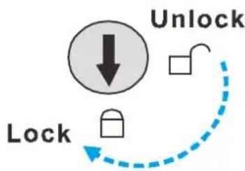
flowchart
graph TD
    A["Lock"] --> B["Unlock"]
    B --> C["Lock"]
    style A fill:#fff,stroke:#000
    style B fill:#fff,stroke:#000
    style C fill:#fff,stroke:#000

NOTE
Never leave the bezel lock unlocked – the RAID controller might consider it as a faulty drive.
- Check for drive error. Make sure that there is no more error reported.

NOTE
The picture showing the installation of the hard drive might show a different design of the HDD tray than the HDD tray you currently use. The general procedure to install the tray is the same.
Appendix
Technical Specifications
Host Board Interface
| Fibre/iSCSI hybrid-host Storage System Systems | |
| Host Interface | 8Gbps / 16Gbps Fibre |
| Drive Interface / channel | Supports 12 / 16 / 24 channels of 3 / 6 / 12 Gbps SAS, SATA-II/SATA-III,Near-line SAS series |
| Host Interface | 8Gbps / 16Gbps Fibre + 2iSCSI (onboard) |
| SAS/iSCSI hybrid-host Storage System Systems | |
| Host O/S Compatibility | Host O/S independent |
| Host Interface | 3Gbps / 6Gbps / 12Gbps Multi-lane SAS |
| Host Channels | Multiple SAS PHYs logically combined into 2 host channels per controller |
| Drive Interface / channel | Supports 12 / 16 / 24 channels of 3 / 6 / 12 Gbps SAS, SATA-II/SATA-III,Near-line SAS series |
| iSCSI-host Storage System Systems | |
| Host O/S Compatibility | Host O/S independent / iSCSI offload utilities and hardware |
| Host Interface | RJ-45 Gigabit Ethernet / RJ-45 10Gb Ethernet / 10Gb FCOE |
| Drive Interface / channel | Supports 12 / 16 / 24 channels of 3 / 6 / 12 Gbps SAS, SATA-II/SATA-III,Near-line SAS series |
| JBOD models | |
| SAS Interface | Eight SMP PHYs interfaced through two / three 12Gb SAS ports |
| Drive Interface / channel | Supports up to 12 / 16 / 24 / 60 channels of 3 / 6 / 12 Gbps SAS,SATA-II/SATA-III, Near-line series |
*Host board interface and specifications are subject to change without prior notice. For the latest specifications and information, please refer to the official EonStor DS website.
Power Supply
| Input Voltage | Dual-Controller model:100VAC @ 10A240VAC @ 5A with PFC (auto-switching) |
| Single-Controller model:100VAC @ 10A240VAC @ 5A with PFC (auto-switching) | |
| Frequency | 50 to 60Hz |
| Power rating | 460W |
| DC Output | 12.0V: 38A (Max.)5.0VSB: 2A (Max.) |
| Input Frequency | 50 to 60Hz |
| AC Input | 100VAC @ 10A or 240VAC @ 5A with PFC |
| Power Factor Correction | Yes |
| Hold-up Time | At least 12ms at 115/230VAC full load after a loss of AC input |
| Over-temperatureProtection | Auto shutdown when lost cooling or exceeded ambient temperature;over-voltage protection is also available. |
*PSU specifications described above are general measurements and do not represent all models. For details, please refer to specific model specifications.
Dimensions
2U series
| Dimensions | Without chassis ears & protrusions |
| Height | 88mm |
| Width | 446mm |
| Length | 514mm |
3U series
| Dimensions | Without chassis ears & protrusions |
| Height | 130mm |
| Width | 445mm |
| Length | 514.04mm |
4U series
| Dimensions | Without chassis ears & protrusions |
| Height | 174mm |
| Width | 445mm |
| Length | 514mm |
Environment
| Humidity | 5 to 95% (non condensing – operating and non-operating) |
| Temperature | Operating:a. With Cache Backup Module 0° to 35°Cb. Without Cache Backup Module 0° to 40°CNon-operating: -40° to 60°C |
| Altitude | Operating: Sea level to 12,000ftPackaged: Sea level to 40,000ft |
| Shock (Half-sine) | Operating: 5G, half-sine, 11ms pulse widthNon-operating: 15G, half-sine, 11ms pulse width |
| Vibration | (Random)Operating: 5 to 500Hz, 0.25Grms, X/Y/Z, 30minNon-operating: 5 to 500Hz, 1.0Grms, X/Y/Z, 30min(Sine)Operating: 5 to 500Hz, 0.2Grms, X/Y/Z Sine, 1hr/sweepNon-operating: 5 to 500Hz, 1.0Grms, X/Y/Z Sine, 1hr/sweep |
| Acoustic Noise | 65dBA boundary, 60dBA normal |
Certifications
Summary
| Safety | UL (60950-1 2'nd)BSMI CNS 14336: 2005CB IEC 60950-1, 2'nd EditionGOST-R GOST R 60950-1-2005 |
| EMC | CE EN 55022: 2006/A1:2007 / EN 61000-3-2: 2006 / EN61000-3-3: 1995/A1: 2001 /A2: 2005 / EN 55024: 1998/A1:2001/A2: 2003IEC 61000-4-2:1995/A2:2000IEC 61000-4-3:1995/A2:2006IEC 61000-4-4:2004IEC 61000-4-5:2005IEC 61000-4-6:2003/A1:2004/A2:2006IEC 61000-4-8:1993/A1:2000,IEC 61000-4-11: 2004IEC 61000-3-2, IEC61000-3-3BSMI (CNS 13438)FCC (FCC Part 15,subpart B ) |
| Environment | IEC 60068-2MIL-STD-810E/883EISTAASTM-D3332IPC-TM-650 |
| Others | ISO7779/3744RoHSMicrosoft WHQL-Windows Server 2003 |
警告使用者:
The table is categorized into model numbers in alphabetical / numeric order so users can fast locate the corresponding slide rail kit for their respective enclosure.
Slide Rail Kits
If you are unable to locate clear instructions on installing your enclosure, please contact Technical Support!
Enclosure Installation Prerequisites
To ensure proper installation and functionality of the Storage System system, please observe the following warnings:
- Cross check all components have been received against the "Unpacking List". Contact your vendor immediately if anything is missing
- Install the enclosure as-is out of the packaging; install hard drives and optional modules (FBM / super capacitor) after the enclosure has been mounted
- Wear an anti-static wristband before and during the installation procedure
- It is recommended to plug the system into two different power sources (e.g. into a power outlet and another into a UPS)
- Ensure the rack which the enclosure will be mounted onto has proper grounding and over-current protection
- Do not obstruct ventilation openings; provide 20cm of free space at the front and back of the enclosure for air circulation; keep the ambient temperature below 35 degrees Celsius
Unpacking the System
Use the "Unpacking List" to cross check all components have been received. The basic contents include one GUI CD pack, Quick Installation Guide and Storage System System Installation Guide. For details on each slide rail kit contents, please refer to specific kit installation details in this manual.
Component Installation Procedure
Please install components in the following order:
- Rackmount rails onto the enclosure / rack / cabinet
- Enclosure onto the slide rail and into the cabinet
- Hard drives into drive trays and then into the enclosure.
- Drive trays (with or without hard drives) into the enclosure
- If super capacitor / FBM were purchased as an optional component, the controller must be removed from the enclosure for installation.

NOTE
For detail procedures from step 3 and onwards, please refer to the earlier sections in this hardware manual.
Tools Required
For each of the slide rail installation procedures, you will need the following tools:
• One medium sized Phillips screwdriver
• One small sized Phillips screwdriver
• One medium size flat blade screwdriver
Rackmount Slide Rail Kits
Rack Ear Mount Kit
The following table shows all accessories that came with the rack ear mount kit.
Kit Contents
| Item | Description | Quantity |
| 01 | Mounting bracket assembly, left-side | 1 |
| 02 | Mounting bracket assembly, right-side | 1 |
| 03 | Hexagon washer screws #6-32mm | 8 |
| 04 | Truss head screws M5 x 9.0mm | 4 |
| 05 | M5 cage nuts | 4 |
| 06 | M5 x 25mm | 4 |
| 07 | M6 x 25mm | 4 |
| 08 | #10-32 x 25.4mm | 4 |
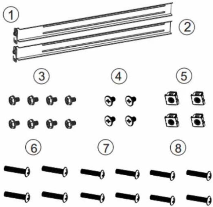
text_image
Diagram showing eight numbered arrangements of mechanical components, including rod, nut, and camera with corresponding pin arrangements.Installation Procedure
- The installation begins with determining the installation position and M5 cage nut (5) insertion location.
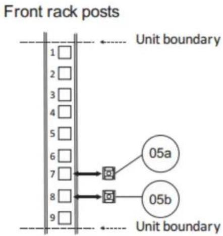
text_image
Front rack posts Unit boundary 1 □ 2 □ 3 □ 4 □ 5 □ 6 □ 7 □ 8 □ 9 □ 05a 05b Unit boundary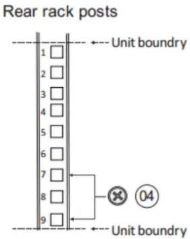
text_image
Rear rack posts Unit boundary 1 □ 2 □ 3 □ 4 □ 5 □ 6 □ 7 □ 8 □ 9 □ Unit boundary × 04 Unit boundary| Item | Description |
| 04 | Screws M5 x 9.0 mm |
| 05a | Cage nuts M5, 3U / 4U position |
| 05b | Cage nuts M5, 2U position |
- Install the fixed rack ear mount to the rear posts and secure them using truss head screws (4)
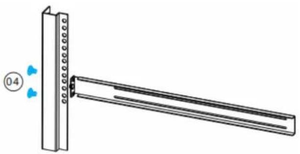
natural_image
Diagram of a mechanical assembly with a vertical plate and a long rod, showing no text or symbols.| Item | Description |
| 04 | Screws M5 x 9.0 mm |
- With the assistance of another person holding the enclosure at the installation height, the other person can place two M5 or M6 x 25mm (6) at the front of the enclosure and eight #6-32 screws (3), four on each side, to secure the enclosure into the rack.
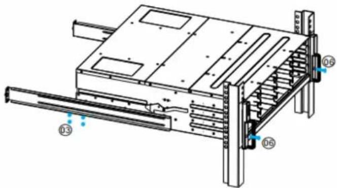
text_image
Technical diagram of a server rack with labeled components including 03, 06, and 05| Item | Description |
| 03 | Screws #6-32L4 |
| 06 | Screws M5 x 25 mm or |
| 07 | Screws M6 x 25 mm or |
| 08 | Screws #10-32 x 25.4mm |
Slide Rail Kit
The following table shows all accessories that came with the slide rail kit.
Kit Contents
| Item | Description | Quantity |
| 01 | Mounting bracket assembly, left-side | 1 |
| 02 | Mounting bracket assembly, right-side | 1 |
| 03 | Inner glides | 2 |
| 04 | Flathead screws #6-32 L4 | 6 |
| 05 | Truss head screws M5 x9.0mm | 8 |
| 06 | M5 cage nuts | 4 |
| 07 | M5 x 25mm | 4 |
| 08 | M6 x 25mm | 4 |
| 09 | #10-32 x 25.4mm | 4 |
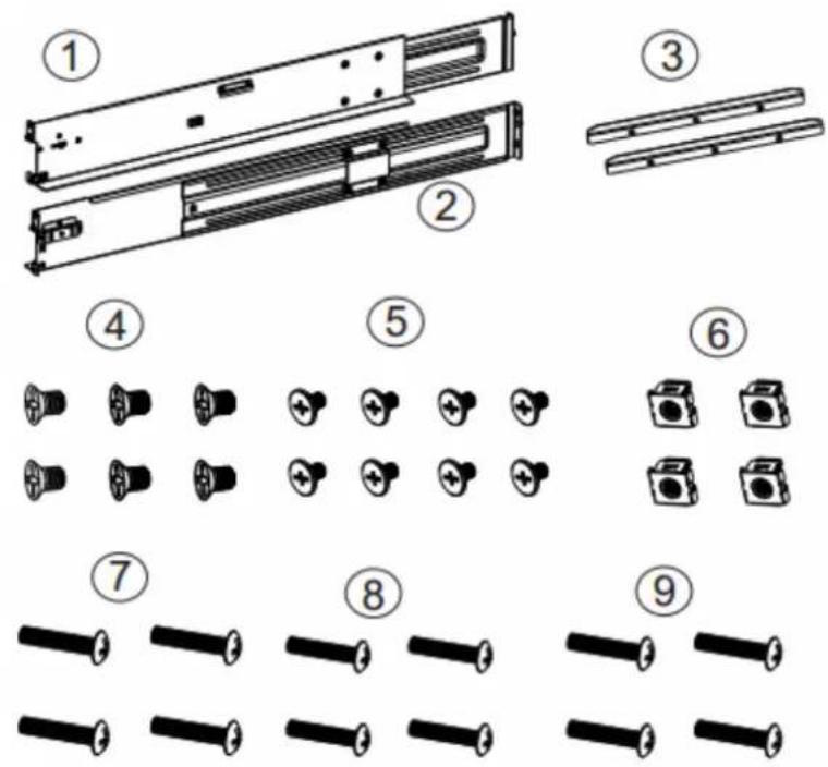
Installation Procedure
- The installation begins with determining the installation position (front and rear rack positions) and M5 cage nut (5) insertion location.
Front rack posts
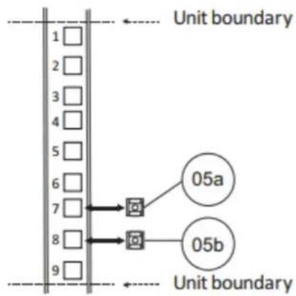
flowchart
graph TD
    A["1"] --> B["05a"]
    C["2"] --> D["05a"]
    E["3"] --> F["05a"]
    G["4"] --> H["05a"]
    I["5"] --> J["05a"]
    K["6"] --> L["05a"]
    M["7"] --> N["05a"]
    O["8"] --> P["05a"]
    Q["9"] --> R["05a"]
    S["05b"] --> T["05a"]
    U["05b"] --> V["05a"]
Rear rack posts
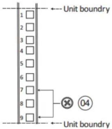
text_image
Unit boundary 1 2 3 4 5 6 7 8 9 Unit boundary| Item | Description |
| 04 | Screws M5 x 9.0 mm |
| 05a | Cage nuts M5, 3U / 4U position |
| 05b | Cage nuts M5, 2U position |
- Adjust the length by loosening the four screws on the slide rail. Secure the slide rails to front and rear posts using truss head screws. Tighten the four screws on the slide to fix the length.
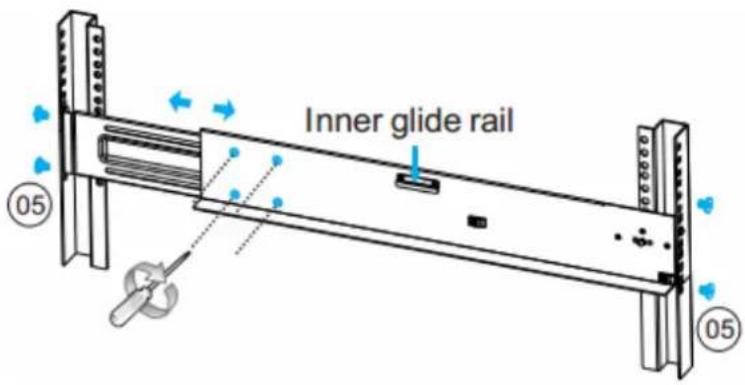
text_image
Inner glide rail 05 05| Item | Description |
| 05 | Truss head screws M5 x 9.0mm |
- Attach the inner glides to BOTH sides of the enclosure using flathead screws #6-32 (8)
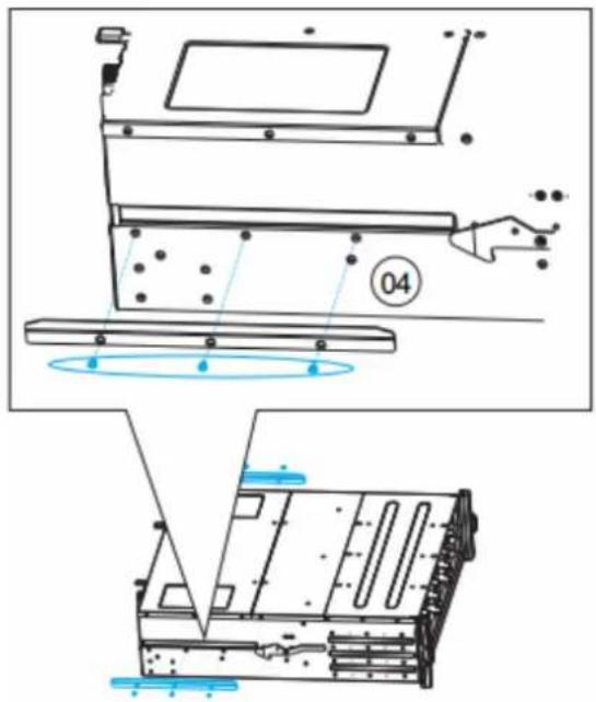
text_image
Technical diagram showing assembly steps of a device with labeled components and motion indicators| Item | Description |
| 04 | Flathead screws #6-32 L4 |
- With the assistance of another person, lift and insert the enclosure onto the slide
rail. Make sure the inner glides on both sides of the enclosure meets the inner glide rail. Secure the enclosure with M5 or M6 screws from the front.
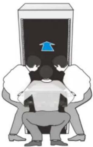
natural_image
Illustration of three people sitting under a computer monitor with an upward arrow, no text or symbols present-
To insert the enclosure into the rack, with at least three people lifting the enclosure, align the end of the enclosure slide rail to the opening of the rack slide rail and gently insert it into the rack. You should hear a "click" sound when the enclosure slide rail engages the rack slide rail at the release lever.
-
Secure the system using two 20mm screws and cage nuts from the accessory box.
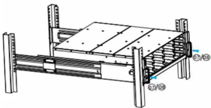
natural_image
Technical line drawing of a mechanical assembly with labeled components (no text or symbols beyond part numbers)| Item | Description |
| 07 | Screws M5 x 25 mm or |
| 08 | Screws M6 x 25 mm or |
| 09 | Screws #10-32 x 25.4mm |
Once Mounted
Once the enclosure has been mounted, you may refer to the User's Manual that came with your system for further instructions on completing the hardware installation process. The User's Manual will go on to explain details on installation / maintenance of hard drives, controllers, optional modules (super capacitor, CBM, etc.), cooling modules, power supplies, cable connections, topology configurations, etc.
Safety Reminders
If you must relocate the enclosure after installation
- Cease all input / output transactions, shutdown the system, disconnect all the cables (please refer to the User Manual for details)
- Empty all drive bays (hard drives + hard drive trays) and transport them separately in safe packaging
- Modules came installed within the enclosure need not be removed
When the system is in operation
- Module and drive bays must not be empty! They must have a dummy cover / plate in place to stabilized internal airflow!
- Should a module fail, leave it in its place until you have the replacement item on-hand to take its place
- Allow at least 18\~20cm of clearance space at the rear of the enclosure for ventilation
- Avoid touching the PCB and gold-finger connections.