EonStor GSa 3025 - NAS Infortrend - Free user manual and instructions
Find the device manual for free EonStor GSa 3025 Infortrend in PDF.


User questions about EonStor GSa 3025 Infortrend
0 question about this device. Answer the ones you know or ask your own.
Ask a new question about this device
Download the instructions for your NAS in PDF format for free! Find your manual EonStor GSa 3025 - Infortrend and take your electronic device back in hand. On this page are published all the documents necessary for the use of your device. EonStor GSa 3025 by Infortrend.
USER MANUAL EonStor GSa 3025 Infortrend
EonStor GSa 3000 Series Hardware Manual
Version 1.0
September 2018
Legal information
All Infortrend products, including the product customers have purchased from Infortrend, shall be subject to the latest Standard Warranty Policy available on the Infortrend website:
https://www.infortrend.com/global/Support/terms-conditions
Infortrend may from time to time modify, update or upgrade the software, firmware or any accompanying user documentation without any prior notice. Infortrend will provide access to these new software, firmware or documentation releases from certain download sections of our website or through our service partners. Customer shall be responsible for maintaining updated version of the software, firmware or other documentation by downloading or obtaining from Infortrend, and installing designated updated code, including but not limited to firmware, microcode, basic input/out system code, utility programs, device drivers, and diagnostics delivered with Infortrend product.
Before installing any software, applications or components provided by a third party, customer should ensure that they are compatible and inter-operable with Infortrend product by checking in advance with Infortrend. Customer is solely responsible for ensuring the compatibility and interoperability of the third party's products with Infortrend product. Customer is further solely responsible for ensuring its systems, software, and data are adequately backed up as a precaution against possible failures, alternation, or loss.
For any questions of hardware/ software compatibility, and the update/ upgrade code, customer should contact Infortrend sales representative or technical support for assistance.
To the extent permitted by applicable laws, Infortrend shall NOT be responsible for any interoperability or compatibility issues that may arise when (1) products, software, or options not certified and supported by Infortrend are used; (2) configurations not certified and supported by Infortrend are used; (3) parts intended for one system are installed in another system of different make or model.
Copyright notice
All rights reserved. This publication may not be reproduced, transmitted, transcribed, stored in a retrieval system, or translated into any language or computer language, in any form or by any means, electronic, mechanical, magnetic, optical, chemical, manual or otherwise, without the prior written consent of Infortrend Technology, Inc.
Disclaimer
Infortrend Technology makes no representations or warranties with respect to the contents hereof and specifically disclaim any implied warranties of merchantability or fitness for any particular purpose. Furthermore, Infortrend Technology reserves the right to revise this publication and to make changes from time to time in the content hereof without obligation to notify any person of such revisions or changes. Product specifications are also subject to change without prior notice.
Trademark
Infortrend, the Infortrend logo, EonOne, ESVA, EonStor, EonStorGSa, EonNAS, and EonPath are registered trademarks of Infortrend Technology, Inc. Other names prefixed with "IFT" and "ES" are trademarks of Infortrend Technology, Inc.
- Windows is a registered trademark of Microsoft Corporation.
• Mac OS X is a registered trademark of Apple Computer, Inc.
• Linux is a trademark of Linus Torvalds.
All other names, brands, products or services are trademarks or registered trademarks of their respective owners.
Table of Contents
Safety precaution....v
About this manual....vi
Revision history......vii
Hardware specifications......viii
Package contents....xii
System package....xii
Power cord, cable, and accessory boxes....xii
Pre-installed components ......xiii
Rackmount kit contents ......xiii
Chapter 1: Product Introduction
1.1 Overview....1-1
1.1.1 Major components....1-1
1.2 Chassis....1-2
1.2.1 Front panel 1-2
1.2.2 Rear panel....1-3
1.2.3 Internal backplane....1-3
1.3 Front panel components....1-4
1.3.1 LED and buttons panel....1-4
1.4 Rear panel components....1-6
1.4.1 Controller module interface 1-6
1.4.2 Controller module interfaces of the JBOD models 1-7
1.4.3 PSU/cooling module....1-8
1.4.4 Super capacitor and flash backup module 1-9
1.5 System monitoring features 1-10
1.5.1 Expansion enclosure support....1-10
1.5.2 Audible alarms 1-11
1.6 Hot-swappable components....1-11
Chapter 2: Hardware installation
2.1 Installation prerequisites....2-1
2.2 Installation procedures 2-2
2.2.1 Unpacking the system....2-2
2.2.2 Installing the rackmount kit....2-2
2.2.3 Installing the hard drives 2-7
2.2.4 Installing the host boards 2-11
2.3 Connections....2-13
2.3.1 General considerations in connecting devices....2-13
2.3.2 Fibre-Host connections 2-15
2.3.3 SAS - host connections....2-22
2.3.4 Ethernet - host connections 2-26
2.3.5 Hybrid host connections....2-32
2.3.6 Expansion connections 2-34
2.3.7 Management console connections....2-41
2.3.8 Power connection....2-42
2.3.9 Turning off the system....2-44
Chapter 3: System monitoring
3.1 Monitoring features 3-1
3.1.1 LEDs 3-2
3.1.2 Alarms and I ^2 C bus 3-9
Chapter 4: System maintenance
4.1 Replaceable components 4-1
4.1.1 Replacing the PSU/cooling module....4-2
4.1.2 Replacing the controller module....4-3
4.1.3 Replacing the memory module 4-6
4.1.4 Replacing the CBM (Cache Backup Module) components....4-7
4.1.5 Replacing the host board 4-11
4.1.6 Replacing the hard drive 4-13
Appendices
Technical specification....A-1
Host board interface ...... A-1
Certifications A-2
User warning A-2
Declaration of the presence condition of the restricted substance marking....A-3
Contact information....A-4
Safety precaution
Read these instructions carefully before you install, operate, or transport the Infortrend storage systems and expansion systems.
Energy hazards precaution
This equipment is intended to be used in a restricted access location, like a computer room. Only allow access to SERVICE PERSONS or users who have been instructed about the metal chassis of the equipment, which may have hazardous energy that service persons must pay attention or take special protection before touching it. Also, the access is through the use of a key or security identity system. Only the authorized and well-trained personnel can access the restricted access location.
Installation and operation
• Install the rack cabinet and the associated equipment at a site where the ambient temperature (special room cooling equipment may be required) stays lower than 40^ C.
• Install the power source socket outlet near the enclosure where it is easily accessible and ground the rack cabinet.
- Secure airflow clearance inside and around the rack cabinet.
- Secure an 18 to 20~cm clearance on the rear side.
- Do not cover the enclosure openings.
- Route the cables inside the rack cabinet.
- Do not leave drive bays empty as it will affect airflow efficiency.
- Secure each enclosure module using its retention screws.
- Place power cords and other cables away from foot traffic. Do not place items on top of power cords and ensure they do not rest against data cables.
• Install all modules to the enclosure before turning on the systems.
- Ensure that the correct power range is tested before turning on.
- DO NOT remove the covers or replaceable modules if they are not faulty.
- If the system is used for a long period of time, disconnect it from the power outlet to avoid transient over-voltage.
- For power source redundancy, ensure that the two PSUs are plugged into two different power sources (i.e. different circuit breakers).
Service and maintenance
- Keep the faulty module in place until you have a replacement unit; an empty module greatly affects the airflow efficiency within the enclosure.
- During service operation, place the enclosure on a soft and clean surface to prevent exterior damage. Do not place tools or other items on top.
- When transporting the enclosure, repackage all disk drives separately in the original package foam blocks. Replaceable modules can stay in the enclosure if you are using the original package; if not, repackage them separately as well.
- Disconnect the power cords before servicing or cleaning the enclosure.
• Use a slightly moistened paper sheet or cloth for cleaning. Avoid using liquid or sprayed detergent.
- When replacing components, insert them as gently as possible while assuring full engagement. Vibration and shock can easily damage hard drives.
- Only qualified service personnel should open the enclosure.
- Contact service personnel if any of the following situations occurs:
• The power cord or plug is damaged.
- The enclosure has been exposed to moisture.
- The system has not been working properly.
- The enclosure was dropped against a hard surface.
- The enclosure shows obvious signs of breakage.
• To move the enclosure, more than one person might be necessary due to its weight. Drives should be removed from the enclosure beforehand.
Important notice
The use of Infortrend certified components is strongly recommended to ensure compatibility, quality, and normal operation with your Infortrend products. Contact your distributor for a list of Infortrend certified components (e.g. SFP, SFP+, HBA card, iSCSI cable, FC cable, memory module, etc.).
ESD precautions
- Handle the modules by their retention screws, ejector levers, or the module's metal frame/faceplate only. Avoid touching the PCB boards or connector pins.
- Use a grounded wrist strap and an anti-static work pad to discharge static electricity when installing or operating the enclosure.
- Avoid dust, debris, carpets, plastic, vinyl, and Styrofoam in your work area.
- Do not remove any module or component from its anti-static bag before installation takes place.
- Drives must not be stacked on top of each other without their protective drive trays. Even when drives are fixed in the drive trays, contacting the exposed PCB or rear-side interface may damage the drives.
About this manual
The manual introduces hardware components of EonStor GSa 3000 storage system and expansion enclosures. It also describes how to install, monitor, and maintain them.
- For non-serviceable components, contact our support sites.
- Firmware operation: Consult the Firmware User Manual on the CD-ROM.
- EonOne software: Consult the EonOne User Manual on the CD-ROM.
Revision history
Version Date Description
1.0 September 2018 Initial release
Hardware specifications
Specification summary
| Form factor 2U 25-bay EonStor GSa 3025 | |
| Controller Dual redundant controllers | |
| Cache memory - 16 GB DDR4 (2 x 8 GB) | - 32 GB DDR4 (2 x 16 GB)- 64 GB DDR4 (4 x 16 GB)- 128 GB DDR4 (4 x 32 GB)- 256 GB DDR4 (8 x 32 GB)Note: The installed default memory varies by model, region, and other factors. Contact your local sales representative for details. |
| Host ports Onboard Gb/s ports: | - 4 x 1 Gb/s iSCSI ports (2 per controller)- 4 x 10 Gb/s iSCSI ports (2 per controller)More host options:- 8 x 10 Gb/s iSCSI/RJ-45 ports (4 per controller)- 8 x 12 Gb/s SAS ports (4 per controller)- 8 x 16 Gb/s Fibre Channel ports (4 per controller)*- 8 x 40 Gb/s iSCSI/QSFP ports (4 per controller)- 8 x 56 Gb/s InfiniBand ports (4 per controller) - for Linux only, block level only- 16 x 1 Gb/s iSCSI ports (8 per controller)- 16 x 8 Gb/s Fibre Channel ports (8 per controller)*- 16 x 10 Gb/s FCoE ports (8 per controller)- 8 or 16 x 10Gb/s iSCSI ports/ SFP+ (4 or 8 per controller)*Supports point-to-point and switch mode |
| Cache backup technique Super capacitor + Flash module | |
| Drive connectivity 12 Gb/s SAS connectivity | |
| Maximum number of drives System: 25 | Expansion: 400 and 775 (with expansion board) |
| Disk support 2.5-inch SATA SSD | 2.5-inch SAS SSDNOTE: Refer to the Compatibility Matrix for the latest compatibility details. |
| Supported protocols File level protocol | - CIFS/SMB- AFP- NFS- FTP- FXP-WebDAVBlock level protocol- FC- FCoE- iSCSI- InfiniBand- SAS |
(See next page)
Specification summary
| Supported protocols Object protocol | - RESTful API |
| Cloud gateway - Amazon S3 | - Microsoft Azure- Alibaba AliCloud- OpenStack |
| RAID functionality Global, dedicated, or enclosure hot spare | RAID level supported: 0, 1 (0 + 1), 3, 5, 6, 10, 30 60Online expansion:- Adding new drives- Copying and replacing drives of larger capacityRAID migration:- Configurable stripe size and write policy per system- Intelligent drive handlingIn degraded mode: skips irreparable blocks to continue rebuildIn normal operation: data-block verification and repair |
| Data protection and service Thin provisioning | Remote replication*: Synchronous or asynchronous for both block level and file levelLocation replication**: Snapshot, volume copy/mirror* Optional** Available with Standard license and optional Advanced license |
| Green design 80 PLUS-certified power supplies delivering more than 80% energy efficiencyIntelligent multi-level drive spin-down | |
| Availability and reliability - Redundant, hot-swappable hardware modules- CacheSafe technology- Multipathing support (EonPath)- Device mapper support | |
| Notification Various event notification methods including email and SNMP trap. | |
| Management - Web-based EonOne management software | - Automated cache flush and caching mode operation per enclosure status- Module status LED indicators: component presence detection and thermal sensors via I2C bus- Storage Resource Management to analyze history records of resource usage- Automated repeatable management tasks by flexible workflow |
| Network configuration - IPv6 support | - Fixed or dynamic address- Dual Gigabit Ethernet with Jumbo Frame- Port trunking, NIC teaming, Link aggregation (IEEE 802.3ad)- DHCP client- MPIO, MC/S support |
(See next page)
Specification summary
| Access right management User account management | Group managementFolder management- Folder and sub-folder access controlFolder quotaComprehensive access control action items- All controls, Read, Read and Run, Modify, ListSupport Windows Active Directory Authentication- Domain Users Login via CIFS/SMB, AFP, FTP, and file explorerLDAP on Linux |
| OS support - Windows | ^® Server 2008/R2- Windows ^® Server 2012/R2- Windows ^® Server 2016*- Red Hat ^® Enterprise Linux ^® - SUSE ^® Linux ^® Enterprise- Sun ^® Solaris ^TM - MacOS ^® X- HP-UX- IBM ^® AIX ^® - VMware ^®** - Citrix ^® XenServer ^® * Includes Hyper-V** NFS protocol running on VMware environment is not supported currentlyNote: Contact your local sales representative for the latest OS support details. |
| Service and support Standard services: | - 3-year limited hardware/software warranty- 8 x 5 phone, web, and email supportUpgraded/extended services:- Replacement of part dispatch on the next business day (up to 5 years)- Advanced service of 24/7 phone, web, email support, and on site diagnostics on the next business day- Premium service of 24/7 phone, web, email support, and on site diagnostics in 4 hoursNote: The upgraded/extended services are optional and vary by region. |
| Power - Power supply: 2 x Redundant/hot-swappable 530 W | - AC voltage: 100 VAC (10A) - 240 VAC (5A) with PFC (auto-switching)- Frequency: 47 - 63 Hz |
| Environment Temperature: | - Operating: 0°C - 40°C without BBU/CBM, 0°C - 35°C with BBU/CBM- Non-operating: -40°C - 60°CAltitude:- Sea level to 3048 m (10,000 ft.) operating/sea level to 12,192 m (40,000 ft.) non-operating- Relative humidity: 5% - 95% non-condensing, operating and non-operating |
(see next page)
Specification summary
| Regulations Safety: UL, BSMI, CB | Electromagnetic compatibility: CE, BSMI, FCC |
| Dimension 449 mm x 88 mm x 500 mm | Notes:• The dimensions do not include chassis ears/protrusions.• The dimension order is W x H x D. |
| Weight 17397 kg/39.62 lbs. (with SSDs) | |
| Package dimension 588 mm x 340 mm x 780 mmNote: The dimension order is W x H x D. | |
NOTE: For the expansion enclosures, refer to the data sheet or download it from our official website.
Package contents
Check the unpacking list for the complete list of contents and exact quantity of the components of your system.
NOTE: The contents and quantity may vary depending on the system model and order requests.
System package
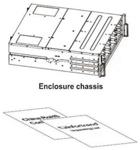
Unpacking list and China RoHS compliance documentation
natural_image
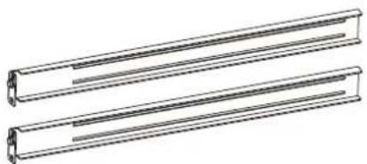
Technical line drawing of two parallel cylindrical metal profiles (no text or symbols)Rackmount kit
text_image
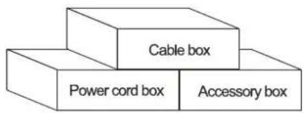
Cable box Power cord box Accessory boxPower cord, cable, and accessory boxes
Power cord, cable, and accessory boxes
natural_image
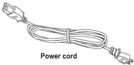
Line drawing of a power cord with two connectors (no text or symbols on the cord itself)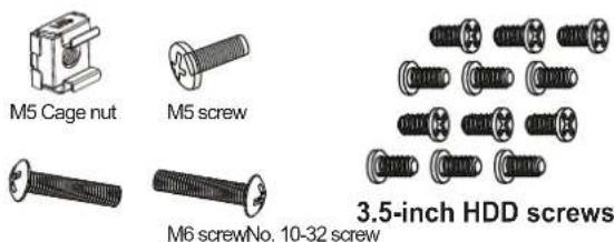
2.5-inch HDD screws
Quick configuration guide
natural_image
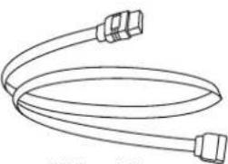
Simple line drawing of two coiled cable or hose connectors (no text or symbols)SAS cable
Software CD
Quick installation guide
Pre-installed components
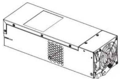
natural_image
Technical line drawing of a computer power supply unit with fan and ventilation slots (no text or symbols)PSU/Cooling module
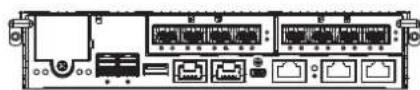
Controller module
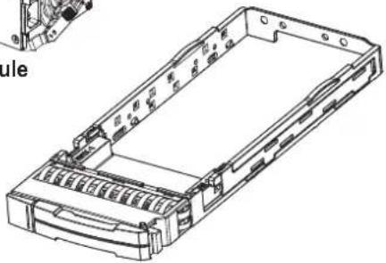
natural_image
Technical line drawing of a mechanical housing or enclosure with internal components and mounting holes (no text or symbols)Drive tray
Rackmount kit contents
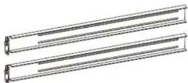
natural_image
Two identical 3D schematic lines of parallel rectangular components, no text or symbols present.2 x Rack ear brackets (left and right)
- OR -
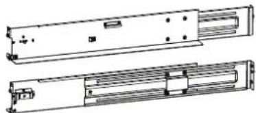
natural_image
Technical line drawing of two mechanical components with mounting holes and internal ribs (no text or symbols)2 x Slide rails (left and right)
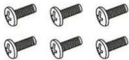
6 x 6 mm M4 screws
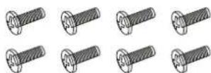
8 x 10 mm M5 screws
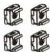
4 x Cage nuts
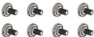
8 x Screws
NOTE: See section 2.2.2 Installing the rackmount kit for the types of mounting kit and the exact package contents.
Product introduction
1
This chapter introduces the look and feel of EonStor GSa 3000 Series systems, the features, and the supported components.
1.1 Overview
This manual introduces EonStor GSa 3000 systems that support SAS, Near-line SAS, and SATA SSDs. This system is designed to utilize 2.5-inch SSDs. Drive capacity can be expanded by attaching expansion hard drive enclosures.

natural_image
Technical line drawing of a multi-panel industrial or storage unit structure with vertical supports and horizontal bars (no text or symbols)EonStor GSa 3025
1.1.1 Major components
NOTE: Upon receiving the system, check the package contents and compare them to the Unpacking List. If one or more of the modules are missing, contact your system vendor.
Controller and interface
The system has controllers, and each controller comes with pre-installed DIMM modules. It also has a CBM (cache backup module), a module that has a super capacitor and an FBM (flash backup module). With the CBM, the cached data is quickly distributed to the FBM to save the data permanently with the support of the super capacitor if power outage occurs. With the super capacitor's fast-charging feature, it can distribute a fair supply of power to the controller, so the controller can save cache data to the FBM immediately and permanently.
Also, the embedded firmware features earth-friendly and smart algorithms that you can use to customize your system's hardware settings such as power-saving modes, variable fan speeds, and exiled drive handling.
Expansion controller and interface
The expansion enclosure is managed by expander controllers that distribute data flow to individual disk drives and report operating status through a proprietary enclosure service via in-band protocols. The enclosure, along with other expansion systems, connects to a SAN system and serves as a building block of a scalable configuration.
For supported protocols, the firmware supports communications with enclosure devices, SAS/SATA disk drives, and SAN system that features SAS expansion ports.
For physical connection, the SAS interface provides easy cabling routes via mini-SAS connectors. With the backplane-adapting SAS or SATA drives, the system can support enterprise-class SAS, Near-line SAS, and cost-effective SATA-II or SATA-III SSDs. This connection is ideal for adding large capacity storages to a storage pool.
Power supply unit/cooling module
There are two PSU/cooling modules in the system. Each PSU/cooling module is hot-swappable and is built with a fan to protect the system from overheating while providing constant power. The modular architecture of the system and easy accessibility to all major components provide you an easy maintenance.
1.2 Chassis
This section describes the front and rear panels of EonStor GSa 3000 Series's rugged storage chassis. The chassis are designed to allow installation to the rack or a cabinet.
1.2.1 Front panel
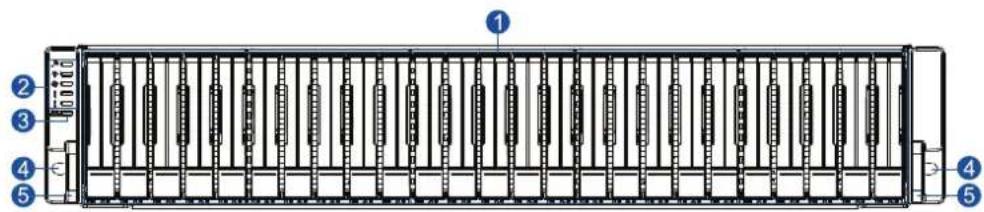
text_image
Technical diagram of a rack-mounted device with numbered components and labeled parts| Number Part Description | ||
| 1 | Drive trays Each drive tray is hot-swappable and holds a 2.5-inch SSD. | |
| 2 | LED panel | LED panel has service, power, cooling fan, thermal, and system LEDs. |
| 3 | Mute button/Service LED | This button mutes the alarm while the embedded Service LED notifies you that the system requires service. |
| 4 | Rackmount holes | These holes secure the enclosure to the rackmount system with the mounting screws. |
| 5 | Handles | These handles allow you to push/pull the enclosure to/from the cabinet installed in the rackmount system. |
1.2.2 Rear panel
Single controller system

text_image
Diagram of a server rack with labeled ports and connectors, showing front and rear views with numbered components.Dual controller systems

text_image
Diagram of a server rack with labeled ports and connectors, showing front and rear views with numbered annotations.| Number Part Description | ||
| 1 | Controller A | This controller module contains the SAS expansion board which distributes I/O functions to and from the managing RAID system. This also handles the status of the components via the SAS links with the RAID system. |
| 2 | Controller B or dummy cage | This part contains the second controller, also called the redundant controller. This controller takes over the system functions when Controller A fails to process.For single-controller system, this contains a dummy cage. |
| 3 | PSU/cooling module | These hot-swappable modules provide power to the storage system and each module has a built-in fan. |
| 4 | Power button This button allows you to turn ON/OFF your storage system. | |
WARNING! DO NOT remove the redundant components without a replacement on hand.
1.2.3 Internal backplane
The internal backplane is a circuit board that separates the front and rear parts of the chassis. This provides logic level signals and low voltage power paths. The thermal sensors and PC devices are embedded to detect system temperatures and PSU/cooling module's operating status. This board is comprised of non-user-serviceable components.
WARNING!
- Accessing the backplane board may lead to serious damage to the system.
• Physical contact with the backplane board may cause electrocution.
1.3 Front panel components
This section describes the front panel components of GSa 3000 systems.
1.3.1 LED and buttons panel
The LEDs on this panel allow you to know your system's current status when turned on, while the button has a specific function that you can set.
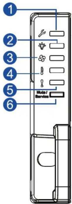
text_image
1 2 3 4 5 6 Auto / Service| Number Part Description | ||
| 1 | Service LED | This LED provides the status when the system requires service or currently in service. |
| 2 | Power LED This LED provides the status of the system's power. | |
| 3 | Cooling fan status LED | This LED provides the cooling fan's status. |
| 4 | Temperature status LED | This LED provides the system's temperature status. |
| 5 | System fault LED | This LED provides the system's operation status. |
| 6 | Mute button/Service LED | This button mutes the alarm while the embedded Service LED notifies you that the system requires service. |
NOTE: For more details regarding the LEDs and their respective status, refer to 3.1.1 LEDs.
WARNING! If critical faults are indicated on the LED panel, verify the cause of the problem as soon as possible and contact your system vendor for a module replacement.
1.3.2 Drive tray bezel
The drive tray bezel is designed to accommodate both SAS and SATA-interfaced SSDs (solid-state drives). Get familiarized of the components of your system's drive tray bezel.
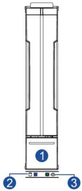
natural_image
Technical line drawing of a vertical cylindrical device with numbered components (1, 2, 3) and no visible text or symbols on the body.| Number Part Description | |
| 1 | Release button Push this button to unlock the drive tray from the drive tray slot. |
| 2 | Drive busy LED This LED provides the status of the SSD. |
| 3 | Power status LED This LED provides the power status of the SSD. |
WARNING! Be careful not to drop or put heavy objects on the drive tray, as these may cause to bend or deform the drive tray's structure. If the drive tray is deformed, it may not fit into the system's drive bay.
1.4 Rear panel components
This section describes the rear panel components of GSa 3000 Series systems.
1.4.1 Controller module interface
The I/O interfaces of the controller module allow you to connect to other devices and the LEDs allow you to know the status of your controller.
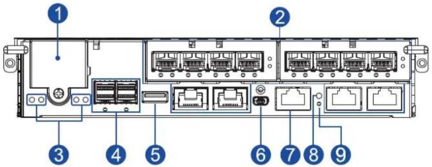
text_image
Diagram of a rack-mounted server with labeled ports and internal componentsNumber Part
| 1 | CBM (Cache Backup Module) |
| 2 | Host ports |
| 3 | Controller status LEDs |
| 4 | SAS expansion ports |
| 5 | USB service port |
| 6 | Mini USB port (console) |
| 7 | Ethernet management port |
| 8 | Restore Default button |
| 9 | Restore Default LED |
WARNING! The controller module is built of sensitive and non-replaceable components. When replacing the controller module, you can only remove it from the enclosure when you already have the replacement. Unnecessary tampering may damage the controller.
IMPORTANT! The host boards are add-on components. When installing a host board for the first time, insert it on the left slot (HB1).
NOTES:
• The Ethernet management port only supports 100 Mb and 1 Gb speeds.
- For more information about super capacitor and flash backup module, see section 1.4.4 Super capacitor and flash backup module.
1.4.2 Controller module interfaces of the JBOD models
The controller module of a JBOD system contains a circuit board within a metal canister, integrated with the hot-swap docking connectors at the backend. Two SAS wide ports on the interface faceplate connect to a managing GSa system or other expansion systems.
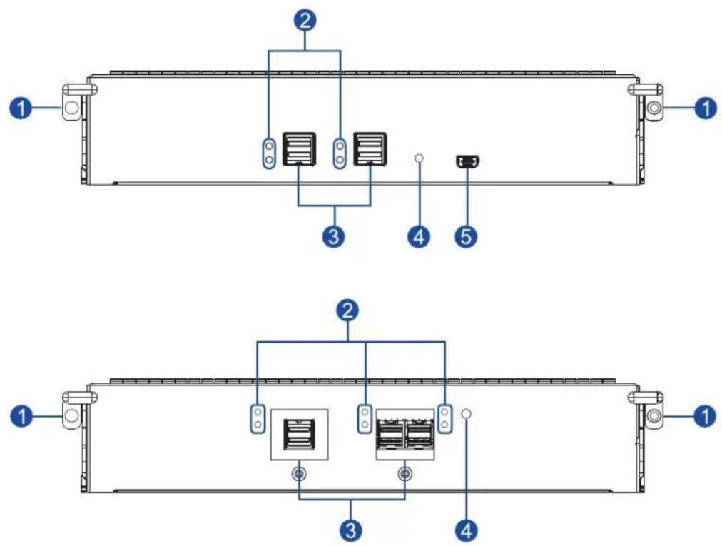
| Number Part | |
| 1 | Extraction levers/screw holes |
| 2 | SAS expansion port status LEDs |
| 3 | SAS expansion ports |
| 4 | Controller status LED |
| 5 | Mini USB service port |
WARNING! You can only remove the controller when you already have the replacement. The GSa controller is built of sensitive components. Unnecessary tampering may damage the controller.
1.4.3 PSU/cooling module
The GSa 3000 Series system has redundant hot-swappable PSU/cooling modules that help with the airflow, providing an efficient ventilation.
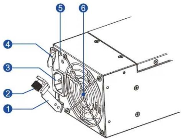
text_image
Technical diagram of a computer drive with numbered components for identification| Number Part | |
| 1 | Extraction lever |
| 2 | Retention screw |
| 3 | Power socket |
| 4 | Power switch |
| 5 | PSU status LED |
| 6 | Fan |
When the cooling modules operate under normal conditions, the cooling fans run at a low speed. The cooling fans raise their rotation speed to increase the airflow under the following conditions:
- Component failure: If the cooling module, PSU, or temperature failed.
- Elevated temperature: If the temperature breaches the upper threshold set for any of the interior temperature sensors.
During the initialization stage, the cooling fans operate at a high speed. The speed is lowered when the initialization is completed and no errors are detected.
NOTES:
- The PSU/cooling modules have specific installation orientations for left and right slots. Refer to the label at the back of the system.
- There are two upper temperature thresholds: one for event notification and the other for triggering high fan rotation speed. You can change the preset values for event notification using the firmware-embedded configuration utility. Refer to the firmware operation manual for details.
WARNING!
- If any of the LEDs lights up in red, contact your local vendor to request for a replacement immediately.
- When removing the PSU/cooling module, pull the module for about 3 inches then wait for at least 10 seconds before removing the whole module from the enclosure.
- DO NOT run the system with faulty PSU/cooling module(s) as it may cause disruption of the airflow resulting in overheating.
CAUTION! Keep your body away from the moving parts of the system.
1.4.4 Super capacitor and flash backup module
The GSa 3000 Series system also has a CBM (Cache Backup Module), which is comprised of a super capacitor (1) and flash backup module (2), installed in the controller. The super capacitor provides power for the system to store cached data to the flash backup module in case of power interruption or outage.
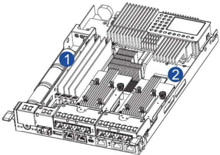
text_image
Technical diagram of an electronic device with labeled components, showing internal circuitry and connectors.NOTE: The super capacitor is partially charged when shipped. When you turn ON the system, the super capacitor will charge to its full capacity for a few minutes. If it is not charging, there may be a problem. Contact your system vendor immediately. You can also check the status of the super capacitor via EonOne or the firmware. Refer to the manuals for more details.
1.5 System monitoring features
This section describes the different types of system monitoring features that provide the operating status of each component.
1.5.1 Expansion enclosure support
Monitoring system
A managing GSa system is aware of the status of connected expansion system's components such as:
- Expander controller (presence, voltage, and thermal readings)
- PSU/cooling module
• Enclosure thermal sensor
• Service (the Service LED signals the specific enclosure) - Hard disk drives
Expansion system identifier
The managing system sets off the alarm and delivers the warning messages if there is a conflict between the expansion systems.
If more than one expansion system is connected to the managing GSa system, each needs a unique enclosure ID set using the rotary switch on the LED panel. For example, the firmware automatically disconnects the second expansion system if it is connected online and comes with an ID identical to the first expansion system.
NOTE: The expansion system IDs are numbers 1 to 15. For more details, see section 2.3.6 Expansion connections.
Cooling module speed adjustment
If any of the detected temperature readings breaches the temperature threshold, the firmware running on the managing GSa system automatically increases the rotation speed of all cooling fans.
Expansion enclosure status monitoring
When connecting with expansion systems, you can acquire the component status with other enclosures via a propriety enclosure monitoring service using the in-band connectivity. No additional management connection is required.
I^2C bus
The detection circuitry and temperature sensors are interfaced via a non-user-serviceable I²C bus. When the expansion systems are connected to GSa controllers, the component status is reported through in-band protocols over expansion links, which is managed by a proprietary enclosure service.
Firmware (FW) and EonOne
- Firmware: The firmware (FW) is preloaded and is used to configure the system. Access the FW via a terminal emulation program running on a management computer connected to the system's serial port.
- EonOne: EonOne is another browser-based GUI (graphic user interface) software that you can install into a local or remote computer and access via the network. The managing system communicates with the array via connection of the existing host links or the Ethernet link to the array's Ethernet port.
1.5.2 Audible alarms
The system comes with audible alarms that are triggered when certain active components fail or when specific controller or system thresholds exceed. Whenever you hear an audible alarm, you must determine the cause and solve the problem immediately.
Event notification messages indicate the completion or status of array configuration tasks and are always accompanied by two or three successive and prolonged beeps. You can turn off the alarm using the mute button on the front panel.
WARNING! Failure to respond when an audible alarm is set off can lead to permanent damage to the system. When you hear an audible alarm, solve the problem immediately.
1.6 Hot-swappable components
The system has a number of hot-swappable parts that you can change while the system is still online without affecting its operational integrity.
These hot-swappable components are user-maintained:
- PSU/cooling module
- Hard disk drive
- Controller modules
IMPORTANT! Only remove these hot-swappable components when replacement is needed.
NOTE: A normal airflow ensures sufficient cooling of the system and this can only be attained when all components are properly installed. Remember to only remove the failed component if there is already a replacement. For more information on replacing hot-swappable components, see chapter System maintenance.
Hardware installation
2
This chapter describes installing the modular components such as hard drives, cards, and other optional installation or connections such as expansions and rackmount.
2.1 Installation prerequisites
Take note of the following installation prerequisites before you start with the installation:
• Static-free installation environment
Install the system in a static-free environment to minimize the possibility of ESD (electrostatic discharge) damage.
- Component check
Before the installation, ensure that you received all required components by verifying the package contents with the Unpacking List document. This document is included in the package. If there are items missing and/or damaged, contact your vendor for a replacement.
- Hard drives
The SAS/SATA drives are purchased separately and must be available before the system installation.
- Memory modules
If you want to change the pre-installed DIMM modules, ensure that they are compatible and purchased from a qualified vendor. Contact your vendor for the list of compatible DIMMs.
- Cables
All cables that connect the system to the hosts are purchased separately. Contact your vendor for the list of compatible cables.
- Rackmount equipment
The rack slide rails are optional accessories. If you need to install it, see section 2.2.2 Installing the rackmount kit.
IMPORTANT! Install the system first to the rack or cabinet before installing the hard drives into the system.
Ensure that you are familiar with the exact position of each plug-in module and interface connector. Also, ensure to handle the cables with care when connecting between systems installed in the rack with a correct routing paths carefully planned. DO NOT bend or twist the cables as this may cause emission interference and accidental cable disconnection.
2.2 Installation procedures
This section details the installation procedures of the system, its components, and connections between equipment. The installation procedures in this section are in order, so it is strongly recommended that you follow the said order to reduce the time consumed during installation and prevent installation mistakes, technical mishaps, or physical injuries.
2.2.1 Unpacking the system
When your system package has arrived, check and confirm if the contents of your package are complete by referring to the Unpacking List document, which is bundled with in your package.
Accessory box contents
This box contains the following:
- Serial port cable
- Screws
- Quick installation guide
- Support CD (EonOne Management software and manual, firmware operation manual)
• Product utility CD (Hardware manual)
Pre-installed components
Below are the components that are pre-installed in the system:
- Controllers
- LED front panels
- PSU/cooling modules
- DIMM modules
• CBM (cache backup module) - Host board/s
Components that need user installation
You must do the following installation:
- Assembling of the system to the rack/cabinet
- Assembling the hard drives to the hard drive tray
• Cabling in between systems
NOTE: To install the system to the rack/cabinet, see section 2.2.2 Installing the rackmount kit.
2.2.2 Installing the rackmount kit
This section details the overview of the rackmount kits, assembly, and installation with the storage system.
IMPORTANT! Contact our technical support team if you need further help in installing your system/ enclosure to the rack.
NOTE: You can also watch this YouTube video on assembling the rackmount kit and installing the system to the rackmount.
Preparing the user-provided tools
Before assembling the slide rail kit, you must prepare the following tools:
• 1 x Medium-sized Phillips screwdriver
• 1 x Small-sized Phillips screwdriver
• 1 x Medium-sized flat blade screwdriver
Types of rackmount kit
There are two types of rackmount kit:
- Rack ear mount kit
- Slide rail kit
Rack ear mount kit contents
Check your rack ear mount kit for the following contents.
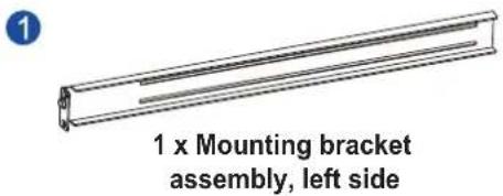
text_image
1 x Mounting bracket assembly, left side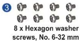
text_image
8 x Hexagon washer screws, No. 6-32 mm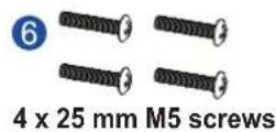
text_image
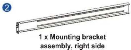
1 x Mounting bracket assembly, right side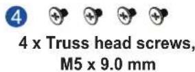
Assembling the rack ear mount kit
To assemble the rack ear mount kit:
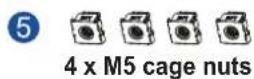
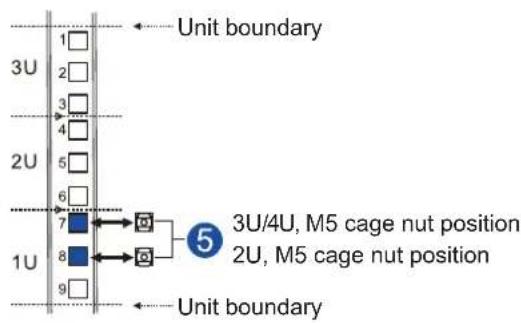
- Determine the position where the system will be installed to the front and rear rack posts, then insert the cage nuts into the designated holes on the front rack posts.
text_image
Unit boundary 3U 1 2 3 4 2U 5 6 7 8 9 3U/4U, M5 cage nut position 2U, M5 cage nut position Unit boundaryRear rack postFront rack post
text_image
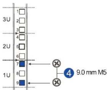
3U 1 2 3 4 2U 5 6 7 8 9 1U 9.0 mm M5- Install the fixed rails to the rear posts using the truss head screws.
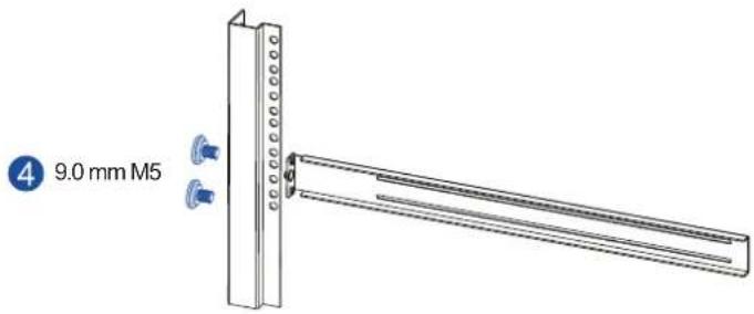
text_image
4 9.0 mm M5Installing the enclosure to the rack ear mount
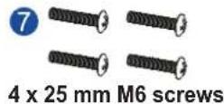
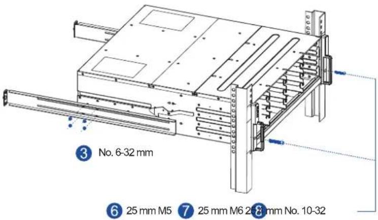
To install the enclosure to the rack ear mount, this requires an assistance of another person. While the other person holds the enclosure at the installation height, the other person secures the enclosure using four 25 mm M5 screws at the front and eight no. 6-32 screws on the side panels, four on each side.
text_image
③ No. 6-32 mm ⑥ 25 mm M5 ⑦ 25 mm M6 28 mm No. 10-32NOTE: The drawing of the enclosure is for reference only but the step is the same.
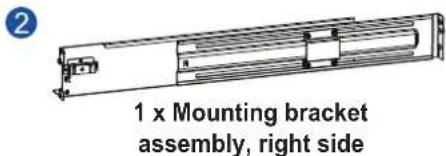
Slide rail kit contents
Check your slide rail kit for the following contents.
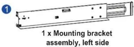
text_image
1 x Mounting bracket assembly, left side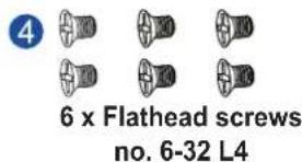
text_image
4 6 x Flathead screws no. 6-32 L4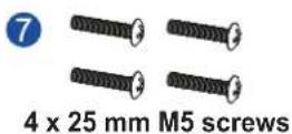
text_image
1 x Mounting bracket assembly, right side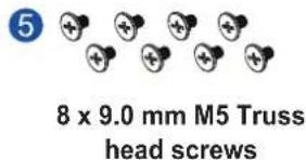
text_image
5 8 x 9.0 mm M5 Truss head screws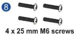

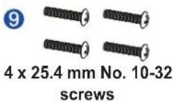
Assembling the slide rail kit
To assemble the slide rail kit:
- Determine the position where the system will be installed to the front and rear rack posts, then insert the cage nuts into the designated holes on the front rack posts.
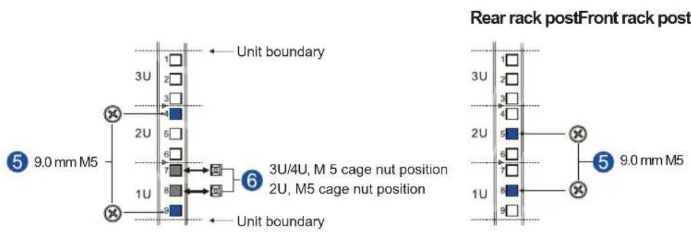
text_image
Rear rack postFront rack post Unit boundary 3U 1 2 3 4 2U 5 6 7 1U 8 9 Unit boundary 6 3U/4U, M 5 cage nut position 2U, M5 cage nut position Unit boundary 5 9.0 mm M5 9.0 mm M5- Loosen the four screws on the slide rails then adjust its length. After the length adjustment, secure the slide rails to the front and rear posts with the truss head screws.
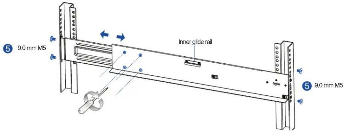
text_image
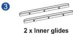
5 9.0 mm M5 Inner glide rail 5 9.0 mm M5- Attach the inner glides to both sides of the enclosure using the flathead screws no. 6-32.
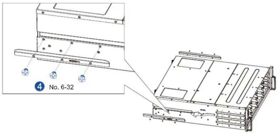
text_image
4 No. 6-32NOTE: The drawing of the enclosure is for reference only but the step is the same.
- With the assistance of another person, lift and insert the enclosure onto the slide rail. Ensure that the inner glides on both sides of the enclosure meet the inner glide rail.
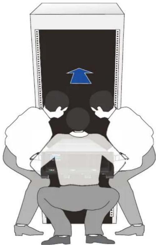
natural_image
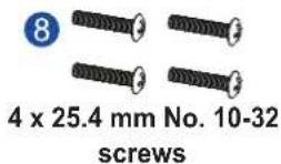
Illustration of three people sitting under a computer monitor with a blue arrow pointing upward (no text or symbols)- Secure the enclosure using the M5, M6, or no. 10-32 screws on the front.
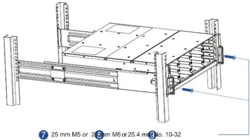
text_image
25 mm M5 or 25.9 mm M6 or 25.4 mm No. 10-32NOTE: The drawing of the enclosure is for reference only but the step is the same.
When the enclosure is already assembled to the cabinet, you can proceed to the next installation procedures of other components.
2.2.3 Installing the hard drives
This section gives you an overview of the hard drive requirements, installation, and important notices that you must take note.
NOTE: The hard drives are purchased separately.
IMPORTANT!
- Ensure to install the enclosure to the rack first before installing the hard drives to the enclosure's drive bay.
- You must install at least four (4) hard drives for RAID 5 configuration or five (5) hard drives for RAID 6 configuration to create an initial volume.
Hard drive installation prerequisites
When purchasing hard drives, ensure to consider the following factors:
- Capacity (Mb/Gb)
Purchase the hard drives that have the same capacity. This main storage uses the least common denominator approach, which means that the maximum capacity used in each drive to create a RAID array is the maximum capacity of the smallest drive. We strongly suggest to use large storage capacity hard drives.
IMPORTANT!
- The hard drives may carry different block numbers, which means that the capacity may not be the same even if they are of the same model with the same rate capacity made by the same manufacturer.
- When configuring the hard drives into a RAID array, you can use a smaller capacity as the maximum disk capacity in every hard drive. For configuration options, refer to the interface-specific firmware manual that came with your enclosure.
- Profile
The drive trays and bays of the system are designed for 2.5-inch hard drives.
- Drive type
The system uses SAS, near-line SAS, and SATA hard drives.
IMPORTANT!
- Ensure that you purchase the correct hard drives.
- If you prefer using SATA hard drives in the attached expansions, ensure that you purchase MUX kits.
Understanding the MUX kit's port mechanism
If you install a SATA hard drive in a dual-controller system, this may require an MUX board. The MUX board is paired with a hard drive in order to switch data signals between controllers A and B's signal ports.
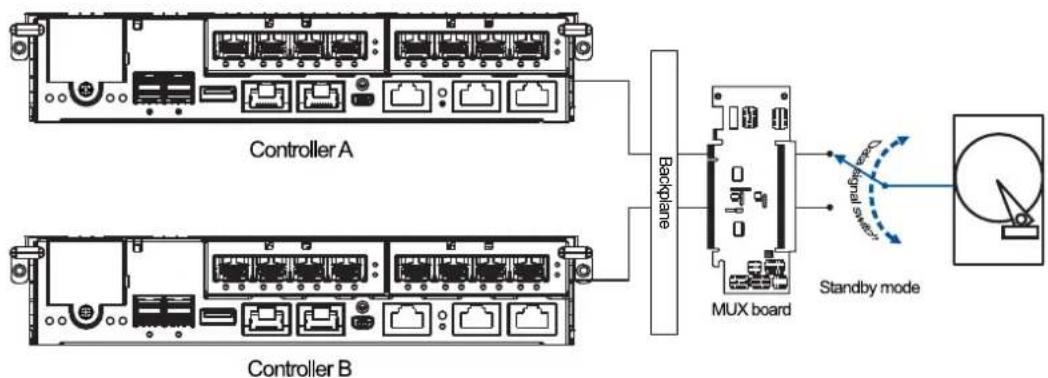
text_image
Controller A Backplane MUX board Standby modeUnder normal circumstances, the controller B's signal ports is in standby mode.
SAS and SATA interfaces
The SAS interface features a dual-ported connectivity with pins on both sides of its connector while the SATA drives have only one port. In a redundant-controller system, the MUX-supported drive trays must be separately purchased and applied. The single-controller expansion systems do not require an MUX kit.

text_image
Data port Keying notch SAS interface Power connector Data port SATA interface Power connectorIMPORTANT!
- ONLY install the drive trays to the system if the system is already mounted to the rack. If the hard drives are installed to the system before mounting to the rack, the system will be heavy to mount and possible impact during installation may damage the hard drives.
- Handle the disk drives with extreme care and observe all ESD prevention procedures when installing the hard drives.
- ONLY use the screws that are bundled in the system package. Securing the drives with longer screws may damage them.
Hard drive designation
Get to know the exact order of the hard drives to avoid removing the wrong drives out of the enclosure.

text_image
1 2 3 4 5 6 7 8 9 10 11 12 13 14 15 16 17 18 19 20 21 22 23 24 25GSa 3025
IMPORTANT! Install at least four hard drives for RAID 5 and five hard drives for RAID 6 to create an initial volume.
Installing the hard drive into the drive tray and enclosure
To install the hard drive into the drive tray and enclosure, follow the steps below:
- Press the release button to open the spring handle, then gently pull out the tray.
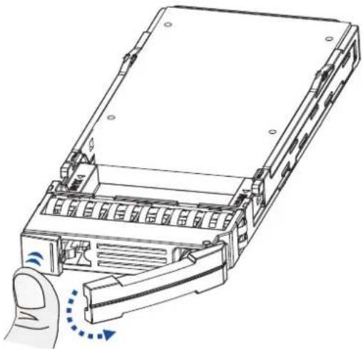
natural_image
Diagram of a hard drive with a hand pressing a button, showing internal components and a blue circular arrow indicating rotation (no text or symbols present)- Place the hard drive into the tray.
With MUX board:
a. Attach the MUX board to the drive.
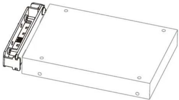
natural_image
Technical line drawing of a rectangular electronic device with mounting holes and internal components (no text or symbols)b. Place the hard drive on the tray (A), then secure the clips to both sides of the tray (B).
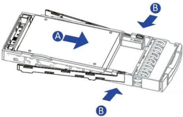
text_image
A B BWithout MUX board:
Place the hard drive on the tray (A), then secure the clips to the side of the tray (B).
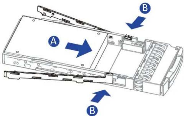
text_image
A B B- Insert the assembled hard drive and tray to the enclosure with the spring handle open.
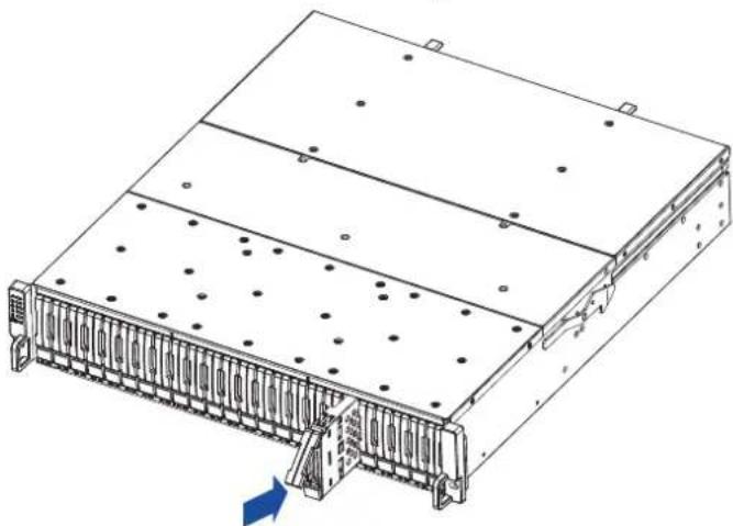
natural_image
Technical line drawing of a server rack with mounting holes and ventilation slots (no text or symbols)- Close the spring handle when the drive is fully inserted to the bay.
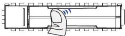
natural_image
Diagram of a mechanical component with a hand interacting with it, showing no text or symbols.2.2.4 Installing the host boards
NOTES:
- A downtime may occur when upgrading the controller/host board.
- To add or replace a host board, the firmware automatically restores the default factory settings of your system.
To install a host board:
- Shut down your system.
- On the controller that you want to add a host board, unfasten the retention screw located under the ejection levers.
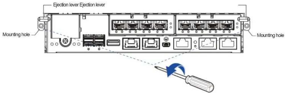
text_image
Ejection lever Ejection lever Mounting hole Mounting hole- Push down the ejection levers to dislodge the controller from the system (A), then pull to remove from the enclosure (B).
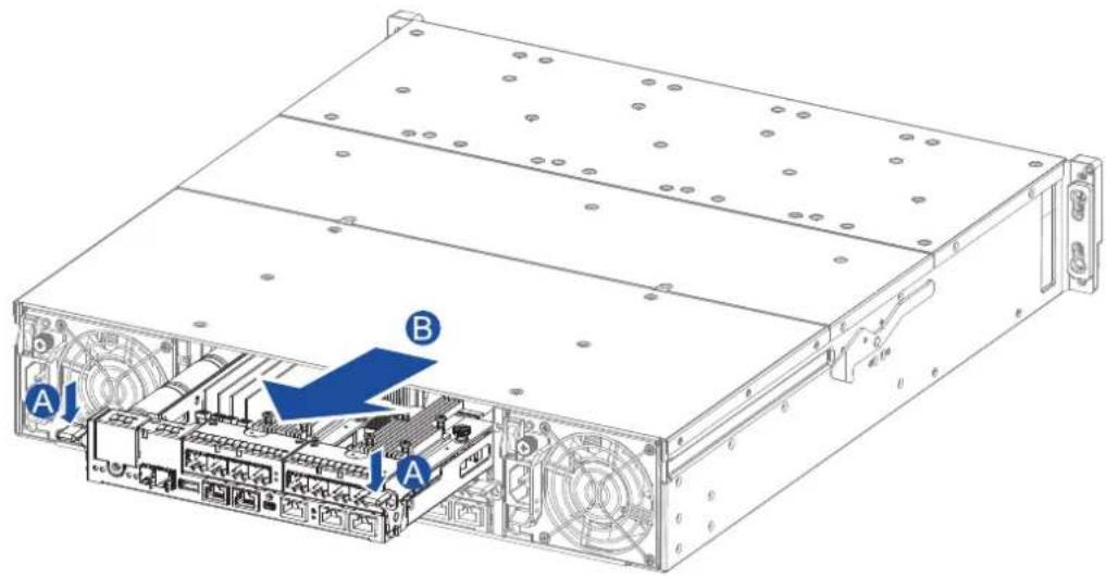
text_image
Technical diagram of a server rack with labeled components A and B, showing internal circuit connections and ventilation slots.- Remove the screws from the host board slot.
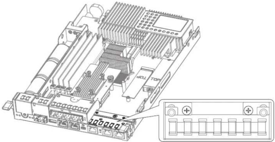
natural_image
Technical line drawing of an electronic circuit board with labeled ports and connectors (no readable text or symbols)- Orient the new host board's guide pin hole to the controller's guide pin, place it carefully, then tighten the thumb screw to secure in place.
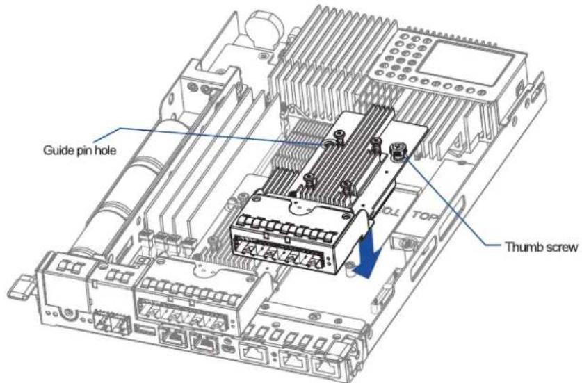
text_image
Guide pin hole TOP Thumb screw-
Insert the controller carefully into the controller module slot. When you feel a contact resistance, then push the controller with a small but careful force.
-
Move the ejection levers upwards to secure the controller to the enclosure, then fasten the two retention screws to the controller's mounting holes under the ejection levers.
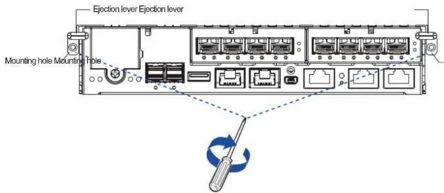
text_image
Ejection lever Ejection lever Mounting hole Mounting hole2.3 Connections
This section details the connection procedures of GSa systems to the expansions, power source, connection status, topologies, and other connection configurations.
2.3.1 General considerations in connecting devices
When selecting the number of hard drives to assemble a logical drive, the host channel bandwidth and the performance of each drive must be considered. It is a good practice that you calculate the performance against the host port bandwidth when designing an application topology.
For example, if eight drives are included in a logical drive and is associated with a host ID (LUN mapping), the combined performance of this logical drive must estimate the channel bandwidth. If two 6-drive logical arrays are associated with two IDs residing in a single host channel, there may be a trade-off with the performance.
If your system comes with a total of eight or more host ports, we recommend that you use more disk drives to an expansion so that you can create a host-port that corresponds to 6-member logical drives (RAID 5) or 8-member logical drives (RAID 6). These logical drives bring up the bandwidth of each host.
You must also take note of these considerations:
- A spare drive that carries no data stripes and does not contribute to disk-level performance. For performance data information of your hard drive, refer to its documentation.
- Disk drives in the same logical array must have the same capacity, but it is preferred that all drives in the chassis have the same capacity.
- Disk drives in the same logical drive must have the same capacity, but it is preferred that all disk drives in a chassis have the same capacity. Tiered storage configuration is supported in this setup. However, you must not include both SAS and SATA drives in a logical drive.
- A spare drive must have a minimum capacity equivalent to the largest drive that needs replacement. If the capacity of the spare drive is less than the capacity of the drive to be replaced, the controller will not proceed with the failed drive rebuild.
- When rackmounting, leave enough space for the cables. DO NOT bend them to a diameter of less than 76 mm (3 inches).
- When connecting between devices, follow all the specifications. Pay attention to the signals and avoid electronic noise from adjacent interfaces. DO NOT put power cords on optical cables.
- Route the cables away from places where it can be damaged by other devices such as fan exhaust or foot traffic.
- DO NOT over-tighten, twist, or bend the cables.
Configuring the host-side topologies
When configuring host-side topologies, avoid the points of failure. It is recommended that the host ports are connected to at least two HBAs.
NOTES:
- To manage the fault-tolerant data paths and optimize data throughput on multiple data paths, you must apply MPIO software or other multipathing utilities such as Linux Device Mapper.
- Host port channel designation may vary by system. Refer to the topologies of this manual to create your own connections that suit your needs.
Configuring the host-side parameters
For the host-side parameters, we strongly recommend that you use the default settings of your system. If you need to adjust the host-side parameters, consult your on-site technical personnel or seek technical support from your vendor.
Familiarizing the Maximum Concurrent Host LUN Connection (Nexus in SCSI)
The menu option Max Number of Concurrent Host-LUN Connection allows you to set the maximum number of concurrent host LUN connections. This is the arrangement of the controller internal resources to use with a number of current host nexus.
For example, if you have four hosts (A, B, C, and D) and four host IDs/LUNs (IDs 0, 1, 2, and 3) in a configuration, where:
- Host A accesses ID 0 (one nexus)
- Host B accesses ID 1 (one nexus)
- Host C accesses ID 2 (one nexus)
- Host D accesses ID 3 (one nexus)
These connections are queued in the cache, which are called four nexus. If there is an I/O in the cache with these four nexus and another host I/O comes with a nexus different from the four in the cache (e.g. host A accesses ID 3), the controller returns as busy. This happens with the concurrent active nexus. If the cache is cleared, it accepts four different nexus again. Many I/O operations can be accessed via the same nexus.
Knowing the Maximum Queued I/O Count
The menu option Maximum Queued I/O Count allows you to configure the maximum number of I/O operations per host channel that can be accepted from the servers. The predefined range is from 1 to 1024 I/O operations per host channel. You can also choose Auto, which sets the automatic configuration. The default value is 256 I/O operations.
The appropriate setting for this option depends on how many I/O operations the attached servers are performing. This varies according to the amount of the host memory present as well as the number of drives and their respective sizes. Usually, the optimum performance occurs from using Auto or 256 settings.
For more information, refer to the firmware manual that came with your system.
2.3.2 Fibre-Host connections
The Fibre Channel standard allows optical connections. The optical cables are used over long distances and have been proven to be more reliable. Due to the demands of high transfer rates, optical cables are preferred for a 4 Gbps, 8 Gbps, or 16 Gbps fiber connectivity, as they are not vulnerable to EMI.
The fibre host ports are connected to fibre channel host adapters (HBA) that feature SFP interface with full duplex transfer support in a PCIe interface. For the latest certified items, contact the vendor near you.
WARNING!
- All fibre cables are sensitive and must be handled with care. To avoid interference, the cabling path must be carefully planned without the cables getting bent.
- Lasers are hazardous and may cause blindness or permanent eye damage. Use them with utmost caution. Never look directly when lasers are turned on or operating.
Detecting auto speed
Speed auto-detection is specified by the Fibre channel standard. If a 16 Gbps port is connected to an 8 Gbps port, the speed slows down at 8 Gbps. If there are 16 Gbps ports on both ends of the link, the speed runs at 16 Gbps.
SFP/SFP+ transceivers
An SFP transceiver converts electrical data signals into light signals then transfers these signals transparently via the optical fiber. A transceiver provides bi-directional data links, a laser transmitter (for fiber optic cables), LC connector, and a metal enclosure to lower the EMI.
Other features of a typical SFP transceiver include a single power supply, low power dissipation, and hot-swap capability. It is also important that the transceiver you use meets the FC performance and reliability specifications.
WARNING! The SFP transceiver has a laser diode featuring a Class 1 laser. To ensure safety, DO NOT remove any covers or attempt access of the inside of the device. If problems arise or if you need technical service, contact a qualified personnel.
FC port dust plugs
Each FC port comes with a dust plug. Remove these plugs ONLY when you insert an SFP transceiver.
NOTE: Contact your vendor for the list of compatible SFP/SFP+ transceivers.
Fibre-host topologies
The fibre-host standard supports three topologies:
- Point-to-point topology
A direct connection between two fibre-channel devices, the simplest among the three topologies.
• FC-AL (Fibre Channel Arbitrated Loop)
The fibre-channel devices are all connected to a loop. Each device is assigned to an AL_PA (Arbitrated Loop Physical Address). FC-AL supports 124 devices in a single loop. This is the most commonly-used topology among the three.
- Fabric switch
This topology can support up to 224 fibre-channel devices and allows multiple devices to communicate simultaneously. A fibre switch is required to implement this topology.
IMPORTANT! If different servers need to access your logical drive, file locking, FC switch zoning, port binding, and multipath access control configurations are necessary.
Fibre cabling
Before you set up your fibre cabling connection, you must:
a. Create a configuration plan. In addition to cabling topologies and the list of networking components, you must also include the firmware and software maintenance details.
b. Confirm that your fibre-channel cable's loop measures 6 inches or longer.
c. Ensure proper airflow and keep the cables away from ventilation outlets.
To connect devices using fibre cable:
- Take out the SFP transceiver module from the static protective package.
- Remove the dust plug from the transceiver module.
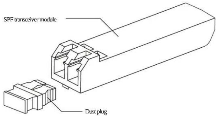
text_image
SPF transceiver module Dust plug- Insert the SFP module into one of the system host ports. The module will snap into place.
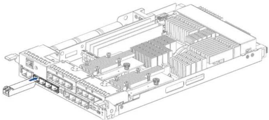
natural_image
Technical line drawing of an electronic device chassis with internal components and connectors (no text or symbols)NOTE: The drawing of the controller is for reference only. Look for the actual system host ports in your GSa 3000 system.
- Remove the two protective caps from the LC-to-LC type cable. Save the protective caps for future use.
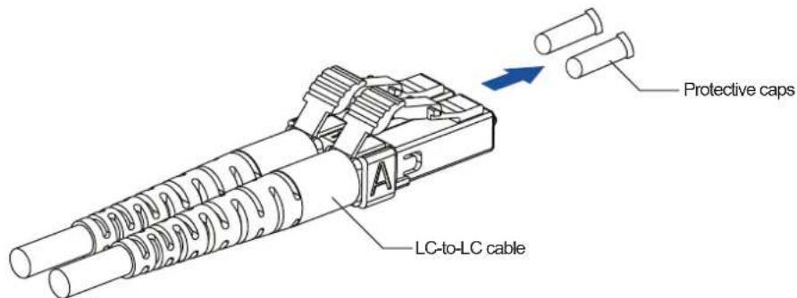
text_image
Protective caps LC-to-LC cable- Insert the LC-to-LC cable to the SFP transceiver module already connected to the system. You can hear a clicking sound, securing the cable in place.
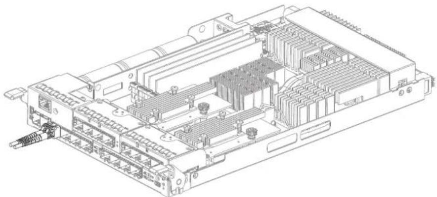
natural_image
Technical line drawing of an electronic circuit board with internal components (no text or symbols)NOTE: The drawing of the controller is for reference only. Look for the actual system host ports in your GSa 3000 system.
- Remove the protective caps on the other end of the cable, then connect to an SFP transceiver module on a Fibre Channel switch port or a Fibre Channel host bus adapter (HBA) port.
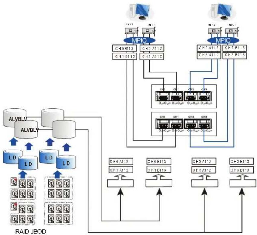
Simple end-to-end connection
This connection type shows a simple end-to-end connection, with each SFP port is connected to a host adapter. Multiple logical drives. logical volumes, and logical partitions are created and each partition is mapped to a corresponding host channel ID/LUN combination.
flowchart
graph TD
    subgraph RAID_JBOD
        A["ALVBLV"] --> B["ALVBLY"]
        B --> C["LD"]
        C --> D["LD"]
        D --> E["LD"]
        E --> F["QA"]
    end

    subgraph MPIO
        G["CH0 B113"] --> H["CH1 B113"]
        I["CH0 A112"] --> J["CH1 A112"]
        K["CH2 A112"] --> L["CH3 A112"]
        M["CH2 B113"] --> N["CH3 B113"]
    end

    G --> O["QA"]
    H --> P["QA"]
    J --> Q["QA"]
    L --> R["QA"]
    N --> S["QA"]
    O --> T["QA"]
    P --> U["QA"]
    Q --> V["QA"]
    R --> W["QA"]
    S --> X["QA"]
    T --> Y["QA"]
    U --> Z["QA"]
    V --> AA["QA"]
    W --> AB["QA"]
    X --> AC["QA"]
    Y --> AD["QA"]
    Z --> AE["QA"]
    AA --> AF["QA"]
    AB --> AG["QA"]
    AC --> AH["QA"]
    AD --> AI["QA"]
    AE --> AJ["QA"]
    AF --> AK["QA"]
    AG --> AL["QA"]
    AH --> AM["QA"]
    AI --> AN["QA"]
    AJ --> AO["QA"]
    AK --> AP["QA"]
    AL --> AQ["QA"]
    AM --> AR["QA"]
    AN --> AS["QA"]
    AO --> AT["QA"]
    AP --> AU["QA"]
    AQ --> AV["QA"]
    AR --> AW["QA"]
    AS --> AX["QA"]
    AT --> AY["QA"]
    AU --> AZ["QA"]
    AV --> BA["QA"]
    AW --> BB["QA"]
| Channels Controller A Controller B | |
| Host CH0, CH1, CH2, CH3 CH0, CH1, CH2, CH3 | |
| Configuration information | |
| Number of controllers 2 | |
| Host servers 2 | |
| Data path connection | Fault-tolerant data paths |
NOTE: You need a multipathing software such as MPIO or Linux Device Mapper to control and optimize the access to logical drives via multiple data paths.
DAS (Direct-Attached) connection
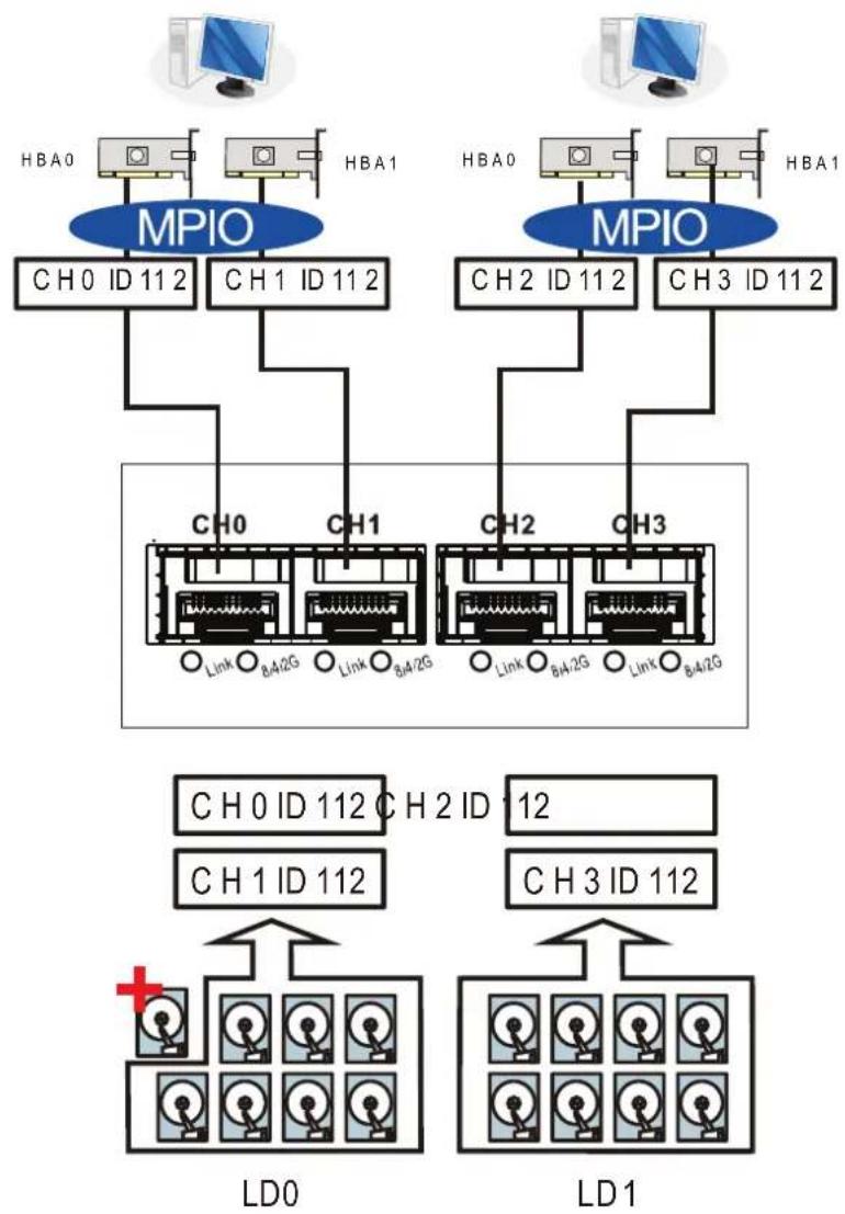
This connection has more disk drives over SAS expansion links. With this connection, you can create more logical groups of drives. These logical drives use more host channel IDs or LUN numbers.
The two logical drives in the illustration below cannot equate the full power of the system. You can attach one or two more expansion enclosures to achieve more end-to-end performance.
H2ID
12
| Channels Controller A |
| Host CH0, CH1, CH2, CH3 |
| Configuration information |
| Number of controllers 1 |
| Host servers 2 |
| Data path connection Simple end-to-end connections with fault-tolerant pairs |
NOTE: If a server has multiple data paths to a main storage, a multipathing software such as MPIO, is needed.
Switched fabric connection in dual controller
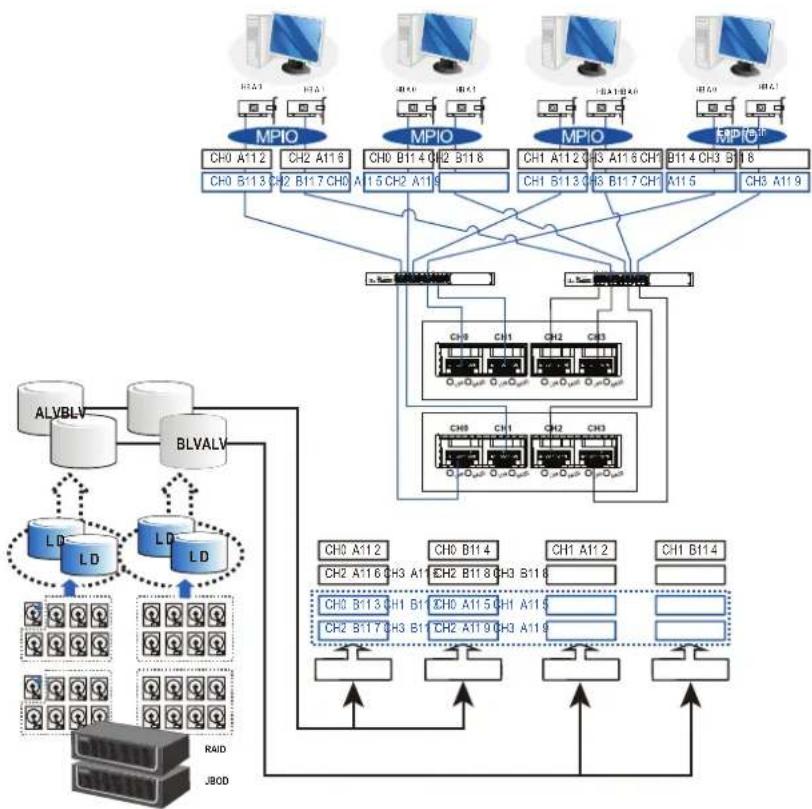
In this type of connection, the channel link bypass is provided by external FC switches. Each application server shown in the illustration below is equipped with two HBAs with FC links, connecting via two FC switches to the SFP ports on individual controllers.
flowchart
graph TD
    subgraph MPIOS
        A1["CH0 A112"] --> B1["CH0 B113"]
        A2["CH2 A116"] --> B2["CH2 B117"]
        A3["CH0 B114 0"] --> B3["CH2 B118"]
        A4["CH1 A112 0"] --> B4["CH1 B113"]
        A5["CH3 A116 CH1"] --> B5["CH3 B117 CH1"]
        A6["B114 CH3 B"] --> B6["CH3 A119"]
    end

    subgraph ALVBLV
        C["ALVBLV"] --> D["BLVALV"]
        D --> E["LD"]
        D --> F["LD"]
        E --> G["Raid"]
        F --> H["J80D"]

    subgraph BLVALV
        I["BLVALV"] --> J["LD"]
        I --> K["LD"]
        J --> L["L0"]
        J --> M["L0"]
        J --> N["L0"]
        K --> O["L0"]
        K --> P["L0"]
        L --> Q["QA"]
        M --> R["QA"]
        N --> S["QA"]
    end

    subgraph DATA Flow
        T["Ch0 A112"] --> U["CH2 A116 CH3 A11"]
        T --> V["CH2 B114 CH3 B11"]
        T --> W["CH0 B113 CH1 B1"]
        T --> X["CH2 B117 CH3 B1"]
        T --> Y["CH0 A115 CH1 A115"]
        T --> Z["CH2 A119 CH3 A119"]
    end

    style MPIOS fill:#f9f,stroke:#333
    style ALVBLV fill:#ccf,stroke:#333
    style BLVALV fill:#cfc,stroke:#333
    style DATA Flow fill:#ffc,stroke:#333
| Channels Controller A | Controller B | |
| Host | CH0, CH1, CH2, CH3 | CH0, CH1, CH2, CH3 |
| Configuration information | ||
| Number of controllers | 2 | |
| Host servers | 4 (or more via FC switches) | |
| FC switches | 2 (or 1 into 2 zones | |
| Data path connection | Fault-tolerant data paths | |
Each logical partition is redundantly mapped to multiple host channel IDs in an AAPP (Active-Passive-Passive-Passive) configuration. Logical volumes are managed by either controller A or controller B. The passive IDs will only become functional when a single controller fails in the system.
The MPIO driver is needed on the application servers. This driver communicates with the system firmware and performs load balance and automated distribution of I/Os across the preferred paths (active IDs on data paths). TPGS (Target Port Group Service) is supported so that the I/Os are routed to the preferred paths.
You can refer to the ID tags on the host links to see the related logical volume mapping and cable links routing paths. The connection above can withstand failure of a single component such as controller, HBA card, cable, or FC switch.
Switched fabric connection in single controller
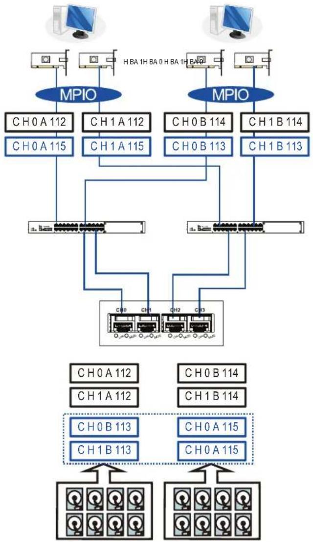
In this type of connection, each SFP port is connected to an FC switch then to the host adapters. Each logical partition is mapped to a single host channel ID. If you prefer path redundancy, you can map a logical partition to IDs residing on two different channels.
flowchart
graph TD
    subgraph_Client_Computer1["Client 1"]
        A1["Computer"] --> MP1["MPIO"]
        A2["Computer"] --> MP2["MPIO"]
        A3["Computer"] --> MP3["MPIO"]
    end

    subgraph_Client_Computer2["Client 2"]
        B1["Server"] --> CH0A112["CH0A112"]
        B2["Server"] --> CH1A115["CH1A115"]
        B3["Server"] --> CH0B114["CH0B114"]
        B4["Server"] --> CH1B114["CH1B114"]
        B5["Server"] --> CH1B113["CH1B113"]

    MP1 --> CH0A112
    MP1 --> CH1A112
    MP2 --> CH0B114
    MP2 --> CH1B114
    MP3 --> CH0B113
    MP3 --> CH1B113

    CH0A112 --> CH0B113
    CH0B113 --> CH0A115
    CH0B114 --> CH0A115
    CH0A115 --> CH0B113
    CH0B114 --> CH0A115
    CH0A115 --> CH0B113
    CH0B114 --> CH0A115
    CH0A115 --> CH0B113
    CH0B114 --> CH0A115
    CH0A115 --> CH0B113
    CH0B114 --> C00["CH00"]
    CH0A115 --> C00["CH00"]
    style MP1 fill:#f9f,stroke:#333
    style MP2 fill:#f9f,stroke:#333
    style MP3 fill:#f9f,stroke:#333
    style C00 fill:#ccf,stroke:#333
    style C00 fill:#cfc,stroke:#333
LD 0 LD 1
| Channels Controller A | |
| Host CH0, CH1, CH2, CH3 | |
| Configuration information | |
| Number of controllers 1 | |
| Host servers 4 | |
| Data path connection | The data paths are connected to one or more FC switches. The SAN management measures, such as switch zoning and port binding, must be taken to avoid multiple servers from accessing the same LUN. |
If multiple servers detect a mapped volume, you have to avoid access contention using file locking software, port binding, or zoning feature of the FC switches, which limits the access from host to a specific LUN. If you have two servers in a clustered configuration, the clustering software performs the access control.
IMPORTANT!
- We suggest you to use an enclosure-specific spare drive to prevent it from participating in the rebuild of a logical drive on another enclosure. You can refer to the ID tags on the host links to see the related LUN mapping and cable links routing paths.
- You need MPIO driver to manage the access via two different HBA ports. This driver communicates with the system firmware and performs load balance and automated distribution of I/O.
2.3.3 SAS - host connections
This section details about the connections between SAS and host using SAS cables. The SAS cables (8 pairs of 28 mm AWG) are characterized by the following:
- 100 Ohms
- Black color
- UL-approved, lead free 50 cm, 120 cm, or 170 cm in length
- Connectors must be secured to the receptacle of the chassis using a latching mechanism
WARNING! The SAS cables are sensitive and must be handled with care. To prevent interference within the rackmount, the cable routing path must be carefully planned and the cables must not be bent.
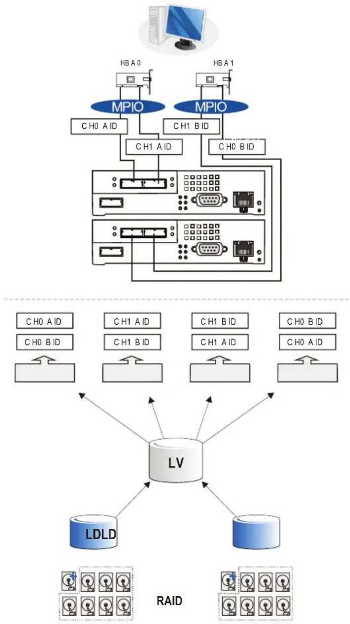
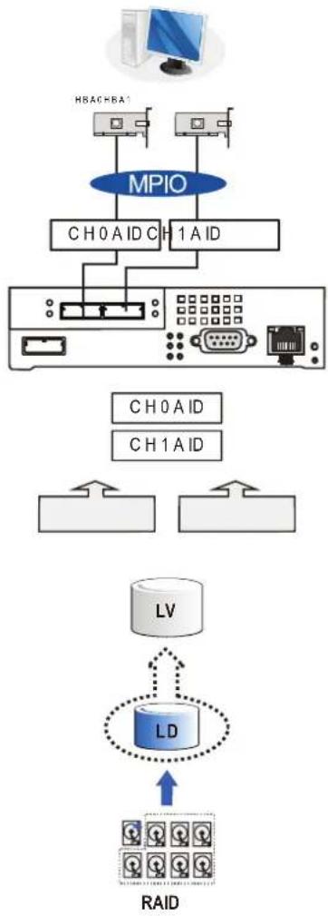
DAS (Direct-Attached Storage) connection with Redundant host path
- Dual-controller models
flowchart
graph TD
    subgraph Server
        A["Computer"] --> B["MB"]
        C["MB"] --> D["MPIO"]
        E["MB"] --> F["MPIO"]
        G["MB"] --> H["MB"]
        I["MB"] --> J["MB"]
        K["MB"] --> L["MB"]
        M["MB"] --> N["MB"]
        O["MB"] --> P["MB"]
        Q["MB"] --> R["MB"]
        S["MB"] --> T["MB"]
        U["MB"] --> V["MB"]
        W["MB"] --> X["MB"]
        Y["MB"] --> Z["MB"]
        AA["MB"] --> AB["MB"]
        AC["MB"] --> AD["MB"]
        AE["MB"] --> AF["MB"]
        AG["MB"] --> AH["MB"]
        AI["MB"] --> AJ["MB"]
        AK["MB"] --> AL["MB"]
        AM["MB"] --> AN["MB"]
        AO["MB"] --> AP["MB"]
        AQ["MB"] --> AR["MB"]
        AS["MB"] --> AT["MB"]
        AU["MB"] --> AV["MB"]
        AW["MB"] --> AX["MB"]
        AY["MB"] --> AZ["MPIO"]
        BA["MPIO"] --> BB["C H0 A ID"]
        BC["MPIO"] --> BD["C H1 A ID"]
        BE["MPIO"] --> BF["C H1 B ID"]
        BG["MPIO"] --> BH["C H0 B ID"]
    end

    subgraph Server
        BI["C H0 A ID"]
        BJ["C H0 B ID"]
    end

    subgraph Cloud
        BK["C H0 A ID"]
        BL["C H1 A ID"]
        BM["C H1 B ID"]
        BN["C H1 A ID"]
        BO["C H0 B ID"]
        BP["C H0 A ID"]
    end

    subgraph Cloud
        BQ["C H0 A ID"]
        BR["C H1 A ID"]
        BS["C H1 B ID"]
        BT["C H1 A ID"]
        BU["C H0 B ID"]
        BV["C H0 A ID"]
    end

    subgraph Cloud
        BW["LV"]
    end

    subgraph Cloud
        BX["LDLD"]
        BY["RDID"]
    end

    subgraph Cloud
        BZ["RDID"]
    end

    subgraph Cloud
        CA["RDID"]
    end
- Single-controller models
flowchart
graph TD
    A["Computer"] --> B["MPIO"]
    B --> C["CH0AID CH1AID"]
    C --> D["Server"]
    D --> E["Antenna"]
    F["HLA/BHA1"] --> B
    G["HLA/BHA2"] --> B
    H["HLA/BHA3"] --> B
    I["HLA/BHA4"] --> B
    J["HLA/BHA5"] --> B
    K["HLA/BHA6"] --> B
    L["HLA/BHA7"] --> M["CH0AID CH1AID"]
    N["HLA/BHA8"] --> O["LV"]
    P["HLA/BHA9"] --> Q["LD"]
    R["HLA/BHA10"] --> S["RAID"]
    T["HLA/BHA11"] --> U["RAID"]
    V["HLA/BHA12"] --> W["RAID"]
NOTES:
- With more hard drives over SAS expansion links, you can create more logical groups of drives. Avail the logical partitions using more LUNs.
- If your operating system is Windows ^ 2003 server, you need a multipathing software such as MPIO or Linux Device Mapper to control and optimize the access to logical drives via multiple data paths.
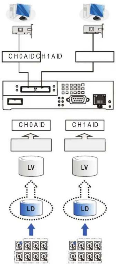
DAS (Direct-Attached Storage) connection to two servers
flowchart
graph TD
    A["Client 1"] --> B["CH0AID"]
    C["Client 2"] --> D["CH1AID"]
    B --> E["Server"]
    D --> E
    E --> F["LV"]
    E --> G["LV"]
    F --> H["LD"]
    G --> I["LD"]
    H --> J["Image Box with UP arrow"]
    I --> K["Image Box with UP arrow"]
RAID
NOTE: If you want your LUN to be accessible by multiple hosts, use locking or multipath access control.
2.3.4 Ethernet - host connections
Before performing the connections between Ethernet and host, take note of the following requirements:
- Ethernet cables are user-supplied. We recommend you to use CAT5e shielded STP type network cables or cables with better performance types (important for meeting the requirements imposed by emission standards).
- Use of straight-through Ethernet cables with RJ-45 plugs.
- Use of cross-over cables. These cables are automatically detected and rerouted for a valid connection.
See below the list of connection types:
- Directly to iSCSI initiators (software or hardware) or via the Gigabit Ethernet switches.
- To servers equipped with iSCSI HBA, preferably a hardware TOE (TCP/IP Offload Engine) card, then to client stations with an Ethernet NIC or iSCSI HBA.
- The system presents its logical volumes via SCSI-like IDs and LUNs. These RAID volumes then appear as iSCSI targets via the network.
IMPORTANT! Even though the iSCSI initiator software is a cost-effective way of building an iSCSI SAN, this software initiator adds additional workload to the server CPU. We recommend you to apply iSCSI HBAs that come with TCP/IP offload engines in order to reduce overhead.
Network and host connection topologies
The iSCSI host ports must be connected to Ethernet network devices and iSCSI initiators that comply with IEFT iSCSI standard (RFC 3720). The network connection of the iSCSI ports is flexible. The use of network connecting devices, subnet, name servers, or iSCSI management software varies from case to case.
Note that the host NIC ports and the storage system's iSCSI host ports must be configured in the same subnet, and the following:
- Use the Ethernet Management port for management purposes only such as EonOne or telnet console. This port must not be used for I/O processes.
- Configurations such subnet or virtual LAN can separate iSCSI host links, decrease overhead, and eliminate the impact of link failure.
- Multiple arrays or logical partitions can be created and made available separately via different IDs or LUNs on host ports. Usually, a RAID5 logical drive of 8 members sometimes brings optimal array performance.
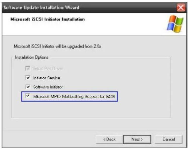
IMPORTANT! If you are using Microsoft's software initiator, uncheck the embedded MPIO function when installing the software as the MPIO selection creates conflict with MPIO driver.
text_image
Software Update Installation Wizard Microsoft iSCSI Initiator Installation Microsoft iSCSI Initiator will be upgraded from 2.0x Installation Options ✓ Virtual Port Driver ✓ Initiator Service ✓ Software Initiator ✓ Microsoft MPIO Multipathing Support for iCSI < Back Next > CancelHigh availability IP SAN with redundant controller
flowchart
graph TD
    subgraph HBA
        A["Computer"] --> B["MPIO"]
        C["Computer"] --> D["MPIO"]
    end
    subgraph MPIO
        E["VLAN 0"] --> F["VLAN 1"]
    end
    G["LD 0 LD 1 LD 2 LD 3"] --> H["CH0 CH1 CH2 CH3"]
    I["LD 3"] --> J["CH0 CH1 CH2 CH3"]
    K["Ch0 AID* CH1 AID* CH2 BID* CH3 BID* CH0 BID CH1 BID CH2 AID CH3 AID"] --> L["Ch0 CH1 CH2 CH3"]
    M["Ch0 CH1 CH2 CH3"] --> N["Ch0 CH1 CH2 CH3"]
    O["Ch0 CH1 CH2 CH3"] --> P["Ch0 CH1 CH2 CH3"]
    Q["Ch0 CH1 CH2 CH3"] --> R["Ch0 CH1 CH2 CH3"]
    S["Ch0 CH1 CH2 CH3"] --> T["Ch0 CH1 CH2 CH3"]
    U["Ch0 CH1 CH2 CH3"] --> V["Ch0 CH1 CH2 CH3"]
    W["Ch0 CH1 CH2 CH3"] --> X["Ch0 CH1 CH2 CH3"]
    Y["Ch0 CH1 CH2 CH3"] --> Z["Ch0 CH1 CH2 CH3"]
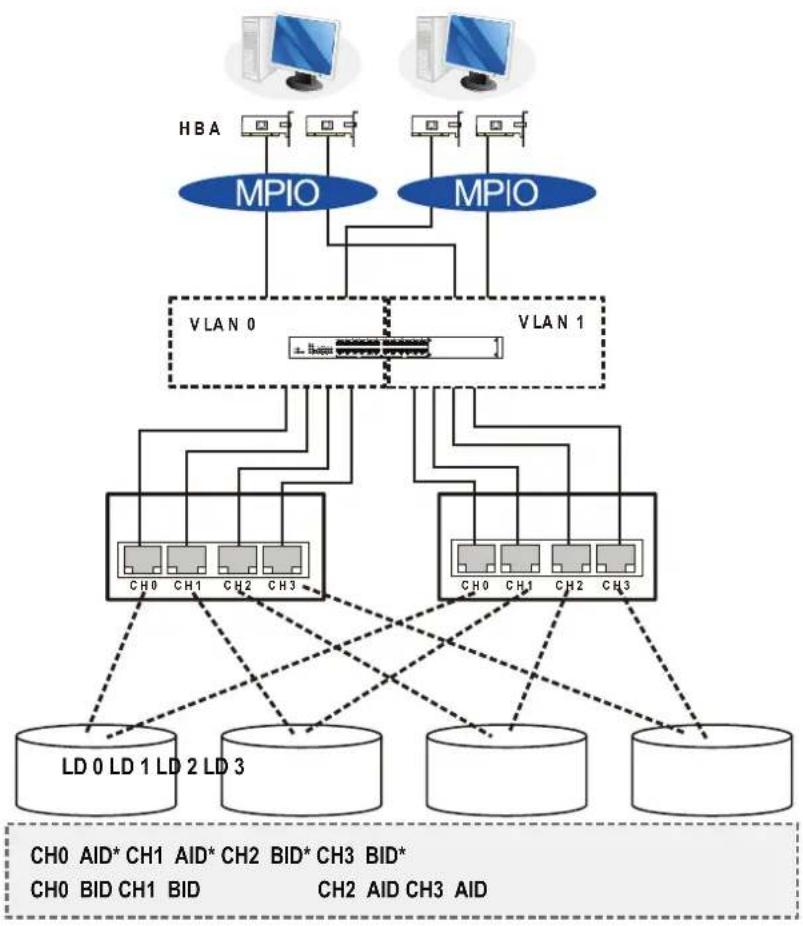
| Component Description | |
| Storage system Redundant controllers with a total of 8 host ports | |
| HBA | iSCSI initiators, preferably PCIeTOE (TCP/IP offload engine)-capable cards |
| GbE cables GbE network cables | |
| GbE switch Ports divided into 2 virtual LANs to separate access from host to targets | |
| Software | MPIO to manage the fault-tolerant paths with failover/failback and load balance capabilities. Use MPIO multipathing software for the operating system to identify the alternative paths to the same logical drive. |
| RAID configuration | This configuration does not support remote replication functionality.To set up remote replication, refer to High Availability IP SAN with Port Trunk (Remote Replication Enabled) or High Availability IP SAN with Port Trunk (Remote Replication Enabled).Four logical drives (each logical drive has four member drives).You can include the drives from the expansion systems for better performance.LD0 mapped to CH0 AID and CH0 BID; LD assigned to controller ALD1 mapped to CH1 AID and CH1 BID; LD assigned to controller ALD2 mapped to CH2 AID and CH2 BID; LD assigned to controller BLD3 mapped to CH3 AID and CH3 BID; LD assigned to controller B |
| CH0 AID | |
| CH1 AID | Logical drive assignment |
| CH2 BID | |
| CH3 BID | |
IMPORTANT! In the event of single-controller failure, a logical drive drive is accessed via the host IDs managed by the alternate controller. The host and port IDs do not failover to the remaining controller. In this case, MPIO driver is necessary for path redundancy and controller failover.
Single-Controller with Fault-Tolerant Path
flowchart
graph TD
    subgraph RAID + JBOD
        A["LV"] --> B["LD"]
        C["LV"] --> D["LD"]
        B --> E["RAID + JBOD"]
        D --> E
    end

    subgraph MPIO
        F["CH0 ID0"] --> G["CH1 ID0"]
        H["CH0 ID1"] --> I["CH1 ID1"]
        J["CH1 ID0"] --> K["CH2 ID0"]
        L["CH2 ID1"] --> M["CH3 ID0"]
        N["CH2 ID1"] --> O["CH3 ID1"]
    end

    subgraph VLAN1VLAN2
        P["VLAN1VLAN2"] --> Q["GBE switch"]
        Q --> R["Ch0 ID0"]
        Q --> S["Ch1 ID0"]
        T["Ch2 ID0"] --> U["Ch3 ID0"]
        V["Ch2 ID1"] --> W["Ch3 ID1"]
    end

    subgraph MPIO
        X["CH0 ID0"] --> Y["CH1 ID0"]
        Z["CH0 ID1"] --> AA["CH1 ID1"]
        AB["CH2 ID0"] --> AC["CH3 ID0"]
        AD["CH2 ID1"] --> AE["CH3 ID1"]
    end

    F --> G
    H --> I
    J --> K
    L --> M
    N --> W
    Q --> U
    S --> V
    T --> X
    U --> Y
    V --> Z
    W --> AA
    X --> AB
    Y --> AC
    Z --> AD
    AA --> AE
    AB --> AF
    AC --> AG
    AD --> AH
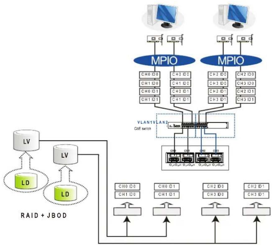
| Component Description | |
| Storage system Single-controller with 4 host ports | |
| HBA or NIC | iSCSI initiators, preferably PCIe TOE (TCP/IP offload engine)-capable cards |
| GbE cables GbE network cables | |
| Software | MPIO to manage the fault-tolerant paths with failover/failback and load balance capabilities. |
| RAID configuration | Four logical partitions (created from two logical volumes)Two logical volumes (each contains a logical drive)Two logical drives |
| NOTE: Each logical partition appears on two different host links for fault tolerance. Use MPIO software so that your operating system can identify the alternate paths to the same logical drive. | |
High Availability IP SAN (Recommended for remote replication)
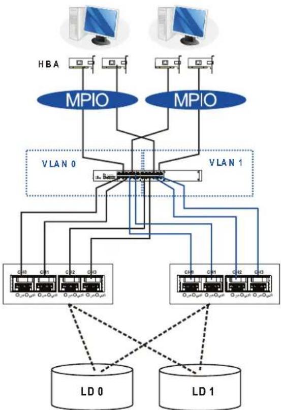
flowchart
graph TD
    subgraph VLAN 0
        HBA["HBA"] --> MPIO1["MPIO"]
        MPIO1 --> VLAN1["VLAN 1"]
    end
    subgraph VLAN 1
        MPIO2["MPIO"] --> VLAN1
    end
    HBA -.-> LD0["LD 0"]
    LD0 -.-> LD1["LD 1"]
    style HBA fill:#f9f,stroke:#333
    style MPIO1 fill:#bbf,stroke:#333
    style MPIO2 fill:#bbf,stroke:#333
    style LD0 fill:#dfd,stroke:#333
    style LD1 fill:#dfd,stroke:#333
CH 0 AID* CH1 B ID*
CH 1 BID CH0 A ID
CH2 A ID ^ CH3 B ID ^
CH3 B ID CH2 A ID
| Component Description | |
| Storage system Redundant controllers with eight host ports | |
| HBA | iSCSI initiators, preferably PCIe TOE (TCP/IP offload engine)-capable cards |
| GbE cables GbE network cables | |
| GbE switch | Ports divided into 2 virtual LANs. Both controllers are linked to both virtual LAN zones. |
| Software | MPIO to manage the fault-tolerant paths with failover/failback and load balance capabilities. Use MPIO multipathing software for the operating system to identify the alternative paths to the same logical drive. |
| RAID configuration | Two logical drives; each has eight member drives. You can create more logical drives from the drives in the expansion systems.LD0 mapped to CH0 AID, CH1 BID, CH2 AID, and CH3 BID.LD must be assigned to controllers A and B to enable remote replication.LD1 mapped to CH1 BID, CH0 AID, CH3 BID, and CH2 AID.LD must be assigned to controllers A and B to enable remote replication. |
IMPORTANT! For systems operating in Windows® 2003 server, and in the event of single-controller failure, a logical drive drive is accessed via the host IDs managed by the alternate controller. The host and port IDs do not failover to the remaining controller. In this case, MPIO driver is necessary for path redundancy and controller failover.
High Availability IP SAN with Port Trunk (Remote replication-enabled)
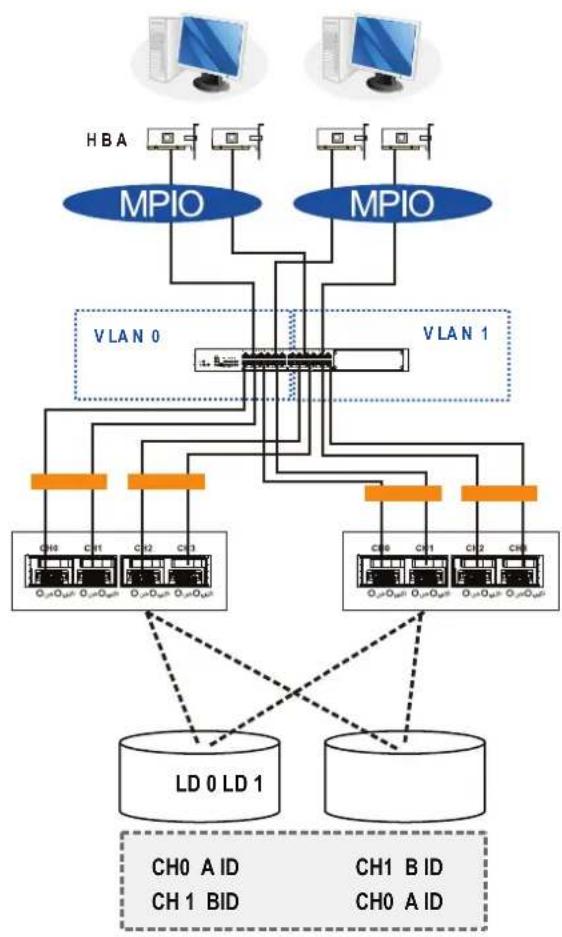
flowchart
graph TD
    subgraph VLAN 0
        A["Ch0"] --> B["CL1"]
        C["Ch1"] --> D["CL2"]
        E["Ch3"] --> F["CL3"]
        G["Ch4"] --> H["CL4"]
        I["Ch5"] --> J["CL5"]
        K["Ch6"] --> L["CL6"]
    end
    subgraph VLAN 1
        M["Ch0 A ID"] --> N["LD 0 LD 1"]
        O["CH1 B ID"] --> P["LD 0 LD 1"]
        Q["CH0 A ID"] --> R["LD 0 LD 1"]
    end
    H --> M
    H --> O
    H --> P
    H --> R
    style VLAN 0 fill:#f9f,stroke:#333
    style VLAN 1 fill:#ccf,stroke:#333
    style VLAN 0 fill:#cfc,stroke:#333
    style VLAN 1 fill:#fcc,stroke:#333
| Component Description | |
| Storage system Redundant controllers with eight host ports | |
| HBA | iSCSI initiators, preferably PCIe TOE (TCP/IP offload engine)-capable cards |
| GbE cables GbE network cables; port trunking marked in orange rectangles | |
| GbE switch | Ports divided into 2 virtual LANs. Both controllers are linked to both virtual LAN zones. |
| Software | MPIO to manage the fault-tolerant paths with failover/failback and load balance capabilities. Use MPIO multipathing software for the operating system to identify the alternative paths to the same logical drive. |
(see next page)
Component Description
RAID configuration
- Two logical drives; each has eight member drives. You can create more logical drives from the drives in the expansion systems.
- LD0 mapped to CH0 AID, CH1 BID. LD must be assigned to controllers A and B to enable remote replication.
- LD1 mapped to CH1 BID, CH0 AID. LD must be assigned to controllers A and B to enable remote replication.
2.3.5 Hybrid host connections
For hybrid systems that feature two additional iSCSI ports, you can use these systems for remote replication or for host LUN mapping.
Single Hybrid Unit Connected to FC/iSCSI Hosts
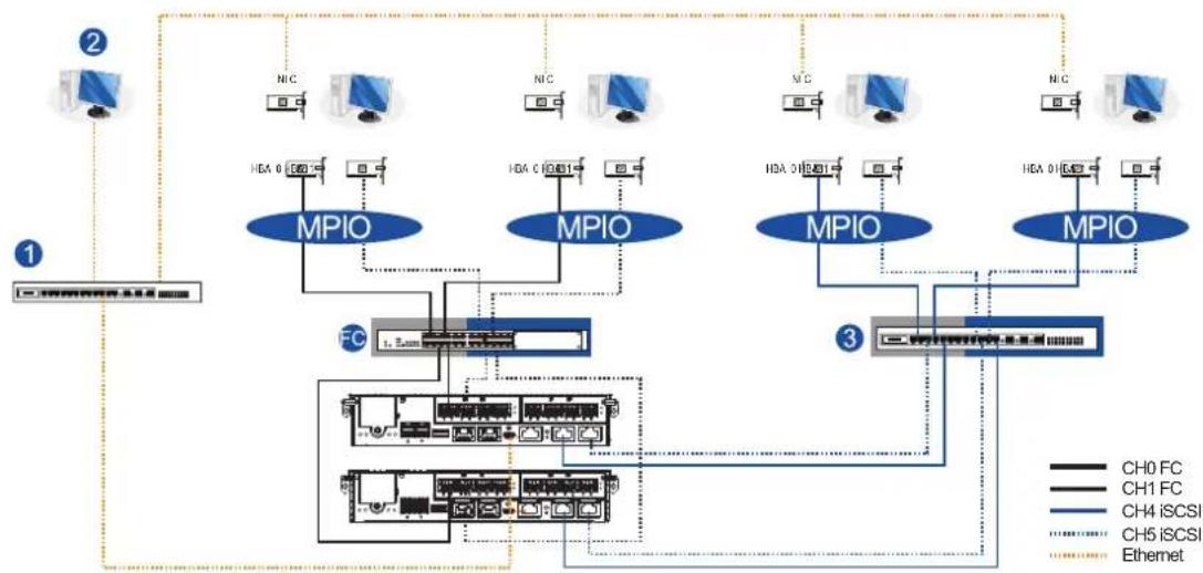
flowchart
graph TD
    subgraph Channel 1
        A["CH0 FC"] --> B["MPIO"]
        C["CH1 FC"] --> B
        D["CH4 iSCSI"] --> E["MPIO"]
        F["CH5 iSCSI"] --> E
        G["Ethermet"] --> H["Network Interface"]
    end

    subgraph Channel 2
        I["NIC"] --> J["MPIO"]
        K["NIC"] --> L["MPIO"]
        M["NIC"] --> N["MPIO"]
        O["NIC"] --> P["MPIO"]
        Q["NIC"] --> R["MPIO"]
        S["NIC"] --> T["MPIO"]
    end

    subgraph Channel 3
        U["CH0 FC"] --> V["MPIO"]
        W["CH1 FC"] --> V
        X["CH4 iSCSI"] --> Y["MPIO"]
        Z["CH5 iSCSI"] --> Y
        AA["Ethermet"] --> AB["Network Interface"]
    end

    style Channel 1 fill:#f9f,stroke:#333
    style Channel 2 fill:#bbf,stroke:#333
    style Channel 3 fill:#bfb,stroke:#333
When connected to FC and iSCSI hosts, the connections are working in their respective speeds. This connection maximizes the number of connections while keeping the optimum performance gained by the high-speed FC link and FC switch.
NOTES:
- To gain optimum performance, ensure that the LAN switch (1) for the management station (2), the LAN switch for the systems, and the iSCSI switch (3) for iSCSI host link are separated.
- If they are not separated, the host may consider that the iSCSI connection is a part of the host connection and might use it for data I/O, even if the iSCSI ports are not mapped to the host. As a result, the data transaction speed slows down to iSCSI connection's level and the fast FC connection bandwidth may be spent without use.
Utilizing Hybrid iSCSI ports for data replication
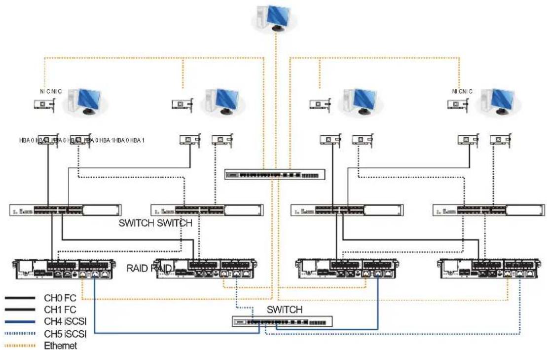
flowchart
graph TD
    A["Switch"] --> B["Switch Switch"]
    B --> C["RAID RAID"]
    B --> D["NI CNIC"]
    B --> E["NI CNIC"]
    B --> F["NI CNIC"]
    B --> G["NI CNIC"]
    B --> H["NI CNIC"]
    B --> I["NI CNIC"]
    B --> J["NI CNIC"]
    B --> K["NI CNIC"]
    B --> L["NI CNIC"]
    B --> M["NI CNIC"]
    B --> N["NI CNIC"]
    B --> O["NI CNIC"]
    B --> P["NI CNIC"]
    B --> Q["NI CNIC"]
    B --> R["NI CNIC"]
    B --> S["NI CNIC"]
    B --> T["NI CNIC"]
    B --> U["NI CNIC"]
    B --> V["NI CNIC"]
    B --> W["NI CNIC"]
    B --> X["NI CNIC"]
    B --> Y["NI CNIC"]
    B --> Z["NI CNIC"]
    B --> AA["NI CNIC"]
    B --> AB["NI CNIC"]
    B --> AC["NI CNIC"]
    B --> AD["NI CNIC"]
    B --> AE["NI CNIC"]
    B --> AF["NI CNIC"]
    B --> AG["NI CNIC"]
    B --> AH["NI CNIC"]
    B --> AI["NI CNIC"]
    B --> AJ["NI CNIC"]
    B --> AK["NI CNIC"]
    B --> AL["NI CNIC"]
    B --> AM["NI CNIC"]
    B --> AN["NI CNIC"]
    B --> AO["NI CNIC"]
    B --> AP["NI CNIC"]
    B --> AQ["NI CNIC"]
    B --> AR["NI CNIC"]
    B --> AS["NI CNIC"]
    B --> AT["NI CNIC"]
    B --> AU["NI CNIC"]
    B --> AV["NI CNIC"]
    B --> AW["NI CNIC"]
    B --> AX["NI CNIC"]
    B --> AY["NI CNIC"]
    B --> AZ["NI CNIC"]
    B --> BA["NI CNIC"]
    B --> BB["NI CNIC"]
    B --> BC["NI CNIC"]
    B --> BD["NI CNIC"]
    B --> BE["NI CNIC"]
    B --> BF["NI CNIC"]
    B --> BG["NI CNIC"]
    B --> BH["NI CNIC"]
    B --> BI["NI CNIC"]
    B --> BJ["NI CNIC"]
    B --> BK["NI CNIC"]
    B --> BL["NI CNIC"]
    B --> BM["NI CNIC"]
    B --> BN["NI CNIC"]
    B --> BO["NI CNIC"]
    B --> BP["NI CNIC"]
    B --> BQ["NI CNIC"]
    B --> BR["NI CNIC"]
    B --> BS["NI CNIC"]
    B --> BT["NI CNIC"]
    B --> BU["NI CNIC"]
    B --> BV["NI CNIC"]
    B --> BW["NI CNIC"]
    B --> BX["NI CNIC"]
    B --> BY["NI CNIC"]
    B --> BZ["NI CNIC"]
    B --> CA["NI CNIC"]
    B --> CB["NI CNIC"]
    B --> CC["NI CNIC"]
    B --> CD["NI CNIC"]
    B --> CE["NI CNIC"]
    B --> CF["NI CNIC"]
    B --> CG["NI CNIC"]
    B --> CH["NI CNIC"]
    B --> CI["NI CNIC"]
    B --> CJ["NI CNIC"]
    B --> CK["NI CNIC"]
    B --> CL["NI CNIC"]
    B --> CM["NI CNIC"]
    B --> CN["NI CNIC"]
    B --> CO["NI CNIC"]
    B --> CP["NI CNIC"]
    B --> CQ["NI CNIC"]
    B --> CR["NI CNIC"]
    B --> CS["NI CNIC"]
    B --> CT["NI CNIC"]
    B --> CU["NI CNIC"]
    B --> CV["NI CNIC"]
    B --> CW["NI CNIC"]
    B --> CX["NI CNIC"]
    B --> CY["NI CNIC"]
    B --> CZ["NI CNIC"]
    B --> DA["NI CNIC"]
    B --> DB["NI CNIC"]
    B --> DC["NI CNIC"]
    B --> DD["NI CNIC"]
    B --> DE["NI CNIC"]
    B --> DF["NI CNIC"]
    B --> DG["NI CNIC"]
    B --> DH["NI CNIC"]
    B --> DI["NI CNIC"]
    B --> DJ["NI CNIC"]
    B --> DK["NI CNIC"]
    B --> DL["NI CNIC"]
    B --> DV["NI CNIC"]
    B --> DW["NI CNIC"]
    B --> DX["NI CNIC"]
    B --> DXB["NI CNIC"]
The illustration above depicts the utilization of the iSCSI host ports for remote data replication. This type of connection allows you to get the full benefits of high-speed FC host link, management LAN connection, and robust link for data protection (volume copy/mirror).
Two hybrid systems, a source system and a target system, reside within the same virtual pool but are physically apart. You can create a volume copy/mirror pair for data protection without relying on slow management LAN cable connections. In such case, you can link the hybrid systems using iSCSI host ports. If the distances between systems are far, additional switches may be required.
Use EonOne to configure the volume copy/mirror settings. EonOne automatically detects the iSCSI data connection for data replication.
2.3.6 Expansion connections
When expanding your system, you can add expansion (JBOD) systems and connect between devices via the SAS ports or the added SAS 12 G host board.
A SAS host link cable is bundled per expansion package. If you need to purchase other cables, or if you need other cables of different lengths, contact your vendor.
Before configuring the expansions, you must take note of the following important points:
- For a cleaner and clutter-free rack system, have a carefully planned routing paths when connecting between systems.
- All SAS cables are sensitive and must be handled with care. DO NOT bend or twist the cables when connecting the systems installed to the rack.
Configuring the SAS expansion
The SAS expansion port of the GSa system connects to the expansion systems. For dual-controller systems, each expansion port connects to a controller of another expansion system, making a fault-tolerant linkage to different SAS domains.
The following principles apply to main storage and expansion system connections:
- Dual-controller main storage connects to a single-controller expansion system
- Single-controller main storage connects to a single-controller expansion system
- A longer cable is available in making expansion links with a dual-controller configuration. If you need to connect expansion systems from two opposite directions, you may need a longer cable. Routing between two different connections can avoid loss of data links if one expansion fails to operate.
Setting the expansion IDs
Each expansion system must have a unique ID and you can configure the ID via the rotary ID switch. To set the expansion IDs, use a small flat-blade screwdriver.
You must take note of the following when setting the IDs on the expansion system:
- Set the IDs from 1 to 15. The order starts from the expansion enclosure that is closest to the managing GSa enclosure.
- Ensure to set a unique ID on each expansion enclosure so that the SAS WWN addresses of the disk drives are properly assigned. The storage system firmware automatically manages these addresses.
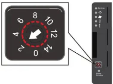
text_image
8 10 9 12 4 2 14 0Configuration rules
To connect the SAS interfaces across storage and expansion systems, you must take note of the following:
- Fault-tolerant links in a dual-controller combination
Corresponding to the dual-port interfaces of the SAS drives, two physical links are available per disk drive, routed across the backplane board, then to a SAS expander, and interfaced via a 4x wide external SAS port.
- With data paths via separate SAS domains
Access to disk drives can be continued in the event of a failure from a cable link or SAS expansion controller.
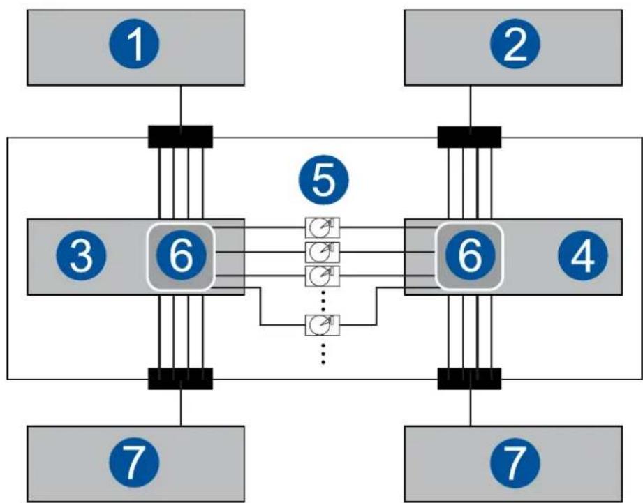
flowchart
graph TD
    A["1"] --> B["6"]
    C["2"] --> D["6"]
    E["3"] --> F["6"]
    G["4"] --> H["6"]
    I["5"] --> J["6"]
    K["7"] --> L["6"]
    M["7"] --> N["6"]
    style A fill:#ccc
    style C fill:#ccc
    style E fill:#ccc
    style G fill:#ccc
    style I fill:#ccc
    style K fill:#ccc
    style M fill:#ccc
    style N fill:#ccc
| Number Description | |
| 1 | RAID controller A |
| 2 | RAID controller B |
| 3 | Expansion system controller A |
| 4 | Expansion system controller B |
| 5 | Dual-port SAS drives |
| 6 | Expander |
| 7 | To another expansion system |
- Fault-tolerant links to SAS disk drives
- The SAS expansion cables are bundled with the expansion systems. Take note that if there are many expansion systems connected, a longer SAS external cable, approximately measured 120 cm, may be needed to connect an expansion system from the opposite direction for a higher redundancy.
- One expansion link connects the expansion system from a storage system with HBA/RAID card to the nearest expansion system, then to the most distant expansion system. Another expansion link connects to the most distant expansion system, from the opposite direction to the first expansion system from the storage system.
- Each expander controller on the SAS expansion system controls a SAS domain that connects to one of the alternative interfaces of the disk drives in the enclosure. For example, one expander unit controls Domain A while the other expander controls Domain B. In a fault-tolerant topology, the SAS external links always connect to the SAS ports of the same SAS domain.
- Identify the SAS domains by the location of the expanders: the left controller is controller A, the right is controller B.
- On a storage system, each controller is considered as managing a separate SAS domain. With the help of the port selector mechanism on the MUX boards, the idea of SAS domain applies even when SATA drives are used in a dual-controller expansion system.
Connecting expansion systems
- Connecting dual-controller expansions

flowchart
graph TD
    A["STORAGE SYSTEM"] --> B["1"]
    A --> C["2"]
    A --> D["3"]
    A --> E["4"]
    A --> F["5"]
    A --> G["6"]
    H["IN IN"] --> A
    I["IN OUT"] --> A
    J["EXPANSION"] --> A
    K["EXPANSION"] --> B
    L["EXPANSION"] --> C
    M["EXPANSION"] --> D
    N["EXPANSION"] --> E
    O["EXPANSION"] --> F
    P["EXPANSION"] --> G
    Q["EXPANSION"] --> R
    S["EXPANSION"] --> T
    U["EXPANSION"] --> V
    W["EXPANSION"] --> X
    Y["EXPANSION"] --> Z
    AA["EXPANSION"] --> AB
    AC["EXPANSION"] --> AD
    AE["EXPANSION"] --> AF
    AG["EXPANSION"] --> AH
    AI["EXPANSION"] --> AJ
    AK["EXPANSION"] --> AL
    AM["EXPANSION"] --> AN
    AO["EXPANSION"] --> AP
    AQ["EXPANSION"] --> AR
    AS["EXPANSION"] --> AT
    AU["EXPANSION"] --> AV
    AW["EXPANSION"] --> AX
    AY["IN IN"] --> A
    AZ["A"] --> BA["B"]
    BB["A"] --> BC["B"]
    BD["A"] --> BE["B"]
    BF["A"] --> BG["B"]
    BH["A"] --> BI["B"]
    BJ["A"] --> BK["B"]
    BL["A"] --> BM["B"]
    BN["A"] --> BO["B"]
    BP["A"] --> BQ["B"]
    BR["A"] --> BS["B"]
    BT["A"] --> BU["B"]
    BV["A"] --> BW["B"]
    BX["A"] --> BY["B"]
    BZ["A"] --> BQ["B"]
    BNB["A"] --> BN["B"]
    BOB["A"] --> BO["B"]
    BXB["A"] --> BXB["B"]
    BYBB["A"] --> BYBB["B"]
- Storage controller : left SAS port IN Expansion
- Expansion 1, controller ASAS port IN Expansion
- Expansion 3, controller ASAS port IN Expansion
- Storage controller : right SAS port IN Expansion
- Expansion 2, controller ASAS port IN Expansion
- Expansion 4, controller ASAS port IN Expansion
- Storage controller : left SAS port IN Expansion
- Expansion 5, controller B SAS port IN Expansion
- Expansion 3, controller ESAS port IN Expansion
- Storage controller : right SAS port IN Expansion
- Expansion 6 or last, controller PSAS port IN Expansion
- Expansion 4, controller ESAS port IN Expansion
1, controller ASAS port OUT
③, controller ASAS port OUT
5, controller ASAS port OUT
②, controller /SAS port OUT
4, controller ASAS port OUT
6 or last, controller AsAS port OUT
⑤ or last, controller B SAS port OUT
③, controller : SAS port OUT
1, controller B SAS port OUT
6 or last, controller : SAS port OUT
4, controller BSAS port OUT
②, controller B SAS port OUT
- Connecting double-controller expansions using the host board's SAS expansion ports
STORAGE SYSTEM
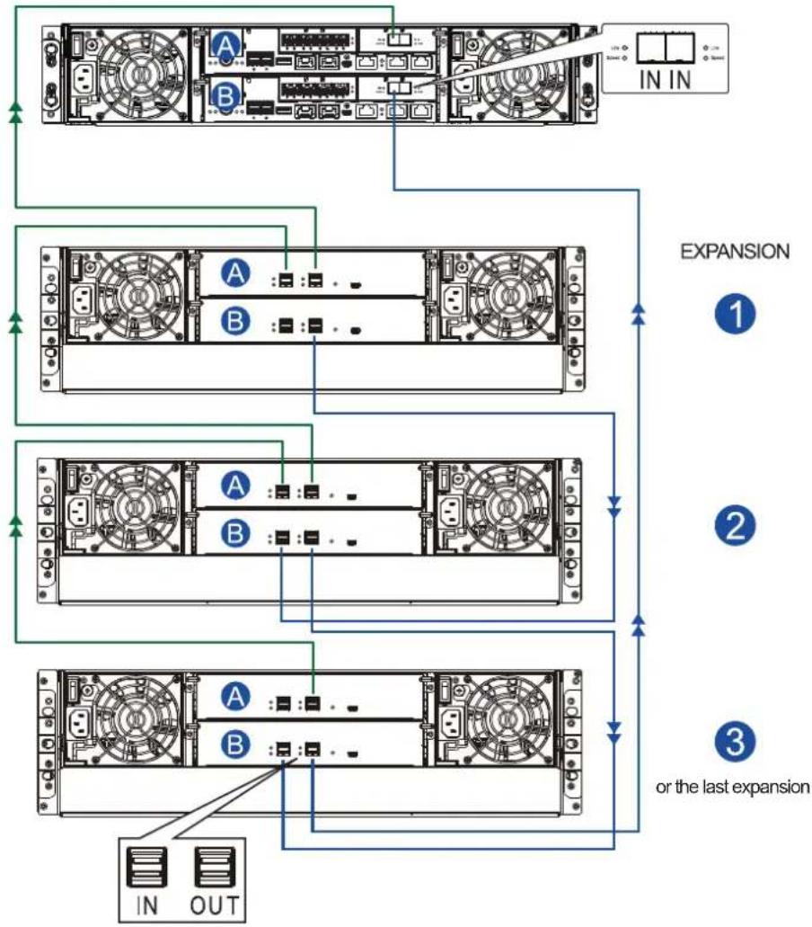
flowchart
graph TD
    A["Server Rack"] --> B["Component A"]
    A --> C["Component B"]
    D["Input"] --> E["In/Out"]
    F["Expansion"] --> G["①"]
    F --> H["②"]
    F --> I["③"]
    style A fill:#f9f,stroke:#333
    style B fill:#ccf,stroke:#333
    style C fill:#cfc,stroke:#333
    style D fill:#fcc,stroke:#333
    style E fill:#ffc,stroke:#333
    style F fill:#fcc,stroke:#333
    style G fill:#fff,stroke:#333
    style H fill:#fff,stroke:#333
    style I fill:#fff,stroke:#333
- Storage controller : host board SAS port IN Expansion
- Expansion 1, controller ASAS port IN Expansion
- Expansion ②, controller ASAS port IN Expansion
- Storage controller : host board SAS port IN Expansion OUT
- Expansion ③ or last, controller P8AS port IN Expansion
- Expansion 2, controller B/SAS port IN Expansion
1, controller ASAS port OUT
②, controller ASAS port OUT
③ or last, controller ASAS port OUT
③ or last, controller : SAS port
2, controller B SAS port OUT
1, controller B SAS port OUT
- Connecting single-controller expansions using the onboard SAS expansion ports
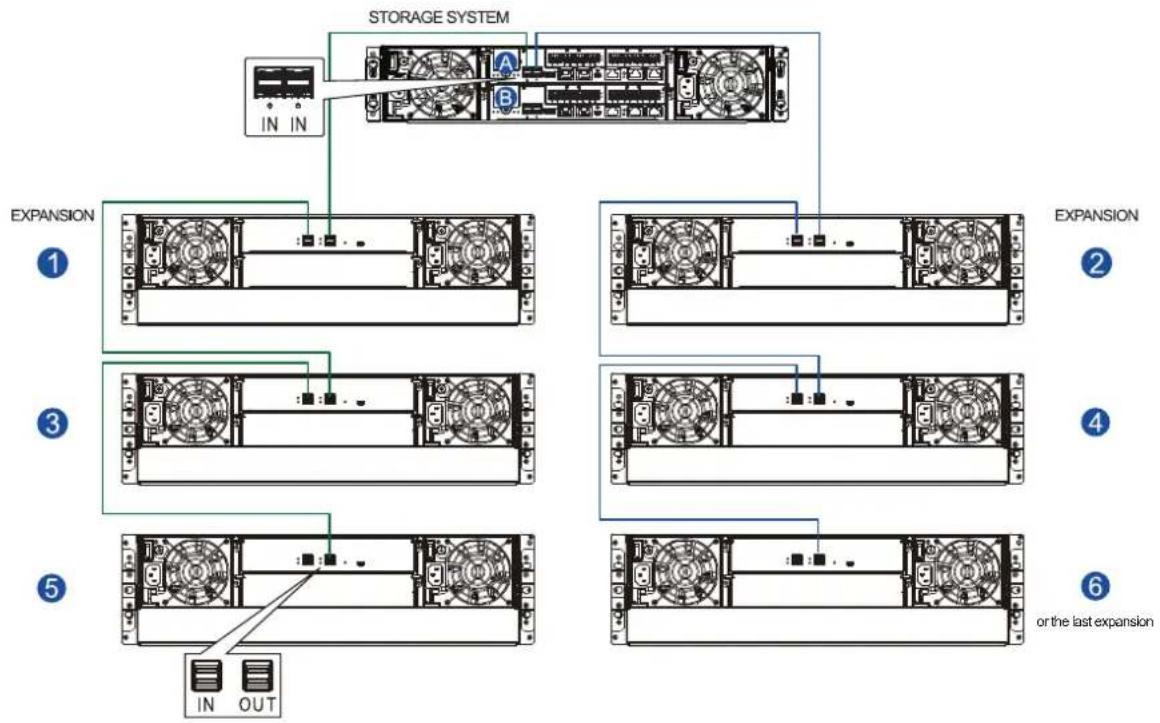
flowchart
graph TD
    A["IN IN"] --> B["STORAGE SYSTEM"]
    B --> C["EXPANSION ①"]
    B --> D["EXPANSION ②"]
    B --> E["EXPANSION ③"]
    B --> F["EXPANSION ④"]
    B --> G["EXPANSION ⑤"]
    B --> H["EXPANSION ⑥"]
    style A fill:#f9f,stroke:#333
    style B fill:#ccf,stroke:#333
    style C fill:#cfc,stroke:#333
    style D fill:#cfc,stroke:#333
    style E fill:#cfc,stroke:#333
    style F fill:#cfc,stroke:#333
    style G fill:#cfc,stroke:#333
    style H fill:#cfc,stroke:#333
• Storage controller: left SAS port IN Expansion 1: SAS port OUT
- Expansion ①: SAS port IN Expansion ③: SAS port OUT
- Expansion ③: SAS port IN → Expansion ⑤: SAS port OUT
• Storage controller: right SAS port IN Expansion ②: SAS port OUT
• Expansion ②: SAS port IN • Expansion ④: SAS port OUT
- Expansion ④: SAS port IN Expansion ⑥ or last: SAS port OUT
- Connecting single-controller expansions using the host board's SAS expansion ports STORAGE SYSTEM

flowchart
graph TD
    A["In In"] --> B["Expansion"]
    B --> C["1"]
    B --> D["2"]
    B --> E["3"]
    B --> F["4"]
    B --> G["5"]
    B --> H["6"]
    H --> I["or the last expansion"]
    I --> J["IN OUT"]
2.3.7 Management console connections
To connect you main storage to external consoles, you need the following:
• DB 9 female to mini-USB cable (bundled with the package)
• CAT 5e LAN cable (user supplied)
Connecting main storage to external consoles

flowchart
graph TD
    A["RS-232 Management console"] --> B["EonOne/Telnet console"]
    B --> C["LAN"]
    C --> D["DB 9 female to mini-USB cable"]
    C --> E["CAT 5E LAN cable"]
    style A fill:#f9f,stroke:#333
    style B fill:#ccf,stroke:#333
    style C fill:#cff,stroke:#333
    style D fill:#ffc,stroke:#333
    style E fill:#cfc,stroke:#333
IMPORTANT! Always connect to the primary controller.
NOTES:
- A null modem may be required if you are using a third-party cable.
- For TCP/IP connection and firewall configuration, refer to EonOne, your management software's online help, or user manual. If your network is not running the DHCP server protocols, you can use the default IP 10.10.1.1 if you are accessing for the first time.
2.3.8 Power connection
Before connecting to a power source, ensure that all components are properly installed and the management interfaces are properly connected.
Take a look at the list below and check the following:
- The hard drives are correctly installed to the drive trays.
- All drive trays are installed to the system, whether or not they contain a hard drive.
- The system is connected to host computers, management computers, or external networking devices with the correct cables.
IMPORTANT! Ensure to use the power cables with at least 1.2 meters in length. DO NOT use extension cables as the power cables are designed to connect ONLY and DIRECTLY to relocatable power taps (RPTs) on server cabinets.
- Ensure that the ambient temperature is not less than 35^ C (with CBM).
Connecting to power source
Use the bundled power cables and connect them to the power sockets for both PSUs.

natural_image
Top-down schematic of a computer drive bay showing front, rear, and side views with ports and connectors (no text or labels)Turning on the system
Before turning on the GSa system, you must turn on the expansion enclosures first if your network configuration consists of multiple arrays.
To turn on the system:
- Turn on the networking devices.
- Turn on the JBOD expansion systems.
- Press the power switches located at the PSUs, from left to right order.

natural_image
Back view of a server rack with two ports, showing internal components and ventilation slots (no text or labels visible)- Turn on the application servers.
Checking the power status
Once the system is on, no LEDs should light up in red or amber, nor should you hear an alarm from the system. Start verifying the system status via the following interfaces:
- Front panel LEDs
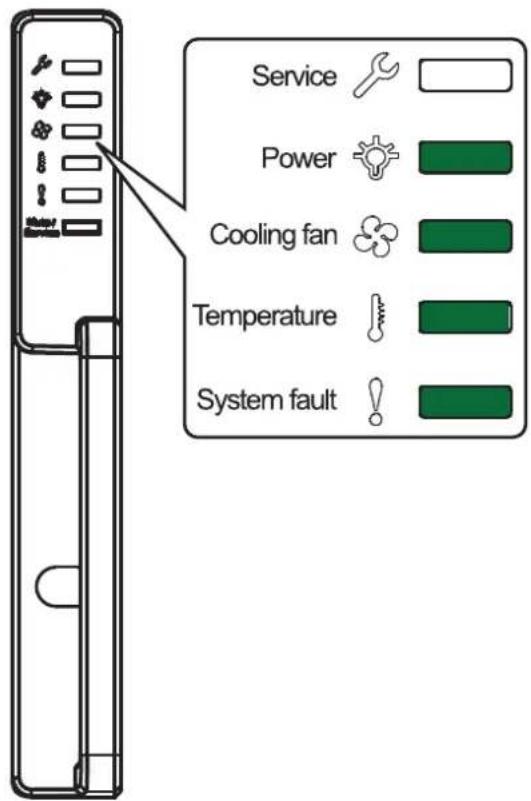
text_image
Service Power Cooling fan Temperature System fault- Controller module LEDs
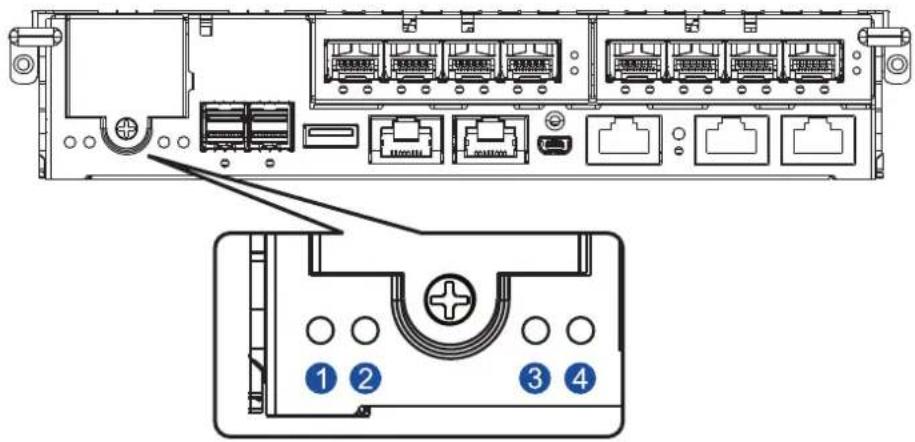
text_image
Diagram of a server rack with labeled ports and connectors, showing internal structure and component labels 1, 2, 3, 4.| Number Name Status | |
| 1 | Cache Dirty OFF |
| 2 | Host Busy OFF |
| 3 | Control Status ON |
| 4 | CBM Status ON |
NOTE: Refer to chapter System maintenance for more information regarding the LED description.
- PSU LED
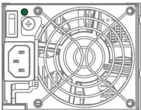
natural_image
Technical line drawing of a computer fan assembly with circuitry and mounting points (no text or symbols)2.3.9 Turning off the system
Before turning off the system, ensure that no processes are taking place such as Regenerate Logical Drive Parity or Media Scan.
To turn off the system:
- Close all applications to stop the I/O access to the system.
- Flush the cache to clear the DRAM data. If the DRAM contains cached data, the Cache_Dirty LED lights up in amber.
- Flush all cached data using the controller's shutdown function to prepare the RAID system for a safe power shutdown. Refer to EonOne manual for details.
- Once the cache is flushed, switch off the system.
System monitoring
3
This chapter details the monitoring features and the status of EonStor GSa 3000 Series.
3.1 Monitoring features
The EonStor GSa 3000 Series is equipped with self-monitoring features the help you keep track of the system's operating status.
You can monitor your system's status with the following features:
- Firmware
The firmware manages the controllers of the system, which is accessible in a terminal program via the serial port. For more details, see the firmware manual in the bundled CD.
- EonOne
EonOne is a browser-based GUI (graphic user interface) software that you can install into a local or remote computer and access via the network. You can refer to EonOne manual in your bundled CD for more information.
• LEDs
The LEDs are indicators that notify you of the system status, events, and errors or failed operations. The LEDs are located on both front and rear panels of the chassis.
- Audible alarms
The audible alarms are triggered in case of system failures. For more information, see PSU LED.
3.1.1 LEDs
This section details the system LEDs and their descriptions.
Front panel LEDs
| Service | OFF | The system is being serviced or is requiring services. |
| The system is not being serviced or does not require a service. | ||
| Power | The system is powered properly. | |
| A power failure occurred in the system. | ||
| Cooling fan status | The cooling fan built with the PSU are running normally. | |
| A fan failure occurred. | ||
| Temperature status | The internal temperature is normal and within the safety threshold. | |
| The internal temperature exceeds the safety threshold. | ||
| System fault | The system is operating normally. | |
| The system encounters abnormal conditions. |
IMPORTANT! If the cooling fan status lights up in, check the fan built with the PSU.
- Drive tray LEDs
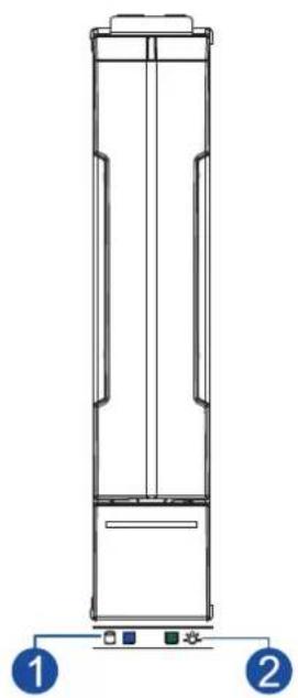
natural_image
Technical line drawing of a vertical cylindrical device with two labeled components (1 and 2), no text or symbols present.There are two LEDs on the tray that indicate the status of your drives. When you get notified by a drive failure message, you must check the drive tray LEDs to find the correct location of the failed drive.
| Number LED name Color Description | ||
| 1 | Drive Busy | |
| The hard drive is plugged in but there is no activity going on. | ||
| 2 | Power status | |
| The drive bay is occupied and working normally. | ||
| Disk drive failed or connection problem occurred. | ||
Rear panel LEDs
- Controller LEDs
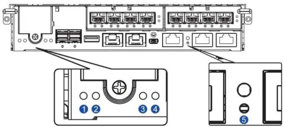
text_image
Diagram of a server rack with labeled ports and internal components, showing numbered labels for identification.| Number LED name Color Description | ||
| 1 | Control Status | A controller is operating normally. |
| A component has failed or inappropriate RAID configurations caused system faults.The controller is initializing. | ||
| 2 | CBM Status | Both supercapacitor and flash modules are installed in the system.The CBM is ready for operation.The CBM failed in operating, either the supercapacitor or flash module.Either the supercapacitor or the flash module is missing. |
| The supercapacitor is charging. | ||
| 3 | Cache Dirty | Cache memory is dirty.Data in flash backup module is flushed to the cache.Errors occurred with cache memory (ECC errors).Data is flushed from flash backup module to drive when the power is restored.The supercapacitor temperature reading is abnormal (out of 0 - 35°C range).The supercapacitor is not present. |
| The cached data is being transferred to the flash module after a power outage. Once the transfer is done, all LEDs will turn off. This signal is local to each controller. | ||
| The cache is clean and the supercapacitor can sustain the memory in case of power loss. | ||
| 4 | Host Busy Traffic going on the host bus. | |
| 5 | Restore Default | Successfully reset the controller after the press and hold the Restore Default button. |
• 1 G Ethernet management port LEDs
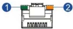
| Number LED name Status Description | |
| 1 Speed | ON 1 Gb connection is established. |
| • 10/100 Mb connection is established.OFF • No connection is established. | |
| 2 Link/Active | ON A connection is established. |
| Flashing Data I/O is ongoing. | |
| OFF No connection is established. | |
• 12 G SAS expansion port LED

0
| LED name Status Description | ||
| Link/Active | ON All 4 PHY links are validly linked. | |
| Flashing | Less than 4 PHY links are connected (at least one of the PHYs has failed). | |
| OFF All 4 PHY links are offline. | ||
• 10 G Ethernet port LEDs
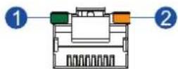
| Number LED name Color/ | Description | |
| Status | ||
| 1 | Speed | 10 Gb connection is established. |
| 1 Gb connection is established. | ||
| OFF 10/100 Mb connection is established. | ||
| 2 | Link/Active | ON A connection is established. |
| Flashing Data I/O is ongoing. | ||
| OFF No connection is established. | ||
• 16 G Fibre channel port LEDs
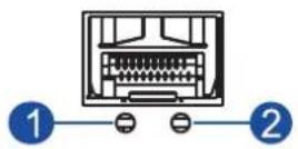
| Number LED name Color/ | Description | |
| Status | ||
| 1 | Link/Active | ON A connection is established. |
| Flashing Data I/O is ongoing. | ||
| OFF No connection is established. | ||
| 2 | Speed | 16 Gb connection is established. |
| 8 Gb connection is established. | ||
| OFF 4 Gb or slower connection is established. | ||
• 8 G Fibre channel port LEDs
These ports, if your system has them, deliver fast I/O performance for SAN applications. You can use optical cables for long distances, which proved to be reliable for this kind of setup.
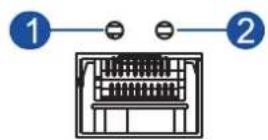
| Number LED name Color/ | Description | |
| Status | ||
| 1 | Link/Active | ON A connection is established. |
| OFF A link is broken. | ||
| 2 | Speed | 8 Gb connection is established. |
| 4 Gb connection is established. | ||
| OFF No connection is established. | ||
NOTE: For higher and speedier transfer rates, we suggest you to use optical cables for 4/8 Gb fiber connectivity. These cables are not susceptible to EMI (electromagnetic interference).
• Converged host board LEDs
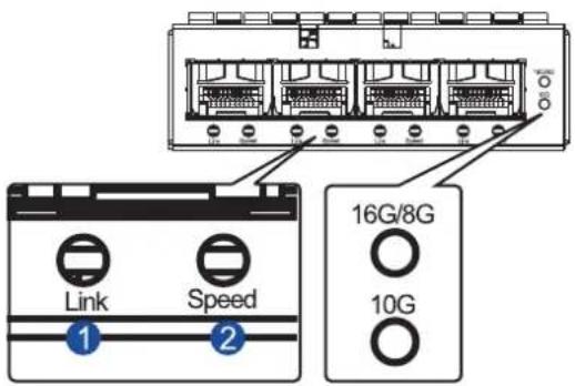
text_image
16G/8G 10G Link Speed| Number LED name Color/ | Description | |||
| Status | ||||
| 1 | Link | ● | A connection is established. | |
| OFF A link is broken. | ||||
| 2 | Speed | Color/ Status | 16 G Fibre channel | 8 G Fibre channel |
| ● | 16 G FC 8 G FC | 10 G Ethernet | ||
| ● | 8 G FC 4 G FC | |||
| OFF | 4 G FC or no link | No link No link | ||
| LED name | Connection type | Color/ Status | Description |
| 16 G/8 G | Fibre channel | 16 G Fiber channel mode | |
| 8 G Fiber channel mode | |||
| 10 G Ethernet 10 G Ethernet mode | |||
• 12 G SAS expansion controller LEDs
IN OUT
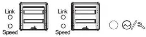
text_image
Link Speed Link Speed ○ √/2JB 3000 series
IN OUT 1 OUT 2
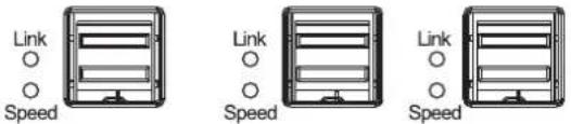
text_image
Link Speed Link Speed Link SpeedJB 3060L series
IN OUT

text_image
Link Speed Link Speed Link Speed Link SpeedJB 3060L series (drawer type)
| LED name Status Description | |
| Link/Active | ON All PHYs are validly linked. |
| Flashing One of the PHYs has failed. | |
| OFF All PHYs are offline. | |
| Speed | 12 Gb link speed |
| 6 Gb/3 Gb link speed | |
| OFF No connection | |
| The controller is operating normally. | |
| A component failure occurred.Initialization is ongoing. | |
- PSU LED
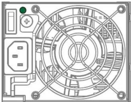
natural_image
Technical line drawing of a circular fan or fan assembly with internal components (no text or symbols)Color Description
| The system is connected to the power source but the system is not turned on. | |
| The PSU is operating normally. | |
| The PSU is faulty. |
The PSU LED alerts you of the current status of your PSU and cooling module components. When either of the components fails, you must replace the PSU immediately.
WARNING! Keep your fingers away from moving parts of the system to prevent technical mishaps and physical injuries.
NOTE: For more details, see section 4.1.1 Replacing the PSU/cooling module.
3.1.2 Alarms and I ^2 C bus
This section details the system alarms and I²C bus.
Audible alarms
You will hear an audible alarm if any of the following components fails:
- PSU/cooling modules
- Hard disk drives
- Sensors or presence detection circuitries
If you hear an audible alarm, ensure to read the error message on the terminal or EonOne screen to determine the cause of the alarm. Take appropriate actions to solve the problem. You can turn off the alarm using the mute button on the front panel. To know more of the alarm beep patterns, see the Troubleshooting Guide included in the bundled CD.
NOTE: When the temperature exceeds the preset threshold, the controller's charger circuits stop charging. You will receive a messages that says Thermal Shutdown/Enter Sleep Mode. When the temperature falls back to normal range, the battery resumes charging.
I²C bus
The operating status of the PSU/cooling modules are collected via the I²C serial bus. If either of the modules fails, the system detects the failure and you will be notified via the same methods stated in audible alarms.
System maintenance
4
This chapter provides maintenance and replacement procedures of replaceable components of your EonStor GSa 3000 Series.
4.1 Replaceable components
Your EonStor GSa 3000 system is comprised of replaceable components:
- PSU/cooling module
- Controller module
- Memory module
• CBM - Host board
- Disk drives
WARNING!
- DO NOT remove a defective component from the system until you have the replacement on hand. Doing so may disrupt the internal airflow.
- Consult with the qualified engineers who are familiar with the system to recommend you of the component replacements.
- DO NOT use excessive force when installing a replaceable module. Forced installation of the module can damage the connector pins of the system, the module, or the internal backplane.
4.1.1 Replacing the PSU/cooling module
Replace the defective PSU/cooling module immediately, but only if you have the replacement.
WARNING! Although the system can still operate with a defective PSU/cooling module, it is not recommended to use it for an extended period of time.
NOTE: For more information, contact your system vendor.
To replace the PSU:
- Shut down the system, turn off the PSU/cooling module, then unplug the power cord.
- Loosen the thumb screw that secures the extraction handle to the chassis.
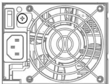
natural_image
Technical line drawing of a computer fan with circuitry and mounting points (no text or symbols)- Pull down the extraction handle to dislodge the PSU/cooling module from the backplane connectors, then gently pull the PSU/cooling module from the system. If the system is mounted to the rackmount, carefully support its weight with the rack while removing the module.
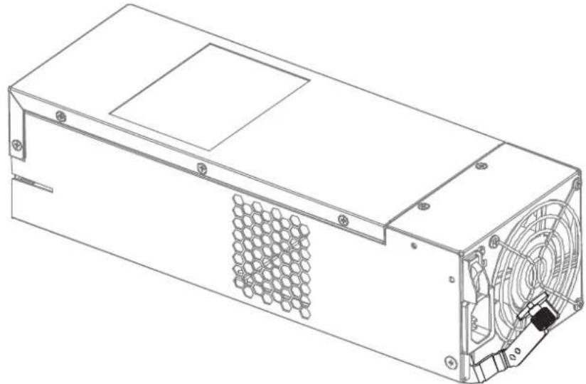
natural_image
Technical line drawing of a computer power supply unit with visible internal components and mounting holes (no text or labels)- Insert the replacement PSU/cooling module with the extraction handle pointing outwards, then push into the chassis. When you feel a resistance, push the extraction handle to lodge the PSU/cooling module to the backend connectors.
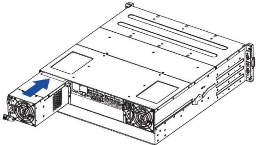
natural_image
Technical line drawing of a server rack with ventilation ducts and fan ports (no text or symbols)- Fasten the thumb screw to secure the PSU/cooling module to the system.
- Connect the power cord.
- Turn on the PSU/cooling module.
4.1.2 Replacing the controller module
In replacing a controller in a dual-controller system, ensure that the replacement controller's firmware matches with the controller that you want to get replaced. The replacement provided to you has the firmware version on the label of the packaging.
Use EonOne to find out the firmware version of the present controller. From EonOne GUI, go to Storage Manager > Information > Enclosure View.
WARNING! DO NOT use the controller modules from different models. Each module has a unique ID which is applied to the host port names. If you insist on using other models' controller modules, you may encounter SAN problems on multiple systems.
IMPORTANT! When removing/installing a controller in a single-controller system, ensure that you shut down the applications and the system.
NOTE: Refer to EonOne user manual for more details.
To replace the controller:
- From your system's software, go to Main Menu > System Functions > Shutdown controller function to stop all I/O access to the system and the cached data are distributed to the disk drives.
- Shut down the system, switch off the power buttons, and unplug the power cords from the PSUs.
-
Disconnect all cables from the controller module that you want to be replaced.
-
Loosen the screws that secure the controller module's ejection levers to the chassis.
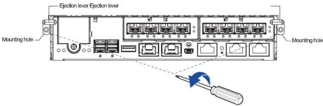
text_image
Ejection lever Ejection lever Mounting hole Mounting hole- Push down the ejection levers to dislodge the controller from the system (A), then pull to remove from the enclosure (B).
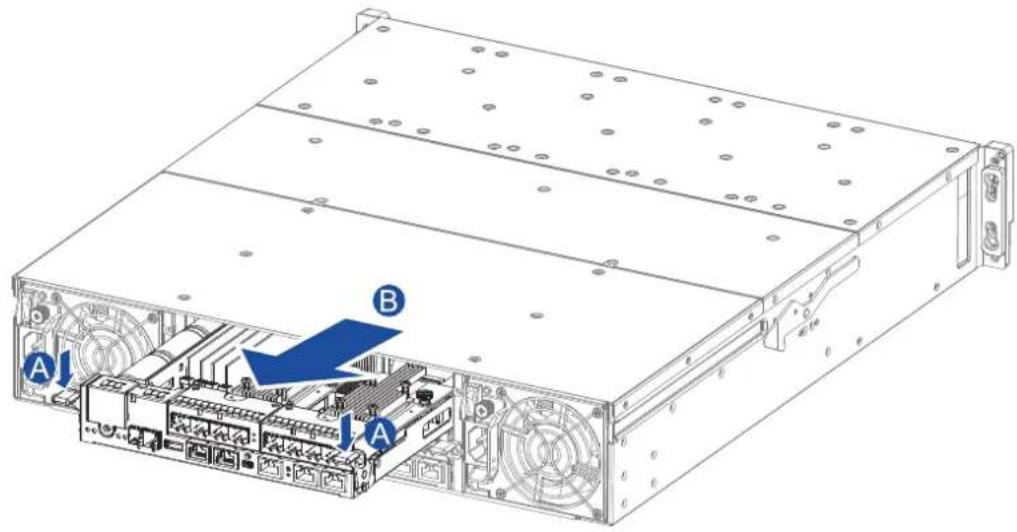
text_image
Technical diagram of a server rack with labeled components A and B, showing internal circuitry and ventilation slots.- Insert the replacement controller carefully into the controller module slot. When you feel a contact resistance, push the controller with a small but careful force, then move the ejection levers upwards to secure the controller to the enclosure.
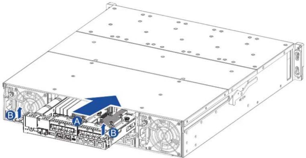
text_image
Technical diagram of a server rack with labeled components A and B, showing internal structure and ventilation slots.- To secure the controller to the chassis, fasten two retention screws to the controller's mounting holes under the ejection levers.
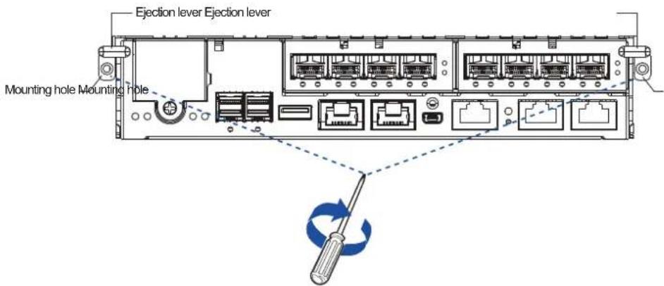
text_image
Ejection lever Ejection lever Mounting hole Mounting hole-
Reconnect the cables to the controller's ports.
-
Turn on the system then check the messages on the system's LCD panel, EonOne, or firmware utility. The power LEDs turn on when the system is successfully initiated online.
-
From your firmware, look for Restore NVRAM from Disks or Restore NVRAM from Files to restore your previous ID/LUN mapping configuration.
4.1.3 Replacing the memory module
The controller comes with a pre-installed DRAM module(s). You can upgrade or replace it when the bundled module malfunctions.
IMPORTANT!
- We strongly recommend you to NOT use the removed DRAM module from a failed controller of a different storage system.
- Contact your system vendor to help you purchase the compatible DRAM modules.
NOTE: Refer to section ESD precautions for safety information.
To replace the memory module:
- Shut down your system, unplug the power cords, then remove the controller. Wait for a minute for the remaining electric current to dissipate.
NOTE: See section 4.1.2 Replacing the controller module for details.
- Look for the DIMM slots in the controller.
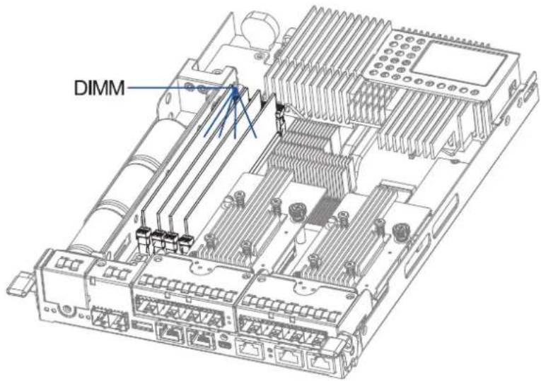
text_image
DIMM- Push down the clips to release the DRAM module from the DIMM socket.
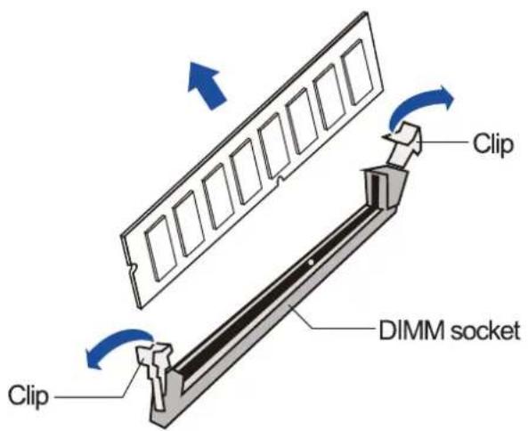
text_image
Clip Clip DIMM socket- Insert the replacement DIMM carefully into the DIMM socket, with the DIMM's notch aligned to the DIMM socket's notch guide.
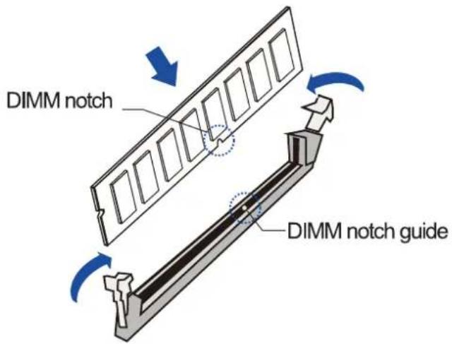
text_image
DIMM notch DIMM notch guide- Insert the controller back to the enclosure.
4.1.4 Replacing the CBM (Cache Backup Module) components
The CBM is comprised of a super capacitor and the FBM (flash backup module). The super capacitor allows your controller to provide more power during a power outage, supporting the controller to save the data to the FBM.
WARNING! Ensure that you have the replacement on hand before replacing your current CBM.
Super capacitor fault conditions and precautions
If a super capacitor leaks, gives off bad odor, generates heat, becomes discolored or deformed, or appears abnormal when charging or storing, remove it from the system immediately. These issues may be due to the following:
- The temperature sensor on the system's charger circuit reports the temperature that exceeds the preset threshold. The charger circuit enters to a low power and self-protection state.
- A super capacitor module has been charged for more than 10 minutes. When this occurs, the charger enters a timer fault state. Charging resumes automatically after you remove or reinstall the super capacitor, or after you reset the system.
When reinstalling/replacing the super capacitor, remember these precautions:
- ONLY use a replacement super capacitor supplied by an authorized distributor. Use of other capacitors voids your system's warranty.
- ONLY dispose your used/defective super capacitor at an authorized battery disposal sites.
- DO NOT place the super capacitor near a heat source.
- DO NOT immerse/submerge the super capacitor in water or other liquids.
- DO NOT disassemble or modify the super capacitor.
- DO NOT pierce, strike, throw, or exert pressure on the super capacitor.
Replacing the super capacitor
To replace the super capacitor:
- Shut down your system, unplug the power cords, then remove the controller. Wait for a minute for the remaining electric current to dissipate.
NOTE: See section 4.1.3 Replacing the controller module for details.
- Loosen the screw that secures the super capacitor to the controller (A), lift its side to a 45^ angle (B), then pull to remove from the controller (C).

text_image
Technical diagram of an electronic device with labeled components A, B, and C, showing internal structure and connections.-
Install the replacement super capacitor to the controller, then tighten the screw to secure it in place.
-
Insert the controller back to the enclosure.
Replacing the FBM (Flash Backup Module)
You can install two FBMs in the controller. Both FBMs are located under host board 2.
NOTE: Refer to section 4.1.5 Replacing the host board when replacing/uninstalling a host board.
To replace the FBM:
- Shut down your system, unplug the power cords, then remove the controller. Wait for a minute for the remaining electric current to dissipate.
NOTE: See section 4.1.2 Replacing the controller module for details.
- Remove the second host board from the controller.
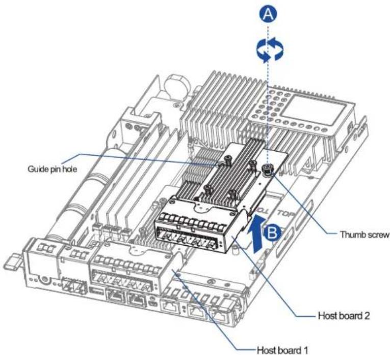
text_image
A Guide pin hole TOP B Thumb screw Host board 2 Host board 1- Remove the screw that secures the FBM to the controller (A), then remove the FBM from the module slot (B). Do the same step to the other FBM if you want it replaced.

text_image
A B Screw hole Module slots Screw hole- Orient and insert the replacement FBM's notch to the module slot's guide (A) in a 45^ angle, orient the screw notch on the screw hole (B), then secure the FBM to the board with a screw (C) you removed in step 3.
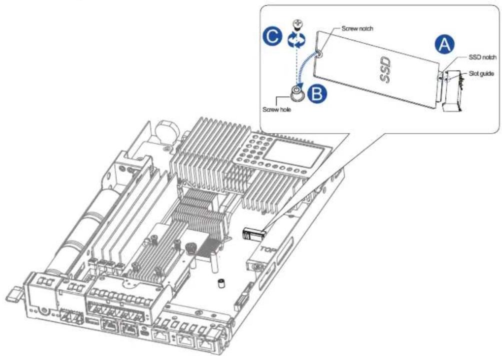
text_image
C Screw notch SSD A SSD notch Slot guide B Screw hole TOP- Install the host board back to the controller.
- Insert the controller back to the enclosure.
4.1.5 Replacing the host board
Before replacing the host board to the controller, you must take note of the following considerations:
- A controller/host board downtime may occur if you replace a host board for an upgrade.
- The firmware automatically restores the system to its factory settings when adding or replacing a host board.
To replace the host board:
- Shut down your system, unplug the power cords, then remove the controller. Wait for a minute for the remaining electric current to dissipate.
NOTE: See section 4.1.2 Replacing the controller module for details.
- Loosen the thumb screw that secures the host board to the controller (A), then gently lift the host board (B).
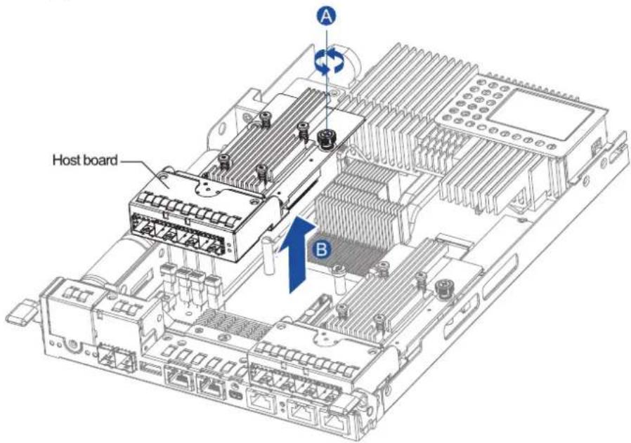
text_image
Host board A B- Orient the replacement host board to the controller's guide pin (A), place it carefully (B), then tighten the thumb screw to secure in place (C).
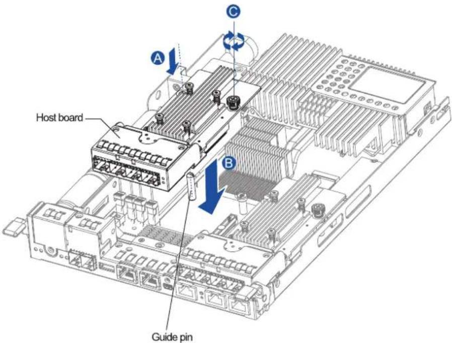
text_image
Host board Guide pin- Insert the controller back to the enclosure.
4.1.6 Replacing the hard drive
WARNING!
- Ensure to have the replacement ready before replacing the hard drive. DO NOT leave the drive tray open for long periods to prevent disruption of internal airflow.
- Handle the hard drives with extreme care. Hold them by the edges and avoid touching the circuits and interface connectors.
To replace the hard drive:
- Identify the faulty hard drive using the EonOne software.
NOTE: See section Hard drive designation for the order of the drive bays.
- When the faulty hard drive is located, push the release button to eject the drive tray, wait for 30 seconds for the drive to spin down, then pull out the tray using the spring handle.
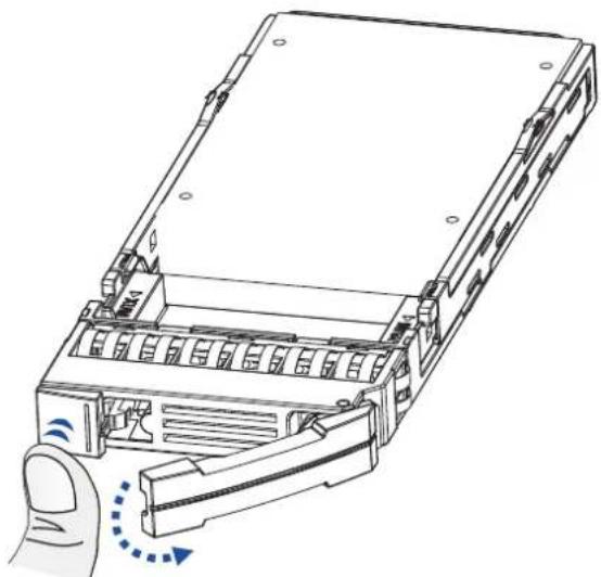
natural_image
Diagram of a computer drive showing internal components and a finger pressing a button (no text or symbols)- Remove the side clips from the tray (A) then remove the hard drive from the tray.
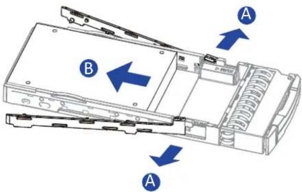
text_image
Diagram of a computer drive showing labeled components A and B with directional arrows indicating movement or assembly.NOTE: If the installed hard drive has an MUX board, remove it from the hard drive's connectors.
- Place the replacement hard drive on the tray, then secure the clips to the side of the tray.
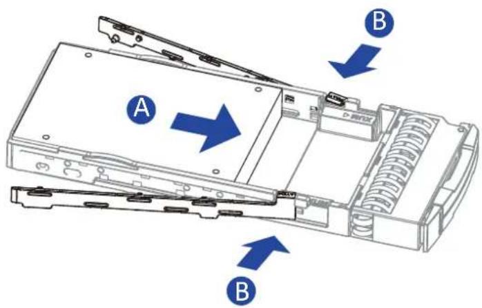
text_image
A B BNOTES:
-
If the hard drive requires an MUX board, install it first to the drive before assembling with the drive tray.
• Refer to section 2.2.3 Installing the hard drives for the detailed steps. -
Insert the assembled hard drive and tray to the enclosure with the spring handle open, then close the spring handle when the drive is fully inserted to the bay.
Appendices
A
Technical specification
Host board interface
| Fibre/iSCSI hybrid-host storage systems | |
| Host interface | 8 Gbps, 16 Gbps fibre host interface8 Gbps, 16 Gbps fibre + 2 onboard iSCSI |
| Drive interface/channel | Supports 12, 16, 24 channels of 3 Gbps, 6 Gbps, or 12 Gbps SAS, SATA-II/SATA-III, Near-line SAS series |
| SAS/iSCSI hybrid-host storage systems | |
| Host OS compatibility | Host OS independent |
| Host interface 3 Gbps, 6 Gbps, 12 Gbps multi-lane SAS | |
| Host channels Multiple SAS PHYs logically combined into 2 host channels per controller | |
| Drive interface/channel | Supports 12, 16, 24 channels of 3 Gbps, 6 Gbps, or 12 Gbps SAS, SATA-II/SATA-III, Near-line SAS series |
| iSCSI-host storage systems | |
| Host OS compatibility | Host OS independent, iSCSI offload utilities and hardware |
| Host interface RJ-45 Gigabit Ethernet/RJ-45 10 Gb Ethernet/10 Gb FCoE | |
| Drive interface/channel | Supports 12, 16, 24 channels of 3 Gbps, 6 Gbps, or 12 Gbps SAS, SATA-II/SATA-III, Near-line SAS series |
| Expansion enclosure models | |
| SAS interface 8 SMP PHYs interfaced to 2 or 3 12 Gbps SAS ports | |
| Drive interface/channel | Supports up to 12, 16, 24, 60 channels of 3 Gbps, 6 Gbps, or 12 Gbps SAS,SATA-II/SATA-III, Near-line series |
NOTE: The host board interface and specifications are subject to change without prior notice. For the latest specification and information, visit the official EonStor GSa website at https://www.infortrend.com/global/products/GSa.
Certifications
Summary
| Safety UL 60950-1 second edition | BSMI CNS 14336-1: 99 年版CB IEC 60950-1:2005 (Second Edition) + Am 1:2009+ Am 2:2013EAC TP TC 004/2011, TP TC 020/2011 |
| EMC CE EN 55032:2012 +AC:2013 / EN61000-3-2:2014EN 61000-3-3: 2013 / EN 55024:2010+A1:2015BSMI (CNS 13438)FCC (FCC Part 15, subpart B) | |
| Environment IEC 60068-2 | MIL-STD-810E/883EISTAASTM-D3332IPC-TM-650 |
| Others ISO7779/3744 | RoHSMicrosoft WHQL-Windows Server 2003 |
User warning
This is Class A Information Technology product which may cause radio frequency interference when used in a residential area, in which case the user will be required to take certain appropriate measures/troubleshooting.
警告使用者
Declaration of the presence condition of the restricted substance marking
| 設備名稱:儲存器 Equipment name | 型號(型式):GSa 3000 Series Type designation (Type) GSa 3000 Series | ||||||
| 單元 Unit | 鉛 Lead (Pb) | 汞 Mercury (Hg) | 鎘 Cadmium (Cd) | 六價鉻 Hexavalent chromium (Cr+6) | 多溴聯苯 brominated biphenyls (PBB) | 多溴二苯醚 brominated diphenyl ethers (PBDE) | |
| 外殼 Case | ○ ○ ○ ○ ○ | ||||||
| 電路板 PCB assembly | ○ ○ ○ ○ ○ | ||||||
| 電源供應器 Power supply | ○ ○ ○ ○ ○ | ||||||
| 硬碟 Hard disk | ○ ○ ○ ○ ○ | ||||||
| 電源線 Power cable | ○ ○ ○ ○ ○ | ||||||
| 風扇 Fan | ○ ○ ○ ○ ○ | ||||||
| 備考1. “超出0.1 wt %”及“超出0.01 wt %”係指限用物質之百分比含量超出百分比含量基準值。Note 1: “Exceeding 0.1 wt %” and “exceeding 0.01 wt %” indicate that the percentage content of the restricted substance exceeds the reference percentage value of presence condition.備考2. “○”係指該項限用物質之百分比含量未超出百分比含量基準值。Note 2: “○” indicates that the percentage content of the restricted substance does not exceed the percentage of reference value of presence.備考3. “-”係指該項限用物質為排除項目。Note 3: The “-” indicates that the restricted substance corresponds to the exemption. | |||||||
Contact information
Infortrend Technology, Inc. (HQ Taiwan)
Address: 8F, No. 102, Section 3, Jhongshan Road, Jhonghe District, New Taipei City 23544, Taiwan
Telephone: +886-2-2226-0126
Fax: +886-2-2226-0020
Email: sales.tw@infortrend.com
Website: https://www.infortrend.com/tw/Home
Support: http://support.infortrend.com/Account/Logon
Infortrend Japan, Inc.
Address: 6F Okayasu Bldg., 1-7-14 Shibaura, Minato-Ku, Tokyo, 105-0023 Japan
Telephone: +81-3-5730-6551
Fax: +81-3-5730-6552
Email: sales.jp@infortrend.com
Website: https://www.infortrend.com/jp/Home
Support: http://support.infortrend.com/Account/Logon
Infortrend Corporation (Americas)
Address: 435 Lakeside Dr. Sunnyvale, CA. 94085, USA
Telephone: +1-408-988-5088
Fax: +1-408-988-6288
Email: sales.us@infortrend.com
Website: https://www.infortrend.com/us/Home
Support: http://support.infortrend.com/Account/Logon
Infortrend Technology, Ltd. (Beijing)
Address: Room 1804, Block C, Ocean International Center, Dis. Chaoyang, Beijing, China
北京市朝阳区东四环中路远洋国际中心C座1804室
Telephone: +86-10-6310-6168
Fax: +86-10-59648252
Email: sales.cn@infortrend.com
Website: https://www.infortrend.com/cn/Home
Support: http://support.infortrend.com/Account/Logon
Infortrend Technology Office (Shanghai)
Address: Room 2306, 23/F, No. 88, Caoxi North Road, Xuhui District, Shanghai, China
上海市徐汇区漕溪北路88号23层2306室
Telephone: +86-10-63106168, +86-10-85866916, +86-10-85861801
Fax: +86-10-59648252
Email: sales.cn@infortrend.com
Website: https://www.infortrend.com/cn/Home
Support: http://support.infortrend.com/Account/Logon
Infortrend Technology Office (Southwest China)
Address: Room 1006, Building 2, Shangding International Building, No. 27 Renmin South
Road, Wuhou District, ChengduChina
Website: https://www.infortrend.com/cn/Home
Support: http://support.infortrend.com/Account/Logon
Infortrend Europe, Ltd. (EMEA)
Address: 57 Tempus Business Centre, Kingsclere Road, Basingstoke RG21 6XG UK
Telephone: +44-1256-305-220
Fax: +44-1256-305-221
Email: sales.es@infortrend.com, cs.eu@infortrend.com
Website: https://www.infortrend.com/uk/Home
Support: http://support.infortrend.com/Account/Logon
Infortrend worldwide sales offices
Spain and Portugal sales offices
Email: sales.es@infortrend.com, cs.eu@infortrend.com
Website: https://www.infortrend.com/es/Home
Support: http://support.infortrend.com/Account/Logon
Czech Republic sales office
Email: sales.cz@infortrend.com, cs.eu@infortrend.com
Website: https://www.infortrend.com/cz/Home
Support: http://support.infortrend.com/Account/Logon
France sales office
Email: sales.fr@infortrend.com, cs.eu@infortrend.com
Website: https://www.infortrend.com/fr/Home
Support: http://support.infortrend.com/Account/Logon
Italy sales office
Email: sales.it@infortrend.com, cs.eu@infortrend.com
Website: https://www.infortrend.com/it/Home
Support: http://support.infortrend.com/Account/Logon
Germany/Deutschland GmbH sales office
Email: sales.de@infortrend.com, cs.eu@infortrend.com
Website: https://www.infortrend.com/de/Home
Support: http://support.infortrend.com/Account/Logon
Poland sales office
Email: sales.pl@infortrend.com, cs.eu@infortrend.com
Website: https://www.infortrend.com/pl/Home
Support: http://support.infortrend.com/Account/Logon
Middle East sales offices
Email: sales.meat@infortrend.com
Website: https://www.infortrend.com/ae/Home
Support: http://support.infortrend.com/Account/Logon
India sales office
Email: sales.in@infortrend.com
Website: https://www.infortrend.com/in/Home
Support: http://support.infortrend.com/Account/Logon
Oceana sales office
Email: sales.aunz@infortrend.com
Website: https://www.infortrend.com/au/Home
Support: http://support.infortrend.com/Account/Logon