
Zadar - Synthesizer Xaoc - Free user manual and instructions
Find the device manual for free Zadar Xaoc in PDF.


| Product Type | Eurorack Synthesizer Module |
| Brand | Xaoc Devices |
| Model | Zadar |
| Number of Channels | 4 (A, B, C, D) |
| Envelope Shapes | 270 unique vector shapes in 27 banks |
| Time Range | 0.85 ms to 30 minutes |
| Deformation Parameters | Warp (temporal skew) and Response (amplitude bend) |
| Output Voltage | 0 to +10 V (unipolar) |
| CV Input Voltage Range | -10 V to +10 V |
| Power Consumption | +40 mA / -10 mA |
| Form Factor | Eurorack 10 hp (skiff compatible) |
| Display | OLED display with real-time feedback |
| Presets | 18 memory slots for full module settings |
| Expandability | Supports Nin expander (extra CV inputs and manual triggers) |
| Retriggering Modes | Digital (DG) and Analog (AN) |
| Chain/Loop Algorithms | 16 chaining algorithms for up to 4 channels |
| Phase Shift | Adjustable per channel (0-100% of cycle) |
| Repeat | Up to 100 cycles or infinite loop |
| Warranty | 1 year from date of purchase |
| Reverse Power Protection | Built-in (secures against reversed connection) |
Frequently Asked Questions - Zadar Xaoc
User questions about Zadar Xaoc
0 question about this device. Answer the ones you know or ask your own.
Ask a new question about this device
Download the instructions for your Synthesizer in PDF format for free! Find your manual Zadar - Xaoc and take your electronic device back in hand. On this page are published all the documents necessary for the use of your device. Zadar by Xaoc.
USER MANUAL Zadar Xaoc
Thank you for purchasing this XaoC Devices product. Zadar is a powerful, four-channel envelope, modulation, and transient generator, in a compact yet very complete, feature-rich package. It is capable of synthesizing a vast palette of envelope shapes starting from hundreds of shapes stored in the memory. These starting shapes are not mere wavetables, but flexible vectors that can be stretched (from a fraction of a millisecond to half an hour), flipped, warped, distorted, delayed, shuffled, repeated, and amplitude modulated in real time. A set of freely assignable CV inputs allows for external control of most parameters. Each channel can work independently or combined with other channels within one of the chaining and looping algorithms. Operating Zadar is quick and immediate, thanks to its accessible interface and crisp OLED display. The main screen displays all parameters together with the currently selected shape. Entering the simple 3-page menu (4 pages with Nin expander installed) is needed only for advanced settings.
INSTALLATION
The module requires 10hp worth of free space in the eurorack cabinet. The ribbon type power cable must be plugged into the bus board, paying close attention to polarity orientation. The red stripe indicates the negative 12V rail and should align with the dot, -12V or RED STRIPE marks on both the unit and the bus board. The module itself is secured against reversed power connection, however reversing the 16-pin header MAY
CAUSE SERIOUS DAMAGE to other components of your system by short-circuiting the +12V and +5V power rails. The module should be fastened by mounting the supplied screws before pow-
ering up. To better understand the device, we strongly advise the user to read through the entire manual before using the module.
VECTOR SHAPES
Each shape is a vector curve comprising 3 to 1000 breakpoints, and each segment interpolates between those breakpoints in real time. This method allows the shapes to be scaled from a fraction of a millisecond to half an hour, without any stepping artifacts that would otherwise be caused by undersampling. Similar to vector graphics, these synthesized envelopes are infinitely scalable and therefore have infinite resolution. This flexible approach allows shapes to be smooth when you want them to be smooth and sharp when you want them to be sharp — regardless of time scale.
Within the 2.0 firmware revision, there are 270 different shapes organized into 27 banks of 10 shapes. They have been carefully designed to suit a wide range of use, from essential synth envelopes to complex transients, from modulation cycles to rhythmic patterns, from quasi-random modulations to perfectly regular functions, from natural envelopes extracted from a variety of acoustic and electronic instruments to fractal abstractions and sequences. Several renowned artists have been invited to contribute extra “signature” shape banks (see the separate chart for a graphical representation of each shape). The essential feature of Zadar is that the vector shapes can be easily modified and modulated in a variety of ways — in fact, some have been deliberately designed to be deformed. Many of the complex shapes are intended for long, evolving envelopes (for example bank x), while others may serve better as snappy transients or resonator exciters (like bank u).
INTERFACE OVERVIEW
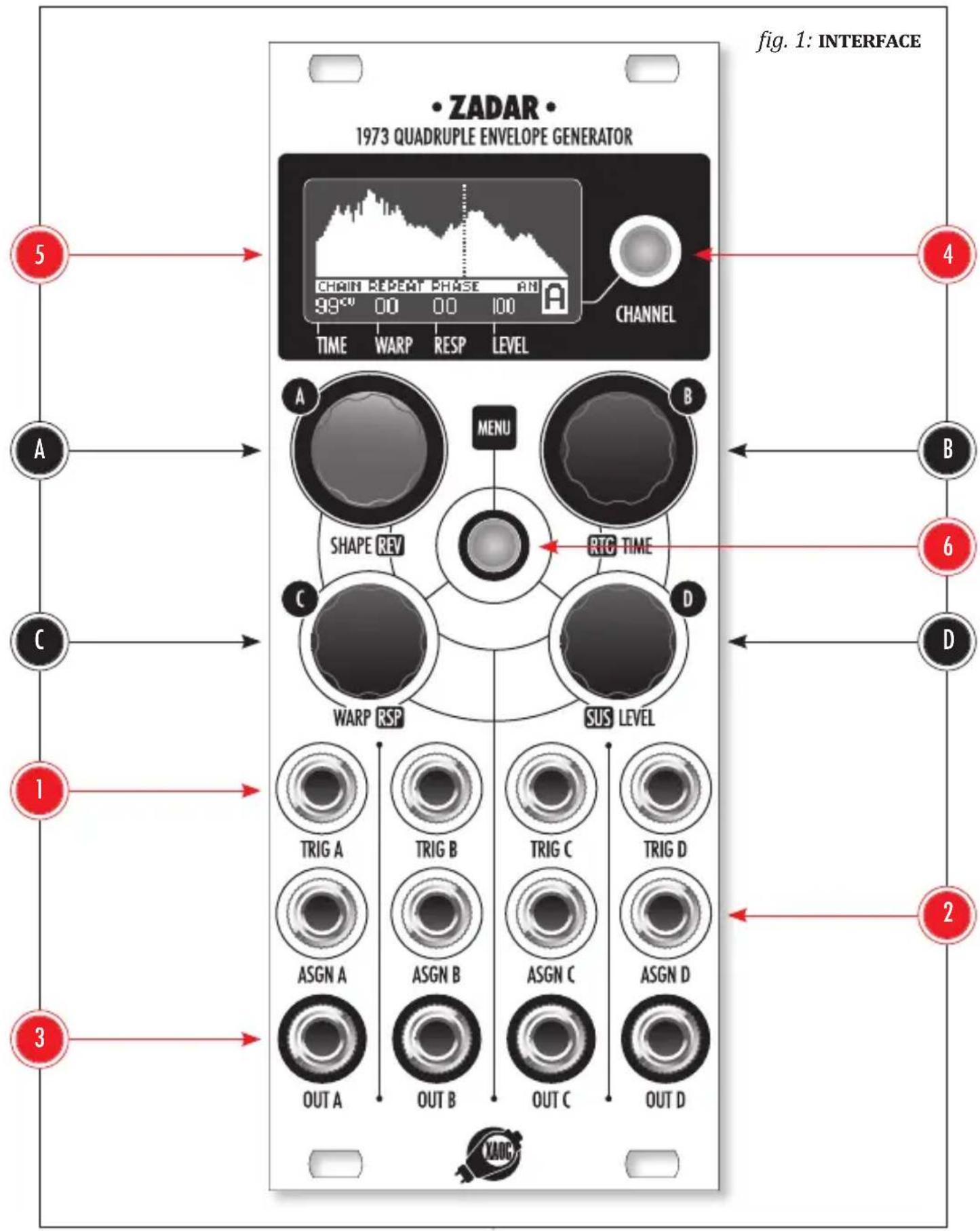
Zadar features four identical channels named A, B, C, D with dedicated CV inputs and outputs, all sharing a common set of controls. Within each channel, the TRIG input ① expects a trigger or gate impulse to initiate the envelope. The ASGN socket ② is an assignable CV input for external control (-10 to 10V) over a desired parameter. To learn how to assign a parameter, please read further down this manual. In each channel, the corresponding envelope is available at the OUT jack ③ as unipolar voltage (0 to 10V).
The set of four rotary “endless” encoders A, B, C, D is shared between the channels and dedicated to key parameters as described on the front panel.
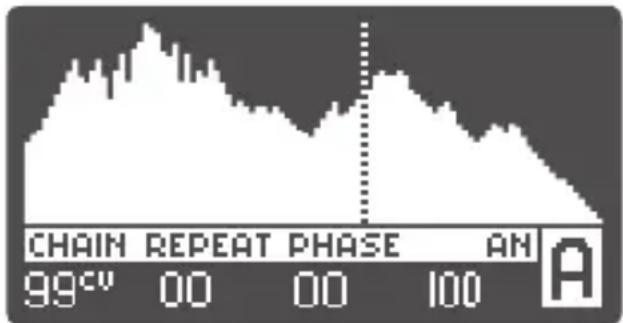
The blue-illuminated CHANNEL button 4 (lit when active) allows cycling through the channels. The OLED display 5 provides all the necessary visual feedback in real time, for the selected channel, with its name clearly displayed in the bottom-right corner (fig. 3).
NOTE: whenever the module remains idle for 10 minutes, the screen turns off; simply push or turn anything to re-enable.
Editing the envelope in the current channel is very easy:
Rotate the SHAPE/REV knob A to select a shape. Push the encoder to reverse the shape in time. The result can be observed on the display. Notice that shape and bank number are visible while selecting it.
Rotate the RTG/TIME knob Ⓑ to set the duration (0,85ms to 30min). The exact value in
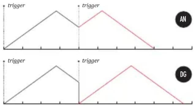
fig. 2: RETRIGGERING BEHAVIOR
line
| Time | Trigger | |------|---------| | 0 | 0 | | Peak | 0.8 | | Mid | 0.6 | | End | 0 |milliseconds is visible while turning the encoder, and the approximate percentage value is shown in smaller text. Push the encoder to toggle between “digital” and “analog” retriggering behavior, indicated by an appropriate DG or AN label on the screen. The DG option causes the envelope to restart from the beginning whenever a new trigger arrives which makes it instantly jump to 0V. The AN behavior is more complex — the restarting is from the first occurrence of the same voltage the envelope had when the trigger arrived, thus there is no glitch due to retriggering (fig. 2).
Press the WARP/RSP knob Ⓐ to toggle between two deformation parameters: WARP (temporal skew along the horizontal axis) and RESPONSE (amplitude bend along the vertical axis). Rotate the knob to change the value of a selected parameter, observing the deformation result and bipolar percentage value on the screen. Both deformations have a wide range, therefore each of these may serve as an essential tool for radical shape mangling or simple adjustment (e.g. adapting to the response of a VCA). Please be aware that at maximum setting, the deformation can be rather extreme, dramatically altering the shape from its starting point.
Press the SUS/LEVEL encoder D to toggle between SUSTAIN and LEVEL parameters. The SUSTAIN sets the point on the envelope to be held whenever a gate signal fed into TRIG input is high. The position is indicated with a vertical dashed line. NOTE: to disable the sustain stage, simply move the sustain point to the very end of the envelope until the display reads OFF.
The LEVEL parameter serves as an attenuator to the envelope amplitude, from 10V down to 10mV (and 0). The approximate value is displayed as a percentage of the entire voltage range, and the exact value in volts is visible during adjustment.
MENU: CV ASSIGNMENTS
The central, red-illuminated MENU button 6 cycles through three menu pages: CV input assignments, chain/loop settings, and preset management. NOTE: with the Nin expander
line
| Time | Value | |------|-------| | 99° | 00 | | 0 | 00 | | 100 | 100 |fig. 3: MAIN SCREEN
bar
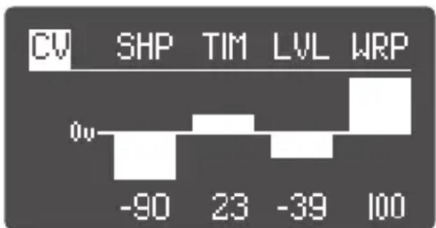
| Category | Value | |---|---| | CV | 0v | | SHP | -90 | | TIM | 23 | | LVL | -39 | | WRP | 100 |fig. 4: CV ASSIGNMENT MENU
module installed, a secondary CV assignments page appears that addresses the extra set of ASGN inputs on the expander. NOTE: encoders behave differently within the first two menu pages than in the top, default screen. Within these pages, encoders correspond to separate channels, and not the default parameters indicated on the panel.
While on the CV assignment page (fig. 4), push the corresponding channel's encoder to set its CV destination. The list of available parameters is browsed in a loop:
SHP — selects the envelope shape
TIM — adjusts duration
WRP — adjusts temporal warp
RSP — adjusts response
LVL — adjusts amplitude level
REP — selects the number of repeats
PHS — adjusts phase shift
REV — reverses the shape
SUS — sets the position of the sustain point
FRZ — freezes the envelope state
The degree of CV control of the selected parameter can be set by turning the encoder and is indicated by bipolar percentage bars with 0V in the middle. The interpretation of the display is straightforward — the higher the bar is displayed, the stronger the influence of the CV to the parameter value. NOTE: sensitivity of -50 for the TIME parameter offers an approximate 1V/octave response. Also, the REV and FRZ parameters react to CV in a binary manner. Like a comparator, the respective action is performed when the input CV exceeds the value as indicated by the bar. With REV, the envelope is reversed in relation to the current panel setting, and with FRZ, its state is frozen, thus pausing
the envelope and holding its current value at the instant the CV exceeds the threshold.
Press the MENU three times to leave this menu and cycle back to the main screen. Please note that the parameter assigned to CV is indicated by a small CV label next to its value.
MENU: CHAIN SETTINGS
Zadar offers several settings for complex behavior of individual channels as well as chaining and looping multiple envelopes across channels. It is possible to combine up to four envelopes into a chain, and furthermore, to define the cycle behavior within a chain. Quite sophisticated envelopes and modulation waveform patterns can be obtained this way. NOTE: even when chained, each envelope appears only on its dedicated output. In this menu, each knob corresponds to a separate channel. Push a knob to select the desired parameter and turn it to edit the value.
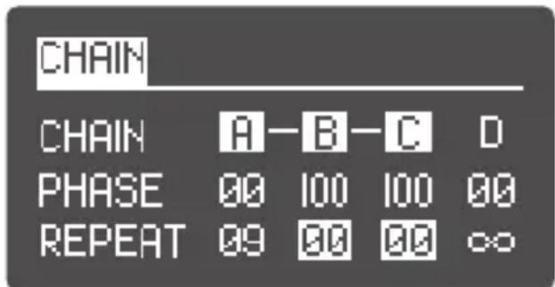
fig. 5: CHAIN MENU
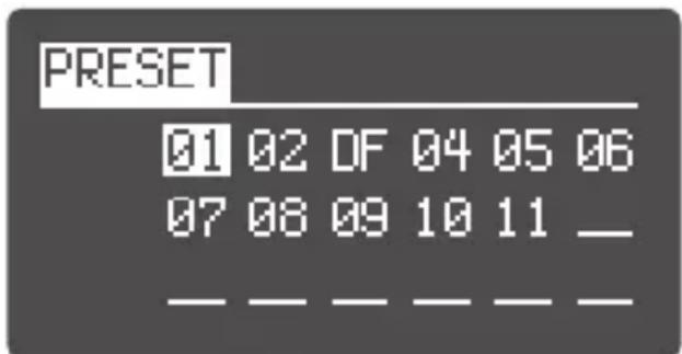
fig. 6: PRESET MANAGEMENT MENU
The selection of a CHAIN algorithm is performed by operating the red knob (associated with channel A). There are 16 available algorithms (fig. 7) defining various two-channel chain splits, chains of three or four channels, and looped derivatives of these. NOTE: envelopes chained to some other previous channel have their TRIG inputs inactive. Any unchained envelopes can still be used independently.
As long as the envelope remains unchained, the PHASE parameter simply defines trigger delay. The value displayed is a percentage of the entire cycle length and therefore depends on cycle duration — longer envelopes allow for longer delays.
Within the looped chain algorithms, the common behavior is for each envelope to start after the previous one ends. However, by adjusting the PHASE parameter, you can shift the next envelope so that it starts at any point within the cycle of the previous one. Therefore, it is possible to initiate all four envelopes at the same time (PHASE set to 0%) or make them start one after another (PHASE on channels B, C, D set to 100%. To loop the entire chain, also set channel A PHASE to 100%). In other words, within a chain, the PHASE parameter defines the phase shift with respect to the previous envelope in the chain. For example, if PHASE is set to 50%, the chained envelope will be triggered exactly at the halfway point of the preceding envelope. For more variations, you can experiment with setting a different number of repeats for each channel within a chain.
The REPEAT parameter defines how many times the current envelope will be repeated after completing the first cycle. As long as the envelope remains unchained, the REPEAT parameter sets
fig. 7: CHAIN ALGORITHMS
![A—B C D A B—C—D A B—C D A—B—C—D A B C—D A—B C—D A—B—C D [A—B] C D](/content/2026/05/819402/images/59d67cdbc0be84ebeb3cd07ccc1b478051143f59482d0840def0a3bb8d56a379.jpg)
the number of cycles from 0 to 100 or to infinity ( ). The last value yields an oscillator-like behavior. Repeating is also possible for envelopes that are parts of a chain, however, infinite cycles is then disabled.
Whenever the REPEAT value is greater than 0, the PHASE parameter will consider all the repetitions as one long cycle when calculating phase shift. Hence, the next envelope in a chain may be activated anytime during the repeats of the preceding one. NOTE: the default value of PHASE is zero. When a looped chain is selected from the algorithms, at least one PHASE value needs to be set to more than zero for the whole loop to function properly.
Press the MENU button two times to leave this menu and cycle back to the main screen. Please note that the activated functions are indicated by the small CHAIN, PHASE, and REPEAT labels below the shape depiction.
MENU: PRESET MANAGEMENT
Zadar offers a myriad of parameters and settings that can create quite complex programming configurations. Fortunately, it is possible to save your work for later use within the desired patching scenarios.
The red encoder A is used to navigate within the PRESET page (fig. 6). Rotate the knob
![A [B-C] D A B [C-D] [A-B-C] D A [B-C-D] [A-B-C-D] A-B [C-D] [A-B] C-D [A-B] C-D](/content/2026/05/819402/images/7dc66a4cc70d9d887071e9b18894d679beeee6a6447b19e33361a3406de6b391.jpg)
to select one of 18 preset slots. Then push the knob again to bring up the selection of possible operations: SAVE, LOAD, CLEAR, and DEFAULT PRESET. To prevent mistakes, a confirmation will be required for each operation. Each preset stores all the module settings. The default preset is recalled on module power-up. Press the MENU button once to leave this menu and cycle back to the main screen.
COPYING THE SETTINGS
Press and hold the CHANNEL button 4 to open the channel settings COPY menu. It is possible to paste the current channel settings to any other channel or all at once. The red encoder A is used to navigate within the COPY menu. To leave the menu without copying, select CANCEL.
QUICK SAVE
Zadar does not auto-save edited channel settings. To quickly save them, press and hold the MENU button 6. The operation is confirmed by MENU and CHANNEL buttons flashing once.
EXPANDABILITY
Nin, an expander module also available from Xaoc Devices, offers a second set of assignable CV inputs and manual trigger/gate push-buttons for more comfortable tweaking.
WARRANTY TERMS
XAOC DEVICES WARRANTS THIS PRODUCT TO BE FREE OF DEFECTS IN MATERIALS OR WORKMANSHIP, AND TO CONFORM WITH THE SPECIFICATIONS AT THE TIME OF SHIPMENT FOR A PERIOD OF ONE YEAR FROM THE DATE OF PURCHASE. DURING THAT PERIOD ANY MALFUNCTIONING OR DAMAGED UNITS WILL BE REPAIRED, SERVICED, AND CALIBRATED ON A RETURN-TO-FACTORY BASIS. THIS WARRANTY DOES NOT COVER ANY PROBLEMS RESULTING FROM DAMAGES DURING SHIPPING, INCORRECT INSTALLATION OR POWER SUPPLY, IMPROPER WORKING ENVIRONMENT, ABUSIVE TREATMENT OR ANY OTHER OBVIOUS USER-INFLICTED FAULT.
LEGACY SUPPORT
IF SOMETHING WENT WRONG WITH A XAOC PRODUCT AFTER THE WARRANTY PERIOD IS OVER, NO NEED TO WORRY, AS WE'RE STILL HAPPY TO HELP! THIS APPLIES TO ANY DEVICE, WHEREVER AND WHENEVER ORIGINALLY ACQUIRED. HOWEVER, IN SPECIFIC CASES, WE RESERVE THE RIGHT TO CHARGE FOR LABOR, PARTS AND TRANSIT EXPENSES WHERE APPLICABLE.
RETURN POLICY
THE DEVICE INTENDED FOR REPAIR OR REPLACEMENT UNDER WARRANTY NEEDS TO BE SHIPPED IN THE ORIGINAL PACKAGING ONLY, SO PLEASE KEEP IT JUST IN CASE. ALSO, A FILLED RMA FORM MUST BE INCLUDED. XAOC DEVICES CAN NOT TAKE ANY RESPONSIBILITY FOR DAMAGES CAUSED DURING TRANSPORT. PRIOR TO SENDING US ANYTHING, PLEASE CONTACT US AT SUPPORT@XAOCDEVICES.COM. NOTE THAT ANY UNSOLICITED PARCEL WILL BE REJECTED AND RETURNED!
GENERAL INQUIRIES
FOR USER FEEDBACK SUGGESTIONS, DISTRIBUTION TERMS, FEEL FREE TO CONTACT XAOC DEVICES AT INFO@XAOCDEVICES.COM. PLEASE VISIT THE XAOCDEVICES.COM FOR INFORMATION ABOUT THE CURRENT PRODUCT LINE, USER MANUALS, FIRMWARE UPDATES, TUTORIALS, AND MERCHANDISE.
WORKING CLASS ELECTRONICS®

WRITTEN BY T. MIRT, M. ŁOJEK, M. BARTKOWIAK. PROOFREADING AND EDITING BY B. NOLL. DESIGNED BY M. ŁOJEK. ALL RIGHTS RESERVED. CONTENT COPYRIGHT © 2019 XAOC DEVICES. COPYING, DISTRIBUTION OR ANY COMMERCIAL USE IN ANY WAY IS STRICTLY PROHIBITED AND REQUIRES THE WRITTEN PERMISSION BY XAOC DEVICES. SPECIFICATIONS ARE SUBJECT TO CHANGE WITHOUT PRIOR NOTICE.
MAIN FEATURES
Four independent channels
270 unique vector shapes
Cycle time range: 0,85ms to 30min
Shapes can be radically modified in two dimensions
Immediate operation, accessible interface
Complex envelope looping and chaining features
Assignable CV inputs to control nearly every parameter
18 preset slots
TECHNICAL DETAILS
Eurorack synth compatible
10hp, skiff friendly
Current draw: +40 ~mA / - 10 ~mA
Reverse power protection

Brand : Xaoc
Model : Zadar
Category : Synthesizer