Instant IAP-175 - Access Point Aruba - Free user manual and instructions
Find the device manual for free Instant IAP-175 Aruba in PDF.


| Product Type | Outdoor Dual-Radio Dual-Band IEEE 802.11 a/b/g/n Wireless Access Point |
| Model Variants | IAP-175P (PoE+ powered) and IAP-175AC (AC powered) |
| Dimensions (H x W x D) | 10.2 x 9.4 x 4.1 in (26 x 24 x 10.5 cm) |
| Weight | 7 lbs (3.25 kg) |
| Power Input | IAP-175P: 48 VDC 802.3at PoE+; IAP-175AC: 100-240 VAC |
| Maximum Power Consumption | 18 W (excluding PoE output on IAP-175AC) |
| Power Output (IAP-175AC) | 802.3af PoE (PSE) on Ethernet port |
| Wireless Standards | 802.11a/b/g/n (2.4 GHz and 5 GHz) |
| Frequency Bands | 2.400-2.4835 GHz, 5.150-5.850 GHz (country-specific) |
| Maximum Transmit Power | 25 dBm (limited by regulatory requirements) |
| Antenna Interfaces | 4 x N-type female (2 for 2.4 GHz, 2 for 5 GHz) |
| Ethernet Interface | 1 x 10/100/1000BASE-T (RJ-45) with PoE+ (IAP-175P) or PoE out (IAP-175AC) |
| Other Interfaces | 1 x USB console (serial); 1 x AC power connector (IAP-175AC only) |
| Mounting Options | Wall or pole mount (bracket included) |
| Operating Temperature | IAP-175P: -30°C to 60°C; IAP-175AC: -40°C to 55°C |
| Storage Temperature | -40°C to 70°C |
| Relative Humidity | 5% to 95% non-condensing |
| Altitude | Up to 9,850 ft (3,000 m) |
| Wind Resistance | Operates up to 165 mph (265 km/h) |
| Lightning Protection | Requires Aruba AP-LAR-1 lightning arrestor on each antenna port |
| Grounding Resistance | Less than 5 ohms |
| LED Indicators | Power/Ready, Ethernet link, Radio status, RSSI (4-step bars per radio) |
| Package Contents | Access point, mounting bracket, solar shield, pole anchors, bolts, weatherproof caps, RJ-45 connector kit (depending on model), USB console cable, installation guide |
Frequently Asked Questions - Instant IAP-175 Aruba
User questions about Instant IAP-175 Aruba
0 question about this device. Answer the ones you know or ask your own.
Ask a new question about this device
Download the instructions for your Access Point in PDF format for free! Find your manual Instant IAP-175 - Aruba and take your electronic device back in hand. On this page are published all the documents necessary for the use of your device. Instant IAP-175 by Aruba.
USER MANUAL Instant IAP-175 Aruba
Aruba IAP-175 Outdoor Instant Access Point Installation Guide
The Aruba IAP-175 is a resilient, environmentally hardened, outdoor rated, dual-radio, dual-band IEEE 802.11 a/b/g/n wireless access point. This outdoor access point is part of Aruba's comprehensive wireless network solution. The IAP-175 can operate as an Aruba virtual controller or as a member of an Aruba Instant wireless network.

The IAP-175 requires Aruba 3.0 Instant or later.
There are two versions of the IAP-175, which mainly differ in the way they receive power.
• IAP-175P: PoE+ powered (802.3at)
• IAP-175AC: AC powered (100 - 240 VAC)

The IAP-175AC can function as a Power Sourcing Equipment (PSE) device by providing power through its Ethernet port in compliance with the IEEE 802.3af standard.
Guide Overview
- "IAP-175 Hardware Overview" on page 3 provides a detailed hardware overview of the three IAP-175 models.
- "Outdoor Planning and Deployment Considerations" on page 7 provides key questions to ask and items to consider when deploying an outdoor wireless network.
- "Installing Antennas" on page 12 describes how to installing antennas.
- "Weatherproofing Connections" on page 12 provides instructions on weatherproofing the AP's connectors.
- "Installing the IAP-175" on page 19 describes the multi-step process for a successful installation and deployment of an IAP-175.
- "Safety and Regulatory Compliance" on page 30 provides an overview of safety and regulatory compliance information.
IAP-175 Operations
• Wireless access point (IEEE 802.11 a/b/g/n)
• Wireless air monitor (IEEE 802.11 a/b/g/n)
- Enterprise mesh point
- Enterprise mesh portal
- Protocol-independent networking functionality
- IAP-175P: IEEE 802.3at Power over Ethernet+ (PoE+) compatible
• IAP-175AC: IEEE 802.3af Power Sourcing Equipment (PSE) device
Package Contents
• IAP-175 Access Point
• IAP-175 Mounting Bracket
- Solar Shield
- Pole Anchors x 2
- M4 x 16 bolts, flat washers, and spring washers x4 (These bolts are attached to the solar shield)
• M6 x 30 bolts, flat washers, and spring washers x2
- M4 x 12 bolt, external-tooth washer, and OT copper lug x1
- M8 x 110 bolt, flat washers, spring washers, and nuts x4
• Metal Weatherproof Caps x2 for use on unused antenna interfaces
- RJ-45 Connector Kit with plastic RJ-45 connector (IAP-175P only)
- RJ-45 Connector Kit with metal RJ-45 connector (IAP-175AC only)
• USB Console Cable
• Installation Guide

NOTE
Inform your supplier if there are any incorrect, missing, or damaged parts. If possible, retain the carton, including the original packing materials. Use these materials to repack and return the unit to the supplier if needed.
IAP-175 Hardware Overview
The following section describes the hardware features of the IAP-175.
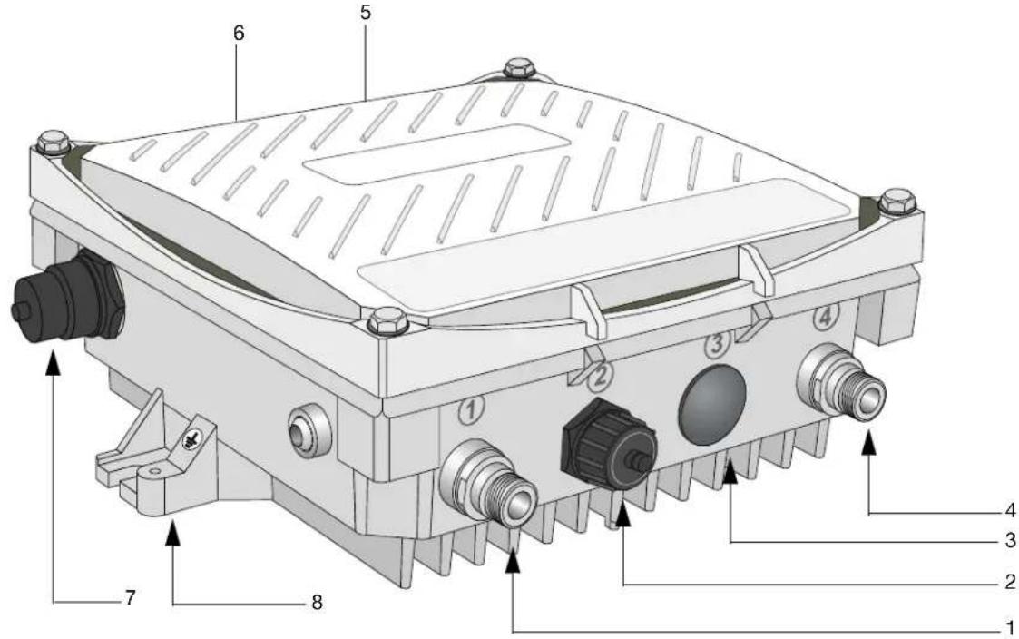
Figure 1 IAP-175 Overview (IAP-175P shown)
text_image
Technical diagram of an electronic device with numbered components and directional arrows indicating assembly or labeling.| 1 Antenna Interface (Radio 1) 5 Antenna Interface (Radio 0) | ||
| 2 USB Console Interface 6 Antenna Interface (Radio 1) | ||
| 3 Reserved (IAP-175P) or Power Interface (IAP-175AC) | 7 Ethernet Interface (PoE) | |
| 4 Antenna Interface (Radio 0) 8 Grounding Point | ||
Antenna Interface
The IAP-175 requires the use of detachable outdoor-rated antennas. Select the correct antenna type to support the required frequency band (2.4 or 5 GHz) and the desired coverage pattern.
The IAP-175 is equipped with four, female N-type antenna interfaces; two on the top of the AP and two on the bottom. The interfaces are grouped into diversity pairs, one pair is marked R0 (Radio 0) and the other pair marked as R1 (Radio 1). R0 supports the 5 GHz frequency band and R1 supports the 2.4 GHz radio band.
USB Console Interface
A USB serial console port is provided for connection to a terminal, allowing direct local management. Use the included USB console cable to connect to the AP. You can download the necessary driver for USB-UART adapter from support.arubanetworks.com under the Tools & Resources tab.
Use the following setting to access the terminal:
Table 1 Console Settings
| Baud Rate | Data Bits | Parity | Stop Bits | Flow Control |
| 9600 | 8 | None | 1 | None |
Power Interface
The type of power interface on your IAP-175 depends on which model you have purchased.
- IAP-175P: This version does not include a power interface since it is only powered by PoE+ (802.3at).
• IAP-175AC: 1x AC power connector

For the IAP-175AC, only use the AC power cord with model number CBL-AC-INTL.
The IAP-175 is equipped with a 10/100/1000Base-T Gigabit Ethernet port for wired network connectivity. On the IAP-175P, this port also supports IEEE 802.3at Power over Ethernet (PoE), accepting 48 VDC as a standards-defined powered device (PD) from a power sourcing equipment (PSE) device, such as a PoE midspan injector. Inversely, the IAP-175AC can act as a PSE device to provide IEEE802.3af PoE power to devices connected to the Ethernet port.
Grounding Point
Always remember to protect your IAP-175 by installing grounding lines. The ground connection must be complete before connecting power to the IAP-175 enclosure. Ensure that the resistance is less than 5 ohm between the ground termination point and the grounding tier.
IAP-175P LED Status Indicators
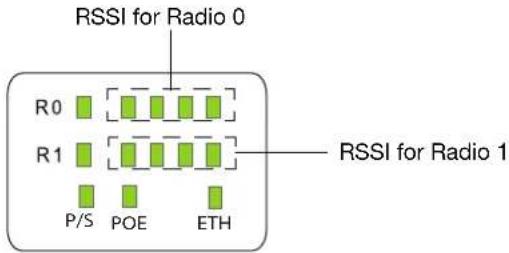
The IAP-175 include visual indicators for power, link, and radio status. Additionally, each radio has a four-LED array that indicates received signal strength (RSSI).

The RSSI LED indicators represent varying degrees in the RSSI level. The absence of a signal is indicated by no LED response, and full signal strength is indicated when all four LEDs are active and lit.
Figure 2 LED Layout
text_image
RSSI for Radio 0 R0 R1 P/S POE ETH RSSI for Radio 1Table 2 lists the meanings of the LEDs on the IAP-175P outdoor access point.
Table 2 IAP-175P LED Status Indicators
| LED Function Indicator Status | |||
| P/S AP Power/Ready | Status | Off No power to AP | |
| Blinking Device booting, not ready | |||
| On Device ready | |||
| POE N/A N/A Not currently used | |||
| ENT LAN/Network Link | Status | Off Ethernet link unavailable | |
| On (Amber) 10/100 Mbs | Ethernet link negotiated | ||
| On (Green) | 1000 Mbs Ethernet link negotiated | ||
| Blinking Traffic on Ethernet link | |||
| R0 | Radio 0 Status | Off Radio 0 disabled | |
| On (Amber) Radio 0 enabled in WLAN mode | |||
| Blinking Air Monitor (AM) mode | |||
| R1 | Radio 1 Status | Off Radio 1disabled | |
| On (Blue) | Radio 1 enabled in WLAN mode | ||
| Blinking Air Monitor (AM) mode | |||
| RSSI (Radio 0) | RSSI Level for Radio 0 | Off RSSI disabled/no signal | |
| 4 Step Progressive Bars (Red)25/50/75/100% | Each bar represents a progressive increase in signal strength, with 4 bars representing maximum signal strength (100%).Minimum data rate: One lit LEDsMaximum data rate: Four lit LEDs | ||
| RSSI (Radio 1) | RSSI Level for Radio 1 | Off RSSI disabled/no signal | |
| 4 Step Progressive Bars (Blue)25/50/75/100% | Each bar represents a progressive increase in signal strength, with 4 bars representing maximum signal strength (100%).Minimum data rate: One lit LEDsMaximum data rate: Four lit LEDs | ||
IAP-175AC LED Status Indicators
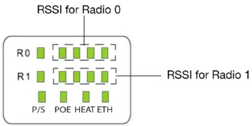
The IAP-175 include visual indicators for power, link, heat and radio status. Additionally, each radio has a four-LED array that indicates received signal strength (RSSI).

The RSSI LED indicators represent varying degrees in the RSSI level. The absence of a signal is indicated by no LED response, and full signal strength is indicated when all four LEDs are active and lit.
Figure 3 LED Layout
text_image
RSSI for Radio 0 R0 R1 P/S POE HEAT ETH RSSI for Radio 1Table 3 lists the meanings of the LEDs on the IAP-175AC outdoor access points.
Table 3 IAP-175AC LED Status Indicators
| LED Function Indicator | Status | ||
| P/S AP Power/Ready | Status | Off No power to AP | |
| Blinking Device booting, not ready | |||
| On Device ready | |||
| POE Displays PSE | power output status | Off Non-powered device(0Ω1MΩ) | |
| Green Port on (25kΩ) | 1 Flash: Low signature resistance (300Ω2 Flashes: High signature resistance (33kΩ5 Flashes: Port overload fault9 Flashes: Power management allocation exceeded | ||
| Heat Displays the | heating status of low temperature | Off Unit is not in heating status | |
| Blinking (Blue) Unit is pre-heating | |||
| ENT | LAN/Network Link Status | Off Ethernet link unavailable | |
| On (Amber) | 10/100 Mbs Ethernet link negotiated | ||
| On (Green) | 1000 Mbs Ethernet link negotiated | ||
| Blinking Traffic on Ethernet link | |||
| LED Function Indicator Status | |||
| R0 Radio 0 Status Off Radio 0 disabled | |||
| On (Amber) Radio 0 enabled in WLAN mode | |||
| Blinking Air Monitor (AM) mode | |||
| R1 Radio 1 Status Off Radio 1disabled | |||
| On (Blue) Radio 1 enabled in WLAN mode | |||
| Blinking Air Monitor (AM) mode | |||
| RSSI (Radio 0) RSSI Level for Radio 0 | Off RSSI disabled/no signal | ||
| 4 Step Progressive Bars (Red)25/50/75/100% | Each bar represents a progressive increase in signal strength, with 4 bars representing maximum signal strength (100%).Minimum data rate: One lit LEDsMaximum data rate: Four lit LEDs | ||
| RSSI (Radio 1) RSSI Level for Radio 1 | Off RSSI disabled/no signal | ||
| 4 Step Progressive Bars (Blue)25/50/75/100% | Each bar represents a progressive increase in signal strength, with 4 bars representing maximum signal strength (100%).Minimum data rate: One lit LEDsMaximum data rate: Four lit LEDs | ||
Outdoor Planning and Deployment Considerations
Prior to deploying an outdoor wireless network, the environment must be evaluated to plan for a successful Aruba WLAN deployment. Successfully evaluating the environment enables the proper selection of Aruba APs and antennas and assists in the determination of their placement for optimal RF coverage. This process is considered WLAN or RF planning and Aruba's system engineers can assist in the outdoor planning process.

Improper termination of access points installed in the United States configured to non_US model controllers will be violation of the FCC Grant of equipment authorization. Any such willful or intentional violation may result in a requirements by FCC to immediate termination of operation and my be subject to forfeiture (47 CFR 1.80).
Scale Requirements
The potentially immense scale of outdoor deployments requires consideration of factors that may not be as important in a typical indoor deployment:
- Range (distance): Range or distance between APs must be taken into account during the planning phase. Available AP mounting locations are often far less flexible in an outdoor environment. Regardless of these outdoor restrictions, the desired goal is to achieve results similar to an indoor deployment: a “dense” RF deployment that supports advanced Aruba features, such as ARM, efficient client roaming, and failover.
- Elevation: Proper consideration and planning for elevation differences between APs (AP to AP) and AP to Client can be critical to success. To plan for these differences in elevation, it is important to understand the 3D coverage pattern provided by the antennas that will be deployed in the environment.
- Non-Fixed Considerations: The RF environment might change on a day to day basis. Keep non-fixed items, such as shipping containers, vehicles, and future building construction, in mind when planning for an outdoor deployment.
Identifying Known RF Absorbers/Reflectors/Interferences Sources
Identifying known RF absorbers/reflectors/interference sources while out in the field during the installation phase is critical. Even though outdoor environments consist of fewer RF absorbers/reflectors/interference sources compared to indoor environments, ensure that these sources are identified and taken into consideration when installing and mounting an AP to its fixed outdoor location.
RF Absorbers
- Cement/Concrete
• Natural Items: Trees/vegetation - Brick
RF Reflectors
- Metal Objects: Roof-installed air-conditioning equipment, chain link fences (depending on aperture size), other wire fences, or water pipes
RF Interference Sources
• Other 802.11a/b/g/n or broadband access equipment operating nearby
- Industrial RF welding equipment or other Industrial, Scientific and Medical (ISM) equipment that utilizes RF to heat or alter the physical properties of materials
• Military, Commercial Aviation or Weather Radar Systems
Line of Sight (Radio Path Planning)
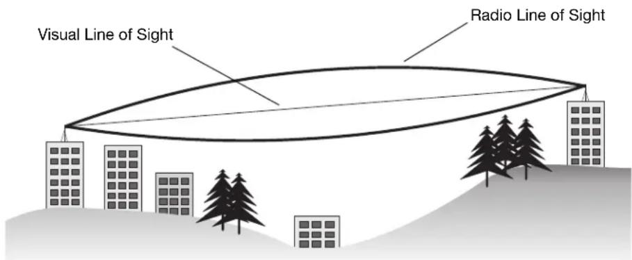
A wireless bridge or mesh link requires a “radio line of sight” between the two antennas for optimum performance. The concept of radio line of sight involves the area along a link through which the bulk of the radio signal power travels. This area is known as the first Fresnel Zone of the radio link. For a radio link, no object (including the ground) must intrude within 60% of the first Fresnel Zone.
Figure 4 illustrates the concept of a good radio line of sight.
Figure 4 Line of Sight
text_image
Visual Line of Sight Radio Line of SightIf there are obstacles in the radio path, there may still be a radio link but the quality and strength of the signal will be affected. Calculating the maximum clearance from objects on a path is important as it directly
affects the decision on antenna placement and height. It is especially critical for long-distance links, where the radio signal could easily be lost.
When planning the radio path for a wireless bridge or mesh link, consider these factors:
- Avoid any partial line of sight between the antennas
- Be cautious of trees or other foliage that may be near the path, or may grow and obstruct the path.
- Be sure there is enough clearance from buildings and that no building construction may eventually block the path.
- For very long distance links, the curvature of the earth (20 cm per km) may need to be considered in the calculation of relative heights.
- Check the topology of the land between the antennas using topographical maps, aerial photos, or even satellite image data (software packages are available that may include this information for your area)
- Avoid a path that may incur temporary blockage due to the movement of cars, trains, or aircraft.
Antenna Height
A reliable wireless bridge or mesh link is usually best achieved by mounting the antennas at each end high enough for a clear radio line of sight between them. The minimum height required depends on the distance of the link, obstacles that may be in the path, topology of the terrain, and the curvature of the earth (for links over 3 miles).
For long-distance links, the AP may have to be mounted on masts or poles that are tall enough to attain the minimum required clearance. Use the following table to estimate the required minimum clearance above the ground or path obstruction (for 5 GHz bridge links).
Table 4 Antenna Minimum Height and Clearance Requirements
| Total Link Distance | Max Clearance for 60% of First Fresnel Zone at 5.8 GHz | Approximate Clearance for Earth Curvature | Total Clearance Required at Mid-point of Link |
| 0.25 mile (0.402 km) 4.6 ft (1.4 m) 0.007 ft (0.002 m) | 4.6 ft (1.4 m) | ||
| 0.5 mile (0.805 km) 6.2 ft (1.9 m) 0.03 ft (0.010 m) | 6.2 ft (1.9 m) | ||
| 1 mile (1.6 km) 8.9 ft (2.7 m) 0.13 ft (0.04 m) 8.9 ft (2.7 m) | |||
| 2 miles (3.2 km) 12.5 ft (3.8 m) 0.5 ft (0.15 m) 13.1 ft (4.0 m) | |||
| 3 miles (4.8 km) 15.4 ft (4.7 m) 1.0 ft (0.3 m) | 16.4 ft (5.0 m) | ||
| 4 miles (6.4 km) 17.7 ft (5.4 m) 2.0 ft (0.6 m) | 19.7 ft (6.0 m) | ||
| 5 miles (8 km) | 20 ft (6.1 m) | 3.0 ft (0.9 m) | 23 ft (7.0 m) |
| 7 miles (11.3 km) | 23.6 ft (7.2 m) 6.2 ft (1.9 m) | 30 ft (9.1 m) | |
| 9 miles (14.5 km) | 27 ft (8.2 m) | 10.2 ft (3.1 m) 37 ft (11.3 m) | |
| 12 miles (19.3 km) | 30.8 ft (9.4 m) | 18.0 ft (5.5 m) | 49 ft (14.9 m) |
| 15 miles (24.1 km) | 34.4 ft (10.5 m) | 28.0 ft (8.5 m) | 62.7 ft (19.1 m) |

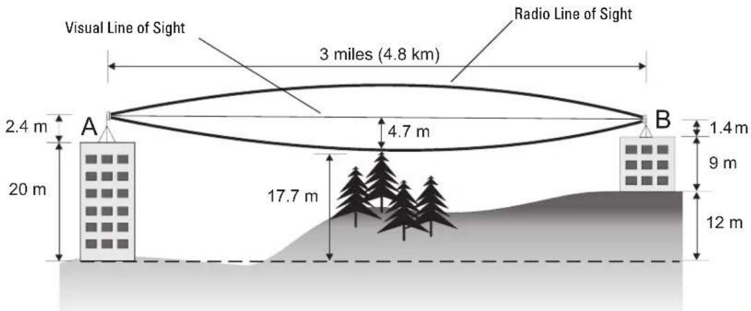
To avoid any obstruction along the path, the height of the object must be added to the minimum clearance required for a clear radio line of sight. Consider the following simple example, illustrated in Figure 5.
Figure 5 Antenna Height and Line of Sight
text_image
Visual Line of Sight 3 miles (4.8 km) Radio Line of Sight 2.4 m A 4.7 m B 1.4 m 20 m 17.7 m 9 m 12 mA wireless bridge or mesh link is deployed to connect building A to building B, which is located three miles (4.8 km) away. Mid-way between the two buildings is a small tree-covered hill. From the above table it can be seen that for a three-mile link, the object clearance required at the mid-point is 4.7 m (15.4 ft). The tree tops on the hill are at an elevation of 17.7 m (58.1 ft), so the antennas at each end of the link need to be at least 22.4 m (73.5 ft) high. Building A is six stories high, or 20 m (66 ft), so a 2.4 m (7.9 ft) mast or pole must be constructed on its roof to achieve the required antenna height. Building B is only three stories high, or 9 m (30 ft), but is located at an elevation that is 12 m (39 ft) higher than building A. To mount an antenna at the required height on building B, a mast or pole of 1.4 m (4.6 ft) is needed.

Never construct a radio mast, pole, or tower near overhead power lines.

Local regulations may limit or prevent construction of a high radio mast or tower. If your wireless bridge or mesh link requires a high radio mast or tower, consult a professional contractor for advice.
Antenna Position and Orientation
Once the required antenna height has been determined, other factors affecting the precise position of the wireless bridge or mesh link must be considered:
- Be sure there are no other radio antennas within 2 m (6 ft) of the wireless bridge or mesh link. These include other WiFi radio antennas.
- Place the wireless bridge or mesh link away from power and telephone lines.
- Avoid placing the wireless bridge or mesh link too close to any metallic reflective surfaces, such as roof-installed air-conditioning equipment, tinted windows, wire fences, or water pipes. Ensure that there is at least 5 feet clearance from such objects.
- The wireless bridge or mesh link antennas at both ends of the link must be positioned with the same polarization direction, either horizontal or vertical. Proper alignment helps to maximize throughput.
Radio Interference
The avoidance of radio interference is an important part of wireless link planning. Interference is caused by other radio transmissions using the same or an adjacent channel frequency. You should first scan your proposed site using a spectrum analyzer to determine if there are any strong radio signals using the 802.11a/b/g channel frequencies. Always use a channel frequency that is furthest away from another signal.
If radio interference is still a problem with your wireless bridge or mesh link, changing the antenna direction may improve the situation.
Weather Conditions
When planning wireless bridge or mesh links, you must take into account any extreme weather conditions that are known to affect your location. Consider these factors:
- Temperature: The wireless bridge or mesh link is tested for normal operation in temperatures from -30°C to 55°C. Operating in temperatures outside of this range may cause the unit to fail.
- Wind Velocity: The wireless bridge or mesh link can operate in winds up to 165 miles per hour. You must consider the known maximum wind velocity and direction at the site and be sure that any supporting structure, such as a pole, mast, or tower, is built to withstand this force.
- Lightning: To protect against lightning induced surges, the IAP-175 requires lightning protection on the radio interface ports.

An Aruba Lightning Arrestor, AP-LAR-1, must be installed on each antenna port for protection against lightning induced surges. Failure to use an AP-LAR-1 can void the warranty of an Aruba outdoor AP model and renders the AP susceptible to failure from lightning induced surges
- Rain: The wireless bridge or mesh link is weatherproofed against rain. However, it is recommended to apply weatherproof sealing tape around the Ethernet port and antenna connectors for extra protection. If moisture enters a connector, it may cause a degradation in performance or even a complete failure of the link.
- Snow and Ice: Falling snow, like rain, has no significant effect on the radio signal. However, a buildup of snow or ice on antennas may cause the link to fail. In this case, the snow or ice has to be cleared from the antennas to restore operation of the link.
Ethernet Cabling
When a suitable antenna location has been determined, you must plan a cable route from the wireless bridge or mesh link outdoors to a suitable power and/or network source.
Consider these points:
• The Ethernet cable length should never be longer than 90 m (295 ft).
• Determine a building entry point for the cable (if applicable).
- Determine if conduits, bracing, or other structures are required for safety or protection of the cable.
- For lightning protection at the power injector end of the cable, consider using a lightning arrestor immediately before the cable enters the building
Grounding
It is important that the wireless bridge or mesh link, cables, and any supporting structures are properly grounded. Each IAP-175 access point includes a grounding screw for attaching a ground wire. Be sure that grounding is available and that it meets local and national electrical codes. Ground the access point first using the external ground stud on the unit before making any other connection.
Installing Antennas
- Before connecting the antennas, identify which of your antennas are 2.4 GHz and which are 5 GHz. On the AP-175, the 2.4 GHz antennas must be installed the R1 radio interfaces and the 5.0 GHz must be installed on the R0 radio interfaces.
- After identifying which antennas will go where, install them by placing the antenna connector over the corresponding connector and the AP and turning the connector clockwise until hand tight. Repeat this process for each antenna.
- Place the included metal weatherproof caps over any unused antenna interfaces by turning them clockwise until hand tight.
Weatherproofing Connections
Weatherproofing your antenna and/or cable connections on your outdoor AP is essential to reliability and longevity of your product. This process prevents water from entering the AP or antennas through the connectors.
A good weatherproofing job consists of three wrappings:
- electrical tape
- butyl rubber
- electrical tape
The first wrapping of tape should be at least two layers, followed by a single wrap of butyl rubber, and four-layer wrap of electrical tape. This provides good protection from water, heat, and other potential hazards that could damage your AP or antennas.
Additionally, wrap your connections such that water is always directed down and away from connections.
Required Items and Tools
• 3/4" (19 mm) Vinyl Electrical Tape
- Butyl Rubber Tape
- Knife or Box Cutter
Types of Connections
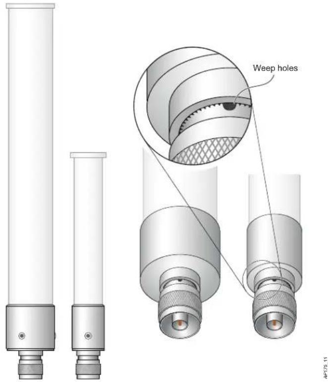
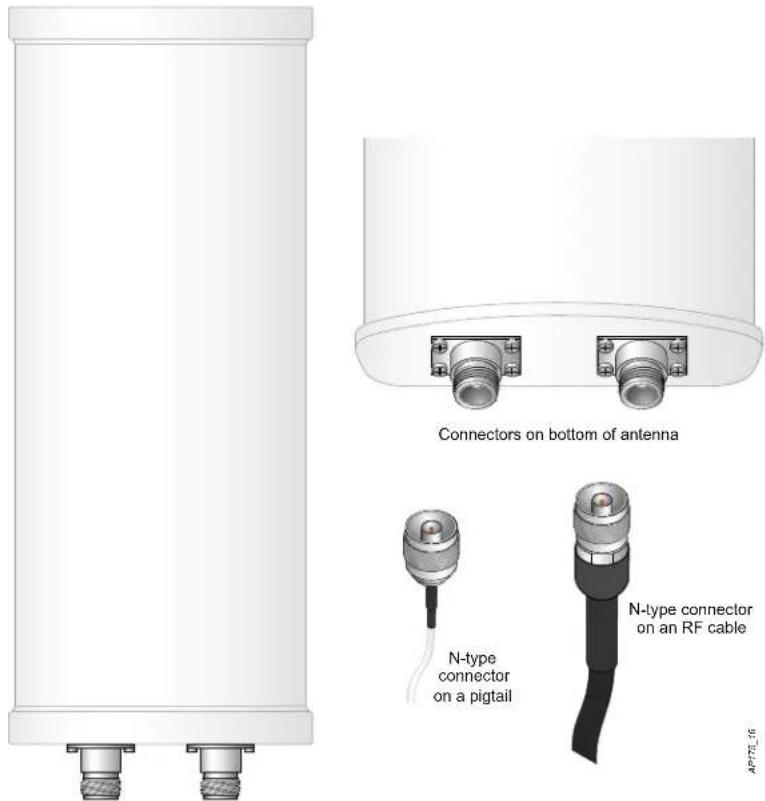
The following sections provide guidance on weatherproofing directly connected antennas (Figure 6) and cable connections (Figure 7). The same materials are needed for weatherproofing both types of connections but the procedure is slightly different. For weatherproofing directly connected antennas, see "Weatherproofing Directly Connected Antennas" on page 14. For weatherproofing cable connections, see "Weatherproofing Cable Connections" on page 17.
Figure 6 Directly Connected Antennas
text_image
Weep holes AP129.11Figure 7 Cable Connections
text_image
Connectors on bottom of antenna N-type connector on a pigtail N-type connector on an RF cableImportant Points to Remember
- Do not cover the weep holes on the antennas. Doing so can restrict the release of condensation from the antennas.
- Proper weatherproofing is not a fast process. Set aside ample time to complete the steps outlined below.
- When wrapping, make the each layer of tape as flat as possible. Wrinkles and folds in the tape create places for water and moisture to gather.
Weatherproofing Directly Connected Antennas
First Wrapping of Tape
- Before wrapping the antennas, locate the weep holes (Figure 6). Weep holes allow condensation that has built up inside the antenna to escape.
- Prepare the antenna connector by cleaning and drying it.
- Cut a 4" (100 mm) strip of electrical tape from the roll. Pre-cutting the tape into strips makes in easier to maneuver the tape around the antennas and other components of the AP's case.
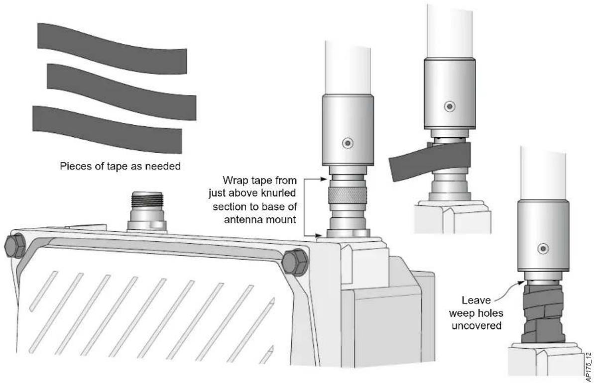
- Beginning just below the weep holes, tightly wrap the connection with a layer of the 3/4" (19mm) electrical tape. Overlap the tape to a half-width.
- Repeat steps 3 and 4 until the wrapping extends all the way to the AP's case.
Figure 8 First Wrapping of Tape
text_image
Pieces of tape as needed Wrap tape from just above knurled section to base of antenna mount Leave weep holes uncovered AP785_12Wrapping of Butyl Rubber
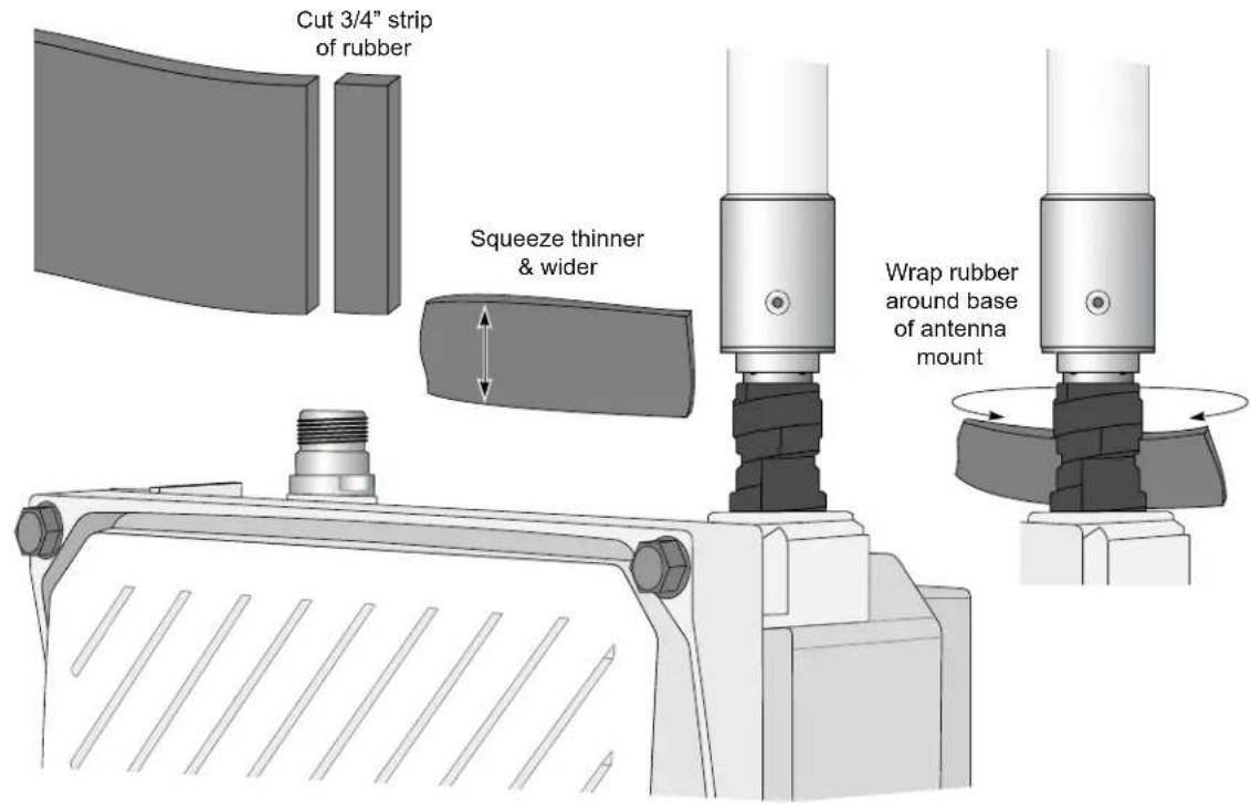
- Cut a 3/4" (19 mm) strip of butyl rubber.
- Wrap the strip of rubber around the taped connector (Figure 9)
- Join the two ends by pushing them together until there is no longer a seam (Figure 10).
Figure 9 Butyl Rubber Placement
text_image
Cut 3/4" strip of rubber Squeeze thinner & wider Wrap rubber around base of antenna mountFigure 10 Butyl Rubber Wrap
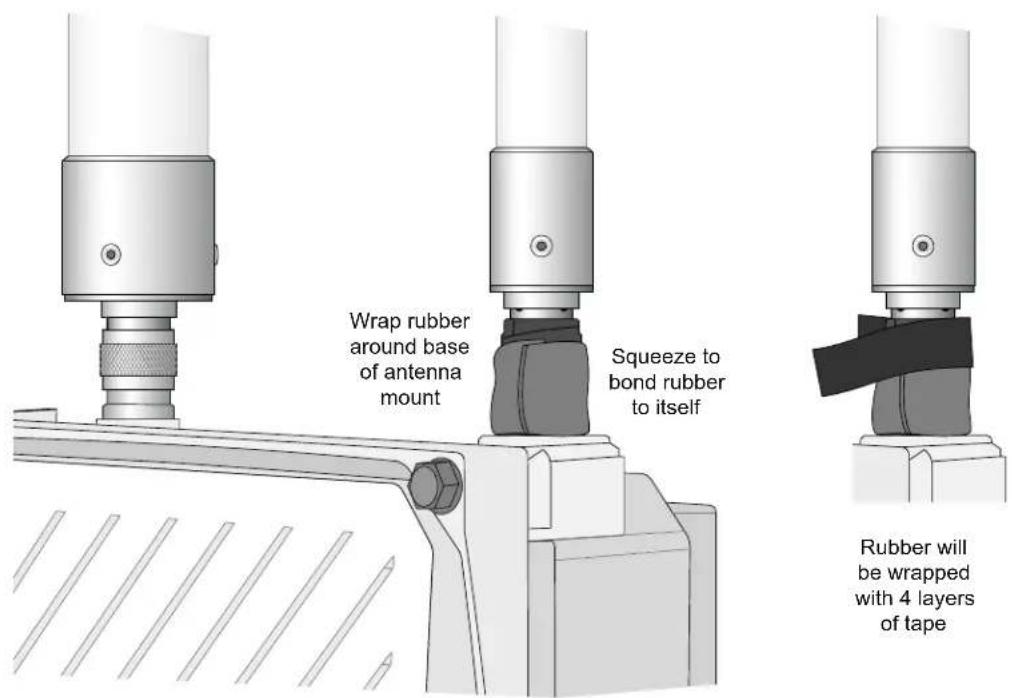
text_image
Wrap rubber around base of antenna mount Squeeze to bond rubber to itself Rubber will be wrapped with 4 layers of tapeAP175_14
Second Wrapping of Tape
- Cut a 4" (100 mm) strip of electrical tape from the roll.
- Where you begin wrapping depends on the orientation of the antenna. Water should flow in the opposite direction of the wrapping to prevent water from entering the connector between the layers of tape.
Therefore, if the antenna is facing up, you should begin wrapping at the AP end of the connector. This will ensure that your fourth and final layer will be layered correctly. Conversely, if your antenna is facing down, you should begin wrapping on the antenna end of the connector. - After completing the fourth layer of tape, check your work to ensure there are no places where water can collect. If there are, you must smooth out those areas with additional layers of tape or remove the weatherproofing and begin again.
Figure 11 Completed Wrapping (Antenna on Top of AP)
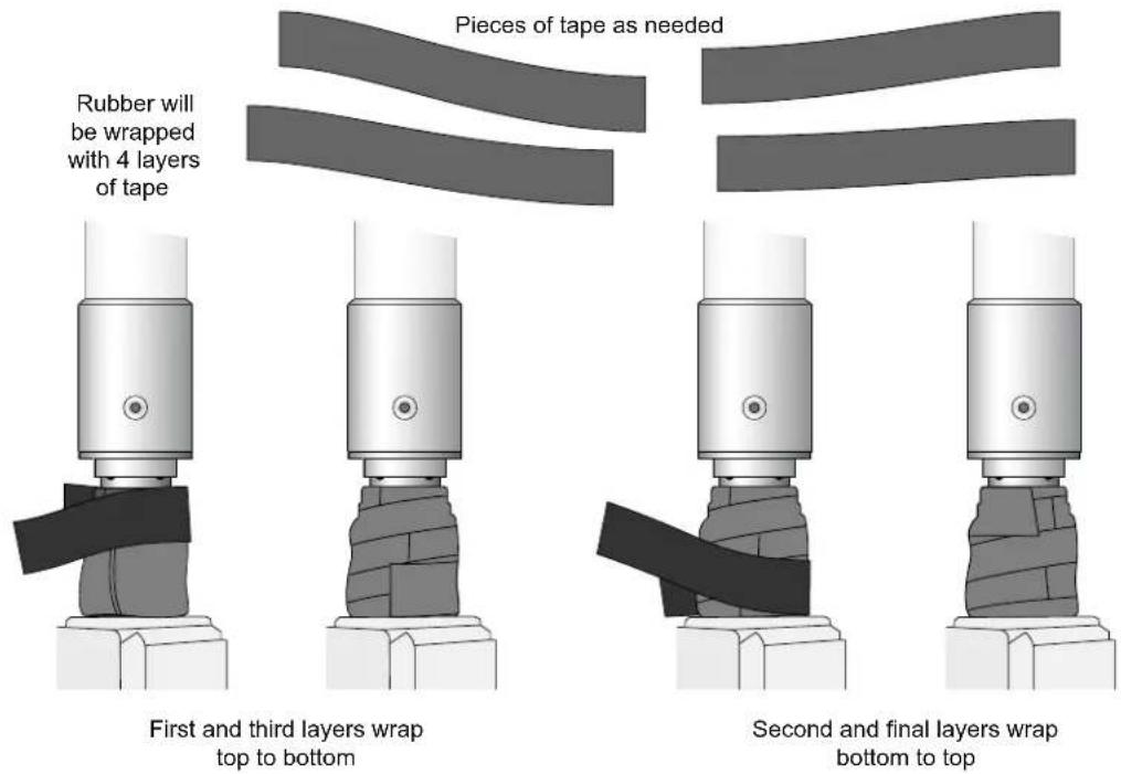
text_image
Pieces of tape as needed Rubber will be wrapped with 4 layers of tape First and third layers wrap top to bottom Second and final layers wrap bottom to top- Repeat this process for all connectors.
Weatherproofing Cable Connections
First Wrapping of Tape
- Prepare the antenna connector by cleaning and drying it.
- Cut a 4" (100 mm) strip of electrical tape from the roll. Pre-cutting the tape into strips makes in easier to maneuver the tape around the connectors and other components but is not required.
- Beginning at the top of the connector, tightly wrap the connection with a layer of the 3/4" (19mm) electrical tape. Overlap the tape to a half-width.
- Repeat steps 3 and 4 until the wrapping extends all the way to the cable's insulation.
Figure 12 First Wrapping of Tape
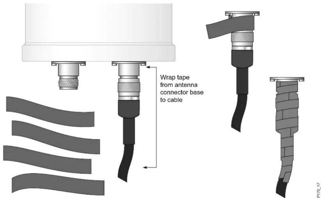
text_image
Wrap tape from antenna connector base to cablePieces of tape as needed
Wrapping of Butyl Rubber
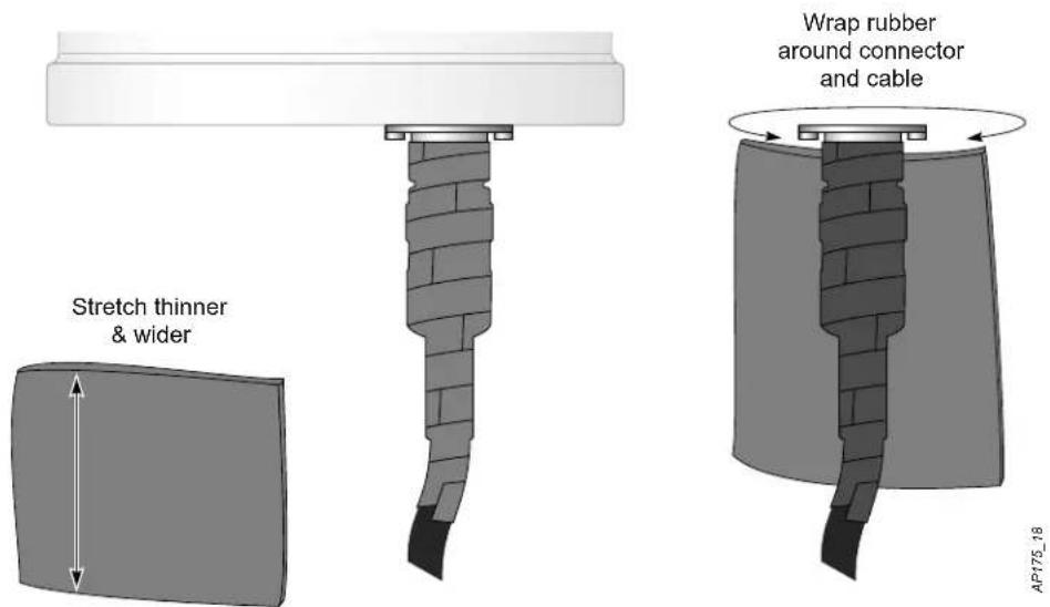
- Cut a piece of butyl rubber large enough to wrap around the connector and extended past the first layer of tape.
- Wrap the strip of rubber around the taped connector (Figure 13)
- Join the two ends by pushing them together until there is no longer a seam (Figure 14).
Figure 13 Butyl Rubber Placement
text_image
Stretch thinner & wider Wrap rubber around connector and cable AP175_18Figure 14 Butyl Rubber Wrap
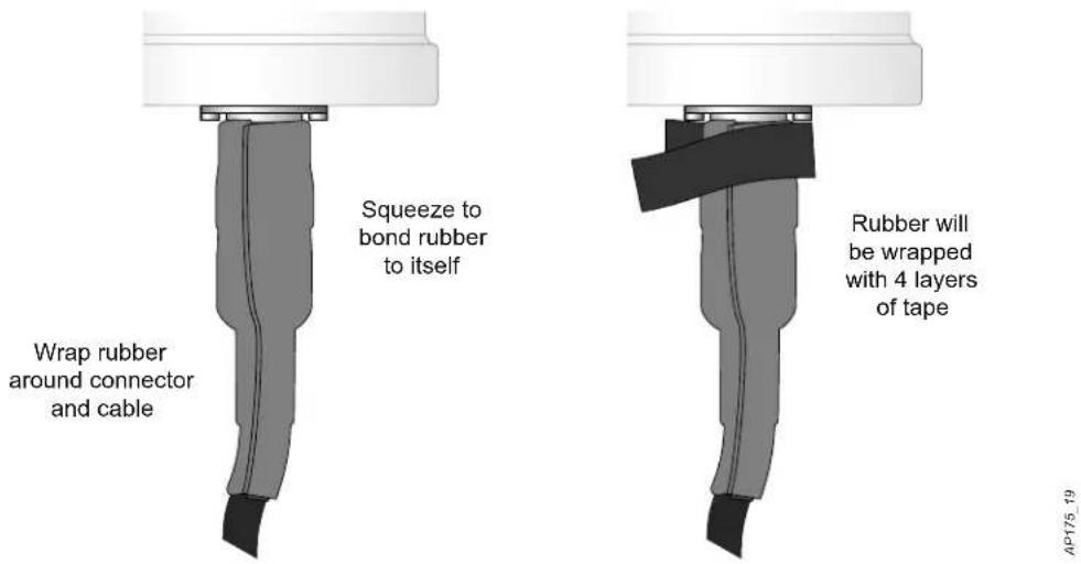
text_image
Squeeze to bond rubber to itself Wrap rubber around connector and cable Rubber will be wrapped with 4 layers of tape AP175.19Second Wrapping of Tape
- Cut a 4" (100 mm) strip of electrical tape from the roll.
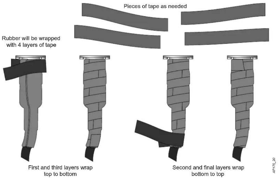
- Using 3/4" (19mm) electrical tape, begin wrapping at the connector and create four layers.
- After completing the fourth layer of tape, check your work to ensure there are no places where water can collect. If there are, you must smooth out those areas with additional layers of tape or remove the weatherproofing and begin again.
Figure 15 Completed Wrapping
text_image
Pieces of tape as needed Rubber will be wrapped with 4 layers of tape First and third layers wrap top to bottom Second and final layers wrap bottom to top AP175_20- Repeat this process for all connectors.
Installing the IAP-175
The IAP-175 can be installed on a wall or attached to a pole. The following section describes how to attach the necessary hardware to the AP and how to mount the AP in the selected location.

Service to all Aruba products should be performed by trained service personnel only.

Access points are radio transition devices and as such are subject to governmental regulation. Network administrators responsible for the configuration and operation of access points must comply with local broadcast regulations. Specifically, access points must use channel assignments appropriate to the location in which the access point will be used and comply with regulatory requirements for Outdoor intentional radiators.
Selecting the Installation Site
- The site should be located within at least a 60% range of the 1st fresnel zone without obstacles to provide line of sight (LOS) transmission, increase coverage capacity, and minimize the number of necessary sites.
- If no LOS is secured, areas in non-line-of-sight (NLOS) areas could be covered as well, but the distance of coverage and area of coverage are decreased; more sites are needed to provide coverage for same area than in the LOS scenario.
- Interference must be considered in site selection. The new site should avoid known interference, unless the interference is controllable.
- Keep the IAP-175 away from places that are susceptible to high temperature, dust, harmful gas, inflammable, explosive, electromagnetic interference (high power radar, radio station and transformer), unstable voltage, heavy vibration, or loud noise. In engineering design, the site should be selected according to the network planning and technical requirements of communications equipment, as well as the considerations such as climate, hydrology, geology, earthquake, electric power, and transportation.
Installing the IAP-175 on a Pole
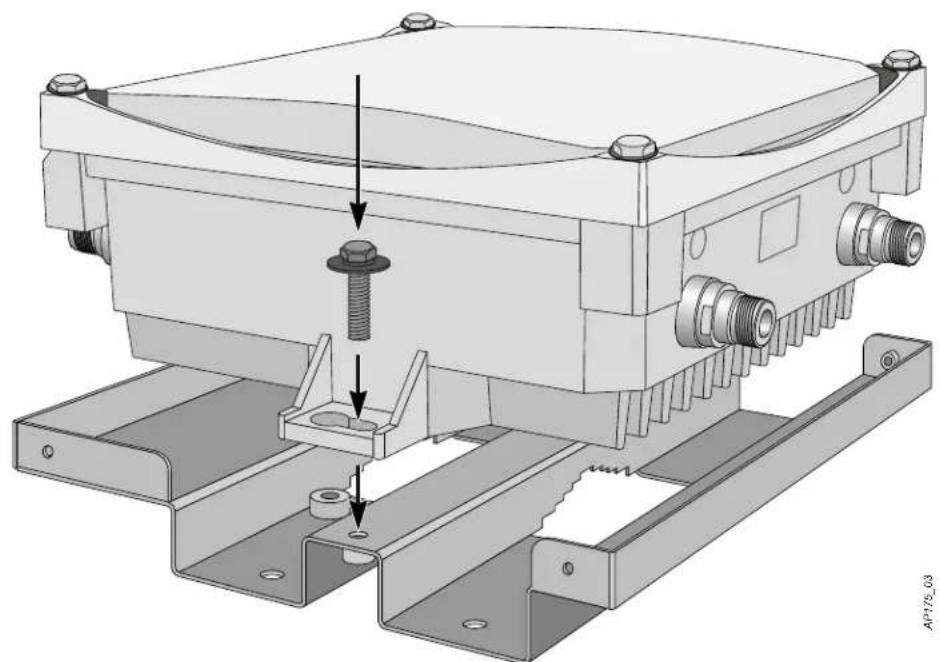
- Attach the IAP-175 on the mounting bracket using the two M6 x30 bolts (with flat and spring washers) on each side of the mounting bracket.
Figure 16 Attaching the mounting bracket to the AP
natural_image
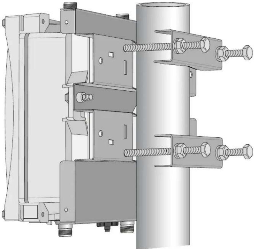
Technical illustration of a mechanical assembly with mounting brackets and a central screw (no text or symbols)- Attach the mounting bracket (with IAP-175) on the pole using four M8 x110 bolts (with flat washers, spring washers and nuts) and the pair of pole anchors.
Figure 17 Attaching the mounting bracket to the pole
natural_image
Technical illustration of a mechanical assembly with bolts and mounting brackets (no text or symbols)Installing the IAP-175 on a Wall
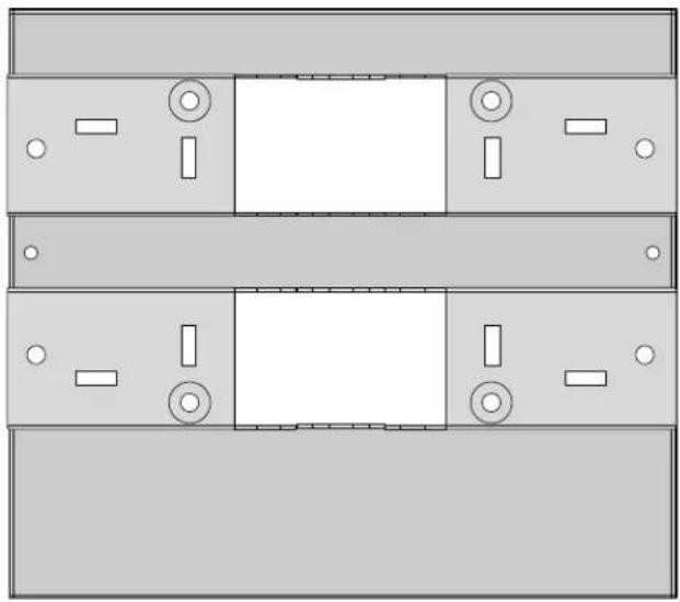
- Begin by marking the screw points on the wall in the location you have selected.
a. Put the mounting bracket on the installation position against the wall.
b. Mark four expansion screw holes on the wall.
Figure 18 Position of the screw holes
natural_image
Pure diagram of three identical rectangular panels with internal compartments and circular elements, no text or symbols present.-
Use a drill to create four holes on the four markings you created in the previous step.
-
Install wall (masonry) anchors.
a. Insert a masonry anchor into each drilled hole.
b. Tap the flat end of the anchor with a rubber hammer until the anchor is flush with the wall surface.
- Attach the mounting bracket to the wall.
a. Align the four holes in the mounting bracket with the anchors and insert four expansion screws through the installation holes into the anchors.
b. Adjust the position of the mounting bracket and tighten the expansion screws.
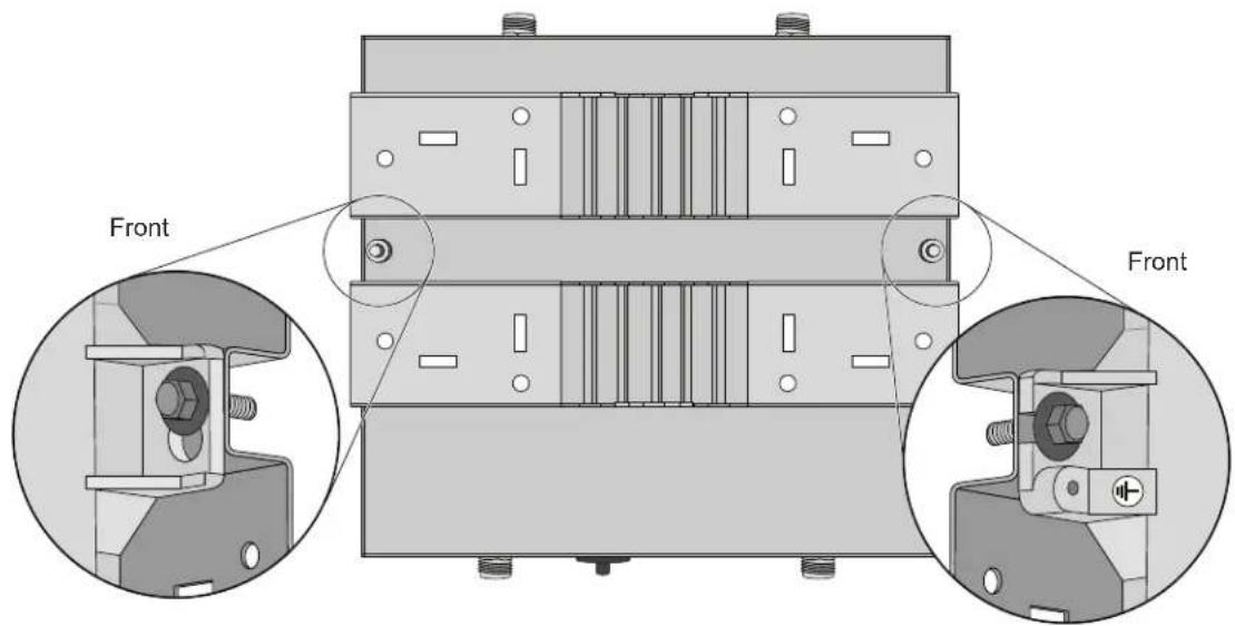
- Attach the IAP-175 to the mounting bracket by inserting the two M6 x30 bolts (with flat and spring washers) through the installation holes, and tighten the bolts.
Figure 19 Attaching the AP to the Mounting Bracket
text_image
Front FrontGrounding the IAP-175
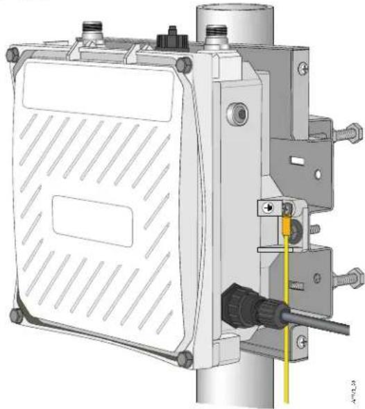
The grounding must be completed before powering up the IAP-175. The resistance of grounding wire should be less than 5 ohm and the grounding cable's cross-section area should be no less than 6 mm. The grounding hole is at the right side of the IAP-175.
Figure 20 Grounding the IAP-175
natural_image
Technical illustration of a mechanical device with mounting bracket and yellow cable (no text or symbols)-
Peel the cover of one end of the grounding cable (green or yellow and green grounding cable with 6 mm cross-section area) and place the bare grounding cable into the copper lug, and press firmly with the crimping pliers.
-
Fasten the copper lug to the grounding hole on the IAP-175 with the M4 x12 bolt and external-tooth washer.
Connecting the Ethernet Cable (IAP-175P)
To ensure that your outdoor access point (AP) maintains Ethernet connectivity and Power over Ethernet (PoE), you must use the included weatherproof connector kit and install it using the steps below.

Failure to use the included weatherproof connector kit can lead to connectivity and PoE issues.
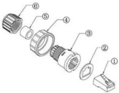
Figure 21 Waterproof Ethernet Connector Cover
text_image
Exploded view diagram of a mechanical connector with numbered parts for identification| 1 Shielded RJ45 connector 4 Locknut | ||
| 2 G a s k e t M a t 5 | S | e a l R i n g |
| 3 W | Waterproof Connector Socket 6 Sealing Nut |
- Remove the cover from the adhesive side of the gasket mat and place it over the weatherproof connector socket.
- Place the locknut over the weatherproof connector socket.
- Place the sealing nut over an ethernet cable (without a connector attached to the end).
- Place the seal ring over the ethernet cable.
- Insert the ethernet cable into the narrow end of the weatherproof connector socket and pass it through the opening on the wide end.
- Using a crimping tool, attach the included shielded RJ45 connector.
- Slide the seal ring up the ethernet cable and insert it into the narrow end of the weatherproof connector socket.
- Pull the ethernet cable so the shielded RJ45 connector fits into the RJ45 shaped opening in the wide end of the weatherproof connector socket.
- Slide the sealing nut over the narrow end of the weatherproof connector socket and hand tighten it.
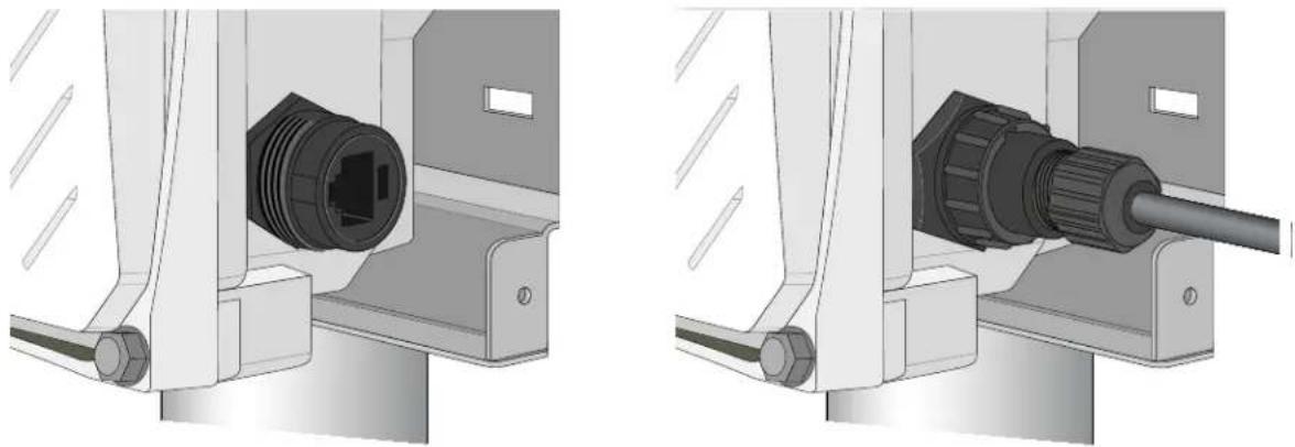
- Insert the ethernet cable connector into the Ethernet interface and hand-tighten the locknut.
- Water-proof the Ethernet cable connection with electrical tape and butyl rubber.
Connecting the Ethernet Cable (IAP-175AC)
To ensure that your outdoor access point (AP) maintains Ethernet connectivity and Power over Ethernet (PoE), you must use the included weatherproof connector kit and install it using the steps below.

Failure to use the included weatherproof connector kit can lead to connectivity and PoE issues.
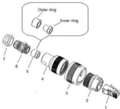
Figure 22 Waterproof Ethernet Connector Cover
text_image
Outer ring Inner ring 1 2 3 4 5 6 7| 1 Shielded RJ45 connector 5 Shield rings | ||
| 2 Waterproof Connector Socket 6 Sealing Bolt | ||
| 3 Locknut 7 Sealing Nut | ||
| 4 Clamp ring |
- Hold the clamp ring (4) vertically, with the wide end facing up, and place the locknut (3) over it.
- Drop the waterproof connector socket (2) into the locknut/clamp ring items (3,4), with the RJ45 connector opening facing up, and screw the socket into the threads on the clamp ring.
- Place the sealing nut (7) over an Ethernet cable (without a connector attached to the end).
- Place the seal bolt (6) over the Ethernet cable.
- Strip off about 55mm (2 inches) of the outer Ethernet cable sheath to expose the ground wire and other pair wires.
- Insert all pair wires into the two shield rings (5).
- Make the ground wire attach to the narrow end of the inner ring and place the outer ring over the narrow end of the inner ring.
- Insert the Ethernet cable into the narrow end of the clamp ring and pass it through the opening end of waterproof connector socket.
- Using a crimping tool, attach the included shielded RJ45 connector.
- Slide the shield rings up the Ethernet cable and insert it into the narrow end of the clamp ring.
- Pull the Ethernet cable so the shielded RJ45 connector fits into the RJ45 shaped opening in the wide end of the weatherproof connector socket.
- Slide the sealing bolt over the narrow end of the clamp ring and hand tighten it.
- Thread the sealing nut onto the sealing bolt.
- Insert the Ethernet cable connector into the Ethernet interface and hand-tighten the locknut.
- Water-proof the Ethernet cable connection with electrical tape and butyl rubber.
Figure 23 Connecting the Ethernet cable
natural_image
Technical illustration of two mechanical assembly setups showing a connector inserted into a housing (no text or symbols present)Connecting the Power Cable (AP-175 AC)

Installation and service of Aruba products should be performed by Professional Installers in a manner that is consistent with the electrical code in force in the jurisdiction of deployment. In many countries this will require a licensed electrician to perform this operation. In Japan, this is a Certified Electrician by Ministry of Economy, Trade, and Industry.
The best practice is to connect to AC mains in an outdoor grade weather protected junction box.
The use of plugs with infrastructure equipment is suitable only for temporary installs where nuisance tripping of GFCI plugs is considered tolerable. Should it be required to attach a plug to the cable assemblies, the installer is must follow all directions provided with the plug end in a fashion consistent with local electrical code.
Use of CKIT-AC-M
CKIT-AC-M is a weatherproof connector kit for an AC power interface. Assembly instructions for this part are shipped with the part. All instructions must be followed to ensure proper assembly of the connector onto the cable. The required specifications for third party AC power cable used with the CKIT solution are as follows:
• 250V/1A minimum voltage/current rating
- 6-12mm diameter
• rated for outdoor use and UV exposure
Figure 24 AC Power Connector PIN OUT on the AP-175AC

text_image
Neutral Live Earth Power Interface on AP 1.7mm Live Neutral 30mm Earth AC Power Cable ConnectorAttaching the Solar Shield to the IAP-175
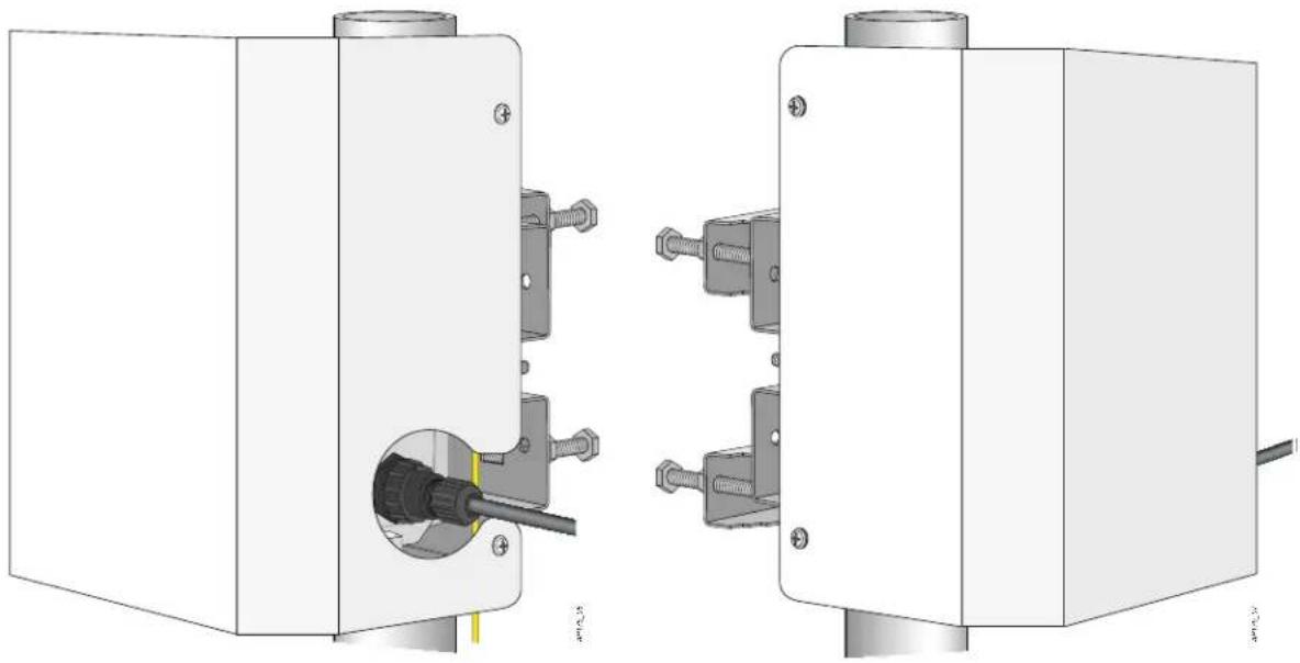
Attach the solar shield to the IAP-175 by using the four M4 x16 (with flat and spring washers).
Figure 25 Attaching the Solar Shield to the AP
natural_image
Technical diagram showing two mechanical components with connectors and a central connector (no text or symbols present)Product Specifications
Mechanical
• Dimensions (H x W x D)
■ 10.2 inches x 9.4 inches x 4.1 inches
■ 26 cm x 24 cm x 10.5 cm
• Weight: 7 lbs/3.25 kg
• Shipping Dimensions (H x W x D)
■ 12.9 inches x 12.6 inches x 11.8 inches
■ 33 cm x 32 cm x 30 cm
• Shipping Weight: 16.6 lbs/7.5 kg
- Temperature
■ Operating (IAP-175P): -30°C to 60°C (-22°F to 140°F)
■ Operating (IAP-175AC): -40°C to 55°C (-40°F to 131°F)
■ Storage: -40^ to 70^ ( -40^ to 158^ )
• Relative Humidity: 5% to 95% non-condensing
• Altitude: Up to 9,850ft (3,000 meters)
- Mounting: wall or pole mountable
- Antennas:
- Quad, N-type female interfaces (2 x 2.4 GHz, 2 x 5GHz) for external antenna support (supports MIMO)
■ Feeder cable may be used for external antenna deployments
• Visual Status Indicators (LEDs): See Table 2
Electrical
Power In
- IAP-175P: 48-volt DC 802.3at power over Ethernet (PoE+)
- IAP-175AC: 100-240 volt AC from external AC power source
- Maximum power consumption: 18 watts (excludes power consumed by any POE device connected to and powered by the IAP-175AC)
Power Out
- The AC powered models provide an 802.3af POE power source (PSE) on the Ethernet interface.
Interfaces
- Network:
■ 1 x 10/100/1000BASE-T Ethernet (RJ-45), auto-sensing link speed and MDI/MDX
Power:
■ 1 x AC power connector (in IAP-175AC model only)
- Antenna:
■ 4 x N-Type female antenna interfaces
- Other:
■ 1 x USB console interface
Wireless LAN
• AP type: Dual-radio, dual-band 802.11n outdoor
- Supported frequency bands (country-specific restrictions apply):
■ 2.400 to 2.4835 GHz
5.150 to 5.250 GHz
5.250 to 5.350 GHz
5.470 to 5.725 GHz
5.725 to 5.850 GHz
• Available channels: Virtual controller-managed, dependent upon configured regulatory domain
• Supported radio technologies:
■ 802.11b: Direct-sequence spread-spectrum (DSSS)
■ 802.11a/g/n: Orthogonal frequency division multiplexing (OFDM)
■ 802.11n: 2x2 MIMO with two spatial streams
• Supported modulation types:
■ 802.11b: BPSK, QPSK, CCK
■ 802.11a/g/n: BPSK, QPSK, 16-QAM, 64-QAM
- Transmit power: Configurable in increments of 0.5 dBm
• Maximum transmit power:
■ 2.4 GHz: 25 dBm (limited by local regulatory requirements)
■ 5 GHz: 25 dBm (limited by local regulatory requirements)
• Maximum ratio combining (MRC) for improved receiver performance
• Association rates (Mbps):
■ 802.11b: 1, 2, 5.5, 11
■ 802.11a/g: 6, 9, 12, 18, 24, 36, 48, 54
■ 802.11n: MCS0 - MCS15 (6.5 Mbps to 300 Mbps)
• 802.11n high-throughput (HT) support: HT 20/40
• 802.11n packet aggregation: A-MPDU, A-MSDU
Safety and Regulatory Compliance
Aruba Networks provides a multi-language document that contains country-specific restrictions and additional safety and regulatory information for all Aruba access points. This document can be viewed or downloaded from the following location: www.arubanetworks.com/safety_addendum

RF Radiation Exposure Statement: This equipment complies with FCC RF radiation exposure limits. This equipment should be installed and operated with a minimum distance of 13.78 inches (35 cm) between the radiator and your body for 2.4 GHz and 5 GHz operations. This transmitter must not be co-located or operating in conjunction with any other antenna or transmitter.

Aruba Access Points and the AP-LAR-1 lightning arrestor are required to be installed by a professional installer. The professional installer is responsible for ensuring that grounding is available and it meets applicable local and national electrical codes.

Do not work on an AP and do not connect or disconnect cables during periods of lightning activity.
FCC
The device is electronically labeled and the FCC ID is displayed via the WebUI under the About menu.
This equipment has been tested and found to comply with the limits for a Class B digital device, pursuant to part 15 of the FCC Rules. These limits are designed to provide reasonable protection against harmful interference in a residential installation. This equipment generates, uses and can radiate radio frequency energy and, if not installed and used in accordance with the instructions, may cause harmful interference to radio communications. However, there is no guarantee that interference will not occur in a particular installation. If this equipment does cause harmful interference to radio or television reception, which can be determined by turning the equipment off and on, the user is encouraged to try to correct the interference by one or more of the following measures:
• Reorient or relocate the receiving antenna.
- Increase the separation between the equipment and receiver.
- Connect the equipment into an outlet on a circuit different from that to which the receiver is connected.
- Consult the dealer or an experienced radio/ TV technician for help.
For a complete list of Country Specific Regulations please speak with your Aruba Representative.
EU Statement
Lower power radio LAN product operating in 2.4 GHz and 5 GHz bands. Please refer to the ArubaOS User Guide for details on restrictions.
Proper Disposal of Aruba Equipment
For the most current information about Global Environmental Compliance and Aruba products, see our website at www.arubanetworks.com.
Waste of Electrical and Electronic Equipment
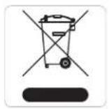
Aruba products at end of life are subject to separate collection and treatment in the EU Member States, Norway, and Switzerland and therefore are marked with the symbol shown at the left (crossed-out wheelie bin). The treatment applied at end of life of these products in these countries shall comply with the applicable national laws of countries implementing Directive 2002/96EC on Waste of Electrical and Electronic Equipment (WEEE).
European Union RoHS
RoHS
Aruba products also comply with the EU Restriction of Hazardous Substances Directive 2002/95/EC (RoHS). EU RoHS restricts the use of specific hazardous materials in the manufacture of electrical and electronic equipment. Specifically, restricted materials under the RoHS Directive are Lead (including Solder used in printed circuit assemblies), Cadmium, Mercury, Hexavalent Chromium, and Bromine. Some Aruba products are subject to the exemptions listed in RoHS Directive Annex 7 (Lead in solder used in printed circuit assemblies). Products and packaging will be marked with the "RoHS" label shown at the left indicating conformance to this Directive.
China RoHS
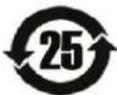
Aruba products also comply with China environmental declaration requirements and are labeled with the "EFUP 25" label shown at the left.
| 有毒有害物質聲明Hazardous Materials Declaration | ||||||
| 部件名称(Parts) | 有毒有害物質或元素(Hazardous Substances) | |||||
| 铅Lead(Pb) | 汞Mercury(Hg) | 镉Cadmium(Cd) | 六价铬Chromium VI Compounds(Cr6+) | 多溴联苯Polybrominated Biphenyls(PBB) | 多溴二苯醚Polybrominated Diphenyl Ether(PBDE) | |
| 电路板PCA Board | O | O | O | O | O | O |
| 机械组件Mechanical Subassembly | X | O | O | O | O | O |
| O:表示该有毒有害物质在该部件所有均质材料中的含量均在SJ/T11363-2006标准规定的限量要求以下。This component does not contain this hazardous substance above the maximum concentration values in homogeneous materials specified in the SJ/T11363-2006 Industry Standard. | ||||||
| X:表示该有毒有害物质至少在该部件的某一均质材料中的含量超出SJ/T11363-2006标准规定的限量要求。This component does contain this hazardous substance above the maximum concentration values in homogeneous materials specified in the SJ/T11363-2006 Industry Standard. | ||||||
| 对销售之日的所售产品,本表显示,供应链的电子信息产品可能包含这些物质。This table shows where these substances may be found in the supply chain of electronic information products, as of the date of sale of the enclosed product. | ||||||
| 此标志为针对所涉及产品的环保使用期标志。某些零部件会有一个不同的环保使用期(例如,电池单元模块)贴在其产品上,此环保使用期限只适用于产品是在产品手册中所规定的条件下工作。The Environment-Friendly Use Period (EFUP) for all enclosed products and their parts are per the symbol shown here. The Enviro nment-Friendly Use Period is valid only when the product is operated under the conditions defined in the product manual. | ||||||
Canada RF Compliance
This Class B digital apparatus complies with Canadian ICES-003.
This device complies with RSS 210 of Industry Canada.
Operation is subject to the following two conditions: (1) this device may not cause interference, and (2) this device must accept any interference, including interference that may cause undesired operation of this device.
High power radars are allocated as primary users of the 5.25 to 5.35 GHz and 5.47 to 5.6 GHz and 5.65 to 5.725 GHz bands. These radar stations can cause interference with and/or damage this device.
This device will not operate on channels which overlap the 5600 - 5650 MHz band.
This device must not be co-located or operated in conjunction with any other unauthorized antenna or transmitter.
This equipment complies with IC radiation exposure limits and should be installed and operated with minimum distance 20cm between the radiator and your body.
Complies with IDA Standards 200202320G
This page is intentionally left blank.
This page is intentionally left blank.
This page is intentionally left blank.
Contacting Aruba Networks
| Web Site Support | |
| Main Site http://www.arubanetworks.com | |
| Support Site https://support.arubanetworks.com | |
| Software Licensing Site | https://licensing.arubanetworks.com/login.php |
| Wireless Security Incident Response Team (WSIRT) | http://www.arubanetworks.com/support/wsirt.php |
| Support Emails | |
| • Americas and APAC | support@arubanetworks.com |
| • EMEA emea.support@arubanetworks.com | |
| WSIRT Email Please email details of any security problem found in an Aruba product. | wsirt@arubanetworks.com |
| Telephone Support | |
| Aruba Corporate +1 (408) 227-4500 | |
| FAX +1 (408) 227-4550 | |
| Support | |
| United States 800-WI-FI-LAN (800-943-4526) | |
| Universal Free Phone Service Number (UIFN): Australia, Canada, China, France, Germany, Hong Kong, Ireland, Israel, Japan, Korea, Singapore, South Africa, Taiwan, and the UK. | +800-4WIFI-LAN (+800-49434-526) |
| All Other Countries +1 (408) 754-1200 | |
Copyright
© 2012 Aruba Networks, Inc. AirWave®, Aruba Networks®, Aruba Mobility Management System®, Bluescanner, For Wireless That Works®, Mobile Edge Architecture, People Move. Networks Must Follow., RFprotect®, The All Wireless Workplace Is Now Open For Business, and The Mobile Edge Company® are trademarks of Aruba Networks, Inc. All rights reserved. All other trademarks are the property of their respective owners.
Open Source Code
Certain Aruba products include Open Source software code developed by third parties, including software code subject to the GNU General Public License (GPL), GNU Lesser General Public License (LGPL), or other Open Source Licenses. The Open Source code used can be found at this site:
http://www.arubanetworks.com/open_source
Legal Notice
The use of Aruba Networks, Inc. switching platforms and software, by all individuals or corporations, to terminate other vendors' VPN client devices constitutes complete acceptance of liability by that individual or corporation for this action and indemnifies, in full, Aruba Networks, Inc. from any and all legal actions that might be taken against it with respect to infringement of copyright on behalf of those vendors.
Warranty
This hardware product is protected by the standard Aruba warranty of one year parts/labor. For more information, refer to the ARUBACARE SERVICE AND SUPPORT TERMS AND CONDITIONS.
Altering this device (such as painting it) voids the warranty.

networks
www.arubanetworks.com
1344 Crossman Avenue
Sunnyvale, California 94089
Phone: 408.227.4500
Fax 408.227.4550