
AutoDome VG4-324 - Security Camera BOSCH - Free user manual and instructions
Find the device manual for free AutoDome VG4-324 BOSCH in PDF.


User questions about AutoDome VG4-324 BOSCH
0 question about this device. Answer the ones you know or ask your own.
Ask a new question about this device
Download the instructions for your Security Camera in PDF format for free! Find your manual AutoDome VG4-324 - BOSCH and take your electronic device back in hand. On this page are published all the documents necessary for the use of your device. AutoDome VG4-324 by BOSCH.
USER MANUAL AutoDome VG4-324 BOSCH
natural_image
Four white security cameras with visible sensor heads and a wall-mounted cable (no text or symbols)VG4 Modular Camera System
VG4-200 | VG4-300 | VG4-500i

BOSCH
en User's Manual
Table of Contents
1 Getting Started 7
1.1 Powering On 7
1.2 Establishing AutoDome Control 7
1.2.1 Basic Keyboard Operation 7
1.2.2 Keyboard Commands 8
1.3 Setting the Camera Address 8
1.3.1 FastAddress 9
1.4 Setting Passwords 9
1.4.1 Special Passwords 9
2 On-Screen Display Menu Navigation 11
2.1 Setup Menu 11
2.2 Camera Setup Menu 12
2.3 Lens Setup 14
2.4 PTZ Setup Menu 16
2.5 Display Setup Menu 17
2.6 Communication Setup Menu 19
2.7 Alarm I/O Setup 20
2.8 Rule Setup Menu 23
2.9 Language Menu 24
2.10 Advanced Feature Setup Menu (available with Series 500i only) 25
2.11 Diagnostics Menu 26
2.11.1 Alarm Status Submenu 28
3 Common AutoDome User Commands (unlocked) 30
3.1 Setting AutoPan Mode 30
3.2 Setting Preset Shots 30
3.3 Specifying a Shot or a Sector Title 30
3.4 Configuring Preposition Tours 31
3.5 Programming the Inactivity Operation 31
3.6 Recording Tours (300 and 500i Series only) 32
4 Alternative Control Protocols 33
4.1 Setting FastAddress with Alternative Protocols 33
4.1.1 Using an American Dynamics Controller 33
4.1.2 Using a Pelco Controller 35
4.2 Pelco Protocol Mode 36
4.2.1 Hardware Configuration 36
4.2.2 Pelco Keyboard Commands 37
4.2.3 Pelco Keyboard Commands 37
4.2.4 Special Preset Commands 38
5 Pelco On-Screen Menus 39
5.1 Setup Menu 39
5.1.1 Command Lock (locked) 40
5.1.2 Bosch Menu (locked) 40
5.1.3 PTZ Setup (unlocked) 41
5.1.4 Other Menus 42
6 Keyboard Commands by Number 43
7 Advanced Features 46
7.1 Alarm Rules (300 and 500i Series Only) 46
7.1.1 Controlling Alarm Rules 46
7.1.2 Alarm Rule Examples 46
7.2 AutoTrack Operation (500i Series Only) 50
7.2.1 AutoTrack Settings and Recommendations 50
7.2.2 AutoTrack Optimization 51
7.3 Virtual Masking (500i Series Only) 52
7.4 Privacy Masking (300 and 500i Series Only) 52
7.5 Motion Detection with Region of Interest (500i Series Only)
(Preset positions 90 through 99)53
7.6 Image Stabilization (500i Series Only) 53
7.7 Pre-position Tour 53
8 Using the IP AutoDome 55
8.1 Overview of Features 55
8.2 System Requirements 55
8.3 Connecting the IP AutoDome to the PC 56
8.4 Configuring the IP AutoDome Camera 57
8.5 Installing the Required Software 57
8.5.1 Changing the Network Settings 58
8.6 The LIVEPAGE 60
8.6.1 Entering a Keyboard Control Command 62
8.7 Saving Snapshots 64
8.8 Recording Video Sequences 64
8.9 Running Recording Program 64
9 VG4 Audio Connections 65
9.1 Audio Line Input Specifications 65
9.1.1 Wire Specifications 65
9.1.2 Connections 65
9.1.3 Activating Audio Reception 65
9.1.4 Enabling Audio Transmission 66
9.1.5 Configuring Gain (optional) 67
10 Configuring the IP AutoDome 68
10.1 Basic Mode: Device Access 68
10.2 Basic Mode: Date/Time 69
10.3 Basic Mode: Network 70
10.4 Basic Mode: Encoder Profile 71
10.5 Basic Mode: Audio 71
10.6 Basic Mode: Recording 71
10.7 Basic Mode: System Overview 72
10.8 Advanced Mode: Identification 72
10.9 Advanced Mode: Password 73
10.10 Advanced Mode: Date/Time 73
10.11 Advanced Mode: Display Stamping 74
10.12 Advanced Mode: Appearance 75
10.13 Advanced Mode: LIVEPAGE Functions 76
10.14 Advanced Mode: Logging 77
10.15 Advanced Mode: Picture Settings 77
10.16 Advanced Mode: Encoder Profile 78
10.17 Advanced Mode: Encoder Streams 80
10.18 Advanced Mode: Audio 80
10.19 Advanced Mode: Camera Options 81
10.20 Camera Settings Group 1 81
10.21 Camera Settings Group 2 82
10.22 Camera Settings Group 3 82
10.23 Advanced Mode: Lens 82
10.24 Lens Settings Group 1 82
10.25 Lens Settings Group 2 83
10.26 Advanced Mode: PTZ 83
10.27 PTZ Settings Group 1 83
10.28 PTZ Settings Group 2 84
10.29 Advanced Mode: Display 85
10.30 Display Settings Group 1 85
10.31 Display Settings Group 2 85
10.32 Display Settings Group 3 86
10.33 Advanced Mode: Alarm 86
10.34 Input Options 86
10.35 Output Options 87
10.36 Alarm Rules 88
10.37 Miscellaneous 93
10.38 Logs 94
10.39 Advanced Mode: Storage Management 94
10.40 Advanced Mode: Recording Profiles 95
10.41 Advanced Mode: Retention Time 97
10.42 Advanced Mode: Recording Scheduler 97
10.43 Advanced Mode: Recording Status 98
10.44 Advanced Mode: Alarm Connections 99
10.45 Advanced Mode: VCA 101
10.46 Advanced Mode: VCA Profiles 101
10.47 Advanced Mode: VCA Scheduled 105
10.48 Advanced Mode: VCA Event triggered 106
6 en | Table of Contents VG4 Modular Camera System
10.49 Advanced Mode: Audio Alarm 107
10.50 Advanced Mode: Alarm E-Mail 107
10.51 Advanced Mode: Alarm Task Editor 108
10.52 Advanced Mode: Network 110
10.53 Advanced Mode: Advanced 112
10.54 Advanced Mode: Multicasting 113
10.55 Advanced Mode: JPEG Posting 114
10.56 Advanced Mode: Encryption 115
10.57 Advanced Mode: Maintenance 115
10.58 Advanced Mode: Licenses 116
10.59 Advanced Mode: System Overview 116
11 Troubleshooting Guide 117
11.1 VG4 AutoDome Operation and Control 117
11.2 VG4 IP AutoDome Video and Control 120
11.3 VG4 IP AutoDome Audio 121
12 User Command Table 125
A Appendix: FastAddress Conversions 127
Index 128
1 Getting Started
Install and wire the AutoDome according to the Bosch AutoDome Modular Camera System Installation Manual. A typical system includes a keyboard, matrix switcher, monitor, and appropriate wiring connections. Please refer to the individual product manuals for complete installation and setup instructions for each of the system components.
1.1 Powering On
When you turn the AutoDome power on there is a ten (10) second pause before the dome starts its homing phase. During the homing phase the camera pans left and right and tilts up and down. It also adjusts the lens focus. The entire homing phase lasts approximately 40 seconds and ends with a splash screen.
Bosch Security Sys. AutoDome(r)
| 500 Series(P) | 1.10.00.02/1.07.58.02 |
| Day/Night 26X | 2.00.00.00 |
| SC Boot | 1.05.00.01 |
| FPGA | 1.13.01.05 |
| Lang. Table | 1.00.00.01 |
| VCA_boot | 1.02.00.01 |
| IP-Panel | 4.10.50.13 |
| IP Address | 10.25.118.111 |
| Subnet Mask | 255.255.248.0 |
| No Heater |
FastAddress: Not Set
Figure 1.1 Sample VG4 Startup Splash Screen
The splash screen displays the type of AutoDome, the camera installed, the firmware levels for various files, and the current IP address (if the AutoDome contains the IP Communications module). The (P) to the right of the AutoDome series indicates that the AutoDome contains the optional modules for maintaining internal pressure.
1.2 Establishing AutoDome Control
The most common ways to interface with the AutoDome are:
- Using a keyboard and on-screen display (OSD) menus. This method is the most common and is covered in this manual.
- Using the AutoDome Configuration Tool software running on a PC with Bilinx or the RS-232/485 communication protocol. Refer to the CTFID User Manual for instructions.
- Using a PC-based graphical user interface (GUI) such as the Bosch DiBos 8 software. Refer to the DiBos 8 User Guide for instructions.
- Using the Bosch IP Web interface included with the IP Communications Module.
1.2.1 Basic Keyboard Operation
The following tables summarize the basic operations for a standard keyboard and the functions available to control an AutoDome camera.
| Typical Keyboard Features | Usage |
| Function Keys Selects a specific control setting. | |
| Number Keys | Inputs a number from 0 to 9. |
| Camera Key | Selects a camera number. |
| Enter Key | Inputs a selection. |
| Focus Key | Sets the lens focus or makes a menu selection in OSD mode. |
| Iris Key | Sets the lens iris setting or makes a menu selection in OSD mode. |
| Key LEDs | Indicates an active key. |
| LCD | Displays the current status. |
| Joystick | Controls a pan/tilt/zoom (PTZ) AutoDome camera. |
Table 1.1 Typical Keyboard Functions
| Dome Operation | How to control |
| To Pan Side to Side | Move the joystick left or right. |
| To Tilt Up and Down | Move the joystick forward and back. |
| To Zoom In | Twist the joystick clockwise. |
| To Zoom Out | Twist the joystick counterclockwise. |
Table 1.2 Typical Keyboard Controls for an AutoDome Camera
1.2.2 Keyboard Commands
Keyboard control commands are composed of a sequence of three (3) inputs with the following convention: 1) a Function key + 2) a Command number key(s) + 3) the Enter key.
- Depending on the type of keyboard, the control function keys are labeled:
ON or AUX ON
OFF or AUX OFF
SET or SET SHOT
SHOT or SHOW SHOT

NOTICE! The convention used for control key commands in this manual is ON, OFF, SET, and SHOT. Refer to your keyboard manual for the key naming conventions.
– Command numbers range from 1 to 999. See Section 6 Keyboard Commands by Number, page 43 for a complete list of keyboard commands.
- The Enter key can also be labeled with the 8 symbol.
For example, the keyboard command to make the AutoDome pan 360° continuously is:
ON-1-ENTER(press the ON key, then press the number 1 key, and then press ENTER.)
1.3 Setting the Camera Address
Once the AutoDome power is turned on and homing is complete, you must set the camera address. You may also want to assign a password and customize some of the AutoDome default settings.

NOTICE! You do not need to set a camera address if using Bilinx or Ethernet communication. See the AutoDome Modular Camera System Installation Manual to configure an AutoDome for Bilinx or Ethernet operation.
1.3.1 FastAddress
FastAddress is an AutoDome feature that allows you to set or change a camera address using the keyboard and on-screen menus.
There are three (3) FastAddress commands:
- ON-999-ENTER: Displays and programs all cameras without an address in the system.

NOTICE! If a keyboard is set to a camera number that already has an address, that camera also responds to this command.
- ON-998-ENTER: Displays and programs all cameras with or without an address in the system.
- ON-997-ENTER: Displays the current address status of all cameras in the system simultaneously.
To set an address for a camera without an address:
- Select the camera number you want to FastAddress. The system displays the camera number on the keyboard and the image on the corresponding monitor.
- Press #-ENTER (where # is the camera number without an address).
- Press ON-999-ENTER to invoke an on-screen display of cameras on the system without an address.
- Follow the on-screen instructions. You receive an on-screen confirmation when the FastAddress is complete.
To change or clear an address for a camera with an address:
- Select the camera number you want to FastAddress. The system displays the camera number on the keyboard and the image on the corresponding monitor.
- Press #-ENTER (where # is the camera number with an address).
- Press ON-998-ENTER to invoke an on-screen display of all cameras on the system, with or without an address.
- Follow the on screen instructions. You receive an on-screen confirmation when the FastAddress is complete.

NOTICE! FastAddress is stored in nonvolatile memory and does not change if the power is turned off or if the default settings are restored.
1.4 Setting Passwords
Passwords are used to control access to locked command menus. Unlocked commands are available to all users. Passwords are four (4) digits in length.
1.4.1 Special Passwords
Password Security Level
0000 (default) Enables security and requires a user to enter the unlock command
OFF-90-ENTER before invoking a locked command.
9999 Disables all security and allows all users to access locked commands.
To set or change a password (locked command):
- Press OFF-90-ENTER to turn off the command lock.
- Press SET-802-ENTER to access the password menu.
- Tilt the joystick up or down to choose a number. Tilt the joystick right to move to the next number position.
- Follow the on-screen instructions and save the password. You receive an on-screen confirmation.
2 On-Screen Display Menu Navigation
The AutoDome is programmed through the on-screen display (OSD) menus. To access the OSD menus, you must open the main Setup Menu. Menu items marked with an asterisk (*) are default settings, unless otherwise noted.

NOTICE! After a period of 4.5 minutes of inactivity, a menu times-out and exits without warning. Some unsaved settings in the current menu can be lost.
2.1 Setup Menu
The main Setup Menu provides access to all programmable AutoDome settings. It is a locked menu that requires the user to turn off the command lock.
To open the main Setup Menu (locked command):
- Press OFF-90-ENTER to turn off the command lock.
- Press ON-46-ENTER to access the Main Menu.
- Use the joystick to highlight a menu item.
- Press Focus/Iris to open a menu.
- Follow the on-screen instructions.

NOTICE! The AutoDome displays only those menus applicable to the AutoDome Series configuration. Use the joystick to navigate through the menu and the Focus/Iris keys to make a selection.
Setup Menu
Exit...
Camera Setup
Lens Setup
PTZ Setup
Display Setup
Communication Setup
Alarm Setup
Language
Advanced
Diagnostics
Focus / Iris: Select
Setup Menu Choices:
| Menu Description | |
| Exit Exits the menu. | |
| Camera Setup | Accesses adjustable camera settings such as: white balance, gain, sharpness, sync, line lock, backlight, shutter, and night mode. |
| Lens Setup | Accesses adjustable lens settings such as: focus, iris, zoom speed, and digital zoom. |
| PTZ Setup | Accesses adjustable pan/tilt/zoom (PTZ) settings such as: Autopan, tours, PTZ speed, inactivity period, AutoPivot, and tilt limits. |
| Display Setup | Accesses adjustable display settings such as: OSD, sector blanking, and privacy masking. |
| Communication Setup | Accesses communication settings such as: AutoBaud and Bilinx. |
| Alarm Setup Accesses the alarm settings such as: inputs, outputs, and rules (not available with 200 Series models). | |
| Language Displays the language. | |
| Advanced | Accesses the advanced features menu including Stabilization, AutoTrack Sensitivity, Camera Height, and Virtual Masking (only available on 500i Series models). |
| Diagnostics Displays the status of diagnostic events. | |

NOTICE! To select the Exit Menu item from anywhere in the current menu, use the Zoom command.
2.2 Camera Setup Menu
The Camera Setup Menu provides access to camera settings that can be changed or customized. Menu items marked with an asterisk (*) are the default settings.
| Camera Setup | |
| Exit... | |
| * White Bal: EXT ATW | |
| * Gain Control: | AUTO |
| * Max. Gain Level: | 6 (4**) |
| * Sharpness | 12 |
| * Synch Mode: | Internal |
| * Line Lock Delay: | 0 |
| * Backlight Comp: | OFF |
| * WDR | OFF |
| * Shutter Mode: | Auto SensUP |
| * Shutter: | 1/60 |
| * Auto SensUP Max: | 15x |
| * Night Mode: | AUTO |
| * Night Mode Color: | OFF |
| * Night Mode Threshold: | 55 |
| * Pre-Comp | 1 |
| Restore Defaults... | |
| * = Factory Setting | |
| ** = WDR camera only | |
| Focus / Iris: Select | |
Camera Setup Menu Choices:
| Menu Description | Sub-menu / Description | Default | Setting |
| Exit Exits the menu. | |||
| White Balance Maintains proper color reproduction as the color temperature of a scene changes. For example, from daylight to fluorescent lighting. | Extended ATW: Adjusts camera color using extended range.ATW: Adjusts camera color constantly.Indoor W.B.: Optimizes camera color for typical indoor conditions.Outdoor W.B.: Optimizes camera color for typical outdoor conditions.AWB Hold: Sets the camera's color settings for the current scene.Manual: Allows a user to adjust the Red and Blue gain.Sliding scale: - (1 to 100) + | Extended ATW | |
| Gain Control Electronically brightens darker scenes which may cause graininess in low light scenes. | Auto or OFF AUTO | ||
| Max. Gain Level Adjusts the maximum gain level that the gain control adjusts to when set to AUTO. | Sliding scale: - (1 to 6) +(1=8db, 2=12db, 3=16db, 4=20db, 5=24db, 6=28db) | 6(4 for 36X camera) | |
| Sharpness Adjusts the sharpness level of the picture. | Sliding scale: - (1 to 16) + 12 | ||
| Synch Mode Sets the type of synchronization mode for the camera. | INTERNAL: Synchronizes camera to an internal crystal. This choice is recommended if there is noise on the power line.LINE LOCK: Synchronizes camera to AC power. This choice eliminates picture roll in multi-camera systems. | INTERNAL | |
| Line Lock Delay | Optimizes the LINE LOCK mode to eliminate picture roll in multiphase power applications. | Sliding scale: - (0° to 359°) + | 0° |
| Backlight Comp | Improves image quality when the background illumination level is high. | ON or OFF | OFF |
| WDR | Turns the wide dynamic range feature on or off. | ON or OFF | OFF |
| Shutter Mode: Turns Auto SensUP on or off. | Auto SensUP or OFF | Auto SensUP | |
| Shutter Adjusts the electronic shutter speed (AES). | Sliding scale:– (60 at extreme left to 1/10000) + | 1/60 sec.(NTSC) or1/50 sec.(PAL) | |
| Auto SensUP Max. | Sets the limit for sensitivity when the shutter speed is set to Auto SensUP. | 15x, 7.5x, 4x, or 2x 15x | |
| Night Mode(Day/Night models only) | Selects night mode (B/W) to enhance lighting in low light scenes. | ON, OFF, or AUTO AUTO | |
| Night Mode Color(Day/Night models only) | Determines if color processing remains in effect while in night mode. | ON or OFF OFF | |
| Night Mode Threshold(Day/Night models only) | Adjusts the level of light at which the camera automatically switches out of night mode (B/W) operation. | Sliding scale: –(10 to 55)+(in increments of 5)10 is earlier, 55 is later | 55 |
| Pre-Comp(not applicable with IP AutoDome models) | Amplifies the video gain to compensate for long distance cable runs. | Sliding scale: –(1 to 10)+ 1 | |
| Restore Defaults | Restores all default settings for this menu only. | ||
2.3 Lens Setup
The Lens Setup Menu provides access to lens settings that can be changed or customized. Menu items marked with an asterisk (*) are the default settings.
| Lens Setup |
| Exit...* Auto Focus: SPOT* Auto Iris: CONST* Auto Iris Level: 8* Focus Speed: 2* Iris Speed: 5* Max Zoom Speed: FAST* Digital Zoom: ONRestore Defaults* = Factory SettingFocus / Iris: Select |
Lens Setup Menu Choices:
| Menu | Description | Sub-menu / Description | Default Setting |
| Exit | Saves and exits the menu. | ||
| Auto Focus | Automatically focuses on the subject in the center of the screen. | CONSTANT: Auto Focus is always active, even while the camera is moving.MANUAL: Auto Focus is inactive; manual focus must be used.SPOT: The camera activates Auto Focus after the camera stops movement. Once focused, Auto Focus is inactive until the camera moves again. | SPOT |
| Auto Iris | Automatically adjusts to varying light conditions. | MANUAL: Iris must be adjusted manually.CONSTANT: Auto Iris is constantly active. | CONSTANT |
| Auto Iris Level | Reduces the camera's iris level for proper exposure. | Sliding scale: - (1 to 15) + | 8 |
| Focus Speed | Adjusts the manual focus speed. | Sliding scale: - (1 to 8) + | 2 |
| Iris Speed | Adjusts the manual iris speed. | Sliding scale: - (1 to 10) + | 5 |
| Max. Zoom Speed | Adjusts the manual zoom speed. | SLOW, MEDIUM, or FAST | FAST |
| Menu Description | Sub-menu / Description | Default | Setting |
| Digital Zoom (not available with 200 Series models) | Enables digital zoom. | OFF or ON ON | |
| Restore Defaults | Restores all default settings for this menu. |
2.4 PTZ Setup Menu
The PTZ Menu provides access to pan/tilt/zoom settings that can be changed or customized. Menu items marked with an asterisk (*) are the default settings.
| PTZ Setup | |
| Exit... | |
| * Autopan: 30 deg/sec | |
| * Tour 1 Period: 5 sec | |
| * Tour 2 Period: 5 sec | |
| * PTZ Fixed Speed: | 4 |
| * Inactivity: | OFF |
| * Inact. Period | 2 min |
| * AutoPivot: | ON |
| * AutoDome Orientation | NORMAL |
| * Freeze Frame on Preposition | ON |
| Tilt Up Limit...Restore Defaults | |
| * = Factory SettingFocus / Iris: Select | |
PTZ Menu Choices:
| Menu | Description | Sub-menu / Description | Default Setting |
| Exit | Exits the menu. | ||
| AutoPan | Adjusts speed of camera during AutoPan and AutoScan. | Sliding scale: - (1°/sec. to 60°/sec.) + | 30°/sec. |
| Tour 1 Period | Changes dwell time between presets during the tour. | Sliding scale: - (3 sec. to 10 min.) + | 5 sec. |
| Tour 2 Period (not available with 200 Series models) | Changes dwell time between presets during the tour. | Sliding scale: - (3 sec. to 10 min.) + | 5 sec. |
| Menu Description | Sub-menu / Description | Default | Setting |
| PTZ Fixed Speed | Sets pan and tilt speed when controlled by a fixed speed controller. | Sliding scale: - (1 to 15) + 4 | |
| Inactivity Selects | the mode that an AutoDome reverts to after the period of inactivity set in the inactivity period. | Scene 1: Returns to Preset 1. Prev Aux: Returns to previous activity, such as Aux commands 1, 2, 7, 8, 50, or 52.OFF: Remains on the current scene indefinitely. | OFF |
| Inactivity Period | Sets the time period of inactivity before the above action occurs. | Sliding scale: - (3 sec. to 10 min.) + | 2 min. |
| AutoPivot Automatically rotates the camera 180° when following a subject traveling directly beneath the camera. | OFF or ON ON | ||
| AutoDome Orientation (not available with 18x color camera) | Automatically rotates the video 180°. | INVERTED or NORMAL NORMAL | |
| Freeze Frame On Preposition (not available with 18x color camera) | Holds a preposition video frame while moving to another preposition. | OFF or ON ON | |
| Tilt Up Limit... Sets the upper tilt limit of the camera. | Use joystick to move to a scene. | ||
| Restore Defaults | Restores the default setting for this menu only. | ||
2.5 Display Setup Menu
Provides access to display settings that can be changed or customized. Menu items with an * are the default settings.
| Display Setup |
| Exit...* Title OSD: MOMENTARY* Camera OSD: ONDisplay Adjust:Sector Blanking...Privacy Masking...Edit Sector TitleEdit Scene TitleRestore Defaults* = Factory SettingFocus / Iris: Select |
Display Setup Menu Choices:
| Menu Description Sub-menu / Description Default | Setting | ||
| Exit Saves | and exits the menu. | ||
| Title OSD | Controls how the OSD displays sector or shot titles. | OFF: Titles are hidden.ON: Titles are displayed continuously.MOMENTARY: Titles are displayed for a few seconds then disappear from the screen. | MOMENTARY |
| Camera OSD | Controls how the OSD displays camera response information, such as Digital Zoom, Iris open/ close, and Focus near/far. | OFF or ON | ON |
| Display Adjust | Adjusts the text brightness and vertical position of the on-screen title. | Exit: Exits the menu.Up: Moves screen title up.Down: Moves screen title down.Brighter: Brightens the intensity of the on-screen text.Darker: Darkens the intensity of the on-screen text. | |
| Sector Blanking (not available with 200 Series models) | Allows video blanking of selected sectors.Available sectors are 1 through 16. Follow the on-screen instructions. | Exit: Exits the menu.Sector (1-16): Press Focus/Iris to blank or clear a sector. | |
| Menu Description | Sub-menu / Description | Default | Setting |
| Privacy Masking (not available with 200 Series models) | Allows masking of sensitive areas. Up to 24 privacy masks are available, with a maximum limit of eight (8) to a scene. | Exit: Saves and exits menu.Mask: 1 to 24 masking areas. Follow the on-screen instructions to set a mask.See Section 7.1 Alarm Rules (300 and 500i Series Only), page 46.Restore Defaults: Restores the default settings for this menu only. | |
| Edit Sector Title | Allows editing existing Sector (Zone) Titles | Select a sector title to access the character palette. See Section 3.3 Specifying a Shot or a Sector Title, page 30, for instructions. | |
| Edit Scene Title | Allows editing existing Scene (Shot) Titles | Select a scene title, then choose a menu option:- Edit Scene Titleto access the character palette. See Section 3.3 Specifying a Shot or a Sector Title, page 30, for instructions.- Clear Sceneto delete the selected scene title. | |
| Restore Defaults | Restores the default setting for this menu only. | ||
2.6 Communication Setup Menu
The Communication Setup Menu provides access to baud rate and Bilinx control settings. Menu items marked with an asterisk (*) are the default settings.
| Communication Setup |
| Exit...* AutoBaud: ON* Baud Rate 9600* Bilinx: ONRestore Defaults... |
| * = Factory SettingFocus / Iris: Select |
Communication Setup Menu Choices:
| Menu Description Sub-menu / Description Default | Setting | ||
| Exit Saves and exits the menu. | |||
| AutoBaud | Turns AutoBaud detection on. | Toggles ON or OFF.ON automatically accepts baud rates from 2400 to 57600.(Note: If stepping from 2400 to 57600 baud, you must first set the controller to 19200 for AutoBaud to detect the higher baud rate.) | ON |
| Baud Rate | Manually sets the baud rate when AutoBaud is set to OFF. | Choices are 2400, 4800, 9600, 19200, 38400, and 57600. Then follow the OSD to confirm the selection. | 9600 |
| Bilinx Turns | on Bilinx control communication.(Only available when not connected to a Bilinx data interface unit.) | Toggles ON or OFF. | ON |

NOTICE! Bilinx protocol is not available with IP cameras.
2.7 Alarm I/O Setup
The Alarm Setup Menu provides access to the Alarm I/O Setup Menu to establish the alarm inputs and outputs and to configure alarm rules.
Menu items marked with the * symbol are available only with VG4 Pressure Domes.
| Alarm I/O Setup | Inputs Setup | ||
| Exit...Inputs Setup...Outputs Setup...Rule Setup...Restore Defaults...Focus / Iris: Select | Exit...1. Alarm Input 1 N.C.S.2. Alarm Input 2 N.O.S.3. Alarm Input 3 N.O.4. Alarm Input 4 N.C.5. Alarm Input 5 N.O.6. Alarm Input 6 N.C.7. Alarm Input 7 N.O.8. Low Pressure*9. NONE10. NONE11. NONE12. NONEFocus / Iris: Select TypeRight / Left: Select Mode | ||
| PhysicalInput 1-7 | |||
| PhysicalOutput 9-12 | |||
Alarm Setup Menu Choices:
| Menu Description | Sub-menu / Description Default | Setting |
| Exit Saves and exits the menu. | ||
| Inputs Setup | Defines physical inputs or events and commands that can be used in a rule. There are twelve (12) alarm inputs available. | |
| Inputs 1-7 Defines the type of physical input. | N.O.: Normally open dry contact.N.C.: Normally closed dry contact.N.C.S.: Normally closed supervised contact.N.O.S.: Normally open supervised contact. | N.O. |
| Low Pressure | A fixed, physical alarm input that detects a drop in internal pressure for the VG4 Pressure Dome. | |
| Inputs 8-12 Defines input commands that can be used in a rule. Command inputs can also be customized by using non-assigned keyboard command numbers. | NONE: No command defined.Aux On: Responds to a standard or custom keyboard ON (1-99) command.Aux Off: Responds to a standard or custom keyboard OFF (1-99) command.Shot: Responds to a Preset shot or scene from 1-99. (200 Series 1-64).AutoTrack: Triggers an alarm when set to ON. (Available with 500i Series only).Motion Detection: Triggers an alarm when set to ON. (Available with 500i Series only). | NONE |

NOTICE! Alarm inputs 1 and 2 provide tamper detection, if programmed as supervised, for breaks or shorts in an alarm circuit. See the AutoDome Modular Camera System Installation Manual for wiring instructions.
Outputs Setup Menu
| Outputs Setup... | |
| Exit...1. Alarm Output 1 N.O. 1-42. Alarm Output 2 N.O.3. Alarm Output 3 N.O. Outputs4. Alarm Relay N.O.5. NONE6. Aux On 17. Aux Off 88. Shot 999. OSD10. Transmit11. NONE12. NONEFocus / Iris: Select TypeRight / Left: Select Mode | Physical5-12CommandOutputs |
Outputs Setup Menu Choices
| Menu Description | Sub-menu / Description | Default | Setting |
| Exit Saves and exits the menu. | |||
| Outputs Setup | Defines physical outputs and keyboard commands for use in a rule. | ||
| Outputs 1-3 | Defines a physical output. | N.O.: Normally open circuitN.C.: Normally closed circuit | N.O. |
| Alarm Relay | A fixed output available for use in a rule. | ||
| Outputs 5-12 | Defines a command output for use in a rule. | Aux On: A keyboard ON command.Aux Off: A keyboard OFF command.Shot: Recalls a preset shot.OSD: An on screen display.Transmit: Transmits a message back to the head end (available with RS-232 serial connections, Bilinx, and IP AutoDome models).AutoTrack: Turns AutoTrack on or off as an output. (Available with 500i Series only).NONE: No command defined. | NONEOutputs 5 and 6 set to OSD and Shot 1 |
2.8 Rule Setup Menu
The Rule Setup Menu shows the status of the rules and lets you add new rules or modify an existing rule. The default setting is Empty.
Menu items marked with the ^* symbol are available only with VG4 Pressure Domes.

NOTICE! You can program a total of twelve rules. You must define the inputs and outputs before you program a rule. See Section 2.7 Alarm I/O Setup, page 20, to configure alarm inputs and outputs.
| Rule Setup... Rule 1 | ||
| Exit... Exit...1. Rule 1 Enabled Enabled YES2. Rule 2 Disabled Input:3. Rule 3 Invalid Low Pressure*4. Rule 4 Empty NONE5. Rule 5 Empty NONE6. Rule 6 Empty NONE7. Rule 7 Empty Output:8. Rule 8 Empty OSD9. Rule 9 Empty Shot 210. Rule 10 Empty Alarm Relay11. Rule 11 Empty NONE12. Rule 12 Empty4. Rule 4 EmptyFocus / Iris: Select | 2 secRight / Left: Select Period Time Focus / Iris: Select Type |
Rule Setup Menu Choices
| Menu | Description | Sub-menu / Description | Default Setting |
| Exit | Saves and exits the menu. | ||
| Rule 1-12 | Displays the status of a rule on the right side of the menu. There are four (4) possible rule statuses. | Enabled: The rule inputs and outputs are properly defined and the rule is turned on. Disabled: The rule inputs and outputs are defined but the rule is turned off. Invalid: The rule has a missing or invalid input or output. Empty: The rule has no inputs or outputs defined. | Empty |
Selecting a Rule number provides access to its configuration menu. The Rule # Menu allows you to configure a rule from previously defined alarm inputs and outputs. Once an alarm is configured with valid inputs and outputs, it can be turned on or off (enabled or disabled) through its configuration menu.
Rule # Choices:
| Menu Description | on Sub-menu / Description Default | Setting |
| Exit Saves and | exits the menu. | |
| Enabled Turns | the rule on or off after its inputs and outputs have been defined. | YES to enable or NO to disable |
| Input Toggles through a list of valid inputs set in the Alarm I/O Setup > Inputs Setup Menu that define the rule's inputs. A rule can have up to four (4) inputs. | Alarm Inputs 1 – 7 and any additional inputs which were set in the Inputs Setup Menu, including Aux On/Off (1-99), Shot, Low Pressure* and NONE. | NONE |
| Output Toggles through a list of valid outputs set in the Alarm I/O Setup > Outputs Setup Menu that defines a rule's outputs. | Alarm Outputs 1 – 3 and any additional outputs set in the Outputs Setup Menu including: Alarm Relay, Aux On/Off (1-99), Shot, OSD, Transmit, and NONE. Some outputs, such as Alarm Outputs 1-3, Alarm Relay, and Aux On/Off can be set to be active for a specific duration of time as follows:Seconds: 1-5, 10, 15, or 30 Minutes: 1-5 or 10 Latched: The alarm stays active until acknowledged.Follows: The alarm follows the alarm rule. | NONE |

NOTICE! You can include up to four (4) Input and Output events in a single rule. Each input and output, however, must be true for the alarm's rule to be valid and enabled.
2.9 Language Menu
The Language Menu provides access to a list of languages to display the on-screen menus.
| Language |
| Exit... |
| English |
| Spanish |
| French |
| German |
| Portuguese |
| Polish |
| Italian |
| Dutch |
| Focus / Iris: Save and Exit |
Language Menu Choices:
| Menu Description Default | Setting | |
| Exit Saves and exits | the menu. | |
| Choose a language | Select a language in which the system displays the on-screen menus. | |
2.10 Advanced Feature Setup Menu (available with Series 500i only)
The Advanced Menu provides access to the Advanced Features Setup menus such as image Stabilization, AutoTrack Sensitivity and Virtual Masking. Menu items marked with an asterisk (*) are the default settings.
| Advanced Feature Setup |
| Exit...* Stabilization OFF* AutoTrack Sensitivity AutoAutoTrack Tlmeout OFFAutoTrack Tlmeout Period 5 min* Camera Height: 12Virtual Masking...Restore Defaults...Focus / Iris: Save and Exit |
Advanced Feature Setup Menu Choices:
| Menu Description | Sub-menu / Description Default | Setting | |
| Exit Saves and exits the menu. | |||
| Stabilization Turns on video stabilization. OFF | |||
| AutoTrack Sensitivity | Sets the sensitivity level of AutoTrack. | Sliding scale: -(Auto, 1 to 20)+ Where 1 is more sensitive and 20 is less sensitive. Auto varies the sensitivity level based on various lighting conditions. | Auto |
| AutoTrack Timeout | Toggles the AutoTrack Timeout feature. | When On, AutoTrack “gives up” after the Timeout Period if tracking in a confined area (for example a tree, a flag, etc). | OFF |
| AutoTrack Timeout Period | Enters the AutoTrack Timeout Period set menu | Sliding scale 30 sec, 1 to 30 min. 5 min | |
| Camera Height | Defines the height of the camera for AutoTrack. | A range from 2.4 m (8 ft) to 30.7 m (100 ft) | 3.6 m (12 ft) |
| Virtual Masking | Enters the Virtual Mask menu. See Section 7.3 Virtual Masking (500i Series Only), page 52. | Allows up to 24 virtual masks using five anchor points. | |
| Restore Defaults | Restores the default settings for this menu. | ||
2.11 Diagnostics Menu
The Diagnostics menu provides access to a list of diagnostic tools and events.
| Diagnostics | |
| Exit...Alarm Status...BIST...Internal Temp: Deg F / Deg CHigh Temp Events: Deg F / Deg CHighest Temp Deg F / Deg CLow Temp Events: Deg F / Deg CLowest Temp: Deg F / Deg CSecurity Access: 0CTFID Access: 0Homing Events: 0Homing Failed: 0Loss Home Events 0Home Position Good YESRestart Events:Low Volt Events: 0Power Up Events: 0Video Loss Events: 0ExtComm Error Events 0Total Time On 0hr 0minFocus / Iris: Save and Exit |
Diagnostic Events
| Menu | Description | Sub-menu / Description |
| Exit | Saves and exits the menu. | |
| Alarm Status | Enters the Alarm Status menu and displays the real time status of alarm inputs and outputs. | Alarm Inputs 1 to 7, Alarm Outputs 1 to 3, Pressue* and Alarm Relay |
| BIST | Enters the PerformBuilt-in Self Testsmenu. If confirmed, the BIST tests start and the results are displayed. | YESto start test. NOto exit the menu.Typical results displayed as follows:BISTExit...Data Flash: PASSBilinx: PASSFPGA: PASSDigital I/O 1: PASSDigital I/O2: PASSVCA: PASSHoming: PASS |
| Internal Temp. | Displays the current dome temperature. | |
| High Temp Events Displays the number of times the high temperature threshold is exceeded. | ||
| Highest Temp Displays the highest temperature reached. | ||
| Low Temp Events Displays the number of times the low temperature threshold is exceeded. | ||
| Lowest Temp Displays the lowest temperature reached. | ||
| Security Access Displays the number of times the locked-command menu is unlocked. | ||
| CTFID Access Displays the number of times the Configuration Tool is accessed. | ||
| Homing Events Displays the number of times the AutoDome was rebooted. | ||
| Homing Failed Displays the number of times the AutoDome failed to home properly. | ||
| Loss Home Events: Displays the number of times the AutoDome lost the home position. | ||
| Home Position Good Displays if the current AutoDome home position is good. Displays YES if good. | ||
| Restart Events | Displays the number of restart events. | |
| Low Volt Events | Displays the number of times the AutoDome dropped below the acceptable voltage limit. | |
| Power Up Events | Displays the number of power up events. | |
| Video Loss Events | Displays the number of time that video was lost. | |
| ExtComm Error Events:(IP comm modules only.) | Displays the number of times that the IP communications module lost internal communication with the System Controller. |
2.11.1 Alarm Status Submenu
This menu displays the status of the alarm inputs, alarm outputs and the pressure alarm. Menu items marked with the * symbol are available only with VG4 Pressure Domes.
| Alarm Status |
| Exit... |
| Alarm Input 1 High |
| Alarm Input 2 High |
| Alarm Input 3 Open |
| Alarm Input 4 Open |
| Alarm Input 5 Open |
| Alarm Input 6 Open |
| Alarm Input 7 Open |
| Pressure* OK |
| Alarm Output 1 Open |
| Focus / Iris: Save and Exit |
| Menu Description Options | ||
| Exit Saves and exits the menu. | ||
| Alarm Input 1...7 Displays the status of alarm inputs 1 through 7. | HighLowOpen (Normally Open)Closed (Normally Closed) | |
| Pressure Displays the status of the Pressure alarm | OK: The internal pressure inside the AutoDome is at or above the recommended level.Low: The internal pressure inside the AutoDome is below the recommended level. Refer to the AutoDome Modular Camera System Installation Manual for instructions on recharging the pressure. | |
| Alarm Output Displays the status of the alarm output. | ||
VG4 Pressure Dome Alarm
The OSD displays a blinking low pressure alarm ( ^ LOW PRESSURE ^ ) when the internal pressure of a VG4 Pressure Dome falls below the recommended level. Press OFF-65-ENTER on the keyboard to acknowledge the alarm. The AutoDome, then, replaces the blinking alarm message with a static “LP.” The “LP” remains on the OSD until the internal pressure of the AutoDome is raised above the recommended level.
3 Common AutoDome User Commands (unlocked)
This chapter details the commonly used Bosch keyboard setup commands. See Section 6 Keyboard Commands by Number, Page 44, for a complete list of commands.
3.1 Setting AutoPan Mode
AutoPan mode pans the AutoDome camera 360° or pans between user defined limits (when programmed). The AutoDome camera continues to pan until stopped by moving the joystick.
To pan 360°:
- Press ON-1-ENTER.
- Move the joystick to stop the pan.
To set left and right pan limits:
- Move the camera to the starting position and press SET-101-ENTER to set the left limit.
- Move the camera to the end position and press SET-102-ENTER to set the right limit.
To start AutoPan between limits:
- Press ON-2-ENTER.
- Move the joystick to stop the pan.
3.2 Setting Preset Shots
Preset shots are saved camera positions. Shots are saved as scenes, therefore, the terms SHOT and SCENE are used interchangeably.
To set a Shot:
- Move the camera to the position you want to save.
- Press SHOT-#-ENTER where # can be a number from 1 to 99 that identifies the camera position of the scene. (shots 1-64 for a 200 Series AutoDome.)
- To specify a title for the shot, see the procedure below.
To view a Shot:
▶ Press SHOT-#-ENTER where # is the number of the scene position you want to view.
To store or clear a Shot:
- Press SET-100-ENTER to access the Store/Clear Scene Menu.
- Follow the on-screen instructions.
3.3 Specifying a Shot or a Sector Title
The AutoDome provides an alphanumeric character palette used to specify a title for a shot (scene) or for a sector (zone).
-
To specify a title:
-
for a shot: set a new shot or view a stored shot then press ON-62-ENTER.
-
for a scene: move the AutoDome to the scene (zone) then press ON-63-ENTER.
-
Use the joystick to move the cursor to highlight a character.
- Press Focus/Iris to select the character.
- Continue to select characters (up to 16) until you have created the title.
- To clear a character from the title:
a. Use the joystick to highlight the Clear OR Position Character prompt.
b. Move the joystick left or right until the cursor is below the title character you need to clear.
c. Press Focus/Iris to clear the character.
d. Move the joystick up to bring the cursor back into the character palette.
- To save the title:
a. Use the joystick to highlight the Exit prompt.
b. Press Focus/Iris to save the title.
3.4 Configuring Preposition Tours
A Preposition Tour automatically moves the camera through a series of preset or saved shots. The 200 Series has one (1) standard preset tour available, while the 300 and the 500i Series have two (2) standard preset tours and two (2) customized preset tours. Tour 1 is a standard tour that moves the camera through a series of shots in the sequence they were set. Tour 2 is a custom tour that allows you to change the sequence of shots in the tour by inserting and deleting scenes.
To start Preposition Tour 1: (200, 300, and 500i Series)
- Set a series of preset shots in the order that you want the AutoDome to cycle through.
- Press ON-8-ENTER to start the tour. The tour then cycles through the series of shots until it is stopped.
To stop a Preposition Tour:
▶ Press OFF-8-ENTER or move the joystick to stop either type of tour.
To add or remove scenes to Preposition Tour 1:
- Press SHOT-900-ENTER to access the Add/Remove Scenes Menu.
- Use the Focus/Iris buttons to add or remove the selected scene from the tour.
To start custom Preposition Tour 2: (300 and 500i Series Only)
▶ Press ON-7-ENTER to start a tour. The tour cycles through the series of shots in the order they were defined until it is stopped.
To edit a custom Preposition Tour 2:
- Press SET-900-ENTER to access the Add/Remove Menu.
- Press the Focus/Iris buttons to add or remove the selected scene.
To change the dwell period of a tour:
- Press ON-15-ENTER to access the Tour Period Menu.
- Select the tour (Tour 1 or Tour 2) and follow the on-screen instructions.
3.5 Programming the Inactivity Operation
You can program the AutoDome to automatically change its operating mode after a period of inactivity.
To access the Inactivity mode (locked command):
- Press OFF-90-ENTER to turn off the command lock.
- Press ON-9-ENTER to access the Inactivity Mode Menu.
- Select one of the following choices:
- Return to Scene 1: Returns the camera position back to the first scene saved in memory.
- Recall Previous Aux: Returns the camera to the previous operating mode, such as a Preposition Tour.
3.6 Recording Tours (300 and 500i Series only)
The 300 and 500i Series AutoDome can make up to two (2) recorded tours. A Recorded Tour saves all manual camera movements made during the recording, including its rate of pan, tilt and zoom speeds and other lens setting changes.
To Record Tour A:
- Press ON-100-ENTER to start recording a tour.
- Press OFF-100-ENTER to stop recording.
To playback Recorded Tour A:
- Press ON-50-ENTER to begin continuous playback.
- Press OFF-50-ENTER or move the joystick to stop playback
To Record Tour B:
- Press ON-101-ENTER to start recording the tour.
- Press OFF-101-ENTER to stop the tour.
To playback Recorded Tour B:
- Press ON-52-ENTER to begin continuous playback.
- Press OFF-52-ENTER or move the joystick to stop playback.
4 Alternative Control Protocols
The VG4 AutoDome supports three alternative control protocols that allows a user to send commands and to receive information from the AutoDome. The VG4 AutoDome supports the following protocols:
- Pelco-P
- Pelco-D
– American Dynamics (AD) Manchester
– American Dynamics (AD) Sensormatic RS-422
The VG4 AutoDome natively supports the two Pelco protocols. To use the AD Manchester or the AD Sensormatic RS-422 protocol you must purchase a separate module. The module contains instructions to install any additional hardware and information about additional on-screen menus.
4.1 Setting FastAddress with Alternative Protocols
The VG4 AutoDome offers remote addressing via the FastAddress capability from a keyboard that uses an alternative protocol. The FastAddress feature allows you to install all domes first, then set the addresses via the control system. Since it is not necessary to go to the camera's physical location, this feature makes it easier to readdress cameras at a later time.
4.1.1 Using an American Dynamics Controller
Prior to setting the FastAddress for each camera, all cameras will initially move together. After the Unique Identifier is set, only the camera that was set with the FastAddress is capable of sending and receiving commands. When setting the FastAddress, it is important to remember that some American Dynamics Manchester systems use address blocks of 1 to 64, while American Dynamics Sensormatic systems typically use address blocks of 1 to 99; meaning that when the controller/keyboard displays video for cameras higher than 64 or 99 the keyboard/controller sends a different control code to the camera (see Section A Appendix: FastAddress Conversions, page 127, for conversion charts). For example at Camera 65, the American Dynamics Manchester system sends out an address of 1, while the Sensormatic RS-422 system with an address of 100 also sends out an address of 1.
It is NOT NECESSARY to convert these numbers with the Bosch FastAddress method. The camera automatically detects the address being transmitted by the Sensormatic RS-422 control system and adjusts the camera accordingly.
Setting the FastAddress with an AD Manchester or AD Sensormatic RS-422 Keyboard
-
Enter the AutoDome Setup menu using 66-Preset/Shot on most AD/Sensormatic RS-422 keyboards. Note: Based on your keyboard model, it may be necessary to enter the PROGRAMMING mode prior to entering this command.
-
Move the joystick to highlight the Command Lock menu. Note: The first time the VG4 is set-up out of the box, the Command Lock feature is set to OFF for the first two (2) minutes of operation and then reverts to the ON setting.
Setup Menu
Exit...
Command Lock: OFF
Bosch Menu
Camera Setup
PTZ Setup
Edit Password
*FastAddress: Not Set
Software Version
Ack and Reset Alarms
- Press the FOCUS or the IRIS button to turn Command Lock to OFF.Move to the
FastAddress menu and press the FOCUS or the IRIS button to open the menu. Use the joystick to re-enter the 6-digit factory-set Unique Identifier displayed for the VG4 AutoDome. See example as follows:
Enter FastAddress
FastAddress: Not Set
- Move the joystick up or down to select the individual number.Move the joystick right to move to the next FastAddress number position.
When completed, the FastAddress number entered must match the Unique Identifier displayed. See example as follows:
Enter FastAddress
FastAddress: Not Set
NOTICE! If the user does not enter the exact manufacturer Unique Identifier as displayed on-screen, the FastAddress can not be set and the only option available is to Exit the menu.
- Move the joystick right to highlight Continue. Then, press the FOCUS or the IRIS button.
Enter FastAddress
FastAddress: Not Set
-
The AutoDome automatically reads the correct Address sent by the controller and is displayed as Save ## as FastAddress (## is based on either 1-64 AD/Manchester or 1-99 AD/Sensormatic RS-422). It is NOT POSSIBLE to change the address that is displayed. The following options are available:
-
Press the FOCUS or the IRIS button to store the FastAddress number.
- Move the joystick to highlight Clear Current FastAddress and then press the FOCUS or the IRIS button to clear any currently saved Fast Address.
- Move the joystick to highlight Exit Without Change to exit the FastAddress menu without saving any changes.
FastAddress
FastAddress: Not Set
Save “##” as FastAddress
Clear Current FastAddress
Exit Without Change
Focus/Iris: Select
- The on-screen display menu confirms that the VG4 AutoDome stored the FastAddress and then returns to the Main menu with the new Fast Address displayed. Move the joystick to highlight EXIT, and then press FOCUS or IRIS to exit the menus.
New Fast Address Saved
Setup Menu
Exit...
Command Lock: OFF
Bosch Menu
Camera Setup
PTZ Setup
Edit Password
*FastAddress: 3
Software Version
Ack and Reset Alarms
This section provides instructions to set a FastAddress with a Pelco keyboard or controller.
- An AutoDome with an address set to 0 responds to commands set to any address.
- Pelco-P protocol must use addresses 1 to 32.
- Pelco-D protocol must use addresses 1 to 254.

NOTICE! A previously configured AutoDome with an address above 32 (Pelco-P upper limit) or 254 (Pelco-D upper limit) can be used without readdressing the unit. However, no two (2) addresses can be the same. For example:
Pelco-P addresses above 32 are repeated in multiples of 32 (1, 33, 65, 97 are the same).
Pelco-D addresses above 254 are repeated in multiples of 254 (1, 255, 509, 763 are the same).
Setting FastAddress with a Pelco Keyboard
- Press and hold 95-PRESET for two seconds to open the Pelco Setup menu.
- Move the joystick to select the Command Lock menu.
- Press the FOCUS or the IRIS button to turn Command Lock to OFF.
- Move to the FastAddress menu and press the FOCUS or the IRIS button to open the menu.
- Use the joystick to enter the unique identifier for the VG4 AutoDome.
- Move the joystick up or down to select the number.
- Move the joystick right to move to the next number position.
- Move the joystick right to select Continue. Then, press the FOCUS or the IRIS button.
- Use the keyboard to enter the FastAddress number. Then, press the Camera button.
Note: You must first clear an assigned FastAddress number to use the number for a different VG4 AutoDome.
- Move the joystick down then back up to set the FastAddress number.
- Press the FOCUS or the IRIS button to store the FastAddress number.
The on-screen display menu confirms that the VG4 AutoDome stored the FastAddress number.
4.2 Pelco Protocol Mode
The Pelco Mode features Auto Baud Detection that automatically detects and adjusts the AutoDome protocol and baud rate to match that of the controller. The AutoDome responds to Pelco-D or Pelco-P protocol commands.

NOTICE! The AutoDome supports only the RS-485 protocol while in Pelco mode. It does not transmit responses back to the controller.
4.2.1 Hardware Configuration
The AutoDome is configured from the factory for RS-485 operation in Pelco Protocol Mode.
- Connect the controller's TX terminals to the AutoDome's TxD terminals. See the AutoDome Modular Camera System Installation Manual for complete wiring instructions.
- Pan or tilt the keyboard joystick to confirm that control has been established to the AutoDome (approximately five (5) seconds).

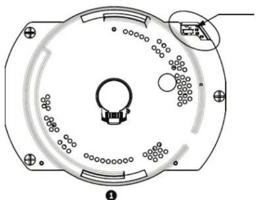
NOTICE! If control is not established, ensure that the RS-232/RS-485 selector switch is positioned to RS-485 (outward toward the LED lights). This switch is located on the bottom of the AutoDome CPU board, under the camera head and next to the LED lights. See Figure 4.1.
natural_image
Technical diagram of a circular mechanical component with internal holes and a close-up inset showing a connector (no text or symbols)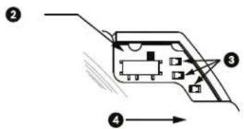
text_image
Diagram of an electronic component with labeled parts and directional arrows indicating flow or movement.Figure 4.1 RS-232/RS-485 Selection Switch
| 1 | C | P | U | M | o | d | u | I | e |
| 2 | Switch | Location | |||||||
| 3 | L | E | D | s | |||||
| 4 | RS | 485 | |||||||
4.2.2 Pelco Keyboard Commands
Pelco control commands are composed of a sequence of two (2) keyboard inputs with the following convention: 1) a Command Number and 2) a Function key input. The AutoDome uses the PRESET command key to save and recall presets (pre-positions) 1 through 99.

NOTICE! To save a preset, enter the desired number and hold the PRESET key for approximately two (2) seconds. To recall a preset, enter the desired preset number (or command) and momentarily press and release the PRESET key.
4.2.3 Pelco Keyboard Commands
| Keyboard Command User Action Description | ||
| 0-Pattern | Press | Initiates recording continuous playback based upon current Recording setting (A or B) in the Setup Menu. |
| Press and hold | Initiates recording based upon current Recording setting (A or B) in the Setup Menu. Press ACK to end recording. | |
| 1-Pattern Press Initiate | Recording A continuous playback. | |
| Press and hold | Initiate Recording A. Press ACK to end recording. | |
| 2-Pattern Press Initiate | Recording B continuous playback. | |
| Press and hold | Initiate Recording B. Press ACK to end recording. | |
| 3-Pattern | Press | Initiate the AutoDome standard preset tour (Tour 1). |
| 4-Pattern | Press | Initiate the AutoDome custom preset tour (Tour 2). |
| 1 - Aux On / Aux Off | Press Activates / deactivates alarm output 1. | |
| 2 - Aux On / Aux Off | Press Activates / deactivates alarm output 2. | |
| 3 - Aux On / Aux Off | Press Activates / deactivates alarm output 3. | |
| 4 - Aux On / Aux Off | Press Activates / deactivates alarm relay. | |
| 91 - Aux On Press Activate Zone Scan (display zone titles). | ||
| 92 - Aux On Press Activate Zone Scan (re-move zone titles) | ||
4.2.4 Special Preset Commands
Some Pelco mode preset commands have a special meaning and override the normal Pelco preset function as follows:
| Preset Command Description | |
| 33-PRESET | Pans the AutoDome 180° (Flip). |
| 34-PRESET | Goes to Zero Pan (original home position). |
| 80-PRESET | Toggles the Synchronization Mode between Line Lock and Internal (Pelco Frame Scan). This command is available if commands are unlocked using the Main menu. |
| 81-PRESET | Initiates Preset Tour 1. |
| 82-PRESET | Initiates Preset Tour 2. |
| 92-PRESET | Sets the Left pan limit for an AutoScan with Limit Stops enabled. |
| 93-PRESET | Sets the Right pan limit for an AutoScan with Limit Stops enabled. |
| 94-PRESET | Initiates a Preset Tour. |
| 95-PRESET | Enables or disables Limit Stops in the Setup Menu for AutoScan. Invokes the Pelco main Setup Menu when pressed for 2 seconds. |
| 96-PRESET | Stops a scan. |
| 97-PRESET | Initiates FastAddress (Pelco Random Scan). |
| 98-PRESET | Toggles the Synch. Mode between Line Lock and Internal (Pelco Frame Scan). This command is available only for two (2) minutes after the power is applied and then reverts to normal preset functionality. |
| 99-PRESET | Starts an AutoScan |

NOTICE! Some Pelco controllers do not support all the preset command numbers. Consult the specific Pelco controller's documentation for supported preset commands.
5 Pelco On-Screen Menus
You can program the AutoDome through the Pelco on-screen display (OSD) menus. To access the Pelco menus, you must configure the AutoDome for Pelco Mode and invoke the Pelco main Setup Menu.
5.1 Setup Menu
The Pelco main Setup Menu provides access to the programmable AutoDome settings. Some menu items are locked and require a system password to use. Menu items marked with an * are the default settings.
To open the Pelco main Setup Menu (locked commands):
- Press 95-PRESET (press the PRESET button for approximately 2 seconds to open).
- Use the joystick to highlight a menu item.
- Press either the Focus or the Iris key to open a menu item.
- Follow the on-screen instructions at the bottom of the screen.
| Setup Menu |
| Exit...Command Lock: OFFBosch MenuCamera SetupPTZ SetupEdit Password*FastAddress: Not SetAdvancedSoftware VersionAck and Reset AlarmsRestore All SettingsReset All Memory*= Factory SettingFocus / Iris: Select |

NOTICE! Use Zoom to select the Exit item from anywhere in a menu.
| Menu Description | |
| Exit Exits the menu. | |
| Command Lock (locked) | Allows or prohibits accessing locked commands. (If password is set, you are prompted to enter the password. |
| Bosch Menu (locked) | Accesses the full AutoDome configuration menu and all AutoDome settings. |
| Camera Setup Accesses | the White Balance and Night Mode camera settings. |
| PTZ Setup | Accesses the tours, tour periods, scan speed, edit presets, limit stops, recording, and AutoPivot settings. |
| Edit Password (locked) | Changes the password. |
| FastAddress (locked) | Sets or changes a camera address. |
| Software Version Displays the current software versions. | |
| Ack and Reset Alarms | Acknowledges and resets active alarms. |
| Restore All Settings (locked) | Restores all settings to their original default setting. |
| Reset All Memory (locked) | Clears all settings, including scene shots, tours, and recordings stored in the AutoDome memory. |

NOTICE! After a period of 4.5 minutes of inactivity, the OSD menu times-out and exits without warning. Some unsaved settings can be lost!
5.1.1 Command Lock (locked)
The Pelco Command Lock Menu allows or prohibits the use of locked commands. The default setting is ON.

NOTICE! If the Command Lock is set to ON and you press Focus or Iris on a locked command, the AutoDome displays the on-screen message: "Command is Locked."
5.1.2 Bosch Menu (locked)
The Bosch Menu allows full access to the AutoDome main Setup Menu and all AutoDome configuration settings.
| Pelco menu Bosch menu | ||
| Setup Menu Setup Menu | ||
| Exit...Command Lock: OFF Exit...Bosch MenuCamera SetupPTZ SetupEdit Password*FastAddress: Not SetAdvancedSoftware VersionAck and Reset AlarmsRestore All SettingsReset All Memory*= Factory SettingFocus / Iris: Select | Camera SetupLens SetupPTZ SetupDisplay SetupCommunication SetupAlarm SetupLanguageAdvancedDiagnosticsFocus / Iris: Select | |
Refer to Section 2: On-Screen Display Menu Navigation for a complete description of Bosch menus and configuration settings.
Camera Setup (unlocked)
The Pelco Camera Setup Menu provides access to camera settings.
| Camera Setup |
| Exit...* White Bal: OUTDOOR* Night Mode: AUT |
| * = Factory SettingFocus / Iris: Select |
Camera Setup Menu Choices:
| Menu Description | Sub-menu / Description | Default | Setting |
| Exit Exits the menu. | |||
| White Balance | Sets a default value in case the Pelco controller disables the white balance. | OUTDOOR: Sets a default setting if the controller disables white balance.INDOOR: Sets a default setting if the controller disables white balance. | OUTDOOR |
| Night Mode | Switches from color to monochrome. | ON: Sets Night Mode on.OFF: Sets Night Mode off.AUTO: Sets Night Mode to Auto set. | ON (Day/Night models only) |
5.1.3 PTZ Setup (unlocked)
The Pelco PTZ Setup Menu provides access to the PTZ settings such as tours, scan speed, presets, limit stops, recording, and AutoPivot.
| PTZ Setup | |
| Exit... | |
| * Edit Tour 1... | |
| * Edit Tour 2... | |
| * Tour 1 Period: | 5 sec |
| * Tour 2 Period: | 5 sec |
| * Scan Speed | 30 deg/sec |
| Edit Presets... | |
| * Limit Stops: | OFF |
| * Recording: | "A" |
| * Autopivot: | ON |
| * = Factory Setting | |
| Focus / Iris: Select | |
PTZ Setup Menu Choices:
| Menu Description | Sub-menu / Description Default | Setting | |
| Exit Exits the menu. | |||
| Edit Tour 1(300 and 500i Series) | Accesses the Add / Remove Scenes On Standard Tour 1 Menu. | Exit: Exits the menu.Scene (1 - 5): Adds or removes scenes from the Standard Tour. | |
| Edit Tour 2(300 and 500i Series) | Accesses the Edit Custom Tour Menu. | Exit: Exits the menu.Scene (1 - 5): Adds or removes scenes from the Custom Tour. | |
| Tour 1 Period Changes the length of waiting time between presets. | Sliding scale: - (3 sec. to 10 min.) + | 5 sec. | |
| Tour 2 Period Changes the length of waiting time between presets. | Sliding scale: - (3 sec. to 10 min.) + | 5 sec. | |
| Scan Speed Changes the Autopan and AutoScan speeds. | Sliding scale: - (1°/sec to 60°/sec) + | 30°/sec. | |
| Edit Presets Modifies preset scenes. 1-99 scenes | |||
| Limit Stops Toggles the Limit Stops for AutoScan. | ON or OFF | OFF | |
| Recordings(300 and 500i Series) | Selects record Pattern 1 or 2, if normal pattern command does not respond. | “A” or “B” | “A” |
| AutoPivot | Follows a subject while beneath the camera, without inverting the picture. | ON or OFF | ON |
5.1.4 Other Menus
| Menu | Description | Default Setting |
| Edit Password (locked, 300 and 500i Series) | Sets or displays the password. See Section 1.4 Setting Passwords, page 10. | |
| FastAddress (locked) | Sets or changes the AutoDome address. | Not Set |
| Software Version (unlocked) | Displays the camera software version. | |
| Ack and Reset Alarms (unlocked, 300 and 500i series) | Acknowledges and resets alarms. If there is no active alarm input, the OSD displays the following message: “No Active Alarms.” | |
| Restore All Settings (locked) | Restores all settings to their original factory default settings. | |
| Reset All Memory (locked) | Restores all settings to their original factory default settings and clears all user programmed settings such as preset scenes and recordings. |
6 Keyboard Commands by Number
| Locked Function Key | Comm No. | Command Description Series | 200 | Series 300 | Series 500i | |
| On/Off 1 | Scan 36 | 0° Autopan without limits * ** | ||||
| On/Off 2 | Autopan | Autopan between limits *** | ||||
| * | On/Off 3 | Iris Control | Enters menu (auto, manual) *** | |||
| * | On/Off | 4 | Focus Control | Enters menu (spot, auto, manual) | * | * |
| On/Off 7 | Play Custom Pre-position Tour | Activate/Deactivate | ** | |||
| On/Off 8 | Play Pre-position Tour | Activate/Deactivate *** | ||||
| * | On/Off 9 | Inactivity Mode | Enters menu (Off, Return to Scene 1, Recall Previous PTZ Command) | * | * | * |
| * | On/Off | 11 | Auto Iris Level adjust | Enters Iris Level Adjustment menu | * | * |
| On/Off 14 | Set Autopan and Scan Speed | Enters speed adjustment slide bar | * | * | ||
| On/Off 15 | Set Pre-position Tour Period (dwell) | Enters dwell adjustment slide bar | * | * | ||
| * | On/Off | 18 | AutoPivot Enable | Enables/disables AutoPivot | * | * |
| On/Off | 20 | Backlight Comp | Backlight Compensation | * | * | |
| * | On/Off | 23 | Electronic Shutter | Enters Shutter Speed slide bar | * | * |
| On/Off | 24 | Stabilization | Electronic Stabilization | |||
| On/Off 26 | Wide Dynamic Range (WDR camera only) | Activate/Deactivate | ** | |||
| * | On/Off | 35 | White Balance Mode | Enters White Balance menu | * | * |
| * | On | 40 | Restore Camera Settings | Restores all setting to their original defaults | * | * |
| * | On/Off | 41 | Line Lock Phase Adjust | Enters delay adjustment slide bar | * | * |
| * | On/Off 42 | Sync Mode | On-Line Lock Off-Internal | * | * | |
| * | On/Off | 43 | Auto Gain Control | AGC-On, Auto, Off | * | * |
| * | On/Off | 44 | Sharpness | Enters Sharpness menu | * | * |
| * | On | 46 | Advanced menu | Enters Main Setup menu | * | * |
| On | 47 | View Factory Settings | View all menu default settings | * | * | |
| On/Off | 50 | Playback A, continuous | Activate/Deactivate | * | ||
| On/Off 51 | Playback A, single Activate/D | * * | ||||
| On/Off | 52 | Playback B, continuous | Activate/Deactivate | * | ||
| On/Off | 53 | Playback B, single | Activate/Deactivate | * | ||
| On/Off | 56 | Night Mode menu | On, Off, Auto (Day/Night only) | * | * | |
| On/Off 57 | Night Mode setting | Enables/disables Night Mode (Day/Night only) | * | * | ||
| Locked | Function Key | Comm No. | Command | Description | Series 200 | Series 300 | Series 500i |
| * On/Off | 58 Day/ | Night Th | reshold On-menu (Day/Night only) *** | ||||
| On/Off 59 | Night | Mode Priority Motion-Activates Night Mode before slow shutter, preserving full-frame integration as light is reduced.Color-Activates slow shutter before Night Mode, preserving color longer as light is reduced. | |||||
| * On/Off | 60 On | Screen Di | display On-enable | Off-disable | * | * | * |
| * On 61 | Display Adjust | Adjust On-screen | Display *** | ||||
| On 62 Pre-position | Title menu Enters Pre-position Title menu.Refer to Section 3.3 Specifying a Shot or a Sector Title, page 30. | * | * | * | |||
| * On 63 | Zone Title menu | Enters Zone Title menu. Refer to Section 3.3 Specifying a Shot or a Sector Title, page 30. | * | * | * | ||
| On 64 Alarm Status | Enters Alarm Status menu | * * | |||||
| Off | 65 Alarm Acknowledge Acknowledge alarm or deactivate physical outputs | * | * | ||||
| On 66 Display software version Displays software version number | * | * | * | ||||
| * On/Off | 69 Alarm rule activation/deactivation | On-Enables all alarm rulesOff-Disables all alarm rules | * | * | |||
| On 72 Re-initialize camera Performs camera/lens re-initialization functions | * | * | * | ||||
| On/Off 78 AutoTrack Turns AutoTrack on or off | * | ||||||
| * On 79 | Camera Height | Enters the Camera Height menu | * | ||||
| * On/Off | 80 Digital Zoom | Lock Turns digital zoom on and off ** | |||||
| On/Off 81 Alarm | Output 1Open Collector | On-activates outputOff-deactivates output | * | * | |||
| On/Off 82 Alarm | Output 2Open Collector | On-activates outputOff-deactivates output | * | * | |||
| On/Off 83 Alarm | Output 3]Open Collector | On-activates outputOff-deactivates output | * | * | |||
| On/Off 84 Alarm | Output 4Relay | On-activates outputOff-deactivates output | * | * | |||
| * | On/Off | 86 | Sector Blanking | Enters Sector Blanking menu | * | * | |
| * On/Off | 87 Privacy Masking | Enters Privacy Masking menu ** | |||||
| On/Off 90 Comm | and Lock/Unlock On-lock onOff-lock off | * | * | * | |||
| * On/Off | 91 Lens | Polarity | menu On-reverse | Off-normal | * | * | * |
| * On/Off | 92 Lens | Polarity | menu On-reverse | Off-normal | * | * | * |
| * On/Off | 93 Lens | Polarity | menu On-reverse | Off-normal | * | * | * |
| On/Off 10 | 00 Record A Activate/Deactivate * * | ||||||
| On/Off 10 | 01 Record B Activate/Deactivate * * | ||||||
| On | 997 | FastAddress, display | Display current address | * | * | * | |
| On 998 F | fastAddress, all units Display and program current address | * | * | * | |||
| On 999 F | fastAddress, unaddressed domes | Display and program unaddressed AutoDomes | * | * | * | ||
| Set | “1-99” | Pre-position programming | Set ##-programs a preset view | “1-64” | ** | ||
| Shot | “1-99” | Pre-position recall | Shot ##-recall programmed preset | “1-64” | ** | ||
| Set | 100 | Pre-position menu | Enters the Pre-position menu | * | * | * | |
| Set/Shot | 101 Autopan left limit Set | set-programs left limit Shot-shows limit | * | * | * | ||
| Set/Shot | 102 Autopan right limit Set | set-programs right limit Shot-shows limit | * | * | * | ||
| Set | 110 Factory P/T home position | Set-recalibrate home position | * | ** | |||
| * | Set | 802 | Edit Password | Enters the Edit Password menu | * | * | |
| * Set | 899 Reset ALL | Restores all settings to original defaults and clears all user-programmed settings | * | * | * | ||
| Set | 900 Edit Tour 1 (Standard) Enters | the Standard Tour Scene menu | * | * | |||
| Shot | 900 | Edit Tour 2 (Custom) | Enters the Custom Tour Scene menu | * | * | ||
| Set/Shot | 901-999 | Adds/Removes a preposition shot from Tour 1 | Set ###-adds preset Shot ###-removes preset | 901-964 | ** | ||
7 Advanced Features
This chapter details the advanced features of the AutoDome Modular Camera System.
7.1 Alarm Rules (300 and 500i Series Only)
The 300 and 500i Series AutoDomes feature a powerful alarm rule engine. In its simplest form, an alarm rule defines those inputs that activate specific outputs. In its more complex form, a rule can be programmed to take any combination of inputs and keyboard commands to perform a dome function. There are numerous combinations of alarm inputs and outputs that can be programmed into twelve alarm rules.
7.1.1 Controlling Alarm Rules
The AUX 69 command allows a user to enable or disable all alarm rules. By default, alarm rules are enabled until the OFF-69-ENTER command is issued from a keyboard (there is no corresponding menu item for this command). Disabling alarms rules does not erase the rule, the AutoDome preserves the user-defined settings and the rule data is restored when the ON-69-ENTER command is issued.
The OFF-69-ENTER command performs the following actions:
- Disables all alarm rules
- Displays the message "Ack and Reset Alarms" if an alarm-rule triggered alarm is active when the AutoDome receives the disable command. You must acknowledge the alarm before the rule is disabled.
- Prevents the modification of an alarm rule while disabled.
7.1.2 Alarm Rule Examples
Following are three examples for setting up alarm rules. The first example is a basic alarm rule, and the second and third examples are more complex.
Example 1: Basic Alarm Rule
Scenario: We want a door alarm contact to:
- Flash an OSD message (***ALARM 1***) on the display when the alarm is triggered.
- Move the AutoDome camera to a saved position. (For this example Shot 7.)
- Transmit a Bilinx signal over the coax cable to the headend system, such as an Allegiant, to trigger an alarm response.
The sequence to program the above alarm rule example is as follows:
- Wire the door contact to Input 1 in the AutoDome. This circuit is normally open.
- Define the Alarm Input(s)
- From the Inputs Setup menu, ensure that Alarm Input 1 is set to N.O. (This is the default setting for Input 1.)

NOTICE! For instruction on wiring alarm and relay connections, see the AutoDome Modular Camera System Installation Manual.
- Define the Alarm Outputs from the Outputs Setup menu:
a. Ensure Output 5 is set to OSD. (This is the default setting for Output 5.)
b. Set Output 6 to Shot 7.
c. Set Output 7 to Transmit (a Bilinx signal to the head end).
- Set up the Alarm Rule (for this example use Rule 1). Select the Inputs from the Rule Setup menu:
a. Select Rule 1.
b. Set the first input to Alarm Input 1.
- Select the outputs:
a. Set the first output to OSD.
b. Set the second output to Shot 7.
c. Set the third output to Transmit.
- Enable the rule:
– Highlight Enabled and select YES.
Example 2: Advanced Alarm Rule
Scenario: A 500i Series AutoDome located at an airport is set to AutoPan Between Limits from the parking garage to the airport terminal. The gate entering the airport has an alarm contact connected to the AutoDome, and the perimeter fence in the area of the gate has an infrared (IR) motion detection sensor connected to the AutoDome.
When both the gate contact and motion detector alarms are activated at the same time, we want the alarm rule to:
- Flash an OSD message (***ALARM 2***) on the monitor.
- Stop the AutoPan and move the camera to a saved position (Shot 5) viewing the fence.
- Turn on AutoTrack.
- Transmit a Bilinx signal to the head end system to trigger an alarm response.
The sequence to program this alarm rule example is as follows:
- Wire and set the alarm Input(s).
a. Wire the motion detector to Input 1. (This circuit is normally open.)
b. Wire the gate alarm contact to Input 5. (This circuit is normally closed.)

NOTICE! For instruction on wiring alarm and relay connections, see the AutoDome Modular Camera System Installation Manual.
- From the Inputs Setup menu:
a. Ensure Input 1 (the motion detector) is set to N.O. (This setting is the default for Input 1.)
b. Ensure Input 5 (the gate contact) is set to N.C.
- Set the alarm Outputs from the Outputs Setup menu:
a. Set Output 5 to OSD.
b. Set Output 6 to Transmit.
c. Set Output 7 to Shot 5.
d. Set Output 8 to AutoTrack.
- Set up the Alarm Rule (for this example use Rule 2). Select the alarm Inputs:
a. From the Rule Setup menu select Rule 2.
b. Set the first input to Alarm Input 1. (The motion detector.)
c. Set the second input to Alarm Input 5. (The gate alarm contact.)
- Select the alarm Outputs:
a. Set the first output to OSD.
b. Set the second output to Shot 5 viewing the fence.
c. Set the third output to AutoTrack and select Latched.
d. Set the fourth output to Transmit (a Bilinx signal to the headend).
- Enable the alarm Rule:
- Highlight Enabled and select YES.
Example 3: Advanced Alarm Rule using AutoTrack
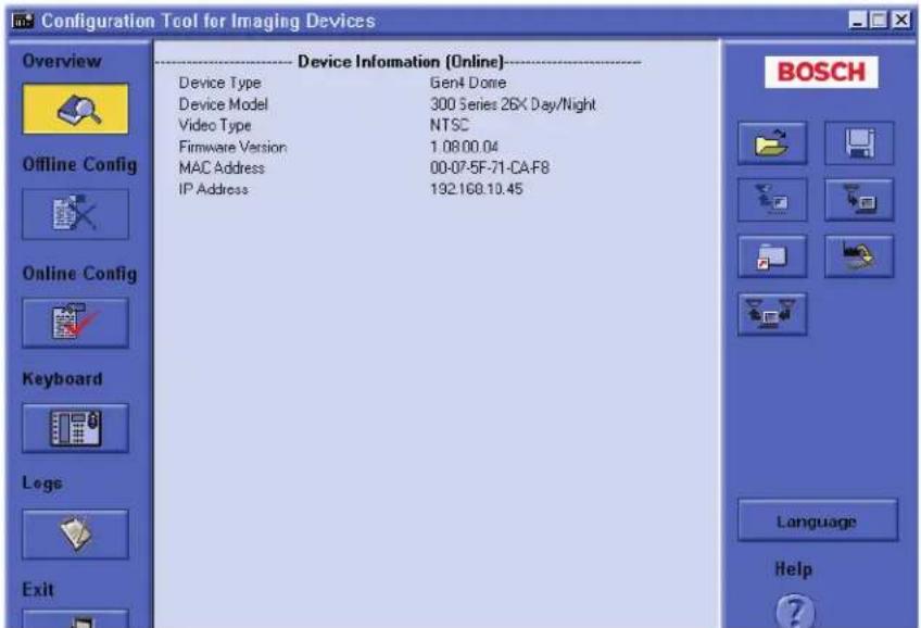
The following example explains how to set an alarm rule that moves the camera to a preset position and then activates the AutoTrack feature to track an intruder after an alarm is triggered. This example uses the Configuration Tool for Imaging Devices (CTFID) software tool. Refer to the Configuration Tool for Imaging Devices User Guide, available at www.boschsecurity.com.
- Launch the CTFID software from a computer that is connected to a VG4 AutoDome.
text_image
Configuration Tool for Imaging Devices Overview Device Information (Online)---- Device Type Gen4 Dome Device Model 300 Series 26X Day/Night Video Type NTSC Firmware Version 1.08.00.04 MAC Address 00-07-5F-71-CA-F8 IP Address 192.168.10.45 BOSCH Offline Config Online Config Keyboard Legs Exit Language HelpFigure 7.1 CTFID Overview Window
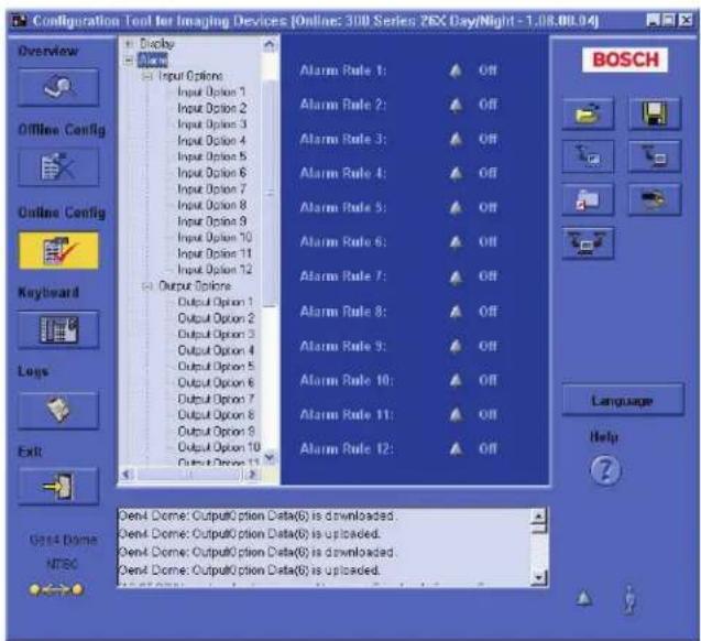
- Click the Online Config button and then expand Alarm.
text_image
Configuration Tool for Imaging Devices [Online: 300 Series 26X Day/Night -1.08.00.04] Overview Offline Config Online Config Keyboard Logs Exit Display Input Options Input Option 1 Input Option 2 Input Option 3 Input Option 4 Input Option 5 Input Option 6 Input Option 7 Input Option 8 Input Option 9 Input Option 10 Input Option 11 Input Option 12 Output Options Output Option 1 Output Option 2 Output Option 3 Output Option 4 Output Option 5 Output Option 6 Output Option 7 Output Option 8 Output Option 9 Output Option 10 Output Option 11 Output Option 12 Alarm Rule 1: Off Alarm Rule 2: Off Alarm Rule 3: Off Alarm Rule 4: Off Alarm Rule 5: Off Alarm Rule 6: Off Alarm Rule 7: Off Alarm Rule 8: Off Alarm Rule 9: Off Alarm Rule 10: Off Alarm Rule 11: Off Alarm Rule 12: Off Oen4 Dome: Output0 cition Data(6) is downloaded. Oen4 Dome: Output0 cition Data(6) is uploaded. Oen4 Dome: Output0 cition Data(6) is downloaded. Oen4 Dome: Output0 cition Data(6) is uploaded.Figure 7.2 Expanded Alarm Group
-
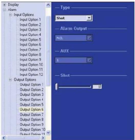
Expand Output Options; then click Output Option 5.
-
Select Tracking from the Type drop-down list.
-
Click Output Option 6.
-
Select Shot from the Type drop-down list.
-
Type the number 1 or use the slide bar to specify shot number 1. (Shot numbers must be set prior to configuring an alarm rule. See Section 3.2 Setting Preset Shots, page 30, for instructions).
The AutoDome moves to this preposition when the alarm rule is true.
text_image
Display Alarm Input Options Input Option 1 Input Option 2 Input Option 3 Input Option 4 Input Option 5 Input Option 6 Input Option 7 Input Option 8 Input Option 9 Input Option 10 Input Option 11 Input Option 12 Output Options Output Option 1 Output Option 2 Output Option 3 Output Option 4 Output Option 5 Output Option 6 Output Option 7 Output Option 8 Output Option 9 Output Option 10 Output Option 11 Type Shot Alarm Output NO. AUX 1 Shot 1Figure 7.3 Output Option 6 Configuration
-
Expand Alarm Rule; then click Alarm Rule 1.
-
Click the Yes radio button to enable the rule.
-
Type the number 1 or use the slider bar to select 1 for the Input option.
-
Select Alarm Input 1 from the Input Option drop-down list.
-
Ensure that the Output number is set to 1.
-
Select Shot 1 from the Output Options drop-down list.
This option instructs the AutoDome to move to pre-position shot 1 when Input 1 is true.
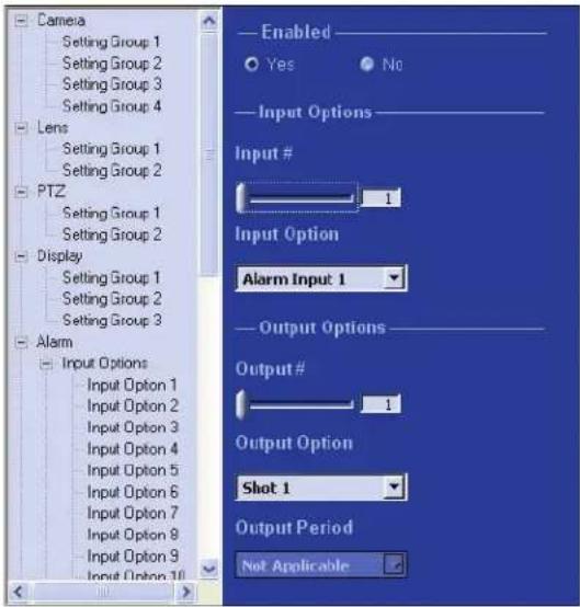
text_image
Camera Setting Group 1 Setting Group 2 Setting Group 3 Setting Group 4 Lens Setting Group 1 Setting Group 2 PTZ Setting Group 1 Setting Group 2 Display Setting Group 1 Setting Group 2 Setting Group 3 Alarm Input Options Input Option 1 Input Option 2 Input Option 3 Input Option 4 Input Option 5 Input Option 6 Input Option 7 Input Option 8 Input Option 9 Input Option 10 Enabled Yes No Input Options Input # 1 Input Option Alarm Input 1 Output Options Output # 1 Output Option Shot 1 Output Period Not ApplicableFigure 7.4 Alarm Rule 1 Configuration
- Move the Output slider bar to Output 2.
- Select Tracking from the Output Option drop-down list.
This option instructs the AutoDome to activate the AutoTrack feature after the input alarm is triggered and after the AutoDome moves to pre-position 1.
- Select 5 sec from the Output Period drop-down list.
This option instructs the AutoDome to turn off the AutoTrack feature after five seconds from when the tracked object is out of view.
7.2 AutoTrack Operation (500i Series Only)
The 500i Series AutoDome features enhanced AutoTrack software with more versatility and smoother object tracking. AutoTrack is now able to continuously follow an individual even if the person passes behind a Privacy Mask. When used with Virtual Mask, it is able to ignore predefined areas of background motion.
You can manually start AutoTrack or program the VG4 500i Series AutoDome to automatically turn on AutoTrack.
- Manual
- Enter the keyboard command ON-78-ENTER.
- In Pelco Mode, open the Main menu, select the Advanced menu, and then select AutoTrack On.
- Automatic
– During a pre-position tour.
- D u r i n g A u t o P a n .
- AutoDome activates AutoTrack after a period of Inactivity (Return to Scene 1 or Return to Previous Aux), if AutoTrack is programmed for these activities.

NOTICE! For proper operation AutoTrack requires that the camera height be set in the software. Open the Bosch Main menu, select the Advanced menu and select Camera Height to enter the height.
7.2.1 AutoTrack Settings and Recommendations
AutoTrack operates by recognizing an individual in motion and zooms-in to approximately 50% of the field of view for an average target height of six feet. In addition to the camera height, other factors may interfere with AutoTrack operation.
Setting the Camera Height
To ensure smooth tracking set the Camera Height accurately. Bosch recommends a minimum camera height of 3.6 m (12 ft).
- Press OFF-90-ENTER to turn off the command lock.
- Press ON-46-ENTER to access the Main Menu.
- Use the joystick to highlight the Advanced menu.
- Press Focus/Iris to open the menu.
- Enter a value between 3.6 m (12 ft) and 100 m (328.1 ft).
- Press Focus/Iris again to accept the camera height value.
-
Exit the Advanced menu; then exit the Main menu.
-
Highlight the Camera Height option and press the Focus/Iris button.
Ensuring Smooth AutoTrack Operation
Factors such as the viewing angle and unwanted motion (from trees, for example) may interfere with AutoTrack operation. Use the following recommendations to ensure smooth AutoTrack operation:
- Mount/Mounting Surface Stability
- Mount the camera in the most stable position. Avoid locations affected by vibrations, such as those caused by a roof-top air conditioner. These vibrations may cause complications when the camera zooms-in on a target.
- Use the pendant arm mount, if possible. This mount option provides the most stability for the camera.
- Use guy wires to protect against strong winds if using the parapet mount.
- Field of View
- Select a location and viewing angle that allows the flow of people to move across the camera's field of view.
- Avoid motion that moves directly towards the camera.
- Avoid locations that attract large numbers of people, such as retail stores or intersections.
- Unwanted Motion
- Use the Virtual Masking feature (see Section 7.3 Virtual Masking (500i Series Only), page 52) to mask unwanted motion from trees or cars. Bosch recommends that you draw the virtual mask 10% larger than the object to be masked.
- Avoid neon lights, flashing lights, night time lights, and reflected light (from a window or mirror, for example). The flickering of these lights can affect the AutoTrack operation. Use a Virtual Mask to hide these type of lights if they cannot be avoided.
- Check the virtual mask periodically to ensure that it still covers the entire object to be masked. Adjust the mask if necessary.
7.2.2 AutoTrack Optimization
The AutoDome achieves optimum tracking performance when the focal length of the lens during AutoPan is as close to the focal length of the lens during an AutoTrack operation. The ambient light conditions also affect the AutoTrack performance.
Dynamic Light Conditions
The ambient lighting conditions affect AutoTrack performance, especially in outdoor dynamic lighting conditions that change daily or hourly. To optimize the AutoTrack performance under changing light conditions, Bosch recommends that you configure the AutoTrack Sensitivity and the AutoPan speeds.

NOTICE! The VG4 AutoDome Service Pack 1.05 contains upgrades that allow the AutoDome to activate the AutoTrack while in AutoPan mode.
Bosch recommends setting the AutoTrack Sensitivity to Auto and suggests the following AutoPan speed for outdoor conditions:
| Camera Focal Length M | Maximum Suggested AutoPan Speed (degrees/sec) |
| Near-field (Wide Angle) 5 | |
| Mid-field 2 | |
| Far-field (Telephoto) 1 |
If you need a higher AutoPan speed, set the AutoTrack Sensitivity to a value between 1 and 10 in the Advanced Feature Setup menu.
Setting AutoTrack Optimization Parameters
-
Turn off the command lock (if active):
-
From a keyboard: press OFF-90-ENTER.
-
From the Aux Control tab (located on the LIVEPAGE view): enter 90-OFF.
-
Access the Main Menu:
-
From a keyboard: press ON-46-ENTER.
-
From the Aux Control tab: enter 46-ON.
-
Access the Advanced Feature Setup menu.
-
Select the AutoTrack Sensitivity option and change the parameter to Auto or to a value between 1-10.
- Exit the AutoTrack Sensitivity menu. Then, exit the Advanced Feature Setup menu.
- Access the PTZ Setup menu.
- Select the AutoPan option and change the parameter to one of the suggested values in the table above.
- Exit the AutoPan menu. Then, exit the PTZ Setup menu and finally exit the Main menu.
Consistent Light Conditions
You may use higher AutoPan speeds in consistent indoor or outdoor ambient light conditions, but Bosch recommends not exceeding a speed of more than 15 degrees/sec. Then modify the AutoTrack Sensitivity setting to reach the optimal results.
7.3 Virtual Masking (500i Series Only)
Virtual Masking is a unique Bosch technology that allows you to create an “invisible” area that ignores unwanted background motion. These invisible masks are similar to privacy zones, except that the AutoDome AutoTrack and Motion Detection algorithms can see them.
- To configure a Virtual Mask, open the Main menu, select the Advanced menu, then select Virtual Masking. To setup a Virtual Mask follow the on-screen menu instructions.
- In Pelco Mode, open the Main menu, select the Advanced menu, then select Virtual Masking. To setup a Virtual Mask follow the on-screen menu instructions.

NOTICE! Draw the mask 10% larger than the object to ensure that the mask completely covers the object as the AutoDome zooms in and out.
7.4 Privacy Masking (300 and 500i Series Only)
Privacy Masking is used to block out a specific area of a scene from being viewed. Mask choices have been expanded to include black, white, or blurred, and can be configured with three, four, or five corners to cover more complex shapes.

NOTICE! Privacy Masking does not hinder AutoTrack from tracking an object.

- To configure a Privacy Mask, open the Main menu, select Display Setup, and then select Privacy Mask. Alternatively, enter the keyboard command ON-87-ENTER. To setup a privacy mask, follow the on-screen menu instructions.
- In Pelco Mode open the Pelco Main menu, open the Bosch menu, select the Display Setup menu, and finally select Privacy Masking. To setup a privacy mask, follow the on-screen menu instructions.
NOTICE! Draw the mask 10% larger than the object to ensure that the mask completely covers the object as the AutoDome zooms in and out.
7.5 Motion Detection with Region of Interest (500i Series Only) (Preset positions 90 through 99)
With the 500i Series AutoDome, the motion detection software can be configured to create a Region of Interest within multiple preset positions or scenes. It can take advantage of Virtual Masking to ignore motion in predefined areas. Motion Detection can also be used as an Alarm Rule input.
Preset positions 90 through 99 are reserved for programming motion detection scenes.

NOTICE! Motion Detection always takes precedence over AutoTrack object tracking.
To set up a scene with Motion Detection:
- Choose an unused Preset position from 90 to 99. For this example use Preset scene 95.
- Enter the keyboard command SET-95-ENTER.
- Select YES at the Apply Motion Detection? prompt. (If NO is selected, the Preset scene does not activate Motion Detection.)
- Select YES at the Apply Region of Interest? prompt. (If NO is selected, the entire scene is used for Motion Detection.)
- Follow the on-screen menu instructions to construct the shape of the screen area you want to detect motion within.

NOTICE! Up to five (5) anchor points can be used to form the area which you want to detect motion within. Motion Detection is not activated until the Preset scene is recalled. The Motion Detection icon "M" appears in the upper left-hand corner of the display.
7.6 Image Stabilization (500i Series Only)
Image Stabilization becomes increasingly important as zoom ranges are extended. The advanced image stabilization algorithms of the 500i Series eliminate camera shake for exceptional image clarity. Bosch achieves this clarity without reducing camera sensitivity or picture quality.
- To configure image stabilization, open the Main menu, select the Advanced menu, and then select Stabilization to turn on the feature.
- In Pelco Mode open the Main menu, select the Advanced menu, and then select Stabilization to turn on the feature.
7.7 Pre-position Tour
The 200 Series AutoDome features one (1) standard preset tour, while the 300 and 500i Series AutoDomes feature two (2) preset tours. Each preset scene is saved for playback later. Tour 1 is a standard tour that only recalls the scenes in the exact sequence they were shot. Scenes can be added or deleted on the tour, but the sequence cannot be changed. To add or remove scenes on Tour 1 enter the keyboard command SHOT-900-ENTER and follow the on-screen instructions.
Tour 2 (300 and 500i Series only) is a customizable tour that allows you to rearrange the sequence of scenes on the tour by inserting and deleting scenes. To enter the Edit Tour 2 menu, enter the keyboard command SET-900-ENTER and follow the on-screen instructions.
8 Using the IP AutoDome
The VG4-200, VG4-300, and VG4-500i Series AutoDomes can be ordered with an optional IP module that allows the AutoDome to transmit PTZ control commands and images over a TCP/IP network. It also allows users to configure the AutoDome camera display settings, camera operating settings, and to configure the network parameters.
The IP AutoDome incorporates a network video server in the IP module. The primary function of the server is to encode video and control data for transmission over a TCP/IP network. With its MPEG-4 encoding, it is ideally suited for IP communication and for remote access to digital video recorders and multiplexers. The use of existing networks means that integration with CCTV systems or local networks can be achieved quickly and easily. Video images from a single camera can be simultaneously received on several receivers.
8.1 Overview of Features
The IP module adds the following functionality to an AutoDome system:
| Function Description | |
| Video Encoding | The camera uses the H.264 compression standard and ensures that the data rate remains low even with high image quality and can also be adapted to local conditions within wide limits. |
| Dual Streaming | Encodes dual data streams simultaneously according to two individually customized profiles. This feature creates two (2) data streams per camera that can serve different purposes. For example, one (1) data stream for local recording and one (1) data stream optimized for transmission over the Local Area Network (LAN). |
| Multicast | Enables simultaneous, real-time transmission to multiple receivers. The network must implement the UDP and IGMP V2 protocols as a prerequisite for Multicasting. |
| Configuration | Allows configuration for all camera settings from a Web browser on the local network (Intranet) or on the Internet. You can also update the firmware, load device configurations, store configuration settings, and copy these settings from one camera to another. |
| Snapshots | Allows you to take and store individual video frames as JPEG images from the Web browser interface. |
| Backup Saves video | Images as a file on a computer's hard drive from the Web browser interface. |
| Audio | Switches between Biphase-in to Audio-in (line 2V P-P) microphone. |
| Record | Allows configuration for the recording options of the IP module. You can record video from the Livepage to a hard drive or you can opt to store up to 8 MB of video on the IP module. |
8.2 System Requirements
The AutoDome Easy II IP requires specific software and hardware to allow a user to view live images and to configure camera settings over a TCP/IP network. These requirements are:
- A computer with the Microsoft Windows XP or Vista operating system, network access, and the Microsoft Internet Explorer Web browser version 7.0 or later, or
- A computer with the Microsoft Windows XP or Vista operating system, network access, and reception software such as the Bosch VIDOS software or the Bosch Divar XF, or
- A compatible hardware decoder from Bosch Security Systems as a receiver and a connected video monitor.
If you choose to use a computer running Microsoft Internet Explorer or any of the Bosch software, the computer must conform to the following minimum requirements:
- Processor: 1.8 GHz Pentium IV
- RAM: 256 MB
- Video system: 128 MB video memory, 1024x768 display with a minimum of 16-bit color
- Network interface: 100-BaseT
- Microsoft Internet Explorer, version 7.0 or higher
- You must install the following software (available on the Bosch Security Systems, Inc. Web site at www.boschsecurity.com)
- D i r e c t X 9 . 0 c
- Java Virtual Machine
- MPEG ActiveX utility
- . N e t 2 . 0
- VideoSDK

NOTICE!
Ensure the graphics card is set to 16-bit or 32-bit color. If you need further assistance, contact your PC system administrator.
8.3 Connecting the IP AutoDome to the PC
- Install the IP AutoDome according to the instructions in the AutoDome Modular Camera System Installation Manual.
- Connect an Ethernet cable from the IP AutoDome RJ45 connector to a dedicated network switch to bypass the Local Area Network (LAN).
- Connect the dedicated network switch to the RJ45 connector on the PC (see option A below).

NOTICE!
The IP AutoDome can also be connected directly to a PC using an Ethernet crossover cable with RJ45 connectors (see option B below).
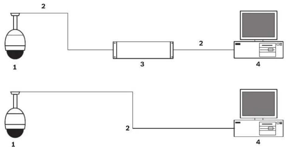
Figure 8.1 IP AutoDome System Configuration
| 1 | A | u | t | o | D | o | m | e |
| 2 | I | P | C | o | n | n | e | c |
| 3 Network Switch | ||||||||
| 4 | C | o | m | p | u | t | e | r |
t i o n
8.4 Configuring the IP AutoDome Camera
To operate the camera in your network you must assign it a valid network IP address. The default IP address is 192.168.0.1, but you may have to change this address if it conflicts with another device on your network.
To properly configure the camera for your network, you need the following information:
- Unit IP address: An identifier for the camera on a TCP/IP network. For example, 140.10.2.110 is a valid syntax for an IP address.
- Subnet mask: A mask used to determine what subnet an IP address belongs to.
- Gateway IP address: A node on a network that serves as an entrance to another network.
- Port: An endpoint to a logical connection in TCP/IP and UDP networks. The port number identifies the use of the port for use through a firewall connection.

NOTICE!
Ensure that the network parameters of your cameras are available before you begin configuration.
The IP AutoDome defaults are as follows:
- IP Address: 192.168.0.1
- Subnet Mask: 255.255.255.0
- Gateway IP Address: 0.0.0.0
The following sections provide instructions about installing the software necessary to view images over an IP connection, configuring the IP network settings and accessing the IP AutoDome images from a Web browser.
8.5 Installing the Required Software
To view live video, you must install Bosch MPEG ActiveX, DirectX, and Java Virtual Machine. To view live video from an IP-enabled VG4 AutoDome in Microsoft Internet Explorer or to change VG4 AutoDome configurations, you must install the following software in this order:
- Sun Java
- Microsoft .NET
- Microsoft DirectX
- MPEG-ActiveX
- Bosch Configuration Manager
You can find the latest versions of the required software on the Bosch Security Systems, Inc. Web site. To locate the software, follow these directions:
-
Launch a Web browser and navigate to one of the following URLs:
-
For customers in the United States: http://www.boschsecurity.us
-
For customers outside of the United States: http://www.boschsecurity.com, then click your region and finally click the link for your country (if available).
-
Click the CCTV or Products link (depending on the country Web site) in the left pane of the Web page.
-
Click the Software link under the Download Library section in the left pane.
- Click OK to agree to the Bosch Software License Agreement.
- Click the CCTV link under the Software heading in the center frame.
- Click the Cameras, PTZ link to access the software for Bosch PTZ cameras.
After you click Cameras, PTZ the browser opens the Software Download page for VG4 and VEZ AutoDomes.
- Scroll down the page to the AutoDome TCP/IP Communications Module heading.
-
Right-click the appropriate language selection and choose Save Target As from the pop-up menu for these software packages:
-
Sun Java
- Microsoft .NET
- Microsoft DirectX
- M P E G - A c t i v e X
-
ConfigManager
-
Save each software package to the computer that contains the Microsoft Internet Explorer you will use to view the live video images from an IP-enabled VG4 AutoDome.
You should now have the following software packages stored on the computer:
- MPEG-ActiveXXX_enUS_E3366678923.zip (MPEG-ActiveX)
- DirectXXXX_enUS_E2352554507.zip (DirectX)
-dotnetfx_enUS_T5007298827.exe (.NET) - jre-XXXX-windows-i586-p-s_xxXX_XXXXXXXX.Xe (Java)
- SetupConfigManagerXXXXXXXX_enUS_F4155139595.exe (ConfigManager)
Note: The XXX denotes the software version number. This number changes as updates are made to the software packages.
-
Install the software packages using the procedure below:
-
Unzip the MPEG-ActiveXXX_enUS_E3366678923.zip and the DirectXXXX_enUS_E2352554507.zip files. Ensure that you maintain the directory structures for each software package.
- Double-click the jre-XXXX-windows-i586-p-s_xxXX_XXXXXXXXX.exe file to initiate the Java installation.
- Follow the Java Installation Wizard instructions until the software is installed.
- Double-click dotnetfx_enUS_T5007298827.exe to initiate the .NET installation.
- Follow the .NET Installation Wizard instructions until the software is installed.
- Open the DirectXXXX directory. Then, double-click the dxsetup.exe file to initiate the DirectX installation.
- Follow the DirectX Installation Wizard instructions until the software is installed.
- Double-click MPEGAx.exe to initiate the MPEG-ActiveX installation.
– Follow the MPEG-ActiveX Installation Wizard instructions until the software in installed. - Double-click SetupConfigManagerXXXXXXXX_enUS_F4155139595.exe to initiate the ConfigManager installation.
-
Follow the ConfigManager Installation Wizard instructions until the software is installed.
-
Launch Microsoft Internet Explorer and navigate to the URL of an IP-enabled VG4 AutoDome. Ensure that you can see the live video in the Livepage.
-
Launch the Configuration Manager utility and verify that the IP-enabled VG4 AutoDomes in your security system are listed. (You may have to configure some settings in the Configuration Manager.)
8.5.1 Changing the Network Settings
The IP Module has a default IP address of 192.168.0.1. To change the IP address or any network settings, you can use the Configuration Manager software supplied on the CD or the IP AutoDome Web Server.

NOTICE!
Contact your local network administrator for a valid IP address, Subnet Mask, and a Gateway IP Address.
Using the Configuration Manager
Configuration Manager is an optional network utility provided on the Bosch Security Systems Web site (see Section 8.5 Installing the Required Software, page 57). Use the Configuration Manager Manual provided in the Documentation folder on the CD to make any configuration changes.

NOTICE!
Depending on the PC network security settings, the user may have to add the new IP address to the browser's trusted sites list for the IP AutoDome controls to operate.
Using the IP AutoDome Web Server
The IP AutoDome incorporates a network video server in the IP module.
To configure the camera using the IP AutoDome Web server, do the following:
- Set the IP address on the PC to 192.168.0.10 to ensure that the PC and the IP AutoDome are on the same Subnet.
- Launch Microsoft Internet Explorer and navigate to the following URL: http://192.168.0.1 The Web browser opens the LivePage for the IP AutoDome; a security warning message is displayed.
- Check the Always Trust box, then click YES.
- Click the Settings link, located at the top of the LivePage.
- Click the Service Settings link, located in the left pane of the Settings window.
- Click the Network link to open the Network Settings page.
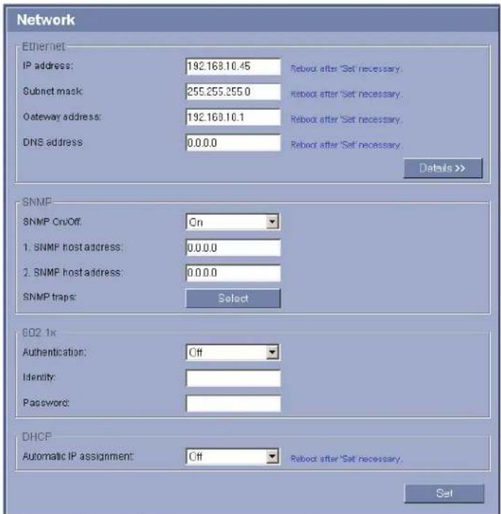
text_image
Network Ethernet IP address: 192.168.10.45 Reboot after 'Set' necessary. Subnet mask: 255.255.255.0 Reboot after 'Set' necessary. Gateway address: 192.168.10.1 Reboot after 'Set' necessary. DNS address 0.0.0.0 Reboot after 'Set' necessary. Details >> SNMP SNMP On/Off: On 1. SNMP host address: 0.0.0.0 2. SNMP host address: 0.0.0.0 SNMP traps: Select 002 1x Authentication: Off Identity: Password: DHCP Automatic IP assignment: Off Reboot after 'Set' necessary. SetFigure 8.2 Network Settings Page
- Configure the settings on this page based on the addresses provided by your local network administrator.

NOTICE!
Click the Help on this page? link if you need more information.
- Click the Set button to save the settings.
- Launch another instance of Microsoft Internet Explorer.
- Type the original IP address followed by /reset (for example, http://192.168.0.1/reset) in the address bar and click Go to restart the IP AutoDome. Once you restart the IP AutoDome, use the new IP Address to access the LivePage.
- Disconnect the IP AutoDome Ethernet cable from the dedicated network switch and reconnect the Ethernet cable to the local area network (LAN).
8.6 The LIVEPAGE
Once the connection is established, the Web browser displays the LIVEPAGE. It shows the live video image on the right of the browser window. Depending on the configuration, various text overlays may be visible on the live video image (see the IP AutoDome online help).
Other information may be shown next to live video image on the LIVEPAGE. The display depends on the settings on the Livepage Configuration page (see the IP AutoDome online help).
Maximum Number of Connections
If you do not connect, the unit may have reached its maximum number of connections. Depending on the unit and network configuration, each IP AutoDome can have up to 25 Web browser connections or up to 50 connections via VIDOS or Bosch Video Management System.
Protected IP AutoDome
If the IP AutoDome is password protected against unauthorized access, the Web browser displays a corresponding message and prompts you to enter the password when you attempt to access protected areas.

NOTICE!
An IP AutoDome offers the option to limit the extent of access using various authorization levels (see the IP AutoDome online help).
- Enter the user name and associated password in the corresponding text fields.
- Click OK. If the password is entered correctly, the Web browser displays the page that was called up.
Protected Network
If a RADIUS server is employed in the network for managing access rights (802.1x authentication), the IP AutoDome must be configured accordingly, otherwise no communication is possible.
Image Selection
You can view the image of the camera in different displays.
▶ Click one of the tabs Stream 1, Stream 2 or M-JPEG below the video image to toggle between the different displays of the camera image.
View Control
The View Control tab allows you to control camera functions (pan, tilt, zoom, focus, and iris), navigate through on-screen menus and to view preset shots.
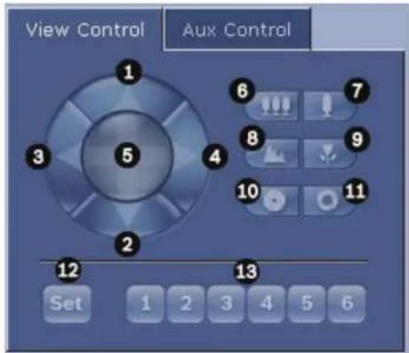
text_image
View Control Aux Control 1 2 3 4 5 6 7 8 9 10 11 12 13 Set 1 2 3 4 5 6| Number | Description Number Description | ||
| 1 Tilts the camera up 8 | Focus far ^2 | ||
| 2 Tilts the camera down 9 | Focus near ^2 | ||
| 3 Pans the camera to the left 10 | Iris close ^2 | ||
| 4 Pans the camera to the right 11 | Iris open ^2 | ||
| 5 | Pans and tilts the camera in all directions | 12 | Sets the position for corresponding pre-sets 1, 2, 3, 4, 5, and 6 |
| 6 | Zoom out ^1 | 13 | Moves the camera to pre-set shot numbers 1, 2, 3, 4, 5, and 6 |
| 7 | Zoom in ^1 | ||
| 1. This function is also accessible by using the mouse scroll wheel while in the Live video frame. | |||
| 2. This button is also used as the “Enter” button to select menu items from the AUX tab. | |||
- To control a peripheral, click the appropriate controls.
- Move the mouse cursor over the video image. Additional options for controlling peripherals are displayed with the mouse cursor.
- To manually pan throughout the image area, move your cursor over any part of the live video. The image area displays a directional arrow (Ikjmhigf), then click and hold the right mouse key to pan the camera.
Digital I/O
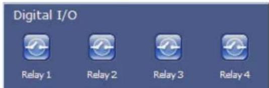
text_image
Digital I/O Relay 1 Relay 2 Relay 3 Relay 4The alarm icons Input 1 to Input 4 are for information purposes and indicate the status of an alarm input: When an alarm is triggered, the corresponding icon lights up blue. The unit's configuration determines whether the alarm is displayed, as well as additional details (see the IP AutoDome online help).
Triggering Relay
You can switch connected units using the relays in the IP AutoDome (for example lights or door openers).
To activate this, click the icon for the corresponding relay next to the video image. The icon will be red when the relay is activated.
System Log / Event Log
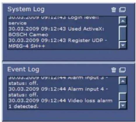
text_image
System Log 30.03.2009 09:12:43 Login level: service 30.03.2009 09:12:43 Used ActiveX: BOSCH Cameo 30.03.2009 09:12:43 Register UDP - MPEG-4 SH++ Event Log 30.03.2009 09:12:44 Alarm input 3 - status: off. 30.03.2009 09:12:44 Alarm input 4 - status: off. 30.03.2009 09:12:44 Video loss alarm 1 detected.The System Log field contains information about the operating status of the IP AutoDome and the connection. You can save these messages automatically in a file (see the IP AutoDome online help).
Events such as the triggering or end of alarms are shown in the Event Log field. You can save these messages automatically in a file.
- If you want to delete the entries, click the delete icon in the top right-hand corner of the relevant field.
- If you want to view a detailed log, click the icon in the top right-hand corner of the relevant field. A new window will open.
Audio Function
Depending on the configuration, the IP AutoDome can send and receive audio signals. All users who are connected by browsers receive the audio signals sent by the IP AutoDome.
Audio signals can only be sent to the IP AutoDome by the user who connects to the unit first.
- On the LIVEPAGE, click anywhere next to the video image to remove the focus from the ActiveX.
- Hold down the F12 key to make a voice connection to the IP AutoDome. The browser's status bar displays the message Send Audio ON.
- Release the F12 key when you want to stop sending audio signals to the IP AutoDome. The status bar in Internet Explorer displays the message Send Audio OFF.

NOTICE!
When the connection maintaining voice contact with the IP AutoDome is broken, the next user to make a connection to the IP AutoDome can send audio data to the IP AutoDome.
8.6.1 Entering a Keyboard Control Command
The Aux Control tab is used to enter keyboard control commands. These commands are composed of a command number plus the appropriate function key (Show Shot, Set Shot Aux On or Aux Off). A valid combination either issues a command to the camera or displays an on-screen menu.
Aux Control Tab
The Aux Control tab is used to enter pre-programmed keyboard control commands. See Section 6 Keyboard Commands by Number, page 43, for a list of all commands. To access the Aux Control tab, navigate to the Livepage and click the Aux Control tab (see Figure 8.3 below).

NOTICE!
The Aux Control tab can also be used to display the OSD menus. Once the OSD menus are displayed, the virtual joystick in the View Control tab can be used to navigate the menus, and the Focus and Iris buttons can be used to make menu selections.
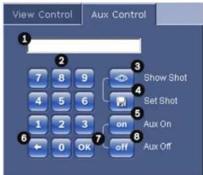
text_image
View Control Aux Control 1 2 3 Show Shot 4 Set Shot 5 on 6 Aux On 7 0 OK off Aux OffFigure 8.3 Aux Control Tab
| Number Description | |
| 1 Command number field | |
| 2 Keypad (numbers 0-9) | |
| 3 Show a preset shot | |
| 4 Set a preset shot | |
| 5 Initiates a command | |
| 6 Deletes a number in the Command Number field | |
| 7 Used to select a menu item | |
| 8 Stops a command |
To Enter a Keyboard Control Command:
- Place the cursor in the Command Number field.
- Click the desired command number via the on-screen keypad.
- Click either the Aux On or the Aux Off button to initiate or stop the command. See Section 6 Keyboard Commands by Number, page 43, for a list of commands.
- If the command initiates a menu, use the Up/Down arrows on the View Control to navigate the menu. Click the Focus or Iris button to select a menu item.
To Set a Preset Shot:
Preset shots (or scenes) are camera positions that are saved in memory for future use.
- Move your cursor over the live image and wait for the area to display a directional arrow.
- Click and hold a mouse button to pan to the desired position you want to save.
- Click any number combination from 1-99 (1-64 for a 200 Series AutoDome, 90-99 for 500i Series AutoDome are used for motion detection) from the on-screen keypad to identify the scene number.
- Click the Set Shot button. The image area displays a message that indicates which shot number was saved.
To View a Preset Shot:
- Click the number of the scene you want to view using the on-screen keypad.
- Click the Show Shot button.

NOTICE!
For more information about the IP AutoDome settings and controls, click the Help on this page? link to open the IP AutoDome online help.
8.7 Saving Snapshots
You can save individual images from the video sequence currently shown on the LIVEPAGE in JPEG format on your computer's hard drive. The icon for recording single images is only visible if the unit is configured to enable this process.
▶ Click the icon. The image is saved at a resolution of 704 × 576 pixels (4CIF). The storage location depends on the configuration of the IP AutoDome.

8.8 Recording Video Sequences
You can save sections of the video sequence currently shown on the LIVEPAGE on your computer's hard drive. The icon for recording video sequences is only visible if the unit is configured to enable this process.
- Click the icon to start recording. The storage location depends on the configuration of the IP AutoDome. A red dot in the icon indicates that recording is in progress.

- Click the icon again to stop recording.

NOTICE!
You can play back saved video sequences using the Player from Bosch Security Systems, which can be installed from the product CD supplied.
Image Resolution
Sequences are saved at the resolution that has been preset in the configuration for the encoder (see the IP AutoDome online help).
8.9 Running Recording Program
The hard drive icon below the camera images on the LIVEPAGE changes during an automatic recording.

A moving graphic will appear to indicate a running recording. If no recording is taking place, a static icon is displayed.
9 VG4 Audio Connections
The audio version of the VG4 AutoDome has one audio input for line signals. The audio signals are transmitted one-way and in-sync with the video signals. As a result, a door intercom system can be connected at the camera location.

NOTICE! The line ports of the intercom should be used for transmitting audio signals on the intercom systems.
9.1 Audio Line Input Specifications
The following Line In specifications should be complied with in all cases:
- 5.5 Vpp max. Input voltage Impedance 9 Kohm, typicalSampling rate 8 KHz, 16 Bit, mono

NOTICE! There is an internal gain level adjustment in case the signal level is too low.
9.1.1 Wire Specifications
Long distances are more susceptible to introducing noise into the signal.
Wire Type: Coax wire, AWG is dependant on the connector style selected Maximum Distance: Depends on the signal level
9.1.2 Connections
The Audio Input must be connected to the Biphase Input as follows:
- Remove the 110 ohm Biphasic termination resistor.
- Connect an audio source with line level to the Biphase input of the VG4 as shown in the chart below:
| Contact Description | |
| Biphase + Audio In | |
| Biphase - Ground |
9.1.3 Activating Audio Reception
To configure audio via the Web browser, do the following:
- Open the IP AutoDome LivePage, then click the Settings tab.
- Click the Camera Settings link from the left pane, then click Miscellaneous. The IP AutoDome displays the Audio settings.
- Click the Audio radio button to activate audio over IP.

NOTICE! The audio signal is sent in a separate data stream parallel to the video data, and so increases the network load. The audio data is encoded according to G.711 and requires an additional bandwidth of approximately 80 Kbit/s for each connection.
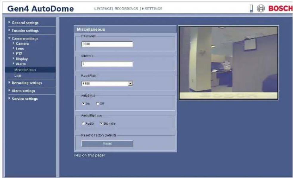
text_image
Gen4 AutoDome LIVEPAGE | RECORDINGS | SETTINGS General settings Encoder settings Camera settings Camera Lens PTZ Display Alarm Miscellaneous Logs Recording settings Alarm settings Service settings Miscellaneous Password 0000 Address: 7 Baud Rate 4800 AutoBaud On Off Audio/Biphasal Audio Biphasal Reset to Factory Defaults Reset Help on this page? BOSCHFigure 9.1 Configuring Audio Settings
9.1.4 Enabling Audio Transmission
To transmit audio via the IP connection, do the following:
- Open the IP AutoDome LivePage, then click the Settings tab.
- Click Service Settings from the left pane, then click Livepage Configuration. The IP AutoDome displays the Livepage Configuration screen (see Figure 9.2).
- Click the Transmit Audio radio button to enable for audio.
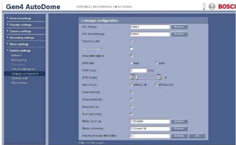
text_image
Gen4 AutoDome LIVEPAGE | RECORDINGS | SETTINGS General settings Encoder settings Camera settings Recording settings Alarm settings Service settings Network Multicoding Encryption Version information Livepage configuration System state Maintenance Livepage configuration URL for logs: Default URL for device logs: Default Transmit audio: Show signal output: Show relay outputs: JPEG Slot: large small JPEG Delay: 0 (ms) JPEG Quality: High Low 4 Video format: MPEG4 J BP: MPEG4 J AVO: Show event log: Show system log: Save event log: Save system log: File for event log: C EventId File for system log: C General Id Fish for JPEG and MPEG files: CL Help on this page? BOSCIFigure 9.2 Livepage Configuration
9.1.5 Configuring Gain (optional)
Input gain control is supported over a range of -34B to +12dB. The current video image is shown in the small window next to the slide controls to help verify the audio source and improve the Peak levels. Set the gain of the audio signals to suit your specific requirements. Changes are effective immediately. The current level is displayed next to the slide control to help do this. Make sure that the display does not go beyond the green zone during modulation.
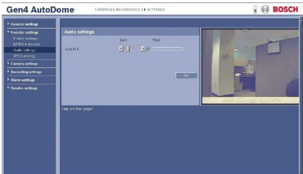
text_image
Gen4 AutoDome LIVEPAGE1 RECORDINGS 1 > SETTINGS General settings Encoder settings Picture settings MPEG-4 encoder Audio settings JPEG encoding Camera settings Recording settings Alarm settings Service settings Audio settings Gait Peak Line to 1: 0 Set Help on this page? BOSCHFigure 9.3 Setting Audio
10 Configuring the IP AutoDome
The SETTINGS page provides access to the configuration menu, which contains all the unit's parameters arranged in groups. You can view the current settings by opening one of the configuration screens. You can change the settings by entering new values or by selecting a predefined value from a list field.
There are two options for configuring the unit or checking the current settings:
- Basic mode
- Advanced mode
In Basic Mode the most important parameters are arranged in seven groups. This allows you to change the basic settings with just a few entries and then put the device into operation.
Advanced Mode is recommended for expert users or system support personnel. You can access all unit parameters in this mode. Settings that affect the fundamental functionality of the unit (such as firmware updates) can only be altered in the advanced mode.
All parameter groups are described in this chapter in the order in which they are listed in the configuration menu, from the top of the screen to the bottom.

CAUTION!
The settings in the advanced mode should only be processed or modified by expert users or system support personnel.
All settings are backed up in the IP AutoDome memory so they are not lost even if the power fails.
Starting Configuration
▶ Click the SETTINGS link in the upper section of the window. The Web browser opens a new page with the configuration menu.
Navigation
- Click one of the menu items in the left window margin. The corresponding submenu is displayed.
- Click one of the entries in the submenu. The Web browser opens the corresponding page.
Making Changes
Each configuration screen shows the current settings. You can change the settings by entering new values or by selecting a predefined value from a list field.
▶ After each change, click Set to save the change.

CAUTION!
Save each change with the associated Set button.
Clicking the Set button saves the settings only in the current field. Changes in any other fields are ignored.
10.1 Basic Mode: Device Access
Device name
You can give the IP AutoDome a name to make it easier to identify. The name makes the task of administering multiple units in larger video monitoring systems easier, for example using the VIDOS or Bosch Video Management System programs.
The device name is used for the remote identification of a unit, in the event of an alarm for example. For this reason, enter a name that makes it as easy as possible to quickly identify the location.
 | CAUTION!Do not use any special characters, for example &, in the name.Special characters are not supported by the system's internal recording management and may therefore result in the Player or Archive Player programs being unable to play back the recording. |
| Camera 1The camera name makes it easier to identify the remote camera location, in the event of an alarm for example. It will be displayed in the video screen if configured to do so (see Section Camera name stamping, page 74). The camera name makes the task of administering cameras in larger video monitoring systems easier, for example using the VIDOS or Bosch Video Management System programs.Enter a unique, unambiguous name for the camera in this field. | |
 | CAUTION!Do not use any special characters, for example &, in the name.Special characters are not supported by the system's internal recording management and may therefore result in the Player or Archive Player programs being unable to play back the recording. |
| PasswordAn IP AutoDome is generally protected by a password to prevent unauthorized access to the unit. You can use different authorization levels to limit access.The IP AutoDome operates with three authorization levels: service, user and live.The highest authorization level is service. After entering the correct password, you can access all the functions of the IP AutoDome and change all configuration settings.With the user authorization level, you can operate the unit and also control cameras, for example, but you cannot change the configuration.The lowest authorization level is live. It can only be used to view the live video image and switch between the different live image displays.You can define and change a password for each authorization level if you are logged in as service or if the unit is not password protected.Enter the password for the appropriate authorization level here. | |
 | NOTICE!Proper password protection is only guaranteed when all higher authorization levels are also protected with a password. If a live password is assigned, for example, a service and a user password must also be set. When assigning passwords, you should therefore always start from the highest authorization level, service, and use different passwords. |
Confirm password
In each case, enter the new password a second time to eliminate typing mistakes.
10.2 Basic Mode: Date/Time
Device date/Device time/Device time zone
If there are multiple devices operating in your system or network, it is important to synchronize their internal clocks. For example, it is only possible to identify and correctly evaluate simultaneous recordings when all units are operating on the same time. If necessary, you can synchronize the unit with your computer's system settings.
Click the Sync to PC button to copy your computer's system time to the IP AutoDome.
Time server IP address
The IP AutoDome can receive the time signal from a time server using various time server protocols, and then use it to set the internal clock. The unit polls the time signal automatically once every minute.
▶ Enter the IP address of a time server here.
Time server type
Select the protocol that is supported by the selected time server. Preferably, you should select the SNTP server as the protocol. This supports a high level of accuracy and is required for special applications and subsequent function extensions.
Select Time server for a time server that works with the protocol RFC 868.
10.3 Basic Mode: Network
The settings on this page are used to integrate the IP AutoDome into an existing network. Some changes only take effect after the unit is rebooted. In this case, the Set button changes to Set and Reboot.
- Make the desired changes.
- Click the Set and Reboot button. The IP AutoDome is rebooted and the changed settings are activated.

CAUTION!
If you change the IP address, subnet mask or gateway address, the IP AutoDome is only available under the new addresses after the reboot.
DHCP
If a DHCP server is employed in the network for the dynamic assignment of IP addresses, you can activate acceptance of IP addresses automatically assigned to the IP AutoDome. Certain applications (VIDOS, Bosch Video Management System, Archive Player, Configuration Manager) use the IP address for the unique assignment of the unit. If you use these applications, the DHCP server must support the fixed assignment between IP address and MAC address, and must be appropriately set up so that, once an IP address is assigned, it is retained each time the system is rebooted.
IP address
Enter the desired IP address for the IP AutoDome in this field. The IP address must be valid for the network.
Subnet mask
Enter the appropriate subnet mask for the selected IP address here.
Gateway address
If you want the unit to establish a connection to a remote location in a different subnet, enter the IP address of the gateway here. Otherwise leave the box blank (0.0.0.0).
10.4 Basic Mode: Encoder Profile
Default profile
You can select a profile for encoding the video signal.
You can use this to adapt the video data transmission to the operating environment (for example network structure, bandwidth, data load).
Pre-programmed profiles are available, each giving priority to different perspectives. When selecting a profile, details are displayed in the list field. Below is a brief description of the factory default settings for the encoder profiles.

NOTICE!
The names and the technical details for the encoder profiles depend on the configuration of the device.
- High resolution 1
High quality, connections with the highest bandwidth, resolution 704 × 576/480 pixels
- High resolution 2
High quality, connections with high bandwidth, resolution 704 × 576/480 pixels
- Low bandwidth
High resolution, connections with low bandwidth, resolution 704 × 576/480 pixels
- DSL
DSL connections with 500 kbps, resolution 352 × 288/240 pixels
- ISDN (2B)
ISDN connections via two B-channels, resolution 352 × 288/240 pixels
- ISDN (1B)
ISDN connections via one B-channel, resolution 352 × 288/240 pixels
- MODEM
Analog modem connections with 20 kbps, resolution 352 × 288/240 pixels
- GSM
GSM connections with 9,600 baud, resolution 352 × 288/240 pixels
10.5 Basic Mode: Audio
You can set the gain of the audio signals to suit your specific requirements. Your changes are effective immediately.
If you connect via Web browser, you must activate the audio transmission on the LIVEPAGE
Functions page (see Section 10.13 Advanced Mode: LIVEPAGE Functions, page 76). For other connections, the transmission depends on the audio settings of the respective system.
Audio
The audio signals are sent in a separate data stream parallel to the video data, and so increase the network load. The audio data are encoded according to G.711 and require an additional bandwidth of approx. 80 kbps for each connection. If you do not want any audio data to be transmitted, select Off.
Line In
You can set the line input gain. Make sure that the display does not go beyond the green zone during modulation.
10.6 Basic Mode: Recording
For long-term, authoritative images, it is essential that you use an appropriately sized iSCSI system.
Here you can select a storage medium and immediately start or stop the recording.
Storage medium
- Select the required storage medium from the list.
- Click the Start button to start the recording immediately.
10.7 Basic Mode: System Overview
The data on this page are for information purposes only and cannot be changed. Keep a record of this information in case technical assistance is required.

NOTICE!
You can select all required text on this page with the mouse and copy it to the clipboard with the [Ctrl]+[C] key combination, for example if you want to send it via e-mail.
10.8 Advanced Mode: Identification
Device ID
Each IP AutoDome should be assigned a unique identifier that you can enter here as an additional means of identification.
Device name
You can give the IP AutoDome a name to make it easier to identify. The name makes the task of administering multiple units in larger video monitoring systems easier, for example using the VIDOS or Bosch Video Management System programs.
The device name is used for the remote identification of a unit, in the event of an alarm for example. For this reason, enter a name that makes it as easy as possible to quickly identify the location.

CAUTION!
Do not use any special characters, for example &, in the name.
Special characters are not supported by the system's internal recording management and may therefore result in the Player or Archive Player programs being unable to play back the recording.
Camera 1
The camera name makes it easier to identify the remote camera location, in the event of an alarm for example. It will be displayed in the video screen if configured to do so (see
Section Camera name stamping, page 74). The camera name makes the task of administering cameras in larger video monitoring systems easier, for example using the VIDOS or Bosch Video Management System programs.
Enter a unique, unambiguous name for the camera in this field. You can use both lines for this.

CAUTION!
Do not use any special characters, for example &, in the name.
Special characters are not supported by the system's internal recording management and may therefore result in the Player or Archive Player programs being unable to play back the recording.
You can use the second line for entering additional characters; these can be selected from a table.
- Click the icon next to the second line. A new window with the character map is opened.
- Click the required character. The character is inserted into the Result field.
- In the character map, click the << and >> icons to move between the different pages of the table, or select a page from the list field.
- Click the < icon to the right of the Result field to delete the last character, or click the X icon to delete all characters.
- Now click the OK button to apply the selected characters to the second line of the Camera 1 parameters. The window will close.
Initiator extension
You can attach your own text to the initiator name of the IP AutoDome to make the unit easier to identify in large iSCSI systems. This text is added to the initiator name, separated from it by a full stop. You can see the initiator name in the system overview (see Section 10.59 Advanced Mode: System Overview, page 116).
10.9 Advanced Mode: Password
An IP AutoDome is generally protected by a password to prevent unauthorized access to the unit. You can use different authorization levels to limit access.

NOTICE!
Proper password protection is only guaranteed when all higher authorization levels are also protected with a password. If a live password is assigned, for example, a service and a user password must also be set. When assigning passwords, you should therefore always start from the highest authorization level, service, and use different passwords.
Password
The IP AutoDome operates with three authorization levels: service, user and live.
The highest authorization level is service. After entering the correct password, you can access all the functions of the IP AutoDome and change all configuration settings.
With the user authorization level, you can operate the unit and also control cameras, for example, but you cannot change the configuration.
The lowest authorization level is live. It can only be used to view the live video image and switch between the different live image displays.
You can define and change a password for each authorization level if you are logged in as service or if the unit is not password protected.
Enter the password for the appropriate authorization level here.
Confirm password
In each case, enter the new password a second time to eliminate typing mistakes.
10.10 Advanced Mode: Date/Time
Date format
Select your required date format.
Device date/Device time
If there are multiple devices operating in your system or network, it is important to synchronize their internal clocks. For example, it is only possible to identify and correctly evaluate simultaneous recordings when all units are operating on the same time.
- Enter the current date. Since the unit time is controlled by the internal clock, there is no need to enter the day of the week – it is added automatically.
- Enter the current time or click the Sync to PC button to copy your computer's system time to the IP AutoDome.
Device time zone
Select the time zone in which your system is located.
Daylight saving time
The internal clock can switch automatically between normal and daylight saving time (DST). The unit already contains the data for DST switch-overs up to the year 2018. You can use these data or create alternative time saving data if required.

NOTICE!
If you do not create a table, there will be no automatic switching. When changing and clearing individual entries, remember that two entries are usually related to each other and dependent on one another (switching to summer time and back to normal time).
- First check whether the correct time zone is selected. If it is not correct, select the appropriate time zone for the system, and click the Set button.
- Click the Details button. A new window will open and you will see the empty table.
- Select the region or the city that is closest to the system's location from the list field below the table.
- Click the Generate button to generate data from the database in the unit and enter it into the table.
- Make changes by clicking an entry in the table. The entry is selected.
- Clicking the Delete button will remove the entry from the table.
- Select other values from the list fields below the table to change the entry. Changes are made immediately.
- If there are empty lines at the bottom of the table, for example after deletions, you can add new data by marking the row and selecting required values from the list fields.
- Now click the OK button to save and activate the table.
Time server IP address
The IP AutoDome can receive the time signal from a time server using various time server protocols, and then use it to set the internal clock. The unit polls the time signal automatically once every minute.
Enter the IP address of a time server here.
Time server type
Select the protocol that is supported by the selected time server. Preferably, you should select the SNTP server as the protocol. This supports a high level of accuracy and is required for special applications and subsequent function extensions.
Select Time server for a time server that works with the protocol RFC 868.
10.11 Advanced Mode: Display Stamping
Various overlays or “stamps” in the video image provide important supplementary information. These overlays can be enabled individually and are arranged on the image in a clear manner.
Camera name stamping
This field sets the position of the camera name overlay. It can be displayed at the Top, at the Bottom or at a position of your choice that you can then specify using the Custom option. Or it can be set to Off for no overlay information.
- Select the desired option from the list.
- If you select the Custom option, additional fields are displayed where you can specify the exact position (Position (XY)).
- In the Position (XY) fields, enter the values for the desired position.
Time stamping
This field sets the position of the time overlay. It can be displayed at the Top, at the Bottom or at a position of your choice that you can then specify using the Custom option. Or it can be set to Off for no overlay information.
- Select the desired option from the list.
- If you select the Custom option, additional fields are displayed where you can specify the exact position (Position (XY)).
- In the Position (XY) fields, enter the values for the desired position.
Display milliseconds
If necessary, you can also display milliseconds. This information can be useful for recorded video images; however, it does increase the processor's computing time. Select Off if you do not need to display milliseconds.
Alarm mode stamping
Select On to display a text message overlay in the image in the event of an alarm. It can be displayed at a position of your choice that you can then specify using the Custom option. Or it can be set to Off for no overlay information.
- Select the desired option from the list.
- If you select the Custom option, additional fields are displayed where you can specify the exact position (Position (XY)).
- In the Position (XY) fields, enter the values for the desired position.
Alarm message
Enter the message to be displayed in the image in the event of an alarm. The maximum text length is 31 characters.
Video watermarking
Choose On if you wish the transmitted video images to be “watermarked”. After activation, all images are marked with a green W. A red W indicates that the sequence (live or saved) has been manipulated.
10.12 Advanced Mode: Appearance
| On this page you can adapt the appearance of the web interface and change the website language to meet your requirements. If necessary, you can replace the manufacturer's logo (top right) and the product name (top left) in the top part of the window with individual graphics. | |
 | NOTICE!You can use either GIF or JPEG images. The file paths must correspond to the access mode (for example C:\Images\Logo.gif for access to local files, or http://www.mycompany.com/images/logo.gif for access via the Internet/Intranet).When accessing via the Internet/Intranet, ensure that a connection is always available to display the image. The image file is not stored in the IP AutoDome. |
| Website languageSelect the language for the user interface here.Company logoEnter the path to a suitable graphic if you want to replace the manufacturer's logo. The image file can be stored on a local computer, in the local network or at an Internet address.Device logoEnter the path to a suitable graphic if you want to replace the product name. The image file can be stored on a local computer, in the local network or at an Internet address. | |
 | NOTICE!If you want to use the original graphics again, simply delete the entries in the Company logo and Device logo fields. |
JPEG interval
You can specify the interval at which the individual images should be generated for the M-JPEG image on the LIVEPAGE.
10.13 Advanced Mode: LIVEPAGE Functions
On this page you can adapt the LIVEPAGE functions to your requirements. You can choose from a variety of different options for displaying information and controls.
- Check the box for the items that are to be made available on the LIVEPAGE. The selected items are indicated by a check mark.
- Check whether the required functions are available on the LIVEPAGE.
Transmit audio
The audio signals are sent in a separate data stream parallel to the video data, and so increase the network load. The audio data are encoded according to G.711 and require an additional bandwidth of approx. 80 kbps for each connection.
Lease time (s)
The lease time in seconds determines the time beyond which a different user is authorized to control the camera after no further control signals are received from the current user. After this time interval, the camera is automatically enabled.
Bilinx control
Next to the field for view control at the top left of the LIVEPAGE, an additional field is displayed for the special Bosch Security Systems Bilinx control.
Show alarm inputs
The alarm inputs are displayed next to the video image as icons along with their assigned names. If an alarm is active, the corresponding icon changes color.
Show relay outputs
Relay outputs are shown next to the video image as icons, along with their assigned names. If the relay is switched, the icon changes color.
Show VCA trajectories
The trajectories (motion lines of objects) from the video content analysis are displayed in the live video image if a corresponding analysis type is activated (see Section 10.48 Advanced Mode: VCA Event triggered, page 106).
Show VCA metadata
When the analysis function is activated, the additional information from the video content analysis (VCA) will be displayed in the live video image (see Section 10.48 Advanced Mode: VCA Event triggered, page 106). With the MOTION+ analysis type, for example, the sensor fields in which motion is recorded will be marked with rectangles.
Show event log
The event messages are displayed along with the date and time in a field next to the video image.
Show system log
The system messages are displayed along with the date and time in a field next to the video image and provide information about establishing and ending connections, for example.
Allow snapshots
Here you can specify whether the icon for saving individual images should be displayed below the live image. Individual images can only be saved if this icon is visible.
Allow local recording
Here you can specify whether the icon for saving video sequences on the local memory should be displayed below the live image. Video sequences can only be saved if this icon is visible.
Path for JPEG and Video files
- Enter the path for the storage location of individual images and video sequences that you can save from the LIVEPAGE.
- If necessary, click Browse to find a suitable directory.
10.14 Advanced Mode: Logging
Save event log
Check this option to save event messages in a text file on your local computer.
You can then view, edit and print this file with any text editor or the standard Office software.
File for event log
- Enter the path for saving the event log here.
- If necessary, click Browse to find a suitable directory.
Save system log
Check this option to save system messages in a text file on your local computer. You can then view, edit and print this file with any text editor or the standard Office software.
File for system log
- Enter the path for saving the system log here.
- If necessary, click Browse to find a suitable directory.
10.15 Advanced Mode: Picture Settings
You can set the video image of the camera to suit your requirements. The current video image is displayed in the small window next to the slide controls as confirmation. Your changes are effective immediately.
- Move the slide control to the required position.
- Click Default to reset all settings to their default value.
Contrast (0...255)
You can use this function to adapt the contrast of the video image to your working environment.
Saturation (0...255)
You can use this function to adjust the color saturation so as to make the reproduction of colors on your monitor as realistic as possible.
Brightness (0...255)
You can use this function to adapt the brightness of the video image to your working environment.
Low-pass filter (0...255)
You can use this function to filter very fine noise from the image. This reduces and optimizes the bandwidth necessary for image transmission over the network. The image resolution may be impaired.
The higher the value set with the slide control, the flatter the image signal. Check your setting in the image window next to the slide controls.
Also observe the processor load indicator that appears at the top of the window near the manufacturer's logo (see Section 8.5.1 Changing the Network Settings, page 58).
10.16 Advanced Mode: Encoder Profile
You can change the names and individual parameter values for the encoder profiles.
You can use this to adapt the video data transmission to the operating environment (for example network structure, bandwidth, data load).
Pre-programmed profiles are available, each giving priority to different perspectives. Below is a brief description of the factory default settings for the encoder profiles.
- High resolution 1
High quality, connections with the highest bandwidth, resolution 704 × 576/480 pixels
– High resolution 2
High quality, connections with high bandwidth, resolution 704 × 576/480 pixels - Low bandwidth
High resolution, connections with low bandwidth, resolution 704 × 576/480 pixels
- DSL
DSL connections with 500 kbps, resolution 352 × 288/240 pixels
- ISDN (2B)
ISDN connections via two B-channels, resolution 352 × 288/240 pixels
- ISDN (1B)
ISDN connections via one B-channel, resolution 352 × 288/240 pixels
- MODEM
Analog modem connections with 20 kbps, resolution 352 × 288/240 pixels
- GSM
GSM connections with 9,600 baud, resolution 352 × 288/240 pixels

CAUTION!
Change the profiles only once you are fully familiar with all the configuration options. In the default setting, Stream 1 is transmitted for alarm connections and automatic connections. Bear this fact in mind when assigning the profile.

NOTICE!
All parameters combine to make up a profile and are dependent on one another. If you enter a setting that is outside the permitted range for a particular parameter, the nearest permitted value will be substituted when the settings are saved.
Profile name
You can enter a new name for the profile. The name is then displayed in the Default profile list field on the Encoder Streams page in the lists of selectable profiles.
Target data rate
You can limit the data rate for the IP AutoDome to optimize utilization of the bandwidth in your network. The target data rate should be set according to the desired picture quality for typical scenes with no excessive motion.
For complex images or frequent changes of image content due to frequent movements, this limit can be temporarily exceeded up to the value you enter in the Maximum data rate field.
Maximum data rate
This maximum data rate is not exceeded under any circumstances. Depending on the video quality settings for the I and P-frames, this fact can result in individual images being skipped. The value entered here must be at least 10% higher than the value entered in the Target data rate field. If the value entered here is too low, it will automatically be adjusted.
Encoding interval
The setting selected here determines the interval at which images are encoded and transmitted. The image rate in ips (images per second) is displayed next to the text field.
Video resolution
Here you can select the desired resolution for the video image. The following resolutions are available:
- CIF
352 × 288/240 pixels
- 4CIF/D1
704 × 576/480 pixels
Expert Settings
You can use the expert settings to adapt the I-frame quality and the P-frame quality to specific requirements, if necessary. The setting is based on the H.264 quantization parameter (QP).
I-frame quality
This setting allows you to adjust the image quality of the I-frames. The basic setting Auto automatically adjusts the quality to the settings for the P-frame video quality. Alternatively, you can use the slide control to set a value between 9 and 51. The value 9 represents the best image quality with, if necessary, a lower frame refresh rate depending on the settings for the maximum data rate. A value of 51 results in a very high refresh rate and lower image quality.
P-frame quality
This setting allows you to adjust the maximum image quality of the P-frames. The basic setting Auto automatically adjusts to the optimum combination of movement and image definition (focus). Alternatively, you can use the slide control to set a value between 9 and 51. The value 9 represents the best image quality with, if necessary, a lower frame refresh rate depending on the settings for the maximum data rate. A value of 51 results in a very high refresh rate and lower image quality.
Default
Click Default to return the profile to the factory default values.
10.17 Advanced Mode: Encoder Streams
The IP AutoDome simultaneously generates two data streams (Dual Streaming); you can select the relevant property for these here and connect them to an encoder profile, for example one for transmissions to the Internet and one for LAN connections.
Two settings with different encoder properties are available:
- H.264 BP+ (HW decoder)
Select this setting when using hardware decoders or the Divar XF digital video recorder.
CABAC: off
CAVLC: on
GOP structure: IP
I-frame distance: 15
Deblocking filter: on
- H.264 MP Low Latency
Select this setting when using software decoders, PTZ and for rapid movements in the images.
CABAC: on
CAVLC: off
GOP structure: IP
I-frame distance: 30
Deblocking filter: on
- Select the required encoder properties and one of the encoder profiles for each data stream.
- Click the Preview button. The preview screens for both data streams are shown.
- Click the 1:1 Live View button below the preview screen to open a new window with the original data stream and to check the image quality and the transmission rate.
Property
Select the required encoder properties for the relevant data stream here.
Default profile
Select the required encoder profile here. The properties of the profiles are defined on the Encoder Profile page (see Section 10.16 Advanced Mode: Encoder Profile, page 78).
JPEG stream
You can set up the separate JPEG stream in this area. These settings are independent of the H.264 settings. The resolution corresponds to the highest setting from the two data streams.
Max. frame rate
You can select the frame rate for transmitting the JPEG images.
Picture quality
This setting allows you to define the picture quality. Low quality requires a lower bandwidth in the network.
10.18 Advanced Mode: Audio
You can set the gain of the audio signals to suit your specific requirements. The current video image is shown in the small window next to the slide controls to help you check the audio source and improve assignments. Your changes are effective immediately.
If you connect via Web browser, you must activate the audio transmission on the LIVEPAGE
Functions page (see Section 10.13 Advanced Mode: LIVEPAGE Functions, page 76). For other connections, the transmission depends on the audio settings of the respective system.
Audio
The audio signals are sent in a separate data stream parallel to the video data, and so increase the network load. The audio data are encoded according to G.711 and require an additional bandwidth of approx. 80 kbps for each connection. If you do not want any audio data to be transmitted, select Off.
Line In 1
You can set the line input gain. Make sure that the display does not go beyond the green zone during modulation.
10.19 Advanced Mode: Camera Options
10.20 Camera Settings Group 1
White Balance
Adjusts the color settings to maintain the quality of the white areas of the image.
- ATW: allows the camera to continuously adjust color reproduction.
- Indoor: white balance tracking for indoor use.
- Outdoor: white balance tracking for outdoor use.
- AWB Hold: places the ATW on hold and saves the color settings.
- Extended ATW (default): allows the camera to constantly adjust for optimal color reproduction.
Gain Control
Adjusts the automatic gain control (AGC). Automatically sets the gain to the lowest possible value needed to maintain a good picture.
- AGC (default): electronically brightens dark scenes, which may cause graininess in low light scenes.
- Fixed: no enhancement.
Max. Gain Level
Controls the maximum value the gain can have during AGC operation. To set the maximum gain level, type a value between 1 and 6 inclusive. The default setting is 4.
Sharpness
Adjusts the sharpness of the picture. To set the sharpness, type a value between 1 and 16 inclusive. The default setting is 12.
Sync. Mode
Selects the synchronization method for the camera.
- Line Lock: synchronizes the camera to AC power and eliminates picture roll in multi-camera systems.
- Internal (default): locks the power into the internal crystal.
Line Lock Delay
Adjusts the vertical line lock phase delay from 0^ to 359^ .
To set the Line Lock Delay, type a value, in degrees, between 0 (default) and 359 inclusive.
This setting optimizes the Line Lock mode to eliminate picture roll in multiphase power applications.
10.21 Camera Settings Group 2
Shutter Mode
- Off: turns the Auto SensUP Off.
- Auto SensUP (default): increases camera sensitivity by increasing the integration time on the CCD. This is accomplished by integrating the signal from a number of consecutive video frames to reduce signal noise.
Shutter
Adjusts the electronic shutter speed (AES). Controls the time period for which light is gathered by the collecting device. The default setting is 1/60 second.
Auto SensUp Maximum
Sets the Auto SensUp minimum value for the AutoDome. The Auto SensUp Min. value is the factor by which the sensitivity of the camera is increased. The default setting is 15x.
Night Mode (Day/Night models only)
Adjusts the filter operation of the camera.
- Off: activates day mode (color) and does not allow the camera to switch to the night mode.
- On: activates night mode to enhance lighting in low light scenes.
- Auto (default): allows the camera to set the Night Mode based on the light conditions of the scene.
Night Mode Threshold
Adjusts the level of light at which the camera automatically switches out of Night Mode (B/W) operation. 10 is earlier, 55 is later.
Night Mode Color
Switches an Auto IR filter in monochrome operation.
- On: color processing remains in effect while the camera is in night mode.
- Off (default): color processing is not in effect while the camera is in night mode.
10.22 Camera Settings Group 3
Backlight Compensation
Optimizes the video level for the selected area of the image. Parts outside this area may be underexposed or overexposed. Select On to optimize the video level for the central area of the image. The default setting is Off.
Stabilization
An algorithm that virtually eliminates camera shake in both the vertical and horizontal axes, resulting in exceptional image clarity. Select On to enable stabilization and Off to disable. The default setting is Off.
Wide Dynamic Range
Provides a sharper, more detailed image with outstanding accuracy in color reproduction. Select On to enable wide dynamic range and Off to disable. The default setting is Off.
10.23 Advanced Mode: Lens
10.24 Lens Settings Group 1
Auto Focus
Continuously adjusts the lens automatically to the correct focus for the sharpest picture.
- Spot (default): activates the Auto Focus feature after the camera stops moving. Once focused, Auto Focus is inactive until the camera is moved again.
- Constant: Auto Focus is always active.
- Manual: Auto Focus is inactive.
Auto Iris
Automatically adjusts the lens to allow the correct illumination of the camera sensor. This type of lens is recommended for use where there are low light or changing light conditions.
- Constant (default): camera constantly adjusts to varying light conditions (default).
- Manual: camera must be manually adjusted to compensate for varying light conditions.
Auto Iris Level
Increases or decreases brightness according to the amount of light. Type a value between 1 and 15, inclusive. The default setting is 8.
Iris Speed
Controls how fast the Iris will adjust the opening according to the illumination of the scene. Type a value between 1 and 10, inclusive. The default setting is 5.
Focus Speed
Controls how fast the Auto focus will readjust when the focus becomes blurred. Type a value between 1 and 8, inclusive. The default setting is 2.
Maximum Zoom Speed (200, 300, 500 models only)
Controls the zoom speed. The default setting is Fast.
10.25 Lens Settings Group 2
Digital Zoom
Digital zoom is a method of decreasing (narrowing) the apparent angle of view of a digital video image. It is accomplished electronically, without any adjustment of the camera's optics, and no optical resolution is gained in the process. Select Off to disable or On to enable this feature. The default setting is On.
Zoom Polarity
Capability to reverse the operation of the zoom button on the controller.
- Normal (default): zoom controls operate normally.
- Reverse: zoom controls are reversed.
Focus Polarity
- Normal (default): focus controls operate normally.
- Reverse: focus controls are reversed.
Iris Polarity
Capability to reverse the operation of the iris button on the controller.
- Normal (default): iris controls operate normally.
– Reverse: iris controls are reversed.
10.26 Advanced Mode: PTZ
10.27 PTZ Settings Group 1
Auto Pan Speed
Continuously pans the camera at a speed between right and left limit settings. Type a value between 1 and 60 (expressed in degrees), inclusive. The default setting is 30.
Standard Tour Period
Controls the waiting time until the dome moves to the next scene. Select a time period. The default is 5 seconds.
PTZ Fixed Speed
Controls the pan, tilt, zoom with a fixed speed value. Type a value between 1 and 15, inclusive. The default setting is 4.
Inactivity
Selects the time period the dome must be not controlled until the inactivity event will be executed.
- Off (default): camera remains on a current scene indefinitely.
- Scene 1: camera returns to Preset 1.
– Previous Aux: camera returns to the previous activity.
Inactivity Period
Determines the behavior of the dome when the control for dome is inactive. Select a time period from the pull-down list (3 sec. - 10 min.). The default setting is 2 minutes.
Auto Pivot
The Auto Pivot tilts the camera through the vertical position as the camera is rotated to maintain the correct orientation of the image. Set the Auto Pivot to On (default) to automatically rotate the camera 180° when following a subject traveling directly beneath the camera. To disable this feature, click Off.
10.28 PTZ Settings Group 2
Tracker
Automated motion tracking system. Select On (default) to enable the tracker or Off to disable this feature.
Camera Height
The camera height is a straight vertical height in respect to the surface that you are tracking. Use the slider bar to select the camera's height on a scale of 8-100. The default setting is 12.
Orientation
Reverses the image 180^ (ideal when mounting upside down). Set the orientation to Normal (default) or Inverted.
Freeze Frame
Select On (default) to freeze the image while the AutoDome moves to a predetermined scene position.
AutoTracker Sensitivity
Use the slider bar to select the sensitivity level on a scale of 0-20. The default setting is 0.
AutoTracker Timeout
When On, AutoTrack "gives up" after the Timeout Period if tracking in a confined area (for example a tree, a flag, etc). Select a timeout period; from 30 seconds to 1800 seconds (30 minutes).
10.29 Advanced Mode: Display
10.30 Display Settings Group 1
Title OSD
Controls how the camera displays the on-screen Sector and Scene titles.
- Off: no on-screen titles.
- On: always displays on-screen titles.
- Momentary (default: on-screen titles displayed for a few seconds, then hides the titles.
Camera OSD
Controls how the camera displays response information on the screen, such as Digital Zoom, Iris Open /Close and Focus Near/Far. Click the On (default) radio button to display the camera response information. Click Off to disable this feature.
Language
Select a language in which the OSD displays the titles and the response information. The default setting is English.
Display Position
To set the Display Position type a value between 1 and 16, inclusive, or use the slide control to set this value. The value zero (default) sets the position at the top-center of the on-screen display, while a value of 16 sets the position at the bottom-center of the on-screen display.
OSD Brightness
Adjusts the brightness for the OSD. The value 0 is the darkest display and 10 is the brightest display. To set the OSD Brightness, type a value between 0 and 10, inclusive, or use the slide control to set this value. The default setting is 7.
10.31 Display Settings Group 2
Scene
The AutoDome can store up to 99 preset scenes and this section allows you to apply a title for the scene and to indicate if the scene can be a part of a preset tour. Click Download to get the current list of defined Scenes.
Scene #
Switches between scenes. Type a value between 1 and 99, inclusive, to identify the scene or use the slide control to select a scene.
Title
16-character scene name that is displayed when the Dome moves to a scene (must be enabled or disabled via the Title OSD). Type an alphanumeric title for the scene selected above, up to 16 characters long.
In Tour
Determines if the scene is included in a preposition tour. Click the Yes radio button to include this scene as part of a preset tour.
Sector
The AutoDome can store up to 16 preset sectors and this section allows you to apply a title for the sector and to indicate if the sector can be a part of a preset tour. Click Download to get the current list of defined Sectors.
Title
16-character scene name that is displayed when the Dome moves to a scene (must be enabled or disabled via the Title OSD). Type an alphanumeric title for the sector selected above, up to 16 characters long.
Blanking
Cuts off the electron beam in a camera pickup device or picture tube during the retrace period. It is a signal that is composed of recurrent pulses at line and field frequencies. It is intended primarily to make the retrace on a pickup device or picture tube invisible. Select Off to hide the sector from the on-screen display. To reveal the sector, select On from the dropdown list.
10.32 Display Settings Group 3
Custom Tour Period
Defines the length of time for a custom camera tour. Select the time interval that the AutoDome waits before moving to the next scene in the tour. The default setting is 5 sec.
Custom Tour
Allows you to define a custom camera tour by ordering defined scenes to your specifications.
- Set the custom tour period by selecting a time period from the drop-down list.
-
Click Download to load the preset scenes. The Available Scenes box displays the preset scene titles, if defined. If no title is defined, the box displays the default scene title.
-
To define a custom tour:
a. Select a scene in the Available Scenes box.
b. Click Left Arrow to add the scene.
c. Continue to add scenes.
d. To remove a scene, select the scene from the Added Scenes box and click the Right Arrow.
-
To reorder the scenes, select a scene and click the Up or Down arrows.
-
Click Upload to load the selected scenes to the camera.
10.33 Advanced Mode: Alarm
10.34 Input Options
The AutoDome provides seven alarm inputs. Each input can be activated by dry contact devices such as pressure pads, door contacts and similar devices. Options include two types of physical inputs:
- Inputs 1-7: define the type of physical inputs.
Only alarm inputs 1 and 2 provide tamper detection for breaks or shorts in an alarm circuit.
- Inputs 8-12: virtual alarm inputs used to define input commands used in a rule definition. The virtual alarm events (Inputs 8 through 12) can be triggered by one of the following events:
– None: no trigger event is selected.
– Aux On: triggers alarms with one respective Aux On command.
- Aux Off: triggers alarms with one respective Aux Off command.
- Shot: triggers alarms when the camera is set to one pre-position.
- Tracking: Alarm input option that turns the tracker on when the alarm is activated.
- Motion Detection: triggers alarms when the camera senses motion.
- IVA/MOTION+: triggers alarms when IVA is activated.
- Click the Alarm States link in the left pane to view a status of each alarm.
Type
To define the type of physical input:
-
Select Input Option 1 through 7 from the left pane.
-
Select one of the following alarm inputs:
-
N.O. (Normally Open, dry contact).
- N.C. (Normally Closed, dry contact).
– N.C.S. (Normally Closed Supervised contact, available only for alarm inputs 1 and 2). -
N.O.S. (Normally Open Supervised contact, available only for alarm inputs 1 and 2).
-
Type an alphanumeric name for the input, up to 32 characters.
-
Check Activate Trigger to enable the alarm input to trigger an alarm email and a connection.
Rule Definition
Select Input Option 8 through 12 from the left pane, then select a type:
- None: no trigger event is selected.
– Aux On: triggers alarms with one respective Aux On command.
– Aux Off: triggers alarms with one respective Aux Off command. - Shot: triggers alarms when the camera is set to one pre-position.
- Tracking: Alarm input option that turns the tracker on when the alarm is activated.
- Motion Detection: triggers alarms when the camera senses motion.
- IVA/MOTION+: triggers alarms when IVA is activated.
10.35 Output Options
Allows you to define the following physical outputs and keyboard commands for use in a rule:
- Output Options 1-3: defines a physical output. The default setting is N.O.
- Output Option 4 (Alarm Relay): fixed output which is available for use in a rule.
-
Output Options 5-12: used to define a command output for use in a rule. The default setting is None. Additional options include:
-
None: no defined command.
- Aux On: defines a standard or custom keyboard ON command (command numbers 1-99).
- Aux Off: defines a standard or custom keyboard OFF command (command numbers 1-99).
- Shot: defines a preset scene from shot 1-99.
- OSD: specifies the on-screen display.
- Transmit: transmits a message back to the head end (available only with Bilinx and IP models).
- Tracking: Alarm input option that turns the tracker on when the alarm is activated.
- Click the Alarm States link in the left pane to view a status of each alarm.
Physical Output
To define a physical output:
-
Select Output Option 1 through 3 from the left pane.
-
Select an alarm output:
- N.O. (Normally Open, dry contact).
- N.C. (Normally Closed, dry contact).
- Type an alphanumeric name for the output, up to 32 characters.
Alarm Relay
To define an alarm relay:
- Select Output Option 4 from the left pane.
- Type an alphanumeric name for the output, up to 32 characters.
Rule Definition
Select Output Option 5 through 12 from the left pane, then select a type:
– None: no trigger event is selected.
– Aux On: triggers alarms with one respective Aux On command.
– Aux Off: triggers alarms with one respective Aux Off command.
- Shot: triggers alarms when the camera is set to one pre-position.
- Tracking: Alarm input option that turns the tracker on when the alarm is activated.
- Motion Detection: triggers alarms when the camera senses motion.
10.36 Alarm Rules
The 300 and 500i Series AutoDome feature a powerful alarm rule engine. In its simplest form, an alarm rule can define which input(s) activate which output(s). Basically, an alarm rule allows you to customize an AutoDome to automatically respond to different alarm inputs. In its more complex form, a rule can be programmed to take any combination of input(s) and keyboard command(s) to perform a dome function. There are numerous combinations of alarm inputs and outputs that can be programmed into 12 alarm rules.
Creating Alarm Rules
Up to four (4) input and output events can be included in a single rule. However, each input and output must be true for the alarm's rule to be valid and enabled. To configure an alarm rule, do the following:
- Open the IP AutoDome LIVEPAGE, then click the Settings tab.
- Click Alarm from the left pane, then click Alarm Rules. Select an Alarm Rule. The IP AutoDome displays the Alarm Rule screen.
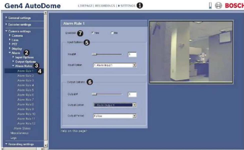
text_image
Gen4 AutoDome LIVEPAGE | RECORDINGS | SETTINGS ① General settings Encoder settings Camera settings Camera Lens PT2 Display Alarm Input Options Output Options Alarm Rules Alarm Rule 1 Alarm Rule 2 Alarm Rule 3 Alarm Rule 4 Alarm Rule 5 Alarm Rule 6 Alarm Rule 7 Alarm Rule 8 Alarm Rule 9 Alarm Rule 10 Alarm Rule 11 Alarm Rule 12 Alarm States Miscellaneous Logs Recording settings Alarm Rule 1 Enabled Yes No Input Options ⑤ Input # 1 Input Option 1 Alarm Input 1 Output Options ⑥ Output # 1 Output Option 1 Alarm Output 1 Output Period Follow help on this page? BOSCHFigure 10.1 Alarm Rules
- Move the slider bar to select a number between 1-4, inclusive.
- Select the appropriate Input Option. This list displays Input Options 1 through 7 only if these options were previously configured.
- Move the slider bar to select a number between 1-4, inclusive.
- Select the appropriate Output Option:
- N o n e
- Output Options 1-3 (only if these options were previously configured).
- Alarm Relay (Output Option 4)
- OSD (on-screen display)
-
T r a n s m i t
-
Select an Output Period:
– Follow: activates the alarm following the alarm rule.
- Time Increment: activates the alarm following a predefined time increment.
- Latched: keeps the alarm active until it is acknowledged.
- Click the Yes radio button to enable the alarm.
Basic Alarm Rule Example
The following is an example for setting up a basic door alarm rule to:
- Flash an OSD message (***ALARM 1***) on the display when the alarm is triggered.
- Move the AutoDome camera to a saved position (for this example use Shot 7).
- Transmit a Bilinx signal over the coax cable to the headend system, such as an Allegiant, to trigger an alarm response.
The sequence to program the above alarm rule is as follows:
- Open the IP AutoDome LIVEPAGE, then click the Settings tab.
- Click the Camera Settings link, click Alarm, expand Input Options, and click Input
Options 1. The IP AutoDome displays the input Options 1 screen.
a. Ensure the drop-down list for Type is set to Alarm Input 1.
b. Click the drop-down list for Alarm Input and set to N.O. (normally open). This setting is the default for Input 1. Additional inputs include:
c. N.C. (Normally Closed, dry contact)
d. N.C.S. (Normally Closed Supervised contact, available only for alarm inputs 1 and 2)
e. N.C.O. (Normally Open Supervised contact, available only for alarm inputs 1 and 2)
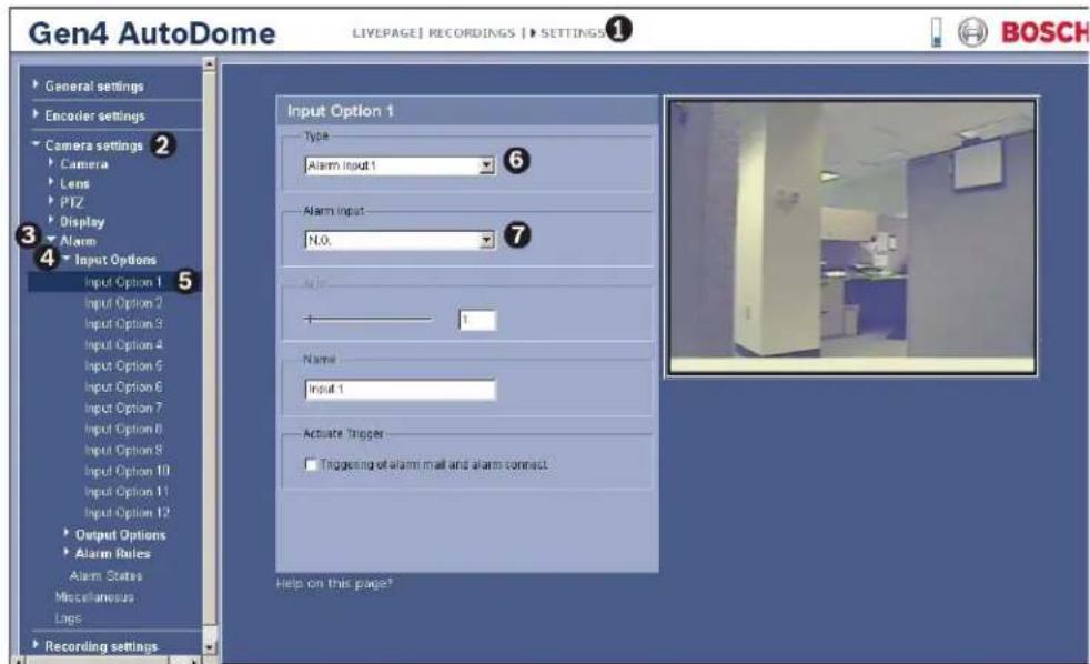
text_image
Gen4 AutoDome LIVEPAGE | RECORDINGS | SETTINGS① General settings Encoder settings Camera settings 2 Camera Lens PTZ Display Alarm Input Options Input Option 1 Input Option 2 Input Option 3 Input Option 4 Input Option 5 Input Option 6 Input Option 7 Input Option 8 Input Option 9 Input Option 10 Input Option 11 Input Option 12 Output Options Alarm Rules Alarm States Miscellaneous Lines Recording settings Input Option 1 Type: Alarm Input 1 Alarm Input: N.0. Name: + - Name: Input 1 Activate Trigger: Triggering of alarm mail and alarm connect Help on this page? BOSCHFigure 10.2 Input Options Settings Example
- Close the Input Options list, then expand the Output Options list. Select Output Option 5.
- Ensure Output 5 is set to OSD (default setting for Output 5).
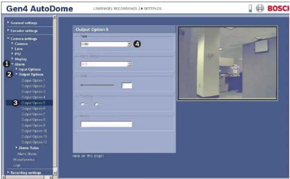
text_image
Gen4 AutoDome LIVEPAGE | RECORDINGS | > SETTINGS General settings Encoder settings Camera settings Camera Lens PTZ Display Alarm Input Options Output Options Output Option 1 Output Option 2 Output Option 3 Output Option 4 Output Option 5 Output Option 6 Output Option 7 Output Option 8 Output Option 9 Output Option 10 Output Option 11 Output Option 12 Alarm Rules Alarm States Miscellaneous Legs Recording settings Output Option 5 Type: 03D 4 Alarm output: No. Shift: - + Timing: OK Cancel Help on this page? Help on this page? BOSCIFigure 10.3 Output Option 5 Example
- Select Output Option 6.
a. Click the Type drop-down list and select Shot.
b. Move the slider bar or type the number 7 in the Shot field.
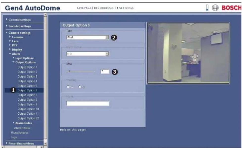
text_image
Gen4 AutoDome LIVEPAGE | RECORDINGS | SETTINGS GENERAL SETTINGS Encoder settings Camera settings Camera Lens PTZ Display Alarm Input Options Output Options Output Option 1 Output Option 2 Output Option 3 Output Option 4 Output Option 5 Output Option 6 Output Option 7 Output Option 8 Output Option 9 Output Option 10 Output Option 11 Output Option 12 Alarm Rules Alarm States Miscellaneous Logs Recording settings Output Option 6 Type: Shot Alarm Output: N.0 Shot 7 Training: On On Name: Help on this page? BOSCHFigure 10.4 Output Option 6 Example
-
Select Output Option 7.
-
Click the Type drop-down list and select Transmit.
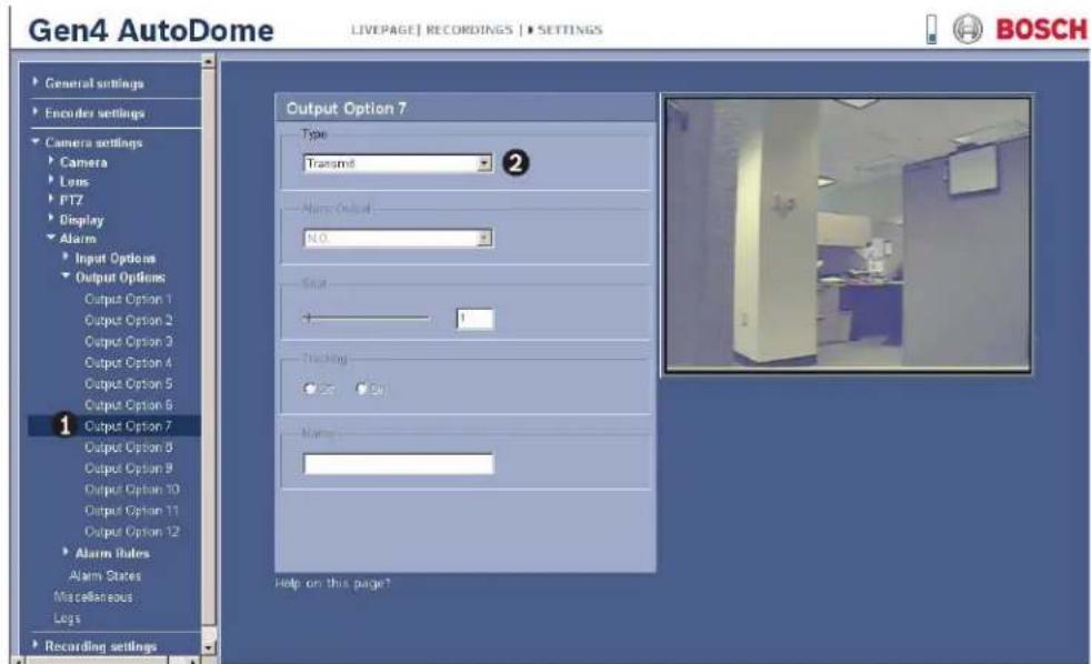
text_image
Gen4 AutoDome LIVEPAGE | RECORDINGS | SETTINGS General settings Encoder settings Camera settings Camera Lens PT7 Display Alarm Input Options Output Options: Output Option 1 Output Option 2 Output Option 3 Output Option 4 Output Option 5 Output Option 6 Output Option 7 Output Option 8 Output Option 9 Output Option 10 Output Option 11 Output Option 12 Alarm Rules Alarm States Miscellaneous Legs Recording settings Output Option 7 Type: Transmit Alarm Output: N.O. Start + - Nicking: - - Name: Help on this page? BOSCHFigure 10.5 Output Option 7 Example
- Close the Output Options list, click Alarm Rules and then click Alarm Rule 1.
a. Move the slider bar or type the number 1 in the Input # field.
b. Click the Input Option drop-down list and select 1: Alarm Input 1.
c. Move the slider bar or type the number 1 in the Output # field.
d. Click the Output Option drop-down list and select 5: OSD.
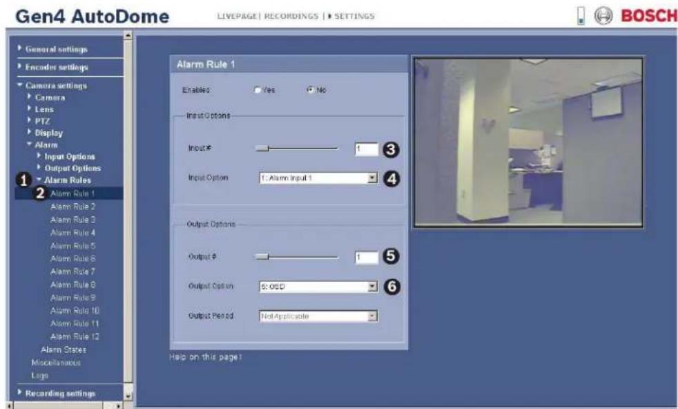
text_image
Gen4 AutoDome LIVEPAGE | RECORDINGS | SETTINGS General settings Encoder settings Camera settings Camera Lens PTZ Display Alarm Input Options Output Options Alarm Rules Alarm Rule 1 Alarm Rule 2 Alarm Rule 3 Alarm Rule 4 Alarm Rule 5 Alarm Rule 6 Alarm Rule 7 Alarm Rule 8 Alarm Rule 9 Alarm Rule 10 Alarm Rule 11 Alarm Rule 12 Alarm States Miscellaneous Logo Recording settings Alarm Rule 1 Enabled Yes No Input Options Input # Input Option 1: Alarm Input 1 Output Options Output # Output Option 6: OSD Output Period Not Applicable Help on this page! BOSCHFigure 10.6 Alarm Rule 1 Example
- Within the Output Options, do the following:
a. Move the slider bar or type the number 1 in the Output # field.
b. Click the Output Option drop-down list and select 5: OSD.
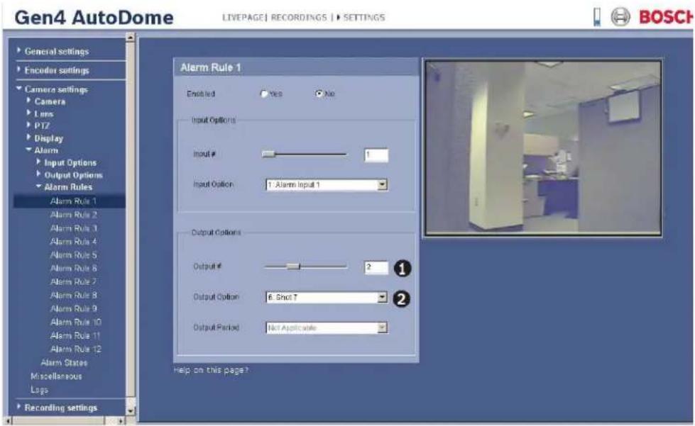
text_image
Gen4 AutoDome LIVEPAGE | RECORDINGS | SETTINGS General settings Encoder settings Camera settings Camera Lens PT2 Display Alarm Input Options Output Options Alarm Rules Alarm Rule 1 Alarm Rule 2 Alarm Rule 3 Alarm Rule 4 Alarm Rule 5 Alarm Rule 6 Alarm Rule 7 Alarm Rule 8 Alarm Rule 9 Alarm Rule 10 Alarm Rule 11 Alarm Rule 12 Alarm States Miscellaneous Logs Recording settings Alarm Rule 1 Enabled Yes No Input Options Input # 1 Input Option 1: Alarm Input 1 Output Options Output # 2 Output Option 6: Shot 7 Output Period Not Applicable Help on this page? BOSCHFigure 10.7 Alarm Rule 1 Example
- Within the Output Options, do the following:
a. Move the slider bar or type the number 3 in the Output # field.
b. Click the Output Option drop-down list and select 7: Transmit.
c. Click the Output Period drop-down list and select 3 sec.
d. Click the Yes radio button to enable Alarm Rule 1.
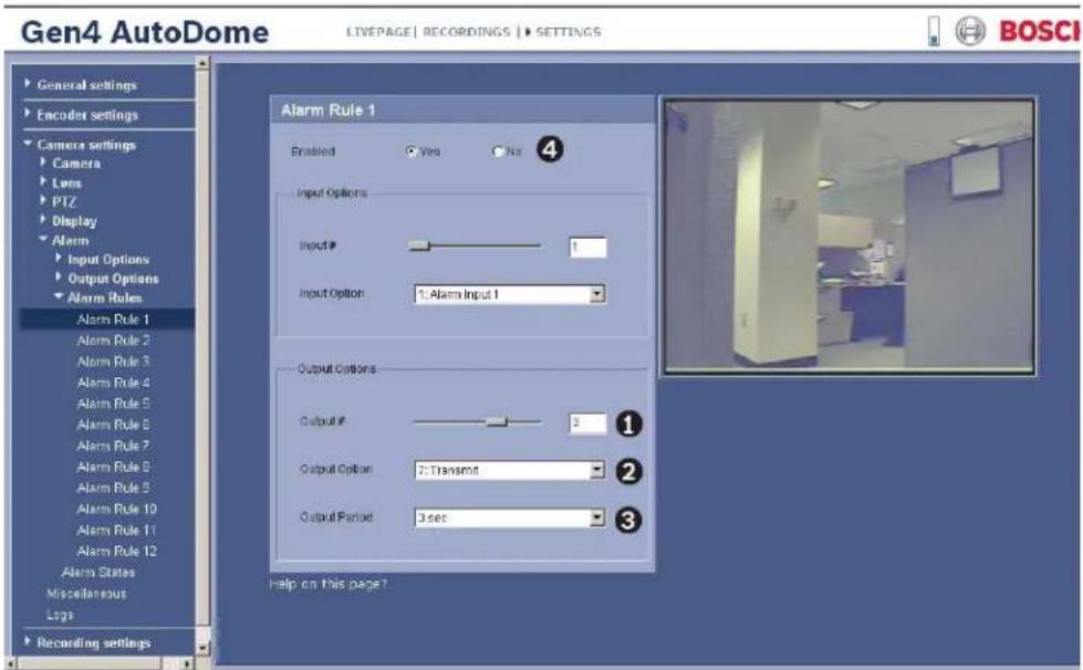
text_image
Gen4 AutoDome LIVEPAGE | RECORDINGS | SETTINGS General settings Encoder settings Camera settings Camera Lens PTZ Display Alarm Input Options Output Options Alarm Rules Alarm Rule 1 Alarm Rule 2 Alarm Rule 3 Alarm Rule 4 Alarm Rule 5 Alarm Rule 6 Alarm Rule 7 Alarm Rule 8 Alarm Rule 9 Alarm Rule 10 Alarm Rule 11 Alarm Rule 12 Alarm States Miscellaneous Logs Recording settings Alarm Rule 1 Enabled Vire Nir 4 Input Options Input # 1 Input Option 1: Alarm Input 1 Output Options Output # 3 Output Option 7: Transmit Output Period 3 sec 1 2 3 help on this page?Figure 10.8 Alarm Rule 1 Example
Advanced Alarm Rule Example using AutoTrack
This example explains how to set an alarm rule that moves the camera to a preset position and then activates the AutoTrack feature to track an intruder after an alarm is triggered.
-
Open the IP AutoDome LIVEPAGE, then click the Settings tab.
-
Click the Camera Settings link, click Alarm, then click Output Options.
-
Click Output Option 5 under the Output Options group.
-
Select Tracking from the Type drop-down list.
-
Click Output Option 6.
-
Select Shot from the Type drop-down list.
-
Type the number 1 or use the slide bar to specify shot number 1. (Shot numbers must be set prior to configuring an alarm rule. See Section 8.6.1 Entering a Keyboard Control Command, page 62, for instructions).
The AutoDome moves to this preposition when the alarm rule is true.
-
Click Alarm Rule link and then click Alarm Rule 1.
-
Click the Yes radio button to enable the rule.
-
Use the slider bar to select 1 for the Input option.
-
Select Alarm Input 1 from the Input Option drop-down list.
-
Ensure that the Output number is set to 1.
-
Select 6: Shot 1 from the Output Options drop-down list. This option instructs the AutoDome to move to pre-position shot 1 when Input 1 is true.
-
Move the Output slider bar to output 2.
-
Select 5:Tracking from the Output Option drop-down list. This option instructs the AutoDome to activate the AutoTrack feature after the input alarm is triggered and after the AutoDome moves to pre-position 1.
-
Select 5 sec from the Output Period drop-down list. This option instructs the AutoDome to turn off the AutoTrack feature after five seconds from when the tracked object is out of view.
10.37 Miscellaneous
Password
A password controls access to locked command menus. Passwords are four (4) digits in length. Two password numbers are reserved:
- 0000: Enables security and requires a user to enter the unlock command OFF-90-ENTER (from a keyboard). This password is the default.
- 9999: Disables all security and allows all users to access locked commands.
To set a password, enter a number between 0000 and 9999, inclusive.
Address
Allows the appropriate dome to be operated via the numerical address in the control system. Type a number between 0000 and 9999, inclusive, to identify the camera.
Baud Rate
Sets the speed at which data is transmitted, measured in bytes-per-second (BPS). The default is 9600.
Auto Baud
Select Yes to instruct the camera to accept baud rates from 2400 to 57600. The default is On.
Audio/BiPhase
Use this option to disable the Audio and to activate the Biphase communication. The default is Biphase.
Reset to Factory Defaults
Click the Reset button to reset the miscellaneous settings to the default settings:
- Password: 0000
- Address: 9999
- Baud Rate: 9600
- AutoBaud: On
– Audio/Biphase: Biphase
10.38 Logs
To save the log file information:
-
Click Download to obtain the log information.
-
Click Save.
-
Navigate to the directory in which you want to store the log information.
-
Type a name for the log file and click Save.
10.39 Advanced Mode: Storage Management
You can record the images from the camera connected to the IP AutoDome on an appropriately configured iSCSI system.
For long-term, authoritative images, it is essential that you use an appropriately sized iSCSI system.
It is also possible to let the VRM Video Recording Manager control all recording when accessing an iSCSI system. This is an external program for configuring recording tasks for video servers. For further information please contact your local customer service at Bosch Security Systems.
Device manager
If you activate the VRM option in this screen, the VRM Video Recording Manager will manage all recording and you will not be able to configure any further settings here.

CAUTION!
Activating or deactivating VRM causes the current settings to be lost; they can only be restored through reconfiguration.
Recording media
Select the required recording media here so that you can then activate them and configure the recording parameters.
iSCSI Media
If you want to use an iSCSI system as a recording medium, you must set up a connection to the required iSCSI system and set the configuration parameters.

NOTICE!
The iSCSI storage system selected must be available on the network and completely set up. Amongst other things, it must have an IP address and be divided into logical drives (LUN).
-
Enter the IP address of the required iSCSI destination in the iSCSI IP address field.
-
If the iSCSI destination is password protected, enter this into the Password field.
-
Click the Read button. The connection to the IP address will be established. In the Storage overview field, you can see the corresponding logical drives.
Local Media
The supported local recording media are displayed in the Storage overview field.
Activating and Configuring Storage Media
The storage overview displays the available storage media. You can select individual media or iSCSI drives and transfer these to the Managed storage media list. You can activate the storage media in this list and configure them for storage.

CAUTION!
Each storage medium can only be associated with one user. If a storage medium is already being used by another user, you can decouple the user and connect the drive with the IP AutoDome. Before decoupling, make absolutely sure that the previous user no longer needs the storage medium.
- In the Recording media section, click the iSCSI Media and Local Media tabs to display the applicable storage media in the overview.
- In the Storage overview section, double-click the required storage medium, an iSCSI LUN or one of the other available drives. The medium is then added to the Managed storage media list. In the Status column, newly added media are indicated by the status Not active.
- Click the Set button to activate all media in the Managed storage media list. In the Status column, these are indicated by the status Online.
- Check the box in the Rec. 1 or Rec. 2 column to specify which data stream should be recorded on the storage media selected. Rec. 1 stores Stream 1, Rec. 2 stores Stream 2. This means that you can record the standard data stream on a hard drive and record alarm images on another drive, for example.
- Check the boxes for the Overwrite older recordings option to specify which older recordings can be overwritten once the available memory capacity has been used. Recording 1 corresponds to Stream 1, Recording 2 corresponds to Stream 2.

CAUTION!
If older recordings are not allowed to be overwritten when the available memory capacity has been used, the recording in question will be stopped. You can specify limitations for overwriting old recordings by configuring the retention time (see Section 10.41 Advanced Mode: Retention Time, page 97).
Formatting Storage Media
You can delete all recordings on a storage medium at any time.

CAUTION!
Check the recordings before deleting and back up important sequences on the computer's hard drive.
- Click a storage medium in the Managed storage media list to select it.
- Click the Edit button below the list. A new window will open.
- Click the Formatting button to delete all recordings in the storage medium.
- Click OK to close the window.
Deactivating Storage Media
You can deactivate any storage medium from the Managed storage media list. It is then no longer used for recordings.
- Click a storage medium in the Managed storage media list to select it.
- Click the Remove button below the list. The storage medium is deactivated and removed from the list.
10.40 Advanced Mode: Recording Profiles
You can define up to ten different recording profiles. You will then use these recording profiles in the recording scheduler, where they are linked with the individual days and times (see Section 10.42 Advanced Mode: Recording Scheduler, page 97).

NOTICE!
You can change or add to the recording profile description on the tabs on the Recording Scheduler page (see Section Time periods, page 98).
- Click one of the tabs to edit the corresponding profile.
- If necessary, click the Default button to return all settings to their default values.
- Click the Copy Settings button if you want to copy the currently visible settings to other profiles. A new window will open and you can select the profiles in which you want to copy the settings.
- For each profile, click the Set button to save the settings in the unit.
Stream profile settings
You can select the profile setting that is to be used for each data stream in the event of recordings. This selection is independent of the selection for live data stream transmission (see Section 10.17 Advanced Mode: Encoder Streams, page 80).
The properties of the profiles are defined on the Encoder Profile page (see Section 10.16 Advanced Mode: Encoder Profile, page 78).
Recording includes
You can specify whether, in addition to video data, audio data and metadata (for example alarms, VCA data and serial data) should also be recorded. Including metadata could make subsequent searches of recordings easier but it requires additional memory capacity.

CAUTION!
Without metadata, it is not possible to include video content analysis in recordings.
Standard recording
Here you can select the mode for standard recordings.
If you select Continuous, the recording proceeds continuously. If the maximum memory capacity is reached, older recordings will automatically be overwritten. If you select the Pre-alarm option, recording will only take place in the pre-alarm time, during the alarm and during the set post-alarm time.
If you select Off, no automatic recording takes place.

CAUTION!
You can specify limitations for overwriting older recordings in Continuous mode by configuring the retention time (see Section 10.41 Advanced Mode: Retention Time, page 97).
Stream
Here you can select the data stream that is to be used for standard recordings. You can select the data stream for alarm recordings separately and independently of this (see Section Alarm stream, page 97).
Pre-alarm time
You can select the required pre-alarm time from the list field.
Post-alarm time
You can select the required post-alarm time from the list field.
Alarm stream
Here you can select the data stream that is to be used for alarm recordings. You can select the data stream for standard recordings separately and independently of this (see Section Stream, page 96).
with encoding interval from profile
You can select an alternative encoding interval for the data stream for alarm recordings. Otherwise the encoding interval that corresponds to the default profile allocated to the data stream is used (see Section 10.17 Advanced Mode: Encoder Streams, page 80).
Alarm input / Motion/Audio alarm / Video loss alarm
Here you can select the alarm sensor that is to trigger a recording.

NOTICE!
The alarm inputs are configured and activated on the Alarm Inputs page (see Section 10.34 Input Options, page 86). The numbering of the checkboxes for the alarm inputs corresponds to the labeling of the alarm inputs on the IP AutoDome. The motion alarm is configured and activated on the VCA page (see Section 10.45 Advanced Mode: VCA, page 101 onwards).
Virtual alarm
Here you can select the virtual alarm sensors that are to trigger a recording, via RCP+ commands or alarm scripts, for example.

NOTICE!
For more information, please see the Alarm Task Script Language document and the RCP+ documentation. These documents can be found on the product CD supplied.
10.41 Advanced Mode: Retention Time
You can specify the retention times for recordings. If the available memory capacity of a medium has been used, older recordings are only overwritten if the retention time entered here has expired.

NOTICE!
Make sure that the retention time corresponds with the available memory capacity. A rule of thumb for the memory requirement is as follows: 1 GB per hour retention time with 4CIF for complete frame rate and high image quality.
Recording 1 / Recording 2
Enter the required retention time in hours or days for each recording. Recording 1 corresponds to Stream 1, Recording 2 corresponds to Stream 2.
10.42 Advanced Mode: Recording Scheduler
The recording scheduler allows you to link the created recording profiles with the days and times at which the camera's images are to be recorded in the event of an alarm.
You can link any number of 15-minute intervals with the recording profiles for each day of the week. Moving the mouse cursor over the table displays the time below it. This aids orientation.
In addition to the normal weekdays, you can define holidays that are not in the standard weekly schedule on which recordings are to apply. This allows you to apply a schedule for Sundays to other days with dates that fall on varying weekdays.
- Click the profile you want to link in the Time periods field.
- Click in a field in the table, hold down the mouse button and drag the cursor over all the periods to be assigned to the selected profile.
- Use the right mouse button to deselect any of the intervals.
- Click the Select All button to link all time intervals to the selected profile.
- Click the Clear All button to deselect all of the intervals.
- When you are finished, click the Set button to save the settings in the unit.
Holidays
You can define holidays that are not in the standard weekly schedule on which recordings are to apply. This allows you to apply a schedule for Sundays to other days with dates that fall on varying weekdays.
- Click the Holidays tab. Any days that have already been selected will be shown in the table.
- Click the Add button. A new window will open.
- Select the desired date from the calendar. You can select several consecutive calendar days by holding down the mouse button. These will later be displayed as a single entry in the table.
- Click OK to accept the selection. The window will close.
- Assign the individual holidays to the recording profiles, as described above.
Deleting Holidays
You can delete holidays you have defined yourself at any time.
- Click the Delete button. A new window will open.
- Click the date you wish to delete.
- Click OK. The item will be deleted from the table and the window will close.
- The process must be repeated for deleting additional days.
Time periods
You can change the names of the recording profiles.
- Click a profile and then the Rename button.
- Enter your chosen name and then click the Rename button again.
Activating the Recording
After completing configuration you must activate the recording scheduler and start the recording. Once recording is underway, the Recording Profiles and Recording Scheduler pages are deactivated and the configuration cannot be modified.
You can stop the recording activity at any time and modify the settings.
- Click the Start button to activate the recording scheduler.
- Click the Stop button to deactivate the recording scheduler. Running recordings are interrupted and the configuration can be changed.
Recording status
The graphic indicates the recording activity of the IP AutoDome. You will see an animated graphic while recording is taking place.
10.43 Advanced Mode: Recording Status
Certain details on the recording status are displayed here for information purposes. You cannot change any of these settings.
10.44 Advanced Mode: Alarm Connections
You can select how the IP AutoDome responds to an alarm. In the event of an alarm, the unit can automatically connect to a pre-defined IP address. You can enter up to ten IP addresses to which the IP AutoDome will connect in sequence in the event of an alarm, until a connection is made.
Connect on alarm
Select On so that the IP AutoDome automatically connects to a predefined IP address in the event of an alarm.
By setting Follows input 1 the unit maintains the connection that has been automatically established for as long as an alarm exists on alarm input 1.

NOTICE!
In the default setting, Stream 2 is transmitted for alarm connections. Bear this fact in mind when assigning the profile (see Section 10.16 Advanced Mode: Encoder Profile, page 78).
Number of destination IP address
Specify the numbers of the IP addresses to be contacted in the event of an alarm. The unit contacts the remote stations one after the other in the numbered sequence until a connection is made.
Destination IP address
For each number, enter the corresponding IP address for the desired remote station.
Destination password
If the remote station is password protected, enter the password here.
In this page, you can save a maximum of ten destination IP addresses and hence up to ten passwords for connecting to remote stations. If connections to more than ten remote stations are to be possible, for example when initiating connections via higher-ranking systems such as VIDOS or Bosch Video Management System, you can store a general password here. The IP AutoDome can use this general password to connect to all remote stations protected with the same password. In this case, proceed as follows:
- Select 10 from the Number of destination IP address list field.
- Enter the address 0.0.0.0 in the Destination IP address field.
- Enter your chosen password in the Destination password field.
- Define this password as the user password for all remote stations to which a connection is to be possible.

NOTICE!
If you enter the destination IP address 0.0.0.0 for destination 10, this address will no longer be used for the tenth attempt at automatic connection in the event of an alarm. The parameter is then used only to save the general password.
| Video transmissionIf the unit is operated behind a firewall, TCP (HTTP port) should be selected as the transfer protocol. For use in a local network, select UDP. | |
 | CAUTION!Please note that in some circumstances, a larger bandwidth must be available on the network for additional video images in the event of an alarm, in case Multicast operation is not possible. To enable Multicast operation, select the UDP option for the Video transmission parameter here and on the Network page (see Page 110). |
| Remote portDepending on the network configuration, select a browser port here. The ports for HTTPS connections will be available only if the On option is selected in the SSL encryption parameter.Video outputIf you know which unit is being used as the receiver, you can select the analog video output to which the signal should be switched. If the destination unit is unknown, it is advisable to select the First available option. In this case, the image is placed on the first free video output. This is an output on which there is no signal. The connected monitor only displays images when an alarm is triggered. If you select a particular video output and a split image is set for this output on the receiver, you can also select from Decoder the decoder in the receiver that is to be used to display the alarm image. | |
 | NOTICE!Refer to the destination unit documentation concerning image display options and available video outputs. |
| DecoderSelect a decoder of the receiver to display the alarm image. The decoder selected has an impact on the position of the image in a split screen. For example, you can specify via a VIP XD that the upper-right quadrant should be used to display the alarm image by selecting decoder 2.SSL encryptionThe data for the connection, for example the password, can be securely transmitted with SSL encryption. If you have selected the On option, only encrypted ports are offered in the Remote port parameter. | |
 | NOTICE!Please note that the SSL encryption must be activated and configured at both ends of a connection. This requires the appropriate certificates to be uploaded onto the IP AutoDome (see Page 116). |
| You can activate and configure encryption of the media data (video, audio and metadata) on the Encryption page (see Section 10.56 Advanced Mode: Encryption, page 115).Auto-connectSelect the On option to automatically re-establish a connection to one of the previously specified IP addresses after each reboot, after a connection breakdown or after a network failure. |

NOTICE!
In the default setting, Stream 2 is transmitted for automatic connections. Bear this fact in mind when assigning the profile (see Section 10.16 Advanced Mode: Encoder Profile, page 78).
Audio
Select the On option if you wish to additionally transmit a standalone G.711 encoded audio stream with alarm connections.
10.45 Advanced Mode: VCA
The IP AutoDome contains an integrated video content analysis (VCA), which can detect and analyze changes in the signal using image processing algorithms. Such changes can be due to movements in the camera's field of view.
You can select various VCA configurations and adapt these to your application as required.
The Silent MOTION+ configuration is active by default. In this configuration, metadata is created to facilitate searches of recordings; however, no alarm is triggered.
You can switch off the video content analysis completely if the device's full power is to be made available for the encoder.
- Select a VCA configuration and make the required settings.
- If necessary, click the Default button to return all settings to their default values.
10.46 Advanced Mode: VCA Profiles
You can configure two profiles with different VCA configurations. You can save profiles on your computer's hard drive and load saved profiles from there. This can be useful if you want to test a number of different configurations. Save a functioning configuration and test new settings. You can use the saved configuration to restore the original settings at any time.

NOTICE!
If computing power becomes short, the highest priority is always the live images and recordings. This can lead to impairment of the video content analysis. You should therefore observe the processor load and optimize the encoder settings or the video content analysis settings as necessary.
- Select a VCA profile and enter the required settings.
- If necessary, click the Default button to return all settings to their default values.
- Click the Save... button to save the profile settings to another file. A new window is opened, in which you can specify where you want to save the file and what name you want to save it under.
- Click the Load... button to load a saved profile. A new window opens in which you can select the profile file and specify where to save the file.
VCA configuration
Select one of the profiles here to activate it or edit it.
You can rename the profile.
-
To rename the file, click the icon to the right of the list field and enter the new profile name in the field.
-
Click the icon again. The new profile name is saved.
Alarm status
The alarm status is displayed here for information purposes. This means you can check the effects of your settings immediately.
Aggregation time (s)
You can set an aggregation time of between 0 and 20 seconds if necessary. The aggregation time always starts when an alarm event occurs. It extends the alarm event by the value set. This prevents alarm events that occur in quick succession from triggering several alarms and successive events in a rapid sequence. No further alarm is triggered during the aggregation time.
The post-alarm time set for alarm recordings only starts once the aggregation time has expired (see Section 10.40 Advanced Mode: Recording Profiles, page 95).
Analysis type
Select the required analysis algorithm. By default, only MOTION+ is available – this offers a motion detector and essential recognition of tampering.

NOTICE!
Additional analysis algorithms with comprehensive functions, such as IVMD and IVA, are available from Bosch Security Systems.
If you select one of these algorithms, you can set the corresponding parameters here directly. You can find information on this in the relevant documents on the product CD supplied.
Metadata is always created for a video content analysis, unless this was explicitly excluded. Depending on the analysis type selected and the relevant configuration, additional information overlays the video image in the preview window next to the parameter settings.
With the MOTION+ analysis type, for example, the sensor fields in which motion is recorded will be marked with rectangles.

NOTICE!
On the LIVEPAGE Functions page, you can also enable additional information overlays for the LIVEPAGE (see Section 10.13 Advanced Mode: LIVEPAGE Functions, page 76).
Motion detector (MOTION+ only)
For the detector to function, the following conditions must be met:
- Analysis must be activated.
- At least one sensor field must be activated.
- The individual parameters must be configured to suit the operating environment and the desired responses.
- The sensitivity must be set to a value greater than zero.

CAUTION!
Reflections of light (off glass surfaces, etc.), switching lights on or off or changes in the light level caused by cloud movement on a sunny day can trigger unintended responses from the motion detector and generate false alarms. Run a series of tests at different times of the day and night to ensure that the video sensor is operating as intended.
For indoor surveillance, ensure constant lighting of the areas during the day and at night.
Sensitivity (MOTION+ only)
The basic sensitivity of the motion detector can be adjusted for the environmental conditions to which the camera is subject.
The sensor reacts to variations in the brightness of the video image. The darker the observation area, the higher the value that must be selected.
Minimum object size (MOTION+ only)
You can specify the number of sensor fields that a moving object must cover to generate an alarm. This is to prevent objects that are too small from triggering an alarm.
A minimum value of 4 is recommended. This value corresponds to four sensor fields.
Debounce time 1 s (MOTION+ only)
The debounce time is intended to prevent very brief alarm events from triggering individual alarms. If the Debounce time 1 s option is activated, an alarm event must last at least 1 second to trigger an alarm.
Select Area (MOTION+ only)
The areas of the image to be monitored by the motion detector can be selected. The video image is subdivided into square sensor fields. Each of these fields can be activated or deactivated individually. If you wish to exclude particular regions of the camera's field of view from monitoring due to continuous movement (by a tree in the wind, etc.), the relevant fields can be deactivated.
- Click Select Area to configure the sensor fields. A new window will open.
- If necessary, click Clear All first to clear the current selection (fields marked yellow).
- Left-click the fields to be activated. Activated fields are marked yellow.
- If necessary, click Select All to select the entire video frame for monitoring.
- Right-click any fields you wish to deactivate.
- Click OK to save the configuration.
- Click the close button X in the window title bar to close the window without saving the changes.
Tamper detection
You can reveal the tampering of cameras and video cables by means of various options. Run a series of tests at different times of the day and night to ensure that the video sensor is operating as intended.

NOTICE!
The options for tamper detection can only be set for fixed cameras. Dome cameras or other motorized cameras cannot be protected in this manner as the movement of the camera itself causes changes in the video image that are too great.
Sensitivity

NOTICE!
This and the following parameter are only accessible if the reference check is activated.
The basic sensitivity of the tamper detection can be adjusted for the environmental conditions to which the camera is subject.
The algorithm reacts to the differences between the reference image and the current video image. The darker the observation area, the higher the value that must be selected.
Trigger delay (s)
You can set delayed alarm triggering. The alarm is only triggered after a set time interval in seconds has elapsed and then only if the triggering condition still exists. If the original condition has been restored before this time interval elapses, the alarm is not triggered. This allows you to avoid false alarms triggered by short-term changes, for example cleaning activities in the direct field of vision of the camera.
Global change
You can set how large the global change in the video image must be for an alarm to be triggered. This setting is independent of the sensor fields selected under Select Area. Set a high value if fewer sensor fields need to change to trigger an alarm. With a low value, it is necessary for changes to occur simultaneously in a large number of sensor fields to trigger an alarm.
This option allows you to detect, independently of motion alarms, manipulation of the orientation or location of a camera resulting from turning the camera mount bracket, for instance.
Global change
Activate this function if the global change, as set with the Global change slide control, should trigger an alarm.
Scene too bright
Activate this function if tampering associated with exposure to extreme light (for instance, shining a flashlight directly on the lens) should trigger an alarm. The average brightness of the scene provides a basis for recognition.
Scene too dark
Activate this function if tampering associated with covering the lens (for instance, by spraying paint on it) should trigger an alarm. The average brightness of the scene provides a basis for recognition.
Scene too noisy
Activate this function if tampering associated with EMC interference (noisy scene as the result of a strong interference signal in the vicinity of the video lines), as an example, should trigger an alarm.
Reference check
You can save a reference image that is continuously compared with the current video image. If the current video image in the marked areas differs from the reference image, an alarm is triggered. This allows you to detect tampering that would otherwise not be detected, for example if the camera is turned.
- Click Reference to save the currently visible video image as a reference.
- Click Select Area and select the areas in the reference image that are to be monitored.
- Check the box Reference check to activate on-going matching. The stored reference image is displayed in black and white below the current video image, and the selected areas are marked in yellow.
- Select the Disappearing edges or Appearing edges option to specify the reference check once again.
Disappearing edges
The area selected in the reference image should contain a prominent structure. If this structure is concealed or moved, the reference check triggers an alarm. If the selected area is too homogenous, so that concealing and moving the structure would not trigger an alarm, then an alarm is triggered immediately to indicate the inadequate reference image.
Appearing edges
Select this option if the selected area of the reference image includes a largely homogenous surface. If structures appear in this area, then an alarm is triggered.
Select Area
You can select the image areas in the reference image that are to be monitored. The video image is subdivided into square fields. Each of these fields can be activated or deactivated individually.

NOTICE!
Select only those areas for reference monitoring in which no movement takes place and that are always evenly lit, as false alarms could otherwise be triggered.
- Click Select Area to configure the sensor fields. A new window will open.
- If necessary, click Clear All first to clear the current selection (fields marked yellow).
- Left-click the fields to be activated. Activated fields are marked yellow.
- If necessary, click Select All to select the entire video frame for monitoring.
- Right-click any fields you wish to deactivate.
- Click OK to save the configuration.
- Click the close button X in the window title bar to close the window without saving the changes.
10.47 Advanced Mode: VCA Scheduled
This configuration allows you to link the created VCA profile with the days and times at which the video content analysis is to be active.
You can link any number of 15-minute intervals with the VCA profiles for each day of the week. Moving the mouse cursor over the table displays the time below it. This aids orientation.
In addition to the normal weekdays, you can define holidays that are not in the standard weekly schedule on which recordings are to apply. This allows you to apply a schedule for Sundays to other days with dates that fall on varying weekdays.
- Click the profile you want to link in the Time periods field.
- Click in a field in the table, hold down the mouse button and drag the cursor over all the periods to be assigned to the selected profile.
- Use the right mouse button to deselect any of the intervals.
- Click the Select All button to link all time intervals to the selected profile.
- Click the Clear All button to deselect all of the intervals.
- When you are finished, click the Set button to save the settings in the unit.
Holidays
You can define holidays on which a profile should be active that are different to the standard weekly schedule. This allows you to apply a schedule for Sundays to other days with dates that fall on varying weekdays.
- Click the Holidays tab. Any days that have already been selected will be shown in the table.
- Click the Add button. A new window will open.
- Select the desired date from the calendar. You can select several consecutive calendar days by holding down the mouse button. These will later be displayed as a single entry in the table.
- Click OK to accept the selection. The window will close.
- Assign the individual holidays to the VCA profiles, as described above.
Deleting Holidays
You can delete holidays you have defined yourself at any time.
- Click the Delete button. A new window will open.
- Click the date you wish to delete.
- Click OK. The item will be deleted from the table and the window will close.
- The process must be repeated for deleting additional days.
10.48 Advanced Mode: VCA Event triggered
This configuration allows you stipulate that the video content analysis is only to be activated when triggered by an event. As long as no trigger is activated, the Silent MOTION+ configuration in which metadata is created is active; this metadata facilitates searches of recordings, but does not trigger an alarm.
Trigger
You can select one of the physical alarms on the device's alarm inputs or one of the virtual alarms as a trigger. A virtual alarm is created using software, with RCP+ commands or alarm scripts, for example.

NOTICE!
For more information, please see the Alarm Task Script Language document and the RCP+ documentation.
Trigger active
Select the VCA configuration here that is to be enabled via an active trigger. A green check mark to the right of the list field indicates that the trigger is active.
Trigger inactive
Select the VCA configuration here that is to be activated if the trigger is not active. A green check mark to the right of the list field indicates that the trigger is inactive.
Delay (s)
Select the delay period here for the reaction of the video content analysis to trigger signals. The alarm is only triggered after a set time interval in seconds has elapsed and then only if the triggering condition still exists. If the original condition has been restored before this time interval elapses, the alarm is not triggered. A delay period may be useful in avoiding false alarms or frequent triggering, for example. During the delay period, the Silent MOTION+ configuration is always enabled.
10.49 Advanced Mode: Audio Alarm
The IP AutoDome can create alarms on the basis of audio signals. You can configure signal strengths and frequency ranges in such a way that false alarms, for example due to machine noise or background noise, are avoided.

NOTICE!
First set up normal audio transmission before you configure the audio alarm here (see Section 10.18 Advanced Mode: Audio, page 80).
Audio alarm
Select On if you want the device to generate audio alarms.
Name
The name makes it easier to identify the alarm in extensive video monitoring systems, for example with the VIDOS and Bosch Video Management System programs. Enter a unique and clear name here.

CAUTION!
Do not use any special characters, for example &, in the name.
Special characters are not supported by the system's internal recording management and may therefore result in the Player or Archive Player being unable to play back the recording.
Threshold
Set up the threshold on the basis of the signal visible in the graphic You can set the threshold using the slide control or, alternatively, you can move the white line directly in the graphic using the mouse.
Sensitivity
You can use this setting to adapt the sensitivity to the sound environment. You can effectively suppress individual signal peaks. A high value represents a high level of sensitivity.
Signal Ranges
You can exclude particular signal ranges in order to avoid false alarms. For this reason the total signal is divided into 13 tonal ranges (mel scale). Check or uncheck the boxes below the graphic to include or exclude individual ranges.
10.50 Advanced Mode: Alarm E-Mail
As an alternative to automatic connecting, alarm states can also be documented by e-mail. In this way it is possible to notify a recipient who does not have a video receiver. In this case, the IP AutoDome automatically sends an e-mail to a previously defined e-mail address.
Send alarm e-mail
Select On if you want the unit to automatically send an alarm e-mail in the event of an alarm.
Mail server IP address
Enter the IP address of a mail server that operates on the SMTP standard (Simple Mail Transfer Protocol). Outgoing e-mails are sent to the mail server via the address you entered. Otherwise leave the box blank (0.0.0.0).
SMTP user name
Enter a registered user name for the chosen mailserver here.
SMTP password
Enter the required password for the registered user name here.
Format
You can select the data format of the alarm message.
- Standard (with JPEG)
E-mail with attached JPEG image file.
- SMS
E-mail in SMS format to an e-mail-to-SMS gateway (for example to send an alarm by cellphone) without an image attachment.

CAUTION!
When a cellphone is used as the receiver, make sure to activate the e-mail or SMS function, depending on the format, so that these messages can be received.
You can obtain information on operating your cellphone from your cellphone provider.
Attach JPEG from camera
Click the checkbox to specify that JPEG images are sent from the camera. An enabled video input is indicated by a check mark.
Destination address
Enter the e-mail address for alarm e-mails here. The maximum address length is 49 characters.
Sender name
Enter a unique name for the e-mail sender, for example the location of the unit. This will make it easier to identify the origin of the e-mail.
Test e-mail
You can test the e-mail function by clicking the Send Now button. An alarm e-mail is immediately created and sent.
10.51 Advanced Mode: Alarm Task Editor

CAUTION!
Editing scripts on this page overwrites all settings and entries on the other alarm pages. This procedure cannot be reversed.
In order to edit this page, you must have programming knowledge and be familiar with the information in the Alarm Task Script Language document.
As an alternative to the alarm settings on the various alarm pages, you can enter your desired alarm functions in script form here. This will overwrite all settings and entries on the other alarm pages.
- Click the Examples link under the Alarm Task Editor field to see some script examples. A new window will open.
- Enter new scripts in the Alarm Task Editor field or change existing scripts in line with your requirements.
- When you are finished, click the Set button to transmit the scripts to the unit. If the transfer was successful, the message Script successfully parsed is displayed over the text field. If it was not successful, an error message will be displayed with further information.
10.52 Advanced Mode: Network
The settings on this page are used to integrate the IP AutoDome into an existing network. Some changes only take effect after the unit is rebooted. In this case, the Set button changes to Set and Reboot.
- Make the desired changes.
- Click the Set and Reboot button. The IP AutoDome is rebooted and the changed settings are activated.

CAUTION!
If you change the IP address, subnet mask or gateway address, the IP AutoDome is only available under the new addresses after the reboot.
Automatic IP assignment
If a DHCP server is employed in the network for the dynamic assignment of IP addresses, you can activate acceptance of IP addresses automatically assigned to the IP AutoDome.
Certain applications (VIDOS, Bosch Video Management System, Archive Player, Configuration Manager) use the IP address for the unique assignment of the unit. If you use these applications, the DHCP server must support the fixed assignment between IP address and MAC address, and must be appropriately set up so that, once an IP address is assigned, it is retained each time the system is rebooted.
IP address
Enter the desired IP address for the IP AutoDome in this field. The IP address must be valid for the network.
Subnet mask
Enter the appropriate subnet mask for the selected IP address here.
Gateway address
If you want the unit to establish a connection to a remote location in a different subnet, enter the IP address of the gateway here. Otherwise leave the box blank (0.0.0.0).
DNS server address
The unit can use a DNS server to trigger an address specified as a name. Enter the IP address of the DNS server here.
Video transmission
If the unit is operated behind a firewall, TCP (HTTP port) should be selected as the transfer protocol. For use in a local network, select UDP.

CAUTION!
Multicast operation is only possible with the UDP protocol. The TCP protocol does not support multicast connections.
The MTU value in UDP mode is 1,514 bytes.
HTTP browser port
Select a different HTTP browser port from the list if required. The default HTTP port is 80. If you want to allow only secure connections via HTTPS, you must deactivate the HTTP port. In this case, select Off.
HTTPS browser port
If you wish to allow browser access on the network via a secure connection, select an HTTPS browser port from the list if necessary. The default HTTPS port is 443. Select the Off option to deactivate HTTPS ports; only unsecured connections will now be possible.
The IP AutoDome uses the TLS 1.0 encryption protocol. You may have to activate this protocol via your browser configuration. You must also activate the protocol for the Java applications (via the Java control panel in the Windows control panel).

NOTICE!
If you want to allow only secure connections with SSL encryption, you must select the Off option for each of the parameters HTTP browser port, RCP+ port 1756 and Telnet support. This deactivates all unsecured connections. Connections will then only be possible via the HTTPS port.
You can activate and configure encryption of the media data (video, audio and metadata) on the Encryption page (see Section 10.56 Advanced Mode: Encryption, page 115).
RCP+ port 1756
To exchange connection data, you can activate the unsecured RCP+ port 1756. If you want connection data to be transmitted only when encrypted, select the Off option to deactivate the port.
Telnet support
If you want to allow only secure connections with encrypted data transmission, you must select the Off option to deactivate Telnet support. The unit will then no longer be accessible using the Telnet protocol.
Interface mode ETH
If necessary, select the Ethernet link type for the ETH interface. Depending on the unit connected, it may be necessary to select a special operation type.
Network MSS (Byte)
You can set the maximum segment size for the IP packet's user data. This gives you the option to adjust the size of the data packets to the network environment and to optimize data transmission. Please comply with the MTU value of 1,514 bytes in UDP mode.
iSCSI MSS (Byte)
You can specify a higher MSS value for a connection to the iSCSI system than for the other data traffic via the network. The potential value depends on the network structure. A higher value is only useful if the iSCSI system is located in the same subnet as the IP AutoDome.
Enable DynDNS
DynDNS.org is a DNS hosting service that stores IP addresses in a database ready for use. It allows you to select the IP AutoDome via the Internet using a host name, without having to know the current IP address of the unit. You can enable this service here. To do this, you must have an account with DynDNS.org and you must have registered the required host name for the unit on that site.

NOTICE!
Information about the service, registration process and available host names can be found at DynDNS.org.
Host name
Enter the host name registered on DynDNS.org for the IP AutoDome here.
User name
Enter the user name you registered at DynDNS.org here.
Password
Enter the password you registered at DynDNS.org here.
Force registration now
You can force the registration by transferring the IP address to the DynDNS server. Entries that change frequently are not provided in the Domain Name System. It is a good idea to force the registration when you are setting up the device for the first time. Only use this function when necessary and no more than once a day, to avoid the possibility of being blocked by the service provider. To transfer the IP address of the IP AutoDome, click the Register button.
Status
The status of the DynDNS function is displayed here for information purposes. You cannot change any of these settings.
10.53 Advanced Mode: Advanced
The settings on this page are used to implement advanced settings for the network.
Some changes only take effect after the unit is rebooted. In this case, the Set button changes
to Set and Reboot.
-
Make the desired changes.
-
Click the Set and Reboot button. The IP AutoDome is rebooted and the changed settings are activated.
SNMP
The IP AutoDome supports the SNMP V2 (Simple Network Management Protocol) for managing and monitoring network components, and can send SNMP messages (traps) to IP addresses. The unit supports SNMP MIB II in the unified code. If you wish to send SNMP traps, enter the IP addresses of one or two required target devices here.
If you select On for the SNMP parameter and do not enter an SNMP host address, the IP AutoDome does not send them automatically, but only replies to SNMP requests. If you enter one or two SNMP host addresses, SNMP traps are sent automatically. Select Off to deactivate the SNMP function.
1. SNMP host address / 2. SNMP host address
If you wish to send SNMP traps automatically, enter the IP addresses of one or two required target units here.
SNMP traps
You can select which traps are to be sent.
-
Click Select. A list is opened.
-
Click the checkboxes to select the required traps. All the checked traps will be sent.
-
Click Set to accept the selection.
Authentication
If a RADIUS server is employed in the network for managing access rights, authentication must be activated here to allow communication with the unit. The RADIUS server must also contain the corresponding data.
To configure the unit, you must connect the IP AutoDome directly to a computer using a network cable. This is because communication via the network is not enabled until the Identity and Password parameters have been set and successfully authenticated.
Identity
Enter the name that the RADIUS server is to use for identifying the IP AutoDome.
Password
Enter the password that is stored in the RADIUS server.
RTSP port
If necessary, select a different port for the exchange of the RTSP data from the list. The standard RTSP port is 554. Select Off to deactivate the RTSP function.
NTCIP
Specifies a set of rules and protocols for organizing, describing and exchanging transportation management information between transportation management applications and transportation equipment such that they interoperate with each other. Select a port for NTCIP and the Address from the appropriate drop-down lists.
10.54 Advanced Mode: Multicasting
In addition to a 1:1 connection between an encoder and a single receiver (unicast), the IP AutoDome can enable multiple receivers to receive the video signal from an encoder simultaneously. The device either duplicates the data stream itself and then distributes it to multiple receivers (Multi-unicast) or it sends a single data stream to the network, where the data stream is simultaneously distributed to multiple receivers in a defined group (Multicast). You can enter a dedicated multicast address and port for each stream. You can switch between the streams by clicking the appropriate tabs.

NOTICE!
Multicast operation requires a multicast-enabled network that uses the UDP and the Internet Group Management IGMP protocols. Other group management protocols are not supported. The TCP protocol does not support multicast connections.
A special IP address (class D address) must be configured for multicast operation in a multicast-enabled network.
The network must support group IP addresses and the Internet Group Management Protocol (IGMP V2). The address range is from 225.0.0.0 to 239.255.255.255.
The multicast address can be the same for multiple streams. However, it will be necessary to use a different port in each case so that multiple data streams are not sent simultaneously using the same port and multicast address.

NOTICE!
The settings must be made individually for each stream.
Enable
To enable simultaneous data reception on several receivers you need to activate the multicast function. To do this, check the box. You can then enter the multicast address.
Multicast Address
Enter a valid multicast address for each stream to be operated in multicast mode (duplication of the data streams in the network).
With the setting 0.0.0.0 the encoder for the relevant stream operates in multi-unicast mode (copying of data streams in the unit). The IP AutoDome supports multi-unicast connections for up to five simultaneously connected receivers.

NOTICE!
Duplication of data places a heavy demand on the unit and can lead to impairment of the image quality under certain circumstances.
Port
Assign a different port to each data stream if there are simultaneous data streams at the same multicast address.
Enter the port address of the required stream here.
Streaming
Click the checkbox to activate multicast streaming mode for the relevant stream. An enabled stream is indicated by a check mark.
Streaming is typically not required for standard multicast operation.
Multicast packet TTL
You can enter a value to specify how long the multicast data packets are active on the network. This value must be greater than one if multicast is to be run via a router.
10.55 Advanced Mode: JPEG Posting
You can save individual JPEG images on an FTP server at specific intervals. You can then retrieve these images at a later date to reconstruct alarm events if required.
Image size
Select the resolution you wish the JPEG images to have:
- Medium
$$ 3 5 2 \times 2 8 8 / 2 4 0 \text { pixels (CIF) } $$
- Large
$$ 7 0 4 \times 5 7 6 / 4 8 0 \text { pixels (4CIF) } $$
File name
You can select how file names will be created for the individual images that are transmitted.
- Overwrite
The same file name is always used and any existing file will be overwritten with the current file.
- Increment
A number from 000 to 255 is added to the file name and automatically incremented by 1. When it reaches 255 it starts again from 000.
- Date/time suffix
The date and time are automatically added to the file name. When setting this parameter, ensure that the unit's date and time are always correctly set. Example: the file snap011005_114530.jpg was stored on October 1, 2005 at 11:45 and 30 seconds.
Posting interval
Enter the interval in seconds at which the images will be sent to an FTP server. Enter zero if you do not want any images to be sent.
FTP server IP address
Enter the IP address of the FTP server on which you wish to save the JPEG images.
FTP server login
Enter your login name for the FTP server.
FTP server password
Enter the password that gives you access to the FTP server.
Path on FTP server
Enter the exact path on which you wish to post the images on the FTP server.

NOTICE!
The creation of JPEG images has a lower priority than video encoding and image analysis. This can result in JPEG images being created with a delay of up to several seconds after the triggering event. If reliable, real-time recording of the alarm is required, ensure that the encoder has enough computing power available.
10.56 Advanced Mode: Encryption
A special license, with which you will receive a corresponding activation key, is required to encrypt user data. You can enter the activation key to release the function on the Licenses page (see Section 10.58 Advanced Mode: Licenses, page 116).
10.57 Advanced Mode: Maintenance
Firmware
The IP AutoDome is designed in such a way that its functions and parameters can be updated with firmware. To do this, transfer the current firmware package to the unit via the selected network. It will then be automatically installed there. In this way, an IP AutoDome can be serviced and updated remotely without a technician having to change the installation on site. You obtain the current firmware and the detailed VG4 Firmware Update Manual from customer service or from the download area at www.boschsecurity.com.

CAUTION!
Before launching the firmware upload make sure that you have selected the correct upload file. Uploading the wrong files can result in the unit no longer being addressable, in which case you must replace the unit. You should never interrupt the installation of firmware. An interruption can lead to the flash-EPROM being incorrectly programmed. This in turn can result in the unit no longer being addressable, in which case it will have to be replaced. Even changing to another page or closing the browser window leads to an interruption. Refer to the VG4 Firmware Update Manual (available on www.boschsecurity.com) for complete instructions.
Configuration
You can save configuration data for the IP AutoDome on a computer and then load saved configuration data from a computer to the unit.
Upload
- Enter the full path of the file to upload or click Browse to select the required file.
- Make certain that the file to be loaded comes from the same unit type as the unit you want to configure.
- Next, click Upload to begin transferring the file to the unit. The progress bar allows you to monitor the transfer.
Once the upload is complete, the new configuration is activated. The time remaining is shown by the message going to reset Reconnecting in ... seconds. The unit reboots automatically once the upload has successfully completed.
Download
- Click the Download button. A dialog box opens.
- Follow the on-screen instructions to save the current settings.
SSL certificate
To be able to work with an SSL encrypted data connection, both ends of a connection must hold the relevant certificates. You can upload the SSL certificate, comprising one or multiple files, onto the IP AutoDome.
If you wish to upload multiple files onto the IP AutoDome, you must select them consecutively.
- Enter the full path of the file to upload or click Browse to select the required file.
- Next, click Upload to begin transferring the file to the unit.
- Once all files have been successfully uploaded, the unit must be rebooted. In the address bar of your browser, enter /reset after the IP address of the IP AutoDome (for example 192.168.0.10/reset).
The new SSL certificate is valid.
Maintenance log
You can download an internal maintenance log from the unit to send it to Customer Service for support purposes. Click Download and select a storage location for the file.
10.58 Advanced Mode: Licenses
You can enter the activation key to release additional functions or software modules.

NOTICE!
The activation key cannot be deactivated again and is not transferable to other units.
10.59 Advanced Mode: System Overview
The data on this page are for information purposes only and cannot be changed. Keep a record of this information in case technical assistance is required.

NOTICE!
You can select all required text on this page with the mouse and copy it to the clipboard with the [Ctrl]+[C] key combination, for example if you want to send it via e-mail.
11 Troubleshooting Guide
11.1 VG4 AutoDome Operation and Control
| Problem Solution | |
| No video | - Check that the Green LED on the AutoDome CPU board is on. This LED indicates video from the camera.If the Green LED is off, then:- Check that the Red LED on the AutoDome CPU board is slowly blinking. This LED indicates power to the AutoDome power supply board and to the CPU Module.Red LED on AutoDome CPU M0.oduleFlash SequenceIndicates:- 5 sec. on / 0.5 sec. off: Normal operation- Steady on: CPU is lockedIf the Red LED is on steady, then:- Try cycling the AutoDome power off and on.If the Red LED is off, then:If using a Bosch Pendant Power Supply Box:- Check that Green LED in Power Supply Box is on. This LED indicates mains power through the transformer.If the Green LED is off, then:- Turn off the Power.- Check the FX101 fuse for mains power to the Power Supply Box.If O.K., then:- Check the FX102 fuse for 24 V power to the AutoDome Pendant.If O.K., then:If using a non-Bosch power supply:- Check that the mains power to the power supply box is on.If O.K., then:- Check that there is 24 V output from the transformer.- Check the connector on top of the AutoDome housing for bent pins.If O.K., then:- Check the integrity of all wires and terminal connections to the AutoDome.If O.K., then:If there is power to the AutoDome, then:- Remove the camera and CPU modules from the AutoDome housing and check that the Green LED on the housing power supply board is on.If the Green LED is off, then:- Check that the fuse on the housing power supply board is good. (Try replacing the unit, if an extra camera module is available.) |
| No camera control | - Ensure that the keyboard and monitor are set to the correct (same) camera number.If O.K., then:- Check that the camera address is properly set. EnterON-997-ENTERto display the camera address.If address is not set or is incorrect, then:- Set the camera address using FastAddress (ON-998-ENTER).If O.K., then:- Check that the Amber LED on the AutoDome CPU turns on when receiving pan/tilt commands from the controller keyboard. The Amber LED indicates control is being received.Amber LED on AutoDome CPU ModuleFlash Sequence- OffNo incoming communications or no power- Solid for 2 secondsReceiving good data- Fast blinkingLost packet(s)If amber LED does not light when given PTZ commands, then:- Check if other cameras on the system can be controlled. If not, check the controller and wiring connections.If O.K., then:- Check that the RS-232/485 selector switch is properly set to the proper protocol.If O.K., then:- Ensure that all Biphase, Bilinx, or RS-232/485 wires are properly connected. See theAutoDome Modular Camera System Installation Manual.If O.K., then:- Check if you can access the AutoDome OSD menus (ON-46-ENTER).If O.K., then:- Confirm that the AutoDome passes homing (SET-110-ENTER).If AutoDome fails homing, then:- Contact Bosch Technical Support. |
| Intermittent camera control | - Check that only the last AutoDome in a daisy chain configuration is terminated with a 110 Ω resistor across the +/-biphase terminals.If O.K., then:- Check that the maximum wire distance has not been exceeded for the control protocol (the maximum distance for RS-232 is 50 feet). See theAutoDome Modular Camera System Installation Manual.If O.K., then:- Check that all wiring meets Bosch recommended standards and specifications. See theAutoDome Modular Camera System Installation Manual. |
| Camera moves when moving other cameras | - Check that the camera address is properly set (ON-997-ENTER). If the camera address is not set, the AutoDome responds to control commands to any camera on the system.If camera address is not set, then:- Invoke theFastAddress Menuto assign a camera address (ON-998-ENTER). |
| Cannot access user settings | - Enter the unlock commandOFF-90-ENTER. This command may require a password. (Commands automatically lock in 30 minutes.) |
| Setting FastAddress with an American Dynamics Keyboard | The FastAddress value must match the Unique Identifier for the AutoDome. To set the FastAddress on an American Dynamics keyboard refer to Section 4.1 Setting FastAddress with Alternative Protocols, page 33. |
| Picture is dark | - Check that the Gain Control is set to AUTO (ON-43-ENTER).If O.K., then:- Check that the Auto Iris Level is set to the appropriate level (ON-11-ENTER).If O.K., then:- Check that the video coax is terminated with 75 Ω only at the head end. (Double termination causes dark video.)If O.K., then:- Go to the Camera Setup Menu and increase the Pre-Compensation setting. (This feature is available only on 300 and 500i non-IP Series AutoDomes).If O.K., then:- Check that the camera lens cover is removed.If O.K., then:- Check that the maximum coax distance has not been exceeded. See the AutoDome Modular Camera System Installation Manual.If O.K., then:- Restore all camera settings (ON-40-ENTER). |
| Colors are not correct | - Reset the White Balance to the appropriate selection (ON-30-ENTER).If O.K., then:- Go to the Camera Setup Menu and increase the Pre-Compensation setting. (This feature is available only on 300 and 500i non-IP Series AutoDomes).If O.K., then:- Check that the maximum coax distance has not been exceeded. See the AutoDome Modular Camera System Installation Manual.If O.K., then:- Restore the default settings (ON-40-ENTER). |
| Background is too bright to see subject | - Turn on backlight compensation (ON-20-ENTER). |
| Video is rolling, noisy or distorted | - Ensure that the Synch Mode is set to Internal (OFF-42-ENTER).If O.K., then:- Check that the maximum coax distance has not been exceeded. See the AutoDome Modular Camera System Installation Manual.If O.K., then:- Check the integrity of all BNC connectors and splices.Note: Connecting a network cable to the interface board of a non-IP AutoDome causes video distortion.- Remove the network cable from the interface board RJ-45 connector.If O.K., then:- Contact Bosch Technical Support. |
| Day/Night camera does not switch automatically when image is dark | - Check that the Day/Night mode is set to AUTO (ON-56-ENTER).If O.K., then:- Set Gain Control to AUTO (ON-43-ENTER). |
| Inside of EnviroDome bubble is foggy | - Check the status of the Heater Module (ON-66-ENTER).If status reports Heater No Power, then:- Turn off the power to the AutDome.- Check the FX103 fuse in the Power Supply Box for power (24 V) to the heater module.If O.K., then:- Check all wiring and connector pins to the heater module. |
| Low Voltage flashing on monitor display | - If using a non-Bosch power supply, confirm that it meets the Bosch AutoDome power ratings. See the AutoDome Datasheet for specifications.If O.K., then:- Check the mains input line voltage.If O.K., then:- Check that the maximum wire length from the power supply has not been exceeded.See the AutoDome Modular Camera System Installation Manual.If O.K., then:- Measure the AC voltage input to the camera while power is applied to the camera. The voltage must be ≥ 21 VAC to stop the message. |
11.2 VG4 IP AutoDome Video and Control
| Problem Solution | |
| No Network Connection | – Check all network connections– Ensure that the maximum distance between any two Ethernet connections is 100 m (328 ft) or less.Refer to the AutoDome Modular Camera System Installation Manual for more information.If O.K., then:– If you are behind a firewall, ensure that the Video Transmission mode is set to UDP.a. Access the Settings Web page for the IP-enabled device.b. Expand the Service Settings link, then click Network.c. Select UDP from the Video Transmission drop-down list. Then click Set. |
11.3 VG4 IP AutoDome Audio
The following diagrams illustrate the path for audio transmissions between a microphone/AutoDome and a computer that plays the audio. The first diagram illustrates these connections with an IP-enabled VG4 AutoDome and the second illustration uses an analog (standard) VG4 AutoDome. Use the appropriate diagram to help troubleshoot any audio issues.
Audio Connections with an IP-enabled VG4 AutoDome
The IP-enabled AutoDome uses an Ethernet connection to connect directly to an existing network.
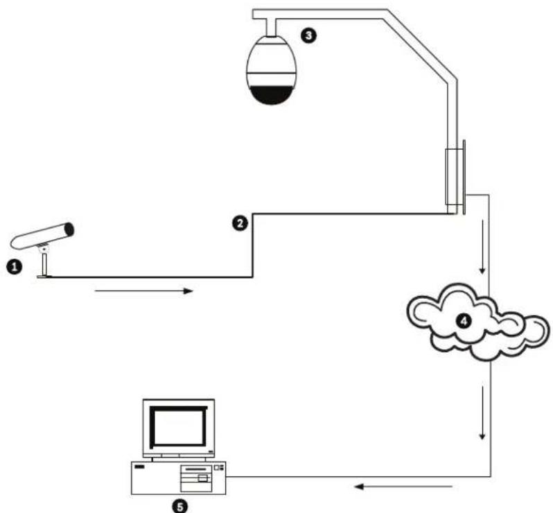
flowchart
graph TD
    A["Sensor ①"] --> B["Signal Line"]
    B --> C["Measurement Unit ②"]
    C --> D["Cloud Cloud ④"]
    D --> E["Computer"]
    E --> F["Monitor ⑤"]
    F --> G["Monitoring Unit ③"]
Figure 11.1 Typical Audio Connections for an IP-enabled AutoDome
| 1 | M i c r o p h o n e |
| 2 | Coaxial Cable-10 m (33 ft) maximum distance |
| 3 | VG4 IP-enabled AutoDome |
| 4 | Ethernet Network |
| 5 | Computer with Bosch DiBos Software |
Audio Connections with an Analog (standard) VG4 AutoDome
In this illustration the analog VG4 AutoDome connects to a Bosch Video/Audio IP Encoder via a coaxial cable. The computer that plays the audio is connected to the encoder via an Ethernet cable.
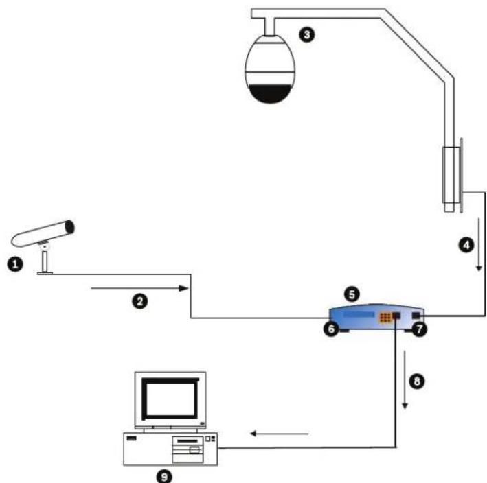
flowchart
graph TD
    A["①"] --> B["②"]
    B --> C["③"]
    C --> D["④"]
    D --> E["⑤"]
    E --> F["⑥"]
    F --> G["⑦"]
    G --> H["⑧"]
    H --> I["⑨"]
    I --> J["Computer"]
Figure 11.2 Typical Audio Connections for an Analog AutoDome
| 1 Microphone 6 Audio In | ||
| 2 Coaxial Connection; Microphone to Bosch Video/Audio Encoder;10 m (33 ft) maximum distance | 7 | V i d e o l n |
| 3 VG4 Analog (Standard) AutoDome 8 Ethernet | Connection;Bosch Video/Audio Encoder to a PC | |
| 4 Coaxial Connection; VG4 AnalogAutodome to a Bosch Video/AudioEncoder | 9 Computer with Bosch DiBos Software | |
| 5 Bosch Video/Audio Encoder | ||
| Problem Solution | |
| No Audio | - Check the computer receiving the audio from the VG4 AutoDome or from the IP Encoder.- Check the computer's audio settings. Ensure that the sound levels are at an audible level.- Check the computer's audio output card and speakers. Play a secondary source of audio on the computer. If you still do not hear audio replace the speakers and try again. |
| If O.K., then:- Ensure that the Audio option is enabled for the IP device.a. Access the Settings Web page for the IP-enabled device.b. Expand the Encoder Settings link, then click Audio Settings.c. Ensure that On is selected from the Enable Audio drop-down list. Then, click Set. | |
| If O.K., then:- Check the microphone.Connect appropriate speakers directly to the microphone at the camera site and confirm that the audio is clear and audible at the location.An audio problem or noise at the source will further degrade as it travels through all the cables and connections. | |
| If O.K., then:- Verify the cable type and installation used for audio connections between the microphone and the VG4 AutoDome.- Cable type: Coaxial- Cable length: 10 m (33 ft), maximumRefer to the AutoDome Modular Camera System Installation Manual for more information.If O.K., then:– Check all network connections.– If the video is clear and contains no distortion, then the network connections are probably not the source of audio problems.– Ensure that the maximum distance between any two Ethernet connections is 100 m (328 ft).Refer to the AutoDome Modular Camera System Installation Manual for more information. | |
| Poor Audio | – Check the computer receiving the audio from the VG4 AutoDome or from the IP Decoder.– Check the computer's audio output card and speakers. Play a secondary source of audio on the computer, if you hear static then replace the speakers and try again.– Check the computer's audio output card and speakers. Play a secondary source of audio on the computer. If you still do not hear audio replace the speakers and try again.If O.K., then:– Check the Gain settings and the peak gain value.a. Access the Settings Web page for the IP-enabled device.b. Expand the Encoder Settings link, then click Audio Settings.c. Adjust the Gain level so that the peak value stays within the green area.Refer to the AutoDome Modular Camera System Installation Manual for complete information.If O.K., then:– Check the location of the microphone and the audio cables.– Line level audio is typically between 700 mV and 2 V so it may be affected by AC power or transmission sources.– Ensure that there is a maximum (at least 1 foot per 100 VAC) distance between the microphone and audio cables and the AC source.If O.K., then:– Verify the cable type and installation used for audio connections between the microphone and the VG4 AutoDome.– Cable type: Coaxial– Cable length: 10 m (33 ft), maximumRefer to the AutoDome Modular Camera System Installation Manual for more information. |
12 User Command Table
| Function Key | Comm No. | Command Description Series | 200 | Series 300 | Series 500i | |
| On/Off 1 | Scan 360° | Autopan without limits * | * * | |||
| On/Off 2 | Autopan Autopan between limits * | * * | ||||
| On/Off 7 | Play Custom Pre-position Tour | Activate/Deactivate | * | * | ||
| On/Off | 8 | Play Pre-position Tour | Activate/Deactivate | * | * | * |
| On/Off 14 | Set Autopan and Scan Speed | Enters speed adjustment slide bar | * | * | * | |
| On/Off 15 | Set Pre-position Tour Period (dwell) | Enters dwell adjustment slide bar | * | * | * | |
| On/Off | 20 | Backlight Comp | Backlight Compensation | * | * | * |
| On/Off | 24 | Stabilization | Electronic Stabilization | * | ||
| On/Off 26 | Wide Dynamic Range (WDR camera only) | Activate/Deactivate | * | * | ||
| On | 47 | View Factory Settings | View all menu default settings | * | * | * |
| On/Off | 50 | Playback A, continuous | Activate/Deactivate | * | * | |
| On/Off | 51 | Playback A, single | Activate/Deactivate | * | * | |
| On/Off | 52 | Playback B, continuous | Activate/Deactivate | * | * | |
| On/Off | 53 | Playback B, single | Activate/Deactivate | * | * | |
| On/Off | 56 | Night Mode menu | On, Off, Auto (Day/Night only) | * | * | * |
| On/Off | 57 | Night Mode setting | Enables/Disables Night Mode (Day/Night only) | * | * | * |
| On | 62 | Pre-position Title menu | Enters Pre-position Title menu | * | * | * |
| On | 64 | Alarm Status | Enters Alarm Status menu | * | * | |
| Off | 65 | Alarm Acknowledge | Acknowledge alarm or deactivate physical outputs | * | * | |
| On | 66 | Display software version | Displays software version number | * | * | * |
| On | 72 | Re-initialize camera | Performs camera/lens re-initialization functions | * | * | * |
| On/Off | 78 | AutoTrack | Turns AutoTrack on or off | * | ||
| On/Off 81 | Alarm Output 1Open Collector | On-activates outputOff-deactivates output | * | * | ||
| On/Off 82 | Alarm Output 2Open Collector | On-activates outputOff-deactivates output | * | * | ||
| On/Off 83 | Alarm Output 3Open Collector | On-activates outputOff-deactivates output | * | * | ||
| On/Off 84 | Alarm Output 4Relay | On-activates outputOff-deactivates output | * | * | ||
| On/Off 90 | Command Lock/Unlock On-lock onOff-lock off | * | * | * | ||
| On/Off | 100 | Record A | Activate/Deactivate | * | * | |
| On/Off | 101 | Record B | Activate/Deactivate | * | * | |
| Function Key | Comm No. | Command | Description | Series 200 | Series 300 | Series 500i |
| On 997 FastAddress | display Display current address * * * | |||||
| On | 998 | FastAddress, all units | Display and program current address | * | * | * |
| On 999 FastAddress | unaddressed domes | Display and program unaddressed AutoDomes | * | * | * | |
| Set “1-99” | Pre-position programming | Set ##-programs a preset view | “1-64” | * | * | |
| Shot | “1-99” | Pre-position recall | Shot ##-recall programmed preset | “1-64” | * | * |
| Set | 100 | Pre-position menu | Enters the Pre-position menu | * | * | * |
| Set/Shot | 101 Autopan left limit Set-programs left limitShot-shows limit | * | * | * | ||
| Set/Shot | 102 Autopan right limit Set-programs right limitShot-shows limit | * | * | * | ||
| Set 110 Factory P/T | home position | Set-recalibrate home position | * | * | * | |
| Set | 900 | Edit Tour 1 (Standard) | Enters the Standard Tour Scene menu | * | * | * |
| Shot | 900 | Edit Tour 2 (Custom) | Enters the Custom Tour Scene menu | * | * | |
| Set/Shot | 901-999 | Adds/Removes a preposition shot from Tour 1 | Set ###-adds presetShot ###-removes preset | 901-964 | * | * |
A Appendix: FastAddress Conversions
Sample: If there is video coming from Camera #131, look at the appropriate conversion table below to convert the FastAddress accordingly (i.e. using an AD system 131=3 and using a Sensormatic system 131=32). Ensure that the camera number displayed within the menu on the keyboard represents the converted camera number.
Table 1.1 Address Conversion Table for AD/Manchester Systems
| Group 1 | Group 2 | Group 3 | Group 4 | Group 5 | Group 6 | Group 7 | Group 8 | ||||||||
| IN | OUT | IN | OUT | IN | OUT | IN | OUT | IN | OUT | IN | OUT | IN | OUT | IN | OUT |
| 1 | 1 | 100 | 1 | 199 | 1 | 298 | 1 | 397 | 1 | 496 | 1 | 595 | 1 | 694 | 1 |
| 2 | 2 | 101 | 2 | 200 | 2 | 299 | 2 | 398 | 2 | 497 | 2 | 596 | 2 | 695 | 2 |
| 3 | 3 | 102 | 3 | 201 | 3 | 300 | 3 | 399 | 3 | 498 | 3 | 597 | 3 | 696 | 3 |
| 4 | 4 | 103 | 4 | 202 | 4 | 301 | 4 | 400 | 4 | 499 | 4 | 598 | 4 | 697 | 4 |
| 5 | 5 | 104 | 5 | 203 | 5 | 302 | 5 | 401 | 5 | 500 | 5 | 599 | 5 | 698 | 5 |
| 6 | 6 | 105 | 6 | 204 | 6 | 303 | 6 | 402 | 6 | 501 | 6 | 600 | 6 | 699 | 6 |
| 7 | 7 | 106 | 7 | 205 | 7 | 304 | 7 | 403 | 7 | 502 | 7 | 601 | 7 | 700 | 7 |
| 8 | 8 | 107 | 8 | 206 | 8 | 305 | 8 | 404 | 8 | 503 | 8 | 602 | 8 | 701 | 8 |
| 9 | 9 | 108 | 9 | 207 | 9 | 306 | 9 | 405 | 9 | 504 | 9 | 603 | 9 | 702 | 9 |
| 10-99 | 10-99 | 109-198 | 10-99 | 208-297 | 10-99 | 307-396 | 10-99 | 406-495 | 10-99 | 505-594 | 10-99 | 604-693 | 10-99 | 703-792 | 10-99 |
Table 1.2 Address Conversion Table for AD/Sensormatic RS-422 Systems
Index
Symbols
.NET 57
/reset 60
-ENTER 9
Numerics
33-PRESET 38
34-PRESET 38
92-PRESET 38
93-PRESET 38
94-PRESET 38
95-PRESET 38, 39
96-PRESET 38
97-PRESET 38
98-PRESET 38
99-PRESET 38
A
ack 40, 42
acknowledge 40
acknowledge alarm 42
Activating the recording 98
Activation key 116
adjusting
AutoDome orientation 17
brightness 18
camera height 26
vertical position 18
Advanced Feature Setup menu 12, 25
camera height 26
virtual masking 26
AES 14
Alarm 61, 75
Alarm e-mail 107
Alarm message 75
alarm relay 22
alarm rule 46, 88
Alarm script 106
Alarm sensors 97
Alarm Setup menu 12, 20
input setup 20
inputs (1-7) 21
normally closed supervised contact 21
normally open dry contact 21
normally open supervised contact 21
inputs (8-12) 21
AutoTrack 21
Aux Off 21
Aux On 21
motion detection 21
Shot 21
alarm status 26
American Dyamics
FastAddress 33
American Dynamics 33
audio 55
activating 65
cable 123
connections 65
gain 67, 124
impedance 65
input 65
line level 124
microphone 123, 124
quality 123, 124
sampling rate 65
Audio settings 71, 80
Audio stream on alarm 100
Audio transmission 71, 76, 81
auto focus 15
auto iris 15
auto iris level 15
Auto SensUP 13
autobaud 19, 36
Auto-connect 100
AutoDome
IP
.NET 57
/reset 60
audio 55
DirectX 57
dual streaming 55
encoding 55
gateway address 57
IP address 57
Java 57
Livepage 59
MPEG ActiveX 57
multicast 55
network settings page 59
port 57
record 55
snapshots 55
software 57
subnet mask 57
orientation 17
automatic white balance 13
AutoPan 51
autopan 16, 30
AutoPivot 17, 39, 42
AutoScan 16, 38
AutoSensUP maximum 14
AutoTrack 21, 22, 50
camera height 50
field of view recommendations 51
light conditions 51
mount recommendations 50
optimization 51
sensitivity 51
settings 50
with AutoPan 51
Aux Control tab 63
Aux Off 8, 62
Aux Off command 21, 22
Aux On 8
Aux On command 21, 22, 62
AWB hold 13
B
backlight compensation 13
Basic mode 68
baud rate 20
Bilinx 20
BIST 27
Bosch menu 39, 40
Browser window 60
built-in self test 27
C
camera
height 26
OSD 18
setup 39
camera height 50
Camera name 69, 72
Camera selection 60
Camera Setup menu 11, 12, 41
AutoSensUp maximum 14
backlight compensation 13
gain control 13
line lock delay 13
line lock 13
maximum gain level 13
night mode 14
color 14
threshold 14
pre-compensation 14
sharpness 13
shutter 14
synchronization
mode
crystal 13
line lock 13
synchronization menu 13
white balance 13
AWB hold 13
extended ATW 13
indoor white balance 13
outdoor white balance 13
Changes 68
Changes in light level 103
Command key 8
command lock 39
Command Lock menu 40
command numbers 62
commands
/reset 60
-ENTER 9
33-PRESET 38
34-PRESET 38
92-PRESET 38
93-PRESET 38
94-PRESET 38
95-PRESET 38, 39
96-PRESET 38
97-PRESET 38
98-PRESET 38
99-PRESET 38
autopan 30
AutoScan 38
Aux Off 8, 21, 22, 62
Aux On 8, 21, 22, 62
clear 30
FastAddress 38
inactivity operation 31
keyboard 43, 62
limit stops 38
OFF-90-ENTER 9, 31
ON-997-ENTER 9
ON-998-ENTER 9
ON-999-ENTER 9
ON-9-ENTER 31
Pelco 37
random scan 38
Pelco frame scan 38
PRESET 37
preset shot 30, 63
preset tour 38
recording tours 32
Set 30
Set Shot 8, 62, 63
SET-100-ENTER 30
SET-802-ENTER 9
Shot 21, 30
Show Shot 8, 62
store 30
synchronization mode 38
unlocked 30
user commands 30
zero pan 38
Communication Setup menu 12, 19
autobaud 19
baud rate 20
Bilinx 20
Configuration 115
Configuration download 115
Configuration Manager 58
Configuration mode 68
Configuration Tool for Imaging Devices 27
configuring
alarms 12
camera height 26
IP AutoDome
/reset 60
Livepage 59
network settings 59
rules 23
Connect on alarm 99
constant focus 15
constant iris 15
Contrast 77
Control signals 76
controlling
image area 61
CTFID 27
custom tour
editing 31
setting dwell time 31
Tour Period menu 31
custom tour 2 31
D
Date 73
Date format 73
Daylight saving time 74
Default 79, 96, 101
Default profile 79
defining
command outputs 22
input commands 21
physical inputs 20
physical outputs 22
rules 23
Deleting recordings 95
Device ID 72
Device name 68, 72
DHCP server 70
diagnostics 27
Diagnostics menu 12, 26
alarm status 26
BIST 27
CTFID access 27
high temperature events 27
homing events 27
homing failed 27
internal temperature 27
low temperature events 27
low volt events 27
power up events 28
restart events 27
security access 27
video loss events 28
Dibos 55
digital zoom 15
DirectX 56, 57
display adjust 18
Display Setup menu 12, 17
camera OSD 18
display adjust 18
privacy masking 18
sector blanking 18
title OSD 18
Display stamping 74
displaying
camera response information 18
on-screen menus 62
sector titles 18
shot titles 18
software
version 42
titles 18
Dual Streaming 80
dual streaming 55
dwell period 31
dwell time 16
DynDNS 111
E
editing
custom tour 42
password 39, 42
presets 42
standard tour 42
E-mail 107
encoding 55
video 55
Encryption protocol 111
Enter key 8
EPROM 115
Ethernet
cable 56, 60
Event log 62, 77
extended ATW 13
F
False alarms 103
FastAddress 9, 33, 36, 38, 39, 42
setting with a Pelco Controller 35
setting with an American Dynamics Controller 33
with American Dynamic protocol 33
with Pelco protocol 33
FastAddress with Sensormatic protocol 33
files
JPEG 55
MPEG-4 56
Firewall 99, 110
Firmware upload 115
focus speed 15
Format 95
FTP server 114
Function key 8
G
gain 13, 67, 124
gain control
maximum level 13
Gateway 70, 110
gateway address 57
General password 99
H
high temperature
events 27
threshold 27
Holidays 98, 106
homing 7
events 27
failed 27
HTTP port 110
HTTPS port 110
|
Identification 68, 72
IEEE 802.1x 112
IGMP 113
IGMP V2 55
Image quality 114
Image resolution 64
Image selection 60
image stabilization 53
inactivity 16
accessing 31
mode 31
operation 31
period 16
Inactivity Mode menu 31
indoor white balance 13
Initiator name 73
input commands 21
inputs (1-7) 21
inputs (8-12) 21
inputs setup 20
Internal clock 73
internal temperature 27
IP 55
.NET 57
address 57, 59
audio 55, 65, 120
DirectX 57
Java 57
module 55
MPEG ActiveX 57
software 57
system requirements 55
UDP 120
IP address 70, 110
iris speed 15
iSCSI settings 94
J
Java 57
JPEG 55
JPEG image size 114
JPEG posting 114
JPEG posting interval 114
K
keyboard commands 43, 62, 63
-ENTER 9
Aux Off 8, 21, 22
Aux Off command 62
Aux On 8, 21, 22, 62
Command key 8
Enter key 8
Function key 8
OFF-90-ENTER 9, 31
ON-997-ENTER 9
ON-998-ENTER 9
ON-999-ENTER 9
ON-9-ENTER 31
Set 30
Set Shot 8
SET-100-ENTER 30
SET-802-ENTER 9
Shot 30
Shot Shot 8
keypad 63
L
Language 75
Language menu 12, 24
Lens Setup menu 11, 14
auto focus 15
constant focus 15
manual focus 15
spot focus 15
auto iris 15
constant iris 15
manual iris 15
auto iris level 15
digital zoom 15
focus speed 15
iris speed 15
maximum zoom speed 15
Licenses 116
light conditions 51
limit stops 38, 39, 42
line level 124
line lock 13, 38
Livepage 59, 76
low temperature
events 27
threshold 27
low volt events 27
Low-pass filter 78
M
Manchester 33
manual
focus 15
iris 15
Manufacturer logo 75
masking
privacy 18
virtual 26
maximum zoom speed 15
menus
Advanced Feature Setup 12, 25
Alarm Setup 20
Camera Setup 12, 41
Communication Setup 19
Diagnostics 26
Display Setup 17
Inactivity Mode 31
Language 24
Lens Setup 14
Other 42
other 42
Outputs Setup 21
Pelco 33, 39
Bosch 40
Command Lock 40
Setup 33, 39
Pelco Setup 38
PTZ Setup 16, 41
Rule Setup 23
Setup 40
Tour Period 31
microphone 123, 124
Milliseconds 75
motion detection 21, 53
Motion detector 101
Motion detector defaults 101
Motion detector object size 103
Motion detector sensitivity 103, 104
MPEG ActiveX 56, 57
MPEG-4 56
MTU value 110, 111
multicast 55
Multicast address 113
Multicast connection 110, 113
Multicasting 113
Multi-unicast 113
N
Navigation 68
Network 70, 110, 112
network settings page 59
networking
baud rate 20
Ethernet cable 56
gateway address 57
IGMP V2 55
IP 55
IP address 57
port 57
subnet mask 57
TCP/IP 55
UDP 55
night mode 14, 41
color 14
threshold 14
normally closed circuit 22
normally closed supervised contact 21
normally open circuit 22
normally open dry contact 21
normally open supervised contact 21
Number of connections 60
0
OFF-90-ENTER 9, 31
ON-997-ENTER 9
ON-998-ENTER 9
ON-999-ENTER 9
ON-9-ENTER 31
on-screen display 11, 18, 22
OSD 11, 18, 22
outdoor white balance 13
outputs (1-3) 22
outputs (5-12) 22
Outputs Setup menu 21
alarm relay 22
outputs (1-3) 22
normally closed circuit 22
normally open circuit 22
outputs (5-12) 22
AutoTrack 22
Aux Off 22
Aux On 22
OSD 22
transmit 22
P
Password 60, 69, 73
passwords
changing 9
security level 9
special 9
peak gain 67, 124
Pelco 33, 36, 39
FastAddress 35, 36
frame scan 38
keyboard commands 37
33-PRESET 38
34-PRESET 38
92-PRESET 38
93-PRESET 38
94-PRESET 38
95-PRESET 38, 39
96-PRESET 38
97-PRESET 38
98-PRESET 38
99-PRESET 38
AutoScan 38
FastAddress 38
frame scan 38
limit stops 38
PRESET 37
preset tour 38
random scan 38
synchronization mode 38
zero pan 38
menus 33, 39
Bosch 40
Camera Setup 41
night mode 41
white balance 41
Command Lock 40
Other 42
ack 42
acknowledge alarm 42
FastAddress 42
password 42
reset alarm 42
software version 42
PTZ Setup 41
AutoPivot 42
custom tour 42
edit standard tour 42
limit stops 42
presets 42
recordings 42
scan speed 42
Setup 33, 39
ack alarm 40
Bosch menu 39
camera setup 39
command lock 39
FastAddress 39
password 39
PTZ setup 39
reset alarm 40
software version 40
mode 36
PRESET command 37
protocol 36
random scan 38
Setup menu 38
Pelco protocol
address guidelines 36
Pelco-D 36
Pelco-P 36
Pelco-D 36
Pelco-P 36
physical inputs 20
Picture settings 77
playback
Recording A 32
Recording B 32
Port 110, 114
port 57
Post-alarm time 96
power up events 28
Pre-alarm time 96
pre-compensation 14
Preposition Tour
custom 31
freeze frame 17
standard 31
preset shot 30, 63
preset tour 38
previous Aux 16
privacy masking 18, 52
Product name 75
Profile configuration 78
Profiles 71, 78
protocol
alternative 33
American Dynamics 33
Bilinx 20
IGMP V2 55
Manchester 33
Pelco 36
Pelco-D 36
Pelco-P 36
RS-422 33
Sensormatic 33
TCP/IP 55
UDP 55
PTZ
fixed speed 16
setup 11, 39
PTZ Setup menu 16, 41
AutoDome orientation 17
autopan 16
AutoPivot 17
AutoScan 16
freeze frame on preposition 17
inactivity 16
previous Aux 16
scene 1 16
inactivity period 16
PTZ fixed speed 16
tilt up limit 17
R
RADIUS 112
Receiver password 99
record 42, 55
tour 32
tour A 32
tour B 32
Recording A 32
playback 32
Recording B
playback 32
Recording media 94
Recording profiles 95
Recording program 64
Recording scheduler 97
Recording status 98
Recording video sequences 64
Reflections of light 103
region of interest 53
reset alarm 40, 42
restart events 27
Router 114
RS-422 33
rule
choices
alarm relay 24
Aux Off 24
Aux On 24
enabled 24
follows 24
input 24
OSD 24
output 24
Shot 24
transmit 24
input
Shot 24
status 23
rule (1-12) 23
Rule Setup menu 23
rules 23
S
Saturation 77
Saving event log 77
Saving system log 77
scan speed 39, 42
scene 1 16
sector blanking 18
security
access 27
level 9
Select area 103, 105
Sensor fields 103, 105
Sensormatic 33
SensUp 14
Set 8
Set command 30
Set Shot 8, 62, 63
SET-100-ENTER 30
SET-802-ENTER 9
settings
AutoDome orientation 17
autopan 30
brightness 18
camera height 26
inactivity mode 31
passwords 9
Preposition Tour 31
preset shot 30
rules 23
sharpness 13
vertical position 18
Setup menu 11, 33, 38, 39, 40
Advanced Feature Setup 12
Alarms 12
Camera 11
Communication 12
Diagnostics 12
Display 12
Language 12
Lens 11
PTZ 11
sharpness 13
Shot 8
clear 30
Set 30
store 30
view 30
Show 8
Show Shot 8
Show Shot command 62
shutter 14
shutter mode 13
SMS 108
Snapshots 64
snapshots 55
SNMP 112
SNTP server 70, 74
software
.NET 57
configuration 57
Configuration Manager 57
DirectX 56, 57
Java 57
MPEG ActiveX 57
version 40
software version 42
spot focus 15
SSL certificate 116
SSL encryption 100
stabilization 53
Standard recording profile values 96
standard tour
setting dwell time 31
Tour Period menu 31
Storage media 94
Storage medium 72, 94
Streaming 114
Subnet mask 70, 110
subnet mask 57
Summer time 74
synchronization mode 13, 38
Synchronize 69, 73
System log 62, 77
T
Tamper detection 103
Target data rate 79
TCP 99, 110
TCP/IP 55
tilt up limit 17
Time 69, 73, 75
Time server 70, 74
Time server IP address 70, 74
Time server protocol 70, 74
Time signal 70, 74
Time zone 74
titles
brightness 18
OSD 18
vertical position 18
TLS 111
tou
custom 42
periods 39, 42
preposition 31
preset 38
standard 42
stopping 31
tour 1 31
tour 2 31
Tour 1
period 16
Tour 2
period 16
Tour Period menu 31
Transmission protocol 99, 110
Traps 112
TTL 114
U
UDP 55, 99, 110, 120
Unicast 113
Unit date 73
Unit identification 68, 72
Unit name 68, 72
Unit time 69, 73
user commands 30
User name 69, 73
V
Value 78
Video content analysis 101
video loss events 28
Video sensor 101
video transmission 120
VIDOS 55
VIP XD 56
virtual masking 26, 52
voltage limit 27
VRM 94
W
Watermarking 75
white balance 13, 41
Z
zero pan 38
Bosch Security Systems, Inc.
www.boschsecurity.com
© Bosch Security Systems, Inc., 2010; Data subject to change.