iPak DDK-1500 - Security Camera Ganz - Free user manual and instructions
Find the device manual for free iPak DDK-1500 Ganz in PDF.


User questions about iPak DDK-1500 Ganz
0 question about this device. Answer the ones you know or ask your own.
Ask a new question about this device
Download the instructions for your Security Camera in PDF format for free! Find your manual iPak DDK-1500 - Ganz and take your electronic device back in hand. On this page are published all the documents necessary for the use of your device. iPak DDK-1500 by Ganz.
USER MANUAL iPak DDK-1500 Ganz
High Resolution Day & Night (PoE)
DDK-1500
(NTSC)
Before trying to connect or operate this product, please read this manual completely
Table Of Contents
SAFETY PRECAUTIONS ....3
1. PRODUCT FEATURES....4
1.1 PRODUCT INSTRUCTIONS....4
1.2 PRODUCT FEATURES ....5
1.3 TECHNICAL SPECIFICATIONS ....5
2. DESCRIPTION OF THE FRONT/REAR VIEW....7
2.1 FRONT PANEL AND REAR PANEL 7
2.2 FLANK PANEL 8
2.3 THE USB FUNCTION....9
2.4 PoE (POWER OVER ETHERNET)....10
3. INSTALLATION ....11
3.1 CONNECTING WITH AN NVR 11
3.2 CONNECTING WITH A DVR 11
3.3 CONNECTING WITH A MULTIPLEXER....12
3.4 UPDATING SYSTEM SOFTWARE....12
3.5 IP CAMERA SD CARD TROUBLESHOOTING 14
4. Network Configuration....15
4.1 CABLE CONNECTIONS....15
4.1.1 Connect to a computer .... 15
4.1.2 Connect to a LAN Hub (INTRANET) 16
4.2 CONFIGURE YOUR IP CAMERA NETWORK SETTINGS....17
4.2.1 Enable DHCP Function....17
4.2.2 Set IP Address 17
4.3 TCP/IP COMMUNICATION SOFTWARE....19
4.4 TCP/IP INSTALLATION ....20
4.5 TCP/IP CONFIGURATION SETTING ......21
4.6 CONNECTION TESTING....22
5. Operating Instructions for Image Software and Network......24
5.1 MICROSOFT INTERNET EXPLORER....25
5.1.1 Connecting the IP camera 25
5.1.2 Change Image Setting 27
5.1.3 Change the Network Setting 30
5.1.4 Change the System Setting 39
5.1.5 Change the Application Setting ....47
5.1.6 Change the SD card Setting 53
5.1.7 Change the Pan/Tilt setting....54
5.1.8 PPPoE & DDNS....55
5.2 THE IP CAMERA IP SURVEILLANCE 57
5.2.1 Introduction to IP surveillance....57
5.2.2 Install the IP surveillance in your PC....58
5.2.3 Login the Network camera software....59
5.2.4 Operation....62
5.2.4 The Image Viewer 79
6. ADVANCED OPERATION....80
7. SPECIFICATIONS....83
8. Functions of client PC......84
APPENDIX 1. -SCANIP....85
APPENDIX 2. -IP camera UPnP How To....88
APPENDIX 3. –The ARP function....98
APPENDIX 4. –Register as a DDNS member ....100
APPENDIX 5. -MPEG4 Bit Rate Lookup Table of IP camera....104
APPENDIX 6. -FAQ....105
SAFETY PRECAUTIONS
All the following safety and operational instructions to prevent harm or injury to the operator(s) or other persons should be read carefully before the unit is activated.
WARNING
● To prevent fire or shock hazard, avoid exposing this unit to rain or moisture.
- Do not block ventilation openings.
- Do not place anything on top of the unit that might spill or fall into it.
- Do not attempt to service this unit yourself, as opening or removing covers may expose you to dangerous voltage or other hazards. Please refer all servicing to your distributor / retailer.
- Do not use liquid cleaners or aerosols for cleaning.
● To prevent fire or electric shock, do not overload wall outlets or extension cord.
● This unit must be grounded to reduce the risk of electric shocks.
1. PRODUCT FEATURES
1.1 Product Instructions
This user-friendly device combines cutting-edge sophistication with practical reliability and convenience, high performance with smooth remote communication. Just plug in the network cable!! You'll get live streaming Video & Audio anytime any place! You'll have security you can rely on! The especially high resolution has 520 TV lines, a built-in web server and a Network interface to connect you with the Internet securely and fast.
Other special features include the masking of personal private images with flexible mask-area positioning and size, the self-downloading automatic video codec and other components, and the whole unit is very easy to set up. You can access the network to get smooth images through the real-time and synchronized audio / visual stream provided by the device, because it supports two compression modes, the MJPEG and the MPEG4 -- you can change from one to the other as you wish. The MPEG4 file format is a very small size file, so it can save more images over a longer time and can be set extremely fast. The device also has a built-in website server providing many Internet functions and protocols, including the MDIX protocol which recognizes both the normal and the crossover cables, either of which can connect up with an ipxcam.
We hope this device makes it easier for you to get your IP address information. This unit supports the USB interface which helps you to very easily get an IP address to open the IE browser: just type in your IP address to the browser and you can access your ipxcam.
The device can hopefully provide the advanced motion detection function to improve your network surveillance with both the powerful and enhanced multi-zone and multi-sensitivity modes of detection. We believe this day & night ipxcam is the right answer to all your network surveillance problems. Try it and you'll see.
Note: Our camera already has a built-in refocus for its Day and Night function. So users don't need to have an IR lens in this camera, they can just use a normal lens. If an IR lens is used, the focus will become blurred.
1.2 Product Features
• 1/3" SONY Super HAD CCD.
- Mechanical IR Cut Filter.
- MPEG4 / MJPEG video compression.
• High resolution: 520 TV
- Supports POE.
- Embedded web server.
• Supports a built-in microphone.
• Supports motion detection.
- Supports USB interface for basic network setup.
• Supports day & night function.
- Supports the SD card for alarms & scheduled recording.
1.3 Technical Specifications
General:
- Built-in Web Server and network interface. You don't need a PC to operate.
Installation:
- Fast and simple installation – connect to your network and assign an IP address within a minute. The null modem cable enclosed helps you to set up without a network.
Camera:
- Digital, 24-bit color.
Image sensor:
• 1/3 inch Sony Super HAD CCD sensor.
- MPEG4 resolution (pixels): 640x480, 320x240
Exposure:
- Automatic AGC.
- White Balance: Indoor installation.
- Exposure times: 1/60-1/100,000s.
Sensitivity:
• Minimum Illumination: 0.5 Lux. F1.2
Image:
• Image frame rate: up to 30 frames/second.
- Supports two compression modes, the Motion - JPEG and the MPEG4.
- 5 levels of compression provided. The file size of an M-JPEG compressed image depends on the image's actual content. Images with a lot of detail will generate bigger files. The level of compression determines the image quality. High compression requires smaller files while low compression gives you finer image quality along with bigger files. The table below contains the average file size in Kbytes, derived from real life tests.
General I/O:
- Input/Output connector to trigger the camera vis-a-vis external events, for instance a door sensor with a solenoid.
System Requirements:
- Compatible with operating systems such as Windows 2000 and Windows XP.
- Internet Explorer 6.x.
• Non-network modem installation needs Windows PC.
Supported Protocols:
- TCP/IP, DHCP, HTTP, UDP, SNTP, ICMP, DDNS, DNS, UPnP
Security:
- Password protection available, unless exposure is preferred.
Connections:
- RJ 45 twisted pair cable, 10/100 Mbit Ethernet network connection.
- Input/Output connector to trigger the camera vis-a-vis external events.
Operating Environment:
• Operation temperature: 41-122° F (5-50° C).
• Humidity: 20-80% RHG, non-condensing.
WARNING: Avoid aiming the camera at the sun or other extremely bright lights. Irrespective of whether the camera is used or unused, the CCD image sensor may be damaged if exposed to very bright objects. Dimensions and weight are as follows.
Dimensions / Weight:
| • Height: | 55 | (mm) |
| • Width: | 95 | (mm) |
| • Length: | 62 | (mm) |
| • Weight: | 306 | g |
(Not including power supply and mini-tripod.)
Accessories Included:
- CD-R x 1
• Power supply: 12V DC/2A. - Instruction manual.
2. DESCRIPTION OF THE FRONT/REAR VIEW
2.1 Front Panel and Rear Panel
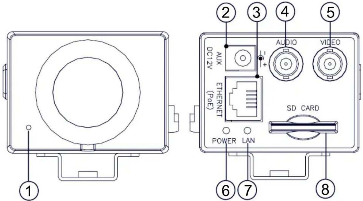
-- Front Panel -- -- Rear Panel --
text_image
1 2 3 4 5 AUDIO VIDEO DC12V AUX ETHERNET (PoE) SD CARD POWER LAN 6 7 81 MICROPHONE: The IP camera has an additional audio function. The device has a microphone built into its front panel which records sound.
2 Plug Inlet: A DC 12V inlet that connects to an external power supply.
3 ETHERNET (PoE): This is a standard RJ-45 connector for 10/100 Mbps Ethernet networks. PoE (Power over Ethernet) function: Provides power to the device via the same cable as used for the network connection.
4 AUDIO OUT Connector: The connector provides the unit's audio signal to a speaker.
5 VIDEO OUT Connector: The connector provides the unit's composite video signals to a monitor.
6 POWER indicator: Indicates the power status of the unit. The green light indicates the unit is activating. The red light indicates the power is on and the SD card cannot be removed.
7 LAN indicator: Indicates the LAN status of the unit. The green light indicates the 100 Mbps Ethernet network is activating. The red light signals the LAN is data linking.
8 SD CARD slot: This is used for system software updating and archiving / accessing critical images.
2.2 Flank Panel
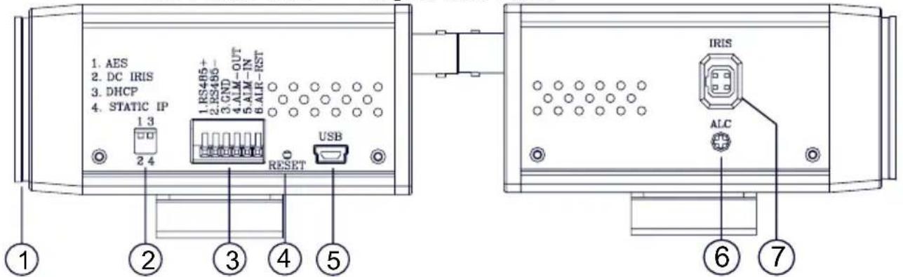
-- Left Flank Panel -- -- Right Flank Panel --
text_image
1. AES 2. DC IRIS 3. DHCP 4. STATIC IP 1 3 2 4 1.RS405+ 2.RS406- 3.CND 4.ALM - OUT 5.ALM - IN 6.ALR - REST RESET USB ① ② ③ ④ ⑤ ⑥ ⑦ IRIS ALC- Lens Mount: This IP camera is used with either a C or a CS mount lens.
- DIP Switch:
1 3 2 4 2 4 | 1. AES: Auto electric shutter. |
| 2. DC IRIS: Use an auto iris (DC drive) | |
| 3. DHCP: Turn On / Turn Off to use the DHCP protocol. If the switch points upwards, the device can change the setup of network function (enable/disable) via the network. | |
| 4. STATIC IP: If the switch points down, the device can’t obtain an IP address from the DHCP server. This option is needed to configure the network communication settings. |
-
ALARM I/O: This is a 6-PIN connector including the ALARM IN/OUT, ALARM RESET and GROUND items for connecting with external devices.
-
RS485 pin: D+
- RS485 pin: D-
● GND: Ground Contact. - ALARM IN (INPUT): This is an alarm input which can be programmed in the menu system to Normally Open or Normally Closed. ( 5V 0V(Active) )
- ALARM OUT (OUTPUT): This is an alarm-output trigger. Connect this to external devices such as buzzers or lights. ( 5V 0V(Active) )
-
ALARM RST (RESET): This pin connects to an alarm-clear device for clearing an alarm. ( 5V 0V(Active) )
-
RESET: Recover to factory default.
- 5pin MINI USB Port: The user can use a USB device cable to connect the IP camera to the USB port on the PC.
- ALC VR: Iris control VR.
When an auto iris (DC Drive) lens is used, this VR is used to adjust the iris for different lighting environments. Adjust the VR clock-wise to open the iris and counter-clockwise to close the iris of the camera.
- IRIS: Auto iris connector.
This camera works with a DC drive auto iris lens. Please refer to the pin assignment marked on the camera when connecting the auto iris lens.
2.3 The USB function
By connecting the IP camera with a PC via the USB connector, the IP camera can provide two different functions.
- Insert an SD card: As a card reader.
Insert an SD card into the IP camera, then connect to the PC. You might transfer files between the SD card and the PC. Once you've connected your IP camera to your computer, the Windows system will detect the connection and ask you what you want to do with your SD card.
In another words, if the user connects the IP camera with an SD card and the PC via the USB connector, the IP camera can be used as a normal card reader.
- Remove an SD card: As a configuring tool.
Before using the USB configuration setting page, please remember to remove the SD card or your PC will read the SD card and won't show this window.
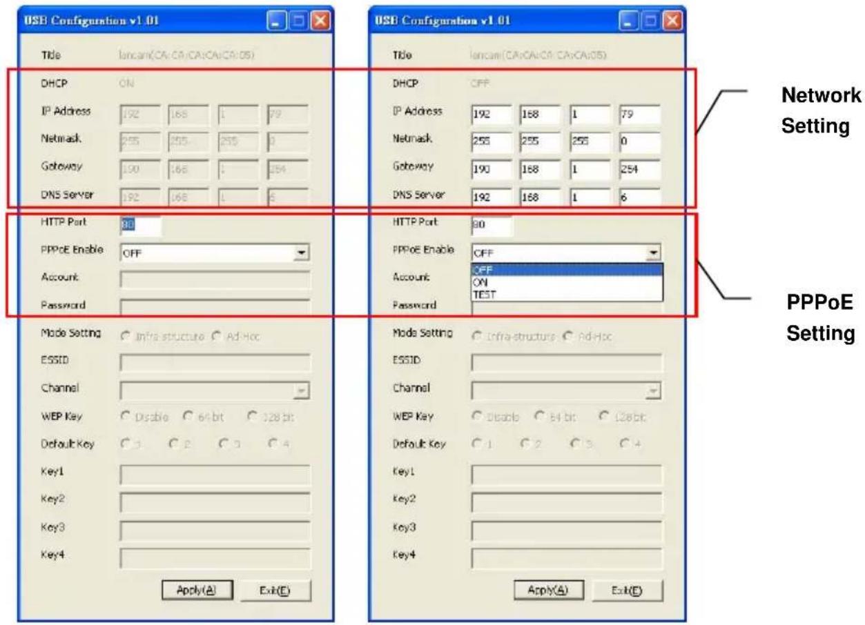
text_image
USB Configuration v1.01 Title lancam(CA:CA:CA:CA:CA:CA:OS) DHCP ON IP Address 192 168 1 79 Netmask 255 255 255 0 Gateway 190 168 1 254 DNS Server 192 168 1 5 USB Configuration v1.01 Title lancam(CA:CA:CA:CA:CA:OS) DHCP OFF IP Address 192 168 1 79 Netmask 255 255 255 0 Gateway 190 168 1 254 DNS Server 192 168 1 6 HTTP Port 30 PPPoE Enable OFF Account Password HTTP Port 30 PPPoE Enable OFF Account OFF ON TEST Password Mode Setting Infra structure Ad Hoc ESSID Channel WEP Key Disable Bit 128 bit Default Key C 2 C 3 C 4 Key1 Key2 Key3 Key4 Apply(A) Exit(E) Mode Setting Infra structure Ad Hoc ESSID: Channel WEP Key Disable Bit 128 bit Default Key C 1 C 2 C 3 C 4 Key1 Key2 Key3 Key4 Apply(A) Exit(E) Network Setting PPPoE SettingDHCP ON DHCP OFF
WARNING: After changing the settings, please click the "Apply" button. All of the options will be effective after removing the USB connector.
2.4 PoE (Power over Ethernet)
These technologies will enable the development of new networked appliances, by providing power as well as data over existing Ethernet cables.
The Summary Comparison of PoE Standards (Table 1) is listed as follows.
| Table 1. Summary Comparison of PoE Standards | ||||||||||||
| STANDARD | SOURCE | LOAD | REMARKS | |||||||||
| Source Voltage | Ethernet RJ-45 connector pin number * | |||||||||||
| 1 | 2 | 3 | 4 | 5 | 6 | 7 | Load8Voltage | DC Load Connector | ||||
| IEEE 802.3af using data pairs | 48 V DC, protected | RX, DC+ | RX, DC+ | TX, DC- | spare | spare | TX, DC- | spare | spare | (embedded) | Industry Standard for embedded PoE | |
| IEEE 802.3af using spare pairs | 48 V DC, protected | RX | RX | TX | DC+ | DC+ | TX | DC- | DC- | (embedded) | Industry Standard for embedded PoE | |
The compatible PoE Hubs (Table 2), which can be used with the unit, are shown in the tables below.
| Table 2. Compatible PoE HUB | |||
| Manufacturer | Model | Port | Note |
| PLANET | FSP-804P | 4 | Port PoE HUB |
| POE-151 | 1 Port PoE HUB | ||
| D-Link | DWL-P200 | 1 Port PoE HUB | |
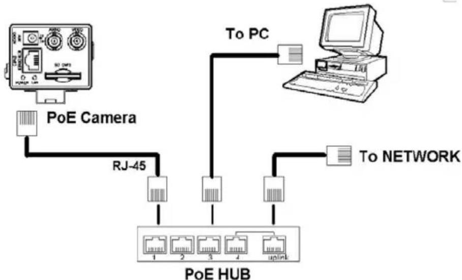
Connect to a PoE HUB
The Standard RJ-45 PIN configuration for connecting with a PoE HUB is shown below.
flowchart
graph TD
    A["PoE Camera"] -->|RJ-45| B["PoE HUB"]
    C["To PC"] -->|To NETWORK| B
    D["Computer"] -->|To Network| B
    B --> E["1 2 3 4 uplink"]
3. INSTALLATION
Please follow the instructions and the diagram below to set up the system.
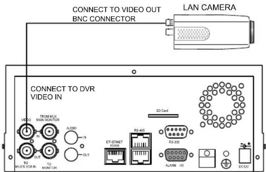
NOTE: The ipxcam is linked by its Video Out connection via a BNC connector to a monitor's Video In connection. If this connection is there, you can see some information on the monitor screen, such as the IP camera factory default Static IP address(192.168.1.168). But the IP camera Static IP address can only appear if there is a connection between the IP camera and another device. If there is no such connection, the IP camera factory default Static IP address will not appear on the monitor screen.
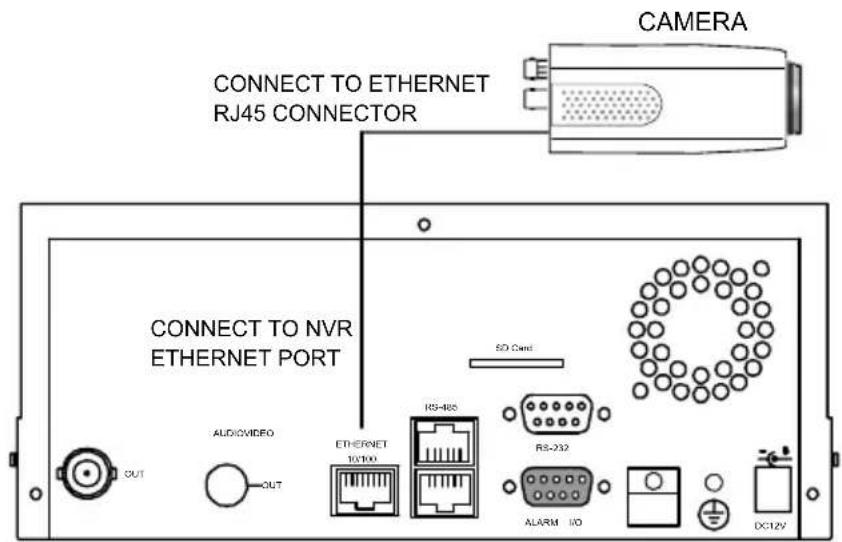
3.1 CONNECTING WITH AN NVR
Use a straight LAN cable to connect directly to an NVR.
text_image
CONNECT TO ETHERNET RJ45 CONNECTOR CAMERA CONNECT TO NVR ETHERNET PORT AUDIOVIDEO OUT ETHERNET 10/100 RS-485 RS-232 ALARM I/O DC12V3.2 CONNECTING WITH A DVR
text_image
CONNECT TO VIDEO OUT BNC CONNECTOR LAN CAMERA CONNECT TO DVR VIDEO IN VIDEO FROM MUX MAIN MONITOR IN AUDIO IN OUT OUT TO MUX'S VCR IN TO MONITOR SO Card ETHERNET 10/100 RS 485 RS 232 ALARM I/O DC12V3.3 CONNECTING WITH A MULTIPLEXER
flowchart
graph TD
    A["Camera Video OUT BNC CONNECTOR"] --> B["CAMERA 1"]
    A --> C["CAMERA 2"]
    A --> D["CAMERA 16"]
3.4 UPDATING SYSTEM SOFTWARE
If the system software of the IP camera needs to be upgraded, please take the following steps to safely process it.
Important: Before carrying out the following procedures, please ensure the SD card is working and the file of the system firmware is intact
- Format an SD card using the FAT16 format if it is unformatted; there are no limitations to an SD card's capacity.
- Create a directory named IPXCAM in the SD card if it does not exist.
- Copy the file of UPDATE.BIN to the IPXCAM-directory.
- If the IP camera is running, please power it off first.
- Insert the SD CARD into the IP camera.
- Remove the Ethernet cable from the RJ-45 port and then power on the IP camera.
- In 5 to 10 seconds, a message reading "UPDATE PROCESSING" will show up on the screen on a blue background; if not, please check out steps 1 to 6 carefully or else inform your technical support while ignoring the following steps.
-
DO NOT power off the IP camera while this update process is running until the message "UPDATE OK RESET PLEASE" appears on the screen; it might take 15 to 30 seconds to appear.
-
If the message "UPDATE NG RESET PLEASE" appears rather than "UPDATE OK RESET PLEASE", please write down the error messages shown on the screen and inform your technical support, while ignoring the following steps.
- Power off the IP camera when this update process is finished, then remove the SD card from the IP camera.
- Reconnect the Ethernet cable to the RJ-45 port if necessary.
- Power ON the IP camera and it will work normally if the entire update procedure goes correctly.
- Verify the version of the system software.
WARNING:
- Don't use FAT32 or NTFS or other file formats in step 1.
- Steps 1 to 3 have to be done on a PC.
- Make sure the file of UPDATE.BIN is a correct one in step 3, or the IP camera will not work normally after being updated.
- If the power of the IP camera is suddenly lost in step 8, please remove the SD card first and turn on the IP camera next to test its operation. If the IP camera remains working normally, please go back to step 4; otherwise, please inform your technical support.
- In step 10, if the SD card is not removed and the IP camera does not get online as well, the updating process must be repeated again after rebooting the IP camera.
- Make sure that the SD card is inserted in a correct position in step 5, or the IP camera will suffer permanent physical damage.
- If the message "CSUM ERROR" appears in step 8, it implies a problem in the file of UPDATE.BIN.
- Don't interrupt the process while the unit is updating itself; proceed with an SD card not including any system software of the unit, or else the unit will crash.
3.5 IP camera SD card Troubleshooting
- Check if the SD card position is correct or not. Please refer to the manual for the related information.
-
After powering the IP camera on, correctly insert the SD card, and a little icon of "SD" will show up in the upper-right corner of the monitor screen. If not, it means the device detection has failed. Please contact your technical support and ignore the following steps.
-
If no cross sign appears beside the "SD" icon, please go on to the next step. If a cross sign appears, please check the following:
a. Is it really an SD "Memory" Card?
b. Is this SD card formatted in the FAT16 format?
c. Connect the SD card with a PC and test to see whether the PC can read the data or not.
d. Does this SD card still have the capacity for storing data?
e. Is the SD card set to write?
If all the answers are "yes" but the cross sign still persists, please contact your technical support and ignore the following steps.
-
Please make sure the function of "SD CARD ENABLE" is activated in the ALARM and SCHEDULE pages if no cross sign appears beside the "SD" icon on the screen.
-
After recording, read the data on the web page of "sdget.htm". If the data cannot be read through the network, please read it instead in a PC, check the data stored in the "IPXCAM" directory and contact your technical support regardless of whether there is data or not.
WARNING :
-
Performing this troubleshooting process may need a monitor, a PC, a card reader and some cables.
-
If the SD card is removed while storing or accessing data, the data will be lost.
-
If there is a cross sign beside the "SD" icon, it means the SD card has been inserted into the IP camera but cannot perform its writing function. Possible reasons are:
a. It is not an SD memory card.
b. The SD card is unformatted or formatted in a non-FAT16 or non-FAT12 format.
c. The file system is damaged.
d. The capacity of the SD card is full.
e. The SD card is set to be read only.
- Turn off the power before inserting the SD card. Otherwise the unit may shut down.
4. Network Configuration
4.1 Cable Connections
Please follow the instructions below to connect your IP camera to a computer or a network and to choose a proper RJ-45 cable configuration for connections.
Physical specifications of the RJ-45 cable for Ethernet
| Wire Type Cat. 5 |
| Connector Type RJ-45 |
| Max. Cable Length 100 m |
| Hub Wiring Configuration Straight Through |
| PC Wiring Configuration Straight |
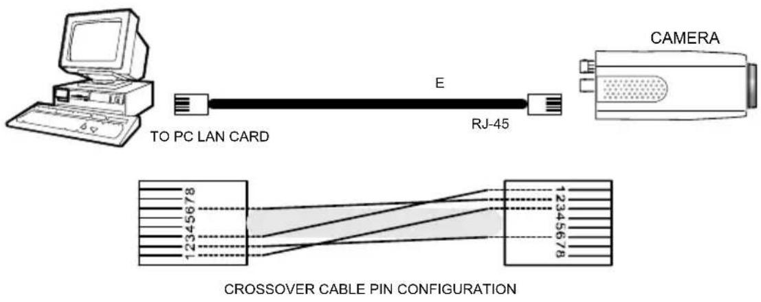
4.1.1 Connect to a computer
Use a straight LAN cable to connect directly to a computer.
text_image
TO PC LAN CARD E RJ-45 CAMERA CROSSOVER CABLE PIN CONFIGURATION4.1.2 Connect to a LAN Hub (INTRANET)
The RJ-45 PIN configuration for connecting with a LAN Hub is shown below.
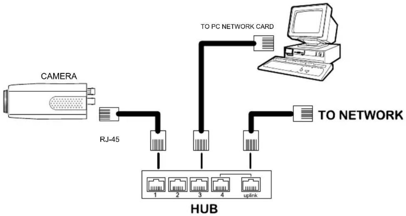
flowchart
graph TD
    A["CAMERA"] --> B["RJ-45"]
    B --> C["TO PC NETWORK CARD"]
    C --> D["TO NETWORK"]
    D --> E["HUB"]
    E --> F["1"]
    E --> G["2"]
    E --> H["3"]
    E --> I["4"]
    E --> J["uplink"]
4.2 Configure Your IP camera Network Settings
Upon connecting with the network hardware, you need to activate the network function and configure the proper network settings of the IP camera.
4.2.1 Enable DHCP Function
This function can only work if the LAN, which the unit is connected to, has a DHCP server. If the DHCP server is working, please move the dip switch points up to 3 on the flank panel; now the IP camera will obtain an IP address automatically from the DHCP server. In that case, please skip section 4.2.2 (Set IP address) and follow section 4.3 (TCP/IP Communication Software).
4.2.2 Set IP Address
You need to set an IP address for the unit if the LAN unit isn't connected to a DHCP server.
Otherwise, please follow the instructions given below:
Set the IP, MASK and GATEWAY. The following is a sample setting.
IP: 192.168.1.X
MASK: 255.255.255.0
GATEWAY: 0.0.0.0
NOTE: When only one unit of the IP camera is connected to a computer or LAN, you can freely assign an IP address for the IP camera. For example, there is a range of IP camera IP addresses from 192.168.1.1 to 192.168.1.255. You can pick one for use from the range of the IP. It's not necessary to set MASK and GATEWAY; leave the settings as default.
When an IP camera is connected to a WAN, you must acquire a unique, permanent IP address and correctly configure the MASK and GATEWAY settings according to your network architecture. If you have any questions regarding those settings, please consult a qualified MIS professional or your ISP.
NOTE: When connecting to a network, each connected IP camera must be assigned a unique IP, which must be in the same class type as your network address. IP addresses are written as four sets of numbers separated by periods; for example, 192.168.1.1 Therefore, if the connected network is identified as Class C, for example, the first three sets of numbers of the IP camera IP address must be the same as the network address. If the connected network is identified as Class B, the first two sets of numbers of the IP camera IP address must be the same as the network address. If you have any questions regarding these settings, please consult a qualified MIS professional or your ISP.
4.3 TCP/IP Communication Software
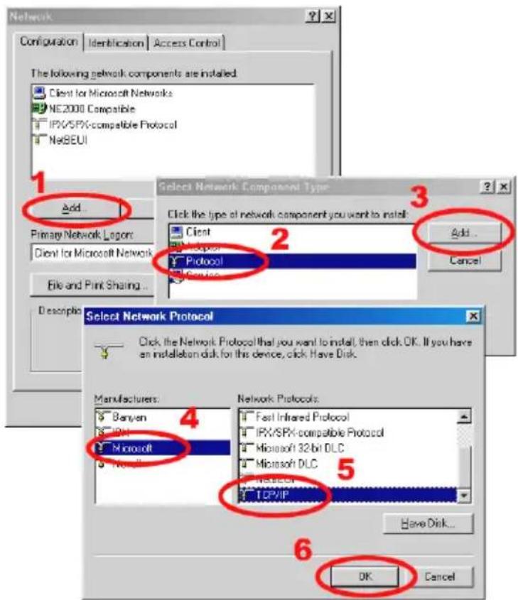
Follow the procedure below to install the TCP/IP communication program in your computer.
Click the Start menu from your computer, and point to the Settings/Control Panel.
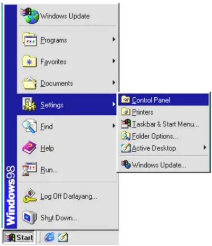
text_image
Windows Update Programs Favorites Documents Settings Find Help Run... Log Off Darlayang... Shut Down... Control Panel Printers Taskbar & Start Menu... Folder Options... Active Desktop Windows Update... StartDouble click the Network icon to enter the windows.
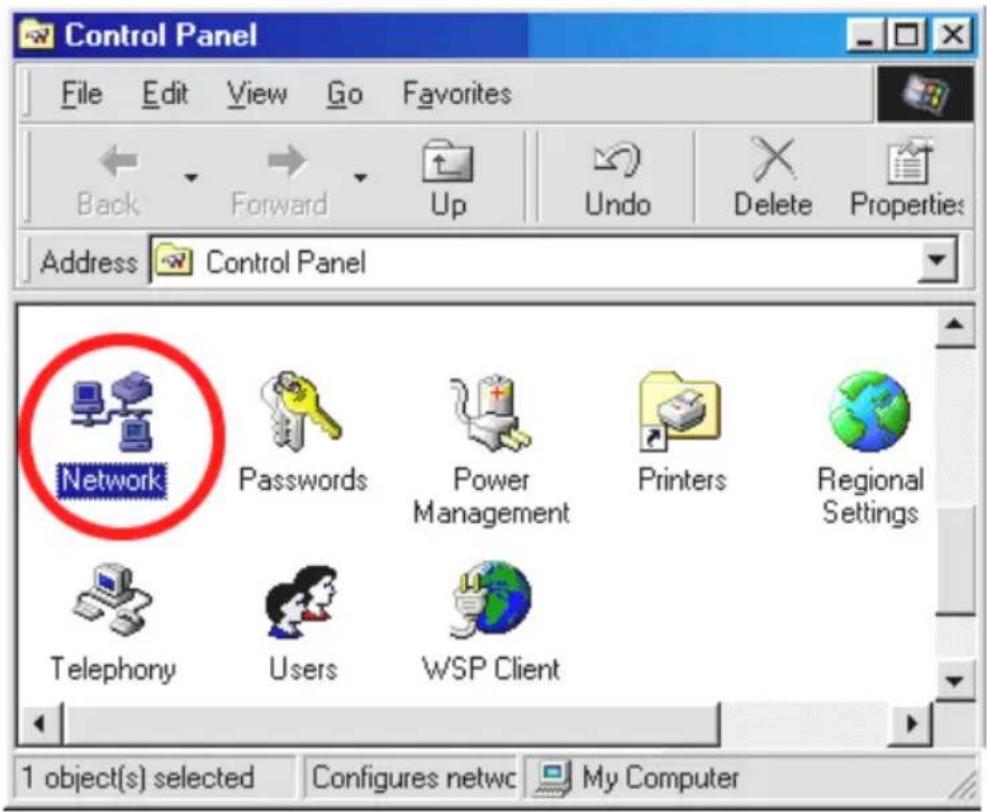
text_image
Control Panel File Edit View Go Favorites Back Forward Up Undo Delete Properties Address Control Panel Network Passwords Power Management Printers Regional Settings Telephony Users WSP Client 1 object(s) selected Configures netwc My ComputerClick the Configuration tag, and check if the TCP/IP is included among the network components list. If the TCP/IP is included, please process section 4.5. If it is not included, please follow section 4.4 to install the TCP/IP.
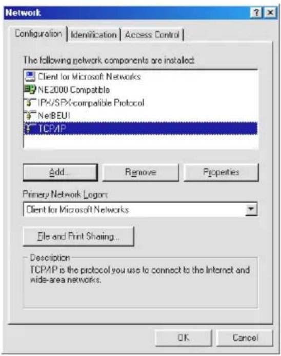
text_image
Network Configuration | Identification | Access Control | The following network components are installed: Client for Microsoft Networks NE2000 Compatible IPX/SPX-compatible Protocol NetBEUI TCP/IP Add... Remove Properties Primary Network Logon: Client for Microsoft Networks File and Print Sharing... Description TCP/IP is the protocol you use to connect to the Internet and wide-area networks. OK Cancel4.4 TCP/IP Installation
text_image
Network Configuration | Identification | Access Control | The following network components are installed: Client for Microsoft Networks NE2000 Compatible IPW/SPX-compatible Protocol NetBEUI 1 Add... Primary Network Logos: Client for Microsoft Network File and Print Sharing... Description Select Network Component Type Click the type of network component you want to install: Client Protocol Protocol Edit... Add... Cancel Select Network Protocol Click the Network Protocol that you want to install, then click OK. If you have an installation disk for this device, click Have Disk. Manufacturers: Banyen IPW Microsoft Network Protocols: Fast Infrared Protocol IPW/SPX-compatible Protocol Microsoft 32-bit DLC Microsoft DLC InSICUC TCP/IP 5 Have Disk... OK CancelDuring the installation, you will be requested to insert the Windows CD-ROM. After installation, the PC may be restarted.
4.5 TCP/IP configuration setting
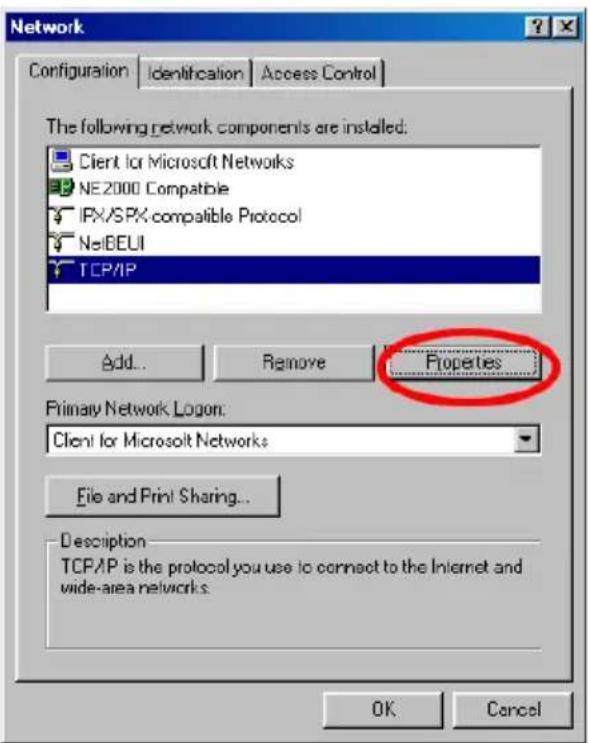
Click Start → Settings → Control Panel → Network.
Select TCP/IP, and then click Properties.
Before processing the IP camera installation in a WAN, please make sure the Internet connection works properly. If not, please contact your ISP provider.
text_image
Network Configuration Identification Access Control The following network components are installed: Client for Microsoft Networks NE2000 Compatible IPX/SPX-compatible Protocol NetBEUI TCP/IP Add... Remove Properties Primary Network Logon: Client for Microsoft Networks File and Print Sharing... Description TCP/IP is the protocol you use to connect to the Internet and wide-area networks. OK Cancel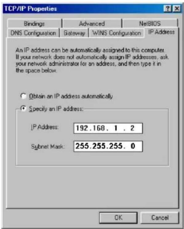
text_image
TCP/IP Properties Bindings Advanced NetsBIOS DNS Configuration Gateway WINS Configuration IP Address An IP address can be automatically assigned to this computer. If your network does not automatically assign IP addresses, ask your network administrator for an address, and then type it in the space below. Obtain an IP address automatically Specify an IP address: IP Address: 192.168.1.2 Subnet Mask: 255.255.255.0 OK CancelIf you are using a DHCP server, please select Obtain an IP address automatically. Any assigned IP address for the connected IP cameras must be in the same class type as the server. If there is no DHCP server, please select specify an IP address and type in the IP address of your PC. This IP address must be different from other network IP devices but in the same class type.
NOTE: The IP address of an IP camera in a network must be unique to itself as opposed to those of the other chosen PCs, but in the same class type.
4.6 Connection Testing
With the previous settings, follow the instructions below to ensure whether you have established the connection successfully.
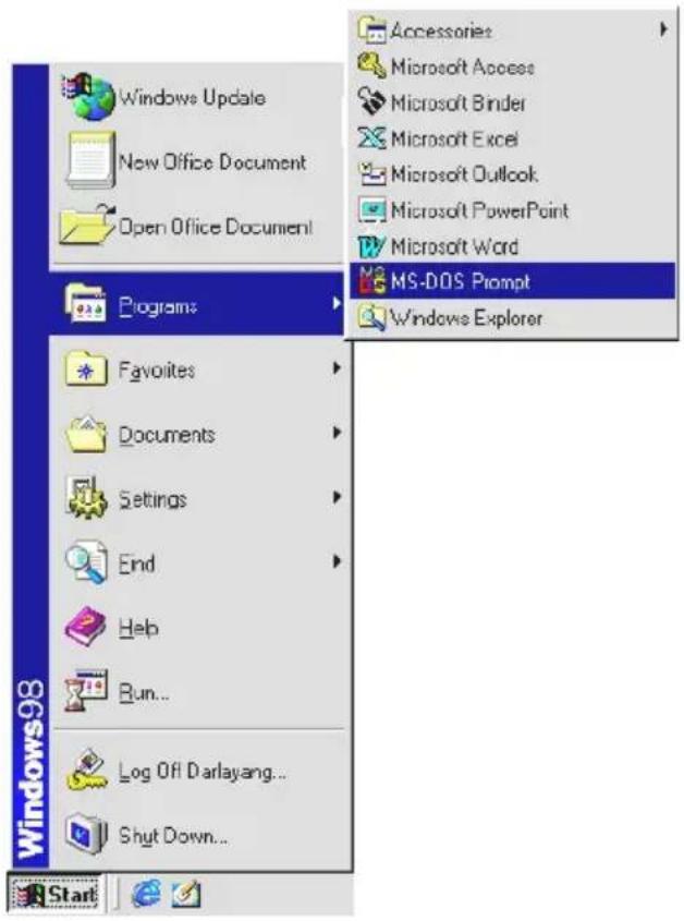
Click Start → Programs → MS-DOS Prompt
text_image
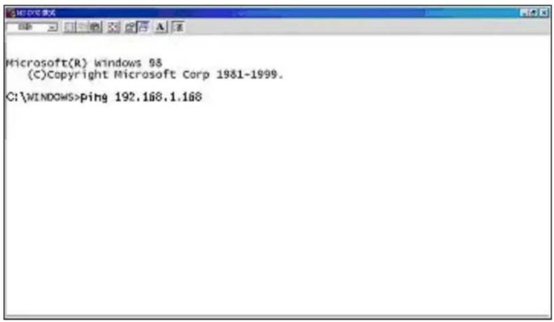
Windows98 Start Programs Favorites Documents Settings End Help Run... Log Off Darlayang... Shut Down... Accessories Microsoft Access Microsoft Binder Microsoft Excel Microsoft Outlook Microsoft PowerPoint Microsoft Word MS-DOS Prompt Windows ExplorerType in ping 192.168.1.168, then enter. (See the sample screen below).
** This IP is the IP camera IP address that is assigned for the connected IP camera in step2.
text_image
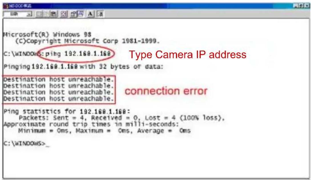
Microsoft(R) Windows 98 (C)Copyright Microsoft Corp 1981-1999. C:\WINDOWS>ping 192.168.1.168If you receive a response as in the sample screen below, the connection hasn't been successfully established. Please re-check all the hardware and software installations by repeating steps 1 to 5. If you still can't establish the connection after rechecking, please contact your dealer.
text_image
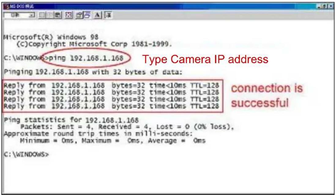
Microsoft(R) Windows 9$ (C)Copyright Microsoft Corp 1981-1999. C:\WINDOWS:ping 192.160.1.160 Pinging 192.160.1.160 with 32 bytes of data: Destination host unreachable. Destination host unreachable. Destination host unreachable. Destination host unreachable. Ping statistics for 192.160.1.160: Packets: Sent = 4, Received = 0, Lost = 4 (100% loss), Approximate round trip times in milli-seconds: Minimum = Oms, Maximum = Oms, Average = Oms C:\WINDOWS>If you receive a response as in the sample screen below, you have successfully made the connection.
text_image
Microsoft(R) windows 98 (C)Copyright Microsoft Corp 1981-1999. C:\WINDOWS>ping 192.168.1.168 Pinging 192.168.1.168 with 32 bytes of data: Reply from 192.168.1.168 bytes=32 time<10ms TTL=128 Reply from 192.168.1.168 bytes=32 time<10ms TTL=128 Reply from 192.168.1.168 bytes=32 time<10ms TTL=128 Reply from 192.168.1.168 bytes=32 time<10ms TTL=128 Ping statistics for 192.168.1.168 Packets: Sent = 4, Received = 4, Lost = 0 (0% loss), Approximate round trip times in milli-seconds: Minimum = Oms, Maximum = Oms, Average = Oms C:\WINDOWS>5. Operating Instructions for Image Software and Network
Two choices of software are available for linking with the IP camera: (1) the Microsoft Internet Explorer; and (2) the IP camera VIEWER, a network browser in a PC which provides the functions of monitoring remote zones or watching recorded data through the TCP/IP protocol. The details are listed as follows.
RJ-45 PIN configuration for Ethernet
| PIN NO. PIN | Assignment |
| 1. TX + | |
| 2. TX - | |
| 3. RX + | |
| 4. Not Connected | |
| 5. Not Connected | |
| 6. RX - | |
| 7. Not Connected | |
| 8. Not Connected | |
RJ-45 socket

text_image
1 2 3 4 5 6 7 8Physical specification for Ethernet
| Wire type Cat. 5 | |
| Connector type RJ-45 | |
| Max. cable length 100 m | |
| Hub wiring configuration Straight Through or Cross Over | |
| PC wiring configuration Straight Through or Cross Over | |
5.1 Microsoft Internet Explorer
5.1.1 Connecting the IP camera
- Start up the Microsoft Internet Explorer, and then follow the steps below to connect the IP camera.
- Click the URL block at the top of the window.
- Enter the URL address of the IP camera into the URL block and press the "Enter" button to enter the home page.
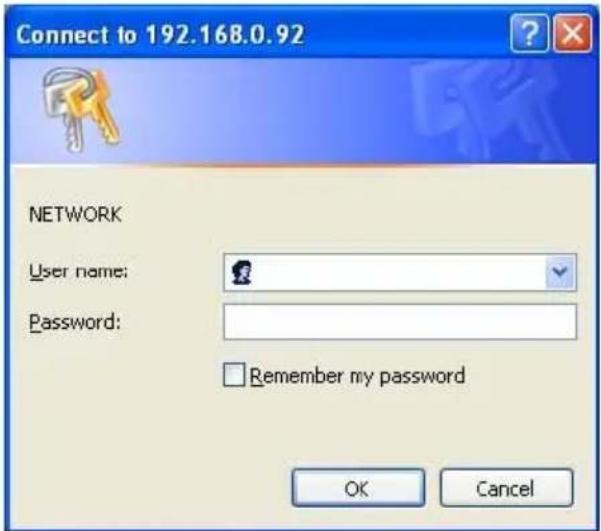
- Scroll to the bottom of the page, with its five icons, "Image", "Network", "System", "Application" and "SD card". Whichever you click, the page headlined "Enter Network Password" will appear.
- Type in the "User Name" and "Password" in the appropriate spaces.
- Click the "OK" button to set your entries, and automatically exit the page.
NOTE: The default "User Name" and "Password" are root and Admin respectively.
NOTE: The page headlined "Enter Network Password" is shown below. Please enter the user name and password of the IP camera when you see it. If either the user name or the password is incorrect, please check the input data and rectify it if necessary.
NOTE: Once authorized successfully, it will not appear again until you close the window and reconnect it.
NOTE: The initial sequence of proceeding is to type in your IP address and click the "Enter" button to access the home page. If and when you revise or change data in the "SYSTEM USERS" page, the sequence will alter to initially show the "Enter Network Password" page.
text_image
Connect to 192.168.0.92 NETWORK User name: Password: Remember my password OK CancelBrowsing images from the IP camera
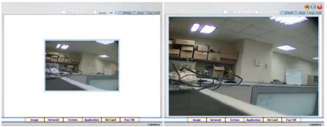
The images from the IP camera will be displayed on the home page while going online with the IP camera. Some buttons of the home page are provided for further setting. In MJPEG mode or in MPEG4 mode, there are different display formats of its home page.
text_image
2016-013/04:22:06:58 Room Box House | Italy | Buy Chat Image Network System Application SD Card Pan/Tilt camera Image Network System Application SD Card Pan/Till camera- Click the Image button to enter the image-setting page.
- Click the Network button to enter the network-setting page.
- Click the System button to enter the system-setting page.
- Click the Application button to enter the application-setting page.
- Click the SD card button to open the SD card- FILELIST of the MEMORY CARD window, if the SD card is inserted.
- Click the Pan/Tilt button to change the Pan/Tilt/Zoom settings.
- Click the 11:10/2005 14:31:37 button to change the time/date display mode.
- Click the 📋 button to switch high/low speed network.
- Click the 📷 button to play the live audio. Click once again to deactivate.
- Click the 🎨 button to archive AVI videos into your PC. Click once again to deactivate. In the recording mode, there will appear a red twinkling icon ⚙ in the upper-right hand corner of the image. The AVI file will be saved in the path of c:.
- Digital zoom function: Click the left mouse button on the video display area, and it will show the zoom-in images. Double click the left mouse button to see the maximum size. Click the right mouse button on the video display area, and it will show the zoom-out images. Double click the right mouse button to come back to the normal size.
5.1.2 Change Image Setting
Please follow the steps below to change the image setting through the network if necessary.
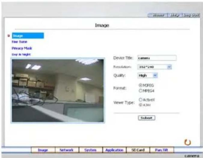
- Click the Image button on the home page to enter the image-setting page.
text_image
Image File Turn Privacy Mask Day & Night Device Title: Camera Resolution: 352*240 Quality: High Format: MPBG MPBG4 Viewer Type: ActiveX A1X1 Subset Image Network System Application SD Card Pan Tilt camera
text_image
Image Image Free Tune Privacy Mask Day is night Device Title: Camera Resolution: Full01 Quality: High 81.24 kbps Frame Rate: 24FPS Format: MPEG MPEG4 Submit Image Network System Application SD Card Pass Tilt CameraImage setting page of MJPEG mode Image setting page of MPEG4 mode
- Adjust the image setting including "Device Title", "Resolution", "Quality", "Frame rate" (MPEG4 mode only), "Format", and "Viewer Type" (MJPEG mode only) if necessary.
- Click the Submit button to submit the new image setting.
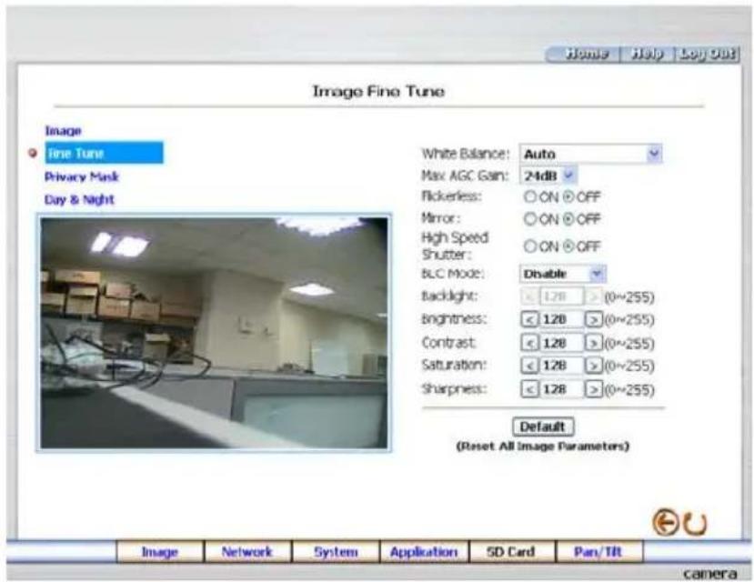
- Click the Fine Tune button to enter the Image Fine Tune page to set the details of the device including: "Brightness", "Saturation" and "Sense Up". Click the Default button to reset all the settings.
NOTE: The revised image will appear immediately after any change in made.
text_image
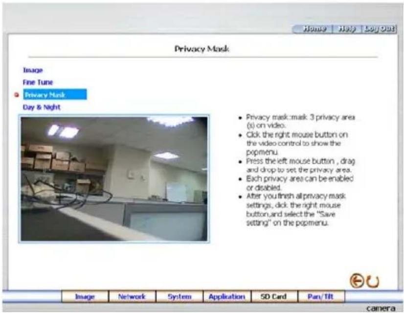
Image Fine Tune Image Fine Tune Privacy Mask Day & Night White Balance: Auto Max AGC Gain: 24dB Pickerless: ON OFF Mirror: ON OFF High Speed Shutter: ON OFF BLC Mode: Disable Backlight: 1.78 (0~255) Brightness: 1.28 (0~255) Contrast: 1.28 (0~255) Saturation: 1.28 (0~255) Sharpness: 1.28 (0~255) Default (Reset All Image Parameters) Image Network System Application SD Card Pan/TLR camera- Click the Privacy Mask button to enter the Privacy Mask page.
text_image
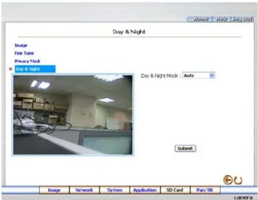
Home | Help | Buyout Privacy Mask Image Fine Tune • Privacy Mask Day & Night • Privacy mask: mask 3 privacy area (s) on video. • Click the right mouse button on the video control to show the popmenu. • Press the left mouse button , drag and drop to set the privacy area. • Each privacy area can be enabled or disabled. • After you finish all privacy mask settings, click the right mouse button, and select the "Save setting" on the popmenu.- Click the Day & Night button to enter the Privacy Mask page. Click the drop-down list to choose the Day & Night mode of "Auto", "Day mode", "Night mode" and "Schedule".
text_image
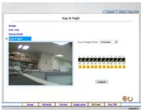
Home | Help | Log Out Day & Night Image Fine Tune Privacy Mask Day & Night Day & Night Mode : Auto Submit Image Network System Application SD Card Pan/ Tilt cameraNote: In the “Schedule” mode, you can click the icon to set the Day 🙏 or Night 📄 mode of each hour. “0” means “00:00\~00:59”, “1” means “01:00\~01:59”, and so on.
text_image
Day & Night Image New Time Primary Mask Day & Night Day & Night Info: Calendar 12/13/04 15:16 17:18 19:20 21:22 23:24 12/13/04 15:16 17:18 19:20 21:22 23:24 System Image Network Options Applications UI Card Fee YR camera- Click the Home button to return to the home page while the new image setting acts on the images to effect the desired changes instantly. (If the setting has not been changed by the above steps, any (re)entry onto the home page will find images in their earlier or original setting.)
Exchange the image format
- Tick on one of the formats then press the Submit button.
- The IP camera will restart automatically after several seconds.
Description of function keys:
MPEG4 mode:
Device Title: Type in the camera title in the given space.
Resolution: Scroll to choose the image resolution from "VGA" or "QVGA".
Quality: Scroll to choose the image quality out of a spectrum of qualities ranging from "highest", "high", "medium", and "low" to "lowest". In MPEG4 mode, you can also set the quality by typing in the value. The custom quality value must be in the range between 64 Kbps to 8192 Kbps.
Frame rate: Click the drop-down list to choose the frame rates of "15FPS", "24FPS" or "25FPS".
Format: Click to choose the "MJPEG" or the "MPEG4" mode.
Fine Tune mode
Brightness: Enter your desired quality of image brightness from a spectrum of 0 to 255.
Saturation: Type in the saturation level in the blank (0 to 255).
MJPEG mode:
Viewer type: Click to choose the viewer type of the "ActiveX" or "AJAX" mode.
Submit: Click to submit the new image setting to the IP camera.
Default: Click this button to install the default settings in all the entries for image parameters on this page.
5.1.3 Change the Network Setting
Please follow the steps below to change the network setting through the network if necessary.
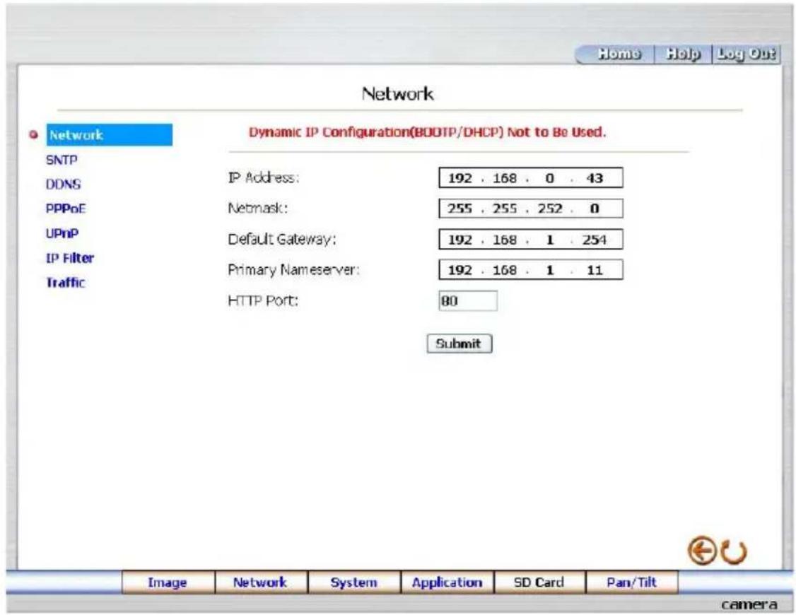
- Set the network options and IP address.
- Click the Network button in the home page to enter the Network page.
text_image
Network Dynamic IP Configuration(BODTP/DHCP) Not to Be Used. SNTP DDNS PPPoE UPnP IP Filter Traffic IP Address: 192 . 168 . 0 . 43 Netmask: 255 . 255 . 252 . 0 Default Gateway: 192 . 168 . 1 . 254 Primary Nameserver: 192 . 168 . 1 . 11 HTTP Port: 80 Submit Image Network System Application SD Card Pan/Tilt camera- The accessible networks here are the "SNTP", "DDNS", "PPPoE", "UPnP" and the "Traffic".
- Fill in the "IP Address", "Netmask", "Default gateway", "Primary nameserver", and "HTTP Port" if necessary.
- Click the Submit button to submit the new network setting.
- Click the Home button to return to the home page.
Description of function keys:
IP Address: Enter the 4-byte IP Address in the appropriate blank space (the value in each box may be anywhere between 0 and 255). Every IP camera has to own an IP address to be identified on the network.
Netmask: Fill in the 4-byte Subnet Mask in the required blank spaces (usually any numbers between 0 and 255). It is used to identify the subnet where the IP camera is sited.
Default Gateway: Type in the 4-byte Gateway in the relevant blank spaces (each unit value must be between 0 and 255).
Primary Nameserver: Enter the 4-byte DNS Server Address in the blank spaces provided (each value unit must be between 0 and 255). The DNS Server is in charge of translating the Domain Name into the IP Address.
HTTP Port: Indicates the specific HTTP Port Number. The default is 80.
Submit: Click to submit the new network setting to the IP camera.
Please follow the steps below to change the SNTP setting through the network if necessary.
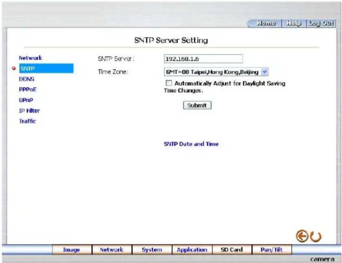
- Click the SNTP button at upper left above to enter the "SNTP Server Setting" page.
text_image
SNTP Server Setting Network SNTP Server: 192.168.1.6 SNTP DDNS Time Zone: GMT+08 Taipei,Hong Kong,Beijing PPPoE UPnP IP Filter Traffic Automatically Adjust for Daylight Saving Time Changes. Submit SNTP Date and Time Image Network System Application SD Card Pan/Tilt camera- Enter the IP Address of the SNTP server, and choose one of the time zones as and when necessary.
- Click "Automatically Adjust for Daylight Saving Time Changes" to checkmark the attached box and activate the function.
- Click the Submit button to submit the new SNTP setting.
- Click the Home button to return to the home page.
Description of function keys:
SNTP Server: Enter the SNTP server DOMAIN NAME in the blank space provided.
Time Zone: As we know, the globe is divided into various time zones. The user must enter his/her time zone. If this is not done, the time given by the unit may be incorrect.
Submit: Click to submit the new SNTP setting to the IP camera.
● Change the Network Setting — DDNS.
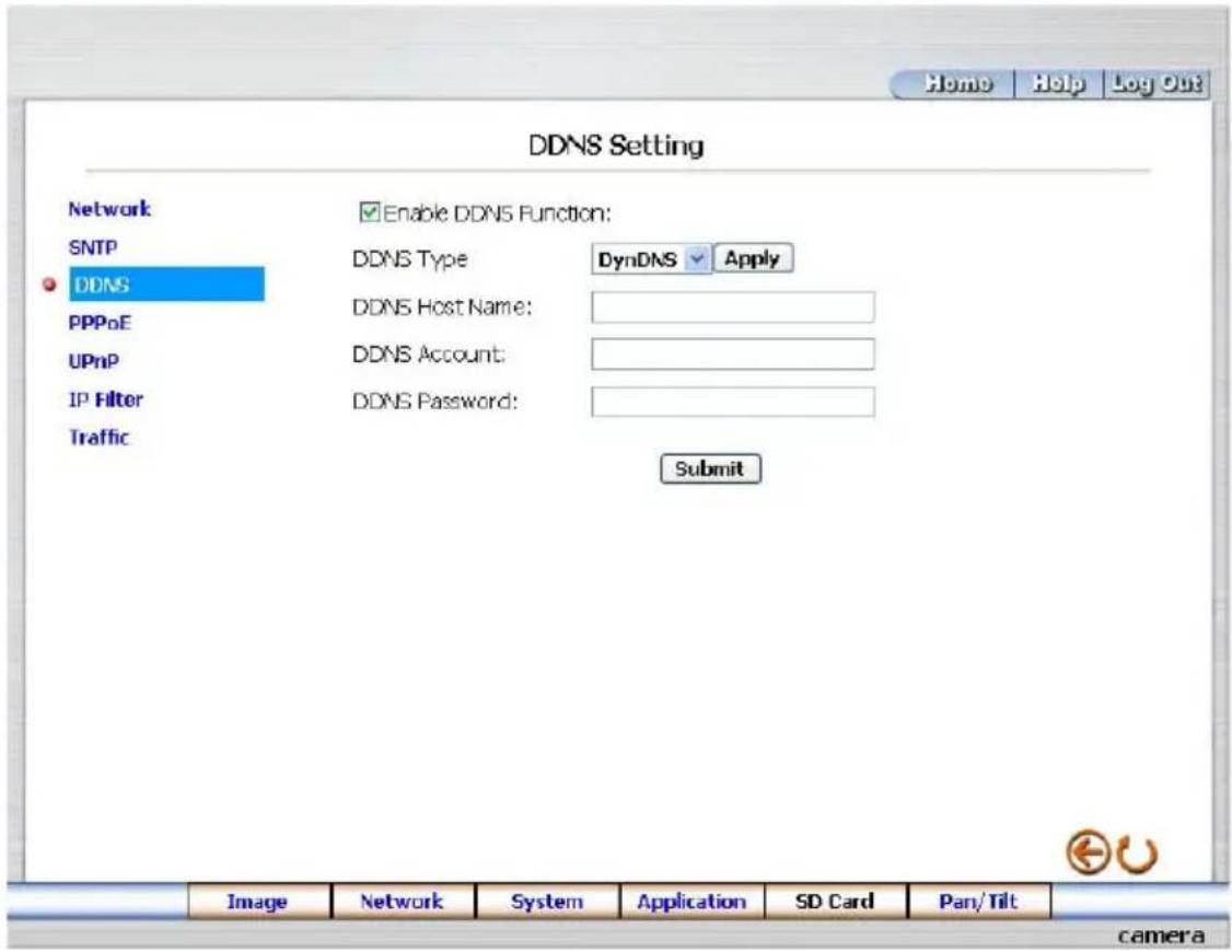
The "Network" page has, on its upper left, the "DDNS" icon. Please follow the steps below to change the DDNS setting through the network if necessary.
- Click the DDNS button at upper left above to enter the "DDNS Setting" page.
text_image
DDNS Setting Network SNTP DDNS PPPoE UPnP IP Filter Traffic Enable DDNS Function: DDNS Type DynDNS Apply DDNS Host Name: DDNS Account: DDNS Password: Submit Image Network System Application SD Card Pan/Tilt camera- Click "Enable DDNS Function" to checkmark the attached box and activate the function.
- Click "DDNS Type" to open the list of two DDNS modes to choose from: "DynDNS" and "hn". Click the "Apply" button and connect their website automatically and visit it. Type in your dynamic IP Address and Email Address. If they are accepted by the website, you will get an Email containing your DDNS Account and DDNS Password in your Email box.
- Type in the "DDNS Host Name", the "DDNS Account" and the "DDNS Password".
- Click the Submit button to submit the new setting.
- Click the Home button to return to the home page.
NOTE: Please refer to section 5.1.8 (PPPoE & DDNS) for more details.
Description of function keys:
Enable DDNS Function: Checkmark to activate the function.
DDNS Type: Click to open the list of two DDNS modes to choose from: "DynDNS" and "hn". Click the "Apply" button and connect this website automatically and enter it. Type in your dynamic IP Address and Email Address. If they are accepted by the website, you will get an Email containing your DDNS Account and DDNS Password in your Email box.
DDNS Host Name: Type in your host name in the attached space.
DDNS Account: Enter it in the given space.
DDNS Password: Enter it in the required space.
Submit: Click to set.
● Change the Network Setting — PPPoE.
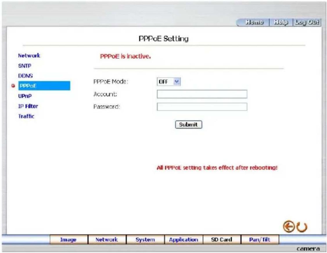
The "Network" page has, on its upper left, the "PPPoE" icon. Please follow the steps below to change the PPPoE setting through the network if necessary.
- Click the PPPoE button at upper left above to enter the "PPPoE Setting" page.
text_image
Home Help Log Out PPPoE Setting Network SNTP DDNS PPPoE UPnP IP Filter Traffic PPPoE is inactive. PPPoE Mode: OFF Account: Password: Submit All PPPoE setting takes effect after rebooting! Image Network System Application SD Card Pan/Tilt camera- Please read the "PPPoE Troubleshooting" document first, then press "Close" button.
- Click the "PPPoE mode" to activate the function.
- Type in the PPPoE "Account" and the PPPoE "Password".
- Click the Submit button to submit the new setting.
- Click the Home button to return to the home page.
NOTE: Please refer to section 5.1.8 (PPPoE & DDNS) for more details.
Description of function keys:
PPPoE mode: Click your choices to enable the PPPoE function.
Account: Enter it in the given space.
Password: Enter it in the required space.
Submit: Click to set.
● Change the Network Setting —UPnP.
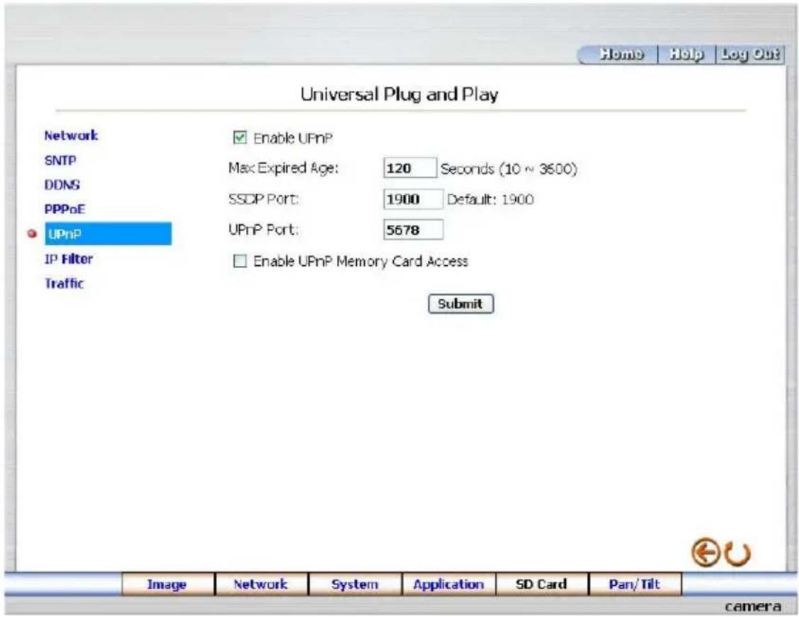
The "Network" page has, on its upper left, the "UPnP" icon. Please follow the steps below to change the UPnP setting through the network if necessary.
- Click the UPnP button at upper left above to enter the "Universal Plug and Play" page.
text_image
Home Help Log Out Universal Plug and Play Network SNTP DDNS PPPoE UPnP IP Filter Traffic Enable UPnP Max Expired Age: 120 Seconds (10 ~ 3600) SSDP Port: 1900 Default: 1900 UPnP Port: 5678 Enable UPnP Memory Card Access Submit Image Network System Application SD Card Pan/Tilt camera- Click "Enable UPnP" to checkmark the attached box and activate the function.
- Type in the UPnP "Max Expired Age", the "SSDP Port" and the "UPnP Port".
- Click "Enable UPnP Memory Card Access" to checkmark the attached box and activate the function.
- Click the Submit button to submit the new setting.
- Click the Home button to return to the home page.
Description of function keys:
Max Expired Age: Enter it in the given space from a range of 10\~3600.
SSDP Port: SSDP stands for Simple Service Discovery Protocol. SSDP searches for upstream Internet gateways using UDP port 1900.
UPnP Port: Type in the UPnP Port in the attached space.
Submit: Click to set.
● Change the Network Setting — IP Filter
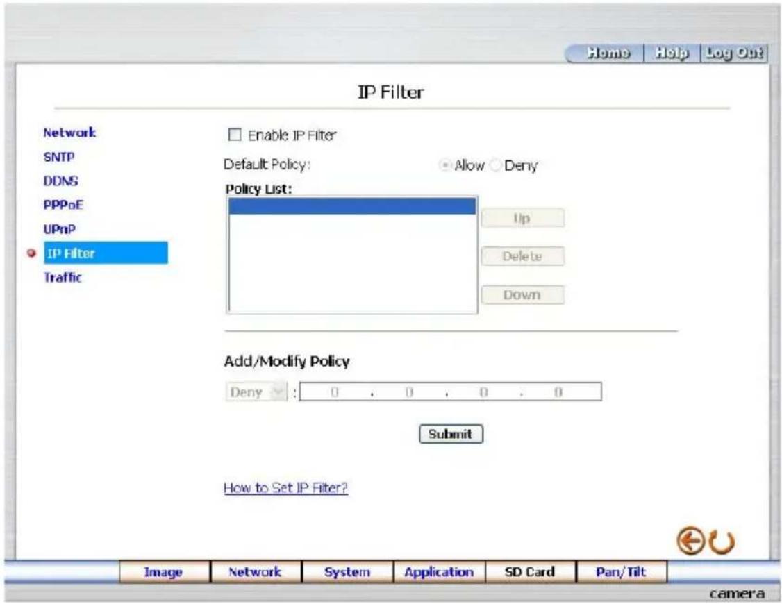
The "Network" page has, on its upper left, the "IP Filter" icon. Please follow the steps below to change the IP Filter setting through the network if necessary.
- Click the IP Filter button at upper left above to enter the "Network Setting" page.
text_image
Home Help Log Out IP Filter Network SNTP DDNS PPPoE UPnP IP Filter Traffic Enable IP Filter Default Policy: Allow Deny Policy List: Up Delete Down Add/Modify Policy Deny : 0 , 0 , 0 , 0 Submit How to Set IP Filter? Image Network System Application SD Card Pan/Tilt camera- Click "Enable IP Filter" to checkmark the attached box and activate the function.
- Select the Default policy.
- Set the Allow/Deny IP Filter policy and enter its IP address.
- After setting the policies, they will be shown on the Policy List. The user can use the "Up" or "Down" to select a policy and use the "Delete" button to erase it.
- Click the Submit button to submit the new setting.
- Click the Home button to return to the home page.
Note: The settings of the IP Filter must be correct or you may not able to operate the device regularly. In case of the wrong setting of the IP Filter and you can't access the device normally, please press the "Default" button on the rear panel of the camera for back to the factory default setting.
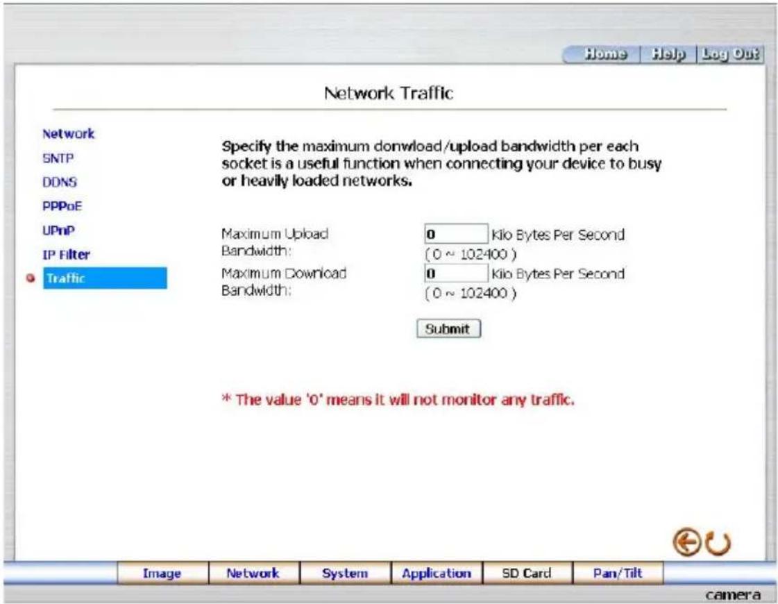
● Change the Network Setting —Network Traffic.
The "Network" page has, on its upper left, the "Traffic" icon. Please follow the steps below to change the UPnP setting through the network if necessary.
- Click the Traffic button at upper left above to enter the "Network Traffic" page.
text_image
Network Traffic Network SNTP DDNS PPPoE UPnP IP Filter Traffic Specify the maximum download/upload bandwidth per each socket is a useful function when connecting your device to busy or heavily loaded networks. Maximum Upload Bandwidth: Maximum Download Bandwidth: 0 Kilo Bytes Per Second (0 ~ 102400 ) 0 Kilo Bytes Per Second (0 ~ 102400 ) Submit * The value '0' means it will not monitor any traffic.- Type in the "Maximum Upload Bandwidth" and the "Maximum Download Bandwidth".
- Click the Submit button to submit the new setting.
- Click the Home button to return to the home page.
Description of function keys:
Maximum Upload Bandwidth: Enter it in the given space from a range of 0 to 102400.
Maximum Download Bandwidth: Enter it in the required space from a range of 0 to 102400.
Submit: Click to set.
5.1.4 Change the System Setting
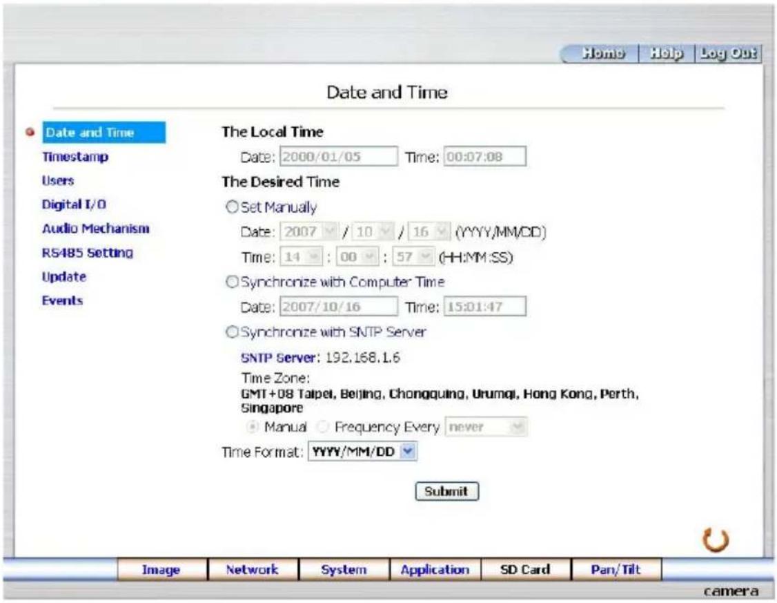
Please follow the steps below to change the date and time of the system setting through the network if necessary.
- Set the Date and Time of the system
- Click the System button in the home page to enter the "Date And Time" page (default).
text_image
Date and Time Date and Time Timestamp Users Digital I/O Audio Mechanism RS485 Setting Update Events The Local Time Date: 2000/01/05 Time: 00:07:08 The Desired Time Set Manually Date: 2007 / 10 / 16 (YYYY/MM/DD) Time: 14 : 00 : 57 (HH:MM:SS) Synchronize with Computer Time Date: 2007/10/16 Time: 15:01:47 Synchronize with SNTP Server SNTP Server: 192.168.1.6 Time Zone: GMT+08 Taipei, Beijing, Chongqing, Urumqi, Hong Kong, Perth, Singapore Manual Frequency Every never Time Format: YYYY/MM/DD Submit Image Network System Application SD Card Pan/Tilt camera- Choose one of the three modes shown on the page to set the Date and Time of the system. The three modes are "Set Manually", "Synchronize With Computer Time", and "Synchronize With SNTP Server".
- Click the Submit button to submit the new Date and Time settings.
- Click the Home button to return to the home page.
Description of function keys:
The Local Time: Shows the current date and time of the Network camera.
Set Manually: Manually sets the date and time of the Network camera.
Synchronize With Computer Time: Synchronizes with the linking computer.
Synchronize With SNTP Server: Synchronizes with the SNTP server. In this mode, two choices of adjusting are provided: doing it manually or setting the frequency to enable the system to do it automatically.
Submit: Click to submit the new setting to the Network camera.
● Change the System Setting — Timestamp.
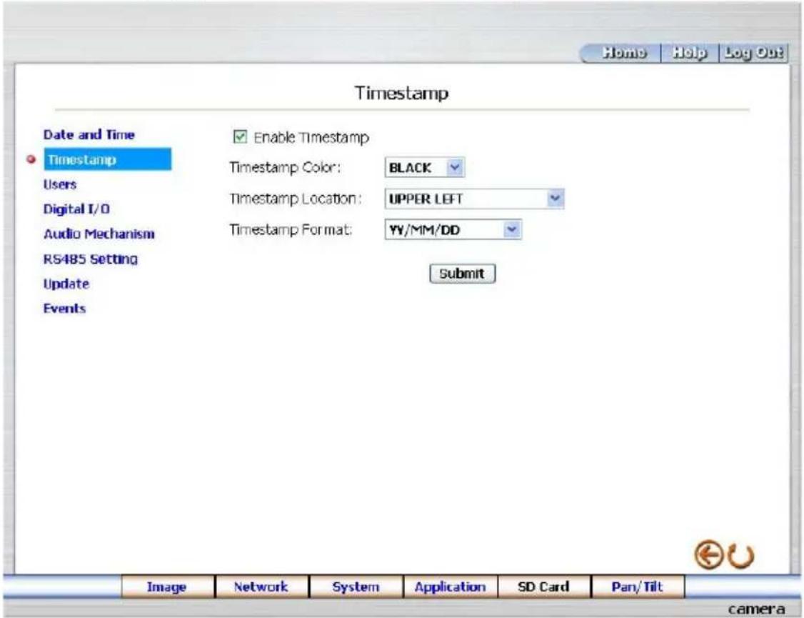
Please follow the steps below to change/add the timestamp through the network if necessary.
- Click the Timestamp button on the left side of the "System - Date and Time" page to enter the "System - Timestamp" page.
text_image
Home Help Log Out Timestamp Date and Time Timestamp Users Digital I/O Audio Mechanism RS485 Setting Update Events Enable Timestamp Timestamp Color: BLACK Timestamp Location: UPPER LEFT Timestamp Format: YY/MM/DD Submit Image Network System Application SD Card Pan/Tilt camera- Click "Enable Timestamp" to checkmark the attached box and activate the function
- Add or modify any timestamp's data if necessary.
- Enter the "Timestamp Color" you have chosen.
- Enter the "Timestamp Location" you have chosen.
- Enter the "Timestamp Format" you have chosen.
- Click the Submit button to submit the new user's setting.
- Click the Home button to return to the home page.
Description of function keys:
Enable Timestamp: Checkmark to activate the function.
Timestamp Color: Click to open the list of eight color modes to choose from: "BLACK", "WHITE", "RED", "ORANGE", "YELLOW", "GREEN", "BLUE", and "PURPLE".
Timestamp Location: Click to open the list of four location modes to choose from: "UPPER LEFT", "UPPER RIGHT", "BOTTOM LEFT", and "BOTTOM RIGHT".
Timestamp Format: Click to open the list of six format modes to choose from: "YY/MM/DD", "MM/DD/YY", "DD/MM/YY", "YY/MM/DD TITLE", "MM/DD/YY TITLE", and "DD/MM/YY TITLE".
Submit: Click to set.
● Change the System Setting — Users.
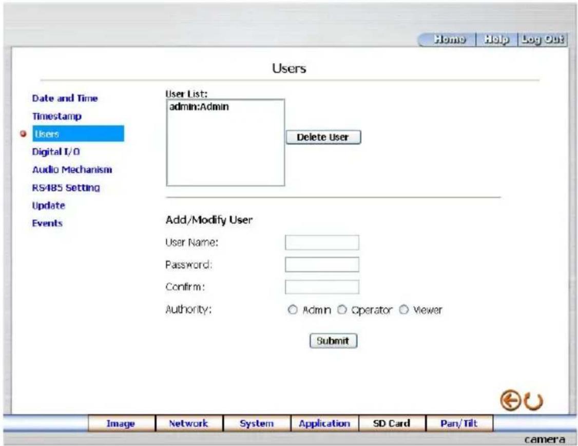
Please follow the steps below to change/add the users' authority through the network if necessary.
- Click the Users button on the left side of the "Date and Time" page to enter the "Users" page.
text_image
Home Help Log Out Users Date and Time Timestamp Users Digital I/O Audio Mechanism RS485 Setting Update Events User List: admin:Admin Delete User Add/Modify User User Name: Password: Confirm: Authority: ○ Admin ○ Operator ○ Viewer Submit Image Network System Application SD Card Pan/Tilt camera- Add, modify or delete any user's data if necessary.
- Click the Submit button to submit the new user's settings.
- Click the Home button to return to the home page.
Description of function keys:
User List: The list shows the registered user(s) and the corresponding authority.
Delete: Deletes a selected user.
Name: Enter the user's name, which will be added or modified.
Password: Enter the new password of the user's name above.
Confirm: Type in the password again for verification.
Authority: Choose an authority option of the user's name from: Admin, Operator, and Viewer.
Submit: Click to submit the new setting to the Network camera.
● Change the System Setting — Digital I/O.
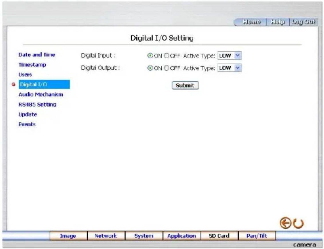
Please follow the steps below to change the Digital I/O through the network if necessary.
- Click the Digital I/O button on the left side of the "Date and Time" page to enter the "Digital I/O Setting" page.
text_image
Home Help Log Out Digital I/O Setting Date and Time Timestamp Users Digital I/O Audio Mechanism RS485 Setting Update Events Digital Input : Digital Output : ON OFF Active Type: LOW ON OFF Active Type: LOW Submit Image Network System Application SD Card Pan/Tilt camera- Mark the "Digital Input" "ON" or "OFF" and the "Digital Output" "ON" or "OFF". Click your choices to enable.
- Click the Submit button to submit the new user's settings.
- Click the Home button to return to the home page.
Description of function keys:
Digital Input: Select "ON" or "OFF" to use the GPIO connector or shut it down.
Digital Output: Select "ON" or "OFF" to use the GPIO connector or deactivate it.
● Change the System Setting — Audio Mechanism.
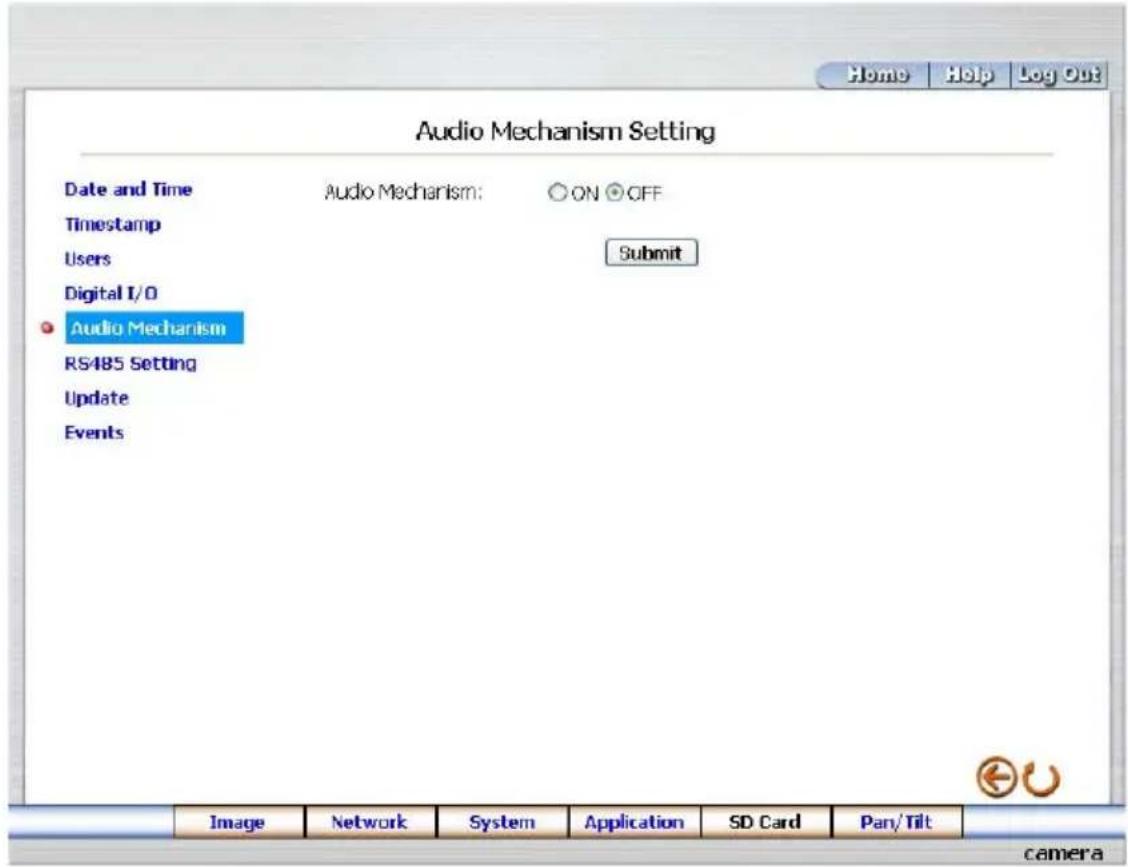
Please follow the steps below to change the Audio Mechanism through the network if necessary.
- Click the Audio Mechanism button on the left side of the "Date and Time" page to enter the "Audio Mechanism Setting" page.
text_image
Audio Mechanism Setting Date and Time Timestamp Users Digital I/O Audio Mechanism RS485 Setting Update Events Audio Mechanism: ON OFF Submit Image Network System Application SD Card Pan/Tilt camera- Mark the "Audio Mechanism" "ON" or "OFF".
- Click the Submit button to submit the new user's settings.
- Click the Home button to return to the home page.
NOTE: This setting is for turning the audio mechanism of the Camera on/off automatically. The Live audio service is only provided in the MPEG4 mode via the Web browser.
Description of function keys:
Audio Mechanism: Select "ON" or "OFF" to activate or deactivate the function.
● Change the System Setting — RS485 Setting.
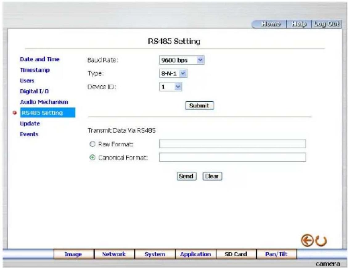
Click the RS485 Setting button on the left side of the "Date and Time" page to enter the "RS485 Setting" page.
text_image
Home Help Log Out RS485 Setting Date and Time Baud Rate: 9600 bps Timestamp Type: 8-N-1 Users Device ID: 1 Digital I/O Audio Mechanism Submit RS485 Setting Update Transmit Data Via RS485 Events Raw Format: Canonical Format: Send Clear Image Network System Application SD Card Pan/Tilt cameraDescription of function keys:
Baud rate: Eight different speeds can be used: 2400 baud per second, 4800 baud, 9600 baud, 19200 baud, 28800 baud, 38400 baud, 57600 baud and 115200 baud.
Type: Choose one of the types.
Device ID: You have the option of using an ID code (any number between 1 and 255).
Raw format: Set to transmit the ASCII codes.
Canonical format: Set to transmit the character string.
● Change the System Setting — Update Firmware.
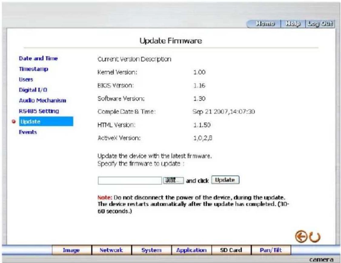
Please follow the steps below to update the firmware through the network if necessary.
- Click the Update Firmware button on the left side of the "Date and Time" page to enter the "Update Firmware" page.
text_image
Update Firmware Date and Time Current Version Description Timestamp Kernel Version: 1.00 Users BIOS Version: 1.16 Digital I/O Audio Mechanism Software Version: 1.30 RS485 Setting Comple Date & Time: Sep 21 2007,14:07:30 Update HTML Version: 1.1.50 Events ActiveX Version: 1,0,2,8 Update the device with the latest firmware. Specify the firmware to update : 浏览...and click Update Note: Do not disconnect the power of the device, during the update. The device restarts automatically after the update has completed. (30- 60 seconds.) Image Network System Application SD Card Pan/Tilt camera- Click the "Browse..." button to select the UPDATE.BIN file which was copied into your computer.
- Click the "Update" button.
- DO NOT power off the Network camera while this update process is running.
Note: Don't interrupt the process while the unit is updating itself.
Note: Please make sure that the UPDATE.BIN file is fit in with the model of the unit. Updating with the wrong UPDATE.BIN file may cause any physical damage to the device.
Note: The Temporary Internet Files (or cache) folder contains Web page content that is stored on your hard disk for quick viewing. We suggest deleting the Temporary Internet Files immediately after updating the firmware. To delete the files in the Temporary Internet Files folder, follow these steps:
- Quit Internet Explorer and quit any instances of Windows Explorer.
- Click Start, click Control Panel, and then double-click Internet Options.
- On the General tab, click Delete Files under Temporary Internet Files.
- In the Delete Files dialog box, click to select the Delete all offline content check box, and then click OK.
- Click OK.
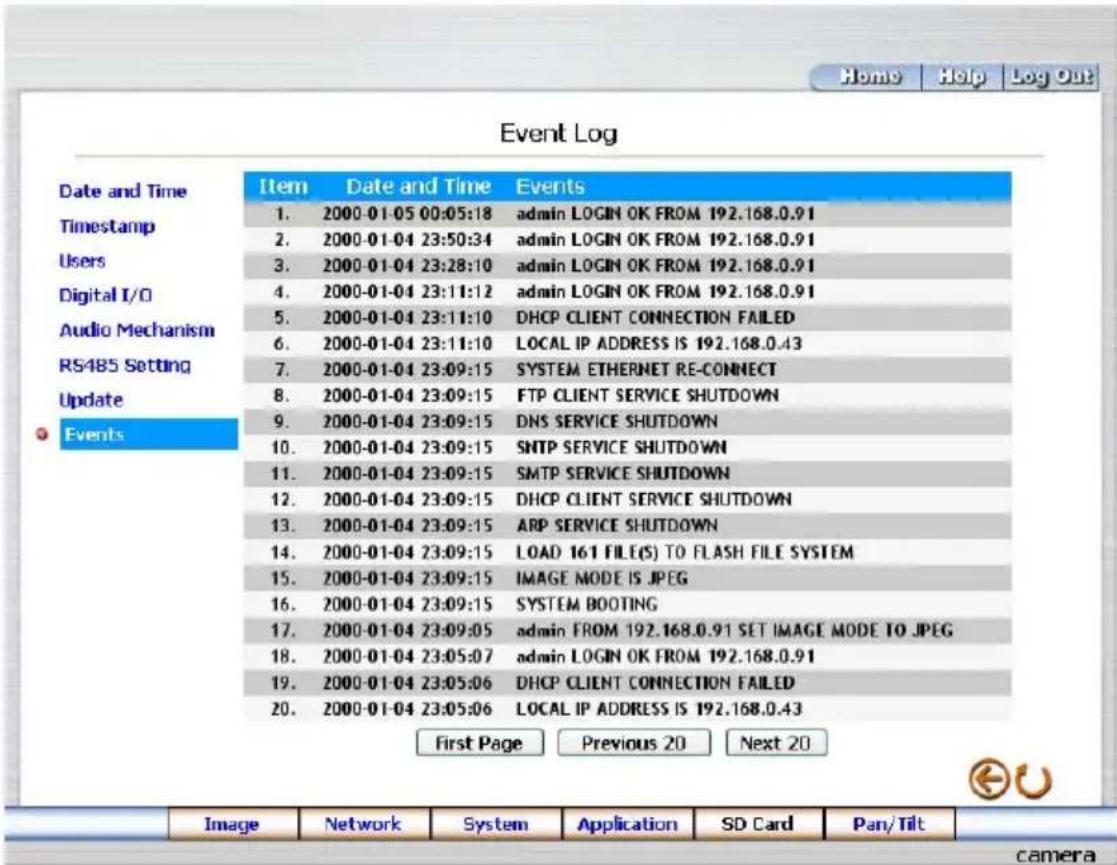
Please follow the steps below to view events through the network if necessary.
- Click the Events button on the upper left above to enter the "Event Log" page.
text_image
Home Help Log Out Event Log Date and Time Timestamp Users Digital I/O Audio Mechanism RS485 Setting Update Events Item Date and Time Events 1. 2000-01-05 00:05:18 admin LOGIN OK FROM 192.168.0.91 2. 2000-01-04 23:50:34 admin LOGIN OK FROM 192.168.0.91 3. 2000-01-04 23:28:10 admin LOGIN OK FROM 192.168.0.91 4. 2000-01-04 23:11:12 admin LOGIN OK FROM 192.168.0.91 5. 2000-01-04 23:11:10 DHCP CLIENT CONNECTION FAILED 6. 2000-01-04 23:11:10 LOCAL IP ADDRESS IS 192.168.0.43 7. 2000-01-04 23:09:15 SYSTEM ETHERNET RE-CONNECT 8. 2000-01-04 23:09:15 FTP CLIENT SERVICE SHUTDOWN 9. 2000-01-04 23:09:15 DNS SERVICE SHUTDOWN 10. 2000-01-04 23:09:15 SMTP SERVICE SHUTDOWN 11. 2000-01-04 23:09:15 SMTP SERVICE SHUTDOWN 12. 2000-01-04 23:09:15 DHCP CLIENT SERVICE SHUTDOWN 13. 2000-01-04 23:09:15 ARP SERVICE SHUTDOWN 14. 2000-01-04 23:09:15 LOAD 161 FILE(S) TO FLASH FILE SYSTEM 15. 2000-01-04 23:09:15 IMAGE MODE IS JPEG 16. 2000-01-04 23:09:15 SYSTEM BOOTING 17. 2000-01-04 23:09:05 admin FROM 192.168.0.91 SET IMAGE MODE TO JPEG 18. 2000-01-04 23:05:07 admin LOGIN OK FROM 192.168.0.91 19. 2000-01-04 23:05:06 DHCP CLIENT CONNECTION FAILED 20. 2000-01-04 23:05:06 LOCAL IP ADDRESS IS 192.168.0.43 First Page Previous 20 Next 20 Image Network System Application SD Card Pan/Tilt camera- Choose one of the three buttons shown on the page to view an event when necessary. The three buttons are titled "First Page", "Previous 20", and "Next 20".
Description of function keys:
First Page: Displays the first page.
Previous 20: Displays the previous 20 pages.
Next 20: Displays the next 20 pages.
5.1.5 Change the Application Setting
Please follow the steps below to change the application setting through the network if necessary.
● Change the Application Setting — SD Card Application Setting.
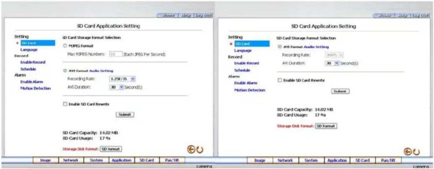
Please follow the steps below to change the SD CARD setting via the network if necessary to upload recording data live. Click the SD card button on the top left to enter the "SD Card Application Setting" page.
text_image
SD Card Application Setting Setting SD Card Language Record Enable Record Schedule Alarm Enable Alarm Motion Detection SD Card Storage Format Selection MJPEG Format Max MPEG Numbers: 10 (Each JPEG Per Second) AVI Format Audio Setting Recording Rate: 1.25F/35 AVI Duration: 30 Second(s) Enable SD Card Rewrite Submit SD Card Capacity: 14.02 MB SD Card Usage: 17 % Storage Disk Format: SD format SD Card Storage Format Selection AVI Format Audio setting Recording Rate: 2019 AVI Duration: 30 Second(s) Enable SD Card Rewrite Submit SD Card Capacity: 14.02 MB SD Card Usage: 17 % Storage Disk Format: SD formatSD Card setting page of MJPEG mode SD Card setting page of MPEG4 mode
- You have an option as to which SD - card storage format to use, the MJPEG (MJPEG mode only) or the AVI. Click your selected format and click "Submit" to set it.
- If it's MJPEG you want, fill in the "Max MJPEG Numbers" entry.
- If AVI is your choice, enter its recording rate and duration in seconds, and click "Submit" for their setting.
Description of function keys:
MJPEG Format: One image per file.
Max MJPEG Numbers: Sets the number of file sequences you can save per second.
AVI Format audio setting: Unlike a single – image file, this option offers a selected section of a video record.
Recording Rate: Sets your chosen frame rate of frames per second.
AVI Duration: Predetermines the length of each video file in terms of seconds.
Enable SD Card Rewrite: Tick to activate the SD card rewrite function.
SD Card Capacity: The free capacity of the SD card.
SD Card Usage: The percentage of the recorded file on the SD card.
SD Format: Click and press the Yes button to format the SD card.
- Change the Application Setting —Language Setting.
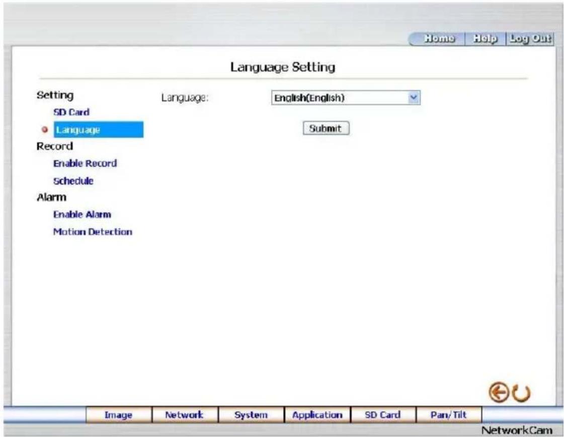
Please follow the steps below to change the Language setting via the network if necessary.
- Click the Language button on the left side to enter the "Language Setting" page.
text_image
Language Setting Setting SD Card Language Record Enable Record Schedule Alarm Enable Alarm Motion Detection Language: English(English) Submit Image Network System Application SD Card Pan/Tilt NetworkCam- You have an option as to which language to use. The default is "English"
- Click your selected language and click "Submit" to set it.
● Change the Application Setting — Record Application Enable Setting.
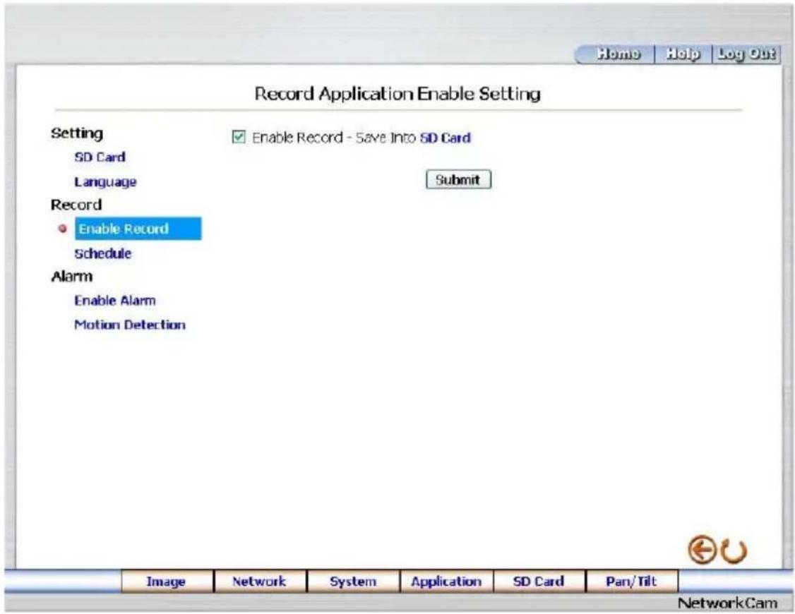
Please follow the steps below to change the setting via the network if necessary.
- Click the Enable Record button on the left side of the record to enter the "Record Application Enable Setting" page.
text_image
Record Application Enable Setting Setting SD Card Language Enable Record - Save Into SD Card Submit Record Enable Record Schedule Alarm Enable Alarm Motion Detection Image Network System Application SD Card Pan/Tilt NetworkCam- Click "Enable Record – Save Into SD Card" to checkmark the attached box and activate the function.
- Click the Submit button to submit the new setting of the recording.
- Click the Home button to return to the home page.
Description of function keys:
Enable Record – Save Into SD Card: Activates or deactivates the recording to the SD card.
● Change the Application Setting — Record - Schedule.
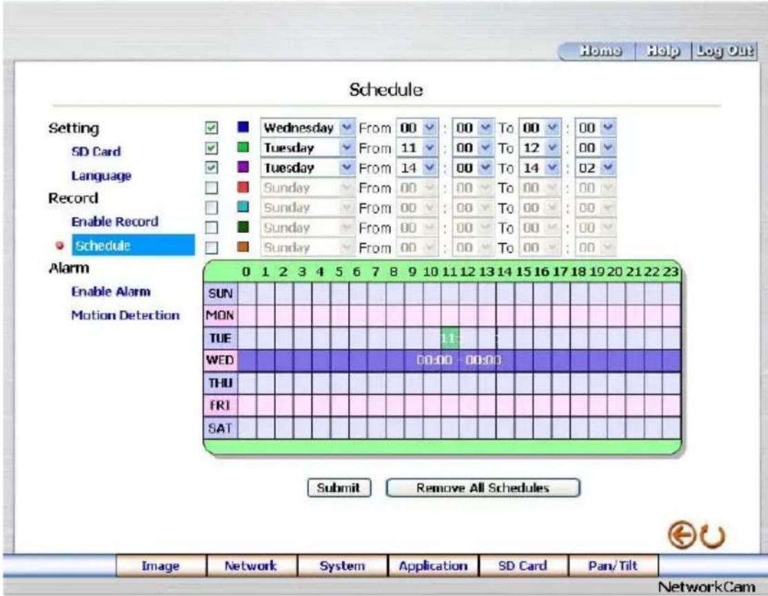
- Click the Application button on the home page to enter the "Record - Schedule" page.
text_image
Schedule Setting SD Card Language Record Enable Record Schedule Alarm Enable Alarm Motion Detection 0 1 2 3 4 5 6 7 8 9 10 11 12 13 14 15 16 17 18 19 20 21 22 23 SUN MON TUE WED THU FRI SAT Submit Remove All Schedules Image Network System Application SD Card Pan/Tilt NetworkCam- Check/uncheck any/all of the first seven boxes set vertically in the upper half of the "Schedule" page to enable/disable the programmed recording function, and vary the setting of the targeted item while it is enabled.
- Click the Submit button to submit the new schedule setting.
- Click the Remove All Schedules button to clear out all the data of the schedule setting.
Description of function keys:
Schedule: Check / uncheck the first seven boxes in a vertical row on the left to enable/disable the programmed scheduled recording function if necessary. Vary any of the schedules of the recording setting if necessary (please refer to the above description).
Chart: Schedule list.
Submit: Click to submit the new setting to the IP camera.
Remove All Schedules: Click to clear out all the data of the schedule setting.
● Change the Application Setting — Alarm Application Enable Setting.
Please follow the steps below to change the setting via the network if necessary.
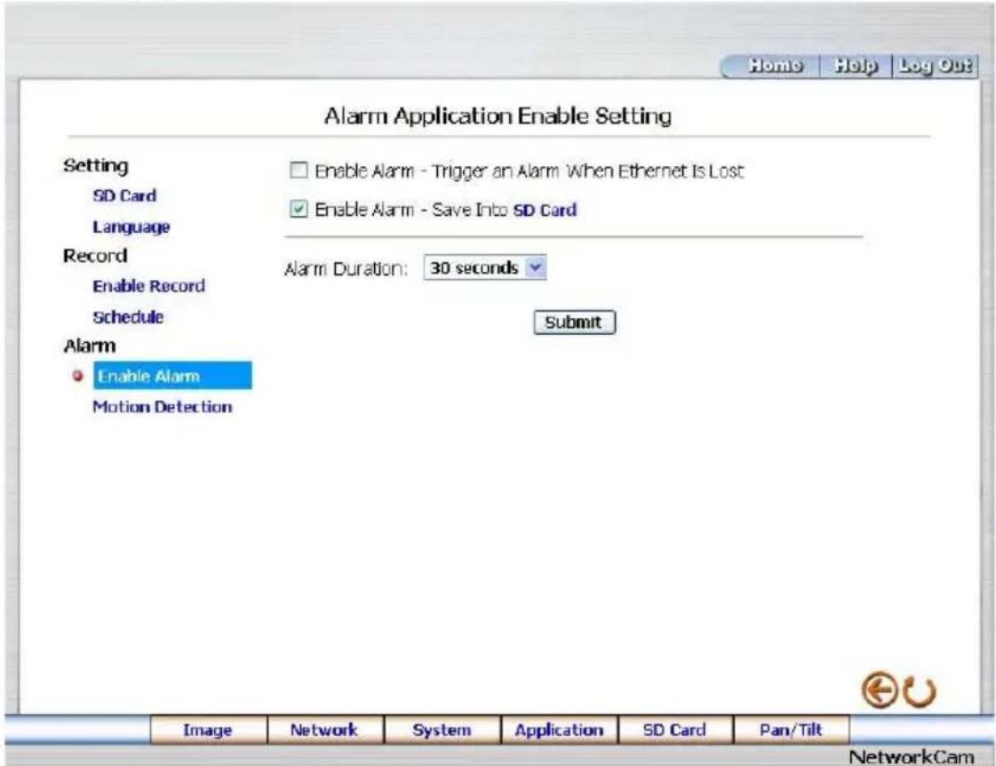
- Click the Enable Alarm button on the left side of the record to enter the "Alarm Application Enable Setting" page.
text_image
Home Help Log Out Alarm Application Enable Setting Setting SD Card Language Record Enable Record Schedule Alarm Enable Alarm Motion Detection Enable Alarm - Trigger an Alarm When Ethernet Is Lost Enable Alarm - Save Into SD Card Alarm Duration: 30 seconds Submit Image Network System Application SD Card Pan/Tilt NetworkCam- Click "Enable Alarm – Trigger an Alarm When Ethernet Is Lost" to checkmark the attached box and activate the function.
- Click "Enable Alarm – Save Into SD card" to checkmark the attached box and activate the function.
- Enter the "Alarm Duration" you have chosen.
- Click the Submit button to submit the new setting of the recording.
- Click the Home button to return to the home page.
Description of function keys:
Enable ALARM – Trigger an Alarm When Ethernet Is Lost: Activates or deactivates the alarm triggering while the Ethernet lost.
Enable Alarm – Save Into SD card: Activates or deactivates the alarm recording to be saved to the SD card.
Alarm Duration: Predetermines the length of the alarm.
● Change the Application Setting — Alarm - Motion Detection.
Please follow the steps below to enable changes in the motion detection function of the alarm through the network if necessary.
Set the motion detection:
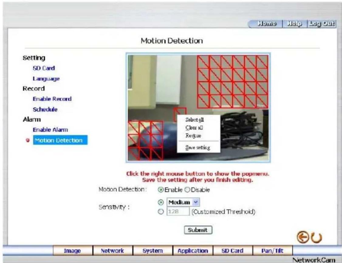
- Click the Motion Detection button on the left side of the Alarm to enter the "Alarm – Motion Detection" page.
text_image
Motion Detection Setting SD Card Language Record Enable Record Schedule Alarm Enable Alarm Motion Detection Select all Clear all Restore Save setting Click the right mouse button to show the popmenu. Save the setting after you finish editing. Motion Detection: Enable Disable Sensitivity: Medium 128 (Customized Threshold) Submit Image Network System Application SD Card Pan/Tilt NetworkCam- Click and drag the mouse across a targeted zone to draw a red rectangle on the image (coordinates provided below).
NOTE: You can set more than one targeted zone depending on your requirement.
- Enables / disables the motion detection function.
- Set up the signal level.
- Click the Submit button to submit the new setting of the recording.
- Click the Home button to return to the home page.
Description of function keys:
The targeted zone: Click and drag the mouse across the targeted zone to draw a red rectangle on the image.
Detection Range: The red rectangle's coordinates.
Save: Click to save the motion detection range.
Motion Detection: This option enables / disables the motion detection function.
Sensitivity Level: You can select any one of the given options for the setup signal level or just type in the value of Customized Threshold.
5.1.6 Change the SD card Setting
Please follow the steps below to change the SD card setting through the network if necessary.
● Change the SD card Setting — FILELIST of MEMORY CARD.
Please follow the steps below to change the setting via the network if necessary.
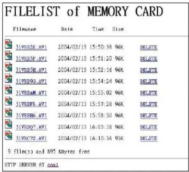
- Click the "SD card" button at the bottom of the home page to enter the page containing the "FILELIST of MEMORY CARD". The page comes in two modes, the JPEG and the AVI (please refer to the "SD card Application Setting Page").
text_image
FILELIST of MEMORY CARD Filename Date Time Size 3\VRE2E.AV1 2004/02/13 15:50:38 96K DELETE 3\VRE3P.AV1 2004/02/13 15:51:20 96K DELETE 3\VRE5H.AV1 2004/02/13 15:52:16 96K DELETE 3\VRE9G.AV1 2004/02/13 15:54:24 96K DELETE 3\VREAM.AV1 2004/02/13 15:55:02 96K DELETE 3\VREF8.AV1 2004/02/13 15:57:28 96K DELETE 3\VREH6.AV1 2004/02/13 15:58:30 96K DELETE 3\VREQ7.AV1 2004/02/13 16:03:18 96K DELETE 3\VRC7S.AV1 2004/02/13 16:10:36 93K DELETE 9 file(s) and 895 KBytes free HTTP SERVER AT coal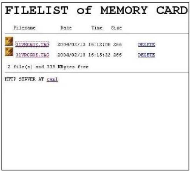
text_image
FILELIST of MEMORY CARD Filename Date Time Size 31VRCADZ.TAG 2004/02/13 16:12:08 266 DELETE 31VPCORE.TAG 2004/02/13 16:15:22 266 DELETE 2 file(s) and 339 KBytes free HTTP SERVER AT csa1- Click the desired file to display the images therein.
- Each file can be deleted by clicking the attached "DELETE" hyperlink.
NOTE: You can't directly click the hyperlink of the file in the "FILELIST of MEMORY CARD" page with the right button of the mouse focus and then click "SAVE" to save the file.
CAUTION: If you wish to save the SD CARD files from a camera to your computer, you can enter the JPEG column in the "FILELIST of MEMORY CARD" page to click in and enter the particular files in the column. When you click in, the images concerned will appear. Move your mouse focus within the image area and click the right button of the mouse. A table of item entries will show up. Click "Save" and select the path by which to save your files.
5.1.7 Change the Pan/Tilt setting
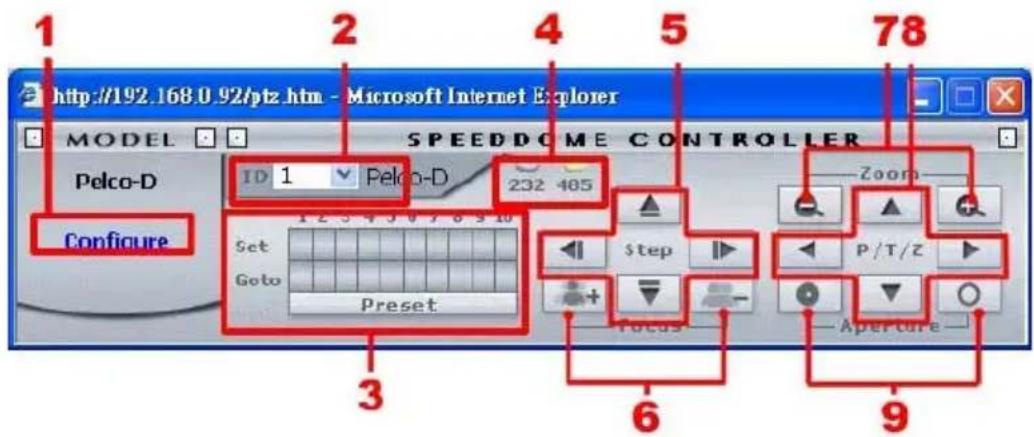
Click the Pan/Tilt button on the home page to open the Speed Dome Controller.
text_image
1 2 3 4 5 78 http://192.168.0.92/ptz.htm - Microsoft Internet Explorer MODEL SPEEDDOME CONTROLLER Pelco-D ID 1 Pelco-D 232 485 Configure Set Goto Preset Step Focus Zoom P/T/Z Aperture-
Click "Configure" to enter to the RS485 setting page (please refer to Change the System Setting — RS485 Setting).
-
Select a Speed Dome device ID from the drop-down list on the Speed Dome Controller. The Controller will display the corresponding ID.
-
Each of the ten buttons under 'Set' is connected with a specific position and angle of either panning or tilting of the camera. Click each button to activate its particular position and angle. Press the button under 'Preset' to turn the camera angle by angle in the set positions. Each of the ten buttons designated 'Go to' can be clicked to view the particular corresponding angle of the position in which it is set.
-
Select the connecting port. The RS-485 communication ports function as connectors when two or more units are serially connected to an external control device.
-
Upon the buttons being clicked, a camera will move one short step only in any of the four designated directions.
-
Click the buttons to control the Focus setting on the Speed Dome Controller. Click "+" button to focus far and click the "-" button to focus near.
-
Click the buttons to control the Zoom setting on the Speed Dome Controller. Click “+” button to zoom in and click the “-” button to zoom out.
-
Upon the buttons being clicked, a camera will turn all the way, without stopping, in one of the four designated directions.
-
Click the buttons to control the Aperture setting on the Speed Dome Controller.
5.1.8 PPPoE & DDNS
Using the PPPoE
- Install the XDSL software (obtained from your ISP dealer) in your PC.
- Search your IP camera's IP address: you can use your Network Viewer's Scan IP program, or just connect the ipxcam and the Video monitor. The monitor screen will show the IP address on its right side.
- Change the switch on the ipxcam's side panel to position # 4.
- Installing an IP address in your PC or notebook.
Desktop → Move the mouse focus to the Network neighborhood and click the right key of the mouse → Choose the properties → Choose your local connection → Choose the properties and select the configuration → Select the TCP / IP → Choose the properties → Type in the IP address in a four-part formula, for example “192. 168. 1.101” (the first three parts must be identical to the above numbers, only the last part can be changed to your own number, which must never exceed 255) → Click the mask and the mask input, namely “255. 255. 255. 0” (a fixed formula) → Click “OK” → Click “OK”.
- Desktop → Choose IE browser → Type in the IP camera IP address in the URL (check step #2 above) → Enter → ipxcam's images will appear.
PPPoE Settings
- Enter the IP camera home page → Choose the network → Type in "User Name: root" and "Password: Admin" → Click "OK".
- Choose PPPoE → PPPoE mode: Select "ON" → Type in "Account" → Type in "Password" → Submit → Unplug the power connection.
- Plug in the IP camera and it will receive an IP address from the ISP dealer (this IP address is dynamic --- every time you unplug and plug in again you'll get a new IP address).
Test: Go to the Internet.
- Set your PC to enter the Internet.
- Desktop → IE browser → Type in the IP camera IP address (the same address as in the PPPoE settings and step 3 above) → You can see the ipxcam's images.
DDNS settings
- Check your IP camera's IP address ( Scan IP software or monitor ) → open your IE browser → Use the address to connect to the ipxcam or view the images → Choose the network → Type in "User name : root" and "Password : Admin" → Click "OK".
- Choose the "DDNS" → Click "Enable DDNS" → Enter the "DDNS host name", for example "abc123.homeip.net" → Type in "DDNS Account", for example "abc123" → Enter the "DNS Password", for example "7777" → Submit → The settings are now complete → Close the IE browser.
- Open the IE browser again → Type in the Website address you just applied for, such as "abc123.homeip.net" → You can look at your IP camera images right away. The procedure is complete.
Note: These settings are only for your ADSL Dynamic IP configuration. If your configuration is fixed (true IP), you don't need to proceed with the PPPoE and DDNS settings. The DDNS is just for your convenience.
5.2 The IP camera IP Surveillance
This section provides instructions for installing and using the IP surveillance and Image Viewer, which are included with the IP camera. The programs can be operated by a selected PC equipped with the following requirements.
System Requirements
Intel Pentium 1.5 GHz processor or above (2.8 GHz or higher recommended).
● 128-MB RAM at least (256-MB or higher recommended).
● Windows 2000, XP or above.
● 4 MB VGA card capable of 24-bit true color display.
● 100 MB free hard-disk space for software installation.
● 10/100 Base-TX network for LAN operation.
● The Microsoft Internet Explorer 6 above.
In the multi-channel recording mode, the HD data transfer rates must be 66MB or above (100MB or higher recommended).
5.2.1 Introduction to IP surveillance
The IP surveillance allows you to access many units of the IP camera from a remote desktop or a laptop in a TCP/IP networking environment. It can perform the following functions.
• View live images from the IP camera.
● Store, search, and review recorded video from the PC, and SD card.
● Change a regular record, event record, and timer properties.
Before you are ready to view images from a desktop, you need to have your IP camera networked by obtaining a 10/100 base-TX Ethernet data cable (Standard RJ-45) to connect the IP camera to your LAN/WAN. Now enter the main menu to set the IP address.
5.2.2 Install the IP surveillance in your PC
Install the IP surveillance from the supported CD-R.
- Exit all applications currently running in the selected PC.
- Insert the supported CD in the CD-ROM drive. The program will execute the installation automatically. Follow the on-screen instructions to proceed with the rest of the installation procedure as they appear.
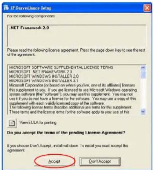
NOTE: It will update the .NET Framework to version 2.0 automatically. Please click "Accept" to continue.
text_image
IP Surveillance Setup For the following components: .NET Framework 2.0 Please read the following license agreement. Press the page down key to see the rest of the agreement. MICROSOFT SOFTWARE SUPPLEMENTALLICENSE TERMS MICROSOFT .NET FRAMEWORK 2.0 MICROSOFT WINDOWS INSTALLER 2.0 MICROSOFT WINDOWS INSTALLER 3.1 Microsoft Corporation (or based on where you live, one of its affiliates) licenses this supplement to you. If you are licensed to use Microsoft Windows operating system software (the "software"), you may use this supplement. You may not use it if you do not have a license for the software. You may use a copy of this supplement with each valid licensed copy of the software. The following license terms describe additional use terms for this supplement. These terms and the license terms for the software apply to your use of this View EULA to printing Do you accept the terms of the pending License Agreement? If you choose Don't Accept, install will close. To install you must accept this agreement. Accept Don'Accept- After the installation is complete, pop up the START menu from your computer, and point to Programs / IP surveillance / IP surveillance to open up the program selection page as shown below. Click the IP surveillance tag to start the IP surveillance program.
Install the IP surveillance for the ZIP file.
- Save the ZIP file to your PC and extract the file to a designated directory.
-
Open the extracted folder. The folder contains 1 file.
-
Click on the setup icon to execute the installation and then follow the on-screen instructions to proceed with the rest of the installation procedure.
-
After the installation is complete, click the START menu from your computer, and point to Programs / IP surveillance to start the IP surveillance program.
NOTE: Please make sure the TCP/IP communication software has been properly set and configured in your computer. To check your TCP/IP settings, please refer to section 4.5 (the TCP/IP configuration setting).
5.2.3 Login the Network camera software
Once the IP surveillance is executed, a Login prompter will appear. You must enter the default User Name: root, and the password: Admin in the respective spaces. Click the "OK" button and enter the console page of the IP surveillance: both the user name and password must be entered correctly. Click the "Cancel" button and exit the login of the Network Viewer.
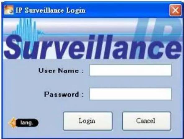
text_image
IP Surveillance Login Surveillance User Name : Password : lang. Login CancelView the Network camera video from a remote PC
Follow the instructions below to use the IP surveillance to browse a Network camera video from a remote location. Upon entering the IP surveillance, a connection box will appear as follows.
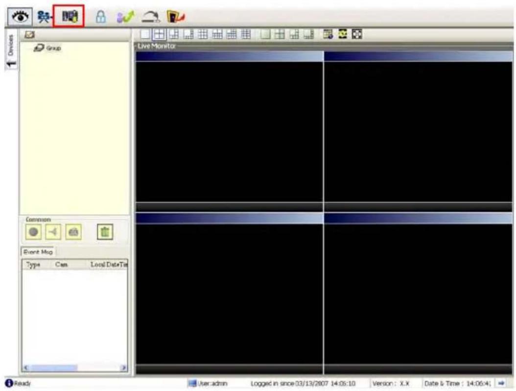
text_image
Live Monitor Common Event Map Type Can Local DataMap Ready User admin Logged in since 03/13/2007 14:06:10 Version: X.X Date & Time: 14:06:4- Press the
button to enter the Settings page.
-
Press the button to add a new device group. After typing in the Group Name, please press the OK button.
-
Add a channel from the button.
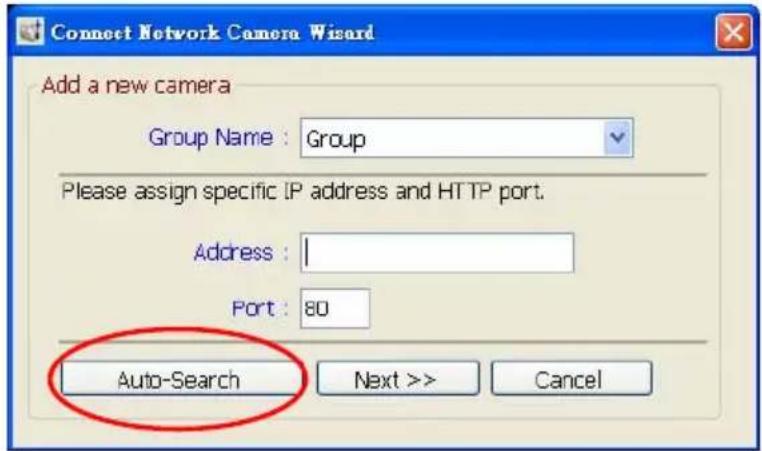
text_image
Connect Network Camera Wizard Add a new camera Group Name : Group Please assign specific IP address and HTTP port. Address : 1 Port : 80 Auto-Search Next >> Cancel- (1) Click the Auto-Search button at the bottom of the "Connect Network camera Wizard" page to discover the connection of the Network camera - type device in the LAN. Instantly the "Search Network camera" page will appear. Click the device of your choice and click "Select" at the bottom of the page to access the "Connect Network camera Wizard" page again.
(2) Type in the IP Address or the domain name and HTTP port of the device and add the device to the Device List.
- Type in the Password in the "Connect Network camera Wizard" page. Click "Next" button to open another "Add Device Wizard" page.
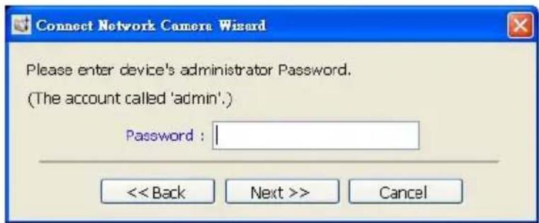
text_image
Connect Network Camera Wizard Please enter device's administrator Password. (The account called 'admin') Password :- This page provides the IP Address, the device type, and the MAC Address. After typing the Site name and selecting the Connect Mode, please click the "Next" button to access the next "Connect Network camera Wizard" page.
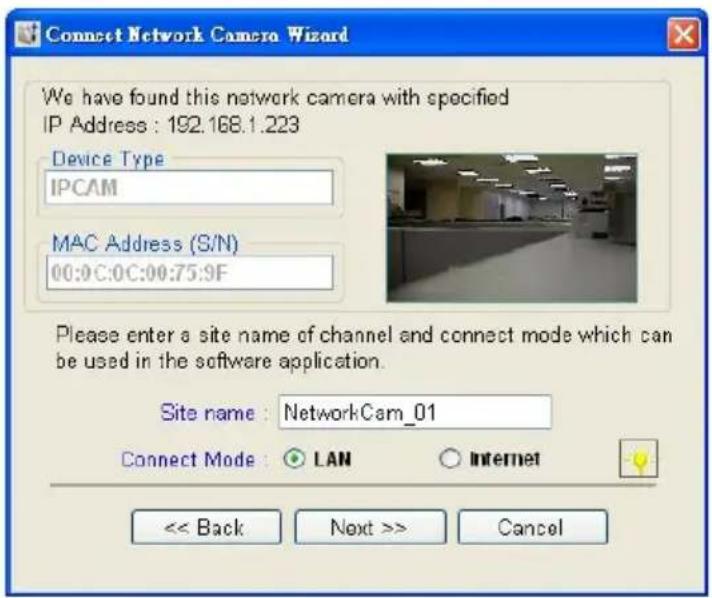
text_image
Connect Network Camera Wizard We have found this network camera with specified IP Address : 192.168.1.223 Device Type IPCAM MAC Address (S/N) 00:0C:0C:00:75:9F Please enter a site name of channel and connect mode which can be used in the software application. Site name : NetworkCam_01 Connect Mode : LAN Internet << Back Next >> CancelNOTE: Please click the 📊 icon to see the details of the Connect Mode.
- After finishing the setting of the Device Recording, please click the "Finish" button to establish the connection between the device and the computer.

text_image
Connect Network Camera Wizard Recording Quota Setting Free Recording Quota: 90 % (4711 Mb) Use Recording Quota: 10 % (523 Mb) Start to record after added this network camera. Record Mode Continuous Mode Event Mode Motion Alarm Sensor Alarm << Back Finish Cancel- Click the devise title to begin viewing images with this camera from the Device List.
NOTE: To add more connections or units to the Network camera, please repeat the above instructions.
5.2.4 Operation
5.2.4.1 Live Monitor
Once the connection has been established, click the button to enter the Live Monitor window. (See the sample screen below.) On the left side of the window is the connected device that has been arranged when you established the connection.
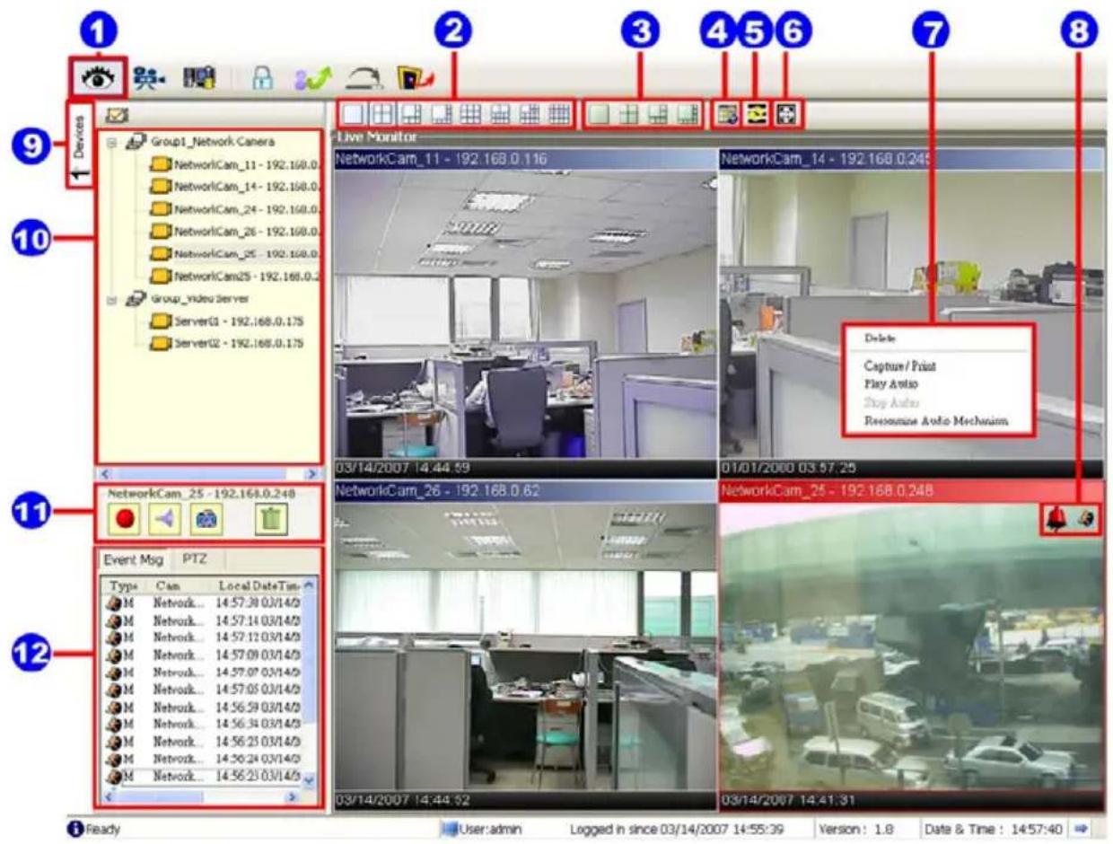
text_image
1 2 3 4 5 6 7 8 9 Devices Group1_Network_Camers NetworkCam_11 - 192.168.0.116 NetworkCam_14 - 192.168.0.245 Delete Capture/ Print Play Auto Stop Auto Resonize Audio Mechanism 10 Group_video_Server ServerG1 - 192.168.0.175 ServerG2 - 192.168.0.175 03/14/2007 14:44:59 01/01/2000 03:57:25 NetworkCam_25 - 192.168.0.248 NetworkCam_26 - 192.168.0.62 NetworkCam_25 - 192.168.0.248 03/14/2007 14:44:52 03/14/2007 14:41:31 Event Msg PTZ Type Cam Local DateTime M Network... 14:57:30 03/14/0 M Network... 14:57:14 03/14/0 M Network... 14:57:12 03/14/0 M Network... 14:57:09 03/14/0 M Network... 14:57:07 03/14/0 M Network... 14:57:05 03/14/0 M Network... 14:56:59 03/14/0 M Network... 14:56:34 03/14/0 M Network... 14:56:25 03/14/0 M Network... 14:56:24 03/14/0 Ready User: admin Logged in since 03/14/2007 14:55:39 Version: 1.8 Date & Time: 14:57:40- The Live Monitor icon.
◇Add a camera video onto the Live Monitor area:
(1) Click on the title of the camera that was connected.
(2) Hold down the right mouse button and drag onto the droppable Live Monitor area. The video from the new camera will be displayed.
(3) In the Live Monitor area, if you want to exchange the videos of different cameras, you can drag the video and drop it where you want to locate the video.
- The Split-Screen display function bar: This allows you to display the connected device in the single channel and multi-format screens.
- The Sequence configuring button: Press to enter the sequential jumping mode, each
multi-screen, and one sequence; the picture will sequentially switch to different channels according to the Sequence Views setting (refer to 5.2.4.3).
Note: One can't use the common icon (#11) in the Sequence displaying mode or drag the video and drop it as s/he likes. For the further settings of each channel, please select the device title on the left side and click the right mouse key to operate.
- The Circle configuring button: Click this button to see the following channels.
- The Group Circle button: Click this button to change the different group of display.
- The Full Screen button: Click this button to show the full screen for surveillance. If you want to return to the previous mode, please click the Normal Screen button.
- Motion on/ Alarm on: The warning icons.
Motion-on icon: When there is a detection of motion in any channel, it will display this icon in the right upper corner of that channel to warn the user.
Alarm on-icon: When there is a detection of external devices such as a sensor, it will display this icon on the upper right corner of that channel to warn the user.
- Pop-menu: You can use the mouse to move to each channel. Click the right key of the mouse to show a window. You can select "Delete", "Capture / Print", "Play/Stop Audio" or "Reexamine Audio Mechanism".
- Click this button to hide the "devices list", "common" and "alarm message list" boxes from view behind the video display screen.
- The section in the upper left margin will show the information in all the devices and its group names.
The users can click and hold on the device title on the list and drag it to the Live monitor area to see the live image of the camera.
- common icons:
Play Audio: Click the button to play the live audio. Click once again to deactivate.
Record: Click the button to archive AVI videos into your PC. Click once again to deactivate. In the recording mode, there will appear a red twinkling icon in the upper-right hand corner of the image.
Capture / Print: Provides the image capturing and printing functions.
Delete: Drop the view here to delete it.
◇Delete a camera video from the Live Monitor area:
(1) Select the video of the camera which you want to delete.
(2) Press and hold the left mouse button. Then drag it to the trashcan 📋 and release the mouse button.
- Alarm list / PTZ Control: Shows the alarm types, the device names and the occurrence time. You can press the PTZ button to change to the PTZ Control mode.
5.2.4.2 Playback Viewer
Press the button to enter the Playback Viewer setting page.
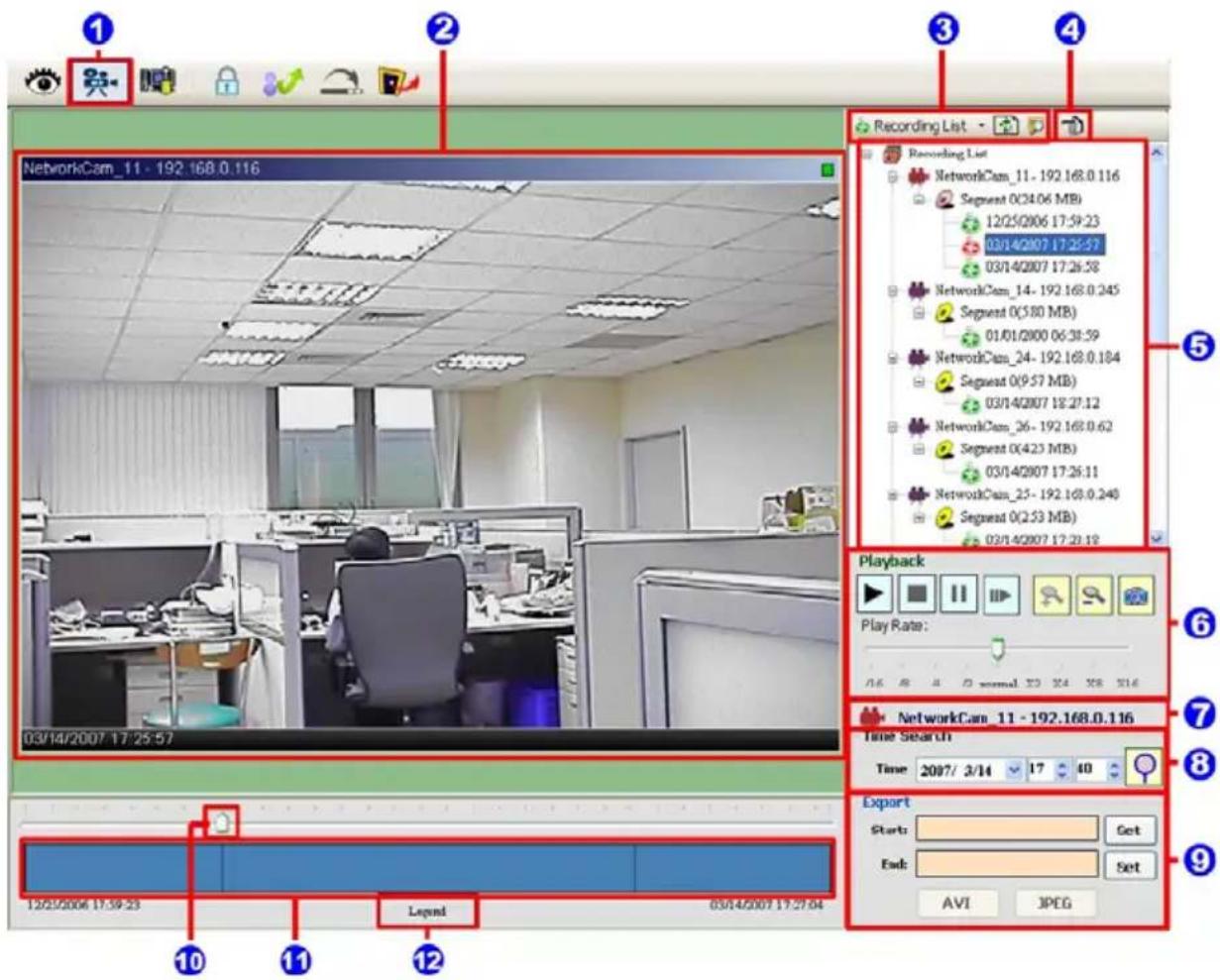
text_image
1 2 3 4 Recording List Recording List NetworkCam_11 - 192.168.0.116 Segment O(34.06 MB) 12/25/2006 17:59:23 03/14/2007 17:25:57 03/14/2007 17:26:58 NetworkCam_14 - 192.168.0.245 Segment O(580 MB) 01/01/2000 06:38:59 NetworkCam_24 - 192.168.0.184 Segment O(9.57 MB) 03/14/2007 18:27:12 NetworkCam_26 - 192.168.0.62 Segment O(4.23 MB) 03/14/2007 17:26:11 NetworkCam_25 - 192.168.0.248 Segment O(2.53 MB) 03/14/2007 17:29:18 Playback Play Rate: 16 A 4 C normal 70 X 24 X 8 X 16 NetworkCam_11 - 192.168.0.116 Time Search Time 2007/ 3/14 17 40 Export Start: End: AVI JPEG Legend 12/25/2006 17:39:23- The Playback Viewer icon.
- The display area.
- Click to choose the Recording List / Live Event Msg
Recording List Live Event Message
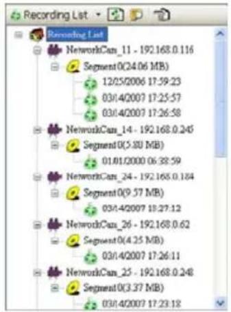
text_image
Recording List Recording List NetworkCan_11 - 192.168.0.116 Segment0(24.06 MB) 12/25/2006 17:59:23 03/4/2007 17:25:57 03/4/2007 17:26:58 NetworkCan_14 - 192.168.0.245 Segment0(5.80 MB) 01.01/2000 06:38:59 NetworkCan_24 - 192.168.0.184 Segment0(9.57 MB) 03/4/2007 18:27:12 NetworkCan_26 - 192.168.0.62 Segment0(4.25 MB) 03/4/2007 17:26:11 NetworkCan_25 - 192.168.0.248 Segment0(3.37 MB) 03/4/2007 17:23:18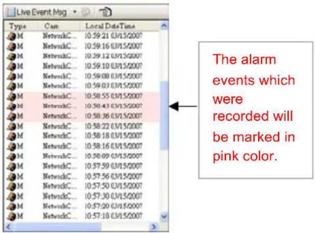
text_image
Live Event Mag Type Cam Local DateTime M NetworkC... 10:59:21 03/15/2007 M NetworkC... 10:59:16 03/15/2007 M NetworkC... 10:59:12 03/15/2007 M NetworkC... 10:59:10 03/15/2007 M NetworkC... 10:59:08 03/15/2007 M NetworkC... 10:59:03 03/15/2007 M NetworkC... 10:58:55 03/15/2007 M NetworkC... 10:58:43 03/15/2007 M NetworkC... 10:58:36 03/15/2007 M NetworkC... 10:58:22 03/15/2007 M NetworkC... 10:58:18 03/15/2007 M NetworkC... 10:58:16 03/15/2007 M NetworkC... 10:58:09 03/15/2007 M NetworkC... 10:57:59 03/15/2007 M NetworkC... 10:57:56 03/15/2007 M NetworkC... 10:57:50 03/15/2007 M NetworkC... 10:57:30 03/15/2007 M NetworkC... 10:57:20 03/15/2007 M NetworkC... 10:57:18 03/15/2007 The alarm events which were recorded will be marked in pink color.Click 📋 to refresh the recording list.
NOTE: To view the alarm lists of a camera which were recorded, please (1) click the icon (2) the Alarm List window will appear as shown below, (3) select a camera from the drop-down list, then (4) click the "Search" button.
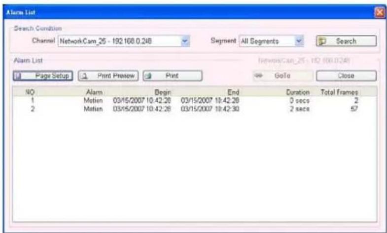
text_image
Alarm List Search Condition Channel NetworkCam_25 - 192.168.0.248 Segment All Segments Search Alarm List Page Setup Print Preview Print GoTo Close NO Alarm Begin End Duration Total frames 1 Motien 03/15/2007 10:42:28 03/15/2007 10:42:28 0 secs 2 2 Motien 03/15/2007 10:42:28 03/15/2007 10:42:30 2 secs 57- Move to the left/right area.
- Recorded video list box. This box allows you to access all recorded video, which are stored in the HDD of the connected devices.
- Playback function bar.
● Play - Click to a recorded video from the PLAY LIST.
- Stop - Click to stop playing back a recorded video or cease recording.
- Pause - Click to freeze the image.
Step - Click to view images picture-by-picture.
- Zoom in – Enlarges the displayed image.
- Zoom out - Narrows the displayed image.
● Capture / Print: Provides the image capturing and printing functions.
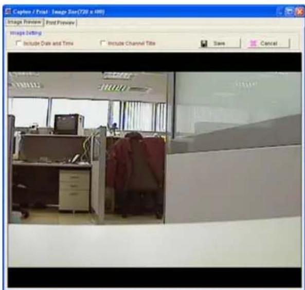
text_image
Capture / Print: Image Size (720 x 480) Image Preview Print Preview Image Setting Include Date and Time Include Channel Title Save Cancel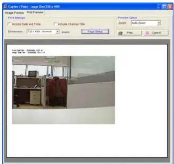
text_image
Capture / Print - Image Size(T20 x 400) Image Preview Print Preview Print Settings Include Delete and Time Include Channel Title Extension: T20 x 400 - Normal Preview Option Zoom Auto Zoom Print Cancel Print Size(T20 - 500) (100 x 40) Image Size(T20 - 500) (50 x 14)- Play Rate: During play mode, please use the scroll bar to control the show speed.
-
Shows the device title.
-
This allows you to search a recorded video kept in the HDD of the device. Enter the MONTH /DAY /YEAR /HOUR /MINUTE you wish to search and click 🔒 to proceed.
-
Functions to fit the starting and ending points of an image display, when the user wants to transfer a file.
JPEG: Archives images in the JPEG format to save a single picture in every file.
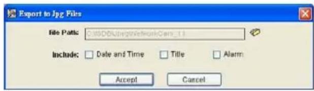
text_image
Export to Jpg Files File Path: C:\0000\bg#NetworkCam_13 Include: Date and Time Title Alarm Accept CancelAVI: Archives images in the AVI format to save a sequence of images in a file.
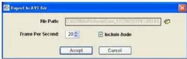
text_image
Export to AVI for File Path: C:\00\AvNetwork\Cap_11520070318-05143 Frame Per Second: 20 Include Audio Accept CancelWarning: The audio and video signals would likely be unable to play back simultaneously because of incomplete files caused by unstable network transmission or altered setup while doing the AVI backup with the "Include Audio" function.
-
Scroll bar for video searching: Drag the square on the bar to search the video. You can click or pull the indicator on the scroll bar to the point you want to see.
-
Displays the recording mode of the video on the histogram.
-
Press the Legend button to see the Histogram Legend. You can get the event's location in terms of time, and select a group of events or period from the event histogram area and show it on the display area.
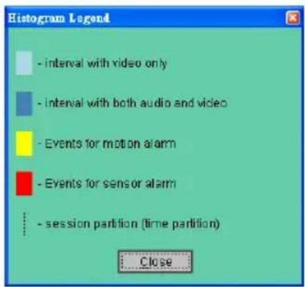
text_image
Histogram Legend - interval with video only - interval with both audio and video - Events for motion alarm - Events for sensor alarm - session partition (time partition) Close5.2.4.3 Setting
Press the button to enter the Setting page.
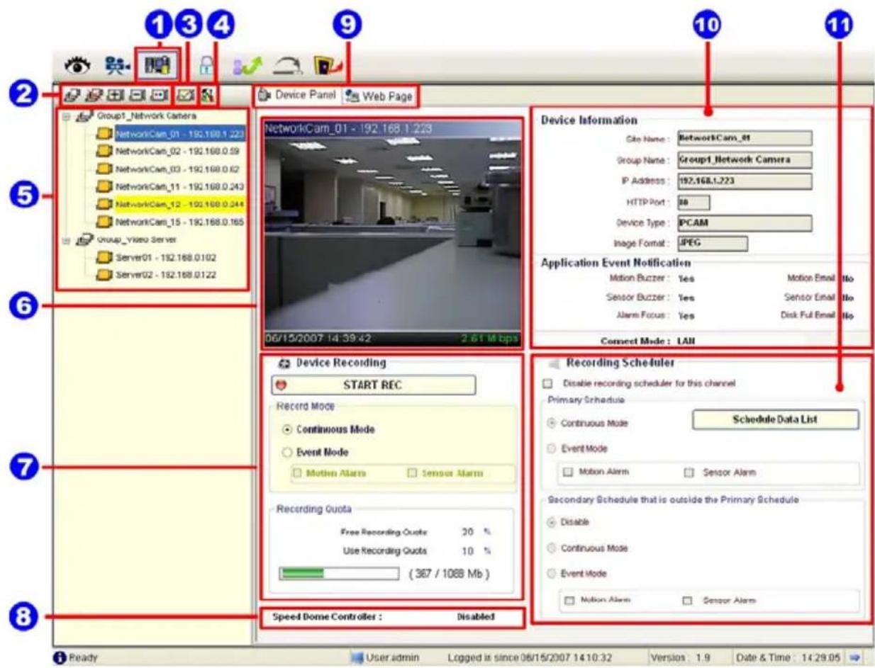
text_image
1 3 4 9 10 11 2 Group1_Network Camera NetworkCam_01 - 192.168.1.223 NetworkCam_02 - 192.168.0.59 NetworkCam_03 - 192.168.0.62 NetworkCam_11 - 192.168.0.243 NetworkCam_12 - 192.168.0.244 NetworkCam_15 - 192.168.0.165 Group_Video Server Server01 - 192.168.0.102 Server02 - 192.168.0.122 Device Panel Web Page 5 6 7 8 Device Information Cite Name: NetworkCam_81 Group Name: Group1_Network Camera IP Address: 192.168.1.223 HTTP Port: 88 Device Type: IPCAM Image Format: JPEG Application Event Notification Motion Buzzer: Yes Motion Email No Sensor Buzzer: Yes Sensor Email No Alarm Focus: Yes Disk Full Email No Connect Mode: LAH Device Recording START REC Record Mode Continuous Mode Event Mode Motion Alarm Sensor Alarm Recording Quota Free Recording Quota 30 % Use Recording Quota 10 % (367 / 108B Mb) Speed Dome Controller : Disabled Recording Scheduler Disable recording scheduler for this channel Primary Schedule Schedule Data List Continuous Mode Event Mode Motion Alarm Sensor Alarm Secondary Schedule that is outside the Primary Schedule Disable Continuous Mode Event Mode Motion Alarm Sensor Alarm Ready User admin Logged in since 06/15/2007 14:10:32 Versions: 1.9 Date & Time: 14:29:05-
The Setting page.
-
Function buttons:
-
Add a new device group: Click this button and type in the new group, then press "OK" to save it.
- Remove a device group: Click this button and select the group name, then press "OK" to delete the group.
- Add a new camera: For mode details please refer to section 5.2.3.
- Remove a camera: Click this button and select the group name and Network camera, then "OK" to delete the device.
● To edit camera: Please select a device, then click this button to edit the device.
3. Device Setting: Provides four pages of settings.
(1) Device Setting page (2) Image Setting page
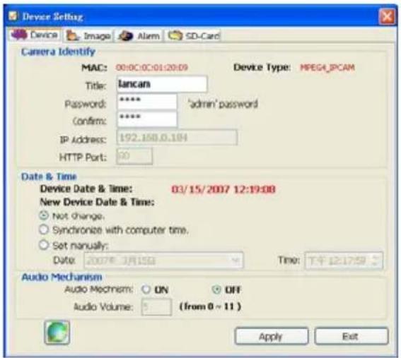
text_image
Device Setting Device Image Alarm SD-Card Camera Identify MAC: 00:00:00:01:20:09 Device Type: MPEG_IPCAM Title: lancan Password: **** 'admin' password Confirm: **** IP Address: 192.168.0.184 HTTP Port: 00 Date & Time Device Date & Time: 03/15/2007 12:19:08 New Device Date & Time: Not change. Synchronize with computer time. Set manually: Date: 2007年3月15日 Time: 下午12:17:59 Audio Mechanism Audio Mechanism: ON OFF Audio Volume: (from 0 ~ 11) Apply Exit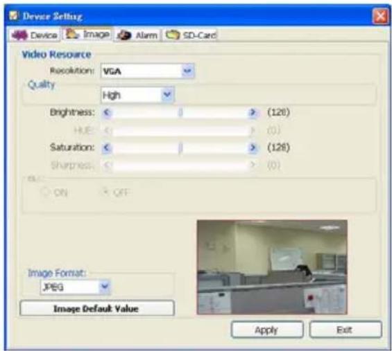
text_image
Device Setting Device Image Alarm SD-Card Video Resource Resolution: VGA Quality High Brightness: < > (128) HUE: < > (0) Saturation: < > (128) Sharpness: < > (0) ON OFF Image Format: JPEG Image Default Value Apply ExitNOTE: The IP Surveillance software connects the Internet to a Network camera. There may be a problem if the bandwidth is not enough, in which case the speed rate of the image transmissions may become too low. So if you want a satisfactory speed rate in your displays, you can click the “Device Setting” button, opening a “Device Setting” screen, and set the settings of the Device page where you can change the “Audio Mechanism” function to “OFF”. Turning it “OFF” will save the bandwidth from wastage, and improve the image display.
(3) Alarm Setting page (4) SD-card Setting page
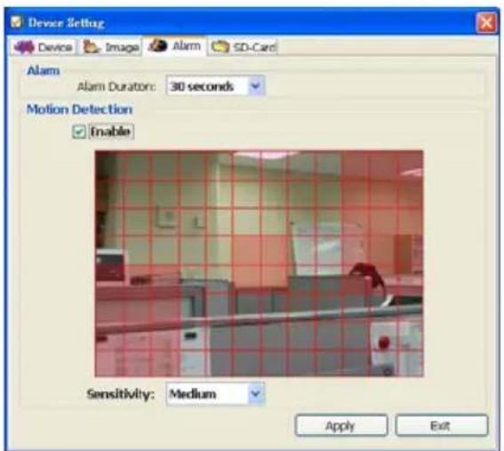
text_image
Device Setting Device Image Alarm SD-Card Alarm Alarm Duration: 30 seconds Motion Detection Enable Sensitivity: Medium Apply Exit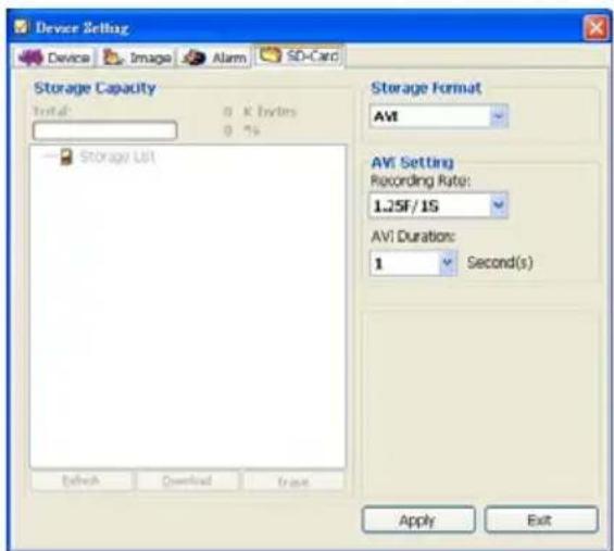
text_image
Device Setting Device Image Alarm SD-Card Storage Capacity Initial: 0 K bytes 0 %s Storage List Storage Format AM AVI Setting Recording Rate: 1.25F/15 AVI Duration: 1 Second(s) Apply ExitNOTE: Please remember to click the "Apply" button to save the settings.
- System Setting: Provides six pages of settings: the Global Settings, the Event Notification, the Recording Settings, the Scheduler, the Sequence Views, the Speed Dome and the Authority Setup.
(1) Global Settings
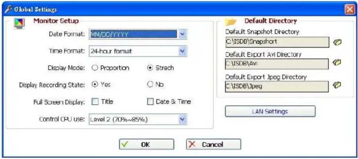
text_image
Global Settings Monitor Setup Date Format: MM/DD/YYYY Time Format: 24-hour format Display Mode: ○ Proportion ● Stretch Display Recording State: ○ Yes ○ No Full Screen Display: □ Title □ Date & Time Control CPU use: Level 2 (70%~85%) Default Directory Default Snapshot Directory C:\ISDB\Snapshort Default Export Avi Directory C:\ISDB\Avi Default Export Jpeg Directory C:\ISDB\Jpeg LAN Settings OK Cancel- Monitor setup: Sets the date/time mode and display mode, and controls the CPU use percentage on five levels.
Default Directory: Sets the default files' saving path. Click 📋 to select the directory.
(2) Event Notification
- Channel Prompt: Sets each camera to activate or deactivate the three modes of "Motion Buzzer", "Sensor Buzzer", and "Alarm Focus". Tick mark the blank space for each device to activate it.
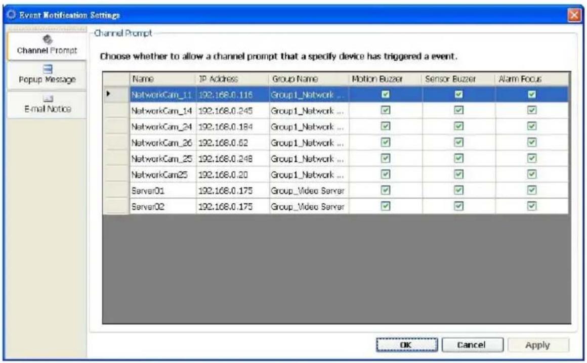
text_image
Event Notification Settings Channel Prompt Choose whether to allow a channel prompt that a specify device has triggered a event. Name IP Address Group Name Motion Buzzer Sensor Buzzer Alarm Focus NetworkCam_11 192.168.0.116 Group1_Network ... ✓ ✓ ✓ NetworkCam_14 192.168.0.245 Group1_Network ... ✓ ✓ ✓ NetworkCam_24 192.168.0.184 Group1_Network ... ✓ ✓ ✓ NetworkCam_26 192.168.0.62 Group1_Network ... ✓ ✓ ✓ NetworkCam_25 192.168.0.248 Group1_Network ... ✓ ✓ ✓ NetworkCam25 192.168.0.20 Group1_Network ... ✓ ✓ ✓ Server01 192.168.0.175 Group_Video Server ✓ ✓ ✓ Server02 192.168.0.175 Group_Video Server ✓ ✓ ✓ OK Cancel Apply- Popup Message: Sets the maximum number of the pop-up messages, the displaying time and the pop-up forms. Tick mark the blank space for each device to activate it.
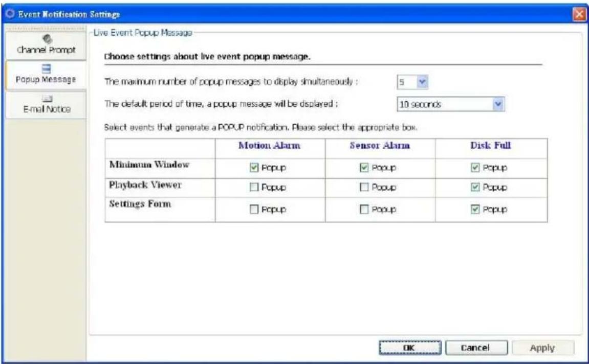
text_image
Event Notification Settings Channel Prompt Popup Message E-mail Notice Live Event Popup Message Choose settings about live event popup message. The maximum number of popup messages to display simultaneously : 5 The default period of time, a popup message will be displayed : 10 seconds Select events that generate a POPUP notification. Please select the appropriate box. Motion Alarm Sensor Alarm Disk Full Minimum Window ✓ Popup ✓ Popup ✓ Popup Playback Viewer □ Popup □ Popup ✓ Popup Settings Form □ Popup □ Popup ✓ Popup OK Cancel Apply- E-mail Notice: Sets each camera to activate the E-mail Notice function of the three situations: "Motion Alarm", "Sensor Alarm", and "DISK Full". Set the SMTP, the E-mail address and the attached file numbers to mail the user when the alarms occur. Tick mark the blank space for each device to activate it.
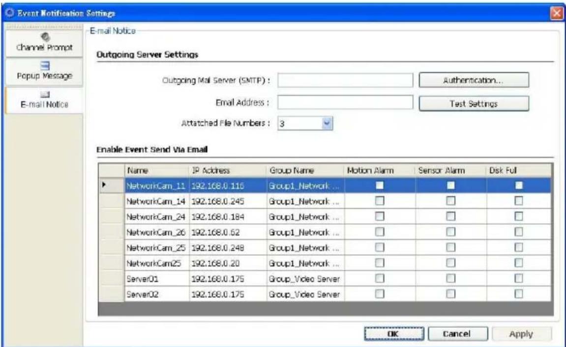
text_image
Event Notification Settings Channel Prompt Popup Message E-mail Notice E-mail Notice Outgoing Server Settings Outgoing Mail Server (SMTP) : Email Address : Attached File Numbers : 3 Authentication... Test Settings Enable Event Send Via Email Name IP Address Group Name Motion Alarm Sensor Alarm Disk Full NetworkCam_11 192.168.0.116 Group1_Network ... NetworkCam_14 192.168.0.245 Group1_Network ... NetworkCam_24 192.168.0.184 Group1_Network ... NetworkCam_26 192.168.0.62 Group1_Network ... NetworkCam_25 192.168.0.248 Group1_Network ... NetworkCam25 192.168.0.20 Group1_Network ... Server01 192.168.0.175 Group_Video Server Server02 192.168.0.175 Group_Video Server OK Cancel Apply(3) Recording Settings
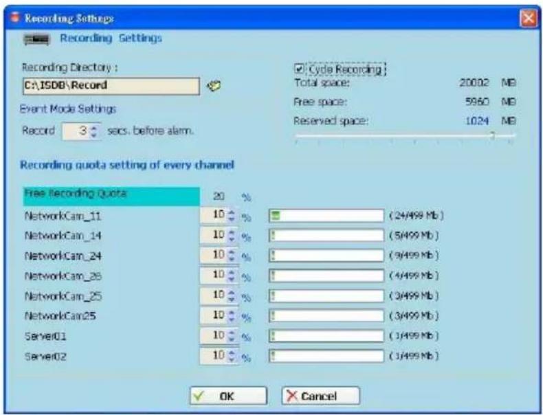
text_image
Recording Settings Recording Settings Recording Directory : C:\ISDB\Record Event Mode Settings Record 3 secs. before alarm. Recording quota setting of every channel Free Recording Quota 20 % NetworkCam_11 10 % (24/499 Mb) NetworkCam_14 10 % ! (5/499 Mb) NetworkCam_24 10 % ! (9/499 Mb) NetworkCam_28 10 % ! (4/499 Mb) NetworkCam_25 10 % ! (3/499 Mb) NetworkCam25 10 % ! (3/499 Mb) Server01 10 % ! (1/499 Mb) Server02 10 % ! (1/499 Mb) ✓ OK ✗ Cancel● Recording Settings: You can control the HDD reserved space by using the scroll bar.
● Recording quota setting: Set the maximum recording quota of each channel.
(4) Scheduler
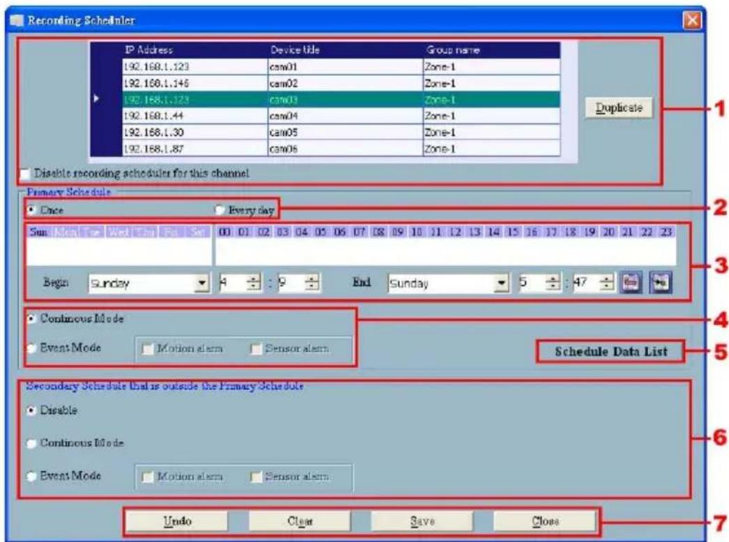
text_image
Recording Scheduler IP Address Device title Group name 192.168.1.123 cam01 Zone-1 192.168.1.146 cam02 Zone-1 192.168.1.123 cam03 Zone-1 192.168.1.44 cam04 Zone-1 192.168.1.30 cam05 Zone-1 192.168.1.87 cam06 Zone-1 Duplicate Disable recording scheduler for this channel Primary Schedule Once Every day Sun Wed Fri Fri Fri 00 01 02 03 04 05 06 07 08 09 10 11 12 13 14 15 16 17 18 19 20 21 22 23 Begin Sunday End Sunday 5 : 47 Continuous Mode Event Mode Motion alarm Sensor alarm Schedule Data List Secondary Schedule that is outside the Primary Schedule Disable Continuous Mode Event Mode Motion alarm Sensor alarm Undo Clear Save Close(1) Choose one of the devices to set its recording schedule.
(2) Select the period: Click to set to record only once or record every day.
(3) Select the recording time: Sets the periods of time in recording.
Select the Begin time and the End time the time markers will display above. Please use the up (increase) and down (decrease) arrows to adjust the setting.

Add the selected period schedule. You can also hold down the left mouse button to g a period.

Erase the selected period schedule. You can also use the right mouse button to cel the period.
(4) Select the recording mode.
(5) Press to show the scheduled recording list.
(6) Set the secondary schedule: Activate or inactivate the other recording modes besides the primary schedule.
(7) Option buttons:
Undo: Undo the latest changes.
Clear: Clear all the schedule markers in the current editing area.
Save: Apply the changes.
Close: Close the window.
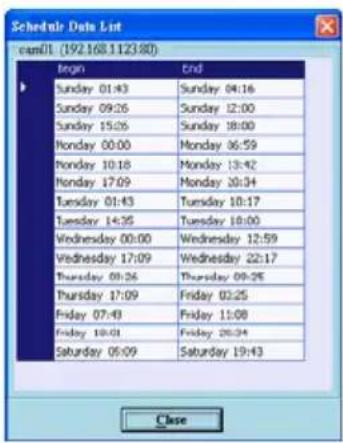
text_image
Schedule Data List email: (192.168.1123:80) Begin End Sunday 01:43 Sunday 04:16 Sunday 09:26 Sunday 12:00 Sunday 15:26 Sunday 18:00 Monday 00:00 Monday 06:59 Monday 10:18 Monday 13:42 Monday 17:09 Monday 20:34 Tuesday 01:43 Tuesday 10:17 Tuesday 14:35 Tuesday 18:00 Wednesday 00:00 Wednesday 12:59 Wednesday 17:09 Wednesday 22:17 Thursday 00:26 Thursday 09:26 Thursday 17:09 Friday 03:25 Friday 07:43 Friday 11:08 Friday 18:01 Friday 26:34 Saturday 05:09 Saturday 19:43 Close(5) Sequence Views
This function enables you to use four modes to set the sequence of displays you want for the
Sequence Mode of the Live Monitor.
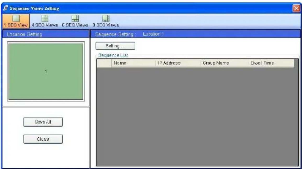
text_image
Sequence Views Setting 1 SEQ View 4 SEQ Views 6 SEQ Views 8 SEQ Views Location Setting 1 Save All Close Sequence Setting: Location 1 Setting ... Sequence List Name IP Address Group Name Dwell TimeThe user has to modify the "Sequence Views Setting" to make it work. For example, if you want to see the 4-window sequence, please follow the steps given below:
Step 1: Click the Sequence Views button to enter the Sequence Views setting page.
Step 2: Select the “4 SEQ views” and the ☐ 4-windows will show in the Location Setting area.
Step 3: Select one of the four channels (Location1-4), then click the "Setting" button.
Step 4: The 4 SEQ View(s) page will show below. Choose the device(s) and set the Dwell Time (3-30 seconds) from the drop-down list, then press the "Confirm" button.
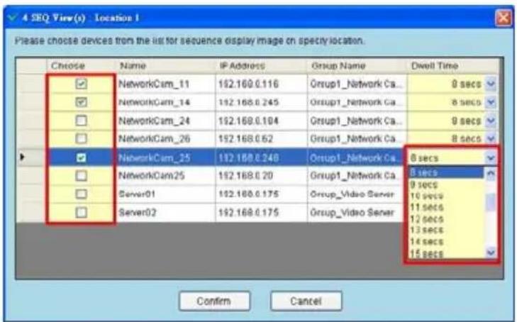
text_image
4 SEQ View(s) - Location 1 Please choose devices from the list for sequence display image on specy location. Choose Name IP Address Group Name Dwell Time NetworkCam_11 192.168.0.116 Group1_Network Ca... 8 secs NetworkCam_14 192.168.0.245 Group1_Network Ca... 8 secs NetworkCam_24 192.168.0.104 Group1_Network Ca... 8 secs NetworkCam_26 192.168.0.62 Group1_Network Ca... 8 secs NetworkCam_25 192.168.0.240 Group1_Network Ca... 8 secs NetworkCam25 192.168.0.20 Group1_Network Ca... 9 secs Server01 192.168.0.175 Group_Video_Sener... 10 secs Server02 192.168.0.175 Group_Video_Sener... 11 secs Confirm CancelStep 5: Set the other channels as in step 3-4.
Step 6: Click "Save all" button, then press "Close" button to exit the setting page.
Step 7: Open the Live Monitor page, then click the (4 SEQ views) button to see the 4-window sequence.
(6) Speed Dome
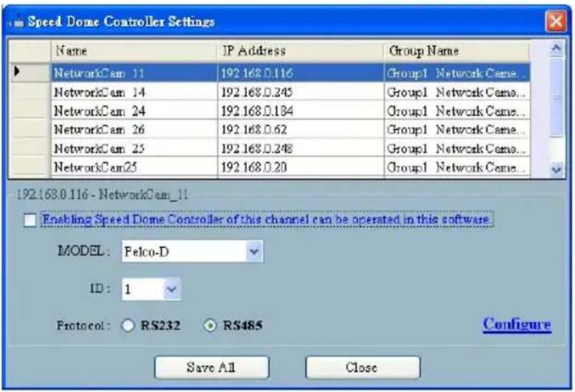
text_image
Speed Dome Controller Settings Name IP Address Group Name NetworkCam 11 192.168.0.116 Group1 Network Came... NetworkCam 14 192.168.0.245 Group1 Network Came... NetworkCam 24 192.168.0.184 Group1 Network Came... NetworkCam 26 192.168.0.62 Group1 Network Came... NetworkCam 25 192.168.0.248 Group1 Network Came... NetworkCam25 192.168.0.20 Group1 Network Came... 192.168.0.116 - NetworkCam_11 Enabling Speed Dome Controller of this channel can be operated in this software. MODEL: Felco-D ID: 1 Protocol: RS232 RS485 Configure Save All Close- Tick mark to activate the Speed Dome Controller function of the selected channel. The user can set the model, ID and the protocol here.
- Click "Configure" to enter to the RS485 setting page.
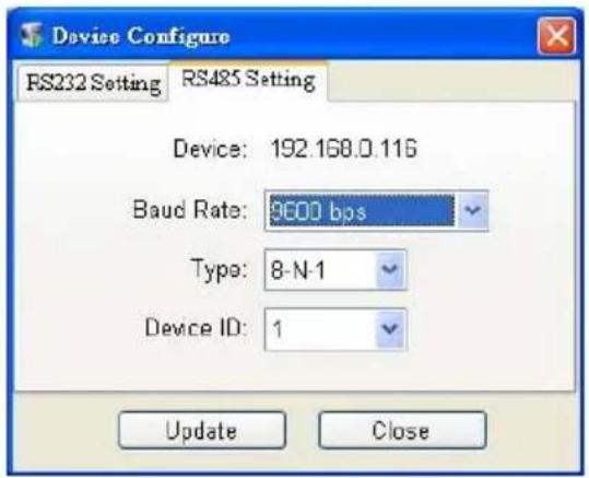
text_image
Device Configure RS232 Setting RS485 Setting Device: 192.168.0.116 Baud Rate: 9600 bos Type: 8-N-1 Device ID: 1 Update Close(7) Authority Setup
Authority setup: Change or add the user's authority. There are three different levels of authority, namely Admin, Operator and Viewer.
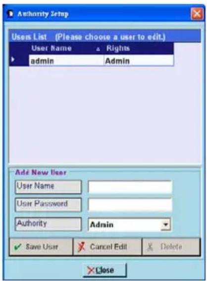
text_image
Authority Setup Users List (Please choose a user to edit.) User Name Rights admin Admin Add New User User Name User Password Authority Admin ✓ Save User Cancel Edit Delete × Close- List of cameras and its groups:
The users can use the icons above the list to change the groups' names, the devices' titles and the channels' display modes.
- Display area: Click the title of the camera, and you will see the live image in this area.
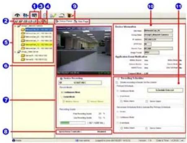
text_image
1 3 4 9 10 11 2 3 4 5 6 7 8 Device Panel View Page Device Name: NetworkView, No. Storage Date: Broadcast, Broadcast Currency IP Address: 100 MHz/1.0GHz Application Event Recommendation: A: 100 MHz B: 100 MHz C: 100 MHz D: 100 MHz E: 100 MHz F: 100 MHz G: 100 MHz H: 100 MHz I: 100 MHz J: 100 MHz K: 100 MHz L: 100 MHz M: 100 MHz N: 100 MHz O: 100 MHz P: 100 MHz Q: 100 MHz R: 100 MHz S: 100 MHz T: 100 MHz U: 100 MHz V: 100 MHz W: 100 MHz X: 100 MHz Y: 100 MHz Z: 100 MHz W: 100 MHz X: 100 MHz Y: 100 MHz Z: 100 MHz W: 100 MHz X: 100 MHz Y: 100 MHz Z: 100 MHz W: 100 MHz X: 100 MHz Y: 100 MHz Z: 155 MHz W: 155 MHz X: 155 MHz Y: 155 MHz Z: 155 MHz W: 155 MHz X: 155 MHz Y: 155 MHz Z: 155 MHz W: 155 MHz X: 155 MHz Y: 155 MHz Z: 155 MHz-
Device Recording: Click the "Start Record" button to start the recording mode and click the "Config Record" button to set the details of the recording below.
-
Status of the speed dome controller.
-
You can interchange between two buttons here: the "Device Panel" and "Web page" buttons.
The web page (please refer to section 5.1 for more details):
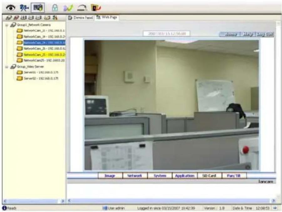
text_image
Group1_network_Covers NetworkCam_31 - 192.168.0.1 NetworkCam_34 - 192.168.0.2 NetworkCam_24 - 192.168.0.1 NetworkCam_25 - 192.168.0.2 NetworkCam25 - 192.168.0.20 Group_Micro_Server Server01 - 192.168.0.175 Server02 - 192.168.0.175 2007/03/15 12:56:08 Home | Nlty | Buy 001 Image Network System Application SD Card Pan/Tib loncam Read User admin Logged in since 03/15/2007 10:42:39 Version | 1.9 Date & Time 12:08:53-
Device information: The user can read a camera's information, such as "Site Name", "Group Name", "IP Address", "HTTP Port", "Device type", "Monitor Alarm Process" and the "Connect Mode".
-
Recording Scheduler: Shows the recording information of the selected channel.
5.2.4.4 Lock
Press the 🔍 button to lock the operation of this software, and the IP Surveillance monitor will be minimized into the systray*of the Windows taskbar. To unlock the command, please click the 🔍 button once, then type in the correct password.
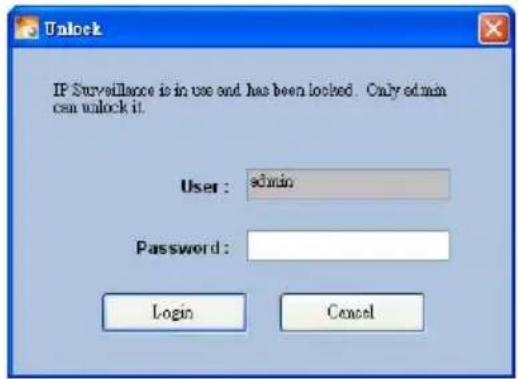
text_image
Unlock IF Surveillance is in use and has been locked. Only admin can unlock it. User : admin Password : Login Cancel*: The Microsoft Windows systray is a portion of the Windows 95, Windows 98, Windows ME, Windows NT, Windows 2000, and Windows XP Operating Systems that helps display running programs. The systray is located on the taskbar and is commonly in the bottom right hand corner of the screen next to the time display.
5.2.4.5 Logout
Press the 📁 button to logout the IP Surveillance software and the IP Surveillance monitor will be minimized into the systray of the Windows taskbar.
If you want to return to the IP Surveillance monitor, please click the button once, then select the page which you want to get into.
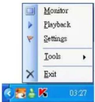
text_image
Monitor Playback Settings Tools ExitAfter typing in the correct user name and password, you can re-login to the software.
5.2.4.6 Tray
Press the button to minimize the IP Surveillance monitor into the systray of the Windows taskbar.
Click the button once to go back to the IP surveillance software.
5.2.4.7 Exit Setting
Press the button to exit the IP surveillance monitor which is minimized into the sysray of the Windows taskbar. Click the button to select the functions on the list.
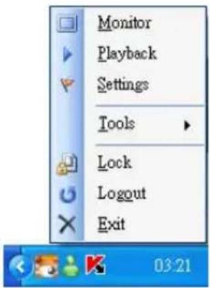
text_image
Monitor Playback Settings Tools Lock Logout ExitYou can also change the password by clicking the "Tools" and "Change password" items on the list. Enter the old password once and the new password twice, then press the "OK" button to save it.
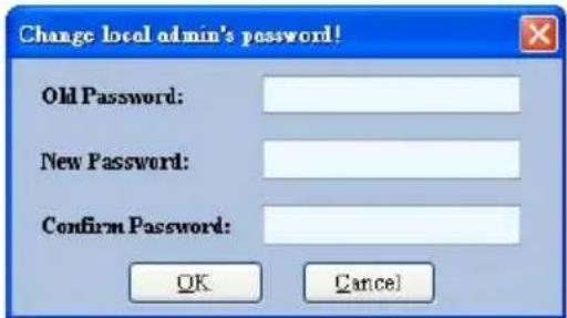
text_image
Change local admin's password! Old Password: New Password: Confirm Password: OK Cancel5.2.4 The Image Viewer
The Network camera is equipped with a digital watermark. It's a checking software which protects archived images and informs you whether the images have been modified or not. Follow the instructions below to open an archived image from an SD card or an HDD.
This is image integrity-protection software. It not only allows you to view an archived image from the SD card or HDD of a computer, but also protects an archived image from reproduction or interpolation. If an image isn't in the original format made by a Network camera, the Image Viewer will not display the image and instead will send a warning message, " Not Correct Image ", right away. Close this message to enable you to see the image now.
- Pop up the START menu in your computer, and point to Programs / IP surveillance / Tools to open up the program selection page. Click the Image Viewer tag to start the Image Viewer program (see a sample screen below).
- Click the RELOAD tag to load the images from a path.
- Click the PRINT tag to get a displayed image printed out from a printer.
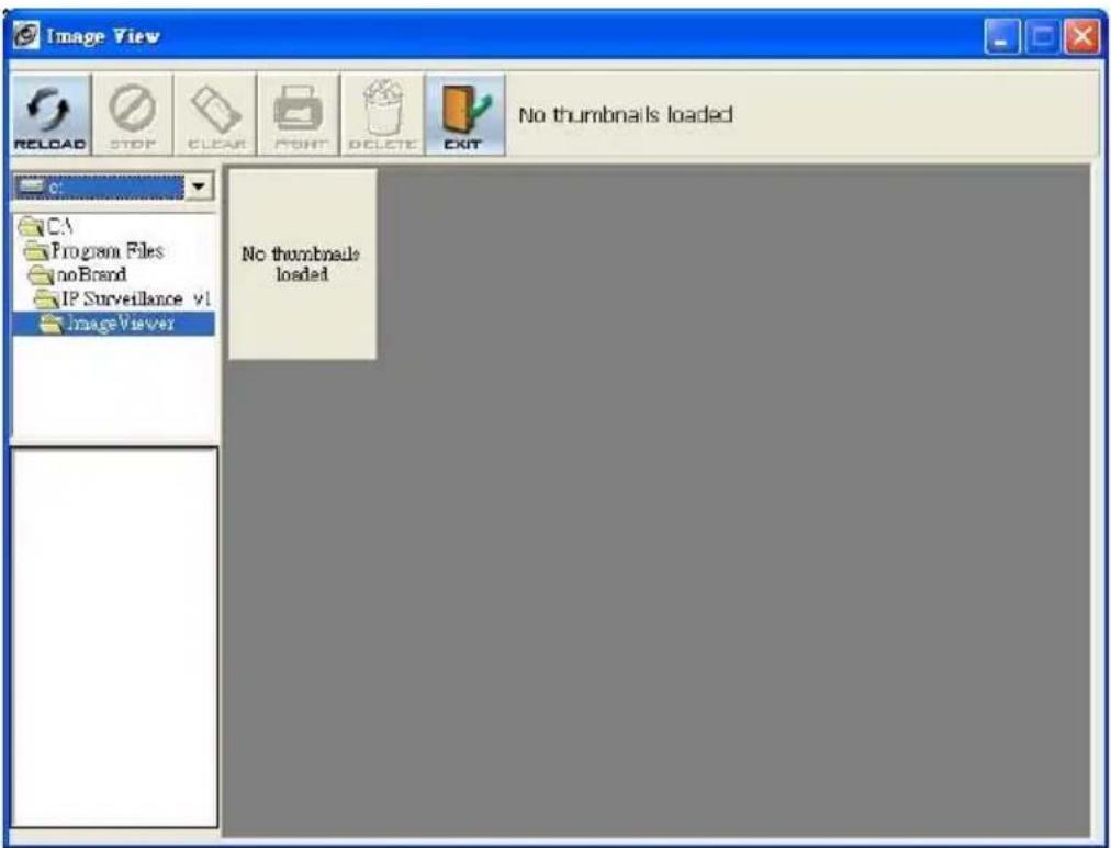
text_image
Image View RELOAD STOP CLEAR PRINT DELETE EXIT No thumbnails loaded C: CA Program Files noBrand IP Surveillance v1 ImageViewer No thumbnails loadedHow to view the live images of the IP camera via the Microsoft Internet Explorer on the Desktop PCs or the laptop computers in a situation where there are no monitors or television?
◇The way to get the IP address of the IP camera without a monitor:
There are three ways to get the IP address: Scan IP, UPnP and IP function.
Scan IP: Please refer to APPENDIX 1.
UPnP: Please refer to APPENDIX 2.
IP function: Please refer to APPENDIX 3.
Question 2:
How to set up the motion detection area and its sensitivity? How to record into the SD card for 30 seconds when the motion has been activated and use the Microsoft Internet Explorer to view the recorded files?
◇Set up the motion detection
-
Click the application button in the home page.
-
Click the Motion detection button on the left side of the page to enter the "ALARM – MOTION DETECTION" page.
-
Click and drag the mouse left button across a targeted zone to draw a red rectangle on the image. You can also draw the other targeted zones as you wish.
-
Please Enable the motion detection function.
-
Set up the sensitivity level from: Lowest, Low, Medium and High to Highest.
-
Click the Submit button to submit the setting.
Recording the images into an SD card while the motion detection function is working
-
Click the application button in the home page.
-
Click the Enable button below the ALARM item on the left side of the page to enter the "ALARM APPLICATION ENABLE SETTING" page.
-
Tick on "Enable ALARM-SAVE into SD Card" to activate it.
-
Click the Submit button to submit the setting.
◇Set the recording time (the AVI duration) of the SD card
- Click the Application button in the home page into the "SD-Card APPLICATION SETTING" page.
- Choose the AVI Duration from the drop-down list.
If you want to record the file into the SD card for 30 seconds, please choose 30 seconds. - Click the Submit button to submit the setting.
◇Use IE to view the recorded files
- Click the SD Card button in the home page to enter the page containing the "FILELIST of MEMORY CARD".
- Click the filename which you want to view.
- It will ask you to enter the username and password.
- If you didn't set the other player before, the AVI file will be played by the Windows Media Player.
Question 3:
How to use the DynDNS to connect the IP camera by using its Sub Hostname via the intranet?
◇Set the DDNS function
- Click the Network button in the home page.
- Click the DDNS button on the left side of the page to enter the "DDNS SETTING" page.
- Tick on the "Enable DDNS Function" to activate it.
- Choose one of the DDNS Types from the drop-down list.
If you didn't register for a DDNS before, please choose one of the DDNS Type then press "Apply" button to its registering homepage and register as a member. - Enter the DDNS Host Name, DDNS Account and DDNS Password which you created in the www.dyndns.com website.
- Click the Submit button to submit the setting.
NOTE: Please refer to the APPENDIX 4 for more details.
◇Set the PPPoE function
- Click the network button in the home page.
-
Click the PPPoE button on the left side of the page to enter the "PPPoE SETTING" page.
-
Choose "ON" from the "PPPoE mode" list to activate it.
- Enter the Account and the Password which are provided from your ISP.
- Click the Submit button to submit the setting.
NOTE: Please refer to section 5.1.8 for more details.
◇Use the Sub Hostname to view the IP camera
- Click the URL block at the top of the PC screen.
- Type in the DDNS Host Name of the IP camera into the URL block and press the "Enter" button to enter the login page.
- Enter the user name and fill in the password.
- Click the "OK" button and enter the home page of the IP camera.
Question 4:
How to add or modify the users and their authorities of using the IP camera?
◇Entering the setting page
- Click the system button in the home page.
- Click the Users button on the left side of the page to enter the "SYSTEM - USERS" page.
◇ Add a new user
-
Please enter the user name, the password, the confirmed password and choose the authority.
There are three different levels of authorities, namely Admin, Operator and Viewer.
Admin: The user who accesses with the admin name and password has the full power to even change the settings of the IP camera.
Operator: The suggested choice for normal use.
Viewer: The user who accesses with just the viewer name and password has only a limited power to view. -
Click the Submit button to submit the new user's setting.
◇Modify the user
- Click the user name you want to modify on the User List.
- Enter the password, the confirmed password and choose the authority.
- Click the Submit button to submit the new setting.
Delete a user
- Click the user name you want to modify on the User List.
-
Click the Delete button.
-
SPECIFICATIONS
| Model Number DDK-1500 | |||
| Video | Video sensor 1/3" Sony | Super HAD CCD (with HQ1 DSP) | |
| System | NTSC | ||
| Horizontal resolution 520 TV lines | |||
| Lens | C/CS | ||
| Auto Iris type DC-iris | |||
| Day and Night Mechanical IR Cut Filter: Auto; Color / Monochrome | |||
| AWB 2500°K ~ 9500°K | |||
| AES 1/60 ~ 1/100000 sec | |||
| High speed shutter 1/1000 sec | |||
| Min. illumination | Color 0.5 lux @ F1.2 | ||
| B/W 0.03 lux @ F1.2 | |||
| Image | Compression | MJPEG | |
| Resolution | 352 x 240720 x 480 (Frame)720 x 240720 x 480 (Filed) | Full D1VGAHalf VGAHalf D1CIFQVGA | |
| Frame-rate -- | 30 / 24 / 15 FPS | ||
| Picture size (quality) | 4~64KB | 64Kbps ~ 8Mbps (Bit rate) | |
| Configurations | Max AGC, Contrast, Brightness, WB, BLC, Sharpness,Saturation, Flickerless, Mask area | ||
| Motion detection Motion Detection (96 zones, 5 levels) | |||
| Audio | Built-in microphone | 8 kHz sample rate | |
| Network | Interface | Ethernet (RJ-45 wired, 10/100 base-tx), MDIX support | |
| Protocols | TCP/IP, DHCP, HTTP, ICMP, UPnP, ARP, DNS, DDNS, PPPoE | ||
| Throughput | 2.0M bytes/sec | ||
| Software | Web browser | Microsoft IE 6.0 or above | |
| PC | Free bundle PC software supports 32CH recording | ||
| Development tools | ActiveX / HTTP-API / SDK | ||
| Security | Multiple level / Multiple users / IP address filtering | ||
MPEG
| Connectors | Video output 1.0 Vpp, 75 ohm, composite, negative, BNC x 1 | |
| Alarm I/O 1 input / 1 output | ||
| Serial port RS-485 | ||
| SD card Alarm and Schedule recording / update | ||
| USB Configuration / Update | ||
| Reset | Factory | |
| Others | LED indicator Power / Network indicator | |
| Power requirement DC 12V / PoE | ||
| Operating Temperature 0°C ~ 50°C | ||
| Dimensions 60(W) x 45(H) x 94(D) mm | ||
| Approvals | FCC, | |
| Accessories | Power adapter x 1USB wire x 1User manual x 1PC software x 1 | |
CE,
*Specifications are subject to change without notice.
8. Functions of client PC
| System requirement Windows 2000, XP or above | |
| Browser | IE 6.x |
| Live Monitor Max. 16 Split , Real Time REC/ Capture/ Audio/ Live Event/ Full Screen | |
| Playback Viewer | Playback, Time / live event Search / Export (JPEG / AVI) |
| Settings | Device/ System/ Camera management/ web page |
| Multi-camera link | Max. 16 camera |
APPENDIX 1. -SCANIP
Follow the instructions below to use the SCANIP software to search the IP camera devices from a local location.
- Click the button to discover the connection of the all-type device in the LAN. The Device List will display the connection of the all-type device.
- Select the desired device from the Device List.
- Click the desired device to show the window while the IP camera information acts to display the desired changes instantly.
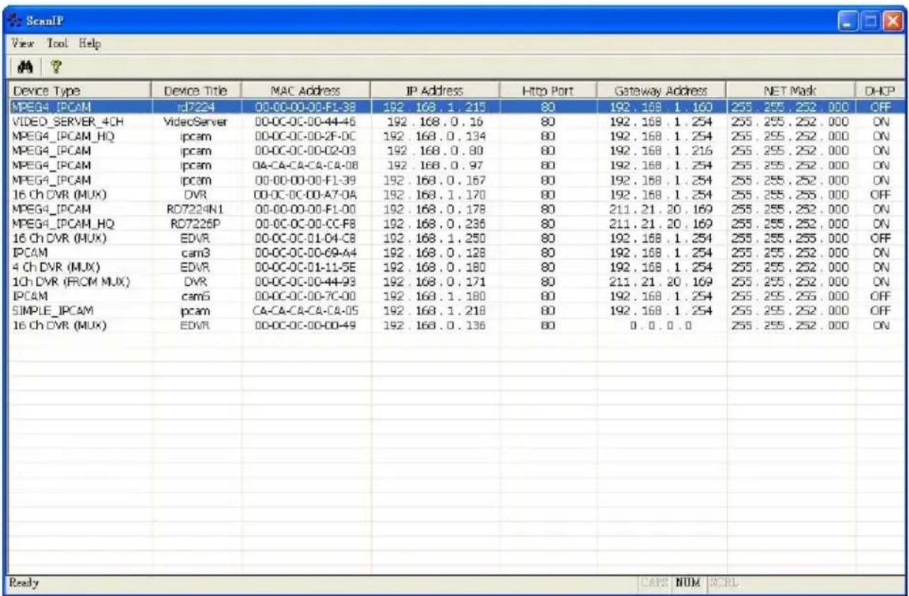
- Do you want to automatically search free IP?
If and when you want to automatically search the free IP, select "Yes" or "No". If you click "Yes" the software will provide the "Free IP Address" boxes on the right side of the window. If you click "No", these address boxes will not show.
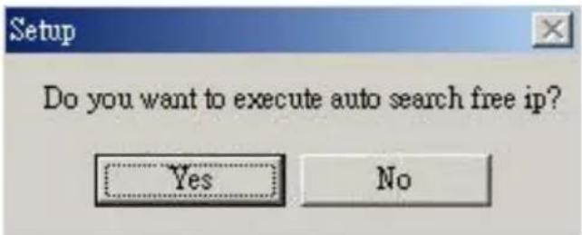
text_image
Setup Do you want to execute auto search free ip? Yes No- Manual insertion of "Free IP Address".
If you have clicked "No", please manually type in insertions as required in the "Free IP Address", "Gateway Address", and "NET Mask". Follow each insertion you make by typing in the "Login Name" and "Password", and click "UPDATE" to send your alterations to the IP camera.
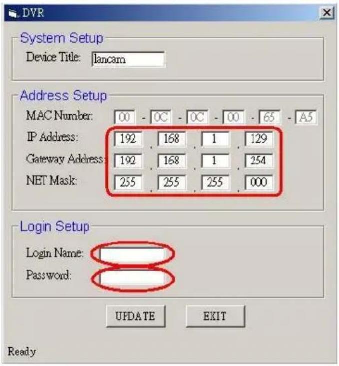
text_image
DVR System Setup Device Title: lancam Address Setup MAC Number: 00 - OC - OC - 00 - 65 - A5 IP Address: 192 168 1 129 Gateway Address: 192 168 1 254 NET Mask: 255 255 255 000 Login Setup Login Name: Password: UPDATE EXIT Ready- Automatically search "Free IP Address".
If you clicked "Yes" the "Free IP Address" box will appear on the right.
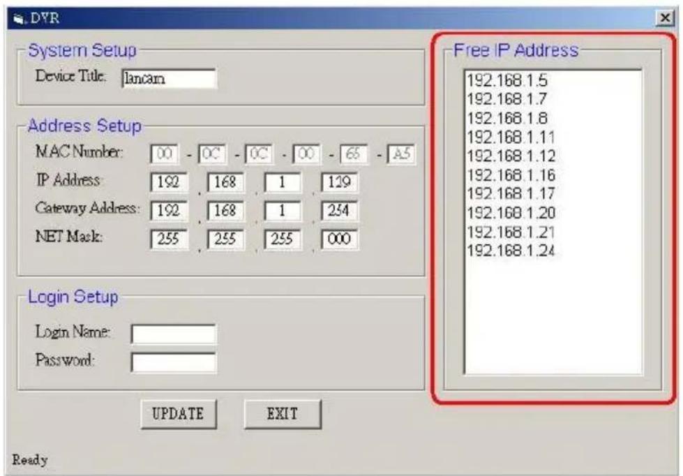
text_image
DVR System Setup Device Title: lancam Address Setup MAC Number: 00 - OC - OC - 00 - 65 - A5 IP Address: 192 168 1 129 Gateway Address: 192 168 1 254 NET Mask: 255 255 255 000 Login Setup Login Name: Password: UPDATE EXIT Ready Free IP Address 192.168.1.5 192.168.1.7 192.168.1.8 192.168.1.11 192.168.1.12 192.168.1.16 192.168.1.17 192.168.1.20 192.168.1.21 192.168.1.24- Select and double click any of the addresses in the "Free IP Address" box on the right to
enter it into an IP Address on the left.
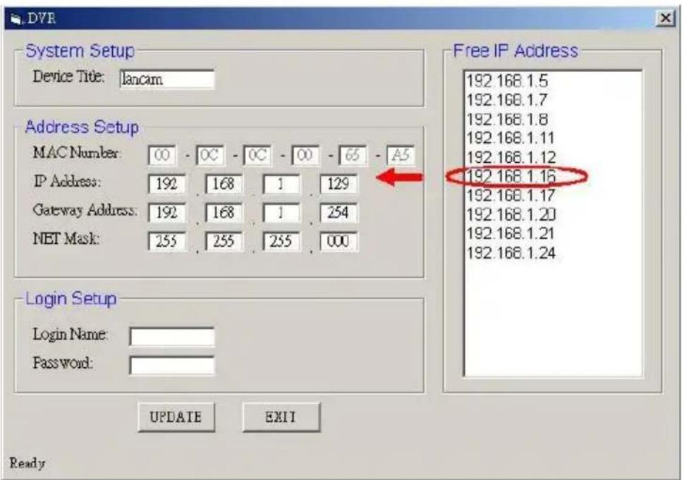
text_image
DVR System Setup Device Title: lancam Address Setup MAC Number: 00 - OC - OC - 00 - 65 - A5 IP Address: 192 168 1 129 Gateway Address: 192 168 1 254 NET Mask: 255 255 255 000 Login Setup Login Name: Password: UPDATE EXIT Ready Free IP Address 192.168.1.5 192.168.1.7 192.168.1.8 192.168.1.11 192.168.1.12 192.168.1.16 192.168.1.17 192.168.1.20 192.168.1.21 192.168.1.24- To change any IP address, type in the new address in the "Free IP Address" box on the right as well as the device "Login Name" and "Password" in their respective blanks at bottom left, then click "UPDATE", and the new address will automatically be sent to the device.
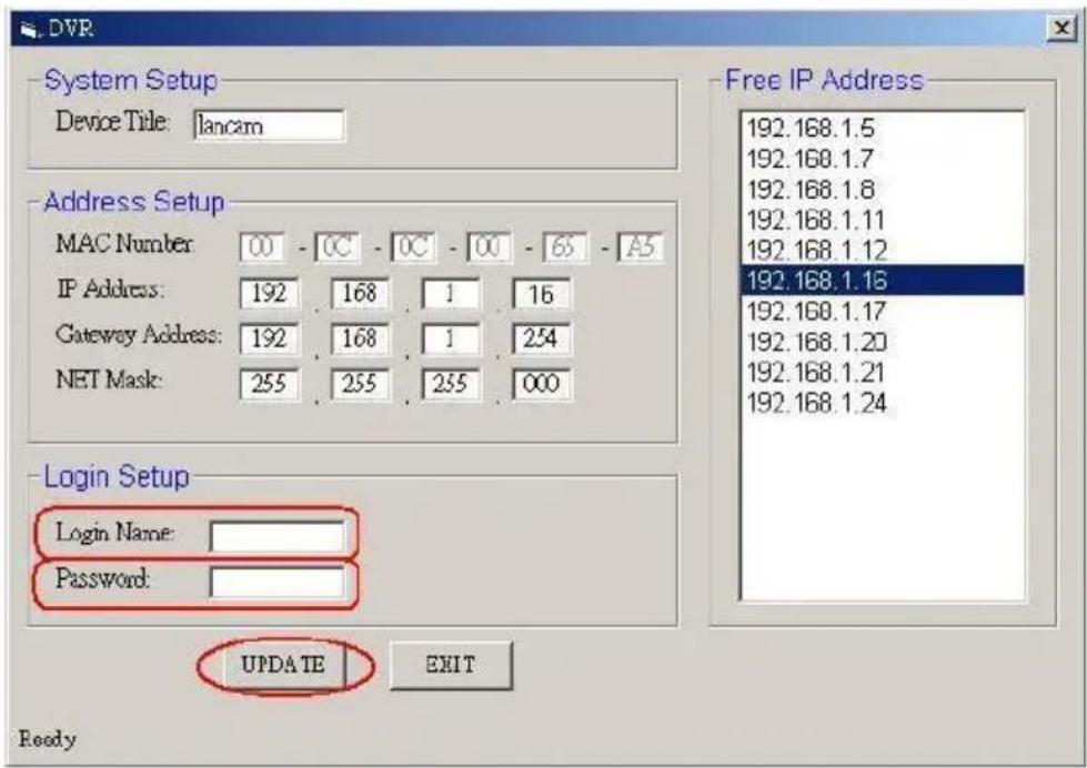
text_image
DVR System Setup Device Title: lancam Address Setup MAC Number: 00 - 0C - 0C - 00 - 65 - A5 IP Address: 192 168 1 16 Gateway Address: 192 168 1 254 NET Mask: 255 255 255 000 Login Setup Login Name: Password: UPDATE EXIT Ready Free IP Address 192.168.1.5 192.168.1.7 192.168.1.8 192.168.1.11 192.168.1.12 192.168.1.13 192.168.1.17 192.168.1.20 192.168.1.21 192.168.1.24 UPDATE EXIT- Click "Exit" at bottom right to shut the device.
APPENDIX 2. -IP camera UPnP How To
The most troublesome issue when you setup an ipxcam ^® is that you have no idea what the IP address of this device is. Now ipxcam ^® supports the UPnP (Universal Plug and Play) protocol which makes it easier for you to examine it; however, it is a pity that Microsoft Windows XP doesn't start this service by default. Therefore, the following procedures will help you to turn it on and discover your ipxcam ^® step by step as shown in Figure1 below.
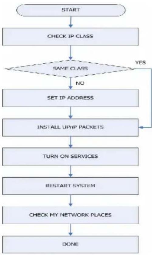
flowchart
graph TD
    A["START"] --> B["CHECK IP CLASS"]
    B --> C{SAME CLASS}
    C -->|NO| D["SET IP ADDRESS"]
    D --> E["INSTALL UP/HP PACKETS"]
    E --> F["TURN ON SERVICES"]
    F --> G["RESTART SYSTEM"]
    G --> H["CHECK MY NETWORK PLACES"]
    H --> I["DONE"]
    C -->|YES| J["End"]
Figure 1 UPnP Setup Flow Chart
1. Check the IP class of your PC
In most case Microsoft Windows XP ^ will assign an IP address, 169.254.*.*, automatically with a subnet mask, 255.255.0.0, if the DHCP server is absent, while the default IP address of an ipxcam ^ is 192.168.1.168 with a subnet mask of 255.255.255.0. There won't be any communication due to different IP class domains, and you have to modify the relative settings or the UPnP protocol won't work; however, checking your own IP address is necessary. Here are the procedures to check and modify them.
Step 1: From the Start menu, point to Settings, and then click Control Panel. See Figure 2.
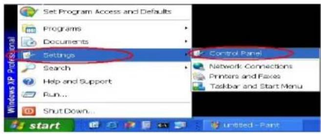
text_image
Set Program Access and Defaults Programs Documents Settings Search Help and Support Run... Shut Down... Control Panel Network Connections Printers and Faxes Taskbar and Start Menu startFigure 2
Step 2: When Control Panel appears, double-click the Network Connections icon. The Network Connections dialog box appears. See Figure 3.
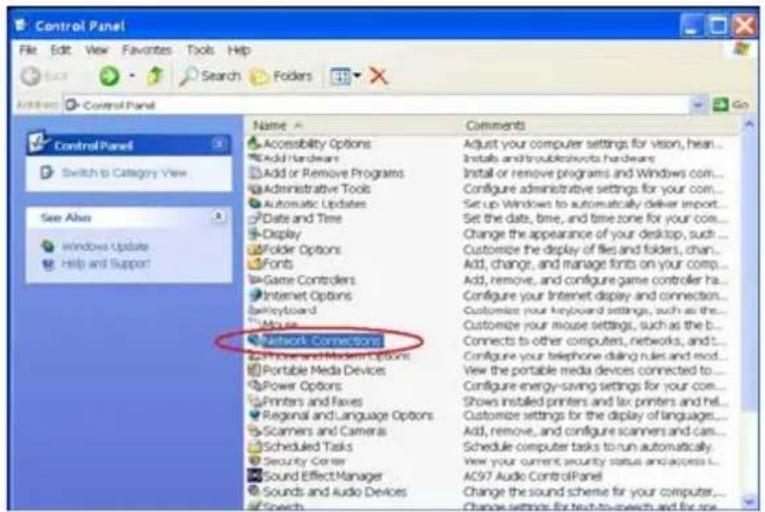
text_image
Control Panel File Edit View Favorites Tools Help Search Folders Address Control Panel Name Comments Accessibility Options Adjust your computer settings for vison, hear... Add or Remove Programs Install and trouble motors hardware Administrative Tools Install or remove programs and Windows com... Automatic Updates Configure administrative settings for your com... Date and Time Set up Windows to automatically deliver import... Display Set the date, time, and time zone for your core... Folder Options Change the appearance of your desktop, such ... Fonts Customize your display of files and folders, chan... Game Controllers Add, change, and manage fonts on your comp... Internet Options Configure your Internet display and connection... Keyboard Customize your keyboard settings, such as the ... Mouse Customize your mouse settings, such as the b... Network Connections Connects to other computers, networks, and ... Phone and Media Options Configure your telephone during rules and mod... Portable Media Devices View the portable media devices connected to... Power Options Configure energy-saving settings for your core... Printers and Felves Shows installed printers and fax printers and hel... Regional and Language Options Customize settings for the display of languages... Scammers and Cameras Add, remove, and configure scanners and can... Scheduled Tasks Schedule computer tasks to run automatically. Security Center View your current security status and access... Sound Effect Manager AC97 Audio Control Panel Sounds and Audio Devices Change the sound scheme for your computer... Speech Change settings for next-to-speech and for meFigure 3
Step 3: Click the Protocols tab in the Network Connections dialog box. See Figure 4.
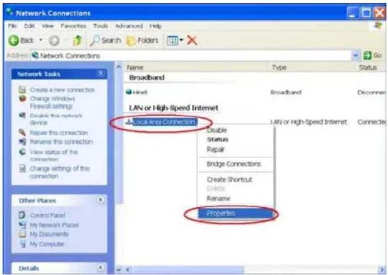
text_image
Network Connections File Edit View Favorites Tools Advanced Help Back Search Folders Address Network Connections Name Type Status Broadband Hnet Broadband Disconnect LAN or High-Speed Internet Local Area Connection LAN or High-Speed Internet Connecte Disable Status Repair Bridge Connections Create Shortcut Delete Rename Properties Other Places Control Panel My Network Places My Documents My Computer DetailsFigure 4
Step 4: When the Local Area Connection Properties dialog box shows up, choose Internet Protocol (TCP/IP) and click Properties. See Figure 5.
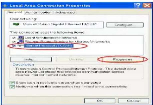
text_image
Local Area Connection Properties General Authorization Advanced Connect using: Marvell Yukon Gigabit Ethernet 10/1 10/1 Configure... This connection uses the following items. ✓ Client for Microsoft Networks ✓ File and Desktop Sharing for Microsoft Networks ✓ Internet Protocol (TCP/IP) Install Uninstall Properties Description Transmission Control Protocol/Internet Protocol: The default wide area network protocol that provides communication across diverse interconnected networks. ✓ Show icon in notification area when connected ✓ Notify me when this connection has limited or no connectivity OK CancelFigure 5
Step 5: In the Internet Protocol(TCP/IP) Properties dialog box, choose Use the following IP
Address to indicate that you do not wish to use DHCP, and assign IP Address
192.168.1.200 with Subnet mask 255.255.255.0.
Click OK when you finish it. See Figure 6.
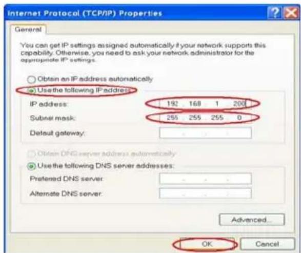
text_image
Internet Protocol (TCP/IP) Properties General You can get IP settings assigned automatically if your network supports this capability. Otherwise, you need to ask your network administrator for the appropriate IP settings. Obtain an IP address automatically Use the following IP address: IP address: 192 168 1 200 Subnet mask: 255 255 255 0 Detout gateway: Obtain DNS server addresses automatically Use the following DNS server addresses: Preferred DNS server: Alternate DNS server: Advanced... OK CancelFigure 6
Step 6: Choose Close to finish the modification. See Figure 7.
text_image
Local Area Connection Properties General Authentication Advanced Connect using: Marvell Yukon Gigabit Ethernet 10/100/1 Configure This connection uses the following items: Client for Microsoft Networks File and Printer Sharing for Microsoft Networks Internet Protocol (TCP/IP) Install... Unsett Properties Description Transmission Control Protocol/Internet Protocol. The default wide area network protocol that provides communication across diverse interconnected networks. Show icon in notification area when connected Notify me when this connection has limited or no connectivity Close CancelFigure7
2. Install UPnP Packets
As described before, Microsoft Windows XP ^® doesn't start the UPnP service by default; however, we have to install some packets before we initialize it. The following steps will help you to install them.
Step1: From the Start menu, point to Set Program Access and Default, and then click it. See
Figure 8
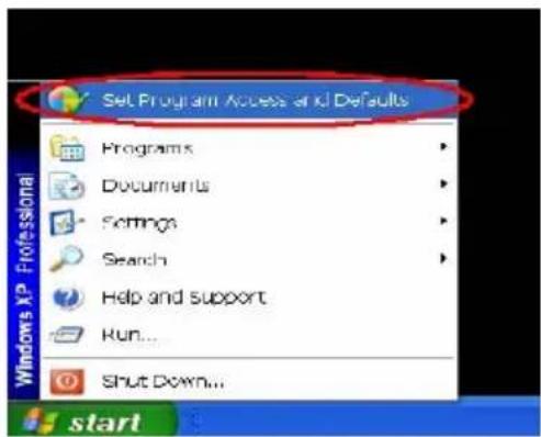
text_image
Set Program Access and Defaults Programs Documents Settings Search Help and Support Run... Shut Down...Figure 8
Step 2: When the Add or Remove Programs dialog box appears, click the Add/Remove Windows Components button. See Figure 9.
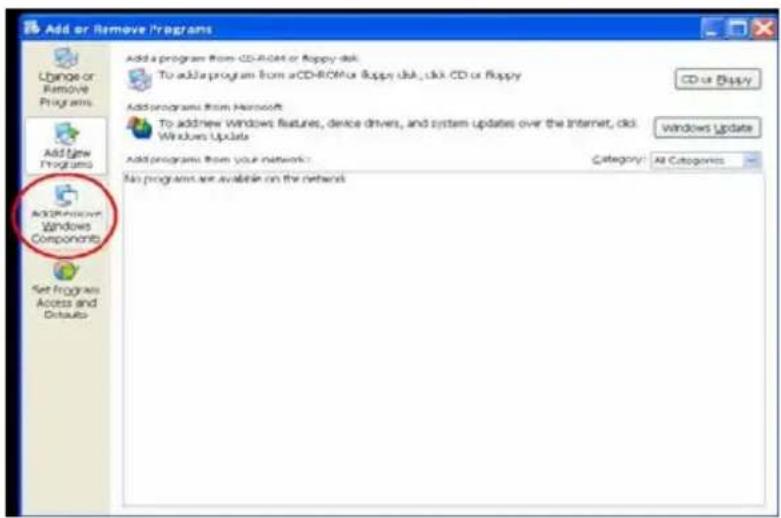
text_image
Add or Remove Programs Add a program from CD-ROM or floppy disk. To add a program from aCD-ROM or floppy disk, click CD or floppy CD or Bipy Add programs from Microsoft To add new Windows features, device drivers, and system updates over the Internet, click Windows Update Windows Update Add programs from your network: Category: All Categories No programs are available on the network.Figure 9
Step 3: Check the Network Services in the Windows Component Wizard dialog box, and then click Details.... See Figure10.
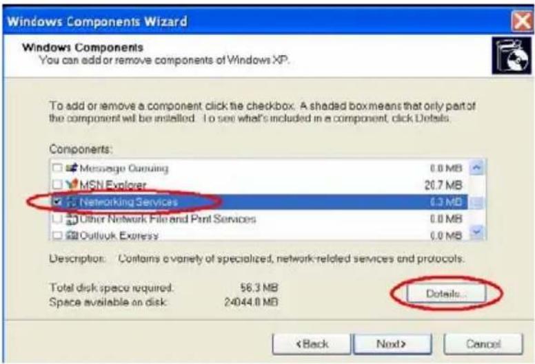
text_image
Windows Components Wizard Windows Components You can add or remove components of Windows XP. To add or remove a component click the checkbox. A shaded box means that only part of the component will be installed. To see what's included in a component, click Details. Components: Message Consulting 0.0 MB MSN Explorer 20.7 MB Networking Services 0.3 MB Other Network File and Port Services 0.0 MB Outlook Express 0.0 MB Description: Contains a variety of specialized, network-related services and protocols. Total disk space required 56.3 MB Space available on disk 24044.0 MB Details... < Back Next> CancelFigure 10
Step 4: Check UPnP User Interface, and choose OK. See Figure 11.
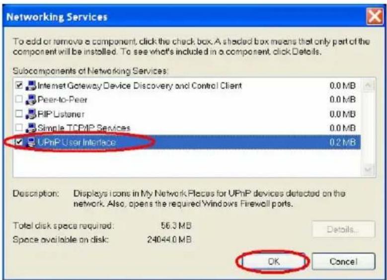
text_image
Networking Services To add or remove a component, click the check box. A shaded box means that only part of the component will be installed. To see what's included in a component, click Details. Subcomponents of Networking Services: Internet Gateway Device Discovery and Control Client 0.0 MB Peer-to-Peer 0.0 MB RIP Listener 0.0 MB Simple TCP/IP Services 0.0 MB UPnP User Interface 0.2 MB Description: Displays icons in My Network Places for UPnP devices detected on the network. Also, opens the required Windows Firewall ports. Total disk space required: 56.3 MB Space available on disk: 24044.0 MB Details... OK CancelFigure 11
Step 5: When the original Network Component Wizard dialog box returns, click Next. See Figure12.
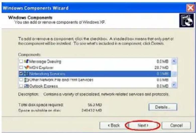
text_image
Windows Components Wizard Windows Components You can add or remove components of Windows XP. To add or remove a component, click the checkbox. A shaded box means that only part of the component will be installed. To see what's included in a component, click Details. Components: Message Queuing 0.0 MB MSN Explorer 20.7 MB Networking Services 0.3 MB Other Network File and Print Services 0.0 MB Outlook Express 0.0 MB Description: Contains a variety of specialized, network-related services and protocols. Total disk space required: 56.3 MB Space available on disk: 240432 MB Details... < Back Next > CancelFigure 12
Step 6: After about one minute the UPnP installation will be done, and choose Finish to close it. See Figure13.
text_image
Windows Components Wizard Completing the Windows Components Wizard You have successfully completed the Windows Components Wizard. To close this wizard, click Finish.Figure 13
3. Turn on Services
After installation, we should turn on the relative services to start the UPnP protocol. The following procedures will teach you how to do it.
Step 1: From the Start menu, point to Settings, and then click Control Panel. See Figure14.
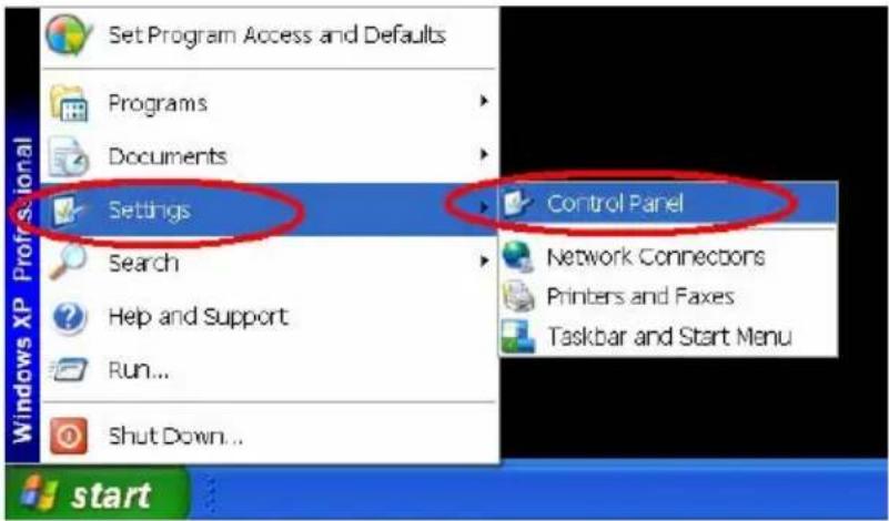
text_image
Set Program Access and Defaults Programs Documents Settings Search Help and Support Run... Shut Down... Control Panel Network Connectors Printers and Faxes Taskbar and Start Menu startFigure 14
Step 2: When Control Panel appears, double-click the Administrative Tools icon. The Administrative Tools dialog box appears. See Figure15.
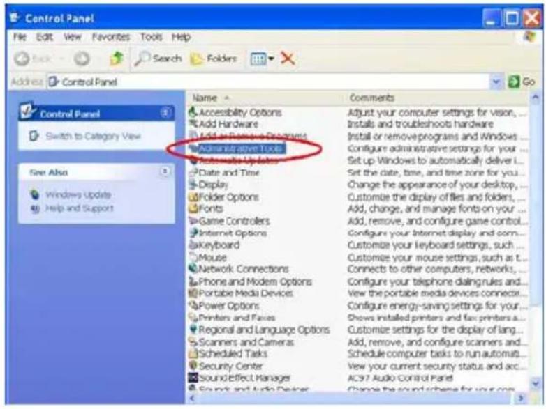
text_image
Control Panel File Edit View Favorites Tools Help Search Folders Address Control Panel Name Comments Accessibility Options Adjust your computer settings for vision... Add Hardware Installs and troubleshoots hardware Add or Remove Programs Install or remove programs and Windows... Administrative Tools Configure administrative settings for your... Automobile Update Set up Windows to automatically deliver ... Date and Time Set the date, time, and time zone for you... Display Customize the display of files and folders... Folder Options Customize your keyboard settings, such... Fonts Customize your mouse settings, such as t... Game Controllers Customize your mouse settings, such as t... Internet Options Customize your keyboard settings, such... Keyboard Customize your keyboard settings, such... Mouse Customize your keyboard settings, such as t... Network Connections Customize your mouse settings, such as t... Phone and Modem Options Customize your keyboard settings, such as t... Portable Media Devices Customize your keyboard settings, such as t... Power Options Customize your keyboard settings, such as t... Printers and Faces Customize your keyboard settings, such as t... Regional and Language Options Customize your keyboard settings, such as t... Scanners and Cameras Customize your keyboard settings, such as t... Scheduled Tasks Customize your keyboard settings, such as t... Security Center Customize your keyboard settings, such as t... Sound Effect Manager Customize your keyboard settings, such as t... Sound and Audio Devices Customize your keyboard settings, such as t... Comments Close the sound scheme for your comFigure15
Step 3: Click the Services icon in the Administrative Tools dialog box. See Figure16.
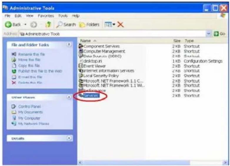
text_image
Administrative Tools File Edit View Favorites Tools Help Back Search Folders Administrative Tools File and Folder Tasks Rename this file Move the file Copy this file Publish this file to the Web Email this file Delete this file Name Size Type Component Services 2 KB Shortcut Computer Management 2 KB Shortcut Data Sources (OBEC) 2 KB Shortcut desktop.ini 1 KB Configuration Settings Event Viewer 2 KB Shortcut Internet information Services 2 KB Shortcut Local Security Policy 2 KB Shortcut Microsoft NET Framework 1.1 C... 2 KB Shortcut Microsoft NET Framework 1.1 W... 2 KB Shortcut Performance 2 KB Shortcut Services 2 KB Shortcut Other Names Control Panel My Documents My Computer My Network Places DetailsFigure16
Step 4: When the Services dialog box shows up, double click the SSDP Discovery Service icon. See Figure17.
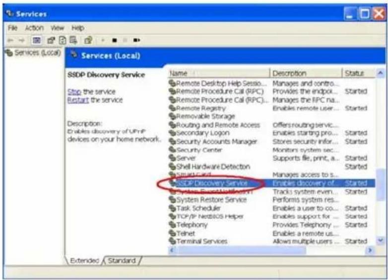
text_image
Services File Action View Help Services (Local) Services (Local) SSDP Discovery Service Stop the service Restart the service Description: Enables discovery of UPnP devices on your home network... Name Description Status Remote Desktop Help Sesso... Manages and contro... Remote Procedure Call (RPC) Provides the endpoint... Started Remote Procedure Call (RPC)... Manages the RPC na... Remote Registry Enables remote user... Started Removable Storage Routing and Remote Access Offers routing service... Secondary Logon Enables starting pro... Started Security Accounts Manager Stores security info... Started Security Center Monitors system sec... Server Supports file, print, a... Started Shell Hardware Detection Started Struct Card Manages access to s... SSDP Discovery Service Enables discovery of... Started System Store/Workbench Tracks system even... Started System Restore Service Performs system res... Task Scheduler Enables a user to co... Started TCP/IP NettBOS Helper Enables support for ... Started Telephony Provides Telephony ... Started Telnet Enables a remote us... Started Terminal Services Allows multiple users ... Started Extended StandardFigure17
Step 5: Choose Automatic in the Startup type, and click OK to start it. See Figure18.
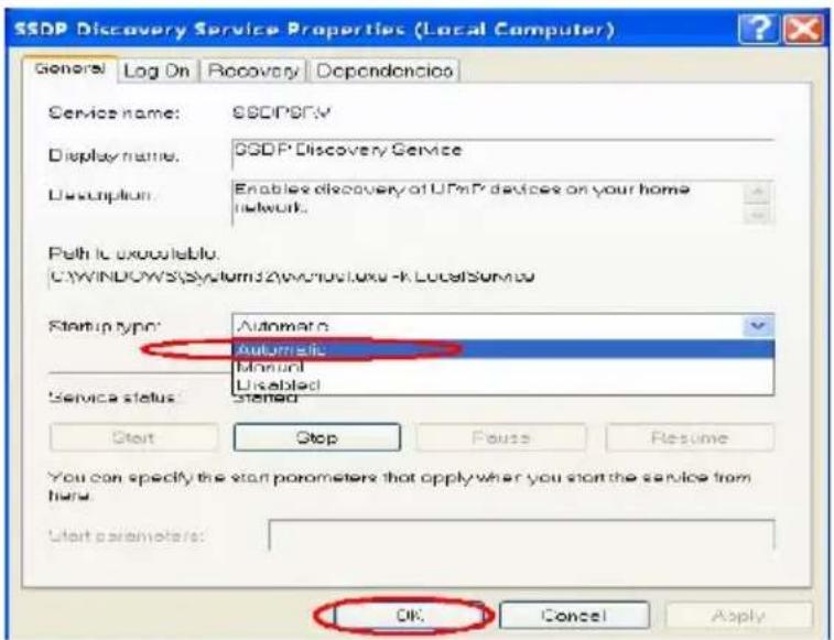
text_image
SSDP Discovery Service Properties (Local Computer) General Log On Recovery Dependencies Service name: SSDP09V Display name: SSDP Discovery Service Description: Enables discovery of UPnP devices on your home network. Path to available. C:\WINDOWS\System32\wcr\u01d\u01d-xk\LocalService\ Startup type: Automatic Automatic Manual Disabled Service status: Stensed Start Stop Pause Resume You can specify the start parameters that apply when you start the service from hand. User parameters: OK Cancel ApplyFigure18
Step 6: When the Services dialog box appears again, double click the Universal Plug and Play Device Host icon. See Figure19.
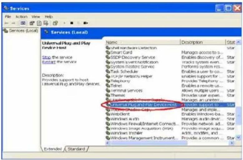
text_image
Services File Action View Help Services (Local) Services (Local) Name Description Stat Unwall Hardware Detection Star Smart Card Manages access to ... SSDP Discovery Service Enables discovery of... Star System Event Notification tracks system even... Star System Restore Service Performed system rcs... Task Schedules Enables a user to co... Star ICU/IR Networks Helper Enables support for... Star Telephony Provides Telephony ... Star Telnet Enables a remote us... Terminal Services Allows multiple users ... Star Themes Provides user expert... Star Lackboxable Power Capsets Manages an uniter... Universal Plug and Play Device Host Provides support to... Star Volume Shadow Copy Manages and ample... WebClient Enables Windows-ba... Star Windows Auto Manages audio devic... Star Windows Firewall/Internet Connect... Provides network ad... Star Windows Image Acquisition (WTA) Provides image acqui... Star Windows Installer Addt, modifiers, and ... Windows Management Instrument... Provides a common ... Star Extended StandardFigure19
Step 7: Choose Automatic in the Startup type, press the Start button, and click OK to start it. See Figure20.
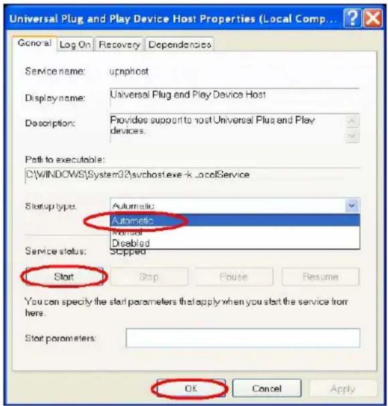
text_image
Universal Plug and Play Device Host Properties (Local Comp... General Log On Recovery Dependencies Service name: upnphost Display name: Universal Plug and Play Device Host Description: Provides support to host Universal Plug and Play devices. Path to executable: C:\WINDOWS\System32\svchost.exe-k _localService Startup type: Automatic Automatic Manual Disabled Service status: Sipped Start Stop Fouse Resume You can specify the start parameters that apply when you start the service from here. Start parameters: OK Cancel ApplyFigure20
Step 8: Restart your system.
4. Scan ipxcams ^® through My Network Place
After your installation and starting services, the UPnP protocol will take effect. You can scan all ipxcams ^® in My Network Place like Figure21 and Figure22 below.
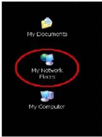
text_image
My Documents My Network Places My ComputerFigure21
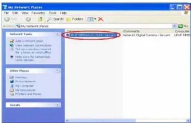
text_image
My Network Places File Edit View Favorites Tools Help Search Folders My Network Places Network Tasks Add a network prior View network connections Find up a network connection for a phone or email office Hide store for networked order details Other Places Desktops Project network My Computer My Documents Printers and Files Details URL IP 140004.00-2234 - Secured Connections Network Digital Camera - Secured Computer URL IP MPDFigure22
Just double click the UPnP MPEG4 IP camera the video live stream will pop up automatically without assigning any IP address in Microsoft Internet Explorer.
APPENDIX 3. –The ARP function
Setting the IP Address
The Ethernet interface on the ipxcam has a default IP address (192.168.1.168) that most likely needs to be changed to make it work on your local network. You need to acquire a unique IP address (ask your network administrator). For the initial setting of the IP address the ipxcam needs to be connected to the same network segment as your client, and the IP address can then be configured by using a combination of ARP and ping command.
Use any of the following ways to set the IP address within thirty seconds after booting the ipxcam (re-cycle the power). Setting IP using the method below can only be done on the Ethernet interface.
ARP and ping from Windows or MS-DOS:
The user can open the PC's MS-DOS windows from the WINDOWS 98 operation system, or open the PC's Command Prompt windows from either the WINDOWS 2000 or the WINDOWS XP operation system.
- Start a DOS prompt window
- Type the following in 30 seconds after the booting:
arp -s <IP address> <Ethernet address>
[or arp -s <IP address> <MAC address>]
ping <IP address>
Example:
arp -s 192.168.1.100 00-0C-0C-00-00-01
ping 192.168.1.100
The IP address now is: 192.168.1.100.
ARP and ping from UNIX or GNU/Linux:
- Start a shell
- Type the following as superuser (root):
arp -s
[or arp -s
ping
Example:
arp -s 192.168.1.100 00-0C-0C-00-00-01
ping 192.168.1.100
The device responds to the ping in the examples above if the new address was configured. Note, this method will set the IP address permanently.
Note: The default account and password after the reset are root and Admin.
APPENDIX 4. –Register as a DDNS member
The DDNS (dynamic domain name system) is a function which is provided by an American company. Please refer to www.dyndns.com. This chapter provides the user with the basic instructions on how to register a free DDNS service.
Registering for a DDNS
Enter the URL www.dyndns.com. In the upper right-hand corner of the main page, where there is an item, "Create Account", as shown in Figure 1.
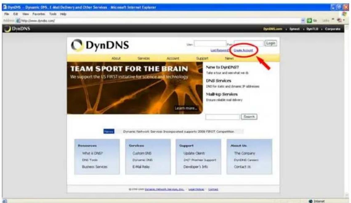
text_image
DynDNS DynDNS DynDNS.com Dynest DynTLS Corporate Last Resource Custom Account About Services Account Support News TEAM SPORT FOR THE BRAIN We support the US FIRST initiative for science and technology New to DynDNS7 Take a tour and see what we do DNS Services DNS for static and dynamic 3P addresses MailHop Services Ensure reliable real delivery Learn more... Search Notes Dynamic Network Service Incorporated supports 2008 FIRST Competition Resources What is DNS? DNS Tools Business Services Services Custom DNS Dynamic DNS E-Mail Relay Support Update Clients 24/1 Premier Support Developer's Info About Us. The Company DynDNS Careers Contact Us © 2008 DynDNS Network Services Inc. - legal Office - ContactFigure 1
Create an account
After clicking "Create Account", you will enter the Create Account page. Please complete the form at the bottom of the page to create your account. You will receive an e-mail containing instructions to activate your account. If you do not follow the directions within 48 hours, you will need to recreate your account.
Set up the DDNS
After creating the account successfully, please enter your user name and password in the upper right-hand corner of the main page to login, as shown in Figure 2.
After you login successfully, a text will appear saying "My Services", as shown in Figure 3.
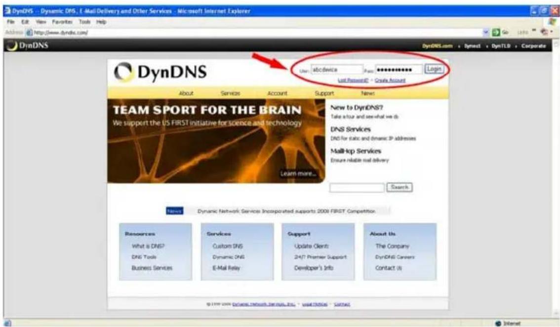
text_image
DynDNS DynDNS DynDNS.com - Dynact + DynTLD + Corporate User: a@device Pass: ********* Login Last Password: © Create Account About Services Account Support News TEAM SPORT FOR THE BRAIN We support the US FIRST initiative for science and technology New to DynDNS? Take a tour and see what we do DNS Services DNS for static and dynamic IP addresses Mail-top Services Ensure reliable real delivery Learn more... Search Notes Dynamic Network Services Incorporated supports 2008 FIRST Competition Resources What is DNS? DNS Tools Business Services Services Custom DNS Dynamic DNS E-Mail Relay Support Update Clients 24/7 Premier Support Developer's Info About Us The Company DynDNS Careers Contact Us © 2008 Dynast Research Services Inc. www.dynds.com / ContactFigure 2
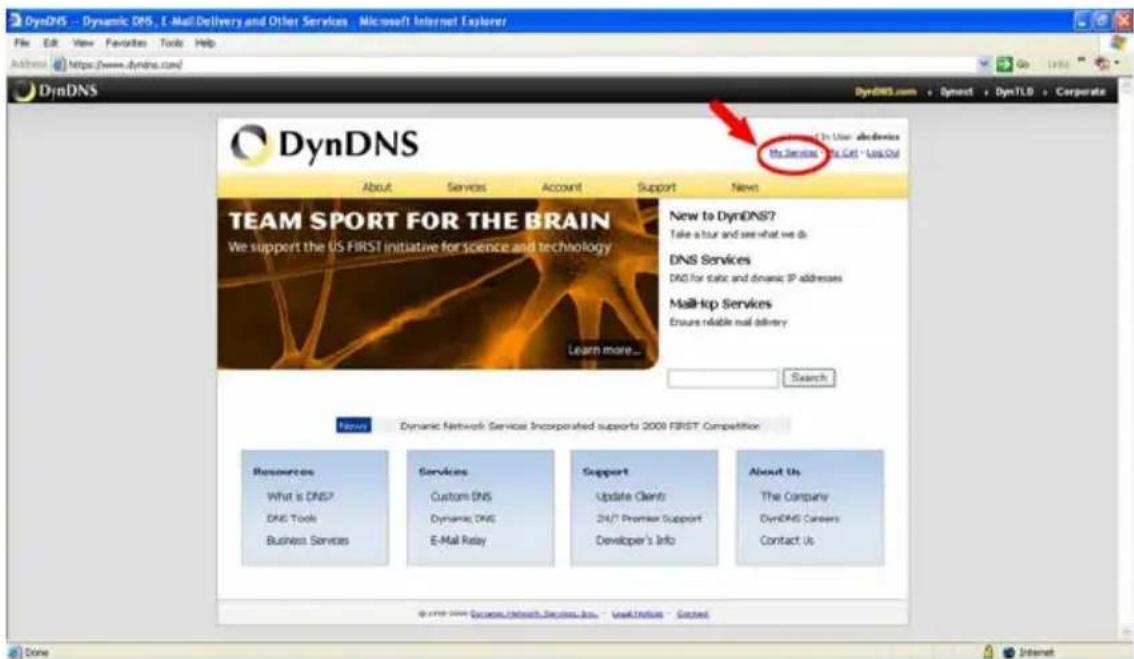
text_image
DynDNS DynDNS DynDNS.com - Dynost + DynTLD + Corporate DynDNS DynDNS About Services Account Support News TEAM SPORT FOR THE BRAIN We support the US FIRST initiative for science and technology New to DynDNS? Take a tour and see what we do DNS Services DNS for static and dynamic IP addresses Mail-lop Services Ensures reliable mail delivery Learn more... Search New Dynamic Network Service Incorporated supports 2008 FIRST Competition Resources Services Support About Us What is DNS? Custom DNS Update Clients The Company DNS Tools Dynamic DNS 24/7 Premier Support DynDNS Careers Business Services E-Mail Relay Developer's Info Contact Us © www.dynDNS.com - UserDirect - SlectedFigure 3
Click "My Services" to enter the service page. Please click the "Add Host Service" item which is below the "My Hosts" item, as shown in Figure 4.
Click “Add Host Service”, and its service items will appear. The Add Dynamic DNS Host item helps to add a new DDNS. Each member may have only one free account, and one free account can have only five DDNS.
Click Add Dynamic DNS Host to enter the DDNS setting page as shown in Figure 5.
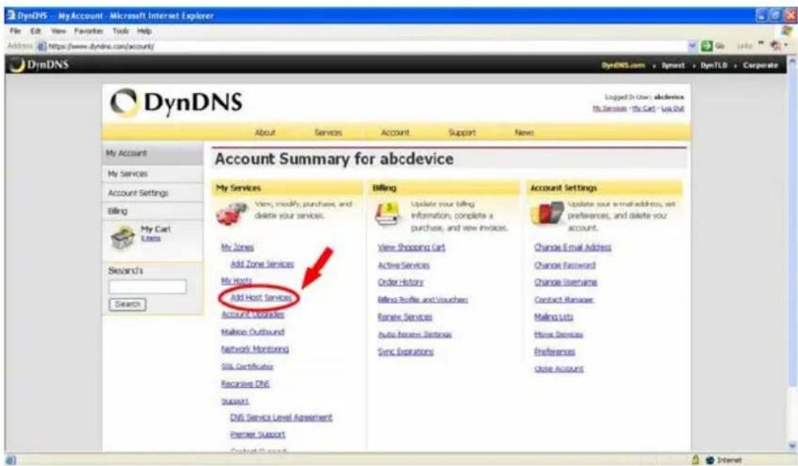
text_image
DynDNS DyndNS About Services Account Support News My Account My Services Account Settings Billing My Cart Users Search Search Account Summary for abcdevice My Services View, modify, purchases, and delete your services. My Zones Add Zone Services My Hosts Add Host Services Account Updates Mailbox Outbound Network Monitoring SIL Certificates Recessive DNS Support DNS Service Level Agreement Partner Support Billing Update your billing information, complete a purchase, and view invoices. View Shopping Cart Active Services Order History Billing Profile and Vouches Review Services Audio Services Sectiona Sync Expirations Account Settings Update your email address, exit preferences, and delete your account. Change Email Address Change Password Change Username Contact Manager Mailing Lists Time Services Preferences Close AccountFigure 4
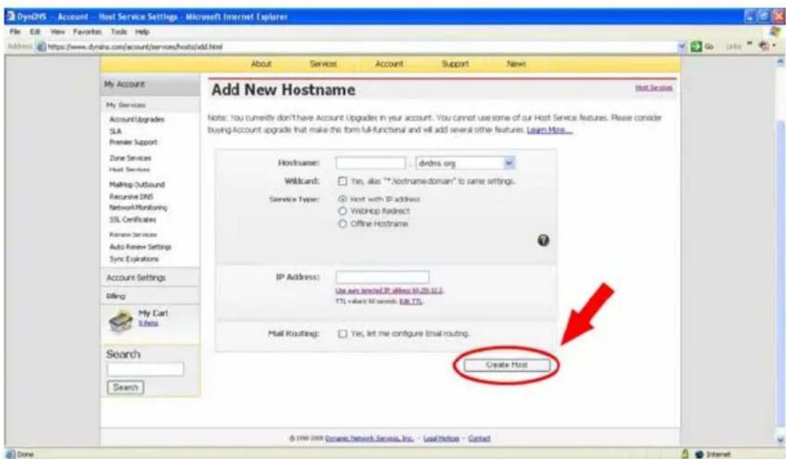
text_image
DynCHS - Account - Host Service Settings - Microsoft Internet Explorer File Edit View Favorites Tools Help Address https://www.dynch.com/account/services/hosts/add.html About Services Account Support News Add New Hostname Note: You currently don't have Account Upgrades in your account. You cannot use some of our Host Service features. Please consider buying Account upgrade that make the form full-functional and will add several other features. Learn More... HostName: dvdxns.org Wildcard: Yes, alias "altname-domain" to same settings. Service Type: Host with IP address WebHoop Redirect Offline Hostname IP Address: Use auto selected IP address 60.25.12.3 TTL value is 50 search. Edit TTS. Mail Routing: Yes, let me configure Email routing. Create Host My Account My Services AccountUpgrades SLA Premier Support Zone Services Host Services MailHop-Outbound Recursive DNS NetworkMonitoring SSL Certificates Rename Services Auto Review Settings Sync Options Account Settings Billing My Cart Tools Search Search © Dini.com Cownes Network Services, Inc. - Localotion - ContactFigure 5
All we have to set in this page is the "Hostname" item. The user can choose a SubHostname as s/he likes from the right-hand side of theHostname's drop-down list.
NOTE: You don't have to set the "IP Address" in the same format as the camera's IP Address. It will renew the IP Address automatically.
After finishing the setting, please press the "Create Host" button as shown in Figure 5.
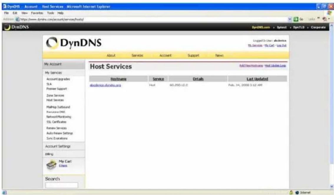
text_image
DynDNS - Account - Host Services - Microsoft Internet Explorer File Edit View Favorites Tools Help Address https://www.dynns.com/account/services/hosts/ DynDNS DynDNS Logged In User / abdevics My Service "To Call - Log Out" About Services Account Support News Host Services Add New Hosts - Host Update Loss Hostname Service Details Last Updated abdevics.dynns.org Host 60.250.12.2 Feb. 14, 2009 3:12 AM My Cart Etnes SearchFigure 6
APPENDIX 5. -MPEG4 Bit Rate Lookup Table of IP camera
- When frame rate is higher than 15 frames/second (15 is not including):
| Highest | High | Medium | Low | Lowest | ||||
| FULL D1 | 3 | 2.5 | 2 | 1.5 | 1 | |||
| VGA | 2.63 | 2.25 | 1.75 | 1.31 | 0.88 | |||
| Half D1 | 1.5 | 1.25 | 1 | 0.75 | 0.5 | |||
| Half VGA | 1.31 | 1.13 | 0.88 | 0.67 | 0.44 | |||
| CIF | 0.75 | 0.63 | 0.5 | 0.38 | 0.25 | |||
| QVGA | 0.66 | 0.56 | 0.44 | 0.38 | 0.22 | |||
| ZOOM * 2 | 3 | 2.5 | 2 | 1.5 | 1 | |||
| ZOOM * 3 | 3 | 2.5 | 2 | 1.5 | 1 | |||
| ZOOM * 4 | 3 | 2.5 | 2 | 1.5 | 1 | |||
- When frame rate is lower or equal to 15 frames/second:
| Highest | High | Medium | Low | Lowest | ||
| FULL D1 | 2.25 | 1.94 | 1.5 | 1.13 | 0.75 | |
| VGA | 1.94 | 1.69 | 1.31 | 0.98 | 0.66 | |
| Half D1 | 1.13 | 0.94 | 0.75 | 0.56 | 0.38 | |
| Half VGA | 0.98 | 0.84 | 0.66 | 0.49 | 0.33 | |
| CIF | 0.56 | 0.47 | 0.44 | 0.28 | 0.19 | |
| QVGA | 0.5 | 0.44 | 0.34 | 0.25 | 0.19 | |
| ZOOM * 2 | 2.25 | 1.88 | 1.5 | 1.125 | 0.75 | |
| ZOOM * 3 | 2.25 | 1.88 | 1.5 | 1.125 | 0.75 | |
| ZOOM * 4 | 2.25 | 1.88 | 1.5 | 1.125 | 0.75 | |
*The unit is in Mbps/second.
APPENDIX 6. -FAQ
- How to disable the DHCP function and use a static IP instead?
A : Turn up the "DIP SWITCH" from "3" to "4" and change the relative network settings, the IP Address, NetMask and Gateway on the image web page.
- Can the SD card be removed during recording?
A : No, it cannot be removed until the recording comes to a single point. The POWER LED flashing light signals the SD card is operating. The green light indicates the unit is activating. The red light warns the SD card cannot be removed. If the SD card is withdrawn in this mode, the card will break.
- I've set the function of "Motion Detection" but it doesn't seem to work.
A : Check if “Motion range” and “Sensitivity” have been set before activating the function.
- My AVI files recorded in the SD card cannot be displayed. What can I do to display the files?
A : Please visit "http://www.morgan-multimedia.com/" to download "Morgan M-JPEG codec" and install it, and then check the selection of the "IJP Core".
- How to turn on/off the OSD (on screen display) on/off on the IP camera?
A : Visit the homepage - tailpage.htm of the device, and select "ON" or "OFF" in the OSD column.
Example: suppose the IP address of the device is 192.168.1.168
Type in http://192.168.1.168/tailpage.htm (a registration is needed) and select "ON" or "OFF" in the OSD column.
WARNING: Please write down the IP address of the device before you turn off the OSD.