EDN3160 - Security Camera EverFocus - Free user manual and instructions
Find the device manual for free EDN3160 EverFocus in PDF.


User questions about EDN3160 EverFocus
0 question about this device. Answer the ones you know or ask your own.
Ask a new question about this device
Download the instructions for your Security Camera in PDF format for free! Find your manual EDN3160 - EverFocus and take your electronic device back in hand. On this page are published all the documents necessary for the use of your device. EDN3160 by EverFocus.
USER MANUAL EDN3160 EverFocus
Indoor IP Dome Camera
Quick Installation Guide
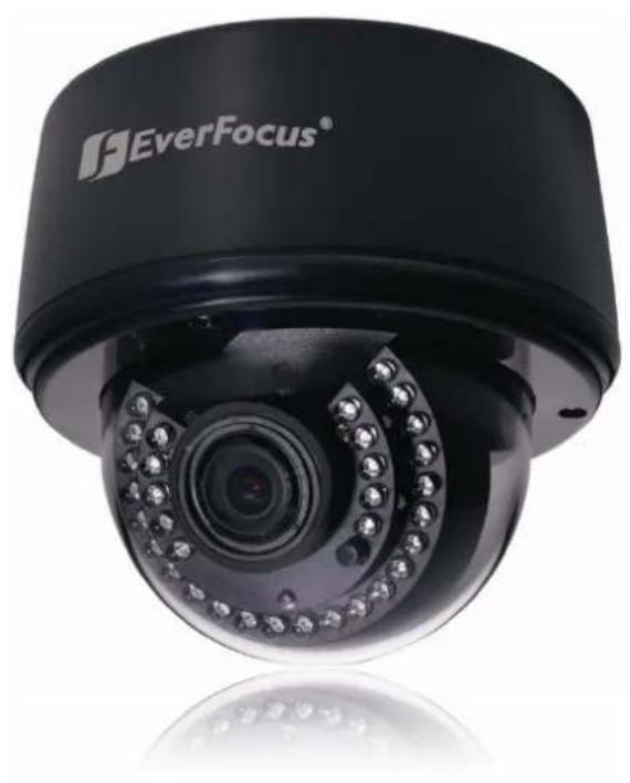
natural_image
Exterior view of a black EverFocus surveillance camera with embedded camera lens (no text or symbols on body)
Copyright © EverFocus Electronics Corp,
Release Date: October, 2012
1. Overview
The EDN Plus series IP dome is designed for indoor use. The series comes in three models: EDN3160 Plus / 3260 Plus / 3340 Plus.
| Model Name | Megapixel | P-Iris | WDR |
| EDN3160 Plus | 1.3 MP | Yes | Yes |
| EDN3260 Plus | 2 MP | Yes | Yes |
| EDN3340 Plus | 3 MP | Yes | No |
text_image
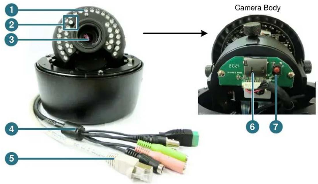
1 2 3 Camera Body 2021 6 7 4 5| No. | Item Name Descriptions | |
| 1 | IR LEDs | 33 IR LEDs for infrared illumination in night vision applications. |
| 2 | Light Sensor | Detects lights. |
| 3 Lens | Varifocal lens with P-Iris control. | |
| 4 5-Pin Data Cable | Provides connections for power, TV-out, video input / output and alarm input / output. See 5-Pin Data Cable later in this Quick Installation guide. | |
| 5 LAN / PoE Cable | Connects to a 10/100 Ethernet or PoE. | |
| 6 | Micro SD / SDHC Slot | For inserting a micro SD / SDHC card. |
| 7 | Reset Button | Resets all configurations to the factory default settings. |
System Requirement
Before installing, please check that your computer meets this system requirement.
- Operating System: Microsoft Windows XP / Vista (32-bit) / 7 (32-bit)
• Microsoft Internet Explorer 7 or above
Packing List
• EDN Plus Series Camera x 1
- Long Screw x 4
- Screw Anchor x 4
• Hexagon Screwdriver x 1
• Power Pigtail Cable x 1
- Circle Plate x 1
- Terminal Block x 1
- RJ-45 Connector x 1
- Mounting Template x 1
- Software CD x 1
• Quick Installation Guide x 1
Note: Contact the shipper if any items appear to have been damaged in the shipping process. If any items are missing, notify your EverFocus Electronics Corp. Sales Representative or Customer Service Branch. Please also keep the shipping carton for possible future use.
2. 5-Pin Data Cable
The 5-Pin Data Cable provides connections for power, TV-out, video input / output and alarm input / output. The wires are illustrated and defined below. Please note that microphones with external power supplies are required.
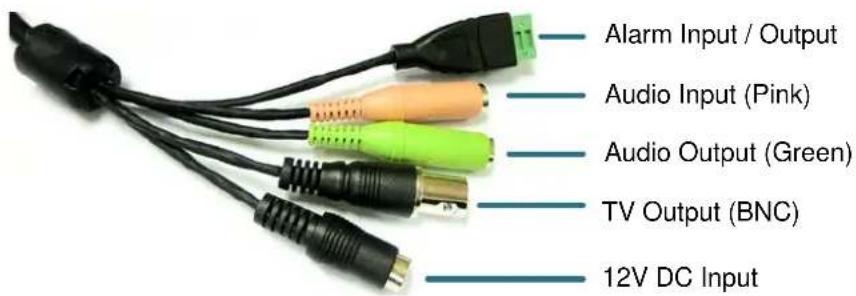
text_image
Alarm Input / Output Audio Input (Pink) Audio Output (Green) TV Output (BNC) 12V DC InputPin Assignment for Alarm Input / Output
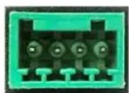
4 3 2 1
Pin 1: Alarm In
Pin 2: Alarm GND
Pin3: Alarm Out-
Pin4: Alarm Out+
3. Installation
There are two ways to mount the EDN Plus IP Dome: Wall-Surface Mount and In-Ceiling Mount.
Wall-Surface Mount:
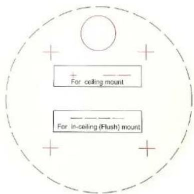
- Paste the supplied mounting template onto a desired location on the wall. Drill the four red cross marks, and the red circle mark only if you wish to run the wires into the wall.
text_image
+ For ceiling mount For in-ceiling (Flush) mountNote: The minimum recommended thickness of the wall is 1 cm.
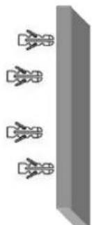
- Push the four supplied anchors into the four holes on the wall.
natural_image
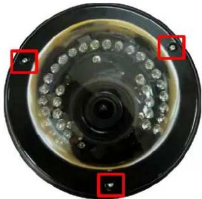
Pure diagram of four identical mechanical components mounted on a vertical panel (no text or symbols)- Unscrew the three screws by using the supplied hex screwdriver and remove the cover.
natural_image
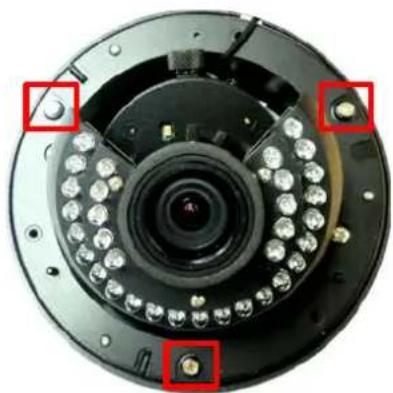
Close-up of a circular mechanical component with embedded holes and concentric rings (no text or symbols visible)- Unscrew the three screws and take out the camera body.
natural_image
Close-up of a camera lens assembly with multiple circular components and red square annotations highlighting specific parts (no text or symbols present)- Thread the cables on the side of the camera case. If you want to wire the cables through the wall, run the cables through the hole at the bottom.
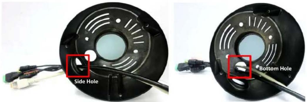
text_image
Side Hole Bottom Hole- If you run the cables through the bottom hole in Step 5, screw the circle plate on the side hole for waterproofing. You can simply tighten the circle plate using a coin.
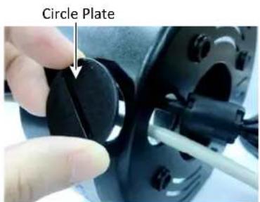
text_image
Circle Plate- Secure the camera case to the wall using the supplied four long screws.
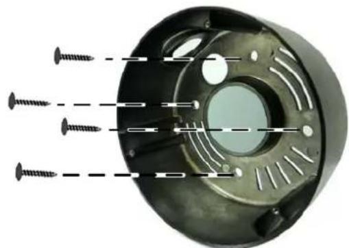
natural_image
Close-up of a mechanical component with four screws inserted, showing internal structure and mounting holes (no text or symbols)- Place and screw the camera body back to the camera case.
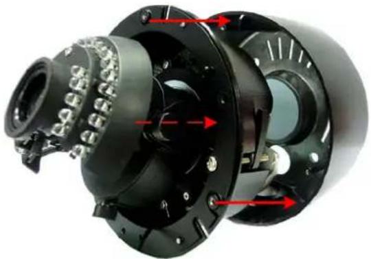
natural_image
Close-up of a mechanical device with red arrows indicating internal components (no visible text or symbols)- Connect the network, power and other cables to the camera. Refer to 2. 5-Pin Data Cable.
- Optionally insert a micro SD / SDHC card to the card slot. See No.5 in 1. Overview.
- Access the camera live view. See 5. Assigning an IP Address. Or using the TV-out cable to connect a monitor to the camera for setting image aim and focus.
- Adjust camera lens and angles.
a. Use the Zoom / Focus screws to adjust camera lens.
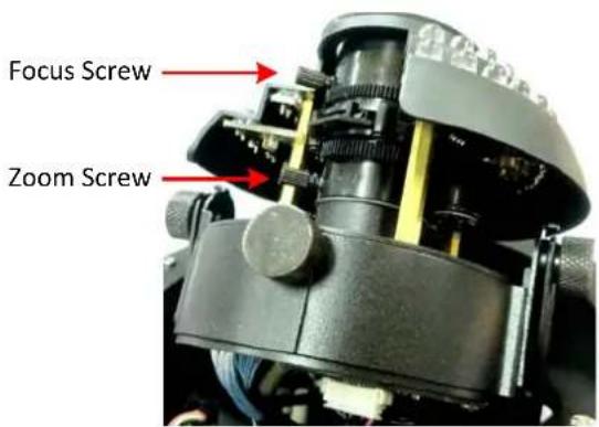
text_image
Focus Screw Zoom Screwb. To adjust the camera to a desired angle:
Pan Adjustment: Simply turn left / right of the top camera body.
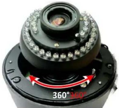
natural_image
Close-up of a black mechanical device with a camera lens and red directional arrows indicating 360° and 260° angles (no text or symbols on the device itself)Rotational Adjustment: Using the rotate screw.
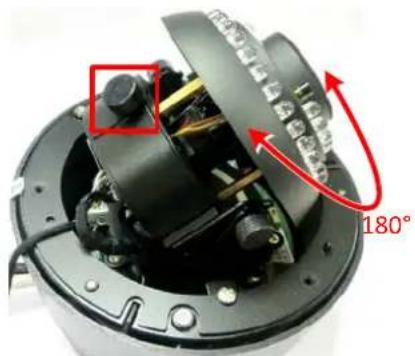
natural_image
Close-up of an electronic device with visible internal components and a 180° angle annotation (no readable text or symbols beyond measurement)Tilt Adjustment: Using the two tilt screws.
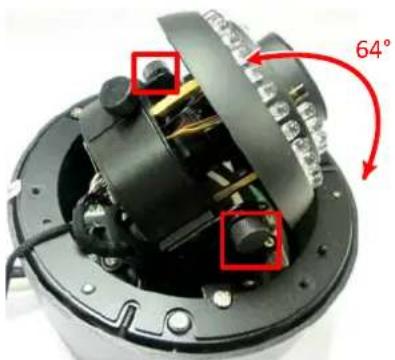
natural_image
Close-up of a mechanical device with visible components and a 64° rotation indicator (no text or symbols beyond the angle annotation)- Secure the cover back to the camera.
In-Ceiling Mount:
- Paste the supplied mounting template onto a desired location on the wall. Cut a circle on the ceiling along the circle edge of the mounting template.
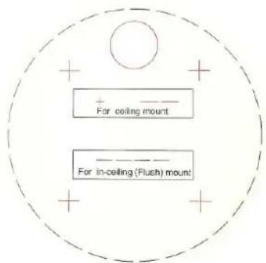
text_image
+ For ceiling mount - For in-ceiling (Flush) mount-
Follow Steps 3 to 6 in Wall-Surface Mount to take out the camera body and run the cables.
-
Place the camera body into the ceiling opening.
-
On the back side, make sure the black plastic clips are slightly above the ceiling board and pointing outward.
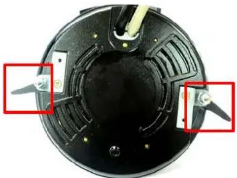
natural_image
Top-down view of a black circular electronic device with two red annotation boxes highlighting specific components (no text or symbols visible)- Tighten the bracket screws from the front side of the camera.
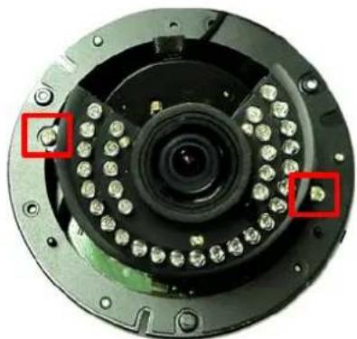
natural_image
Close-up of a camera lens assembly with red square highlights (no text or symbols visible)-
Connect the network, power and other cables to the camera. Refer to 2. 5-Pin Data Cable.
-
Optionally insert a micro SD / SDHC card to the card slot. See No.5 in 1. Overview.
-
Access the camera live view. See 5. Assigning an IP Address. Or using the TV-out cable to connect a monitor to the camera for setting image aim and focus.
-
Adjust camera lens and angles. See Step 11 in Wall-Surface Mount.
-
Secure the cover back to the camera.
4. Accessing the Camera
You have to assign an IP address for your camera to be accessible. To assign an IP address to the camera, use the IP Utility (IPU) software included in the software CD. Please connect the camera in the same LAN of your computer.

- Install and then start the IPU program IPU/day. The following dialog box appears.

text_image
IP Utility Configuration List: Check All Uncheck All MAC Address Machine Name IP Addre... IP Type Subnet M... Gateway Addr... DNS1 Addr... 00-20-11-22-35-57 EDN3340-1.0 9-B2 192.168.12.136 DHCP 255.255.255.0 192.168.12.1 192.168.10.188 19 Find Devices Login/Multi Login Set IP Address Connect to selected IP Exit Upgrade Firmware Save Configuration Load Configuration- Click Find Devices to search the cameras connected in the LAN. The default network values of the cameras will be displayed. By default, the network protocol of the camera is DHCP.
- To configure the network settings, select a camera and then click Login/Multi Login to log in.
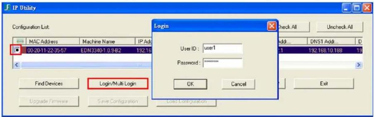
text_image
IP Utility Configuration List: MAC Address Machine Name IP Add 00-20-11-22-35-57 EDN3340-1.0.9-B2 192.16 Login User ID: user1 Password: ******** OK Cancel Find Devices Login/Multi Login Upgrade Firmware Save Configuration Load Configuration Check All Uncheck All Add... DNS1 Add... D 1 192.168.10.188 19 Exit- Type the user ID and password. Click OK.
Note:
- The default user ID is user1 and the default password is 11111111.
-
If you select more than one camera that has the same user ID / password, you will be able to log in several cameras at once.
-
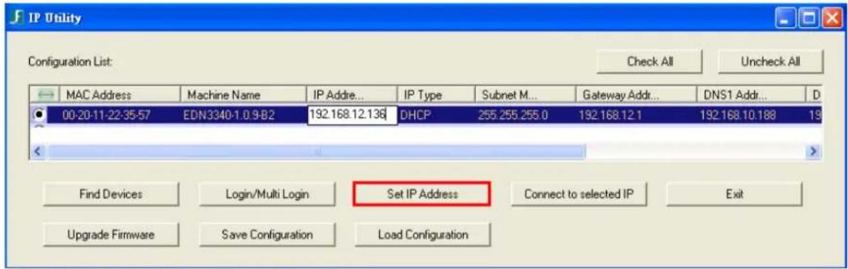
To change the IP address, double-click the IP Address of the camera. Type a new IP address and then click Set IP Address to save the settings.
text_image
IP Utility Configuration List: Check All Uncheck All MAC Address Machine Name IP Addre... IP Type Subnet M... Gateway Addr... DNS1 Addr... 00-20-11-22-35-57 EDN3340-1.0 9-B2 192.168.12.136 DHCP 255.255.255.0 192.168.12.1 192.168.10.188 19 Find Devices Login/Multi Login Set IP Address Connect to selected IP Exit Upgrade Firmware Save Configuration Load ConfigurationYou can also change the other settings by double-clicking the values. After configuring the values, click Save Configuration.
Note: Most networks uses DHCP to assign IP address, if you are unsure of your network settings, please consult your network administrators for configuration details.
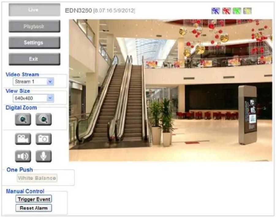
- To access the camera, highlight the camera and click Connect to Selected IP. The Internet Explorer window pops up.
- Type the user ID and password to log in. The Live View window of the camera appears.
text_image
EDN3260 [8.07.16 5/9/2012] Live Playback Settings Exit Video Stream Stream 1 View Size 640x460 Digital Zoom One Push White Balance Manual Control Trigger Event Reset AlarmNote:
- You might be required to download ActiveX for viewing the camera feed. If asked, click Yes.
- To enable Remove Live View, Firmware Upgrade and ActiveX Prompt on Internet Explorer, some settings have to be complete. Please refer to 5.2 Settings for Microsoft Internet Explorer in the User's Manual.
5. Network Connections
You can use one of the methods below to connect the camera to the network.
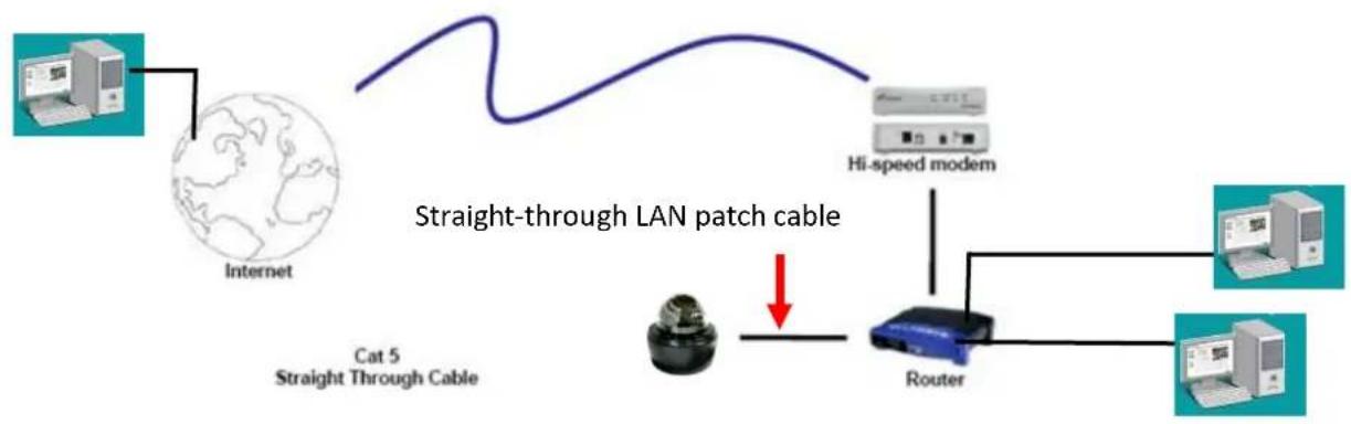
Router or LAN Connection
This is the most common connection in which the IP camera is connected to a router and allows multiple users on and off site to see the IP camera on a LAN/WAN (Internet). The camera must be assigned an IP address that is compatible with its LAN. By setting up port forwarding on the router, you can remotely access the cameras from outside of the LAN via the Internet. To remotely access the Web interface of the IP camera, please refer to 7.3.2 DDNS in the User's Manual. To set up port forwarding, please consult the manual of the router.
Router or LAN Connection
flowchart
graph LR
    A["Internet"] --> B["Cat 5 Straight Through Cable"]
    B --> C["Router"]
    C --> D["Hi-speed modem"]
    D --> E["Computer"]
    C --> F["Computer"]
    style A fill:#f9f,stroke:#333
    style B fill:#ccf,stroke:#333
    style C fill:#cfc,stroke:#333
    style D fill:#fcc,stroke:#333
    style E fill:#cff,stroke:#333
    style F fill:#ffc,stroke:#333
Right: Pinout of a straight-through cable.

flowchart
graph LR
    A["Pin 4, 5, 7 and 8 are not used"] --> B["Receive (3 & 6)"]
    B --> C["Transmit (1 & 2)"]
    C --> D["Receive (3 & 6)"]
    D --> E["Pins 4, 5, 7 and 8 are not used"]
    F["Pin number"] --> G["Wire Color"]
    H["Pin 1 => Orange/White"] --> I["Orange/White Pin 1 => Blue Pin 2 => Orange Pin 3 => Green Pin 4 => Blue Pin 5 => Blue/White Pin 6 => Green Pin 7 => Brown/White Pin 8 => Brown"]
    J["Straight-Through"] --> K["Wire"]
    L["1"] --> M["1"]
    N["2"] --> O["2"]
    P["3"] --> Q["3"]
    R["6"] --> S["6"]
Direct High-Speed Connection
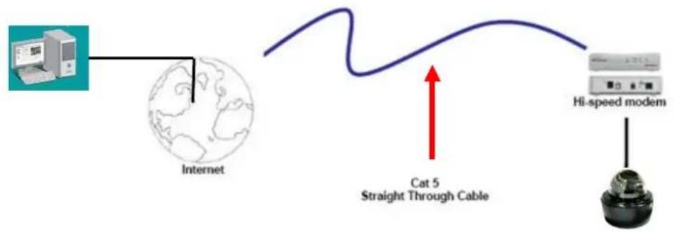
In a Direct High-Speed Connection, the camera connects directly to a modem without the need for a router. You need to set the static or dynamic WAN IP address assigned by your ISP (Internet Service Provider) in the camera's configuration web pages. To access the camera, just type "http://xxx", where xxx is the IP address given by your ISP. If you have a dynamic IP address, this connection may require that you use DDNS for a reliable connection. Please refer to 7.3.2 DDNS in the User's Manual.
Direct High Speed Modem Connection
flowchart
graph LR
    A["Internet"] --> B["Cat 5 Straight Through Cable"]
    B --> C["Hi-speed modem"]
One-to-One Connection (Directly from PC to IP Camera)
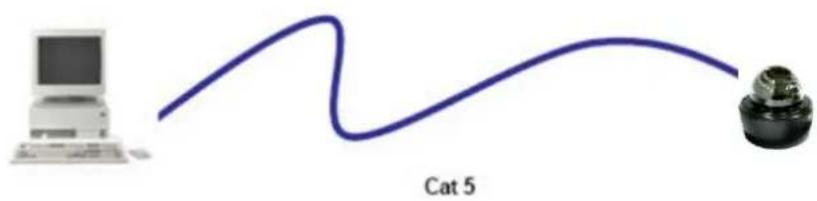
You can connect directly without using a switch, router or modem. However, only the PC connected to the camera will be able to view the IP camera. You will also have to manually assign a compatible IP address to both the computer and the IP camera. Unless the PC has another network connection, the IP camera will be the only network device visible to the PC. See the diagram below:
Simple One to One Connection
natural_image
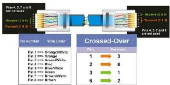
Simple line drawing of a computer and a mechanical component labeled Cat 5 (no text or symbols on the diagram itself)Right: Pinout of a crossed-over cable.
flowchart
graph LR
    A["Pins 4,5,7 and 8 are not used"] --> B["Receive (1 & 6)"]
    B --> C["Transmit (1 & 2)"]
    C --> D["Receive (3 & 0)"]
    D --> E["Transmit (1 & 2)"]
    E --> F["Pins 4,5,7 and 8 are not used"]

    subgraph Wire Color
        G["Pin 1 ==> Orange/White"]
        H["Pin 2 ==> Orange"]
        I["Pin 3 ==> Green/White"]
        J["Pin 4 ==> Blue"]
        K["Pin 5 ==> Blue/White"]
        L["Pin 6 ==> Green"]
        M["Pin 7 ==> Brown/White"]
        N["Pin 8 ==> Brown"]

    end

    subgraph Crossed-Over
        O["1"] --> P["3"]
        Q["2"] --> R["6"]
        S["3"] --> T["1"]
        U["6"] --> V["2"]
    end
6. Upgrading Firmware
You can upgrade camera's firmware using the IP Utility software, which is included in the software CD.
-
Follow Step 1 to Step 4 in 5. Assigning an IP Address to log in the camera.
-
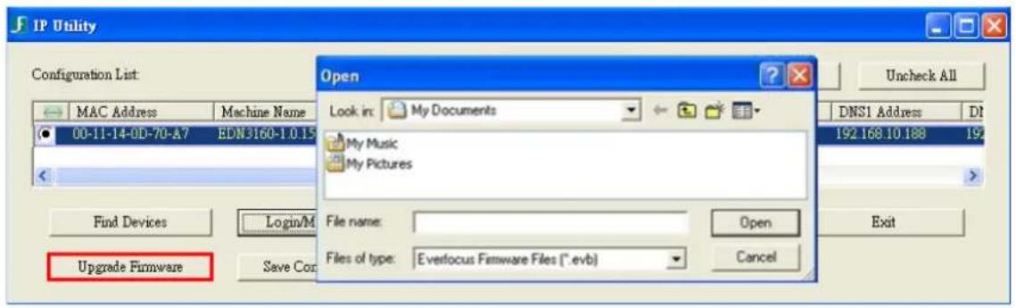
Highlight the camera and then click Upgrade Firmware. A browsing window appears.
text_image
IP Utility Configuration List: MAC Address Machine Name 00-11-14-0D-70-A7 EDN3160-1.0.15 Update Devices Login/M Upgrade Firmware Save Corp Open Look in: My Documents My Music My Pictures File name: Files of type: Everfocus Firmware Files (*.evb) Open Cancel Uncheck All DNS1 Address DI 192.168.10.188 19 Exit- Select the firmware file (.evb) and then click Open. The IP Utility will automatically upgrade the firmware.

text_image
IP Utility Configuration List Check All Uncheck All loss IP Type Subnet Mask Gateway Address DNS1 Address DNS2 Address Port Status Progress 12.102 DHCP 255.255.255.0 192.168.10.1 192.168.10.168 0.0.0.0 80 12.75 DHCP 255.255.255.0 0.0.0.0 192.168.10.188 192.168.10.189 80 CompletedThe camera will reboot once the update is complete. Click Find Devices, the new firmware version should be displayed in the last part of the Machine Name.
EverFocus Electronics Corp.
EverFocus Taiwan:
12F, No.79, Sec. 1, Shin-Tai Wu Road,
Hsi-Chih, Taipei, Taiwan
TEL: +886 2 2698 2334
FAX: +886 2 2698 2380
www.everfocus.com.tw
marketing@everfocus.com.tw
EverFocus China - Beijing:
Room 609, Technology Trade Building,
Shangdi Information Industry Base,
Haidian District, Beijing 100085, China
TEL: +86 10 6297 3336\~39
FAX: +86 10 6297 1423
www.everfocus.com.cn
marketing@everfocus.com.cn
EverFocus USA - California:
1801 Highland Avenue, Unit A, Duarte, CA 91010, USA
TEL: +1 626 844 8888
FAX: +1 626 844 8838
www.everfocus.com
sales@everfocus.com
EverFocus Japan:
5F, Kinshicho City Building, 2-13-4
Koto-Bashi, Sumida-Ku, Tokyo, 130-0022, Japan
TEL: +81 3 5625 8188
FAX: +81 3 5625 8189
www.everfocus.co.jp
info@everfocus.co.jp
EverFocus India:
Suite 803, Housefin Bhavan, C-21,
Bandra Kurla Complex, Bandra (East),
Mumbai 400051, India
TEL: +91 22 6128 8700
FAX: +91 22 6128 8705
www.everfocus.in
sales@everfocus.in

Your EverFocus product is designed and manufactured with high quality materials and components which can be recycled and reused.
This symbol means that electrical and electronic equipment, at their
end-of-life, should be disposed of separately from your household waste.
Please, dispose of this equipment at your local community waste.
your local community waste collection/recycling centre.
In the European Union there are separate collection systems for used
electrical and electronic product.
Please, help us to conserve the environment we live in!
4F, No. 2, D4 Building, Wan Yelong
Industrial Park, Tangtou Road, Shiyan,
Baoan, Shenzhen, Guangdong 518101, China
TEL: +86 755 2765 1313
FAX: +86 755 2765 0337
www.everfocus.com.cn
marketing@everfocus.com.cn
EverFocus USA - New York:
415 Oser Avenue, Unit S, Hauppauge, NY 11788, USA
TEL: +1 631 436 5070
FAX: +1 631 436 5027
www.everfocus.com
sales@everfocus.com
EverFocus Europe - UK:
Unit 12, Spitfire Business Park,
Hawker Road, Croydon Surrey, CR0 4WD, UK
TEL: +44 20 8649 9757 / +44 845 430 9999
FAX: +44 20 8649 9907
www.everfocusuk.co.uk
salesuk@everfocus.com

EverFocus®
P/N: 4605PD3340B010A-Ver.B