Itona Md24 - Desktop computer VXL - Free user manual and instructions
Find the device manual for free Itona Md24 VXL in PDF.


User questions about Itona Md24 VXL
0 question about this device. Answer the ones you know or ask your own.
Ask a new question about this device
Download the instructions for your Desktop computer in PDF format for free! Find your manual Itona Md24 - VXL and take your electronic device back in hand. On this page are published all the documents necessary for the use of your device. Itona Md24 by VXL.
USER MANUAL Itona Md24 VXL
natural_image
Black VXL ITDA power supply unit with dual leads and ventilation slots (no visible text or symbols on main body)
text_image
VXLItona M, Md, Md+ Series
Hardware User Guide
Copyright © 2004-2014 VXL Instruments Limited. All Rights Reserved
Information in this document is subject to change without notice and does not represent a commitment on the part of the manufacturer. No part of this guide may be reproduced or transmitted in any form or means, electronic or mechanical, including photocopying and recording, for any purpose, without the express written permission of the manufacturer.
Every effort has been made to make this guide as complete and as accurate as possible, but no warranty or fitness is implied. The authors and the publisher shall have neither responsibility nor liability to any person or entity with respect to loss or damages arising from the use of information contained in this guide. This disclaimer does not apply in countries where such provisions are inconsistent with local law.
All Trademarks are acknowledged.
Last Updated: February, 2014.
Version: IMd/UG-09-14.
Part No: 600011054045 A00.
VXL Instruments Ltd.,
House of Excellence,
No. 17, Electronics City,
Hosur Road,
Bangalore- 560 100, INDIA.
www.vxl.net
Federal Communication Commission (FCC) Statement
This equipment has been tested and found to comply with the limits for a Class B digital device, pursuant to Part 15 of the FCC Rules. These limits are designed to provide reasonable protection against harmful interference in a residential installation. This equipment generates, uses, and can radiate radio frequency energy and, if not installed and used in accordance with the instructions, may cause harmful interference to radio communications. However, there is no guarantee that interference will not occur in a particular installation.
If this equipment does cause harmful interference to radio or television reception, which can be determined by turning the equipment Off and On, the user is encouraged to try to correct the interference by one or more of the following measures:
• Reorient or relocate the receiving antenna.
- Increase the separation between the equipment and receiver.
- Connect the equipment to an outlet on a circuit different from that to which the receiver is connected.
- Consult the dealer or an experienced radio/television technician for help.
Each Thin Client is equipped with a FCC compliance label that shows only the FCC identification number. The full information of the associated label is as follows:
This device complies with Part 15 of the FCC rules. Operation is subject to the following two conditions:
- This device may not cause harmful interference.
- This device must accept any interference received, including interference that may cause undesired operation.
Battery Information
Batteries, battery packs, and accumulators should not be disposed together with the general household waste. In order to forward them to recycling or proper disposal, please use the public collection system for electronic waste in your country.
Product Safety
Improper connecting or mounting of the product could result in product failure or damage. Refer to the Md Series Installation Guide for more information about setting up the thin client.
VXL Technical Support
To access VXL hardware and software documentation, visit:
http://www.vxl.net//Independent/product-manuals.aspx
For online support or reporting a problem, visit:
http://www.vxl.net/Support/Online-support.aspx
For more details about Product Warranty, visit:
http://www.vxl.net/Support/Product-Warranty-Terms.aspx
ENERGY STAR Compliant Product

ENERGY STAR is a joint program of the U.S. Environmental Protection Agency and the U.S. Department of Energy helping us all save money and protect the environment through energy efficient products practices.
Please visit http://www.energystar.gov for detail information on the ENERGY STAR joint program.
Regulatory Certifications











RoHS

Table of Contents
Federal Communication Commission (FCC) Statement i
Battery Information i
Product Safety i
VXL Technical Support i
ENERGY STAR Compliant Product ii
Regulatory Certifications iii
1 Introduction 1
Features 2
Optional Features 2
About the User Guide 2
Abbreviations and Acronyms 2
User Manual Organization 3
2 Installation 5
Unpacking the Unit 5
Preparing to Connect 5
Accessing the Secure USB Shell 6
Installing the Pedestal 8
Fixing the External Antenna 9
Mounting using VESA Dock 9
Mounting using the Pedestal 12
Connecting the Cables and Power Supply 13
Using the Power Cord Anchor 17
Using the Kensington Lock 17
Connecting to the Server 18
3 Specifications 19
Hardware 19
Mechanical 20
Operating Environment 20
Power 20
External Power Adapter 21
4 Troubleshooting
22
Locating the Serial Number 22
Recommended Orientation 22
Replacing the Battery 22
General Troubleshooting 23
Reporting a Problem 23
Appendix 24
VXL Extended Standard Warranty 24
Limited Lifetime Customer Hardware Support 24
Compatible Renewable Energy Accessories 24
Product Disposal (For EU-member countries) 24
Connectors 25
1 Introduction
Thin Clients are terminal devices that connect to multi-user application servers operating under Citrix XenDesktop, XenApp, VMware View connection server and Windows 2003/2008 terminal servers.
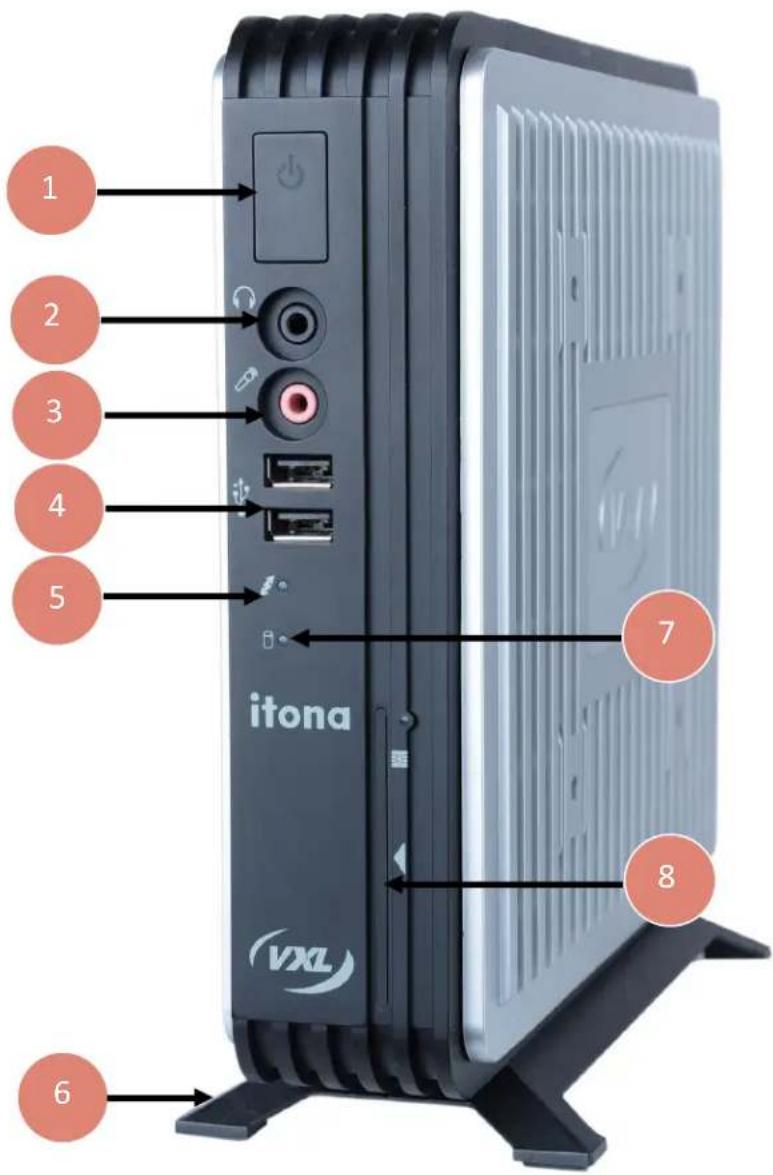
This guide covers installation procedure and hardware details of Itona M / Md / Md+ series.
text_image
1 2 3 4 5 itona VXL 7 8 6- Power Button.
- Audio Out Port
- Mic
- Two USB Ports
- Link LED
- Pedestal
- HDD LED
- Smart Card Reader (Optional)
Figure 1-1: Itona M / Md / Md+ Series Front View
Itona M / Md / Md+ series delivers smart and robust solutions for thin client computing. It is an aesthetically and ergonomically designed compact desktop, providing simultaneous full screen connectivity to Windows and UNIX application servers. Itona M / Md / Md+ series is a powerful business alternative to users using Win32 applications while continuing access to legacy UNIX applications.
This thin client communicates with application servers via the ICA protocol developed by Citrix Systems Inc., Remote Desktop Protocol from Microsoft and a host of other popular connectivity protocols.
Features
This thin client is equipped with a Gigabit Ethernet port that provides instant connection to multi-user Windows NT application servers. Display Port, DVI-I, USB and PS/2 compatible keyboard/Mouse ports are available for quick set up and use.
Optional Features
Following are the optional features available:
- 1 x COM port
- DP to DVI-I cable
- DP to HDMI cable
- DP to VGA cable
• Mini PCIe wireless LAN + Antenna
• Power Cord (Country specific) - USB smart card reader
- USB WLAN
- Mouse
- VESA Dock
Note: Please contact the reseller or dealer from whom you purchased the product for information about the optional features.
About the User Guide
This User Guide provides step-by-step instructions to install Itona M / Md / Md+ series thin client. The specifications and troubleshooting steps are also included.
Abbreviations and Acronyms
Abbreviation Expansion
AC Alternating Current
DC Direct Current
DP Display Port
DVI-I Digital Visual Interface (Digital and Analog)
DVI-D Digital Visual Interface (Digital)
LAN Local Area Network
LED Light Emitting Diode
TCP/IP Transmission Control Protocol/Internet Protocol
USB Universal Serial Bus
VESA Video Electronics Standards Association
VGA Video Graphics Array
User Manual Organization
Chapter No Chapter Name Description
1 Introduction This chapter contains an overview of the product, information about this guide and abbreviations used in this guide.
2 Installation This chapter contains the procedure to set up the hardware.
3 Specifications This chapter contains hardware, mechanical, electrical, interface and operating environment specifications
4 Troubleshooting This chapter contains solutions to problems that you may encounter while using the product.
— Appendix This chapter contains detailed specifications for connectors and cables used with the product.
Warning
- Any changes or modifications not expressly approved by the party responsible for compliance could void the user's authority to operate this equipment.
- There are no user serviceable parts inside. Do not open enclosure, hazardous voltages present in the equipment's components. Do not disassemble the equipment as this can nullify your warranty.
- Connect the equipment to an earthed three-pin socket to avoid electrical shocks.
- As a precaution, the AC socket outlet should be near the equipment and should be easily accessible.
- Excessive sound from earphones and headphones can cause hearing damage or loss. Avoid setting the volume setting to maximum.
! Caution
- Only equipment certified to comply with Class B (computer input/output devices, terminals, printers etc.) should be connected to this equipment, and must have shielded interface cables.
• This equipment should not be used in electro-medical applications. - Do not operate this equipment in corrosive or explosive environment.
- Replace the battery only with the same or equivalent type recommended by the manufacturer.
- Do not operate this equipment beyond temperature limits provided in the 'Operating Environment' section.
2 Installation
Perform the following steps to successfully install and set up Itona M / Md / Md+ series.
- Unpack the unit.
- Prepare to connect.
- Connect the secure USB shell devices.
- Install the pedestal.
- Fix the external antenna (Optional).
- Install the VESA Dock (Optional).
- Connect the cables and power supply.
- Connect to the server.
The installation sequence is explained in the following sections of this chapter.
Unpacking the Unit
Unpack the unit from its carton; handle safely to avoid damage to the thin client.
The carton shipped to you contains the following:
• Itona M / Md / Md+ series thin client
• Power adapter 19 V
• Power cord country specific (Optional)
- Mouse (Optional)
• DVI-I to VGA dongle (Type M)
- Pedestal
• Hardware Installation Guide

Note: Please retain the original carton and packing material for future use.
Preparing to Connect
Before you connect and start using the thin client, ensure that the following are available.
- Appropriate country specific power cord.
• A well ventilated, clean, dry and dust-free place to install this thin client. - A minimum space of 2 inches (5 cm) on the sides of the unit for efficient convection cooling.
- Specified environmental conditions. For more information, see section 'Operating Environment'.
Accessing the Secure USB Shell

Note: No user serviceable parts inside the thin client. Please contact a VXL authorized service professional to remove the casing and access the secure USB shell.

Warning: Hot temperatures inside the thin client. Switch off and unplug the device, leave it idle for at least 30 minutes before removing the top and the bottom strips of the thin client.
Two USB ports are provided in the secure USB Shell. These ports are used in banking and other secure IT implementations. The secure USB shell prevents wrongful use of these USB ports. To use the secure USB ports:
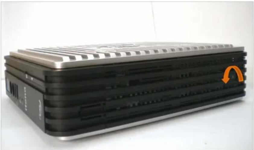
- Remove the screws from the top and bottom strips of the thin client.
natural_image
Black and silver electronic device with ventilation grilles and a circular orange button on the right side (no visible text or symbols)Figure 2-1: Bottom Strip Screw
- Slide and remove the side panels.

Warning: Do not remove the screws of the aluminum metal enclosure.
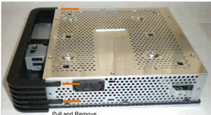
- Gently pull the bezel tabs outward on both the top and bottom strips simultaneously as shown in the following figure.
natural_image
Interior view of a computer drive chassis showing ports, connectors, and ventilation grilles (no text or symbols visible)Figure 2-2: Removing the Front Bezel

Caution: Pull out the tabs gently out of its groove.
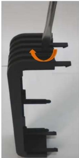
- Break open the secure shell USB wire seal in the front bezel using a screwdriver as shown in the following figure.
natural_image
Close-up of a black plastic mechanical component with a handle and orange accent (no text or symbols visible)Figure 2-3: Opening the Secure Shell USB Wire Seal

Note: A gentle clockwise rotation of the screwdriver will break the wire seal. Do not apply weight on the seal.
-
Connect the USB devices to the two secure USB device ports.
-
Fix the front bezel and allow the USB cables through the Secure USB shell opening.
-
Replace the top and the bottom strips and fasten the screws.
Installing the Pedestal
Fix the pedestal to the bottom of the thin client before you place it on a flat surface. Do not fix the pedestal if you are mounting this thin client using the VESA bracket. For more information about mounting using a VESA bracket, see section 'Mounting using VESA Dock'.
To install the pedestal:
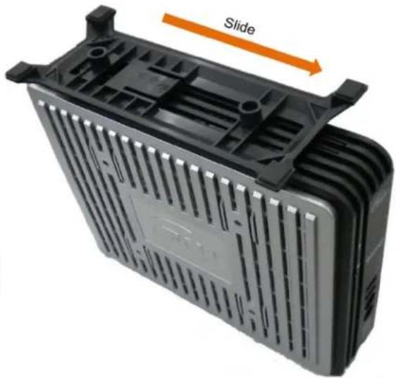
- Turn the Thin Client upside down.
- Locate the slots at the bottom of the Thin Client into which the tabs on the pedestal fit.
natural_image
Exterior view of a black plastic heat exchanger housing with ventilation slots and a slide indicator (no text or symbols on the device itself)Figure 2-4: Installing the Pedestal
- Insert the pedestal tabs into the slots on the Thin Client and then slide the pedestal. You will hear a snap sound indicating that the pedestal is fixed in place.
To remove the pedestal:
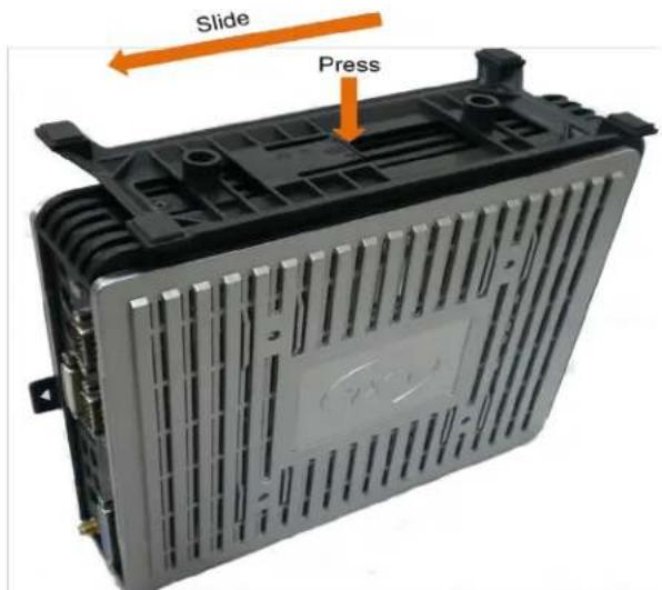
- Turn the thin client upside down.
text_image
Slide PressFigure 2-5: Removing the Pedestal
- Press the tab and then slide the stand outwards and lift the pedestal off the thin client.
Fixing the External Antenna
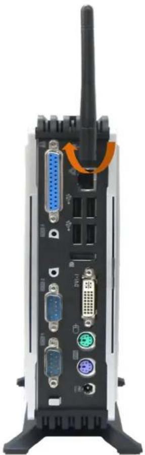
An external antenna is used to receive wireless LAN signals. To fix an external antenna:
- Connect the antenna to the WLAN port in the back panel of the thin client.
natural_image
Back view of a wireless router or network device showing ports, connectors, and a antenna (no visible text or labels)Figure 2-6: Fixing the External Antenna
- Fasten the antenna by rotating it clockwise as shown in Figure 2-6.
Mounting using VESA Dock
VESA is an industry standard for interfaces used to mount flat panel monitors, flat panel television and thin clients. Four screw slots in the side panels of this thin client allow you to install the VESA dock.

Note: The VESA dock is an optional feature and has to be purchased separately. You will receive the VESA dock in a separate carton.
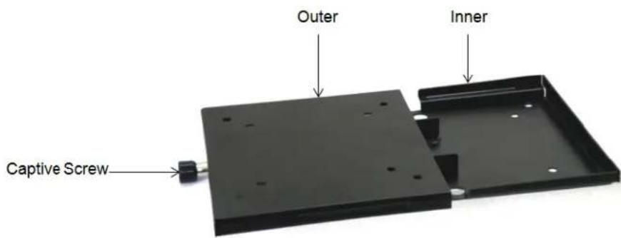
The VESA Dock consists of two parts – VESA Inner and VESA Outer. These parts are made of rugged 1.2 mm Mild Steel sheets. The dock can be used for 75x75 mm as well as 100x100 mm VESA holes. The VESA Outer slides over the VESA Inner as shown in the following figure.
text_image
Outer Inner Captive ScrewFigure 2-7: VESA Outer and Inner
To install the VESA Dock:
- Using the screws provided, attach the VESA Outer to the thin client.
- Using the screws provided, attach the VESA Inner to the surface where you want to mount the thin client.
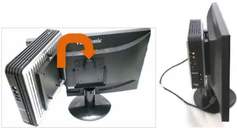
- Slide the VESA Outer over the VESA Inner. A metallic clunk sound indicates that the two parts are securely fixed as shown in the following figure.
natural_image
Two views of a computer monitor: one showing internal components with an orange arrow pointing to a labeled 'Vidronic' component, the other showing external ports and cables (no readable text or symbols)Figure 2-8: Mounting the Thin Client using VESA
- Use a screwdriver to fasten the captive screw at the top of the dock.
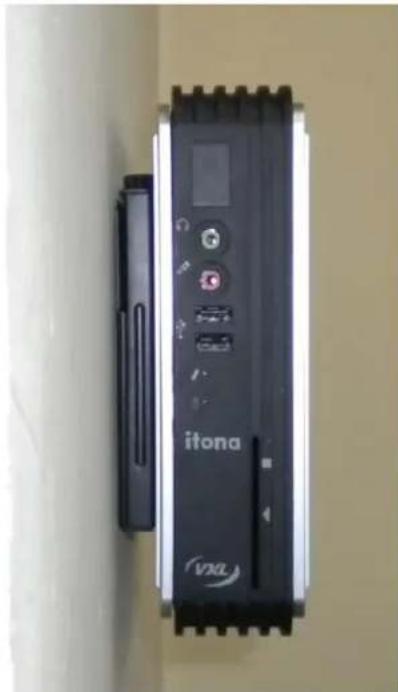
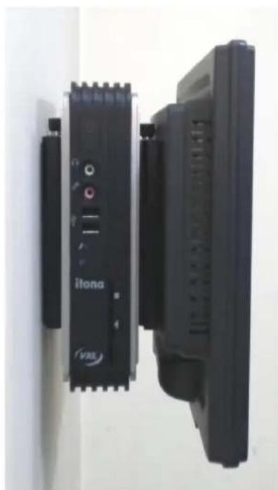
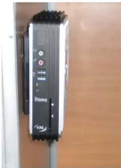
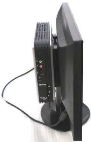
Following are the various VESA Dock mounting options:
natural_image
Close-up of a black and white electronic device labeled 'itona' with control buttons and a VXL logo, mounted on a wall (no readable text beyond branding)Figure 2-9 Wall Mounted Client
natural_image
Close-up of two black electronic devices mounted on a wall, one labeled 'ltona' and the other with visible ports (no readable text beyond labels)Figure 2-10: Wall Mounted Client and Monitor
natural_image
Close-up of a black electronic device labeled 'itona' mounted on a wooden surface, with no visible text or symbols beyond the label.Figure 2-11: Under the Counter Left
natural_image
Black electronic device with a speaker and antenna, connected to a stand (no visible text or symbols)Figure 2-12: Behind the Monitor
Mounting using the Pedestal
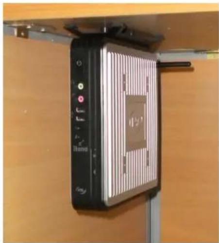
You can mount the thin client under the counter top using the pedestal. To mount the thin client under the counter top:
natural_image
Close-up of a black electronic device mounted on a wooden cabinet, showing a vertical panel with a grid and control buttons (no visible text or symbols)Figure 2-13: Mounting under the Counter Top
- Place the pedestal under the counter top.
- Using the two screws provided, attach the pedestal under the counter top.
- Slide fit the thin client to the pedestal. A snap sound indicates that your thin client is securely fixed.
To remove the thin client and the pedestal:
- Using a screwdriver, unlock the pedestal lock as shown in the following figure.
Note: Hold the thin client in place while unlocking the pedestal.

natural_image
Close-up of a black and white electronic device labeled 'itona' hanging from a stand, with no visible text or symbols on the device itself.Figure 2-14: Removing the Client
- Slide the thin client to remove it from the pedestal.
- Using a screwdriver, remove the two screws used to attach the pedestal.
- Remove the pedestal.
Connecting the Cables and Power Supply
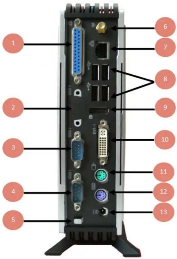
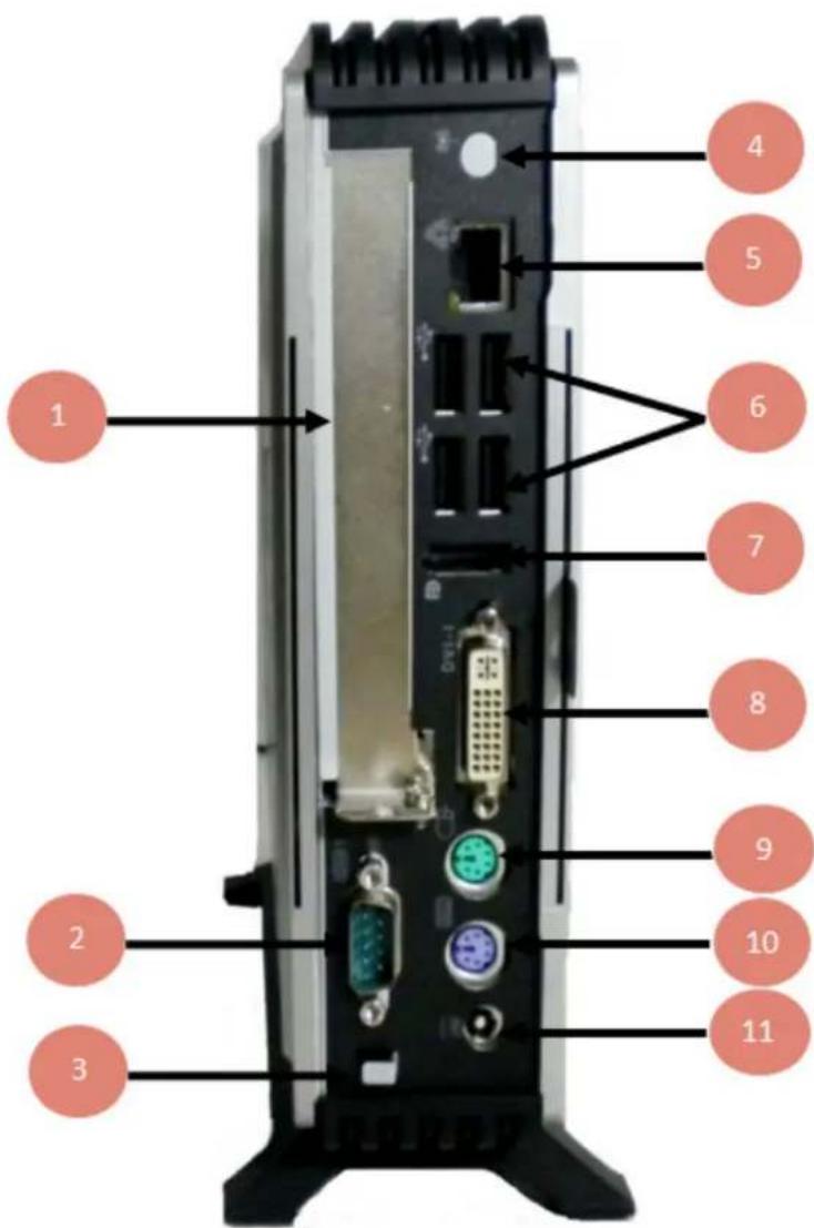
The various connectors available on the rear panel of the client are shown in Figure 2-15.
text_image
1 2 3 4 5 6 7 8 9 10 11 12 13- LPT Port
- COM Port 3 (Optional)
- COM Port 2
- COM Port 1
- Power Cord Anchor
- Mini PCIe Wireless LAN
- Ethernet Port
- Four USB Ports
- Display Port
- DVI-I Port
- PS/2 Mouse Port
- PS/2 Keyboard Port
- DC Power In
Figure 2-15: Itona M/Md Series Rear View
text_image
1 2 3 4 5 6 7 8 9 10 11Figure 2-16: Itona Md+ Series Rear View
- Graphics Card (Optional)
- COM Port 1
- Power Cord Anchor
- Mini PCIe Wireless LAN (Optional)
- Ethernet Port
- Four USB Ports
- Display Port
- DVI-I Port
- PS/2 Mouse Port
- PS/2 Keyboard Port
- DC Power In
| Connectors | Connector Symbol |
| VGA Port |  |
| DVI-I Port |  |
| USB Port |  |
| Audio Out Port |  |
| Mic Port |  |
| Display Port | 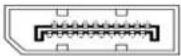 |
| PS/2 Keyboard Port |  |
| PS/2 Mouse Port |  |
| COM Port |  |
| Ethernet Port (RJ45) | 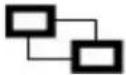 |
Table 1: Connector Symbols
Note: Before connecting any cable, ensure that the power cable is unplugged from the unit.
Refer to the connector symbols provided in 'Table 1: Connector Symbols' to connect the cables to their respective ports. Connect the cables and power supply to the unit in the following order:
- Connect PS/2 keyboard to the PS/2 Keyboard Port.
- Connect PS/2 mouse to the PS/2 Mouse Port.
- Connect the USB devices to the USB Ports.
- Connect the monitor to the Display port, DVI-I Port or the VGA Port (via DVI-I to VGA dongle). You can connect dual monitors in the following configurations:
Dual Digital Monitors
a. DP and DVI
b. DVI and DVI (via DP to DVI-I cable*)
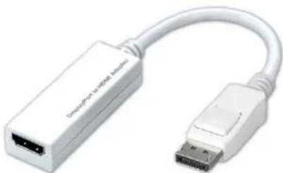
c. DVI and HDMI (via DP to HDMI cable**)
Dual Analog Monitors
Digital and Analog Monitors
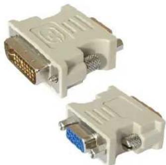
a. DP and VGA (via DVI-I to VGA dongle)
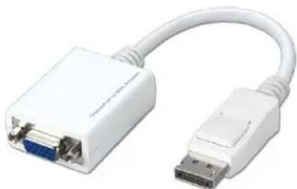
b. DVI-I and VGA (via DP to VGA cable*)
natural_image
White USB connector with two ports, showing a U8 port and cable (no text or symbols visible)Figure 2-17: DP to VGA Cable ^#

natural_image
White USB connector with DTA connector and USB port, no visible text or symbolsFigure 2-18: DP to DVI-I Cable*
natural_image
White USB connector with cable, showing network ports and port (no text or symbols visible)Figure 2-19: DP to HDMI Cable* *
natural_image
Two white DVI connectors with gold and blue metal components, shown from front and side views (no text or symbols visible)Figure 2-20: DVI-I to VGA Dongle
*The cables are optional and sold separately. Contact the reseller or dealer from whom you purchased the product for more information.
- Connect the external powered speakers to the Audio Out Port.
- Connect the microphone to the Mic Port.
- Connect serial devices to the COM Ports.
- Connect the LAN cable to the RJ45 Ethernet port.
- Connect the power adapter to the DC Power In.
Caution: Ensure that the COM 1, COM 2, COM 3, DVI-I and VGA ports are adequately fastened with the captive screws provided along with the cables.
Using the Power Cord Anchor
Power cord anchor prevents the power cord from inadvertently getting disconnected. To use the power cord anchor, press a loop of the power cord into the anchor as shown in the following image.

natural_image
Two black server racks with connected ports and cables, one showing a cable connector (no visible text or symbols)Figure 2-21: Power Cord Anchor
Using the Kensington Lock
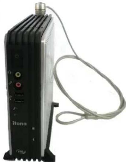
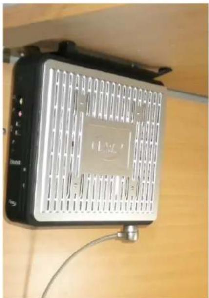
Kensington Lock secures your thin client from unauthorized removal and theft. There are two Kensington Lock slots provided at the top and bottom strips of this thin client. Purchase a compatible Kensington lock to use with these slots.
natural_image
Black electronic device labeled 'itona' with attached cable, no visible text or symbols on bodyFigure 2-22: Kensington Lock Slot on the Top Strip
natural_image
Close-up of a black and silver electronic device mounted on a wooden shelf, with no visible text or symbols.Figure 2-23: Kensington Lock Slot on the Bottom Strip
Connecting to the Server
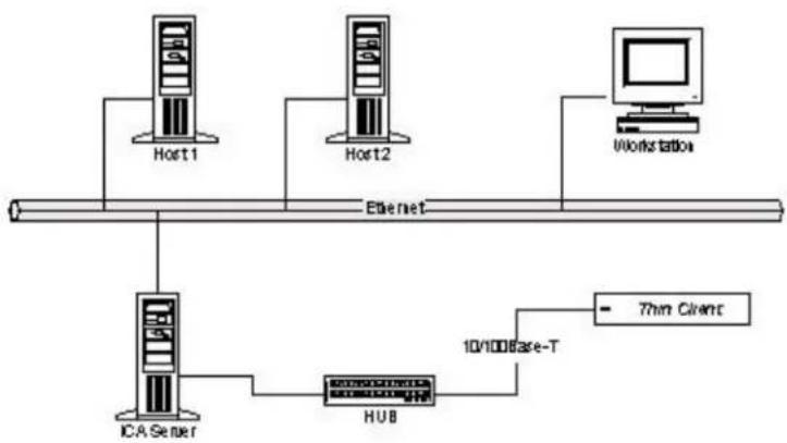
The thin client can be connected to the server/network by using a LAN connection through TCP/IP.
To connect the client to a Local Area Network through TCP/IP.
-
Connect one end of an Ethernet cable to the Ethernet Port in the client.
-
Connect the other end to a LAN hub as shown in Figure 2-24.
flowchart
graph TD
    A["Host1"] --> B["ICAServer"]
    C["Host2"] --> B
    D["Workstation"] --> E["HUB"]
    B --> F["10/100 Base-T"]
    E --> F
    F --> G["Thin Client"]
    style A fill:#f9f,stroke:#333
    style C fill:#f9f,stroke:#333
    style D fill:#ccf,stroke:#333
    style B fill:#cff,stroke:#333
    style E fill:#ffc,stroke:#333
    style F fill:#cfc,stroke:#333
    style G fill:#fcc,stroke:#333
Figure 2-24: LAN Connection through TCP/IP
- Press the power button to switch on the thin client. The front panel LED lights up and you will hear a beep. Subsequently, the operating system start-up screen appears.
3 Specifications
Hardware
Processor
Md / Md +: VIA Eden U4200 1 GHz Dual Core
M : VIA Nano U3300 1.2 GHz Single Core
North Bridge VIA VX900
Flash SSD 22 Pin
RAM 1 GB \~ 4 GB DDR3 1066 MHz
Graphic Processor Integrated Chrome9 HD DX9 3D/2D
VGA Memory
Default 256 MB (Adjustable in the range of 32 to 512 MB)
Maximum Display resolution
VGA (Via VGA dongle-Type M): 1920 x 1200, 60 Hz, 16/32 bit color.
DVI-I: 1920 x 1200, 60 Hz, 16/32 bit color.
Display Port: 2048 x 1536, 75 Hz 16/32 bit color.
Front Panel Power Button
Link LED
HDD LED
2 x USB
Mic
Headphone Port
Rear Panel COM1, COM2 Ports
1 x Parallel Port
4 x USB 2.0
PS/2 Keyboard
PS/2 Mouse
1 x DVI-I Port (VGA via dongle)
1 x Display Port
Kensington Slot
External Antenna (Optional)
Secure USB Shell 2 x USB 2.0
Networking Gigabit LAN
Wake-on-LAN
Internal Features Mono speaker
1 x PCIe slot
1 x mPCIe slot
Optional Features COM3 Port
Mini PCIe WLAN with external antenna
Smart card reader
USB WLAN dongle
DP to DVI converter cable
DVI-I splitter cable (DVI-I to DVI+VGA in extended mode)
VESA Dock (100 x 100 or 75 x 75 mm mounting holes)
Mechanical
Height 201 mm
Width 56 mm
Depth 222 mm
Weight 1.40 Kg Approx
Operating Environment
Operating temperature 0
^ C to 40^ C
Storage temperature - 20
^ C to +60 ^ C
Humidity
20% to 80% RH non-condensing
Power
Power Consumption
Idle State: 11 W
Off State: 0.2 W
External Power Adapter
Line Voltage
100 V to 240 V AC (+6,-10%)
DC Output 19 V 3.42 A
Efficiency >85%
4 Troubleshooting
This chapter contains solutions for problems you may encounter while using this product.
Locating the Serial Number
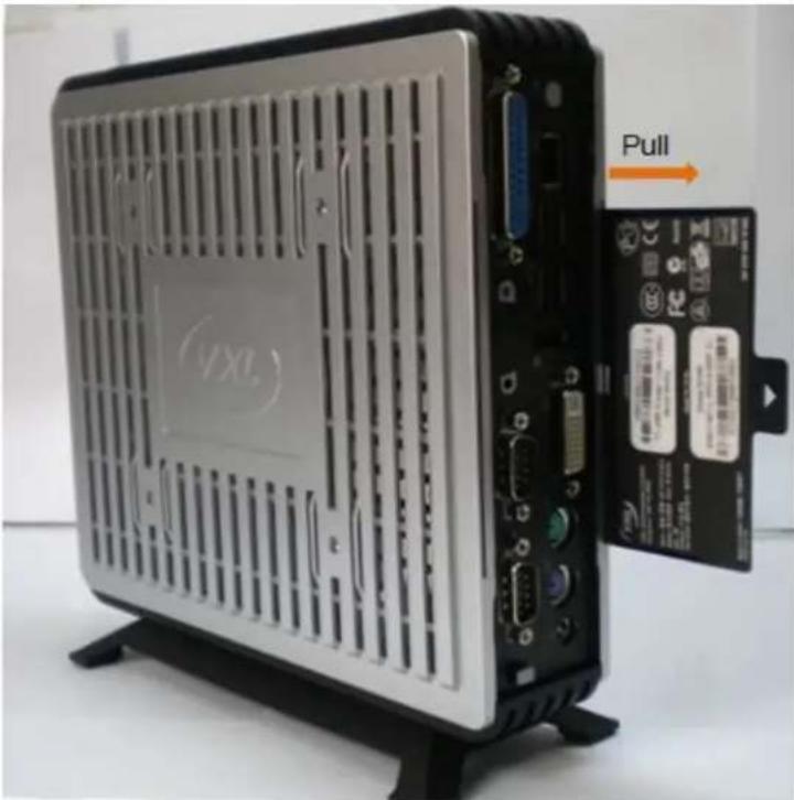
A unique serial number for this thin client is provided in an inlay card. Quote this serial number when requesting for after-sales service.
natural_image
Front view of a desktop computer chassis with ventilation slots and external hardware (no visible text or symbols)Figure 4-1: Locating the Serial Number
Recommended Orientation
We recommend that you place or install this thin client vertically; this allows natural heat dissipation. We do not recommend placing the device horizontally. Do not block the air vents on the sides.
Replacing the Battery
Contact a VXL authorized professional technician to replace the battery in your thin client.
General Troubleshooting
Following are solutions to some of the commonly encountered issues because of the system set up:
Problem Solution
The power-LED on the front panel does not glow when the client is switched on.
√ Ensure that the power cord is plugged into an AC outlet.
√ Check the fuse in the power-plug, if available.
√ Ensure that the video cable is properly connected.
There is no display on the monitor, though the power-indicating LED glows.
The mouse (or keyboard) does not work when the client is switched on.
√ Ensure that the mouse (or keyboard) is plugged in the correct PS/2 port.
Reporting a Problem
You can report a specific problem to the VXL after-sales service. To report a problem or check the status of your issue go to http://www.vxl.net/Support/Online-support.aspx.

Note: For more information about reporting a problem and checking its status, refer to the Itona M / Md / Md+ series Installation Guide document shipped with your product.
Appendix
VXL Extended Standard Warranty
VXL offers the choice of an optional limited warranty extension for up to 3 years in addition to the standard three years limited warranty for certain equipment.
For full terms and conditions for the VXL Extended Standard Warranty, please refer to the same terms & conditions as detailed in the Standard Warranty policy. Please note that in order to qualify for the Extended Warranty policy; it must be purchased at the same time as the VXL thin client devices.
For Standard Warranty policy, visit: http://www.vxl.net/Support/Product-Warranty-Terms.aspx
Limited Lifetime Customer Hardware Support
Five Year Limited Agreement on VXL Instruments Ltd Spare Parts and/or Compatible Replacement Parts
VXL Instruments agrees to provide ongoing customer/hardware support in terms of spare parts and / or compatible replacement parts for up to five years from the end of life of the hardware product. See hardware product warranty ‘Terms and Conditions’ for full details.
Further information on how to obtain replacement parts can be provided to the customer on request. The customer can also opt for additional on-site support to the existing limited warranty agreement at an extra charge.
For full 'Terms and Conditions' please visit: http://www.vxl.net/Support/Product-Warranty-Terms.aspx
Compatible Renewable Energy Accessories
With the worldwide evolution of the energy renewable market, VXL Instruments is committed to working with partners / customers to harness the benefits of this growing energy source.
Powering hardware products, including thin clients, using renewable energy is now readily and commercially available. To find out how you can make your thin client hardware even more environmentally friendly, please contact your respective reseller or supplier in your region or country for further details.
Product Disposal (For EU-member countries)
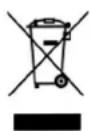
Electronic goods should be disposed off separately. Do not dispose this product along with other household waste. Batteries and integrated components can be disposed off as part of the product; they will be removed and recycled separately.
For more information about used electronic goods collection and recycling program in your area, contact the local government office or the retailer who sold this product to you.
Connectors
The following section provides pin details for various connectors on the rear panel of the client.
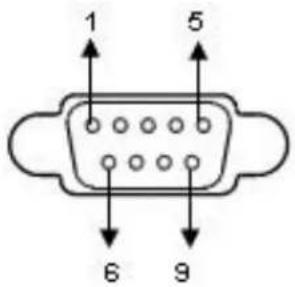
COM Port
9-pin D-type male connector, RS232C compatible, operating at 115.2 K baud maximum.
text_image
1 5 6 9Pin Signal Description
1 DCD Data Carrier Detect
2 RxD Receive Data
3 TxD Transmit Data
4 DTR Data Terminal Ready
5 GND Signal Ground
6 DSR Data Set Ready
7 RTS Request To Send
8 CTS Clear To Send
9 NC Not Connected
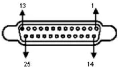
Printer Port (Parallel)
25-pin D-type female connector. ECP/EPP compatible.
text_image
13 1 25 14Pin Signal
1 STROBE
2-9 DATA 0-7
10 ACKNOWLEDGE
11 BUSY
12 PAPER END
15 ERROR
18-25 GROUND
Display Port
20 pin port with 1.62, 2.7, or 5.4 Gbit/s data rate per lane; 1, 2, or 4 lanes; 1 Mbit/s or 720 Mbit/s for the auxiliary channel.

text_image
16 17 18 19 20 21 22 23 24 25 26 27 28 29 30 31 32 33 34 35 36 37 38 39 40 41 42 43 44 45 46 47 48 49 50 51 52 53 54 55 56 57 58 59 60 61 62 63 64 65 66 67 68 69 70 16 17 18 19 20 21 22 23 24 25 26 27 28 29 30 31 32 33 34 35 36 37 38 39 40 16 17 18 19 20 21 22 23 24 25 26 27 28 29 16 17 16 16 16 16 16 16 16 16 16 16 16 16 16 16 16 16 16 16 16 16 16 16 16 16 16 16 16 16 16 16 16 16 16 16Pin Signal
1 Lane 0 (positive)
2 Ground
3 Lane 0 (negative)
4 Lane 1 (positive)
5 Ground
6 Lane 1 (negative)
7 Lane 2 (positive)
8 Ground
9 Lane 2 (negative)
10 Lane 3 (positive)
Pin Signal
11 Ground
12 Lane 3 (negative)
13 Connected to Ground
14 Connected to Ground
15 Auxiliary Channel (positive)
16 Ground
17 Auxiliary Channel (negative)
18 Hot Plug Detect
19 Return for Power
20 Power for connector (3.3 V 500 mA)
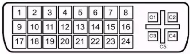
DVI-I Port
Pin C1 to C5 carry the analogue signal.24+5 pin DVI Connector.
text_image
1 2 3 4 5 6 7 8 9 10 11 12 13 14 15 16 17 18 19 20 21 22 23 24 C1 C2 C3 C4 C5| Pin | Signal | Pin | Signal | Pin | Signal |
| 1 | TMDS Data 2- | 11 | TMDS Data 1/3 Shield | 21 | TMDS Data 5+ |
| 2 | TMDS Data 2+ | 12 | TMDS Data 3- | 22 | TMDS Clock Shield |
| 3 | TMDS Data 2/4 Shield | 13 | TMDS Data 3+ | 23 | TMDS Clock + |
| 4 | TMDS Data 4- | 14 | +5 V Power | 24 | TMDS Clock - |
| 5 | TMDS Data 4+ | 15 | Ground(for+5V) | C1 | Analog Red |
| 6 | DDC Clock | 16 | Hot Plug Detect | C2 | Analog Green |
| 7 | DDC Data | 17 | TMDS Data 0- | C3 | Analog Blue |
| 8 | Analog Vertical Sync | 18 | TMDS Data 0+ | C4 | Analog Horizontal Sync |
| 9 | TMDS Data 1- | 19 | TMDS Data 0/5 Shield | C5 | Analog Ground (analog R, G & B return) |
| 10 | TMDS Data 1+ | 20 | TMDS Data 5- |
Gigabit Ethernet LAN Port
RJ-45 modular 8-pin jack. 10/100/1000 Mbps.
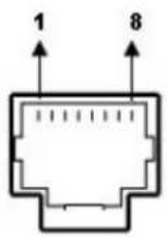
Pin Signal
1 TxD+
2 TxD-
3 RxD+
6 RxD-
PS/2 Mouse/Keyboard Port
Mouse/Keyboard connector
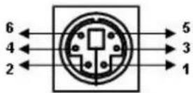
Pin Signal
1 Mouse / KBD data
2 NC
3 GND
Pin Signal
4 VCC
5 Mouse / KBD Clock
6 NC
Audio Port
Line Out/Mic ports.
Standard audio jacks.
USB Port 2.0
4-pin series-A receptacle. 6 ports.
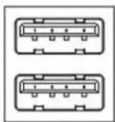
Pin Signal
1 VCC
2 D-
3 D+
4 GND