IS-IP220 - Security Camera Sentry360 - Free user manual and instructions
Find the device manual for free IS-IP220 Sentry360 in PDF.


User questions about IS-IP220 Sentry360
0 question about this device. Answer the ones you know or ask your own.
Ask a new question about this device
Download the instructions for your Security Camera in PDF format for free! Find your manual IS-IP220 - Sentry360 and take your electronic device back in hand. On this page are published all the documents necessary for the use of your device. IS-IP220 by Sentry360.
USER MANUAL IS-IP220 Sentry360
IS-IP200-IRB/IS-IP220-IRB-30
Detailed
Feature
Users
Manual
Ver1.5
00P9NHXX3ZXSEA5
TableofContents
- Overview....3
- Menu Tree....3
2.1 Home Page....4
2.1.1 Function Items on Home Page
2.1.2 Function Differences between Models....8
2.2 System 9
2.2.1 System....9
2.2.2 Security....10
2.2.2.1 User 10
2.2.2.2 HTTPS 12
2.2.2.3 IP Filter 14
2.2.2.4 IEEE 802.1X....15
2.2.3 Network.... 16
2.2.3.1 Basic.... 16
2.2.3.2 QoS 18
2.2.3.3 SNMP 19
2.2.3.4 UPnP 20
2.2.4 DDNS 21
2.2.5 Mail 21
2.2.6 FTP 22
2.2.7 HTTP....22
2.2.8 Application (Compact Fixed Dome Excluded)....23
2.2.9 Motion Detection 27
2.2.10 Network Failure Detection 32
2.2.11 Tampering....34
2.2.12 Storage Management (Local Recording) 38
2.2.13 Recording (Local Recording)....40
2.2.14 File Location (Snapshots and Web Recording)....41
2.2.15 Fisheye Setting (For Fisheye Camera Only)....41
2.2.16 Iris Adjustment (Fixed Focal Lens Excluded)....42
2.2.17 View Information....43
2.2.17.1 Log File....43
2.2.17.2 User Information 43
2.2.17.3 Parameters....44
2.2.18 Factory Default....44
2.2.19 Software Version....44
2.2.20 Software Upgrade 45
2.2.21 Maintenance....46
2.3 Streaming....47
2.3.1 Video Format (Video Resolution and Rotate Type)......47
2.3.2 Video Compression....49
2.3.3 Video ROI....50
2.3.4 Video OCX Protocol 51
2.3.5 Video Frame Rate 51
2.3.6 Video Mask 52
2.3.7 Audio (Audio Mode and Bit Rate Settings)....53
2.4 Cam era....54
2.4.1 Exposure Setting....54
2.4.2 White Balance Setting....55
2.4.3 Picture Adjustment....56
2.4.4 Backlight 56
2.4.5 Digital Zoom 57
2.4.6 IR Function (Compact Fixed Dome Excluded)....57
2.4.7 WDR Function....58
2.4.8 Noise Reduction....58
2.4.9 TV System Setting....58
2.5 Pan Tilt 59
2.5.1 Preset....59
2.5.2 Sequence
2.5.3 Pan/Tilt Control 61
2.6 Logout 61
Appendix A: Install UPnP Components....62
60
1. Overview
The IS-IP200-IRB is a dynamic, easy to use megapixel surveillance camera that is compatible with the leading VMS partners found http://www.sentry360.com/partners/technology-partners and Sentry360's own free NVR software sentryCore. In this manual, information about main page introduction, system related settings and camera settings will be described.
2. Menu Tree
There are six main tabs including
Home
Users can monitor live video of the targeted area.
Systemsetting
The administrator can set host name, system time, root password, network related settings, etc. Further details will be interpreted in chapter System.
Streaming setting
The administrator can modify video resolution and rotate type and select audio compression mode in this page.
Camerasetting
Users can adjust various camera parameters, including
PanTiltsetting
Users can activate the pan/ tilt function and select the RS-485 protocol which the Pan Tilt Head uses in the

NOTE: Pan Tilt function is only available for 10x/ 18x Zoom AF IS-IP200-IRB/IS-IP220-IRB-30 and Box Camera. (DC12V/ AC24V/PoE Model)
Logout
Click on the tab to re-login the IP Camera with another username and password.
2.1 Home Page
Click on the tab
2.1.1 Function Items on Home Page
MultipleLanguagesSupport
Multiple languages are supported, including German, English, French, Italian, Korean, Simplified Chinese, Traditional Chinese, Russian, etc. for the viewer window interface.
DigitalZoomControl
In the full screen mode, users can implement digital PTZ by rotating the mouse wheel (for zoom in/ out), and drag the mouse into any direction.
ScreenSizeAdjustment

Image display size can be adjusted to x1/2 and full screen.
Talkbutton

Talk function allows the local site to talk to the remote site. Click on the button to switch it to on/off. Please refer to Security: Add user > Talk/Listen for further details. This function is only open to "User" who has been granted this privilege by the Administrator.
Speakerbutton

Click on the

NOTE: This function is only available for User who has granted this privilege by the Administrator.
Snapshotbutton

Click on the button and the JPEG snapshots will automatically be saved in the appointed place. The default place of saving snapshots is: C:. To change the storage location, please refer to FileLocation for further details.

NOTE: For users with Windows 7 operating system, it is required to log on as an Administrator to implement the Snapshot function.
VideoStreamingPause/Restartbutton
(pause/restart)
Click on the
WebRecordingbutton

Click on the

NOTE: For users with Windows 7 operating system, it is required to log on as an Administrator to implement the Web Recording function.
ZoomAdjustment
- Tele/Wide buttons
Wide Tele
Hold the
• Tele/Wide Steps buttons
Tele Steps Wide Steps
Click on the
Manual FocusAdjustment
- Manual button
Manual
Click on the
- Near/Far buttons
Near Far
Hold the
• Near/Far Steps buttons
Near Steps Far Steps
Click on the
AutoFocus(AF) Adjustment
The AF mode can be defined as of automatic, zoom triggered and one-push.
- Auto (Continuous AF) Auto In this mode, the camera will keep in focus automatically and continuously regardless of zoom changes or any view changes.
- Zoom AF (Zoom Trigger AF) Zoom AF In this mode, AF is activated at the time when zoom is adjusted.
- Push AF Push AF The one-push AF function is for fixing the focus on the target in a shot using AF. Once click on the button, AF will be implemented.
- Reset button Reset
Click on the
button, and the camera lens will be calibrated at full wide end and infinity focus at once.
Fisheyelmage Adjustment (For Fisheye Camera Only)
- Fisheye Source Image
Click on the
button, and the live video will be shown as circular Fisheye Source Image. - Single ePTZ
Click on the
button to virtually pan/ tilt/ zoom the Camera according to users needs. Users can implement virtual PTZ by rotating the mouse wheel (for zoom in/ out), and drag the mouse into any direction. - 360° Panoramic Click on the <360° Panoramic> button to view the live video as two 180° views in the Live Video Pane.
- Quad View Click on the
button to view the live video as four ePTZ views. - 180° Panoramic Click on the <180° Panoramic> button to view the live video as a single 180° view.
- Dual ePTZ

For Wall Mount Installed Camera, click on the

NOTE: Please note that the function items are varied from model to model, refer to the following chapter: Function Differences between Models for more detail.
2.1.2 Function Differences between Models
Below table tells the model differences you will find on the home page. “√” indicates functions can be found on the model you bought. “A-F” each indicates a model type, “a-b” indicate different lens as shown below:
A. Full HD Multiple Streams Box IS-IP200-IRB/IS-IP220-IRB-30
B. 10x/18x Zoom AF IS-IP200-IRB/IS-IP220-IRB-30
C. Full HD Multiple Streams Vandal Proof Fixed Dome IS-IP200-
IRB/IS-IP220-IRB-30 D. Full HD Multiple Streams Lightweight
Fixed Dome IS-IP200-IRB/IS-IP220-IRB-30 E. Full HD Multiple
Streams IR Bullet IS-IP200-IRB/IS-IP220-IRB-30
F.Full HD Multiple Streams Compact Fixed Dome IS-IP200-IRB/IS-IP220-IRB-30
G. Fisheye IS-IP200-IRB/IS-IP220-IRB-30
(*) a. Vari-focal Lens; b. Motorized Lens; c. Fixed-focal Lens; d. Wall Mount Installed; e. Ceiling Installed
| Function\Model | A | B | C D | E | F | G | |||||||
| a | b | a | b | a | b | c | d | e | |||||
| Multiple Language | √ | √ √ | √ | √ √ | √ | √ √ | √ √ | √ | |||||
| Digital Zoom Control | √ | √ | √ | √ | √ | √ | √ | √ | √ | √ | - | - | |
| Screen Size Adjustment | √ | √ √ | √ | √ √ | √ | √ | √ √ √ | √ | |||||
| Talk (On/Off) | √ | √ | √ | √ | √ | √ | √ | √ | - | - | √ | √ | |
| Speaker (On/Off) | √ | √ √ | √ | √ √ | √ | √ √ | √ √ | √ | |||||
| Snapshot | √ | √ √ | √ | √ √ | √ | √ √ | √ √ | √ | |||||
| Video Streaming Pause/ Restart | √ | √ | √ | √ | √ | √ | √ | √ | √ | √ | √ | √ | |
| Web Recording (On/Off) | √ | √ √ | √ | √ √ | √ | √ | √ √ √ | √ | |||||
| Zoom Adjustment | Tele/ Wide | - | √ | - | √ | - | √ | - | √ | - | - | - | - |
| Tele Steps / Wide Steps | - | - | - | √ | - | √ | - | √ | - | - | - | - | |
| Reset | - | - | - | √ | - | √ | - | √ | - | - | - | - | |
| Manual Focus Adjustment | Manual | - | √ | - | - | - | - | - | - | - | - | - | - |
| Near/ Far | - | √ | - | √ | - | √ | - | √ | - | - | - | - | |
| Near Steps/ Far Steps | - | - | - | √ | - | √ | - | √ | - | - | - | - | |
| Reset | - | - | - | √ | - | √ | - | √ | - | - | - | - | |
| Auto Focus Adjustment | Auto | - | √ | - | - | - | - | - | - | - | - | - | - |
| Zoom AF | - | √ | - | - | - | - | - | - | - | - | - | - | |
| Push AF | - | √ | - | √ | - | √ | - | √ | - | - | - | - | |
| Fisheye Source Image | - | - | - | - | - | - | - | - | - | - | √ | √ | |
| Dual ePTZ | - | - | - | - | - | - | - | - | - | - | √ | - | |
| 180° Panoramic | - | - | - | - | - | - | - | - | - | - | √ | - | |
| Single ePTZ | - | - | - | - | - | - | - | - | - | - | - | √ | |
| 360° Panoramic | - | - | - | - | - | - | - | - | - | - | - | √ | |
| Quad View | - | - | - | - | - | - | - | - | - | - | - | √ | |
2.2 System
Under the tab

NOTE: The System configuration page is only accessible by the Administrator.
2.2.1 System
The System Setting can be found under the path: System> System.
HostName
The name is for camera identification. If alarm function (refer to Application) is enabled and is set to send alarm message by Mail/FTP, the host name entered here will display in the alarm message. The maximum length of the Host Name is 30 characters.
TimeZone
Select the time zone you are in from the drop-down menu.
EnableDaylightSavingTime
To enable DST, please check the item and then specify time offset and DST duration. The format for time offset is [hh:mm:ss]; for instance, if the amount of time offset is one hour, please enter "01:00:00" into the field.
SyncWithComputerTime
Select the item, and video date and time display will synchronize with the PC's.
Manual
The Administrator can set video date, time and day manually. Entry format should be identical with that shown next to the enter fields.
SyncwithNTPserver
Network Time Protocol (NTP) is an alternate way to synchronize your camera's clock with a NTP server. Please specify the server you wish to synchronize in the enter field. Then select an update interval from the drop-down menu. For further information about NTP, please refer to the web site: www.ntp.org.
2.2.2 Security
The Security setting can be found under this path: System> Security.
Click on the Security category, there will be a drop-down menu with tabs including
2.2.2.1 User
The User setting can be found under this path: System> Security> User.
Admin Password
Change the administrator's password by inputting the new password in "Admin password" and "Confirm password" text boxes. The input characters/numbers will be displayed as dots for security purposes. After clicking on

NOTE: The following characters are valid: A-Z, a-z, 0-9, !#\$%&'-.@^\~.
Adduser
Type the new user's name and password and click on
•I/O access
This item supports fundamental functions that enable users to view video when accessing to the camera.
- Camera control
This item allows the appointed User to change camera parameters on the Camera Setting page.
•Talk/Listen
Talk and Listen functions allow the appointed user in the local site (PC site) communicating with, for instance, the administrator in the remote site.
ManageUser
- Delete user
To delete a user, pull down the user list, and select the user name you wish to delete. Then click on
- Edit user
Pull down the user list and select a user name. Click on

NOTE: It is required to enter the User password as well as check the function items which will be available for the user. When finished, click on
2.2.2.2 HTTPS
The HTTPS setting can be found under this path: System> Security> HTTPS.
To use HTTPS on the IS-IP200-IRB/IS-IP220-IRB-30, a HTTPS certificate must be installed. The HTTPS certificate can be obtained by either creating and sending a certificate request to a Certificate Authority (CA) or creating a self-signed HTTPS certificate, as described below.
CreateSelf-signedCertificate
Before a CA-issued certificate is obtained, users can create and install a self-signed certificate first.
Click on

NOTE: The self-signed certificate does not provide the same high level of security as when using a CA-issued certificate.
InstallSignedCertificate
Click on the
Provide the request information in the create dialog. Please refer to the following ProvidetheCertificateInformation for more details.
When the request is complete, the subject of the Created Request will be shown in the field. Click on
When the signed certificate is returned, install it by uploading the signed certificate.
ProvidetheCertificateInformation
To create a Self-signed HTTPS Certificate or a Certificate Request to CA, please enter the information as requested:
| Create Self Signed Certificate | Create Certificate | Request | |
| Country | √ | √ | |
| State or Province | √ | √ | |
| Locality | √ | √ | |
| Organization | √ | √ | |
| OrganizationalUnit | √ | √ | |
| Common Name | √ | √ | |
| Valid Day | √ | - |
•Country
Enter a 2-letter combination code to indicate the country the certificate will be used in. For instance, type in "US" to indicate United States.
• State or province
Enter the local administrative region.
- Locality
Enter other geographical information.
- Organization
Enter the name of the organization to which the entity identified in "Common Name" belongs.
- Organization Unit
Enter the name of the organizational unit to which the entity identified in "Common Name" belongs.
- Common Name
Indicate the name of the person or other entity that the certificate identifies (often used to identify the website).
- Valid days
Enter the period in days (1\~9999) to indicate the valid period of certificate.
Click on
2.2.2.3 IP Filter
The IP Filter setting can be found under this path: System> Security> IP Filter.
Using the IP filter, access to the IP Camera can be restricted by denying/allowing specific IP addresses.
- Enable IP Filter
Check the box to enable the IP Filter function. Once enabled, the listed IP addresses (IPv4) will be allowed/ denied access to the IS-IP200-IRB/IS-IP220-IRB-30.
Select
- Add/ Delete IP Address
Input the IP address and click on the
The Filtered IP Addresses list box shows the currently configured IP addresses. Up to 256 IP address entries may be specified.
To remove an IP address from the list, please select the IP and then click on the
2.2.2.4 IEEE 802.1X
The IEEE 802.1X setting can be found under this path: System> Security> IEEE 802.1X.
The IS-IP200-IRB/IS-IP220-IRB-30 is allowed to access a network protected by 802.1X/EAPOL (Extensible Authentication Protocol over LAN).
Users need to contact with the network administrator for gaining certificates, user IDs and passwords
CACertificate
The CA certificate is created by the Certification Authority for the purpose of validating itself. Upload the certificate for checking the server's identity.
ClientCertificate/PrivateKey
Upload the Client Certificate and Private Key for authenticating the IS-IP200-IRB/IS-IP220-IRB-30 itself.
Settings
•Identity
Enter the user identity associated with the certificate. Up to 16 characters can be used.
- Private Key Password
Enter the password (maximum 16 characters) for your user identity.
EnableIEEE802.1X
Check the box to enable IEEE 802.1X.
Click on
2.2.3 Network
The Network setting can be found under this path: System> Network.
Click on the
2.2.3.1 Basic
The Basic setting can be found under this path: System> Network> Basic.
Users can choose to connect to the IS-IP200-IRB/IS-IP220-IRB-30 with fixed or dynamic (DHCP) IP address. The IS-IP200-IRB/IS-IP220-IRB-30 also provides PPPoE support for users who connect to the network via PPP over Ethernet (PPPoE).
General
• Get IP address automatically (DHCP)
The camera's default setting is
If select

NOTE: Please make the record of the IP Camera's MAC address, which can be found in the label of the camera, for identification in the future.
• Use fixed IP address
To setup static IP address, select
When using static IP address to login to the IS-IP200-IRB/IS-IP220-IRB-30, users can access it either through "DeviceSearch" software (refer to User's Manual) or input the IP address in the URL bar and click on
IP address
This is necessary for network identification.
Subnet mask
It is used to determine if the destination is in the same subnet. The default value is "255.255.255.0".
Default gateway
This is the gateway used to forward frames to destinations in different subnet. Invalid gateway setting will fail the transmission to destinations in different subnet.
Primary DNS
Primary DNS is the primary domain name server that translates hostnames into IP addresses.
Secondary DNS
Secondary DNS is a secondary domain name server that backups the primary DNS.
UsePPPoE
For the PPPoE users, enter the PPPoE Username and Password into the fields, and click on the
Advanced
- Web Server port
The default web server port is 80. Once the port is changed, the user must be notified the change for the connection to be successful. For instance, when the Administrator changes the HTTP port of the IS-IP200-IRB/IS-IP220-IRB-30 whose IP address is 192.168.0.100 from 80 to 8080, the user must type in the web browser "http://192.168.0.100:8080" instead of "http://192.168.0.100".
•RTSP port
The default setting of RTSP Port is 554; the setting range is from 1024 to 65535.
- MJPEG over HTTP port
The default setting of MJPEG over HTTP Port is 8008; the setting range is from 1024 to 65535.
- HTTPS port
The default setting of HTTPS Port is 443; the setting range is from 1024 to 65535.

NOTE: Be aware to choose the different port from the one set for the web server port.
IPv6AddressConfiguration
With IPv6 support, users can use the corresponding IPv6 address for browsing. Enable IPv6 by checking the box and click on
2.2.3.2 QoS
The QoS (Quality of Service) setting can be found under this path: System> Network> QoS.
QoS allows providing differentiated service levels for different types of traffic packets, which guarantees delivery of priority services especially when network congestion occurs. Adapting the Differentiated Services (DiffServ) model, traffic flows are classified and marked with DSCP (DiffServ Codepoint) values, and thus receive the corresponding forwarding treatment from DiffServ capable routers.
DSCPSettings
The DSCP value range is from 0 to 63. The default DSCP value is 0, which means DSCP is disabled. The IS-IP200-IRB/IS-IP220-IRB-30 uses the following QoS Classes: Video, Audio and Management.
•Video DSCP
The class consists of applications such as MJPEG over HTTP, RTP/RTSP and RTSP/HTTP.
•Audio DSCP
This setting is only available for the IS-IP200-IRB/IS-IP220-IRB-30s that support audio.
•Management DSCP
The class consists of HTTP traffic: Web browsing.

NOTE: To enable this function, please make sure the switches/ routers in the network support QoS.
2.2.3.3 SNMP
The SNMP (Simple Network Management Protocol) setting can be found under this path: System> Network> SNMP.
With Simple Network Management Protocol (SNMP) support, the IS-IP200-IRB/IS-IP220-IRB-30 can be monitored and managed remotely by the network management system.
SNMPv1/v2
- Enable SNMP v1/ v2
Select the version of SNMP to use by checking the box.
- Read Community
Specify the community name that has read-only access to all supported SNMP objects. The default value is "public".
- Write Community
Specify the community name that has read/write access to all supported SNMP objects (except read-only objects). The default value is "write".
Traps for SNMP v1/v2
Traps are used by the IS-IP200-IRB/IS-IP220-IRB-30 to send massages to a management system for important events or status changes.
- Enable Traps
Check the box to activate trap reporting.
- Trap address
Enter the IP address of the management server.
- Trap community
Enter the community to use when sending a trap message to the management system.
TrapOption
•Warm Start
A Warm Start SNMP trap signifies that the SNMP device, i.e. IS-IP200-IRB/IS-IP220-IRB-30, performs software reload.
Click on
2.2.3.4 UPnP
The UPnP setting can be found under this path: System> Network> UPnP.
UPnPSetting
- Enable UPnP
When the UPnP is enabled, whenever the IS-IP200-IRB/IS-IP220-IRB-30 is presented to the LAN, the icon of the connected IS-IP200-IRB/IS-IP220-IRB-30s will appear in My Network Places to allow for direct access.

NOTE: To enable this function, please make sure the UPnP component is installed on your computer. Please refer to Install UPnPcomponents for UPnP component installation procedure.
- Enable UPnP port forwarding
When the UPnP port forwarding is enabled, the IS-IP200-IRB/IS-IP220-IRB-30 is allowed to open the web server port on the router automatically.

NOTE: To enable this function, please make sure that your router supports UPnP and it is activated.
- Friendly name
Set the name for the IS-IP200-IRB/IS-IP220-IRB-30 for identity.
2.2.4 DDNS
The DDNS setting can be found under this path: System> DDNS.
Dynamic Domain Name System (DDNS) allows a host name to be constantly synchronized with a dynamic IP address. In other words, it allows those using a dynamic IP address to be associated to a static domain name so others can connect to it by name.
EnableDDNS
Check the item to enable DDNS.
Provider
Select one DDNS host from the provider list.
Hostname
Enter the registered domain name in the field.
Username/E-mail
Enter the username or e-mail required by the DDNS provider for authentication.
Password/Key
Enter the password or key required by the DDNS provider for authentication.
2.2.5 Mail
The Mail setting can be found under this path: System> Mail.
The Administrator can send an e-mail via Simple Mail Transfer Protocol (SMTP) when event is triggered. SMTP is a protocol for sending e-mail messages between servers. SMTP is a relatively simple, text-based protocol, where one or more recipients of a message are specified and the message text is transferred.
Two sets of SMTP can be configured. Each set includes SMTP Server, Server Port, Account Name, Password and E-mail Address settings. Check the box "SMTP SSL" to send emails via encrypted transmission. For SMTP server, contact your network service provider for more specific information.
2.2.6 FTP
The FTP setting can be found under this path: System> FTP.
The Administrator can set as sending alarm message to a specific File Transfer Protocol (FTP) site when event is triggered. Users can assign alarm message to up to two FTP sites. Enter the FTP details, which include server, server port, user name, password and remote folder, in the fields. Check the box “passive mode” to be connected with the FTP server by passively receiving the FTP server’s IP address through a dynamic port. Alternatively, uncheck the box to directly connect the FTP server via active mode.
Click on
2.2.7 HTTP
The HTTP setting can be found under this path: System> HTTP.
A HTTP Notification server can listen for notification messages from IS-IP200-IRB/IS-IP220-IRB-30s by triggered events. Enter the HTTP details, which include server name (for instance, http://192.168.0.1/admin.php), user name, and password in the fields.
Click on

Please refer to: Application>SendHTTPnotification/MotionDetection for HTTP Notification settings.
2.2.8 Application (Compact Fixed Dome Excluded)
The Application setting can be found under this path: System> Application.
The IS-IP200-IRB/IS-IP220-IRB-30 equips one alarm input and one relay output for cooperating with alarm system to catch events' images. Refer to alarm pin definition below to connect alarm devices to the IS-IP200-IRB/IS-IP220-IRB-30 if needed.
AlarmPin Definition
Please refer to User's Manual for Alarm Pin Definition to connect the alarm devices.
AlarmSwitch
The Administrator can enable or disable the alarm function.
AlarmType
Select an alarm type,
AlarmOutput
Define alarm output signal
TriggeredAction (Multi-option)
The Administrator can specify alarm actions that will take when the alarm is triggered. All options are listed as follows:
- Enable Alarm Output
Select the item to enable alarm relay output.
- IR Cut Filter
Select the item and the camera's IR cut filter (ICR) will be removed (on) or blocked (off) when alarm input is triggered.

Note: The IR Function (Refer to IRFunction) could not be set as
- Send Message by FTP/E-Mail
The Administrator can select whether to send an alarm message by FTP
and/or E-Mail when an alarm is triggered.
- Upload Image by FTP
Select this item and the Administrator can assign a FTP site and configure various parameters. When the alarm is triggered, event images will be uploaded to the appointed FTP site.
On the other hand,
Check the box

NOTE: Make sure FTP configuration has been completed. Refer to FTP for further details.
- Upload Image by E-Mail
Select this item and the Administrator can assign an e-mail address and configure various parameters. When the alarm input is triggered, event images will be sent to the appointed e-mail address.
On the other hand,
Check the box

NOTE: Make sure SMTP configuration has been completed. Refer to Mail for further details.
- Send HTTP notification
Check this item, select the destination HTTP address, and specify the parameters for event notifications by
For instance, if the custom parameter is set as" action=1&group=2", and the HTTP server name is" http://192.168.0.1/admin.php", the notification will be sent to HTTP server as" http://192.168.0.1/admin.php?action=1&group=2" when alarm is triggered.
• Record Stream to SD Card
Select the item and the alarm-triggered recording will be saved into your Micro SD card.
Pre-trigger buffer recording function allows users to check what happened to cause the trigger. The pre-trigger buffer time range is from 1 to 3 seconds.
Select
Select

NOTE: Please make sure the local recording (with Micro SD/SDHC card) is activated so that this function can be implemented. Refer to Recording for further details.
FileName
Enter a file name in the blank, ex. image.jpg. The uploaded image's file name format can be set in this section. Please select the one that meets your requirements.
- Add date/time suffix
File name: imageYYMMDD_HHNNSS_XX.jpg
Y: Year, M: Month, D: Day
H: Hour, N: Minute, S: Second
X: Sequence Number
- Add sequence number suffix (no maximum value)
File name: imageXXXXXXXX.jpg
X: Sequence Number
- Add sequence number suffix up to # and then start over
File Name: imageXX.jpg
X: Sequence Number
The file name suffix will end at the number being set. For example, if the setting is up to "10," the file name will start from 00, end at 10, and then start all over again.
•Overwrite
The original image in the FTP site will be overwritten by the new uploaded file with a static filename.
Save
After complete all the settings mentions above, please click on
2.2.9 Motion Detection
The Motion Detection setting can be found under this path: System> Motion Detection.
Motion Detection function allows detecting suspicious motion and triggering alarms when motion volume in the detected area reaches/exceeds the determined sensitivity threshold value.
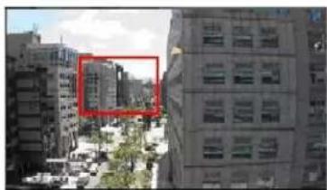
In the Motion Detection setting page, there is a frame (Motion Detection Window) displayed on the Live Video Pane as the figure below. The Motion Detection Window is for defining the motion detection area. To change the size of the Motion Detection Window, move the mouse cursor to the edge of the frame and draw it outward/inward. Moving the mouse to the center of the frame can shift the frame to the intended location.
natural_image
Exterior view of a multi-story building complex with trees and adjacent urban landscape (no visible text or signage)Up 10 Motion Detection Windows can be set. Click on the
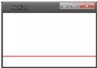
If Motion Detection function is activated, the pop-off window (Motion) with indication of motion will be shown.
text_image
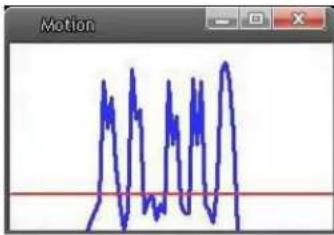
MotionWhen motion is detected, the signals will be displayed on the Motion window as shown below.
text_image
MotionMotion Detection
Users are able to turn on/off Motion Detection. Default setting is Off.
Motion DetectionSetting
Users could adjust various parameters of Motion Detection in this section.
• Sampling pixel interval [1-10]:
The default value is 1. If the value is set as 3, it means within the detection region, system will take one sampling pixel for every 3 pixels by each row and each column (refer to the figure below).
![Sentry360 IS-IP220 - • Sampling pixel interval [1-10]: - 1](/content/2026/05/819273/images/8ffb746599ab13c0a90570df365758484f2ede56ae12202fbb4122aea6d0acd1.jpg)
natural_image
Checkerboard pattern with alternating red and white squares (no text or symbols)• Detection level [1-100]:
The default level is 10. The item is to set detection level for each sampling pixel; the smaller the value, the more sensitive it is.
• Sensitivity level [1-100]:
The default level is 80, which means if 20% or more sampling pixels are detected differently, system will detect motion. The bigger the value, the more sensitive it is. Meanwhile, when the value is bigger, the red horizontal line in the motion indication window will be lower accordingly.
• Time interval (sec) [0-7200]:
The default interval is 10. The value is the interval between each detected motion.
TriggeredAction (Multi-option)
The Administrator can specify alarm actions that will take when motion is detected. All options are listed as follows:
- Enable Alarm Output
Check the item and select the predefined type of alarm output to enable alarm relay output when motion is detected.
• Record stream to SD Card
Select this item and the Motion Detection recording will be stored in Micro SD/ SDHC card when motion is detected.
Pre-trigger buffer recording function allows users to check what happened to cause the trigger. The pre-trigger buffer time range is from 1 to 3 seconds.
Select
Select

NOTE: Please make sure the local recording (with Micro SD/SDHC card) is activated so that this function can be implemented. Refer to Recording for further details.
- Send Alarm Message by FTP/E-Mail
The Administrator can select whether to send warning messages by FTP and/or E-Mail when motion is detected.
- Upload Image by FTP
Select this item and the Administrator can assign a FTP site and configure various parameters. When motion is detected, event images will be uploaded to the appointed FTP site.
On the other hand,
Check the box

NOTE: Make sure FTP configuration has been completed. Refer to FTP for further details.
- Upload Image by E-Mail
Select this item and the Administrator can assign an e-mail address and configure various parameters. When motion is detected, event images will be sent to the appointed e-mail address.
On the other hand,
Check the box

NOTE: Make sure SMTP configuration has been completed. Refer to Mail for further details.
- Send HTTP notification
Check this item, select the destination HTTP address, and specify the parameters for event notifications by
For instance, if the custom parameter is set as" action=1&group=2", and the HTTP server name is" http://192.168.0.1/admin.php", the notification will be sent to HTTP server as" http://192.168.0.1/admin.php?action=1&group=2" when alarm is triggered.
FileName
Enter a file name in the blank, ex. image.jpg. The uploaded image's file name format can be set in this section. Please select the one that meets your requirements.
- Add date/time suffix
File name: imageYYMMDD_HHNNSS_XX.jpg
Y: Year, M: Month, D: Day
H: Hour, N: Minute, S: Second
X: Sequence Number
- Add sequence number suffix (no maximum value)
File name: imageXXXXXXXX.jpg
X: Sequence Number
- Add sequence number suffix up to # and then start over
File Name: imageXX.jpg
X: Sequence Number
The file name suffix will end at the number being set. For example, if the setting is up to "10," the file name will start from 00, end at 10, and then start all over again.
•Overwrite
The original image in the FTP site will be overwritten by the new uploaded file with a static filename.
Save
Click on the
2.2.10 Network Failure Detection
Network Failure Detection allows the IS-IP200-IRB/IS-IP220-IRB-30 to ping another IP device (e.g. NVR, VSS, Video Server, etc.) within the network periodically and generates some actions in case of network failure occurs, for instance, a Video Server is somehow disconnected.
Being capable of implementing local recording (through Micro SD card) when network failure happens, the IS-IP200-IRB/IS-IP220-IRB-30 could be a backup recording device for the surveillance system.
DetectionSwitch
You will be able to turn on/off Network Failure Detection in System section. Default setting is Off.
DetectionType
Input the IP device address and the period of ping time to ping. The ping time setting range is from 1 to 99 minutes.
TriggeredAction (Multi-option)
The Administrator can specify alarm actions that will take when network failure is detected. All options are listed as follows:
- Enable Alarm Output
Select the item to enable alarm relay output.
• Record Stream to SD Card
Select the item and the alarm-triggered recording will be saved into your Micro SD card.
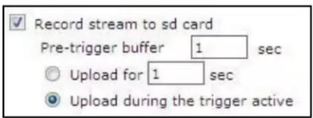
Pre-trigger buffer recording function allows users to check what happened to cause the trigger. The pre-trigger buffer time range is from 1 to 3 seconds. Select
text_image
Record stream to sd card Pre-trigger buffer 1 sec Upload for 1 sec Upload during the trigger active
NOTE: Please make sure the local recording (with Micro SD/SDHC card) is activated so that this function can be implemented. Refer to Recording for further details.
- Send Alarm Message by FTP/E-Mail
The Administrator can select whether to send an alarm message by FTP and/or E-Mail when an alarm is triggered.
Save
Click on the
2.2.11 Tampering
The Tampering setting can be found under this path: System>Tampering.
Tampering Alarm function helps the IS-IP200-IRB/IS-IP220-IRB-30 against tampering such as deliberate redirection, blocking, paint spray, and lens cover, etc through video analysis and reaction to such events by sending out notifications or uploading snapshots to the specified destination(s).
Detection of camera tampering is achieved by measuring the differences between the older frames of video (which are stored in buffers) and more recent frames.
TamperingAlarm
Users are able to turn on/off Tampering Alarm function in Tampering Alarm setting page. The default setting is Off.
TamperingDuration
Minimum Tampering Duration is the time for video analysis to determine whether camera tampering has occurred. Minimum Duration could also be interpreted as defining the Tampering threshold; longer duration represents higher threshold. Settable Tampering Duration time range is from 10 to 3600 seconds. The Default value is 20 seconds.
TriggeredAction (Multi-option)
The Administrator can specify alarm actions that will take when tampering is detected. All options are listed as follows:
- Enable Alarm Output
Check the item and select the predefined type of alarm output to enable alarm output when tampering is detected.
• Record stream to SD Card
Select this item and the Tampering Alarm recording will be stored in Micro SD/ SDHC card when tampering is detected.
Pre-trigger buffer recording function allows users to check what happened to cause the trigger. The pre-trigger buffer time range is from 1 to 3 seconds.
Select
Select

NOTE: Please make sure the local recording (with Micro SD/SDHC card) is activated so that this function can be implemented. Refer to Recording for further details.
- Send Message by FTP/E-Mail
The Administrator can select whether to send an alarm message by FTP and/or E-Mail when tampering is detected.
- Upload Image by FTP
Select this item and the Administrator can assign a FTP site and configure various parameters. When tampering is detected, event images will be uploaded to the appointed FTP site.
On the other hand,
Check the box

NOTE: Make sure FTP configuration has been completed. Refer to FTP for further details.
- Upload Image by E-Mail
Select this item and the Administrator can assign an e-mail address and configure various parameters. When tampering is detected, event images will be sent to the appointed e-mail address.
On the other hand,
Check the box

NOTE: Make sure SMTP configuration has been completed.
Refer to Mail for further details.
- Send HTTP notification
Check this item, select the destination HTTP address, and specify the parameters for HTTP notifications. When the Tampering Alarm is triggered, the HTTP notifications can be sent to the specified HTTP server.
For instance, if the custom parameter is set as" action=1&group=2", and the HTTP server name is "http://192.168.0.1/admin.php", the notification will be sent to HTTP server as" http://192.168.0.1/admin.php?action=1&group=2" when alarm is triggered.
FileName
Enter a file name in the blank, ex. image.jpg. The uploaded image's file name format can be set in this section. Please select the one that meets your requirements.
- Add date/time suffix
File name: imageYYMMDD_HHNNSS_XX.jpg
Y: Year, M: Month, D: Day
H: Hour, N: Minute, S: Second
X: Sequence Number
- Add sequence number suffix (no maximum value)
File name: imageXXXXXXXX.jpg
X: Sequence Number
- Add sequence number suffix up to # and then start over
File Name: imageXX.jpg
X: Sequence Number
The file name suffix will end at the number being set. For example, if the setting is up to "10," the file name will start from 00, end at 10, and then start all over again.
•Overwrite
The original image in the FTP site will be overwritten by the new uploaded file with a static filename.
Save
Click on the
2.2.12 Storage Management (Local Recording)
The Storage Management setting can be found under this path: System>Storage Management.
Users can implement local recording to the Micro SD/SDHC card up to 32GB. This page shows the capacity information of the Micro SD card and a recording list with all the recording files saved on the memory card. Users can also format the SD card and implement automatic recording cleanup through the setting page.
To implement Micro SD card recording, please go to the

NOTE: Please format the Micro SD/SDHC card when using for the first time. Formatting will also be required when a memory card already being used on one camera and later transferred to another camera with different software platform.
Deviceinformation
When users insert the Micro SD/SDHC card, the card information such as the memory capacity and status will be shown at Device Information section.
For the memory card being successfully installed, its status shall be shown at
Devicesetting
Click on the
Diskcleanupsetting
Users can enable automatic recordings cleanup by specifying the time and storage limits
RecordingList
Each video file on the Micro SD/SDHC card will be listed in the Recording list as shown below. The maximum file size is 60 MB (60 MB per file).
When the recording mode is set as "Always" (consecutive recording) and the Micro SD/ SDHC card recording is also allowed to be enabled by events triggered, once events occur, the system will immediately implement events recording to the memory card. Then the IS-IP200-IRB/IS-IP220-IRB-30 will return to the regular recording mode after events recording.
- Remove
To remove a file, select the file first, and then click on the
- Sort
Click on the

NOTE: The capital letter A/M/R/T appears in the very beginning of name denotes the sort of the recording: A stands for Alarm; M stands for Motion; R stands for regular recording, and T stands for Tampering.
-Download
To open/download a video clip, select the file first, and then click on the
2.2.13 Recording (Local Recording)
The Recording setting can be found under this path: System> Recording.
In the Recording setting page, the Micro SD Card recording schedule supports up to ten sets of time frames. User can specify the recording schedule to fit the present surveillance requirement.
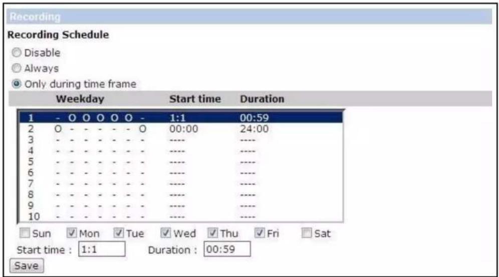
text_image
Recording Recording Schedule Disable Always Only during time frame Weekday Start time Duration 1 - 0 0 0 0 0 0 - 1:1 00:59 2 0 - - - - - - 0 00:00 24:00 3 - - - - - - - - ---- ---- 4 - - - - - - - - ---- ---- 5 - - - - - - - - ---- ---- 6 - - - - - - - - - ---- ---- 7 - - - - - - - - - ---- ---- 8 - - - - - - - - - ---- ---- 9 - - - - - - - - - ---- ---- 10 - - - - - - - - ---- ---- Sun Mon Tue Wed Thu Fri Sat Start time : 1:1 Duration : 00:59 SaveActivatingMicroSD/SDHCCardRecording
Two types of schedule mode are offered:
TerminatingMicroSD/SDHCCardRecording
Select
2.2.14 File Location (Snapshots and Web Recording)
The File Location setting can be found under this path: System> File Location.
Users can specify a storage location on the PC or in the hard drive for the snapshots and live video recording. The default setting is: C:. Once confirm the setting, click on

NOTE: Please make sure the selected file path contains valid characters such as letters and numbers.

NOTE: For users with Windows 7 operating system, it is required to log on as an Administrator to implement the Snapshot and Web Recording function.
2.2.15 Fisheye Setting (For Fisheye Camera Only)
The Fisheye setting can be found under this path: System> Fisheye Setting.
Users can setup the Camera's installation type to apply different dewarping methods, and calibrate the image dewarping via Horizontal Calibration when installing the Camera by Wall Mount.
Installation
There are different dewarping methods according to the installation of the Camera. Please select
HorizontalCalibration
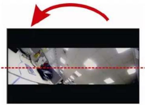
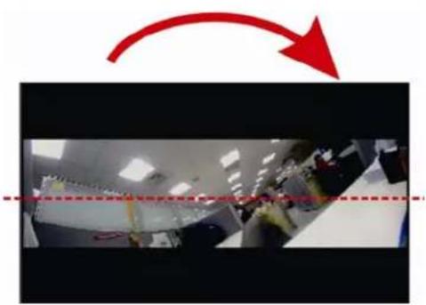
When installing Camera with Wall Mount, users might need to calibrate the image counterclockwise/ clockwise.
- Counterclockwise
With image as below, users can click on the <1> or <10> button to calibrate the image counterclockwise one degree or ten degrees.
natural_image
Interior view of a room with ceiling lights and a red arrow indicating rotation (no text or symbols)- Clockwise
With image as below, users can click on the <1> or <10> button to calibrate the image clockwise one degree or ten degrees.
natural_image
Interior view of a garment factory with workers at sewing stations and a red arrow indicating rotation (no text or symbols)2.2.16 Iris Adjustment (Fixed Focal Lens Excluded)
The Iris Adjustment function can be found under this path: System> Iris Adjustment.
For users who use Auto-iris lens, when it is required to implement iris adjustment, please refer to the Iris adjustment procedure in the setting page to adjust iris.
2.2.17 View Information
The View Information function can be found under this path: System> View Information.
Click on the category:
2.2.17.1 Log File
The Log File function can be found under this path: System> Log File.
Click on the tab to view the system log file. The content of the file provides useful information about connections after system boot-up.
2.2.17.2 User Information
The User Information function can be found under this path: System> User Information.
The Administrator can view each added user's login information and privileges (refer to Security).
GetUserInformation
All the users in the network will be listed in the
User: 4321
It indicates that one user's login username is "User", and the password is "4321".
GetUserPrivacy
Click on
User: 1:1:0:1
1:1:0:1= I/O access : Camera control : Talk : Listen (refer to Security)
Therefore, it denotes the user is granted privileges of I/O access, Camera control and Listen.
2.2.17.3 Parameters
.The Parameters function can be found under this path: System> Parameter.
Click on this item to view the entire system's parameter setting such as Camera Settings, Mask Information and Network Information.
2.2.18 Factory Default
The Factory Default setting can be found under this path: System> Factory Default.
Users can follow the instructions on this page to reset the IS-IP200-IRB/IS-IP220-IRB-30 to factory default setting if needed.
SetDefault
Click on the

NOTE: The IP address will be restored to default.
Reboot
Click on the
2.2.19 Software Version
The Software Version can be found under this path: System> Software Version.
The current software version is displayed in the software version page.
2.2.20 Software Upgrade
The Software Upgrade setting can be found under this path: System> Software Upgrade.

NOTE: Make sure the upgrade software file is available before carrying out software upgrade.
The procedure of software upgrade is as below:
Step 1. Click on "Browse" and select the binary file to be uploaded, ex. ulmage_userland.

NOTE: Do not change the upgrade file name, or the system will fail to find the file.
Step 2. Pull down the upgrade binary file list and select the file "ulmage+userland.img"
Step 3. Click on the
After the upgrade process is finished, the viewer will return to Home page.
Step 4. Close the video browser.
Step 5. Start
Step 6. Open a new web browser, re-login the IS-IP200-IRB/IS-IP220-IRB-30, and then allow the automatic download of DC Viewer.
2.2.21 Maintenance
The Maintenance setting can be found under this path: System> Maintenance.
Users can export configuration files to a specified location and retrieve data by uploading an existing configuration file to the IS-IP200-IRB/IS-IP220-IRB-30.
Export
Users can save the system settings by exporting the configuration file (.bin) to a specified location for future use. Click on the
Upload
To copy an existing configuration file to the IS-IP200-IRB/IS-IP220-IRB-30, please first click on
2.3 Streaming
Under the tab
In the Streaming submenus, the Administrator can configure specific video resolution, video compression mode, video protocol, audio transmission mode, etc. Further details of these settings will be specified in the following sections.
2.3.1 Video Format (Video Resolution and Rotate Type)
The Video Format setting can be found under this path: Streaming> Video Format.
VideoResolution
Under Video Resolution section, the available video resolution formats are including MJPEG and H.264. Please refer to the User's Manual for more combination details.
Click on
TextOverlaySettings
Users can select the items to display data including date/time/text on the live video pane. The maximum length of the string is 20 alphanumeric characters.
Click on
VideoRotateType
Users can change video display type if necessary. Selectable video rotate types include Normal, Flip, Mirror, 90 degree clockwise, 180 degree rotate and 90 degree counterclockwise.
The following is descriptions for different video rotate type.
•Flip
If select
•Mirror
If select
• 90 Degree counter-/clockwise
Selecting <90 Degree Counter-/clockwise> will make the image 90^ counter-/clockwise inversed.
• 180 Degree Rotate
Selecting <180 Degree> will make the image 180^ inversed.
Click on
GOVSettings
Users can set the GOV length to determine the frame structure (I-frames and P-frames) in a video stream for saving bandwidth. The setting range is from 2 to 64. Default value is 60, which means there's one I-frame every 60 frames. Longer GOV length means lower I-frame frequency. The default value for H.264-1/ H.264-2/ H.264-3/ H.264-4 is 60/ 60/ 30/ 30. Click on
H.264Profile
Users can set each H.264 Profile to

NOTE: Please make sure the higher compression ratio is supported by system before setup.
2.3.2 Video Compression
The Video Compression setting can be found under this path: Streaming>Video Compression.
Users can select a proper MJPEG/H.264 compression mode in the video compression page depending on the application.
MJPEGQ(Quality)factor
Higher value implies higher bit rates and higher visual quality. The default setting of MJPEG Q factor is 35; the setting range is from 1 to 70.
H.264-1/H.264-2/H.264-3/H.264-4bitrate
The default setting of H.264-1 is 4096 kbit/s and for H.264-2/ H.264-3/ H.264-4 is 1024 kbit/s; the setting range for H.264-1 is from 64 to 8192 kbps and for H.264-2/ H.264-3/ /H.264-4 is from 64 to 2048 kbit/s.
DisplayCompressionInformation
Users can also decide whether to display compression information on the Home page.
CBRModeSetting
The CBR (Constant Bit Rate) mode could be the preferred bit rate mode if the bandwidth available is limited. It is important to take account of image quality while choosing to use CBR mode.
Click on
2.3.3 Video ROI
The Video ROI setting can be found under this path: Streaming> Video ROI.
ROI stands for Region of Interest. This function allows users to select specific monitoring region for 2^nd , 3^rd and 4^th streams, instead of showing the full image.

NOTE: This function is only available when triple streams or above is selected under Video Resolution in Video Format Setting.
VideoROISetting
- Enable Stream 2 ROI Setting
Check the box and Stream 2 ROI Window will be displayed. To change the size of Stream 2 ROI Window, move the mouse cursor to the edge of the frame and draw it outward/inward. Moving the mouse to the center of the frame can shift the frame to the intended location.
- Enable Stream 3 ROI Setting
Check the box and Stream 3 ROI Window will be displayed. To change the size of Stream 3 ROI Window, move the mouse cursor to the edge of the frame and draw it outward/inward. Moving the mouse to the center of the frame can shift the frame to the intended location.
- Enable Stream 4 ROI Setting
Check the box and Stream 4 ROI Window will be displayed. To change the size of Stream 4 ROI Window, move the mouse cursor to the edge of the frame and draw it outward/inward. Moving the mouse to the center of the frame can shift the frame to the intended location.
2.3.4 Video OCX Protocol
The Video OCX Protocol setting can be found under this path: Streaming>Video OCX Protocol.
In the Video OCX protocol setting page, users can select RTP over UDP, RTP over RTSP (TCP), RTSP over HTTP or MJPEG over HTTP for streaming video over the network. In the case of multicast networking, users can select the Multicast mode. Click on
Video OCX protocol setting options include:
- RTP over UDP / RTP over RTSP(TCP) / RTSP over HTTP / MJPEG over HTTP
- Multicast Mode
Enter all required data, including
2.3.5 Video Frame Rate
The Video Frame Rate setting can be found under this path: Streaming> Video Frame Rate.
Video frame rate is for setting the frames per second (fps) if necessary.
MJPEG/H.264-1/H.264-2/H.264-3/H.264-4FrameRate
The default setting of MJPEG/H.264-1/H.264-2/ H.264-3/ H.264-4 Frame Rate is 30 fps; the setting range is from 1 to 30.
Click on

NOTE: Lower frame rate will decrease video smoothness.
2.3.6 Video Mask
The Video Mask setting can be found under this path: Streaming> Video Mask.
ActiveMaskFunction
- Add a Mask
Check a Video Mask checkbox, and a red frame will come out in the Live Video pane at the right side. Use the mouse to drag and drop to adjust the mask's size and place it on the target zone.

NOTE: It is suggested to set the Video Mask twice bigger than the object.
- Cancel a Mask
Uncheck the checkbox of the Video Mask meant to be deleted, and the selected mask will disappear from the Live Video pane instantly.
MaskSetting
- Mask color
The selections of Mask color include red, black, white, yellow, green, blue, cyan, and magenta. Click on
2.3.7 Audio (Audio Mode and Bit Rate Settings)
The Audio Mode setting can be found under this path: Streaming>Audio.
In the Audio page, the Administrator can select one transmission mode and audio bit rate.
TransmissionMode
• Full-duplex (Talk and Listen simultaneously)
In the Full-duplex mode, the local and remote sites can communicate with each other simultaneously, i.e. both sites can speak and be heard at the same time.
• Half-duplex (Talk or Listen, not at the same time)
In the Half-duplex mode, the local/remote site can only talk or listen to the other site at a time.
- Simplex (Talk only)
In the Talk only Simplex mode, the local/remote site can only talk to the other site.

NOTE: This function is not available for Compact Fixed Dome.
- Simplex (Listen only)
In the Listen only Simplex mode, the local/remote site can only listen to the other site.
-Disable
Select the item to turn off the audio transmission function.
ServerGainSetting
Set the audio input/output gain levels for sound amplification. The audio gain values are adjustable from 1 to 6. The sound will be turned off if the audio gain is set to "Mute".
BitRate
Selectable audio transmission bit rate include 16 kbps (G.726), 24 kbps (G.726), 32 kbps (G.726), 40 kbps (G.726), uLAW (G.711) and ALAW (G.711). Both uLAW and ALAW signify 64 kbps but in different compression formats. Higher bit rate will let higher audio quality and require bigger bandwidth. Click on
2.4 Camera
Under the tab
2.4.1 Exposure Setting
The Exposure Setting can be found under this path: Camera> Exposure.
The exposure is the amount of light received by the image sensor and is determined by the width of lens diaphragm opening, the amount of exposure by the sensor (shutter speed) and other exposure parameters. With this item, users can define how the Auto Exposure function works.
Each exposure mode is specified as follows:
AutoMode
• Auto Iris (Fixed Focal Lens Excluded)
In this mode, the exposure gives priority to the auto iris. The minimum shutter speed can be set from 1 (1/1.5) to 1/30 (1/25) sec. AGC (Auto Gain Control) will function automatically according to the light conditions of the subject.

NOTE: This function is not available for Fixed Focal Lens Models.
• Auto Shutter Mode
This function is to control the shutter speed and adjust the iris automatically according to the light intensity. It is also effective if a fixed iris lens is being used. The minimum shutter speed range is configurable from 1 (1/1.5) to 1/500 (1/425) sec.
- Shutter Priority Mode
This function is to set the shutter speed at a specified speed. The range is configurable from 1/30 (1/25) to 1/500 (1/425) sec.
Manual Mode
• Fixed Shutter Mode
In this mode, fixed shutter speed could be selected from the dropdown menu. The shutter speed range is from 1/10000 to 1 (1/1.5) sec. with 19 (18) options. Users could select suitable shutter speed according to the environmental illumination.
2.4.2 White Balance Setting
The White Balance Setting can be found under this path: Camera> White Balance.
A camera needs to find reference color temperature, which is a way of measuring the quality of a light source, for calculating all the other colors. The unit for measuring this ratio is in degree Kelvin (K). Users can select one of the White Balance Control modes according to the operating environment. The following table shows the color temperature of some light sources for reference. Click on <> to confirm the new setting.
| Cloudy Sky | 6,000 to 8,000 |
| Noon Sun and Clear Sky | 6,500 |
| Household Lighting | 2,500 to 3,000 |
| 75-watt Bulb | 2,820 |
| Candle Flame | 1,200 to 1,500 |
AutoMode (Auto White Balance)
The Auto White Balance mode is suitable for environment with light source having color temperature in the range roughly from 2700 \~ 7800K.
ATWMode (Auto Tracking White Balance)
With Auto Tracking White Balance function, the white balance in a scene will be automatically adjusted while temperature color is changing. The ATW Mode is suitable for environment with light source having color temperature in the range roughly from 2500 \~ 10000K.
Manual Mode
In this mode, users can change the White Balance value manually. Users can select a number between 0 \~127 of "Rgain/ Bgain" item to gain the red/ blue illuminant on the Live Video Pane.
2.4.3 Picture Adjustment
The Picture Adjustment can be found under this path: Camera> Picture Adjustment.
Brightness
Users can adjust the image's brightness by adjusting the item. Please select ranging from -12 to +13. To increase video brightness, select a bigger number. Click on <> to confirm the new setting.
Sharpness
Increasing the sharpness level can make the image looked sharper; especially enhance the object's edge. Please select ranging from +0 to +15. Click on <√> to confirm the new setting.
Contrast
Camera image contrast level is adjustable; please select ranging from -6 to +19. Click on <√> to confirm the new setting.
Saturation
Camera image saturation level is adjustable; please select ranging from -6 to +19. Click on < to confirm the new setting.
Hue
Camera image hue level is adjustable; please select ranging from -12 to +13. Click on <√> to confirm the new setting.
2.4.4 Backlight
The Backlight Setting can be found under this path: Camera> Backlight.
The Backlight Compensation function prevents the center object from being too dark in surroundings where excessive light is behind the center object. Click on < to confirm the new setting.
2.4.5 Digital Zoom
The Digital Zoom Setting can be found under this path: Camera> Digital Zoom.
The camera's digital zoom is adjustable from x2 to x8. Click on <> to confirm the new setting.
2.4.6 IR Function (Compact Fixed Dome Excluded)
The IR Function Setting can be found under this path: Camera> IR Function.
Auto/On/OffMode
With the IR cut filter, the Camera can still catch clear image at night time or in low light conditions.
For the camera with the built-in IR LED module, there will be three additional IR function modes (Light Sensor/ Light On/ Light Off) as follows:
LightSensorMode
IR LED lights will be turned on/off depending on the light sensor.
LightOnMode
In this mode, IR LED lights will be always on.
LightOffMode
In this mode, IR LED lights will be always off.
SmartMode
The Smart Mode enhances the monochrome/night mode stability in the scenario that IR illumination is dominant. In this mode, when the external IR illuminator is turned on, the IR cut filter of the IS-IP200-IRB/IS-IP220-IRB-30 will keep open (i.e. monochrome/night mode), preventing the camera from returning to the color/day mode when IR illumination is dominant.
Additionally, for the models with built-in IR LED module, the day/night IR switching mechanism will depends on the ambient light level instead of the light sensor (Light sensor mode) on the IR LED module.
Click on < to confirm the new setting.
2.4.7 WDR Function
The WDR Function Setting can be found under this path: Camera> WDR Function.
The Wide Dynamic Range (WDR) function is for solving high contrast or changing light issues so that enhances better video display. The WDR is adjustable from Low, Mid to Hi. Higher level of WDR represents wider dynamic range, so that he IS-IP200-IRB/IS-IP220-IRB-30 can catch a greater scale of brightness. Click on <√
to confirm the new setting.
2.4.8 Noise Reduction
The Noise Reduction Setting can be found under this path: Camera> Noise Reduction.
The IS-IP200-IRB/IS-IP220-IRB-30 provides multiple
Different level options for 3D Noise Reduction (3DNR) include Low, Mid and High. Higher level of 3DNR generates relatively enhanced noise reduction.
The proprietary Smart Picture Quality (SPQ) video processing method could drastically minimum motion blur and reduce noise especially in low-light environment. The combination of SPQ and 3DNR at different level further yields exceptional video performance in various conditions.
The Noise Reduction function is configurable with the following options: 3DNR Low, 3DNR Mid, 3DNR Hi, SPQ, SPQ + 3DNR Low, SPQ + 3DNR Mid, to SPQ + 3DNR Hi.
Click on < > to confirm the new setting.
2.4.9 TV System Setting
The TV System Setting can be found under this path: Camera> TV System.
Select the video format that matches the present TV system. Click on <√> to
confirm the new setting.
2.5 Pan Tilt
Under the tab

NOTE: Pan Tilt function is only available for 10x/ 18x Zoom AF IS-IP200-IRB/IS-IP220-IRB-30 and Box Camera (DC12V/ AC24V/PoE Model).
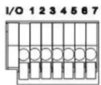
With RS-485 support, the IS-IP200-IRB/IS-IP220-IRB-30 is capable of working with a Pan Tilt Head for pan and tilt control. Before implementing pan/tilt control, please ensure the Pan & Tilt Head is correctly connected to the IS-IP200-IRB/IS-IP220-IRB-30's RS-485 port.
Pin Definition for IS-IP200-IRB/IS-IP220-IRB-30'sRS-485 Port
- D—
- D+
2.5.1 Preset
The Preset Setting can be found under this path: Pan Tilt> Preset.

NOTE: Before setting this function, users must enable the Pan/ Tilt Control first. Please refer to Pan/TiltControl for more details.
There are up to 127 preset points that can be set in the Preset setup page. Please follow the steps below to set and run preset points.
PresetPointsSetup
Step 1. Move the camera to the desired position by moving the mouse cursor onto the screen, one left click on mouse, and then dragging the red arrow to pan/tilt. Users may adjust the zoom position as well.
Step 2. Once a Preset Point is defined, please assign a number (between 1 and 127) and enter it into the input field.
Step 3. Click on the <√> button to save the defined preset point.
PresetRun
Type the Preset Point number into the Preset field, click on the and the camera will turn to the appointed point.

button,
2.5.2 Sequence
The Sequence Setting can be found under this path: Pan Tilt> Sequence.
The Sequence function supports totally eight Sequence Lines; each Sequence Line consists of up to 64 Preset Points. Please refer to the instructions below to program a Sequence Line.

NOTE: Before setting this function, users must pre-define at least two Preset Points.
SequenceSetting
- Sequence Line
Please select the number of Sequence Line to be set from the drop-down list.
• Sequential Preset Points Setting
Please setup each Preset Point of the programmed Sequence Line in order, assigning a Preset Point from the "NO" list for the specified number of Preset Point and entering Dwell Time (0\~255 sec.) into the corresponding fields.
- Sequence Reset
To reset the sequence setting of each line, please click on the
When finishing the sequential Preset Points setting, please click on the button
Sequence Run
Select the specified Sequence Line from the drop-down list, click on the button, and then the camera will start moving forward each scene sequentially as programmed.
To view the camera executing a Sequence Line in full screen mode, please move the cursor onto the live view pane, right-click and left-click to select "fullscreen". Then users can view the camera navigation in full screen.
To stop running the Sequence Line, simply move the cursor to the live view pane and move the camera in any direction.
2.5.3 Pan/Tilt Control
The Pan/Tilt Control Setting can be found under this path: Pan Tilt> Pan/Tilt Control.
Users can activate the pan/ tilt function and select the RS-485 protocol which the Pan Tilt Head uses in the Pan/ Tilt Control page.
Pan/TiltControl
Users can enable or disable the Pan/ Tilt Control.
Click on
RS-485ProtocolType
Protocol and Baud rate type options include:
•DSCP (9600)
•PelcoD (2400)
•PelcoD (4800)
•PelcoD (9600)
•PelcoP (2400)
•PelcoP (4800)
•PelcoP (9600)
Click on
Move the camera to the desired position by moving the mouse cursor onto the screen, one left click on mouse, and then dragging the red arrow to pan/tilt.
2.6 Logout
Click on the tab
Appendix A: Install UPnP Components
Please follow the instructions below to install UPnP components on Windows Vista/Windows XP/Windows 7.
Step1: In the Windows, go to
Step 2: Click on
Step 3: Select
Step 4: Select
Step 5: Click on
Step 6: Click on