MegaBall AV1145 - Security Camera Arecont Vision - Free user manual and instructions
Find the device manual for free MegaBall AV1145 Arecont Vision in PDF.


| Product Type | Security Camera |
| Brand | Arecont Vision |
| Model | MegaBall AV1145 |
| Series | MegaBall |
| Mounting Type | Wall Mount (AV1145-W) or In-Ceiling Dome (AV1145-D) |
| Indoor/Outdoor | Indoor Use Only |
| Image Sensor | Megapixel CMOS (exact resolution not specified; likely 1.3MP or higher) |
| Lens Type | Fixed focal or vari-focal depending on configuration |
| Pan Range | 360° |
| Tilt Range | 90° |
| Yaw (Z-axis) Range | 360° |
| Power Supply | Power over Ethernet (PoE) 802.3af compliant or external AC/DC via pigtail |
| Connector | RJ45 for PoE and data; pigtail for auxiliary power, digital I/O |
| Digital I/O | Opto-isolated; Digital IN and Digital OUT (with debounce) |
| Security Feature | Security L-Key to deter tampering |
| Included Accessories | CD with AV100 software, mounting template, screws, hex key (fixed lens), security L-key |
| Required Tools (not included) | #1 Phillips head screwdriver |
| Software | AV100 Application Manager for camera discovery and setup |
| License Key | Required for recording functionality |
| Focus Adjustment | Manual via lens adapter (fixed focal) or using L-key for focus/zoom/iris (vari-focal) |
| Dome Cover (Dome version) | Vandal-resistant, removable with three screws, optional O-ring and bubble |
| Warranty | Does not cover incorrect installation practices (per manual caution) |
Frequently Asked Questions - MegaBall AV1145 Arecont Vision
User questions about MegaBall AV1145 Arecont Vision
0 question about this device. Answer the ones you know or ask your own.
Ask a new question about this device
Download the instructions for your Security Camera in PDF format for free! Find your manual MegaBall AV1145 - Arecont Vision and take your electronic device back in hand. On this page are published all the documents necessary for the use of your device. MegaBall AV1145 by Arecont Vision.
USER MANUAL MegaBall AV1145 Arecont Vision
natural_image
Close-up of three black surveillance cameras mounted on a curved surface, no visible text or symbolsMegaBall™
Installation Manual

Arecont Vision
megapixel technology...
beyond imagination
MegaBall™ Wall Mount Version (-W) Installation Manual
Inside the box:
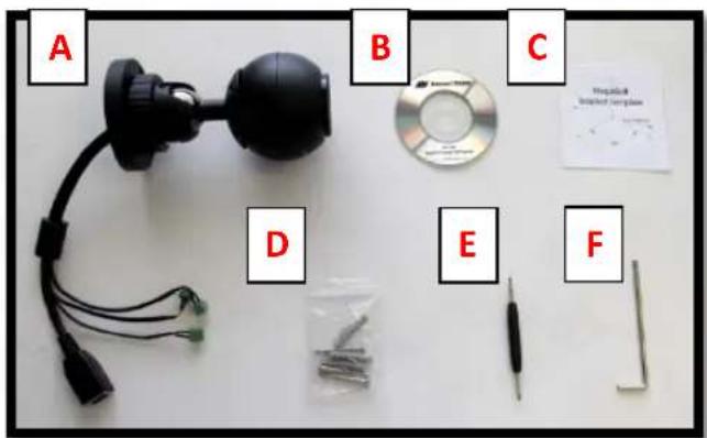
A. Arecont Vision MegaBall™ camera with wall mount (indoor use only)
B. CD with AV100 software and user manuals (license key required for recording)
C. Mounting template
D. Pack of three (3) wood screws and three (3) dry wall anchors
E. One double-sided hex key (fixed focal lens version only)
F. Security L-Key
Not included but needed:
• #1 Phillips head screwdriver
text_image
A B C D E FImage 1
Mounting the Camera:
- Remove the camera and hardware from the box.
-
Using the mounting template, prepare the mounting surface for camera installation.
-
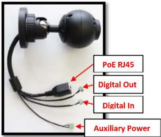
Plug the Ethernet cable into the MegaBall™ PoE female RJ45 connector. (Image 2) NOTE: If the camera will be powered via PoE, please skip to step 5.
text_image
PoE RJ45 Digital Out Digital In Auxiliary PowerImage 2
- If the camera will be powered by an AC or DC power supply, connect external power with pigtail cable connector.
NOTE 1: Ensure that the polarity of the DC input on the camera matches the way that the wires are installed in the connector shown in Image 2.
NOTE 2: AC power does not have polarity.
- Align the holes on the camera wall mount with the prepared holes on the mounting surface. Attach the camera to the mounting surface with the wood screws or any other hardware suitable for the mounting surface.
Adjusting the Tilt, Pan, Z-Axis (yaw):
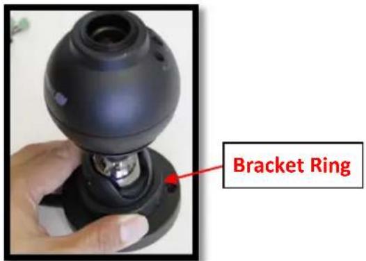
- To adjust the camera tilt, pan or z-axis (yaw), loosen the ring on the wall mount bracket as shown in Image 3 then adjust as necessary and retighten the ring.
text_image
Bracket RingImage 3
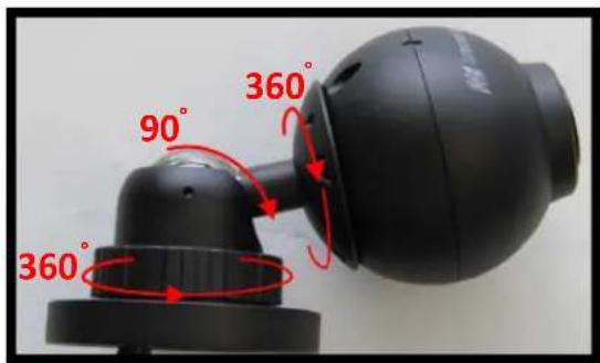
NOTE : The 3-axis bracket allows 360^ camera body rotation, 90^ tilt and 360^ bracket rotation for easy installation in any location. (Image 4)
text_image
360° 90° 360°Image 4
CAUTION: Adjusting the camera without loosening the bracket ring may result in scratches on the bracket joint. Incorrect
installation practices are not covered under warranty!
Adjusting the Focus, Iris and Field of View:
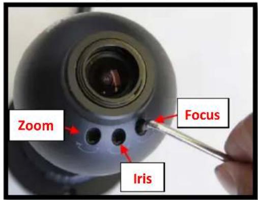
- For the vari-focal model, adjust the focus, iris and field of view using the provided Security L-Key (Image 1F) as shown in Image 5.
text_image
Zoom Focus IrisImage 5
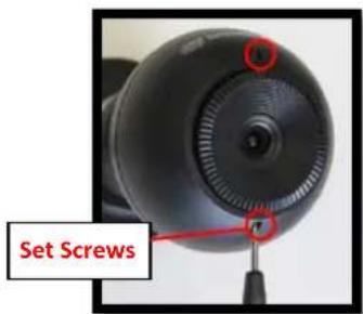
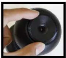
- For the fixed-focal model, adjust the focus by loosening the two set screws on the front shell as shown in Image 6 using supplied double sided hex key (Image 1E). Adjust the lens adapter to focus the camera as shown in Image 7. Retighten the set screws once focusing is complete.
text_image
Set ScrewsImage 6
natural_image
Close-up of a hand holding a black circular object with a central dot, no visible text or symbolsImage 7
MegaBall™ Dome Version (-D) Installation Manual
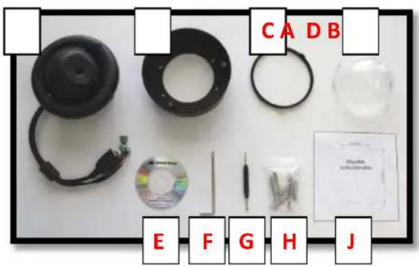
Inside the box:
A. Arecont Vision MegaBall™ camera with in-ceiling mount (indoor use only)
B. Surface mount (preassembled on dome)
C. O-ring (preassembled on bezel)
D. Dome cover (Bubble)
E. CD with AV100 software and user manuals (license key required for recording)
F. Security L-Key
G. One double-sided hex key (fixed focal lens version only)
H. Pack of three (3) wood screws and three (3) dry wall anchors
J. Mounting template
Not included but needed:
• #1 Phillips head screwdriver
text_image
CA DB E F G H JImage 1
Mounting the Camera:
-
Remove the camera and hardware from the box.
-
Using the mounting template, prepare the mounting surface for camera installation
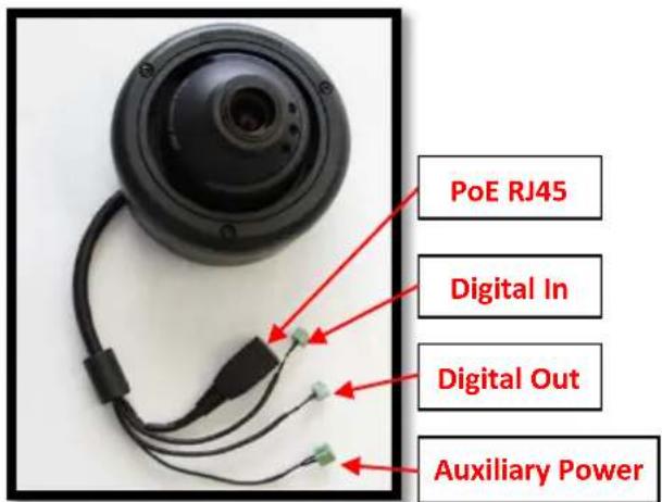
- Plug Ethernet cable into the MegaBall™ PoE female RJ45 connector. (Image 2) NOTE: If the camera will be powered via PoE, please skip to step 5.
text_image
PoE RJ45 Digital In Digital Out Auxiliary PowerImage 2
- If the camera will be powered by an AC or DC power supply, connect external power with pigtail cable connector.
NOTE 1: Ensure that the polarity of the DC input on the camera matches the way that the wires are installed in the connector shown in Image 2.
NOTE 2: AC power does not have polarity.
Arecont Vision MegaBall™ Installation Manual
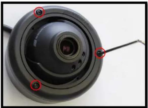
- Using the provided Security L-key (Image 1F), loosen the three (3) screws securing the dome cover (Image 3). Remove the vandal resistant dome cover. NOTE: Do not remove the screws from the dome cover.
natural_image
Close-up of a black circular mechanical component with red annotations pointing to features, no visible text or symbols.Image 3
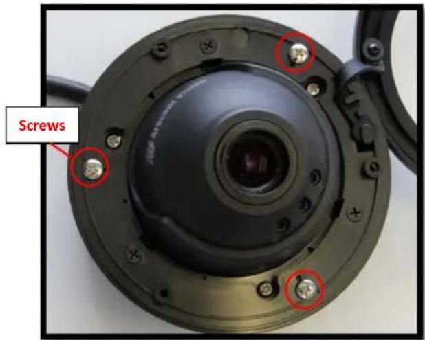
- Loosen the three (3) machine screws (Image 4) and remove the in-ceiling mount camera from the surface mount housing. (Image 4)
text_image
ScrewsImage 4
In-ceiling Mount Installation (Optional)
- Using the mounting template, cut a hole in the surface for mounting.
- Insert the in-ceiling mount camera into the hole.
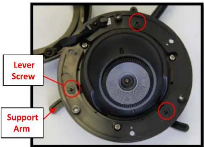
- Tighten the "lever screws" until the flush mount is snug, as shown in Image 5. The "Support Arm" will ride down the screw to compress the mounting surface. NOTE: Do not over-torque the lever screws.
text_image
Lever Screw Support ArmImage 5
Surface mount installation
- Align the holes in the surface mount with the prepared holes on the mounting surface with the wood screws or any optional hardware suitable for the mounting surface.
- Attach the in-ceiling camera to the surface mount.
Adjusting the Tilt, Pan, Z-Axis (Yaw):
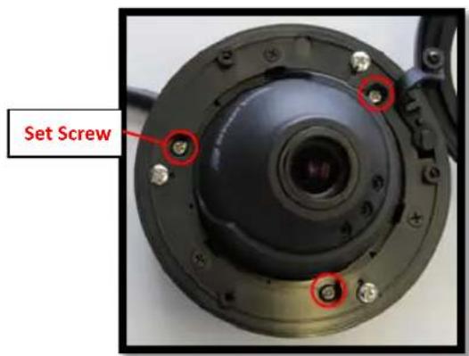
- To adjust the camera tilt, pan or z-axis (yaw), loosen the 3 set screws on the in-ceiling mount as shown in Image 6. Then adjust as necessary and retighten the 3 set screws.
text_image
Set ScrewImage 6
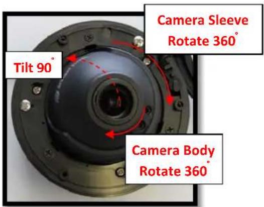
NOTE : The 3 axis in-ceiling camera allows 360^ camera body rotation, 90^ tilt, and 360^ camera sleeve rotation for easy installation in any location as shown in Image 7.
text_image
Camera Sleeve Rotate 360° Tilt 90° Camera Body Rotate 360°Image 7
Adjusting the Focus, Iris and Field of View:
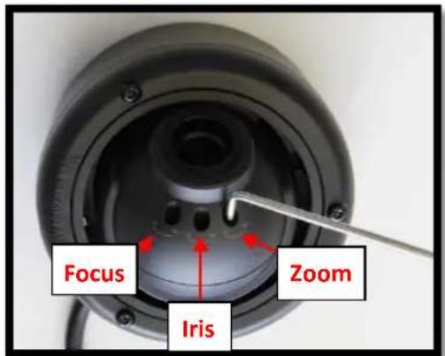
- For the vari-focal model, adjust focus, iris and field of view using the provided Security L-Key (Image 1F) as shown in Image 8.
text_image
Focus Zoom IrisImage 8
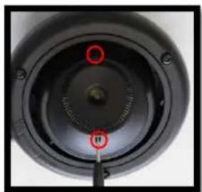
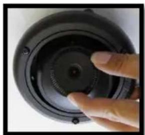
- For the fixed-focal model, adjust the focus by loosening the two set screws on the front shell as shown in Image 9 using the supplied double sided hex key (Image 1G).
natural_image
Close-up of a black circular mechanical component with red circular highlights and a central knob (no text or symbols visible)Image 9
natural_image
Close-up of a hand adjusting a black circular mechanical component with a central knob (no text or symbols visible)Image 10
- Adjust the lens adapter to focus the camera as shown in Image 10. Retighten the set screws once focusing is complete.
Arecont Vision MegaBall™ Installation Manual
Dome Cover (Bubble) Installation (Optional):
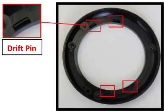
- Remove the O-ring (Image 1C) from the bezel by pushing on the 4 drift pins on the back of bezel shown in Image 11.
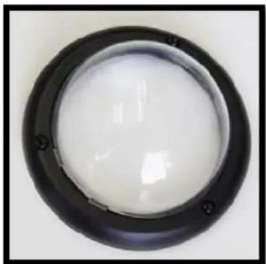
- Attach the provided dome cover (Image 1D) to the bezel as shown in Image 12.
text_image
Drift PinImage 11
natural_image
Circular black ring with white interior, no text or symbols visibleImage 12
- Remove the protective film from the bubble. NOTE: Take precaution not to scratch the bubble.
- Secure the dome cover to the camera using the provided Security L-Key (Image 1F.)
Optional: Connecting Digital I/O:
- To use the digital I/O, connect the digital I/O to the pigtail cable connector as shown in Image 2.
NOTE: Table 1 shows the electrical characteristics and Table 2 shows cable color for digital I/O.
| Electrical Characteristics: | Min | Max Camera | |
| Input voltage (V) (measured between + and - terminals) | ON 2.9 6.3 | IR & DN Versions | |
| OFF 0 1.3 | |||
| Output current (mA) (measured between + and - terminals) Applied Voltage Rage: 0 - 80V | ON - 50 | DN version Only | |
| OFF - 0.1 | |||
Table 1
NOTE: Both the input and the output are electrically isolated from the rest of the camera's electrical circuitry via general-purpose photo couplers. The input is additionally protected with a serial 250 Ohm resistor and a debouncing circuit. Duration of any input signal should be at least 5ms to comply with the requirements of the debouncing circuit.
| Yellow | Digital OUT + |
| Red | Digital OUT - |
| Green | Digital IN + |
| Black | Digital IN - |
Table 2
Arecont Vision MegaBall™ Installation Manual
Camera Installation:
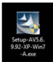
- Install the AV100 application manager Software. (Image 13, found on the CD).
- Run the AV100 application manager by double clicking on the icon shown below. (Image 14, found on your desktop).
text_image
Setup-AV5.6. 9.92-XP-Win7 -A.exeImage 13
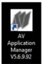
Image 14
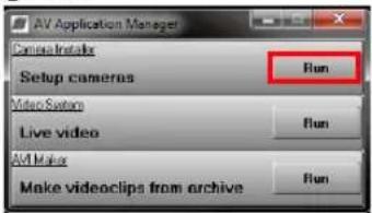
- Select "Run" next to "Setup Cameras" from the AV100 application manager as shown in Image 15 and wait for "Arecont Vision Camera Installer" window to appear as shown in Image 16.
text_image
AV Application Manager Cinema Installs Setup cameras Run Video Sets Live video Run AV Make Make videoclips from archive RunImage 15
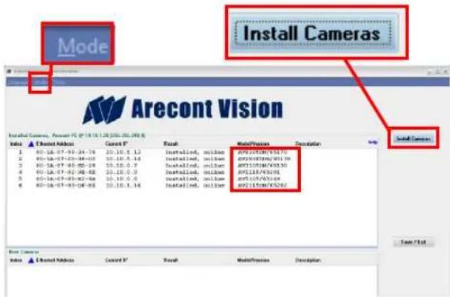
- Click "Mode" tab to select desired install mode on the Arecont Vision Camera Installer as shown in Image 16.
NOTE 1: Basic Mode (default setting): software will automatically discover and change / assign IP address to match PC subnet.
NOTE 2: Advanced Mode: software will automatically discover but allow manual update of
the IP address. See "AV100 Installation Manual" (found on the CD) for details on Advanced Mode.
NOTE3: User can verify camera model number and FW version of all cameras as shown in Image 16.
text_image
Mode Arecont Vision Install Cameras, Camera PC @ 19.10.1.28 (2006.05.2013) Model/Preview Description Install Cameras 1 80-18-07-90-24-78 20.10.5.13 Installied, allian: 897105186/74370 2 80-18-07-22-38-02 20.10.5.18 Installied, allian: 897105186/74370 3 80-18-07-90-28-28 15.10.5.7 Installied, allian: 897105186/74370 4 80-18-07-92-38-82 20.10.5.9 Installied, allian: 897123/74361 5 80-18-07-93-38-86 20.10.5.6 Installied, allian: 897105/63524 6 80-18-07-93-04-95 20.10.5.16 Installied, allian: 897215/635292 Note / List Model / Extended Address Current N° Refresh Model/Preview DescriptionImage 16
- For basic mode, select "Install Cameras" on the Arecont Vision Camera Installer as shown in Image 16.
- Confirm that all the cameras connected to the network switch appear in the upper window.
- Repeat Step 25 if all of the cameras do not appear in the upper window.
CAUTION: If the software does not find a camera, the software utility may be blocked by the anti-virus or Windows® firewall. Before turning them off, please consult your IT manager.
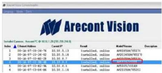
NOTE : Double click the camera model on the Camera Installer as shown in Image 17 to access the camera web interface. See "AV Camera Web Page User Manual" (found on the CD) for details on the web interface.
Arecont Vision MegaBall™ Installation Manual
text_image
Aurecont Vision Installed Version: Arecont/PC @ 10.18.1.28 [55.259.24.0] Index ▲ Ethernet Address Cancel P° Basic Model Version Description 1 00-16-07-18-34-76 10.10.5.13 Installed, online AWS18518/65170 2 00-16-07-18-34-92 10.10.5.14 Installed, online AWS24509/65170 3 00-16-07-18-34-28 10.10.5.7 Installed, online AWS36566/65336 4 00-16-07-18-34-48 10.10.6.9 Installed, online AWS31724/65388 5 00-16-07-18-34-94 10.10.6.9 Installed, online AWS165/65149 6 00-16-07-18-34-26 10.10.1.14 Installed, online AWS21518/65202Image 17
- When all cameras are discovered and installed and display "Installed, online", select "Save/Exit." The AV100 application main menu will appear.
- From the "AV100 Application Manager" menu, select "Run" next to "Live video" to view live images.
NOTE: See the "AV100 Installation Manual" (found on CD) for details on camera configurations.
Leading
the way in
Megapixel
video
Arecont Vision
425 E. Colorado Street, 7th Floor
Glendale, CA 91205
support@arecontvision.com
www.arecontvision.com
+1.818.937.0700
877.CAMERA.8

Arecont Vision
megapixel technology...
beyond imagination