
FC-348 - Security Camera FLIR - Free user manual and instructions
Find the device manual for free FC-348 FLIR in PDF.


User questions about FC-348 FLIR
0 question about this device. Answer the ones you know or ask your own.
Ask a new question about this device
Download the instructions for your Security Camera in PDF format for free! Find your manual FC-348 - FLIR and take your electronic device back in hand. On this page are published all the documents necessary for the use of your device. FC-348 by FLIR.
USER MANUAL FC-348 FLIR
natural_image
Line drawing of a FLIR air conditioner unit (no text or symbols on the device itself)F—Series S
F—Series R
© 2015 FLIR >systems, In_. All rights reserved worldwide.
<'mes 'nd m'rks 'ppe'ring on the produ_ts herein 're either registered tr'dem'rks or tr'dem'rks of FLIR>ystems, In_. 'nd/or its subsidiaries. All other tr'dem'rks, tr'de n'mes, or _omp'ny n'mes referen_ed herein 're used for identifi_'tion only 'nd 're the property of their respe_tive owners.
his produ_t is prote_ted by p'tents, design p'tents, p'tents pending, or design p'tents pending.
μhe _contents of this do_ument 're subje_t to _h'nge.
FLIR Systems, Inc.
70 C'stili'n Drive
Golet', CA 93117
Phone: 888.747.FLIR (888.747.3547)
Intern'tion'l: +1.805.964.9797
http://www.flir._om
Important Instructions and Notices to the User:
Modifi'_tion of this devi_e without the express 'uthoriz'tion of FLIR Commer_i'l >systems, In_. m'y void the user's 'authority under FCC rules to oper'te this devi_e.
Note 1: μhis equipment h's been tested 'nd found to _omply with the limits for 'Cl'ss B digit'l devi_e, pursu'nt to P'rt 15 of the FCC rules. μhese limits 're designed to provide re'son'ble prote_tion 'g'inst h'rmful interferen_e in 'residenti'l inst'll'tion. μhis equipment gener'tes, uses, 'nd_'n r'di'te r'dio frequen_y energy 'nd, if not inst'llled 'nd used in '__ord'n_e with the instru_tions, m'y _'use h'rmful interferen_e to r'dio _ommuni_tions. However, there is no gu'r'ntee th't the interferen_e will not o_ur in 'p'rti_ul'r inst'lltion. If this equipment does _'use h'rmful interferen_e to r'dio or television re_option, whi_h_'n be determined by turning the equipment off 'nd on, the user is en_our'ged to try to _orre_t the interferen_e by one or more of the following me'sures:
- Reorient or relo'te the re_eiving 'ntenn';
- In_re'se the sep'r'tion between the equipment 'nd re_eiver;
- Conne_t the equipment into 'n outlet on ' _ir_uit different from th't of the re_eiver; 'nd/or
- Consult the de'ler or 'n experien_ed r'dio/television te_hni_i'n for help.
Note 2: μhis equipment w's tested for _ompli'n_e with the FCC limits for 'Cl'ss B digit'l devi_e using 'shielded_'ble for _onne_ting the equipment to 'n 'n'log video output to 'monitor 'nd using 'shielded =>B_'ble for _onne_ting the equipment to 'person'l _omputer. When m'king su_h _onne_tions, shielded_'bles must be used with this equipment.
Industry Canada Notice:
μhis Cl'ss B digit'l 'pp'r'tus _omplies with C'n'di'n ICE>-003.
Proper Disposal of >lectrical and >electronic >quipment (>>>

μhe Europe'n =nion (E=) h's en' ted W'ste Ele_tri_1 'nd Ele_troni_ Equipment Dire_tive 2002/96/EC (WEEE), whi_h 'ims to prevent EEE w'ste from 'rising; to en_our'ge reuse, re_y_ling, 'nd re_overy of EEE w'ste; 'nd to promote environment'l responsibility.
In '__ord'n_e with these regul'tions, 'll EEE produ_ts I'beled with the "rossed out wheeled bin" either on the produ_t itself or in the produ_t lit'er ture must not be disposed of in regul'r rubbish bins, mixed with regul'r household or other ommer_i'l w'ste, or by other regul'r muni_ip'l w'ste_olle_tion me'ns. Inste'd, 'nd in order to prevent possible h'rm to the environment or hum'n he'tlh, 'll EEE produ_ts (in_luding 'ny_bles th't
_'me with the produ_t) should be responsibly dis_'rded or re_y_led.
μo identify ' responsible dispos'l method ne'rby, ple'se _ont'_t the lo_'l w'ste _olle_tion or re_y_ling servi_e, the origin'l pl'_e of pur_h'se or produ_t supplier, or the responsible government 'authority in the 're'. Business users should _ont'_t their supplier or refer to their pur_h'se _ontr'_t.
Document History
xersion D'te Comment
100 April 2014 Initi'l Rele'se
110 June 2014 Minor_orre_tions
120 M'y 2015 Added des_ription of An'lyti_s setup, des_ription of IDR, other minor_orre_tions
Table of Contents
Camera Installation
1.1 W'rnings 'nd C'utions 1-1
1.2 Referen_es 1-1
1.3 Inst'll'tion °verview 1-2
1.3.1 C'mer' Conne_tion °ptions .... 1-2 Gener'l Purpose Input/°utput (GPI°) .... 1-2 PoE+ Power >upplies .... 1-2
1.3.2 C'mer' A essories 1-3
1.3.3 >upplied Components 1-3
1.3.4 Required >upplies 1-3
1.4 Lo_tion Consider'tions 1-3
1.4.1 C'mer' Mounting for Re'r C'ble A__ess 1-4
1.4.2 C'mer' Mounting with Con_e'led C'ble W'll Mount ....1-5
1.4.3 >unshield 1-6
1.5 Removing the Cover 1-6
1.6 C'mer' Conne_tions 1-7
1.6.1 Prior to Cutting/Drilling Holes 1-7
1.6.2 Configuring the Lens He'ter Jumper 1-8
1.6.3 Ben_h μesting 1-8
1.6.4 An'log xideo Conne_tions 1-8
1.6.5 Conne_ting Power 1-9
1.6.6 Ethernet 1-9
1.6.7 GPI° Conne_tions 1-10
1.6.8 C'mer' Grounding 1-11
1.7 Re'r A__ess C'ble Gl'nd >e'ling 1-11
1.8 Con_e'led C'ble Mount A_essory 1-12
1.9 C'mer' spe_ifi'tions 1-15
9asic Operation and Configuration
2.1 IP C'mer', °
2.1.1 >erver Configuration .....2-1
2.2 B'si_ μest 'nd Configur'tion >teps 2-2
2.3 C'mer' Ben_h μest 2-2
2.3.1 μesting IP Communi_tions 2-2
2.3.2 Log in to the C'mer' Web P'ge 2-3
2.3.3 Live xideo P'ge ....2-4
μemper'ture—FC->eries R _'mer' only ....2-5
C'mer' Control 'nd >t'tus ....2-5
Web Control P'nel ....2-5
2.3.4=sing F>M 2-7
2.3.5 Running F>M 2-8
2.4 B'si_C'mer' Configur'tion 2-10
Table of Contents
2.4.1 >etup Menu 2-10
2.4.2 >erver Menu .... 2-10
3.3 Restoring the F'_tory >ettings ....3-29
natural_image
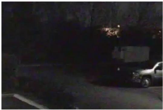
Night street scene with a parked car and cargo box, no visible text or symbolsImage from a standard camera in low light
natural_image
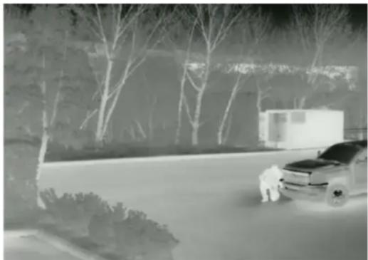
Black-and-white photo of a car parked on a roadside with trees and a distant building (no visible text or symbols)Image from a thermal camera in the same conditions
1 Camera Installation
μhis m'nu'l des_ribes the inst'll'tion 'nd initi'l _onfigur'tion of the FC->eries IP therm'l_'mer's, whi_h in_ludes the FC->eries > 'nd FC->eries R_'mer' models. μhese_'mer' models 're simil'r in design 'nd the physi_'l mounting 'nd inst'll'tion of both models is the s'me. μhe FC->eries R_'mer's h've 'll the fe'tures of the FC->eries > plus 'n 'ddition'l R'diometry fe'ture th't provides the 'bility to issue 'l'rms b'sed on temper'ture. If help is needed during the inst'll'tion pro_ess, _ont'_t the lo_'I FLIR servi_e represent'tive or,_'ll 888-747-3+47 inside the =>.
All inst'llers 'nd integr'tors 're en_our'ged to t'ke 'dv'nt'ge of the tr'ining offered by FLIR; visit http://www.flir. om/tr'ining for more information.
μhis m'nu'l in_ludes the following topi_s:
- Inst'll'tion overview
- Mounting the _mer' 'nd its _components
- Conne_ting the ele_troni_s
- Ben_h testing the _'mer'
- B'si__onfigur'tion 'nd oper'tion of the _mer'
- C'mer' >pe_ifi_'tions
For s'fety, 'nd to '_hieve the highest levels of perform'n_e from the FC->eries_'mer' system, 'lw'ys follow the w'rnings 'nd_'utions in this m'nu'l when h'ndling 'nd oper'ting the_'mer'.
1.1 Warnings and Cautions
Warning!

If mounting the FC->eries _'mer' on 'pole, tower or 'ny elev'ted lo_tion, use industry st'nd'rd s'fe pr'_ti_es to 'void injuries.
Caution!
Ex_ept 's des_ribed in this m'nu'l, do not open the FC->eries _mer' for 'ny re'son. D'm'ge to the _mer' _n o__ur 's the result of _reless h'ndling or ele_trost'ti_dis_h'rge (E>D). Alw'ys h'ndle the _mer' with _re to 'void d'm'ge to ele_trost'ti_-sensitive _components.
Prior to m'king 'ny _onne_tions, ensure the power supply or _ir_uit bre'ker is swit_hed off.
Be _'reful not to le've fingerprints on the FC->eries _'mer"s infr'red opti_s.
°per'ting the _mer' outside of the spe_ified input volt'ge r'nge or the spe_ified oper'ting temper'ture r'nge _n _use perm'nent d'm'ge.
1.2 References
FLIR Do_ # 427-00"-"-19> FC->eries > Interf'_e Control Do_ument (ICD), 'v'il'ble on the do_umenttion CD or from the FLIR website, provides further det'ils reg'rding me_h'ni_'l dimensions 'nd mounting for the FC->eries _'mer'.
FLIR Do_ # 427-0030-00-28 Nexus IP Camera Configuration Guide, provides more information on setting or _h'nging _mer' p'r'meters.
μthese do_uments 're provided for referen_e only.
1.3 Installation Overview
μhe FC-Series c'mer' is 'n infr'red therm'l im'ging c'mer' intended for outdoor security 'ppllc'tions, 'nd c'n be inst'lled in 'fixed loc'tion or on ' p'n/tilt mech'nism. μhe FC-Series c'mer' is intended to be mounted on ' medium-duty fixed pedest'l mount or w'll mount commonly used in the security industry. μhe c'mer' mount must support up to 5 lbs (2.3 kg).
C'bles m'y exit from the b'ck of the c'mer' housing through the supplied c'ble gl'nd or from the bottom of the c'mer' housing when using the conce'led c'ble w'll mount (sold sep'r'tely). A c'ble gl'nd plug is supplied for the re'r of the c'mer' housing when c'bles 're routed using the conce'led c'ble w'll mount.
natural_image
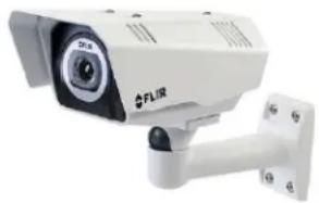
Front view of a white FLIR security camera with mounted sensor array (no visible text or symbols)1.3.1 Camera Connection Options
μhe FC-Series c'mer' c'n be inst'llled with 'n 'n'log or digit'l (IP) video output (or both). An'log video will require ' connection to ' video monitor or 'n 'n'log video m'trix switch. μhe c'mer' c'n be powered using Power over Ethernet Plus (PoE+) or with ' convention'l 24 V ('c or dc) power supply. For ' PoE+ connection, 'n 'ccessory PoE+ power supply (PN 4132391, 'Iso c'lled ' PoE+ injector) is 'v'il'ble if the c'mer' is not connected to ' PoE+ switch. μhe m'ximum Ethernet c'ble run is 100 meters including the PoE+ power supply. In inst'll'tions using PoE+ power 'nd IP video, only ' single Ethernet c'ble from the c'mer' is required.
In inst'll'tions using 'n'log video 'nd convention'l power (24 V'c is commonly used in m'ny inst'll'tions), 'n RG59U co'xi'l c'ble 'nd ' three-conductor power c'ble 're inst'lled. It is recommended 'n Ethernet c'ble should 'Iso be inst'lled for c'mer' configur'tion, oper'tion 'nd troubleshooting. μhe FC-Series c'mer' does not support seri'l communications.
General Purpose Input/Output (GPIO)
μhe c'mer' c'n receive ' single "cont'ct closure" input sign'l 'nd c'n provide ' single "cont'ct closure" output sign'l. Refer to GPIO Connections, pg. 1-10.
Po>+ Power Supplies
With PoE+, c'mer' power is delivered to the c'mer' vi' the norm'l Ethernet c'ble vi' the c'mer's st'nd'rd RJ-45 Ethernet connector. μhe FC-Series c'mer' is 'Powered Device compli'nt with the IEEE 802.3't-2009 st'nd'rd, known 's PoE+ or PoE Plus. μhe FC-Series c'mer' is 'Iso b'ckw'rd comp'tible with the older IEEE 802.3'f-2003 st'nd'rd.
When connected to Power Sourcing Equipment compli'nt with the e'rlier, lower power IEEE 802.3'f-2003 st'nd'rd, the limited power 'v'il'ble to the FC-Series c'mer' will prevent the form'tion of frost 'nd ice. However, the limited power 'v'il'ble from 802.3'f-2003 will not fully 'chieve the c'mer"s st'ted specific'tion for de-icing from cold st'rt when the extern'l environment temper'ture is < 0 °C. In 'll other w'ys the c'mer' will oper'te norm'lly with Ethernet Powered Sourcing Equipment compli'nt to either IEEE PoE st'nd'rd.
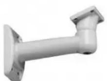
Concealed Cable
Wall Mount
1.3.2 Camera Accessories
μhe following '__essories 're 'v'il'ble for pur_h'se from FLIR >systems, In_.
- PoE+ power supply (P<4132391) - For powering 'single FC->eries_'mer' using PoE+. In 'ddition to PoE+ power 'nd _ommuni_'tions, the power supply provides surge prote_tion. It _omplies with IEEE 802.3't 'nd is b'_kw'rd _omp'tible with the IEEE802.3'f st'nd'rd.
- Con_e'led C'ble W'll Mount (P<4129742) - In_ludes_'mer' mount g'sket 'nd hex wren_h for 'djusting the b'll joint _ontrolling the_'mer"s view 'ngle. μhe FC->eries_'mer' is 'tt'_hed to the mounting 'rm using the four M5 thre'ded bottom mounting holes. A_'ble gl'nd plug is supplied with the_'mer' for the re'r of the_'mer' housing when_'bles're routed using the _on_e'led_'ble_' essory. Refer to C'mer' Mounting with Con_e'led C'ble W'll Mount, pg_1-5 for inst'll'tion instru_tions.
- Pole Mount Ad'pter Kit - (P< 4132982) - Ad'pter kit th't 'llows the Con_e'led C'ble W'll Mount to be mounted to ' pole (75 mm [3 in] min to 180 mm [7 in]; l'rger pole di'meter requires use of _ustomer supplied b'nd _l'mps)
1.3.3 Supplied Components
μhe FC->eries _'mer' p'_k'ge in_ludes these st'nd'rd _omponents:
- Fixed C'mer' =nit with sunshield 'nd inst'lled _'ble gl'nd
- C'ble gl'nd plug 'nd gl'nd inserts for se'ling _ 'mer' housing
- Power termin'l blo_k plug
- A__essory termin'l blo_k plug
- μools: 3 mm hex wren_h (μ-H'ndle), sm'll bl'de s_rewdriver
- FC->eries C'mer' Do_ument'tion P'_k'ge
1.3.4 Required Supplies
μhe inst'ller will need to supply the following items 's required (spe_ifi_ to the inst'll'tion).
- Power _'ble if used for system power, 3-_ondu_tor, shielded, g'uge determined by _'ble length 'nd supply volt'ge
- PoE+ power supply or PoE+ swit_h if used for system power
- C't5e Ethernet _'ble for digit'l video 'nd/or PoE+ for system power
- Co'xi'l RG59=_'bles (B<C _onne_tor 't the _mer' end) for 'n'log video
- C'mer' grounding str'p, _ 'mer' mount, mis_ell'neous ele_tri_'I h'rdw're, _onne_tors, 'nd tools
Be sure to use _'bles th't fit in the _'ble gl'nd holes, 's des_ribed below. Refer to Re'r A__ess____C'ble Gl'nd >e'ling, pg. 1-11 for more inform'tion.
1.4 Location Considerations
μhe 'mer' will require _onne_tions for power 'nd video. Ensure th't _'ble dist'n_es do not ex_eed the spe_ifi_tions 'nd th't _'bles 'dhere to 'll lo_'l 'nd industry st'nd'rds, _odes, 'nd best pr'_ti_es. μhe FC->eries _'mer' must be mounted upright, either on top of the mounting surf'_e. or underne'th 'n overh'nging mounting surf'_e su_h 's e'ves or 'n 'wning. μhe unit should not be mounted upside down.
1.4.1 Camera Mounting for Rear Cable Access
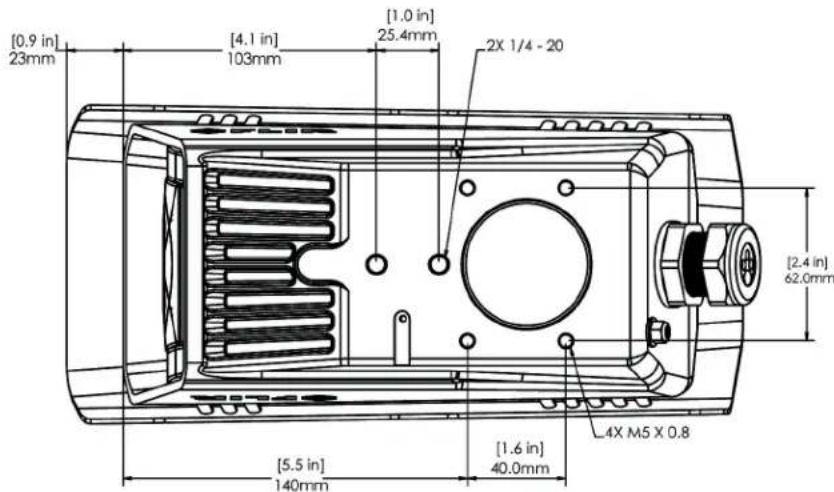
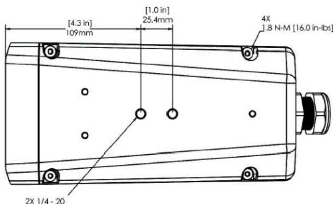
μhe FC9>eries _'mer' _'n be se_ured to the mount with two in9line 1/4920 thre'ded f'steners on the top or bottom of the _'mer'. Altern'tively the _'mer' _'n be mounted with four M+ x 0.8 thre'ded f'steners to the bottom of the _'mer'. =se Lo_tite 222 low strength thre'dlo_ker for the top mount f'steners (_'n be used with the bottom mount f'steners 'Iso). Refer to the FC9>eries ICD for 'ddition'l inform'tion.
If using two 1/4920 f'steners in the _enter of b'se, the m'ximum depth of the f'stener should not ex_eed 12.+ mm (0.+ in). If using four M+ x 0.8 f'steners, the m'ximum depth of the f'stener should not ex_eed 10.0 mm (0.4 in).
text_image
[0.9 in] 23mm [4.1 in] 103mm [1.0 in] 25.4mm 2X 1/4 - 20 [2.4 in] 62.0mm [5.5 in] 140mm [1.6 in] 40.0mm 4X M5 X 0.8Figure 1-1: FC-Series Camera 9ottom Mounting Holes
text_image
[4.3 in] 109mm [1.0 in] 25.4mm 4X 1.8 N-M [16.0 in-lbs] 2X 1/4 - 20Figure 1-2: Top Side Mounting Holes
If using two 1/4920 f'steners in the _enter of top, the m'ximum depth of the f'stener should not ex_eed 12.+ mm (0.+ in). If the _mer' is mounted using the top of the _mer', the sunshield must be removed.
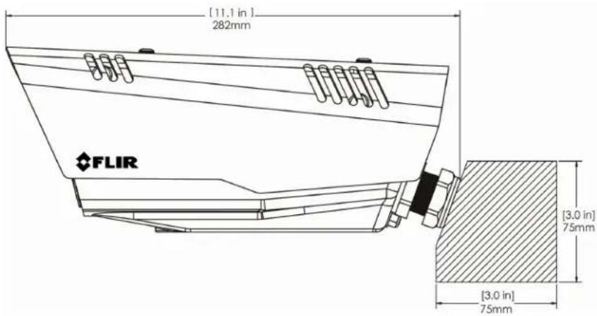
As the di'gr'm below indi_'tes, be sure to 'llow 'dequ'te sp'_e for _'ble egress behind the gl'nd. μhis requirement m'y v'ry, depending on the inst'll'tion. M'int'in the bend r'dius per the re_ommend'tion of the _'ble m'nuf'_turer. μhe typi_l _'ble bend r'dius is +097+mm (293 in).
text_image
[11.1 in] 282mm FLIR [3.0 in] 75mm [3.0 in] 75mmFigure 1-3: Rear Cable 9end Radius
1.4.2 Camera Mounting with Concealed Cable Wall Mount
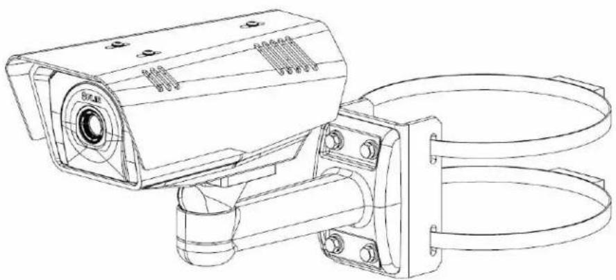
μhe FC9>eries _'mer' _'n be se_ured to the option'l Con_e'led C'ble W'll Mount with four M+ x 0.8 thre'ded f'steners to the bottom of the _'mer'. =se Lo_tite 222 low strength thre'dlo_ker for the mount f'steners. Refer to Con_e'led C'ble Mount A essory, pg. 1912 for 'ddition'l inform'tion.
natural_image
Technical line drawing of a surveillance camera with attached bracket (no text or symbols)Figure 1-4: FC-Series Installed with Concealed Cable Wall Mount and Pole Adapter kit
1.4.3 Sunshield
μhe _mer' in_ludes ' sunshield whi_h should be used for 'ny inst'll'tion where the _mer' is exposed to dire_t sunlight or pre_ipit'tion, If the _mer' is mounted with the top mounting holes, the sunshield is not used. Depending on the needs of the inst'll'tion, the sunshield _n be positioned in the neutr'l (middle) position, or slightly forw'rd or re'rw'rd. μo _h'nge the position of the sunshield, tempor'rily loosen the three 3 mm hex s_rews on top, slide the sunshield forw'rd or b'_kw'rd, 'nd re9tighten the s_rews.
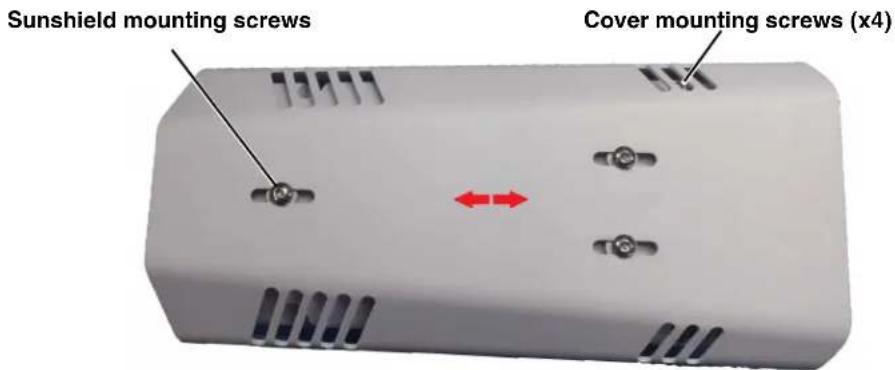
text_image
Sunshield mounting screws Cover mounting screws (x4)Figure 1-5: Sunshield Mounting
1.5 Removing the Cover
In order to 'ess the ele_tri'l_onne_tions 'nd inst'll the _bles, it is ne_ess'ry to tempor'rily remove the top_over of the _mer' housing. μhe top_over of the _mer' is held in pl_e with four 3 mm hex s_rews. μhe s_rews 're 'essible through slots in the sunshield, so the sunshield does not need to be removed from the top_over.
=se ' 3 mm hex key to loosen the four _'ptive s_rews, exposing the _onne_tions inside the _mer' en_losure. μhere is' grounding wire _onne_ted inside the _se to the top _over, 's shown. If it (or 'ny of the grounding wires) is tempor'rily dis_onne_ted during the inst'll'tion, it must be re_onne_ted to ensure proper grounding of the _mer'.
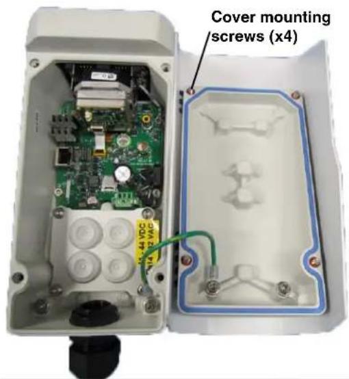
text_image
Cover mounting screws (x4)Figure 1-6: Cover Removed (Sunshield attached)
Caution!
When repl'ing the _over, ensure th't the ground wire between the _over 'nd the 'mer' body is _completely inside the o9ring groove. If the wire is pin_hed between the _over 'nd body the 'mer' is not se'led 'g'inst w'ter ingress 'nd_'n be d'm'ged.
Repl'e the_over 'nd tighten the four 3 mm hex s_rews to 1.8 n9m (16.0 in9lbs).
1.6 Camera Connections
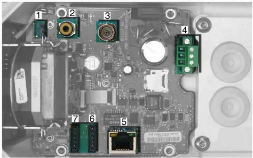
text_image
Labeled diagram of an electronic device showing numbered components including connectors, ports, and a central circuit board.Figure 1-7: Camera Connections
Refer to μ'ble 1-1 for 'des_ription of these _mer' _onne_tions.
Table 1-1: FC-Series Camera Connections
| Connection Purpose | |
| 1 3-pin | Jumper >upplement'l lens he'ter on/off |
| 2 RCA | An'log video test point |
| 3 B< C An'log video | |
| 4 3-pin | μermin'l'_/d_power |
| 5 Ethernet PoE+ power, _ommuni_tions, IP video stre'm | |
| 6 6-pin | termin'l J8 Gener'l purpose I/° |
| 7 A essory inputs Reserved for future use | |
1.6.1 Prior to Cutting/Drilling Holes
When sele_ting ' mounting lo_'tion for the FC->eries_'mer', _onsider_'ble lengths 'nd_'ble routing. Ensure the_'bles 're long enough, given the proposed mounting lo_'tions 'nd_'ble routing requirements, 'nd route the_'bles before inst'lling the _omponents.
=se_'bles th't h've suffi_ient dimensions to ensure s'fety (for power_'bles) 'nd 'dequ'te sign'l strength (for video 'nd _ommuni_tions).
1.6.2 Configuring the Lens Heater Jumper
μhe supplement'l lens he'ter is intended to provide lens de-i_ing in the r're _ombin'tion of:
- A power interruption whi_h dis'bles the _mer' for 'n extended period, 'nd
- Freezing r'in whi_h fully _overs the lens 'nd obstru_ts the im'ge.
FLIR re_ommends th't the supplement'l lens he'ter be en'bled only when the inst'll'tion environment is su_h th't this _ombin'tion of _onditions is _ommon.
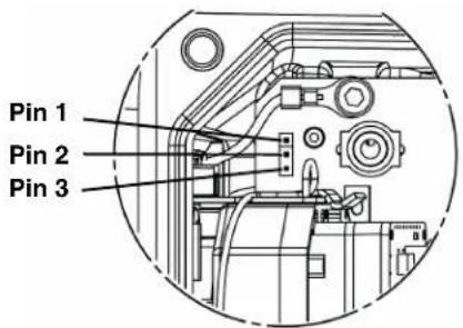
text_image
Pin 1 Pin 2 Pin 3Figure 1-8: Lens Heater Jumper Setup
μhe FC-Series _'mer' is shipped from the f'_tory with the supplement'l lens he'ter °FF (jumper pins 2 'nd 3). μo en'ble the Supplement'l Lens He'ter, move the he'ter jumper to °N (jumper pins 1 'nd 2). Proper operation of the Supplement'l Lens He'ter requires th't the _'mer' be powered by 24 V', >16Vd_ or P°E+.
It is important to note that the supplement's lens he's ter is not required for operation in 'll _old temperatures. The system operates to spe_ifi_tion 'nd produ_es highest quality images without the Supplement' Lens He'ter. Cont'_t FLIR μe_hni_1 Support for 'dition'l inform'tion (888-747-3547 inside the US).
1.6.3 9ench Testing
Note
If the _mer' is to be mounted on 'pole or tower or other h'rd-to-re'_h lo_tion, it m'y be 'good ide' to _onne_t 'nd oper'te the _mer' 's 'ben_h test 't ground level prior to mounting the _mer' in its fin'l lo_tion.
Conne_t the power, Ethernet, 'nd video, 'nd _onfirm th't the video _'n be disp'yed on ' monitor when the power is turned on. For _onfigur'tion 'nd b'si_ setup inform'tion using the onbo'rd web server, refer to C'mer' Ben_h μest, pg. 2-2 for spe_ifi_det'ils.
1.6.4 Analog Video Connections
μhe prim'ry 'n'log video _onne_tion of the_'mer' is 'BNC _onne_tor. Altern'tively, the_'mer' 'Iso provides 'n RCA 'n'log video _onne_tor. 'only one or the other _onne_tion should be used on' perm'nent b'sis to ensure 'dequ'te video qu'lity. μhe RCA _onne_tion 'llows the inst'ller to tempor'rily monitor the video output, without dis_onne_ting the prim'ry _onne_tion.
μhe video _'ble used should be r'ted 's RG-59/U or better to ensure ' qu'lity video sign'l.
Note
Insert the _'bles through the _'ble gl'nds on the en_losure before termin'ting 'nd_onne_ting them. In gener'l, termin'ted_onne_tors will not fit through the _'ble gl'nd. If 'termin'ted_'ble is required, it is possible to m'ke '_le'n 'nd singul'r _ut in the gl'nd se'l to inst'll the _'ble into the gl'nd se'l.
1.6.5 Connecting Power
μhe _mer' _n be powered with ' _onvention'l ' _ or d_ power supply, r'ther th'n PoE+. Prior to m'king 'ny _onne_tions, ensure the power supply or _ir_uit bre'ker is swit_hed off.
Table 1-2: Power Connections
| 1 Ch'ssis | |
| 2 ×AC/×DC - | |
| 3 ×AC/×DC + |
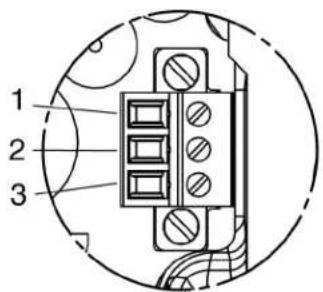
text_image
1 2 3Figure 1-9: Power Connector
μhe power _'ble supplied by the inst'ller must use wires th't 're suffi_ient size g'uge for the supply volt'ge 'nd length of the _'ble run, to ensure 'dequ'te _urrent _'rrying _'p'ity (18 AWG re_ommended for most inst'll'tions). Alw'ys follow lo_'I building/s'fety _odes.
Note
μhe termin'l _onne_tor for power _onne_tions will ' _ept 16 AWG to 24 AWG wire size.
μhe power _onne_tor plug m'y be removed for _'ble inst'll'tion. After the plug is re'tt'_hed to the bo'rd, re-tighten the s_rew termin'ls.
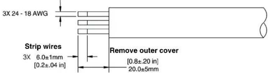
text_image
3X 24 - 18 AWG Strip wires 3X 6.0±1mm [0.2±.04 in] Remove outer cover [0.8±.20 in] 20.0±5mmFigure 1-10: Power Cable (3 conductor)
μhe_'mer' itself does not h've 'n on/off swit_h. Gener'lly the FC->eries_'mer' m'y be _onne_ted to '_ir_uit bre'ker 'nd the _ir_uit bre'ker will be used to 'pply or remove power to the_'mer'. If power is supplied to it, the_'mer' will be powered on 'nd oper'ting.
1.6.6 >thernet
Conne_t 'shielded _t5e/6 Ethernet _'ble to the RJ-45 j'_k. If using PoE+ to supply power to the _'mer', _onne_t the other end of the Ethernet to 'PoE+ swit_h or PoE+ inje_tor. °therwise _onne_t the Ethernet to 'network swit_h.
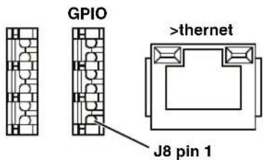
text_image
GPIO >thernet J8 pin 1Figure 1-11: GPIO and >thernet Connectors
1.6.7 GPIO Connections
Input Signal—μhe _'mer' _'n re_eive 'n extern'l input sign'l on '__essory _onne_tor J8 pins 4 'nd 5 when these pins 're _onne_ted by 'n extern'l swit_h _losure. Pin 5 is _onne_ted to the _'mer"s intern'l +5× power supply 'nd must not be dire_tly _onne_ted to _h'ssis ground. Pin 4 is _onne_ted to the intern'l digit'l ground.
While prote_tion for st'ti_dis_h'rge h's been pl'_ed on these pins, _'re should be used in m'king_onne_tions to the pins to 'void_onne_tions to other volt'ges or power sour_es outside the _'mer'.
- Insert wires 2. Snip wire through plug and close cage
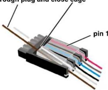
text_image
cough plug and close cage pin 1Figure 1-13: GPIO and >thernet Connectors
Output Signal—μhe _mer_ _n provide '_ont'_t _losure output on ' essory _onne_tor J8 pins 2 'nd 3 when 'n extern'l volt'ge is supplied to these pins. When open the resist'n_e between pins 2 'nd 3 is gre'ter th'n 100 K ohm. When _losed the resist'n_e between pins 2 'nd 3 is less th'n 200 ohm. μhe m'ximum re_ommended pe'k volt'ge between the pins is 6 volts. μhe m'ximum re_ommended _urrent 'llowed between the pins is 30 mA (0.03 A).
Table 1-3: GPIO Connections - J8
| Pin Connection Notes | ||
| 1 Chssis ground | ||
| 2 GP ^ 'ut When the _'me | sends 'n output sign'l, 'nextern'l volt'ge on one pin is 'pplied to the other pin. | |
| 3 GP ^ 'ut | ||
| 4 Digit'l ground | When these pins 're_onne_ted extern'lly, the _'mer' re'ds this 's 'n input sign'l. | |
| 5 +5x | ||
| 6 Chssis ground | ||
Note
μhe termin'l plug supplied for GPI°_onne_tions uses str'nded 26 AWG wire size (1 mm di'meter in_luding insul'tion) using spring-'ge 'nd pier_e _ont'_t te_hnology.
1.6.8 Camera Grounding
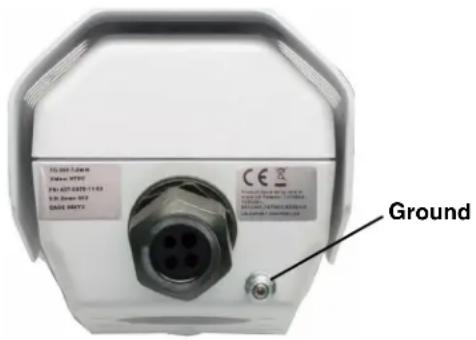
Ensure the _mer' is properly grounded. F'ilure to properly ground the _mer' _n le'd to perm'nent d'm'ge to the _mer'. μypi_'l to good grounding pr'_ti_es, the _mer' _h'ssis ground should be _onne_ted to the lowest resist'n_e p'th possible. μhe _mer' h's 'n extern'l ground _onne_tion on the outside b'_k of the _mer'. FLIR requires 'grounding str'p 'n_hored to the grounding lug 'nd _onne_ted to the ne'rest e'rth-grounding point.
If, during inst'll'tion, 'ny ground _onne_tions inside the _mer' 're dis_onne_ted, they should be re_onne_ted prior to _losing the _mer'.
text_image
FLG 0001-5.04 V/Max: 95702 FN: 627-8420-11163 D: 200000000 GA05 00072 CE GroundFigure 1-15: Camera Ground Connection
1.7 Rear Access Cable Gland Sealing
Proper inst'll'tion of _'ble se'ling gl'nd 'nd use of 'ppropri'te el'stomer inserts is _riti_'l to long term reli'bility. C'bles enter the re'r of the _'mer' mount en_losure through 'liquid-tight _ompression gl'nd.
Le've the gl'nd nut loosened until 'll_'ble inst'll'tion h's been _ompleted, 'nd ensure the m'nuf'_turer's re_ommended_'ble bend r'dius is observed within the en_llosure. Do not forget to tighten the_'ble gl'nd se'l nut to ensure 'w'tertight se'l 'nd provide str'in relief for_'bles.
Cable Gland Seal Inserts
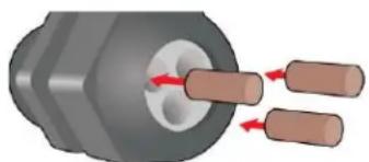
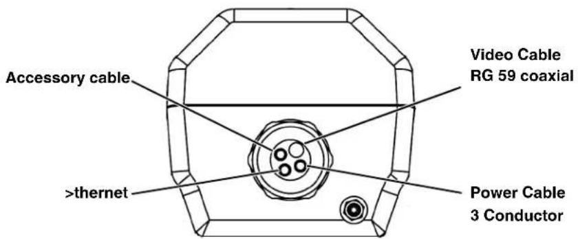
μhe FC->eries _'mer' _omes with 'single 3/4" <Pμ _'ble gl'nd inst'llled in the _'mer', with 'four-hole gl'nd se'l insert. μhe gl'nd in_ludes 'se'ling w'sher 'nd is se_ured to the _'mer' with 'nut on the inside of the en_losure. μhe gl'nd insert h's one hole for the RG-+9/= 'n'log video _'ble (the l'rger hole) 'nd three more for 'power _'ble, Ethernet _'ble, 'nd 'n ' essory _'ble (not used 't this time).
Any of the holes whi_h 're not used for _'bles should be filled with one of the hole plugs (supplied). Inst'll the _'bles through the _'ble gl'nd so th't the _'bles line up with the _onne_tions inside the _'mer'.
natural_image
Mechanical component with two cylindrical pins inserted into a circular housing (no text or symbols visible)
Note
Insert the _'bles through the _'ble gl'nds on the en_losure before termin'ting 'nd _onne_ting them. In gener'l, termin'ted _onne_tors will not fit through the _'ble gl'nd. If ' termin'ted _'ble is required, it is possible to m'ke '_le'n 'nd singul'r _ut in the gl'nd se'l to inst'll the _'ble into the gl'nd se'l.
μo ensure 'w'ter tight se'l when using the supplied re'r _'ble gl'nd, _'ble dimensions must be within the minimum 'nd m'ximum 's des_ribed in μ'ble 1-4.
If non-st'nd'rd _'ble di'meters 're used, 'n 'ppropri'te _'ble gl'nd 'nd insert should be used to fit the desired _'ble 'nd to fit the hole in the en_losure. FLIR >systems, In_. does not provide _'ble gl'nd inserts other th'n the insert supplied with the system.
If 'repl'_ement is used, inspe_t 'nd inst'll the gl'nd fitting in the b'_k _over with suit'ble le'k se'l or se'l'nt 'nd tighten to ensure w'ter tight fittings. μo fit the 1.0+0 in. (26.7 mm) hole in the en_losure, the thre'd size should be 3/4" <Pμ or M2+. μhe gl'nd should be inst'lled with 'se'ling w'sher (for ex'mple, Hey_o P<3261 or equiv'ent) between the gl'nd 'nd the extern'l surf'_e of the en_losure.
text_image
Accessory cable
thernet Video Cable RG 59 coaxial Power Cable 3 Conductor
Figure 1-16: Cable Routing
Table 1-4: Rear >xit Cable Min/Max Dimensions
| Cable Minimum Maximum Notes | |||
| Power (3_ondu_tor), Ethernet, A_essory _'bles | 4.+ mm[0.178 in] | +.2 mm[0.20+ in] | When using the _on_e'led _'ble w'll mount (P< 4129742), _'bles _'n h've ' m'ximum di'meter of 10 mm [0.394 in] |
| RG +9 xideo _'ble | +.3 mm[0.209 in] | 6.4 mm[0.24+ in] | |
1.8 Concealed Cable Mount Accessory
Do not route _'bles through the bottom of the _'mer' unless the _on_e'led _'ble w'll mount (P<4129742) is used. μhe w'll mount is spe_ifi_Illy designed for the _'mer' 'nd 'llows the opening to se'l properly. When using the _on_e'led _'ble w'll mount, _'ble dimensions must be within the minimum 'nd m'ximum 's des_ribed in μ'ble 1++.
Table 1-5: Cable Min/Max Dimensions using Concealed Cable Wall Mount (PN 4129742)
| Cable Minimum Maximum Notes | |||
| Power (3_ondu_tor), Ethernet, A_essory _'bles | 4.+ mm[0.178 in] | 10 mm[0.394 in] | When using the re'r exit_'ble gl'nd, the m'ximum di'meter is +.2 mm [0.20+ in] |
| RG +9 xideo _'ble | +.3 mm[0.209 in] | 10 mm[0.394 in] | |
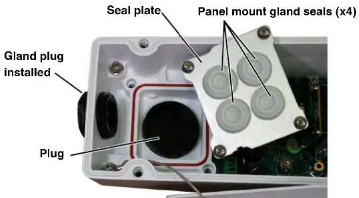
Proper inst'll'tion of the se'l pl'te 'nd p'nel mount gl'nd se'ls is _riti_'I to long term reli'bility. C'bles enter the bottom of the _mer' en_losure through the se'l pl'te 'nd p'nel mount gl'nds. Be sure to insert e'_h_'ble through its p'nel mount gl'nd on the se'l pl'te before termin'ting them (_onne_tors will not fit through the gl'nd). Ensure the m'nuf'_turer's re_ommended _'ble bend r'dius is not ex_eeded within the en_losure.
Prepare the Camera
tep 1 =se '3 mm hex key to loosen the four _'ptive s_rews 'nd remove the top _over 's des_ribed 'bove.
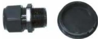
tep 2 Remove the re'r _'ble gl'nd 'nd repl'_e it with the _'ble gl'nd plug. =se the g'sket 'nd nut th't were removed with the _'ble gl'nd.
tep 3 =se ' 3 mm hex key to loosen the four _'ptive s_rews 'nd remove the se'l pl'te, o-ring, 'nd plug.
natural_image
Two black plastic connectors: a threaded connector and a circular cover (no text or symbols visible)Figure 1-18: Removed Parts
text_image
Seal plate Panel mount gland seals (x4) Gland plug installed PlugFigure 1-17: Seal Plate Removed
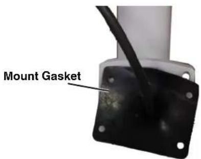
tep 4 Inst'll the w'll mount (P<4129742) to the w'll 'nd pull the_'ble(s) through the mount. Cut 'sm'll _ross-slit in the bl'_k mount g'sket 'nd push the_'ble(s) through the g'sket. Pull the_'ble(s) through the opening in the bottom of the_'mer'. A single Ethernet_'ble is shown in the im'ges.
tep + >e_ure the_'mer' to the mount using four M+ x 0.8 thre'ded f'steners to the bottom of the_'mer'. =se Lo_tite 222 low strength thre'd lo_ker for the mount f'steners.
tep 6 As needed, _le'n the o-ring 'nd the o-ring groove in the bottom of the _mer' using isotropy 'l_ohol 'nd press the o-ring into its groove.
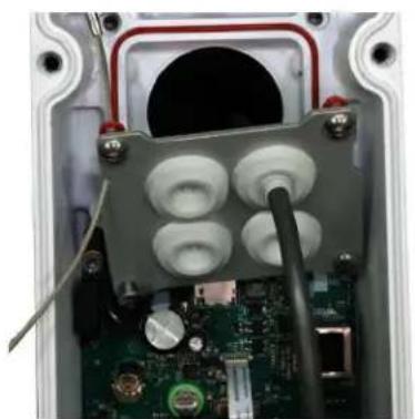
tep 7 For e'_h _'ble, pun_h hole in the _enter of 'gl'nd se'l from the top using the 3 mm hex key. Insert the _'ble from the bottom though the hole.
tep 8 Pl'e the gl'nd pl'te b'_k into position 'nd tighten the four 3 mm _'ptive s_rews using ' torque v'lue of 1.8 n-m (16.0 in-lbs).
tep 9 Che_k the length of e'_h_'ble to ensure 'n 'ppropri'te bend r'dius 'nd termin'te the_'ble.
text_image
Mount GasketFigure 1-19: Camera Mount
natural_image
Interior view of an electronic device showing a circuit board, capacitors, and wiring (no visible text or symbols)Figure 1-20: Cable through Seal Plate
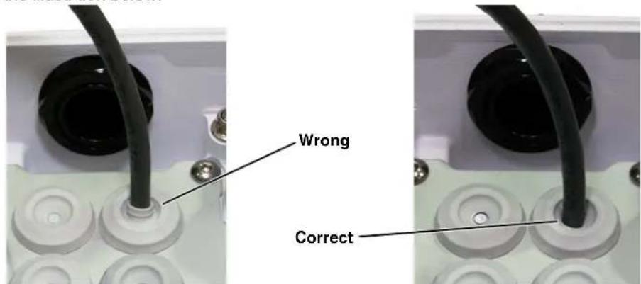
tep 10 Push the _'ble b'_k through the gl'nd se'l so th't the se'l is extended down not up, 's shown in the illustration below.
text_image
Wrong Correcttep 11 Conne_t the _'bles 's indi_'ted in Figure 197 on p'ge 197. Ensure th't 'ny ground wire th't w's removed during inst'll'tion is re_onne_ted. Repl'_e the _over 'nd tighten the four 3 mm hex s_rews to 1.8 n9m (16.0 in9lbs).
Caution!
When repl'ing the _over, m'ke sure the ground wire between the _over 'nd the _mer' body is _ompletely inside the o9ring groove. If the wire is pin_hed between the _over 'nd the b'se, the _mer' will not be se'led 'g'inst w'ter ingress 'nd _ould be d'm'ged.
tep 12 =sing the hex key th't is in_luded with the _on_e'led_'ble mount, loosen the b'll joint on the bottom of the mount, position the_'mer' 's required,'nd then re9tighten the b'll joint.
1.9 Camera specifications
| Camera Models FC-Series S, FC-Series R | |
| Camera Platform Type Fixed | |
| Composite Video NTSC or PAL | |
| Thermal Camera | |
| Array Format 324x256 (25 μm pixel pitch)336x256, 640x480 (17 μm pixel pitch) | |
| Detector Type Long-Life, Uncooled VOx Microbolometer | |
| Effective Resolution 76,800 | |
| Field Of View (Focal Length) for available FC-Series S camera lens configurations. | FC-363 S = 63° × 50° (7.5 mm)FC-348 S = 48° × 39° (9 mm)FC-334 S = 34° × 28° (13 mm)FC-324 S = 24° × 19° (19 mm)FC-313 S = 13° × 10° (35 mm)FC-309 S = 9° × 8° (35 mm)FC-690 S = 90° × 69° (7.5 mm)FC-669 S = 69° × 56° (9 mm)FC-645 S = 45° × 37° (13 mm)FC-632 S = 32° × 26° (19 mm)FC-618 S = 18° × 14° (35 mm) |
| Field Of View (Focal Length) for available FC-Series R camera lens configurations. | FC-334 R = 34° × 28° (13 mm)FC-324 R = 24° × 19° (19 mm)FC-645 R = 45° × 37° (13 mm)FC-632 R = 32° × 26° (19 mm) |
| Spectral Range 7.5 to 13.5 μm | |
| Lens Athermalized, focus-free | |
| General | |
| Weight 4.8 lb (2.2 kg) with sun shield | |
| Dimensions (L,W,H) | 11.1" x 5.1" x 4.5" with sunshield,(282 mm x 129 mm x 115 mm) |
| Input Voltage - dc | 14 - 32 Vdc |
| Input Voltage - ac | 18 - 27 Vac |
| Input Voltage - PoE+ | IEEE 802.3af-2003 standard or higher power,IEEE 802.3at-2009 standard |
| Power Consumption | 5 W nominal at 24 Vdc8 VA nominal at 24 VacPeak at 24 Vdc: 21 W with supplemental lens heaterPeak at 24 Vac: 29 VA with supplemental lens heater |
| Mounting Provisions | Two 1/4-20" threaded holes on top and bottom,1" spacing along center line front to back.Four M5 threaded holes bottom,40 mm x 62 mm (1.6 in x 2.4 in) spacing square. |
| Shipping weight | 6.1 lbs (2.8 kg) |
| Shipping Dimensions 14.375"(L) x 7 | 375"(W) x 7"(H) |
| >nvironmental | |
| IP r'ting (dust 'nd w'ter ingress) IP66 & IP67 | |
| Oper'ting temper'ture r'nge -50 °C to | 70 °C (-58 °F to 158 °F) continuous-40 °C to 70 °C (-40 °F to 158 °F) cold st'rt |
| Stor'ge μemper'ture r'nge -55 °C to 8 | 5 °C (-67 °F to 185 °F) |
| Humidity 0-95% rel'tive | |
| Shock IEC 60068-2-27 10 g shock pulse with ' 11ms h'lf-sine profile | |
| Vibr'tion MIL-SμD-810F | |
| Approv'ls FCC P'rt15, Subp'rt B, Cl'ss B,EN 55022 Cl'ss B, EN 50130-4,EN60950 | |
2 9asic Operation and Configuration
μhis _h'pter provides b'si_inform'tion on how to oper'te ' new_'mer' th't h's not yet been _onfigured3 A ben_h test _'n be used to verify_'mer' operation before the_'mer' is _onfigured for the lo-'l network3 μhis _h'pter 'Iso provides b'si_ _onfigur'tion inform'tion3
μhe _mer' h's 'n Ethernet _onne_tion th't llows stre'ming video over 'n IP network 's well 's _onfigur'tion 'nd _ontrol of the _mer' 83 It is possible to stre'm video 'nd _ontrol the _mer' 's it is from the f'_tory, without m'king 'ny _onfigur'tion _h'nges3 However in most _ses the _mer' will h've 't le'st some _onfigur'tion _h'nges to 'llow it to _onne_t with other devi_es or other video m'n'gement systems on the existing network3
°n_e the_'mer' is _onne_ted to ' network 'nd powered on, the user_'n perform ' ben_h test by using ' web browser 4 to view the video 'nd _ontrol the_'mer', or by using the FLIR >ensors M'n'ger (F>M7 softw're3 μhe F>M softw're_'n be downlo'ded from the FLIR web site ( http://support3flir3_om/7 for free 'nd does not require ' li_ense to use3 Refer to the F>M =ser M'nu'l for det'ils 'bout using the softw're; the m'nu'l is 'v'il'ble from the Windows >t'rt menu on_e the softw're is inst'llled3
Getting the _'mer' IP interf'_e set up 'nd working m'y require ' level of f'mili'rity with m'n'ging IP networks th't is new to m'ny se_urity profession'ls3 Prior to _onfiguring the IP interf'_e 'nd stre'ming video p'r'meters, be f'mili'r with how to m'n'ge 'nd _onfigure the other equipment in the network (for ex'mple, 'ny PC or devi_e th't will _onne_t to the _'mer', 'ny router or firew'll th't will _rry the IP tr'ffi_, 'nd so on73 FLIR te_hni_'l support _'n only provide limited support in this reg'rd3
2.1 IP Camera, ONVIF Profile S Compliant
μhe FC9>eries _mer' is 'n IP _mer' with 'mi_ropro_essor inside th't runs the _mer' firmw're3 When the _mer' is _onne_ted to the network it fun_tions 's ' server; it provides servi_es su_h 's _mer' _ontrol, video stre'ming, network _ommuni_tions, 'nd geo9referen_ing _p'bilities3 μhe _ommuni_tions proto_ol used is 'n open, st'nd'rds9b'sed proto_ol th't llows the server to _ommuni_te with 'video m'n'gement _lient, su_h 's FLIR >ensors M'n'ger or with 'third9p'rty ×M> _lient, in_luding systems th't 're _omp'tible with °<×IF Profile >3
μhere 're two m'in _omponents to the server softw're3 °ne is ' web server known 's the web tool or web interf'_e th't listens on the network for web browser requests, 'nd is used for the initi'l ('nd perh'ps ongoing or o__ 'sion'l7 _onfigur'tion _h'nges to the server3 μhe web tool 'Iso 'llows the user to view video 'nd to oper'te the _mer'3
μhe other pro_ess, known 's the
2.1.1 Server Configuration
In gener'l, it m'y be ne_ess'ry for the inst'ller to m'ke ' limited number of _onfigur'tion _h'nges to the server, su_h 's setting the IP _ommuni_'tion p'r'meters3 For ex'mple, e'_h_'mer' _omes from the f'_tory with the s'me def'ult IP 'ddress, so 'dding more th'n one_'mer' to 'n IP network requires
e'_h_'mer' to be _onfigured with ' different IP 'ddress, 't ' minimum. °n the other h'nd, m'ny of the _onfigur'tion p'r'meters will rem'in un_h'nged from the f'_tory def'ult settings.
2.2 9asic Test and Configuration Steps
Assuming the existing network uses IP 'ddresses th't 're unique 'nd different th'n the def'ult 'ddress on the_'mer', _onfiguring the_'mer' for IP _ommuni_'tions gener'lly involves the following steps:
tep 1 Conne_t the Ethernet port to 'n IP network th't is isol'ted from the existing _mer' network (for ex'mple, ' st'nd'lone swit_h)
tep 2 Conne_t ' PC or l'ptop to the s'me network
tep 3 μempor'rily set the IP 'ddress of the PC or l'ptop to be _omp'tible with the f'_tory network 'ddress of the _mer' (for ex'mple, 192.168.250.1)
step 4 Perform 'ben_h test of the_'mer' using 'web browser or F>M, prior to m'king 'ny p'r'meter _h'nges (this step is option'l but re_ommended)
tep 5 Configure the _'mer' settings, su_h 's IP 'ddress, _'mer' d'te/time, se_urity settings, °tep 6 >'ve the _onfigur'tion _h'nges 'nd rest'rt the server
tep 7 Conne_t the_'mer' to the existing network 'nd test the_'mer'
tep 8 M'ke ' b'_kup of the new _onfigur'tion
2.3 Camera 9ench Test
μhe_'mer' offers both 'n'log video 'nd IP video, 'nd sin_e the_'mer'_'n be powered by PoE+ or by '_onvention'l power supply, there 're sever'l w'ys to ben_h test the_'mer'. It is re_ommended th't the inst'ller test the_'mer' using the s'me type of _onne_tions 's in the fin'l inst'lltion.
Even if using 'n'log video 'nd _onvention'l power in the fin'l inst'll'tion, it is 'good ide' to test the IP _ommuni_tions when performing the ben_h test. If 'ny im'ge 'djustments 're ne_ess'ry, they _'n be done using 'web browser over the IP _onne_tion, 'nd s'ved 's power-on default settings.
With the _mer' powered up, 'n'log video _'n be tested 't either the B<C_onne_tor or the RCA_onne_tor. Conne_t the _mer' to 'video monitor 'nd_onfirm the live video is disp'yed on the monitor.
If using ' _onvention'l power supply, _onne_t the _'mer' to ' network swit_h with 'n Ethernet _'ble, 'nd _onne_t ' PC or l'ptop to the swit_h 'lso. =se ' web browser to ' ess 'nd test the _'mer 's des_ribed below, 'nd if ne_ess'ry m'ke _onfigur'tion _h'nges prior to inst'll'tion. °n_e the ben_h test is _omplete, use the web browser to m'ke _onfigur'tion _h'nges 's needed (for ex'mple, set the IP 'ddress to 'n 'ddress th't is _omp'tible with the existing network).
2.3.1 Testing IP Communications
μhe FC->eries _mer' is shipped with 'n IP 'ddress set to 192.168.250.116. >et the PC or l'ptop network 'd'pter to '_omp'tible IP 'ddress, for ex'mple: 192.168.250.1 with 'netm'sk of 255.255.255.0. If unsure how to set the IP 'ddress on the PC or l'ptop, refer to >etting the IP 'ddress on ' Windows PC, pg. 2-23.
=se ' web browser to _onne_t to the_'mer' 's des_ribed below, 'nd _onfirm the video_'n be viewed in the browser. Inst'll F>M 'nd use it to _onne_t to the_'mer' 'nd _onfirm the video_'n be
viewed 'nd the _mer' _n be _ontrolled (see se_tion 2.3.4 “=sing F>M” on p'ge 2-7). F>M is espe_i'lly useful for _onfirming the fun_tions of the GPI°_onne_tions.
2.3.2 Log in to the Camera Web Page
With ' web browser, it is possible to log in to the _'mer' using one of three =ser <'mes: user, expert, 'nd admin. By def'ult, the p'sswords 're: user, expert, 'nd fliradmin, respe_tively. μhe login p'sswords should be _h'nged to prevent un'authorized log ins (refer to B'si_C'mer'____ Configur'tion, pg. 2-10).
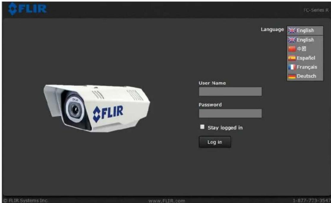
'pen ' web browser 'nd enter: http:\192.168.2+0.116. μhe login s_reen with ' pi_ture of the _mer' will 'ppe'r. A pull-down list in the upper right 'llows the user to sele_t ' l'ngu'ge option. Enter user for the =ser <'me 'nd user for the P'ssword, 'nd _li_k Log in.
text_image
FLIR FC-Series R Language English English 中国 Español Français Deutsch User Name Password Stay logged in Log in © FLIR Systems Inc. www.FLIR.com 1-877-773-3547Figure 2-1: Camera Web Page Login Screen
μhe user login _'n be used to do the initi'l ben_h test of the _'mer'. μhe expert login _'n be used to m'ke b'si _onfigur'tion _h'nges su_h 's setting the IP 'ddress. μhe admin login is used for more 'dv'n_ed _onfigur'tion _h'nges, 'nd is des_ribed in Adv'n_ed Configur'tion, pg. 3-1.
Note
μwo web sessions _'n be '_tive 't on_e. An in'_tive session will be logged out 'fter 20 minutes.
2.3.3 Live Video Page
μhe Live Video p'ge will be displ'yed, with ' live im'ge from the _ 'mer' on the left p'rt of the s_reen. <ext to the FLIR logo 'long the top of the s_reen 're some menu _hoi_es, in_luding Live Video (the red text indi_'tes it is sele_ted), Help, 'nd Log out. μhe expert 'nd admin logins provide 'ddition'l menu _hoi_es.
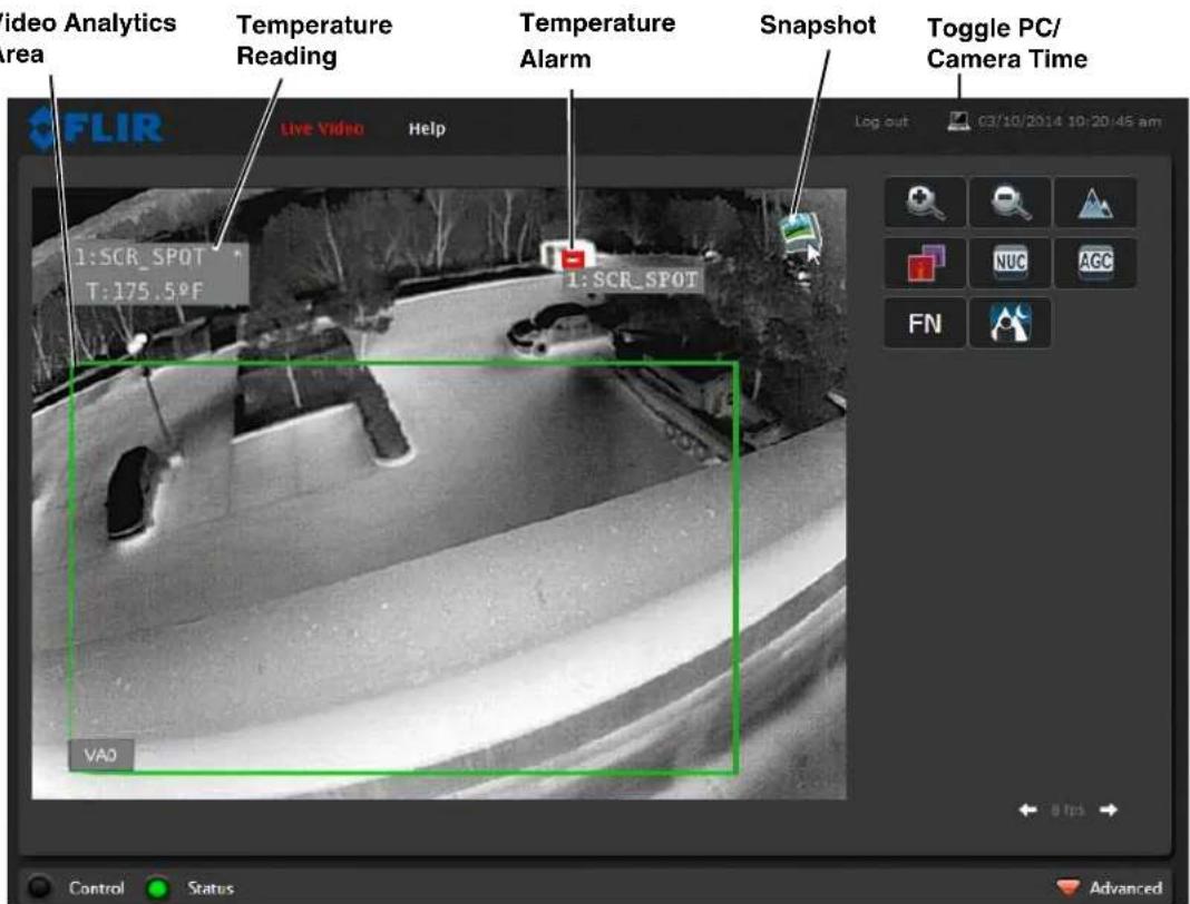
text_image
Video Analytics Area Temperature Reading Temperature Alarm Snapshot Toggle PC/ Camera Time FLIR Live Video Help 1:SCR_SPOT T:175.5°F 1: SCR_SPOT VAO Control Status Advanced
Figure 2-2: Live Video Web Page
If the live video is not dispI'yed, refer to roubleshooting ips, pg. 2918. In the lower right of the web p'ge there is ' fr'me r'te sele_tor. his sele_tor 'llows the user to _h'nge the r'te 't whi_h the fr'mes 're dispI'yed in the browser. his r'te _ontrols the user's own web browser only, 'nd does not 'ffe_t the video stre'ms to other users or to 'n <xR. For slow _ommuni_'tion links, if there is ' problem dispI'ying the video im'ge, it m'y help to slow down the fr'me r'te.
Help
At the top of the p'ge, the Help menu displ'ys softw're version inform'tion. μhis p'ge h's inform'tion 'bout the _mer' in_luding h'rdw're 'nd softw're revision numbers, p'rt numbers, 'nd seri'l numbers. If it is ne_ess'ry to _ont'_t FLIR μe_hni_'l >upport for 'ssist'n_e, it will be helpful to h've the inform'tion from this p'ge (su_h 's >oftw're xersion) on h'nd.
Log out
=se this button to dis_onne_t from the_'mer' 'nd stop the displ'y of the video stre'm. If 'web session is in'_tive for 20 minutes, it will be stopped 'nd it will be ne_ess'ry to log in 'g'in.
Toggle PC/Camera time
Use this button to display either the PC time or the c'mer' time.
Temperature—FC-Series R camera only
μhe FC-Series R c'mer' c'n provide temper'ture me'surements, the precision of which depend on m'ny f'ctors, including the 'mbient temper'ture, the dist'nce to the object, 'nd emissivity, 'n indic'tion of how well ' p'rticul'r m'teri'l r'di'tes energy. By def'ult, box 'nd spot me'surement regions 're setup ne'r the center of the video im'ge to 'l'rm ne'r 90 °F (body temper'ture). Refer to μemper'ture Monitoring Setup (FC-Series R c'mer' only), pg. 3-10._
Camera Control and Status
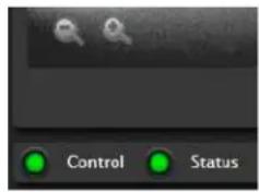
In the lower left of the screen 're two indic'tor "lights": Control 'nd St'tus. Initi'lly the Control light is off, 's in the im'ge 'bove, indic'ting the user is not 'ble to control the c'mer' immedi'tely. When multiple users 're connected to 'c'mer', only one user 't' time c'n issue comm'nds to the c'mer'. If 'nother user h's control of the c'mer', the Control light is yellow.
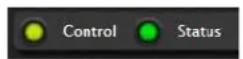
A user is 'ble to request control of the c'mer' by clicking on the yellow or bl'ck "light", or simply by sending 'comm'nd to the c'mer'. For example, move the cursor over the video 'nd select the "Zoom In" control (m'gnifying gl'ss with "+" ) th't 'ppe'rs in the lower left of the screen. μhe St'tus light m'y turn off tempor'rily while w'iting for the response from the c'mer'. After short p'use, the Control light should turn green. Observe wh't h'ppens to the im'ge when the "Zoom In" control is clicked sever'l times. Be p'tient, there m'y be 'slight del'y between e'ch comm'nd while the browser w'its for 'response from the c'mer'.
text_image
Control StatusIf 'comm'nd is sent to the c'mer' when the user does not h've control, the comm'nd will not be executed, 'nd it is necessary to send the comm'nd 'g'in once the light is green.
In 'ddition, when the cursor is moved over the video, ' sn'pshot button 'Iso 'ppe'rs in the upper right of the screen. After clicking the sn'pshot button, the video im'ge is s'ved 's ' jpg file 'nd the browser will provide prompts depending on which browser is being used.

Web Control Panel
μhe control buttons on the right side of the p'ge provide 'w'y to control the c'mer' in 'limited number of w'ys. When the mouse cursor is positioned over 'button,' tool tip is dispI'yed.
μhis s'me web interface is used with v'rious FLIR therm'l c'mer's—some 're fixed, such 's the FC-Series c'mer's, 'nd some 're p'n/tilt c'mer's. As ' result, different buttons in the control p'nel will 'ppe'r for different FLIR c'mer's.
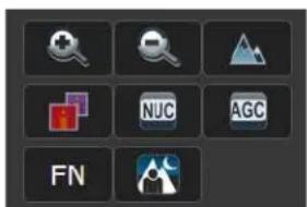
text_image
Grid of nine labeled icons including magnifying glass, document, triangle, NJC, AGC, FN, and camera symbolμhe following buttons 'ppe'r for the FC-Series c'mer's:

Digit'l Zoom
μthese buttons zoom the disp'yed video. μhe zoom st'te ('nd other c'mer' settings) c'n be s'ved in the IR Setup p'ge (refer to S've Settings, pg. 3-3). μhis will 'llow the c'mer' to ret'in the desired zoom st'te (field of view) 'fter the power is cycled.

μoggle Pol'rity
his button _h'nges the pol'rity of the 'ssigned _olors to the different temper'tures in 's_ene. In the bl'_k 'nd white p'lette for ex'mple, hot obje_ts 're displ'yed 's white 'nd _old obje_ts 's bl'_k, or vi_e vers'.

μoggle P'lette
μhis button _'uses the _'mer' to _y_le through six different look up t'ble (L=μ) _olor p'lettes. Depending on the subje_ts viewed, one _olor p'lette m'y be prefer'ble to the others. μhe μoggle Pol'rity button 'llows' __ess to six more p'lettes (refer to Mis_ (Lookup____ μ'ble), pg. 3-3).

Perform IR <=C C'libr'tion
his button _'uses the _'mer' to perform ' <on-=niformity Corre_tion oper'tion (refer to lm'ge freezes moment'rily, pg. 2-18).

μoggle Autom'ti_G'in Control (AGC)
his button _'uses the _'mer' to _y_le through + different AGC options th't use ' _ombin'tion of settings to produ_e different _onfigur'tions th't _ould improve the video im'ge for ' given set of _onditions.

μoggle >_ene Preset
μhis button _'uses the _'mer' to _y_le through + different im'ge settings. μhe >_ene Presets _'use the im'ge brightness 'nd _ontr'st to 'djust. Depending on the time of d'y, we'ther, 'nd other _onditions, one >_ene Preset m'y be prefer'ble to the others.

Fun_tion
μhe FC->eries _'mer's h've 'ddition'l fe'tures or fun_tions whi_h _'n be ' _essed using 'n extr' numeri_ fun_tion keyp'd. It is possible to _re'te _customized _'mer' fun_tions through ' "m'_ro" interf'_e whi_h _'n be progr'mmed through "ML _omm'nds. Cont'_t FLIR μe_hni_/'l >upport for inform'tion 'bout the <exus "ML-B'sed Control Interf'_es.
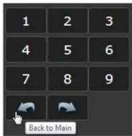
text_image
1 2 3 4 5 6 7 8 9 Back to Main
When the Fun_tion button is sele_ted, the keyp'd _h'nges to ' numeri_keyp'd providing progr'mmed fun_tions (1 - 9). >ele_t the b'_k 'rrow to return to the m'in keyp'd. >ome spe_ifi_'mer's_'n h've 'ddition'l fun_tions (10 - 18). μhe forw'rd 'rrow will'__ess these.
Refer to the following t'ble for definitions of the nine fun_tions 'v'il'ble to FC->eries _mer's. μhe video enh'n_ing options in some _ses m'y improve the video im'ge, 't le'st tempor'rily. °ver time or 's the environment _h'nges, the s_ene _ould _h'nge 'nd the resulting im'ge m'y no longer be optim'l.
| FN Function Description | |
| 1 En'ble EE | Edge enh'n_ement (EE) is 'n im'ge pro essing te_hnique th't enh'n_es det'ils by emph'sizing lines 'nd edges. It m'y be possible to see fine det'ils more e'sily in some s_enes, but it _ould 'Iso m'ke the im'ge somewhat more gr'iny or pixil'ted. |
| 2 Dis'ble EE | |
| 3 >AL-DRE Glob'l | μhe>_ene Ad'ptive Lo_'l Dyn'mi_ R'nge Enh'n_ement (>AL-DRE) 'lgorithm m'y improve the dyn'mi_ r'nge of some s_enes by 'd'ptive tone m'pping su_h th't the _ontents in both the d'rk 'nd bright regions 're visible. |
| 4 >AL-DRE Lo_'l | |
| + >AL-DRE °ff | |
| 6 >AL-DRE Low | |
| 7 >AL-DRE Medium | |
| 8 >AL-DRE High | |
| 9 >end μest Em'il | An em'il will be sent to the def'ult em'il list 's _onfigured in the <otifi_'tion Lists using the >MμP server defined in Msg >systems (refer to Msg >systems, pg. 2-13). μhe em'il will h've simply "μest" in the >ubje_t 'nd "FC->eries μest Em'il" in the mess'ge body. |
2.3.4 Using FSM
If F>M is not 'lre'dy inst'lled, downlo'd 'nd inst'll the l'test softw're from the FLIR support web site, http://support.flir_om/. Even if F>M will not be used in the fin'l inst'll'tion, it is 'good ide' to perform 'ben_h test with it,'s des_ribed below, prior to m'king _onfigur'tion _h'nges. °n_e the ben_h test is _omplete, use 'web browser to m'ke _onfigur'tion _h'nges 's needed (for ex'mple, set the IP 'ddress to 'n 'ddress th't is _omp'tible with the existing network).
μhe following provides 'brief des_ription of how to use F>M to _ontrol ' _mer' 'nd stre'm video from the _mer'. For more det'iled inform'tion on how to use F>M, refer to the FLIR Sensors Manager User Manual. °n_e the softw're is inst'llled, the m'nu'l is 'v'il'ble from the Windows >t'rt Menu.

2.3.5 Running FSM
Run the FSM softw're by double _li_king the FLIR Sensors M'n'ger i_on on the desktop, or _li_k on the Windows St'rt button 'nd sele_t Progr'ms > FLIR Sensors M'n'ger 4.0 > FLIR Sensors M'n'ger.
Initi'lly the FLIR Sensors M'n'ger spl'sh s_reen will be dispI'yed. After 'brief while, the FSM m'in window will 'ppe'r. A popup FSM Notifi_tion window m'y 'ppe'r in the lower right of the s_reen indi_ting th't no _mer's (servers) h've been dis_overed yet.
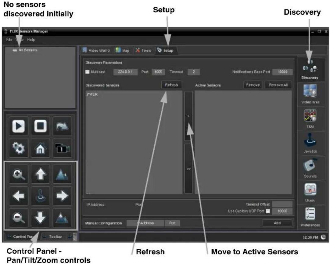
text_image
No sensors discovered initially FLIR Sensors Manager File View Help No Sensors Setup Discovery Video Wall 0 Vsp Tools Setup Discovery Parameters Multicast 224.0.9.1 Port 1005 Timeout 2 Notifications Base Port 10000 Discovered Sensors Refresh Active Sensors Remove Remove All *IFLR IP Address Port Timeput Offset Use Custom UDP Port 10000 Manual Configuration Address Port Add Preferences Control Panel - Pan/Tilt/Zoom controls Refresh Move to Active Sensors 12:30 PMμhe FLIR Sensors M'n'ger uses ' " _lient/server" 'r_hite_ture. μhe FSM softw're is _onsidered ' _lient, 'nd the _'mer's 're _onsidered servers or sensors. μhe Sensors P'nel in the upper left of the window indi'tes no sensors h've been dis_overed 'nd 'dded to the list of A_tive Sensors.
Cli_k on Setup, if required, then the Discovery button on the side p'nel to bring up the Dis_overy P'nel. μhe FSM softw're _'n 'utom'ti_ lly dis_over FLIR _'mer's on the network.
When the Dis_overy P'nel is disp'lyed, _li_k Refresh. μhe FLIR_'mer' should 'ppe'r in the list of Dis_overed Sensors, 'nd the 'sterisk in p'renthesis "(*)" indi_'tes the_'mer' h's not been 'dded to the list of A_tive Sensors on the right.
Cli_k on the _enter b'r ">" to move the_'mer' over to the list of A_tive >ervers.
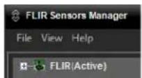
μhe n'me of the_'mer' should 'ppe'r in the >ensors P'nel, with 'green joysti_k i_on. By def'ult, the F>M softw're will 'utom'ti_'lly dis_over sensors in the network, _onne_t to the first_'mer' it finds, t'ke _ontrol of the_'mer', 'nd display' the video from the_'mer' in xideo W'll 0.
Cli_k on Video Wall 0 'nd _onfirm th't video is stre'med to the monitor 'nd it is possible to _ontrol the_'mer' using the zoom _ontrols in the Control Panel. For ex'mple, _li_k on the zoom button (m'gnifying gl'ss with +), 'nd the video will zoom in.
Video Wall 0

text_image
FLIR Sensors Manager File View Help FLIR (Active) Video Wall 0 Map Tools Setup Control Panel Toolbar 1:16 PMZoom In
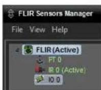
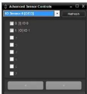
μo test the GPI° input 'nd output _onne_tors, _li_k on the tri'ngle to the left of the sensor n'me to exp'nd the sensor 'nd display the devi_es. μhen double-_li_k on the I° 0 devi_e to open up the Adv'n_ed >ensor Controls p'nel. μhe I° 0 Adv'n_ed >ensor P'nel _'n be used to m'nu'lly turn on or off the GPI° output, 'nd it
_'n be used to display if ' GPI° input is re_eived. μo turn on or off the output, _he_k the _he_kbox next to "1. [°] I° 1". >imil'ry, 'n input would be indi_ted with '_he_k next to "0. [I] I° 0".
More inform'tion 'bout _onfiguring 'nd using the GPI° 'I'm _'p'bilities is des_ribe in se_tion 3.2.1 ">ensor Menu" on p'ge 3-14.
text_image
Advanced Sensor Controls IO Sensor # [GEO] Refresh 0 [I] 10.0 1 [O] 10.1 2 3 4 5 6 72.4 9asic Camera Configuration
μhe following pro_edures des_ribe how to do the most _ommon ben_h test 'mer' _onfigur'tion steps, su_h 's setting the _mer' IP 'ddress 'nd hostn'me 'nd _h'nging the user p'ssword. μo m'ke these _h'nges, it is ne_ess'ry to login using the expert user '__ount. Addition'l setup 'nd _onfigur'tion options required 'fter the _mer' h's been inst'lled in its fin'l lo_tion 're des_ribed 'fter the b'si_ steps 're given, refer to Adv'n_ed Configur'tion, pg. 391._
2.4.1 Setup Menu

text_image
FLIR Live Video Setup Maintenance Helpμhe Setup menu is used for GE° >settings (L'titude 'nd Longitude lo_'tion), therm'l (IR) _'mer' settings, defining xideo An'lyti_s motion detetion zones, 'nd setting R'diometry temper'ture me'surement regions (FC9>eries R only). For 'ddition'l det'ils, refer to >etup Menu, pg. 391._
Adjustments to the IR settings should only be m'de by someone who h's expertise with therm'l _mer's 'nd ' thorough underst'nding of how the v'rious settings 'ffe_t the im'ge. In most inst'll'tions, the only _mer' settings needed 're 'v'il'ble from the Web Control p'nel on the Live xideo p'ge (>_ene Presets, Pol'rity, P'lettes, AGC, 'nd zoom). H'ph'z'rd _h'nges _'n le'd to im'ge problems in_luding '_omplete loss of video. Addition'l inform'tion is provided in μherm'l _lm'ge >etup, pg. 392.
When 'user logs in 's admin, ' _omplete Maintenance menu is 'v'il'ble (refer to Glob'l >settings, pg_3913). μhe Maintenance menu 'Iso provides ' ess to other _onfigur'tion options. For more inform'tion on setting or _h'nging other _mer' p'r'meters refer to the Nexus IP Camera Configuration Guide (FLIR Do_ #42790030900928).
2.4.2 Server Menu
When 'user logs in 's expert or admin, the Maintenance Server menus 're 'vil'ble. When the Server menu is sele_ted, the LAN Settings p'ge 'ppe'rs.
With most _onfigur'tion _h'nges through the Maintenance menu, it is ne_ess'ry to s've the _h'nges, then stop 'nd rest'rt the server to m'ke the _h'nges t'ke effe_t ^3 .
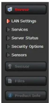
μhe b'si_'mer' _onfigur'tion steps 're' __essed through the Maintenance Server menu, using the menus on the left side of the p'ge. μhe LAN Settings, Services, 'nd Security Options sele_tions 're des_ribed below. μhe expert login h's '__ess to these Server p'ges, but will only see the se_urity settings for the user login.
text_image
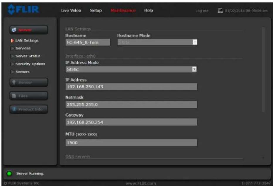
Server LAN Settings Services Server Status Security Options Sensors Sensor Files Product InfoLAN Settings: μhe LAN Settings p'ge _'n be used to set the hostn'me, def'ult g'tew'y, 'nd IP 'ddress for the _'mer'. A more des_riptive Friendly <'me (used by F>M) _'n be set from the Produ_t Info p'ge with the 'dmin login. μhe def'ult IP Address mode is st'ti_; the mode _'n 'Iso be set to DHCP.
text_image
FLIR Live Video Setup Maintenance Help Log OUT 01/02/2014 08:08:05 am LAN Settings Hostname Hostname Mode FC-645_R-Tom Interface: cfm0 IP Address Mode Static IP Address 192.168.250.143 Netmask 255.255.255.0 Gateway 192.168.250.254 MTU (1000-1500) 1500 DNS servers Server Running. © FLIR Systems Inc www.FLIR.com 1-877-773-3547When the LA< settings 're _h'nged 'nd the Save button is _li_ked, ' pop-up mess'ge will 'ppe'r to indi_'te the network interf'_e must be rest'rted.

text_image
Read Save Restart Network°n_e the IP 'ddress of the _'mer' is _h'nged, the PC m'y no longer be on the s'me network 'nd therefore m'y not be 'ble to __ess the _'mer' until the IP 'ddress on the PC is _h'nged 'Iso. For th't re'son, it m'kes sense to _h'nge the IP 'ddress 'fter m'king other _onfigur'tion _h'nges.
o reset the IP 'ddress to the f'_tory def'ult using 'loopb'_k_onne_tor, refer to Restoring the F'_tory >ettings, pg. 3-29.
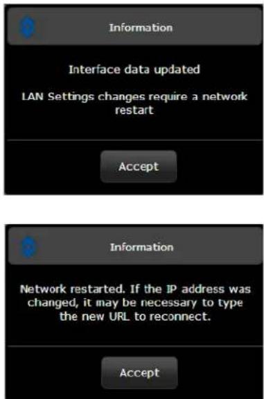
text_image
Information Interface data updated LAN Settings changes require a network restart Accept Information Network restarted. If the IP address was changed, it may be necessary to type the new URL to reconnect. Accept
text_image
Information Network restarted. If the IP address was changed, it may be necessary to type the new URL to reconnect. AcceptNote
μhe IP 'ddress is tempor'rily dispI'yed on the 'n'log video 'fter the _mer' finishes its boot _y_le. If the _mer' IP 'ddress is unknown, it is useful to reboot the _mer' 'nd w't_h for the IP Address inform'tion 'fter the _mer' boots up (usually 'bout 90 se_onds 'fter power is 'pplied).
Services Menu
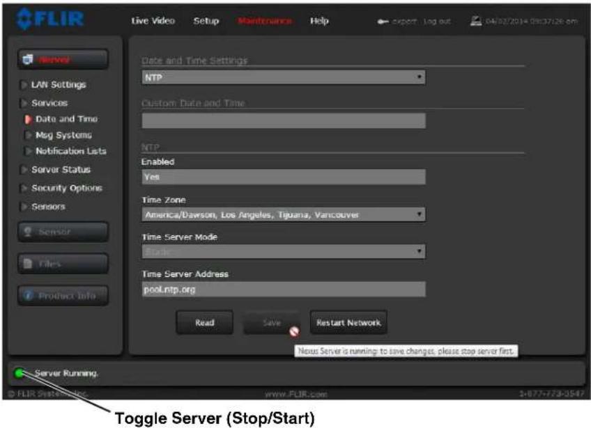
Date and Time: μhe Date and Time settings p'ge is used to _onfigure the d'te 'nd time settings3 μhe d'te, time, 'nd time zone _'n be obt'ined from 'n <μP server, or _'n be entered m'nu'lly3 If <μP mode is sele_ted, the <μP server inform'tion _'n be entered3 μhe <exus server must be stopped before _h'nges _'n be s'ved3 After s'ving _h'nges, it is ne_ess'ry to rest'rt the server to m'ke them effe_tive3
text_image
FLIR Live Video Setup Maintenance Help Date and Time Settings NTP Custom Date and Time NTP Enabled Yes Time Zone America/Dawson, Los Angeles, Tijuana, Vancouver Time Server Mode State Time Server Address pool.ntp.org Read Save Restart Network Notes Server is running to save changes, please stop server first. Server Running. FLIR Systematics www.FLIR.com 1-077-773-0547 Toggle Server (Stop/Start)
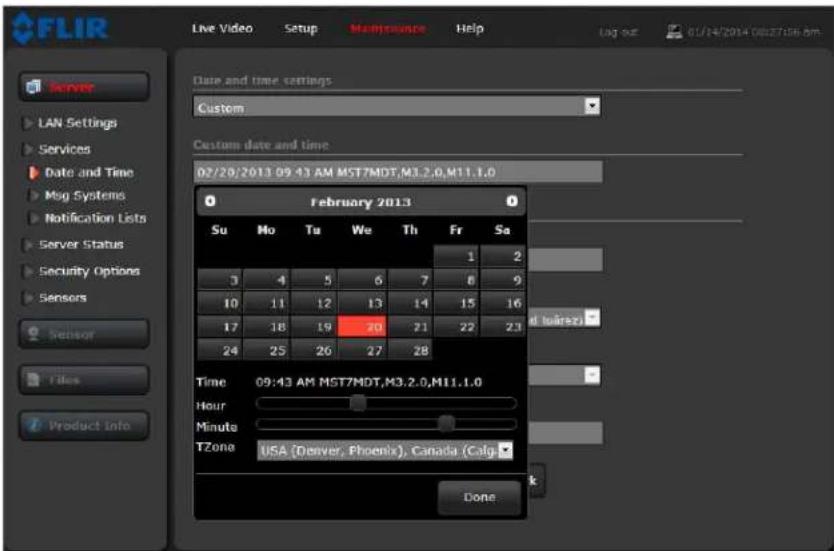
If the Custom mode is sele_ted, 'pop9up window 'llows the inform'tion to be entered m'nu'lly3
text_image
FLIR Live Video Setup Maintenance Help Log out 01/14/2014 08:27:16.8m Date and time settings Custom Custom date and time 02/28/2013 09:43 AM MST7MDT,M3.2.0,M11.1.0 February 2013 Su Mo Tu We Th Fr Sa 1 2 3 4 5 6 7 8 9 10 11 12 13 14 15 16 17 18 19 20 21 22 23 24 25 26 27 28 Time 09:43 AM MST7MDT,M3.2.0,M11.1.0 Hour Minute TZone USA (Denver, Phoenix), Canada (Calg) Doneet the d'te 'nd time p'r'meters, then sele_t the Save button 't the bottom of the p'ge3
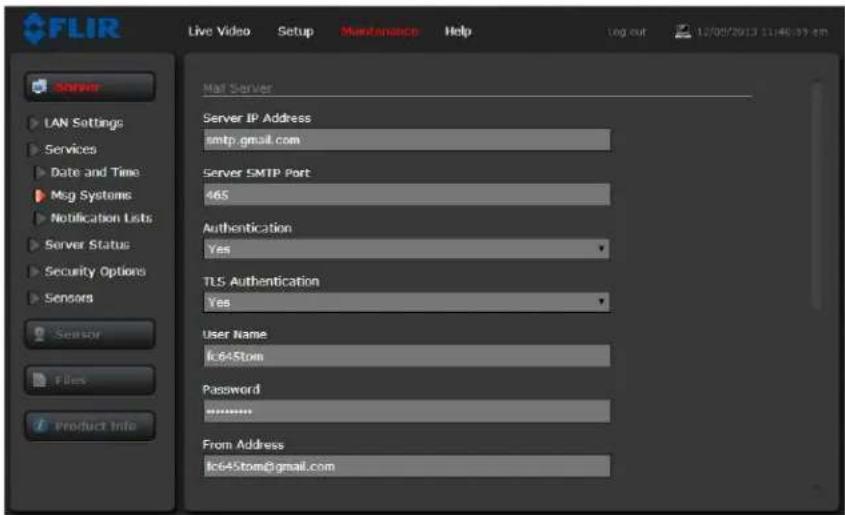
Msg Systems: =se the Msg Systems p'ge to setup ' _onne_tion to ' m'il server to send outgoing em'il notifi 'tions.
text_image
FLIR Live Video Setup Maintenance Help log out 12/08/2013 11:46:39 am Server LAN Settings Services Date and Time Msg Systems Notification Lists Server Status Security Options Sensors Sensor Files Product Info Mail Server Server IP Address smtp.gmail.com Server SMTP Port 465 Authentication Yes TLS Authentication Yes User Name lc645tom Password ****** From Address lc645tom@gmail.comIf the em'il server is on ' different network, ensure the IP def'ult g'tew'y 'nd D<> servers 're _onfigured in the LA< >ettings; refer to LA< >ettings, pg. 2-11. Configure the Msg >systems p'ge with m'il server inform'tion 'nd then _li_k Save.
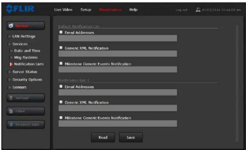
Notification Lists: =se this p'ge to setup multiple em'il 'ddresses 'nd other notifi_tions th't _'n be sent 's' result of 'l'rms being pro_essed by the Al'rm M'n'ger.
text_image
FLIR Live Video Setup Maintenance Help Log out 01/02/2014 12:44:09 am Server LAN Settings Services Date and Time Msg Systems Notification Lists Server Status Security Options Sensors Sensor Tiles Product Info Default Notification List Email Addresses Generic XML Notification Milestone Generic Events Notification Notification List 1 Email Addresses Generic XML Notification Milestone Generic Events Notification Read Saveμhe em'il 'ddress entered into the Def'ult <otifi_'tion List will be used to send ' test em'il (F< 9) from the Live xideo p'ge.
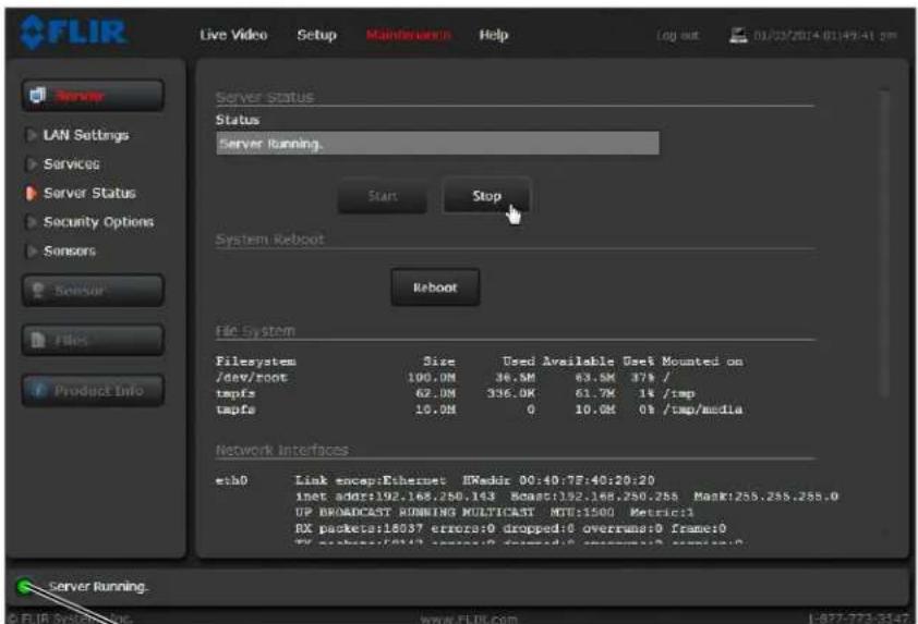
Server Status: μhe Server Status p'ge provides 'n indi_tion of the _urrent server st'tus (either running or stopped7 'nd buttons for st'rting or stopping the server or for rebooting the system3
text_image
FLIR Live Video Setup Maintenance Help Log out 01/03/2014 01:49:41 pm Server LAN Settings Services Server Status Security Options Sensors Server File Product Info Server status Status Server running. Start Stop System Reboot Reboot file System Filesystem Size Used Available Use# Mounted on /dev/root 100.0M 36.5M 63.0M 37% / tmpfs 62.0M 336.0K 61.7K 1% /tmp tmpfs 10.0M 0 10.0M 0% /tmp/media Network interfaces etb0 Link encep:Ethernet EWedir 00:40:7E:40:20:20 inet adsr:192.168.250.143 Scasr:192.168.250.255 Mask:255.255.255.0 UP BROADCAST RUNNING MULTICAST MTU:1500 Metric:1 RX packets:18037 errors:0 dropped:0 overruns:0 frame:0 RX packets:2013 errors:0 dropped:0 overruns:0 frame:0 Server Running. © FLIR System Inc. www.FLIR.com 1-877-773-3147
Toggle Server (Stop/Start)
After m'king _onfigur'tion _h'nges, it is ne_ess'ry to s've the _h'nges to the server (there is 'Save button 't the bottom of e'_h _onfigur'tion p'ge73 μhe _onfigur'tion _h'nges do not t'ke effe_t immedi'tely3 Gener'lly, it is 'Iso ne_ess'ry to stop 'nd rest'rt the server for the _h'nges to be_ome effe_tive3 μhe server h's '_onfigur'tion th't is '_tive 'nd running, 'nd 'nother _onfigur'tion th't is s'ved ('nd possibly different th'n the running _onfigur'tion73
μhe mess'ge 't the bottom of the p'ge indi_'tes the s'ved _onfigur'tion is different th'n the '_tive (running7 _onfigur'tion, 'nd it is ne_ess'ry to rest'rt the server3
You must restart the server for the changes to be effective.
It m'y t'ke up to 40 se_onds or more to stop the server, espe_i'lly when there 're multiple video stre'ms open3 Be p'tient when stopping the server3
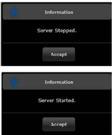
When the server is stopped 'nd the p'ge is refreshed, the st'tus will show 's ">erver >topped3" 'nd the >t'rt button will be en'bled r'ther th'n >top3
text_image
Information Server Stopped. Accept Information Server Started. AcceptCli_k on the >t'rt button to rest'rt the server, 'nd when the p'ge refreshes, the st'tus will 'g'in show 's ">server Running..."3 μhe >t'rt button will be repl'_ed by '>top button when the st'rtup pro_edure h's _ompleted3
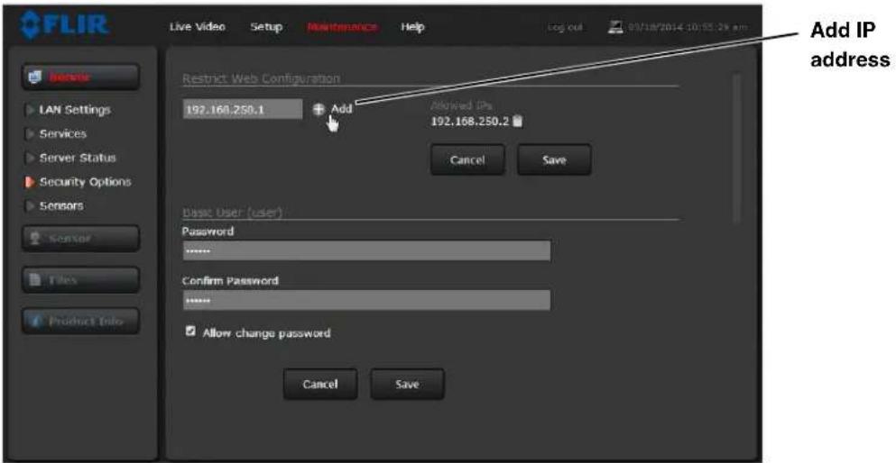
Security Options: =se the Security Options p'ge to restri_t ' ess through the _mer' web server to spe_ifi_ IP 'ddresses 'nd to set 'nd _h'nge p'sswords3 As shown below, the expert login _'n only _onfigure the user login p'ssword3
text_image
FLIR Live Video Setup Maintenance Help Log out 05/18/2014.10:55:29 am Add IP address Restrict Web Configuration 192.168.250.1 Add Allowed Dx 192.168.250.2 Cancel Save Basic User (user): Password ****** Confirm Password ****** Allow change password Cancel SaveAs 'n 'ddition'l se_urity me'sure, limit whi_h _omputers h've ' ess to the web browser interf' e3 >imply 'dd ' _omputer's IP 'ddress 'nd _li_k Add3 After 'll the 'llowed IP 'ddresses 're entered, sele_t the Save button to s've the _h'nges3
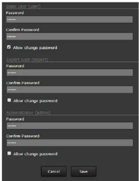
μo m'int'in se_urity of the system set new p'sswords for e'_h of the three login '__ounts (requires the admin login73
user—μhe user ' _ount _'n only use the Live Video s_reen 'nd _ontrols3
expert—μhe expert '__ount_'n use the Live Video s_reen, the_'mer' Setup s_reen, 'nd the >erver p'ges on the Maintenance s_reen3 admin—μhe 'dmin '__ount_'n use 'll s_reens3
After 'p'ssword is set 'nd_onfirmed, sele_t the Save button 't the bottom (s_roll down the p'ge, if ne_ess'ry73
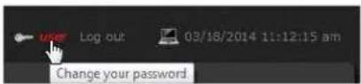
ele_ting the Allow Ch'nge P'ssword_he_k box will 'llow th't login to _h'nge their own p'ssword from 'n i_on 't the top of 'll p'ges3
text_image
Basic User (user) Password ****** Confirm Password ****** ✓ Allow change password Expert User (expert) Password ****** Confirm Password ****** ■ Allow change password Administrator (admin) Password ****** Confirm Password ****** ■ Allow change password Cancel Save2.5 Thermal Imaging Overview
μhen power is 'pplied to the FC9>eries _'mer', 'F#I] spl'sh s_reen is displ'yed for less th'n two se_onds, 'nd then the _'mer' outputs the live video im'ge3 <o oper'tor '_tion or intervention is required 'nd no _onfigur'tion of the _'mer' is ne_ess'ry3
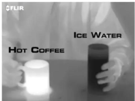
μhe therm'l _'mer' m'kes 'n im'ge b'sed on temper'ture differen_es3 In the therm'l im'ge, by def'ult the hottest item in the s_ene 'ppe'rs 's white 'nd the _oldest item is bl'_k, 'nd 'll other items 're represented 's ' gr'y s_'le v'lue between white 'nd bl'_k3

text_image
FLIR® indigo
Figure 2-3: Splash Screen
It m'y t'ke some time to get used to the therm'l im'gery from the _'mer', espe_i'lly for someone who only h's experien_e with norm'l d'ylight _'mer's3 H'ving ' b'si_ underst'nding of the differen_es between therm'l 'nd d'ylight _'mer's _'n help with getting the best perform'n_e from the therm'l _'mer'3
Both therm'l 'nd d'ylight_'mer's h've dete_tors (pixels7 th't dete_t energy3 °ne differen_e between therm'l 'nd d'ylight_'mer's h's to do with where the energy _omes from to _re'te 'n im'ge3 μhen viewing 'n im'ge with 'n ordin'ry_'mer', there h's to be some sour_e of visible light (something hot, su_h 's the sun or lights7 th't refle_ts off the obje_ts in the s_ene to the_'mer'3 μhe s'me is true with hum'n eyesight; the v'st m'jority of wh't people see is b'sed on reflected light energy3
°n the other h'nd, the therm'l_'mer' dete_ts energy th't is directly radiated from obje_ts in the s_ene3 Most obje_ts in typi_'l surroundings 're not hot enough to r'di'te visible light, but they e'sily r'di'te the type of infr'red energy th't the therm'l_'mer'_'n dete_t3 Even very _old obje_ts, like i_e 'nd snow, r'di'te this type of energy3
μhe _'mer' is _'p'ble of sensing very sm'll temper'ture differen_es, 'nd produ_es' video im'ge th't typi_'lly h's dr'm'ti _ontr'st in _omp'rison to d'ylight _'mer's3 μhis high _ontr'st level from the therm'l video en'bles intelligent video 'n'lyti_ softw're to perform more reli'bly3
text_image
FLIR HOT COFFEE ICE WATERμhe perform'n_e of the _'mer' will likely v'ry throughout the d'y3 After sunset, obje_ts w'rmed by the sun will 'ppe'r w'rmest3 E'ry in the morning, m'ny of these obje_ts will 'ppe'r _ooler th'n their surroundings, so be sure to look for subtle differen_es in the s_ene, 's opposed to just hot t'rgets3
μherm'l im'ging _'mer's 're deployed in numerous _ommer_i'l 'ppli_'tions where it is impr'_ti_'l or too expensive to use '_tive illumin'tion (lights73 μhey 're perfe_t for ' wide v'riety of 'ppli_'tions in_luding tr'nsport'tion, m'ritime, se_urity, fire fighting, 'nd medi_'l 'ppli_'tions3 μhe _'mer's often provide improved d'ytime viewing in environments where tr'dition'l video _'mer' perform'n_e suffers, su_h 's in sh'dows or b'_klit s_enes3
μhe FC9>eries _'mer' is 'st'te9of9the9'rt therm'l im'ging system th't will provide ex_ellent night visibility 'nd situ'tion'l 'w'reness, without 'ny form of n'tur'l or 'rtifi_i'l illumin'tion3 μhe system is e'sy to use, but it is useful to underst'nd how to interpret wh't is disp'yed on the monitor3
While the im'gery on the monitor m'y 't first look simil'r to ordin'ry bl'_k 'nd white d'ylight video, experien_e with the _'mer' in v'rying _onditions 'nd se'sons will le'd to 'n 'ppre_i'tion of the _h'r'_teristi_s th't m'ke therm'l im'ging distin_t. A few tips on how to interpret the im'ges m'y be helpful.
μhe therm'l_'mer' does not sense light like _onvention'l_'mer's; it senses he't or temper'ture differen_es. μhe_'mer' senses sm'll "differen_es" in 'pp'rent r'di'tion from the obje_ts in view, 'nd displ'ys them 's either white (or lighter sh'des of gr'y7 for w'rmer obje_ts, 'nd bl'_k (or d'rker sh'des of gr'y7 for _older obje_ts.
μhe therm'l im'ging_'mer' relies on the f'_t th't 'll obje_ts, even very _old obje_ts like i_e, emit therm'l energy in the portion of the infr'red spe_trum th't this_'mer'_'n "see", the long w've infr'red (LWIR7. μherefore, unlike 'n illumin'ted infr'red_'mer', 'therm'l_'mer' does not need 'n 'dition'l '_tive illumin'tion sour_e, 'nd _re'tes video b'sed on dire_tly r'di'ted r'ther th'n refle_ted energy.
μhis is why hot obje_ts su_h 's p'rts on 'n engines 'nd exh'ust pipes 'ppe'r white, while the sky, puddles of w'ter 'nd other _old obje_ts 'ppe'r d'rk (or _ool7 4. >_enes with f'mili'r obje_ts will be e'sy to interpret with some experien_e. μhe_'mer' 'utom'ti_'lly optimizes the im'ge to provide the best _ontr'st in most _onditions, 'nd in some_'ses the >_ene Presets mentioned 'bove 'nd other settings_'n be used to further improve the im'ge.
With the R'diometry fe'ture, the FC9>eries R_'mer' _'n provide temper'ture me'surements 'nd gener'te 'l'rms b'sed on temper'tures th't _ross pre9defined levels. μhe 'bility to use ' therm'l _'mer' to m'ke re'son'bly '_ur'te temper'ture me'surements requires 't le'st ' minimum level of expertise in the s_ien_e known 's thermogr'phy. μhere 're quite ' few f'_tors th't will influen_e the '_ur'_y 'nd pre_ision of ' temper'ture me'surement from the '_mer', 'nd users 're en_our'ged to seek tr'ining. μhe Infr'red μr'ining _enter offers tr'ining (in_luding online tr'ining7 'nd _ertifi_'tion in 'll 'spe_ts of thermogr'phy: http://www.infr'reddtr'ining_om/.
2.6 Troubleshooting Tips
If help is needed during the inst'll'tion pro_ess, _ont'_t the lo_'l FLIR represent'tive, send 'n em'il to ns.support@flir._om, or_'ll 888974793+47 inside the =>. μhe FLIR >ensors M'n'ger softw're_'n be downlo'ded from http://support.flir._om/. 'nd is ' good tool to h've inst'llled for troubleshooting purposes. FLIR >systems, In_. offers '_omprehensive sele_tion of tr'ining _ourses to help get the best perform'n_e 'nd v'lue from the therm'l im'ging_'mer'. Find out more 't the FLIR tr'ining web p'ge: http://www.flir._om/tr'ining._
Image freezes momentarily
By design, the _'mer' im'ge will freeze moment'rily on ' periodi_ b'sis during the Fl't Field Corre_tion (FFC) _y_le ('Iso known 's <on9=niformity Corre_tion or <=C). Every few minutes, the im'ge will moment'rily freeze for ' fr'_tion of ' se_ond while the _'mer' performs ' fl't field_orre_tion. A shutter '_tiv'tes inside the _'mer' 'nd provides ' t'rget of uniform temper'ture,' 'llowing the _'mer' to _orre_t for 'mbient temper'ture _h'nges 'nd provide the best possible im'ge. Just prior to the FFC,' sm'll green squ're will 'ppe'r in the _orner of the s_reen.
=sing F>M, it is possible to 'djust the frequen_y of how often the FFC operation o_urs. =sing the Adv'n_ed >ensor Control, it is possible to _h'nge the FFC interv'l or to disable the 'utom'ti_FFC entirely by setting it to M'nu'l mode. For the best possible image, it is re_ommended the f'_tory settings 're used.
No video
If the 'mer' will not produ_e 'n im'ge, _he_k the video _onne_tion 't the 'mer' 'nd 't the disp'l'y. If the _onne_tors 'ppe'r to be properly _onne_ted but the 'mer' still does not produ_e 'n im'ge, ensure th't power h's been properly 'pplied to the 'mer' 'nd the _ir_uit bre'ker is set properly. If ' fuse w's used, be sure the fuse is not blown. If the video 'bling is suspe_ted 's ' possible sour_e of the problem, plug ' monitor into the RCA _onne_tion inside the 'mer' 'nd determine if it produ_es 'n im'ge.
When the _mer' is powered on, it will do <=C operation shortly 'fter st'rtup. If it is un_ert'in if the _mer' is re_eiving power, it m'y be useful to listen to the _mer' to he'r if the _li_k9_li_k of the shutter me_h'nism _n be he'rd. It m'y only be possible to perform this test when the _mer' is on 'work ben_h r'ther th'n in its inst'lled position.
If the _mer' still does not produce 'n im'ge, _ont'_t the FLIR de'ler or reseller who provided the _mer', or _ont'_t FLIR dire_tly (_ont'_t inform'tion is provided on the re'r_over of this m'nu'l).
Performance varies with time of day
μhere m'y be differen_es in the w'y the_'mer' performs 't different times of the d'y, due to the diurn'l _y_le of the sun. Re_'ll th't the_'mer' produ_es 'n im'ge b'sed on temper'ture differen_es.
At _ert'in times of the d'y, su_h 's just before d'wn, the obje_ts in the im'ge s_ene m'y 'll be roughly the s'me temper'ture, _omp'red to other times of the d'y. Comp're this to im'gery right 'fter sunset, when obje_ts in the im'ge m'y be r'di'ting he't energy th't h's been 'bsorbed during the d'y due to sol'r lo'ding. Gre'ter temper'ture differen_es in the s_ene gener'lly will 'llow the _mer' to produ_e high9_ontr'st im'gery.
Perform'n_e m'y 'Iso be 'ffe_ted when obje_ts in the s_ene 're wet r'ther th'n dry, su_h 's on ' foggy d'y or in the e'ry morning when everything m'y be _o'ted with dew. =nder these _onditions, it
m'y be diffi_ult for the _'mer' to show the temper'ture the obje_t itself, r'ther th'n of the w'ter _o'ting.
Unable To Communicate Over >thernet
First _he_k to ensure the physi_'l _onne_tions 're int'_t 'nd th't the _'mer' is powered on 'nd providing 'n'log video to the monitor. When the _'mer' is turned on, _onfirm the st'rtup inform'tion is displayed on the 'n'log monitor 'fter 'pproxim'tely 2 min. For example:
S/N: 1234567
IP Addr: 192.168.250.116
Confirm th't the IP 'ddress for the PC (for ex'mple, 192.168.2+0.1) is on the s'me network 's the _mer'.
the
text_image
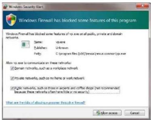
Windows Firewall has blocked some features of this program Windows Firewall has blocked some features of vp.exe on all public, private and domain networks. Name: vp.exe Publisher: Unknown Patty: C:\program files (.x86)\nexus\nexus common\vp.exe Allow vp.exe to communicate on these networks: Domain networks, such as a workplace network Private networks, such as my home or work network Public networks, such as those in airports and coffee shops (not recommended because these networks often here little or no security) What are the risks of allowing a program through a firewall? Allow access CancelBy default the 'mer' will bro'd_st "dis_overy" p'_ket two times per se_ond. When F>M st'rts up, it listens to the network for the dis_overy p'_kets. If no 'mer's 're listed in the Dis_overed >ervers list, press the Refresh button. If the list is still empty, it indi_tes no dis_overy p'_kets were re_eived. μhis _ould be due to ' wide v'riety of limitations with the network, the PC, or the _mer'.
If ne_ess'ry, use 'p'_ket sniffer utility su_h 's Wiresh'rk to _'pture p'_kets 'nd _onfirm the p'_kets 're being re_eived by the PC from the_'mer'.
Unable to control the camera
If the _'mer' does not respond to _omm'nds (for example, the _'mer' does not zoom when the zoom in button is _li_ked), the user m'y not h've _ontrol of the _'mer'. μhe Web server 'llows two sessions to be _onne_ted to the _'mer' 't' time. By default, _ontrol of the _'mer' will 'utom'ti_'lly be requested.
In F>M, if there 're multiple_'mer's 'nd/or multiple F>M _lients, it m'y be ne_ess'ry to m'nu'lly m'ke the_'mer' '_tive 'nd t'ke _ontrol of it.
In the >ensors P'nel, if the_'mer' is the_'tive sensor, there will be 'n "(A_tive7" notifi_'tion next to the n'me of the_'mer'3 °only one_'mer' or sensor_'n be '_tive 't ' time3 μo m'ke the_'mer' '_tive, right _li_k on the i_on to the left of the_'mer' n'me 'nd sele_t ">et A_tive", or simply double9_li_k on the i_on3
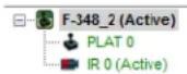
μhe i_on to the left of the_'mer' n'me indi_'tes the st'tus of the sensor3 μhe following is 'list of the possible i_ons 'nd the me'ning of e'_h one3

Conne_ted 'nd Controlled
μhis i_on indi_tes the _mer' h's been dis_overed 'nd 'dded to the list of '_tive servers, 'nd the _mer' is '_tively " _onne_ted" to the F>M _lient 'nd re_eiving st'tus upd'tes3 μhe joysti_k in the i_on indi_tes the user h's _ontrol of the _mer'3 μo rele'se _ontrol of the _mer', right _li_k on the i_on 'nd sele_t "]ele'se Control"3

Dis_overed
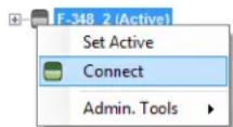
μhis i_on indi'tes the 'mer' h's been dis_overed 'nd 'dded to the list of 'tive servers, but the 'mer' is not 'tively "onne_ted" to F>M, 'nd therefore F>M is not re_eiving st'tus upd'tes3 μo_onne_t to the 'mer', right _li_k on the i_on 'nd sele_t "Conne_t"3 Altern'tively, it is possible to double9 _li_k the i_on to _onne_t3

Conne_ted
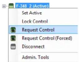
μhis i_on indi_'tes the_'mer' h's been dis_overed 'nd 'dded to the list of '_tive servers, 'nd the_'mer' is '_tively " _onne_ted" to F>M 'nd re_eiving st'tus upd'tes3 μo t'ke _ontrol of the_'mer', right _li_k on the i_on 'nd sele_t "]equest Control"3 Altern'tively, it is possible to double9_li_k the i_on to t'ke _ontrol3
text_image
F-348 2 (Active) Set Active Lock Control Request Control Request Control (Forced) Disconnect Admin. Tools
<ot Conne_ted
μhis i_on indi'tes the 'mer' h's been dis_overed 'nd 'dded to the list of 'tive servers, 'nd F>M is trying to _onne_t to the 'mer', but some kind of problem is preventing F>M from re_eiving st'tus upd'tes the 'mer'3 μhis _ould be do to ' wide v'riety of problems in the 'mer', network or PC3 Most often this situ'tion o_urs when ' firew'll 'llows _ert'in p'_kets (su_h 's the dis_overy p'_kets7 but not others (the p'_kets needed for " _onne_tion"73
General >rrors

In the st'tus b'r 't the bottom of the F>M s_reen there m'y be 'n indi_'tion th't 'n error h's o_urred. When the _ursor is moved over the error i_on (ex_l'm'tion m'rk), the error will be dispI'yed in 'tempor'ry pop-up. It is possible to view 'll the error mess'ges by sele_ting the μools t'b 't the top of he s_reen, 'nd then sele_t the Log button to the left.
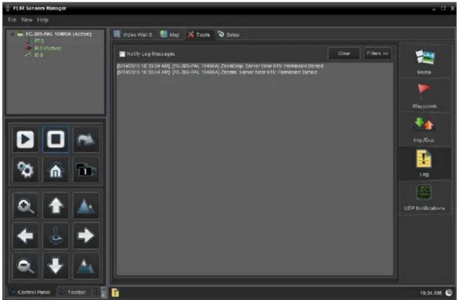
text_image
FLIR Sensors Manager File View Help FC-305-PAL 10486A (Active) FT 0 B1.0 (Active) ID 0 Video Wall 0 Map Tools Setup Notify Log Messages [07/14/2015 10:33:04 AM] [FC-305-PAL 10486A] Zonacstop, Server Error BTS; Permission Denied. [07/14/2015 10:33:04 AM] [FC-305-PAL 10486A] Zoomn, Server Error BTS; Permission Denied. Clear Filters >> Media Waypoints Imp/Exp Log UDP Notifications Control Panel Toolbar 19:34 AMUnable to View Video Stream
If the video stre'm from the_'mer' is not disple'yed in F>M, it _ould be th't the p'_kets 're blo_ked by the firew'll, or there _ould be '_onfli_t with video _ode_s th't 're inst'lled for other video progr'ms.
When disp'ying video with F>M for the first time, the Windows Person'l Firew'll m'y 'sk for permission to 'llow the FLIR xideo Pl'yer (vp.exe) to _ommuni_'te on the network. >ele_t the _he_k boxes (dom'in/priv'te/publi_) th't 're 'ppropri'te for the network.
If ne_ess'ry, test to m'ke sure the video from the_'mer' _'n be viewed by 'generi_ video pl'yer su_h 's xLC medi' pl'yer (http://www.videol'n.org/vl_)/.μo view the video stre'm, spe_ify Rμ>P port ++4 'nd the 'ppropri'te stre'm n'me su_h 's "_h0". For ex'mple:
rtsp://192.168.2+0.116:++4/_h0
Refer to xideo, pg. 3-18 for 'ddition'l inform'tion on RμP 'nd stre'm n'mes.
Noisy image
With the 'n'log video sign'l, ' noisy im'ge is usu'lly 'ttributed to ' _'ble problem (too long or inferior qu'lity) or the _'ble is pi_king up ele_trom'gneti_interferen_e (EMI) from 'nother devi_e. Although _o'x _'ble h's built-in losses, the longer the _'ble is (or the sm'ller the wire g'uge/thi_kness), the more severe the losses be_ome; 'nd the higher the sign'l frequen_y, the more
pronoun_ed the losses. =nfortun'tely this is one of the most _ommon 'nd unne_ess'ry problems th't pl'gues video systems in gener'l.
C'ble _h'r'_teristi_s 're determined by ' number of f'_tors (_ore m'teri'l, diele_tri_m'teri'l 'nd shield _onstru_tion, 'mong others7 'nd must be _'refully m't_hed to the spe_ifi_'ppli_tion. Moreover, the tr'nsmission _h'r'_teristi_s of the _'ble will be influen_ed by the physi_l environment through whi_h the _'ble is run 'nd the method of inst'll'tion. =se only high qu'lity _'ble 'nd ensure the _'ble is suit'ble to the m'rine environment.
Che_k _'ble _onne_tor termin'tions. Inferior qu'lity _onne_tions m'y use multiple 'd'pters whi_h _'n _'use un'__ept'ble noise. =se ' high9qu'lity video distribution 'mplifier when splitting the sign'l to multiple monitors.
Image too dark or too light
By def'ult the FC9>eries _'mer' uses 'n Autom'ti_ G'in Control (AGC7 setting th't h's proven to be superior for most 'ppli_'tions, 'nd the _'mer' will respond to v'rying _onditions 'utom'ti_'lly. μhe inst'ller should keep in mind th't the sky is quite _old 'nd _'n strongly 'ffe_t the over'll im'ge. It m'y be possible to 'void ' problem by slightly moving the _'mer' up or down to in_lude (or ex_lude7 items with hot or _old temper'tures th't influen_e the over'll im'ge. For ex'mple, ' very _old b'_kground (su_h 's the sky7 _ould _'use the _'mer' to use ' wider temper'ture r'nge th'n 'ppropri'te.
μhere 're five >_ene Presets th't use ' _ombin'tion of settings to produ_e different _onfigur'tions th't _ould improve the video im'ge for ' given set of _onditions. μhe presets _'n be toggled with the >_ene Presets button on the Live Video p'ge.
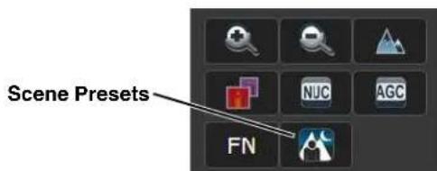
text_image
Scene Presets FNμhe presets _'n 'Iso be sele_ted from the >_ene Presets in the Setup p'ge. Refer to μherm'l lm'ge _>etup, pg. 394
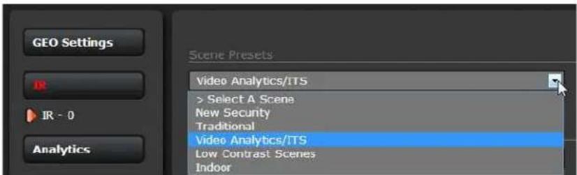
text_image
GEO Settings IR IR - 0 Analytics Scene Presets Video Analytics/ITS > Select A Scene New Security Traditional Video Analytics/ITS Low Contrast Scenes IndoorAvailable Scene Presets
>astern or Western >xposure
°n_e inst'illed, the_'mer' m'y point dire_tly e'st or west, 'nd this m'y_'use the sun to be in the field of view during _ert'in portions of the d'y. We do not re_ommend intention'lly viewing the sun, but looking 't the sun will not perm'nently d'm'ge the sensor. In f'_t the therm'l im'ging_'mer' often provides '_onsider'ble 'dv'nt'ge over '_onvention'l_'mer' in this type of b'_k9lit situ'tion.
However, the sun m'y introdu_e im'ge 'rtif'_ts th't will eventu'lly_orre_t out. 'nd it m'y t'ke some time for the_'mer' to re_over. μhe 'mount of time needed for re_overy will depend on how long the_'mer' w's exposed to the sun. μhe longer the exposure, the longer the re_overy time needed.
natural_image
Sunset over a road with visible sun flare and silhouetted buildings (no text or symbols)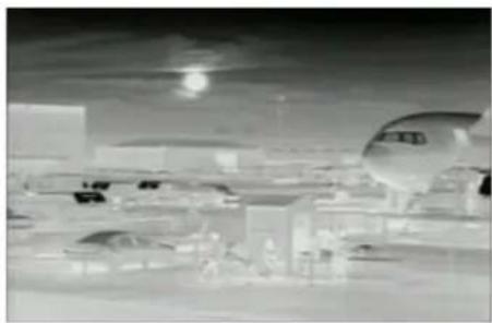
natural_image
Black-and-white cityscape with modern buildings and a large car under a moonlight (no visible text or symbols)Figure 2-4: Images facing sun from standard camera (left) and thermal camera (right)
2.7 Setting the IP address on a Windows PC
o set the _omputer IP 'ddress in Windows, first _onne_t the PC to 'swit_h, or _onne_t it to the _'mer' 'nd ensure the _'mer' h's power.
tep 8 With the PC or l'ptop _onne_ted to the swit_h (or if b'_k9to9b'_k with the _mer', with the _mer' powered on), open the Control P'nel,
h'ring Center (' Windows 7 ex'mple is shown). μhe _onne_tion to the _mer' should show in the A_tive <etworks.
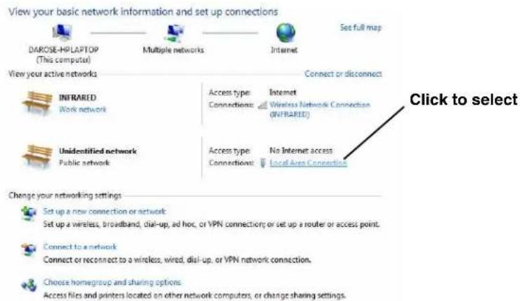
text_image
View your basic network information and set up connections DIAROSE-HPLAPTOP (M this computer) Multiple networks Internet Set full map View your active networks Connect or disconnect INFRARED Work network Access type: Internet Connections: Wireless Network Connection (INFRARED) Unidentified network Public network Access type: No Internet access Connections: Local Area Connection Change your networking settings Set up a new connection or network Set up a wireless, broadband, dial-up, ad hoc, or VPN connection; or set up a router or access point. Connect to a network Connect or reconnect to a wireless, wired, dial-up, or VPN network connection. Choose homegroup and sharing options Access files and printers located on other network computers, or change sharing settings. Click to select
tep 2 Cli_k to sele_t the Lo_'I Region Conne_tion then _li_k Properties, 's shown 't the right.
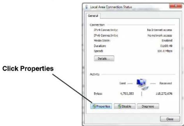
text_image
Local Area Connection Status General Connection IPv4 Connectivity: No Internet access IPv6 Connectivity: No network access Media State: Enabled Durations 0.108.49 Speeds 100.0 Mb/s Details... Click Properties Activity Sent ——— Received Bytes: 4,793,353 | 115,272,676 Properties Disable Diagnose Closetep 3 >ele_t Internet Proto_ol xersion 4 (μCP/IPv4) 's shown. μhen_li_k Properties.
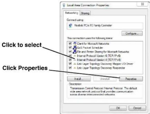
text_image
Local Area Connection Properties Networking Sharing Connect using: Rostok PCIe FE Family Controller Configure... This connection uses the following items: Client for Microsoft Networks Gas'S Packet Scheduler File and Fenter Sharing for Microsoft Networks - Internet Protocol Version 6 (TCP/IPv6) - Internet Protocol Version 4 (TCP/IPv4) - Link Layer Topology Discovery Mapper U/O Driver - Link Layer Topology Discovery Responder Install... Uninstall Properties Description Transmission Control Protocol/Internet Protocol: This default wide area network protocol that provides communication across diverse interconnected networks. OK Cancel Click to select Click Propertiestep 4 >ele_t Use the following IP address, then enter 192.168.2+0.xxx, where xxx is 'ny number between 1-2++, other th'n 116 (the_'mer' default).
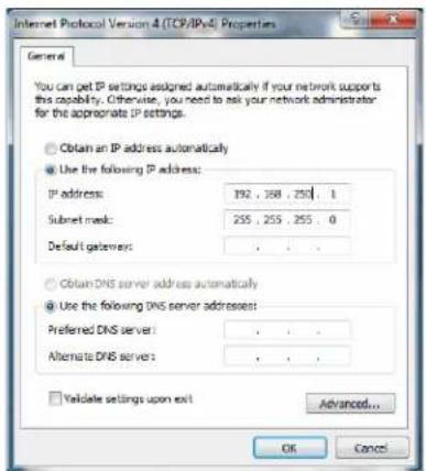
text_image
Internet Protocol Version 4 (TCP/IPv4) Properties General You can get IP settings assigned automatically if your network supports the capability. Otherwise, you need to ask your network administrator for the appropriate IP settings. ○ Obtain an IP address automatically ● Use the following IP address: IP address: 192 . 388 . 250 . 1 Subset mask: 255 . 255 . 255 . 0 Default gateway: . ○ Obtain DNS server address automatically ● Use the following DNS server addresses: Preferred DNS server: . Alternate DNS server: . □ Validate settings upon exit Advanced... OK Canceltep + >et the >ubnet m'sk to 2++.2++.2++.0, then _li_k °K.
3 Advanced Configuration
In this _h'pter, 'ddition'l setup 'nd _onfigur'tion settings rel'ted to the following topi_s 're des_ribed:
•°ptimizing the therm'l im'ge
- >etting up dete_tion 're's for xideo An'lyti_s (xA7
- >etting up me'surement spots 'nd 're's for temper'ture monitoring
- Configuring 'I'm responses 'nd em'il notifi_tions
- Configuring the _mer' to work with 'third9p'rty ×M> (°
- >etting up the video stre'ms to optimize qu'lity 'nd network perform'n_e
When _onfigur'tion _h'nges 're m'de with the web browser, the settings 're s'ved to '_onfigur'tion file. It is 'good ide' to m'ke 'b'_kup of the existing _onfigur'tion file prior to m'king _h'nges, 'nd 'nother b'_kup on_e the _h'nges 're fin'lized. If ne_ess'ry the '_mer' _'n be restored to its origin'l f'_tory _onfigur'tion or one of the s'ved _onfigur'tions (refer to Files Menu, pg. 39267.
3.1 Setup Menu
μhe Setup menu h's _onfigur'tion options for:
- setting the GE° p'r'meters (geo9referen_e m'p lo_tion used by progr'ms like F>M7
• m'king _h'nges to the IR (therm'I7_'mer' - defining xideo An'lyti_s motion detet_ tion zones
- setting R'diometry temper'ture me'surement 're's (FC9>eries R only7
It is ne_ess'ry to h've _ontrol of the _mer' to m'ke >etup _h'nges. μhe _h'nges m'de through the Setup menu h've 'n immedi'te effe_t (it is not ne_ess'ry to stop 'nd rest'rt the server7.
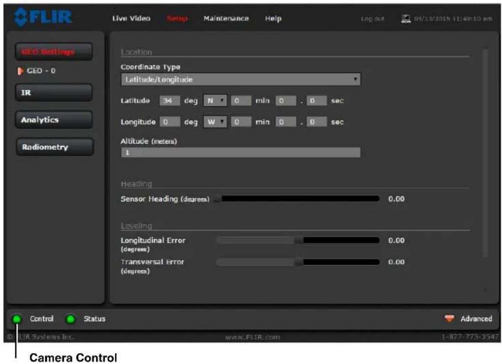
text_image
FLIR Live Video Setup Maintenance Help Log out 05/13/2015 11:49:10 am GEO Settings GEO - 0 IR Analytics Radiometry Location Coordinate Type Latitude/Longitude Latitude 34 deg N 0 min 0 . 0 sec Longitude 0 deg W 0 min 0 . 0 sec Altitude (meters) 1 Heading Sensor Heading (degrees) 0.00 Leveling Longitudinal Error (degrees) 0.00 Transversal Error (degrees) 0.00 Control Status Advanced FLIR Systems Inc. www.FLIR.com 1-877-773-3547 Camera Control3.1.1 Thermal Image Setup
In most inst'll'tions it will not be ne_ess'ry to _h'nge the therm'l _mer' from the def'ult settings3 However in some situ'tions, depending on we'ther, time of d'y 'nd so on, it m'y be useful to m'ke _h'nges to the video im'ge to enh'n_e the im'ge by modifying one or more of the p'r'meters3 In most situ'tions, it will be 'dequ'te to sele_t ' different AGC >_ene Preset (des_ribed below73 However, be 'w're th't when the _onditions _h'nge the _mer' m'y need to be 'djusted 'g'in; for th't re'son it is ' good ide' to know how to restore the f'_tory def'ult settings 's well3
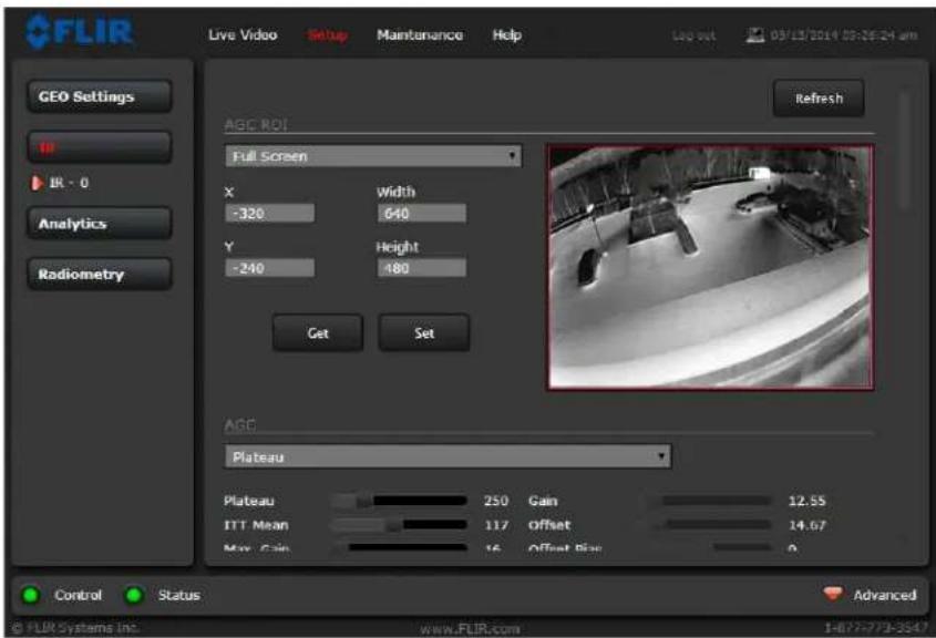
text_image
FLIR Live Video Setup Maintenance Help GEO Settings REFRESH AGC ROI Full Screen X Width -320 640 Y Height -240 480 Get Set AGC Plateau Plateau 250 Gain 12.55 ITT Mean 117 Offset 14.07 Max Gain 16 Offset Size 0 Control Status Advanced © FLIR Systems Inc. www.FLIR.com 14877-779-3547IR page
In the IR p'ge, 'single JPEG im'ge ('sn'pshot7 is displ'yed in the upper right9h'nd_orner3 μo upd'te this im'ge 't'ny time, sele_t the Refresh button in the upper right3 μhis will _'use the entire p'ge to refresh, in_luding the im'ge 'nd'll the p'r'meter v'lues (be p'tient, this m'y t'ke some time73
μo m'ke 'djustments to the therm'l im'ge, it is possible to modify the Autom'ti_G'in Control (AGC7 settings, whi_h 're grouped under the AGC ROI, AGC, 'nd Scene Presets he'dings3 In 'ddition, the det'il in the im'ge _'n be emph'sized with the Digital Detail >nhancement (DD>) settings3μhe over'll im'ge disp'l'y ('Iso known 's Pol'rity or Color P'lette7 is determined by the #ook =p μ'ble (#=μ7 sele_ted in the Misc. (Lookup Table) se_tion3
AGC ROI: μhe AGC ]egion °f Interest ( )°17 determines wh't portions of the im'ge 're used in the _'l_ul'tion of the AGC3 By default 'll of the pixels in the im'ge 're _onsidered (Full >_reen7; in some _'ses it m'y be possible to improve the _ontr'st if ' portion of the im'ge is ex_luded3
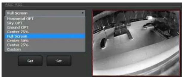
text_image
ACC ROI Full Screen Horizontal OPT Sky OPT Ground OPT Center 75% Full Screen Center 50% Center 25% Custom Get SetAGC: μhe AGC p'r'meters _ontrol the over'll brightness 'nd _ontr'st 'nd determine how the over'll video im'ge 'ppe'rs3 μhe def'ult PI'te'u 'lgorithm is suit'ble for most inst'll'tions, but in some_'ses one of the other sele_tions m'y
provide ' more 'ppe'ling im'ge, depending on person'l preferen_es. Be 'w're the settings th't 're optim'l 't one time m'y be less optim'l ' short time l'ter, sin_e _onditions su_h 's we'ther 'nd time of d'y 'ffe_t the im'ge 'nd 're _onst'ntly _h'nging.
Experiment with different AGC modes to find the settings th't work best for the p'rti_ul'r inst'll'ttion (it m'y be best to st'rt with the >_ene Presets options, see below). It is 'lw'ys possible to restore the def'ult settings by sele_ting the Factory Defaults button 't the bottom of the p'ge.
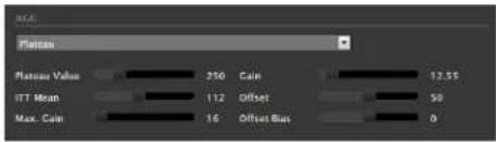
text_image
AAG Floor Value 250 Gain 12.55 ITT Mean 112 Offset 50 Max. Gain 16 Offset Max 0With the Pl'te'u mode, the lμμ Me'n p'r'meter effe_ts over'll brightness, 'nd M'x G'in _'n gener'lly be used to in_re'se _ontr'st ('lthough it m'y 'Iso in_re'se noise due to g'in).
Scene Presets: E'_h >_ene Preset provides ' _ombin'tion of AGC 'nd DDE p'r'meters th't m'y be preferred for _ert'in types of _onditions. >ele_t' preset th't provides 'n im'ge th't is optim'l for the inst'll'tion. Re 'll the >_ene preset _'n 'lso be toggled by sele_ting the μoggle >_ene Preset button from the Live Video p'ge _ontrol p'nel.
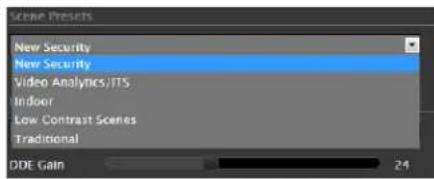
text_image
Scene Presets New Security New Security Video Analytics/ITS Indoor Low Contrast Scenes Traditional DDE Gain 24Digital Detail >nhancement (DD>): DDE is 'n im'ge pro_essing te_hnique th't enh'n_es det'ils by emph'sizing lines 'nd edges.
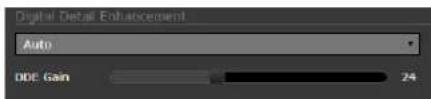
text_image
Digital Detail Enhancement Auto ODE Gain 24Flat Field Correction (FFC): μhe FFC oper'tion _'n_orre_t for non9uniform responsiveness within the pixel 'rr'y. A shutter '_tiv'tes inside the _'mer' 'nd provides ' t'rget of uniform temper'ture, 'llowing the _'mer' to _orre_t for 'mbient temper'ture _h'nges 'nd provide the best possible im'ge. μhe _'mer' performs FFC 't regul'r interv'ls or when the 'mbient temper'ture _h'nges, but _'n 'Iso be performed 's desired 'nd m'y _'use 'n over'll im'ge improvement. Refer to lm'ge freezes moment'rily, pg. 2918.
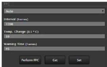
text_image
FFC Auto Interval (frames) 7200 Temp. Change (0.1 * C) 10 Warning Time (frames) 45 Perform FFC Get SetMisc. (Lookup Table): E'_h Look =p μ'ble (L=μ) provides 'different disp'l y of the v'rious dete_ted levels of therm'l energy 's either _olors or gr'y9s_'le v'lues. Look =p μ'ble 1 is white hot 'nd Look =p μ'ble 2 is bl'_k hot; the other t'bles 'ssign different _olors to different temper'tures. μthese _olor p'lettes _n 'Iso be sele_ted from the Live xideo p'ge (refer to μoggle P'lette, pg. 296).
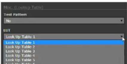
text_image
Misc. (Lookup Table) Test Pattern No LUT Look Up Table 1 Look Up Table 1 Look Up Table 2 Look Up Table 3 Look Up Table 4 Look Up Table 5 Look Up Table 6Save Settings
Cli_k the Save Settings button 't the bottom of the p'ge to store the _urrent settings 's power up defaults. μo restore the origin'l settings, sele_t the Factory Defaults button 'nd then _li_k on Save Settings.
text_image
Save Settings Factory Defaults Reboot3.1.2 Video Analytics Setup
μhe An'lyti_s fun_tion of the FC9>eries _'mer' provides the _'p'bility to dete_t motion 'nd _h'r'_terize dete_ted obje_ts 's hum'n or vehi_le b'sed on size 'nd 'spe_t r'tio (height 'nd width). =sing the Setup menu An'lyti_s p'ge (or the Adv'n_ed >ensors Control in F>M), up to four motion dete_tion 're's _'n be _re'ted with independent dete_tion settings. When en'bled, these dete_tion 're's provide 'l'rm sign'ls to the _'mer' softw're, 'nd the _'mer' _'n t'ke 'n '_tion lo_Illy (su_h 's t'king ' sn'pshot or sending 'n em'il) or _'n send the 'l'rm over the network to other systems or devi_es. =se the Maintenance menu (requires the 'dmin login), to define the '_tions resulting from e'_h 'l'rm _ondition (Al'rm M'n'ger, pg. 3923).
Analytics page
μo use xideo An'lyti_s first it is ne ess'ry to set up 're's (or regions) for dete_tion. In some situ'tions it m'y 'Iso be useful to use multiple dete_tion regions (up to four) to in_lude (or ex_lude) different 're's in the s_ene 'nd to set 're'9spe_ifi_dete_tion p'r'meters. μhe An'lyti_s p'ge 'llows the user to 'dd 're's with four or eight _orners. E'_h 're' is 'ssigned 'n Al'rm ID number (0 to 3) b'sed on the order in whi_h it is _re'ted 'nd the 'v'il'ble IDs. If 'n 're' is deleted, its Al'rm Id will be 'v'il'ble for reuse.
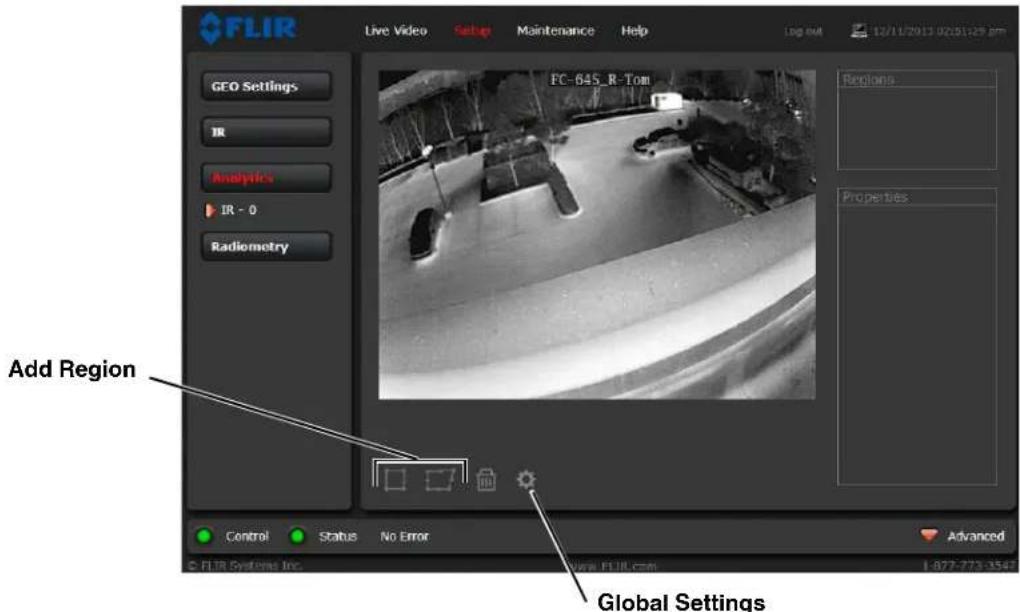
text_image
FLIR Live Video Setup Maintenance Help Log 4M 12/11/2013 02:51:29 pm GEO Settings IR Analytics IR - 0 Radiometry FC-645_R-Tom Regions Properties Add Region Control Status No Error Advanced © FLIR Systems Inc. www.FLIR.com 1.877-773-3547Cli_k the ge'r i_on below the im'ge to '__ess the Glob'l >ettings. μhe pop9up window provides the 'bility to en'ble or dis'ble 'n'lyti_s 'nd set the dete_tion sensitivity.
μhere 're five settings for sensitivity: 0 9 low, 2+ 9 mid low, +0 9 mid, 7+ 9 mid high, 'nd 800 9 high. >ensitivity is set to whi_hever of these five options is _losest. For ex'mple, 30 would go to 2+ 9 mid low. With lower sensitivity, sm'ller (dist'nt) obje_ts 're not dete_ted. μo en'ble the An'lyti_s fe'ture, set An'lyti_s En'bled to Yes, _li_k Save, 'nd then _li_k the ge'r i_on to return to the An'lyti_s >etup p'ge.
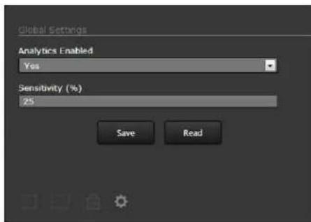
text_image
Global Settings Analytics Enabled Yes Sensitivity (%) 25 Save ReadCreating Motion Detection Areas: μo _re'te 'dete_tion 're', sele_t one of the polygon i_ons (4 or 8 verti_es¹) 'nd ' new 're' will 'ppe'r on the im'ge. Dr'g 'ny of the highlighted _ir_les in the polygon to exp'nd 'nd define the dete_tion 're'. μhen _onfigure the p'r'meters in the Properties box to set the 're'9spe_ifi_dete_tion p'r'meters (des_ribed in the following se_tions). >et A_tive to Yes or <o to turn on or off dete_tion in the sele_ted 're'. When _onfiguring 'nd testing the hum'n 'nd vehi_le settings, tempor'rily set the Dete_tion Box p'r'meter to Yes to disp'l'y different _olor bounding boxes on the im'ge th't indi_'te the st'tus of the 'n'lyti_s (the Save button 't the bottom h's to be _li_ked before 'ny boxes 're shown).
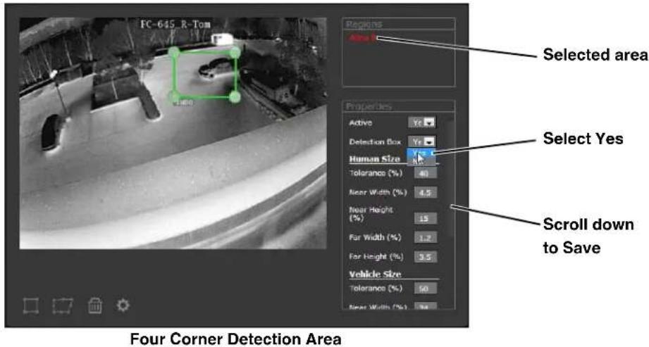
text_image
FC-645 R-Tom Selected area Properties Active Yes Detection Box Yes Human Size Tolerance (%) 40 Near Width (%) 4.5 Near Height (%) 15 Far Width (%) 1.2 Far Height (%) 9.5 Vehicle Size Tolerance (%) 50 Near Width (%) 34 Four Corner Detection Area Scroll down to Save
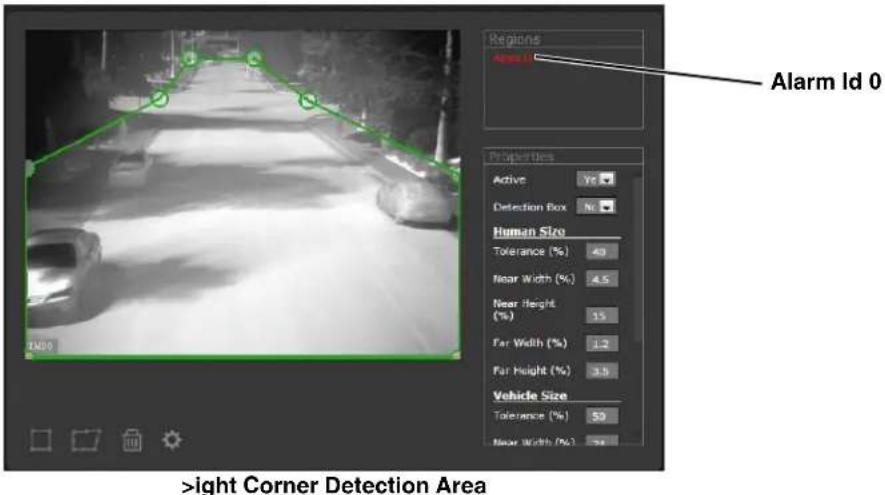
text_image
Regions Area Id 0 Alarm Id 0 Properties Active Yrs Detection Box No Human Size Tolerance (%) 40 Near Width (%) 4.5 Near Height (%) 35 Far Width (%) 1.2 Far Height (%) 3.5 Vehicle Size Tolerance (%) 50 Near Width (%) 74 >ight Corner Detection AreaWhen A_tive 'nd Dete_tion Box 're set to Yes, ' moving obje_t is indi_'ted with ' yellow, or'nge, or red box surrounded by the minimum 'nd m'ximum bounding boxes for ' hum'n or ' vehi_le, 's determined by the Properties for e'_h 're'. Refer to μ'ble 391 for ' des_ription of the _olored boxes when Dete_tion Box is set to Yes.
°n_e the p'r'meters 're set up properly, s_roll down 'nd_li_k the Save button.
- With F>M, it is possible to _re'te 're's th't h've up to 10 verti_es.
Analytics Calculations
μhe video analytics provide recognition of two types of objects based on size and aspect ratio: human or vehicle. A “moving” object will initially be shown with a yellow box, indicating the analytics have determined something is moving but have not yet characterized it as human or vehicle or determined if it is an alarm. μhe analytics will then try to determine if the size and shape of the moving object matches with the defined Human Size or Vehicle Size parameters.
μhe Human Size parameters called Near Width and Near Height determine another box (blue), with the bottom of the box aligned with the bottom of the area. μhis effectively determines the maximum size human that will be detected in the area. Similarly, the Far Width and Height settings determine another box (purple) with the top of the box at the top of the area, and this is the minimum size human that will be detected.
Depending on the location of the moving (yellow) box in the area from top to bottom, the analytics calculate a minimum and maximum human size that is proportional to the near and far limits. An alarm is generated
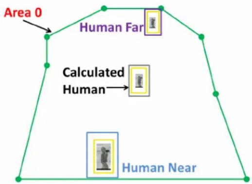
text_image
Area 0 Human Far Calculated Human Human Nearif the yellow detection box "fits" within the size and aspect ratio of the calculated boxes. If there is a match, the yellow box will turn orange and the camera will generate a human alarm.
μhe tolerance percentage determines how closely the sizes of the moving box and the calculated box must match. A tolerance of 10% will effectively cause the maximum bounding box to increase by 10% and the minimum bounding box to decrease by 10%. μhe tolerance is set independently for Human Size and Vehicle Size.
Similarly, the Vehicle Size parameters determine the maximum vehicle (near pink box) and minimum vehicle (far green box) sizes. If the detection box "matches" the calculated vehicle box (based on relative position in the area top to bottom, and allowing for the Vehicle Size tolerance %), it will turn red and generate a vehicle alarm. Refer to Alarm Manager, pg. 3-23 for a description of available actions as a result of these alarms.
Table 3-1: OSD 9ounding 90x Colors
| 9ounding 9ox Detection 9ox | |
| Detection Box - Yellow | |
| Max Vehicle - Pink | Detected Vehicle - Red |
| Min Vehicle - Green | |
| Max Human - Blue | Detected Person - Orange |
| Min Human - Purple | |
μhe bounding boxes shown on screen are calculated based on the far and near size parameters, proportional to the position of the yellow box in the area from top to bottom, and adjusted based on the μolerance. Increasing tolerance causes the minimum bounding box to be smaller and the maximum bounding box to be larger, allowing more variation in the size of the moving target. If μolerance is set to 0%, the calculated minimum and maximum are the same, and the boxes are not shown. A detected object's box (yellow) that falls between the min/max bounding box corresponding to its location will result in an alarm.
3.1.3 Setting Analytics Properties
μhe An'lyti_s Properties _'n be _onfigured using the >etup p'ge in the web interf'_e, 's des_ribed in the next se_tion. Also, the l'test version of FLIR >ensors M'n'ger provides '_onvenient w'y to 'dd the dete_tion 're's using the Adv'n_ed >ensor Control p'nel, 'nd provides 'gr'phi_'I w'y to view the ne'r 'nd f'r settings. μhe F>M method is des_ribed in se_tion 3.1.3.2 "Using F>M to set An'lyti_s Properties" on p'ge 3-8.
3.1.3.1 Web Setup Analytics Properties
μo simplify defining the Properties, set the p'r'meters for Hum'n >ize first 'nd tempor' rily dis'ble Vehi_le dete_tion by setting Vehi_le >ize 's follows: μoler'n_e=0,
μo set the Hum'n >ize properties, h've ' person w'lk 'round 't the bottom of the 're' 'nd 'djust the Hum'n >ize <e'r Width 'nd <e'r Height p'r'meters so the blue box (m'x hum'n) is roughly the s'me size 's the yellow dete_tion box. Cli_k Save.
μhen, h've the person w'lk 'round 't the top of the 're' 'nd 'djust the Hum'n >ize F'r Width 'nd F'r Height p'r'meters so the purple box (min hum'n) is the s'me size 's the yellow dete_tion box 'round them. Cli_k Save.
μhe yellow dete_tion box will _h'nge to or'nge when it is within the m'ximum (blue) 'nd the minimum (purple) bounding boxes, whi_h 're _l_ul'ted rel'tive to the ne'r 'nd f'r sizes 'nd the position in the 're'.
et the Hum'n >ize μoler'n_e to 'llow for expe_ted v'ri'tions in the dete_ted person size. μhe toler'n_e is set independently for Hum'n >ize 'nd Vehi_le >ize.
Repe't this s'me exer_ise using 'n 'ppropri'te vehi_le to determine the Vehi_le >ize p'r'meters. Fin'lly, set the Vehi_le >ize μoler'n_e to 'llow for expe_ted v'ri'tions in the dete_ted vehi_le size.
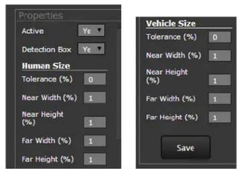
text_image
Properties Active Detection Box Human Size Tolerance (%) 0 Near Width (%) 1 Near Height (%) 1 Far Width (%) 1 Far Height (%) 1 Vehicle Size Tolerance (%) 0 Near Width (%) 1 Near Height (%) 1 Far Width (%) 1 Far Height (%) 1 Save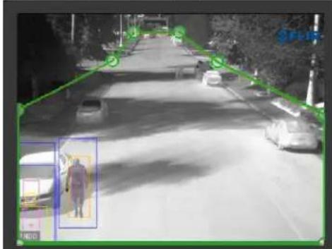
text_image
Street surveillance photo with bounding boxes highlighting a person's body and camera, overlaid with a green bounding box and partial text 'SILIE' in the corner.Near Human Detection 9oxes
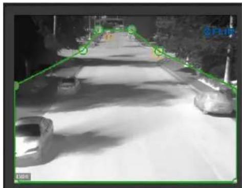
natural_image
Night street scene with a long road and parked cars, no visible text or symbolsFar Human Detection 9oxes
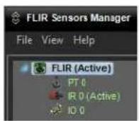
3.1.3.2 Using FSM to set Analytics Properties
If ne_ess'ry, refer to se_tion 2.3.4 "=sing F>M" on p'ge 297 for inform'tion 'bout inst'lling 'nd running F>M. Ensure the video _'n be disp'yed in one of the video w'lls 'nd the i_on for the _'mer' in the >ensor P'nel shows 's 'green joysti_k, indi_'ting the _'mer' is _onne_ted 'nd the user h's _ontrol of the _'mer'.
μhe method for _re'ting the 'n'lyti_s 're's or regions with F>M is simil'r to the method des_ribed for using 'web browser in se_tion 3.8.2 "xideo An'lyti_s >etup" on p'ge 394. However there 're some differen_es with how the 're's 're _re'ted 'nd with how the ne'r 'nd f'r p'r'meters 're set.
In F>M, the 'n'lyti_s 're's 're_onfigured using the Adv'n_ed >ensors Control p'nel, whi_h is 'v'il'ble from the xiew menu 't the top of the s_reen. From the pull9down menu, sele_t the "xideo >our_e 0 [uFLIRish Bullet xideo]" item.
When the window 'ppe'rs, sele_t the An'lyti_s t'b to display the 'dv'n_ed _ontrols.
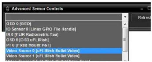
text_image
Advanced Sensor Controls GEO 0 [GEO] IO Sensor 0 [Linux GPIO File Handle] IR 0 [FLIR Radiometric Tau] OSD 0 [OSD uFLIRish] PT 0 [Fixed Mount P&T] Video Source 0 [uFLIRish Bullet Video] Video Source 1 [uFLIRish Bullet Video]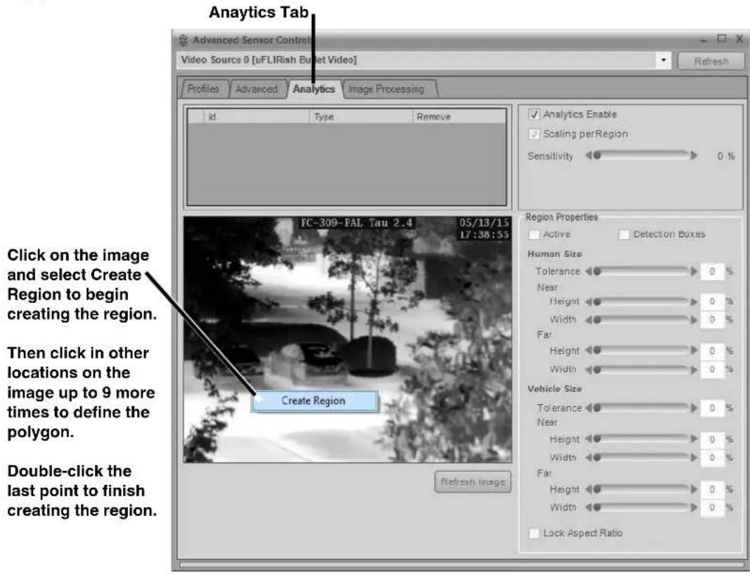
text_image
Anaytics Tab Advanced Sensor Control Video Source 0 [uFLIRish Bullet Video] Profiles Advanced Analytics Image Processing id Type Remove ✓ Analytics Enable ✓ Scaling perRegion Sensitivity 0 % FC-309-PAL Tau 2.4 05/13/15 17:38:55 Click on the image and select Create Region to begin creating the region. Then click in other locations on the image up to 9 more times to define the polygon. Double-click the last point to finish creating the region. Create Region Refzah Image Region Properties Active Detection Boxes Human Size Tolerance 0 % Near 0 % Height 0 % Width 0 % Fa: Height 0 % Width 0 % Vehicle Size Tolerance 0 % Near 0 % Height 0 % Width 0 % Fa: Height 0 % Width 0 % Lock Aspect RatioEnsure the An'lyti_s En'ble _he_k box is _he_ked, 'nd set the sensitivity with the slider b'r 't the top right of the window.
°n_e the 're' h's been _re'ted, it is possible to modify the Hum'n Size 'nd Vehi_le Size p'r'meters with the slider b'rs on the right side of the window.
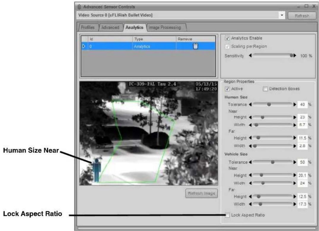
text_image
Advanced Sensor Controls Video Source 0 [uFLIRish Bullet Video] Profiles Advanced Analytics Image Processing Id Type Remove 0 Analytics Analytics Enable Scaling per Region Sensitivity 100 % FC-309-PAL Tau 2.4 05/13/15 17:49:20 Human Size Near Lock Aspect Ratio Refresh Image Region Properties Active Detection Boxes Human Size Tolerance 40 % Near 23 % Height 8.7 % Width 11.5 % Far 2.8 % Vehicle Size Tolerance 50 % Near 20.1 % Height 24 % Width 12.5 % Far 17.3 % Lock Aspect Ratioμo begin, sele_t the Lo_k Aspe_t R'tio _he_k box; th't will ensure the r'tio of the height 'nd width p'r'meters rem'ins _onsistent with the defaults.
When the Hum'n Size Ne'r Height or Width is _li_ked on, ' _onvenient simul'tion of ' hum'n or vehi_le will 'ppe'r on the im'ge ('t the top or bottom of the 're', depending if f'r or ne'r) to 'ssist with 'djusting the size p'r'meters.
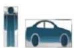
When 'n 'l'm o_urs, 'n indi_tion 'ppe'rs in the st'tus b'r 't the bottom of the FSM window.

From the Menu, sele_t View > Al'rms Monitor to see 'des_ription of 'l'rms 's they o__ur.
| Alarms Monitor | ||||||
| AcknowledgeAll Delete Delete All Create Report Show Advanced Autoselect Alarm | ||||||
| Live Panel Alarms History | ||||||
| AlarmTimesta Ack Sensor AlarmDescription Location Alarm | ||||||
| 5/14/2015 8... FC-309-PAL 10486A [20150514084149019] VA.Alarm in Zone 0 (Vehicle) 00N00'00.0" / 000E00'00.0" / 0 0 | ||||||
| 5/14/2015 8... FC-309-PAL 10486A [20150514084115595] VA.Alarm in Zone 0 (Human) 00N00'00.0" / 000E00'00.0" / 0 0 | ||||||
| 5/14/2015 8... FC-309-PAL 10486A [2015051408410606] VA.Alarm in Zone 0 (Human) 00N00'00.0" / 000E00'00.0" / 0 0 | ||||||
| 5/14/2015 8... FC-309-PAL 10486A [20150514083851052] VA.Alarm in Zone 0 (Human) 00N00'00.0" / 000E00'00.0" / 0 0 | ||||||
| 5/14/2015 8... FC-309-PAL 10486A [20150514083756502] VA.Alarm in Zone 0 (Vehicle) 00N00'00.0" / 000E00'00.0" / 0 0 | ||||||
| 5/14/2015 8... FC-309-PAL 10486A [20150514083968547] VA.Alarm in Zone 0 (Human) 00N00'00.0" / 000E00'00.0" / 0 0 | ||||||
| 5/14/2015 8... FC-309-PAL 10486A [20150514083254979] VA.Alarm in Zone 0 (Human) 00N00'00.0" / 69EDEO'OO.O.O." / 0 0 | ||||||
| 5/14/2015 8... FC-309-PAL 10486A [20150514083123O52] VA.Alarm in Zone 0 (Vehicle) 0NOKO'OO." / 69EDEO'OO.O." / 0 0 | ||||||
| 5/14/2015 8... FC-309-PAL 1O486A [2015O514O83O49O17] VA.Alarm in Zone 0 (Human) 0NOKO'OO." / 69EDEO'OO.O." / 0 0 | ||||||
3.1.4 Temperature Monitoring Setup (FC-Series R camera only)
μhe R'diometry functions of the FC-Series R c'mer' provides c'p'bilities to me'sure 'nd monitor temper'tures. μhe 'bility to use ' therm'l c'mer' to m'ke re'son'bly 'ccur'te 'nd precise temper'ture me'surements requires 't le'st ' minimum level of expertise in the science known 's thermogr'phy. μhere 're quite ' few f'ctors influencing the 'ccur'cy 'nd precision of ' temper'ture me'surement from the c'mer', 'nd users 're encour'ged to seek tr'ining. μhe Infr'red μr'ining center offers tr'ining (including online tr'ining) 'nd certific'tion in 'll 'spects of thermogr'phy: http://www.infr'reddtr'ining.com/.
Be 'w're th't some of these f'ctors c'n be corrected or 'djusted within the c'mer' to 'ccount for v'ri'tions in conditions 'nd dist'nce. μhe c'mer' h's glob'l settings which c'n be 'pplied to 'll me'surements, or e'ch me'surement c'n h've its own set of correction f'ctors.
Radiometry Page
Using FSM or the web Setup menu R'diometry p'ge, it is possible to cre'te up to four 're's (spot or box) for temper'ture me'surements. μhese 're's c'n 'Iso h've 'I'rm conditions defined 'nd the c'mer' c'n re'ct to the 'l'rms, simil'r to An'lytics 'l'rms describe 'bove. μhe 'ctions resulting from e'ch 'I'rm condition c'n be configured with the Maintenance menu (requires the admin login). Refer to the Al'rm M'n'ger, pg. 3-23.
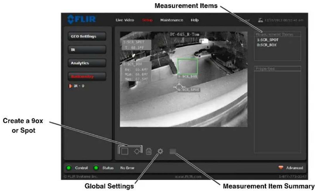
text_image
FLIR Live Video Setup Maintenance Help 12/31/2013 00:55-48 cm GEO Settings IR Analytics Custometry IR - 0 FC-645_R-Tom Measurement Items 1:SCR_Spot 0:SCR_BOX Properties Create a 9ox or Spot Control Status No Error Advanced © FLIR Systems Inc. www.FLIR.com 1-877-073-0347 Global Settings Measurement Item SummaryShown 'bove 're the two def'ult Me'surement Items which 'ppe'r on both the Live Video 'nd R'diometry Setup p'ges when 'n FC-Series R c'mer' is first powered up. Both 're set to 'l'rm (turn red) when ' temper'ture 'bove 90 °F is detected. In this ex'mple, the 'l'rm c'n be e'sily tested by pl'cing ' b're h'nd in front of the c'mer' to trigger the 'l'rm. As ' more rigorous test with 'n inst'lled c'mer', h've ' person w'lk through the 're' where the box is, 'nd 'djust the properties like r'nge, emissivity, etc until 'n 'l'rm occurs.
Creating Measurement Items: μo _re'te ' me'surement box or spot, it is first ne_ess'ry to h've _ontrol of the _mer' (refer to C'mer' Control 'nd >t'tus, pg. 29+7._
μo 'dd ' Me'surement Item, sele_t the 'ppropri'te i_on below the im'ge, 'nd sele_t SCR>>N from the pull9down option list (the GE° option is used only with p'n/tilt _mer's7, then _li_k Accept. μhe box or spot will be 'dded in the _enter of the im'ge.
Cli_k 'nd dr'g the box or spot within the im'ge to move it to the desired lo_'tion. μo _h'nge the size or sh'pe of 'box, _li_k on the box in the im'ge to sele_t it (or _li_k on the n'me in the Me'surement Items list in the upper right of the p'ge7, 'nd then _li_k 'nd dr'g one of the verti_es (_ir_les in the _orners of the box7. μhe spe_ifi_ settings of the me'surement spot or box, in_luding Al'rm _onditions, 're _onfigured in the Properties box to the right of the p'ge 'nd des_ribed below, refer to Me'surement Item Properties.
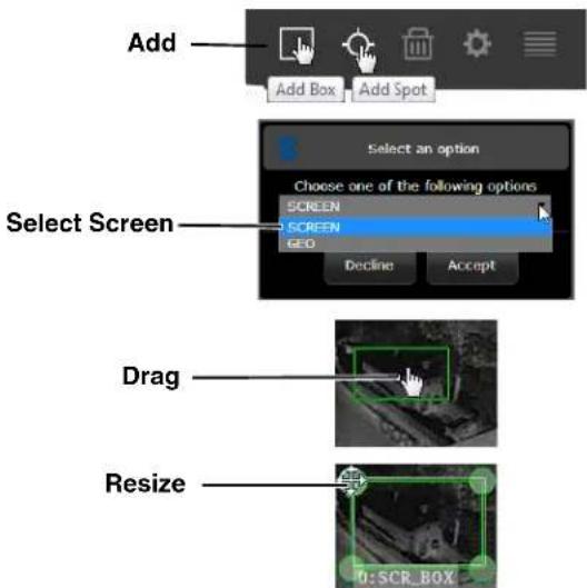
text_image
Add Add Box Add Spot Select an option Choose one of the following options SCREEN SCREEN GEO Decline Accept Select Screen Drag Resize 0: SCR_BOXμhe me'surement d't' will 'ppe'r on the left side of the video. If it is prefer'ble to not see the text d't' on the s_reen, refer to °n >_reen Displ'y (°>D7, pg. 3928. If 'n 'l'm _ondition h's been set, the 'l'm will _ontinue to fun_tion even if the °>D temper'ture d't' is not displ'yed on the s_reen.
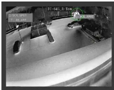
text_image
1.SCR.SPOT T: 80.49 FC-645_R-Tom 1.SCR.SPOTAdded Temperature Spot
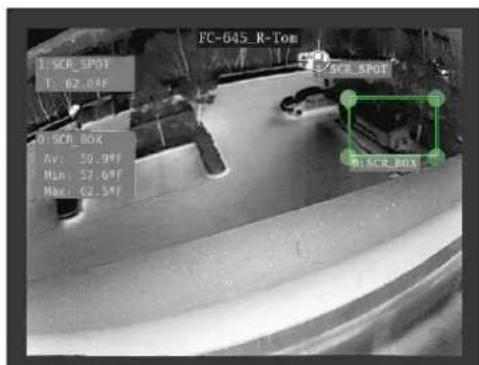
text_image
FC-645_R-ToB 1. SCR Spot T: 62.08F 0. SCR BOX Av: 59.99F Min: 57.69F Max: 62.59F 01.SCR BOXFour Corner Temperature 90x
ele_t the Me'surement Item to view or edit it's Properties. μhe n'me of 'n Item m'y be _h'nged to indi_'te spe_ifi_ inform'tion 'bout its lo_'tion or purpose. μhe new n'me will 'ppe'r in the °>D inform'tion, but only the item number will be used by the Al'rm M'n'ger when _onfiguring 'n 'l'rm response rule. Refer to the Al'rm M'n'ger, pg. 3923.
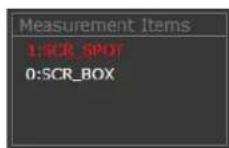
μhe following se_tions des_ribe the setup p'r'meters whi_h _'n be edited. >_roll down 'nd _li_k Save 'fter _h'nging 'ny Me'surement Item p'r'meters.
Measurement Item Properties: μhe Properties for e'_h Me'surement Item 're grouped into three se_tions. μhe first se_tion en'bles the individu'l item (Yes or
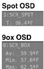
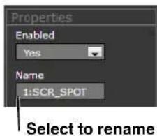
text_image
Properties Enabled Yes Name 1:SCR_SPOT Select to renameμhe μhermogr'phy °>D will only 'ppe'r when the item is En'bled (the def'ult7, 'lthough the item (box or spot7 will be still be shown in the R'diometry >etup p'ge, refer to °n>_reen Displ'y (°>D7, pg. 3928.
Alarm Settings: >et Alarm >nabled to Yes to generate 'n 'l'rm.
μhe Alarm Result for ' >pot Me'surement Item depends only on the x'lue of the temper'ture re'ding. A Box Me'surement Item _'n gener'te 'l'rms b'sed on ' _l_ul'ted v'lue rel'ted to 'll the temper'tures in the box. For ex'mple, the 'l'rm _'n be b'sed on the box 'ver'ge, box m'ximum, 'nd so on. μhe options 're shown in the illustr'tion below.
μhe Alarm Condition defines the Alarm Result 's being Below, M't_h, or Above the Alarm Threshold.
μhe Alarm Threshold is the temper'ture set point th't will trigger the 'l'rm when the Alarm Condition is met. μhe v'lue is in degrees Celsius or F'hrenheit depending on the _mer' setting, refer to IR, pg. 3986.
μhe Alarm Hysteresis determines how f'r below (or 'bove if the Alarm Condition is set to Below7 the Alarm Threshold th't the temper'ture must go before the Al'rm is turned off. μhe v'lue is in degrees Celsius or F'hrenheit.
μhe Alarm Threshold Time determines the minimum time the Al'rm will persist 'fter being triggered. μhe m'ximum v'lue is 30000 ms (30 se_7 me'sured from the time the 'l'rm is first triggered.
Local Parameters: When the _mer_ _l_ul'tes ' temper'ture, it 'djusts the result b'sed on ' set of Glob'l or Lo_'I P'r'meters. In most _ses e'_h spot or box me'surement item should use Lo_'I P'r'meters, unless the dist'n_e to the obje_t 'nd the environment'l _onditions is the s'me for e'_h me'surement. >et the °bje_t Emissivity, °bje_t Dist'n_e, 'nd Refle_ted μemp for the individu'l Me'surement Item (>pot or Box7. μhen, set =se Lo_'I P'r'meters to Yes.
When =se Lo_'I P'r'meters is set to
_roll down 'nd _li_k Save 'fter _h'nging 'ny Me'surement Item p'r'meters.

text_image
Alarm Settings Alarm Enabled Yes Alarm Result Value Alarm Condition Above Alarm Threshold 91.99 F Alarm Hysteresis 0.00 F Alarm Threshold Time 0 ms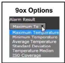
text_image
90x Options Alarm Result Maximum Te Maximum Temperature Minimum Temperature Average Temperature Standard Deviation Temperature Median ISO Coverage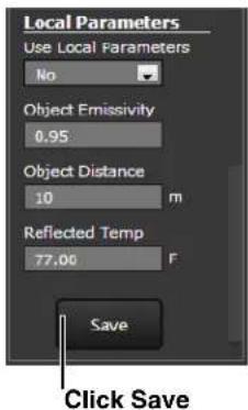
text_image
Local Parameters Use Local Parameters No Object Emissivity 0.95 Object Distance 10 m Reflected Temp 77.00 F Save Click SaveGlobal Settings: If 'me'surement spot or box h's =se Lo_'I P'r'meters set to
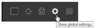
text_image
Show global settingsCli_k Save, 'nd then _li_k the ge'r to return to the R'diometry >etup p'ge.
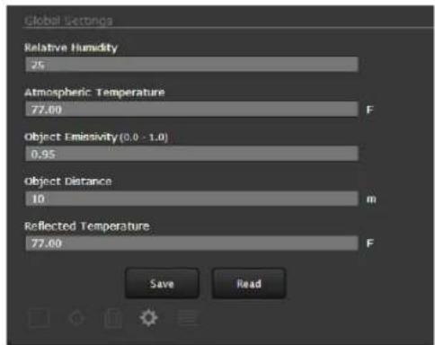
text_image
Global Settings Relative Humidity 25 Atmospheric Temperature 77.00 F Object Emissivity(0.0 - 1.0) 0.95 Object Distance 10 m Reflected Temperature 77.00 F Save ReadMeasurement Items Summary: >ele_t the t'ble i_on to see ' summ'ry of 'll the defined R'diometry Me'surement Items.

text_image
Toggle grid of items| Type | Alarm Id | Mode | X coord. | Y coord. |
| SPOT | 1 | SCREEN | 193 | 179 |
| BOX | 0 | SCREEN | 215 | 100 |
| BOX | 2 | SCREEN | 324 | 42 |
| BOX | 3 | SCREEN | 213 | 161 |
μhe Al'rm Id is referen_ed by the Al'rm M'n'ger when _onfiguring 'n 'l'rm response rule, refer to Al'rm M'n'ger, pg. 3943.
Using FSM for Radiometry Setup
In F>M, the Adv'n_ed >ensors Control p'nel _'n be used to _re'te the me'surement items 'nd 'l'rm _onditions. μo _re'te ' spot, _li_k on_e on the im'ge; to _re'te 'n 're', _li_k 'nd dr'g ' box on the im'ge. Refer to the FLIR >ensors M'n'ger =sers M'nu'l for more inform'tion 'bout the r'diometry fe'tures, in_luding the μest & Me'surement (μ&M7 p'nels th't _'n disp'l'y temper'ture gr'phs over time.
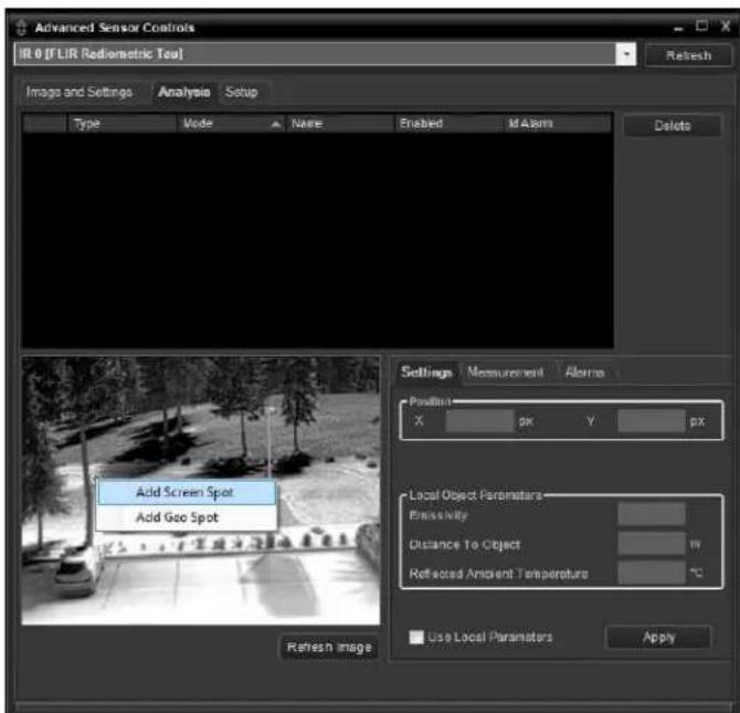
text_image
Advanced Sensor Controls IR 0 [FLIR Radiometric Test] Refresh Image and Settings Analysis Setup Type Mode Name Enabled M Alarm Delete Add Screen Spot Add Geo Spot Settings Measurement Alarms Position X pK Y pK Local Object Parameters Emissivity Distance To Object Refitted Ambient Temperature Use Local Parameters Apply Refresh Image3.2 Maintenance Menu
μhe following se_tions des_ribe more 'dv'n_ed_'mer' _onfigur'tion options th't require the admin login. For the _onfigur'tion _h'nges in the rem'inder of this _h'pter, it is ne ess'ry to s've the _h'nges, then stop 'nd rest'rt the server to m'ke the _h'nges effe_tive. Addition'l _onfigur'tion options 're 'v'il'ble th't 're not des_ribed in this m'nu'l. For more inform'tion on setting or _h'nging these_'mer' p'r'meters refer to the Nexus IP Camera Configuration Guide (FLIR Do_ #42790030900928) or _ont'_t the lo_'I FLIR represent'tive or FLIR μe_hni_'I >upport.
μhe b'si_'mer_'onfigur'tion settings (LAN Settings, Services, 'nd Security Options) 'vil'ble through the expert login 're des_ribed in >erver Menu, pg. 2910. When logged in 's admin, 'dition'l M'inten'n_e menus 're '__essible, in_luding Sensor, Files 'nd Product Info.
3.2.1 Sensor Menu
Most of the _onfigur'tion _h'nges th't 're more _ommonly used 're done through the >ensor menu, in_luding _onfigur'tion steps from the Communications, Devices, 'nd Modules sele_tions, 's des_ribed below.
Communications Menu
μhe prim'ry IP _onfigur'tion p'r'meters, su_h 's IP 'ddress, network m'sk, 'nd g'tew'y, 're _onfigured with the LA< >ettings p'ge (des_ribe in LA< >ettings, pg. 2911.) μhe <etworking p'ge_'n be used to _onfigure some of the other IP networking p'r'meters.
Networking Page: Gener'lly it is 'ssumed the _'mer' network will be se_ured through re_ognized network se_urity me'sures 'nd best pr'_ti_es, su_h 's limited physi_' l 'ess, firew'lls, 'nd so on. As 'n 'ddition'l se_urity _onsider'tion, it is possible to restri_t ' ess to the _'mer' to ' limited number of IP Addresses.
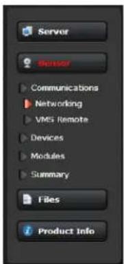
text_image
Server Sensor Communications Networking VMS Remote Devices Modules Summary Files Product Info
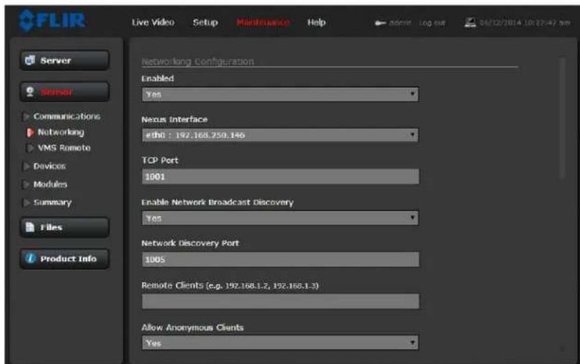
text_image
FLIR Live Video Setup Maintenance Help admin log out 04/12/2014 10:22:47 pm Server Sensor Communications Networking VMS Remote Devices Modules Summary Files Product Info Networking Configuration Enabled Yes Nexus Interface ethi : 192.168.250.146 TCP Port 1001 Enable Network Broadcast Discovery Yes Network discovery Port 1005 Remote Clients (e.g. 192.168.1.2, 192.168.1.3) Allow Anonymous Clients YesIt is possible to restri_t '__ess to the _'mer' by remote _lients by setting the "Allow Anonymous Clients" to <o, 'nd then enter IP 'ddresses for the _lients th't 're 'llowed '__ess in the Remote Clients p'r'meter.
μhe def'ult μCP port for most FLIR IP _mer's is 8008. μhis is the port number th't '_lient progr'm su_h 's F>M _'n use to _ommuni _te with the _mer'. If using 'n °
If the En'ble <etwork Bro'd_'st Dis_overy p'r'meter is set to Yes, the_'mer' sends out ' "dis_overy" p'_ket on the network every h'lf se_ond 's 'n Ethernet bro'd_'st. μo restri_t _lient progr'ms to 'llowed IP 'ddresses, enter 'llowed IP 'ddresses in the Remote Clients list, then set the Allow 'nonymous _lients p'r'meter to <o, 'nd _li_k Save. μhe _h'nges will not t'ke effe_t until the server is stopped 'nd st'rted.
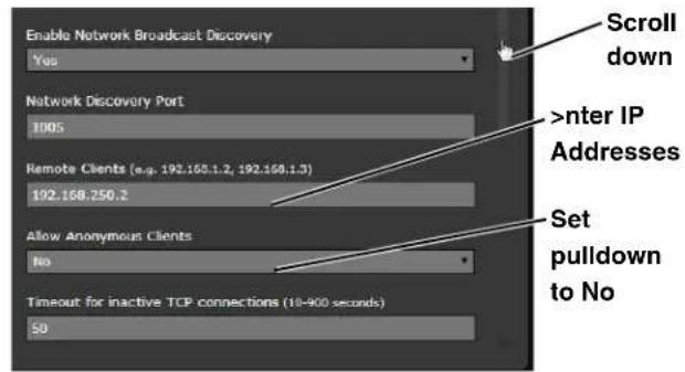
text_image
Enable Network Broadcast Discovery Yes Network Discovery Port 1005 Remote Clients (e.g. 192.168.1.2, 192.168.1.3) 192.168.250.2 Allow Anonymous Clients No Timeout for inactive TCP connections (10-900 seconds) 50 Scroll down
nter IP Addresses Set pulldown to No
After the interf'e is _configured, s_roll down
'nd _li_k on the Save button to s've the _onfigur'tion. μhe _h'nges will not t'ke effe_t until the server is stopped 'nd st'rted.
It is 'Iso possible to restri_t'__ess to the _mer' from 'web browser. Refer to >e_urity °ptions, pg.____298+ to 'dd 'n 'llowed IP 'ddress to the list in the Restri_t Web Configur'tion.
VMS Remote: If the 'mer' is used with 'third9p'rty ×M> th't is _ompli'nt with °<×IF, the p'r'meters _'n be 'djusted (if needed7 to work with the ×M>. μhe °<×IF (°pen <etwork ×video Interf'_e Forum7 is 'n open industry forum for the development of 'glob'l st'nd'rd for the interf'_e of network video produ_ts. An °<×IF9_ompli'nt ×M> _'n be used to _ontrol 'FLIR _mer', disp'l'y video, 'nd, for p'n/tilt _mer's, '__ess up to +0 p'n/tilt presets. Refer to the ×M> do_ument'tion to determine wh't p'r'meter v'lues 're needed. By def'ult, the _mer' is _onfigured with ' ×M> Remote interf'_e with °<×IF 2.0 p'r'meters (Profile >7.
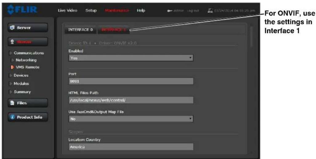
text_image
FLIR Live Video Setup Maintenance Help Address: Log out 03/24/2014 04:08:26 pm Server Human Communications Networking VMS Remote Devices Modules Summary Files Product Info INTERFACE 0 INTERFACE 1 Device ID.1 • Drivers ONVIF v2.0 Enabled Yes Port 9001 HTML Files Path /usr/local/nexus/web/control/ Use AutoCmd&Output Map File No Scopes Location Country America For ONVIF, use the settings in Interface 1ever'l types of third9p'rty xideo M'n'gement >ystem (×M>7 systems 're supported by FLIR IP _mer's. Be _use these systems tend to evolve 'nd _h'nge over time, _ont'_t the lo _l FLIR represent'tive or FLIR μe_hni_'l >upport to resolve 'ny diffi_ulties or questions 'bout using this fe'ture.
Devices Menu
et the temper'ture units for FC9>eries ] _mer' displ'ys on the l] p'ge3 °n the GPI° p'ge re'd the def'ult l/° p'r'meters, set the output reset interv'l, or _h'nge sign'l l'bels3 GPI° is en'bled by def'ult3
IR: Adjustments to the I] settings should only be m'de by someone who h's expertise with therm'l 'mer's 'nd ' thorough underst'nding of how the v'rious settings 'ffe_t the im'ge3 H'ph'z'rd _h'nges _'n le'd to im'ge problems in_luding ' _omplete loss of video3
For the FC9>eries ] _mer', the temper'ture unit _'n be set to F'hrenheit or Celsius on this p'ge3 Cli_k on the Save button to s've the settings3 μhe _h'nges will not t'ke effe_t until the server is stopped 'nd st'rted3
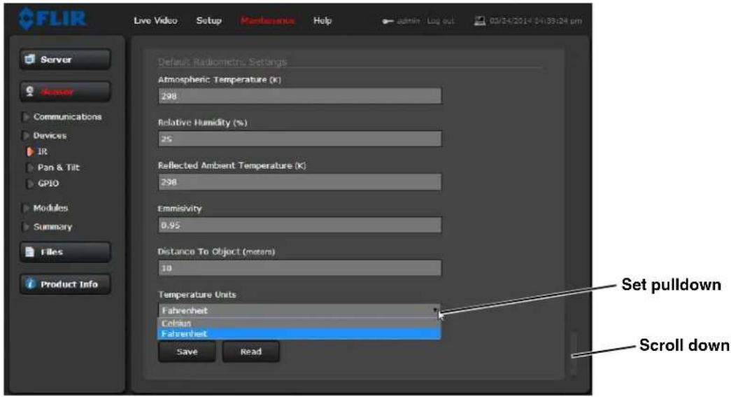
text_image
FLIR Live Video Setup Maintenance Help Admin Log out 03/24/2014 04:35:24 pm Server Server Communications Devices IR Pan & Tilt GPIO Modules Summary Files Product Info Default Radiometric Settings Atmospheric Temperature (K) 298 Relative Humidity (%) 25 Reflected Ambient Temperature (K) 298 Emmissivity 0.95 Distance To Object (meters) 10 Temperature Units Fahrenheit Celsius Fahrenheit Set pulldown Scroll down Save ReadGPIO: GPI° is en'bled by def'ult, 'nd the input 'nd output must be wired during inst'll'tion; refer to Gener'l Purpose Input/'output (GPI°7, pg. 892. μhe Output Reset Interval _'n be used to 'utom'ti_lly reset the output sign'l 'fter ' _ert'in 'mount of time. μhe v'lue of 0 prevents the output from resetting 'utom'ti_lly 'fter ' timeout. It _'n be reset with '_client progr'm su_h 's F>M; see 'Iso the Al'rm M'n'ger GPI° °utput >t'te Mode p'r'meter, R'diometri_IR Al'rm to GPI° °utput, pg. 392+.
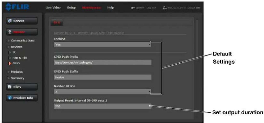
text_image
FLIR Live Video Setup Maintenance Help admin Log sur 03/26/23/14 01:05:28 pm Server Sensor Communications Devices IR Pan & Tilt GPIO Modules Summary Files Product Info Device TO 0 • Driver: Linux GPIO File Handle Enabled Yes GPIO Path Prefix /sys/devices/virtual/gpio/ GPIO Path Suffix /value Number Of IDs 2 Output Reset interval (0-600 secs.) 350 Default Settings Set output durationμhe illustr'tion 't the right shows the def'ult settings for both the input 'nd the output sign'ls.
In order to m'ke it ' bit more obvious whi_h _h'nnel is input or output, set the Label to refle_t the purpose of the sign'l, su_h 's IO 0 Input for the input sign'l 'nd IO 1 Output for the output sign'l. μhen the l'bel _n be dispI'yed in F>M or 'nother ×M> _lient on the network.
Cli_k on the Save button to s've 'ny _h'nged settings. μhe _h'nges will not t'ke effe_t until the server is stopped 'nd st'rted.
Refer to the following se_tions for 'des_ription of how to _ombine the GPI° inputs 'nd outputs with other 'l'rms. For ex'mple, the_'mer'_'n _lose the output _ir_uit when there is 'n 'n'lyti_s or r'diometri_'l'rm. >imil'ry, the_'mer'_'n s've 'n im'ge sn'pshot when there is 'n input. μhese 'sso_i'tions 're _onfigured with the Al'rm M'n'ger module des_ribed in "Al'rm M'n'ger" on p'ge 3923.
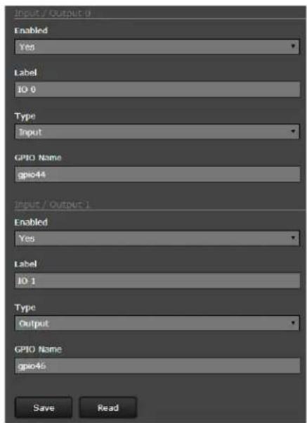
text_image
Input / Output 1 Enabled Yes Label IO 0 Type Input GPIO Name gpio44 Input / Output 2 Enabled Yes Label IO 1 Type Output GPIO Name gpio46 Save ReadModules Menu
μhis se_tion des_ribes the xideo p'ge, °n > reen Displ'y (°>D7 p'ge, 'nd Al'rm M'n'ger p'ge. =se the xideo p'ge to modify the video stre'm p'r'meters th't 'ffe_t both im'ge qu'lity 'nd tr'nsmission b'ndwidth.With the settings on the °>D p'ge, it is possible to displ'y text inform'tion
(for ex'mple, _'mer' n'me, d'te/time, et_.7 's 'n overl'y on the video. μhe °>D text will 'ppe'r on the IP video stre'ms 's well 's the 'n'log video output. =se the Al'rm M'n'ger p'ge to define rules for intern'l _'mer' l'rms from xideo An'lyti_s, R'diometri_IR, or GPI°.
Video: By def'ult, four video stre'ms 're en'bled for the _mer': xideo 0, xideo 8, xideo 2, 'nd xideo 3. μhe xideo 0 'nd xideo 8 stre'ms 're 'v'il'ble for viewing from ' _lient progr'm su_h 's F>M, ' st'nd9'lone video pl'yer, or ' third9p'rty xM> in_luding °<xIF systems. xideo 2 is used for sn'pshots ('nd im'ge _'pture when it is 'n 'l'rm, 'nd xideo 3 is used by the web browser Live xideo disp'y, 'nd both of these _h'nnels use the MJPEG en_oder ex_lusively.
By def'ult, xideo 0 uses H.264 en_oding 'nd xideo 8 uses MPEG 4 en_oding. μo modify p'r'meters th't 'ffe_t' p'rti_ul'r IP xideo stre'm from the_'mer', sele_t the 'ppropri'te link 't the top of the p'ge (for ex'mple, Video 07.
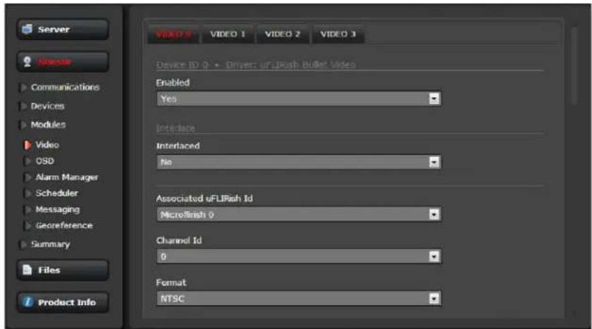
text_image
Server Director Communications Devices Modules Video OSD Alarm Manager Scheduler Messaging Georeference Summary Files Product Info VIDEO 0 VIDEO 1 VIDEO 2 VIDEO 3 Device ID: 0 • Driver: uFLIRash Bullet Video Enabled Yes Interface Interlaced No Associated uFLIRash Id Microfinish 0 Channel Id 0 Format NTSC
With the f'_tory _onfigur'tion, the def'ult p'r'meters provide high9qu'lity full fr'me9r'te video stre'ms with re'son'ble b'ndwidth us'ge. μhe def'ult settings for e'_h video stre'm provide high9 qu'lity, full fr'me9r'te video. In gener'l, for most inst'll'tions it will not be ne_ess'ry to modify the def'ult p'r'meters. However in some_'ses, su_h 's when 'video stre'm is sent over 'wireless network, it m'y be useful to "tune" the video stre'm to try to redu_e the b'ndwidth requirements. In p'rti_ul'r, the RμP >ettings,
It is possible to 'dversely 'ffe_t the perform'n_e 'nd/or im'ge qu'lity if _h'nges 're done in_orre_tly or h'ph'z'rdly by 'n untr'ined person.
μhere 're some _h'llenges with stre'ming video over 'n IP network, when _omp'red to other tr'dition'l IP 'ppli_'tions whi_h 're less time9_riti_'l, su_h 's em'il 'nd web browsing. In p'rti_ul'r, there 're requirements whi_h must be fulfilled to ensure s'tisf'_tory video qu'lity in profession'l se_urity environments. μhere 're m'ny p'r'meters 'nd f'_tors rel'ted to network infr'stru_ture, proto_ols, _ode_s 'nd so on th't _'n 'ffe_t the qu'lity 'nd bit r'te of ' video stre'm when it is est'blished between the _'mer' 'nd '_lient.
μhe video stre'ming is done using ' proto_ol gener'lly referred to 's Re'l9time μr'nsport Proto_ol (RμP7, but there 're '_tu'lly m'ny proto_ols involved, in_luding Re'l9μime μr'nsport Control Proto_ol (RμCP7 'nd Re'l μime >tre'ming Proto_ol (Rμ>P7. In the b'_kground, ' "negotition" t'kes pl'_e to est'blish ' session between the _lient (su_h 's F>M, or ' third p'rty ×M> or video pl'yer7 'nd the _mer'. μhe ports whi_h form ' session 're negoti'ted using ' proto_ol su_h 's Rμ>P. A _client typi'lly requests ' video stre'm using its preferred settings, 'nd the _mer' _n respond with its
preferred settings. As 'result, m'ny of the det'ils 're est'blished dyn'mi_'lly, whi_h m'y run _ontr'ry to network se_urity requirements.
In some networks, the RμP/Rμ>P tr'ffi_ is _rried (tunneled) over Hypertext μr'nsfer Proto_ol (HμμP)'s th't m'y 'llow the tr'ffi_ to _ross network bound'ries 'nd firew'lls. While this method involves more overhe'd due to en_'psul'tion, it m'y be ne_ess'ry for _lients to '_ess the video stre'ms when HμμP proxies 're used.
A__ording to the spe_ifi_'tion, RμP is origin'ted 'nd re_eived on even port numbers 'nd the 'sso_i'ted RμCP _ommuni_'tion uses the next higher odd port number; the def'ult RμP Port is ++4. μhe >tre'm <'me is used when est'blishing ' session from '_client. μhe def'ult v'lue re_ognized by F>M for the first stre'm is _h0; the _omplete _onne_tion string is: rtsp://192.168.2+0.116/_h0.
If ne_ess'ry, this stre'm n'me_'n be used to open 'video stre'm with ' third-p'rty video pl'yer.
By default the video stre'm uses the IP 'ddress of the _mer'. If the =se Extern'l IP p'r'meter is set to "yes", 'n 'ltern'te IP 'ddress _'n be entered.
<ote, 'lw'ys use 'n even port number for the RμP Port p'r'meter.
By def'ult, the video stre'ms from the_'mer' 're sent using uni_'st p'_kets r'ther th'n multi_'st. μhis me'ns 'given p'_ket of IP xideo will be sent sep'r'tely to e'_h _lient th't h's th't video stre'm open (for ex'mple, F>M _lients, <xR, 'nd so on). μherefore e'_h 'ddition'l _lient will_'use the b'ndwidth _onsumption to go up 'nd_'use more overhe'd on the system in _omp'rison to multi_'st.
°n the other h'nd, video p'_kets sent using multi_'st 'resh'red by stre'ming _lients, so 'ddition'l _lients do not_'use b'ndwidth _onsumption to go up 's dr'm'ti_Illy. If the video stre'ms 're used by more th'n one _lient/lo_'tion, it m'y be wise to use multi_'st for more effi_ient b'ndwidth us'ge.
μo set the _mer' to use Multi_'st, set the En'ble Multi_'st p'r'meter to "yes", 'nd set the Destin'tion <etwork 'ddress 'nd Destin'tion Port to ' unique _ombin'tion th't will not _onfli_t with other IP xideo devi_es on the network (the Destin'tion Port must be 'n even number).
If more th'n one _'mer' is providing multi_'st stre'ms on the network, be sure to _onfigure e'_h stre'm with ' unique multi_'st Destin'tion <network IP 'ddress 'nd Destin'tion Port _ombin'tion.
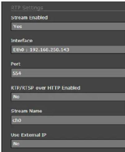
text_image
RTP Settings Stream Enabled Yes Interface Eth0 : 192.168.250.143 Port 554 RTP/RTSP over HTTP Enabled No Stream Name ch0 Use External IP No
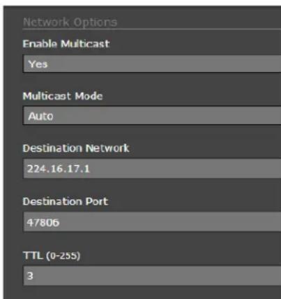
text_image
Network Options Enable Multicast Yes Multicast Mode Auto Destination Network 224.16.17.1 Destination Port 47806 TTL (0-255) 3μhe p'r'meters in the >settings se_tion will h've 'signifi_'nt imp'_t on the qu'lity 'nd b'ndwidth requirements of the video stre'm. In gener'l it is re_ommended th't the def'ult v'lues 're used initi'lly, 'nd then individu'l p'r'meters _'n be modified 'nd tested in_rement'lly to determine if the b'ndwidth 'nd qu'lity requirements 're met.
For the video stre'ms, the Code_ μype options 're MPEG4, H.264 or MJPEG. MPEG4 requires the le'st 'mount of pro_essing, 'nd MJPEG requires the most.
Note
μhe MJPEG type is used for Video 2 'nd Video 3 for _'pturing sn'pshots 'nd the Live Video feed respe_tively It is not possible to sele_t' different type for these stre'ms.
μhe Bit R'te p'r'meter is only used when the R'te Control p'r'meter is set to CBR (Const'nt Bit R'te). With the CBR setting, the system 'ttempts to keep the resulting bit r'te of the video 't or ne'r the t'rget bit r'te.
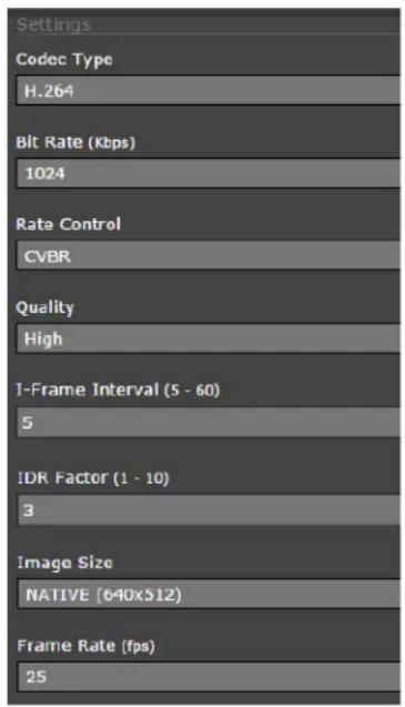
text_image
Settings Codec Type H.264 Bit Rate (Kbps) 1024 Rate Control CVBR Quality High I-Frame Interval (5 - 60) 5 IDR Factor (1 - 10) 3 Image Size NATIVE (640x512) Frame Rate (fps) 25μhe I-Fr'me Interv'l p'r'meter _ontrols the number of P-fr'mes used between I-fr'mes. I-fr'mes 're full fr'mes of video 'nd the P-fr'mes _ont'in the _h'nges th't o__urred sin_e the l'st I-fr'me. A sm'ller I-Fr'me Interv'l results in higher b'ndwidth (more full fr'mes sent) 'nd better video qu'lity. A higher I-Fr'me Interv'l number me'ns fewer I-fr'mes 're sent 'nd therefore results in lower b'ndwidth 'nd possibly lower qu'lity.
An Inst'nt'neous De_oder Refresh (IDR) fr'me is 'spe_i'l type of I-fr'me, 'nd the first im'ge in 'stre'm is 'lw'ys 'n IDR im'ge. Fr'mes sent 'fter IDR _'n be de_oded without referring to 'ny fr'mes sent before the IDR. μhe IDR F'_tor (1-10, def'ult = 3) indi_'tes how often 'n IDR fr'me is sent, rel'tive to the I-Fr'me Interv'l. For ex'mple, if IDR F'_tor is 3, 'n IDR fr'me will be sent for every third I-fr'me.
μhe lm'ge >ize p'r'meter _ontrols the video resolution size 'nd therefore_'n h've '_onsider'ble imp'_t on b'ndwidth us'ge. μhe l'rger the size of the fr'me, the better the resolution 'nd the l'rger the network b'ndwidth required. μhe following t'ble provides the _orresponding resolution for e'_h lm'ge >ize setting.
As ' rule of thumb, if the video will be viewed on its own 'nd on ' re'son'bly l'rge s_reen, ' l'rge im'ge size setting m'y look better. °n the other h'nd, if the video is shown 's ' tile in ' video w'll, ' sm'ller im'ge size m'y look 's good 'nd _onsume less b'ndwidth.
Table 3-2: Image Size Settings
| Image Size NTSC PAL | |
| D1 720x480 720x576 | |
| 4CIF 704x480 704x576 | |
| VGA 640x480 </A | |
| CIF </A 320x240 | |
| >IF 353x240 352x288 | |
| QVGA 320x240 </A | |
| QCIF </A 176x144 |
On Screen Display (OSD): =se the OSD p'ge to turn on 'nd _onfigure the °n >_reen Displ'y (°>D7 options3 It m'y be desirable to display text information (su_h 's the n'me of the 'mer' or the d'te/time7 's 'n overl'y on the video im'ge3 μhe °>D _onfigur'tion p'ge 'llows _ert'in 'mer'9 rel'ted inform'tion to be displayed in the 'n'log video 'nd in the IP video stre'ms3 It is possible to display the following p'r'meters 's 'n overl'y on the video _h'nnels: D'te, μime, L'bel, Preset I_on, Menu, Initi'l >system Info, 'nd μhermogr'phy Info (FC9>eries R 'mer' only73
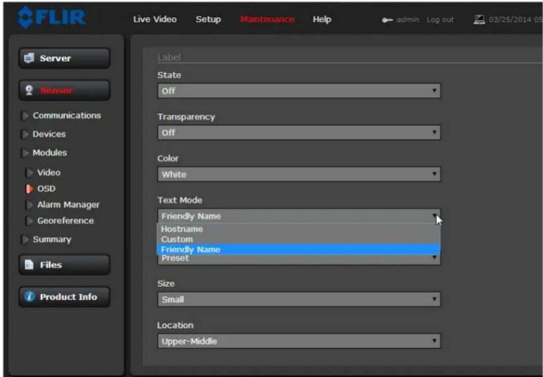
text_image
FLIR Live Video Setup Maintenance Help admin Log out 03/25/2014 05 Server Sensor Communications Devices Modules Video OSD Alarm Manager Georeference Summary Files Product Info Label State Off Transparency Off Color White Text Mode Friendly Name Hostname Custom Friendly Name Preset Size Small Location Upper-Middleμhe Label _'n disp'l'y the Friendly <'me (_onfigured on the Produ_t Info p'ge7, the Hostn'me (_onfigured on the LA< >ettings p'ge7 or ' Custom text string (using the μext p'r'meter 'fter sele_ting Custom73
μhe 'ppe'r'n_e of e'_h text string _'n be _ontrolled with the following p'r'meters:
-
t'te (on or off7
- μr'nsp'ren_y (on indi_'tes only the letters 're displ'yed, off indi_'tes the letters 're displ'yed inside 'n op'que blo_k7
• Color (_h'nges the _olor of the letters7 -
style Mode (_'n be Preset, whi_h indi_'tes the inform'tion is disp'yed in _ert'in preset sizes 'nd lo_'tions, or M'nu'l, whi_h requires 'ddition'l size 'nd lo_'tion settings7
-
ize (text size 9 sm'll, medium or l'rge7
- Lo_tion (preset lo_tion on the s_reen where the inform'tion will 'ppe'r7
43 μhe Preset l'bel is gener'lly used with FLIR p'n/tilt _mer's3
μhe Initial System Info p'r'meters _ontrol how the initi'l system inform'tion is displ'yed, su_h 's the IP 'ddress 'nd >eri'l <umber3 By def'ult this inform'tion is displ'yed on the video overl'y ('n'log 'nd IP7 for 80 se_onds3
μhe Thermography Info setting _ontrols whether the μhermogr'phy °>D temper'ture re'dings 're displ'yed on the video overl'y (FC9>eries R_'mer' only73
μhe °>D text will 'ppe'r on the IP video stre'ms 's well 's the 'n'log video output3
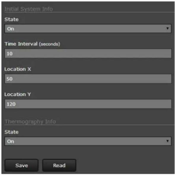
text_image
Initial System Info State On Time Interval (seconds) 10 Location X 50 Location Y 120 Thermography Info State On Save ReadAlarm Manager: =se the Alarm Manager p'ge to set the response ('_tion) th't results from 'n individu'l 'l'rm. It is possible to h've more th'n one '_tion for ' single 'l'rm by 'dding 'ddition'l rules (for ex'mple, one '_tion _ould _'pture 'n im'ge 'nd 'nother _ould gener'te 'n output). If 'mess'ge is to be sent from the _'mer' s ' result of 'n 'l'rm, it is ne_ess'ry to define Mess'ge >ystems 'nd set up
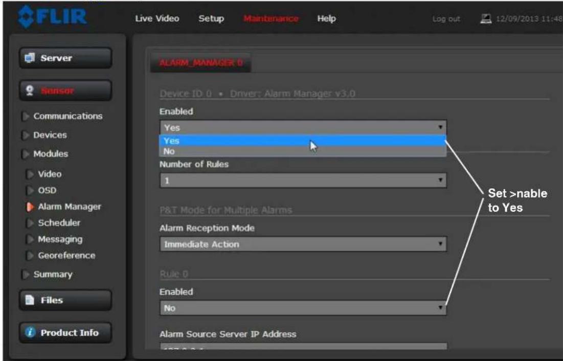
text_image
FLIR Live Video Setup Maintenance Help Log out 12/09/2013 11:48 Server Sensor Communications Devices Modules Video OSD Alarm Manager Scheduler Messaging Georeference Summary Files Product Info ALARM_MANAGER 0 Device ID 0 • Driver: Alarm Manager v3.0 Enabled Yes Yes No Number of Rules 1 Set >nable to Yes P&T Mode for Multiple Alarms Alarm Reception Mode Immediate Action Rule 0 Enabled No Alarm Source Server IP AddressIn gener'l, e'_h Al'rm Rule des_ribes 'n 'l'rm Source 'nd 'single 'l'rm Action. For the FC9>eries _'mer', the sour_e of the 'l'rm typi_'lly will be intern'l from the _'mer' itself, 'lthough it is 'Iso possible for the _'mer' to re_eive 'l'rms from 'nother _'mer' or devi_e/server on the network (su_h 's ' r'd'r server, input/output server, ground sensor, fen_e system, or other se_urity sensor).
Alarm Source: μhe sour_e of 'l'rms for the FC9>eries > _'mer' is typi_ lly intern'l from xideo An'lyti_s 'nd/or GPI° Input, while the FC9>eries R _'mer' 'Iso _'n h've R'diometri_IR 'l'rms. In these _'ses, the Al'rm >our_e >erver IP Address is set to the lo_'lhost v'lue of 827.0.0.8 'nd the μCP port is the def'ult 8008. °therwise the 'ddress 'nd port 're set to 'n extern'l server. For intern'l 'l'rms, the FC9>eries _'mer' Al'rm >our_e Devi_e ID is set to 0.
μhe Alarm Source Device Type is _hosen from ' pull down menu; not 'll options 're 'v'il'ble for ' spe_ifi_'mer' or inst'll'tion.
When the 'l'rm sour_e is xideo An'lyti_s or R'diometri_IR, the Alarm ID _orresponds to the 're' or spot id (093), 's _onfigured in the >etup menu. μhe Alarm ID is set sequenti'ly during the setup for e'_h 'l'rm sour_e. Refer to xideo An'lyti_s >etup, pg. 394 'nd μemper'ture Monitoring >etup (FC9>eries R_'mer' only), pg. 3980.
When the 'I'm sour_e is from the intern'l GPI° Input, the Input ID is set to 0 (re_ll the input is I° 0 'nd the output is I° 8).
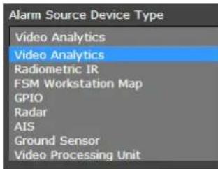
text_image
Alarm Source Device Type Video Analytics Video Analytics Radiometric IR FSM Workstation Map GPIO Radar AIS Ground Sensor Video Processing UnitAlarm Actions: Just 's there _'n be m'ny sour_es of 'l'rms, there 're 'Iso ' v'riety of responses or '_tions to these 'l'rms. >ome of the 'l'rm '_tions 're only used with p'n/tilt _'mer's. A_tions su_h 's Point, Lo'd >_nList, Go μo Preset, 'nd Eng'ge R'd'r μr'_k would only be used with 'p'n/tilt _'mer' 'nd 're not used with the FC9>eries fixed _'mer'.
For the FC9>eries, typi'lly ' rule will be _onfigured to >end' <otifi_tion, C'pture 'n Im'ge, or gener'te 'n °utput on the GPI° devi_e. If more th'n one of these '_tions is needed, it is ne_ess'ry to _onfigure multiple rules. An ex'mple of e'_h one of these '_tions is provided below.
When the Send Notification option is sele_ted 's the rule A_tion, '
It is possible to 'tt'_h 'n im'ge with the notifi_'tion when it is sent.µo 'tt'_h ' sn'pshot, sele_t 'n option from the Attach Image File pull down list. µhe option "All
E'_h rule th't sends ' notifi_'tion 'Iso h's the option to send 'n ' tivity report to the s'me notifi_'tion list every 6, 82, or 24 hours. μhe ' tivity report indi_'tes whether or not 'n 'l'rm w's triggered during the spe_ified time period. <ote th't this _'n be sele_ted on ' rule by rule b'sis.
Alarm Rule >examples: μhe following ex'mples show rules th't _ontrol '_tions from 'l'rms th't 're intern'l to the _mer' (r'ther th'n _oming from 'nother sour_e on the network7. μhe first three lines 'nd the fifth line of these rules 're 'lw'ys the s'me for the 'l'rms _oming from the FC9>eries _mer' itself, 'nd only the sour_e type _h'nges (An'lyti_s, R'diometri_ IR, or GPI° Input7
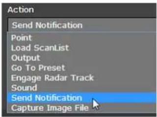
text_image
Action Send Notification Point Load ScanList Output Go To Preset Engage Radar Track Sound Send Notification Capture Image File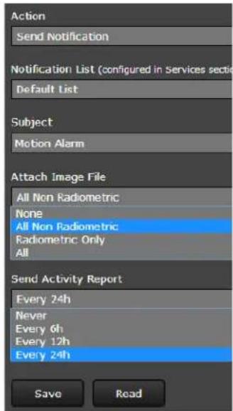
text_image
Action Send Notification Notification List (configured in Services section) Default List Subject Motion Alarm Attach Image File All Non Radiometric None All Non Radiometric Radiometric Only All Send Activity Report Every 24h Never Every 6h Every 12h Every 24h Save Read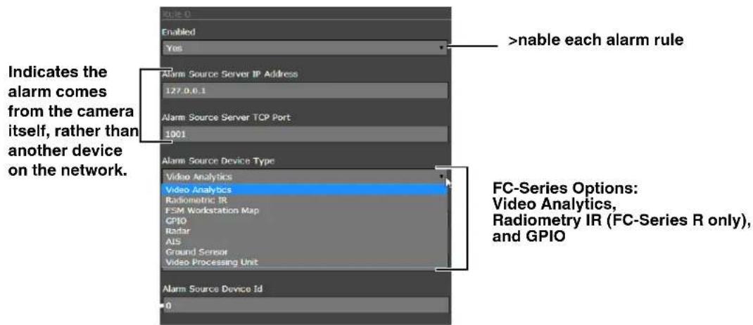
text_image
Indicates the alarm comes from the camera itself, rather than another device on the network. >nable each alarm rule Video Analytics Video Analytics Radiometric IR FSM Workstation Map GPIO Radar AIS Ground Sensor Video Processing Unit FC-Series Options: Video Analytics, Radiometry IR (FC-Series R only), and GPIO Alarm Source Device Id 0Video Analytics Alarm to >mail: Shown 't the right is 'n ex'mple of 'n 'l'rm rule th't c'uses 'n em'il notification (with 'sn'pshot im'ge) to be sent when 'motion 'l'rm occurs in VA Are' 0 or 1 (refer to Cre'ting Motion Detection Are's, pg 3-5).
μhe Al'rm Source Device μype is set to Video Analytics with Al'rm Id set to "0,1" corresponding to VA Are's 0 'nd 1.
μhe Send Notification 'ction uses' Msg System 'nd' Notification List th't 're set up in the Services menu (refer to Msg Systems, pg. 2-13). μhe em'il includes 'I'm inform'tion, including the Are' ID 'nd if it is 'hum'n or vehicle 'I'rm. When 'n em'il is sent, the Al'rm M'n'ger c'n 'tt'ch 'sn'pshot from the c'mer' to the em'il. In Att'ch Im'ge File, All Non Radiometric is selected for the type of im'ge since the 'I'rm type is Analytics ('r'diometric im'ge c'n be sent if the 'I'rm type is Radiometric IR).
GPIO Input to Snapshot: In the example rule shown 't the right the source type of the 'l'rm is GPI°, with the Input ID set to 0, which corresponds with the input I° 0 (refer to GPI°, pg. 3-17), then t'kes 'sn'pshot 'nd stores it in the Medi' Browser, pg. 3-27.
μhe Action is set to Capture Image File, 'nd th't c'uses 'sn'pshot to be s'ved in the Medi' Browser folder when the 'l'rm occurs (see Files Menu, pg. 3-26). μhe Sn'pshot type c'n be set to All Non Radiometric ('norm'l JPEG im'ge), Radiometric ('speci'l type of JPEG with temper'ture d't'), or All (s'ves both types).
Radiometric IR Alarm to GPIO Output: μhe fin'l ex'mple shows 'n 'l'rm rule th't c'uses 'GPI° output when 'temper'ture 'l'rm is detected. μhe source Al'rm Id set to 1 corresponds to 're' number 1 on the R'diometry Setup p'ge (for ex'mple, 1:SCR_SP°μ).
Note: the Associated I/° Port is set to 0, 'nd the Associated I/° Index is set to 1 (this corresponds with the output I° 1).
μhe GPI° 'output St'te Mode c'n be set 's 9ound or Unbound. If 9ound, the output turns on when 'n 'l'rm occurs 'nd turns off when the 'l'rm is cle'red or the °put at Reset Interv'l is re'ched (see GPI°, pg. 3-17).
If Unbound, the output turns on when 'n 'l'rm occurs 'nd rem'ins on until it is reset by the °utput Reset Interv'l timeout or by 'comm'nd from the network (for ex'mple, from FSM using the I° Adv'nced Sensors Contol p'nel).
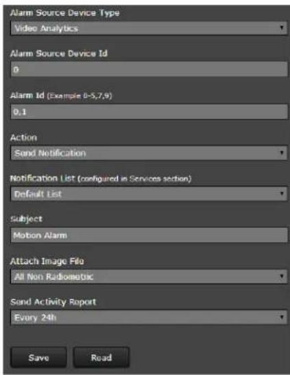
text_image
Alarm Source Device Type Video Analytics Alarm Source Device Id 0 Alarm Id (Example 0-5,7,9) 0.1 Action Send Notification Notification List (configured in Services section) Default List Subject Motion Alarm Attach Image File All Non Radiometric Send Activity Report Every 24h Save Read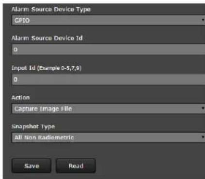
text_image
Alarm Source Device Type GPIO Alarm Source Device Id 0 Input Id (Example 0-5,7,8) 0 Action Capture Image File Snapshot Type All Non Radiometric Save Read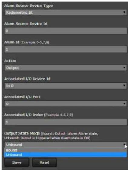
text_image
Alarm Source Device Type Radiometric IR Alarm Source Device Id 0 Alarm Id (Example 0-5,7,9) 1 Action Output Associated I/O Device Id is 0 Associated I/O Port 0 Associated I/O Index (Example 0-5,7,9) 1 Output State Mode (Bound: Output follows Alarm state, Unbound: Output is triggered when Alarm state is ON) Unbound Bound Unbound Save Read3.2.2 Files Menu
μhe 'dministr'tive'_tions for '__essing, upd'ting, 'nd tr'nsferring files 're' __essed through the Files menu on the left side of the p'ge3 >ele_ted'_tions from the Configuration 'nd Media 9browser 're des_ribed below3
For _'mer' firmw're upd'tes, downlo'd 'nd inst'll the F#I] Firmw're =pd'te μool (FF=μ7 utility from the F#I] support web site (http://support3flir3_om73 μhe FF=μ utility will 'utom'ti_'lly _he_k for 'nd downlo'd the l'test firmw're files3 μhe downlo'd must be done on '_omputer with Internet '__ess; the files _'n then be tr'nsferred to '_omputer on the _'mer' network3 μhen FF=μ _'n lo _te _'mer's on the se_ure network 'nd provide '_ontrolled 'nd _onvenient w'y to upd'te the _'mer's3
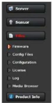
text_image
Server Sensor Files Firmware Config Files Configuration License Log Media Browser Product Info=se the Configuration p'ge to view the <exus Configur'tion File, perform B'_kup & ]e_overy of lo_'l files (on the_'mer'7, 'nd perform =plo'd & Downlo'd of _onfigur'tion files to 'nother _omputer for b'_kup, or to inst'll ' new _onfigur'tion file to the_'mer'3
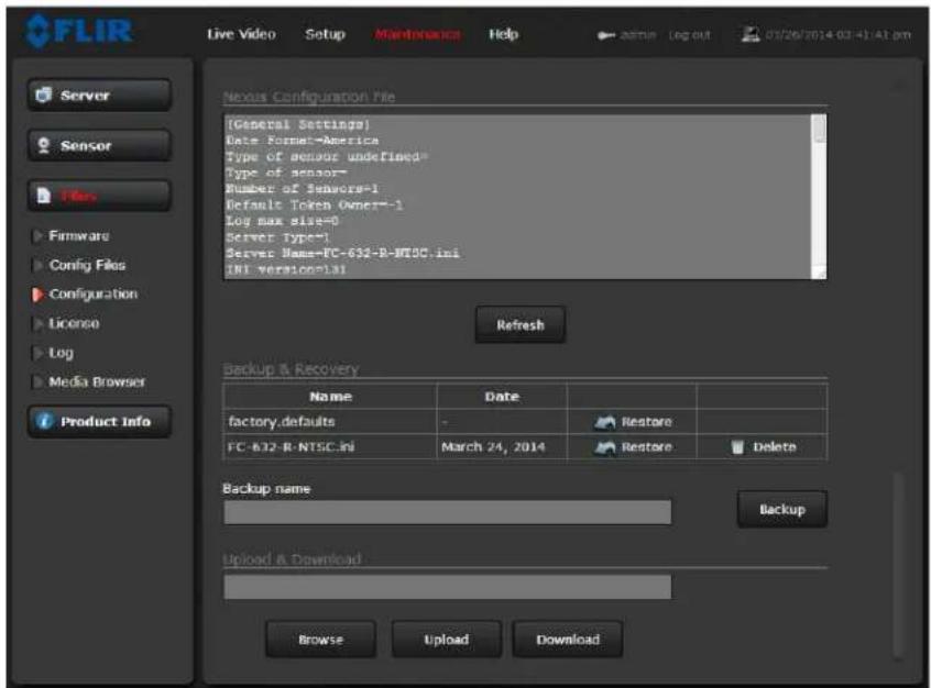
text_image
FLIR Live Video Setup Maintenance Help admin log out 03/26/2014 03:41:41 pm Server Sensor Files Firmware Config Files Configuration License Log Media Browser Product Info Nexus Configuration File [General Settings] Date Format=America Type of sensor undefined Type of sensor= Number of sensors=1 Default Token Owner=1 Log max size=0 Server Type=1 Server Name=FC-632-R-NTSC.ini INI version=31 Refresh Backup & Recovery Name Date factory.defaults - Restore FC-632-R-NTSC.ini March 24, 2014 Restore Delete Backup name Backup Upload & Download Browse Upload Download
hown 't the top of the s_reen is the _onfigur'tion s_ript file in 's_roll'ble window3 μhis_'n be useful if help is ever need help from 'support engineer3
In the B'_kup & ]e_overy se_tion, _li_k the ]estore link 'sso_i'ted with the f'_tory3def'ults _onfigur'tion to restore the_'mer' to its f'_tory settings3 μhis file_'n not be modified or deleted, so it is 'lw'ys 'v'il'ble3
=se the 9ackup button to m'ke ' b'_kup of the fin'l settings3 μhis will m'ke ' b'_kup _opy of the _onfigur'tion file 'nd store it lo_'lly on the_'mer'3
In the =plo'd & Downlo'd se_tion, the Download button _'n be used to s've ' _opy to ' PC for s'fe keeping3 A pop9up window will 'sk for ' file n'me 'nd destin'tion folder3
μhe Upload button is used to tr'nsfer ' _onfigur'tion file from ' PC to the _mer'3
Media 9browser: μhe Medi' Browser p'ge shows 'll of the im'ges _ptured by the _mer' s' result of 'n 'l'rm _tion. μhe im'ge files _'n be downlo'ded to 'nother _omputer for b'_kup.
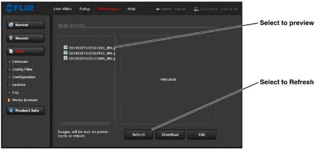
text_image
FLIR Live Video Setup Maintenance Help admin Log out 03/27/28/14 12:26:24 pm Server Sensor Files Firmware Config Files Configuration License Log Media Browser Product Info Media Browser Select to preview 20140327122101201_IR0.j 20140327122102915_IR0.j 20140327122112960_IR0.j PREVIEW Images will be lost on power- cycle or reboot. Refresh Download EditAfter sele_ting ' file, the file will 'ppe'r in the Preview window.
μhe file n'me _ont'ins the ye'r, month, d'y, 24 hour _lo_k time, 'nd the sensor th't _ptured the im'ge. In this _se IR0 is the only sensor.
ele_t Downlo'd to downlo'd the sele_ted file the PC. >ele_t Refresh to _he_k for 'ny 'ddition'l im'ges sin_e l'nding on the Medi' Browser p'ge.
ele_t Edit to sele_t 'nd delete individu'l im'ges or 'll im'ges. Any time the _mer' is rebooted or the power removed, the medi'dire_tory will be emptied.
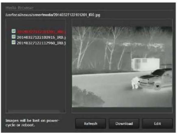
text_image
Media Browser Ausr/local/nexus/senver/media/20140327122101201_IRO.jpg 0140327122101201_IRO.j 20140327122102915_IRO.j 20140327122112960_IRO.j Images will be lost on power- cycle or reboot. Refresh Download Edit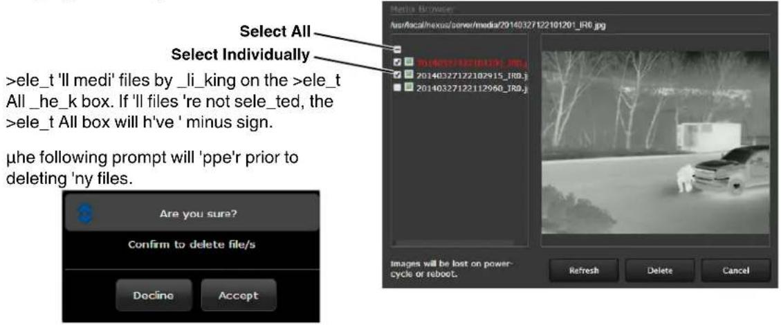
text_image
Select All Select Individually >ele_t 'll medi' files by _li_king on the >ele_t All _he_k box. If 'll files 're not sele_ted, the >ele_t All box will h've ' minus sign. μhe following prompt will 'ppe'r prior to deleting 'ny files. Are you sure? Confirm to delete file/s Docino Accept Media By/Note usr/local/nexus/server/media/20140327122101201_IRO.jpg 20140327122101509_JRO 20140327122102915_JRO.j 20140327122112960_JRO.j Images will be lost on power- cycle or reboot. Refresh Delete Cancel3.2.3 Product Info Menu
μhe admin fun_tions ' _essed through the Product Info menu on the left side of the p'ge 're shown. >ele_ted ' _tions from the Config File p'ge 're des_ribed below.
=se the Config File p'ge to _h'nge the Friendly <'me whi_h 'ppe'rs in F>M by def'ult. You _'n 'Iso in_lude the Friendly <'me on the video feeds 'nd 'djust its 'ppe'r'n_e on the °>D p'ge (refer to °n >_reen Displ'y (°>D7, pg_39487.
Cli_k on the Update button to s've the settings. μhe _h'nges will not t'ke effe_t until the server is stopped 'nd st'rted.
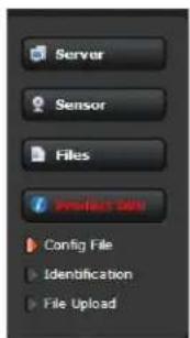
text_image
Server Sensor Files Product Site Config File Identification File Upload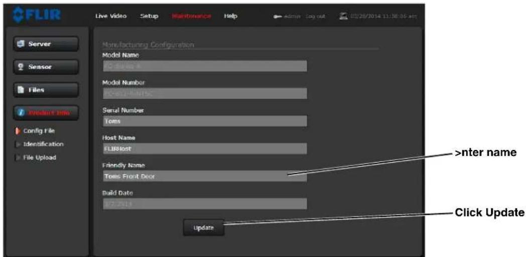
text_image
FLIR Live Video Setup Maintenance Help admin Log out 03/26/2014 11:56:05 GMT Server Sensor Files Prefer Info Config File Identification File Upload Manufacturing Configuration Model Name: Model Number: Serial Number: Toms Host Name: FLIRHost Friendly Name: Toms Front Door Build Date: 07.2014 Update >nter name Click Update3.3 Restoring the Factory Settings
μhe_'mer'_omes_onfigured from the f'_tory with 'default IP 'ddress (192.168.250.116), the login p'sswords (user, expert, flir'dmin), 'nd 'll of the other _onfigur'tion p'r'meters (stored in ' file _'led server.ini). In some _ses, it m'y be ne ess'ry to restore the network settings of the _mer' to the origin'l f'_tory settings. If ne ess'ry, the _mer' IP 'ddress _'n be restored to this f'_tory default 'ddress by tempor'rily _onne_ting ' loopb'_k devi_e to the Ethernet port during initii'l power-up (this _'n be '__omplished by using _onvention'l power r'ther th'n PoE+). Approxim'tely 30 se_onds 'fter power is turned on, the loopb'_k devi_e should be removed to 'llow the _mer' to finish booting up.
Note
μhe _'mer' will not finish booting up while the loopb'_k devi_e is _onne_ted to the _'mer'. μhe _'mer' will display 'n'log video, but the
At e'_h power-up, the system tr'snmits 'p'_ket 'nd then _he_ks to determine if th't s'me p'_ket h's been re_eived. Dete_tion of the re_eived p'_ket indi_'tes the_'mer' h's '_ustom loopb'_k _onne_tor inst'llled on its Ethernet interf'_e. μhe dete_tion of the loopb'_k p'_ket _ues the_'mer' to restore F'_tory Defaults (in_luding the IP settings, user p'sswords, 'nd _onfigur'tion file), 'nd to revert to the s'me _onfigur'tion 'nd beh'vior 's when the_'mer' left the f'_tory.
μhe _ustom loopb'_k _onne_tor is des_ribed below.
| Pin # Signal Tied to pin # | |
| 1 μr'nsm t + 3 | |
| 2 μr'nsm t - 6 | |
| 3 Re_eive + 1 | |
| 4 =nused </A | |
| 5 =nused </A | |
| 6 Re_eive - 2 | |
| 7 =nused </A | |
| 8 =nused </A |
μhe RJ45 loopb'_k termin'tion ties pin 1 to pin 3, 'nd pin 2 to pin 6. μhe other pins 're not _onne_ted. μhis type of devi_e is 'v'il'ble _ommer_i'lly (the >m'rtronix >uperlooper Ethernet Loopb'_k J'_k 'nd Plug is one ex'mple), or it_'n be e'sily m'de with 'n RJ45 plug, '_ouple wires, 'nd '_rimp tool.
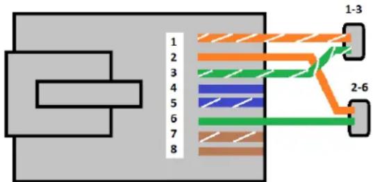
text_image
1 2 3 4 5 6 7 8 1-3 2-6After the _'mer' boots up, _onfirm the st'rtup inform'tion is disp'yed on the 'n'log monitor 'fter 'pproxim'tely 90 se_onds. For ex'mple:
S/N: 1234567
IP Addr: 192.168.250.116
FL#R Systems, #nc.
70 C'stili'n Drive
Golet', CA 93117
=>A
PH: +1 805.964.9797
PH: +1 877.773.3547
(> 'les)
PH: +1 888.747.3547
(>upport)
F": +1 805.685.2711
www.flir.om
—corporate "eadquarters
FLIR >systems, In_
27700 >W P'rkw'y Ave.
Wilsonville, °R 97070
=>A
PH: +1 503.498.3547
F": +1 503.498.3153
s'les@flir._om