CineTension 2 TE110HW2 - Projection screen Elite Screens - Free user manual and instructions
Find the device manual for free CineTension 2 TE110HW2 Elite Screens in PDF.


| Product Type | Tab-tensioned Electric Motorized Projection Screen |
| Brand | Elite Screens |
| Model | CineTension 2 TE110HW2 |
| Screen Diagonal | 110 inches (estimated) |
| Aspect Ratio | 16:9 |
| Viewing Area (W x H) | 96 x 54 inches (approx) |
| Screen Material | Matte White |
| Gain | 1.0 |
| Viewing Angle | 160 degrees |
| Motor Type | Quiet electric motor |
| Voltage | 100V – 220V AC (regional) |
| Power Consumption | 50W (estimated) |
| Control Methods | IR remote, RF remote, 3-way wall switch, 5-12V trigger, wireless 5-12V trigger, IR eye receiver |
| Tension System | Adjustable side tension strings |
| Black Top Drop | Pre-set to maximum; no extra drop in roller |
| Weight | 35 lbs (estimated) |
| Mounting Options | Wall, ceiling, flush mount, enclosed |
| Included Accessories | IR remote, RF remote, 3-way wall switch, 5-12V trigger cable, IR eye receiver, wireless trigger cable, AAA batteries, bubble leveler, mounting hardware |
| Compliance | FCC Class B |
| Warranty | Contact Elite Screens for details |
Frequently Asked Questions - CineTension 2 TE110HW2 Elite Screens
User questions about CineTension 2 TE110HW2 Elite Screens
0 question about this device. Answer the ones you know or ask your own.
Ask a new question about this device
Download the instructions for your Projection screen in PDF format for free! Find your manual CineTension 2 TE110HW2 - Elite Screens and take your electronic device back in hand. On this page are published all the documents necessary for the use of your device. CineTension 2 TE110HW2 by Elite Screens.
USER MANUAL CineTension 2 TE110HW2 Elite Screens
text_image
ELITE SCREENSTab-tensioned Electric Motorized Projection Screen
CineTension 2 Series
User's Guide
Important Safety & Warning Precautions
Make sure to read this user's guide and follow the procedures below.
Caution: The screen's Black Top Drop is already set to its maximum drop distance. There is NO extra Black Top Drop in the roller. Please be aware of this as it will void your warranty with Elite Screens. Unapproved changes or modifications (except for cutting the power cord for hardwire installations) to this unit are prohibited and will void your warranty. For more information, please contact our Technical Support Department at (877) 511-1211 Ext. 604.
- Please retain this user's guide for future reference.
- To avoid damaging the unit, do not use with any unauthorized accessories not recommended by the manufacturer.
- Handle the unit carefully during transportation to avoid any damages.
- To ensure safe and reliable operation, direct connection to a properly grounded power source is advised.
- The power outlet supplying power to the unit should be close to the unit and easily accessible.
- Do not install the unit on uneven, inclined surfaces;
- Do not install in damp places to avoid an electric shock or short circuit.
- Do not place any heavy objects over the power cord.
- Position the power cord properly to avoid creating a trip obstacle.
- To avoid an electrical shock or fire, due to a loose contact or short circuit, do not overload the power cord.
- The internal & external parts of this unit are not end user serviceable. Do not attempt to disassemble this unit by yourself. No one except authorized technicians can open and make repairs to this unit.
• Make sure the power source that this unit is connected to has a continuous power flow. - If there is need to use an extension cord, make sure the cord has an equal rating as the appliance to avoid over heat.
- Do not handle the power plug when your hands are wet or your feet are in contact with water.
- Properly dispose of this equipment according to the environmental regulations in your area when product is no longer of service.
Do not use this unit under the following circumstances.
- Disconnect the power cord under the conditions of heavy rain, wind thunder or lightning.
- Avoid direct sun light, rain shower and moisture.
- Keep away from fire sources and high temperature to prevent this device from overheating.
- Cut off the power supply first before transportation or maintenance.
- To avoid possible injury and/or an electric shock, do not attempt to use this screen if there is obvious damage or if there are any evident broken parts.
Installation Warning
The instructions provided in this user's guide are for reference only. Please consult a professional installation company for further installation and safety advice. The installer must insure that proper mounting hardware is used to provide adequate strength suitable for the installation. Elite Screens is not liable for any faulty installations. For limit adjustment instructions, please contact our Technical Support Department at (877) 511-1211 Ext. 604
The Screen's Top Black Drop is already set to its maximum drop distance. There is NO extra top black drop in the roller. Please be aware of this as it will void the limitation of your warranty.
Individual modifications to this product are prohibited and will void the warranty with the manufacturer. Please contact Elite Screens Customer Service for any questions.
NOTE:
This equipment has been tested and found to comply with the limits for a Class B digital device, pursuant to Part 15 of the FCC Rules.
These limits are designed to provide reasonable protection against harmful interference in a residential installation. This equipment generates and can radiate radio frequency energy and, if not installed and used in accordance with the instructions, may cause harmful interference to radio communications.
However, there is no guarantee that the interference will not occur on a particular installation. If this equipment causes harmful interference to radio or television reception, which can be determined by turning the equipment off and on, the user is encouraged to try to correct the interference by one or more of the following measures.
√ Reorient or relocate the receiving antenna of the device which may be casing the interference.
√ Increase the separation between the screen and the device's receiver.
√ Connect the equipment into a different power outlet other than the device.
Pre-Installation
- Carefully unpack the screen.
- Always handle the screen in a leveled position on a clean surface.
- In order to protect the screen from exposure to stains, keep the screen out of contact with foreign particles such as dust, sawdust, and/or liquids.
NOTE
Regardless of the mounting method, the screen should be securely supported so that the vibration or pulling on the viewing surface will not cause the casing to become loose or fall. The installer must insure the fasteners that are used are of adequate strength and suitable for the installation location.
| CineTension 2 Series| Controls and Accessories | ||||
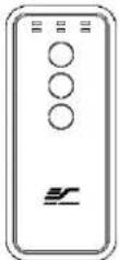
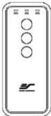
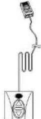
| A. IR Remote | B. RF Remote C. Wall switch control box | D. 5-12 volt trigger cable | ||
 |  |  |  | |
| E. IR extended “eye” receiver | F. Wireless 5-12v (3.5 mm) mono trigger cable | G. AAA batteries | H. Bubble leveler | |
| [YICA] | [HSWX] | 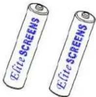 | 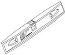 | |
Screen operation
Electric Current: Depending upon region, your Elite Screen will operate on 100v, 110v, or 220v voltage.
1. After ensuring the power outlet & screen are compatible (voltage), plug the power cord into the power outlet.
2. Once the screen has power, you'll be able to control it using any of the 6 methods described below.
6 ways to control your CineTension 2
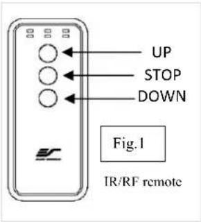
- IR remote control (Item A, Fig 1): The Infrared functions by direct line of sight contact with a beam range of 30 feet. Aim the IR remote at the circular window located on the left side of the screen
- IR "Eye" Receiver (Item E, Fig 2): The IR "Eye" Receiver plugs directly into the screen's RJ-45 input to present a low profile line-of-sight control option for your IR remote control even in a recessed ceiling installation.
- RF Remote Control (Item B): The radio waves eliminate the need for a direct line of sight with a range of 100 feet.
- 3-Way Wall Switch (Item C, Fig 3): The 3-way wall switch is a wall mount control box with an up/stop/down button and plugs directly into the screen's RJ-45 input.
text_image
UP STOP DOWN Fig.1 IR/RF remote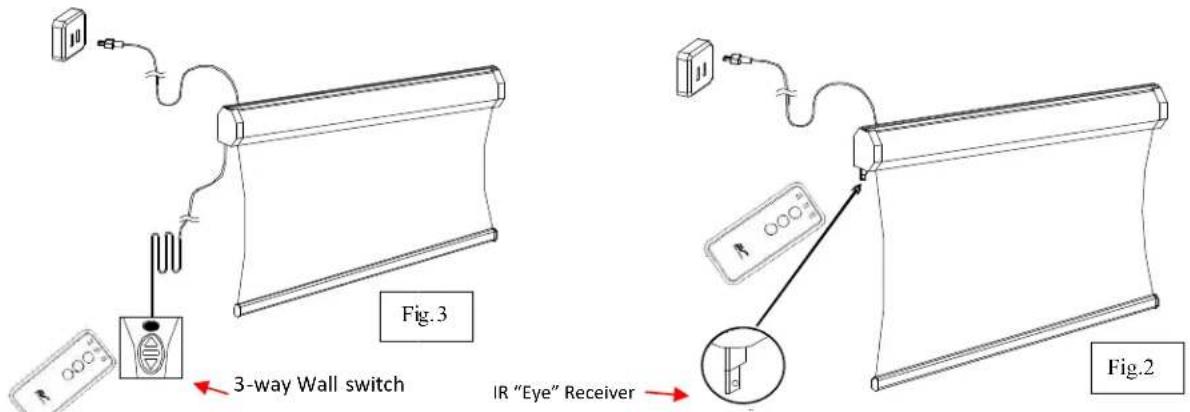
text_image
3-way Wall switch IR "Eye" Receiver Fig.2Rev.062916-DR
www.elitescreens.com
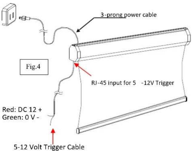
- 5-12 volt trigger (Item D, Fig 4): The built-in 5-12V trigger input allows your screen to synchronize its drop & rise with the projector's power cycle. The screen deploys when the projector powers up and will retract when the projector powers down. The 5-12 volt RJ45 cable connects to your projector's trigger output via a separate cable that may or may not be provided by the manufacturer of the projector. The trigger feature will not work without an output cable from the projector, but it can be tested by connecting the Red (+) and Green (-) cable to a 9-volt battery.
text_image
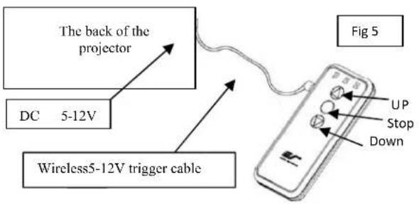
3-prong power cable RJ-45 input for 5 -12V Trigger Fig.4 Red: DC 12 + Green: 0 V - 5-12 Volt Trigger Cable- Wireless 5-12 volt trigger (Item F, Fig 5): The RF remote control serves as a dual purpose, independently as a handheld remote control, or in conjunction with the Wireless 5-12 volt trigger cable. The radio frequency technology can be programmed to send a wireless signal to synchronize it drop/rise with the projector's power cycle.
text_image
The back of the projector DC 5-12V Wireless5-12V trigger cable Fig 5 UP Stop DownHere's how to set up your Wireless 5-12 volt trigger | Synchronization Instructions
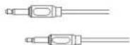
Step1: Connect one end of the 3.5 mm wireless 5-12 volt trigger cable to the RF remote.
Step 2: Connect the other 3.5 mm end of the wireless 5-12 volt trigger cable to your projector
Step 3: Make sure to unplug your screen from the power outlet
Step 4: Hold the UP button on your RF remote
Step 5: While holding the UP button, plug the screen back to the power outlet
Step 6: Wait 5 seconds and then release the UP button
Step 7: Your 5-12V wireless trigger should now be activated with your screen and ready to be used and able to control your screen with your projector's power cycle
Repeat the steps again if not successful.
(Please be aware, the projector on/off cycle may take longer to fully activate. It usually takes around 20-30 seconds for full off and on cycle each time)
Hardware Parts List for CineTension 2 Series
Please make sure all parts listed below are included before proceeding with the installation.
| A. M12 Dry-wall anchor x 4 or 6 | B. Bolt x 2 or 3 | C. Masonry Screw x 4 or 6 | C. Extruded Hanging Bracket x 2 or 3 |
| 120”& above x 3 brackets |
Rev.062916-DR
www.elitescreens.com
Installation Instruction
Wall Screws included with this product are complementary and may not be adequate for all mounting surfaces. Consult with a professional installer or hardware store for proper mounting screws and anchors. Please consult a professional installer. Elite Screens is not liable for any faulty installations.
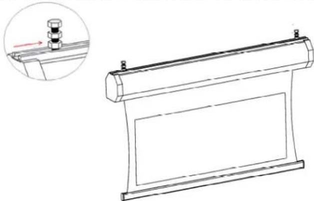
- Insert each Bolt (B) through the right & left slide channel located on the top of the screen's case.
natural_image
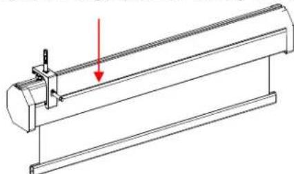
Technical line drawing of a scroll or roller assembly with a magnified inset showing a small component (no text or symbols present)- Slide the Extruded Hanging Bracket (D) through the rail located below the slide channel until it meets with the top of the Bolt (B) and slightly secure the lug-nuts located on the top & bottom of the bolt to attach the bracket.
natural_image
Technical line drawing of a mechanical assembly with a red arrow indicating a component (no text or symbols present)- Mark the installation location to drill your hole. Insert the proper screw and secure the bolts to the bracket.
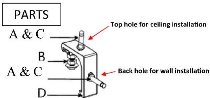
text_image
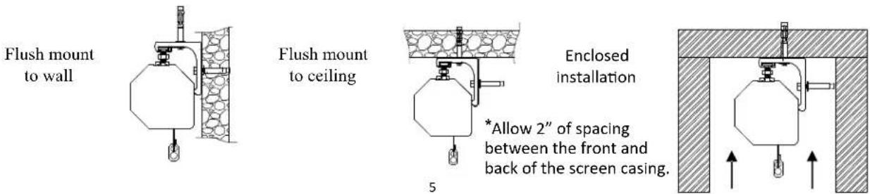
PARTS A & C B A & C D Top hole for ceiling installation Back hole for wall installation- Example of the CineTension 2 installed to a wall, ceiling and enclosed.
text_image
Flush mount to wall Flush mount to ceiling Enclosed installation *Allow 2" of spacing between the front and back of the screen casing. 5Rev.062916-DR www.elitescreens.com
Adjusting the Tension String
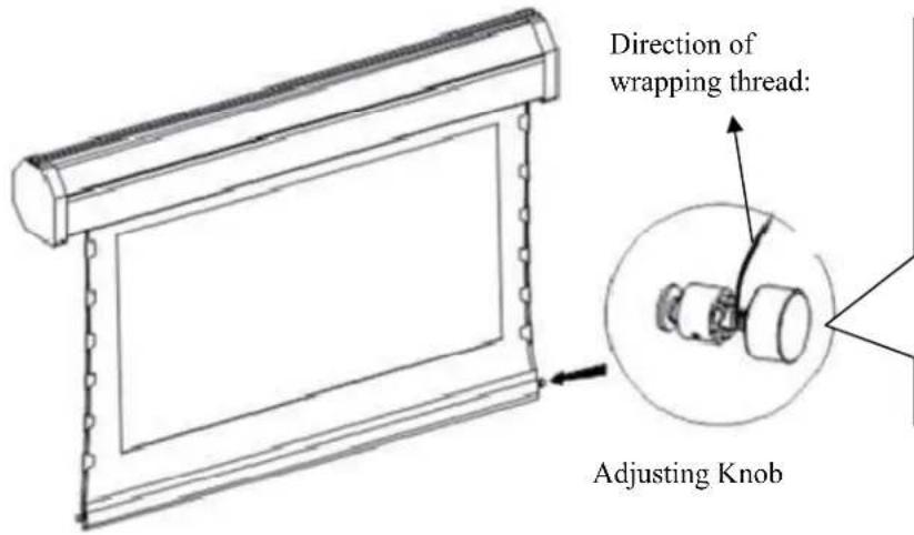
There are adjustment knobs located at the end of the weight bar of the screen. If for any reason the tension string(s) is loose, you can re-tension it by adjusting the tension string(s) knobs. The tension should be equally balanced in order to provide a flat, uniform projection surface.
text_image
Direction of wrapping thread: Adjusting KnobAdjustment method: Pull out the adjusting knob and rotate it to tighten or loosen tension string. The direction to tighten/loosen the string will depend on the direction of the wrapping thread.
Attention: The string and screen will lose all tension if the string is loosened to its maximum. To reverse this, simply turn the knob in the opposite direction.
Attention: The screen's tension has been preset to achieve its best performance. The aforementioned adjustments are typically not required. Prior to making adjustments, please contact Elite Screens for assistance to avoid damaging the screen and voiding your warranty.
For warranty information, please visit www.elitescreens.com/warranty
For local Elite Screens contact or Technical Support, please visit www.elitescreens.com