
Legion Y720T - Desktop computer LENOVO - Free user manual and instructions
Find the device manual for free Legion Y720T LENOVO in PDF.


User questions about Legion Y720T LENOVO
0 question about this device. Answer the ones you know or ask your own.
Ask a new question about this device
Download the instructions for your Desktop computer in PDF format for free! Find your manual Legion Y720T - LENOVO and take your electronic device back in hand. On this page are published all the documents necessary for the use of your device. Legion Y720T by LENOVO.
USER MANUAL Legion Y720T LENOVO
Lenovo Legion Y720T Hardware Maintenance Manual
Machine Types: 90H9 [Lenovo Legion Y720T-34ASU/Energy Star]
Lenovo Legion Y720T Hardware Maintenance Manual
Machine Types: 90H9 [Lenovo Legion Y720T-34ASU/Energy Star]
First Edition (July 2017)15th
© Copyright Lenovo 2017.
LIMITED AND RESTRICTED RIGHTS NOTICE: If data or software are delivered pursuant a General Services Administration "GSA" contract, use, reproduction, or disclosure is subject to restrictions set forth in Contract No. GS-35F-05925
Contents
Chapter 1. About this manual ..... 1
Important Safety Information ..... 1
Chapter 2. Safety information .... 3
General safety 3
Electrical safety 4
Safety inspection guide 5
Handling electrostatic discharge-sensitive devices ..... 6
Grounding requirements. 7
Safety notices....7
Chapter 3. General information....11
Specifications....11
Chapter 4. General Checkout ..... 13
Chapter 5. Using the Setup Utility ..... 15
Starting the Lenovo BIOS Setup Utility program ..... 15
Viewing and changing settings. . . . . . . . . . . . . . . . . . . 15
Using passwords....15
Enabling or disabling a device ..... 18
Selecting a startup device ..... 19
Exiting the Lenovo BIOS Setup Utility program .....20
Chapter 6. Symptom-to-FRU Index ..... 23
Hard disk drive boot error ..... 23
Power Supply Problems....23
Additional Service Information ..... 24
POST error codes ..... 24
Undetermined problems....25
Chapter 7. Locations ..... 27
Identifying internal components ..... 27
Identifying parts on the system board 30
Chapter 8. Replacing hardware. . . . . . . . . . . . . . . . . . . . . . . . . 33
General information....33
Cleaning rear dust screen 34
Replacing the keyboard and mouse . . . . . . . . . . . . . . . . . 35
Removing the computer cover . . . . . . . . . . . . . . . . . . . . 35
Removing the computer cover ii . . . . . . . . . . . . . . . . . . . 36
Removing the front bezel . . . . . . . . . . . . . . . . . . . . . . . 37
Cleaning front dust screen . . . . . . . . . . . . . . . . . . . . . . . 38
Replacing a memory module ..... 39
Replacing a hard disk drive . . . . . . . . . . . . . . . . . . . . . . 40
Replacing an optical drive ..... 41
Replacing the microprocessor fan assembly ..... 42
Replacing the rear system fan . . . . . . . . . . . . . . . . . . . . 43
Replacing a front fan . . . . . . . . . . . . . . . . . . . . . . . . . 44
Replacing the Power supply . . . . . . . . . . . . . . . . . . . 46
Replacing the Wi-Fi card. 47
Removing the top cover . . . . . . . . . . . . . . . . . . . . . . . 48
Replacing a graphics card . . . . . . . . . . . . . . . . . . . . . . . . 50
Replacing the CPU . . . . . . . . . . . . . . . . . . . . . . . . . . . . . . 51
Replacing the motherboard. 55
FRU lists 56
Chapter 9. General information. . . . . . . . . . . . . . . . . . . . . . . . . . . . . . . . . . . . . . . . . . . . . . 63
Additional Service Information . . . . . . . . . . . . . . . . . . . . 63
Chapter 1. About this manual
This manual contains service and reference information for Lenovo Legion Y720T desktop computers listed on the cover. It is intended only for trained servicers who are familiar with Lenovo computer products.
Before servicing a Lenovo product, be sure to read the Safety Information.
The description of the TV card in this manual is only used for the machines which have the TV card. It is invalid for those machines which do not have TV card.
Important Safety Information
Important: System requirement warning terms for Y900
Your thermal equipment MUST be consistent with your own clock frequency and/or voltage settings.
Important: Lenovo's warranty warning terms for Y900
Altering the default setting of any item in this sub-menu may: (i) reduce system stability and useful life of the system, processor, and other system components; (ii) cause the processor and other system components to fail; (iii) cause reductions in system performance; (iv) cause additional heat or other damage; and (v) affect system data integrity.
Lenovo and Intel have not tested, and do not warranty, the operation of the processor beyond its specifications. Lenovo and Intel have not tested, and do not warranty, the operation of other system components beyond their industry standard specifications.
Lenovo and Intel assume no responsibility that the processor and other system components, including if used with altered clock frequencies, voltages, and/or any other operation parameters will be fit for any particular purpose.
Be sure to read all caution and danger statements in this book before performing any of the instructions.
Chapter 2. Safety information
This chapter contains the safety information that you need to be familiar with before servicing a computer.
General safety
Follow these rules to ensure general safety:
- Observe good housekeeping in the area of the machines during and after maintenance.
-
When lifting any heavy object:
-
Ensure you can stand safely without slipping.
- Distribute the weight of the object equally between your feet.
- Use a slow lifting force. Never move suddenly or twist when you attempt to lift.
- Lift by standing or by pushing up with your leg muscles; this action removes the strain from the muscles in your back.
Do not attempt to lift any objects that weigh more than 16 kg (35 lb) or objects that you think are too heavy for you.
- Do not perform any action that causes hazards to the customer, or that makes the equipment unsafe.
- Before you start the machine, ensure that other service representatives and the customer's personnel are not in a hazardous position.
- Place removed covers and other parts in a safe place, away from all personnel, while you are servicing the machine.
- Keep your tool case away from walk areas so that other people will not trip over it.
- Do not wear loose clothing that can be trapped in the moving parts of a machine. Ensure that your sleeves are fastened or rolled up above your elbows. If your hair is long, fasten it.
- Insert the ends of your necktie or scarf inside clothing or fasten it with a nonconductive clip, approximately 8 centimeters (3 inches) from the end.
- Do not wear jewelry, chains, metal-frame eyeglasses, or metal fasteners for your clothing.
Remember: Metal objects are good electrical conductors.
- Wear safety glasses when you are: hammering, drilling soldering, cutting wire, attaching springs, using solvents, or working in any other conditions that might be hazardous to your eyes.
- After service, reinstall all safety shields, guards, labels, and ground wires. Replace any safety device that is worn or defective.
- Reinstall all covers correctly before returning the machine to the customer.
Electrical safety

CAUTION:
Electrical current from power, telephone, and communication cables can be hazardous. To avoid personal injury or equipment damage, disconnect the attached power cords, telecommunication systems, networks, and modems before you open the computer covers, unless instructed otherwise in the installation and configuration procedures.
Observe the following rules when working on electrical equipment.
Important: Use only approved tools and test equipment. Some hand tools have handles covered with a soft material that does not insulate you when working with live electrical currents.
Many customers have, near their equipment, rubber floor mats that contain small conductive fibers to decrease electrostatic discharges. Do not use this type of mat to protect yourself from electrical shock.
- Find the room emergency power-off (EPO) switch, disconnecting switch, or electrical outlet. If an electrical accident occurs, you can then operate the switch or unplug the power cord quickly.
- Do not work alone under hazardous conditions or near equipment that has hazardous voltages.
-
Disconnect all power before:
-
Performing a mechanical inspection
- Working near power supplies
- Removing or installing Field Replaceable Units (FRUs)
- Before you start to work on the machine, unplug the power cord. If you cannot unplug it, ask the customer to power-off the wall box that supplies power to the machine and to lock the wall box in the off position.
- If you need to work on a machine that has exposed electrical circuits, observe the following precautions:
- Ensure that another person, familiar with the power-off controls, is near you.
Remember: Another person must be there to switch off the power, if necessary.
- Use only one hand when working with powered-on electrical equipment; keep the other hand in your pocket or behind your back.
Remember: There must be a complete circuit to cause electrical shock. By observing the above rule, you may prevent a current from passing through your body.
- When using a tester, set the controls correctly and use the approved probe leads and accessories for that tester.
- Stand on suitable rubber mats (obtained locally, if necessary) to insulate you from grounds such as metal floor strips and machine frames.
Observe the special safety precautions when you work with very high voltages; these instructions are in the safety sections of maintenance information. Use extreme care when measuring high voltages.
- Regularly inspect and maintain your electrical hand tools for safe operational condition.
- Do not use worn or broken tools and testers.
- Never assume that power has been disconnected from a circuit. First, check that it has been powered-off.
- Always look carefully for possible hazards in your work area. Examples of these hazards are moist floors, nongrounded power extension cables, power surges, and missing safety grounds.
- Do not touch live electrical circuits with the reflective surface of a plastic dental mirror. The surface is conductive; such touching can cause personal injury and machine damage.
- Do not service the following parts with the power on when they are removed from their normal operating places in a machine:
- Power supply units
- Pumps
- Blowers and fans
- Motor generators
and similar units. (This practice ensures correct grounding of the units.)
- If an electrical accident occurs:
- Use caution; do not become a victim yourself.
- Switch off power.
- Send another person to get medical aid.
Safety inspection guide
The intent of this inspection guide is to assist you in identifying potentially unsafe conditions on these products. Each machine, as it was designed and built, had
required safety items installed to protect users and service personnel from injury. This guide addresses only those items. However, good judgment should be used to identify potential safety hazards due to attachment of features or options not covered by this inspection guide.
If any unsafe conditions are present, you must determine how serious the apparent hazard could be and whether you can continue without first correcting the problem.
Consider these conditions and the safety hazards they present:
- Electrical hazards, especially primary power (primary voltage on the frame can cause serious or fatal electrical shock).
- Explosive hazards, such as a damaged CRT face or bulging capacitor
- Mechanical hazards, such as loose or missing hardware
The guide consists of a series of steps presented in a checklist. Begin the checks with the power off, and the power cord disconnected.
Checklist:
- Check exterior covers for damage (loose, broken, or sharp edges).
- Power-off the computer. Disconnect the power cord.
-
Check the power cord for:
a. A third-wire ground connector in good condition. Use a meter to measure third-wire ground continuity for 0.1 ohm or less between the external ground pin and frame ground.
b. The power cord should be the appropriate type as specified in the parts listings.
c. Insulation must not be frayed or worn. -
Remove the cover.
-
Check for any obvious alterations. Use good judgment as to the safety of any alterations.
-
Check inside the unit for any obvious unsafe conditions, such as metal filings, contamination, water or other liquids, or signs of fire or smoke damage.
-
Check for worn, frayed, or pinched cables.
-
Check that the power-supply cover fasteners (screws or rivets) have not been removed or tampered with.
Handling electrostatic discharge-sensitive devices
Any computer part containing transistors or integrated circuits (ICs) should be considered sensitive to electrostatic discharge (ESD). ESD damage can occur when there is a difference in charge between objects. Protect against ESD damage by equalizing the charge so that the machine, the part, the work mat, and the person handling the part are all at the same charge.
Notes:
-
Use product-specific ESD procedures when they exceed the requirements noted here.
-
Make sure that the ESD protective devices you use have been certified (ISO 9000) as fully effective.
When handling ESD-sensitive parts:
- Keep the parts in protective packages until they are inserted into the product.
- Avoid contact with other people while handling the part.
- Wear a grounded wrist strap against your skin to eliminate static on your body.
- Prevent the part from touching your clothing. Most clothing is insulative and retains a charge even when you are wearing a wrist strap.
- Use the black side of a grounded work mat to provide a static-free work surface. The mat is especially useful when handling ESD-sensitive devices.
- Select a grounding system, such as those listed below, to provide protection that meets the specific service requirement.
Note: The use of a grounding system is desirable but not required to protect against ESD damage.
- Attach the ESD ground clip to any frame ground, ground braid, or green-wire ground.
- Use an ESD common ground or reference point when working on a double-insulated or battery-operated system. You can use coax or connector-outside shells on these systems.
- Use the round ground-prong of the ac plug on ac-operated computers.
Grounding requirements
Electrical grounding of the computer is required for operator safety and correct system function. Proper grounding of the electrical outlet can be verified by a certified electrician.
Safety notices
The caution and danger safety notices in this section are provided in the the language of English.

DANGER
Electrical current from power, telephone and communication cables is hazardous.
To avoid a shock hazard:
- Do not connect or disconnect any cables or perform installation, maintenance, or reconfiguration of this product during an electrical storm.
- Connect all power cords to a properly wired and grounded electrical outlet.
- Connect to properly wired outlets any equipment that will be attached to this product.
- When possible, use one hand only to connect or disconnect signal cables.
- Never turn on any equipment when there is evidence of fire, water, or structural damage.
- Disconnect the attached power cords, telecommunications systems, networks, and modems before you open the device covers, unless instructed otherwise in the installation and configuration procedures.
- Connect and disconnect cables as described in the following table when installing, moving, or opening covers on this product or attached devices.
| To Connect To Disconnect | |
| 1. Turn everything OFF.2. First, attach all cables to devices.3. Attach signal cables to connectors.4. Attach power cords to outlet.5. Turn device ON. | 1. Turn everything OFF.2. First, remove power cords from outlet.3. Remove signal cables from connectors.4. Remove all cables from devices. |

CAUTION:
When replacing the lithium battery, use only Part Number 45C1566 or an equivalent type battery recommended by the manufacturer. If your system has a module containing a lithium battery, replace it only with the same module type made by the same manufacturer. The battery contains lithium and can explode if not properly used, handled, or disposed of.
Do not:
- Throw or immerse into water
• Heat to more than 100°C (212°F)
• Repair or disassemble
Dispose of the battery as required by local ordinances or regulations.

CAUTION:
When laser products (such as CD-ROMs, DVD-ROM drives, fiber optic devices, or transmitters) are installed, note the following:
- Do not remove the covers. Removing the covers of the laser product could result in exposure to hazardous laser radiation. There are no serviceable parts inside the device.
- Use of controls or adjustments or performance of procedures other than those specified herein might result in hazardous radiation exposure.


DANGER
Some laser products contain an embedded Class 3A or Class 3B laser diode. Note the following: Laser radiation when open. Do not stare into the beam, do not view directly with optical instruments, and avoid direct exposure to the beam.

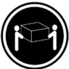 |  |  |
| ≥18 kg(37 lbs) ≥32 kg | (70.5 lbs) ≥55 kg(121.2 lbs) |
CAUTION:
Use safe practices when lifting.

CAUTION:
The power control button on the device and the power switch on the power supply do not turn off the electrical current supplied to the device. The device also might have more than one power cord. To remove all electrical current from the device, ensure that all power cords are disconnected from the power source.

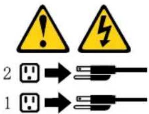
text_image
2 1
CAUTION:
Do not place any object weighing more than 82 kg (180 lbs.) on top of rack-mounted devices.
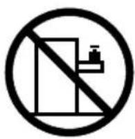
text_image
Prohibition sign with no text, featuring a crossed-out building and a water bottle symbol inside a circle.Chapter 3. General information
This chapter provides general information that applies to all machine types supported by this publication.
Specifications
This section lists the physical specifications for your computer.
This section lists the physical specifications for your computer.
Type Lenovo Legion Y720T
This section lists the physical specifications.
Environment
Air temperature:
Operating: 10° to 35°C
Transit: -20° to 55°C
Humidity:
Operating: 35% to 80%
Transit: 20% to 90% (40°C)
Altitude: 86KPa to 106KPa
Electrical input:
Input voltage: 90V-264V(AC)
Input frequency: 47Hz-63Hz
Chapter 4. General Checkout
Attention: The drives in the computer you are servicing might have been rearranged or the drive startup sequence changed. Be extremely careful during write operations such as copying, saving, or formatting. Data or programs can be overwritten if you select an incorrect drive.
General error messages appear if a problem or conflict is found by an application program, the operating system, or both. For an explanation of these messages, refer to the information supplied with that software package.
Use the following procedure to help determine the cause of the problem:
- Power-off the computer and all external devices.
- Check all cables and power cords.
- Set all display controls to the middle position.
- Power-on all external devices.
-
Power-on the computer.
-
Look for displayed error codes
-
Look for readable instructions or a main menu on the display.
If you did not receive the correct response, proceed to step 6. If you do receive the correct response, proceed to step 7. -
Look at the following conditions and follow the instructions:
-
If the computer displays a POST error, go to "POST error codes".
-
If the computer hangs and no error is displayed, continue at step 7.
-
If the test stops and you cannot continue, replace the last device tested.
Chapter 5. Using the Setup Utility
The Setup Utility program is used to view and change the configuration settings of your computer, regardless of which operating system you are using. However, the operating-system settings might override any similar settings in the Setup Utility program.
Starting the Lenovo BIOS Setup Utility program
To start the Lenovo BIOS Setup Utility program, do the following:
-
If your computer is already on when you start this procedure, shut down the operating system and turn off the computer.
-
Press and hold the F1 key then turn on the computer. When the Lenovo BIOS Setup Utility program is displayed, release the F1 key.
Note:
If a Power-On Password or an Administrator Password has been set, the Setup Utility program menu is not displayed until you type your password. For more information, see “Using passwords.”
Viewing and changing settings
System configuration options are listed in the Lenovo BIOS Setup Utility program menu. To view or change settings, see “Starting the Setup Utility program.”
You must use the keyboard when using the Lenovo BIOS Setup Utility menu. The keys used to perform various tasks are displayed on the bottom of each screen.
Using passwords
You can use the Lenovo BIOS Setup Utility program to set passwords to prevent unauthorized persons from gaining access to your computer and data. See "Starting the Setup Utility program." The following types of passwords are available:
- Set Administrator Password
- Set Power-On Password
You do not have to set any passwords to use your computer. However, if you decide to set passwords, read the following sections.
Password considerations
A password can be any combination of letters and numbers up to 16 character (a-z, and 0-9). For security reasons, it is a good idea to use a strong password that cannot be easily compromised. We suggest that passwords should follow these rules:
• Strong passwords contain 7-16 characters, combine letters and numbers.
- Do not use your name or your user name.
- Do not use a common word or a common name.
- Be significantly different from your previous password.
Attention: Administrator and Power-On passwords are not case sensitive
Administrator Password
Setting an Administrator Password deters unauthorized persons from changing configuration settings. You might want to set an Administrator Password if you are responsible for maintaining the settings of several computers.
After you set an Administrator Password, a password prompt is displayed every time you access the Lenovo BIOS Setup Utility program.
If both the Administrator and Power-On Password are set, you can type either password. However, you must use your Administrator Password to change any configuration settings.
Setting, changing, or deleting an Administrator password
To set an Administrator Password, do the following:
Note: A password can be any combination of letters and numbers up to 16 character (a-z, and 0-9). For more information, see “Password considerations” on page 13.
- Start the Lenovo BIOS Setup Utility program (see "Starting the Lenovo BIOS Setup Utility program" on page 13).
- From the Security menu, select Set Administrator Password and press the Enter key.
- The password dialog box will be displayed. Type the password then press the Enter key.
- Re-type the password to confirm, then press the Enter key. If you type the password correctly, the password will be installed.
To change an Administrator Password, do the following:
-
Start the Lenovo BIOS Setup Utility program (see "Starting the Lenovo BIOS Setup Utility program" on page 13).
-
From the Security menu, select Set Administrator Password and press the Enter key.
-
The password dialog box will be displayed. Type the current password then press Enter key.
-
Type the new password, then press Enter key. Re-type the password to confirm the new password, if you type the new password correctly, the new password will be installed. A Setup Notice will display that changes have been saved.
To delete a previously set Administrator Password, do the following :
-
From the Security menu, select Set Administrator Password and press the Enter key.
-
The password dialog box will be displayed. Type the current password and press the Enter key.
-
To delete an Administrator Password, Enter blank fields for each new password line item. A setup notice will display that changes have been saved.
-
Return to the Lenovo BIOS Setup Utility program menu and select the Exit option.
-
Select Save changes and Exit from the menu.
Power-On Password
When a Power-On Password is set, you cannot start the Lenovo BIOS Setup Utility program until a valid password is typed from the keyboard.
Setting, changing, or deleting a Power-On Password
Note: A password can be any combination of letters and numbers up to 16 character (a-z, and 0-9).
To set a Power-On Password, do the following:
-
Start the Lenovo BIOS Setup Utility program (See "Starting the Lenovo BIOS Setup Utility program" on page 13.)
-
From the Security menu, select Set Power-On Password and press the Enter key.
-
The password dialog box will be displayed. Type the password, and press the Enter key.
-
Re-type the password to confirm, if you type the password correctly, the password will be installed.
To change a Power-On Password, do the following:
- Start the Lenovo BIOS Setup Utility program (See "Starting the Lenovo BIOS Setup Utility program" on page 13.)
- From the Security menu, select Set Power-On Password and press the Enter key.
- The password dialog box will be displayed. Type the current password then press the Enter key.
- Type the new password, then press the Enter key. Re-type the password to confirm the new password, if you type the new password correctly, the new password will be installed. A setup notice will display that changes have been saved.
To delete a previously set Power-On Password, do the following :
- From the Security menu, select Set Power-On Password and press the Enter key.
- The password dialog box will be displayed. Type the current password and press the Enter key.
- To delete the Power-On Password, Enter blank fields for each new password line item. A setup notice will display that changes have been saved.
- Return to the Lenovo BIOS Setup Utility program menu and select the Exit option.
- Select Save changes and Exit from the menu.
Enabling or disabling a device
| The Devices options is used to enable or disable user access to the following devices: | |
| USB Functions Select whether to enable or | disable USB(Universal Serial Bus) functions. If the functions are disabled, no USB devices can be used. |
| ATA Drive Setup Select IDE or ACHI mode. | Device driver support is required for ACHI mode.Depending on how the hard disk image was installed, changing this setting may prevent the system from booting. |
| Onboard Audio Controller Select whether to enable or disable the Onboard Audio Controller, when feature is set to Disabled all devices connected to the audio connectors (e.g. a headphone or a microphone) are disabled and can’t be used. | |
| Onboard Ethernet Controller or Boot Agent | Select whether to enable or disable Onboard Ethernet Controller, or select whether to enable or disable load onboard PXE (Preboot Execution Environment), or SMC (Secure Managed Client). This feature will allow the computer to boot from a server image. |
To enable or disable a device, do the following:
- Start the Setup Utility program (see "Starting the Setup Utility program" on page 13).
- From the Setup Utility program menu, select Devices.
- Select:
USB Setup press the Enter key, and then select USB Functions.
ATA Device Setup press the Enter key. Select Configure SATA as, press the Enter key and then select SATA mode.
Audio Setup press the Enter key, and then select Onboard Audio Controller.
Network Setup press the Enter key, then select Onboard Ethernet Support or Boot Agent.
- Select Disabled or Enabled and press the Enter key.
- Return to the Lenovo BIOS Setup Utility program menu and select the Exit option.
- Select Save changes and Exit from the menu.
Note:
If you do not want to save the settings, select Discard changes and Exit from the menu.
Selecting a startup device
If your computer does not boot from a device such as the CD/DVD-ROM drive disk or hard disk as expected, follow one of the procedures below.
Selecting a temporary startup device
Use this procedure to startup from any boot device.
Note: Not all CDs, DVDs or hard disk drives are bootable.
- Turn off your computer.
- Press and hold the F12 key then turn on the computer. When the Startup Device Menu appears, release the F12 key.
Note: If the Startup Device Menu does not display using these steps, repeatedly press and release the F12 key rather than keeping it pressed when turning on the computer.
- Use ↑ and ↓ arrows to select the desired startup device from the Startup Device Menu and press the Enter key to begin.
Note: Selecting a startup device from the Startup Device Menu does not permanently change the startup sequence.
Selecting or changing the startup device sequence
To view or permanently change the configured startup device sequence, do the following:
- Start the Lenovo BIOS Setup Utility program (see "Starting the Lenovo BIOS Setup Utility program" on page 13).
- From the Lenovo BIOS Setup Utility program main menu, select the Startup option.
- Press the Enter key, and select the devices for the Primary Boot Sequence. Read the information displayed on the right side of the screen.
- Use ↑ and ↓ arrows to select a device. Use the <+> or <-> keys to move a device up or down. Use the
key to exclude the device from or include the device in the boot sequence. - Return to the Lenovo BIOS Setup Utility program menu and select the Exit option.
- Select Save changes and Exit from the menu.
Notes:
a. If you do not want to save the settings, select Discard changes and Exit from the menu.
b. If you have changed these settings and want to return to the default settings, select Load Optimal Defaults from the menu.
Exiting the Lenovo BIOS Setup Utility program
After you finish viewing or changing settings, press the Esc key to return to the Lenovo BIOS Setup Utility program main menu. You might have to press the Esc key several times. Do one of the following:
- If you want to save the new settings, select Save changes and Exit from the menu. When the Save & reset window shows, select the Yes button, and then press the Enter key to exit the Lenovo BIOS Setup Utility program.
- If you do not want to save the settings, select Discard changes and Exit from the menu. When the Reset Without Saving window shows, select the Yes button, and then press the Enter key to exit the Setup Utility program.
Chapter 6. Symptom-to-FRU Index
The Symptom-to-FRU index lists error symptoms and possible causes. The most likely cause is listed first. Always begin with Chapter 4, “General Checkout,” on page 11. This index can also be used to help you decide which FRUs to have available when servicing a computer. If you are unable to correct the problem using this index, go to “Undetermined problems” on page 20.
Notes:
- If you have both an error message and an incorrect audio response, diagnose the error message first.
- If you cannot run the diagnostic tests or you get a diagnostic error code when running a test but did receive a POST error message, diagnose the POST error message first.
- If you did not receive any error message look for a description of your error symptoms in the first part of this index.
Hard disk drive boot error
A hard disk drive boot error can have the following causes.
| Error FRU/Action | |
| The startup drive is not included in the boot sequence in configuration. | Check the configuration and ensure the startup drive is in the boot sequence. |
| No operating system installed on the boot drive. | Install an operating system on the boot drive. |
| The boot sector on the startup drive is corrupted. | The drive must be formatted. Do the following:1. Attempt to back-up the data on the failing hard disk drive.2. Use the operating system to format the hard disk drive. |
| The drive is defective. Replace the hard disk drive. | |
Power Supply Problems
Follow these procedures if you suspect there is a power supply problem.
| Check/Verify FRU/Action | |
| Check that the following are properly installed:• Power Cord• On/Off Switch connector• System Board Power Supply connectors• Microprocessor(s) connection | Reseat connectors |
| Check the power cord. Power Cord | |
| Check the power-on switch. Power-on Switch |
Additional Service Information
This chapter provides additional information that the service representative might find helpful.
Power management
Power management reduces the power consumption of certain components of the computer such as the system power supply, processor, hard disk drives, and some monitors.
Advanced configuration and power interface (ACPI) BIOS
As this computer has an ACPI BIOS system, the operating system is allowed to control the power management features of the computer and the settings for Advanced Power Management (APM) BIOS mode is ignored. Not all operating systems support ACPI BIOS mode.
Automatic Power-On features
The Automatic Power-On features within the Power Management menu allow you to enable and disable features that turn on the computer automatically.
- Wake Up on Alarm: You can specify a date and time at which the computer will be turned on automatically. This can be either a single event, a daily event or a weekly event.
- Wake Up on LAN: This feature allows LAN adapter card to wake the System.
POST error codes
Each time you turn the computer on, it performs a series of tests to check that the system is operating correctly and that certain options are set. This series of tests is called the Power-On Self-Test, or POST. POST does the following:
- Checks some basic system-board operations
- Checks that the memory is working correctly
- Starts video operations
• Verifies that the boot drive is working
| POST Error Message Description/Action | |
| Keyboard error | Cannot initialize the keyboard. Make sure the keyboard is properly connected to the computer and that no keys are held pressed during POST. To purposely configure the computer without a keyboard, select Keyboardless operation in Startup option to Enabled. The BIOS then ignores the missing keyboard during POST. |
| Reboot and Select proper Boot device or Insert Boot Media in selected Boot device | The BIOS was unable to find a suitable boot device. Make sure the boot drive is properly connected to the computer. Make sure you have bootable media in the boot device. |
Undetermined problems
- Power-off the computer.
-
Remove or disconnect the following components (if connected or installed) one at a time.
a. External devices (modem, printer, or mouse)
b. Extended video memory
c. External Cache
d. External Cache RAM
e. Hard disk drive
f. Disk drive -
Power-on the computer to re-test the system.
- Repeat steps 1 through 3 until you find the failing device or component.
If all devices and components have been removed and the problem continues, replace the system board.
Chapter 7. Locations
This section provides illustrations to help locate the various connectors, controls and components of the computer.
Identifying internal components
The following illustration shows the components inside your computer.
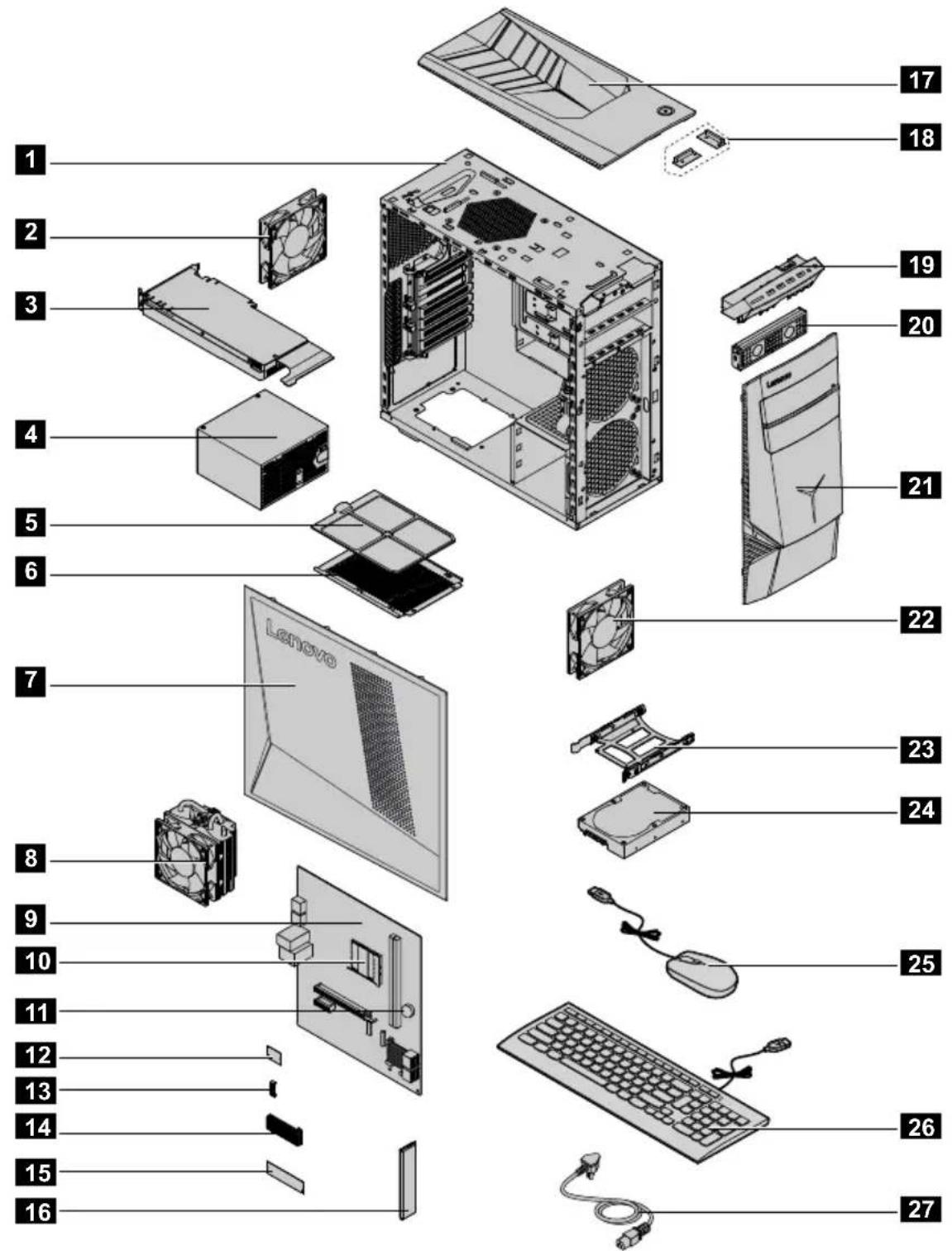
text_image
Exploded view diagram of a Lenovo desktop computer with numbered components for identification| No. Description | Self-service CRU Opt | onal-serviceCRU | |
| 1 | Chassis No No | ||
| 2 | System fan (rear) | No No | |
| 3 | Graphic card | Yes No | |
| 4 | Power supply unit No | No | |
| 5 | Dust filter Yes Yes | ||
| 6 | Dust filter bracket No | No | |
| 7 | Side cover (with Lenovo logo) | Yes Yes | |
| 8 | Micro-processor fan assembly | No No | |
| 9 | Motherboard No No | ||
| 10 | CPU | Yes No | |
| 11 | CR2302 baterry No No | ||
| 12 | Wi-Fi card No No | ||
| 13 | Wi-Fi bracket No No | ||
| 14 | Micro-process heat-sink fin | No No | |
| 15 | SSD Yes Yes | ||
| 16 | Memory module Yes | Yes | |
| 17 | Top cover No No | ||
| 18 | Wi-Fi antenna No No | ||
| 19 | Front I/O module No | No | |
| 20 | Optical drive holder No | No | |
| 21 | Front bezel | Yes Yes | |
| 22 | System fan (front) | No Yes | |
| 23 | Hard disk drive bracket | Yes Yes | |
| 24 | Hard disk drive | Yes Yes | |
| 25 | Mouse | Yes Yes | |
| 26 | Keyboard | Yes Yes | |
| 27 | Power cord | Yes Yes |
Identifying parts on the system board
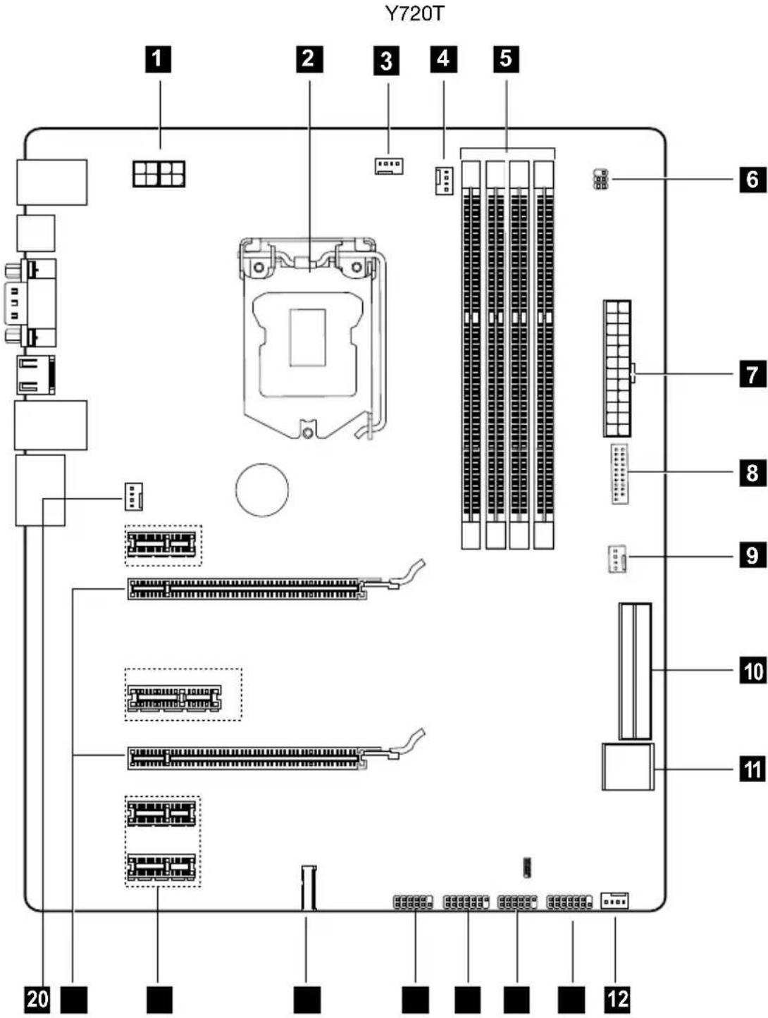
The system board (also known as the “mainboard” or “motherboard”) is the main circuit board in your computer. It provides basic computer functions and supports a variety of devices that are factory-installed or that you can install later.
The following illustrations show the locations of the different parts on the system board.
text_image
Y720T 1 2 3 4 5 6 7 8 9 10 11 12 20| 1 12V power connector | 11 Front USB 3.0 connector |
| 2 Microprocessor | 12 Aux fan 2 |
| 3 Microprocessor fan header 1 | 13 Front panel connector |
| 4 Microprocessor fan header 2 | 14 Front USB 2.0 connector Power fan header |
| 5 Memory slots (4) | 15 Front USB, card reader connector |
| 6 Front LED header | 16 LPC debug |
| 7 Power connector | 17 Mini PCI-E slot |
| 8 Front USB 3.0 slot | 18 PCI express X 1 adapter slots (5) |
| 9 Aux fan 1 | 19 PCI express X 16 adapter slot |
| 10 SATA connectors (4) | 20 System fan header |
Chapter 8. Replacing hardware
Attention: Do not remove the computer cover or attempt any repair before reading the “Important safety information” in the Safety and Warranty Guide that was included with your computer. To obtain copies of the Safety and Warranty Guide, go to the Support Web site at: http://consumersupport.lenovo.com
General information
Pre-disassembly instructions
Before proceeding with the disassembly procedure, make sure that you do the following:
- Turn off the power to the system and all peripherals.
- Unplug all power and signal cables from the computer.
- Place the system on a flat, stable surface.
General information
Pre-disassembly instructions
Before proceeding with the disassembly procedure, make sure that you do the following:
- Turn off the power to the system and all peripherals.
- Unplug all power and signal cables from the computer.
- Place the system on a flat, stable surface.
Cleaning rear dust screen
To replace the system fan:
Step 1. Remove any media (disks, CDs, DVDs, or memory cards) from the drives, shut down the operating system, and turn off the computer and all attached devices.
Step 2. Unplug all power cords from electrical outlets.
Step 3. Disconnect all cables attached to the computer. This includes power cords, input/output (I/O) cables, and any other cables that are connected to the computer. Refer to "Left and right view" and "Rear view" for help with locating the various connectors.
Step 4. Remove the computer cover. Refer to "Removing the computer cover".
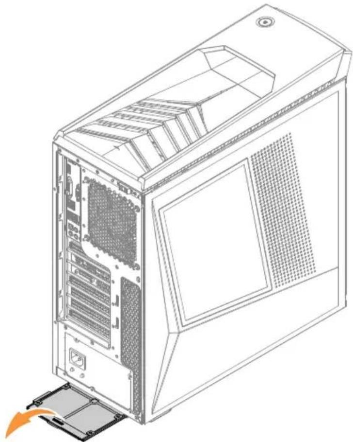
Step 5. Press then pull the out the rear dust screen as shown.
natural_image
Line drawing of a desktop computer tower case with visible internal partition and ventilation slots (no text or symbols)Step 6. Cleaning tips:
a. Us a brush gently brush through the dust screen to remove the dust. b. If cleaning the dust screen with clean water, make sure you dry the dust screen completely before put it back.
Step 7. To install the rear dust screen:
a. Line up the new dust screen with the chassis and push the screen into position.
Replacing the keyboard and mouse
Pseudo topic: DITA topic "file:/E:/HMM/Replacing%20the%20keyboard%20and%20mouse.dita" could not be parsed.
Removing the computer cover
Attention:
- Turn off the computer and wait 3 to 5 minutes to let it cool down before removing the cover.
- For this procedure, it helps to lay the computer on a flat, stable surface.
To remove the computer cover:
Step 1. Remove any media (disks, CDs, or memory cards) from the drives, shut down the computer, and turn off all attached devices.
Step 2. Unplug all power cords from electrical outlets.
Step 3. Disconnect all cables attached to the computer. This includes power cords, input/output (I/O) cables, and any other cables that are connected to the computer. Refer to “Locating connectors on the rear of the computer”.
Step 4. Slide the computer cover lock to unlock position, a then press the cover open button, computer cover will spring open b c

text_image
Diagram showing server rack with labeled components and directional arrows indicating file transfer or movementStep 5. Reinstall the computer cover:
a. Align the cover with the guide track on the computer case, then slide the cover in.
b. Push the cover till it's lock position.
c. Push the cover lock to lock position.
Removing the computer cover ii
Attention:
- Turn off the computer and wait 3 to 5 minutes to let it cool down before removing the cover.
- For this procedure, it helps to lay the computer on a flat, stable surface.
To remove the computer cover ii:
Step 1. Remove any media (disks, CDs, or memory cards) from the drives, shut down the computer, and turn off all attached devices.
Step 2. Unplug all power cords from electrical outlets.
Step 3. Disconnect all cables attached to the computer. This includes power cords, input/output (I/O) cables, and any other cables that are connected to the computer. Refer to “Locating connectors on the rear of the computer”.
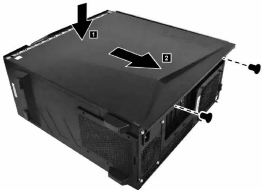
Step 4. Remove the 2 screws that secure the computer cover to the chassis.
Step 5. Press the left side of the cover, 1 then slide the computer cover out. 2
text_image
Diagram of a computer tower case with labeled components and directional arrows indicating assembly or installation steps.Step 6. Reinstall the computer cover ii:
a. Align the cover with the guide track on the computer case, then slide the cover in.
b. Press the left side the cover, then push it in till the cover locked properly.
c. Secure the computer cover with two screws.
Removing the front bezel
Note: For this procedure, it helps to lay the computer flat.
To remove the front bezel:
Step 1. Remove the computer cover. Refer to "Removing the computer cover".
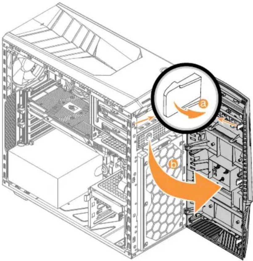
Step 2. Remove the front bezel by releasing the three plastic tabs inside the chassis and pulling the bezel out as shown.
text_image
Technical diagram of a desktop computer tower showing internal CPU socket and drive structure with labeled components (a) and (b)Step 3. To reattach the bezel, align the plastic tabs on the bottom of the bezel with the corresponding holes in the chassis, and then snap it into position.
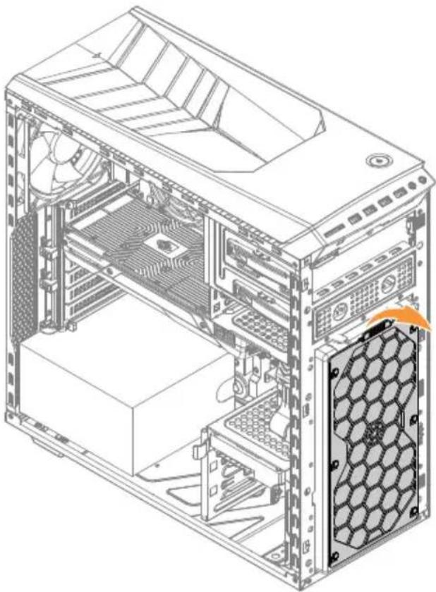
Cleaning front dust screen
To replace the system fan:
Step 1. Remove any media (disks, CDs, DVDs, or memory cards) from the drives, shut down the operating system, and turn off the computer and all attached devices.
Step 2. Unplug all power cords from electrical outlets.
Step 3. Disconnect all cables attached to the computer. This includes power cords, input/output (I/O) cables, and any other cables that are connected to the computer. Refer to “Left and right view” and “Rear view” for help with locating the various connectors.
Step 4. Remove the computer cover. Refer to "Removing the computer cover".
Step 5. Remove the computer cover. Refer to "Removing computer cover".
Step 6. Remove the front bezel. Refer to "Removing the front bezel".
Step 7. Pull the out the front dust screen as shown.
natural_image
Technical line drawing of a computer tower internal structure showing CPU socket, drive bays, and ventilation slots (no text or labels)Step 8. Cleaning tips:
a. Us a brush gently brush through the dust screen to remove the dust. b. If cleaning the dust screen with clean water, make sure you dry the dust screen completely before put it back.
Step 9. To install the front dust screen:
a. Line up the new dust screen with the chassis and push the screen into position.
Replacing a memory module
Note: For this procedure, it helps to lay the computer flat.
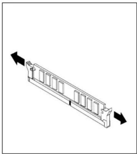
To replace a memory module:
Step 1. Remove the computer cover. Refer to "Removing the computer cover".
Step 2. Locate the memory module connectors. Refer to "Locating components".
Step 3. Remove the memory module to be replaced by opening the retaining clips as shown.
natural_image
Technical line drawing of a mechanical component with directional arrows indicating movement (no text or symbols)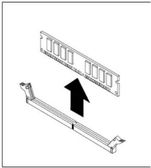
natural_image
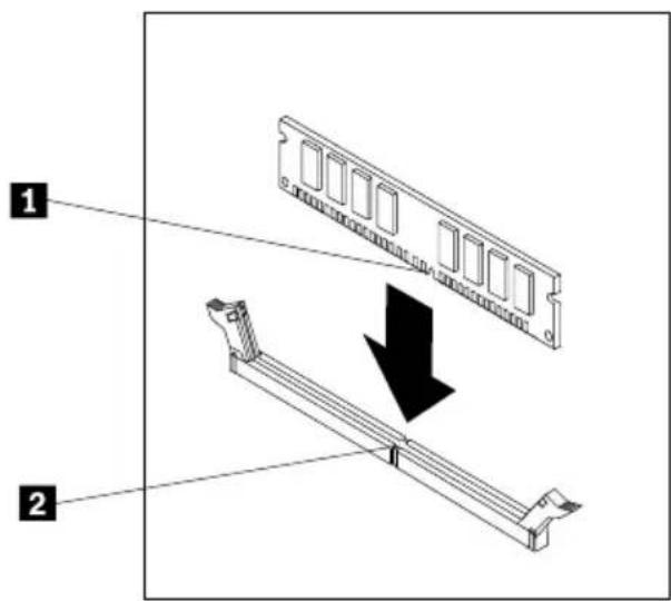
Technical illustration of a computer RAM module with an upward arrow indicating compression or assembly (no text or symbols present)Step 4. Position the new memory module over the memory connector. Make sure that the notch 1 on the memory module aligns correctly with the connector key 2 on the system board. Push the memory module straight down into the connector until the retaining clips close.
text_image
Diagram showing two views of a computer RAM module with labeled components and directional arrow indicating assembly or disassembly.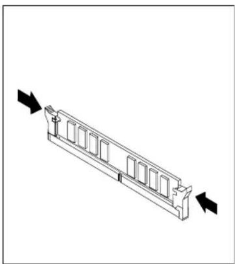
natural_image
Technical line drawing of a mechanical component with directional arrows indicating movement (no text or symbols)Step 5. Reattach the computer cover.
Replacing a hard disk drive
Note: For this procedure, it helps to lay the computer flat.
To replace a hard disk drive:
Step 1. Remove the computer cover. Refer to "Removing the computer cover".
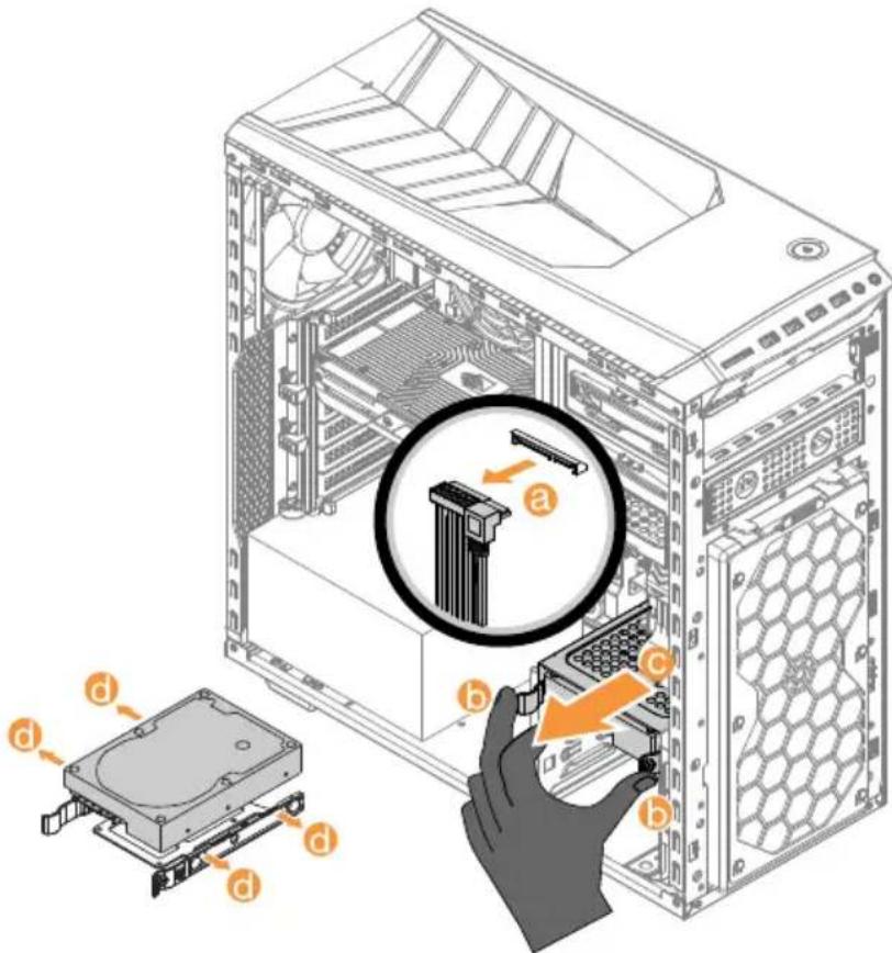
Step 2. Disconnect the data and power cables from the hard disk drive.
Step 3. Pull the plastic handle and slide the hard disk drive out of the drive bay.
b c
Release the hard disk drive from the bracket as shown.
text_image
Technical diagram showing computer hardware components with labeled parts (a, b, c) and a magnified inset highlighting internal structure.Step 4. Line up the new hard disk drive with the plastic bracket and snap it into position.
Step 5. Slide the new hard disk drive into the drive bay and slide the drive bay into place.
Step 6. Connect the power and signal cables to the new hard disk drive.
Step 7. Reattach the computer cover.
Replacing an optical drive
Note: For this procedure, it helps to lay the computer flat, stable surface.
To replace an optical drive:
Step 1. Remove the computer cover. Refer to "Removing the computer cover".
Step 2. Remove the front bezel. Refer to "Removing the front bezel".
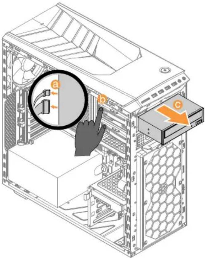
Step 3. Disconnect the data and power cables from the rear of the optical drive.
Step 4. Press the release button and push the optical drive straight out of the front of the chassis. b c
text_image
Diagram of a desktop computer tower showing internal components and a magnified view of the tower's cable interface with labeled parts a, b, and c.Step 5. Slide the new optical drive into the bay from the front until it snaps into position.
Step 6. Connect the data and power cables to the new disk drive.
Step 7. Reattach the front bezel and computer cover.
Replacing the microprocessor fan assembly
To replace the microprocessor fan assembly:
Step 1. Remove any media (disks, CDs, DVDs, or memory cards) from the drives, shut down the operating system, and turn off the computer and all attached devices.
Step 2. Unplug all power cords from electrical outlets.
Step 3. Disconnect all cables attached to the computer. This includes power cords, input/output (I/O) cables, and any other cables that are connected to the computer. Refer to “Left and right view” and “Rear view” for help with locating the various connectors.
Step 4. Remove the computer cover. Refer to "Removing the computer cover".
Step 5. Disconnect the fan power cable from the connector on the motherboard.
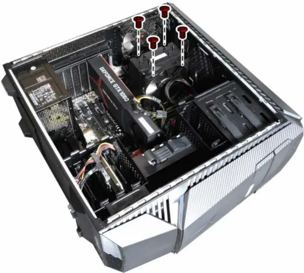
Step 6. Remove the 4 screws that secure the microprocessor fan to the heat-sink and lift up the microprocessor fan to remove it.
text_image
GEFORCE GTX1080Step 7. To install the new microprocessor fan assembly:
a. Line up the new microprocessor fan assembly with the heat-sink and secure it to the heat-sink with 4 screws.
b. Connect the microprocessor fan power cable to the connector on the board.
Step 8. Reattach the computer cover.
Replacing the rear system fan
To replace the system fan:
Step 1. Remove any media (disks, CDs, DVDs, or memory cards) from the drives, shut down the operating system, and turn off the computer and all attached devices.
Step 2. Unplug all power cords from electrical outlets.
Step 3. Disconnect all cables attached to the computer. This includes power cords, input/output (I/O) cables, and any other cables that are connected to the computer. Refer to “Left and right view” and “Rear view” for help with locating the various connectors.
Step 4. Remove the computer cover. Refer to “Removing the computer cover”. Step 5. Disconnect the fan power cable from the connector on the motherboard. Step 6. The system fan is locked to the computer case via plastic screw, use a knife cut off the plastic locking screws, then pull the rear system fan assembly out of computer case.

natural_image
Technical line drawing of a Lenovo desktop computer tower showing internal components like fan, drive, and ventilation (no text or labels)Step 7. To install the new system fan:
a. Line up the new system fan with the computer case and secure it to the computer case with locking screws by pulling the plastic screws through the locking hole.
b. Connect the system fan power cable to the connector on the board.
Step 8. Reattach the computer cover.
Step 1. Remove any media (disks, CDs, DVDs, or memory cards) from the drives, shut down the operating system, and turn off the computer and all attached devices.
Step 2. Unplug all power cords from electrical outlets.
Step 3. Disconnect all cables attached to the computer. This includes power cords, input/output (I/O) cables, and any other cables that are connected to the computer. Refer to “Left and right view” and “Rear view” for help with locating the various connectors.
Step 4. Remove the computer cover. Refer to "Removing the computer cover".
Step 5. Remove the computer cover ii. Refer to "Removing the computer cover ii".
Step 6. Remove the front bezel. Refer to "Removing the front bezel".
Step 7. Disconnect the fan from the connector on the motherboard.
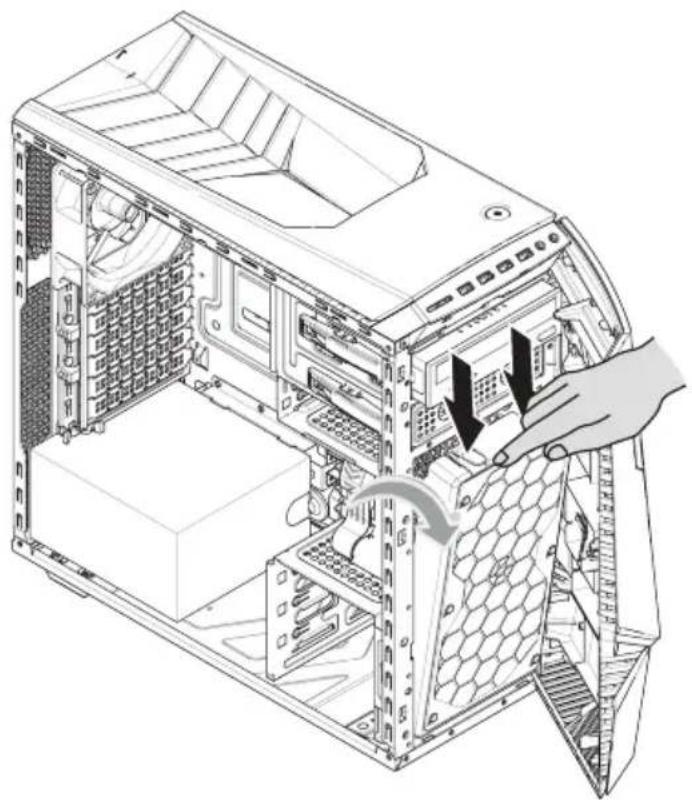
Step 8. The front fan and the bracket are mounted to the chassis with two pins. Press down the two pins as illustrated, then slide out the front fan and the bracket slowly.
natural_image
Technical line drawing of a computer tower internal structure showing internal components and a hand inserting a cable (no text or symbols present)Step 9. The front fan is pined to the brackets, push the pins outward to release the fan from the bracket ^1 , then lift up the fan to remove it.

text_image
Technical diagram of a desktop computer case with labeled internal components and numbered partsStep 10. To install a new fan:
a. Place the new fan with into the bracket, then secure the fan with the two locking pins.
b. Align the two locking pins at the bottom of the bracket with mounting holes on the chassis, then snap the fan and bracket into position.
c. Connect the new fan cable to the connector on the motherboard.
Step 11. Reattach the front bezel and the computer covers.
Replacing the Power supply
Note: For this procedure, it helps to lay the computer flat.
To replace the Power supply:
Step 1. Remove any media (disks, CDs, DVDs, or memory cards) from the drives, shut down the operating system, and turn off the computer and all attached devices.
Step 2. Unplug all power cords from electrical outlets.
Step 3. Disconnect all cables attached to the computer. This includes power cords, input/output (I/O) cables, and any other cables that are connected to the computer. Refer to “Left and right view” and “Rear view” for help with locating the various connectors.
Step 4. Remove the computer cover. Refer to "Removing the computer cover".
Step 5. Disconnect the power cables from the connectors on motherboard.
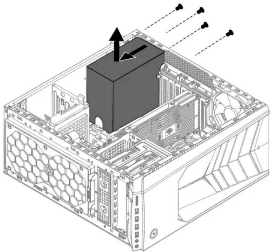
Step 6. Remove the 4 screws that secure the Power supply to the chassis.
Step 7. Slide then lift the Power supply out of chassis.
natural_image
Technical line drawing of a computer tower internal structure showing CPU socket, drive bays, and ventilation duct (no text or labels)Step 8. Install the new power supply :
a. Line up the holes on the new power supply with mounting holes on the rear of the chassis and secure it to the chassis with the 4 screws. b. Connect the power cables to the connectors on the motherboard.
Step 9. Reattach the computer cover.
Replacing the Wi-Fi card
Note: For this procedure, it helps to lay the computer flat.
To replace the Wi-Fi card:
Step 1. Remove any media (disks, CDs, DVDs, or memory cards) from the drives, shut down the operating system, and turn off the computer and all attached devices.
Step 2. Unplug all power cords from electrical outlets.
Step 3. Disconnect all cables attached to the computer. This includes power cords, input/output (I/O) cables, and any other cables that are connected
to the computer. Refer to "Left and right view" and "Rear view" for help with locating the various connectors.
Step 4. Remove the computer cover. Refer to "Removing the computer cover".
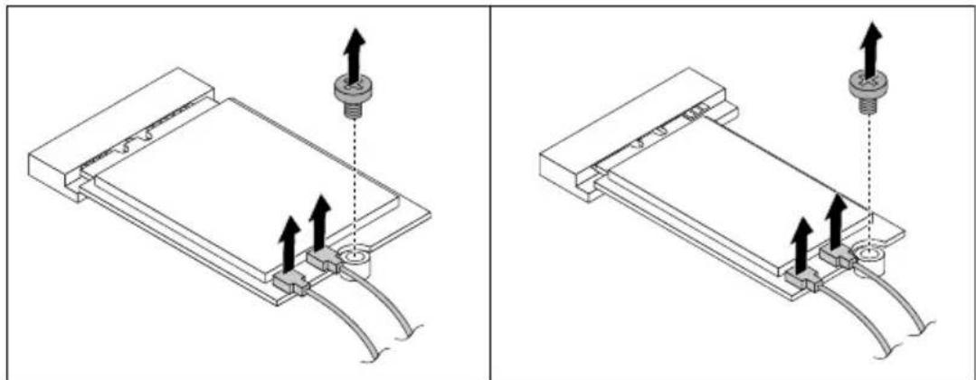
Step 5. Disconnect the 2 antenna cables from the Wi-Fi card.
Step 6. Remove the 2 screws that secure the Wi-Fi card to the motherboard.
Step 7. Pull the Wi-Fi card upward to remove it from the card port.
natural_image
Technical line drawings of a mechanical assembly with mounting holes and connectors (no text or symbols)Step 8. Install the new Wi-Fi card:
a. Line up the new Wi-Fi card, then insert it into the same card port. b. Secure the Wi-Fi card to the motherboard with the screw. c. Connect the 2 antenna cables to the new Wi-Fi card.
Step 9. Reattach the computer cover.
Removing the top cover
Attention:
- Turn off the computer and wait 3 to 5 minutes to let it cool down before removing the cover.
- For this procedure, it helps to lay the computer on a flat, stable surface.
To remove the top cover:
Step 1. Remove any media (disks, CDs, or memory cards) from the drives, shut down the computer, and turn off all attached devices.
Step 2. Unplug all power cords from electrical outlets.
Step 3. Disconnect all cables attached to the computer. This includes power cords, input/output (I/O) cables, and any other cables that are connected to the computer. Refer to “Locating connectors on the rear of the computer”.
Step 4. Remove the computer cover. Refer to "Removing the computer cover".
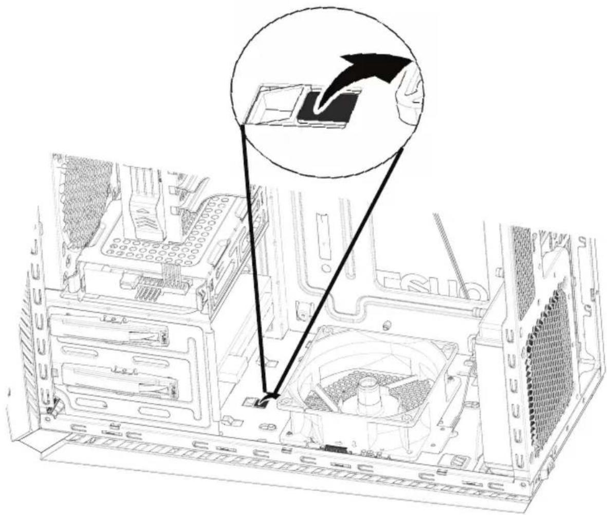
Step 5. Put the computer up side down, locate the top cover locking fin as shown. Use a flat head screw drivers to pry up the locking fin to release the top cover.
text_image
Technical diagram showing a computer tower with labeled components and an inset magnified view highlighting a device's internal structure.Step 6. Slide the top cover outward to remove the top cover as shown.
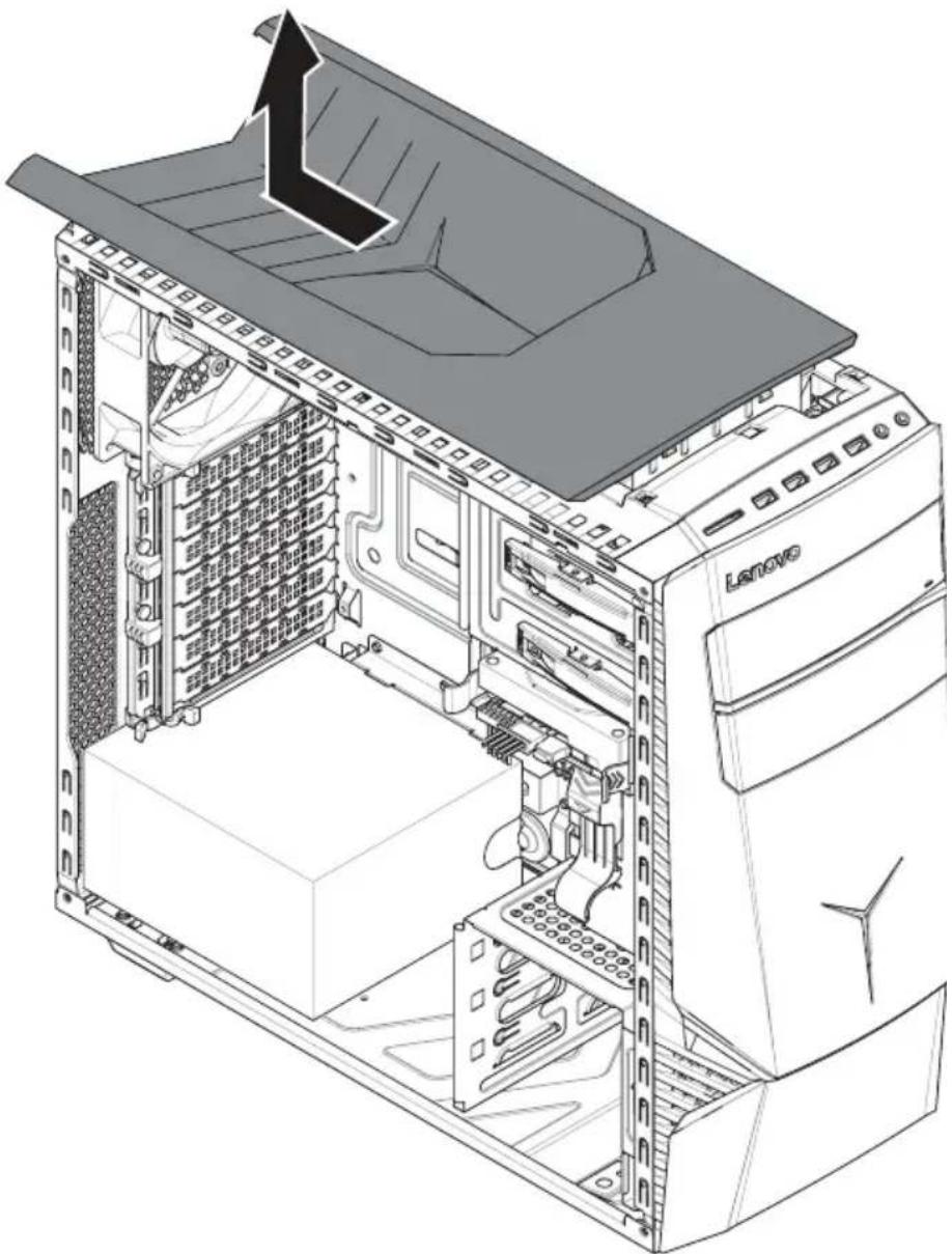
natural_image
Technical line drawing of a Lenovo desktop computer tower showing internal components and ventilation duct (no text or symbols)Step 7. Reinstall the computer cover:
a. Align the cover with the guide track on the computer case, then slide the cover in.
b. Push the cover till it's locking position.
c. Press down the locking fin to secure the top cover.
Step 8. Reattach the computer cover.
Replacing a graphics card
Note: For this procedure, it helps to lay the computer on a flat, stable surface.
To replace a graphics card:
Step 1. Remove the computer cover. Refer to "Removing the computer cover".
Step 2. Push the graphic card lock as shown to unlock the graphic.1
Step 3. Disconnect the power cables from the graphics card.
Step 4. Turn the locking pin counterclockwise 90^ , then slowly take it out.
Step 5. Push the locking pin that locks the graphic card to the motherboard 4, then lift the card straight up to remove it.5
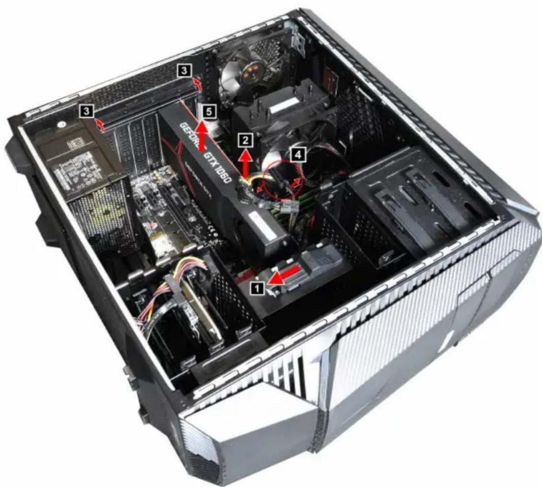
text_image
1 2 3 3 5 GECOM GTX 1060 4 1 3 4 1Step 6. To install the new graphics card:
a. Attach the new graphics card to the same adapter connector.
b. Connect the power cables to the new graphics card.
c. Turn the graphics card latch to the closed position and secure it with the locking pin.
Step 7. Reattach the computer cover.
Replacing the CPU
Note: For this procedure, it helps to lay the computer flat.
To replace the CPU:
Step 1. Remove any media (disks, CDs, DVDs, or memory cards) from the drives, shut down the operating system, and turn off the computer and all attached devices.
Step 2. Unplug all power cords from electrical outlets.
Step 3. Disconnect all cables attached to the computer. This includes power cords, input/output (I/O) cables, and any other cables that are connected to the computer. Refer to “Left and right view” and “Rear view” for help with locating the various connectors.
Step 4. Remove the computer cover. Refer to "Removing the computer cover".
Step 5. Remove the microprocessor fan. Refer to “Replacing the microprocessor fan”.
Step 6. Remove the CPU fan assembly. Refer to “Replacing the CPU fan assembly”.
Step 7. To remove the microprocessor 3 from the system board, press then slide the small handle out to spring it up.1 and open the retainer.2
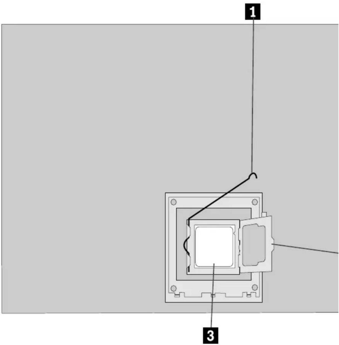
text_image
1 3Attention: Do not touch the gold contacts on the bottom of the microprocessor. When handing the microprocessor, touch only the sides.
Note: Do not drop anything onto the microprocessor socket while it is exposed. The socket pins must be kept as clean as possible.
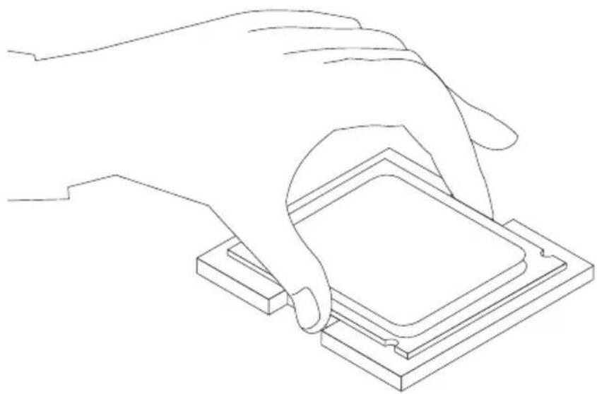
Step 8. Holding the sides of the microprocessor with your fingers, remove the protective cover 1 that protects the gold contacts on the new microprocessor. 2
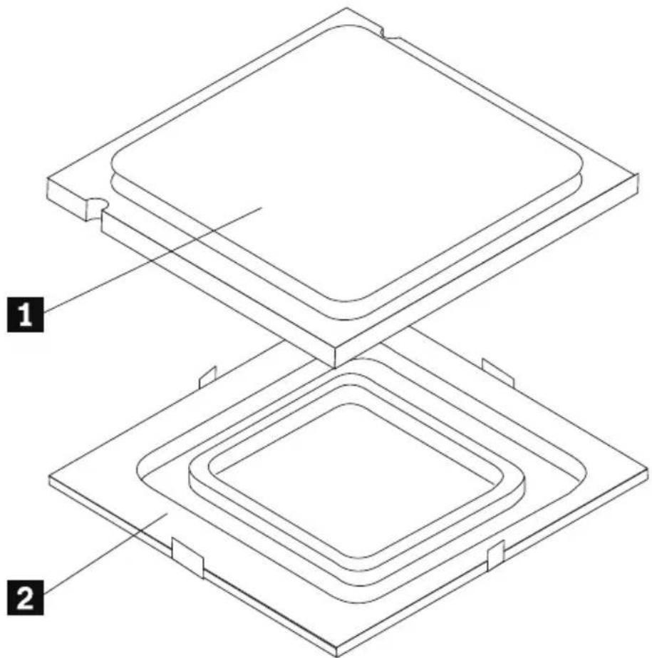
text_image
Technical diagram showing two layered electronic components with labeled parts 1 and 2Step 9. Holding the sides of the microprocessor with your fingers, position the microprocessor so that the notches on the microprocessor are aligned with the tabs in the microprocessor socket.
Important: To avoid damaging the microprocessor contacts, keep the microprocessor completely level while installing it into the socket.
Step 10. Lower the microprocessor straight down into its socket on the motherboard.
natural_image
Line drawing of a hand pressing a square component on a base (no text or symbols)Step 11. To secure the microprocessor in the socket, close the microprocessor retainer and lock it into position with the small handle.
Step 12. Use a thermal grease syringe to place 5 drops of grease on the top of the microprocessor. Each drop of grease should be 0.03ml (3 tick marks on the grease syringe).
Step 13. Reattach the CPU fan assembly, microprocessor fan, computer cover.
Replacing the motherboard
Note: For this procedure, it helps to lay the computer flat.
To replace the motherboard:
Step 1. Remove any media (disks, CDs, DVDs, or memory cards) from the drives, shut down the operating system, and turn off the computer and all attached devices.
Step 2. Unplug all power cords from electrical outlets.
Step 3. Disconnect all cables attached to the computer. This includes power cords, input/output (I/O) cables, and any other cables that are connected to the computer. Refer to "Left and right view" and "Rear view" for help with locating the various connectors.
Step 4. Remove the computer cover. Refer to "Removing the computer cover".
Step 5. Remove the memory module. Refer to "Replacing a memory module".
Step 6. Remove the microprocessor fan. Refer to "Replacing the microprocessor fan".
Step 7. Remove the heat-sink. Refer to "Replacing the heat-sink".
Step 8. Remove the graphic card. Refer to "Replacing a graphic card".
Step 9. Remove the Wi-Fi card. Refer to "Replacing the Wi-Fi card".
Step 10. Remove the CPU. Refer to "Replacing the CPU".
Step 11. Disconnect the all cables from the connectors on motherboard.
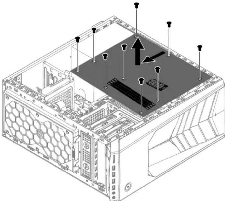
Step 12. Remove the 11 screws that secure the motherboard to the chassis.
Step 13. Slide then lift the motherboard out of the chassis to remove it.
natural_image
Isometric technical diagram of a computer tower with visible internal components and mounting points (no text or labels)Step 14. Install the new motherboard:
a. Line up the holes on the new motherboard with mounting holes on the chassis and secure it with screws.
b. Reattach the memory module, Wi-Fi card, CPU, and the heat-sink to the new motherboard.
c. Connect the all cables to the new motherboard.
d. Attach the graphic card to the new motherboard.
Step 15. Reattach the computer cover.
FRU lists
This chapter lists the information on the field replaceable units (FRUs).
Attention: Be sure to read and understand all the safety information before replacing any FRUs.
Lenovo Legion Y720T-34ASU Service Parts Listing
MT: 90H9
| FruP/N | Description |
| BDPLANAR | |
| 00XK277 | AMD Summit Ridge B350 WIN DPK |
| CABLE | |
| 04X2776 | Fru,500mm LED cable |
| 00XL138 Fru45 | 7mm SATA cable 2 latch |
| 00XL137 | Fru460mmSATAcable R_angle |
| 04X2777 | Fru,Gaming PCantenna cable_Black |
| 04X2778 | Fru,Gaming PCantenna cable_Gray |
| DT_KYB | |
| 00XH633 | USB Calliope KB BK NORDIC |
| 00XH621 | USB Calliope KB BK SWS |
| 00XH604 | USB Calliope KB BK HBW |
| 00XH605 | USB Calliope KB BK HUN |
| 00XH607 | USB Calliope KB BK ITA |
| 00XH598 | USB Calliope KB BK FRA |
| 00XH622 | USB Calliope KB BK THAI |
| 00XH630 | USB Calliope KB BK IND ENG |
| 00XH618 | USB Calliope KB BK SLK |
| 00XH602 | USB Calliope KB BK GRE |
| 00XH625 | USB Calliope KB BK UKE |
| 00XH619 | USB Calliope KB BK SPA |
| 00XH601 | USB Calliope KB BK GER |
| 00XH624 | USB Calliope KB BK TUR |
| 00XH611 | USB,Calliope,KB,BK,LA SPA |
| 00XH993 | USB Calliope KB BKCZE/SLK |
| 00XH627 | USB Calliope KB BK SLV |
| 00XH594 | USB Calliope KB BK TC/ENG |
| 00XH614 | USB Calliope KB BK POR |
| 00XH595 | USB Calliope KB BK CZE |
| 00XH626 | USB Calliope KB BK EURO ENG |
| 00XH593 | USB Calliope KB BK BUL |
| 00XH591 | USB,Calliope,KB,BK,BEL ENG |
| 00XH616 | USB Calliope KB BK RUS |
| 00XH610 | USB Calliope KB BK KOR |
| 00XH608 | USB Calliope KB BK JPN |
| 00XH587 | USB Calliope KB BK ENG |
| 00XH588 | USB Calliope KB BK ARA |
| 00XH635 | USB Calliope KB BK CAN ENG/FRA |
| FAN | |
| 00XD157 | Front System Fan |
| HDD_ASM | |
| 45K0623 | HDD,1TB,7200,DT3,SATA3,STD |
| 00PC552 | HDD,2TB,7200,DT3,SATA3,STD |
| 00PC551 | HDD,1TB,7200,DT3,SATA3,STD |
| HEATSINK | |
| 01MN125 AMD | SuR 95W CPU Cooler |
| LINECORD | |
| 00XL037 | Fru, LINECORD,AR,1.8M,3P,NON-LH |
| 00XL050 | Fru, LINECORD,TH,1.8M,3P,NON-LH |
| 00XL000 | Fru, JP,Anti-TR,1.8M,3P,NON-LH |
| 00XL047 | Fru, LINECORD,IT,1.8M,3P,NON-LH |
| 00XL023 | Fru, LINECORD,GB,1.8M,3P,NON-LH |
| 00XL031 | Fru, LINECORD,CH,1.8M,3P,NON-LH |
| 00XL029 | Fru, LINECORD,CH,1.8M,3P,NON-LH |
| 00XL027 | Fru, LINECORD,IL,1.8M,3P,NON-LH |
| 00XL024 | Fru, LINECORD,GB,1.8M,3P,NON-LH |
| 00XL005 | Fru, US/CA,1.8M,3P,NON-LH |
| 00XL025 | Fru, LINECORD,GB,1.8M,3P,NON-LH |
| 00XL014 | Fru, EU/KR,1.8M,3P,NON-LH |
| 00XL026 | Fru, LINECORD,IL,1.8M,3P,NON-LH |
| 00XL022 | Fru, LINECORD,IN,1.8M,3P,NON-LH |
| 00XL043 | Fru, LINECORD,AU,1.8M,3P,NON-LH |
| 00XL041 | Fru, LINECORD,AU,1.8M,3P,NON-LH |
| 00XL046 | Fru, LINECORD,DK,1.8M,3P,NON-LH |
| 00XL049 | Fru, LINECORD,IT,1.8M,3P,NON-LH |
| 00XL032 | Fru, LINECORD,BR,1.8M,3P,NON-LH |
| 00XL035 | Fru, LINECORD,AR,1.8M,3P,NON-LH |
| 00XL030 | Fru, LINECORD,CH,1.8M,3P,NON-LH |
| 00XL019 | Fru, LINECORD,TW,1.8M,3P,NON-LH |
| 00XL006 | Fru, US/CA,1.8M,3P,NON-LH |
| 00XL038 | Fru, LINECORD,ZA,1.8M,3P,NON-LH |
| 00XL001 | Fru, JP,Anti-TR,1.8M,3P,NON-LH |
| 00XL044 | Fru, LINECORD,DK,1.8M,3P,NON-LH |
| 00XL039 | Fru, LINECORD,ZA,1.8M,3P,NON-LH |
| 00XL034 | Fru, LINECORD,BR,1.8M,3P,NON-LH |
| 00XL010 | Fru, LINECORD,CN,1.8M,3P,NON-LH |
| 00XL015 | Fru, EU/KR,1.8M,3P,NON-LH |
| 00XL048 | Fru, LINECORD,IT,1.8M,3P,NON-LH |
| 00XL020 | Fru, LINECORD,IN,1.8M,3P,NON-LH |
| 00XL004 | Fru,US/CA,1.8M,3P,NON-LH |
| 00XL036 | Fru, LINECORD,AR,1.8M,3P,NON-LH |
| 00XL016 | Fru, EU/KR,1.8M,3P,NON-LH |
| 00XL042 | Fru, LINECORD,AU,1.8M,3P,NON-LH |
| 00XL017 | Fru, LINECORD,TW,1.8M,3P,NON-LH |
| 00XL028 | Fru, LINECORD,IL,1.8M,3P,NON-LH |
| 00XL033 | Fru, LINECORD,BR,1.8M,3P,NON-LH |
| 00XL045 | Fru, LINECORD,DK,1.8M,3P,NON-LH |
| 00XL040 | Fru, LINECORD,ZA,1.8M,3P,NON-LH |
| 00XL009 | Fru, LINECORD,CN,1.8M,3P,NON-LH |
| 00XL018 | Fru, LINECORD,TW,1.8M,3P,NON-LH |
| MECH_ASM | |
| 00XD537 | 34L,Top Bezel Cover,Destiny |
| 00XD538 | 34L,Top Bezel Base,Destiny |
| 01MN044 | 34L,Front Bezel ASSY,Y720 |
| 01MN142 | 34L,Chassis ASSY,Y720AMD |
| 00XD549 | 34L,L cover ,Y700 |
| 01MN143 | 34L,FIO ASSY,Y720AMD |
| 00XD545 | 34L,HDD Try ,Destiny |
| 00XD539 | 34L,Top Handle,Destiny |
| 00XD550 | 34L,R cover ,Y700 |
| MECHANICAL | |
| 00XD415 Y700 | GTX980/970 GFX bracket |
| MEMORY | |
| 01AG821 | 8GB DDR4 2666 UDIMM,Ramaxel |
| 01AG805 8GB | DDR4 2400UDIMM |
| 01AG815 | 8GB DDR4 2666 UDIMM,MICRON |
| MOUSE | |
| 00PH131 | USB Calliope Mouse Black(Orange wh |
| OPT_DRIVE | |
| 71Y5545 | SMD,DT,SATA,H/H,x16 |
| PWR_SUPPLY | |
| 54Y8930 | PWR_SUPPLY,100-240Vac,450W |
| SP | |
| 01AG127 | AMD Ryzen 7 1800X 3.6G/8C |
| 01AG138 | AMD Ryzen 5 1300 3.2G/4C/8M/AM4/65W |
| SSD_ASM | |
| 00UP448 | 128G,M.2,2280,PCIe3x4,SAMSG,STD |
| 00UP436 | 256G,M.2,2280,PCIe3x4,SAM,OPAL |
| 00UP641 | 256G,M.2,2280,PCIe3x4,TOS,OPAL |
| VIDEO_CARD | |
| 01AJ836 AMD | @RX480@8G D5 H+3DP |
| 01AJ876 MSI | @RX570@4G/D5/3-DP/HDMI/HP |
| WIRELESS | |
| 01AX713 | Wireless,CMB,LTN,NFA344A M2 |
| 01AX726 | Wireless,CMB,LTN,NFA344A FCC |
Chapter 9. General information
This chapter provides general information that applies to all machine types supported by this publication.
Additional Service Information
This chapter provides additional information that the service representative might find helpful.
Power management
Power management reduces the power consumption of certain components of the computer such as the system power supply, processor, hard disk drives, and some monitors.
Advanced configuration and power interface (ACPI) BIOS
As this computer has an ACPI BIOS system, the operating system is allowed to control the power management features of the computer and the settings for Advanced Power Management (APM) BIOS mode is ignored. Not all operating systems support ACPI BIOS mode.
Automatic Power-On features
The Automatic Power-On features within the Power Management menu allow you to enable and disable features that turn on the computer automatically.
- Wake Up on Alarm: You can specify a date and time at which the computer will be turned on automatically. This can be either a single event, a daily event or a weekly event.
- Wake Up on LAN: This feature allows LAN adapter card to wake the System.