AIM8 DT Three - Pregnant SpeakerCraft - Free user manual and instructions
Find the device manual for free AIM8 DT Three SpeakerCraft in PDF.


User questions about AIM8 DT Three SpeakerCraft
0 question about this device. Answer the ones you know or ask your own.
Ask a new question about this device
Download the instructions for your Pregnant in PDF format for free! Find your manual AIM8 DT Three - SpeakerCraft and take your electronic device back in hand. On this page are published all the documents necessary for the use of your device. AIM8 DT Three by SpeakerCraft.
USER MANUAL AIM8 DT Three SpeakerCraft
SPEAKER SPECIFICATIONS
| AIM8 DT One | AIM8 DT Three | |
| System Description: | Two tweeters mounted onto a dual voice coil woofer | Two tweeters mounted onto a dual voice coil woofer |
| High Frequency Drivers: | Dual 1" Resin coated Silk Dome Tweeters | Dual 1" Aluminum Dome Tweeters |
| Low Frequency Driver: | 8" Polypropylene Cone Woofer with Dual Voice Coil and Rubber Surround | 8" Aluminum Cone Woofer with Dual Voice Coil and Rubber Surround |
| Impedance: | 8Ω | 8Ω |
| Frequency Adjustments: | None | Front mounted treble/bass switch allows the treble/bass to be set at one of 3 positions: -3db, flat, +3db |
| Efficiency: | 91dB 1w/1m | 92dB 1w/1m |
| Frequency Response: | 45Hz - 20kHz | 40Hz - 20kHz |
| Power Recommendations: | 80 Watts (undistorted) | 100 Watts (undistorted) |
| Diameter x Depth: | 11716" × 534" (290.499mm × 146.050mm) | 11716" × 534" (290.499mm × 146.050mm) |
| Cut-Out Diameter: | 934" (247.650mm) | 934" (247.650mm) |
In our attempt to constantly improve our products, features and specifications are subject to change without notice.
SpeakerCraft offers a variety of accessories to make your installation of these speakers and other SpeakerCraft products easy, economical, and professional. Contact your authorized SpeakerCraft Dealer for more information. Should you have any questions regarding this, or any other SpeakerCraft product, please call our toll-free Service Hotline at 1-800-448-0976. We are available to assist you every weekday, except holidays, between the hours of 7:00 a.m. and 5:00 p.m. PST.
text_image
Declaration of Conformity CE We. Escondecollin Co. PBC Coorden Ave. Riverton, CA 2004 USA electrons under its mechanism that the products described in the water is much more or less in compliance with fluid/hacial standards EN 50364-2 EMC Emission CN 50367-2 MRC Immunity SpectraGen Inc. PBC Coorden Ave. Riverton, CA 2004 JN00 448-2074, Inc. 2911, 054640 www.spooland.comOWNER'S MANUAL
AIM8 DT
Single Stereo Speakers
AIM8 DT One / AIM8 DT Three
SPEAKER PLACEMENT
Before installing your speaker, you should consider the placement carefully, taking into account the location of electrical, plumbing and other fixtures. Contact your dealer for assistance if you are not sure of the best location in your particular room environment.
Ceiling Placement: When placing your speaker into the ceiling, it should ideally be located above the primary listening area. The DT is intended to be used as a single stereo speaker in small listening environments, walk-in closets, laundry rooms, bath rooms etc. In a large area, it may be necessary to place additional speakers throughout the room to get the optimal effect.
MOUNTING SURFACE PREPARATION
New Construction - Unfinished Ceilings
A New Construction Bracket, SpeakerCraft part number BKT90611 (available from your dealer), may be installed prior to drywall application across joists (up to 24" on-center) where a speaker will be located. Insulation material should be in place prior to installing drywall. After the hole is cut and the drywall is installed, the speaker can then be easily installed following the instructions for mounting under "Finished Ceilings" below.
Finished Ceilings
Prior to the actual installation of the speaker, it will be necessary to run cables to the speaker location. See your dealer for more information on cable installation. After the cable has been properly installed, you are ready to mount the speaker. Following the simple steps listed below will result in a professional looking installation:
- Determine the best area to mount your speaker. This area of the ceiling should be free of obstructions such as electrical conduit, HVAC ducts, or water lines. This can best be determined by noting the placement of fixtures and gaining access to an attic or crawl space for further analysis of the location of such obstacles.
- Find the joists nearest the desired speaker mounting location. We highly recommend using a good stud-finder tool for this procedure. If you are lining up the speaker to some other object or molding in the room, make sure you consider the size of the baffle flange which extends beyond the mounting hole.
-
Mark the hole. A punch out template for setting the hole is provided in the box. Position the template in the desired position and pencil an outline on the ceiling.
-
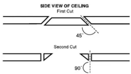
Cutting the hole. CAUTION: This is the most important part of the entire installation. If you are not certain whether any obstructions exist behind the desired mounting area, you should start by cutting a small hole in the center of your penciled mounting hole with a drywall saw, cutting at a 45^ angle towards the inside of the hole. (See Diagram 1)
Cutting the small hole at this angle will make drywall repair much easier, using the piece cut out. Once you have determined that there aren't any obstructions in your desired mounting location, start cutting the finished hole at a 90° angle to the ceiling's surface.
Diagram 1
text_image
SIDE VIEW OF CEILING First Cut 45° Second Cut 90°- Add insulation. If the area in the ceiling is not already insulated, add an adequate amount insulation material to loosely cover the back of the speaker. If the insulation material used is faced with foil or paper, position the foil or paper away from the speaker.
SPEAKER INSTALLATION
The unique integral four foot mounting system incorporated into your AIM DT speaker allows for a quick installation by following these easy steps.
- Remove the grille. It may be necessary to push one or two of the mounting screws, and its attached foot, towards the baffle and against the inside surface of the grille to force the grille out of its retaining groove.
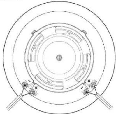
- Attach the speaker cable (observing the proper polarity with your amplifier, + to + and - to -). Either channel may be attached to either terminal set, however, be sure that polarity (+ and -) is correct on each channel or the performance of the speaker will be seriously affected, as one channel will cancel out the other. (See Diagram 2)
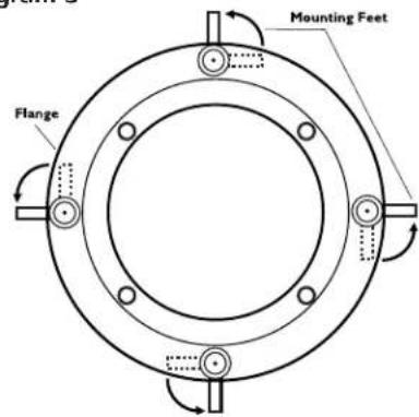
- Make sure the mounting feet are turned inward to clear the opening, and insert the speaker into the ceiling. Position the speaker into the hole. Note: The flange of the speaker is designed to flex and conform to any small imperfections in the ceiling's surface. Tighten the four screws on the front of the baffle only enough to make the flange become snug against the ceiling. As you tighten the screws, the feet will automatically flip into an outward position thereby clamping the drywall between the feet and the flange. (See Diagram 3)
CAUTION: Over tightening may warp the baffle, crack the ceiling, cause the flange to distort, and make the grille difficult to install.
- Push the grille firmly into the slot in the speaker baffle.
SPEAKER ADJUSTMENT
1. Adjusting the AIM8 DT Mechanism
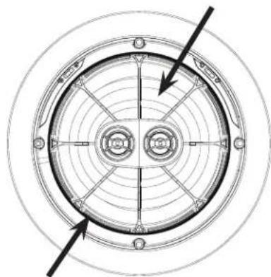
The woofer can be pivoted to best direct the sound towards the listener. The woofer easily rotates and pivots to almost any position desired. Simply apply pressure with fingertips to the outer surface of the PivotBall and move the speaker to the desired position (See Diagram 4).
2. Adjusting the Pivoting Tweeters
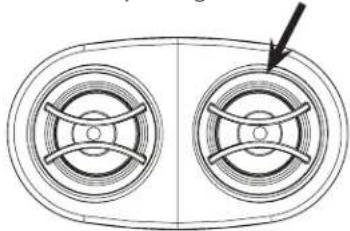
Once the woofer is positioned, further refinement can be made by pointing the tweeter towards the listener. Gently pivot the tweeter to point it in the desired direction (See Diagram 5).
ADJUSTING THE FREQUENCY RESPONSE (AIM8 DT Three)
The output of the woofer and tweeter on the AIM8 DT Three can be adjusted to suit any environment. In general, we recommend leaving all of the adjustments at the flat (0dB) setting. To determine which settings will be appropriate for your speakers, you may need to experiment until the desired sound is achieved. Use the chart to determine the result of the setting you select.
Selecting a Setting on AIM8 DT Three
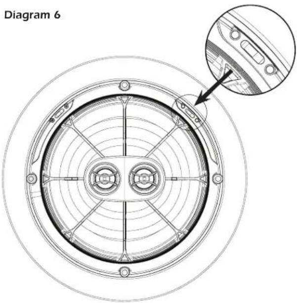
To select a setting, simply use a finger to move the switches mounted on the inner side of the speaker to the desired setting (See Diagram 6).
Diagram 2
natural_image
Technical diagram of a circular mechanical component with concentric rings and mounting brackets (no text or symbols)Diagram 3
text_image
Mounting Feet FlangeDiagram 4
Do NOT adjust by pushing on the WavePlane
natural_image
Technical diagram of a circular mechanical component with concentric rings and bolt holes (no text or symbols)Adjust direction by pushing the edges
Diagram 5
Pivot the Tweeter by gently pushing on the sides
natural_image
Technical line drawing of two circular components with internal cross-bracing, no text or symbols presentAIM8 DT Owner's Manual
Frequency Settings
When selected, the settings will have the following result:
-3dB: Reduces the loudness of the selected frequency (bass & treble)
0dB: The selected frequency (bass & treble) remains at neutral level
+3dB: Increases the loudness of the selected frequency (bass & treble)
PAINTING THE SPEAKER
If you plan to paint your speaker, we recommend that it be done prior to installation. If you plan to paint your speaker sometime in the future, it is best to remove it by simply reversing the steps for "Speaker Installation" listed above. If it is necessary to paint the speaker while it is still in the ceiling, the paint mask provided in the carton must be installed in place of the grille while the flange is being painted with the ceiling. The grille can also be painted, however, great care should be taken not to clog the holes as this will greatly reduce the sound quality of the speaker. SpeakerCraft recommends only light spray painting using 5 parts thinning agent to 1 part paint. Do not paint the grille while it is attached to the speaker.
text_image
Diagram 6LIMITED LIFETIME WARRANTY
SpeakerCraft Inc. warrants to the original retail purchaser only that this SpeakerCraft product will be free from defects in materials and workmanship, provided the speaker was purchased from a SpeakerCraft Authorized Dealer.
Defective products must be shipped, together with proof of purchase, prepaid insured to the SpeakerCraft Authorized Dealer from whom they were purchased, or to the SpeakerCraft factory at the address listed on this installation instruction manual. Freight collect shipments will be refused. It is preferable to ship this product in the original shipping container to lessen the chance of transit damage. In any case, the risk or loss or damage in transit is to be borne by the purchaser. If, upon examination at the Factory or SpeakerCraft Authorized Dealer, it is determined that the unit was defective in materials or workmanship at any time during this warranty period, SpeakerCraft or the SpeakerCraft Authorized Dealer will, at its option, repair or replace this product at no additional charge, except as set forth below. If this model is no longer available and can not be repaired effectively, SpeakerCraft, at its sole option may replace the unit with a current model of equal or greater value. In some cases where a new model is substituted, a modification to the mounting surface may be required. If mounting surface modification is required, SpeakerCraft assumes no responsibility or liability for such modification. All replaced parts and product become the property of SpeakerCraft Inc. Products replaced or repaired under this warranty will be returned to the original retail purchaser, within a reasonable time, freight prepaid.
This Warranty does not include service or parts to repair damage caused by accident, disaster, misuse, abuse, negligence, inadequate packing or shipping procedures, commercial use, voltage inputs in excess of the rated maximum of the unit, or service, repair or modification of the product which has not been authorized or approved by SpeakerCraft. This Warranty also excludes normal cosmetic deterioration caused by environmental conditions. This Warranty will be void if the Serial Number on the product has been removed, tampered with or defaced.
This Warranty is in lieu of all other expressed warranties. If the product is defective in materials or workmanship as warranted above, the purchaser's sole remedy shall be repair or replacement as provided above. In no event will SpeakerCraft be liable for any incidental or consequential damages arising out of the use or inability to use the product, even if SpeakerCraft Inc. or a SpeakerCraft Inc. Authorized Dealer
has been advised of the possibility of such damages, or for any claim by any other party. Some states do not allow the exclusion or limitation of consequential damages, so the above limitation and exclusion may not apply.
All implied warranties on the product are limited to the duration of this expressed Warranty. Some states do not allow limitation on the length of an implied warranty. If the original retail purchaser resides in such a state, this limitation does not apply.