MZC-64 - Receiver SpeakerCraft - Free user manual and instructions
Find the device manual for free MZC-64 SpeakerCraft in PDF.


User questions about MZC-64 SpeakerCraft
0 question about this device. Answer the ones you know or ask your own.
Ask a new question about this device
Download the instructions for your Receiver in PDF format for free! Find your manual MZC-64 - SpeakerCraft and take your electronic device back in hand. On this page are published all the documents necessary for the use of your device. MZC-64 by SpeakerCraft.
USER MANUAL MZC-64 SpeakerCraft
HARDWARE INSTALLATION INSTRUCTIONS
MZC-64
Multi-Zone Audio/Video Amplifier Controller
text_image
ZONE STATUS MASC-0-4 WATER 1 2 3 4 SITTING 2 LUNI/POWER Master Power SpeakerCraftSAFETY INSTRUCTIONS
CAUTION
RISK OF ELECTRIC SHOCK DO NOT OPEN

CAUTION: To reduce the risk of electric shock, do not remove cover, (or back).
No user serviceable parts inside. Refer servicing to qualified service personnel.

The lightning flash with arrowhead symbol, when in an equilateral triangle, is intended to alert the user to the presence of in-insulated "dangerous voltage" within the product's enclosure that may be of sufficient magnitude to constitute a risk of electric shock to persons.

The exclamation point, within an equilateral triangle, is intended to alert the user to the presence of important operating and maintenance (servicing) instructions in the literature accompanying the appliance.
APPLICABLE FOR USA, CANADA OR WHERE APPROVED FOR USAGE
CAUTION: TO PREVENT ELECTRIC SHOCK, MATCH WIDE BLADE PLUG TO WIDE SLOT, INSERT FULLY
ATTENTION: POUR EVITIER LES CHOCS ELECTRIQUES, INTRODUIRE LA LAME LA PLUS LARGE DE LA FICHE DANS LA BORNE CORRESPONDANTE DE LA PRISE ET POUSSER JUSQU AU FOND
Read all of these instructions before operating and save instructions for later use.
- Read Instructions – All the safety and operating instructions should be read before the appliance is operated.
- Retain Instructions – The safety and operating instructions should be retained for future reference.
- Heed Warnings – All warnings on the appliance and in the instructions should be adhered to.
- Follow Instructions – All operating and use instructions should be followed.
- Water and Moisture – The appliance should not be used near water – for example, near a bathtub, washbowl, kitchen sink, laundry tub, in a wet basement or near a swimming pool.
PORTABLE CART WARNING

- Carts and Stands – The appliance should be used only with a cart or stand that is recommended by the manufacturer. An appliance and cart combination should be moved with care. Quick stops, excessive force, and uneven surfaces may cause the appliance and cart combination to overturn.
- Wall or Ceiling Mounting – The appliance should be mounted to a wall or ceiling only as recommended by the manufacturer.
- Ventilation – The appliance should be situated so that its location or position does not interfere with its proper ventilation. For example, the appliance should not be situated on a bed, sofa, rug, or similar surface that may block the ventilation openings; or, placed in a built-in installation, such as a bookcase or cabinet that may impede the flow of air through the ventilation openings.
- Heat - The appliance should be situated away from heat sources such as radiators, heat registers, stoves, or other appliances (including amplifiers) that produce heat.
- Power Sources – The appliance should be connected to a power supply only of the type described in the operating instructions or as marked on the appliance.
- Grounding or Polarization – Precautions should be taken so that the grounding or polarization means of an appliance is not defeated.
- Power-Cord Protection – Power-supply cords should be routed so that they are not likely to be walked on or pinched by items placed upon or against them, paying particular attention to cords at plugs, convenience receptacles, and at the point where they exit from the appliance.
- Cleaning – The appliance should be cleaned only as recommended by the manufacturer.
- Power Lines - An outdoor antenna should be located away from the power lines.
- Nonuse Periods – The power cord of the appliance should be unplugged from the outlet when left unused for a long period of time.
- Object and Liquid Entry – Care should be taken so that objects do not fall and liquids are not spilled into the enclosure through openings.
- Damage Requiring Service – The appliance should be serviced by qualified service personnel when:
A. The power-supply cord or the plug has been damage; or
B. Objects have fallen, or liquid has spilled into the appliance; or
C. The appliance has been exposed to rain; or
D. The appliance does not appear to operate normally or exhibits a marked change in performance; or
E. The appliance has been dropped or the enclosure damaged.
- Servicing – The user should not attempt to service the appliance beyond that described in the operating instructions. All other servicing should be referred to qualified service personnel.
Contents
SAFETY INSTRUCTIONS....2
INTRODUCTION....5
PRODUCT FEATURES....5
SYSTEM OVERVIEW....6
KEYPAD CONFIGURATIONS 6
EZ-PAD FEATURE DESCRIPTIONS 7
MZC-64 FRONT PANEL 9
MZC-64 REAR PANEL....10
EPR-1.0 EZ-PAD RELAY MUTING MODULE 12
TYPICAL MZC-64 SYSTEM 13
SYSTEM PLANNING AND INSTALLATION 14
SYSTEM PLANNING 14
SYSTEM INSTALLATION....16
WIRING 16
KEYPADS 16
SPEAKERS 17
CONTACT CLOSURES....17
EXPANSION PORT/LOOP 17
RS232 17
CONTROL PORT 18
PHONE PAGE IN....18
DOORBELL/STATUS IN....18
COMMON IR OUT....18
COMMON STATUS OUT 18
SOURCE IR OUT 18
SOURCE IR LOOP 19
SOURCE AUDIO INPUT 19
SOURCE AUDIO LOOP....19
ZONE PRE-OUT 19
ZONE IR OUT 19
EZ-PAD CONFIGURATION 20
INSTALLATION 22
HEAD-END 22
CONNECTIONS - HEAD END....22
Keypads 22
External Source Components 22
Audio....22
Emitters (Source)....22
Speakers....22
Paging 23
Phone(Page In)....23
Doorbell/Status In (1&2) 23
Contact Closures 23
Expansion 23
RS232 Data I/O 23
Control Port 23
Common IR Out 23
Common Status Out....24
Zone Pre-Out 24
High-Power, Two Channel Amplifier - VC, Variable Output 24
Sub-Zone Expansion, Multi-Channel Amplifier - NVC, Fixed Output....24
Zone IR Out 24
MZC-64 Hardware Installation Instructions
INSTALLATION - ZONES 25
CONNECTIONS - ZONES 25
Keypads 25
Speakers....25
Direct Speaker Connection To MZC-64 Or Amplifier 25
Speaker Connection To EPR-1.0 EZ-Pad Relay Muting Module 25
Other Zone Connections....25
EXTERNAL AMPLIFIERS....27
ADDING A HIGH-POWER TWO-CHANNEL AMPLIFIER TO A ZONE 27
Installation....27
Connections And Configuration....27
ADDING A 12-CHANNEL AMPLIFIER TO A ZONE....29
Installation....29
Connections And Configuration....29
EXPANDED SYSTEMS 31
Installation....31
Connections And Configuration....31
Common Status Out....36
TROUBLESHOOTING 37
MZC-64 SPECIFICATIONS 38
LIMITED 2-YEAR WARRANTY.... 39
INTRODUCTION
Thank you for purchasing the SpeakerCraft MZC-64 Multi-Zone Audio Amplifier Controller. The MZC-64 contains the excellent performance and reliability that SpeakerCraft products have been recognized for. The MZC-64 features the flexibility needed for the most demanding custom installation applications. It is ideal for use in residential and commercial multi-zone applications. For best performance, please carefully read the instructions in this manual.
MZC-64 Is The Most Versatile Multi-Zone Audio Control Solution Available Today.
- Power In Amplification ... 8 channels of 30 watt state-of-the-art digital amplification for maximum efficiency in a small chassis.
- Power In Control...Complex control made simple with EZ-Pad's and IMKP's ability to execute single IR commands or complex macros with the press of a button. EZ-Pad and IMKP Keypads are the ONLY keypads available today that give the installer the ability to change the number of Source buttons based on the user's needs. MODE 3.1 offers additional flexibility with a 3.1" high-resolution color LCD for display of graphic 'Virtual Buttons' and metadata from iPods and SpeakerCraft Tuners and MODE Jukebox.
- Power In Programming...The flexibility of EZ-Tools Programming Software allows system design for any number of sources from one to six and the option to convert unused Source buttons to function buttons as needed. EZ-Tools programming is the most powerful and flexible multi-zone audio system programming software available today.
WHAT'S INCLUDED
1 - MZC-64 Multi-Zone Audio Amplifier Controller
1 - Power Cord
1 - IRE-3T Test Emitter
1 - MZC-64 Quick Start Guide
PRODUCT FEATURES
■ 4 Independent Zones (Expandable to 16)
■ 6 External Audio Source Inputs
■ 8 Channel Audio Amplifier @ 30 watts per channel
■ Source Power Management
■ Whole-House Party and Control Modes
■ Telephone and Audio Paging
- Doorbell Mute
■ 2 Programmable 12V Inputs for Doorbell/Page Trigger or Source Status
■ 1 Dry Contact Closure
■ RS232 Control I/O
■ RS485 Control I/O
■ 4 Configurable Preamp Outputs (One per Zone)
■ 1 Common IR Output
■ 4 Zone IR Outputs (One per Zone) for Dedicated Zone Source Control
■ 6 Audio Loop-Throughs for easy Connections in Expanded Systems
■ 6 IR Loop-Throughs for Source Control in Expanded Systems
■ Rear Panel Programming Port
■ Upgradable Firmware
■ Programmed With EZ-Tools Programming Software
■ 2 Year Warranty
IMPORTANT NOTE
THIS MANUAL ONLY COVERS INSTALLATION AND HOOKUP. THOUGH CAPABLE OF SOME BASIC FUNCTIONS OUT OF THE BOX SUCH AS ON/OFF, SOURCE SELECTION AND VOLUME/MUTE, CONFIGURATION OF MZC-64 ADVANCED FEATURES REQUIRES SPEAKERCRAFT EZ-TOOLS PROGRAMMING SOFTWARE. EZ-TOOLS AND THE EZ-TOOLS MZC PROGRAMMING INSTRUCTIONS CAN BE DOWNLOADED FROM: www.speakercraft.com.
SYSTEM OVERVIEW
The SpeakerCraft MZC-64 System consists of four subsystems. First, the Keypads, (EZ-Pad, IMKP, MODE 3.1, not included) can be setup in a variety of configurations to meet virtually any client requirement. They are connected via convenient CAT-5 cable with home run lengths of up to 1000' (305m), to the centrally located MZC-64 Multi-Zone Audio Amplifier Controller and source components. The MZC-64 contains the "brains" of the system, taking key location data (button presses) from the keypads to trigger IR, RS232 and RS485 commands to control system functions and source components. Programming is accomplished using EZ-Tools, a SpeakerCraft developed Windows® software system. A fourth item, the LTM-1.0 Learning Test Module, is an installer's tool (not included) for learning and teaching special IR commands that are not included in the EZ-Tools Command Library.
KEYPAD CONFIGURATIONS
EZ-PAD
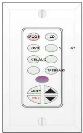
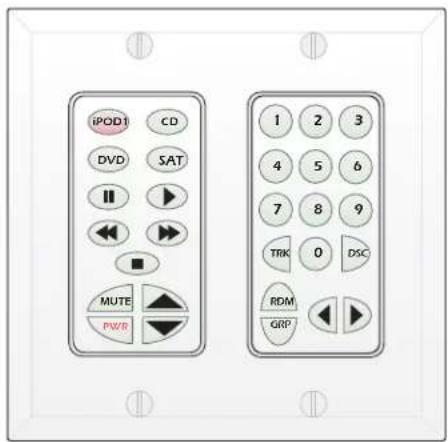
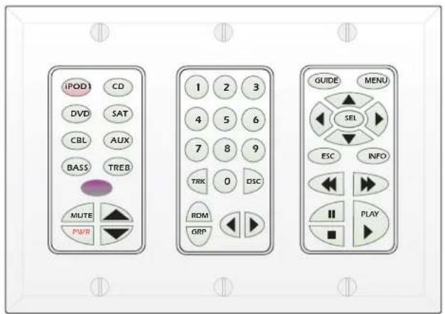
One keypad option for MZC-64 system control is the SpeakerCraft EZ-Pad System. EZ-Pads can be configured in single, double or triple-gang configurations as shown in Figure 1. (Decorator style cover plates are not included. Screw-less "Snap-On" type cover plates can also be used. Each keypad module must be ordered separately.)
Each keypad comes with a set of factory installed "default buttons" plus a good variety of additional buttons for changes to the default configuration. The default buttons can be easily changed to meet the needs of any installation. Additional buttons are available separately for purchase. See the SpeakerCraft Catalog and Price Sheet for the latest availabilities or call SpeakerCraft Customer Service.
text_image
iPODI CD DVD S CBLAUX TREBBASS MUTE PWR ATMKP-1.1
(optional)
Single Gang
text_image
iPOD1 CD DVD SAT MUTE PWR 1 2 3 4 5 6 7 8 9 TRK 0 DSC RDM GRPMKP-1.0
(optional)
Two Gang
text_image
iPOD CD DVD SAT CBL AUX BASS TREB MUTE PWR 1 2 3 4 5 6 7 8 9 TRK 0 DSC ROM GRP GUIDE MENU SEL ESC INFO II PLAYMKP-1.1
NKP-1.0
(optional)
Three Gang
FKP-1.0
Figure 1 EZ-Pad Gang Configurations
IMKP
Another option for MZC-64 System control are the SpeakerCraft IMKP Series Keypads. The IMKPs are a Euro-Design version of the EZ-Pads that have similar functionality in a mechanical package that fits European style in-wall junction boxes. They are available in 2 and 3 gang configurations and each includes a SpeakerCraft IR Receiver with ANS. See: IMKP-2.1/IMKP1.1 Installation Instructions for additional information. IMKP-2.1/IMKP1.1 Installation Instructions can be downloaded from www.speakercraft.com.
MODE 3.1
The third, and best option for MZC-64 system control is the SpeakerCraft MODE 3.1. MODE 3.1 is a graphic display keypad that combines the convenience and configurability of EZ-Pad/IMKP style hard keys with graphic 'Virtual Buttons' that can be created in EZ-Tools for any function imaginable. In addition MODE 3.1 displays metadata from the MZC as well as iPod (when controlled with a SpeakerCraft MODE Base), SpeakerCraft Tuners and MODE Jukebox. MODE 3.1 requires a special mounting bracket and bezel both of which are included with MODE 3.1. See: MODE 3.1 Installation Instructions for additional information. MODE 3.1 Installation Instructions can be downloaded from www.speakercraft.com.
EZ-PAD FEATURE DESCRIPTIONS
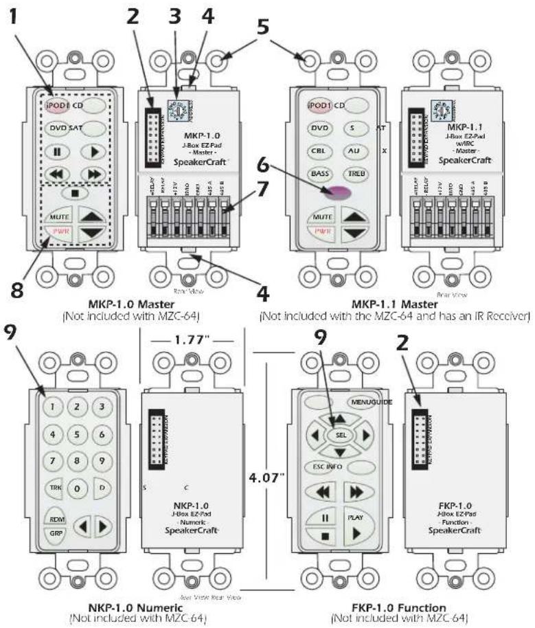
EZ-Pads come in four basic modules as shown. The MKP-1.0 and MKP-1.1 are Master Keypads and one must be used in each MZC-64 Zone using a keypad. The MKP-1.1 features a built-in IR receiver and has one less function button than the MKP-1.0, but are otherwise identical. The NKP-1.0 Numeric and FKP-1.0 Function key modules may be thought of as "slaves" to the Master Keypad (they will not work alone), providing more buttons for additional numeric and function commands. MKPs, IMKPs, and MODE 3.1s will all work right out of the box for basic functions such as Source Select /ON, Volume/Mute and OFF. Configuration of advanced features and source control requires programming with EZ-Tools.
text_image
1 2 3 4 5 iPOD1 CD DVD SAT MUTE PWM 8 MKP-1.0 Master (Not included with MZC-64) MKP-1.1 Master (Not included with the MZC-64 and has an IR Receiver) 9 NKP-1.0 Numeric (Not included with MZC-64) FKP-1.0 Function (Not included with MZC-64) 4.07" 1 2 3 4 5 6 7 8 9 TRK 0 D RDM GRP S C NKP-1.0 J-Box EZ-Pad Numeric SpeakerCraft iPod1 CD DVD S CBL AU BASS TRLD MUTE PWM AT X MTUER Rear Voice MKP-1.1 J-Box EZ-Pad w/WPC -Master SpeakerCraft FKP-1.0 J-Box EZ-Pad -Function SpeakerCraftFigure 2 EZ-Pad Features
- MKP-1.0/MKP-1.1 SOURCE/FUNCTION BUTTONS – Any of this set of eight buttons can be programmed as a Source Select or transport/function button for the MZC-64. One of the eight must always be designated as a Source Button. When the system is off, all buttons have a background green color. When a source button is pressed, it turns to a low-level red color to show the active source and the system is on in that zone. (Backlight Timeout can be set in EZ-Tools for EZ-Pad and IMKP. MODE 3.1 Backlight is configured in the MODE Keypad Settings Menu.)
- KEYPAD EXPANSION TERMINAL – This 16-pin header terminal is used to inter-connect EZ-Pad modules for expansion as needed. A 3-connector ribbon cable is packed with each NKP-1.0 and FKP-1.0 module for making these connections.
-
ADDRESS SWITCH – An unique hex address must be set for each Master Keypad when connected on a common bus within a single zone. Unique addresses are not required zone-to-zone (one keypad per zone). It provides up to 16 addresses (0 to F).
-
SNAP TABS – These tabs hold the decorator style insert panel to the metal mounting plate and are easily released for changing buttons.
- MOUNTING PLATE – Standard plate allows the keypad module to be attached to standard in-wall J-Boxes using the 2 screws provided. Also allows attachment of standard and screw-less, snap-on decorator type cover plates.
- IR RECEIVER LENS – The MKP-1.1 includes SpeakerCraft's exclusive ANS (Ambient Noise Suppressor) IR Receiver, built-in. The IR Receiver allows use of a handheld remote for control of the system and IR controlled source components.
- EZ-CONNECT TERMINALS – These seven spring-loaded terminals accept wire sizes 14 to 28 AWG for connection of the following:
- +RELAY/-RELAY – For connection of the external EPR-1.0 EZ-Pad Relay Speaker Muting Module. (Refer to Designated Relay Mute Key section and Figures 6 & 19).
- +12V DC – Powers the Keypad, including the internal IR Receiver on the MKP-1.1. Includes reverse voltage protection.
- IR/IO – Sends IR control signals for control of system components.
- GND – Return for Power, IR signal and Data.
-
485 A/485 B – Balanced, bi-directional system communications data.
-
FUNCTION BUTTONS – These lower 5 buttons (4 buttons on the MKP-1.1) are primarily used for volume, mute and power, but can also be programmed for any function except source select. These buttons glow a low-level background green and do not change color when pressed. Button background lighting can be programmed to go off after a set time of inaction, or stay on continuously as programmed in EZ-Tools.
-
NUMERIC AND FUNCTION BUTTONS – These buttons are used for direct numeric access of discs and tracks, selection of tuner presets, transport functions and menu navigation. All numeric and function buttons, including those on the Master Keypads, glow a low-level background green and do not change color when pressed. This background lighting can be programmed to go off after a set time of inaction, or stay on continuously as programmed in EZ-Tools.
FEATURE DESCRIPTIONS
MZC-64 FRONT PANEL
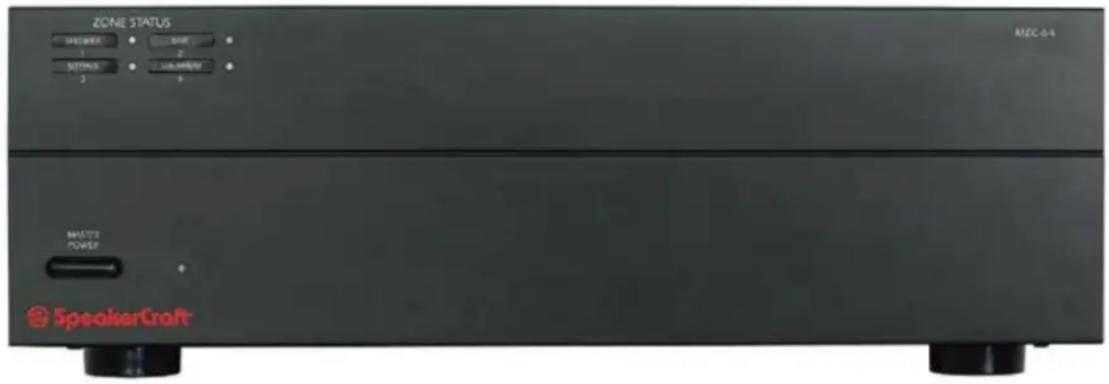
The MZC-64 is an 4-Zone, 6-Source Audio Amplifier Controller. It serves as the "brains" of the entire keypad system and provides audio switching and control for six external sources. Eight 30W/channel digital audio power amplifiers provide clean, powerful audio for up to four zones.
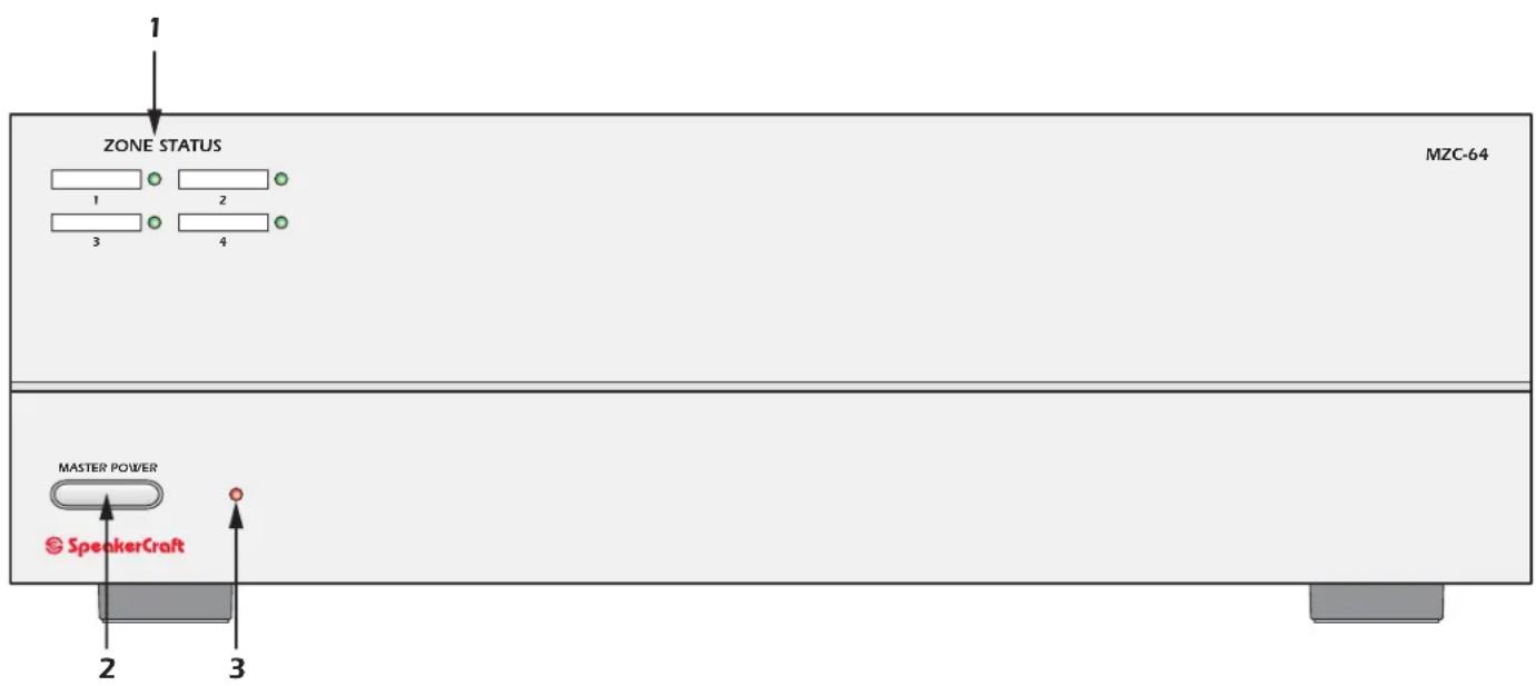
The Front Panel features a Master Power ON/OFF Switch and indicator and Zone ON/OFF Status is also displayed on the front panel to show system activity.
The Rear Panel is neatly laid out to provide clear access for all system control, audio, paging and trigger connections.
System Programming is done via connections on the Rear Panel.
text_image
1 ZONE STATUS MZC-64 1 2 3 4 MASTER POWER SpeakerCraft 2 3Figure 3
MZC-64 Front Panel Features
- ZONE STATUS LED INDICATORS AND LABELS – Four, green LEDs indicate the zones that are currently active. Indented spaces accept adhesive backed labels for zone/room identification. A sheet of descriptive labels, typical of room or area names used in homes, are included.
- MASTER POWER SWITCH – When pressed to the in position, the MZC-64 is placed in the power ON standby condition, permitting individual zones to be turned ON and OFF by keypad or touch panel commands. In the OFF (out) position, power from the AC mains is completely turned off.
- RED INDICATOR LED – Indicates when the Master Power switch is in the depressed position and that power has been applied from the AC mains.
MZC-64 REAR PANEL
text_image
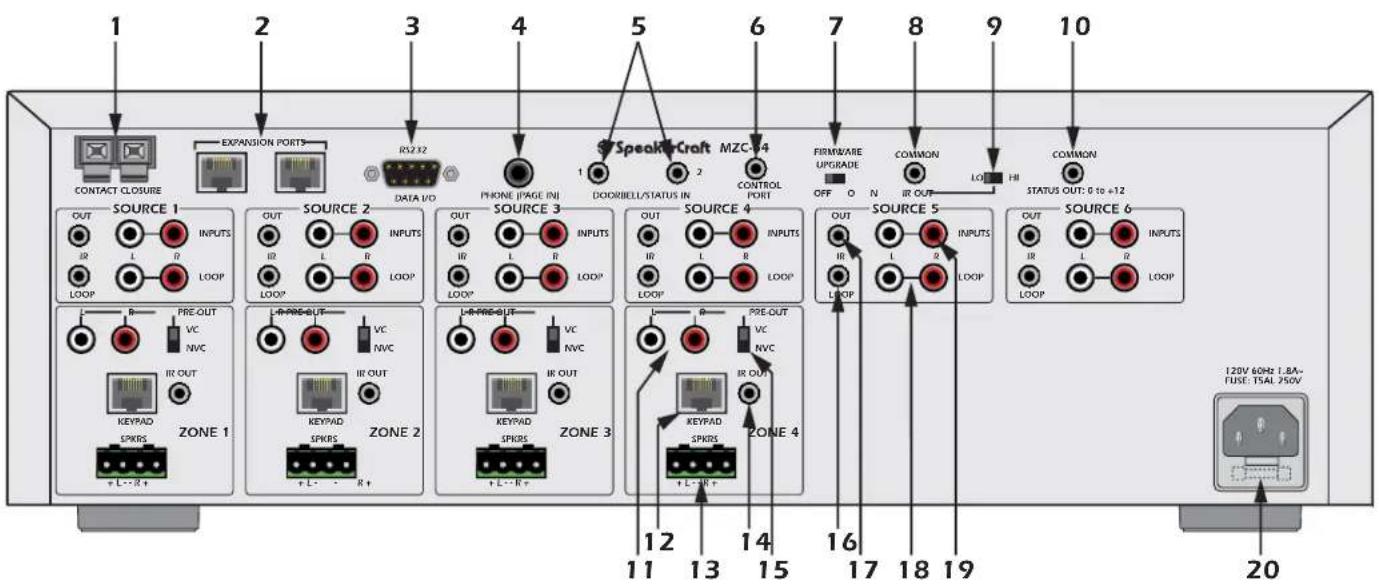
1 2 3 4 5 6 7 8 9 10 CONTACT CLOSURE EXPANSION PORTS RS2 R2 DATA VD PHONE PAGE INI DOORBELL/STATUS IN CONTROL PORT FIRMWARE UPGRADE OFF O N COMMON IR OUT LOOP COMMON STATUS OUT: 0 to +12 SOURCE 1 OUT INPUTS IR L II LOOP SOURCE 2 OUTPUT INPUTS IR L II LOOP SOURCE 3 OUTPUT INPUTS IR L II LOOP SOURCE 4 OUTPUT INPUTS IR L II LOOP SOURCE 5 OUTPUT INPUTS IR L II LOOP SOURCE 6 OUTPUT INPUTS IR L II LOOP SOURCE 1 PRE-OUT VC NVC IR OUT KEYPAD SPKRS ZONE 1 ZONE 2 ZONE 3 L-R PRE-OUT VC NVC IR OUT KEYPAD SPKRS + L - R + + L - R + ZONE 4 12 13 14 15 16 17 18 19 120V 60Hz 1.8A- FUSE: TSAL 250V 20Figure 4 MZC-64 Rear Panel Features
- CONTACT CLOSURE — One, single pole dry relay contact used to activate any device that can be controlled or triggered by a switch closure. The closure can be programmed within EZ-Tools for Momentary, Toggle and Open/Close Paired operation. Spring loaded terminals accept wire sizes from 28 to 14 AWG. Internal relay contacts are rated at 2A/30V AC or DC.
- EXPANSION PORT/LOOP — Two, RJ45 jacks primarily used for looping system data to multiple MZC-64's in expanded systems. These jacks can also be used for connection of specialized RS485 controlled products such as the SpeakerCraft MODE Base for adding iPods and additional Sources. (See: MODE 3.1 Installation Instructions for additional information.) These connections can also be used with the SpeakerCraft RSA-1.0 Remote Serial Adapter for control of up to 16 RS232 devices. (See: RSA-1.0 Installation Instructions for additional information.)
- RS232 DATA I/O — One, DB9F terminal allows the MZC-64 to control certain RS232 compatible devices such as source components and lighting systems. The RS232 Data I/O is currently a control out only and does not allow display of RS232 controlled device status information or RS232 control of the MZC-64.
- PHONE PAGE IN — One, RCA jack provides input for line level audio source such as telephone systems, door mics or other audio paging sources. This jack is programmable in EZ-Tools, to turn on as an event, when triggered by the DOORBELL/STATUS IN Jacks, item 5.
- DOORBELL/STATUS IN 1 & 2 — Two, 3.5mm mini jack trigger inputs work in conjunction with the PHONE PAGE IN jacks, item 4. When triggered, the Phone input can be turned on in selected zones as programmed in EZ-Tools. If Audio paging is not required, these jacks can also be programmed as STATUS INPUTS for power management of Source or Zone components. POLARITY: TIP= +V; SLEEVE=GND. INPUT VOLTAGE: 3-30V AC or DC to trigger the ON condition. Voltage must drop below 1V AC or DC for OFF.
- CONTROL PORT — One, 3.5mm 4-circuit mini jack used for all Controller and Keypad programming. It also accommodates factory firmware upgrades in conjunction with the FIRMWARE UPGRADE ON/OFF SWITCH. See: EZ-Tools MZC Programming Instructions for additional information.
-
FIRMWARE UPGRADE ON/OFF SWITCH - One, two position switch enables the MZC-64 Control Port for Firmware Upgrades. See: EZ-Tools MZC Programming Instructions for additional information.
-
COMMON IR OUTPUT — One, 3.5mm mini jack outputs all IR commands from IR sensors and Keypads regardless of zone origin. POLARITY: TIP= SIGNAL; SLEEVE=GND.
- HI/LO SWITCH — One, two position switch, sets high or low IR power output to the Common IR Output jack. Set to the LO setting when driving standard low power emitters (SpeakerCraft IRE-1.0, 2.0, 3.0 and 4.0). Set to HI when driving a high power emitter (SpeakerCraft IRE-5.0 Blaster) for teaching IR commands into learning remotes. HI OUTPUT: 110mA; LO OUTPUT: 13mA. CAUTION: THE HI POSITION WILL SMOKE LOW POWER EMITTERS!
- COMMON STATUS OUT — One, 3.5mm mini jack will go high (+12V DC) when any zone is turned ON and will go LOW (under 1V DC) when the last zone is turned OFF. POLARITY: TIP=+12V DC; SLEEVE=GND. MAX OUTPUT: 100 mA at 9.5V DC.
- L & R PRE-OUT — Two, RCA jacks, one pair per Zone, provide left and right line-level audio outputs for driving external high-power/audiophile two-channel amplifiers in large or outdoor zones or a critical listening zone, or driving a multi-channel amplifier for additional rooms, (sub-zone expansion) where needed.
- KEYPAD — Four, RJ45 jacks, one per zone, connect zone keypads to the MZC via CAT-5 or better. Configured for T568B Standard pin-out. Allows runs of up to 1000'.
- L & R SPEAKERS — Four, removable screw-down connectors, one terminal per zone, provide quick connection of the internal amplifiers to Zone stereo speaker pairs. WIRE GAUGE: 14 to 28 AWG.
- IR OUT (Zone) — One, 3.5mm mini jack, one per zone, provides dedicated Zone IR output for exclusive control of a specific zone component. (i.e., a dedicated satellite receiver or DVD player, that cannot be controlled from any other zones). POLARITY: TIP= SIGNAL; SLEEVE=GND.
- VC/NVC — Four, two-position switches, one per zone, switch the PRE-OUT jacks to VC - internal Volume Control (variable, zone volume controlled by keypads or IR remote) or NVC - No Volume Control (fixed, zone volume controlled by in-wall volume control or volume control on an external device such as an A/V Receiver). In either case, the tone control action remains available for room "EQ" settings.
- IR LOOP — Six, 3.5mm mini jacks, one per Source, provide connections for an IR signal path for external common source components, when using multiple MZC-64's in expanded systems. i.e. If using two MZC-64s, the SOURCE IR OUTS on the MZC Slave unit would connect to the appropriate SOURCE IR LOOPS on the MZC Master unit to pass Source IR commands between controllers from expanded zones. The IR OUTS on the Master connect to IR EMITTERS attached to the source components for source IR control from all zones. POLARITY: TIP= SIGNAL; SLEEVE=GND.
- IR OUT (Source) — Six, 3.5mm mini jacks, one per Source, output IR commands to external common source components. When a source is selected, from a keypad or remote control, IR commands are routed directly to that source. This allows selective control of multiple same-brand, same-model source components (multiple Satellite Receivers, DVD Players etc). POLARITY: TIP= SIGNAL; SLEEVE=GND.
- L & R LOOP (Source Left/Right Audio Loop) — Twelve, RCA jacks, two per Source, provide buffered left and right line-level audio outputs that are typically used to loop Source Audio signals to additional zone inputs on Slave MZC-64's in expanded systems. i.e. The L & R LOOP on the MZC Master would connect to the appropriate L & R INPUT on MZC Slave 1. Slave 1 would then loop to Slave 2, etc. These outputs can also be used to drive local components, such as a local surround receiver, when not used for expansion.
- L & R INPUT (Source Left/Right Audio Input) — Twelve RCA jacks, two for each Source, provide left and right line-level audio signal inputs for up to six external common source components.
- IEC TYPE AC MAINS RECEPTACLE AND FUSE — One, Standard IEC 3-conductor AC line cord receptacle, connects to included AC power cord. Also houses the rear panel replaceable AC mains fuse (T5AL 250V).
EPR-1.0 EZ-PAD RELAY MUTING MODULE
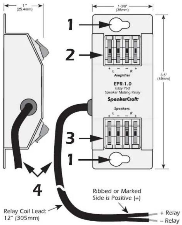
The EPR-1.0 EZ-Pad Speaker Muting Relay Module allows local speaker muting in any room with an EZ-Pad. Example: An MZC-64 Zone PRE-OUT feeding a multi-channel amplifier for sub-zone expansion. Each of the additional 'rooms' would utilize one stereo pair speaker-level output from the multi-channel amp, have a keypad for system and source control and each keypad would have an EPR-1.0 to mute the local speakers. All rooms in the zone would have the same ON/OFF status and play the same source. Individual room mute could then be controlled either from a keypad or an appropriately programmed IR Remote. EPR-1.0 is also fully compatible with IMKP and MODE 3.1.
text_image
1" (25.4mm) 1 1-3/8" (35mm) 3.5" (89mm) EPR-1.0 Eazy Pad Speaker Muting Relay SpeakerCraft* Speakers L - - R + Ribbed or Marked Side is Positive (+) Relay Coil Lead: 12" (305mm) + Relay - RelayFigure 6. EPR-1.0 EZ-Pad Relay Features
- MOUNTING HOLES — Two, keyholes, use these holes to mount the EPR-1.0 to any flat surface (usually to the studding in the wall behind the EZ-Pad or the in-wall speakers).
- "AMPLIFIER" EZ-CONNECT TERMINALS — Four, spring-loaded terminals connect to the amplifier L & R speaker level output terminals. WIRE GAUGE: 14 to 28 AWG.
- "SPEAKERS" EZ-CONNECT TERMINALS — Four, spring-loaded terminals connect to the L & R terminals on the room speakers. WIRE GAUGE: 14 to 28 AWG.
- RELAY COIL LEADS — This 12" (305mm) 2-conductor lead connects to the +Relay and -Relay terminals on the back of the EZ-Pad. It can be extended to any length required (2000' with 24 AWG wire). Maintain proper polarity. When the designated MUTE key on the connected keypad is pressed, the EPR-1.0 relay opens, thus muting the audio. The selected source button on an EZ-Pad/IMKP will blink at a slow rate to indicate the muted condition. MODE 3.1 will display a red MUTE at the top of the LCD.
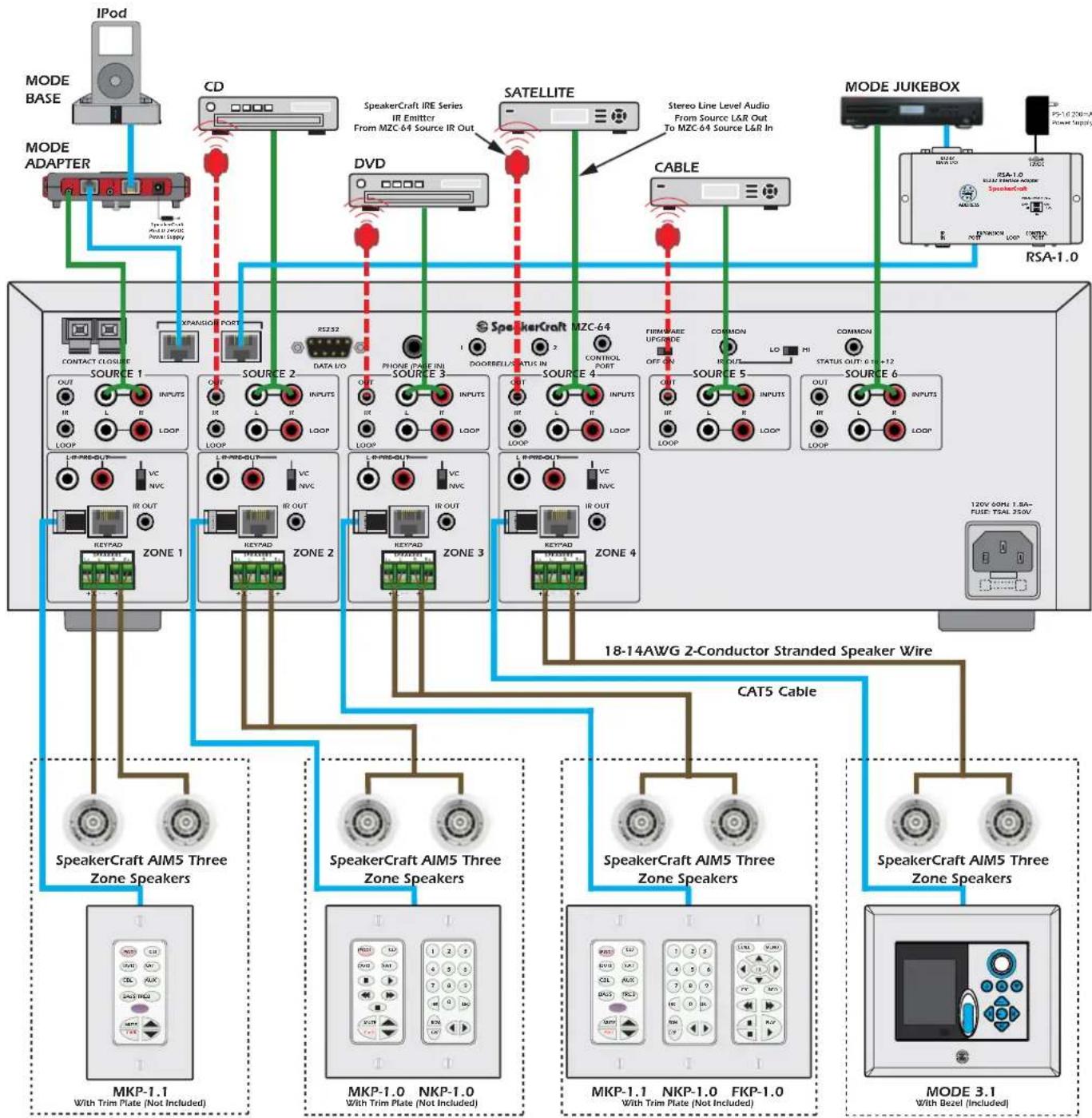
TYPICAL MZC-64 SYSTEM
flowchart
graph TD
    subgraph MODE_BASE
        A["IPod"] --> B["MODE ADAPTER"]
        C["CD"] --> D["SpeakerCraft IRE Series IR Emitter From MZC-64 Source IR Out"]
        D --> E["SATELLITE"]
        F["DVD"] --> G["CABLE"]
        H["SPEAKERCACT"] --> I["SpeakerCraft"]
    end

    subgraph MODE_JUKEBOX
        J["RSA-1.0"] --> K["MODE JUKEBOX"]
    end

    B --> L["CONTACT CLOUSE"]
    D --> M["EXPANSIO PORT"]
    E --> N["DATA LO"]
    G --> O["PHONE INPUT"]
    I --> P["FIRMWARE UPGRIDE"]
    K --> Q["COMMON"]
    L --> R["OUT"]
    M --> S["INPUTS"]
    N --> T["LOG"]
    O --> U["LOG"]
    P --> V["LOG"]
    Q --> W["LOG"]
    R --> X["LOOP"]
    S --> Y["LOOP"]
    T --> Z["LOOP"]
    U --> AA["LOOP"]
    V --> AB["LOOP"]
    W --> AC["LOOP"]
    X --> AD["LOOP"]
    Y --> AE["LOOP"]
    Z --> AF["LOOP"]
    AA --> AG["LOOP"]
    AB --> AH["LOOP"]
    AC --> AI["LOOP"]
    AD --> AJ["LOOP"]
    AE --> AK["LOOP"]
    AF --> AL["LOOP"]
    AG --> AM["LOOP"]
    AH --> AN["LOOP"]
    AI --> AO["LOOP"]
    AJ --> AP["LOOP"]
    AK --> AQ["LOOP"]
    L --> AR["PART SOURCE 1"]
    M --> AS["PART SOURCE 2"]
    N --> AT["PART SOURCE 3"]
    O --> AU["PART SOURCE 4"]
    P --> AV["PART SOURCE 5"]
    Q --> AW["PART SOURCE 6"]
    R --> AX["PART SOURCE 7"]
    S --> AY["PART SOURCE 8"]
    T --> AZ["PART SOURCE 9"]
    U --> BA["PART SOURCE 10"]
    V --> BB["PART SOURCE 11"]
    W --> BC["PART SOURCE 12"]
    X --> BD["PART SOURCE 13"]
    Y --> BE["PART SOURCE 14"]
    Z --> BF["PART SOURCE 15"]
    AA --> BG["PART SOURCE 16"]
    AB --> BH["PART SOURCE 17"]
    AC --> BI["PART SOURCE 18"]
    AD --> BJ["PART SOURCE 19"]
    AE --> BK["PART SOURCE 20"]
    AF --> BL["PART SOURCE 21"]
    AG --> BM["PART SOURCE 22"]
    AH --> BN["PART SOURCE 23"]
    AI --> BO["PART SOURCE 24"]
    AJ --> BP["PART SOURCE 25"]
    AK --> BQ["PART SOURCE 26"]
    AL --> BR["PART SOURCE 27"]
    AM --> BS["PART SOURCE 28"]
    AN --> BT["PART SOURCE 29"]
    AO --> BU["PART SOURCE 30"]
    AP --> BV["PART SOURCE 31"]

    subgraph MODE_3.1
        BW["MODE 3.1 With Bezel (Included)"]
        BX["MODE 3.1 With Trim Plate (Not Included)"]
        BY["MODE 3.1 With Trim Plate (Not Included)"]
        BZ["MODE 3.1 With Trim Plate (Not Included)"]
        CA["MODE 3.1 With Trim Plate (Not Included)"]
        BQ["MODE 3.1 With Trim Plate (Not Included)"]
        BZ["MODE 3.1 With Trim Plate (Not Included)"]
        BQ["MODE 3.1 With Trim Plate (Not Included)"]
        BZ["MODE 3.1 With Trim Plate (Not Included)"]
        BQ["MODE 3.1 With Trim Plate (Not Included)"]
        BQ["MODE 3.1 With Trim Plate (Not Included)"]
        BQ["MODE 3.1 With Trim Plate (Not Included)"]
        BQ["MODE 3.1 With Trim Plate (Not Included)"]
        BQ["MODE 3.1 With Trim Plate (Not Included)"]
        BQ["MODE 3.1 With Trim Plate (Not Included)"]
        BQ["MODE 60N 1.8A-FUSE TRAL 250V"]
        BQ["MODE 60N 1.8A-FUSE TRAL 250V"]
        BQ["MODE 60N 1.8A-FUSE TRAL 250V"]
        BQ["MODE 60N 1.8A-FUSE TRAL 250V"]
        BQ["MODE 60N 1.8A-FUSE TRAL 250V"]
        BQ["18-14AWG 2-Conductor Stranded Speaker Wire"]

    subgraph MODE_3.1
        BQ["MODE 3.1 With Bezel (Included)"]
        BQ["MODE 3.1 With Trim Plate (Not Included)"]
        BQ["MODE 3.1 With Trim Plate (Not Included)"]
        BQ["MODE 3.1 With Trim Plate (Not Included)"]
        BQ["MODE 3.1 With Trim Plate (Not Included)"]
        BQ["MODE 3.1 With Trim Plate (Not Included)"]
        BQ["MODE 3.1 With Trim Plate (Not Included)"]

    subgraph MODE_3.1
        BQ["MODE 3.1 With Bezel (Included)"]
        BQ["MODE 3.1 With Trim Plate (Not Included)"]
        BQ["MODE 3.1 With Trim Plate (Not Included)"]
        BQ["MODE 3.1 With Trim Plate (Not Included)"]
        BQ["MODE 3.1 With Trim Plate (Not Included)"]

    subgraph MODE_3.1
        BQ["MODE 3.1 With Bezel (Included)"]

    subgraph MODE_3.1
        BQ["MODE 3.1 With Trim Plate (Not Included)"]

        BW["MODE 3.1 With Bezel (Included)"]

        BX["MODE 3.1 With Trim Plate (Not Included)"]

        BY["MODE 3.1 With Trim Plate (Not Included)"]

        AZ["MODE 3.1 With Trim Plate (Not Included)"]

        BA["MODE 3.1 With Trim Plate (Not Included)"]

        BW["MODE 3.1 With Trim Plate (Not Included)"]

        BX["MODE 3.1 With Trim Plate (Not Included)"]

        BY["MODE 3.1 With Trim Plate (Not Included)"]

        AZ["MODE 3.1 With Trim Plate (Not Included)"]

        BA["MODE 3.1 With Trim Plate (Not Included)"]

        BW["MODE 3.1 With Trim Plate (Not Included)"]

        BX["MODE 3.1 With Trim Plate (Not Included)"]

        BY["MODE 3.1With Trim Plate (Not Included)"]

        AZ["MODE 3.1With Trim Plate (Not Included)"]

        BA["MODE 3.1With Trim Plate (Not Included)"]

        BW["MODE 3.1With Trim Plate (Not Included)"]

        BX["MODE 3.1With Trim Plate (Not Included)"]

        BY["MODE 3.1With Trim Plate (Not Included)"]

        AZ["MODE 3.1With Trim Plate (Not Included)"]

        BW["MODE 3.1With Trim Plate (Not Included)"]

        BX["MODE 3.1With Trim Plate (Not Included)"]

        BY["MODE 3.1With Trim Plate (Not Included)"]

        AZ["MODE 3.1With Trim Plate (Not Included)"]

        BW["MODE 3.1With Trim Plate (Not Included)"]

        BX["MODE 3.1With Trim Plate(Not Included)"]

        BY["MODE 3.1With Trim Plate(Not Included)"]

        AZ["MODE 3.1With Trim Plate(Not Included)"]

        BW["MODE 3.1With Trim Plate(Not Included)"]

        BX["MODE 3.1With Trim Plate(Not Included)"]

        BY["MODE 3.1With Trim Plate(Not Included)"]

        AZ["MODE 3.1With Trim Plate(Not Included)"]

        BW["MODE 3.1With Trim Plate(Not Included)"]

        BX["MODE 3.1With Trim Plate(Not Included)"]

        BY["MODEMISATIIMAX Three Zone Speakers"]

        BWMOMMOMMOMMOMMOMMOMMOMMOMMOMMOMMOMMOMMOMMOMMOMMOMMOMMOMMOMMOMMOMMOMMOMMOMMOMMOMMOMMOMMOMMOMMOMMOMMOMMOMMOMMOMMOMMOMMOMMOMMOMMOMMOMMOMMOMMOMMOMMOMMOMMOMMAM
    end

    style MODE_3.1 fill:#f9f,stroke:#333,stroke-width:2px
    style MODE_3.1 fill:#ccf,stroke:#333,stroke-width:2px
    style MODE_3.1 fill:#cfc,stroke:#333,stroke-width:2px
    style MODE_3.1 fill:#fcc,stroke:#333,stroke-width:2px
</details>
ZONE 1 ZONE 2 ZONE 3 ZONE 4
Figure 10
Typical MZC-64 System
<h1 id="system-planning-and-installation">SYSTEM PLANNING AND INSTALLATION</h1>
<h1 id="system-planning">SYSTEM PLANNING</h1>
With all of the flexibility and options of a MZC-64 System, careful planning can save time and money for both the installer and homeowner. A few EZ steps can help in managing this process.
1. KNOW THE PRODUCT AND ALL OF ITS CAPABILITIES — This will help in making suggestions to the homeowner for incorporating features they may want. It will also help in being able to combat feature capabilities, or inadequacies, of a competitive product that another Installation Company may be proposing.
2. KNOW THE HOMEOWNER — Spend some time in the home if possible, and get a feel for how the prospective client is going to want to use the system. If the home is in the planning stage, be sure to get involved with the architect to assure proper allocation of space for system components, ventilation and access to the system for service (a closet with rear access to the system connections is ideal whenever possible).
3. DOCUMENT EVERYTHING — When discussing the system with the prospective client, write down all of their 'wants' in terms of how they want the system to work. Do they want doorbell paging? Do they have lots of parties and want to 'group' zones in common areas? Will they need an external high-powered amplifier for the patio/pool area?
Write everything down and review it with the homeowner to define specific system features and functions. Suggest options for future upgrading or expansion of the system, such as additional wire infrastructure, for adding rooms to the system long after the walls have been sealed. Use the results of the review to create a formal proposal.
4. LEAVE PRODUCT INFORMATION — Leave the client with Brochures for the MZC-64, SpeakerCraft Speakers, Amplifiers and Accessories that will be specified in the proposal. (Packaging it all in a nice folder or binder is a nice touch.) Confirm a date to review the formal proposal.
5. CONTRACT THE JOB — Get back to the prospective client with a professional, formal proposal. (There are some good system planning and proposal software packages that can really help manage this whole process.) Review their 'wants' and show how they have been implemented in the overall system design. Inform the homeowner as to how the installation will be done. Phase 1, pull wire. Phase 2, install speakers and components. Phase 3, system programming and tweaking. (Tying payments to the different installation phases is also something to consider. Spreading the payments can help defuse potential sticker shock for the homeowner and also help manage cash flow for the Installation Company.) If all is acceptable to the homeowner, have them sign the proposal as a formal contract and set a start date for work to begin. (Having the homeowner sign the proposal as a contract can help avoid problems during installation in that the system and work to be done is defined. Anything not defined in the contract is extra.)
6. DOCUMENT THE SYSTEM FOR INSTALLATION — If using one of the planning and proposal software packages available from third parties, this part of the process will already be done. If not, carefully document the system for whole-house wiring. Show all runs of CAT-5 for control, coax for video, two-pair 18-14AWG stranded for speakers and additional wires for doorbell/paging, and anything else in the system that needs to have wire pulled through the walls. Don't leave anything out. The person pulling the wire isn't necessarily the same person that sold the system, so if the system hasn't been properly documented, critical feature wire components could be left out.
Detail what components will be installed in each room, and where they will be installed, including the control system, speakers, TV/Video Display and any other sub-system interfaces by room, by component, by brand and by model. Be sure the person pulling the wire has this information to cross reference the wires pulled and to where.
7. DOCUMENT SYSTEM FUNCTIONALITY — Document all system functions by system, by zone, by source and any special features that have been included. Be sure to include functions such as how the system turns on when the first source is selected, and how it turns off when the last zone shuts down. Include all special functions such as switch closures for lifts and screens and EPR-1.0 mute commands for zones with multi-channel amps for sub-zone expansion. Include Tuner preset preferences if applicable. Include Paging functions. All system functions should be detailed. The person doing the system programming isn't necessarily the same person who sold the system or pulled the wire. Be sure everyone involved in the installation and setup knows what the system is and how it is supposed to work.
8. ACQUIRE ALL SYSTEM COMPONENTS — Set up the system, and program and test all functions before taking the electronics to the job site. This can save valuable time in assuring that all system components work and the system is functioning as designed. Connecting and testing the system prior to installation will also help assure that all parts and pieces that will go into the system are in hand, so time is spent on the job site and not running around town shopping for parts or not being able to finish the installation while waiting for an air shipment of a ten dollar part.
9. HEAD-END CONSIDERATIONS — The system head-end should be in a convenient, central location that provides easy access for the user, to be able to load discs, video tapes etc. The location should also be accessible for service and ideally would have either have rear access to the system connections or a pull-out rack that allows access to system connections. All system wire runs should terminate at the head-end. There should be sufficient mounting space for all system components and the wires and cables that connect them. Leave plenty of room for airflow for proper ventilation or system components could be damaged. Too tight of a space that does not leave room for system wiring or a poorly dressed system can cause thermal problems. Wires jumbled in around system components can act as an insulator or block free airflow which can damage the components from overheating. Incorporate a proper ventilation system using cooling fans (SpeakerCraft ESC-1) for systems with external amplifiers or other components that generate excess heat. When possible, leave extra space for future expansion of the system for additional zone and source components.
10. ZONE CONSIDERATIONS — Identify all room components and their locations. Typically, a keypad would be mounted near the entry to a room. If the room orientation of where the TV/Monitor and speakers are located leaves the keypad behind the user, an additional IR receiver on the same wall as the TV and speakers will help make controlling the system more user friendly. Be sure to include an appropriate wire run for the IR receiver. Additional wire runs for controlling lifts, screens and drapes should also be considered. Try to avoid mounting keypads and IR receivers in locations that will be exposed to direct sunlight. Leave extra wire at keypad and in-wall speaker locations so these components can be easily removed without pulling on wires and possibly have them fall down inside the wall, should service be necessary.
<h1 id="system-installation">SYSTEM INSTALLATION</h1>
<h1 id="wiring">WIRING</h1>
Once the system has been defined and the contract signed, work can begin. The first part of the system to be installed is the wiring infrastructure. With all of the flexibility and options of a MZC-64 System, maintaining clear, accurate documentation of the location (the house) and the system will help in managing a smooth installation. Always be sure to pull and test the wires needed for the system as specified, and always consider pulling extra wire for fall-back in the event something gets damaged during drywall installation. Beyond that, pulling additional wire to rooms not specified in the system can help down the road, should the homeowner decide to add rooms to the system at a later date, or increase flexibility within already active rooms.
There are certain types of wire that are default requirements and there are others that are used for the system optional features.
<h1 id="keypads">KEYPADS</h1>
SpeakerCraft EZ-Pads have seven-position spring clip terminals for wire connections. Five of these terminals are used for connection to the MZC-64 Keypad Terminals. CAT-5 can be used with or without RJ45 connectors on the keypad end, but must be terminated with a RJ45 plug on the MZC end. Be sure to follow the color coding pin-outs for the keypad connections and use the pin-out for the RJ45 connection to the MZC as shown in section: EZ-Pad Configuration. Standard wire can also be used for retro-fit installations provided there are at least 5 conductors available. Use of SpeakerCraft RJA-1.1 RJ45 to Wire Pin Adaptors is recommended for EZ-Pad connections. See: IMKP Installation Instructions and MODE 3.1 Installation Instructions for more information regarding connections for those models.
<h1 id="cat-5-with-rj45-connectors">CAT-5 WITH RJ45 CONNECTORS</h1>
Requirement - Pull home-runs of CAT-5 from each Keypad location to the System Head-End.
MAXIMUM LENGTH: 1000' (305m) EZ-Pad/IMKP; 500' (152m) MODE 3.1.
Installation - Terminate the CAT-5 with RJ45 connectors on both ends utilizing the RJ45 pin-out shown in section: EZ-Pad Configuration. Be sure the terminations are identical on both ends, creating a pass-through configuration. Connect the CAT-5 cable to EZ-Pads using SpeakerCraft RJA-1.1 RJ45-to-Wire Pin Adapters. Insert the RJA-1.1 pins into the keypad's EZ-Connect Terminals and snap the levers in place. RJA1.1's can be used at both the keypad and KCM-1.0 ends, if desired. Be sure RJA1.1 pin orientation is correct on both ends prior to powering up the system. Not applicable for IMKP or MODE 3.1.
<h1 id="cat-5-without-rj45-connectors-ez-padimkpmode-31-ends-only">CAT-5 WITHOUT RJ45 CONNECTORS (EZ-Pad/IMKP/MODE 3.1 Ends Only)</h1>
Requirement - Pull home-runs of CAT-5 from each EZ-Pad location to the System Head-End.
MAXIMUM LENGTH: 1000' (305m) EZ-Pad/IMKP; 500' (152m) MODE 3.1.
Installation - Strip away approximately 2" of the CAT-5 jacket and separate the individual conductors. Strip approximately ¼ inch of the individual conductors to be used for connection to the EZ-Pads/IMKPs. Twist the stripped ends so there are no loose strands that can cause shorts. Secure the ends to the EZ-Pad/IMKP terminals. Maintain proper polarity. For IMKP, strip approximately 6mm from each conductor and secure to the appropriate screw-down terminal. For MODE 3.1, strip ¼ inch from each conductor and secure to the proper terminal with a punch-down tool. Terminate MZC ends as described above in section: CAT-5 WITH RJ45 CONNECTORS.
<h1 id="standard-wire-recommended-for-retro-fit-only">STANDARD WIRE (Recommended for Retro-fit Only)</h1>
Requirement - Home-runs of 28-14AWG stranded, non-sheilded wire with at least 5 conductors to the System Head-End.
MAXIMUM LENGTH: 1000' (305m) EZ-Pad/IMKP; 500' (152m) MODE 3.1.
Installation - Strip away approximately 2" of the wire jacket and separate the individual conductors. Strip approximately ¼ inch on both ends of the individual conductors to be used for connection to the EZ-Pads/IMKPs/MODE 3.1 and MZC-64. Twist the stripped ends so there are no loose strands that can cause shorts. Secure the ends to the proper keypad terminals. Maintain proper polarity. Unused leads can be connected in parallel, one, with each of the +12V, GND and IR/IO leads, for better IR performance when using lighter gauge wire on long runs. Adapt the stripped ends on the MZC
end to a RJ45/CAT-5 cable pigtail utilizing the RJ45 pin-out as shown in section: EZ-Pad Configuration. Maintain proper polarity and double check connections prior to powering up the system. Improper connections can cause damage to the keypads, MZC or both.
<h1 id="speakers">SPEAKERS</h1>
Requirement - Pull home runs of 18-14AWG two-conductor quality stranded speaker wire from all speaker locations to the System Head-End.
MAXIMUM LENGTH: 18AWG up to 50'; 16AWG up to 200'; 14AWG up to 1000'.
Installation - Strip approximately 14 inch off each end of each conductor and twist the stripped ends so there are no loose strands that can cause shorts. On the Head-End side, carefully slide the individual conductors into the appropriate L+,L-/R-,R+ speaker terminals on the removable screw down connectors that plug into the MZC-64 Zone Speaker OUT Terminals. Terminate the speaker ends as appropriate for the given speakers. Maintain proper polarity.
WARNING: The power amplifiers in the MZC-64 use Bridged (BTL) outputs. Speaker connections must be completely separate for each channel and have NO common ground connections through any connected Speaker Selectors, VCs, Test Equipment, etc. Failure to observe this may cause damage and void the warranty.
<h1 id="contact-closures">CONTACT CLOSURES</h1>
Requirement - Pull 28-14AWG two-conductor stranded wire from any location utilizing a contact closure from the MZC-64 to the System Head -End.
MAXIMUM LENGTH: Will vary with application.
Installation - On the Head-End side, strip approximately 14 " off each end of each conductor and twist the stripped ends so there are no loose strands that can cause shorts. Carefully slide the individual conductors into the appropriate Contact Closure Terminal pair on the MZC-64 Rear Panel. Terminate the device end as appropriate. POLARITY: MZC end not critical.
<h1 id="expansion-portloop">EXPANSION PORT/LOOP</h1>
Requirement - CAT-5 cable terminated with RJ45 connectors, pass-through configuration (pin to pin).
MAXIMUM LENGTH: 1000'
Installation - When using multiple MZC-64's, connect CAT-5 cables terminated with RJ45 connectors to MZC-64 Port/Loop terminals in expanded systems. See section: Expanded Systems for additional information.
When using MODE Adapters, pull CAT-5 from the MZC to where the MODE Adapter(s) will be installed. For installations where the Adapter will be at the system head-end, a CAT-5 patch cable can be used at time of installation and hook-up. For installations where the Adapter will be in a remote location, pull CAT-5 and terminate with a proper wall plate with a pass-through (pin to pin) configuration. MAXIMUM LENGTH (for MODE Adapter): 100'. NOTE: This connection requires configuration in EZ-Tools. See: MODE 3.1 Installation Instructions for additional information.
When using RSA-1.0(s) pull CAT-5 from the MZC to where the RSA-1.0(s) will be installed. For installations where the RSA will be at the system head-end, a CAT-5 patch cable can be used at time of installation and hook-up. For installations where the Adapter will be in a remote location, pull CAT-5 and terminate with a proper wall plate with a pass-through (pin to pin) configuration. MAXIMUM LENGTH (for RSA-1.0): 1000'. NOTE: This connection requires configuration in EZ-Tools. See: RSA-1.0 Installation Instructions for additional information.
<h1 id="rs232">RS232</h1>
Requirement - Use a quality, pre-made Serial Cable terminated with DB9 connectors, terminated as appropriate for device being controlled.
MAXIMUM LENGTH: 50'
Installation - Connect one end of the Serial cable to the RS232 DATA I/O Port on the MZC-64 Rear panel and the other end to the device being controlled via RS232. NOTE: This connection requires configuration in EZ-Tools.
<h1 id="control-port">CONTROL PORT</h1>
Used for system programming and firmware updates. See: EZ-Tools MZC Programming Instructions for additional information.
<h1 id="phone-page-in">PHONE PAGE IN</h1>
Requirement - Use a quality, pre-made audio cable terminated with RCA connectors for runs under 15'. Pull quality, shielded audio cable from the paging device to the System Head-End for runs up to 200'.
MAXIMUM LENGTH: 200'
NOTE: Some Telephone Control Panels can produce sufficient levels of RF radiation to interfere with MZC-64 performance. It is recommended that Telephone Panels be located at least 15-20 feet from an MZC-64 to avoid interference.
Installation - Connect one end of the pre-made wire to the paging device line level audio out and the other to the PHONE PAGE IN jack on the MZC-64 Rear Panel. Terminate the shielded audio cable with an RCA connector at the System Head-End. Terminate the paging device end as appropriate. Maintain proper polarity. RCA CONNECTOR POLARITY: PIN=SIG; SLEEVE=GND.
<h1 id="doorbellstatus-in">DOORBELL/STATUS IN</h1>
Requirement - Pull 28-22AWG two-conductor stranded wire from the doorbell or sensed device location to the System Head-End.
MAXIMUM LENGTH: Will vary. 500' typical, up to 2000' with some devices.
Installation - Terminate the 28-22AWG two-conductor wire with a 3.5mm mini plug at the System Head-End for connection to one of the two Doorbell/Status IN jacks on the MZC-64 Rear Panel. Terminate the Doorbell/sensed device end as appropriate. MINI PLUG POLARITY: TIP=+12V; SLEEVE=GND.
<h1 id="common-ir-out">COMMON IR OUT</h1>
Requirement - Use a SpeakerCraft standard emitter (IRE-1.0, 2.0, 3.0, 4.0) when the Common IR OUT Switch is set in the LO position. Use a SpeakerCraft high power emitter (IRE-5.0 Blaster) when the Common IR OUT Switch is set in the HI position. Pull 28-18AWG two-conductor stranded wire from the location requiring System Common IR Control to the System Head-End to extend the emitter wire as required.
MAXIMUM LENGTH: 1000'
Installation - Connect an emitter to the Common IR OUT on MZC-64 Rear Panel and set the HI/LO switch as appropriate. Attach the emitter over the IR eye on the device to be controlled. When extending the emitter wire, terminate the 28-18AWG two-conductor wire with a 3.5mm mini plug at the System Head-End. Terminate the other end for System Common IR Control as appropriate. MINI PLUG POLARITY: TIP=SIG; SLEEVE=GND.
<h1 id="common-status-out">COMMON STATUS OUT</h1>
Requirement - Pull 28-18AWG two-conductor stranded wire from the device to be controlled to the System Head-End. MAXIMUM LENGTH: 1000'
Installation - Terminate the 28-18AWG two-conductor wire with a 3.5mm mini plug at the System Head-End for connection to the Common Status OUT jack on the MZC-64 Rear Panel. Terminate the controlled device end as appropriate. MINI PLUG POLARITY: TIP=+12V; SLEEVE=GND.
<h1 id="source-ir-out">SOURCE IR OUT</h1>
Requirement - Use SpeakerCraft standard IR emitters (IRE-1.0, 2.0, 3.0, 4.0).
Installation - Attach emitter to Source Component. Connect emitter mini plug to the appropriate Source IR OUT.
<h1 id="source-ir-loop">SOURCE IR LOOP</h1>
Requirement - Use pre-made 3.5mm mini to mini plug cables.
Installation - Connect SOURCE IR OUT on one MZC-64 to the same source number SOURCE IR LOOP on the next MZC-64 when using multiple MZC-64s in expanded systems. i.e. MZC Slave 2 SOURCE 1 IR OUT to MZC Slave 1 SOURCE 1 LOOP, MZC Slave 1 SOURCE 1 IR OUT to MZC Master SOURCE 1 LOOP, MZC Master SOURCE 1 IR OUT to an emitter for Source 1 IR control. See section: Expanded Systems for additional information.
<h1 id="source-audio-input">SOURCE AUDIO INPUT</h1>
Requirement - Use quality, RCA to RCA stereo audio cables with gold ends.
Installation - Connect one end to Source L & R line-level AUDIO OUT, and connect the other end to the appropriate Source L & R line-level AUDIO INPUT on the MZC-64 Rear Panel.
<h1 id="source-audio-loop">SOURCE AUDIO LOOP</h1>
Requirement - Use quality, RCA to RCA stereo audio cables with gold ends.
Installation - Connect SOURCE L & R line-level AUDIO LOOP on one MZC-64 to the same source number SOURCE L & R line-level AUDIO INPUT on the next MZC-64 when using multiple MZC-64s in expanded systems. i.e. MZC-64 MASTER SOURCE 1 L & R line-level AUDIO LOOP to MZC-64 SLAVE 1, SOURCE 1, L & R line-level AUDIO INPUT, MZC SLAVE 1, SOURCE 1, L & R line-level AUDIO LOOP to MZC-64 SLAVE 2, SOURCE 1, L & R line-level AUDIO INPUT. See Section: Expanded Systems for additional information.
<h1 id="zone-pre-out">ZONE PRE-OUT</h1>
Requirement - Use quality, RCA to RCA stereo audio cables with gold ends.
Installation - Connect one end to Zone L & R line-level PRE-OUT and connect the other end to the appropriate L & R line-level AUDIO INPUTS on an external amplifier. (Set VC/NVC Switch for Volume Control/No Volume Control as appropriate.) See Section: External Amplifiers for additional information.
<h1 id="zone-ir-out">ZONE IR OUT</h1>
Requirement - Use SpeakerCraft standard IR emitters (IRE-1.0, 2.0, 3.0, 4.0).
Installation - Attach emitter to Zone Source Component. Connect emitter mini plug to the appropriate Zone IR OUT.
<h1 id="ez-pad-configuration">EZ-PAD CONFIGURATION</h1>
1. As received from the factory, the MKP-1.1 EZ-Pads have a preinstalled set of buttons that may not match the system being installed. To change the source and function button arrangement, release the tabs, Figure 11, and remove the decorator insert panel, exposing the key buttons. (Figure 12.) IMKP and MODE 3.1 buttons can also be changed. See: IMKP Installation Instructions and MODE 3.1 Installation Instructions for additional information.

<details>
<summary>text_image</summary>
Press tabs here
at both ends
to release
Decorator Insert Panel
</details>
Figure 11 Release Tab
2. Starting with the Zone 1 MKP-1.1 (Master Keypad), and using the extra buttons supplied, if needed, move and place the source and function buttons in an arrangement matching the system being installed. (Refer to Figure 13) When finished, replace the decorator insert panel over the buttons, being careful to see that the buttons align correctly with the panel openings. Press the panel down until the tabs "snap" into place.
3. Repeat these steps for each of the other zone Master Keypads. Note that each zone can have its own unique configuration, however, it is best to keep them as similar as possible to simplify system programming and operation.
4. Repeat steps 1-3 to configure the buttons on the Numeric and Function keypads (not included) as needed.

<details>
<summary>text_image</summary>
Decorator Insert Panel
Tab Buttons
Membrane keys
</details>
Figure 12
Remove Decorator Insert Panel

<details>
<summary>natural_image</summary>
Close-up of hands holding a small electronic component with multiple labeled pins (no readable text or symbols)
</details>
Figure 13
Moving and Placing Buttons
NOTE: The Numeric and Function keypads will not work on their own. They must be connected to a Master Keypad using the 3-Connector Ribbon Cable included with each NKP-1.0 and FKP-1.0. The cable is symmetrical so it can be connected with the red striped side up or down, to best fit the configuration. Figure 14 shows it connected so that the MKP Master Keypad will be to the right of the NPK Numeric and FKP Function keypads when mounted, whereas Figure 15 places the MKP to the left.

<details>
<summary>natural_image</summary>
Three electronic components labeled NKP1.0, FKP1.0, and SpeakerCraft with connector pins and a ribbon (no readable text beyond labels)
</details>
Figure 14
Ribbon Cable – MKP Right

<details>
<summary>text_image</summary>
FKP-1.0
J-Box EZPad
- Function -
SpeakerCraft
NKP-1.0
J-Box EZPad
- Numeric -
SpeakerCraft
MKP-1.0
J-Box EZ Pad
- Master
+ I/O
+ 2V
+ 3V
+ 4V
+ 5V
+ 6V
+ 7V
+ 8V
+ 9V
+ 10V
+ 11V
+ 12V
+ 13V
+ 14V
+ 15V
+ 16V
+ 17V
+ 18V
+ 19V
+ 20V
+ 21V
+ 22V
+ 23V
+ 24V
+ 25V
+ 26V
+ 27V
+ 28V
+ 29V
+ 30V
+ 31V
+ 32V
+ 33V
+ 34V
+ 35V
+ 36V
+ 37V
+ 38V
+ 39V
+ 40V
+ 41V
+ 42V
+ 43V
+ 44V
+ 45V
+ 46V
+ 47V
+ 48V
+ 49V
+ 50V
+ 51V
+ 52V
+ 53V
+ 54V
+ 55V
+ 56V
+ 57V
+ 58V
+ 59V
+ 60V
+ 61V
+ 62V
+ 63V
+ 64V
+ 65V
+ 66V
+ 67V
+ 68V
+ 69V
+ 70V
+ 71V
+ 72V
+ 73V
+ 74V
+ 75V
+ 76V
+ 77V
+ 78V
+ 79V
+ 80V
+ 81V
+ 82V
+ 83V
+ 84V
+ 85V
+ 86V
+ 87V
+ 88V
+ 89V
+ 90V
+ 91V
+ 92V
+ 93V
+ 94V
+ 95V
+ 96V
+ 97V
+ 98V
+ 99V
</details>
Figure 15
Ribbon Cable – MKP Left
5. When connecting keypads to the MZC-64 as shown in Figure 16, be sure to connect the various colored CAT-5 leads to the correct Terminals on each end. Use the same colors scheme for all zones to help reduce errors.

<details>
<summary>text_image</summary>
MKP-1.1
J-Box EZ-Pad w/IRC
-Master-
SpeakerCraft
+RELAY
-RELAY
+12V
IR I/O
GND
485 A
485 B
Rear View
Orange Pair
Blue Pair
Green Pair
Brown-White
Brown
Use Twisted Pair
for 485A & 485B
KEYPAD CAT5 RJ45
GND Green PIN 1
+12V Orange PIN 2
485A Brown PIN 3
IR I/O Blue PIN 4
IR I/O Blue/White PIN 5
485B Brown/White PIN 6
+12V Orange/
White PIN 7
GND Green/White PIN 8
Inter-room
Twisted Pair
Cat. 5 Cable
1000' (305m) Max.
MZC-64
EZ-Pad
Connector
PRE-OUT
VC
NVC
IROUT
ZONE 2
</details>
Figure 16
Using CAT-5 Cable to Connect MKP Keypads to MZC-64
CAT-5 WITHOUT RJ45 CONNECTORS — Connect Keypads to MZC-64 as shown above. Be sure to maintain consistent color code when making connections. Maximum recommended lead length with CAT-5 cable is 1000' (305m).
CAT-5 WITH RJ45 CONNECTORS — When using RJ45 connectors, connect the CAT-5 cable to the keypads using SpeakerCraft model RJA-1.1 RJ45-to-Wire Pin Adapters. (Refer to Figures 17 and 18) Insert the RJA-1.1 pins into the keypad's EZ-Connect Terminals and snap the levers in place. Be sure RJA-1.1 pin orientation is correct prior to powering up the system. CAT-5 cable should be configured in a pass-through (pin to pin) termination. See table above.

<details>
<summary>text_image</summary>
EYPAD EXPANSION
+RELAY
-RELAY
+12V
IR/IO
GND
485
485
MKP
ADDRESS
</details>
Figure 17
RJA-1.1 Adapter

<details>
<summary>natural_image</summary>
Close-up of a mechanical component with metallic pins and a coiled cable (no visible text or symbols)
</details>
Figure 18
RJA-1.1 attached to Keypad and CAT-5
<h1 id="installation">INSTALLATION</h1>
<h1 id="head-end">HEAD-END</h1>
The MZC-64, external source components, and additional amplifiers will typically be installed at the System Head-End. They can be mounted on shelves in a wall unit, entertainment center or closet, or rack mounted in a standard 19" rack mount system. Source components such as DVD/CD players and VCR's should be installed so the user has easy access for loading discs and tapes.
Though heavy, the MZC-64 (and additional amplifiers if used) should be mounted at the top of the equipment rack so heat generated by the controller will not affect the other system components. This will also allow cooler air to rise up through the equipment rack with the hottest devices exhausting out the top. Use cooling fans such as the SpeakerCraft ESC-1.0 rack cooling system, to push/pull air through the equipment rack if temperatures exceed the specifications of any of the system or source components. Properly exhaust hot air into an attic space or outside the structure. (Be aware of and comply with any building codes that may apply to ventilation.)
Always leave adequate space between system and source components for airflow. Failure to do so can cause damage to the components from overheating. Never block the vent holes on the top or bottom of the MZC-64. Blocking the vent holes will cause the controller to overheat. Never remove the MZC-64 Controller's feet when shelf mounting. This will block the vent holes on the bottom of the unit and will cause the controller to overheat. When using multiple MZC-64s in a system DO NOT stack the MZC-64 Controllers directly on top of each other. Leave at least 3-4" between controllers, and if rack mounting, use at least one, double rack-space vent panel between controllers to assure proper airflow.
<h1 id="connections-head-end">CONNECTIONS - HEAD END</h1>
This section provides information for connections to a single MZC-64 Controller. See Section: EXPANDED SYSTEMS for information on connections to multiple MZC-64's in expanded systems. All system and source components should be installed before making any connections. To prevent electrical shock and possible damage, be sure all components are disconnected from AC power while making connections.
<h1 id="keypads-2">KEYPADS</h1>
1. Connect each keypad run to the appropriate Keypad Terminal on the MZC-64. Be sure CAT-5 cable and RJ45 connectors are properly configured as shown in Figure 16. See Sections: Wiring and EZ-Pad Configuration for additional information.
<h1 id="external-source-components">EXTERNAL SOURCE COMPONENTS</h1>
<h1 id="audio">AUDIO</h1>
1. Connect the L & R line-level audio OUT of each external source component to the appropriate L & R line-level audio Source In on the MZC-64 Rear Panel. Use quality stereo audio RCA-RCA cables with gold connectors.
<h1 id="emitters-source">EMITTERS (SOURCE)</h1>
1. Carefully attach a SpeakerCraft IR Emitter (Models: IRE-0.5, 1.0, 2.0, 3.0, 4.0) over the IR eye on the front panel of each external source component to be controlled via infrared.
2. Carefully pull the emitter wire to the back of the MZC-64. Do not block accesses for discs and tapes. Do not pinch emitter wires between components.
3. Connect the 3.5mm mini plug to the appropriate Source IR OUT.
<h1 id="speakers-2">SPEAKERS</h1>
1. Connect each Zone speaker run to the appropriate Zone Speaker Terminal using the included removable screw down connectors.
2. Strip approximately 14 inch of each lead and twist the stripped ends so there are no loose strands that can cause shorts.
3. Carefully slide the individual conductors into the appropriate L+,L-/R-,R+ speaker terminals on the removable screw down connector.
4. Visually check for loose ends. Lightly pull the wire to confirm connection.
5. Plug connector into the appropriate Zone Speaker Terminal.
<h1 id="paging">PAGING</h1>
<h1 id="phone-page-in-2">PHONE (PAGE IN)</h1>
1. Connect the audio line-level OUT of an appropriately featured telephone system, doorbell mic or other audio source to the PHONE (PAGE IN) jack on the MZC-64 Rear Panel. If the telephone system main unit is in close proximity to the MZC-64, use a quality RCA to RCA audio cable for connections up to 50'. For longer runs pull quality 16AWG two-conductor audio cable and terminate appropriately.
NOTE: The Phone Paging input requires a trigger voltage to one of the Doorbell/Status IN jacks to be activated.
<h1 id="doorbellstatus-in-12">DOORBELL/STATUS IN (1&2)</h1>
1. Connect a 3-30V AC or DC trigger voltage from a telephone system, sensing device or other controlled voltage output device to either Doorbell/Status Input 1 or 2 using a 3.5mm mini plug to activate the phone and page input. This input can also be used for sensing the ON/OFF condition of external devices or trigger other system events.
NOTE: The Doorbell/Status Inputs will not function without proper configuration in EZ-Tools.
<h1 id="contact-closures-2">CONTACT CLOSURES</h1>
1. Connect two stripped wires from a device such as a screen, lift, drapes, switched outlet etc, that requires a switch closure to activate.
2. Strip approximately 14 inch of each lead and twist the stripped ends so there are no loose strands that can cause shorts.
3. Carefully slide each of the individual conductors into one of the spring clip terminals.
4. Visually check for loose ends. Lightly pull the wire to confirm connection.
NOTE 1: Some devices may provide voltage on one terminal and only require a switch closure for activation, while others may require adding an appropriately rated power supply. If external voltage is required, connect an appropriately rated power supply in series with one of the contact closure terminal pair. Check the device being activated to determine if it requires AC or DC voltage and if polarity is critical for operation. Polarity is not critical at the MZC-64 Contact Closure end.
NOTE 2: The Contact Closure will not function without proper configuration in EZ-Tools.
NOTE 3: Be sure controlled device does not exceed the 30V 2A rating of the Contact Closure.
<h1 id="expansion">EXPANSION</h1>
1. Connect to Port and Loop Terminals on additional MZC-64 Controllers in expanded systems, using CAT-5 cables terminated with RJ45 connectors. See Section: Expanded Systems for additional information.
<h1 id="rs232-data-io">RS232 DATA I/O</h1>
1. Connect one end of a Serial cable to the RS232 Data I/O Port on the MZC-64 Rear panel and the other end to the device being controlled via RS232. NOTE: This connection requires configuration in EZ-Tools.
<h1 id="control-port-2">CONTROL PORT</h1>
1. Connect the Serial Port on a PC running EZ-Tools to the MZC-64 Control Port using a SpeakerCraft 3.5mm Plug Transfer Cable when programming the system or incorporating Firmware Upgrades.
NOTE 1: If a Serial Port is not available on the PC, connect the 3.5mm Plug Transfer Cable to the USB/Serial Adaptor Cable, (sold separately). Connect one end to a USB port on the PC and the other end of the assembled cable to the Control Port on the MZC-64.
NOTE 2: Use of the USB/Serial Adaptor Cable requires loading the USB/Serial Driver to the PC running EZ-Tools. The USB/Serial Driver is embedded as an option in the EZ-Tools Setup, downloadable from www.speakercraft.com. See: EZ-Tools MZC Programming Instructions for additional information.
<h1 id="common-ir-out-2">COMMON IR OUT</h1>
1. Connect to a SpeakerCraft Terminator Block, IR emitter or IR Blaster for control of common system devices other than the common external source components.
<h1 id="terminator-block">TERMINATOR BLOCK</h1>
1. Connect the IR IN and GND terminals on a SpeakerCraft AT-1.0 Terminator to the MZC-64 Common IR OUT jack
using a 3.5mm mini plug. POLARITY: TIP=SIG; SLEEVE=GND.
2. Set the Common IR Out HI/LO Switch on the MZC-64 to LO.
3. Connect a SpeakerCraft PS 2.0 Power Supply to the AT-1.0. (Connect to AC only after all system connections have been made and system is ready for use.)
4. Connect SpeakerCraft IR Emitters (IRE 0.5, 1.0, 2.0, 3.0, 4.0) and properly attach to the devices to be controlled.
<h1 id="ir-emitter">IR EMITTER</h1>
1. Carefully attach a SpeakerCraft IR Emitter (Models: IRE-0.5, 1.0, 2.0, 3.0, 4.0) over the IR eye on the front panel of common source component to be controlled via infrared.
2. Carefully pull the emitter wire to the back of the MZC-64. Do not block accesses for discs and tapes.
3. Connect the 3.5mm mini plug to the Common IR Out jack.
4. Set the HI/LO Switch to LO.
<h1 id="ir-blaster">IR BLASTER</h1>
1. Appropriately position a SpeakerCraft IR Blaster (Model: IRE-5.0) to saturate an area of common source components to be controlled via infrared.
NOTE: This application is not recommended if there is any duplication of source components (multiple same-brand, same-model DVD players or Satellite Receivers, etc) or zone-specific devices that could be affected by Blaster output.
2. Carefully pull the Blaster wire to the back of the MZC-64. Do not block accesses for discs and tapes.
3. Connect the 3.5mm mini plug to the Common IR Out jack.
4. Set the HI/LO Switch to HI.
<h1 id="common-status-out-2">COMMON STATUS OUT</h1>
1. Connect to the 12V or Control In terminal on a device such as a switched power strip, that is to be activated when any zone in the system is ON.
2. Terminate and connect to the controlled device as appropriate.
3. Connect to the Common Status OUT using a 3.5mm mini plug. POLARITY: TIP=+12VDC; SLEEVE=GND.
<h1 id="zone-pre-out-2">ZONE PRE-OUT</h1>
1. Connect to the L&R line-level audio IN on an external high-power or multi-channel amplifier as needed for large rooms or sub-zone expansion. Different applications require proper setting of the associated VC/NVC Switch. Some applications will utilize the on-board zone pre-amp volume control (VC - variable, zone volume controlled by keypads or IR remote) while others will use in-wall volume controls (NVC - fixed, zone volume controlled by in-wall volume control or the volume control on an external device such as an A/V Receiver). See Section: External Amplifiers for additional information.
<h1 id="high-power-two-channel-amplifier-vc-variable-output">HIGH-POWER, TWO CHANNEL AMPLIFIER - VC, VARIABLE OUTPUT</h1>
1. Connect the MZC-64 L&R Zone Pre-out to the L&R line-level audio IN on the two-channel amplifier to be used (SpeakerCraft BB2125). Use a quality stereo RCA-RCA audio cable with gold connectors.
2. Set VC/NVC Switch to VC (Variable output. Zone volume will be controlled with a keypad or IR remote.)
<h1 id="sub-zone-expansion-multi-channel-amplifier-nvc-fixed-output">SUB-ZONE EXPANSION, MULTI-CHANNEL AMPLIFIER - NVC, FIXED OUTPUT</h1>
1. Connect the MZC-64 L&R Zone Pre-out to the L&R line-level Main Bus IN on the multi-channel amplifier to be used (SpeakerCraft BB1235). Use a quality stereo RCA-RCA audio cable with gold connectors.
2. Set VC/NVC Switch to NVC (Fixed output. Sub-zone volume will be controlled with in-wall volume controls.)
<h1 id="zone-ir-out-2">ZONE IR OUT</h1>
1. Carefully attach a SpeakerCraft IR Emitter (Models: IRE-0.5, 1.0, 2.0, 3.0, 4.0) over the IR eye on the front panel of a dedicated zone source component to be controlled via infrared.
2. Carefully pull the emitter wire to the back of the MZC-64. Do not block accesses for discs and tapes. Do not pinch the emitter wire between components.
3. Connect the 3.5mm mini plug to the appropriate Zone IR Out jack.
<h1 id="120v-60hz-18a">120V 60Hz 1.8A</h1>
1. Use the included IEC three-conductor power cord to connect the MZC-64 to an Unswitched 110V AC Outlet. CAUTION: Do not connect AC power until all system connections have been made and confirmed and the system is ready for operation.
<h1 id="installation-zones">INSTALLATION - ZONES</h1>
Keypads should typically be located near a door or entry point to a room. Avoid mounting keypads, IR receivers, volume controls or any other control devices in areas of high moisture such as sinks, showers, bathtubs etc. Care should be taken to avoid mounting Keypads and IR receivers in locations subject to direct sunlight. Sunlight can interfere with system operation and, in time, cause deterioration to the keypad and trim plate materials.
WARNING: Never mount a keypad, IR receiver or volume control in the same J-box as high voltage devices. This can affect system performance and is a violation of electrical codes in some areas. (Be aware of local electrical and building codes. These codes can affect the type of J-boxes permitted, mandate wire specifications and regulate other aspects of the installation that may not pass inspection if necessary.)
<h1 id="connections-zones">CONNECTIONS - ZONES</h1>
<h1 id="keypads-3">KEYPADS</h1>
1. Connect each Keypad cable run to the appropriate Zone Keypad. When not using RJ45 connectors, be sure to maintain consistent color code when making connections. When using RJ45 connectors, be sure the RJA-1.1 adaptor pins are oriented properly. See Sections: Wiring and EZ-Pad Configuration for additional information. Also see: IMKP Installation Instructions and MODE 3.1 Installation Instructions for additional information on connections to those models.
2. Install each Keypad into a proper low-voltage J-box and finish with an appropriate trim plate (Not included with EZ-Pad).
<h1 id="speakers-3">SPEAKERS</h1>
<h1 id="direct-speaker-connection-to-mzc-64-or-amplifier">DIRECT SPEAKER CONNECTION TO MZC-64 OR AMPLIFIER</h1>
1. Connect Zone Speakers L+,L-/R-,R+ OUTPUTS from the MZC-64, or an external amplifier, to the appropriate Zone Speaker pair.
2. Strip approximately 14 inch of each lead and twist the stripped ends so there are no loose strands that can cause shorts.
3. Connect as appropriate to the L+,L-/R-,R+ Terminals on each speaker.
4. Visually check for loose ends. Lightly pull the wire to confirm connection.
5. Install speakers into dry-wall cut-outs or SpeakerCraft InstaLLock™ New Construction Brackets (if used) as appropriate.
<h1 id="speaker-connection-to-epr-10-ez-pad-relay-muting-module">SPEAKER CONNECTION TO EPR-1.0 EZ-PAD RELAY MUTING MODULE</h1>
1. ZoneSpeakers L+,L-/R-,R+ OUTPUTS from the MZC-64 or an external amplifier to the EPR-1.0 Amplifier Terminal L+,L-/R-,R+ INPUTS. (Refer to Figure 19)
2. Strip approximately 14 inch of each lead and twist the stripped ends so there are no loose strands that can cause shorts.
3. EPR-1.0 Speakers L+,L-/R-,R+ OUTPUTS to the L+,L-/R-,R+ Terminals on each speaker pair as appropriate.
4. WhiteStripe Lead from the EPR-1.0 to the +Relay Terminal on the Keypad.
5. BlackLead from the EPR-1.0 to the -Relay Terminal on the Keypad.
6. Visually check for loose ends. Lightly pull the wire to co
7. Install speakers into dry-wall cut-outs or SpeakerCraft InstaLLock™ New Construction Brackets (if used) as appropriate.
NOTE: EPR-1.0 Relay Mute will not function without proper configuration in EZ-Tools.
<h1 id="other-zone-connections">OTHER ZONE CONNECTIONS</h1>
Given the wide range of possibilities of MZC-64 system configurations, only keypad and speaker connections have been detailed. Make all other zone connections as needed. See Sections: Wiring and Connections - Head End for additional information.

<details>
<summary>text_image</summary>
MKP-1.1
J-Box EZ-Pad w/IRC
-Master-
SpeakerCraft
+RELAY
-RELAY
+12V
IR I/O
GND
485 A
485 B
Rear View
Striped side
is Positive (+)
Use Twisted Pair
for 485A & 485B
Inter-room
Twisted Pair
Cat. 5 Cable
1000' (305m) Max.
MZC-64
EZ-Pad
Connector
PRE-OUT
VC
NVC
IR OUT
ZONE 2
L
R
L
R
Speaker Leads
From Amplifier
Relay Coil Lead
12" (305mm).
Can be spliced
for lengths up
to 2000' (610m)
using 24 AWG.
EPR-1.0
EZ-Pad
Speaker Muting Relay
SpeakerCraft*
Speakers
L
Wall Speakers
in Room
R
</details>
Figure 19
System Connections for the EPR-1.0 Muting Relay
<h1 id="external-amplifiers">EXTERNAL AMPLIFIERS</h1>
<h1 id="adding-a-high-power-two-channel-amplifier-to-a-zone">ADDING A HIGH-POWER TWO-CHANNEL AMPLIFIER TO A ZONE</h1>
Even though the MZC-64 delivers a solid 30 Watts per Channel of audio power, good enough for most applications, there may be certain situations when adding a high-power, two-channel amplifier to a zone will be required. Driving a high power amplifier such as the SpeakerCraft BB2125 from a MZC-64 Zone Pre-Out will fill a particularly large room with large sound or provide additional music power poolside for an outdoor zone.
Adding an external zone amp does not require any changes to the 'house' wiring, configuration or programming of the zone keypad. The only differences are, the zone speakers get connected to the external amplifier instead of the MZC-64 and one stereo RCA-RCA patch cable needs to be connected between the MZC-64 Zone Pre-Out and the Amplifier Main IN.
When using a SpeakerCraft BB2125, or other SpeakerCraft amplifier, power management of the external amplifier is automatic using the on-board audio sensing circuitry. When the amplifier receives an audio signal from the MZC-64 Zone Pre-Out, the external amplifier will turn on automatically. A BB2125, or other SpeakerCraft amplifier, will shut off after three minutes of no audio signal. Other makes will vary in their specifications and performance. Please refer to appropriate documentation for additional information.
Some amplifiers use a 12 volt trigger input to turn on in this type of application (also an option on SpeakerCraft amplifiers). There are two methods of 12V control from a MZC-64. One method utilizes the Contact Closure pair as an 'event' to turn the amplifier on and off with a specific zone. The other allows use of the MZC-64 Common Status Out. This second option will have the amplifier turn on when any zone is on and off when the last zone shuts off. In most cases, turning the external amplifier on and off with a specific zone is recommended.
<h1 id="installation-2">INSTALLATION</h1>
Additional space should be allocated for installation of an external high-power amplifier. Leave at least 3-4 inches above and below the amp for proper air flow for cooling. Mounting amplifiers at the top of an equipment cabinet is recommended to reduce source components exposure to excess heat. Use cooling fans (SpeakerCraft ESC-1) when necessary.
<h1 id="connections-and-configuration">CONNECTIONS AND CONFIGURATION</h1>
<h1 id="audio-2">AUDIO</h1>
1. Connect one, quality, RCA-RCA stereo audio patch cable from the appropriate MZC-64 Zone L&R PRE-OUT to the L&R Main Input on the external amplifier.
2. Set the VC/NVC Switch to VC (variable). The Zone volume will be controlled via the MZC-64 Zone Preamp using the Zone Keypad or IR Remote.
<h1 id="speakers-4">SPEAKERS</h1>
1. Connect the L+,L-/R-R+ Speaker-level Outputs of the external amplifier to the appropriate zone speakers.
<h1 id="audio-sensing">AUDIO SENSING</h1>
1. No additional connections required.
2. If using a SpeakerCraft BB2125, switch the Audio Sense/Trigger/Constant Switch to AUDIO SENSE.
3. If using another brand of amplifier with audio sensing, please refer to appropriate documentation for additional information.
<h1 id="12v-trigger-zone-specific">12V TRIGGER (ZONE SPECIFIC)</h1>
1. Connect an unregulated 12V DC Power Supply in series with the MZC-64 Contact Closure as shown in Figure 20.
2. If using a SpeakerCraft BB2125, terminate the control wire with a 3.5mm mini plug and plug it into the Trigger Input jack. POLARITY: TIP=+12V; SLEEVE=GND. Switch the 'Audio Sense/Trigger/Constant' Switch to TRIGGER INPUT.
3. If using another brand of amplifier, terminate the control wire as appropriate. Be sure to maintain proper polarity.
4. Configure the Contact Closure as an Event for that zone in EZ-Tools. Set the Contact Closure to Close when turning the zone ON and Open when turning the zone OFF.

<details>
<summary>text_image</summary>
PS-1.0 200mA Power Supply
To Unswitched Outlet
Black Wire (GND)
White Striped
Wire (+12V)
Contact Closure
MZC-64
CONTACT CLOSURE
SOURCE 1
R
L
R
LOOP
LOGP
R-
R+
SOURCE 2
OUT
L
R
LOOP
LOGP
R-
R+
SOURCE 3
OUT
IR
L
R
LOOP
LOGP
R-
R+
SOURCE 4
OUT
IR
L
R
LOOP
LOGP
R-
R+
SOURCE 5
OUT
IR
L
R
LOOP
LOGP
R-
R+
SOURCE 6
OUT
IR
L
R
LOOP
LOGP
+L -
R+
ZONE 1
ZONE 2
ZONE 3
ZONE 4
Zone VC/NVC Switch
Zone L&R Line-Level
Audio Pre-Out
RCA-RCA Stereo Patch Cable
Zone Amplifier
L&R Speaker Level
Output
BB2125
SpeakerCra ft
Model BB2125 Stereo Amplifier
SERAI NUMBER
28-12AWG
Two-Conductor
Stranded Wire
12 Volt
Trigger Input
BASED VAC/DC
12V AC/DC/DC
1.5V AC/DC/DC/DC/DC/DC/DC/DC/DC/DC/DC/DC/DC/DC/DC/DC/DC/DC/DC/DC/DC/DC/DC/DC/DC/DC/DC/DC/DC/DC/DC/DC/DC/DC/DC/DC/DC/DC/DC/DC/DC/DC/DC/DC/DC/DC/DC/DC/DC/DC/DC/CCN/RW/RW/RW/RW/RW/RW/RW/RW/RW/RW/RW/RW/RW/RW/RW/RW/RW/RW/RW/RW/RW/RW/RW/RW/RW/RW/RW/RW/RW/RW/RW/RW/RW/RW/RW/RW/RW/RW/RW/RW/RW/RW/RW/RW/RW/RW/RW/RW/RW/RW/RS/TSAI 250V
MAIN INPUT | CASCADE OUTPUT | LEFT LEFT |
RIGHT RIGHT |
SPACEERS A
+ LEFT -- RIGHT + +
SPEAKERS B
+ LEFT -- RIGHT + +
AC 120V 60HZ
18-14AWG
Two-Conductor
Speaker Wire
ZONE Speakers
SpeakerCraft
MT8 Four
</details>
Figure 20
Adding an External High-Power Amplifier
<h1 id="12v-trigger-system-activity">12V TRIGGER (SYSTEM ACTIVITY)</h1>
1. Connect a 3.5mm mini-mini plug wire to the MZC-64 Common Status OUT.
2. If using a SpeakerCraft BB2125, plug the other end into the Trigger Input jack. Switch the Audio Sense/Trigger/Constant Switch to Trigger Input.
3. If using another brand of amplifier, terminate the external amplifier end as appropriate. Be sure to maintain proper polarity.
<h1 id="adding-a-12-channel-amplifier-to-a-zone">ADDING A 12-CHANNEL AMPLIFIER TO A ZONE</h1>
In certain applications it may be desirable to expand a zone into multiple listening areas or 'sub-zones' that all play the same source material for background music. This type of application might include an entry, hallways, guest bathrooms, etc. or a multiple-room suite such as a guest bedroom, bathroom and small patio. For this type of application, adding a twelve-channel amplifier such as the SpeakerCraft BB1235 is a simple way to distribute music to up to six additional rooms.
Adding a twelve-channel amp requires home runs of speaker wire from each sub-zone back to the head-end and one stereo RCA-RCA patch cable needs to be connected between the MZC-64 Zone Pre-Out and the Amplifier Main IN.
When using a SpeakerCraft BB1235, power management of the external amplifier is automatic using the on-board audio sensing circuitry. When the amplifier receives an audio signal from the MZC-64 Zone Pre-Out, the external amplifier will turn on. The BB1235 will shut off after three minutes of no audio signal. Other makes will vary in their specifications and performance. Please refer to appropriate documentation for additional information.
Some amplifiers use a 12 volt trigger input to turn on in this type of application (also an option on SpeakerCraft amplifiers). There are two methods of 12V control from a MZC-64. One method utilizes the Contact Closure pair as an 'Event' to turn the amplifier on and off with a specific zone. The other allows use of the MZC-64 Common Status Out. This second option will have the amplifier turn on when any zone is on and off when the last zone shuts off. In most cases turning the external amplifier on and off with a specific zone is recommended.
<h1 id="installation-3">INSTALLATION</h1>
Additional space should be allocated for installation of a 12-Channel amplifier. Leave at least 3-4 inches above and below the amp for proper air flow for cooling. If rack mounting, use cooling vents above and below the amp for increased air flow. Mounting amplifiers at the top of an equipment cabinet is recommended to reduce source components exposure to excess heat. Use cooling fans (SpeakerCraft ESC-1) when necessary.
<h1 id="connections-and-configuration-2">CONNECTIONS AND CONFIGURATION</h1>
<h1 id="audio-3">AUDIO</h1>
1. Connect one, quality, RCA-RCA stereo audio patch cable from the appropriate MZC-64 Zone L&R PRE-OUT to the L&R Main Input on the 12-channel amplifier.
2. Set the VC/NVC Switch to NVC (fixed). The Zone volume will be controlled via the sub-zone volume controls.
<h1 id="speakers-5">SPEAKERS</h1>
1. Connect the L+,L-/R-R+ Speaker-Level Outputs of the 12-channel amplifier to the appropriate sub-zone volume controls and speakers. Maintain proper polarity.
<h1 id="audio-sensing-2">AUDIO SENSING</h1>
1. No additional connections required.
2. If using a SpeakerCraft BB1235, switch the Audio Sense/Trigger/Constant Switch to Audio Sense.
3. If using another brand of amplifier with audio sensing, please refer to appropriate documentation for additional information.
<h1 id="12v-trigger-zone-specific-2">12V TRIGGER (ZONE SPECIFIC)</h1>
1. Connect an unregulated 12V DC Power Supply in series with the MZC-64 Contact Closure pair as shown in Figure 21.
2. If using a SpeakerCraft BB1235, terminate the control wire with a 3.5mm mini plug and plug it into the Trigger Input jack. POLARITY: TIP=+12V; SLEEVE=GND. Switch the Audio Sense/Trigger/Constant Switch to Trigger Input.
3. If using another brand of amplifier, terminate the control wire as appropriate. Be sure to maintain proper polarity.
4. Configure the Contact Closure as an Event for that zone in EZ-Tools. Set the Contact Closure to Close when turning the zone ON and Open when turning the zone OFF.
<h1 id="12v-trigger-system-activity-2">12V TRIGGER (SYSTEM ACTIVITY)</h1>
1. Connect a 3.5mm mini-mini plug wire to the MZC-64 Common Status OUT.
2. If using a SpeakerCraft BB1235, plug the other end into the Trigger Input jack. Switch the Audio Sense/Trigger/Constant Switch to Trigger Input.
3. If using another brand of amplifier, terminate the 12-channel amplifier end as appropriate. Be sure to maintain proper polarity.

<details>
<summary>text_image</summary>
PS-1.0 200mA Power Supply
To Unswitched Outlet
White Striped
Wire (+12V)
Black Wire (GND)
Contact Closure
MZC-64
SOURCE 1
SOURCE 2
SOURCE 3
SOURCE 4
SOURCE 5
SOURCE 6
RCA-RCA
Stereo
Patch Cable
Zone VC/NVC Switch
Zone L&R Line-Level
Audio Pre-Out
12 Channel Amplifier
L&R Line-Level
Audio Bus Input
SpeakerCraft® Riesdo, Calkona, USA
Model BB1235 12-Channel Amplifier
SERIAL NUMBER
LINE INPUTS
CHANNEL 1 CHANNEL 2 CHANNEL 3 CHANNEL 4 CHANNEL 5 CHANNEL 6 CHANNEL 7 CHANNEL 8 CHANNEL 9 CHANNEL 10 CHANNEL 11 CHANNEL 12
LEVEL LEVEL LEVEL LEVEL LEVEL LEVEL LEVEL LEVEL LEVEL LEVEL
OFF ON OFF ON OFF ON OFF ON OFF ON OFF ON
RUN ON RUN ON RUN ON RUN ON RUN ON RUN ON RUN ON RUN ON RUN ON RUN ON RUN ON RUN ON RUN ON RUN ON RUN ON RUN ON RUN ON RUN ON RUN ON RUN ON RUN ON RUN ON RUN ON RUN ON RUN ON RUN ON RUN ON RUN ON RUN ON RUN ON RUN ON RUN ON RUN ON RUN ON RUN ON RUN ON RUN ON RUN ON RUN ON RUN ON RUN ON RUN ON RUN ON RUN ON RUN ON RUN ON RUN ON RUN ON RUN ON RUN ON RUN ON FUN
BUT OUT
RUN OUT
RUN OUT
RUN OUT
RUN OUT
RUN OUT
RUN OUT
RUN OUT
RUN OUT
RUN OUT
RUN OUT
RUN OUT
RUN OUT
RUN OUT
RUN OUT
RUN OUT
RUN OUT
RUN OUT
RUN OUT
RUN OUT
RUN OUT
RUN OUT
RUN OUT
RUN OUT
RUN OUT
RUN OUT
RUN OUT
RUN OUT
RUN OUT
RUN OUT
RUN OUT
RUN OUT
RUN OUT
RUN OUT
RUN INFLUENT
CHANNEL 1 CHANNEL CHANNEL CHANNEL CHANNEL CHANNEL CHANNEL CHANNEL CHANNEL CHANNEL CHANNEL CHANNEL CHANNEL CHANNEL CHANNEL CHANNEL CHANNEL CHANNEL CHANNEL CHANNEL CHANNEL CHANNEL CHANNEL CHANNEL CHANNEL CHANNEL CHANNEL CHANNEL CHANNEL CHANNEL CHANNEL CHANNEL CHANNEL CHANNEL CHANNEL CHANNEL CHANNEL CHANNEL CHANNEL CHANNEL CHANNEL CHANNEL CHANNEL CHANNEL CHANNEL CHANNEL CHANNEL CHANNEL CHANNEL CHANNEL CHANNEL CHANNEL CHANNEL CHANNEL CHANNEL CHANNEL CHANNEL CHANNEL CHANNEL CHANNEL CHANNEL CHANNEL CHANNEL CHANNEL CHANNEL CHANNEL CHANNEL CHANNEL CHANNEL CHANNEL CHANNEL CHANNEL CHANNEL CHANNEL CHANNEL CHANNEL CHANNEL CHANNEL CHANNEL CHANNEL CHANNEL CHANNEL CHANNEL CHANNEL CHANNEL CHANNEL CHANNEL CHANNEL CHANNEL CHANNEL CHANNEL CHANNEL CHANNEL CHANNEL CHANNEL CHANNEL CHANNEL CHANNEL CHANNEL CHANNEL CHANNEL CLIENTS
RUN INFLUENT
CHANNEL 1 CHANNEL CHANNEL CHANNEL CHANNEL CHANNEL CHANNEL CHANNEL CHANNEL CHANNEL CHANNEL CHANNEL CHANNEL CHANNEL CHANNEL CHANNEL CHANNEL CHANNEL CHANNEL CHANNEL CHANNEL CHANNEL CHANNEL CHANNEL CHANNEL CHANNEL CHANNEL CHANNEL CHANNEL CHANNEL CHANNEL CHANNEL CHANNEL CHANNEL CHANNEL CHANNEL CHANNEL CHANNEL CHANNEL CHANNEL CHANNEL CHANNEL CHANNEL CHANNEL CHANNEL CHANNEL CHANNEL CHANNEL CHANNEL CHANNEL CHANNEL CHANNEL CHANNEL CHANNEL CHANNEL CHANNEL CHANNEL CHANNEL CHANNEL CHANNEL CHANNEL CHANNEL CHANNEL CHANNEL CHANNEL CHANNEL CHANNEL CHANNEL CHANNEL CHANNEL CHANNEL CHANNEL CHANNEL CHANNEL CHANNEL CHANNEL |
RUN INFLUENT
CHANNEL 1 SNACK Channel Channel Channel Channel Channel Channel Channel Channel Channel Channel Channel Channel Channel Channel Channel Channel Channel Channel Channel Channel Channel Channel Channel Channel Channel Channel Channel Channel Channel Channel Channel Channel Channel Channel Channel Channel Channel Channel Channel Channel Channel Channel Channel Channel Channel Channel Channel Channel Channel Channel Channel Channel Channel Channel Channel Channel Channel Channel Channel Channel Channel Channel Channel Channel Channel Channel Channel Channel Channel Channel Channel Channel Channel Channel Channel Channel Channel Channel Channel Channel Channel Channel Channel Channel Channel Channel Channel Channel Channel Channel Channel Channel Channel Channel Channel Channel Channel Channel Channel Channel channel channel channel channel channel channel channel channel channel channel channel channel channel channel channel channel channel channel channel channel channel channel channel channel channel channel channel channel channel channel channel channel channel channel channel channel channel channel channel channel channel channel channel channel channel channel channel channel channel channel channel channel channel channel channel channel channel channel channel channel channel channel channel channel channel channel channel channel channel channel channel channel channel channel channel channel channel channel channel channel channel channel channel channel channel channel channel channel channel channel channel channel channel channel channel channel channel channel channel channel channels / Signal output / LBR/WR/Hz / AC/12V/CH/2
Sub-Zone L&R Speaker Level Output
Sub-Zone L&R Speaker Level Output
18-14AWG
Two-Conductor Speaker Wire
Sub-Zone Volume Control SpeakerCraft VST60
Sub-Zone Speakers SpeakerCraft AIM8 Four
</details>
Figure 21
Adding a 12-Channel Amplifier
<h1 id="high-power-all-zones">HIGH-POWER ALL ZONES</h1>
Another option for adding external amplification, is to connect each of the MZC-64 Zone Pre-Outs directly to the individual line-level inputs on a SpeakerCraft high-power multi-channel amplifier. This option maintains individual zone control via Keypads, as in a normal MZC-64 system, but now cranks up the audio power to each zone.
1. Using a qua channel amp.
2. VC/NVC Switches on the MZC-64 Rear Panel to VC (variable) so the zone keypads can be used to adjust volume.
3. Connect zo
4. BUS/AUX/LINE Input Select Switch on the multi-channel amp to LINE for all channels connected to MZC-64 Pre-outs.
5. Trigger Input to the multi-channel amp for Power ON/OFF as shown in Figure 21.
<h1 id="expanded-systems">EXPANDED SYSTEMS</h1>
Up to four MZC-64s can be "daisy-chained" together to create systems with up to 16 Zones. The first MZC-64 in the chain is referred to as the Master and the subsequent MZC-64's are referred to as Slaves. System Zone numbers correspond to the MZC-64 Master and Slaves as follows:
MZC-64 Master Zones 1-4
MZC-64 Slave 1 Zones 5-8
MZC-64 Slave 2 Zones 9-12
MZC-64 Slave 3 Zones 13-16
<h1 id="a-cat-5rj45-cable-must-be-used-to-loop-system-function-data-between-the-mzc-64-master-and-slaves">A CAT-5/RJ45 CABLE MUST BE USED TO LOOP SYSTEM FUNCTION DATA BETWEEN THE MZC-64 MASTER AND SLAVES.</h1>
<h1 id="mzc-64s-cannot-be-daisy-chained-together-with-mzc-66s-or-mzc-88s-in-the-same-system">MZC-64'S CANNOT BE DAISY-CHAINED TOGETHER WITH MZC-66'S OR MZC-88'S IN THE SAME SYSTEM!</h1>
All External Common Source Components get connected to the Source Inputs on the Master. The external source audio signals are then looped from the Master to the Slave MZC-64's for audio distribution to expanded zones. External Source IR control is looped in a reverse direction from the highest numbered Slave back to the Master and output from the Master to the external sources via IR emitters.
Phone Paging signals require an audio distribution amp to feed the telephone audio signals to each of the MZC-64 Master and Slaves. The Doorbell/Status Trigger Inputs must be looped to trigger all MZC Master and Slave Page Inputs.
The Common IR Out and Common Status Out jacks must be looped for control of common IR or voltage controlled devices.
In an Expanded System, when connecting MODE Base(s) and MODE Jukebox(es), it will be necessary to add at least one SpeakerCraft RSA-1.0 to create a RS485 bus from one of the MZC Expansion Ports. (Refer to Figure 22) This will provide two-way communication with iPod(s) and Jukebox(es) for Serial Control to the devices and metadata return to the MZC for display on MODE Keypads.
<h1 id="installation-4">INSTALLATION</h1>
Additional space should be allocated for installation of each additional MZC-64. Leave at least 3-4 inches above and below each Controller for proper air flow for cooling. Mounting MZC-64s at the top of an equipment cabinet is recommended to reduce source components exposure to excess heat. Use cooling fans (SpeakerCraft ESC-1) when necessary.
<h1 id="connections-and-configuration-3">CONNECTIONS AND CONFIGURATION</h1>
<h1 id="keypads-4">KEYPADS</h1>
1. Connect Keypads and IR receivers to the appropriate MZC-64 EZ-Pad Zone terminals. Maintain proper polarity and check all connections prior to powering up the system. (Refer to Figure 23)
<h1 id="audio-external-common-source-components">AUDIO External Common Source Components</h1>
1. Connect one, quality, RCA-RCA stereo audio patch cable from each external source component to the appropriate Source Input on the MZC-64 MASTER.
2. Connect one, quality, RCA-RCA stereo audio patch cable from the LOOP OUT on the MZC-64 MASTER to the same SOURCE number AUDIO INPUT on the next MZC-64 Slave in the chain. (Master to Slave 1, Slave 1 to Slave 2, etc.)
3. Repeat steps 1-2 for all external common source components. (Refer to Figure 22)
<h1 id="ir-external-common-source-components">IR-External Common Source Components</h1>
1. Connect one 3.5mm mini-mini patch cable (SpeakerCraft PTP-1) from the IR OUT of the last Slave, (Slave 3 if using 4 MZC-64s) to the same source number IR LOOP jack on the next MZC-64 in the chain (Slave 3 to Slave 2, Slave 2 to Slave 1, Slave 1 to Master) for each external common source component to be controlled via IR.
2. Connect an IR emitter to the SOURCE IR OUT on the MASTER and attach to the appropriate source component over the IR eye of that component.

<details>
<summary>flowchart</summary>
```mermaid
graph TD
subgraph_MZF64_SLAVE_1["MZC-64 SLAVE 1"]
A["CD"] --> B["SpeakerCraft IRE Series IR Emitter From MZC-64 Source IR Out"]
C["DVD"] --> D["SATELLITE"]
E["CABLE"] --> F["Cable"]
G["MODE JUKEBOX"] --> H["MODE BASE"]
I["MODE ADAPTER"] --> J["RS485 Bus From MZC Expansion Port To RSA-1.0 Port/Loop To MODE Expansion Port"]
end
subgraph MZF64_SLAVE_1
K["IPod"] --> L["MODE BASE"]
M["MODE ADAPTER"] --> N["RS485 Bus From MZC Expansion Port To RSA-1.0 Port/Loop To MODE Expansion Port"]
end
subgraph MZF64_SLAVE_1
O["SpeakerCraft IRE Series IR Emitter From MZC-64 Source IR Out"]
P["SATELLITE"]
Q["CABLE"]
R["SpeakerCraft IRE Series IR Emitter From MZC-64 Source IR Out"]
S["SATELLITE"]
T["CABLE"]
U["SpeakerCraft IRE Series IR Emitter From MZC-64 Source IR Out"]
V["SATELLITE"]
W["CABLE"]
X["SpeakerCraft IRE Series IR Emitter From MZC-64 Source IR Out"]
Y["SATELLITE"]
Z["CABLE"]
end
subgraph MZF64_SLAVE_1
AA["SANDERIANCE"] --> AB["SANDERIANCE"]
AC["SANDERIANCE"] --> AD["SANDERIANCE"]
AE["SANDERIANCE"] --> AF["SANDERIANCE"]
AG["SANDERIANCE"] --> AH["SANDERIANCE"]
end
subgraph MZF64_SLAVE_1
AI["SANDERIANCE"] --> AJ["SANDERIANCE"]
AK["SANDERIANCE"] --> AL["SANDERIANCE"]
AM["SANDERIANCE"] --> AN["SANDERIANCE"]
end
subgraph MZF64_SLAVE_1
AO["SANDERIANCE"] --> AP["SANDERIANCE"]
AQ["SANDERIANCE"] --> AR["SANDERIANCE"]
AS["SANDERIANCE"] --> AT["SANDERIANCE"]
end
subgraph MZF64_SLAVE_1
AU["SANDERIANCE"] --> AV["SANDERIANCE"]
AW["SANDERIANCE"] --> AX["SANDERIANCE"]
AY["SANDERIANCE"] --> AZ["SANDERIANCE"]
end
subgraph MZF64_SLAVE_1
BA["SANDERIANCE"] --> BB["SANDERIANCE"]
BC["SANDERIANCE"] --> BD["SANDERIANCE"]
end
subgraph MZF64_SLAVE_1
BE["SANDERIANCE"] --> BF["SANDERIANCE"]
BG["SANDERIANCE"] --> BH["SANDERIANCE"]
end
subgraph MZF64_SLAVE_1
BI["SANDERIANCE"] --> BJ["SANDERIANCE"]
BK["SANDERIANCE"] --> BL["SANDERIANCE"]
end
subgraph MZF64_SLAVE_1
BM["SANDERIANCE"] --> BN["SANDERIANCE"]
BO["SANDERIANCE"] --> BP["SANDERIANCE"]
end
subgraph MZF64_SLAVE_1
BOA["SANDERIANCE"] --> BPB["SANDERIANCE"]
end
subgraph MZF64_SLAVE_1
BPA --> BQ["SANDERIANCE"]
BPB --> BQB["SANDERIANCE"]
end
subgraph MZF64_SLAVE_1
BPB --> BQB["SANDERIANCE"]
end
subgraph MZF64_SLAVE_1
BQB --> BQBb["Source IR Control From MZC Slave 1 Source IR Loop"]
end
subgraph MZF64_SLAVE_1
BQBb --> BQBb2["Source IR Control From MZC Slave 1 Source IR Loop"]
end
subgraph MZF64_SLAVE_1
BQBb2 --> BQBb2a["Source IR Control From MZC Slave 1 Source IR Loop"]
end
subgraph MZF64_SLAVE_1
BQBb2a --> BQBb2a["Source IR Control From MZC Slave 1 Source IR Loop"]
end
subgraph MZF64_SLAVE_1
BQBb2b --> BQBb2b["a"]
end
subgraph MZF64_SLAVE_1
BQBb2c --> BQBb2c["a"]
end
subgraph MZF64_SLAVE_1
BQBb2d --> BQBb2d["a"]
end
subgraph MZF64_SLAVE_1
BQBb2e --> BQBb2e["a"]
end
subgraph MZF64_SLAVE_1
BQBb2f --> BQBb2f["a"]
end
subgraph MZF64_SLAVE_1
BQBb2g --> BQBb2g["a"]
end
subgraph MZF64_SLAVE_1
BQBb2h --> BQBb2h["a"]
end
subgraph MZF64_SLAVE_1
BQBb2i --> BQBb2i["a"]
end
subgraph MZF64_SLAVE_1
BQBb2j --> BQBb2j["a"]
end
subgraph MZF64_SLAVE_1
BQBb2k --> BQBb2k["a"]
end
subgraph MZF64_SLAVE_1
BQBb2l --> BQBb2l["a"]
end
subgraph MZF64_SLAVE_1
BQBb2m --> BQBb2m["a"]
end
subgraph MZF64_SLAVE_1
BQBb2n --> BQBb2n["a"]
end
subgraph MZF64_SLAVE_1
BQBb2o --> BQBb2o["a"]
end
subgraph MZF64_SLAVE_1
BQBb2p --> BQBb2p["a"]
end
subgraph MZF64_SLAVE_1
BQBb2q --> BQBb2q["a"]
end
subgraph MZF64_SLAVE_1
BQBb2r --> BQBb2r["a"]
end
subgraph MZF64_SLAVE_1
BQBb2w --> BQBb2w["a"]
end
subgraph MZF64_SLAVE_1
BQBb2x --> BQBb2x["a"]
end
subgraph MZF64_SLAVE_1
BQBb2y --> BQBb2y["a"]
end
subgraph MZF64_SLAVE_1
BQBb2z --> BQBb2z["a"]
end
subgraph MZF64_SLAVE_1
BQBb2w2a --> BQBb2w2a["a"]
end
subgraph MZF64_SLAVE_1
BQBb2x3a --> BQBb2x3a["a"]
end
subgraph MZF64_SLAVE_1
BQBb2x3a3a --> BQBb2x3a3a["a"]
end
subgraph MZF64_SLAVE_1
BQBb2x3a3a3a["a"]
end
subgraph MZF64_SLAVE_1
BQBb2x3a3a3a["a"]
end
subgraph MZF64_SLAVE_1
BQBb2x3a3a3a["a"]
end
subgraph MZF64_SLAVE_1
BQBb2x3a3a3a["a"]
subgraph MZF64_SLAVE_1
BQBb2x3a3a3a["a"]
subgraph MZF64_SLAVE_1
BQBb2x3a3a3a["a"]
subgraph MZF64_SLAVE_1
BQBb2x3a3a3a["a"]
subgraph MZF64_SLAVE_1
subgraph MZF64_SLAVE_1
CA["SANDERIANCE"] --> CB["SANDERIANCE"]
CC["SANDERIANCE"] --> CD["SANDERIANCE"]
DD["SANDERIANCE"] --> EE["SANDERIANCE"]
F["SANDERIANCE"] --> GG["SANDERIANCE"]
subgraph MZF64_SLAVE_1
BH["SANDERIANCE"] --> BI["SANDERIANCE"]
BJ["SANDERIANCE"] --> BK["SANDERIANCE"]
BH --> BL["SANDERIANCE"]
BI --> BLS["Source IR Control From MZC Slave 1 Source IR Loop"]
BJ --> BJW["Source IR Control From MZC Slave 1 Source IR Loop"]
BK --> BKS["Source IR Control From MZC Slave 1 Source IR Loop"]
BL --> BLW["Source IR Control From MZC Slave 1 Source IR Loop"]
BKW --> BKX["Source IR Control From MZC Slave 1 Source IR Loop"]
BLW --> BLWX["Source IR Control From MZC Slave 1 Source IR Loop"]
BKX --> BKXX["Source IR Control From MZC Slave 1 Source IR Loop"]
BLWX --> BLWXY["Source IR Control From MZC Slave 1 Source IR Loop"]
BKXY --> BKXY["Source IR Control From MZC Slave 1 Source IR Loop"]
BLWXY --> BLWXYX["Source IR Control From MZC Slave 1 Source IR Loop"]
BKXY --> BKXYX["Source IR Control From MZC Slave 1 Source IR Loop"]
BLWXY --> BLWXYX["Source IR Control From MZC Slave 1 Source IR Loop"]
BKXYX --> BKXYXX["Source IR Control From MZC Slave 1 Source IR Loop"]
BLWXYX --> BLWXYXX["Source IR Control From MZC Slave 1 Source IR Loop"]
BKXYX --> BKXYXX["Source IR Control From MZC Slave 1 Source IR Loop"]
BLWXYX --> BLWXYXX["Source IR Control From MZC Slave 1 Source IR Loop"]
BKXYXX --> BKXYXY["Source IR Control From MZC Slave 1 Source IR Loop"]
BLWXYX --> BLWXYXY["Source IR Control From MZC Slave 1 Source IR Loop"]
BKXYXY --> BKXYXYX["Source IR Control From MZC Slave 1 Source IR Loop"]
BLWXYXY --> BLWXYXYX["Source IR Control From MZC Slave 1 Source IR Loop"]
BKXYXYX --> BKXYXYXX["Source IR Control From MZC Slave 1 Source IR Loop"]
BLWXYXYX --> BLWXYXYX["X"]
Figure 22
MZC-64 Expanded System Source, Audio, Control Connections
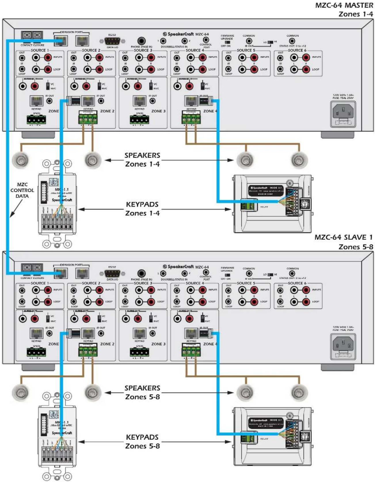
flowchart
graph TD
    subgraph MZC-64 MASTER Zones 1-4
        A["CONTACT CLOSURE"] --> B["SOURCE 1"]
        B --> C["OUT"]
        B --> D["L"]
        B --> E["IR"]
        B --> F["LOOP"]
        G["LOGIP"] --> H["SOURCE 2"]
        H --> I["OUT"]
        H --> J["L"]
        H --> K["IR"]
        H --> L["LOOP"]
        M["VOC"] --> N["KEYPAD SPADS"]
        N --> O["ZONE"]
        P["KEYPAD"] --> Q["KEYPAD SPERS"]
        Q --> R["ZONE 2"]
        S["KEYPAD"] --> T["KEYPAD SPERS"]
        U["ZONE 3"] --> V["SOURCE 3"]
        V --> W["OUT"]
        V --> X["L"]
        V --> Y["IR"]
        V --> Z["LOOP"]
        AA["LOGIP"] --> AB["SOURCE 4"]
        AB --> AC["OUT"]
        AB --> AD["L"]
        AB --> AE["IR"]
        AB --> AF["LOOP"]
        AG["LOGIP"] --> AH["SOURCE 5"]
        AH --> AI["OUT"]
        AH --> AJ["L"]
        AH --> AK["IR"]
        AH --> AL["LOOP"]
        AM["LOGIP"] --> AN["SOURCE 6"]
        AN --> AO["OUT"]
        AN --> AP["L"]
        AN --> AQ["IR"]
        AN --> AR["LOOP"]
    end

    subgraph MZC-64 SLAVE Zones 5-8
        AS["MZC-64 MODE 1"] --> AT["SPEAKERS Zones 1-4"]
        AU["RELLAY"] --> AV["SPEAKERS Zones 1-4"]
        AW["MANUFACTURS"] --> AX["SPEAKERS Zones 1-4"]
        AY["SPEAKERS"] --> AZ["SPEAKERS Zones 1-4"]
    end

    subgraph Other Zones 5-8
        BA["SPEAKERS"] --> BB["SPEAKERS Zones 5-8"]
        BC["SPEAKERS"] --> BD["SPEAKERS Zones 5-8"]
    end

    style MZC-64 MASTER Zones 1-4 fill:#f9f,stroke:#333
    style MZC-64 SLAVE Zones 5-8 fill:#ccf,stroke:#333
Figure 23
MZC-64 Expanded System Speaker, Keypad Connections
SPEAKERS
- Connect the L+,L-/R-R+ Speaker-Level Outputs of each MZC-64 to the appropriate Zone Speakers. (Refer to Figure 23)
EXPANSION
-
Connect one, CAT-5 patch cable terminated with RJ45 connectors (pass-through/pin to pin configuration) from one of the EXPANSION PORT Terminals on the MZC-64 MASTER to one of the EXPANSION PORT Terminals on the next MZC-64 Slave in the chain. (Master to Slave 1, Slave 1 to Slave 2, etc.) NOTE: The Expansion Ports on a given MZC are parallel, so either can be used for expansion connections.
-
Repeat steps 1-2 for all MZC-64s in the chain.
PAGE IN
NOTE: For Phone Paging, 'Y' connectors can be used to connect the paging source line-level audio feed to the PHONE(PAGE IN) jacks on all MZC-64s. As an option, an appropriate audio or audio/video distribution amp can be used to feed the audio paging signal to all MZC's.
-
Connect the line-level audio OUT of the paging source to the line-level audio IN on the distribution amp, using a RCA-RCA patch cable.
-
Connect the audio OUTPUTS of the distribution amp to the PHONE(PAGE IN) Inputs on the MZC-64 Master and Slaves as shown in Figure 24.
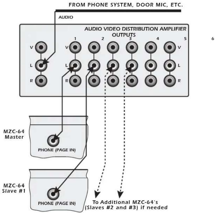
flowchart
graph TD
    A["FROM PHONE SYSTEM, DOOR MIC, ETC."] --> B["AUDIO"]
    B --> C["1 V"]
    B --> D["2 V"]
    B --> E["3 V"]
    B --> F["4 V"]
    B --> G["5 V"]
    C --> H["MZC-64 Master"]
    D --> I["MZC-64 Slave #1"]
    E --> J["MZC-64 Master"]
    F --> K["MZC-64 Slave #1"]
    G --> L["MZC-64 Master"]
    H --> M["PHONE (PAGE IN)"]
    I --> N["PHONE (PAGE IN)"]
    J --> O["PHONE (PAGE IN)"]
    K --> P["PHONE (PAGE IN)"]
    L --> Q["PHONE (PAGE IN)"]
    M --> R["To Additional MZC-64's (Slaves #2 and #3) if needed"]
Figure 24
Page Phone/Video IN Expansion
DOORBELL/STATUS
Loop the Doorbell/Status Trigger Inputs using standard 3.5mm (1/8") Y adaptors to simultaneously trigger the Page Inputs (Doorbell/Status IN) on multiple MZC-64's.
NOTE 1: This application requires standard Y adaptors. DO NOT use the SpeakerCraft SAC-1.0 Y Adapter. The SAC1.0 has 'steering' diodes that will interfere with the signal path in this application.
NOTE 2: These inputs will not function without proper configuration in EZ-Tools.
- Terminate the Trigger Source wire with a 3.5mm mini plug. POLARITY: TIP=+V, SLEEVE=GND.
- Connect Trigger Source to a Y adaptor as shown in Figure 25.
- Daisy-chain the Y adaptors to all MZC-64's in the chain as shown in Figure 25.
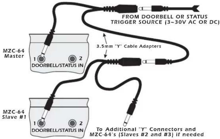
text_image
MZC-64 Master 1 DOORBELL/STATUS IN 2 3.5mm "Y" Cable Adapters MZC-64 Slave #1 1 DOORBELL/STATUS IN 2 FROM DOORBELL OR STATUS TRIGGER SOURCE (3~30V AC OR DC) To Additional "Y" Connectors and MZC-64's (Slaves #2 and #3) if neededFigure 25
Doorbell/Status IN Expansion
COMMON IR OUT
The Common IR Out jacks from multiple MZC-64's can be paralleled and looped using standard 3.5mm ( 18 ) Y adaptors for IR control of a common device (not connected to one of the Source Inputs) from any MZC-64 in the chain.
NOTE: This application requires standard Y adaptors. DO NOT use the SpeakerCraft SAC-1.0 Y Adapter. The SAC-1.0 has 'steering' diodes that will interfere with the signal path in this application.
- Daisy-chain the Y adaptors to the Common IR OUTS on all MZC-64s in the chain as shown in Figure 26.
- Connect an IR emitter to the Y adaptor assembly as shown in Figure 26. Set the LO/HI Common IR Out Switch to LO.
- Attach the IR emitter to the device to be controlled over the IR eye on that device.
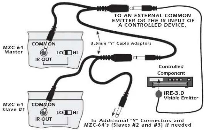
text_image
MZC-64 Master COMMON LO HI IR OUT 3.5mm "Y" Cable Adapters MZC-64 Slave #1 COMMON LO HI IR OUT Controlled Component IRE-3.0 Visible Emitter To AN EXTERNAL COMMON EMITTER OR THE IR INPUT OF A CONTROLLED DEVICE. To Additional "Y" Connectors and MZC-64's (Slaves #2 and #3) if neededFigure 26
Common IR Out Expansion
COMMON STATUS OUT
The Status Out jacks from multiple MZC-64s can be paralleled and looped using standard 3.5mm ( 18 ) Y adaptors for 12 Volt DC control of a common device when any zone in the system is turned on.
NOTE: This application requires standard Y adaptors. DO NOT use the SpeakerCraft SAC-1.0 Y Adapter. The SAC-1.0 has 'steering' diodes that will interfere with the signal path in this application.
- Daisy-chain the Y adaptors to the Common STATUS OUTS on all MZC-64's in the chain as shown in Figure 27.
- Connect a trigger wire to the Y adaptor assembly as shown in Figure 27.
- Terminate the trigger wire as appropriate. Maintain proper polarity. Check connections prior to powering up the system - Improper connection of a voltage trigger can damage system components.
- Connect the trigger wire to the device to be triggered.
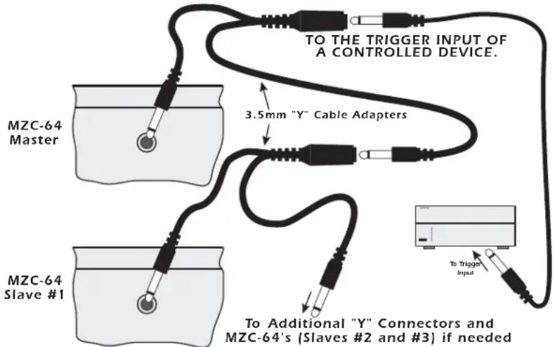
text_image
TO THE TRIGGER INPUT OF A CONTROLLED DEVICE. 3.5mm "Y" Cable Adapters MZC-64 Master MZC-64 Slave #1 To Additional "Y" Connectors and MZC-64's (Slaves #2 and #3) if needed To Trigger InputFigure 27
Common Status Out Expansion
RS485 BUS
In an Expanded System, when connecting MODE Base(s) and MODE Jukebox(es), it will be necessary to add at least one SpeakerCraft RSA-1.0 to create a RS485 bus from one of the MZC Expansion Ports. (Refer to Figure 22) This will provide two-way communication with iPod(s) and Jukebox(es) for Serial Control to the devices and metadata return to the MZC for display on MODE Keypads.
- Connect one end of a CAT-5 Cable, terminated with RJ45 Connectors in a pass-through (pin to pin) configuration to the unused Expansion Port on the MZC-64 Rear Panel.
- Connect the other end of the CAT-5 cable in Step 1 to the RSA-1.0 Expansion Port terminal.
- Connect one end of another CAT-5 patch cable to the RSA-1.0 Expansion Loop terminal.
- Connect the other end of the CAT-5 cable in Step 3 to the Expansion Port on the MODE Adapter as shown in Figure 22.
NOTE: Up to 16 RSA-1.0s can be daisy chained for control of up to 16 RS232 devices. However, only the last RSA-1.0 Loop can be connected to the Expansion Port on a MODE Adapter.
TROUBLESHOOTING
| PROBLEM SOLUTION | |
| Audio | |
| No Audio From External Source a) Confirm source is turned on and playing.b) Check connection between external source and MZC-64. | |
| No Audio In Zone a) Confirm zone is turned on. | b) Confirm volume is turned up and un-mute.c) Confirm speaker connections.d) Confirm zone audio routing command programming.e) In expanded systems, confirm source loop connections between MZC-64's. |
| No Paging Audio a) Confirm paging source is turned on. | b) Confirm paging source connection to "Phone Page In".c) Confirm trigger voltage and polarity to Doorbell/Status In.d) Confirm zone audio paging routing command programming.d) Confirm Doorbell/Status In programming in EZ-Tools. |
| Control | |
| From Keypads a) Confirm MZC-64 has AC power and is turned on.a) Confirm keypad connection to MZC-64.c) Confirm polarity of keypad connections.d) Confirm zone keypad programming in EZ-Tools.e) Confirm connection and placement of IR emitters.f) In expanded systems, confirm, IR loop connections. | |
| Control | |
| From Remote Controls a) Confirm EZ-Code programming (EZ-Codes are zone-specific.) | |
| RS232 a) Confirm power connection to controlled device. | b) Confirm connection to RS232 I/O Port.c) Confirm command properties. |
| Power | |
| System Power a) Confirm connection to an unswitched AC outlet | |
| System | |
| MZC has power, but system does not respond. a) Confirm Firmware Upgrade Switch on Rear Panel is set to OFF for normal operation. | |
MZC-64 Specifications
Audio Sections
Power Output/Channel (RMS, two channels driven into 8 Ohms) 30 Watts, 20Hz to 20kHz
THD (at rated power) <0.7%
Power/Channel (RMS, 2 channels driven into 4 Ohms) 45 Watts @ 1kHz
Input Sensitivity (For rated power @ max VC) 300 μV, VC; 2.8V NVC
Input Impedance (Source Inputs) >22 K Ohms
Input Overload (Source Inputs) 7.2 V
Output Voltage @ Pre-Outs (w/300 V @ Source Inputs) 1.7V, VC Setting, VC Max.
180 μV, NVC Setting
Output Impedance (Pre-Outs) <300 Ohms
Frequency Response (@ 1 Watt @ 8 Ohms) 20 Hz to 20 kHz 12 1.5 dB
Channel Separation > 50 dB @ 10 kHz
Cross Talk Between Sources > 65 dB @ 10 kHz
S/N Ratio (Re: Rated Output, IEC A, Source Inputs Shorted) > 100 dB
Bass Control Range / 10 dB @ 100 Hz
Treble Control Range 1/10 dB @ 10 kHz
Control Sections
| Contact Closures (Dry) | 2A, 30 VAC/DC max |
| Phone Page In - Voltage/Impedance | Audio Line Level, >22k Ohm |
| Doorbell In 1&2, 3V to 30V AC or DC | 10mA @12 VDC/AC |
| Common IR Out - HI (High Power) | 9 V Active High, 82 Ohms |
| - LO (Emitter Power) | 9 V Active High, 670 Ohms |
| Zone IR Outs - Voltage/Impedance | 9.2 V Active High, 620 Ohms |
| Source IR Outs (and Loop) - Voltage/Impedance | 11.5 V Active High, 390 Ohms |
| Common Status Out (0 to 12 V DC) | 9.5 V @ 100 mA |
General
Power Consumption
No signal (idle) 55 Watts
At 18 Rated Power (3.75 Watts/Channel) 125 Watts
Line Ratings (N.A. Version) 120 VAC, 60Hz, 1.8A
Rear Panel Fuse T5AL 250V
Dimensions
17" (432mm) W x *5-¼" (133mm) x 14-¾" (375mm)D
*5-3/4" (146mm) H, including feet
Weight
23lbs (10.5 kg)
LIMITED 2-YEAR WARRANTY
SpeakerCraft Inc. warrants to the original retail purchaser only that this SpeakerCraft product will be free from defects in materials and workmanship for a period of two years, provided the product was purchased from a SpeakerCraft Authorized Dealer.
Defective products must be shipped, together with proof of purchase, prepaid insured to the SpeakerCraft Authorized Dealer from whom they were purchased, or to the SpeakerCraft factory at the address listed on this installation instruction manual. Freight collect shipments will be refused. It is preferable to ship this product in the original shipping container to lessen the chance of transit damage. In any case, the risk or loss or damage in transit is to be borne by the purchaser. If, upon examination at the Factory or SpeakerCraft Authorized Dealer, it is determined that the unit was defective in materials or workmanship at any time during this warranty period, SpeakerCraft or the SpeakerCraft Authorized Dealer will, at its option, repair or replace this product at no additional charge, except as set forth below. If this model is no longer available and cannot be repaired effectively, SpeakerCraft, at its sole option, may replace the unit with a current model of equal or greater value. In some cases where a new model is substituted, a modification to the mounting surface may be required. If mounting surface modification is required, SpeakerCraft assumes no responsibility or liability for such modification. All replaced parts and product become the property of SpeakerCraft Inc. Products replaced or repaired under this Warranty will be returned to the original retail purchaser, within a reasonable time, freight prepaid.
This Warranty does not include service or parts to repair damage caused by accident, disaster, misuse, abuse, negligence, inadequate packing or shipping procedures, commercial use, voltage inputs in excess of the rated maximum of the unit, or service, repair or modification of the product which has not been authorized or approved by SpeakerCraft. This Warranty also excludes normal cosmetic deterioration caused by environmental conditions. This Warranty will be void if the Serial Number on the product has been removed, tampered with or defaced.
This Warranty is in lieu of all other expressed warranties. If the product is defective in materials or workmanship as warranted above, the purchaser's sole remedy shall be repair or replacement as provided above. In no event will SpeakerCraft be liable for any incidental or consequential damages arising out of the use or inability to use the product, even if SpeakerCraft Inc. or a SpeakerCraft Inc. Authorized Dealer has been advised of the possibility of such damages, or for any claim by any other party. Some states do not allow the exclusion or limitation of consequential damages, so the above limitation and exclusion may not apply.
All implied warranties on the product are limited to the duration of this expressed Warranty. Some states do not allow limitation on the length of an implied warranty. If the original retail purchaser resides in such a state, this limitation does not apply.

text_image
Limited 2 YEAR WARRANTYSpeakerCraft offers a variety of accessories to make your installation of this and other SpeakerCraft products easy, economical, and professional. Contact your authorized SpeakerCraft Dealer for more information.
For technical inquires, please call 1-800-448-0976 or e-mail us at techsupport@speakercraft.com. We are available to assist you every weekday, except holidays, between the hours of 7:00 a.m. and 5:00 p.m. PST.