AccuFit IW7 Three - Pregnant SpeakerCraft - Free user manual and instructions
Find the device manual for free AccuFit IW7 Three SpeakerCraft in PDF.


User questions about AccuFit IW7 Three SpeakerCraft
0 question about this device. Answer the ones you know or ask your own.
Ask a new question about this device
Download the instructions for your Pregnant in PDF format for free! Find your manual AccuFit IW7 Three - SpeakerCraft and take your electronic device back in hand. On this page are published all the documents necessary for the use of your device. AccuFit IW7 Three by SpeakerCraft.
USER MANUAL AccuFit IW7 Three SpeakerCraft
natural_image
Exterior view of a white speaker or audio unit with a central circular component and mounting feet (no visible text or symbols)AccuFit IW7 Three | AccuFit IW7 One
INTRODUCTION
Congratulations on purchasing SpeakerCraft's AccuFit IW7 Series of architectural loudspeakers. The AccuFit IW7 Series features sa shallow 2 ^3/4 " sealed steel enclosure. Speakercraft offers the AccuFit Series to address space limitations, building codes, sound transfer to adjoining walls and living environment concerns. The AccuFit IW7 Series of shallow depth, fully enclosed speakers ensure that the drivers have the proper amount of air space to deliver the best performance regardless of the installation environment. This new line of technical advanced speakers was designed to fit just about any installation application.
SPEAKER PLACEMENT
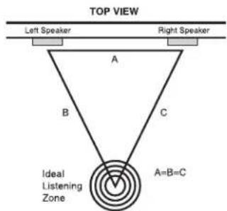
Best results are achieved when the left, right channel speakers are all the same distance away from the listener. The front left and right speakers should be placed so that they form an equilateral triangle, with the listener at one point and each speaker at the other two. (Figure 1) Ideal sound will be achieved when the tweeters are placed at ear level or slightly higher. If the speakers are positioned far away from the primary listening area, adjust the pivoting tweeters so they are pointed toward the primary listening area. NOTE: To avoid possible damage to the pivoting tweeters, read the section entitled "SPEAKER ADJUSTMENTS" in this manual prior to performing the tweeter adjustment.
INSTALLATION CONSIDERATIONS
Before installing your speakers into the wall, you should consider the placement carefully, taking into account the location of electrical, plumbing and other fixtures. Contact your dealer for assistance if you are not sure of the best location in your particular room environment.
MOUNTING SURFACE PREPARATION
New Construction – Unfinished Walls
A New Construction Bracket (available from your dealer), may be installed prior to drywall application across studs (up to 24" on-center) where a speaker will be located. Insulation material should be in place prior to installing drywall. After the hole is cut and the drywall is installed, the speakers are then easily installed following the instructions for mounting in "Finished Walls" below.
Finished Walls
Prior to the actual installation of the speakers, it will be necessary to run cables to the speaker locations. See your dealer for more information about cable installation. After the cable has been properly installed, you are ready to mount the speakers. Following the simple steps listed below will result in a professional looking installation:
- Determine the best area to mount your speakers. This area of the wall should be free of obstructions such as electrical conduit, HVAC ducts, or water lines. This can best be determined by noting the placement of fixtures and gaining access to an attic or crawl space for further analysis of the location of such obstacles.
- Find the studs nearest the desired speaker mounting location. We highly recommend using a good stud-finder tool for this procedure. If you are lining up the speakers to some other object or molding in the room, make sure you consider the size of the baffle flange which extends beyond the mounting hole on all four sides.
- Mark the hole. A template for setting the hole is provided in the box (along with one paint mask insert for use when painting). Position the template in the desired position and pencil an outline on the wall.
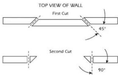
- Cutting the hole. CAUTION: This is the most important part of the entire installation. If you are not certain whether any obstructions exist behind the desired mounting area, you should start by cutting a small hole in the center of your penciled mounting hole with a drywall saw. Cut at a 45^ angle towards the inside of the hole (Figure 2). Cutting the small hole at this angle will make drywall repair much easier as the piece cut out can be installed neatly back into the hole. Once you have determined there aren't any obstructions in your desired mounting location, start cutting the finished hole at a 90^ angle to the wall surface.
text_image
TOP VIEW Left Speaker Right Speaker A B C Ideal Listening Zone A=B=CFigure 1
text_image
TOP VIEW OF WALL First Cut 45° Second Cut 90°Figure 2
text_image
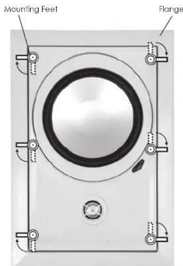
Mounting Feet FlangeFigure 3
SPEAKER INSTALLATION
The unique integral six foot mounting system incorporated into each AccuFit IW7 speaker allows for a quick installation by following these easy steps:
-
Remove the grille. It may be necessary to push one or two of the mounting screws and its attached foot towards the baffle and against the inside surface of the grille to force the grille out of its retaining groove.
-
Attach the speaker cable observing the proper polarity with your amplifier: + (red speaker input) to + and - (black speaker input) to -. Make sure the left channel of the amplifier is connected to the left speaker, and the right channel is connected to the right speaker.
-
Make sure the mounting feet are turned inward to clear the opening, and insert the speaker into the wall. Position the speaker into the hole. NOTE: The flange of the speaker is designed to flex and conform to any small imperfections in the wall's surface. Tighten the six screws on the front of the baffle only enough to make the flange become snug against the wall. As you tighten the screws, the feet will automatically flip into an outward position (Figure 3), thereby clamping the drywall between the feet and the flange.
CAUTION: Over tightening may warp the baffle, crack the ceiling, cause flange to distort, and make the grille difficult to install.
SPEAKER ADJUSTMENTS
Pivoting Tweeter Adjustment
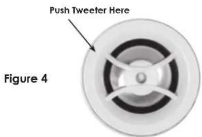
Your AccuFit IW7 Series speakers come from the factory with the tweeter facing straight out from the baffle. This will result in the overall smoothest response. However, depending on your particular primary area, room acoustics, or personal preference, you may find the sound more pleasing by pointing the tweeters in a particular direction. If additional treble is desired in the primary listening area, point the tweeter towards that area; and if less treble is required, point the tweeter away. Push gently at the edge of the tweeter to point it in the desired direction. (Figure 4)
CAUTION: Avoid touching tweeter dome as damage WILL occur on metal dome tweeters (AccuFit IW7 Three).
Adjusting the Frequency Response (AccuFit IW7 Three)
The output of the tweeter on the AccuFit IW7 Three can be adjusted to suit any environment. In general, we recommend leaving all of the adjustments at the flat (0dB) setting. To determine which settings will be appropriate for your speakers, you may need to experiment until the desired sound is achieved. Use the chart to determine the result of the setting you select.
Selecting a Setting on AccuFit IW7 Three
To select a setting, simply use a finger to move the switch mounted on the inner side of the speaker to the desired setting (Figure 5).
Frequency Settings
When selected, the settings will have the following result:
-3dB: Reduces the loudness of the selected frequency
0dB: The selected frequency remains at neutral level
+3dB: Increases the loudness of the selected frequency
PAINTING THE SPEAKERS
If you plan to paint your speakers, we recommend that it be done prior to installation. If you plan to paint your speakers sometime in the future, it is best to remove them by simply reversing the steps for "SPEAKER INSTALLATION". If it is necessary to paint the speakers while they are still in the wall, the paint masks provided in the carton must be installed in place of the grille while the flange is being painted with the ceiling. The grilles can also be painted, however, great care should be taken not to clog the holes, as this will greatly reduce the sound quality of the speakers. SpeakerCraft recommends only light spray painting using 5 parts thinning agent to 1 part paint. Do not paint the grilles while they are attached to the speaker. If it is necessary to paint the under grille material, follow the same procedure used to paint the grilles.
text_image
Push Tweeter Here Figure 4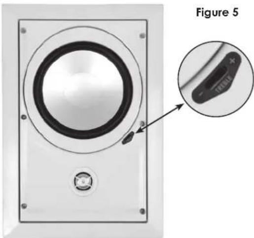
natural_image
Diagram of a speaker with an inset close-up showing the component (no text or symbols present)SPECIFICATIONS
| AccuFit IW7 Three | AccuFit IW7 One | |
| Speaker Type: | 2 Way with a Shallow-Depth, fully sealed Steel Enclosure | 2 Way Shallow-Depth, fully sealed Steel Enclosure |
| Tweeter: | Pivoting 1" Aluminum Dome Tweeter | Pivoting 1" Resin coated Silk Dome Tweeter |
| Woofer: | 7" Aluminum Cone Woofer | 7" Polypropylene Cone Woofer |
| Impedance: | 8 ohms | 8 ohms |
| Sensitivity: | 91dB 1W/1m | 90dB 1W/1m |
| Frequency Adjustments: | Front-Mounted Treble Switch allows the Treble to be set at one of 3 positions: -3dB, Flat, +3dB | None |
| Frequency Response: | 40Hz - 20kHz | 40Hz - 20kHz |
| Power Handling: | 5-125 watts | 5-100 watts |
| Cut Out Dimensions (H x W): | 12 34 " x 8 116 " (323.8mm x 206.3mm) | 12 34 " x 8 116 " (323.8mm x 206.3mm) |
| Dimensions (H x W x D): | 14 12 " x 9 78 " x 2 34 " (368.3mm x 250.8mm x 70mm) | 14 12 " x 9 78 " x 2 34 " (368.3mm x 250.8mm x 70mm) |
In our attempt to constantly improve our products, features and specifications are subject to change without notice.

text_image
Declaration of Conformity CE Mr. Spindler@tcc N.A. Columbia Ave. Boston, CA 10023 USA Solutions conference on intercompanyality of the products described in the company manual use in compliance with technical standards N.A. Columbia Ave. BNC: Brettor N.A. Columbia Ave. Spindler@tcc N.A. Columbia Ave. Boston, CA 10023 8003-445-0761 Fax: (0931) 787-6747 www.spindler@tcc.comLIMITED LIFETIME WARRANTY
SpeakerCraft Inc. warrants to the original retail purchaser only that this SpeakerCraft product will be free from defects in materials and workmanship, provided the speaker was purchased from a SpeakerCraft Authorized Dealer.
Defective products must be shipped, together with proof of purchase, prepaid insured to the SpeakerCraft Authorized Dealer from whom they were purchased, or to the SpeakerCraft factory at the address listed on this installation instruction manual. Freight collect shipments will be refused. It is preferable to ship this product in the original shipping container to lessen the chance of transit damage. In any case, the risk of loss or damage in transit is to be borne by the purchaser. If, upon examination at the Factory or SpeakerCraft Authorized Dealer, it is determined that the unit was defective in materials or workmanship at any time during this warranty period, SpeakerCraft or the SpeakerCraft Authorized Dealer will, at its option, repair or replace this product at no additional charge, except as set forth below. If this model is no longer available and can not be repaired effectively, SpeakerCraft, at its sole option, may replace the unit with a current model of equal or greater value. In some cases where a new model is substituted, a modification to the mounting surface may be required. If mounting surface modification is required, SpeakerCraft assumes no responsibility or liability for such modification. All replaced parts and product become the property of SpeakerCraft Inc. Products replaced or repaired under this Warranty will be returned to the original retail purchaser, within a reasonable time, freight prepaid.
This Warranty does not include service or parts to repair damage caused by accident, disaster, misuse, abuse, negligence, inadequate packing or shipping procedures, commercial use, voltage inputs in excess of the rated maximum of the unit, or service, repair or modification of the product which has not been authorized or approved by SpeakerCraft. This Warranty also excludes normal cosmetic deterioration caused by environmental conditions. This warranty will be void if the Serial Number on the product has been removed, tampered with or defaced.
This Warranty is in lieu of all other expressed warranties. If the product is defective in materials or workmanship as warranted above, the purchaser's sole remedy shall be repair or replacement as provided above. In no event will SpeakerCraft be liable for any incidental or consequential damages arising out of the use or inability to use the product, even if SpeakerCraft Inc. or a SpeakerCraft Inc. Authorized Dealer has been advised of the possibility of such damages, or for any claim by any other party. Some states do not allow the exclusion or limitation of consequential damages, so the above limitation and exclusion may not apply.
All implied warranties on the product are limited to the duration of this expressed Warranty. Some states do not allow limitation on the length of an implied warranty. If the original retail purchaser resides in such a state, this limitation does not apply.

text_image
Limited LIFETIME WARRANTYSpeakerCraft offers a variety of accessories to make your installation of this and other SpeakerCraft products easy, economical, and professional. Contact your authorized SpeakerCraft Dealer for more information. For technical inquires, please call 1-800-448-0976 or e-mail us at techsupport@speakercraft.com. We are available to assist you every weekday, except holidays, between the hours of 7:00 a.m. and 5:00 p.m. PST.

SpeakerCraft®
940 Columbia Ave., Riverside CA 92507 | USA (800) 448 0976 Fax (951) 787 8747 International +1 951 787 0543 | www.speakercraft.com