Polestar II EQ610 - Security Camera EverFocus - Free user manual and instructions
Find the device manual for free Polestar II EQ610 EverFocus in PDF.


User questions about Polestar II EQ610 EverFocus
0 question about this device. Answer the ones you know or ask your own.
Ask a new question about this device
Download the instructions for your Security Camera in PDF format for free! Find your manual Polestar II EQ610 - EverFocus and take your electronic device back in hand. On this page are published all the documents necessary for the use of your device. Polestar II EQ610 by EverFocus.
USER MANUAL Polestar II EQ610 EverFocus
natural_image
Exterior view of two metallic industrial sensors labeled 'Polestar' and 'Solvebox II', shown against a reflective background (no text or symbols on the device body beyond branding)EverFocus®
1/3" Color Day/Night plus Wide Dynamic Range Box Style Camera
Operation Instructions
Model No. EQ610
Please read this manual first for correct installation and operation. This manual should be retained for future reference. The information in this manual was current when published. The manufacturer reserves the right to revise and improve its products. All specifications are therefore subject to change without notice.
PRECAUTIONS
- Do not install the camera near electric or magnetic fields.
Install the camera away from TV/radio transmitters, magnets, electric motors, transformers and audio speakers since the electromagnetic fields generated from these devices may distort the video image.
- Never disassemble the camera beyond the recommendations in this manual nor introduce materials other than those recommended herein.
Improper disassembly or introduction of corrosive materials may result in equipment failure or other damage.
- Try and avoid facing the camera toward the sun.
In some circumstances, direct sunlight may cause permanent damage to the sensor and/or internal circuits.
- Keep the power cord away from water and other liquids and never touch the power cord with wet hands.
Touching a wet power cord with hands or touching the power cord with wet hands may result in electric shock.
- Never install the camera in areas exposed to water, oil or gas.
Water, oil or gas may result in equipment failure, electric shock or, in extreme cases, fire.
- Cleaning
Do not touch the surface of the sensor directly with the hands. Use a damp soft cloth to remove any dirt from the camera body. Use lens tissue or a cotton tipped applicator and ethanol to clean the sensor and the camera lens. Please do not use complex solvents, corrosive or abrasive agents for cleaning.
- Do not operate the camera beyond the specified temperature, humidity or power source ratings.
Use the camera at temperatures within 0°C \~ 50°C (32°F\~122°F) and humidity between 20\~80%. The input power source is 12VDC/24VAC ; 100\~240VAC or 12VDC only.
TABLE OF CONTENTS
- PRODUCT OVERVIEW .... 3
1.1 Main Features .... 3
1.2 Package Contents....3
1.3 Specifications 4 - NAMES AND FUNCTIONS OF PARTS ....5
2.1 Front panel....5
2.2 Top/Bottom Mounting 5
2.3 Back panel and connections ...... 6 - INSTALLATION....9
- RS-485 CONNECTION....10
- CAMERA SETUP OPERATIONS....11
5.1 Setup Buttons....11
5.2 Display/Close the user setup menu screen....12
5.3 LENS....16
5.4 EXPOSURE 16
5.4.1 SHUTTER 16
5.4.2 BRIGHTNESS 16
5.4.3 AGC (Auto Gain Control – basic low light signal amplification) 16
5.4.4 SENSE-UP 17
5.4.5 BLC/BLC 17
5.4.6 BLC/HSBLC 18
5.4.7 D-WDR 18
5.4.8 Return....19
5.5 WHITE BALANCE CONTROL.... 19
5.6 DAY NIGHT....19
5.7 3DNR 20
5.8 SPECIAL 20
5.8.1 CAM TITLE....20
5.8.2 D-EFFECT 21
5.8.3 RS-485 22
5.8.4 MOTION 22
5.8.5 PRIVACY 23
5.8.6 SYNC 23
5.8.7 LANGUAGE 23
5.8.8 RETURN 23
5.9 ADJUST....23
5.9.1 SHARPNESS 23
5.9.2 BLUE 23
5.9.3 RED....23
5.9.4 RETURN 24
5.10 RESET....24
5.10.1 FACTORY RESET 24
5.10.2 RETURN 24
5.11 EXIT 24
6. HOW TO CONTROL AN EQ610 BY A KEYBOARD....24
1. PRODUCT OVERVIEW
Amazing color low light sensitivity of .05 lux before the added benefits of digital signal processing technology, delivered by a 1/3" Sony Super HAD II sensor, is just the beginning with the new EverFocus EQ610. Color without compromise: 560TVL resolution, your choice of full motion color or true day/night images in low light without ghosting, plus Digital Wide Dynamic Range to handle the most
challenging of bright or unbalanced scene lighting conditions. Combined with complete flexibility for selection of lens field of view, electronic or DC iris, wide choices of housing styles and mounting configurations, dual voltage operation and a full suite of OSD Menu and DSP functions controllable at the camera or remotely via RS-485 from a keyboard and/or DVR (3D-DNR to save DVR HDD space, privacy masking, 32X digital zoom, mirroring and rotation, 256X sens-up to a max of .0002 lux, and much more) this is the camera you have been waiting for, and might be the only camera you'll ever need. Two models are available: Day/Night model and True Day/Night with ICR module. EQ610 offers 3 kinds of power sources to satisfy user's different needs.
1.1 Main Features
● Super HAD II sensor at .05 lux has 5X better native light sensitivity before DSP low light boost
● Color without compromise: your choice of full motion color or true day/night images in low light without ghosting
● True Day/Night with ICR module (Optional)
- Starlight super high sensitivity of 0.0002 Lux/F=1.2 is achieved through a sensitivity increase setting of up to 256x
- Digital Wide Dynamic Range expansion to deliver properly exposed images despite bright light sources, deep shadows and/or unbalanced lighting in the same scene
- Provides 3D-Noise Reduction to improve picture clarity while enabling DVRs to improve disk storage utilization
- Accepts C/CS mount manual or DC iris lenses
● Easy to use OSD setup menu with local or RS-485 remote control (DVR or keyboard)
● Motion detection for 4 configurable zones and local alarm output
● Privacy mask function for 8 configurable zones
● Provides digital zoom up to 32x
● Dual voltage (12VDC/24VAC) or Universal power (100\~240VAC) with line lock to AC supply
1.2 Package Contents
- Camera unit
- User's manual
- ND filter
- Accessory pack containing
i. 5mm spacer C/CS Lens adapter
ii. 14 -20 UNC thread mounting bracket and (2) screws
iii. Allen key to for lens back focus set screw
iv. Lens control voltage connector
1.3 Specifications
| Pickup Device 1/3" SONY Super HAD II CCD | |
| Video Format NTSC or PAL | |
| Scanning System | NTSC: 525 TV lines, 60 fields/sec;PAL: 625 TV lines, 50 fields/sec. |
| Picture Elements 768 x 494(NTSC); 752 x 582(PAL) | |
| Horizontal Resolution 560 TVL | |
| Sensitivity 0.05Lux/F=1.2(AGC ON);0.0002Lux/F=1.2 (Sens-up 256x) | |
| S/N Ratio Over 52dB (AGC off) | |
| Electronic Shutter 1/50 (1/60) ~1/100,000 | |
| Video Output | BNC 1.0V p-p 75Ω, |
| Gamma Correction 0.45 | |
| Lens Type | Manual or DC(DD) typeC/CS Mount (lens sold separately) |
| Back Light Compensation Off/BLC/HS BLC Selectable | |
| Auto Gain Control Off/Low/Middle/High Selectable | |
| White Balance ATW/AWB/AWC/Manual/Indoor/Outdoor Selectable | |
| Sync. Mode Internal/Line lock | |
| Day & Night | Auto/Color/BW/EXT (Ext port for switch on command) |
| OSD menu | Multiple functions; local or RS-485 remote control |
| 3D-DNR | Off/On switchable |
| Digital WDR | Outdoor, Indoor |
| Digital Slow Shutter | Sens-Up to 256X |
| Mirror | Off/Mirror/V-Flip/Rotate Selectable |
| Digital Zoom | Off/On selectable up to 32X |
| Motion Detection | Off/On for 4 selectable zones |
| Privacy Mask Off/On for 8 selectable zones | |
| Motion Alarm Output | 1 output (3.3VDC) |
| RS-485 | Control input for menu/configuration |
| Power Source | 12VDC/24VAC ; 100~240VAC; 12VDC only |
| Power Consumption | 12VDC:3W max. ; 24VAC:3W max. ; 100VAC: 4W max. ; 240VAC:5W max. |
| Operating Temperature | 0°C~50°C ; 32°F~122°F |
| Humidity | 20% - 80% non condensing |
| Dimensions | 68mm(W) x 56mm (H) x 120mm (L) ; 2.7"(W) x 2.2"(H) x 4.7"(L) |
| Weight | 0.4 kg / 0.9 lbs |
| Certifications | CE / FCC |
2. NAMES AND FUNCTIONS OF PARTS
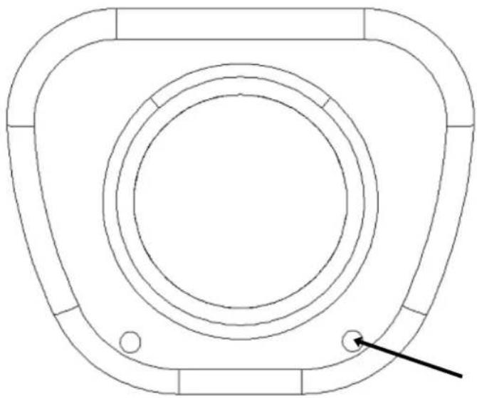
2.1 Front panel
natural_image
Technical line drawing of a circular mechanical component with concentric rings and mounting holes (no text or symbols)Light Sensor
TAKE CARE NOT TO OBSTRCUT THIS OPENING
WITH THE BODY OF THE LENS!
The light sensor is for optional control of D/N switching levels in some applications. See section 5.6 for details.
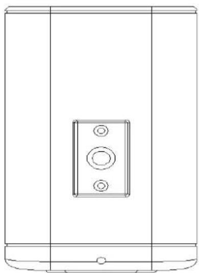
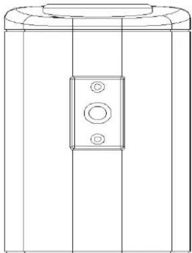
2.2 Top/Bottom Mounting
Using the two phillips head screws provided, the mounting bracket may be mounted to the top of the camera body for suspending the camera; or, the brackets may be mounted to the bottom of the camera body to support the camera.
natural_image
Technical line drawing of a rectangular device with a central button and two circular holes (no text or symbols)Top Bracket
natural_image
Technical line drawing of a cabinet or enclosure with a central square component (no text or symbols)Bottom Bracket
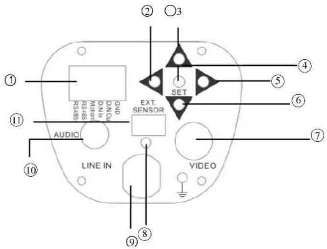
2.3 Back panel and connections
12VDC only
text_image
① ② ③ ④ ⑤ ⑥ ⑦ ⑧ ⑨ AUDIO 12VDC EXT. SENSOR VIDEO100\~240VAC
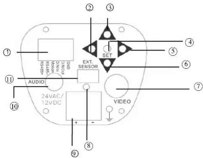
text_image
① ② ③ ④ ⑤ ⑥ ⑦ ⑧ ⑨ R5 485 RS 485 Motion DIN10 DIN10 GND AUDIO LINE IN EXT. SENSOR VIDEO24VAC/12VDC
text_image
① ② ③ ④ ⑤ ⑥ ⑦ ⑧ ⑨ AUDIO 24VAC/ 12VDC EXT. SENSOR VIDEO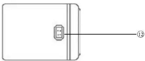
natural_image
Simple line drawing of a rectangular device with a central connector and a numbered label (12) pointing to the right side (no text or symbols on the device itself)① Terminal Block
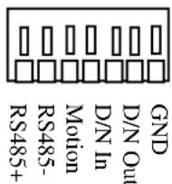
Terminal block connections:
Connect wires to the terminal block by: strip the insulation back 12 " from the end of the wire; press in on the upper tab above the lower wire opening; while holding the tab in, insert the wire; release the tab, pull back gently on the wire to lock it in, and the wire should be retained. Nominal 22-24AWG wire recommended; maximum 18AWG wire may be used.
-GND: Ground pin
-D/N Out: Day/Night control output
If the camera will be used to send out a D/N signal as an external D/N control for any other unit, then the D/N mode of that unit can follow the D/N mode of the camera.
When the camera is at Day mode, it will send out a Low level (0V) signal to any external device. When the camera is at Night mode, it will send out a High level (3.3V) signal any external device.
To use this terminal to control D/N operation, set the D/N selection in the OSD menu to EXT (see Section 5.6), so that the camera will follow an external Day/Night signal instead of the internal AGC level to control any color to B/W switching (examples of possible EXT control devices are: an 'external' light level sensor such as the one mounted in the front face of the camera, an auxiliary light sensor mounted external to the camera, or a control voltage applied to the D/N In terminal). If the "D/N In" terminal is used, it will override the signals from the built-in or auxiliary light level sensors and will command the camera into B/W operation when it is switched to a low voltage level (grounded), or into COLOR operation when it is switched to a 3.3V 'high' level; however, if the D/N In terminal is open/'floating', the AUTO operation switchover from color to B/W will be controlled by the light sensor at the front of the camera body. See Section 5.6 for more information.
-Motion: Alarm output for motion detected.
If the alarm output is connected and a motion is detected, not only will the message "MOTION DETECTED" appear on the screen, but the camera also sends out a high level (3.3V) signal at the motion alarm output. If no motion has been detected, a low level (0V) signal is sent out to the motion alarm output.
-RS485-/RS485+: Connect to RS485 for remote control by keyboard or DVR. RS-485 parameters are set in the OSD menu.
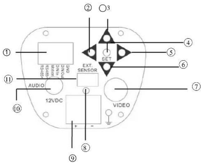
② Menu button for cursor left movement
③ Menu button for cursor up movement
④ Button to access on-screen setting menu and for SET command
⑤ Menu button for cursor right movement
⑥ Menu button for cursor down movement
⑦ Power LED
⑧ Video Output Connector
Connect the video output of the camera to a DVR or other video device through a 75 Ohm type coaxial cable to the BNC female connector at the rear of the camera.
⑨ Power Input Terminal
Connect 12VDC, 24VAC or 100\~240VAC power. For 12VDC model, please connect to the correct polarity.
⑩ Audio Output Connector (for audio model only).
⑪ Ext. Sensor
If a user wants or needs to change the location of the EXT (that is, external and independent of the camera's internal AGC circuit) light level sensor, they can use an External light sensor to connect to this port. (Note: External light sensor kit is an optional product Part # ETHPES-01GR). When this External sensor port is used, and EXT is selected in the DAY/NIGHT menu, the External sensor will be the default light level sensor. The jack accepts a 1/8" diameter miniature phono type plug.
⑫ DC Auto Iris Lens Connector
This connector is used to connect with the DC type auto iris lens using a standard 4 pin male connector

text_image
Pin 1 Pin 2 Pin 3 Pin 4 Direct Drive Cnt- Cnt+ Drv+ Drv- 1 23. INSTALLATION
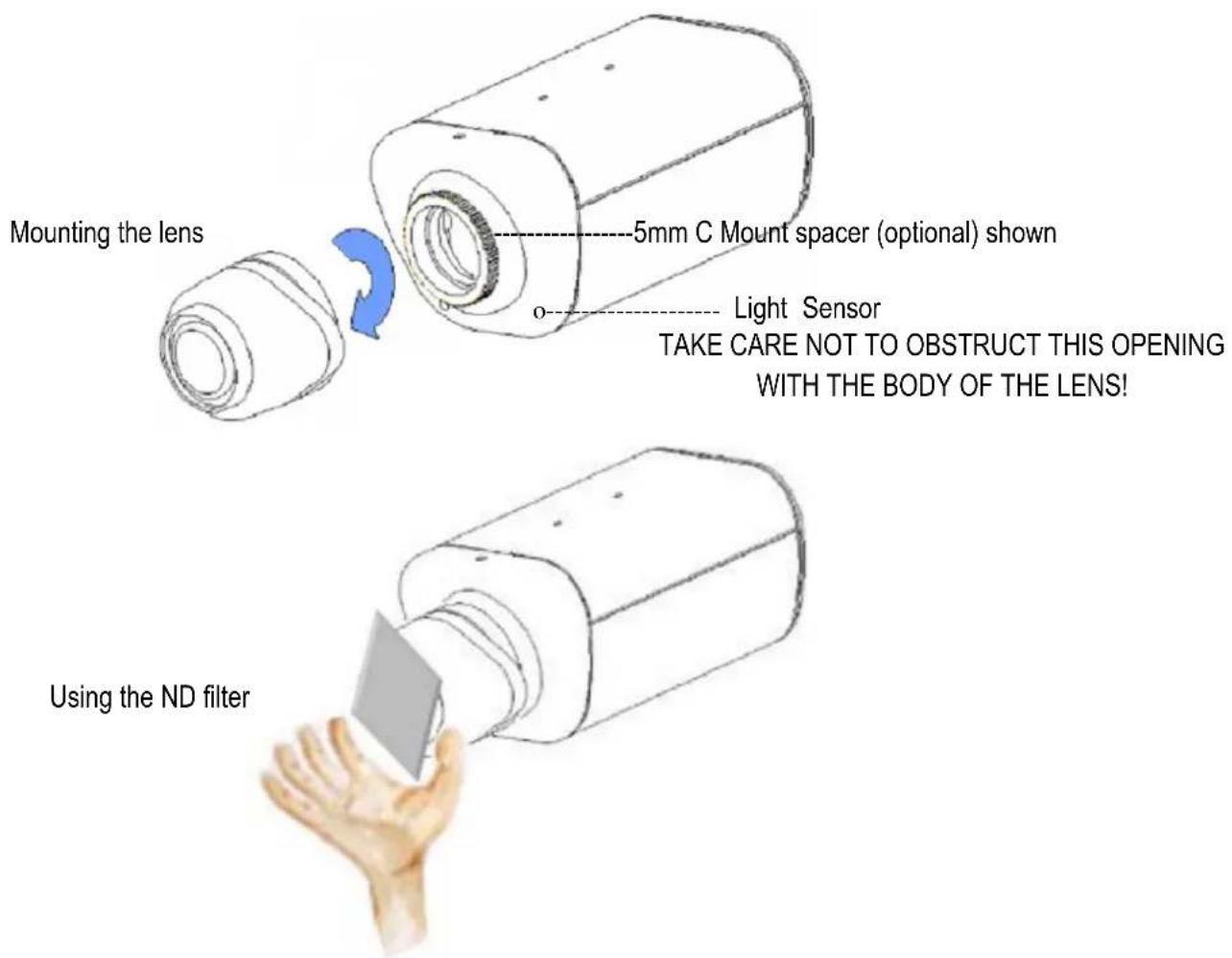
- Unscrew/remove the cover cap from the lens mount.
- If C mount lens is used, please add the C adaptor mount ring (the 5mm thick ring in the accessory pack) between the lens and the mount. Please note: Failure to use a spacer ring when attaching a C mount lens can damage the camera!
- Mount the lens by turning it clockwise into the lens mount.
- If you use an Auto Iris lens, connect the lens cable to the auto iris lens connector on the side of the camera.
- After mounting and connecting the camera, when making final focus adjustments, remove the protective sheets from both sides of the ND filter provided; place the ND filter in front of the lens to force the lens iris to open; then adjust the lens focus until the best image is obtained.
- Lock the lens focus by turning any clamping screws provided on the lens, then remove the ND filter.
text_image
Mounting the lens 5mm C Mount spacer (optional) shown Light Sensor TAKE CARE NOT TO OBSTRUCT THIS OPENING WITH THE BODY OF THE LENS! Using the ND filter4. RS-485 CONNECTION

flowchart
graph TD
    A["RS485 Port#1"] --> B["Audio"]
    B --> C["12VDC"]
    C --> D["Video"]
    D --> E["Computer"]
    style A fill:#f9f,stroke:#333
    style E fill:#bbf,stroke:#333
- Connect the cable from keyboard or DVR RS485 port to the camera's RS485 port.
- Connect the cable from video output BNC of the camera to a monitor or DVR input BNC.
- The RS485 ID set in the OSD Menu on the camera has to be the same as CAM ID used by the keyboard or DVR to control this camera. (Please refer to "5.5.3 RS-485" for RS485 setup detail)
- The baud rate has to be the same for all RS-485 devices on the bus. (Please refer to "5.5.3 RS-485" for RS485 setup details.)
- The EQ610 is programmed using Pelco D type protocol
- Note that the SET/ENTER function to call up the camera menu and to confirm choices is performed by the IRIS + button on the keyboard or DVR.
5. CAMERA SETUP OPERATIONS
This camera utilizes an On Screen Display (OSD) user setup menu.
5.1 Setup Buttons
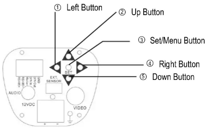
To set items on the user setup menu, use the following buttons on the back panel.
text_image
① Left Button ② Up Button ③ Set/Menu Button ④ Right Button ⑤ Down Button EXT. SENSOR AUDIO 12VDC VIDEO① Left Button: Use this button to select or adjust the parameters of the selected item. The parameter changes each time this button is pressed.
② Up Button: This button is used to move the cursor upwards. Use this button to select the desired item.
③ Set/Menu Button: This button is used to enter the setup menu. If the item has its own submenu (indicated by ←), press this button again to display the sub-menu.
④ Right Button: Use this button to select or adjust the parameters of the selected item. The parameter changes each time this button is pressed.
⑤ Down Button: This button is used to move the cursor downwards. Use this button to select the desired item.
5.2 Display/Close the user setup menu screen
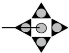
Set button
natural_image
Symmetrical geometric pattern with black and white shapes, no text or symbols presentThe Cursor Buttons & the MENU/SET Button
I. Press the SET button
The menu screen will appear on the monitor.
II. Using the cursor button
Use the cursor buttons ▲ or ▼ to move the cursor up or down. Use the cursor buttons ◀ or ▶ to adjust the mode or parameter settings.
III. Switch to sub-menu screens
When the item with a sub-menu is selected, press the SET button to switch to the sub-menu for further settings.
NOTE:
For those selected items with a “◀” sign at the end, there is a sub-menu for further settings. In many sub-menu screens, the last item choice is either RETURN or END. Selecting this choice and then pressing the LEFT or RIGHT arrow buttons will toggle this choice between RETURN and END. RETURN will exit the current menu to the next higher menu. END will close the current menu and EXIT the menu system. If you have completed all changes, choose END, otherwise choose RETURN to continue setup. Pressing the SET button will activate that choice.
IV. Return to previous page
Press the SET button to return to previous page if the choice displayed is RETURN.
V. Close the menu screen
Press the SET button to exit the menu system if the choice displayed is END (sub-menu) or EXIT (main menu only).
flowchart
graph TD
    A["LENS"] --> B["DC"]
    B --> C["BRIGHTNESS"]
    B --> D["RETURN"]
    B --> E["MANUAL"]
    C --> F["0~100"]
    D --> G["RET, END"]
    E --> H["SHUTTER"]
    H --> I["AUTO(1), x256, x128, x64, x32, x16, x8, x4, x2, 1/60 (or 1/50), FLK, 1/250, 1/500, 1/2000, 1/5000, 1/10000, 1/100000 Only when MANUAL lens selected"]
    E --> J["BRIGHTNESS"]
    J --> K["0~100 DC Lens only"]
    K --> L["AGC"]
    L --> M["OFF, LOW, MIDDLE, HIGH"]
    M --> N["AUTO"]
    N --> O["x2, x4, x8, x16, x32, x64, x128, x256"]
    N --> P["OFF"]
    P --> Q["RETURN"]
    Q --> R["RET, END"]
    E --> S["BLC"]
    S --> T["OFF"]
    T --> U["GAIN"]
    U --> V["MIDDLE"]
    T --> W["BLC"]
    W --> X["DEFAULT"]
    X --> Y["LEFT/RIGHT 0~6"]
    W --> Z["WIDTH 0~6"]
    Z --> AA["TOP/BOTTOM 0~6"]
    W --> AB["HEIGHT 0~6"]
    AB --> AC["RETURN RET, END"]
    S --> AD["HSBLC"]
    AD --> AE["LEVEL 0~8"]
    AD --> AF["DEFAULT"]
    AF --> AG["LEFT/RIGHT 0~6"]
    AD --> AH["WIDTH 0~6"]
    AH --> AI["TOP/BOTTOM 0~6"]
    AD --> AJ["HEIGHT 0~6"]
    AJ --> AK["RETURN RET, END"]
    E --> AL["D-WDR"]
    AL --> AM["OFF, INDOOR, OUTDOOR"]
    AL --> AN["RETURN RET, END"]
flowchart
graph TD
    A["WHITE BAL."] --> B["ATW"]
    A --> C["AWB"]
    A --> D["AWC->SET"]
    A --> E["MANUAL"]
    A --> F["INDOOR"]
    A --> G["OUTDOOR"]
    B --> H["RED"] --> I["0~100"]
    C --> J["BLUE"] --> K["0~100"]
    D --> L["RETURN"] --> M["RET,END"]
    H --> N["BURST"]
    H --> O["RETURN"]
    P["DAY NIGHT"] --> Q["B/W"]
    P --> R["COLOR"]
    P --> S["AUTO"]
    P --> T["EXT"]
    Q --> U["DELAY"] --> V["0~63"]
    Q --> W["S-LEVEL"] --> X["0~100"]
    Q --> Y["E-LEVEL"] --> Z["0~100"]
    Q --> AA["RETURN"] --> AB["0~100"]
    P --> AC["OFF"]
    P --> AD["ON"]
    P --> AE["LEVEL"] --> AF["0~100"]
    P --> AG["RETURN"] --> AH["RET,END"]
    P --> AI["CAM TITLE"] --> AJ["OFF"]
    P --> AK["ON"] --> AL["CAM TITLE"]
    AI --> AM["FREEZE"] --> AN["OFF, ON"]
    AI --> AO["MIRROR"] --> AP["OFF, MIRROR, V-FLIP ROTATE"]
    AI --> AQ["D-ZOOM"] --> AR["ON"] --> AS["D-ZOOM"] --> AT["X1.0~X32"]
    AQ --> AU["PAN"] --> AV["-100~100"]
    AQ --> AW["TILT"] --> AX["-100~100"]
    AQ --> AY["RETURN"] --> AZ["RET,END"]
    AI --> BA["GAMMA"] --> BB["0.05~1.0"]
    AI --> BC["NEG. IMAGE"] --> BD["OFF, ON"]
    AI --> BE["RETURN"] --> BF["RET,END"]
    AI --> BG["CAM ID"] --> BH["0~255"]
    AI --> BI["ID DISPLAY"] --> BJ["OFF, ON"]
    AI --> BK["BAUD RATE"] --> BL["2400,4800,9600,19200,38400,57600"]
    AI --> BM["PROTOCOL"] --> BN["PELCO-D, EVF-1, EVF-2, SETUP MENU"]
    AI --> BO["RETURN"] --> BP["RET,END"]
flowchart
graph TD
    A["MOTION"] --> B["OFF"]
    A --> C["ON"]
    C --> D["AREA SELECT"]
    D --> E["AREA1~AREA4"]
    C --> F["AREA DISPLAY"]
    F --> G["OFF, ON"]
    C --> H["LEFT/RIGHT"]
    H --> I["5~66"]
    C --> J["WIDTH"]
    J --> K["0~93"]
    C --> L["TOP/BOTTOM"]
    L --> M["1~60"]
    C --> N["HEIGHT"]
    N --> O["0~60"]
    C --> P["SENSITIVITY"]
    P --> Q["0~40"]
    C --> R["MOTION VIEW"]
    R --> S["OFF, ON"]
    C --> T["RETURN"]
    T --> U["RET,END"]

    V["PRIVACY"] --> W["OFF"]
    V --> X["ON"]
    X --> Y["AREA SELECT"]
    Y --> Z["AREA1~AREA8"]
    Y --> AA["AREA DISPLAY"]
    AA --> AB["OFF, ON"]
    Y --> AC["LEFT/RIGHT"]
    AC --> AD["6~98"]
    Y --> AE["WIDTH"]
    AE --> AF["0~93"]
    Y --> AG["TOP/BOTTOM"]
    AG --> AH["0~60"]
    Y --> AI["HEIGHT"]
    AI --> AJ["0~61"]
    Y --> AK["COLOR"]
    AK --> AL["0~15"]
    Y --> AM["RETURN"]
    AM --> AN["RET,END"]

    AO["SYNC"] --> AP["INT, L/L"]
    AQ["LANGUAGE"] --> AR["ENGLISH"] --> AS["JAPANESE"] --> AT["TRA.CHINESE"] --> AU["SIM.CHINESE"]
    AV["RETURN"] --> AW["RET,END"]

    AX["ADJUST"] --> AY["SHARPNESS"] --> AZ["0~31"]
    BA["BLUE"] --> BB["0~100"]
    BC["RED"] --> BD["0~100"]
    BE["RETURN"] --> BF["RET,END"]

    BG["RESET"] --> BH["FACTORY RESET"]
    BI["EXIT"] --> BJ["RETURN"] --> BK["RET,END"]
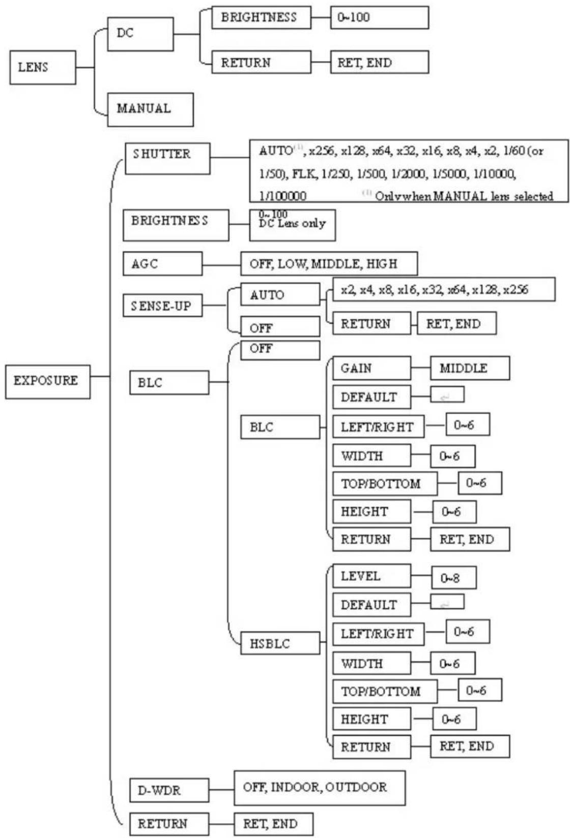
5.3 LENS
- When the SETUP menu is displayed on the screen, please direct the arrow to point to "LENS" by using the UP and DOWN buttons.
- Please select the type of the lens used (Manual/DC type) by pressing the LEFT or RIGHT button.
NOTE:
The brightness of the screen can be adjusted in DC mode in LENS LEVEL. The level can be adjusted from 0 to 100.
- Please select RETURN and press the SETUP button if you would like to return to the previous menu.
5.4 EXPOSURE
5.4.1 SHUTTER
- When the SETUP menu is displayed on the screen, please direct the arrow to point to "EXPOSURE" -> "SHUTTER" by using the DOWN button.
- Select the shutter mode by pressing the LEFT or RIGHT button.
Select from x256, x128, x64, x32, x16, x8, x4, x2, 1/60, Auto, FLK, 1/250, 1/500, 1/2000, 1/5000, 1/10000, 1/00000 for NTSC model or x256, x128, x64, x32, x16, x8, x4, x2, 1/50, Auto, FLK, 1/250, 1/500, 1/2000, 1/5000, 1/10000, 1/00000 for PAL model.
FLK: Please select "FLK" mode when flickering occurs on the screen, because of an irregular balance between illumination and frequency. NTSC model: 1/100, PAL model: 1/120.
AUTO: Shutter speed is automatically controlled depending on the brightness of the screen. This option is available when a manual iris lens is selected above.
- Select RETURN and press the SETUP button when you finish all the settings.
NOTE:
When selecting a DC lens, the shutter speed is fixed as 1/60 for NTSC and 1/50 for PAL.
5.4.2 BRIGHTNESS
Adjust the brightness of the screen (manual lens only). The level can be adjusted from 1 to 100.
5.4.3 AGC (Auto Gain Control – basic low light signal amplification)
- Please direct the arrow to point to "AGC" by using the UP and DOWN buttons.
- Select the level you would like to choose by pressing the LEFT or RIGHT button. The more the level of gain increases, the brighter the screen, but the level of noise increases as well. Please select from HIGH, MIDDLE, LOW and OFF. Note: AGC must be on for sense-up low light boost to function.
5.4.4 SENSE-UP
SENSE-UP is used to keep a brilliant, vivid screen image under low light level conditions by automatically compensating for changes in the level of light.
- Please direct the arrow to point to "SENSE-UP" by using the UP and DOWN buttons.
- Select the mode you would like to operate by pressing the LEFT or RIGHT button.
→ AUTO: Low light level auto mode.
→ OFF: The function is disabled.
NOTE:
① When SHUTTER is in manual mode, SENSE-UP will be disabled.
② When AGC is turned off, SENSE-UP will be disabled.
- Press select RETURN and the SETUP button when you finish all the settings.
NOTES:
① The maximum amplification in low light level situations can be adjusted by pressing the SETUP button in "AUTO" mode. This sets an upper limit on the 'boost'.
② The image becomes brighter when the setting increases; however, the after image increases as well. Due to the increased light sensitivity of the Super Had II chip, far less DSP 'boost' is needed, resulting in color or B/W images in low light with minimal ghosting.
③ Please note that spots and noise may appear if light amplification increases when SENSE-UP is operating. This is a normal phenomenon, controllable with DNR.
5.4.5 BLC/BLC
Video gain can be adjusted automatically to correct the exposure of subjects that are in front of a bright light source.
- Please direct the arrow to point to "BLC" by using the UP and DOWN buttons.
- Select the BLC mode by pressing the LEFT or RIGHT button. Then make adjustments as below:
GAIN: Select from High, Middle and Low.
DEFAULT: Set the factory default values for BLC.
LEFT/RIGHT: Set the Left/Right side of an area for the BLC to be adjusted. The value adjustable is 0\~6.
WIDTH: Set the width of an area for the BLC to be adjusted. The value adjustable is 0\~6.
TOP/BOTTOM: Set the Top/Bottom side of an area for the BLC to be adjusted. The value adjustable is 0\~6.
HEIGHT: Set the height of an area for the BLC to be adjusted. The value adjustable is 0\~6.
RETURN:
Press "RET" to save all settings in the BLC menu and return to the previous menu.
Press "END" to save all the menu settings and exit.
5.4.6 BLC/HSBLC
HSBLC (Highlight Suppression BLC) is used to reduce the brightness of light sources in a specific area. It is activated only in a low illumination environment to minimize the effects of glare from bright lights such as spotlights, street lights or headlights in the field of view. Where ‘traditional’ BLC can increase the exposure of a dark area surrounded by a brighter area, HSBLC can decrease the exposure of bright areas surrounded by darker areas.
- Please direct the arrow to point to "BLC" by using the UP and DOWN buttons.
- Select the HSBLC mode by pressing the LEFT or RIGHT button. Then make adjustments as below:
LEVEL: Adjust the sensitivity level for HSBLC from 0 to 8.
DEFAULT: Set the factory default values for HSBLC.
LEFT/RIGHT: Set the Left/Right side of an area for the HSBLC to be adjusted. The value adjustable is 0\~6.
WIDTH: Set the width of an area for the HSBLC to be adjusted. The value adjustable is 0\~6.
TOP/BOTTOM: Set the Top/Bottom side of an area for the HSBLC to be adjusted. The value adjustable is 0\~6.
HEIGHT: Set the height of an area for the HSBLC to be adjusted. The value adjustable is 0\~6.
RETURN:
Press "RET" to save all settings in the HSBLC menu and return to the previous menu.
Press "END" to save all the menu settings and exit
5.4.7 D-WDR
When there are both bright and dark areas at same time, this function can make both areas properly exposed.
- Please direct the arrow to point to "D-WDR" by using the UP and DOWN buttons.
- Select the mode you would like to operate by moving the joystick LEFT or RIGHT.
OFF: Disables D-WDR function
INDOOR: Select this option if you are in an indoor environment.
OUTDOOR: Select this option if you are in an outdoor environment.
5.4.8 Return
Press "RET" to save all settings in the Exposure menu and return to the previous menu.
Press "END" to save all the menu settings and exit.
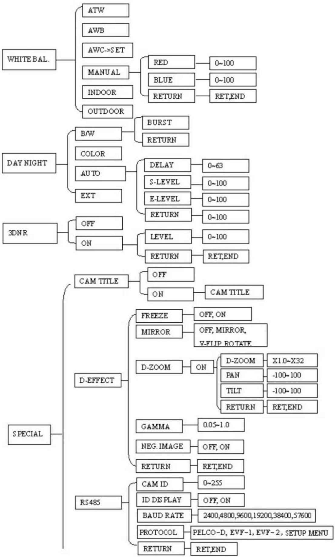
5.5 WHITE BALANCE CONTROL
The screen color can be adjusted by using the WHITE BALANCE function.
-
Please direct the arrow to point to "WHITE BAL" by using the UP and DOWN buttons.
-
Please select the mode you would like to operate by pressing the LEFT or RIGHT button.
Please select one of the 6 modes below:
ATW (Auto Tracking White Balance): This mode can be used within the color temperature range from 5,500^ to 6,000^ (eg, fluorescent light, outdoor, sodium vapor lamp or inside tunnels).
AWB This mode can be used within the color temperature range from 2,500°K to 10,000°K.
AWC->SET: To find the optimal setting for the current luminance environment in this mode, point the camera toward a sheet of white paper, and press "SETUP". If the environment changes, you will have to readjust it.
→ MANUAL: The manual adjustment mode enables a more precise adjustment. Please select ATW or AWC first. Then change to manual adjustment mode and press the SETUP button. Set the suitable color temperature, and increase or decrease the red and blue color values at the same time while checking the color changes of the objects in view.
Press "RET" to save all settings in this menu and return to the previous menu.
Press "ENDsavetail the menu settings and exit
→ INDOOR: Select this option when the color temperature is 5,600°K.
OUTDOOR: Select this option when the color temperature is 3,300^ .
Press "RET" to saves all settings in this menu and returns to the previous menu.
Press "END" to save all the menu settings and exit.
5.6 DAY NIGHT
These settings control the operation of the camera when the illumination level changes. Choices are Color at all times; B/W at all times; or color when illumination is bright, switching to B/W in low light.
⇒ B/W: The picture is always displayed in B/W.
BURST: OFF/ON.
ON: Retains the color burst information; minor color noises may appear when ambient illumination is low.
OFF: With color burst signal off, picture will be pure B/W.
Return: Press "RET" to save all settings in the DAY/NIGHT menu and returns to the previous menu.
Press "END" to save all the setting menus and exit.
COLOR: The picture is always displayed in color, even at low light levels.
AUTO: The picture switches to color in a normal (bright) environment and switches to B/W when the ambient illumination is low. The switching point is determined by the AGC level.
Note: AGC selection must be set as middle or high in order to employ the auto switching function.
Delay: Set the switchover delay time from 0\~63 seconds.
S-Level: Set the start level from 0\~100.
E-Level: Set the end level from 0\~100.
EXT: The picture can switch automatically to color in a normal environment and to B/W when the ambient illumination is low based on the illumination reaching a light sensor; or it may be directly controlled by a trigger voltage. The light sensor at the front of the camera body is the default sensor used to detect illumination. However, if an external light sensor is connected, this external sensor will be used to detect the illumination instead. If the "D/N In" terminal is used, it will override the signals from the built-in or auxiliary light level sensors and will command the camera into B/W operation when it is switched to a low voltage level (grounded), or into COLOR operation when it is switched to a 3.3V 'high' level; however, if the D/N In terminal is open/'floating', the AUTO operation switchover from color to B/W will be controlled by the light sensor at the front of the camera body.
5.7 3DNR
3DNR reduces the background noise in a low luminance environment.
→ OFF: Disables 3DNR to keep the same amount of noise.
⇒ ON: Enables 3DNR to reduce the noise.
Level: adjust noise reduction level from 0\~100.
Press "RET" to saves all settings in DNR menu and returns to the previous menu.
Press "END" to save all the setting menus and exit.
5.8 SPECIAL
In this section, user can do special settings including Cam Title, D-Effect, RS485, Motion, Privacy, Sync, Language and Return.
- Please direct the arrow to point to "SPECIAL" on the SETUP menu by using the UP and DOWN buttons.
- Select the mode you would like to operate by pressing the LEFT or RIGHT button.
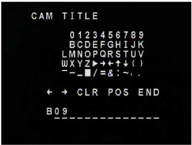
5.8.1 CAM TITLE
Input the camera title, and it will be appeared on the monitor.
1) Please direct the arrow to point to "CAM TITLE" by using the UP or DOWN button.
2) Select "ON" by pressing the LEFT or RIGHT button.
3) Press SETUP button.
4) Maximum 15 letters can be used for the ID.
■ Use UP, DOWN, LEFT and RIGHT buttons to move the cursor to the letter to be chosen.
■ Use SETUP button to choose that letter.
5) Once a name has been selected, please choose a position where you would like to display the name.
■ Move the cursor onto "POS" and press the SETUP button.
■ The name will appear at the top left hand corner.
■ Please use the 4 directional buttons to move the position of the displayed name.
■ Press the SETUP button when the desired location has been reached.
6) If you would like to cancel the ID entered, please move the cursor to "CLR", and all the letters entered will be deleted.
7) Select "END" and press the SETUP button to complete ID input.
text_image
CAM TITLE 0 1 2 3 4 5 6 7 8 9 BCDEFGHIJK LMNOPQRSTUV WXYZ▶→←↑↓( ) --_■/=&:~, . ← → CLR POS END B09 ----5.8.2 D-EFFECT
5.8.2.1 FREEZE (Note that practical application of this feature requires direct access to the camera menu in real time).
-OFF: Select "OFF" to view moving pictures.
-ON: Select "ON" to view still pictures.
5.8.2.2 MIRROR
-OFF: Disable the effects.
-MIRROR: Sets a horizontal image inversion.
-V-FLIP: Set a vertical image inversion.
-ROTATE: Rotate the image 180°.
5.8.2.3 D-ZOOM
Set the digital zoom.
-OFF: Disable the D-ZOOM function.
-ON:
■ D-Zoom: Select digital zoom from X1.0 up to X32. Note that zoom levels above X4 may lead to excessive pixelation.
To control the portion of the magnified image in view (0 is the center of the image):
■ Pan: Select digital pan from -100 to 100.
■ Tilt: Select digital tilt from -100 to 100.
■ Return: Press "RET" to saves all settings in D-ZOOM menu and returns to the previous menu. Press "END" to save all the setting menus and exit.
5.8.2.4 GAMMA
To adjust displayed brightness from 0.05 up to 1.0.
5.8.2.5 NEG. IMAGE
Allows user to create a negative of the original image. A negative image is a tonal inversion of a positive image, in which light areas appear dark and vice versa. A negative color image is
additionally color reversed, with red areas appearing cyan, greens appearing magenta and blues appearing yellow.
5.8.2.6 RETURN
Return: Press "RET" to save all settings in D-EFFECT menu and return to the previous menu. Press "END" to save all the menu settings and exit.
5.8.3 RS-485
-CAM ID: Select RS-485 ID from 1\~255.
-ID DISPLAY: Select "ON" to display RS-485 ID or "OFF" to disable ID display function.
-BAUD RATE: This field is to set the speed at which is used to transmit instruction or information through the RS485 port on the camera. There are six different speeds,
2400,4800,9600,19200,38400 and 57600.
-Protocol: Pelco-D, EVF-1, EVF-2, SETUP MENU.
-Return: Choose "RET" to save all settings in RS485 menu and return to the previous menu. Choose "END" to save all the menu settings and exit.
NOTE:
RS-485 has a higher priority than control at the camera itself. If there is any conflict between local and remote control, the camera will follow the commands from the remote site.
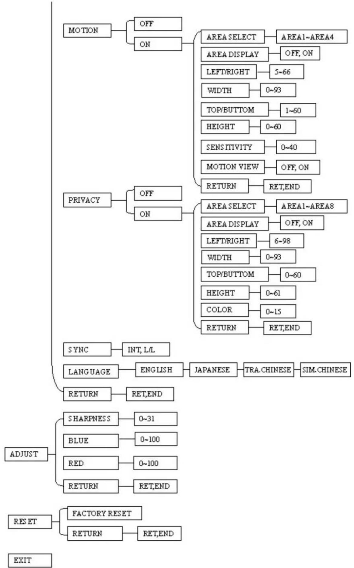
5.8.4 MOTION
This camera enables you to observe movements of objects in 4 different areas on the screen, and the message “MOTION DETECTED” appears on the screen when movement is detected, and a Motion Alarm voltage trigger output is provided at the rear of the camera; this feature may help to improve operational efficiency. The camera detects an object's movement by sensing changes in the pixels displayed.
-OFF: Disables the MOTION function.
-ON:
■ AREA SELECT: Please select the area you would like to detect from the 4 areas in AREA SELECT mode
■ AREA DISPLAY: Select "ON" to use the motion area selected in sensitivity. Select "OFF" to disable this function.
■ LEFT/RIGHT: Set the coordinate of the horizontal axis 5\~66.
■ WIDTH: Set the size of horizontal area 0\~93.
TOP/BOTTOM: Set the coordinate of the vertical axis 1\~60.
■ HEIGHT: Set the size of vertical area 0\~60.
■ SENSITIVITY: Set the sensitivity level for the motion triggered by selecting from 0\~40. When the sensitivity value is high, motion detection sensitivity increases to sense very small movements and vice versa.
■ MOTION VIEW: Select "ON" to display motion detection pixels in the live view.
RETURN: Press "RET" to save all settings in RS485 menu and return to the previous menu. Press "END" to save all the menu settings and exit.
5.8.5 PRIVACY
This mode masks areas you do not want to display on the screen.
-OFF: Disable the PRIVACY function.
-ON:
■ AREA SELECT: Please select the area you would like to hide from the 8 areas in AREA SELECT mode
■ AREA DISPLAY: Select "ON" to use the area selected in the AREA SELECT. Select "OFF" to disable this function.
■ LEFT/RIGHT: Set the coordinate of the horizontal axis 6\~98.
■ WIDTH: Set the size of horizontal area 0\~93.
TOP/BOTTOM: Set the coordinate of the vertical axis 0\~60.
■ HEIGHT: Set the size of vertical area 0\~61.
■ COLOR: Set area color. It is selectable from 0 to 15.
RETURN: Press "RET" to save all settings in RS485 menu and return to the previous menu. Press "END" to save all the menu settings and exit.
5.8.6 SYNC
There are two SYNCHRONIZATION modes: INTERNAL and EXTERNAL LINE-LOCK. In LINE-LOCK mode, the video signal is synchronized to the frequency of the incoming AC power.
The Line-Lock synchronization can only be used when the supply power is 24VAC 60Hz (NTSC models) or 50Hz (PAL models).
-INT: Internal synchronization
-L/L: External line-lock synchronization
5.8.7 LANGUAGE
Select OSD language. EQ610 camera supports multiple languages including English, Japanese, Traditional Chinese and Simplified Chinese.
5.8.8 RETURN
Press "RET" to save all settings in the SPECIAL menu and return to the previous menu. Press "END" to save all the menu settings and exit.
5.9 ADJUST
Adjust sharpness, Blue and Red level in this section.
5.9.1 SHARPNESS
The contour of the video image becomes cleaner and more easily distinguished as the level of SHARPNESS increases. If the level is set too high, it may affect the video image and cause noise. The available range of level is 0\~31.
5.9.2 BLUE
Adjust image's blue level. The available range of level is 0\~100.
5.9.3 RED
Adjust image's red level. The available range of level is 0\~100.
5.9.4 RETURN
Press "RET" to saves all settings in the ADJUST menu and returns to the previous menu.
Press "END" to save all the menu settings and exit.
5.10 RESET
5.10.1 FACTORY RESET
Reset to the default settings.
5.10.2 RETURN
Press "RET" to return to the previous menu.
Press "END" to exit.
5.11 EXIT
Save all the menu settings and exit.
NOTE:
If you quit a Menu without pressing EXIT, all the settings you previously modified will NOT be saved.
6. HOW TO CONTROL AN EQ610 BY A KEYBOARD
- Press IRIS + key to enter the setup menu. If the item has its own setting menu (sign ←), press the IRIS + button again to display the sub-menu.
- Move the joystick ↓ to move the cursor downwards and ↑ to move the cursor upwards. This allows you to move between selection items in setup menu.
- Move the joystick to select or adjust the parameters of the selected item. The parameter changes each time as the item is selected by joystick.
- Move the joystick ← to select or adjust the parameters of the selected item. The parameter changes each time as the item is selected by joystick.
Note:
① When remotely controlled using RS-485, the SET/ENTER button function is equivalent to the bit pattern sent when one presses the IRIS + button. Thus use the IRIS + button on the keyboard or DVR in place of the SET/ENTER button when remotely controlling the EQ610.
② RS-485 has a higher priority than control at the camera itself. If there is any conflict between local and remote control, the camera will follow the commands from the remote site.
EverFocus Electronics Corp.
Headquarters Office
12F, No.79 Sec.1 Shin-Tai Wu Road,
Hsi-Chi, Taipei, Taiwan
Tel: +886-2-26982334
Fax: +886-2-26982380
Beijing office
Room 609, Technology Trade Building.
Shangdi Information Industry Base,
Haidian District, Beijing China
Tel: +86-10-62971096
Fax: +86-10-62971423
European Office
D-46446 Emmerich, Germany
Tel: +49-2822-9394-0
Fax: +49-2822-939495
Japan Office
5F Kinshicho City Building, 2-13-4
Koto-bashi, Sumida-Ku, Tokyo, 130-0022,
Japan
Tel: +81-3-5625-8188
Fax: +81-3-5625-8189
USA California Office
1801 Highland Ave. Unit A
Duarte, CA 91010, U.S.A
Tel: +1-626-844-8888
Fax: +1-626-844-8838
USA New York Office
415 Oser Ave Unit S
Hauppauge, NY 11788
Sales: +1-631-436-5070
Fax: +1-631-436-5027

Your EverFocus product is designed and manufactured with high quality materials and components which can be recycled and reused. This symbol means that electrical and electronic equipment, at their end-of-life, should be disposed of separately from your household waste. Please, dispose of this equipment at your local community waste collection/recycling centre. In the European Union there are separate collection systems for used electrical and electronic product. Please, help us to conserve the environment we live in!