
SR-324 - Security Camera FLIR - Free user manual and instructions
Find the device manual for free SR-324 FLIR in PDF.


User questions about SR-324 FLIR
0 question about this device. Answer the ones you know or ask your own.
Ask a new question about this device
Download the instructions for your Security Camera in PDF format for free! Find your manual SR-324 - FLIR and take your electronic device back in hand. On this page are published all the documents necessary for the use of your device. SR-324 by FLIR.
USER MANUAL SR-324 FLIR
Installation and Operation Manual
natural_image
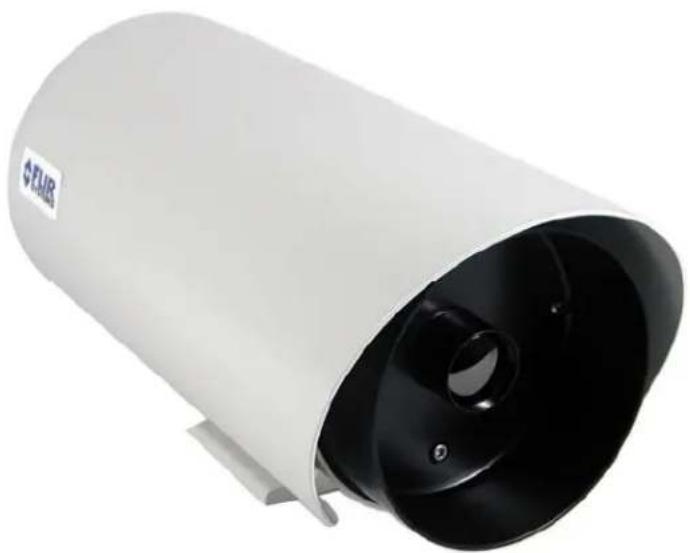
White cylindrical device with black ventilation grille, labeled 'FLMR' on the side (no other text or symbols visible)FLIR Systems, Inc.
70 Castilian Drive
Goleta, CA 93117
Phone: 888.747.FLIR (888.747.3547)
International: +1.805.964.9797
http://www.flir.com
Camera Models
SR-124 SR-117 SR-112
SR-348 SR-334 SR-324
SR-313 SR-309 SR-304
SR-645 SR-625 SR-618
SR-612 SR-606
FLIR Systems Inc.
70 Castilian Dr.
Goleta, CA 93117-3027
888.747.FLIR (888.747.3547)
| Revision | Date Notes | |
| 100 | 03/27/2010 | Initial release |
| 110 04/22/2010 Minor modifications to cover and headers | ||
| 120 07/30/2010 Added other camera models (SR-1XX and SR-3XX) | ||
| 130 04/06/2011 Added F CC Regulatory Information, added SR-6xx cameras | ||
EXPORT RESTRICTIONS
This document is controlled to FLIR Technology Level 1. The information contained in this document pertains to a dual use product controlled for export by the Export Administration Regulations (EAR). FLIR trade secrets contained herein are subject to disclosure restrictions as a matter of law. Diversion contrary to US law is prohibited. US Department of Commerce authorization is not required prior to export or transfer to foreign persons or parties unless otherwise prohibited.
PROPRIETARY
The data in this publication shall not be disclosed without permission and shall not be duplicated, used, or disclosed in whole or in part except to the extent provided in any contract of which this document is made a part. This restriction does not limit the customer's right to use information contained in this document if it is obtainable from another source without restriction. The data subject to this restriction are contained in all sheets of this document and related drawings and document specifications herein. FLIR reserves the right to make changes to its products or specifications at any time, without notice, in order to improve design or performance and to supply the best possible product.
COPYRIGHT
Copyright © FLIR Systems, Inc. All rights reserved. This publication, or any parts thereof, may not be reproduced in any form without the express written permission of FLIR Systems, Inc.
FEDERAL COMMUNICATIONS COMMISSION REGULATORY INFORMATION
Modification of this device without the express authorization of FLIR Commercial Systems, Inc., may void the user's authority under the FCC Rules to operate this device.
Note: This equipment has been tested and found to comply with the limits for a Class A digital device, pursuant to part 15 of the FCC Rules. These limits are designed to provide reasonable protection against harmful interference when the equipment is operated in a commercial environment. This equipment generates, uses, and can radiate radio frequency energy and, if not installed and used in accordance with the instruction manual, may cause harmful interference to radio communications. Operation of this equipment in a residential area is likely to cause harmful interference in which case the user will be required to correct the interference at his own expense.
Shielded cables must be used to connect this device to other devices.
Pelco is a registered trademark of Pelco. Windows is a registered trademark of Microsoft Corporation.
TABLE OF CONTENTS
1 WARNINGS AND CAUTIONS 5
2 INTRODUCTION....6
2.1 Serial Remote Control 6
2.2 SR-Series Camera Models 7
2.3 Camera Enclosures 8
2.4 Package Contents 8
3 INSTALLATION OVERVIEW 9
3.1 Accessing the Electrical Connections....9
3.2 Ground Connection 9
3.3 Input Power 10
3.4 Serial Communications.... 11
3.5 Sealed Cable Glands....12
3.6 Analog Video Output 13
3.7 Camera Mounting....13
4 INSTALLATION 14
4.1 Open Camera Enclosure 14
4.2 DIP Switch Settings 15
4.3 Camera Installation....16
5 OPERATING THE SR-SERIES THERMAL CAMERA.... 19
5.1 Advantages of Thermal Imaging.... 19
5.2 Thermal Imaging....19
5.3 Configuration and Control....20
5.4 Flat Field Correction (FFC)....20
6 CARING FOR YOUR SR-SERIES THERMAL CAMERA 21
6.1 Temperature....21
6.2 Maintenance....21
7 TROUBLESHOOTING PROBLEMS....22
8 SR-SERIES CAMERA SPECIFICATIONS.... 24
8.1 SR-Series Camera Dimensions....26
9 REFERENCES....27
TABLE OF FIGURES
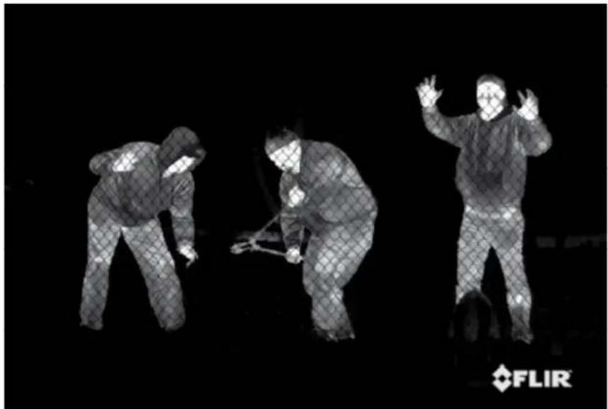
Figure 1-1: Thermal image from SR-Series camera ....4
Figure 2-1 : Daylight camera on left; Thermal image on right....6
Figure 2-2: White Hot palette on left, Black Hot palette on right....7
Figure 2-3: SR-35 Camera with and without the Environmental Enclosure....8
Figure 3-1: Rear view of SR-Series camera....9
Figure 3-2: Earth Ground Connection....10
Figure 3-3: Serial Communications Options .... 11
Figure 4-1: Front view of SR-Series camera....14
Figure 4-2: Serial Communications DIP Switches ....15
Figure 4-3: SR-Series Connections ....17
Figure 4-4: Tongue and Groove Alignment....18
Figure 5-1: Backlit daylight camera on left; thermal image on right....19
Figure 8-1: Camera Side View....26
Figure 8-2: Camera Rear View ....26
Figure 8-3: Enclosure Mounting Foot....27
natural_image
Three individuals in protective gear performing a physical maneuver against a dark background, with FLIR logo visible in corner (no text or symbols on figures)Figure 1-1: Thermal image from SR-Series camera
1 WARNINGS AND CAUTIONS
Warning! This guide uses the term Warning! to indicate a potentially hazardous situation, which, if not avoided, may result in bodily harm or injury, damage to the camera, or other property damage.
Protect Your Investment
The camera should be installed by a trained professional according to local codes and industry-standard safe practices.
Proper ESD protocol should be followed while working inside the unit.
The camera is a precision optical instrument and should not be exposed to excessive shock or vibration.
Avoid pointing the system directly at extremely high-intensity radiation sources, such as the sun, lasers, arc welders, etc. This warning applies whether or not the system is powered.
Great care should be used with your camera's optics. They are delicate and can be damaged by improper cleaning. Only clean the lens in the manner described in section 6 Caring for your SR-Series Thermal Camera.
Legal Considerations
Camera and audio surveillance may be prohibited by laws that vary from country to country. Check the laws in your local region before using this product for surveillance purposes.
Support
If you have questions that are not covered in this manual, or need more information, contact your local FLIR service representative or, 1 (877) 773-3547 inside the US.
In the US, you can reach FLIR Customer Support at (888) 747-FLIR (747-3547).
Important! All thermal imaging systems are subject to export control. Export outside of the US is controlled by the US Government. Please refer to your FLIR regional sales office or authorized FLIR distributor/reseller for transfers outside of the US and for export compliance information concerning your application or geographic area.
This equipment must be disposed of as electronic waste. Contact your nearest FLIR representative for instructions on how to return the product to FLIR for proper disposal.
2 INTRODUCTION
The SR-Series Thermal Camera you have purchased is a sophisticated thermal imaging camera that provides excellent night visibility and situational awareness, even in absolute darkness. The camera has a standard video output that works with digital video recording devices, video motion detection software or off-the-shelf video encoders.
FLIR's powerful SR-Series thermal security cameras compliment and complete your security camera network. They turn night into day, allowing you to see intruders invisible to the naked eye. SR-Series cameras create video images from infrared thermal energy (heat), and perform well at night and day, in good weather and bad. The SR Series thermal surveillance camera system is intended for various commercial and industrial applications, including security and surveillance.
natural_image
Foggy urban scene with buildings and trees in the foreground (no visible text or symbols)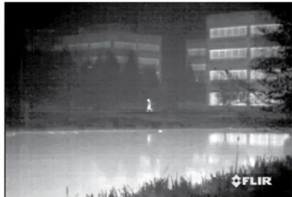
natural_image
Exterior view of a modern office building with glass facade and visible reflection in foreground (no signage)Figure 2-1 : Daylight camera on left; Thermal image on right
Observe that the image on the left from an ordinary daylight camera is obscured by fog; the thermal image on the right provides clear details.
The SR-Series camera is designed for simple, intuitive installation and operation. Each model is based on the widely-deployed uncooled microbolometer imaging core from FLIR known as Tau. All cameras include FLIR's advanced image processing techniques which deliver excellent contrast regardless of scene dynamics. Unlike other night vision systems that require low amounts of light to generate an image, the SR-Series thermal imagers need no light at all.
2.1 Serial Remote Control
The SR-Series cameras support serial communication for control of camera features. The serial standard is user-configurable to the RS-232 or RS-422 signaling standard via a DIP switch inside the camera. Each camera is pre-configured at the factory to support RS-232.
The camera ships with a CD-ROM that includes the SR-Series control software known as the FLIR Camera Controller GUI ^1 . Users can control the camera through the Windows®-based graphical user interface, which allows the user to operate the following functions or features:
• Digital zoom (2X, 4X)
- Selectable Automatic Gain Control (AGC) and Dynamic Detail Enhancement (DDE) settings for optimization of video imagery
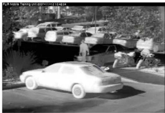
- Camera Palette (also known as Polarity) - by default the White Hot palette is used; alternatively the Black Hot palette displays warmer objects as black or dark rather than white or light shades. Additional pseudo color palettes are available using the application software supplied with the camera.
Refer to the Tau Camera User's Manual (TAU-0035-00-10) for more information about specific camera settings. The software and the manual are available on the CD shipped with the camera or from the FLIR web site: http://www.flir.com/cvs/cores/resources/.
natural_image
Black-and-white photo of a parked car on a paved road with vehicles and trees in the background (no visible text or symbols)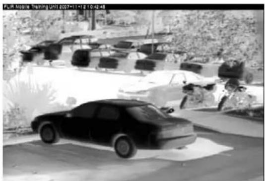
natural_image
Black-and-white photo of a car parked in an outdoor parking lot with parked cars and vegetation (no visible text or symbols)Figure 2-2: White Hot palette on left, Black Hot palette on right
2.2 SR-Series Camera Models
The cameras are available with a choice of lenses for short-, medium- and long-range surveillance capability. All SR-series cameras can be used on a fixed-mount or pan/tilt platform and provide crisp, clear thermal imagery in total darkness, light fog or smoke.
| Camera Model | Field of View (HxV) | Resolution | Focal Length |
| SR-124 24° x | 20° 160x120 9 mm | ||
| SR-117 17° x | 14° 160x120 13 mm | ||
| SR-112 12° x | 10° 160x120 19 mm | ||
| SR-348 48° x | 39° 320x240 9 mm | ||
| SR-334 34° x | 28° 320x240 13 mm | ||
| SR-324 24° x | 19° 320x240 19 mm | ||
| SR-313 13° x | 10° 320x240 35 mm | ||
| SR-309 9° x 7° | 320x240 50 mm | ||
| SR-304 4.6° x | 3.7° 320x240 100 mm | ||
| SR-645 45° x | 37° 640x480 13 mm | ||
| SR-625 25° x | 20° 640x480 25 mm | ||
| SR-618 18° x | 14° 640x480 35 mm | ||
| SR-612 12° x | 10° 640x480 50 mm | ||
| SR-606 6° x 5° | 640x480 100 mm |
2.3 Camera Enclosures
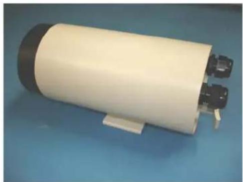
SR-Series cameras are packaged in environmental enclosures that meet IP66 test standards. Refer to section 8 SR-Series Camera Specifications for additional information. The camera's sun shroud around the enclosure helps regulate the camera temperature in direct-sun installations. Each camera uses an athermalized lens and a lens heater to provide sharp imagery in all temperature and weather conditions, ensuring a clear lens and high-quality infrared video, even in extremely cold environments.
natural_image
Exterior view of a cylindrical electronic device with two ports and a black cover, placed on a blue surface (no text or symbols visible)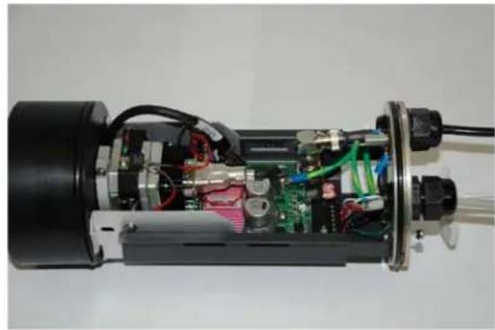
natural_image
Interior view of an electric motor with exposed circuit board and wiring (no text or symbols visible)Figure 2-3: SR-309 Camera with and without the Environmental Enclosure
2.4 Package Contents
Refer to the Shipping Check List that is shipped with each camera for a description of the parts and components that are included with the camera. If there is any discrepancy between the list and the contents of your shipment, please contact FLIR Systems Customer Support immediately using the contact information at the front of this manual.
3 INSTALLATION OVERVIEW
General installation information for all SR-series cameras is given below.
If you have a question regarding installation or operation of your SR-Series camera, contact FLIR Systems, Inc Customer Support, using the contact information at the front of this manual. Check out our training web site (http://www.flir.com/training/) to get information on courses offered and to learn how you can become a FLIR-authorized Installer.
Take care during installation to avoid scratching the camera lens. Do not expose the camera to direct sun for long periods without the sun shroud installed.
3.1 Accessing the Electrical Connections
text_image
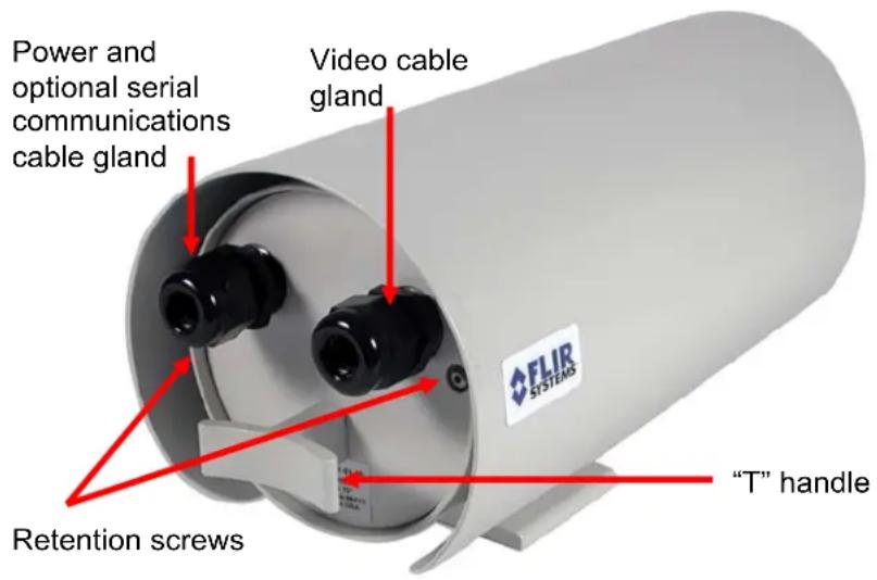
Power and optional serial communications cable gland Video cable gland FLIR SYSTEMS "T" handle Retention screwsFigure 3-1: Rear view of SR-Series camera
It is necessary to remove the rear of the enclosure in order to access the electrical connections. The SR-Series provides electrical contacts in the form of screw-terminal jacks, allowing it to receive 16-24 AWG tinned leads from the power supply and serial communication interface.
3.2 Ground Connection
The SR-Series cameras have grounding and surge protection to provide further immunity from high current transients that can occur in installations that are subject to electrical storms and/or nearby lightning events. In order to ensure CE and FCC compliance as well as to protect against these high current events, installers are required to provide an Earth connection to a specific connection on the camera. Note: a ground connection to the exterior of the camera (for example, to the mounting foot) is insufficient.
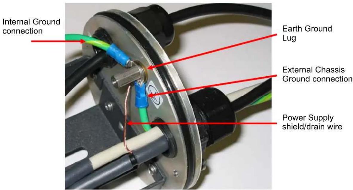
When the camera is shipped from FLIR, an internal ground wire (green) connects the interface board to the Earth Ground Lug, located on the inside of the rear of the enclosure. If is it disconnected during the installation, it must be reconnected. For proper installation, a ground connection from an external Earth ground must be connected to the Earth Ground Lug as shown in Figure 3-2: Earth Ground Connection. Typically the Earth ground connection will be part of the power cable bundle.
text_image
Internal Ground connection Earth Ground Lug External Chassis Ground connection Power Supply shield/drain wireFigure 3-2: Earth Ground Connection
Warning! The camera must be installed according to industry-standard practices and local electrical codes. Failure to properly connect the enclosure and the electrical interface board to ground could result in damage to the camera and possible bodily injury.
3.3 Input Power
The SR-Series cameras operate on either 24VDC or 24VAC power (nominal). Refer to the section titled SR-Series Camera Specifications for additional power requirements. The cameras provide screw-terminals for receiving tinned leads for input power.
The power cable should be twisted pair or triple, with an overall shield or conduit connected to the enclosure rear panel ground lug, as described in the previous section.
The system is fuse-protected against over-voltage conditions. A blown fuse is an indication either that the circuit has been overloaded or that a short circuit has occurred somewhere in the circuit. A wiring problem may be placing too much of a load on the circuit if a fuse blows after plugging in or turning on the camera. Before replacing the fuse it is important to identify what has caused it to fail.
Prior to changing a fuse, turn off the electrical circuit or completely disconnect the camera. Make certain that no dangerous condition exists before restoring power. Replace the fuse with a fuse that is of the same rating and proper for the circuit. Never use anything other than a fuse of proper rating.
Warning! Failure to disconnect power to the camera while replacing a fuse could result in accidental injury or death or could damage the camera.
3.4 Serial Communications
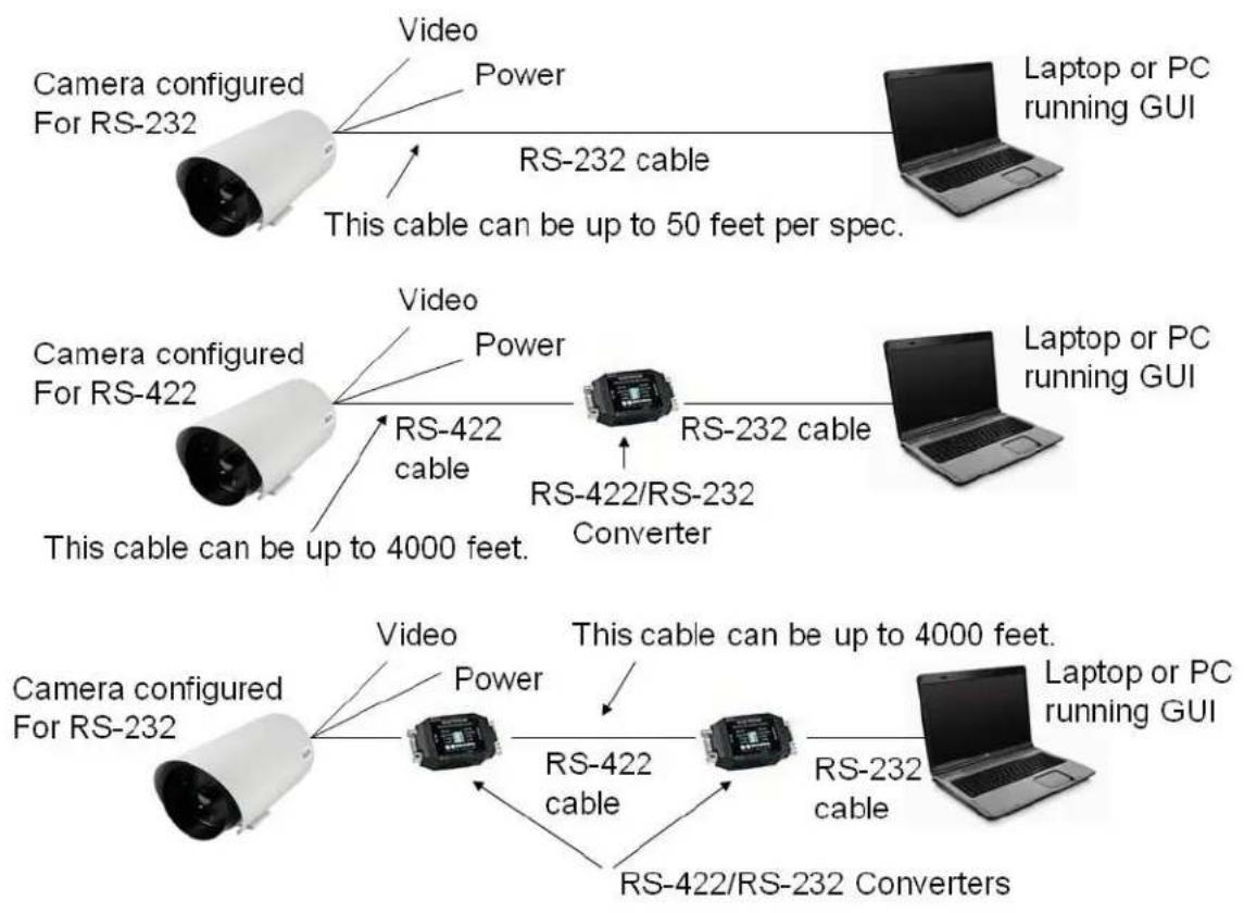
For serial communications, there are several choices available to the installer and the camera user. If the camera is configured for RS-232 protocol, then it may be directly attached to a PC or laptop running the FLIR Camera Controller graphical user interface (GUI) software, which is included with the camera or downloaded from the FLIR website.
If the camera is configured for RS-422, then a communication protocol converter (also known as a serial 232-422 converter) can be used to connect to a laptop or PC running the appropriate GUI software, allowing a longer cable run.
The following diagram illustrates these communication options.
flowchart
graph TD
    A["Camera configured For RS-232"] -->|Video Power| B["Laptop or PC running GUI"]
    A -->|RS-232 cable| C["This cable can be up to 50 feet per spec."]
    D["Camera configured For RS-422"] -->|Video Power| E["RS-422 Cable"]
    D --> F["RS-422/RS-232 Converter"]
    F --> G["Laptop or PC running GUI"]
    H["Camera configured For RS-232"] -->|Video Power| I["RS-422 Cable"]
    H --> J["RS-422/RS-232 Converters"]
    I --> K["This cable can be up to 4000 feet."]
    J --> L["RS-232 Cable"]
    L --> M["Laptop or PC running GUI"]
Figure 3-3: Serial Communications Options
The serial cable should be 100 ohm impedance twisted pair with an overall shield. For RS-232, the cable length should be no longer than 50 feet; for RS-422 the cable should be no longer than 4000 feet. Many laptops may not have a standard 9-pin serial port, and therefore a device such as a USB-serial adaptor may be needed.
3.5 Sealed Cable Glands
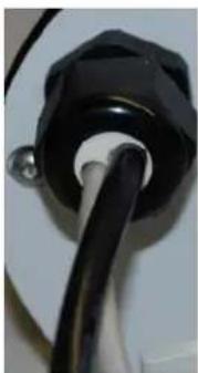
Cables enter the SR-Series cameras through liquid-tight compression glands. Be sure to insert the cables through the cable glands on the rear of the enclosure before terminating and connecting to the camera (the terminated BNC video cable will not fit through the cable gland). The camera power cable (and serial cable, if used) should be inserted through the cable gland on the left of the rear of the enclosure, and the video cable should be inserted through the cable gland on the right. Leave the glands loosened until the cable installation has been completed.
natural_image
Close-up of a black electrical plug with a wire inserted (no visible text or symbols)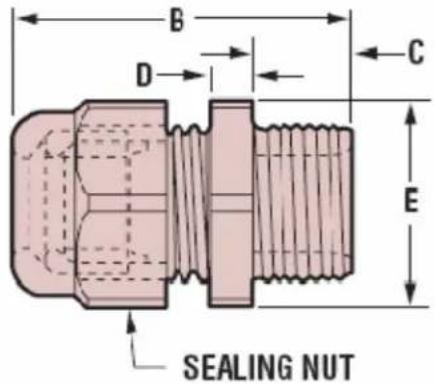
text_image
B D C E SEALING NUT| PART DIMENSIONS | |||||||||
| AClearanceHole | BMax. O.A.Length | CThreadLength | DWrenchingNut Thk. | EWrenchingFlats | |||||
| in | mm | in | mm | in | mm | in | mm | in | mm |
| .875 | 22,2 | 1.72 | 43,7 | .62 | 15,7 | .20 | 5,1 | .95 | 24,1 |
Inspect and install gland fittings with suitable leak sealant and tighten to ensure water tight connection. The gland generally will not tighten flush against the back plate. Water intrusion at the gland seals due to improper installation will void the warranty. An example of a suitable leak sealant is DuPont RectorSeal ^® T plus 2 ^® non-hardening paste-type pipe sealant with Teflon.
In order to maintain a proper seal, each cable gland should contain a single cable sheath. Installing more than one cable bundle in the cable seal may compromise the seal. If separate cables are to be used for power and serial communications, the gland should be changed to a Heyco®-type multi-hole NPT hub, with the hole size dependent on the cable outside diameter (http://www.heyco.com/).
FLIR Systems, Inc. recommends a minimum cable diameter of 1/4" through the cable glands in order to maintain adequate environmental sealing.
3.6 Analog Video Output
The analog video signal is accessed via a standard coaxial cable BNC connector and meets the requirements of NTSC or PAL video standards, depending on the configuration ordered. The analog video signal is intended to drive video coaxial cable (RG-59 or equivalent) and is designed to transmit a 75 ohm load with minimum signal loss. Excessive signal loss and reflection occurs if cable rated for other than 75 ohms is used. Cable characteristics are determined by a number of factors (core material, dielectric material and shield construction, among others) and must be carefully matched to the specific application. Moreover, the transmission characteristics of the cable will be influenced by the physical environment through which the cable is run and the method of installation.
In video security systems, camera signals must travel from the camera to the monitor. Proper termination of cables is essential to a system's reliable performance. The end point of any video cable run must be terminated in 75 ohms. Usually, the cable run will end at the monitor, which will ensure that this requirement is met.
3.7 Camera Mounting
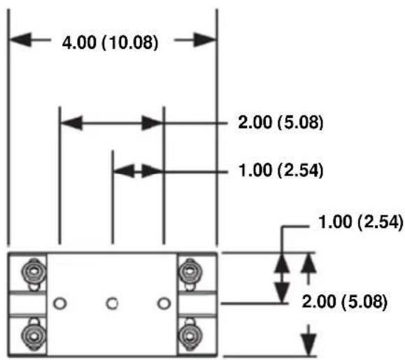
Mounting the SR-Series camera is accomplished using the 14 x20 tripod mount holes on the underside of the enclosure foot. FLIR Systems recommends using the supplied hardware. The dimensions of the camera mounting foot are provided in the section titled SR-Series Camera Specifications for reference.
The enclosure can be mounted via the enclosure foot to a wall mount, ceiling or pedestal mount, or a pan/tilt mechanism on a wall or ceiling. The enclosure should be attached by a minimum of two 14 x20 fasteners. For further mounting instructions, see the documentation accompanying the fixed or pan/tilt mount. The screws that attach the camera enclosure to its foot are 3/32" head hex screws. The screws that attach the sun shield to the foot are 9/64" hex head screws.
4 INSTALLATION
Prior to installing the SR-Series camera, be sure to review the general installation procedures given above. Each camera system has a fixed-focus lens and it is not necessary to adjust the focus when the camera is installed.
Be sure to insert the cables through the cable glands on the rear of the enclosure before terminating and connecting to the camera (the terminated cable will not fit through the cable gland).
Be sure to properly ground the camera according to the information provided in section 3.2 Ground Connection.
Caution! Proper ESD protocol should be followed at all times while working inside the unit.
4.1 Open Camera Enclosure
It is necessary to remove the rear of the enclosure in order to access the electrical connections. It may also be necessary to remove the front of the enclosure and remove the camera from the enclosure in order to access the DIP switches. Note: The SR-Series cameras come pre-configured for RS-232 communication from the factory and the installer may change the option via a DIP switch. The switch would only need to be accessed if changing from the default RS-232 to RS-422.
Remove the camera from the enclosure as follows:
- Loosen the two captive hex screws from the rear of the camera enclosure using a 1/8" hex wrench as shown in Figure 3-1.
- Pull the back of the environmental enclosure off using the "T" handle.
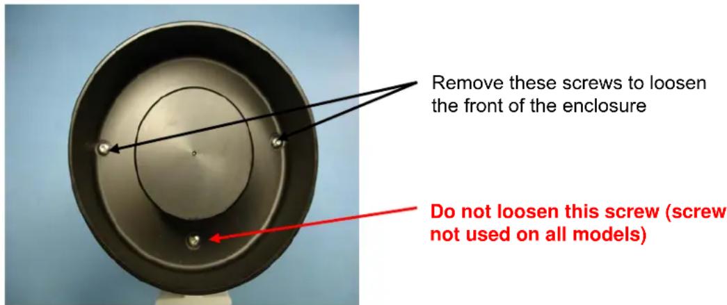
- If necessary, remove the two Phillips screws on the front of the enclosure as indicated in the figure below.
text_image
Remove these screws to loosen the front of the enclosure Do not loosen this screw (screw not used on all models)Figure 4-1: Front view of SR-Series camera
- Push the camera assembly out of the front of the enclosure from the back using the lower left and right parts of the chassis as push points. The ground cable inside the enclosure may have to be temporarily disconnected from the rear plate before removing the camera.
4.2 DIP Switch Settings
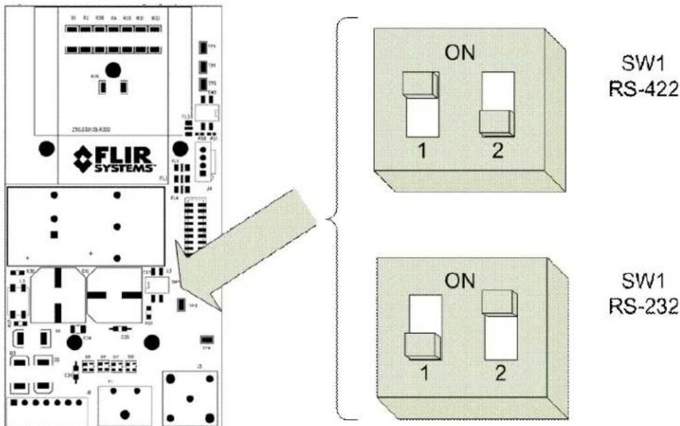
The serial protocol (RS-232 or RS-422) is configurable via a DIP switch on the cameras.
| Switch | On Off | |
| 1 Enables 100 ohm termination resistor (set to On for RS-422) | Removes termination resistor (set to Off for RS-232 communications) | |
| 2 | Enables RS-232 enable communication | Enables RS-422 communication |
Note: Daisy-chaining of cameras (point to multi-point configuration) is not supported and the termination resistor should always be enabled (On) for RS-422 and disabled (Off) for RS-232.
text_image
FLIR SYSTEMS SW1 RS-422 ON 1 2 SW1 RS-232Figure 4-2: Serial Communications DIP Switches
4.3 Camera Installation
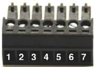
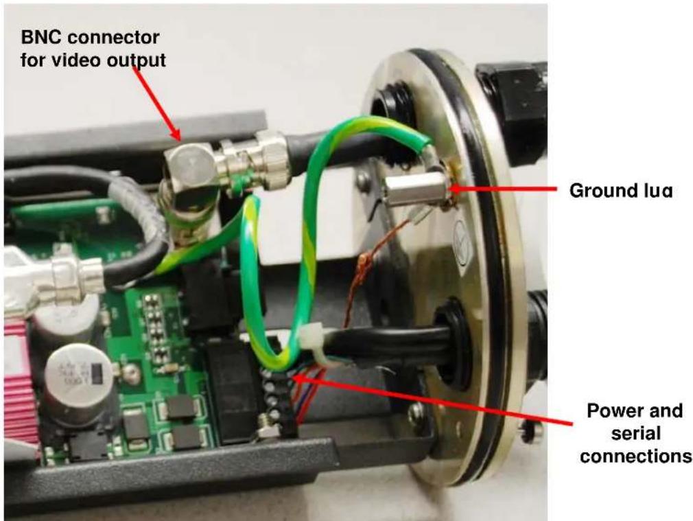
Instructions for connecting the power, video and communication leads to the camera are given below. The power and serial communication leads attach to a detachable connector which is inserted into a mating connector on the interface board, as shown in Figure 4-3: SR-Series Connections. The power and serial communication leads attach to the detachable connector according to Table 1: Power and Serial Pin Designations.
natural_image
Close-up of a black electronic component with seven pins (labeled 1 to 7) and no visible text or symbols on the body.Note: the pin numbers are not designated on the connector.
| Connector Pin | Used for Power or Serial Communications | DB-9 Comments | |
| 1 Serial 2 RS-422: Tx-; RS-232: Transmit Data (TD) | |||
| 2 Serial | 7 RS-422: Tx+ | ||
| 3 Serial 3 RS-422: Rx+; RS-232: Receive Data (RD) | |||
| 4 Serial | 8 RS-422: Rx- | ||
| 5 Serial | 5 Signal Ground | ||
| 6 Power Power DC- or AC neutral | |||
| 7 Power Power DC+ or AC line | |||
| Power Be sure to connect the ground to the lug inside the rear cover, as shown in Figure 3-2: Earth Ground Connection | |||
Table 1: Power and Serial Pin Designations
text_image
BNC connector for video output Ground lua Power and serial connectionsFigure 4-3: SR-Series Connections
Installation Steps
- Route the RG-59 video cable through the right-hand gland (when viewing from the rear) on the rear enclosure cover and crimp the connector to the end of the cable. Connect the cable to the BNC bulkhead connector.
- If necessary, set the SW1 DIP Switches according to the preferred RS-232 or RS-422 configuration.
- Make sure that the O-rings supplied on the front and rear covers of the camera enclosure are free of dirt and debris before reassembly. The O-rings are lubricated with silicone grease.
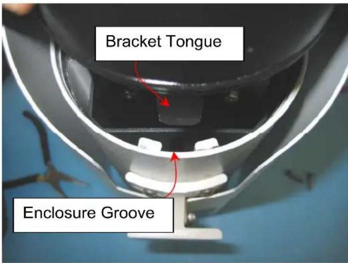
- Insert the SR Series camera assembly into the front of the enclosure aligning the tongue on the underside of the interface board bracket with the groove on the inside bottom of the enclosure, as shown in Figure 4-4. Press the two components together and ensure the O-ring is seated properly.
text_image
Bracket Tongue Enclosure GrooveFigure 4-4: Tongue and Groove Alignment
-
Secure the front cover to the enclosure using the included screws. If the ground cable inside the enclosure was disconnected, reconnect it to the ground lug on the rear plate of the enclosure. Connect the Earth Ground lead to the Earth Ground Lug on the inside of the rear of the enclosure (refer to Figure 3-2: Earth Ground Connection).
-
Insert the enclosure sled and rear plate into the enclosure body. Press the two components together and ensure the O-ring is seated properly. Secure the rear plate to the enclosure with the captive hex head screws.
-
Eliminate almost all of cable slack inside the enclosure. Now tighten the cable glands on the rear of the enclosure to create an appropriate seal.
5 OPERATING THE SR-SERIES THERMAL CAMERA
5.1 Advantages of Thermal Imaging
Originally developed for the military, thermal imaging cameras are now deployed in numerous commercial applications where it is impractical or too expensive to use active illumination (lights). They are perfect for wide-area surveillance in critical infrastructure or high-value residence installations where lighting is unwelcome or impractical. The cameras also provide improved daytime surveillance in environments where traditional CCTV security camera performance suffers, such as in shadows, backlit scenes or through foliage.
natural_image
Sunset over a road with large yellow light and silhouetted vehicles (no visible text or symbols)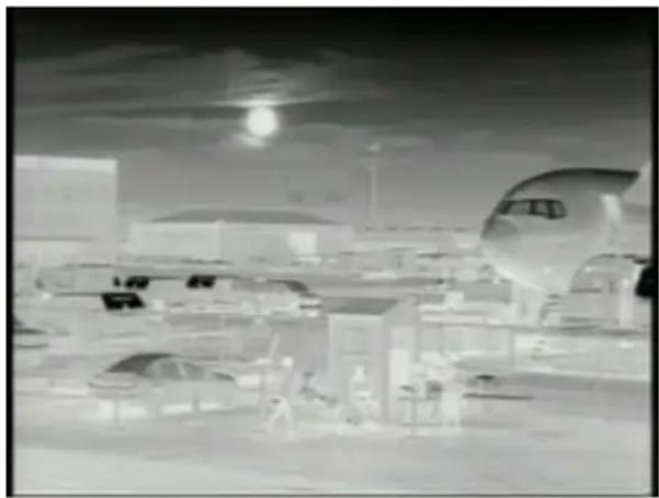
natural_image
Black-and-white industrial facility interior with aircraft and machinery (no visible text or symbols)Figure 5-1: Backlit daylight camera on left; thermal image on right
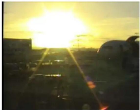
Observe that the setting sun in the backlit image on the left makes it difficult to discern any objects of interest; the thermal image on the right is not affected by the bright sun and therefore provides detail and contrast.
The SR-Series is designed to be a drop-in replacement for current systems employing daylight cameras. Initial setup of the system includes connecting power supply leads for the input power and a BNC cable for monitoring output video. Optionally, a serial cable can be connected to allow control of the camera settings.
5.2 Thermal Imaging
The SR-Series camera is a state-of-the-art thermal imaging system that will provide you with excellent night visibility and situational awareness, without any form of natural or artificial illumination. The SR-Series camera is easy to use, but you should take a moment to carefully read this section so you fully understand how to interpret what you are seeing on your display and how to use the controls.
natural_image
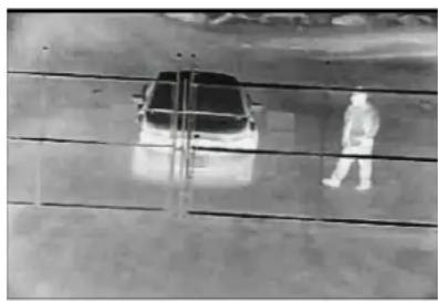
Aerial view of a person in protective suit walking alongside a car on a paved road (no visible text or symbols)While the imagery you will see on the monitor may at first look similar to ordinary black and white daylight video, as you get familiar with the camera you will appreciate the characteristics that make thermal imaging distinct. A few tips on how to interpret some of the imagery will help you to make the most of your system.
The thermal imager inside the camera does not sense light like conventional cameras; it senses heat or temperature differences. As you experiment with the system during daylight and nighttime operation, you will notice differences in the picture quality; this is normal. The camera senses small “differences” in apparent radiation from the objects in view, and, in white hot mode, displays them as either white (or lighter shades of gray) for warmer objects, and black (or darker shades of gray) for colder objects.
Your thermal imaging camera relies on the fact that all objects, even very cold objects like ice, emit thermal energy in the portion of the infrared spectrum that this camera can “see”, the long wave infrared (LWIR). Therefore, unlike an illuminated infrared camera, a thermal imaging camera does not need an additional active illumination source and images based on directly radiated rather than reflected energy.
This is why you will see hot objects such as exhaust stacks or vehicle engines that appear white (or black, or red depending on the video image mode selected), while the puddles of water and other cold objects appear dark (or cool). Scenes with familiar objects will be easy to interpret with some experience. The camera automatically optimizes the image to provide you with the best contrast in most conditions.
FLIR Systems, Inc. offers a comprehensive selection of training courses to help you to get the best performance and value from your thermal imaging camera. You can find out more at the FLIR training web page: http://www.flir.com/training.
5.3 Configuration and Control
Through a serial communications interface, there are various settings available to the user in order to optimize image quality for particular applications. These settings are accessible using a standard serial cable (refer to the appropriate installation section for cable pin outs). Note: The SR-Series cameras come pre-configured for RS-232 communication from the factory by default and the installer may change the communications to RS-422 via a DIP switch.
The SR-Series may be controlled by a PC running a Windows-based software application known as the FLIR Camera Controller GUI ^2 . For information on how to use the software, refer to the user guide included with the software. The software user manual and software updates are also available from the FLIR web site:
http://www.flir.com/cvs/cores/resources/
5.4 Flat Field Correction (FFC)
Periodically the image will momentarily freeze for a fraction of a second while the camera performs a flat field correction. A shutter activates inside the camera and provides a target of uniform temperature, allowing the camera to correct for ambient temperature changes and provide the best possible image. Through the software user interface, the frequency of the FFC can be modified and the FFC warning indication can be disabled.
6 CARING FOR YOUR SR-SERIES THERMAL CAMERA
Caution! Do not attempt to service the camera or make modifications to the camera core or electronics for any reason. Doing so can cause permanent damage and will void the warranty.
Your SR-series camera images through a lens that is made from material that is transparent to long-wave infrared energy. This lens is designed for the harsh outdoor environment and has a coating for durability, but may require occasional cleaning. FLIR Systems Inc. suggests that you clean the lens when image quality degradation is noticed or excessive contaminant build-up is seen on the lens.
The camera housing has a durable coating and the rugged protective window is designed to withstand normal cleaning. Rinse the camera housing with low pressure fresh water to keep it clean. If the front window of the camera gets water spots, wipe it with a clean soft cotton cloth dampened with fresh water. If the window requires further cleaning, use a soft moist cotton-based cloth with isopropyl alcohol or dish soap.
Do not use abrasive materials, such as paper or scrub brushes as this will possibly damage the lens by scratching it. Only clean the lens when you can visually see contamination on the surface.
6.1 Temperature
The SR-Series camera has an operating temperature range of -40 to 55°C. Choose an installation location so that the camera is not subject to temperature extremes that exceed this range. Do not expose the camera to direct sun without the sun shroud installed.
6.2 Maintenance
If you have a problem with your thermal camera, do not attempt to repair it yourself. The SR-Series camera core is a sealed unit and cannot be opened or serviced in the field. Consult your installation dealer or FLIR Systems Inc. for repair information.
Lens Cleaning
Materials:
Optical-grade tissue (e.g. Edmund Industrial Optics P/N 52105 or any similar product)
Pure water (de-ionized or other)
Isopropyl alcohol (IPA)
Saturate a piece of the lens tissue with the water and drape it over the lens. Let the surface tension of the water pull the tissue onto the lens surface and then drag the tissue across the lens surface. Repeat several times with different pieces of tissue.
Repeat the same step using IPA instead of water. Drag the final piece of tissue over the lens several times to prevent pooling, which could leave a residue behind.
7 TROUBLESHOOTING PROBLEMS
Video not displayed on monitor
If the camera will not produce an image, check the video connection at the camera and at your display. If the connectors appear to be properly engaged but the camera still does not produce an image, ensure that power has been properly applied to the camera and the fuse is not blown. Cycle power to the camera and listen for the FFC shutter to click. Absence of this sound is an indication of lack of power or a bad power board. If the camera still does not produce an image, have an authorized service representative make the appropriate repairs.
Noisy image
A noisy image is usually attributed to a cable problem (too small in diameter, too long, or inferior quality) or the cable is picking up electromagnetic interference (EMI) from another device. Although coax cable has built-in losses, the longer the cable is (or the smaller the wire gauge/thickness), the more severe the losses become; and the higher the signal frequency, the more pronounced the losses. Unfortunately this is one of the most common and unnecessary problems currently plaguing video security systems as a whole.
Cable characteristics are determined by a number of factors (core material, dielectric material and shield construction, among others) and must be carefully matched to the specific application. Moreover, the transmission characteristics of the cable will be influenced by the physical environment through which the cable is run and the method of installation. Use only high quality cable and be careful to match the cable to the environment (indoor or outdoor).
For long distance cable transmissions, consider using fiber optics, baluns, video amplifiers, or IP video encoders to improve the quality of transmission.
Image out of focus
The camera systems have a fixed-focus lens (focused at infinity at the factory) and the lens focus is not field-adjustable. Each camera has a minimum focus distance, as listed in the specifications section (SR-Series Camera Specifications). An out-of-focus object may be too close to the camera and within the minimum focus distance.
Image too dark or too light
By default the SR-Series cameras use an Automatic Gain Control (AGC) setting that has proven to be superior for most applications, but a particular installation may require an adjustment to the AGC settings. For example, a very cold background (such as the sky) could cause the camera to use a wider range than appropriate. Refer to section 5.3 Configuration and Control for information about how to make adjustments to the image generated by the camera. You may need to consider adjusting the AGC Region Of Interest (ROI) if the sky consumes a significant portion of your image, because the sky is considerably colder than most terrestrial temperatures.
Performance varies with time of day
You may observe differences in the way the camera performs at different times of the day, due to the diurnal cycle of the sun. Recall that the camera produces an image based on temperature differences. At certain times of the day, such as just before dawn, the objects in the image scene may all be roughly the same temperature, compared to other times of the day. Compare this to imagery right after sunset, when objects in the image may be radiating heat energy that has been absorbed during the day due to solar loading. Greater temperature differences in the scene generally will allow the camera to produce high-contrast imagery.
Note: Under conditions such as just before dawn when it appears the camera has low contrast due to many objects at roughly the same temperature (typically inanimate objects), a person or an animal walking through the scene during this time will be quite noticeable and cause the AGC to produce a high-contrast image.
Eastern or Western Exposure
Some users will choose to mount the camera pointing directly east or west, and this may cause the sun to be in the field of view during certain portions of the day. We do not recommend intentionally viewing the sun, but looking at the sun will not permanently damage the sensor. However, it may cause image anomalies and it may take some time for the camera to recover. The amount of time needed for recovery will depend on how long the camera was exposed to the sun. The longer the exposure, the longer the recovery time needed.
Image freezes
By design, the camera image will freeze momentarily on a periodic basis during the Flat Field Correction (FFC) cycle. Refer to section 5.4 Flat Field Correction (FFC) for more information about this. It is possible to change the interval used for FFC with the FLIR Camera Controller GUI; refer to the Tau User's Manual for more information.. The software is included in CD form with the SR-Series camera, but can also be downloaded at: http://www.flir.com/cvs/cores/resources/software/tau/.
8 SR-SERIES CAMERA SPECIFICATIONS
| Feature | Specification |
| Input Power See below | |
| Dimensions, Weight See below | |
| Sensor type Uncooled Microbolometer | |
| Spectral range 7.5 to 13μm | |
| Focal Length SR-304, SR-606 | 100 mm |
| SR-309, SR-612 50 mm | |
| SR-313, SR-618 35 mm | |
| SR-625 25 mm | |
| SR-324, SR-112 19 mm | |
| SR-334, SR-117 13 mm | |
| SR-348, SR-124 9 mm | |
| Minimum Focus ^3 SR-304, | SR-606 160 m |
| SR-309, SR-612 71 m | |
| SR-313, SR-618 26 m | |
| SR-625 13.1 m | |
| SR-324, SR-112 10 m | |
| SR-334, SR-645, SR-117 4.4 m | |
| SR-348, SR-124 2.1 m | |
| Pixel pitch | SR-1xx & SR3xx 25 μm |
| SR-6xx 17 μm | |
| Input power range 14V to 32VDC Voltages as measured at the input to the 18V to 27VAC electrical interface board. | |
| Fuse 4 Amp fast-blow mini blade fuseEx. Bussman BK/ATM-4 or equivalentDescription: FUSE - 4AMP, 32VOLT, BLADE TYPE | |
| Operating Temp. Range -40°C to 55°C (-40°F to 131°F) | |
| Storage Temperature -50° to 85°C | |
| Environmental Rating IP66 | |
| Lens Heater Thermostat controlled | |
| Analog video | NTSC or PAL (EIA-170 or CCIR 624, respectively). |
| Camera focus | Fixed focus (no adjustment needed) |
| Serial interface | RS-232, RS-422 (DIP switch configurable) |
| User Control | FLIR Camera Controller GUI (Windows-based software) |
Note: These specifications are subject to change without notice.
Warning! Proper ESD protocol should be followed while working inside the unit.
If the terminal block is removed during installation, be extremely careful to maintain the proper orientation when connecting the leads and reinserting the connector to the camera.
Warning! Do not connect leads or remove/reinsert the terminal block when power is active.
Input Power
The electrical interface board provides a screw-terminal jack for receiving 14 to 28 gauge tinned leads for input power. The following table describes the input power requirements at 25^ C. Peak ratings can occur in cold environments when the heater circuits on.
| Parameter Requirement True Power | Apparent Power | Comment | ||
| AC Input Voltage | 18 to 27 VAC | Voltage as measured at the input to the electrical interface board. | ||
| Nominal / Peak Current (TRMS) | 200 / 850 mA | 2.7 / 14 W | 5 / 21 VA | SR-645/-324/-334/-348 at 24 VAC |
| 200 / 850 mA | 2.7 / 14 W | 5 / 21 VA | SR-625 at 24 VAC | |
| 200 / 450 mA | 2.7 / 7 W | 5 / 11 VA | SR-618/-313 at 24 VAC | |
| 200 / 1.2 A | 2.7 / 17.3 W | 5 / 29 VA | SR-309/-612 at 24 VAC | |
| 200 / 2 A | 2.7 / 36 W | 5 / 48 VA | SR-606/-304 at 24 VAC | |
| DC Input Voltage | 14 to 32 VDC | Voltage as measured at the input to the electrical interface board. | ||
| Nominal / Peak Current (TRMS) | 100 / 410 mA | 2.41 / 9.8 W | SR-645/-324/-334/-348 at 24 VDC | |
| 100 / 410 mA | 2.41 / 9.8 W | SR-625 at 24 VDC | ||
| 100 / 240 mA | 2.41 / 5.8 W | SR-618/-313 at 24 VDC | ||
| 100 / 458 mA | 2.41 / 11 W | SR-309/-612 at 24 VDC | ||
| 100 / 980 mA | 2.41 / 25 W | SR-606/-304 at 24 VDC | ||
Table 2. Input Power Requirements
Note: The power measurements for the 160x120 models are similar to those of the SR-324, SR-334, and SR-348.
8.1 SR-Series Camera Dimensions
text_image
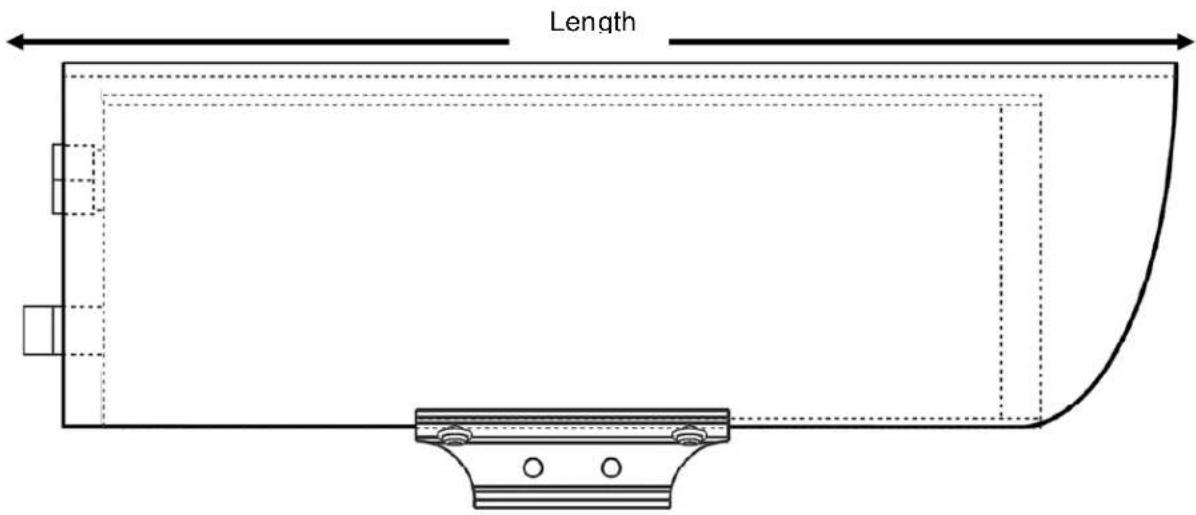
LengthFigure 8-1: Camera Side View
text_image
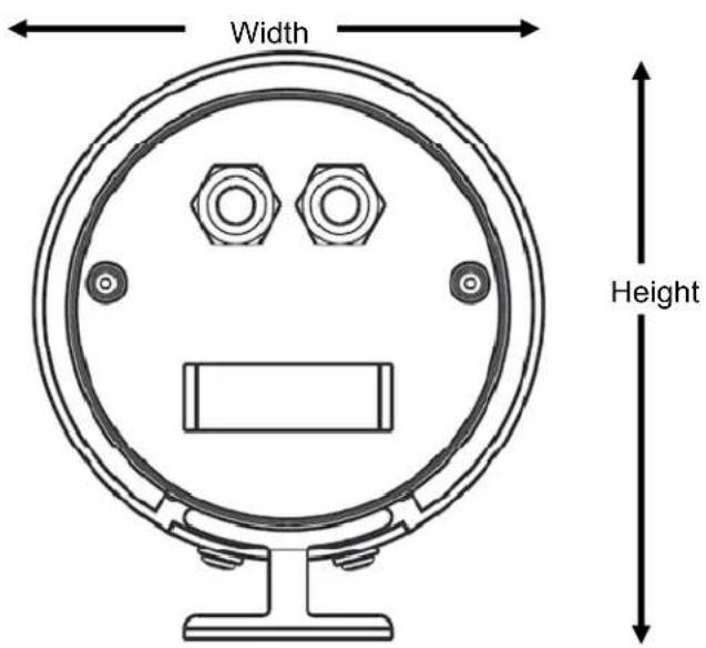
Width HeightFigure 8-2: Camera Rear View
| Dimension All cameras except SR-304 & SR-606 SR-304 & SR-606 | ||
| Length 10.5" (26.7) 15" (38.14) | ||
| Width 5.0" (12.7) 5.0" (12.7) | ||
| Height | 5.7" (14.4) | 5.68" |
| Weight 4.6 lb (2.1 kg) 6.5 lb (2.9 kg) | ||
Note: Values in parentheses are in centimeters, all others in inches.
text_image
4.00 (10.08) 2.00 (5.08) 1.00 (2.54) 1.00 (2.54) 2.00 (5.08)Figure 8-3: Enclosure Mounting Foot
9 REFERENCES
FLIR Standard Resolution Product Specification Document Number: 427-0014-00-09
FLIR Tau GUI User's Manual Document Number TAU-0035-00-10
Pelco EH2500 Series Enclosure Product Specification
NTSC EIA-170
PAL CCIR 624
MIL-STD-810E Environmental Testing
MIL-STD-188-124B, Grounding, Bonding and Shielding
IEC 60529 Degrees of protection provided by enclosures (IP Code)
IEC 60068-2-64, Environmental Testing Part 2 Vibration testing
Cenelec EN61326 CE Mark (Class A)
FCC Part 15; Subpart A EMI/EMC
Grounding Practices: IEEE Std. 1100 (The Emerald Book).
National Electrical Code, NEC-70-1996

FLIR
The World Leader in Thermal Imaging
Support
If you have questions that are not covered in this manual, or need more information, contact your local FLIR service representative or, 1 (877) 773-3547 inside the US.
In the US, you can reach FLIR Customer Support at (888) 747-FLIR (747-3547).