
EvoluX EX6000 iQ - Aspirateur piscine robotisé ZODIAC - Free user manual and instructions
Find the device manual for free EvoluX EX6000 iQ ZODIAC in PDF.


| Product Type | Robotic Pool Cleaner |
| Brand | Zodiac |
| Model | EvoluX EX6000 iQ |
| Dimensions (W x D x H) | 43 x 48 x 27 cm |
| Cleaner Weight | 9.5 kg |
| Packed Weight | 19 kg |
| Power Supply Input | 220-240 VAC, 50 Hz |
| Power Supply Output | 30 V DC, 150 W max |
| Cable Length | 18 m or 21 m (depending on model) |
| Filtration Type | All-purpose filter canister |
| Cleaning Modes | Waterline only (45 min), Quick Clean (1h15 min), SMART Cycle, Deep Clean (2h45 min) |
| Cycle Duration Range | 30 min to 3h30 (adjustable in 15-min increments) |
| Control Options | Control unit and iAquaLink app via Wi-Fi/Bluetooth |
| Lift System | Yes, for automated retrieval |
| Safety Features | RCD required (30mA), double insulation, automatic stop when not submerged |
| Maintenance | Clean filter after each cycle; replace brushes every 2 years or when wear indicator shows |
| Wear Parts | Brushes with wear indicator, tyres |
| Warranty | 3 years limited on motor block (or 1200 running hours), 1 year on filter canister |
| Manufacturer | Fluidra Group Australia Pty Ltd. |
| Included Accessories | Transport caddy (EX5000/6000 only), control unit, floating cable, manual, quick start guide |
Frequently Asked Questions - EvoluX EX6000 iQ ZODIAC
User questions about EvoluX EX6000 iQ ZODIAC
0 question about this device. Answer the ones you know or ask your own.
Ask a new question about this device
Download the instructions for your Aspirateur piscine robotisé in PDF format for free! Find your manual EvoluX EX6000 iQ - ZODIAC and take your electronic device back in hand. On this page are published all the documents necessary for the use of your device. EvoluX EX6000 iQ by ZODIAC.
USER MANUAL EvoluX EX6000 iQ ZODIAC
natural_image
Line drawing of a small robotic car with visible wheels and a handle (no text or symbols)EvoluX™ iQ
Robotic Pool Cleaner
EX4000
EX5000
EX6000
iAquaLink™ CONTROL
TYPE EC15---
WARNING
FOR YOUR SAFETY - For anything other than the routine cleaning and maintenance described in this manual, this product must be serviced by a pool technician who is licensed and qualified in pool equipment by the jurisdiction in which the product will be installed where such state or local requirements exist. In the event no such state or local requirement exists, the maintainer must be a professional with sufficient experience in pool equipment installation and maintenance so that all of the instructions in this manual can be followed exactly. Improper installation and/or operation will void the warranty.
Evolux Robotic Pool Cleaners are covered under a 3 Year Manufacturers Limited Warranty.
3 year manufacturers warranty or 1200 running hours on the motor block. Zodiac provides coverage until either yearly or total running hours figure is reached, whichever comes first. 1 year manufactures warranty on filter canister.
The 3 Year Limited Warranty Period starts on the date of purchase. Retain proof of purchase or note serial number for warranty claim.
To check running hours of the motor block, simply access “settings” (the cog in the upper right hand corner) via the iAquaLink app. Click through “info” and view “total running hours”.
THANK YOU FOR PURCHASING THE ZODIAC EVOLUX ROBOTIC POOL CLEANER.
YOUR ZODIAC ROBOTIC CLEANER HAS BEEN DESIGNED AND MANUFACTURED TO BE EASILY INSTALLED AND TO PROVIDE LOW MAINTENANCE OPERATION. PRIOR TO INSTALLING YOUR NEW ZODIAC CLEANER, PLEASE DO THE FOLLOWING:
1) Complete and return the warranty registration online at www.zodiac.com.au
2) Record your purchase information on the spaces provided below.
3) Attach your invoice (or a copy) to this page.
Should your product require repair under warranty, please contact Zodiac Customer Care 1300 763 021.
RECORD YOUR ZODIAC CLEANER DATA HERE:
Date of Purchase ____ Purchased From ____ Serial Number: ____
City ____ State ____ Post Code ____
Table of Contents
1 Important Safety Instructions .... 4
2 Cleaner Specifications.... 5
General Specifications.... 5
3 Assembly 6
Contents 6
Assemble the Transport Caddy 6
Attach the Control Unit to the Caddy....8
Connect to a Power Source.... 8
4 General Cleaner Operation....9
Install and Submerge the Cleaner....9
Control Unit....11
Start / Stop Cleaning and Adjust Cleaning Time..... 12
Lift System....12
5 Installing iAquaLink™ 13
Download the App 13
Sign Up and Log In....13
Configure the System.... 13
6 iAquaLink™ Control....14
iAquaLink™ Control Home Screen.... 14
Start / Stop Cleaning and Adjust Cleaning Time...... 14
Set Cleaning Mode....14
Remote Control 15
Program or Cancel Cleaning Schedules....15
Temperature Display 15
LED Lights....16
In-App Error Messages and Troubleshooting......16
System Settings.... 16
7 Maintenance 16
Cord Tangling 16
Clean the Filter Canister....17
Store the Cleaner When Not in Use 18
Replacing Wear Parts....19
Replacing Tyres.... 20
8 Troubleshooting....22
Error Codes 22
General Troubleshooting 23
Dismissing an Error Code.... 24
iAquaLink™ Troubleshooting 24
Common iAquaLink™ Troubleshooting 25
Conformity 26
1 Important Safety Instructions
Congratulations on purchasing the Zodiac Robotic Cleaner. Please read through the entire manual before installing your new robotic pool cleaner. Your cleaner must be installed and operated as specified.
WARNING
Failure to comply with the following warnings can increase risk of fire or electrocution which can result in property damage and serious injury, including loss of life.
PREVENT ELECTRICAL SHOCK
To reduce risk of electrical shock:
- The cleaner is to be installed in accordance with the relevant requirements of the Australian wiring rules AS/NZS 3000. Also refer to the installation instructions relating to the swimming pool equipment for which the cleaner will be an integral part. The cleaner is to be supplied through a Residual Current Device (RCD) with a rated residual operating current of 30mA.
- Do not enter pool while the robotic cleaner is in water.
- Do not bury cord. Locate cord so as to prevent it from being damaged by lawn mowers, hedge trimmers and other equipment.
- To reduce the risk of electrical shock, do not use the robotic cleaner or control unit if the cord is worn or damaged. Contact Zodiac Customer Care Service 1300 763 021 immediately for proper servicing and replacement of the damaged cord.
- Double insulation—For continued protection against possible electric shock, use only identical replacement parts when servicing. Do not attempt repair of the robotic cleaner, control unit, power cord, or floating cable.
- Use only the power supply provided with the product.
- NEVER OPEN CONTROL UNIT.
- DO NOT USE AN EXTENSION CORD TO CONNECT THE UNIT TO ELECTRIC SUPPLY; PROVIDE A PROPERLY LOCATED APPROVED ELECTRICAL OUTLET. THE CONTROL UNIT SHOULD BE PLACED NEAR THE APPROVED RECEPTACLE BOX.
PREVENT CHILD INJURY AND DROWNING
- To reduce the risk of injury, do not permit children or persons with reduced physical, sensory or mental capabilities, or lack of experience and knowledge to operate this product.
- Do not let anyone, especially small children, sit, step, lean, or climb on any equipment installed as part of your pool's operational system.
CAUTION
Failure to comply with the following warnings could cause damage to pool equipment or personal injury.
- The robotic cleaner must be installed and operated as specified.
- This product is intended for use with permanently-installed pools. Do not use with storable pools. A permanently-installed pool is constructed in or on the ground or in a building such that it cannot be readily disassembled for storage. A storable pool is constructed so that it is capable of being readily disassembled for storage and reassembled to its original integrity.
- Clean the filter canister in the Evolux cleaner after each use.
- Do not use the product in your pool if the water temperature is above 35ircC (95°F) or below 13ircC (55°F).
USE OF THE ZODIAC ROBOTIC CLEANER IN A VINYL LINER POOL
Certain vinyl liner patterns are particularly susceptible to rapid surface wear of pattern removal caused by objects coming into contact with the vinyl surface, including pool brushes, pool toys, floats, fountains, chlorine dispensers, and automatic pool cleaners. Some vinyl liner patterns can be seriously scratched or abraded simply by rubbing the surface with a pool brush. Ink from the pattern can also rub off during the installation process or when it comes into contact with objects in the pool. Zodiac Group Australia Pty. Ltd. is not responsible for, and the Limited Warranty does not cover, pattern removal, abrasion or markings on vinyl liners.
SAVE THESE INSTRUCTIONS
2 Cleaner Specifications
General Specifications
The general specifications for the cleaner are as follows:
| Control box [Y6W0]supply voltage | 220-240 VAC, 50 Hz; short circuit-proof safety isolating type |
| Supply voltage | 30 V DC |
| Installed load | 150 W max |
| Cable length | 18 M or 21M depending on model |
| Cleaner size (WxDxH) | 43 x 48 x 27 cm |
| Weight of Cleaner | 9.5 kg |
| Packed weight | 19 kg |
| Filtration | All-purpose filter canister |
| Cycle lengths | Variable programming. |
The cleaner is a double-insulated product. A double-insulated electrical appliance is one which has been designed in such a way that it does not require a safety connection to ground. The basic requirement for double-insulation is that no single failure can result in dangerous voltage becoming exposed so that it might cause an electric shock and that this is achieved without relying on an earthed (grounded) metal casing. This is achieved by having two (2) layers of insulating material surrounding live parts or by using reinforced insulation. Therefore, devices having double-insulated construction, such as this cleaner, do not utilize a grounded (three-prong) cord/plug.
3 Assembly
Contents
The packaging should contain the following items:
• Evolux cleaner and floating cable
- Control unit
- Manual, Quick Start Guide, and Warranty Card
- Transport and storage caddy (models: EX5000 and EX6000 only) Components (Figure 1)
a. handle frame
b. support blocks (x 2)
c. wheels (x 2)
d. wheel locking clips (x 2)
e. wheel axle / hubcap (x 2)
f. base unit
g. cleaner hook
h. caddy handle

Figure 1. Transport Caddy Assembly Components When unpacking the cleaner and its components:
- Check to make sure each component is in the box.
- Check cleaner and components for damage during transport.
- If there are any missing parts or damage, contact Technical Support at 1300 763 021.
Assemble the Transport Caddy
- Unscrew the handnut from the base (Figure 2).

natural_image
Technical line drawing of a mechanical component with a rotating knob and directional arrow (no text or symbols)Figure 2. Remove Handnut from Base Unit
- Insert the metal handle frame tubing into the base with notch end at the top, then rotate so the bends are away from you. (Figure 3).
- Push base down (Figure 3) so the metal handle frame is seated in the recess on the underside of the base.

natural_image
Diagram of a mechanical device with rotating arms and a handle, showing motion direction (no text or symbols)Figure 3. Connect Metal Frame to Base Unit
- Slide the handnut over the tube and twist to tighten onto base unit (Figure 4).

natural_image
Technical line drawing of a mechanical device with a lever and adjustment arrow (no text or symbols)Figure 4. Twist Handnut to Secure Frame
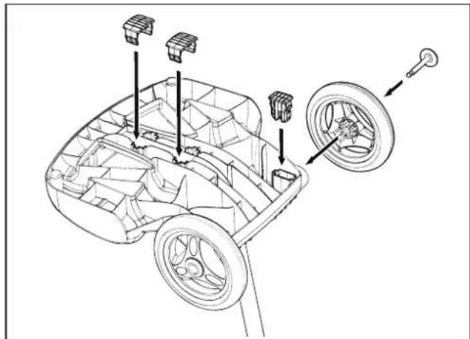
- Snap two (2) support blocks into place (Figure 5).
- Slide axle and hubcap piece through center of wheel and attach to base unit. Snap locking clip into place to secure wheel. Repeat to attach both wheels (Figure 5).
natural_image
Technical line drawing of a car interior showing components like wheels, seats, and a wheel (no text or labels)Figure 5. Snap in Support Blocks and Attach Wheels
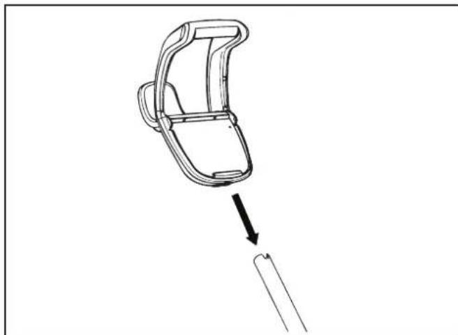
- Slide the control unit base / caddy handle attachment down over the metal tubing until it snaps into place. (See Figure 6).
natural_image
Line drawing of a mechanical component with an arrow indicating direction, no text or symbols presentFigure 6. Attach Caddy Handle
- Align cleaner hook pins with the top holes in the handle tube and snap into place (Figure 7).

Figure 7. Snap Cleaner Hook into Place
Attach the Control Unit to the Caddy
- Align the bottom of the control unit with the notch at bottom of the control unit hook on the caddy (Figure 8).

natural_image
Technical line drawing of a mechanical clamp or bracket assembly with a close-up view of the component (no text or symbols)Figure 8. Align Control Unit with Caddy Hook
- Press control unit onto the caddy hook until it snaps and locks into position (Figure 9).

natural_image
Line drawing of a mechanical clamp or clip assembly with an arrow indicating rotation (no text or symbols)Figure 9. Attach the Control Unit onto Caddy
Connect to a Power Source
WARNING
Failure to comply with the following warnings can increase risk of fire or electrocution which can result in property damage and serious injury, including loss of life.
PREVENT ELECTRICAL SHOCK
- Keep the control unit at least 3.5 m from the edge of the pool.
- The cleaner is to be installed in accordance with the relevant requirements of the Australian wiring rules AS/NZS 3000. Also refer to the installation instructions relating to the swimming pool equipment for which the cleaner will be an integral part. The cleaner is to be supplied through a Residual Current Device (RCD) with a rated residual operating current of 30mA.
- Do not use an extension cord to connect the control unit.
- Do not allow anyone to swim while the cleaner is in the pool.
-
The control unit is water-resistant, not water-proof. In order to prevent electrocution, never submerge the control unit or leave exposed to inclement weather.
-
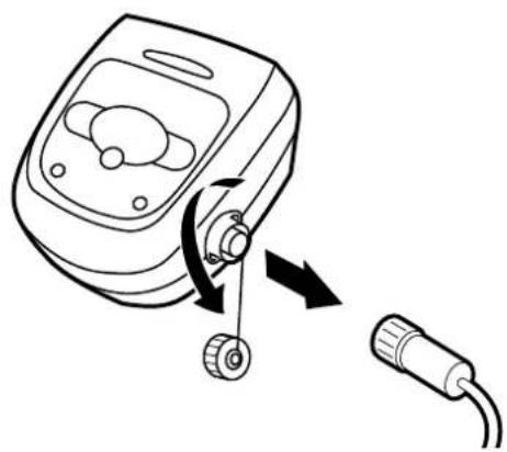
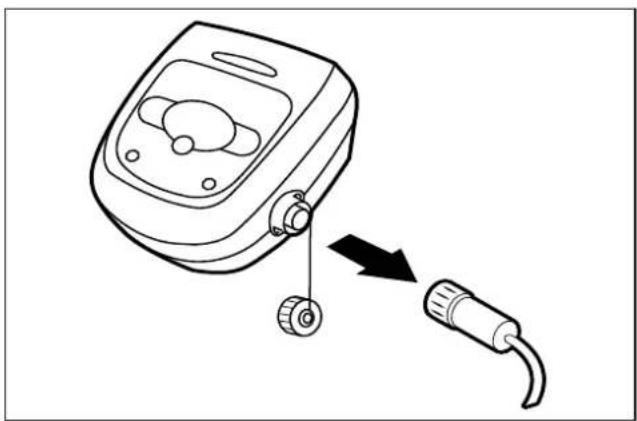
Unscrew the protective cap for the floating cable from the side of the control unit by turning counter-clockwise.
- Grip the notched end of the floating power cable, insert into the control unit, and turn clockwise to tighten. (Figure 10.)
natural_image
Line drawing of a medical device with a rotary knob and connected tubing (no text or symbols)Figure 10. Remove Protective Cap and Connect Power Cable
NOTE: To avoid damaging the power cable, do not try to twist the entire cable housing (see below).
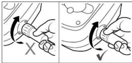
NOTE: To avoid exposing the power cable connector pins to water, be sure the connector is screwed in all the way and there is no gap (see below).

4 General Cleaner Operation
CAUTION
To prevent damage to the cleaner, be sure to adhere to the following guidelines:
- Remove the cleaner from the pool after the cleaning cycle is completed.
- Store on the caddy out of direct sunlight or inclement weather.
- Never lift the cleaner out of the pool by the floating cable. Always use the lift feature to remove cleaner from the pool.
• Take additional care when lifting the cleaner out of the pool. It becomes heavier when filled with water.
• Always remove the cleaner from pool when super chlorinating or adding acid.
- Do not handle cleaner while it is in operation
IMPORTANT
• Always make sure the cleaner head is fully submerged before you begin operation.
- Clean the filter canister after each cleaning cycle.
- Do not leave your cleaner in the pool on a permanent basis.
- At the end of each cycle, remove the cleaner from the pool.
- Start at the cleaner head and untangle any coils in the cable before storing the cleaner.
The Evolux robotic cleaner includes a safety feature that automatically stops the cleaner if it is powered on but not submerged in water. For pools equipped with a beach area, this safety feature is programmed to drive the cleaner in reverse and back into the pool when the impeller is out of the water.
Zodiac recommends not exceeding 3 cleaning cycles per week.
Install and Submerge the Cleaner
- With the control box plugged into a power outlet, spread the floating cable across the pool deck until you reach the middle of the pool length.
- At the center point, submerge the cleaner in the pool and hold in the vertical position to release any air trapped inside. (Figure 12).

natural_image
Illustration of a hand holding a small device with a downward arrow labeled '1' (no text or symbols on the device itself)Figure 11. Submerge the Cleaner Vertically
- Ensure the unit sinks to the bottom of the pool and does not float (Figure 13).

natural_image
Illustration of a mechanical device with a numbered label '2' and internal components (no readable text or symbols)Figure 12. Cleaner Sinking to the Bottom of the Pool
- Place only enough floating cable in the water to reach the farthest end of your pool from the central point. Spread out the floating cable ensuring there are no kinks or coils in the cable (Figure 13).

flowchart
graph TD
    A["cleaner"] --> B["cadder / control unit"]
    B --> C["Recommended entry point"]
    C --> D["Max Floating Cable Length"]
    D --> E["Not Recommended"]
    style A fill:#f9f,stroke:#333
    style B fill:#ccf,stroke:#333
    style C fill:#cfc,stroke:#333
    style D fill:#fcc,stroke:#333
    note right of C: "Recommended entry point"
    note right of D: "WARNING: Do not use an extension cord"
Figure 13. Pool Entry Point for Optimal Patterning
Control Unit
The control unit can be used to initiate basic cleaning features and to connect the device to home Wi-Fi. For more information on connecting your cleaner to Wi-Fi, see section 5, Installing iAquaLink™.

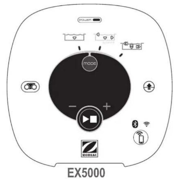

Button Functions

Control unit is receiving power

Start/Stop cleaning

Select cleaning mode:

Waterline only (45 min)

Quick Clean (1h 15 min) Floor only

SMART Cycle (Calculate custom clean duration) Floor, Wall, Waterline

Deep Clean (2h 45 min) Floor, Walls, Waterline, High Intensity

Dirty canister indicator

Remove cleaner from the pool

+ / - 15 minute increments

Initiate connection and set up iAquaLink™ control

Bluetooth connection status: BLINKING - searching for signal SOLID - paired with phone

Wi-Fi connection status: BLINKING - connected to router SOLID - connected to the internet
Start / Stop Cleaning and Adjust Cleaning Time
The factory default cleaning mode is SMART Cycle (Floor, Wall, Waterline).
Cycle calculates a customized cleaning time optimized for your pool. On the first run of SMART Cycle, the control box counts up from zero as it calculates the optimized cleaning time.
On periodic SMART Cycle cleaning, the control box will count down from the optimized cleaning time.
To recalculate the SMART Cycle setting, press and hold the position for 5 seconds.

Use mode change cleaning surface setting. Toggle between:

Waterline Only n)

Quick Clean (5 min) Floor only

SMART Cycle lates custom cleaning duration) Wall, Waterline

Clean min)
(2h 45 min)
Floor, Wall's, Waterline, High Intensity
*Not available on all models
With the cleaner submerged in the water, press to begin operation.
Press again to interrupt and cancel an in-progress cleaning cycle.
NOTE: The control box automatically goes into standby mode after 5 minutes and the display screen turns off. Press any key to exit standby mode and view remaining cycle time. Cleaner will continue to function in standby mode.
Press +/- buttons to increase or decrease cleaning time in 15-minute increments.
- Minimum run time is 30 minutes
- Maximum run time is 3 hours 30 minutes
Lift System
The Lift System is designed to assist in retrieving the robot from the pool. Lift System can be activated at any time during or after a cleaning cycle.
- Press to begin the automated procedure. The screen displays Lift System is in operation.
NOTE: To stop the procedure at any time, press and release the button again.
-
Next, Press and HOLD to rotate the cleaner.
-
Once the cleaner is facing the wall of your choice for retrieval, release the button.
-
Cleaner will drive forward and up the wall it is facing. It will wait at the water line to be retrieved.
-
When in reach, remove the cleaner from the pool using the handle. The cleaner will quickly expel water to allow for lighter, easier removal.
NOTE: Never lift the cleaner out of the pool by the floating cable.
5 Installing iAquaLink™

The iAquaLink app is available for download from the App Store or Google Play.
With iAquaLink Control, you can connect to your robotic cleaner from anywhere, anytime to access many functions and troubleshooting advice. App features are dependant on model.
Before you begin installation, make sure you have the following:
- Robotic Cleaner submerged in the pool.
- Control Box connected and plugged into a GFCI outlet.
- Smart device (phone or tablet) with Wi-Fi and Bluetooth enabled
- Wi-Fi router with sufficient signal strength at the Control Box
- IMPORTANT: Have your Wi-Fi network password available.
Download the App
Install or update the iAquaLink app from the App Store or Google Play.
Once the download is complete, select the iAquaLink icon on your smart device to open the app.
Sign Up and Log In
Open the iAquaLink app, then Sign Up or Log In.
Complete all required fields in the Account Set Up page and agree to the Terms and Conditions.
Configure the System
- On the My Systems page, click + in the upper right-hand corner to add a system.
- Choose "Robotic Cleaner" from the list and choose your model type.
- On the Control Box, press Bluetooth light indicates status:
BLINKING - searching for signal
SOLID - paired with phone
- Follow on-screen prompts to add your cleaner and connect to your home router.
Wi-Fi light indicates status:
BLINKING - connected to router
SOLID - connected to the internet
NOTE: The searching screen may take a few minutes to find your router. If you receive an error you may have a weak router signal at the location of your control box OR you may have entered an incorrect Wi-Fi password. In the case of a weak router signal, consider installing a Wi-Fi extender to boost your signal strength. (See iAquaLink Troubleshooting section.)
6
iAquaLink™ Control
Once you have downloaded the iAquaLink app and connected the device to Wi-Fi, the iAquaLink app allows for robotic cleaner control from anywhere, anytime. Functions vary within the iAqualink app depending on which cleaner model you have.

WARNING
Do not enter pool while the robotic cleaner is in water.
iAquaLink™ Control Home Screen
App function and design is subject to change.
NOTE: To recalculate SMART Cycle, go to the Set Cleaning Mode after the initial calculation.
-
From the Home screen or the Control Box press the Start/Stop button to begin cleaning.
-
The app displays the cycle time in hours and minutes.
To increase or decrease the cycle time during cleaning, press the (+) and (−) buttons.
-Time adjusts up or down in 15 minute increments.
-Minimum run time is 30 minutes.
-Maximum run time is 3 hours 30 minutes.
-The control box displays the same countdown and cycle setting as the app.
- Press ☐ to interrupt and cancel an in-progress cleaning cycle.

Start/Stop Cleaning

Dirty Canister Indicator

Remote

Manual Time Adjustment (current run time +/- 15 minutes)

Clean Mode
°C / F
Water Temperature Display (model EX6000 only)

Lift System
Start / Stop Cleaning and Adjust Cleaning Time
The factory default cleaning surface setting is SMART Cycle (Floor, Wall, Waterline).
SMART Cycle calculates a customized cleaning time optimized for your pool. On the first run of SMART Cycle, the app counts up as it calculates the optimized cleaning time.
On periodic SMART Cycle cleaning, the app will count down from the optimized cleaning time.
Set Cleaning Mode
- From the main screen, select Cleaning Mode to view options.
- Choose from available cleaning modes depending on your cleaner model.
*3. In Custom mode (if applicable), select the cleaning surface and cleaning intensity from the on-screen icons.
* not available on all models
Remote Control
Use your mobile device as a remote control.
IMPORTANT: Only use Remote Control when in view of the cleaner.
- From the main screen, select the Remote tab.
NOTE: When in remote control mode, the control box
displays

- You can direct the cleaner using the remote control or use the spot clean feature (not available on all models) to help pick up debris.
*3. To use Spot Clean, drive the cleaner near where debris has collected and initiate "Spot Clean". The cleaner will perform a short cleaning pattern to remove debris in that area.
* not available on all models
NOTE: If you notice significant delays in response time, check your Wi-Fi connection status and signal strength.
Lift System
The Lift System is designed to assist in retrieving the robot from the pool. Lift System can be activated at any time during or after a cleaning cycle.
IMPORTANT: Only use Lift System when in view of the cleaner.
-
From the main screen, select Lift System to enter automated procedure.
-
Use the left and right arrow icons to rotate the cleaner to face the wall of your choice.
-
Press the Lift System icon to drive the cleaner up the wall it is facing. The cleaner will wait at the water line to be retrieved.
NOTE: To stop the procedure at any time, press and release the button again.
- When in reach, grab the cleaner handle and begin to pull cleaner out of the water. The cleaner will quickly expel water to allow for lighter, easier removal.
NOTE: Never lift the cleaner out of the pool by the floating cable.
Program or Cancel Cleaning Schedules (not available on all models)
It is still recommended to remove and clean the filter canister after every cleaning cycle.
-
Tap the area titled Next Cleaning or go to System Settings and choose Schedules.
-
To program a schedule, select the day of the week.
-
Select a start time to begin the cleaning cycle.
-
Select a cleaning mode. Mode selected will determine runtime.
-
Press OK to save the schedule or Delete to remove permanently.
-
Repeat steps 2-4 to program additional days.
NOTE: Only one programmed cleaning cycle can be scheduled per day.
-
Press BACK or DONE to leave the Edit Schedule page and return to the main screen.
-
The next scheduled cleaning cycle will display near the top of the main screen.
Temperature Display (not available on all models)
On some models, the pool water temperature will be displayed on the main app screen. Accurate temperature may take a few minutes to display as the sensor acclimates to the surrounding water temperature. Temperature will only be displayed during an in-progress cleaning cycle.
LED Lights
The Sensor Nav System™ LED is located on the front of the cleaner. This light indicates status, either:
Blinking Blue - Sensing, Scanning and Cleaning
Solid Blue - Cleaning
Blinking Green - Lift System or Spot Cleaning
Solid Green - Remote Control
On some models, an LED light illuminates the interior area of the body and canister.
NOTE: LED lights may be difficult to see in sunlight.
In-App Error Messages and Troubleshooting
If an error occurs, the status bar will show a warning symbol and: "Cleaning Interrupted".
- Click on the warning symbol to view troubleshooting advice on how to fix the issue.
- Choose Clear Error if you believe you have fixed the problem and want to re-try. Choose OK if you want to suspend the cleaner in error mode and work on the troubleshooting fix at a later time.
System Settings
Access System Settings by pressing the gear icon in the upper right hand corner of the app screen.
7 Maintenance
WARNING
To avoid electric shock and other hazards which could result in permanent injury or death, disconnect (unplug) the cleaner from the power source before performing any cleaning and maintenance.
Cord Tangling
Tangling can occur more frequently when the cleaner is not attended to after each cleaning cycle. The tangle-reducing swivel, in addition to proper installation, general maintenance and the following troubleshooting steps can help to avoid cable challenges.
IMPORTANT
Cleaner power cable may become tangled if correct procedure is not followed after each cleaning cycle.
NOTE: For optimal patterning and reduced tangling, the floating cable should enter the water near the middle of the pool length. Only place enough cable in the water to reach the farthest point in the pool.
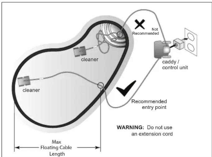
Figure 14. Optimal Entry Point in Pool
If tangling occurs, follow these steps:
-
Remove the cleaner from the pool using the Lift System. When the cleaner is within arm's reach, use the handle to remove from the water. Never lift the cleaner out of the pool by the floating cable or swivel.
-
Hold the cleaner vertically to drain.

natural_image
Line drawing of a person standing on a boat with water droplets falling, no text or symbols presentFigure 15. Keep Cleaner Vertical to Drain Water
- Unplug power to the cleaner at the control box.
natural_image
Line drawing of a medical device with a connector and cable, showing a change in the cable (no text or symbols present)Figure 16. Unplug
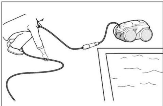
- Remove the cleaner from the pool and untangle all kinks and coils in the power cable. Start at the cleaner head. Lay the cable in the sun to loosen any tangling memory.
natural_image
Line drawing of a hand holding a cable connected to a small robotic device, with no visible text or symbols.Figure 17. Untangle
Clean the Filter Canister
The filter canister should be cleaned at the end of each cycle.
-
Remove the cleaner from the water using the Lift System and let the remaining water drain.
-
Set the unit on four wheels.
-
Push the cover lock (1) and lift the cover (2) until it is secured in the vertical position.

Figure 18. Lift Cleaner Cover
- Remove the filter canister assembly from the body (3).

natural_image
Line drawing of a lawn mower with a hand adjusting the seat cover (no text or symbols)Figure 19. Remove Filter Canister Assembly
- Push the quick release button on the canister assembly (4) and pull open.

Figure 20. Open Filter Canister Assembly
- Separate the filter canister from the filter support (6).

natural_image
Illustration of hands assembling a battery pack with a 6-inch arrow indicating the process (no text or symbols present)Figure 21. Remove Filter Canister
- Empty all debris from the filter canister, then rinse the canister, the filter support and the cleaner using a hose.

natural_image
Line drawing of a hand pouring liquid into a container with a bag attached (no text or symbols)Figure 22. Wash Filter Canister
NOTE: Periodically, remove the filter canister and clean thoroughly with soapy water and a soft bristle brush.
Store the Cleaner When Not in Use
The cleaner should be cleaned regularly using slightly soapy clean water. Do not use solvents such as trichlorethylene or its equivalent. Rinse the cleaner generously using clean water. Do not let your cleaner dry in direct sunlight near the pool. The cleaner should be stored on its caddy so that it dries quickly.
-
Disconnect cleaner from the power source.
-
Starting at the cleaner head, remove all coils and tangles from the cable. Lay the cable in the sun to loosen any tangling memory.
-
Place the rear wheels on the caddy and position the cleaner vertically on the caddy base.
-
Disconnect the cable from the control box. Replace the protective cap on the control box.

natural_image
Line drawing of a person using a handheld device connected to a robotic car (no text or symbols present)Figure 23. Untangle the Floating cable
- Loosely coil the power cable starting at the cleaner and moving toward the connection point at control box. Store the cable by wrapping it around the hook located on the front of the caddy.
Replacing Wear Parts
Replacing Brushes
The cleaner is fitted with PVC brushes with a "wear" indicator.
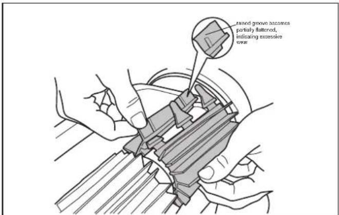
Figure 24. Worn Brush Indicator
To maintain cleaner performance at its best you need to replace the brushes as soon as one of the wear indicators is reached (even if the blade wear is not even). It is recommended that you replace the brushes when the rubber is worn down to the top of the wear indicator (or every two years, whichever comes first).
To replace a worn brush:
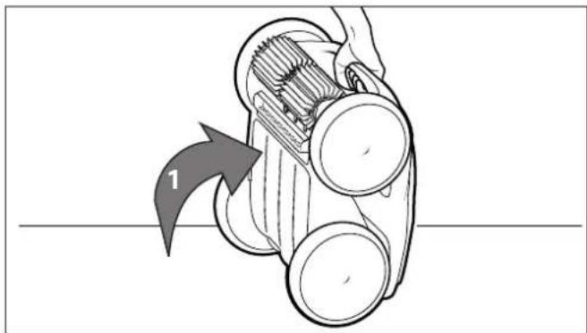
- Lift the cleaner to a vertical position so that the handle is up (Figure 26).
natural_image
Diagram of a mechanical device with a numbered arrow indicating direction (no text or symbols present)Figure 25. Cleaner in Upright Position
- Separate the edges of the brush and undo the tabs. Remove the worn brushes.

natural_image
Illustration of hands installing or adjusting a mechanical component with a numbered arrow (no text or symbols present)Figure 26. Undo the Tabs of the Brush
- To install the new brush, position the new brush on the roller with the cleaning blades facing away from the roller.
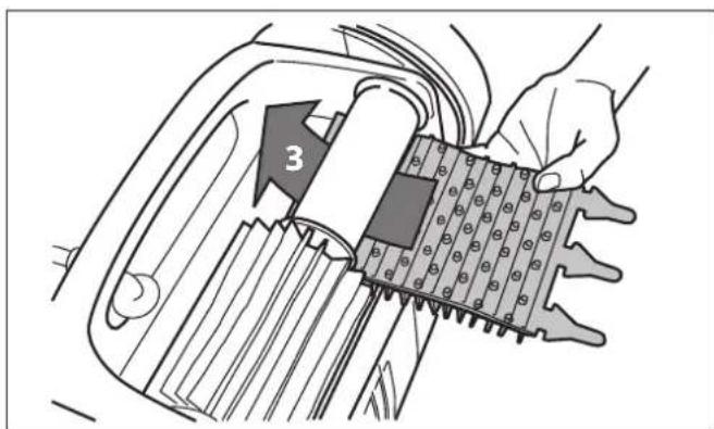
Figure 27. Install the New Brush
- Thread each tab into the slot provided and gently feed it through until the heel comes out at the other side of the slot.

Figure 28. Pull Tabs Through Each Slot
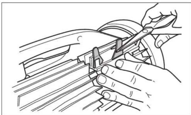
- Use a pair of scissors to cut the tabs 3/4 inch from the heel so that they are no higher than the cleaning blade.
- Repeat the procedure to install the second brush.
natural_image
Line drawing of hands using a tool to adjust or install a mechanical component (no text or symbols present)Figure 29. Cut Tabs
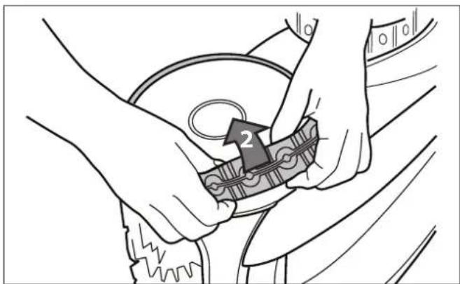
Replacing Tyres
- Pull on the inside of the old tyre to remove the tire lip from the wheel

natural_image
Line drawing of hands operating a car wheelbell with a belt clamp (no text or symbols)Figure 30. Pull the Old Tyre Over the Wheel
- Remove the old tyre.
natural_image
Illustration of hands assembling a mechanical component with a numbered arrow (no text or symbols)Figure 31. Remove the Old Tyre
- To replace the tyre, position the tyre on the wheel making sure to orient the tyre so that the word INSIDE is toward the body of the cleaner.

Figure 32. Tyre Replacement Orientation
- Push one side of the tyre on to the wheel and fit the rib of the tyre in the groove of the wheel.

natural_image
Illustration of hands cleaning a circular object with a knife, no text or symbols presentFigure 33. Start on One Side of the Tyre
- Work the tyre onto the wheel and verify the rib of the tyre is positioned properly within the groove of the wheel.

natural_image
Illustration of hands performing a sewing or sewing motion on a circular object, with no visible text or symbols.Figure 34. Work the Tyre On Around the Wheel
- Push and position the rib of the inner side of the tyre in the groove of the wheel. If needed, turn the wheel gently to help with installation.

natural_image
Illustration of hands adjusting a mechanical component with arrows indicating motion (no text or symbols)Figure 35. Push the Tyre into Place on the Wheel
8 Troubleshooting
Information about the cleaner status and any relevant condition will be displayed on the control unit and/or in the iAquaLink™ app.
Error Codes
| Control Unit Display | In-App Display | Suggested Solution |
| 1 | Pump Motor | a. Check for corrosion or bent pins in the floating cable connection area. |
| 2 | Traction Motor Right | b. Turn each wheel one quarter turn in one direction repeatedly until rotation is smooth. Repeat, turning wheels in the opposite direction until rotation is smooth. |
| 3 | Traction Motor Left | c. If this does not resolve the problem, contact your local retailer for a diagnostic review or call customer service. |
| 4 Pump Motor Consumption | a. Check for small debris or hair in the fan impeller.b. Thoroughly clean the filter canister.c. If this does not resolve the problem, contact your local retailer for a diagnostic review or call customer service. | |
| 5 | Drive Motor Consumption Right | a. Thoroughly clean the filter canister.b. Turn off the cleaner and submerge. Shake to release air bubbles. Restart cycle. |
| 6 | Drive Motor Consumption Left | c. If this does not resolve the problem, contact your local retailer for a diagnostic review or call customer service. |
| 7 Cleaner | Floating | • Turn cleaner power off, then submerge cleaner according to correct procedure. |
| 8 Cleaner | Out of the Water | • Turn off the cleaner and submerge. Shake to release air bubbles. Restart cycle. |
| 9 N/A | • Cleaner has completed a cleaning cycle. This is not an error. No action required. | |
| 10 Communication | a. Turn cleaner power off and on again to reset.b. Check floating cable connection to the control unit. Check for corrosion or bent pins at the connection point.c. If this does not resolve the problem, contact your local retailer for a diagnostic review or call customer service. | |
| N/A Connection Error | a. Check that the control unit is plugged into an approved power outlet and that the LAN/WEB icons on the box are illuminated.b. If not, go through the set-up steps to reconnect to the home router or press the Wi-Fi to Phone button to connect the system in 15-minute Wi-Fi to Phone mode.c. Check that the router is in close enough range to the control unit. Install a Wi-Fi extender if necessary. | |
General Troubleshooting
The following list provides some helpful hints for troubleshooting common challenges when using the cleaner.
| User Issue Possible Cause Suggested Solution | ||
| Lights on control unit flash after pressing Start/Stop | Floating cable not connected Unplug and then reconnect the floating cable to the control unit. | |
| Cleaner not fully submerged. Remove cleaner from pool and re-submerge (see Install and Submerge the Cleaner). | ||
| Poor connection or need to restart cycle. | Unplug the control unit and reconnect to an approved power outlet. Press "Start" to begin a new cycle. | |
| Propeller or wheels may be jammed and not turning correctly. | Contact your local retailer to request a diagnostic review. If the problem is not resolved, contact Zodiac Customer Care at 1300 763 021. | |
| The flashing lights appear on the control unit during the cleaning cycle. | Cleaner not fully submerged Remove cleaner from pool and re-submerge (see Install and Submerge the Cleaner). | |
| The cleaner does not stay on the pool surface or is floating excessively. | There is air trapped inside the cleaner housing. | Remove cleaner from pool and re-submerge (see Install and Submerge the Cleaner). |
| The filter canister is full or dirty. Dispose of debris and thoroughly clean the filter canister with mild soap and a soft brush. Then, re-submerge the cleaner (see Clean the Filter Canister). | ||
| The cleaner is not climbing walls. | The filter canister is full or dirty. Dispose of debris and thoroughly clean the filter canister with mild soap and a soft brush. Then, re-submerge the cleaner (see Clean the Filter Canister). | |
| Tyre treads worn down See Replacing Wear Parts | ||
| Confirm appropriate pool chemistry Speak with your pool service professional. Do not leave cleaner in the pool during any chemical treatments. | ||
| The cleaner is not moving Not connected to electricity. The outlet the control unit is connected to, is not supplying electrical power. Check that the outlet to which the control unit is connected is receiving electricity. | ||
User Issue Possible Cause Suggested Solution
| The cleaner is not cleaning the pool effectively. | Filter canister is full or dirty. Dispose of | debris and thoroughly clean the filter canister with mild soap and a soft brush. Then, re-submerge the cleaner (see: Clean the Filter Canister). |
| Brushes are worn. Check the wear indicator(s). Contact your local dealer for spare parts. | ||
| Cable is excessively tangled. Untangle | the twisted cord and lay in sun to reduce memory. (See: Cord Tangling). | |
| Pool temperature reading from the cleaner (certain models only) is different to the temperature reading shown in the iAquaLink app or other equipment. | The cleaner reading is taken from the bottom of the pool. Deeper water will be colder than at the waterline. | Take an average of the two readings to approximate current pool water temperature. |
Dismissing an Error Code
From the Control Unit:
After you have completed the troubleshooting solution steps, press any key (except the phone icon) to clear the error code.
If the control unit is in Standby Mode, press the Start/Stop button to show the on-screen display. After you have completed the troubleshooting solution steps, press any key (except the phone icon) to clear the error code.
From the iAquaLink™ App:
Press the error icon to display troubleshooting solutions. After you have completed the troubleshooting solution steps, press Clear Error to return to normal operation. Or, press OK if you need to complete the solution steps at a later time.
iAquaLink Troubleshooting
This information can help to troubleshoot connection and setup challenges between the iAquaLink app and the cleaner.
How It Works
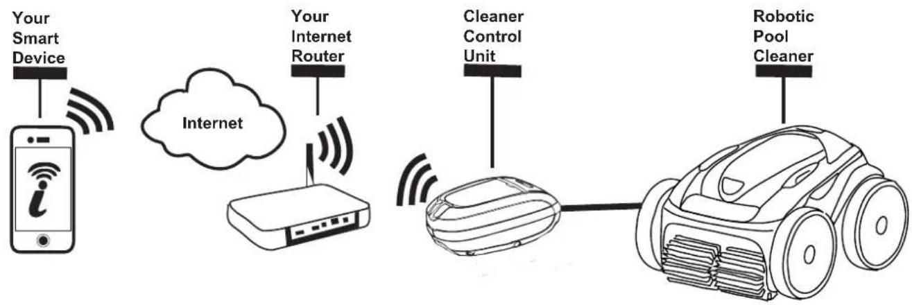
flowchart
graph LR
    A["Your Smart Device"] --> B["Internet"]
    B --> C["Your Internet Router"]
    C --> D["Cleaner Control Unit"]
    D --> E["Robotic Pool Cleaner"]
How to connect:
You must connect to the home router (network) by first establishing a direct connection between the control box and your smart device. (See: Configuring the System.)
IMPORTANT: It is recommended to locate the control box as close to the home router as practical. Do not use an extension cord.
Common iAquaLink™ Troubleshooting
Remember, if you get a new Wi-Fi Router, reset the defaults of your current Wi-Fi Router or simply change your Wi-Fi network password, you will have to re-establish the connection between your cleaner and the router. (See: Configure the System.)
| User Issue Possible Cause Suggested Solution | ||
| All lights are off Bright sunlight | Shield the lights to block sunlight and re-check if the lights are lit. | |
| Control box is unplugged. Plug the control unit in. (See: Connect to a Power Source). | ||
| Power outage. Verify that the breaker is on and electricity is being supplied to the outlet. | ||
| Lost internet connection. Check internet connection - Network may be down. | ||
| Wi-Fi is off Router is off. Turn | router on. | |
| Router password was changed. Reset router with new password. | ||
| Wi-Fi light is flashing Lost internet connection | Internet connection Check internet connection - Network may be down. | |
| Control box is too far from home router | Relocate the control box as near to the home router as practical. (See: Install and Submerge the Cleaner) Do not use an extension cord. | |
| Weak Wi-Fi signal · Check for adequate Wi-Fi signal strength.· With a Windows laptop, go to Network Connections in the Control Panel. Check Signal Strength meter under Wireless Network Connection icon while standing near the control box.· With a smart device, search for, download, and use an app that can check signal strength while standing near the control box. If Wi-Fi signal is weak, consider installing a Wi-Fi extender. | ||
| Connectivity issue with local Wi-Fi or connection to the server. | Contact your local internet service provider.· Unplug your control box and wait 10 seconds. Plug in the box again and see if lights illuminate.· Check Internet connection - Network may be down. | |
| Antenna firmware update in progress. | Flashing may continue up to ten minutes until update is complete. | |
| Wi-Fi light is on but buttons and functions are disabled | Firmware update in progress | PROG displays on the control unit and information is displayed in the app during an over-the-air firmware update. Wait for button functions to resume after update is completed. Do not unplug from power during an update. |
Conformity

EU
IEC 60335-2-41
Intertek
3145455L100001-01A

87 002 641 965-
The manufacturer reserves the right to modify these specifications without notice. Although the cleaning robots have been tested in a large variety of swimming pools, Zodiac cannot be held responsible in the case of a non-perfect adaptation of the robot to a particular swimming pool.
Fluidra Group Australia Pty Ltd.
PO Box 7238
Wetherill Park NSW 2164, Australia
1300 763 021 | www.zodiac.com.au

- WARNING
- Table of Contents
- Important Safety Instructions .... 4
- Cleaner Specifications.... 5
- Assembly 6
- General Cleaner Operation....9
- Installing iAquaLink™ 13
- iAquaLink™ Control....14
- Maintenance 16
- Troubleshooting....22
- Important Safety Instructions
- PREVENT ELECTRICAL SHOCK
- PREVENT CHILD INJURY AND DROWNING
- CAUTION
- USE OF THE ZODIAC ROBOTIC CLEANER IN A VINYL LINER POOL
- SAVE THESE INSTRUCTIONS
- Cleaner Specifications
- General Specifications
- Assembly
- Contents
- Assemble the Transport Caddy
- Attach the Control Unit to the Caddy
- Connect to a Power Source
- General Cleaner Operation
- IMPORTANT
- Install and Submerge the Cleaner
- Control Unit
- Button Functions
- Start / Stop Cleaning and Adjust Cleaning Time
- Lift System
- Installing iAquaLink™
- Before you begin installation, make sure you have the following:
- Download the App
- Sign Up and Log In
- Configure the System
- 6
- iAquaLink™ Control
- iAquaLink™ Control Home Screen
- Set Cleaning Mode
- Remote Control
- Program or Cancel Cleaning Schedules (not available on all models)
- Temperature Display (not available on all models)
- LED Lights
- In-App Error Messages and Troubleshooting
- System Settings
- Maintenance
- Cord Tangling
- Clean the Filter Canister
- Store the Cleaner When Not in Use
- Replacing Wear Parts
- Replacing Brushes
- Replacing Tyres
- Troubleshooting
- General Troubleshooting
- Dismissing an Error Code
- From the Control Unit:
- From the iAquaLink™ App:
- iAquaLink Troubleshooting
- How to connect:
- Common iAquaLink™ Troubleshooting
- Conformity
Brand : ZODIAC
Model : EvoluX EX6000 iQ
Category : Aspirateur piscine robotisé