
200 ST 2'n1 - Lawn mower MASPORT - Free user manual and instructions
Find the device manual for free 200 ST 2'n1 MASPORT in PDF.


User questions about 200 ST 2'n1 MASPORT
0 question about this device. Answer the ones you know or ask your own.
Ask a new question about this device
Download the instructions for your Lawn mower in PDF format for free! Find your manual 200 ST 2'n1 - MASPORT and take your electronic device back in hand. On this page are published all the documents necessary for the use of your device. 200 ST 2'n1 by MASPORT.
USER MANUAL 200 ST 2'n1 MASPORT
natural_image
Close-up of a black and white industrial vehicle's lower body with visible tire and mechanical components (no text or symbols)
natural_image
Close-up of a white and silver lawn mower with visible wheel rim and battery (no text or symbols)
natural_image
Close-up of a metallic mechanical component with four mounting holes and central hub (no text or symbols visible)OWNER'S MANUAL
This manual covers a range of different Masport mowers. Some features mentioned may not apply to your mower.
CONTENTS
EXPLANATION OF SYMBOLS 3
SAFETY 4
INSTRUCTIONS 4
TRAINING....4
PREPARATION....4
OPERATION 4
MAINTENANCE 4
STORING THE MOWER 4
FOLDING THE HANDLE 4
ASSEMBLING THE MOWER 5
FITTING THE HANDLE 5
ASSEMBLING THE 'SCREW LOCK' HANDLE 5
ASSEMBLING THE LOWER HANDLE 5
ASSEMBLING THE 'CAM LOCK' HANDLE.... 5
FITTING THE THROTTLE CONTROL.... 5
PREPARING THE ENGINE 6
TWO STROKE ENGINES 6
FOUR STROKE ENGINES 6
RUNNING THE ENGINE 6
ENGINE CONTROL.... 6
STARTING 7
MANUAL START MODELS. 7
ELECTRIC START MODELS....7
STOPPING 7
DRIVE CONTROLS 7
THE GRASS CATCHER 8
CATCHER ASSEMBLY 8
FITTING THE CATCHER 8
FITTING THE FABRIC CATCHER....9
REMOVING THE GRASS CATCHER 9
EMPTYING....9
CATCHER LEVEL INDICATOR 9
GRASS CATCHER MAINTENANCE 9
CUT HEIGHT CONTROL 9
MOWING ACCESSORIES 10
MOWING ADVICE—'SMART CHUTE'...... 10
FITTING THE MULCHING BLOCK TO THE MOWER 10
FITTING THE SIDE DISCHARGE CHUTE 11
CHIPPER MOWERS 11
AFTER MOWING 11
CLEANING 11
BLADES 11
BLADE SERVICING INSTRUCTIONS.... 11
BLADE REPLACEMENT TORQUE SETTINGS: 12
CONTRACTOR COMMERCIAL MODELS.... 12
WHEEL TORQUE SETTING: 12
ENGINE MAINTENANCE 12
OTHER SELF PROPELLED MODELS.... 12
GEARBOX....12
CLEANING MAINTENANCE 12
BELT ADJUSTMENT 13
SINGLE SPEED MODELS.... 13
SELF PROPELLED CHIPPER MODELS AND ROTAROLA.... 13
VARIABLE SPEED MODELS. 13
CONTRACTOR COMMERCIAL MODELS.... 13
TROUBLE SHOOTING 14
EXPLANATION OF SYMBOLS
1.2.3.4.5.6.7.8.9.

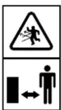

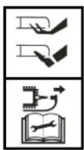
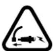
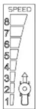
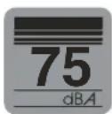




- Read Owner's Manual
- Keep bystander away.
- Drive Clutch
- Caution rotating blade—keep hands and feet clear.
- Remove Spark Plug.
- Variable Speed Drive Control
-
Noise Limit
-
Wear ear protection
- Wear eye protection
- Wear protective gloves
- Keep bystanders away
THIS MANUAL COVERS A RANGE OF DIFFERENT MASPORT MOWERS. SOME FEATURES MENTIONED MAY NOT APPLY TO YOUR MOWER.
IMPORTANT: Keep these instructions and the engine booklet in a safe place for future reference. They contain important information about your mower.
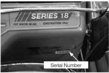
Record the serial number, you may need this when ordering ordering spare parts.
text_image
SERIES 18 CAT WIDTH: 46 cm | CONSTRUCTION MAY 75 Serial Number
CAUTION
A CAUTION INDICATES SPECIAL PRECAUTIONS THAT MUST BE TAKEN TO AVOID DAMAGE TO THE MOWER.

WARNING
A WARNING INDICATES SPECIAL PROCEDURES THAT MUST BE FOLLOWED TO AVOID INJURY TO THE OPERATOR OR ANY BYSTANDER.
SAFETY INSTRUCTIONS


PLEASE READ ALL INSTRUCTIONS BEFORE ATTEMPTING TO USE YOUR MOWER.
TRAINING
- Read the operating and maintenance manuals carefully. Be thoroughly familiar with the controls and the proper use of the equipment. Know how to stop the mower and disengage the controls quickly in an emergency.
- Never allow children or people unfamiliar with these instructions to operate the mower.
- Keep the area of operation clear of all persons, particularly small children and pets.
- Never mow while people, especially children, or pets are nearby;
- Keep in mind that the operator or user is responsible for accidents or hazards occurring to other people or property.
PREPARATION
- Thoroughly inspect the area where the equipment is to be used and remove all stones, sticks, wires, bones and other foreign objects before mowing, they could be thrown by the
blade.
- Do not operate the equipment when barefoot or wearing open sandals. Always wear substantial footwear and long trousers. It is advisable to wear suitable eye protection.
- Check the fuel before starting the engine. Do not smoke while fuelling the engine. Do not fill the fuel tank indoors, never remove the fuel cap off the fuel tank or add fuel when the engine is running or until it has been allowed to cool for several minutes after running. Clean off any spilled fuel before starting the engine.
- Never attempt to make a wheel height adjustment while the engine is running.
- Mow only in daylight, and always keep children away from the mowing area.
- Never operate the equipment in wet grass. Always be sure of your footing; keep a firm hold on the handle and walk; never run. Never walk backwards while cutting grass.
- Replace faulty silencers
- Before using, always visually inspect to see that the blades, blade bolts, and cutter assembly are not worn or damaged. Replace worn or damaged blades and bolts in sets to preserve balance.
OPERATION
- Disengage all blade and drive controls before starting the engine.
- Do not tilt the mower when starting the engine.
- Start the engine carefully with feet well away from the blades.
- Do not put hands or feet near or under rotating parts. Always keep clear of the blade and discharge opening.
- Do not change the engine governor settings or over-speed the engine. Excessive speed is dangerous and shortens mower life.
6 Stop the engine when crossing gravel drives, walks or roads. - Don't mow over heavy or solid objects as striking them with the blade can cause serious damage to the engine and will void your warranty.
- After striking a foreign object, stop the engine remove the wire from the spark plug, thoroughly inspect the mower for any damage, and repair the damage before restarting and operating the mower.
- If the mower should start to vibrate abnormally, stop the engine, disconnect the spark plug wire, and check immediately for the cause. Vibration is generally a warning of trouble.
- Stop the engine whenever you leave the mower, even for a moment, before cleaning the mower housing, and when making any repairs or inspections.
- When cleaning, repairing or inspecting, make certain the blade and all moving parts have stopped and that the engine has had time to cool. Disconnect the spark plug wire, and keep the wire away from the plug to prevent accidental starting.
- Do not run the engine indoors. Lethal exhaust gases can be produced.
- Shut the engine off and wait until the blade comes to a complete stop before removing the grass catcher or unclogging the chute.
- Mow across the face of slopes; never up and down. Exercise extreme caution when changing direction on slopes. Do not mow excessively steep slopes.
- Never operate the mower without proper guards, deflectors provided by the manufacturer, or other safety devices in place.
- Never pick up or carry a mower when it is operating.
- Where a fuel tap is fitted, turn it off at the conclusion of mowing and reduce the throttle
setting during runout.
- Do not operate the engine in a confined space where dangerous carbon monoxide fumes can collect.
- Walk, never run
- Use extreme caution when reversing or pulling the mower toward you.
- Stop the baldes if the lawmower has to be tilted for transportation when crossing surfaces other than grass, and when transporting the lawnmower to and from the area to be mowed.
- Do not start the engine when standing in front of the discharge chute.
MAINTENANCE
- Before using, check the blade(s) and blade bolt(s) for wear and damage. Replace worn or damaged blades and bolts in sets to preserve the balance. DAMAGED BLADES AND WORN BOLTS ARE MAJOR HAZARDS.
- Keep all nuts, bolts and screws tight to be sure the mower is in safe working condition.
- Never store the mower with fuel in the tank inside a building where fumes may reach an open flame or spark. Allow the engine to cool before storing in any enclosure.
- Store fuel in an approved container safely out of the reach of children in a cool, well ventilated place.
- To reduce fire hazard, keep the engine free of grass, leaves, or excessive grease.
- Check the catcher bag frequently for deterioration and wear, and replace worn bags. Check that replacement bags comply with the original manufacturer's recommendations or specifications.
STORING THE MOWER
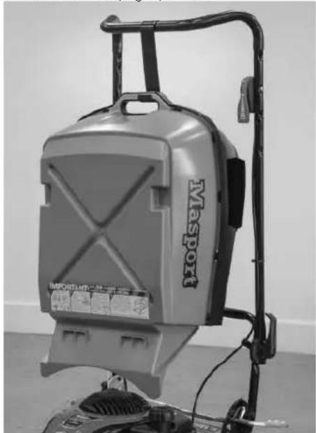
The handle can be folded to minimise space requirements.
FOLDING THE HANDLE
Loosen the clamp knobs or unlock the handle lever(s) in the middle of the handle and fold the top section over the engine.
Ergoshift models can also be stored by moving the handle to the upright position.
natural_image
Exterior view of a Maspond pressure cooker with attached wiring and control panel (no visible text or symbols)
CAUTION
Check that the control cables are not being strained while folding and unfolding the handle. Permanent kinks will make the controls difficult to operate.
TIPPING THE MOWER SAFELY FOR STORAGE OR INSPECTION.

CAUTION
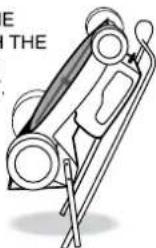
Tilting the mower—Drain fuel, then tilt the mower with the spark plug uppermost. Remove the spark plug lead.
ONLY TILT THE MOWER WITH THE SPARK PLUG UPPER MOST.
ASSEMBLING THE MOWER
Please refer to the following sections when preparing the mower for its first use.
- Fitting the handle
• Preparing the Engine
• Assembling the catcher
NOTE - The left and right sides of the mower are referred to as viewed from the operating position behind the handle.
FITTING THE HANDLE
In some cases the handle may be completely detached from the mower body although the upper handle may be connected by the throttle control cable. Carefully remove the mower and handles from the box together to avoid damaging the throttle control.
ASSEMBLING THE 'SCREW LOCK' HANDLE.
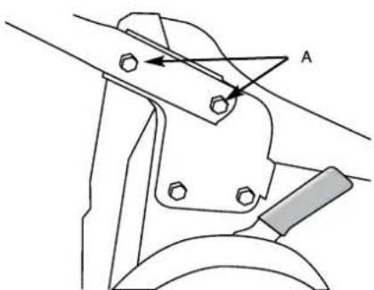
The lower handle is fitted to the mower using the four bolts located in the handle brackets, two on each side, 'A' in the drawing below. To bolt the lower handle to the mower fit the bolts through the lower handle then fit the handle to the mower body and tighten the nuts on the outside of the mounting brackets using a 13mm A/F socket or spanner.
natural_image
Technical line drawing of a mechanical clamp or bracket assembly (no text or symbols)Now attach the upper handle to the lower handle.
420MM MODELS
The 420mm model is shipped with the handle completely detached from the mower body although the upper handle may be connected by the throttle control cable to the engine. Carefully remove the mower and handles from the box together to avoid damaging the throttle control and cable.
ASSEMBLING THE LOWER HANDLE
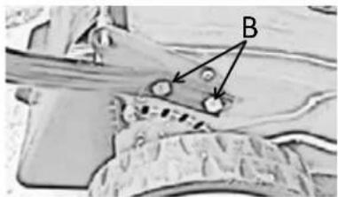
The lower handle stubs are fitted to the mower using the four bolts located in the handle brackets, two on each side, 'B' in the drawing below. To bolt the lower handle to the mower fit the bolts through the lower handle then fit the handle to the mower body and tighten the nuts on the inside of the housing using a 13mm A/F socket or spanner.
natural_image
Microscopic view of a biological or material structure with labeled points A and B (no readable text or symbols)Now attach the upper handle to the lower handle stubs.

CAUTION
Take care not to rotate the handle before fitting it, as this will tangle the control cable(s).
Fit the two long bolts through the holes in the lower handle from the inside with the round heads snug against the tube. Fit the holes in the upper handle over the two long bolts. Make sure that the throttle control is located on the right hand side. Attach the plastic knob to the outside of the lower handle bolt as shown below and tighten by hand until the upper handle is locked in position.
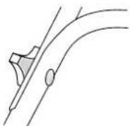
ASSEMBLING THE 'CAM LOCK' HANDLE.
Most of these models are fully assembled when packed, so all that is needed is to remove them from the carton, swing the handle to the operating position and lock the handle lever(s).
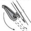
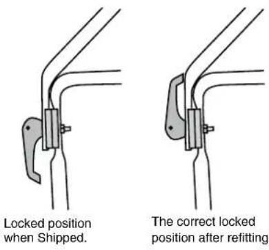
THE CAMLOCK HANDLES ON SOME MOWERS ARE REVERSED FOR SHIPPING. To turn them around unwind the nut to the end of the thread with a 13mmA/F spanner/socket, pull the camlock handle outwards and rotate it 180°. Retighten the nut until the handle locks firmly in place and it does not change position when in use.
FITTING THE THROTTLE CONTROL
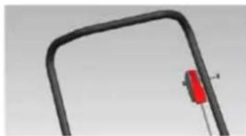
In some cases the throttle control may be completely detached from the upper handle.
Using the bolt and nut attached to the throttle control, attach the throttle on LH side of the upper handle (inside the handle).
natural_image
Close-up of a black metal saw with a red component inserted, no visible text or symbolsTHE 'ERGO' HANDLE
text_image
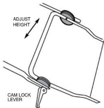
ADJUST HEIGHT CAM LOCK LEVERThe 'Ergo' handle can be adjusted to your preferred height. Simply release both cam lock levers, move the upper handle to the height required and re-clamp the cam locks. Where the mower has screw type locks, wind the knobs firmly clockwise to lock the handle.
ERGO SHIFT
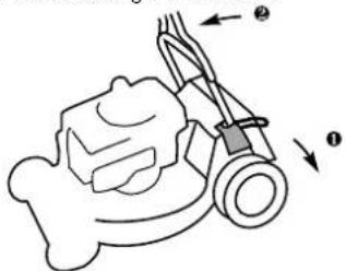
Some handles can be rotated forward to give easy access to the rear flap. Depress the foot lever u and push the handle until you feel resistance—in a near vertical position v. The handle can be moved back to the mowing position without using the foot lever.
text_image
Diagram of a lawn mower with labeled parts and directional arrows indicating motion or forceCONTRACTOR COMMERCIAL MODELS
ADJUSTING THE HANDLE HEIGHT
text_image
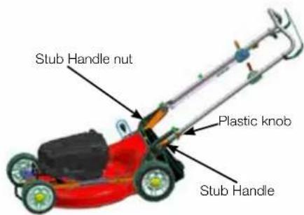
Stub Handle nut Plastic knob Stub HandleTo adjust the handle to suit your height on the 3 position handle setting, loosen and remove the inner stub handle nuts. Loosen the plastic knobs enough to pull out and swivel the stub handles to the required hole setting. Tighten the plastic knobs then refit and tighten the nuts.
PREPARING THE ENGINE

PLEASE READ AND UNDERSTAND THE ENGINE MANUFACTURERS ENGINE OWNERS MANUAL PRIOR TO OPERATING THE LAWNMOWER.

CAUTION
DO NOT START your four stroke engine before making sure that it has been filled with the right amount of the correct grade of oil. See engine instruction book for details.
TWO STROKE ENGINES
require no special attention to lubrication provided that the fuel/oil mixture is correct at all times.
FOUR STROKE ENGINES
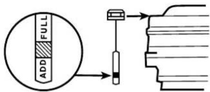
Four stroke (cycle) engines are shipped without oil. Place the mower on a level position, unscrew the 'OIL FILL' cap and slowly pour oil into the sump. Fill to the full mark on the dipstick. Use SAE 30 engine oil. When checking the oil level, and before running the engine, screw the dipstick firmly in place.
text_image
FULL ADDChecking the oil level if the engine is not fitted with a dip stick.
FUEL


WARNING
PETROL VAPOUR IS HIGHLY FLAMMABLE AND EXPLOSIVE. HANDLE WITH EXTREME CARE. STORE IN AN APPROVED CONTAINER. DO NOT FILL TANK WHEN ENGINE IS RUNNING OR IS STILL HOT. DO NOT ALLOW OPEN FLAME, MATCHES OR SMOKING NEARBY. FILL TANK OUTDOORS IN A WELL VENTILATED AREA. WIPE AWAY ANY SPILLS AND MOVE THE MOWER AWAY FROM ANY PETROL FUMES BEFORE STARTING ENGINE.

CAUTION
If a blue plug is fitted beneath the petrol filler cap it must be discarded. It is for transportation purposes only.
- For two stroke engines fuel ratio, refer to engine instruction book.
When filling the fuel tank, always leave an air space of about 5mm to allow for expansion of the fuel.

CAUTION
USE ONLY CLEAN FRESH PETROL AT ALL TIMES, preferably un-leaded, with an octane rating of at least 91. Four stroke (cycle) engines use straight fuel. Two stroke engines MUST have a fuel and oil mixture. See engine instruction book for details. Always mix two-stroke fuel thoroughly by shaking the oil and petrol together in a clean container before pouring into the engine tank. USE ONLY TWO STROKE (CYCLE) OILS when mixing two stroke fuel. We do not recommend the use of multi-viscosity oils or pre-mixed fuels.
ENGINE
Regular attention to a few simple items will ensure long and trouble-free service from your mower. Carry out the regular maintenance described in the engine manual, and check the engine mounting bolts regularly to be sure they are tight.
NOTE: THE ENGINE IS WARRANTED BY THE ENGINE MANUFACTURER AND NOT MASPORT. YOUR SPECIALIST MASPORT SERVICE DEALER CAN ASSIST WITH ENGINE RELATED WARRANTY MATTERS.

WARNING
Before making any adjustments to your mower make sure that the engine is turned off and that the blade has STOPPED ROTATING. Always disconnect the spark plug wire and make sure it cannot accidentally contact the spark plug before touching anything under the mower housing.
RUNNING THE ENGINE
ENGINE CONTROL
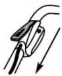
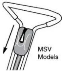
This is mounted at the top of the handle. It operates the choke, if fitted (for cold starting) and allows you to set the governed speed of the
engine.
text_image
MSV ModelsOn all models push control forward for full throttle.
You will not need to change the control setting constantly while mowing because the governor holds the selected speed, even under varying cutting loads. The positions for CHOKE (cold start), FAST, SLOW and STOP are usually marked. If STOP is not marked, move the lever beyond SLOW to stop the engine.
Some controls have symbols instead of words. On these,
means CHOKE,
means FAST,
means SLOW
means STOP.
If your engine control does not have the word CHOKE or the choke symbol I du have a Pulsa Prime engine. (See RUNNING THE ENGINE, MANUAL START MODELS
ENGINE CONTROL.
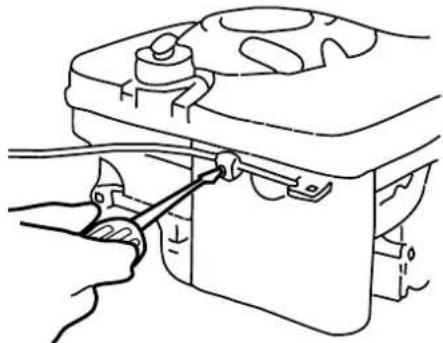
This MUST be correctly adjusted for easy starting and safe stopping. If you have cold starting problems, adjust the outer sleeve of the control cable under the clamp on the engine at the lower end of the cable. See engine instruction booklet for details. Make any adjustments only with the handle in its normal operating position. After adjusting, check that the choke butterfly fully closes at one end of the control lever travel, and that the ignition stop switch is activated at the other.
natural_image
Line drawing of a hand using a tool to adjust or install a mechanical component (no text or symbols present)STARTING
Ensure that the engine has been prepared correctly (see above) and that the fuel tap (if fitted) is turned ON. We recommend that you check the oil level before every mowing session.

WARNING
NEVER RUN THE ENGINE INDOORS OR IN POORLY VENTILATED AREAS. ENGINE EXHAUST CONTAINS CARBON MONOXIDE, AN ODOURLESS AND DEADLY GAS. KEEP HANDS, FEET, HAIR AND LOOSE CLOTHING AWAY FROM MOVING PARTS.
MANUAL START MODELS.
If the engine has not been running recently, set the engine control to the CHOKE position. For
Pulsa Prime engines (which have no CHOKE marking or symbol on the control), push the primer bulb on the side of the engine by the carburettor, refer engine owner's manual. (Do this also if you have just refilled the tank after running out of fuel). Grasp the starter grip, pull slowly until a resistance is felt and then pull forcefully to prevent kick-back. Repeat until the engine starts. Do not pull the cord with a jerk or release it until fully rewound. —When the engine starts and has warmed up for a short time, move the control to the desired speed. Should the engine not start due to 'flooding', move the control to SLOW and pull the starter six times to clear the flooding.
ELECTRIC START MODELS.

Please refer to the Electric Start instructions supplied with your mower.

WARNING
OPERATING THE STARTER ROTATES THE CUTTING BLADES - KEEP HANDS AND FEET WELL CLEAR.
HINTS FOR EASY STARTING
- Stand the mower on a paved drive or path where the blade is clear of the grass. If you must start on the lawn, move to an already cut area and/or raise the cutting height. Do not start the mower on a gravel surface.
- Start a warm engine with the control in the SLOW position.
- Keep the mower clean underneath.
HARD STARTING CHECK LIST Look for these faults:-
FUEL 1. Insufficient fuel in tank.
- Fuel tap shut off.
- Stale fuel.
- Water or dirt in fuel.
- Blocked air vent in fuel tank cap.
IGNITION 1. Loose spark plug wire.
- Dirty spark plug electrodes.
- Incorrect spark plug gap.
- Incorrect spark plug type.
OTHER 1. Choked air filter (Dirt or oil).
- Engine control cable mis-adjusted.
- Cutting blade obstructed.
STOPPING
Move the engine control to stop
DRIVE CONTROLS
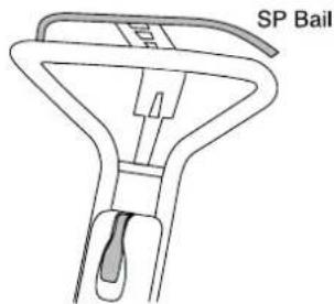
To engage the mower drive, simply push forward on the SP bail arm until it meets the handle grip. Releasing the pressure on the bail will de-clutch the drive mechanism. Naturally you may use the mower as a push model by gripping the handle in the normal way.
text_image
SP BailSP DRIVE CLUTCH CABLE ADJUSTMENT
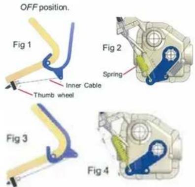
- Confirm that the cable inner wire will move at least 26 mm when the SP bail is moved from the clutch disengaged (open- Fig1 and 2) position to the engaged (closed-Fig3) position against the handle. The first 13mm moves the lever of the gearbox(Fig4) to the engaged position and the final 13mm gives the spring the desired 140N for the required tension on the gearbox cones to work properly without slipping under load. Adjust the contour of the bail slightly if necessary to achieve this wire stroke.
text_image
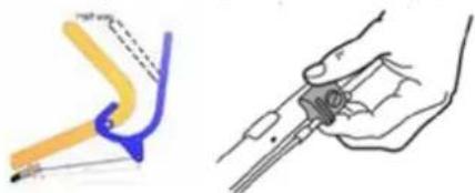
OFF position. Fig 1 Inner Cable Thumb wheel Fig 2 Spring Fig 3 Fig 4- Wheel the mower backwards toward you while gradually closing the SP bail, and note the position of the bail when extra resistance to backward movement indicates that the drive clutch is just engaging. This extra resistance should occur when the SP bail is half way between open and closed (Fig 5).
natural_image
Illustration of a hand holding a pen and a tool, with no visible text or symbolsFig 5
- If the engagement point is incorrect, adjust it by rotating the thumb-wheel on the anchor block at the top of the cable outer sleeve. Rotating the wheel clockwise will move the clutch engagement point nearer to the bail closed position, and anti-clockwise will move it toward the bail open position (Fig 6).
- Confirm that the adjustment is correct by re-testing the engagement point.
- Repeat this adjustment after 150 hours use of the mower or at any time if the mower drive seems to be slipping.
IMPORTANT: An incorrectly adjusted clutch cable, or using the mower with the SP bail not fully against the handle will cause clutch slippage, gearbox overheating and serious gearbox damage.

CAUTION
Adjust only to provide positive drive. Excess pressure will cause cable and belt stretch.
VARIABLE SPEED MODELS
Some models have an extra control mounted at the side of the handle to allow the travel speed of the mower to be varied without changing the engine speed. This control moves into an one of eight positions. Move the lever forward to increase travel speed and backward to lower it.
THIS LEVER SHOULD BE MOVED ONLY WHILE THE ENGINE IS RUNNING.
[If it is inadvertently moved back when the engine is stationary the drive belt will slacken and slip. To regain traction, move the lever forward with the drive disengaged and the engine running.]
Speed changes can be made whether the mower is moving or not.
CONTRACTOR COMMERCIAL MODELS
Self-propelled 3 Speed models.
The three speed gearbox can be changed to 1st 2nd or 3rd while the engine is running or not with three distinct positions in the gearbox.
BLADE CONTROL LEVER FOR BBC MODELS
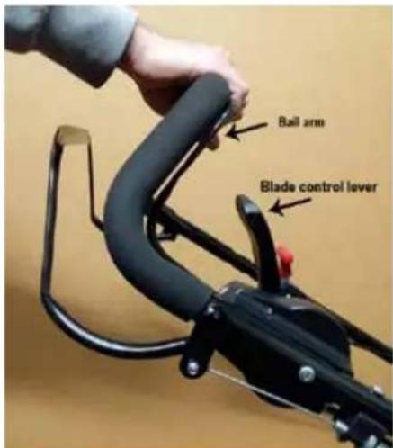
To start the blade rotation, hold the inner bail arm against the handle with your left hand. With the engine running at full speed, push the control lever quickly all the way forward and then return it back to the start position. Keep holding the bail arm against the handle. To stop the blade rotation, simply release the bail arm. The blade will stop quickly and the engine will continue to run.
text_image
Rail arm Blade control lever
CAUTION
The blade has been designed to stop and start while the engine is running.
NEVER PUT YOUR HANDS OR FEET NEAR THE BLADES WHILE THE ENGINE IS RUNNING EVEN IF THE BLADES HAVE STOPPED
THE GRASS CATCHER
text_image
Open Clip & Slip Over Rear Cross Member Top panel Clip Cross Member Side Clip Frame Screw Front Clip Front Lip Frame Screw Nut Bottom panel Lip Nut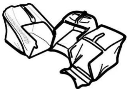
natural_image
Line drawing of two folded paper pieces (no text or symbols)CATCHER ASSEMBLY
There are three catcher types:
A. Bag Catcher
B. Moulded Plastic Catcher
C. Aero Catcher (moulded plastic top sections with fabric side panels.)
A. BAG CATCHER
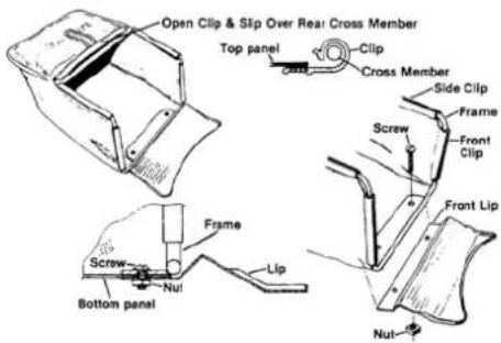
- Slide the bag over the wire frame. Fit the plastic clip up under the frame crossmember (the one which is formed into a handle) and hook the clip onto the wire crossmember. You may need a lever such as a screwdriver to open one end of the clip to get it started over the wire. Pass the side and front clips inside the frame and hook them onto the wire in a similar way.
- Fasten the metal front lip to the catcher assembly by bolting it to the plate on the bottom of the frame. The bottom panel of the catcher should be fitted between the plate and the lip as shown. Fit the screws from the top with the nuts under the lip, and tighten them securely.
B. MOULDED PLASTIC CATCHER
There are two types. One has the top cover and handle already fitted to the top shell of the catcher, while the other requires these parts to be assembled.
IF YOUR CATCHER HAS THESE PARTS
ALREADY ASSEMBLED, START AT STEP 4.
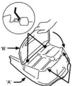
- Place the top of the catcher shell (A) on a firm level surface with its mesh upwards.
- Holding the top cover (B) with its concave side facing the mesh, lift its rear end and engage the front clips with the hooks on the catcher top shell. Keeping them engaged, swing the rear of the cover downwards and press it down until the barbs on the cover engage with the slots in the shell.
text_image
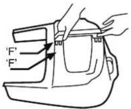
Diagram illustrating hand positioning and movement of a vehicle's seat, labeled with points A', B', and directional arrows.- Look for the "F" on the handle and ensure that it will be adjacent to the "F" on the catcher shell. Fit the handle by pressing it firmly into the square recesses in the catcher top.
text_image
'F' F'Turn the assembly over to confirm that the barbs on the handle are fully home, and push the tabs on the shell back into position to retain the handle.
- Place the top shell on a solid work bench, open side up. Don't use a table which may be damaged by scratching.
- Position the bottom shell, upside down,
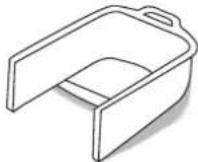
over the top shell, carefully aligning the two parts and ensuring the barbed clips are aligned with their corresponding slots and squeeze the rear handles together.
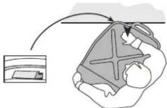
- Keeping the catcher upside down, move the assembly so the lip and rear handle is supported by the edge of the bench (see diagram) and catcher is trapped between your body and the bench.
natural_image
Illustration of a person lying on the ground with an arrow indicating motion, no text or symbols present- Strike the top of the assembly with an open hand above the part supported by the bench. You should hear the barb click into place in its slot - if not, check the alignment and strike again with a little more force.
natural_image
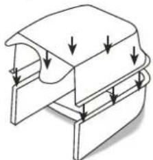
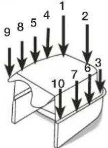
Pure technical line drawing of a mechanical component with no text, numbers, or symbols- Working from left to right, and starting by the rear handle, move around the catcher, supporting each fastener in turn on the
edge of the bench, as it is pushed into engagement.
text_image
1 2 3 4 5 6 7 8 9 10- Finally inspect carefully to ensure that all clips are fully engaged.
C. AERO CATCHER
The bag and moulded plastic catchers have lips at the front which fit the top of the crossbar on the base of the discharge tunnel, while the Series 18 Rotarola catcher has two lugs that fit into the hooks of the handle brackets.
Aero catchers have two plates under the front crossbar which hook into the support channel at the rear of the mower near the ground. Keep the rear of the Aero catcher near the ground until the plates are engages with teh support channel, then pivot the catcher up into position. The chute or flap can be release as it swings up since the hooks on the front of the catcher will automatically engage on the mower, allowing the chute or flap to drop into the lockedposition on the catcher.
For all types of catcher, make sure that rear edge of the chute of flap is fully engaged with the catcher to hold it in place securely.
FITTING THE CATCHER

WARNING
THE CATCHER SHOULD BE FITTED TO AND REMOVED FROM THE MOWER ONLY WHEN THE ENGINE HAS STOPPED.
Standing to the right of the mower, reach down with your right hand and pull back and up on the handle of the safety flap or Smart Chute and lift it until it is parallel with the handle. Pick up the catcher with your left hand and swing it into position at the rear of the mower. The catcher lip of the fabric and plastic catchers fits on top of the crossbar or the base of the tunnel, while the two hooks at the top of the Aero catcher mouth sit on top of the brackets inside the discharge outlet of the mower. The Series 18 Rotarola catcher has two lugs which fit on the hooks near the handle brackets of the mower. Once the catcher is positioned correctly, lower the flap or Smart Chute to hold it in place. Make sure that the rear edge of the flap or Smart Chute is fully engaged on the lip or bar at the rear of the catcher mouth.
420MM MODELS
FITTING THE PLASTIC CATCHER
Standing to the right of the mower, reach down with your right hand and pull back and up on the handle of the rear flap and lift it until it is parallel with the handle. Pick up the catcher with your left hand and swing it into position at the rear of the mower.
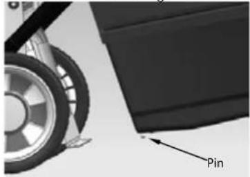
The catcher lip has two pins that need to be lined up with the slots of the housing.
natural_image
Close-up of a mechanical component with a labeled 'Pin' arrow pointing to a specific part (no other text or symbols visible)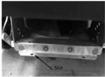
text_image
Slot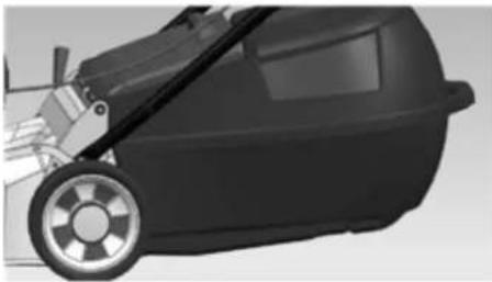
natural_image
Side view of a black and silver robotic lawn mower (no text or symbols visible)Once the catcher is positioned correctly, lower the flap to hold it in place. Make sure that the rear edge of the flap is fully engaged on the lip at the rear of catcher mouth.
FITTING THE FABRIC CATCHER
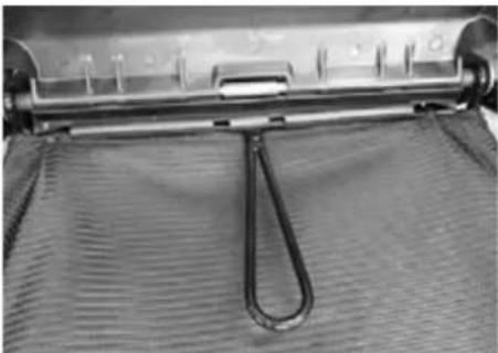
Standing to the right of the mower, reach down with your right hand and pull back and up on the handle of the rear flap and lift it until it is parallel with the handle. Pick up the catcher with your left hand and swing it into position at the rear of the mower.
The fabric catcher has two lugs which fit on the hooks near the handle brackets of the mower.
natural_image
Close-up of a metal tool resting on a textured fabric surface (no visible text or symbols)Once the catcher is positioned correctly, lower the flap.
REMOVING THE GRASS CATCHER
natural_image
Line drawing of a person using a tool to cut a piece of material, no text or symbols present
WARNING
ALWAYS WAIT UNTIL THE ENGINE AND BLADE HAVE STOPPED COMPLETELY BEFORE REMOVING THE CATCHER OR ADJUSTING THE MOWER. REMEMBER, THE MUFFLER AND NEARBY AREAS MAY BE VERY HOT.
ALL MODELS
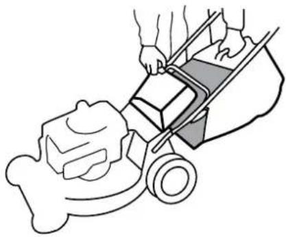
Stop the engine and stand to the right of the mower. Grasp the catcher handle with the left hand and lift slightly while raising the safety flap or smart chute with the right hand. Lift the catcher clear and lower the flap or Smart Chute to cover the grass discharge outlet.

WARNING
Before clearing away any grass which may have lodged in the grass chute, ALWAYS STOP THE ENGINE, make sure the blade has stopped rotating, AND REMOVE THE SPARK PLUG WIRE.
EMPTYING
Dump the grass from the catcher by holding it vertical, using the rear handle of the moulded catcher or holding the rear end of the steel frame of the fabric catcher. Shake if necessary to dislodge a full load.
CATCHER LEVEL INDICATOR
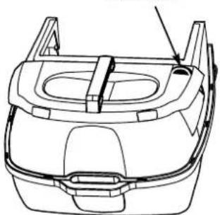
Some grass catcher models have a Catcher Level Indicator to show how much grass has been collected. The indicator functions only when the engine is running at grass cutting speed. When the catcher is empty, the indicator will show all green, nut as the grass progressively builds in height, a red indicator zone will appear and increase in size. Attempting to over-fill the catcher will result in discharge chute blockage or a "dribble" of grass from the front of the catcher.
Experience in your particular grass and cutting conditions will soon show the size of the red indicator area corresponding to the ideal catcher emptying point, Hose the catcher thoroughly after each use to keep the indicator movement free.
Level Indicator
natural_image
Technical line drawing of a car front bumper with mounting brackets and a handle (no text or symbols)GRASS CATCHER MAINTENANCE
FABRIC TYPES.
These depend on a free flow of air thought the fabric for effective grass collection. Wash as needed to restore and open mesh in the fabric. Do not leave a fabric bag in direct sunlight when not in use. While the bag will not rot if stored wet, prolonged sunlight exposure can cause premature breakdown of the material. Do not leave clippings in the catcher for extended periods.

WARNING
CHECK THE CATCHER BAG FREQUENTLY FOR DETERIORATION AND WEAR, AND REPLACE IF WORN. Use only genuine original equipment replacement catcher bags as others could be dangerous.
MOULDED PLASTIC TYPE.
These also need a free passage of air for efficient catching. Keep the air outlet mesh clear by hosing it frequently. Do not leave clippings in the catcher.
CUT HEIGHT CONTROL
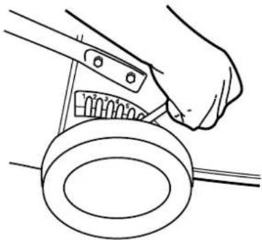
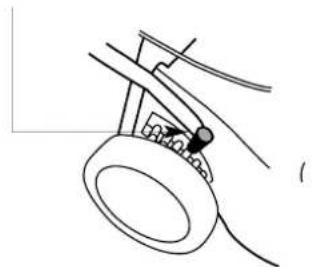
The single point cut height control adjusts all four wheels simultaneously. To operate, steady the mower by grasping the handle with one hand, pull the lever outwards from the mower with the other hand, and move it to the desired setting.
natural_image
Line drawing of a hand using a tool to adjust or install a mechanical component (no text or symbols present)MOWING ACCESSORIES
A grass deflector chute for mowing without a catcher is available for some models from your dealer. Not required for 'Smart Chute' models.
MOWING ADVICE
The best time time to mow your lawn is the early afternoon. By this time the grass has had a chance to dry out. Also the sensitive newly cut grass area isn't exposed to the direct sun.
For healthy growth, grass should not be cut too short. Using the lowest settings can result in destruction of the crown of grass, allowing flat lying weeds to develop.
Vary your cutting pattern from week to week. One week mow your lawn from north to south, the next week, mow your lawn from east to west. This will help prevent matting and graining of the grass.
For best performance, always keep the mowers blade sharp. A dull blade tends to tear, not cut, the blades of grass. When cutting very long grass, a preliminary cut on a high setting,
followed by a lower cut (preferably a day or so later), will minimise the overall time required for the job.
Do not try to cut too much off the grass at one time. This can cause excessive loads to be put on the engine and also effect the mulching performance.
Avoid using the lowest two or three height settings when mulching. For best results when mulching; cut off only the top third (or less) of the grass. Cutting lower than this will have a detrimental effect on the mulching performance.
AVOID USING THE LOWEST TWO OR THREE CUT SETTINGS IN WET OR VERY LONG GRASS.
natural_image
Line drawing of a hand holding a circular object with a small object inserted, no text or symbols presentAs you turn the mower at the end of a strip you may notice unmulched grass. The mower deck is naturally tilted upward when turning so that the air flow which holds the grass in position for recutting is momentarily decreased. After mowing the lawn, you can go back and mow only the turns so that the clippings are no longer visible.
Clean the mowing chamber frequently to remove grass build-up. This will keep mowing performance at its best, especially when mulching. Avoid cutting your lawn when it is wet. Wet grass tends to form clumps and interferes with the mulching action of the mower.
If you are not collecting the cut grass, mow in a pattern that deposits the clippings on the previously cut swathe. So, if your mower discharges clippings on the left, the next cut should be to the right of the previous one, and vice-versa.
If you use the mower often without collecting the clippings, you will find that the accessory grass delivery chute (available from your Dealer for most models) will assist by spreading the clippings more effectively.

WARNING
DISCHARGE OPENINGS MUST BE GUARDED AT ALL TIMES. DO NOT REMOVE THE GRASS DEFLECTOR OR HOLD THE SAFETY FLAP UP WHILE MOWING.
When cutting close to obstructions such as tree trunks, and when mowing to the edge of a lawn where there is no wheel support, use the left side of the mower, giving a useful blade 'overhang' for ready access to awkward areas.
MOWING ADVICE—'SMART CHUTE'
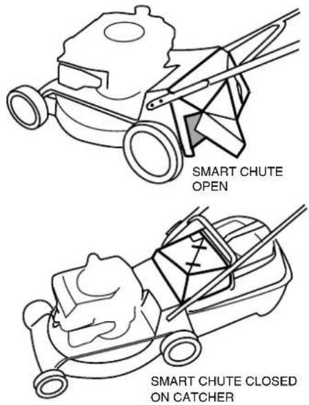
The 'Smart Chute' allows you to mow without
catching the grass or mulching. By simply opening the 'door' located on the bottom left hand corner of the 'Smart Chute', the lawn can safely be mown while smoothly spreading the clippings to the left. For wet, heavy or very long grass we advise not using the lowest two of three cutting heights as this may cause clogging. If is still persists, try walking slower, cutting a narrower strip or raising the cut height more.
text_image
SMART CHUTE OPEN SMART CHUTE CLOSED ON CATCHER
WARNING
Never use the 'Smart Chute' on the catcher with its door open. This could cause damage or injury to property or bystanders.
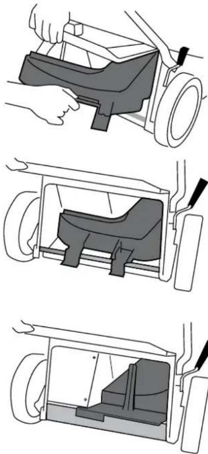
FITTING THE MULCHING BLOCK TO THE MOWER
- Stop the engine
- Make sure the discharge chute and the underside of the mower are clean. See AFTER MOWING.
- Raise the flap, and using the hand hold on the mulching block, insert the mulching block, the angled section to the mowers right, into the discharge chute.
In the case of "open-back" mowers, make sure that the back of the block is sitting on the rear axle before lowering the flap. When fitting the block into a mower with a grass discharge chute, ensure that the lug at the left side of its base is slipped into the notch at the bottom rear of the chute sidewall before lowering the flap. See 'Mowing Advice' for mulching tips.
natural_image
Three technical diagrams showing a car interior with hand positioning, internal components, and exterior view (no text or symbols)420MM MODELS
Raise the flap, and using the hand hold on the mulching block, insert the mulching block, the angled section to the mowers right, into the discharge chute.
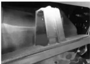
natural_image
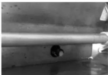
Close-up of a mechanical component with translucent body and textured surface (no visible text or symbols)When fitting the block into a mower, ensure that the pin at the left side of its base is into the notch of the housing before lowering the flap.
natural_image
Close-up of a metallic cylindrical object with a hole, possibly a mechanical part or fixture (no visible text or symbols)FITTING THE SIDE DISCHARGE CHUTE
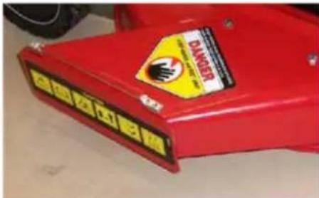
For mowers equipped with a side discharge, the discharge openings must be guarded at all times.
THE MOWER MUST NEVER BE OPERATED WITHOUT EITHER THE GRASS CHUTE OR THE CHUTE FLAP INSTALLED.
text_image
DANGER ELECTRIC BURG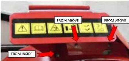
text_image
FROM ABOVE FROM ABOVE FROM INSIDEGRASS CHUTE TO BE ATTACHED AS SHOWN. 2 x screws from above with nuts underneath and 1 x screw from inside the housing with nut inside grass chute.
DO NOT REMOVE THE GRASS CHUTE OR HOLD THE CHUTE FLAP OPEN.
PERSONAL INJURY, INJURY TO BYSTANDERS OR DAMAGE TO PROPERTY COULD RESULT FROM OPERATING A MACHINE WITHOUT THESE ITEMS FITTED CORECTLY.
CHIPPER MOWERS

WARNING
Keep feet clear of the mower body when using the chipper tube.
When using the chipper tube place the mower on a level area where markings by he rotating chippings won't matter. Before starting the mower fit the catcher and set the cut height to its lowest settling. Check that the chipper feed tube is clear and the feed intake flap is in good order.

WARNING
Check frequently that the blade is sharp and the retaining screws are tight.
Branches up to 35mm can be chipped using the chipper tube. Only green timber should be chipped. DO NOT chip hard or dry wood. Hard and/or dry woods can be place unreasonable loading on the machine causing damage. Check that there are no nails or foreign objects in the material being chipped.

WARNING
Always stop the engine before attempting to clear any obstruction from under the mower or in the chipper tube.
Slowly feed material into the intake tube. Sturdy gloves, footwear, ear and eye protection should
be worn. Empty the catcher frequently to avoid building up chippings inside the mower housing. Clear debris away from around the engine frequently to prevent any restriction with cooling air flow and prevent the risk of fire. Stop the engine before removing the catcher.
AFTER MOWING
CLEANING

MODELS WITH A CYCLOWASH FITTING.
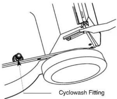
Stop the engine and remove the catcher. Attach a garden hose fitting to the cycowash fitting and start the engine. Allow a good flow of water to run for 2-3 minutes. Stop the engine and remove the hose. Hose the Catcher.
text_image
Cyclowash FittingMODELS WITHOUT A CYCLOWASH FITTING. Stop the engine and remove the catcher. Start the engine. Keeping well clear of mowing parts, apply a garden hose to the Wash port with a good flow of water for 2-3 minutes. Hose the catcher.
MODELS WITHOUT A CYCLOWASH PORT. Stop the engine, when the blade has stopped, disconnect the spark plug wire. Remove the catcher and tip the mower in accordance with the engine instruction book maintenance section (spark plug uppermost). Hose the underside of the mower clean. Hose the catcher.

CAUTION
DO NOT HOSE THE ENGINE, as water can damage the air cleaner and the ignition system. REFER TO ENGINE INSTRUCTION BOOK MAINTENANCE SECTION BEFORE TILTING MOWER. STORE YOUR MOWER ON ITS WHEELS, not its side.
BLADES
DAMAGED BLADES AND WORN BOLTS ARE MAJOR HAZARDS.
Check the blade mounting bolts at frequent intervals for proper tightness.
Check the blade condition frequently, particularly if the mower has hit a foreign object or is vibrating. Sub-standard cutting and catching will
result from a neglected blade. Your Authorised Dealer will be happy to sharpen or replace blades as necessary.

CAUTION
ALWAYS USE GENUINE ORIGINAL EQUIPMENT PARTS TO ENSURE SAFETY AND PROPER PERFORMANCE. Substitute parts can be disappointing and dangerous.
BLADE SERVICING INSTRUCTIONS
BAR AND DISC BLADES.
- Remove the spark plug lead and position it to prevent accidental contact with the spark plug.
- Tilt the mower upright - refer to maintenance section of the engine instruction book before tilting the mower.
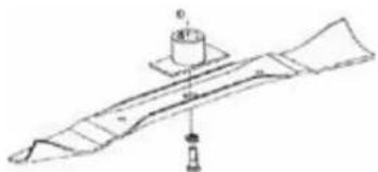
- BAR BLADES. Remove the central bolt and spring washer.
- Remove the blade. Either sharpen and balance the old blade, or fit a new one. Assemble in the reverse order.
natural_image
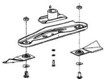
Technical line drawing of a mechanical component with no visible text or symbolsFollow steps 1 and 2 above. The cutting tips can be removed and replaced by removing the blade carrier from the mower. Note the component positions when dismantling. When refitting the blade carrier ensure the slots fit properly over the lugs and the drive plate, and replace the mounting bolts if they show signs of wear.
natural_image
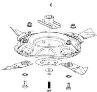
Exploded view diagram of a mechanical component with multiple parts and mounting holes (no text or labels)Quick Cut Blade
natural_image
Exploded view diagram of a mechanical assembly with no visible text or symbolsQUADCUT® BLADE
CHIPPER BLADE.
- Follow the servicing instructions for removing the "Bar and Disc Blades" on this page.
- When the blade carrier is removed from the crankshaft it can be place in a vice and the chipper blade removed.
- Either sharpen and balance out the old blade, or fit a new one. The mower blade should also be inspected at the same time.
- Assemble in the reverse order, taking care to align the keyway slot in the blade and the blade driver.

natural_image
Technical line drawing of a mechanical assembly with bolts and a flange (no text or symbols)BLADE REPLACEMENT TORQUE SETTINGS:
Blade center bolt 45-50 Nm (33-37 ft.lb)
Four 6mm chipper blade bolts 9-11 Nm (6.6-8 ft.lb)
Four 8mm chipper 20-22 Nm (15-16 ft.lb) blade bolts
Tip mounting bolt 20-25 Nm (15-18 ft.lb)
CONTRACTOR COMMERCIAL MODELS WHEEL TORQUE SETTING:
Four wheel M8 nyloc 8 - 9 Nm nuts (5.9 - 6.6 ft.lb)
ENGINE MAINTENANCE
Consult the engine booklet for the makers instructions.
DRAINING THE OIL.
While most engines have a drain plug underneath them, it will be found more convenient to remove the oil dipstick and tip the mower on its side. Collect the old oil in a suitable tray such as a two litre ice cream container.
IGNITION.
Your engine has a breaker-less solid state ignition system which requires no maintenance other than occasional attention to the spark plug. We recommend cleaning and re-gapping every 50 hours with replacement every 100 hours (see engine instruction booklet).

CAUTION
DO NOT SANDBLAST PLUGS as abrasive grains can enter the engine and cause serious damage. USE ONLY THE EXACT TYPE OF REPLACEMENT PLUG specified in the engine instruction booklet.
AIR CLEANER.
A clean filter cartridge, correctly fitted, is ESSENTIAL for long engine life. Service the filter every 25 hours running (more often under adverse conditions) according to the instructions in the engine booklet.
MUFFLER

A rusted or damaged muffler can permit increased exhaust noise. Check the muffler condition periodically and replace it only with a genuine original equipment part.
DRIVE MAINTENANCE
ROTAROLA.
Every 25 hours -
Remove the outer chain cover and apply grease to the chain.
Every 100 hours -
Remove the outer chain cover, disconnect the outer chain at its connecting link, withdraw the sprocket at the top end of the inner chain cover. Remove the inner chain cover and apply grease to the chain.
OTHER SELF PROPELLED MODELS.
Every 100 hours -
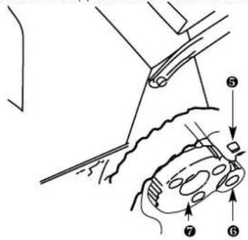
Remove each rear wheel by removing the hub cap, and undoing the 8mm nyloc nut and washer retaining the wheel to the axle. Remove the circlip retaining the pinion, taking care not to over stretch it, and remove the washer and pinion. Apply grease to pawl y, pinion bore z, and wheel gear {. Take care to replace the pawls exactly as they were removed, and do not move pinions to the opposite side of the mower.
text_image
Technical diagram showing a mechanical assembly with numbered components, likely illustrating a turning or disassembly process.GEARBOX.
The gearbox on these models is a sealed unit that requires no maintenance. Just keep the outside clean.
CLEANING MAINTENANCE
THE FOLLOWING MAINTENANCE IS REQUIRED EVERY 100 HOURS OR WEEKLY IF USED COMMERCIALLY (REFERS ONLY TO SELF-PROPELLED MOWERS)
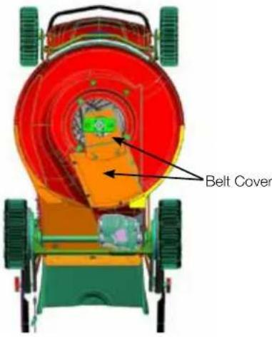
Remove both the gearbox and drive belt covers.
text_image
Belt Cover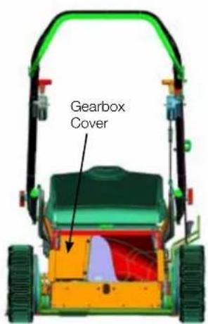
text_image
Gearbox CoverClean out any debris within the drive belt cavity and around the gearbox. Ensure that there is no grass build up between the gearbox clutch arm and travel stop.

WARNING!
Do not use a pressure washer around the gearbox.
- Check that the drive belt is tight and has the correct tension. Adjust if necessary.
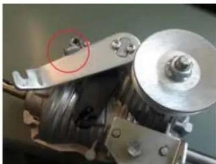
- Check that the clutch arm reaches the travel stop when the bail arm is released and adjust if necessary. There should be a small amount of inner wire slack in this position.
natural_image
Close-up of a mechanical assembly with a red-circled component and metallic components (no visible text or symbols)-
Replace the covers.
-
Remove both rear wheels and clean out any debris. Grease the teeth on the gears and reassemble.
IMPORTANT
Tighten the M8 nyloc nuts to 8 - 9 Nm.
BELT ADJUSTMENT
SINGLE SPEED MODELS.
(Except self propelled Chipper models & Rotarola)
Keeping the spark plug uppermost, tilt the mower to gain access to the gearbox. Using two 10mm AF spanners, slacken the screw which clamps the gearbox anchor bracket to the mower housing just enough to allow the gearbox to be rotated about its output shaft. Rotate the gearbox to take any slack out of the V belt drive and reclamp the anchor bracket in its new position by tightening the clamp and screw firmly.
SELF PROPELLED CHIPPER MODELS AND ROTAROLA
These have a belt tensioning idler pulley. To adjust this, slacken off the clamp screw or nut which holds the V shaped idler pulley post and slide the post along the slot in the body. Re-lighten the screw or nut when the slack in the belt has been eliminated.
VARIABLE SPEED MODELS.
DO NOT tip the mower up as described above for single speed models. Variable speed models have an adjuster on the cable running down from the speed control to the drive mechanism. Alter this adjuster only if the travel of the speed control lever does not match the full range of available travel speeds.
The adjuster has three parts, two end fittings each attached to upper and lower outer cables, and a central barrel connected to the end fittings by right and left hand threads. Keeping the end fittings stationary, rotate the barrel to push the ends apart to increase travel speed, and to bring the end fittings together to reduce travel speed. Using this adjuster will compensate for belt stretch or wear which may occur.
CONTRACTOR COMMERCIAL MODELS
BELT ADJUSTMENT
text_image
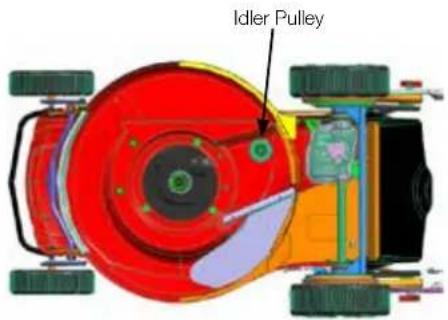
Idler PulleyIf the belt is to be replaced or worn and slipping and requires adjustment. Follow the servicing instructions for removing the "Bar and Disc blades" as explained in the Owner's manual. Remove the blade driver and belt covers.
Using two spanners loosen the nut and bolt holding the idler pulley, while pressing it to tension the belt tighten the nut and bolt.
TROUBLE SHOOTING
| TROUBLE PROBABLE CAUSE SOLUTION | ||
| Uneven or poor cut Blunt blade Sharpen blade | ||
| Heavy mulch left on cut strip Cutting height is too low for the height of the grass being cut. | Adjust the cutting height to approximately on third of the length of the grass. Then work down to the desired height. | |
| Engine not running at full speed Move the throttle to fast. | ||
| Underside of the mower's deck is clogged with wet grass clippings | Hose off the underside of the mower using they cyclowash hole in the mower body | |
Head Office - New Zealand
1-37 Mt Wellington Highway. Panmure,
PO Box 14 349
Auckland 1741
Head Office - Australia
1/40 Abbots Road
Dandenong South
Melbourne
Victoria 3175