
DinionXF-LTC 0620 - Security Camera BOSCH - Free user manual and instructions
Find the device manual for free DinionXF-LTC 0620 BOSCH in PDF.


| Product Type | Security Camera |
| Brand | Bosch |
| Model | DinionXF-LTC 0620 |
| Image Sensor | 1/3-inch CCD |
| Resolution | 540 TVL (analog) |
| Minimum Illumination | 0.05 lux (color), 0.01 lux (B/W) |
| Day/Night Function | Yes, mechanical IR cut filter |
| Lens Mount | CS-mount, varifocal lens included |
| Focal Length | 2.8–12 mm (varifocal) |
| Video Output | Composite 1 Vp-p, 75 Ohm (BNC) |
| Power Supply | 12 VDC or 24 VAC, 3.6 W max |
| Dimensions (W x H x D) | 65 x 52 x 120 mm (2.56 x 2.05 x 4.72 in) |
| Weight | Approx. 0.35 kg (0.77 lb) |
| Operating Temperature | -10°C to +50°C (14°F to 122°F) |
| Protection Class | IP30 (indoor use) |
| Main Functions | Day/night switching, motion detection, privacy masking, auto white balance |
| Maintenance | Clean lens with soft cloth; avoid solvents; check cables regularly |
| Security | Password protection for configuration via OSD menu |
| Spare Parts & Repairability | Contact Bosch service; lens and filter replaceable by qualified technician |
| General Information | Analog SD camera compatible with DVRs; manual includes OSD menu setup |
Frequently Asked Questions - DinionXF-LTC 0620 BOSCH
User questions about DinionXF-LTC 0620 BOSCH
0 question about this device. Answer the ones you know or ask your own.
Ask a new question about this device
Download the instructions for your Security Camera in PDF format for free! Find your manual DinionXF-LTC 0620 - BOSCH and take your electronic device back in hand. On this page are published all the documents necessary for the use of your device. DinionXF-LTC 0620 by BOSCH.
USER MANUAL DinionXF-LTC 0620 BOSCH
— LTC 0620 & LTC 0495 series Day/Night cameras
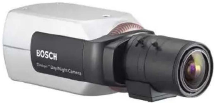
natural_image
Exterior view of a Bosch Binon™ Day/Night Camera (no visible text or symbols beyond branding)
Security Systems
Installation Instructions
15-bit digital day/night
cameraEN
Installationshandbuch
15-Bit digitale Tag-/Nacht-
Kamera
The lightning flash with arrowhead symbol, within an equilateral triangle, is intended to alert the user to the presence of uninsulated “dangerous voltage” within the product's enclosure that may be of sufficient magnitude to constitute a risk to persons.

Warning
The exclamation mark within an equilateral triangle is intended to alert the user to the presence of important operating and maintenance (servicing) instructions in the literature accompanying the appliance.

Caution
To reduce the risk of electric shock, do not remove cover (or back). No user-serviceable parts inside. Refer servicing to qualified service personnel.
Important Safeguards
- Read these instructions.
- Keep these instructions.
- Comply with all warnings.
- Follow all instructions.
- Do not use this equipment near water.
- Clean only with dry cloth.
- Do not block any ventilation openings. Install in accordance with the manufacturer's instructions.
-
Do not install near any heat sources such as radiators, heat registers, stoves, or other equipment (including amplifiers) that produce heat.
-
Do not defeat the safety purpose of the polarized or grounding-type plug. A polarized plug has two blades with one wider than the other. A grounding type plug has two blades and a third grounding prong. Both the wide blade and the third prong are provided for your safety. If the supplied plug does not fit into your outlet, consult an electrician for advice.
- Protect the power cord from being walked on or pinched particularly at plugs, convenience receptacles, and the point where they exit from the equipment.
- Only use attachments/accessories specified by the manufacturer.
- Unplug this equipment during lightning storms or when unused for long periods of time.
- Refer all servicing to qualified service personnel. Servicing is required when the equipment has been damaged in any way, such as when power supply cord or plug is damaged, liquid has been spilled or objects have fallen into the equipment, the equipment has been exposed to rain or moisture, does not operate normally, or has been dropped.
- An all-pole mains switch with a contact separation of at least 3mm in each pole shall be incorporated in the electrical installation of the building.

Warning
To reduce the risk of fire or electric shock, this apparatus should not be exposed to rain or moisture and objects filled with liquids, such as vases, should not be placed on this apparatus.
FCC Information
This equipment has been tested and found to comply with the limits for a Class B digital device, pursuant to part 15 of the FCC Rules. These limits are designed to provide reasonable protection against harmful interference in a residential installation. This equipment generates, uses and can radiate radio frequency energy and, if not installed and used in accordance with the instructions, may cause harmful interference to radio communications. However, there is no guarantee that interference will not occur in a particular installation. If this equipment does cause harmful interference to radio or television reception, which can be determined by turning the equipment off and on, the user is encouraged to try to correct the interference by one or more of the following measures:
- Reorient or relocate the receiving antenna.
- Increase the separation between the equipment and receiver.
- Connect the equipment into an outlet on a circuit different from that to which the receiver is connected.
- Consult the dealer or an experienced radio/ TV technician for help.
Note
Any change or modification of the equipment not expressly approved by Bosch could void the user's authority to operate the equipment. For additional information or to speak to a representative, please contact the Bosch Security Systems location nearest to you or visit our web site at www.boschsecuritysystems.com
Introduction
The Dinion ^XF Day/Night is a high-performance smart surveillance color camera. It incorporates 15-bit digital signal processing for outstanding picture performance under all lighting conditions. The Dinion ^XF Day/Night is easy to install and ready to use, and offers the best solution for demanding scene conditions. Features include:
• Day/Night camera with mechanically switching IR filter
- Three pre-programmed operation modes
- Noise elimination, true color reproduction
- Adaptive dynamic range optimization
- Bilinx™ bi-directional coaxial communications
- Genlock including sub-carrier locking
• Enhanced video motion detection
Type number overview
| Type number LTC | 0620/11 | LTC0620/21 | LTC0620/51 | LTC0620/61 |
| Standard PAL | NTSC PAL NTSC | |||
| Supply voltage | 24 VAC or 12 VDC | 230 VAC 50Hz | 110 VAC 60Hz | |
| CCD type 1/2" | ||||
| Type number LTC | 0495/11 | LTC0495/21 | LTC0495/51 | LTC0495/61 |
| Standard PAL | NTSC PAL NTSC | |||
| Supply voltage | 24 VAC or 12 VDC | 230 VAC 50Hz | 110 VAC 60Hz | |
| CCD type 1/3" | ||||

Caution
Ensure that your power supply matches the rated voltage of your camera before installing.
Unpacking
Unpack carefully and handle the equipment with care. The packaging contains:
• DinionXF Day/Night camera
• CS to C lens mount adapter
- CCD protection cap
- Spare lens connector (male)
• These instructions
Note
If equipment appears to have been damaged during shipment, repack it in the original packaging and notify the shipping agent or supplier.
Connections
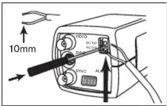
Power
Low voltage versions High voltage versions
text_image
10mm VIDEO DC: 12V AC: 52V SVHG SYNC ALAB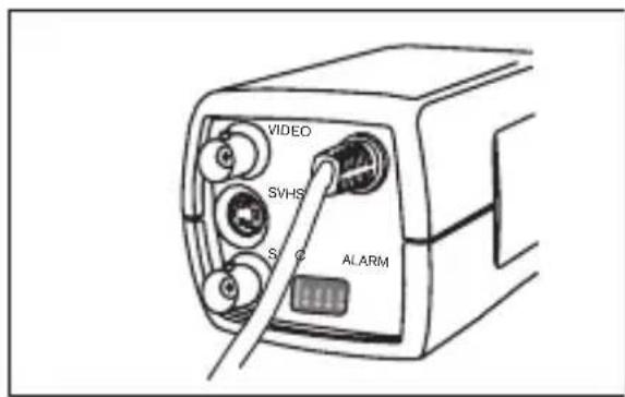
text_image
VIDEO SVHS S C ALARMFor low voltage cameras:
- push in the tabs to open the quick-connectors (these connections are not polarity sensitive).
- use AWG16 to 22 stranded wire or AWG16 to 26 solid wire; cut back 10mm (0.4") of insulation.
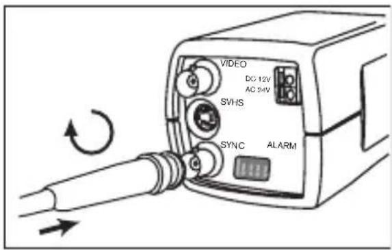
Composite video
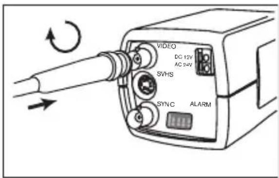
text_image
VIDEO DC 12V AC 24V SVHS SYNC ALARM
text_image
VIDEO SVHS S C ALARMSync
text_image
VIDEO DC 12V AC 24V SVHS SYNC ALARM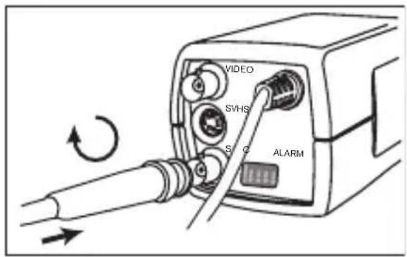
text_image
VIDEO SVHS S C ALARMY/C
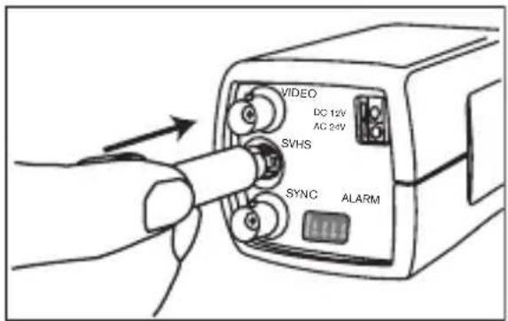
text_image
VIDEO DC 12V AC 24V SVHS SYNC ALARM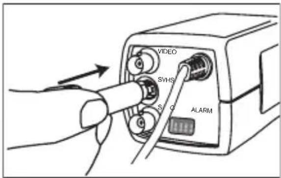
text_image
VIDEO SVHS S Q ALARM| Pin Y/C socket | |
| 1 | GND Y |
| 2 | GND C |
| 3 | Y |
| 4 | C |
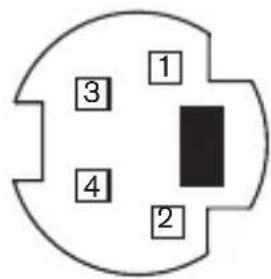
text_image
1 3 4 2Alarm connector
| Pin Alarm socket |
| 1 Alarm in Ground |
| 2 Alarm in |
| 3 Relay put contact 1 |
| 4 Relay put contact 2 |
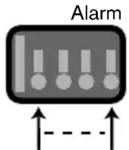
text_image
AlarmPin 1 Pin 4
- Max. wire diameter AWG 22-28 for both stranded and solid
- Default relay position n.o. (normally open), no alarm
- Alarm output relay switching capability: Max voltage 30VAC or +40VDC. Max 0.5 A continuous, 10VA.
- Alarm in: TTL logic, +5V nominal, +40VDC max, DC coupled with 22kΩ pull-up to +3.3V
- Alarm in: configurable as active low or active high
- Max. 42V allowed between camera ground and each of the relay pins.
Lens mounting
The camera accepts CS-mount lenses. C-mount lenses can be mounted using the lens adapter ring. DC-iris lenses are recommended for the best picture performance. The camera automatically detects the type of lens used and optimizes performance accordingly. A spare male lens connector is provided.

Caution
To avoid damaging the CCD sensor when using a C-mount lens, make sure the supplied lens adapter ring is mounted onto the camera before mounting the lens.
Lenses weighing more than 0.5 kg (1.1lbs) must be separately supported.
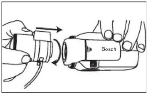
text_image
Bosch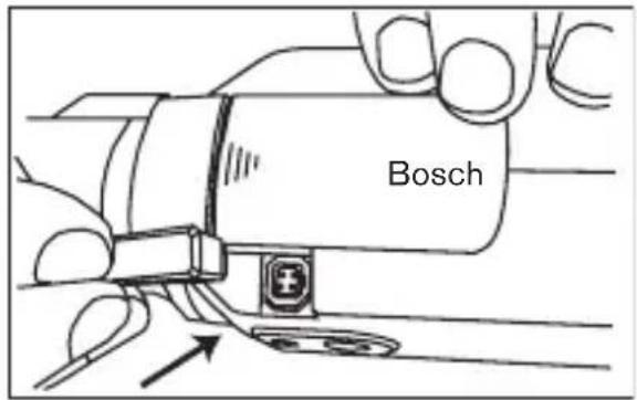
text_image
BoschPin Video iris lens DC iris lens
1 Supply (11.5V ±0.5, 50mA max.) Damp -
2 Not used Damp +
3 Video signal 1Vpp 1kOhm Drive +
4 Ground Drive -
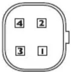
text_image
4 2 3 1Note
If a short circuit is detected on the lens connector, the on-screen display (OSD) failure message LENS SHORT CIRCUIT is shown. The lens circuit is automatically disabled to avoid internal damage. Remove the lens connector and check the pin connections.
Back focus adjustment
To optimize picture sharpness in both bright and low-level lighting, adjust the back focus. Use the camera's unique Lens Wizard (see Advanced Setup). This ensures that the object of interest always remains in focus even when focusing at the maximum lens opening.
When back focusing vari-focus lenses, adjust to obtain a sharp picture in both wide-angle and tele positions for both far and near focus.
When back focusing zoom lenses, ensure the object of interest remains in focus throughout the entire zoom range of the lens.
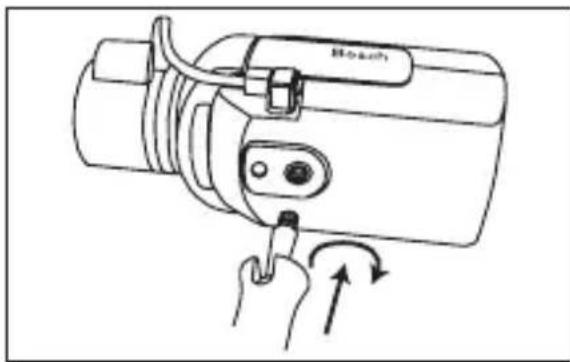
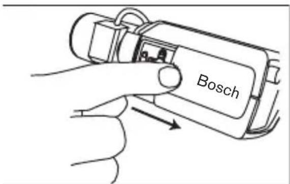
To adjust back focus:
-
Open the slide door at the side of the camera
-
Unlock the back focus locking button.
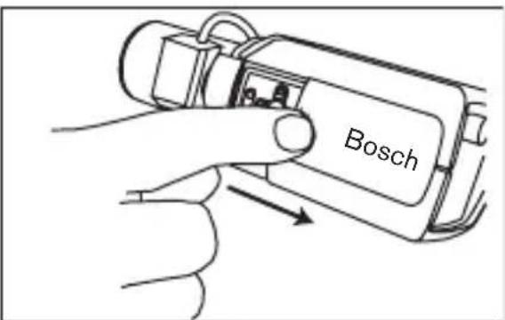
text_image
Bosch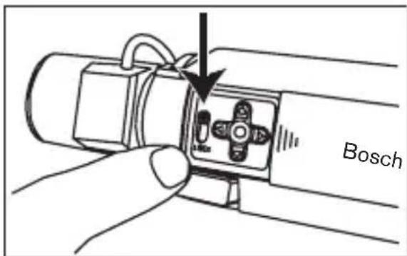
text_image
Bosch- Turn the back focus adjustment as required.
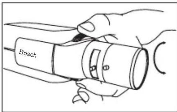
text_image
Bosch- Lock the back focus locking button.
Mounting the camera
The camera can be mounted from the top or bottom. The bottom mounting is isolated from ground. With outdoor scenes, a DC-iris lens is recommended.
natural_image
Line drawing of a Bosch remote control device with a hand inserting a screwdriver (no text or symbols)
Caution
Do not point the camera/lens into direct sunlight.
Day/Night switching
The Dinion ^XF Day/Night Camera is equipped with a motorized IR filter. The IR filter can be removed in low-light or IR illuminated applications. If Auto switching mode is selected, the camera automatically switches the filter depending on the observed light level. The switching level is programmable. In Auto switching mode the camera prioritizes motion (the camera gives sharp images without motion blur as long as the light level permits) or color (the camera gives color pictures as long as the light level permits). The camera recognizes IR illuminated scenes to prevent unwanted switching to color mode.
There are four different methods of switching:
• via the alarm input,
• via Bilinx ^TM communication,
• as part of the programmable mode profile, or
• automatically, based on the observed light levels.
Advanced Set-up
The Dinion ^XF Day/Night normally provides an optimal picture without the need for further adjustments. However, advanced set-up options are available for getting the best results from the camera under special circumstances. There are two main menus; a Mode menu and an Installer menu.
The camera has three pre-programmed operating modes that can be selected in the Mode menu. These modes are pre-programmed by default but you can adjust them according to your preferences. The Mode menu allows you to select and set-up the picture enhancement functions for each mode. If you are not happy with your changes, you can always recall the default values for the mode.
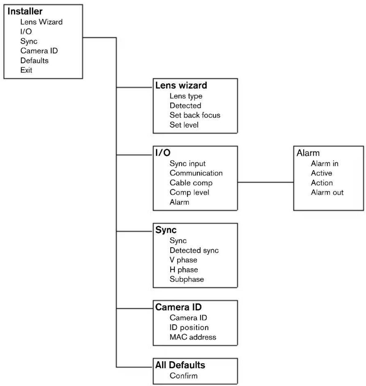
The camera also has an Installer menu in which the installation settings can be set.
The Mode and Installer menus have functions that can be selected directly or submenus for more detailed set-up.
Accessing and navigating menus
Five keys, located behind the side panel, are used for navigating through the various menus.
To access the set-up menus, press the menu/select key (center).
text_image
Bosch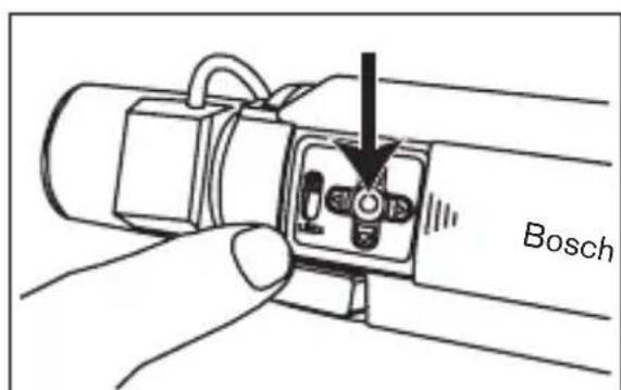
text_image
BoschThe main menu appears on the OSD. Use the arrow keys for navigation.
When the Bilinx ^™ communications link is active, the buttons on the camera are disabled. You can also set up Bilinx ^™ so that the camera buttons remain disabled even when Bilinx ^™ is not actively controlling the camera. This prevents unauthorized change of the camera settings.
Menu Structure
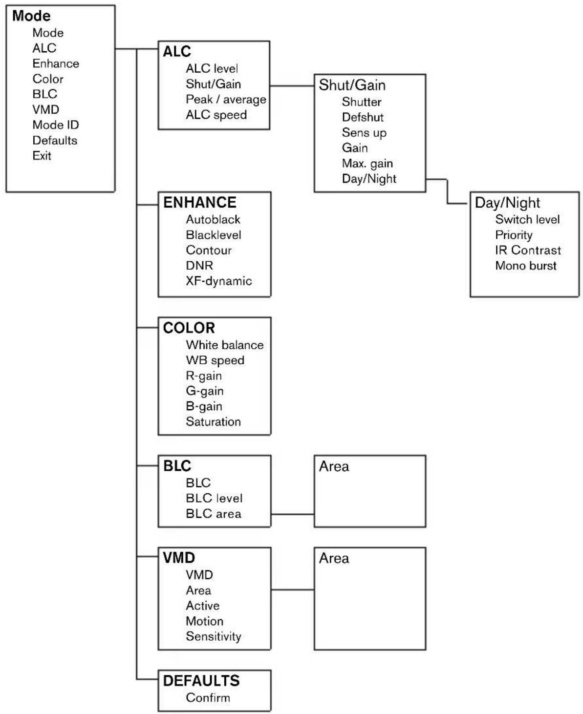
flowchart
graph TD
    A["Mode\nMode\nALC\nEnhance\nColor\nBLC\nVMD\nMode ID\nDefaults\nExit"] --> B["ALC\nALC level\nShut/Gain\nPeak / average\nALC speed"]
    B --> C["Shut/Gain\nShutter\nDefshut\nSens up\nGain\nMax. gain\nDay/Night"]
    C --> D["Day/Night\nSwitch level\nPriority\nIR Contrast\nMono burst"]
    A --> E["ENHANCE\nAutoblack\nBlacklevel\nContour\nDNR\nXF-dynamic"]
    A --> F["COLOR\nWhite balance\nWB speed\nR-gain\nG-gain\nB-gain\nSaturation"]
    A --> G["BLC\nBLC\nBLC level\nBLC area"]
    G --> H["Area"]
    A --> I["VMD\nVMD\nArea\nActive\nMotion\nSensitivity"]
    I --> J["Area"]
    A --> K["DEFAULTS\nConfirm"]
flowchart
graph TD
    A["Installer\nLens Wizard\nI/O\nSync\nCamera ID\nDefaults\nExit"] --> B["Lens wizard\nLens type\nDetected\nSet back focus\nSet level"]
    A --> C["I/O\nSync input\nCommunication\nCable comp\nComp level\nAlarm"]
    C --> D["Alarm\nAlarm in\nActive\nAction\nAlarm out"]
    A --> E["Sync\nSync\nDetected sync\nV phase\nH phase\nSubphase"]
    A --> F["Camera ID\nCamera ID\nID position\nMAC address"]
    A --> G["All Defaults\nConfirm"]
Hints for menu navigation
How to use the 5 keys

text_image
Up key Menu/select key Left key Lock Right key Down key- Press the menu/select key to access the menus or to move to the next or previous menu.
- Press the menu/select key for approximately 1.5 seconds to open the Installer menu.
- Use the up or down keys to scroll up or down through a menu.
- Use the left or right keys to move through options or to set parameters.
- When in a menu, quickly pressing the menu/select key twice restores the selected item to its factory default.
• To close all menus at once from any menu, select the Exit item and hold down the menu/select key until the menu display disappears.
Mode menu
| Function Selection Description | ||
| MODE 1, 2, 3 | Select operating mode | |
| ALC Select submenu | Select to access the video level control menu | |
| ENHANCE Select | submenu Select to access the picture enhancement menu | |
| COLOR Select | submenu Select to access the color control menu | |
| BLC ON, OFF, Select submenu | •To enable Back Light Compensation (BLC) operation set to ON•Select to access the BLC menu | |
| VMD OFF, SIL, OSD Select submenu | •To enable Video Motion Detection (VMD) operation set to SIL (silent) or OSD (monitor alarm generates on-screen message)•Select to access the VMD menu | |
| MODE ID 10 | character string Ed | table name for the selected mode |
| DEFAULTS | Select submenu | Return all settings for the selected mode to factory defaults |
| EXIT | Exit the menu | |
ALC submenu
| Function Selection Description | ||
| ALC LEVEL | -15 - 0 - +15 | Adjusts the video output level |
| SHUTGAIN | Select submenu | Select to access the Shutter and Gain control menu |
| PEAK AVERAGE | -15 - 0 - +15 | Adjust the balance between peak and average video control |
| ALC SPEED | Slow, Medium, Fast | Adjust the speed of the video level control loop. |
| EXIT | Return to MODE menu | |
ALC --> Shutter/Gain submenu
| Function Selection Description | ||
| SHUTTER AES, FL, FIXED •AES - auto-shutter - the camera automaticallysets the optimum shutter speed for manual iris lenses•FL - flickerless mode avoids interference from light sources (recommended for use with video iris or DC iris lenses only)•FIXED - allows a user defined shutter speed | ||
| DEFSHUT 1/60 (1/50), 1/100,1/120, 1/250,1/500, 1/1000,1/2000, 1/5000,1/10K | Only available if SHUTTER is AES. The camera tries to maintain the selected shutter speed as long as the light level of the scene permits. | |
| FIX SHUT 1/60 (1/50), 1/100,1/120, 1/250,1/500, 1/1000,1/2000, 1/5000,1/10K | Only available if SHUTTER is FIXED. Selects shutter speed. | |
| SENSUP | OFF, 2x, 3x, ...,10x | Selects the factor by which the sensitivity of the camera is increased. |
| GAIN AGC, FIXED •In AGC mode the camera automatically sets the gain to the lowest possible value needed to maintain a good picture•In FIXED mode the gain is set at a predefined not scene dependent value | ||
| MAXGAIN | 0, 1, ... 26 | Available in AGC mode only. Selects the maximum value the gain can have during AGC operation. |
| FIXGAIN 0, 1, ... 26 Available in FIXED gain operation only. Selects the gain setting. | ||
| DAY/NIGHT | Select submenu | Select to access the day/night control menu |
| EXIT | Return to the ALC menu | |
Note
If SENS UP is active, some noise or spots may appear in the picture. This is normal camera behavior. SENS UP may cause some motion blur on moving objects.
If the camera is in monochrome mode, all color related menu items are disabled and cannot be accessed.
Day/Night submenu
| Function Selection Description | ||
| DAY/NIGHT | COLOR, MONO, AUTO | • In COLOR mode the camera will always give a color image.• In MONO mode the IR filter is removed, giving full IR sensitivity in a monochrome image.• In AUTO mode the camera switches the filter depending on the scene illumination level. |
| LEVEL | -15 - 0 - +15 | To set the video level at which the camera switches to monochrome operation in AUTO DAY/NIGHT mode. |
| PRIORITY | COLOR, MOTION | In AUTO mode:• COLOR: the camera gives a color image as long as the light level permits.• MOTION: the camera avoids motion blur as long as the light level permits. |
| IR CONTRAST | NORMAL, ENHANCED | • In ENHANCED mode the camera will optimize contrast in applications with high IR illumination levels.• In NORMAL mode the camera will optimize contrast in mono application with visible light illumination. |
| MONO BURST | ON, OFF • If selected OFF The Color Burst in the video signal is switched OFF in monochrome mode of the camera.• If selected ON the Color Burst remains active even in Monochrome mode of the camera. | |
| EXIT Return to Shutter/Gain | submenu. | |
Enhance submenu
| Function Selection | Description | |
| AUTO BLACK ON, | OFF Autoblack ON automatically increases the visibility of details | |
| BLK LEVEL | -50, ... 0, ...+50 | Adjusts the black level between 0 and approx 110mV. Zero position of slider corresponds to the factory default black level |
| CONTOUR | -15 - 0 - +15 | Adjusts the sharpness of the picture. 0 corresponds to the default position. |
| DNR (dynamic noise reduction) | AUTO, OFF | In AUTO mode the camera automatically reduces the noise in the picture. This may cause some motion blur on moving objects. |
| XF-DYN (dynamic range enhancement) | OFF, LOW, MID, HIGH | In XF-DYN mode the camera automatically optimizes the contrast in the picture. |
| EXIT | Return to Mode menu | |
Color submenu
| Function Selection Description | ||
| WHITE BALANCE | ATW, MANUAL, AWB HOLD | •ATW: Auto tracking white balance allows the camera to constantly adjust for optimal color reproduction.•AWB HOLD: Puts the ATW on hold and saves the color settings.•In MANUAL mode the Red, Green and Blue gain can be manually set to a desired position |
| WB SPEED | Slow, Medium, Fast Adjust the speed of the white balance control loop. | |
| RED gain -5 | 0 - +5 •ATW mode and AWB hold mode: adjusts the Red gain to optimize the white point. | |
| BLUE gain | -5 - 0 - +5 | •ATW mode and AWB hold mode: adjusts the B gain to optimize around the white point. |
| RED GREEN BLUE | -50 - 0 - +50 Controls all the colors individually for manual white balance only. | |
| SAT | +15, ... 0, ... +5 | Adjusts the color saturation. -15 will lead to a monochrome image |
| EXIT Return to Mode menu | ||
Back Light Compensation (BLC) submenu
| Function Selection Description | ||
| BLC | ON, OFF | When ON, the video level is optimized for the selected area of the image. Parts outside this area may be underexposed or overexposed (this is normal). |
| BLC LVL | -15,..0,..+15 | BLC LEVEL adjust the balance between the selected BLC area and its surrounding. |
| AREA | Select submenu | Select to access the Back Light Compensation area menu (see selecting an area). |
| EXIT | Return to Mode menu | |
Selecting an area
To set-up an area for BLC (or VMD), access the area menu by selecting the AREA option from the BLC (or VMD) menu. Upon entering the AREA
menu, the current area is displayed with the upper left corner flashing. The flashing corner of the image can be moved with the Up, Down, Left, Right arrow keys. Pressing the Select key moves the flashing cursor to the opposite corner, which can now be moved. Pressing Select again freezes the area and exits the area menu.
Video Motion Detection (VMD) submenu
| Function Selection Description | ||
| VMD OFF, SIL, OSD When VMD is enabled and the camera can generate SIL (silent) or OSD (monitor alarm generates on-screen message) motion alarms. | ||
| AREA 1, 2, 3 | 4,Select submenu | •It is possible to set 4 motion sensitive areas (per MODE).•Press SELECT to enter the area set-up menu. |
| ACTIVE ON, | OFF Every area can be enabled individually by selecting YES. | |
| MOTION Press SELECT to reset indicator | Indicates the peak of measured motion in the selected area | |
| SENS Use the LEFT/RIGHT keys to set the SENSitivity for motion to the desired level. Motion above this level triggers alarm. | ||
| EXIT Return to Mode menu | ||
Note
If VMD areas overlap, motion is only detected in the area with the lowest sequence number.
Defaults submenu
| Function Selection Description | ||
| MODE DEFAULTS | Select to restore the factory defaults. A confirmation screen appears. Allow 5 seconds for the camera to optimize the picture after a mode reset. | |
| EXIT Return to Mode menu | ||
Installer Settings
Install menu
| Function Selection Description | ||
| LENS WIZARD | Select submenu Select to optimize camera lens combination | |
| I/O Select sub | bmenu Select to access the I/O functions | |
| SYNC Select | submenu Select to access the synchronization functions | |
| CAMERA ID | Select submenu Select to access ID menu | |
| DEFAULTS S | select submenu Return all settings for all modes to factory defaults | |
| EXIT Exit the | menu | |
Install lens wizard submenu
| Function Selection Description | ||
| LENS TYPE | AUTO, MANUAL, DCIRIS, VIDEO | In AUTO mode the camera auto detects the type of lens used or force the camera into a mode. |
| DETECTED | If the LENS TYPE detection is in AUTO, the detected lens type will be shown. | |
| SET BACK FOCUS NOW | Select to force lens to its maximum opening. After focusing the lens the object of interest remains in focus in bright and low light conditions. | |
| SET LVL (Video iris lenses only). The level detector indicator must be set to the center by adjusting the level potentiometer on the lens, to obtain the best picture performance. | ||
| EXIT Return to the INSTALL menu | ||
Adjustment procedure DC-iris Lens:
- Unlock the back focus locking button.
- Access the Lens Wizard menu.
- SET BACK FOCUS NOW is highlighted in the menu.
- Turn the back focus adjustment as required.
- Lock the back focus locking button.
- Exit the menu.
Adjustment procedure Manual-iris Lens:
- Unlock the back focus locking button.
- Adjust the lens to the maximum lens opening.
- Turn the back focus adjustment as required.
- Lock the back focus locking button.
Adjustment procedure Video-iris Lens:
- Unlock the back focus locking button.
- Access the Lens Wizard menu.
- SET BACK FOCUS NOW is highlighted in the menu.
- Turn the back focus adjustment as required.
- Lock the back focus locking button.
- Select SET LVL in the menu; the LEVEL bar appears.
- Point the camera at the scene it will be mostly viewing.
- Adjust the level potentiometer located on the lens until the LEVEL bar is in the central position.
- Exit the menu.
Note
The best performance with video iris lenses is obtained when the peak/average potentiometer of the lens is set to either full average or full peak matching the position of the peak/average balance in the MODE x ALC menu.
Install I/O submenu
| Function Selection Description | ||
| SYNC IN 75 | Ohm, HIGH Select 75 | Ohm if the external sync input is not terminated elsewhere. |
| COMM ON, | OFF If OFF, Bilinx communication is disabled. | |
| CABLE COMP | OFF, DEFAULT, RG59, COAX12, COAX6 | Cable compensation is used to avoid the need for amplifiers in long distance coax connections up to 1000m (3000ft). For optimum results select the coaxial cable type used or if unknown, DEFAULT. |
| COMP LEVEL | 0, 1, .. +15 Sets the level of cable compensation. | |
| ALARM Select submenu | ||
| EXIT Return to the INSTALL menu | ||
Install I/O --> Alarm submenu
| Function Selection Description | ||
| ACTIVE NONE, HIGH, LOW | Selects active_HIGH or active_LOW for the alarm input connector. Select NONE to disable alarm switching. | |
| ACTION NONE, MONO, MODE1, MODE2, MODE3 | Selects the operating mode of the camera upon switching the alarm input. | |
| ALARM OUT | VMD, REMOTE, DAY/NIGHT, FILTER MOVE | •Select VMD to close the output relay upon VMD alarms.•Select REMOTE to make the output relay available to remote communication devices.•Day/night: the alarm output relay closes if the camera operates in monochrome mode.•Filter move: the alarm output relay closes before the filter starts moving (in either direction) and opens when the video level has stabilized (2 - 3 seconds). |
| EXIT Return to the I/O menu | ||
Install sync submenu
| Function Selection Description | ||
| SYNC INTERNAL, LINE LOCK, HV LOCK, GENLOCK | Select INTERNAL for free running camera operation, select LINE LOCK to lock to the power supply frequency, select HV LOCK to lock to the signal supplied to the external sync input, select GENLOCK to lock the subcarrier as well. | |
| DETECTED SYNC | Shows the actual sync mode used by the camera. | |
| VPHASE 0, 2, ... 358 Adjusts the vertical phase offset (when in LINE LOCK mode and a valid power supply frequency is detected). | ||
| HPHASE -25, ..., 0, ... +125 | Adjust the horizontal phase offset (when in EXT lock mode and a valid input signal is detected) | |
| SUB PHASE | 0, 2, ... 358 Adjusts the sub-carrier phase offset (when in EXT LOCK mode and a valid sub-carrier is detected). | |
| EXIT Return to the INSTALL menu | ||
Note
VPHASE, HPHASE and SUB-PHASE cannot be accessed if there is no valid locking signal.
Install ID submenu
| Function Selection Description | ||
| CAMERA ID | Enter a 16 character c | camera name string. Use LEFT/RIGHT to change position in the string, use UP/DOWN to select the character. Use SELECT to exit the string edit screen. |
| ID POS | OFF, TOP, BOT | Select TOP to display the camera ID in the upper left corner; select BOT for the lower left corner. The ID string is not displayed when the OSD menus are open. |
| EXIT Return to the INSTALL menu | ||
Defaults submenu
| Function Selection Description | ||
| ALL DEFAULTS | Select to restore the factory defaults. A confirmation screen appears. Allow 5 seconds for the camera to optimize the picture after a mode reset. | |
| EXIT Return to Mode menu | ||
Camera Control Communication
This camera is equipped with a coaxial communications transceiver. In combination with VP-CFGSFT, the camera can be adjusted from the head-end side of the coaxial cable. All menus can be accessed remotely giving full control of the camera. With this communication it is also possible to disable the local keys on the camera.
To avoid loss of communication on an installed camera, the COMMUNICATION ON/OFF selection is NOT available while using remote control. This function can only be accessed with the camera buttons.
Technical specification
1/2" CCD versions
| Type number LTC | 0620/11 | LTC0620/21 | LTC0620/51 | LTC0620/61 |
| Standard PAL NTSC PAL NTSC | ||||
| Active pixels 752x582 768x492 752x582 768x492 | ||||
| Rated supply voltage | 24 VAC or 12 VDC12-28 VAC (50/60 Hz)11-36 VDC | 230 VAC 50Hz, (/50)110 VAC 60Hz, (/60)Range: 100-230 VAC ±10%50/60Hz | ||
| Min illumination < | 0.18 lux< 0.024 lux (in monochrome mode) | |||
1/3" CCD versions
| Type number LTC | 0495/11 | LTC0495/21 | LTC0495/51 | LTC0495/61 |
| Standard PAL NTSC PAL NTSC | ||||
| Active pixels 752x582 768x492 752x582 768x492 | ||||
| Rated supply voltage | 24 VAC or 12 VDC12-28 VAC (50/60 Hz)11-36 VDC | 230 VAC 50Hz, (/50)110 VAC 60Hz, (/60)Range: 100-230 VAC ±10%50/60Hz | ||
| Min illumination < | 0.24 lux< 0.038 lux (in monochrome mode) | |||
All versions
| Imager Interline CCD | |
| Resolution | 540 TVL |
| SNR | >50 dB |
| Video output | 1 Vpp, 75 Ohm |
| Y/C output Y: 1 Vpp | C: 0.3 Vpp |
| Synchronization | Internal, HV-lock, Genlock or Line Lock selectable |
| Shutter | AES (1/60 (1/50) to 1/100000), Flickerless, Fixed selectable |
All versions
| Day/Night Color, Mono, Auto | |
| Sens Up Adjustable from OFF to 10x | |
| Auto black On, Off selectable (maximum level selectable up to 28dB) | |
| AGC AGC on or off (0 dB) selectable | |
| XF-DYN Automatic dynamic range enhancement level selectable | |
| DNR Automatic noise filtering ON/OFF selectable | |
| Contour Sharpness enhancement level selectable | |
| BLC BLC On or Off selectable, with programmable area | |
| White balance Automatic 2500 - 9000K (with AWB hold mode and manual mode) | |
| Color saturation Adjustable from monochrome (0%) to 133% color | |
| Lens Mount CS compatible, C-mount compatible with supplied adapter ring | |
| ALC lens Video or DC iris auto detect | |
| Power consumption | < 5 W |
| Dimensions 58 x 66 x 122 mm (HxWxL) without lens | |
| Weight 450g without lens | |
| Tripod Mount Bottom (isolated) and Top 1/4" 20 UNC | |
| Operating temperature | -20° to 50°C |
| Controls OSD with softkey operation | |
Accessories
Power transformers
• TC1334 120VAC, 60Hz - 24VAC, 30VA
• TC120PS 120VAC, 60Hz - 15VDC, 9VA
• TC220PSX-24 220-240VAC, 50/60Hz - 24VAC, 30VA
• TC220PS 220-240VAC, 50/60Hz - 15VDC, 9VA
Interface box:
- VP-CFGSFT Bilinx™ communication interface box and software
Recommended lenses
Varifocal lenses:
• LTC 3264/30 1/2" DC-iris, 4.5-10mm F1.6-360
• LTC 3274/40 1/2" DC-iris, 7.5-75mm F2.2-360
• LTC 3364/21 1/3" DC-iris, 2.8-6mm F1.4-300 - IR
• LTC 3364/31 1/3" DC-iris, 3.5-8mm F1.4-300 - IR
• LTC 3364/40 1/3" DC-iris, 2.8-12mm F1.4-360
• LTC 3374/20 1/3" DC-iris, 5-50mm F1.4-185
Zoom lenses:
• LTC 3283/20 1/2" Video iris, 8-48mm F1.4-360
• LTC 3384/21 1/3" DC-iris, 6-60mm F1.4-360
© 2004 Bosch Security Systems B.V.
Subject to change. Printed in Portugal.
3122 165 23061