
Synergy 480 G9 - Server HP - Free user manual and instructions
Find the device manual for free Synergy 480 G9 HP in PDF.


| Product Type | Blade Server |
| Brand | Hewlett Packard Enterprise (HPE) |
| Model | Synergy 480 Gen9 (G9) |
| Form Factor | Synergy 12000 Frame (half-height blade) |
| Processor | Intel Xeon Scalable (2nd Gen), up to 28 cores |
| Memory | DDR4 ECC, up to 3 TB (24 slots) |
| Storage | Up to 10 SFF hot-plug SAS/SATA/SSD |
| Networking | HPE FlexibleLOM or Mezzanine adapters (10/25/100GbE) |
| Management | HPE OneView, iLO 5 (dedicated management port) |
| Power Supply | HPE Common Slot power supplies (redundant, up to 2400W) |
| Cooling | Shared frame cooling with high-efficiency fans |
| Dimensions (blade) | 203.2 x 444.5 x 57.9 mm (H x W x D) |
| Weight (approx) | 7.5 kg (16.5 lb) |
| Operating Temperature | 10°C to 35°C (50°F to 95°F) |
| Operating Humidity | 20% to 80% non-condensing |
| Certifications | CE, FCC, RoHS, WEEE |
| Warranty | 3-year limited warranty (parts, labor, on-site) |
Frequently Asked Questions - Synergy 480 G9 HP
User questions about Synergy 480 G9 HP
0 question about this device. Answer the ones you know or ask your own.
Ask a new question about this device
Download the instructions for your Server in PDF format for free! Find your manual Synergy 480 G9 - HP and take your electronic device back in hand. On this page are published all the documents necessary for the use of your device. Synergy 480 G9 by HP.
USER MANUAL Synergy 480 G9 HP
This document is for the person who installs, administers, and troubleshoots the HPE Synergy system. Hewlett Packard Enterprise assumes you are qualified in the servicing of computer equipment and trained in recognizing hazards in products with hazardous energy levels.
text_image
* 8 1 3 1 6 9 - 0 0 2 *Part Number: 813169-002
Published: March 2017
Edition: 2
Notices
The information contained herein is subject to change without notice. The only warranties for Hewlett Packard Enterprise products and services are set forth in the express warranty statements accompanying such products and services. Nothing herein should be construed as constituting an additional warranty. Hewlett Packard Enterprise shall not be liable for technical or editorial errors or omissions contained herein.
Confidential computer software. Valid license from Hewlett Packard Enterprise required for possession, use, or copying. Consistent with FAR 12.211 and 12.212, Commercial Computer Software, Computer Software Documentation, and Technical Data for Commercial Items are licensed to the U.S. Government under vendor's standard commercial license.
Links to third-party websites take you outside the Hewlett Packard Enterprise website. Hewlett Packard Enterprise has no control over and is not responsible for information outside the Hewlett Packard Enterprise website.
Contents
Component identification.... 6
Front panel LEDs and buttons....6
Front panel components....7
Serial label pull tab information....7
Drive numbering....7
Hot-plug drive LED definitions....8
SFF flash adapter components and LED definitions....9
NVMe SSD components....10
System board components....11
System maintenance switch.... 11
Mezzanine connector definitions.... 12
DIMM slot locations.... 13
Components.... 14
LEDs....14
Component and LED identification for HPE Synergy hardware.... 15
Operations....16
Powering up the compute module 16
Powering down the compute module 16
Removing the drive blank....16
Removing the compute module....17
Removing the compute module end cap....18
Removing the access panel.... 18
Removing the DIMM baffle....19
Removing the front panel/drive cage assembly....20
Installing the compute module end cap....20
Installing the access panel....21
Installing the DIMM baffles....21
Installing the front panel/drive cage assembly....21
Setup....23
Installation overview....23
Installing the compute module options....23
Installing the compute module....23
Completing the configuration....25
Hardware options installation.... 26
Introduction....26
Installing the drive option....26
Installing the SFF flash adapter option....28
Installing the controller option....28
Installing the HPE Smart Storage Battery option....29
Installing the mezzanine card options.... 30
Installing the HPE Smart Array P542D Controller mezzanine option.... 31
Memory options....32
SmartMemory....33
Memory subsystem architecture....33
DIMM ranks 34
DIMM identification 34
Memory configurations.... 35
Advanced ECC memory configuration....36
Online Spare memory configuration.... 36
General DIMM slot population guidelines 36
Advanced ECC population guidelines....37
Online spare population guidelines....37
Population order....37
Installing a DIMM....37
Installing the processor option....38
HP Trusted Platform Module option....42
Installing the Trusted Platform Module board 43
Retaining the recovery key/password....44
Enabling the Trusted Platform Module....44
Cabling....46
Cabling resources....46
HPE Smart Storage Battery cabling....46
HPE Smart Array P542D Controller cabling....46
Software and configuration utilities....47
Management and diagnostic tools....47
Removing and replacing the system battery.... 48
Warranty and regulatory information....49
Warranty information....49
Regulatory information....49
Safety and regulatory compliance....49
Belarus Kazakhstan Russia marking....49
Turkey RoHS material content declaration.... 50
Ukraine RoHS material content declaration....50
Electrostatic discharge.... 51
Preventing electrostatic discharge....51
Grounding methods to prevent electrostatic discharge....51
Specifications.... 52
Environmental specifications 52
Compute module specifications....52
Documentation and troubleshooting resources for HPE Synergy...... 53
HPE Synergy documentation....53
HPE Synergy Configuration and Compatibility Guide....53
HPE OneView User Guide for HPE Synergy....53
HPE OneView Global Dashboard....53
HPE Synergy Image Streamer User Guide 53
HPE Synergy Image Streamer GitHub.... 53
HPE Synergy Software Overview Guide.... 53
Best Practices for HPE Synergy Firmware and Driver Updates.... 54
HPE OneView Support Matrix for HPE Synergy....54
HPE Synergy Image Streamer Support Matrix.... 54
HPE Synergy Glossary....54
HPE Synergy troubleshooting resources....54
Troubleshooting within HPE OneView....54
HPE Synergy Troubleshooting Guide....54
HPE Error Message Guide for HPE Synergy.... 55
HPE OneView and HPE OneView REST API scripting help.... 55
HPE Synergy QuickSpecs....55
Support and other resources.... 56
Accessing Hewlett Packard Enterprise Support....56
Information to collect....56
Accessing updates....56
Websites....56
Customer Self Repair 57
Remote support....63
Acronyms and abbreviations.... 64
Documentation feedback...... 66
Component identification
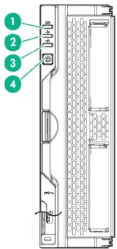
Front panel LEDs and buttons
text_image
1 2 3 4| Item Description Status | |
| 1 UID LED | Solid blue = ActivatedFlashing blue (1 Hz/cycle per sec) = Remote management or firmware upgrade in progressOff = Deactivated |
| 2 Health status LED | Solid green = NormalFlashing green (1 Hz/cycle per sec) = iLO is rebootingFlashing amber = System degradedFlashing red (1 Hz/cycle per sec) = System critical |
| 3 Mezzanine NIC status LED | Solid green= Link on any Mezzanine NICFlashing green= Activity on any Mezzanine NICOff = No link or activity on any Mezzanine NIC |
| 4 Power On/Standby button and system power LED | Solid green = System onFlashing green (1 Hz/cycle per sec) = Performing power on sequenceSolid amber = System in standbyOff = No power present* |
*If all other LEDs are off, then no power is present to the compute module. If the health LED is flashing green while the system power LED is off indicates that the Power On/Standby button service is initializing or that an
iLO reboot is in progress.*Facility power is not present, power cord is not attached, no power supplies are installed, power supply failure has occurred, or the power button cable is disconnected.
Front panel components
text_image
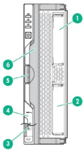
Diagram of a server rack with numbered components for identificationItem Description
| 1 Drive bay 1* |
| 2 Drive bay 2* |
| 3 External USB 3.0 connector (behind the serial label pull tab) |
| 4 Serial label pull tab |
| 5 Compute module handle release latch |
| 6 Compute module handle |
*If uFF drives (the SFF Flash Storage Adapter) are installed in the drive bays, the drive bay numbering is different. For more information, see Drive numbering.
Serial label pull tab information
The serial label pull tab is located on the front panel of the compute module. To locate the serial label pull tab, see Front panel components. The serial label pull tab provides the following information:
- Product serial number
• HPE HPE iLO information - QR code that points to mobile-friendly documentation
Drive numbering
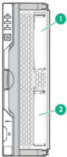
Depending on the configuration, this compute module can support hard drives, SSDs, NVMe drives, and uFF drives (supported in dual SFF flash adapters) in the drive bays. Depending on the device installed, the bay number might be different.
text_image
Diagram of a server rack with labeled components, showing internal structure and numbered parts.| Item Hard drive/SSD baynumbering | uFF drive baynumbering | NVMe drive baynumbering |
| 1 1 1 and 101 1 | ||
| 2 2 2 and 102 2 |
Hot-plug drive LED definitions
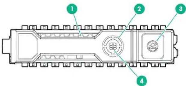
text_image
1 2 3 4| Item LED Status Definition | |
| 1 Locate Solid blue The drive is being identified by a host application. | |
| Flashing blue The drive carrier firmware is being updated or requires an update. | |
| 2 Activity Ring Rotating green Drive activity | |
| Off No drive activity | |
| 3 Do not remove Solid white Do not remove the drive. Removing the drive causes one or more of the logical drives to fail. | |
| Off Removing the drive does not cause a logical drive to fail. | |
| 4 Drive status Solid green The drive is a member of one or more logical drives. | |
| Flashing green The drive is rebuilding or performing a RAID migration, strip size migration, capacity expansion, or logical drive extension, or is erasing. | |
| Flashing amber/ green | The drive is a member of one or more logical drives and predicts the drive will fail. |
| Flashing amber The drive is not configured and predicts the drive will fail. | |
| Solid amber The drive has failed. | |
| Off The drive is not configured by a RAID controller. | |
Table Continued
SFF flash adapter components and LED definitions
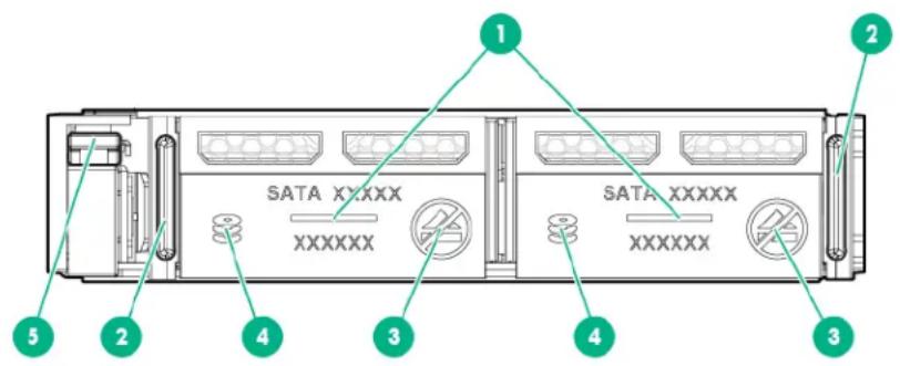
text_image
SATA XYXXX XXXXXX 1 SATA XXXXX XXXXXX 2 3 4 5 3Item Component Description
| 1 Locate | Off—NormalSolid blue—The drive is being identified by a host application.Flashing blue—The drive firmware is being updated or requires an update. |
| 2 uFF drive ejection latch Removes the uFF drive when released | |
| 3 Do not remove LED | Off—OK to remove the drive. Removing the drive does not cause a logical drive to fail.Solid white—Do not remove the drive. Removing the drive causes one or more of the logical drives to fail. |
| Item Component Description | |
| 4 Drive status LED | Off—The drive is not configured by a RAID controllerSolid green—The drive is a member of one or more logical drives.Flashing green (4 Hz)—The drive is operating normally and has activity.Flashing green (1 Hz)—The drive is rebuilding or performing a RAID migration, stripe size migration, capacity expansion, logical drive extension, or is erasing.Flashing amber/green (1 Hz)—The drive is a member of one or more logical drives that predicts the drive will fail.Solid amber—The drive has failed.Flashing amber (1 Hz)—The drive is not configured and predicts the drive will fail. |
| 5 Adapter ejection release latch and handle | Removes the SFF flash adapter when released |
Table Continued
NVMe SSD components
The NVMe SSD is a PCIe bus device. A device attached to a PCIe bus cannot be removed without allowing the device and bus to complete and cease the signal/traffic flow.

CAUTION:
Do not remove an NVMe SSD from the drive bay while the Do Not Remove button LED is flashing. The Do Not Remove button LED flashes to indicate the device is still in use. Removal of the NVMe SSD before the device has completed and ceased signal/traffic flow can cause loss of data.
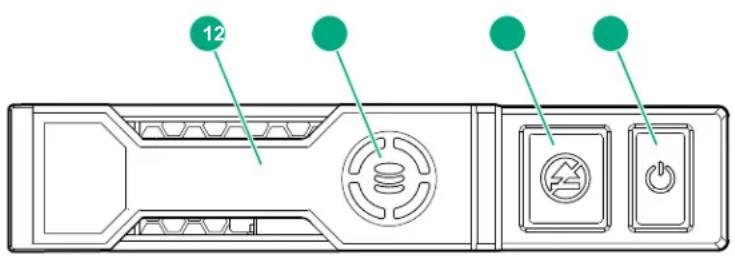
text_image
12Item Description
1 Release lever
2 Activity ring
3 Do Not Remove button
4 Power button
System board components
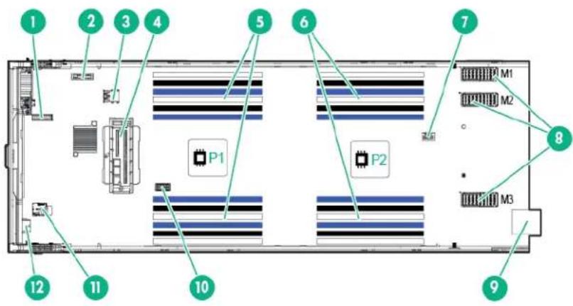
text_image
1 2 3 4 5 6 7 8 9 10 11 12 P1 P2 M1 M2 M3Item Description
1 TPM connector
2 System battery
3 Internal USB 3.0 connector
4 Drive backplane connector
5 Processor 1 DIMM slots (12)
6 Processor 2 DIMM slots (12)
9 Management/power connector
10 System maintenance switch
11 microSD card slot
12 External USB 3.0 connector
7 HPE Smart Storage Battery connector
8 Mezzanine connectors (M1, M2, and M3)
System maintenance switch
| Position Default Function | |
| S1* Off | Off = HPE iLO security is enabled. |
| On = HPE iLO security is disabled. | |
| S2 Off | Off = System configuration can be changed. |
| On = System configuration is locked. | |
| S3 Off Reserved | |
| S4 Off Reserved | |
| S5* Off | Off = Power-on password is enabled.On = Power-on password is disabled. |
| S6* ** Off | Off = No functionOn = Restore default manufacturing settings |
| S7 Off | Off = Set default boot mode to UEFI.On = Set default boot mode to legacy. |
| S8 — Reserved | |
| S9 — Reserved | |
| S10 — Reserved | |
| S11 — Reserved | |
| S12 — Reserved | |
Table Continued
*You can access the redundant ROM by setting S1, S5, and S6 to On.
IMPORTANT:
Before using the S7 switch to change to Legacy BIOS Boot Mode, be sure the HPE Dynamic Smart Array B140i Controller is disabled. Do not use the B140i controller when the compute module is in Legacy BIOS Boot Mode.
Mezzanine connector definitions
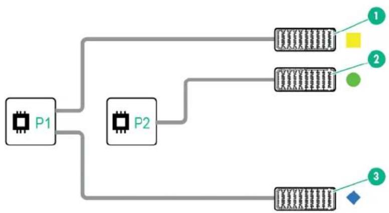
flowchart
graph TD
    P1["Chip P1"] --> P2["Chip P2"]
    P2 --> Module1["Module 1: Yellow Square"]
    P2 --> Module2["Module 2: Green Circle"]
    P2 --> Module3["Module 3: Blue Diamond"]
Item Connector identification Supported card types Fabric Supported ICM bays
1 Mezzanine connector 1 (M1)* Type C and Type D 1 ICM 1 and 4
2 Mezzanine connector 2 (M2)** Type C and Type D 2 ICM 2 and 5
3 Mezzanine connector 3 (M3) Type C only 3 ICM 3 and 6
* When an NVIDIA Tesla M6 GPU FIO Adapter for HPE Synergy 480 Gen9 Compute Module is installed in mezzanine connector 1, mezzanine connector 2 is not available for additional mezzanine cards.
** When installing a mezzanine option on mezzanine connector 2, processor 2 must be installed.
DIMM slot locations
DIMM slots are numbered sequentially (1 through 12) for each processor. The supported AMP modes use the alpha assignments for population order, and the slot numbers designate the DIMM slot ID for spare replacement.
The colored slots indicate the slot order within each channel:
- White — First slot of a channel
- Black — Second slot of a channel
• Blue — Third slot of a channel
The arrow points to the front of the compute module.
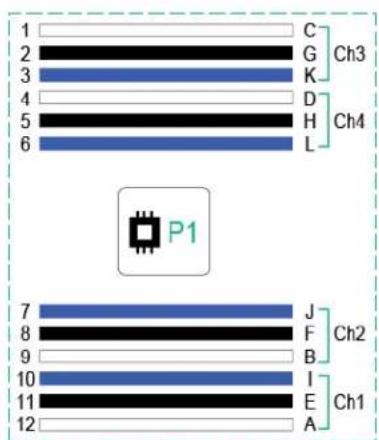
text_image
1 C Ch3 2 G 3 K 4 D Ch4 5 H 6 L P1 7 J Ch2 8 F 9 B 10 I Ch1 11 E 12 A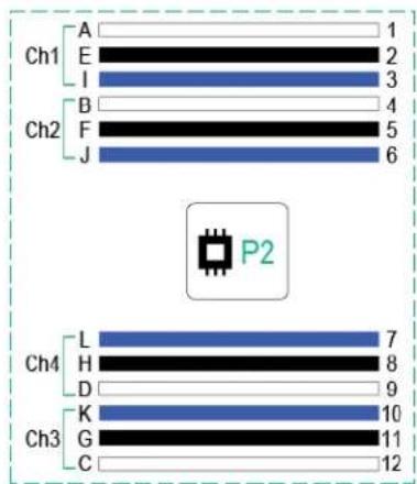
bar
| Channel | Value | |---|---| | A | 1 | | E | 2 | | I | 3 | | B | 4 | | F | 5 | | J | 6 | | L | 7 | | H | 8 | | D | 9 | | K | 10 | | G | 11 | | C | 12 | P2 is a label in the image above the bars.
Components
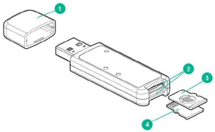
text_image
Technical diagram of a device with numbered parts, showing internal components and labeled parts.| ItemDescription |
| 1 Cap |
| 2 MicroSD card slot |
| 3 SD1 card |
| 4 SD2 card |
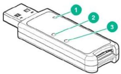
LEDs
text_image
Diagram of a device with numbered parts labeled 1, 2, and 3 pointing to specific components.| ItemDescriptionStatus | |
| 1 Power LED | Green: Device is on and at least one microSD card is functioningRed: Both microSD cards have failed |
| 2 SD2 LED | On: microSD card has failedOff: microSD card is healthy |
| 3 SD1 LED | On: microSD card has failedOff: microSD card is healthy |
Component and LED identification for HPE Synergy hardware
For more information about component and LED identification for HPE Synergy components, see the product-specific maintenance and service guide or the HPE Synergy 12000 Frame Setup and Installation Guide in the Hewlett Packard Enterprise Information Library.
Operations
Powering up the compute module
To power up the compute module, press the Power On/Standby button.
Powering down the compute module
Before powering down the compute module for any upgrade or maintenance procedures, perform a backup of critical data and programs.
IMPORTANT:
When the compute module is in standby mode, auxiliary power is still being provided to the system.
IMPORTANT:
Always attempt a graceful shutdown before forcing the shutdown of applications and the OS with a non-graceful shutdown.
To power down the compute module, use one of the following methods:
- To perform a graceful shutdown of applications and the OS when powering down the compute module to standby mode, use one of the following methods:
- Press and release the Power On/Standby button.
- Select the Momentary press power off selection in HPE OneView.
- Select the Momentary press virtual power button selection in HPE iLO.
Always attempt a graceful shutdown first before forcing the compute module to power off.
- If a graceful shutdown fails to power down the compute module to standby mode when an application or OS stops responding, use one of the following methods to force a non-graceful shutdown of applications and the OS:
- Press and hold the Power On/Standby button for more than four seconds.
- Select the Press and hold power off selection in HPE OneView.
- Select the Press and hold virtual power button selection in HPE iLO.
Application data can be lost when performing a non-graceful shutdown of applications and the OS.
Before proceeding, verify that the compute module is in standby mode by observing that the system power LED is amber.
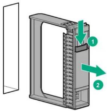
Removing the drive blank
Remove the component as indicated.
text_image
Diagram of a device with labeled components and directional arrows indicating flow or movement
CAUTION:
To prevent improper cooling and thermal damage, do not operate the compute module unless all bays are populated with either a component or a blank.
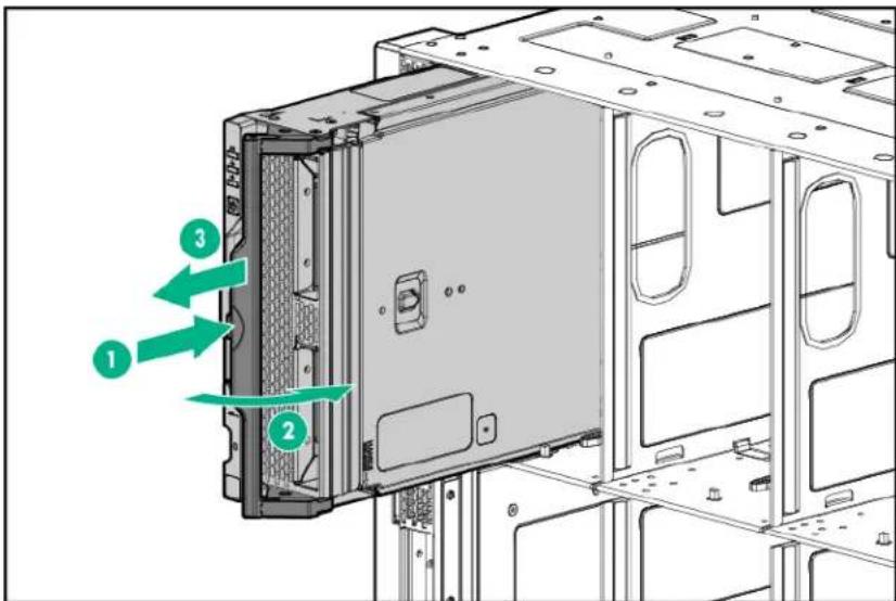
Removing the compute module
Procedure
- Identify the proper compute module.
- Power down the compute module.
- Remove the compute module.
text_image
Technical diagram of a computer drive showing labeled components and directional arrows indicating assembly or movement.- Install the compute module end cap when the compute module is outside of the frame.
- Place the compute module on a flat, level work surface.
To replace the component, reverse the removal procedure.

WARNING:
To reduce the risk of personal injury from hot surfaces, allow the drives and the internal system components to cool before touching them.

CAUTION:
To prevent damage to electrical components, properly ground the compute module before beginning any installation procedure. Improper grounding can cause ESD.
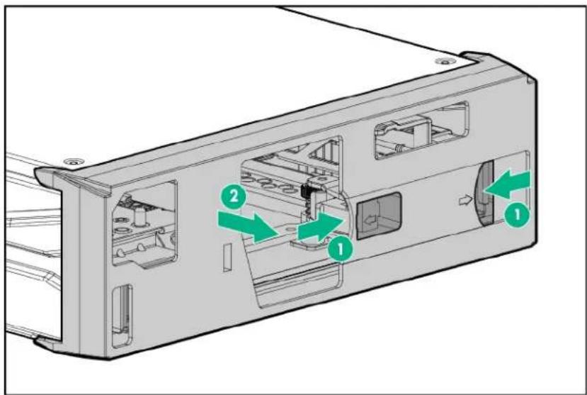
Removing the compute module end cap
Procedure
-
Place the compute module on a flat, level work surface.
-
Remove the compute module end cap.
text_image
Technical diagram of a computer case with labeled components and directional arrows indicating movement or flow.Removing the access panel
Procedure
-
Power down the compute module.
-
Remove the compute module.
-
Place the compute module on a flat, level work surface.
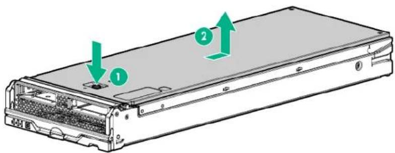
-
Press the access panel release button.
-
Slide the access panel towards the rear of the compute module, and then lift up to remove the panel.
text_image
Diagram of a server rack with labeled components and directional arrows indicating assembly or movement.Removing the DIMM baffle
Procedure
- Power down the compute module.
- Remove the compute module.
- Place the compute module on a flat, level work surface.
- Remove the access panel.
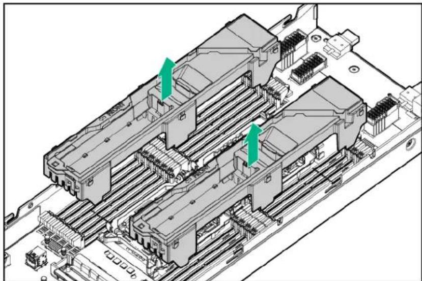
IMPORTANT:
When removing the right DIMM baffle, leave the Smart Storage Battery installed on the baffle. Use the blue pull tab to disconnect the Smart Storage Battery cable from the system board.
- Remove one or more DIMM baffles.
natural_image
Isometric view of a computer motherboard with multiple slots and connectors (no text or symbols visible)Removing the front panel/drive cage assembly
Procedure
- Power down the compute module.
- Remove the compute module.
- Place the compute module on a flat, level work surface.
- Remove the access panel.
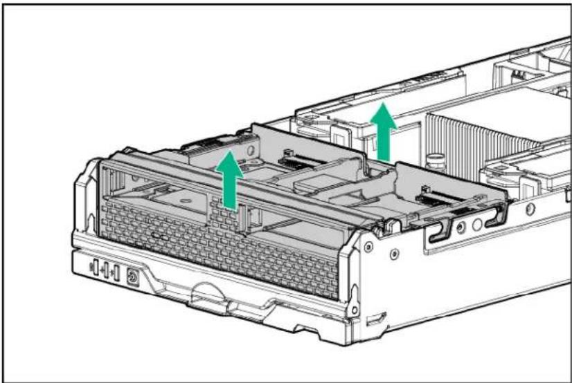
- Remove all drives.
- Remove the front panel/drive cage assembly.
natural_image
Technical diagram of an internal computer chassis showing internal components and green arrows indicating directional movement (no text or symbols present)Installing the compute module end cap
Procedure
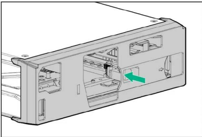
- Place the compute module on a flat, level work surface.
- Install the compute module end cap.
natural_image
Technical line drawing of a computer case with internal components and a green arrow indicating a specific part (no text or symbols present)Installing the access panel
Procedure
- Place the access panel on top of the graphics blade.
- Slide the access panel forward until it clicks into place.
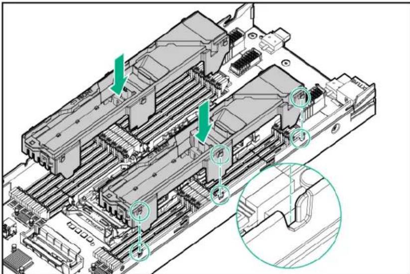
Installing the DIMM baffles
Procedure
- Install the DIMM baffles.
text_image
Technical diagram of a computer motherboard with labeled components and directional arrows indicating assembly or movement.- Install the access panel.
- Install the compute module.
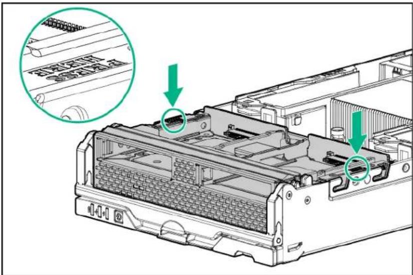
Installing the front panel/drive cage assembly
Procedure
- Install the front panel/drive cage assembly.
text_image
Technical diagram of a computer tower with highlighted internal components and green arrows indicating ports of interest.- Install all drives.
- Install the access panel.
- Install the compute module.
Setup
Installation overview
This section provides instructions for installing an HPE Synergy 480 Gen9 Compute Module in a frame for the first time.
Installation of a compute module requires the following steps:
Procedure
- Installing supported options in the compute module.
- Installing the compute module.
- Completing the compute module configuration.
Installing the compute module options
Before installing and initializing the compute module, install any compute module options, such as an additional processor, drive, or a mezzanine card.
Mezzanine options are classified as Type C and Type D mezzanine cards. The type of mezzanine card determines where the card can be installed in the compute module. Some mezzanine cards require that an interconnect module is installed in the associated ICM bay in the rear of the frame. Be sure to review the mezzanine card mapping information in the HPE Synergy Configuration and Compatibility Guide on the Hewlett Packard Enterprise website (http://www.hpe.com/info/synergy-docs).
For a list of supported options, see the product QuickSpecs on the Hewlett Packard Enterprise website (http://www.hpe.com/info/qs).
For compute module options installation information, see "Hardware options installation."
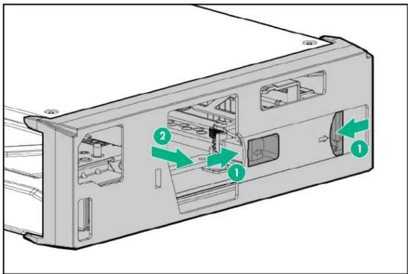
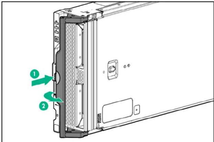
Installing the compute module
Procedure
- Verify that the device bay is configured for a half-height compute module. For more information, see the setup and installation guide for the frame on the Hewlett Packard Enterprise website.
- Remove the compute module end cap.
text_image
Technical diagram of a computer case with labeled components and directional arrows indicating movement or flow.- Prepare the compute module for installation by opening the compute module handle.
text_image
Technical diagram of a computer rear panel with labeled components and directional arrows indicating assembly or movement.- Install the compute module. Press the compute module handle near the release button to completely close the handle.
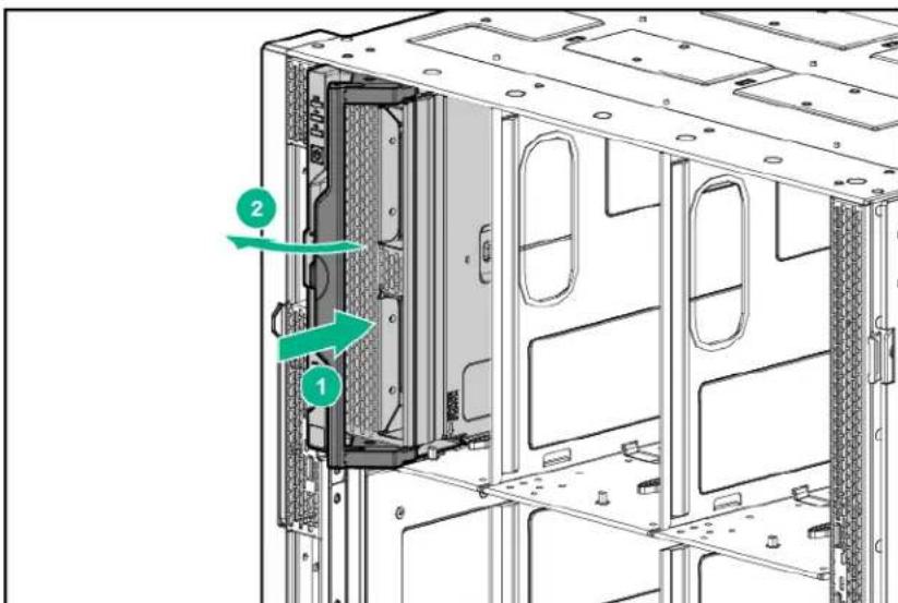
text_image
Technical diagram of a server rack with labeled components and directional arrows indicating movement or assembly.- Review the compute module front panel LEDs to determine the compute module status. For more information on the compute module LEDs, see "Component identification."
Completing the configuration
HPE OneView, hosted on the HPE Synergy Composer appliance installed within an HPE Synergy 12000 Frame, enables you to comprehensively manage a Synergy system throughout the hardware life cycle. To configure the compute module for the first time, log into HPE OneView from the frame. For more information, see the HPE Synergy 12000 Frame Setup and Installation Guide on the Hewlett Packard Enterprise website (www.hpe.com/info/synergy-docs).
When adding a compute module to an existing configuration, HPE OneView automatically detects the new hardware. Log into HPE OneView using your assigned user name and password to configure the hardware. See the HPE OneView User Guide on the Hewlett Packard Enterprise website (www.hpe.com/info/synergy-docs).
Hardware options installation
This chapter provides detailed instructions on how to install hardware options. For more information on supported options, see the product QuickSpecs on the Hewlett Packard Enterprise website (http://www.hpe.com/info/qs).
Introduction
If more than one option is being installed, read the installation instructions for all the hardware options and identify similar steps to streamline the installation process.

WARNING:
To reduce the risk of personal injury from hot surfaces, allow the drives and the internal system components to cool before touching them.

CAUTION:
To prevent damage to electrical components, properly ground the compute module before beginning any installation procedure. Improper grounding can cause electrostatic discharge.
Installing the drive option
The compute module supports up to two SFF SAS, NVMe, solid state, or SATA (supported only with the HPE Synergy 480 Gen9 compute module backplane) drives.

CAUTION:
To prevent improper cooling and thermal damage, do not operate the compute module or the enclosure unless all drive and device bays are populated with either a component or a blank.
To install the component:
Procedure
- Remove the drive blank.
- Prepare the drive:
• SAS, SATA, or solid state
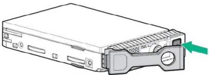
natural_image
Diagram of a computer drive showing internal components and a green arrow indicating a specific part (no text or symbols present)- NVMe—Press Do Not Remove to open the release handle.
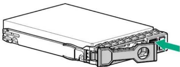
natural_image
Technical line drawing of a device chassis with connectors and a green arrow indicating a component (no text or symbols present)3. Install the drive:
• SAS, SATA, or solid state
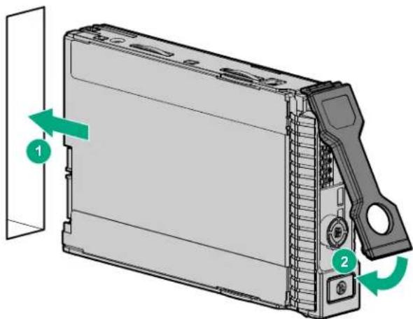
text_image
Diagram of a device with labeled components and directional arrows indicating movement or assembly• NVMe

text_image
Diagram of a server rack with labeled components and directional arrows indicating movement or change.- Determine the status of the drive from the drive LED definitions.
Installing the SFF flash adapter option

CAUTION:
To prevent improper cooling and thermal damage, do not operate the compute module or the enclosure unless all drive and device bays are populated with either a component or a blank.
Prequisites
The SFF flash adapter option is supported when any of the following components are installed:
• HPE Dynamic Smart Array B140i Controller
• HPE Smart Array P240nr Controller
• HPE H240nr Host Bus Adapter
• HPE Smart Array P542D Controller (with HPE Synergy 480 Gen9 compute module backplane installed)
To install the component:
Procedure
- Remove the drive blank.
- Install the uFF drives in the SFF flash adapter.
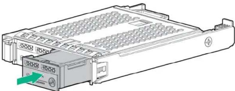
natural_image
Technical line drawing of a computer drive chassis with ports and control panel (no text or symbols)- Install the SFF flash adapter by pushing firmly near the left-side adapter ejection handle until the latching spring engages in the drive bay.
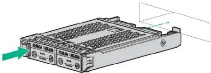
natural_image
Illustration of a rack-mounted electronic device with ventilation grilles and indicator lights (no text or symbols)Installing the controller option
For more information about supported options, see the product QuickSpecs on the Hewlett Packard Enterprise website.

CAUTION:
Hewlett Packard Enterprise recommends performing a complete backup of all compute module data before performing a controller or adapter installation or removal.

CAUTION:
In systems that use external data storage, be sure that the compute module is the first unit to be powered down and the last to be powered back up. Taking this precaution ensures that the system does not erroneously mark the drives as failed when the compute module is powered up.
To install the component:
Procedure
- Power down the compute module.
- Remove the compute module.
- Remove the access panel.
- Remove the front panel/drive cage assembly.
- Install the controller.
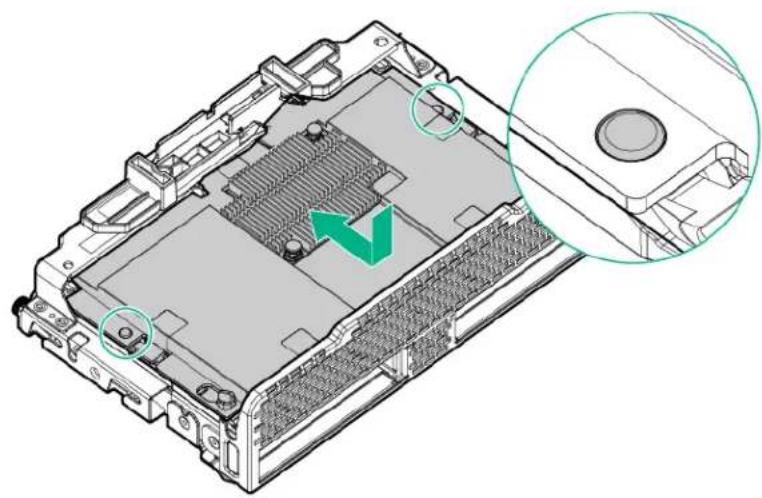
natural_image
Technical illustration of an internal hardware component with a green arrow indicating a specific area (no text or symbols present)- Install the front panel/drive cage assembly.
- Install the access panel.
- Install the compute module.
- Power up the compute module.
Installing the HPE Smart Storage Battery option
Procedure
- Power down the compute module.
- Remove the compute module.
- Place the compute module on a flat, level work surface.
- Remove the access panel.
- Remove the right DIMM baffle.
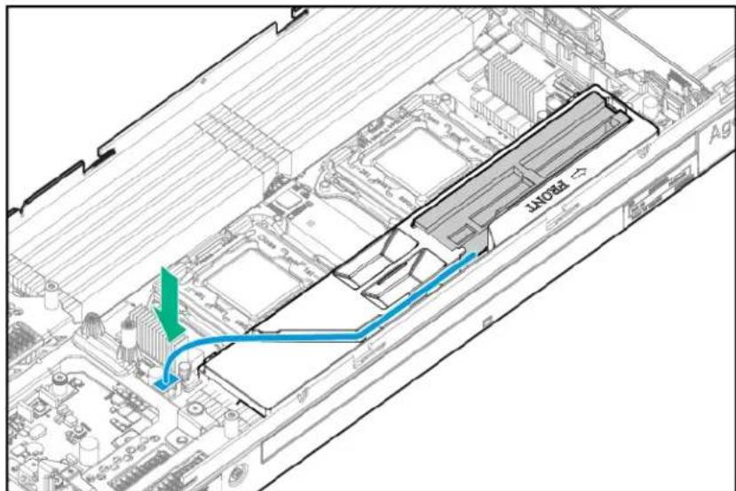
- Install the Smart Storage Battery.
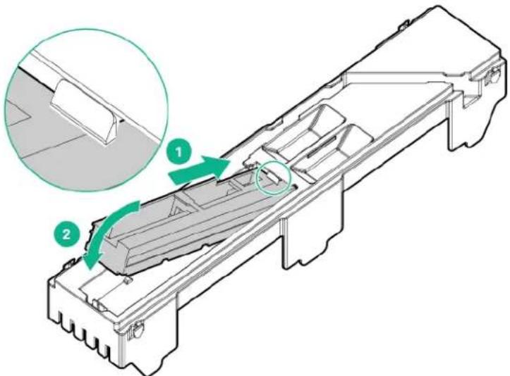
text_image
Technical diagram of a mechanical assembly with labeled components and an inset showing a detail view.-
Install the DIMM baffle.
-
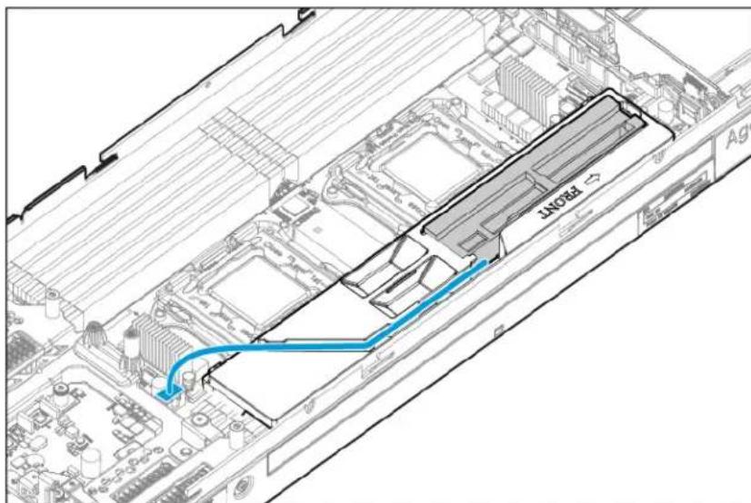
Connect the Smart Storage Battery to the system board. To locate the Smart Storage Battery connector, see the "System board components."
text_image
BEAUTY-
Install the access panel.
-
Install the compute module.
-
Power up the compute module.
Installing the mezzanine card options
IMPORTANT:
For more information about the association between the mezzanine bay and the interconnect bays, see the HPE Synergy 12000 Frame Setup and Installation Guide in the Hewlett Packard Enterprise Information Library. Where you install the mezzanine card determines where you need to install the interconnect modules.
To install the component:
Procedure
- Power down the compute module.
- Remove the compute module.
- Place the compute module on a flat, level work surface.
-
Remove the access panel.
-
Locate the appropriate mezzanine connector. To locate the connector, see the "System board components."
-
Remove the mezzanine connector cover, if installed.
-
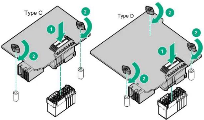
Install the mezzanine card. Press firmly on the PRESS HERE label above the mezzanine connector to seat the card.
When a GPU mezzanine adapter is installed in the compute module, an additional mounting bracket is required.
text_image
Type C 1 2 2 Type D 1 2 2- Install the access panel.
- Install the compute module.
- Power up the compute module.
Installing the HPE Smart Array P542D Controller mezzanine option
IMPORTANT:
For more information about the association between the mezzanine bay and the interconnect bays, see the HPE Synergy 12000 Frame Setup and Installation Guide in the Hewlett Packard Enterprise Information Library (http://www.hpe.com/info/synergy-docs). Where you install the mezzanine card determines where you need to install the interconnect modules.
To install the component:
Procedure
- Power down the compute module.
- Remove the compute module.
- Place the compute module on a flat, level work surface.
- Remove the access panel.
- Locate the appropriate mezzanine connector. To locate the connector, see System board components.
-
Remove the mezzanine connector cover, if installed.
-
Remove the front panel/drive cage assembly.
-
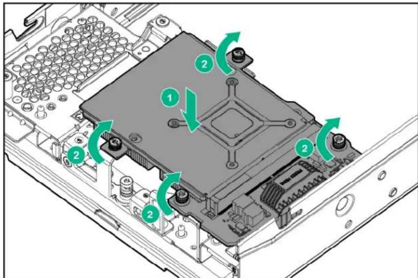
Install the mezzanine card. Press firmly on the PRESS HERE label above the mezzanine connector to seat the card.
text_image
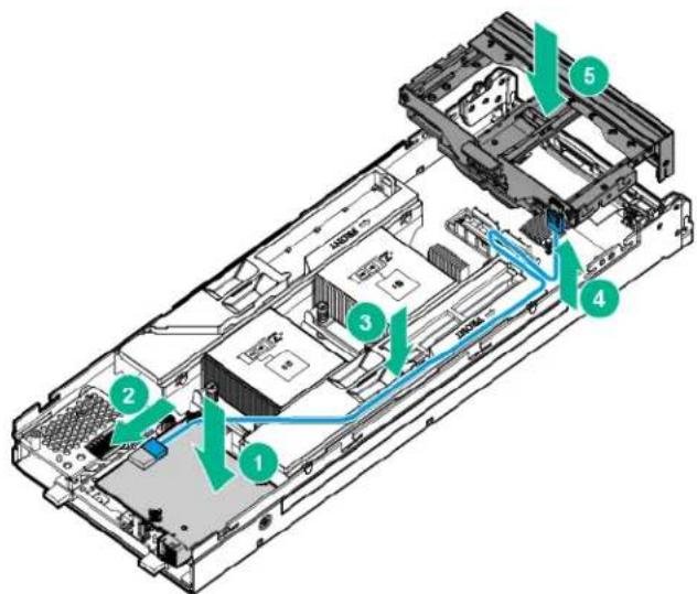
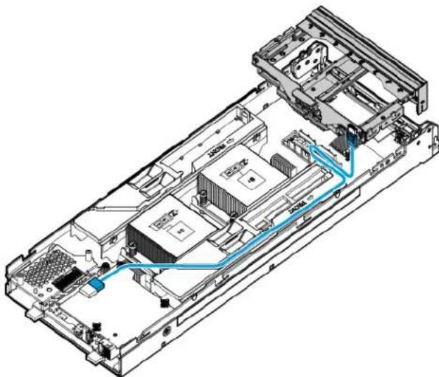
Technical diagram of an electronic device showing labeled components and green directional arrows indicating rotation or movement.- Install and route the HPE Smart Array P542D SAS cable from the premium backplane to the HPE Smart Array P542D Controller mezzanine card.
text_image
Technical diagram of an electronic device chassis with numbered components and directional arrows indicating flow or movement.- Install the access panel.
- Install the compute module.
- Power up the compute module.
Memory options
IMPORTANT:
This compute module does not support mixing LRDIMMs or RDIMMs. Attempting to mix any combination of these DIMMs can cause the compute module to halt during BIOS initialization.
The memory subsystem in this compute module can support LRDIMMs and RDIMMs:
- RDIMMs offer address parity protection.
- LRDIMMs support higher densities than single- and dual-rank RDIMMs, and higher speeds than quad-rank RDIMMs. This support enables you to install more high-capacity DIMMs, resulting in higher system capacities and higher bandwidth.
All types are referred to as DIMMs when the information applies to all types. When specified as LRDIMM or RDIMM, the information applies to that type only. All memory installed in the compute module must be the same type.
The compute module supports the following DIMM speeds:
- Single- and dual-rank PC4-2400 (DDR4-2400) RDIMMs operating at up to 2400 MT/s
- Dual- and quad-rank PC4-2400 (DDR4-2400) LRDIMMs operating at up to 2400 MT/s
Speed and capacity
| DIMM type DIMM rank DIMM capacity (GB) Native speed (MT/s) |
| RDIMM Single 8 2400 |
| RDIMM Single 16 2400 |
| RDIMM Dual 16 2400 |
| RDIMM Dual 32 2400 |
| LRDIMM Dual 32 2400 |
| LRDIMM Quad 64 2400 |
| LRDIMM Octal 128 2400 |
Depending on the processor model, the number of DIMMs installed, and whether LRDIMMs or RDIMMs are installed, the memory clock speed can reduce to 1600 MT/s.
Populated DIMM speed (MT/s)
| DIMM type DIMM rank 1 DIMM per | channel | 2 DIMMs per channel | 3 DIMMs per channel | |
| RDIMM | Single (8 GB) | 2400 | 2133 | 1866 |
| RDIMM | Single (16 GB) | 2400 | 2133 | 1866 |
| RDIMM | Dual (16 GB) | 2400 | 2400 | 1600 |
| RDIMM | Dual (32 GB) | 2400 | 2400 | 1600 |
| LRDIMM | Dual (32 GB) | 2400 | 2400 | 2133 |
| LRDIMM | Quad (64 GB) | 2400 | 2400 | 2133 |
| LRDIMM | Octal (128 GB) | 2400 | 2400 | 2133 |
SmartMemory
SmartMemory authenticates and unlocks certain features available only on Qualified memory and verifies whether installed memory has passed Hewlett Packard Enterprise qualification and test processes. Qualified memory is performance-tuned for ProLiant and BladeSystem servers and compute module, and provides future enhanced support through Active Health and manageability software.
Memory subsystem architecture
The memory subsystem in this compute module is divided into channels. Each processor supports four channels, and each channel supports three DIMM slots.
| Memory subsystem channel | Population order Slot number (Processor 1) | Slot number (Processor 2) |
| 1 A E I 12 11 10 1 2 3 | ||
| 2 B F J 9 8 7 4 5 6 | ||
| 3 C G K 1 2 3 12 11 10 | ||
| 4 D H L 4 5 6 9 8 7 |
For the location of the slot numbers, see "DIMM slot locations."
This multi-channel architecture provides enhanced performance in Advanced ECC mode. This architecture also enables Lockstep and Online Spare Memory modes.
DIMM slots in this server are identified by number and by letter. Letters identify the population order. Slot numbers indicate the DIMM slot ID for spare replacement.
DIMM ranks
To understand and configure memory protection modes properly, an understanding of DIMM rank is helpful. Some DIMM configuration requirements are based on these classifications.
A single-rank DIMM has one set of memory chips that is accessed while writing to or reading from the memory. A dual-rank DIMM is similar to having two single-rank DIMMs on the same module, with only one rank accessible at a time. A quad-rank DIMM is, effectively, two dual-rank DIMMs on the same module. Only one rank is accessible at a time. The compute module memory control subsystem selects the proper rank within the DIMM when writing to or reading from the DIMM.
Dual- and quad-rank DIMMs provide the greatest capacity with the existing memory technology. For example, if current DRAM technology supports 8-GB single-rank DIMMs, a dual-rank DIMM would be 16 GB, and a quad-rank DIMM would be 32 GB, and an octal-rank LR DIMM would be 64 GB.
LR DIMMs are labeled as quad- and octal-rank DIMMs. There are four and eight ranks of DRAM on the DIMM, but the LR DIMM buffer creates an abstraction that allows the DIMM to appear as a logical dual-rank DIMM to the system. This is called Rank Multiplication. The LR DIMM buffer also isolates the electrical loading of the DRAM from the system to allow for faster operation. These two changes allow the system to support up to three LR DIMMs per memory channel, providing for greater memory capacity and higher memory operating speed compared to quad-rank R DIMMs.
DIMM identification
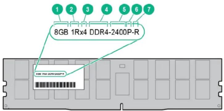
To determine DIMM characteristics, see the label attached to the DIMM and refer to the following illustration and table.
text_image
1 2 3 4 5 6 7 8GB 1Rx4 DDR4-2400P-R 8GB 1Rx4 DDR4-2400P-R| Item Description Definition | |
| 1 Capacity | 8 GB |
| 16 GB | |
| 32 GB | |
| 64 GB | |
| 128 GB | |
| 2 Rank | 1R = Single-rank |
| 2R = Dual-rank | |
| 4R = Quad-rank | |
| 8R = Octal-rank | |
| 3 Data width on DRAM | x4 = 4-bit |
| x8 = 8-bit | |
| 4 Memory generation DDR4 | |
| 5 Maximum memory speed 2400 MT/s | |
| 6 CAS latency | P=15 |
| T=17 | |
| 7 DIMM type | R = RDIMM (registered) |
| L = LRDIMM (load reduced) | |
For more information about product features, specifications, options, configurations, and compatibility, see the product QuickSpecs on the Hewlett Packard Enterprise website (http://www.hpe.com/info/qs).
Memory configurations
To optimize compute module availability, the compute module supports the following AMP modes:
- Advanced ECC—Provides up to 4-bit error correction and enhanced performance over Lockstep mode. This mode is the default option for this compute module.
- Online spare memory—Provides protection against failing or degraded DIMMs. Certain memory is reserved as spare, and automatic failover to spare memory occurs when the system detects a DIMM that is degrading. This allows DIMMs that have a higher probability of receiving an uncorrectable memory error (which would result in system downtime) to be removed from operation.
Advanced Memory Protection options are configured in the BIOS/Platform Configuration (RBSU). If the requested AMP mode is not supported by the installed DIMM configuration, the compute module boots in Advanced ECC mode. For more information, see the HPE UEFI System Utilities User Guide for ProLiant Gen9 Servers on the Hewlett Packard Enterprise website.
Maximum capacity
| DIMM type DIMM rank Capacity (GB) One processor | (GB) | Two processors (GB) | |
| RDIMM Single 8 96 192 | |||
| RDIMM Single 16 192 | 384 | ||
Table Continued
| DIMM type DIMM rank Capacity (GB) One processor | (GB) | Two processors (GB) |
| RDIMM Dual 16 192 384 | ||
| RDIMM Dual 32 384 768 | ||
| LRDIMM Dual 32 384 768 | ||
| LRDIMM Quad 64 768 1536 | ||
| LRDIMM Octal 128 1536 3072 |
For the latest memory configuration information, see the QuickSpecs on the Hewlett Packard Enterprise website (http://www.hpe.com/info/qs).
Advanced ECC memory configuration
Advanced ECC memory is the default memory protection mode for this compute module. Standard ECC can correct single-bit memory errors and detect multi-bit memory errors. When multi-bit errors are detected using Standard ECC, the error is signaled to the compute module and causes the compute module to halt.
Advanced ECC protects the compute module against some multi-bit memory errors. Advanced ECC can correct both single-bit memory errors and 4-bit memory errors if all failed bits are on the same DRAM device on the DIMM.
Advanced ECC provides additional protection over Standard ECC because it is possible to correct certain memory errors that would otherwise be uncorrected and result in a compute module failure. Using HPE Advanced Memory Error Detection technology, the compute module provides notification when a DIMM is degrading and has a higher probability of uncorrectable memory error.
Online Spare memory configuration
Online spare memory provides protection against degraded DIMMs by reducing the likelihood of uncorrected memory errors. This protection is available without any operating system support.
Online spare memory protection dedicates one rank of each memory channel for use as spare memory. The remaining ranks are available for OS and application use. If correctable memory errors occur at a rate higher than a specific threshold on any of the non-spare ranks, the compute module automatically copies the memory contents of the degraded rank to the online spare rank. The compute module then deactivates the failing rank and automatically switches over to the online spare rank.
General DIMM slot population guidelines
Observe the following guidelines for all AMP modes:
- Install DIMMs only if the corresponding processor is installed.
- When two processors are installed, balance the DIMMs across the two processors.
- White DIMM slots denote the first slot of a channel (Ch 1-A, Ch 2-B, Ch 3-C, Ch 4-D)
- Do not mix RDIMMs and LRDIMMs.
- When one processor is installed, install DIMMs in sequential alphabetic order: A, B, C, D, E, F, and so forth.
- When two processors are installed, install the DIMMs in sequential alphabetic order balanced between the two processors: P1-A, P2-A, P1-B, P2-B, P1-C, P2-C, and so forth.
- When single-rank, dual-rank, and quad-rank DIMMs are populated for two DIMMs per channel or three DIMMs per channel, always populate the higher number rank DIMM first (starting from the farthest slot). For example, first quad-rank DIMM, then dual-rank DIMM, and then lastly single-rank DIMM.
- DIMMs should be populated starting farthest from the processor on each channel.
- For DIMM spare replacement, install the DIMMs per slot number as instructed by the system software.
For more information about compute module memory, see http://www.hpe.com/info/memory.
DIMM speeds are supported as indicated in the following table.
| Populated slots (per channel) | Rank DIMM Speeds supported | (MT/s) |
| 1 Single, dual, or quad RDIMM or LRDIMM 2400 | ||
| 2 Single RDIMM 2133 | ||
| 2 Dual or quad RDIMM or LRDIMM 2400 | ||
| 3 Single RDIMM 1866 | ||
| 3 Dual RDIMM 1600 | ||
| 3 Dual or quad LRDIMM 2133 | ||
Advanced ECC population guidelines
For Advanced ECC mode configurations, observe the following guidelines:
- Observe the general DIMM slot population guidelines.
• DIMMs may be installed individually.
Online spare population guidelines
For Online Spare memory mode configurations, observe the following guidelines:
- Observe the general DIMM slot population guidelines.
• Each channel must have a valid online spare configuration. - Each channel can have a different valid online spare configuration.
• Each populated channel must have a spare rank. A single dual-rank DIMM is not a valid configuration.
Population order
For memory configurations with a single processor or multiple processors, DIMMs must be populated sequentially in alphabetical order (A through L).
After installing the DIMMs, use the BIOS/Platform Configuration (RBSU) in the UEFI System Utilities to configure supported AMP modes.
Installing a DIMM

CAUTION:
To avoid damage to the hard drives, memory, and other system components, the air baffle, drive blanks, and access panel must be installed when the compute module is powered up.

CAUTION:
To avoid damage to the hard drives, memory, and other system components, be sure to install the correct DIMM baffles for your compute module model.
To install the component:
Procedure
- Power down the compute module.
- Remove the compute module.
-
Place the compute module on a flat, level work surface.
-
Remove the access panel.
- Remove the DIMM baffle.
- Install the DIMM.
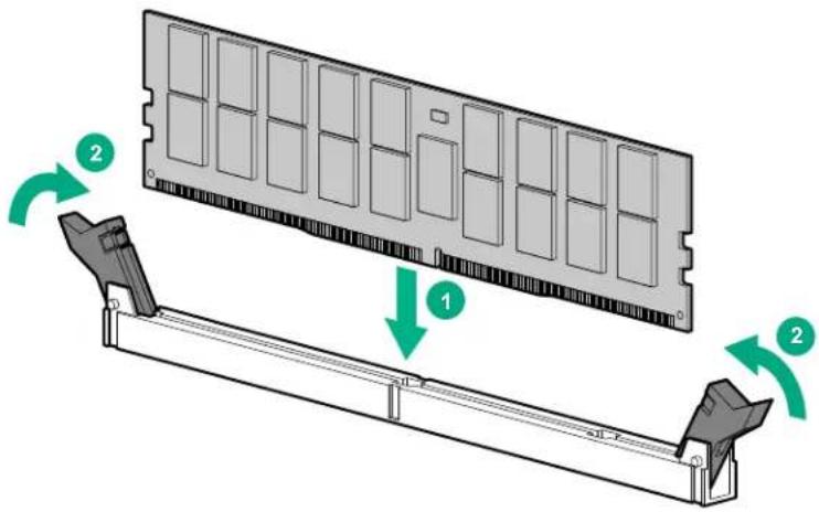
text_image
Diagram showing a computer RAM module with two labeled components and directional arrows indicating rotation or movement.- Install all DIMM baffles.
- Install the access panellinstall the access panel.
- Install the compute module.
- Power up the compute module.
To configure the memory mode, use UEFI System Utilities.
Installing the processor option

WARNING:
To reduce the risk of personal injury from hot surfaces, allow the drives and the internal system components to cool before touching them.

CAUTION:
To prevent possible compute module malfunction and damage to the equipment, multiprocessor configurations must contain processors with the same part number.

CAUTION:
The heatsink thermal interface media is not reusable and must be replaced if the heatsink is removed from the processor after it has been installed.

CAUTION:
To prevent possible compute module overheating, always populate processor socket 2 with a processor and a heatsink or a processor socket cover and a heatsink blank.

CAUTION:
To prevent damage to electrical components, properly ground the compute module before beginning any installation procedure. Improper grounding can cause ESD.

IMPORTANT:
Processor socket 1 must be populated at all times or the compute module does not function.
To install the processor:
Procedure
- Update the system ROM.
Locate and download the latest ROM version from the Hewlett Packard Enterprise website at http://www.hpe.com/support. Follow the instructions on the website to update the system ROM.
- Power down the compute module.
- Remove the compute module.
- Remove the access panel.
- Remove all DIMM baffles.
- Remove the heatsink blank. Retain the heatsink blank for future use.
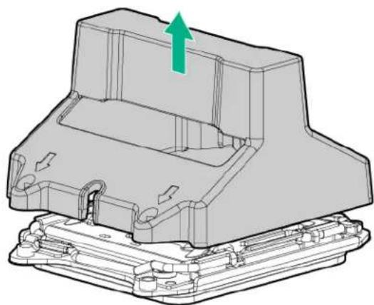
natural_image
3D mechanical component diagram showing a housing with a green arrow indicating upward motion (no text or symbols)- Open each of the processor locking levers in the order indicated in the following illustration, and then open the processor retaining bracket.
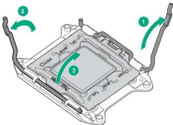
text_image
Close Level 1st 3 2 1- Remove the clear processor socket cover. Retain the processor socket cover for future use.
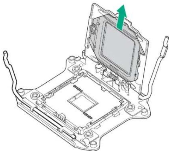
natural_image
Technical line drawing of an electronic component with a green arrow indicating a specific part (no text or symbols present)
CAUTION:
THE PINS ON THE SYSTEM BOARD ARE VERY FRAGILE AND EASILY DAMAGED. To avoid damage to the system board, do not touch the processor or the processor socket contacts.
- Install the processor. Verify that the processor is fully seated in the processor retaining bracket by visually inspecting the processor installation guides on either side of the processor. THE PINS ON THE SYSTEM BOARD ARE VERY FRAGILE AND EASILY DAMAGED.
Install the processor. Verify that the processor is fully seated in the processor retaining bracket by visually inspecting the processor installation guides on either side of the processor.
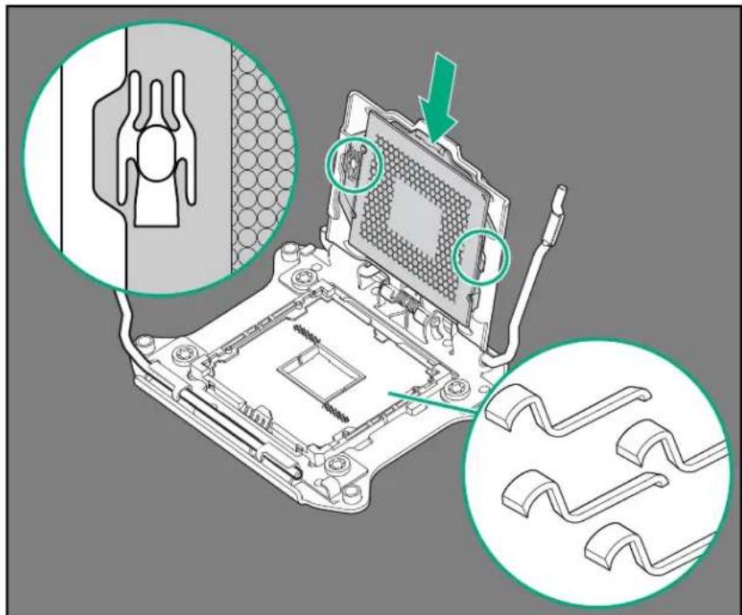
text_image
Technical diagram showing a computer motherboard with labeled components and annotations in Chinese- Close the processor retaining bracket. When the processor is installed properly inside the processor retaining bracket, the processor retaining bracket clears the flange on the front of the socket.
A CAUTION:
Do not press down on the processor. Pressing down on the processor might damage the processor socket and the system board. Press only in the area indicated on the processor retaining bracket.
CAUTION:
Close and hold down the processor cover socket while closing the processor locking levers. The levers should close without resistance. Forcing the levers closed can damage the processor and socket, requiring system board replacement.
- Press and hold the processor retaining bracket in place, and then close each processor locking lever. Press only in the area indicated on the processor retaining bracket.
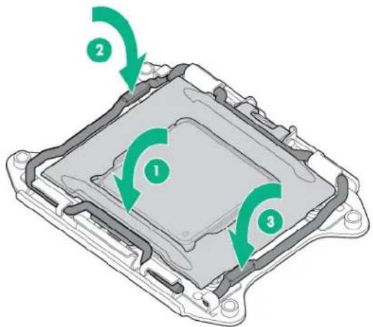
text_image
Diagram of a mechanical component with three green arrows indicating rotational or directional changes, labeled 1, 2, and 3.- Remove the thermal interface protective cover from the heatsink.
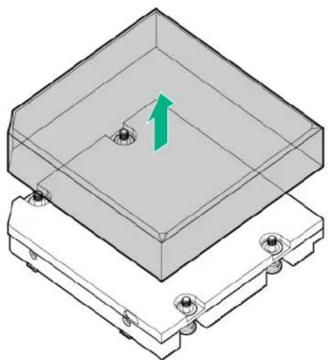
natural_image
3D diagram of a mechanical housing with a green arrow indicating upward motion, no text or symbols presentA CAUTION:
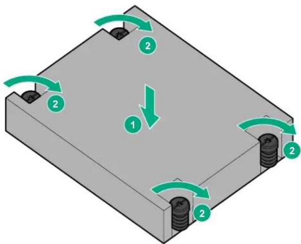
CAUTION: To avoid damage to the system board, processor socket, and screws, do not overtighten the heatsink screws.
- Install the heatsink. A T-15 screwdriver is required to install the heatsink.
text_image
Diagram showing a mechanical assembly with labeled components and directional arrows indicating motion or force directions.- Install all DIMM baffles.
- Install the access panel.
- Install the compute module.
HP Trusted Platform Module option
When installing or replacing TPM, observe the following guidelines:
- Do not remove an installed TPM. Once installed, the TPM becomes a permanent part of the system board.
- When installing or replacing hardware, Hewlett Packard Enterprise service providers cannot enable the TPM or the encryption technology. For security reasons, only the customer can enable these features.
- When returning a system board for service replacement, do not remove the TPM from the system board. When requested, Hewlett Packard Enterprise Service provides a TPM with the spare system board.
- Any attempt to remove an installed TPM from the system board breaks or disfigures the TPM security rivet. Upon locating a broken or disfigured rivet on an installed TPM, administrators should consider the system compromised and take appropriate measures to ensure the integrity of the system data.
- When using BitLocker, always retain the recovery key/password. The recovery key/password is required to enter Recovery Mode after BitLocker detects a possible compromise of system integrity.
- Hewlett Packard Enterprise is not liable for blocked data access caused by improper TPM use. For operating instructions, see the encryption technology feature documentation provided by the operating system.
For more information about product features, specifications, options, configurations, and compatibility, see the product QuickSpecs on the Hewlett Packard Enterprise website.
Use these instructions to install and enable a TPM on a supported compute module. This procedure includes three sections:
- Installing the Trusted Platform Module board.
- Retaining the recovery key/password.
- Enabling the Trusted Platform Module.
Enabling the TPM requires accessing BIOS/Platform Configuration (RBSU) in the UEFI System Utilities.
TPM installation requires the use of drive encryption technology, such as the Microsoft Windows BitLocker Drive Encryption feature. For more information on BitLocker, see the Microsoft website.

CAUTION:
Always observe the guidelines in this document. Failure to follow these guidelines can cause hardware damage or halt data access.
Installing the Trusted Platform Module board

WARNING:
To reduce the risk of personal injury from hot surfaces, allow the drives and the internal system components to cool before touching them.
To install the component:
Procedure
- Power down the compute module.
- Remove the compute module.
- Place the compute module on a flat, level work surface.
- Remove the access panel.
- Remove all drives.
- Remove all drive blanks.
- Remove all DIMM baffles.
- Remove the front panel/drive cage assembly.
- Locate the TPM connector.

CAUTION:
Any attempt to remove an installed TPM from the system board breaks or disfigures the TPM security rivet. Upon locating a broken or disfigured rivet on an installed TPM, administrators should consider the system compromised and take appropriate measures to ensure the integrity of the system data.
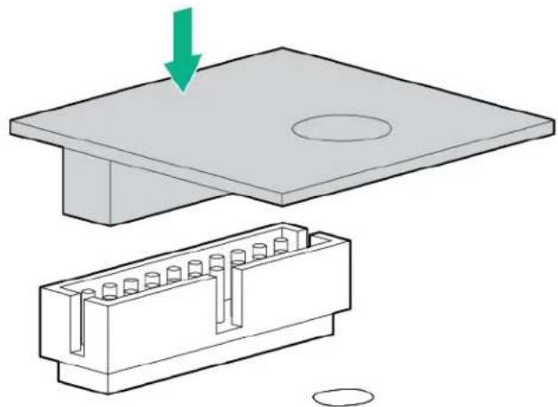
- Install the TPM board. Press down on the connector to seat the board (System board components).
natural_image
Technical illustration of a mechanical assembly showing a component being lowered into a housing, with no visible text or symbols.- Install the TPM security rivet by pressing the rivet firmly into the system board.

text_image
Diagram showing a mechanical press or stamping setup with labeled components and directional arrows indicating movement or force.- Install the front panel/drive cage assembly.
- Install all drives.
- Install the DIMM baffles.
- Install the access panel.
- Install the compute module.
- Power up the compute module.
Retaining the recovery key/password
The recovery key/password is generated during BitLocker setup, and can be saved and printed after BitLocker is enabled. When using BitLocker, always retain the recovery key/password. The recovery key/password is required to enter Recovery Mode after BitLocker detects a possible compromise of system integrity.
To help ensure maximum security, observe the following guidelines when retaining the recovery key/password:
• Always store the recovery key/password in multiple locations.
• Always store copies of the recovery key/password away from the compute module.
- Do not save the recovery key/password on the encrypted hard drive.
Enabling the Trusted Platform Module

CAUTION:
When a TPM is installed and enabled on the compute module, data access is locked if you fail to follow the proper procedures for updating the system or option firmware, replacing the system board, replacing a hard drive, or modifying OS application TPM settings.
Procedure
- During the server startup sequence, press the F9 key to access System Utilities.
- From the System Utilities screen, select System Configuration > BIOS/Platform Configuration (RBSU) > Server Security.
- Select Trusted Platform Module Options, and press the Enter key.
-
To set the TPM operational state:
-
If TPM 1.2 is installed, then select No Action, Enable, Disable, or Clear.
-
If TPM 2.0 is installed, then select No Action or Clear.
-
Select Visible to set the TPM Visibility, if necessary.
- Press the F10 key to save your selection.
- When prompted to save the change in System Utilities, press the Y key.
- Press the ESC key to exit System Utilities. Then, press the Enter key when prompted to reboot the compute module.
The compute module then reboots a second time without user input. During this reboot, the TPM setting becomes effective.
- Enable TPM functionality in the OS, such as Microsoft Windows BitLocker or measured boot.
For more information on adjusting TPM usage in BitLocker, see the Microsoft website.
For more information on the UEFI System Utilities, see the UEFI System Utilities User Guide for HPE ProLiant Gen9 and Synergy Servers in the UEFI Information Library.
Cabling
Cabling resources
Cabling configurations and requirements vary depending on the product and installed options. For more information about product features, specifications, options, configurations, and compatibility, see the product QuickSpecs on the Hewlett Packard Enterprise website.
HPE Smart Storage Battery cabling
text_image
RONT A9HPE Smart Array P542D Controller cabling
natural_image
Technical line drawing of an electronic device chassis with internal components and blue flow paths (no text or symbols)Software and configuration utilities
Management and diagnostic tools
For more information, see the HPE Synergy Configuration and Compatibility Guide on the Hewlett Packard Enterprise website.
Removing and replacing the system battery
If the compute module no longer automatically displays the correct date and time, then replace the battery that provides power to the real-time clock. Under normal use, battery life is 5 to 10 years.

WARNING:
The computer contains an internal lithium manganese dioxide, a vanadium pentoxide, or an alkaline battery pack. A risk of fire and burns exists if the battery pack is not properly handled. To reduce the risk of personal injury:
- Do not attempt to recharge the battery.
- Do not expose the battery to temperatures higher than 60^ (140°F).
- Do not disassemble, crush, puncture, short external contacts, or dispose of in fire or water.
- Replace only with the spare designated for this product.
To remove the component:
- Power down the compute module (Powering down the compute module).
- Remove the compute module (Removing the compute module).
- Place the compute module on a flat, level work surface.
- Remove the access panel (Removing the access panel).
- Remove the front panel/drive cage assembly (Removing the front panel/drive cage assembly).
- Locate the battery on the system board (System board components).
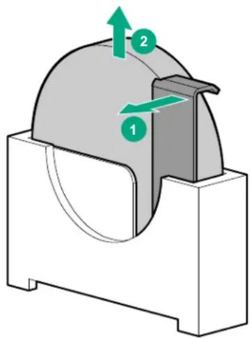
- Remove the battery.
text_image
Technical diagram showing a mechanical component with labeled parts 1 and 2, indicating directional movement or force vectors.
IMPORTANT:
Replacing the system board battery resets the system ROM to its default configuration. After replacing the battery, use BIOS/Platform Configuration (RBSU) in the UEFI System Utilities to reconfigure the system.
To replace the component, reverse the removal procedure.
For more information about battery replacement or proper disposal, contact an authorized reseller or an authorized service provider.
Warranty and regulatory information
Warranty information
HPE ProLiant and x86 Servers and Options
HPE Enterprise Servers
HPE Storage Products
HPE Networking Products
Regulatory information
Safety and regulatory compliance
For important safety, environmental, and regulatory information, see Safety and Compliance Information for Server, Storage, Power, Networking, and Rack Products, available at the Hewlett Packard Enterprise website.
Belarus Kazakhstan Russia marking

Manufacturer and Local Representative Information
Manufacturer information:
Hewlett Packard Enterprise Company, 3000 Hanover Street, Palo Alto, CA 94304 U.S.
Local representative information Russian:
- Russia:
Local representative information Kazakh:
- Russia:
The manufacturing date is defined by the serial number.
CCSYWWZZZZ (serial number format for this product)
Valid date formats include:
- YWW, where Y indicates the year counting from within each new decade, with 2000 as the starting point; for example, 238: 2 for 2002 and 38 for the week of September 9. In addition, 2010 is indicated by 0, 2011 by 1, 2012 by 2, 2013 by 3, and so forth.
- YYWW, where YY indicates the year, using a base year of 2000; for example, 0238: 02 for 2002 and 38 for the week of September 9.
Turkey RoHS material content declaration
Ukraine RoHS material content declaration
To prevent damaging the system, be aware of the precautions you must follow when setting up the system or handling parts. A discharge of static electricity from a finger or other conductor may damage system boards or other static-sensitive devices. This type of damage may reduce the life expectancy of the device.
To prevent electrostatic damage:
- Avoid hand contact by transporting and storing products in static-safe containers.
- Keep electrostatic-sensitive parts in their containers until they arrive at static-free workstations.
- Place parts on a grounded surface before removing them from their containers.
- Avoid touching pins, leads, or circuitry.
- Always be properly grounded when touching a static-sensitive component or assembly.
Grounding methods to prevent electrostatic discharge
Several methods are used for grounding. Use one or more of the following methods when handling or installing electrostatic-sensitive parts:
- Use a wrist strap connected by a ground cord to a grounded workstation or computer chassis. Wrist straps are flexible straps with a minimum of 1 megohm ±10 percent resistance in the ground cords. To provide proper ground, wear the strap snug against the skin.
- Use heel straps, toe straps, or boot straps at standing workstations. Wear the straps on both feet when standing on conductive floors or dissipating floor mats.
- Use conductive field service tools.
- Use a portable field service kit with a folding static-dissipating work mat.
If you do not have any of the suggested equipment for proper grounding, have an authorized reseller install the part.
For more information on static electricity or assistance with product installation, contact an authorized reseller.
Specifications
Environmental specifications
| Specification Value |
| Temperature range* — |
| Operating 10°C to 35°C (50°F to 95°F) |
| Non-operating -30°C to 60°C (-22°F to 140°F) |
| Relative humidity (noncondensing)** — |
| Operating 10% to 90% @ 28°C (82.4°F) |
| Non-operating 5% to 95% @ 38.7°C (101.7°F) |
| Altitude† — |
| Operating 3050 m (10,000 ft) |
| Non-operating 9144 m (30,000 ft) |
* The following temperature conditions and limitations apply:
- All temperature ratings shown are for sea level.
- An altitude derating of 1^ per 304.8 m (1.8°F per 1,000 ft) up to 3048 m (10,000 ft) applies.
- No direct sunlight is allowed.
- The maximum permissible rate of change is 10^ / hr (18°F/hr).
- The type and number of options installed might reduce the upper temperature and humidity limits.
- Operating with a fan fault or above 30^ (86°F) might reduce system performance.
** Storage maximum humidity of 95% is based on a maximum temperature of 45°C (113°F).
† Maximum storage altitude corresponds to a minimum pressure of 70 kPa (10.1 psia).
Compute module specifications
| Specification Value |
| Height 63.50 mm (2.50 in) |
| Depth 600.00 mm (23.62 in) |
| Width 214.00 mm (8.43 in) |
| Weight (maximum) 8.16 kg (18.00 lb) |
| Weight (minimum) 6.57 kg (14.50 lb) |
Documentation and troubleshooting resources for HPE Synergy
HPE Synergy documentation
The Hewlett Packard Enterprise Information Library (www.hpe.com/info/synergy-docs) is a task-based repository. It includes installation instructions, user guides, maintenance and service guides, best practices, and links to additional resources. Use this website to obtain the latest documentation, including:
- Learning about HPE Synergy technology
- Installing and cabling HPE Synergy
- Updating the HPE Synergy components
• Using and managing HPE Synergy
• Troubleshooting HPE Synergy
HPE Synergy Configuration and Compatibility Guide
The HPE Synergy Configuration and Compatibility Guide is in the Hewlett Packard Enterprise Information Library (www.hpe.com/info/synergy-docs). It provides an overview of HPE Synergy management and fabric architecture, detailed hardware component identification and configuration, and cabling examples.
HPE OneView User Guide for HPE Synergy
The HPE OneView User Guide for HPE Synergy is in the Hewlett Packard Enterprise Information Library (www.hpe.com/info/synergy-docs). It describes resource features, planning tasks, configuration quick start tasks, navigational tools for the graphical user interface, and more support and reference information for HPE OneView.
HPE OneView Global Dashboard
The HPE OneView Global Dashboard provides a unified view of health, alerting, and key resources managed by HPE OneView across multiple platforms and data center sites. The HPE OneView Global Dashboard User Guide is in the Hewlett Packard Enterprise Information Library (www.hpe.com/info/synergy-docs). It provides instructions for installing, configuring, navigating, and troubleshooting the HPE OneView Global Dashboard.
HPE Synergy Image Streamer User Guide
The HPE Synergy Image Streamer User Guide is in the Hewlett Packard Enterprise Information Library (www.hpe.com/info/synergy-docs). It describes the OS deployment process using Image Streamer, features of Image Streamer, and purpose and life cycle of Image Streamer artifacts. It also includes authentication, authorization, and troubleshooting information for Image Streamer.
HPE Synergy Image Streamer GitHub
The HPE Synergy Image Streamer GitHub repository (github.com/HewlettPackard) contains sample artifacts and documentation on how to use the sample artifacts. It also contains technical white papers explaining deployment steps that can be performed using Image Streamer.
HPE Synergy Software Overview Guide
The HPE Synergy Software Overview Guide is in the Hewlett Packard Enterprise Information Library (www.hpe.com/info/synergy-docs). It provides detailed references and overviews of the various software
and configuration utilities to support HPE Synergy. The guide is task-based and covers the documentation and resources for all supported software and configuration utilities available for:
• HPE Synergy setup and configuration
- OS deployment
- Firmware updates
- Troubleshooting
- Remote support
Best Practices for HPE Synergy Firmware and Driver Updates
The Best Practices for HPE Synergy Firmware and Driver Updates is in the Hewlett Packard Enterprise Information Library (www.hpe.com/info/synergy-docs). It provides information on recommended best practices to update firmware and drivers through HPE Synergy Composer, which is powered by HPE OneView.
HPE OneView Support Matrix for HPE Synergy
The HPE OneView Support Matrix for HPE Synergy is in the Hewlett Packard Enterprise Information Library (www.hpe.com/info/synergy-docs). It maintains the latest software and firmware requirements, supported hardware, and configuration maximums for HPE OneView.
HPE Synergy Image Streamer Support Matrix
The HPE Synergy Image Streamer Support Matrix is in the Hewlett Packard Enterprise Information Library (www.hpe.com/info/synergy-docs). It maintains the latest software and firmware requirements, supported hardware, and configuration maximums for HPE Synergy Image Streamer.
HPE Synergy Glossary
The HPE Synergy Glossary, in the Hewlett Packard Enterprise Information Library (www.hpe.com/info/synergy-docs), defines common terminology associated with HPE Synergy.
HPE Synergy troubleshooting resources
HPE Synergy troubleshooting resources are available within HPE OneView and in the Hewlett Packard Enterprise Information Library (www.hpe.com/info/synergy-docs).
Troubleshooting within HPE OneView
HPE OneView graphical user interface includes alert notifications and options for troubleshooting within HPE OneView. The UI provides multiple views of HPE Synergy components, including colored icons to indicate resource status and potential problem resolution in messages.
You can also use the Enclosure view and Map view to quickly see the status of all discovered HPE Synergy hardware.
HPE Synergy Troubleshooting Guide
The HPE Synergy Troubleshooting Guide is in the Hewlett Packard Enterprise Information Library (www.hpe.com/info/synergy-docs). It provides information for resolving common problems and courses of action for fault isolation and identification, issue resolution, and maintenance for both HPE Synergy hardware and software components.
HPE Error Message Guide for HPE Synergy
The HPE Error Message Guide for HPE Synergy is in the Hewlett Packard Enterprise Information Library (www.hpe.com/info/synergy-docs). It provides information for resolving common problems associated with specific error messages received for both HPE Synergy hardware and software components.
HPE OneView and HPE OneView REST API scripting help
The HPE OneView Help, the HPE OneView REST API Scripting Help, and the HPE OneView API Reference are readily accessible, embedded online help available within the HPE OneView user interface. These help files include “Learn more” links to common issues, as well as procedures and examples to troubleshoot issues within HPE Synergy.
The help files are also available in the Hewlett Packard Enterprise Information Library (www.hpe.com/info/synergy-docs).
HPE Synergy QuickSpecs
HPE Synergy has system specifications as well as individual product and component specifications. For complete specification information, see the HPE Synergy and individual Synergy product QuickSpecs on the Hewlett Packard Enterprise website (www.hpe.com/info/qs).
Support and other resources
Accessing Hewlett Packard Enterprise Support
- For live assistance, go to the Contact Hewlett Packard Enterprise Worldwide website.
- To access documentation and support services, go to the Hewlett Packard Enterprise Support Center website.
Information to collect
- Technical support registration number (if applicable)
- Product name, model or version, and serial number
- Operating system name and version
- Firmware version
- Error messages
• Product-specific reports and logs - Add-on products or components
• Third-party products or components
Accessing updates
- Some software products provide a mechanism for accessing software updates through the product interface. Review your product documentation to identify the recommended software update method.
- To download product updates, go to either of the following:
• Hewlett Packard Enterprise Support Center Get connected with updates page - Software Depot website
• To view and update your entitlements, and to link your contracts and warranties with your profile, go to the Hewlett Packard Enterprise Support Center More Information on Access to Support Materials page.
IMPORTANT:
: Access to some updates might require product entitlement when accessed through the Hewlett Packard Enterprise Support Center. You must have an HP Passport set up with relevant entitlements.
Websites
• Hewlett Packard Enterprise Information Library
• Hewlett Packard Enterprise Support Center
- Contact Hewlett Packard Enterprise Worldwide
- Subscription Service/Support Alerts
- Software Depot
- Customer Self Repair
• Insight Remote Support
• Serviceguard Solutions for HP-UX
- Single Point of Connectivity Knowledge (SPOCK) Storage compatibility matrix
• Storage white papers and analyst reports
Customer Self Repair
Hewlett Packard Enterprise products are designed with many Customer Self Repair (CSR) parts to minimize repair time and allow for greater flexibility in performing defective parts replacement. If during the diagnosis period Hewlett Packard Enterprise (or Hewlett Packard Enterprise service providers or service partners) identifies that the repair can be accomplished by the use of a CSR part, Hewlett Packard Enterprise will ship that part directly to you for replacement. There are two categories of CSR parts:
- Mandatory—Parts for which customer self repair is mandatory. If you request Hewlett Packard Enterprise to replace these parts, you will be charged for the travel and labor costs of this service.
- Optional—Parts for which customer self repair is optional. These parts are also designed for customer self repair. If, however, you require that Hewlett Packard Enterprise replace them for you, there may or may not be additional charges, depending on the type of warranty service designated for your product.
NOTE: Some Hewlett Packard Enterprise parts are not designed for customer self repair. In order to satisfy the customer warranty, Hewlett Packard Enterprise requires that an authorized service provider replace the part. These parts are identified as "No" in the Illustrated Parts Catalog.
Based on availability and where geography permits, CSR parts will be shipped for next business day delivery. Same day or four-hour delivery may be offered at an additional charge where geography permits. If assistance is required, you can call the Hewlett Packard Enterprise Support Center and a technician will help you over the telephone. Hewlett Packard Enterprise specifies in the materials shipped with a replacement CSR part whether a defective part must be returned to Hewlett Packard Enterprise. In cases where it is required to return the defective part to Hewlett Packard Enterprise, you must ship the defective part back to Hewlett Packard Enterprise within a defined period of time, normally five (5) business days. The defective part must be returned with the associated documentation in the provided shipping material. Failure to return the defective part may result in Hewlett Packard Enterprise billing you for the replacement. With a customer self repair, Hewlett Packard Enterprise will pay all shipping and part return costs and determine the courier/carrier to be used.
For more information about the Hewlett Packard Enterprise CSR program, contact your local service provider. For the North American program, go to the Hewlett Packard Enterprise CSR website.
Customer Self Repair
Customer Self Repair
Remote support is available with supported devices as part of your warranty or contractual support agreement. It provides intelligent event diagnosis, and automatic, secure submission of hardware event notifications to Hewlett Packard Enterprise, which will initiate a fast and accurate resolution based on your product's service level. Hewlett Packard Enterprise strongly recommends that you register your device for remote support.
If your product includes additional remote support details, use search to locate that information.
Remote support and Proactive Care information
HPE Get Connected
HPE Proactive Care services
HPE Proactive Care service: Supported products list
HPE Proactive Care advanced service: Supported products list
Proactive Care customer information
Proactive Care central
Proactive Care service activation
Acronyms and abbreviations
AMP
Advanced Memory Protection
API
application program interface
ASR
Automatic Server Recovery
CSR
certificate signing request
HP SUM
HP Smart Update Manager
HPE SSA
HPE Smart Storage Administrator
iLO
Integrated Lights-Out
IML
Integrated Management Log
JSON
JavaScript Object Notation
KVM
keyboard, video, and mouse
PCIe
Peripheral Component Interconnect Express
POST
Power-On Self-Test
RBSU
ROM-Based Setup Utility
REST
representational state transfer
SAS
serial attached SCSI
SPP
Service Pack for ProLiant
SUV
serial, USB, video
TPM
Trusted Platform Module
UEFI
Unified Extensible Firmware Interface
USB
universal serial bus
VCA
Version Control Agent
VCRM
Version Control Repository Manager
Documentation feedback
Hewlett Packard Enterprise is committed to providing documentation that meets your needs. To help us improve the documentation, send any errors, suggestions, or comments to Documentation Feedback (docsfeedback@hpe.com). When submitting your feedback, include the document title, part number, edition, and publication date located on the front cover of the document. For online help content, include the product name, product version, help edition, and publication date located on the legal notices page.