
ProCurve 2800 - Switch HP - Free user manual and instructions
Find the device manual for free ProCurve 2800 HP in PDF.

| Product Type | Managed Gigabit Ethernet Switch |
| Model Numbers | HP ProCurve Switch 2824 (J4903A) and Switch 2848 (J4904A) |
| Ports | 24 (2824) or 48 (2848) auto-sensing 10/100/1000Base-T RJ-45 ports; 4 dual-personality ports (10/100/1000Base-T or mini-GBIC) |
| Dimensions (W x D x H) | 44.2 x 32.7 x 4.4 cm (17.4 x 12.9 x 1.7 in) for 2824; 44.2 x 33.0 x 4.4 cm (17.4 x 13.0 x 1.7 in) for 2848 |
| Weight | 5.1 kg (11.2 lb) for 2824; 5.4 kg (11.9 lb) for 2848 |
| Power Supply | 100-240 VAC, 50/60 Hz, auto-ranging; internal power supply |
| Maximum Power Consumption | 120 W (2824) / 150 W (2848) typical |
| Management | Console (CLI), web browser, SNMP (HP ProCurve Manager), Telnet |
| Key Features | Auto MDI/MDI-X on all twisted-pair ports; IEEE 802.1Q VLAN (up to 60); Spanning Tree Protocol; port trunking (LACP); redundant power supply (RPS) support |
| LED Indicators | Power, Fault, Test, Fan Status, RPS Status, port link/activity/speed/full-duplex mode |
| Cooling | Internal fans (3 for 2824, 5 for 2848); ensure ventilation clearance |
| Operating Temperature | 0°C to 55°C (32°F to 131°F) |
| Safety Compliance | EN60950, IEC 950, EN60825-1 Class 1 laser for fiber optics |
| EMC Compliance | FCC Class A, EN 55022 Class A, VCCI Class A |
| Mounting | 19-inch rack mountable (brackets included) or horizontal surface |
| Maintenance | Keep vents clear, use dry cloth for cleaning; no user-serviceable parts inside |
| Spare Parts and Repairability | Contact HP authorized service; mini-GBICs hot-swappable; power supply not field-replaceable |
| Warranty | See Customer Support/Warranty booklet included with product |
Frequently Asked Questions - ProCurve 2800 HP
User questions about ProCurve 2800 HP
0 question about this device. Answer the ones you know or ask your own.
Ask a new question about this device
Download the instructions for your Switch in PDF format for free! Find your manual ProCurve 2800 - HP and take your electronic device back in hand. On this page are published all the documents necessary for the use of your device. ProCurve 2800 by HP.
USER MANUAL ProCurve 2800 HP
hpprocurve switch 2800 series
installation and getting started guide

www.hp.com/go/hpprocurve
HP ProCurve Switch 2800 Series
Installation and Getting Started Guide
© Copyright 2003 Hewlett-Packard Development Company, L.P. The information contained herein is subject to change without notice.
This document contains proprietary information, which is protected by copyright. No part of this document may be photocopied, reproduced, or translation into another language without the prior written consent of Hewlett-Packard.
Publication Number
5990-3093
August 2003
Applicable Products
HP ProCurve Switch 2824 (J4903A)
HP ProCurve Switch 2848 (J4904A)
Trademark Credits
Windows NT®, Windows®, and MS Windows® are US registered trademarks of Microsoft Corporation.
Disclaimer
HEWLETT-PACKARD COMPANY MAKES NO WARRANTY OF ANY KIND WITH REGARD TO THIS MATERIAL, INCLUDING, BUT NOT LIMITED TO, THE IMPLIED WARRANTIES OF MERCHANTABILITY AND FITNESS FOR A PARTICULAR PURPOSE. Hewlett-Packard shall not be liable for errors contained herein or for incidental or consequential damages in connection with the furnishing, performance, or use of this material.
The only warranties for HP products and services are set forth in the express warranty statements accompanying such products and services. Nothing herein should be construed as constituting an additional warranty. HP shall not be liable for technical or editorial errors or omissions contained herein.
Hewlett-Packard assumes no responsibility for the use or reliability of its software on equipment that is not furnished by Hewlett-Packard.
Warranty
See the Customer Support/Warranty booklet included with the product.
A copy of the specific warranty terms applicable to your Hewlett-Packard products and replacement parts can be obtained from your HP Sales and Service Office or authorized dealer.
Contents
1 Introducing the Switch
Front of the Switch 1-3
Network Ports 1-3
LEDs 1-5
LED Mode Select Button and Indicator LEDs 1-7
Reset Button 1-8
Clear Button 1-8
Back of the Switch 1-9
Console Port 1-9
Power Connector 1-9
Switch Features 1-10
2 Installing the Switch
Included Parts 2-1
Installation Procedures 2-3
Summary 2-3
Installation Precautions: 2-4
-
Prepare the Installation Site 2-5
-
Installing or Removing mini-GBICs 2-7
-
Verify the Switch Passes Self Test 2-9
LED Behavior: 2-10
- Mount the Switch 2-11
Rack or Cabinet Mounting 2-11
Rack Mounting the Switch 2848....2-12
Rack Mounting the Switch 2824....2-14
Horizontal Surface Mounting 2-17
-
Connect the Switch to a Power Source 2-17
-
Connect the Network Cables 2-18
Using the RJ-45 Connectors 2-18
Connecting Cables to mini-GBICs 2-18
-
(Optional) Connect a Redundant Power Supply to the Switch 2-19
-
(Optional) Connect a Console to the Switch ..... 2-22 Terminal Configuration ..... 2-22 Direct Console Access ..... 2-23
Sample Network Topologies 2-24
As a Desktop Switch 2-24
As a Segment Switch 2-25
Connecting to a Backbone Switch 2-27
Stacking the Switch 2-28
The Switch in a Redundant Topology 2-29
3 Configuring the Switch
Recommended Minimal Configuration 3-1
Using the Console Setup Screen 3-2
Where to Go From Here 3-4
Using the IP Address for Remote Switch Management ..... 3-5
Starting a Telnet Session 3-5
Starting a Web Browser Session 3-5
4 Troubleshooting
Basic Troubleshooting Tips 4-1
Diagnosing with the LEDs 4-4
Proactive Networking 4-8
Hardware Diagnostic Tests 4-9
Testing the Switch by Resetting It .... 4-9 Checking the Switch LEDs .... 4-9 Checking Console Messages .... 4-9
Testing Twisted-Pair Cabling 4-10
Testing Switch-to-Device Network Communications 4-10
Testing End-to-End Network Communications 4-10
Restoring the Factory Default Configuration 4-11
Downloading New Switch Software 4-12
HP Customer Support Services 4-12
Before Calling Support 4-12
A Switch Specifications
Physical A-1
Electrical A-1
Environmental A-1
Acoustic A-2
Connectors A-2
Safety A-2
Lasers A-2
B Switch Ports and Network Cables
Switch Ports B-1
Twisted-Pair Cables B-1
Mode Conditioning Patch Cord for Gigabit-LX B-3
Installing the Patch Cord B-4
Recommended Patch Cords B-4
Twisted-Pair Cable/Connector Pin-Outs B-5
Straight-Through Twisted-Pair Cable for
10 Mbps or 100 Mbps Network Connections ...... B-6
Cable Diagram B-6
Pin Assignments B-6
Crossover Twisted-Pair Cable for
10 Mbps or 100 Mbps Network Connection.... B-7
Cable Diagram B-7
Pin Assignments B-7
Straight-Through Twisted-Pair Cable for
1000 Mbps Network Connections B-8
Cable Diagram B-8
Pin Assignments B-8
C Safety and EMC Regulatory Statements
Safety Information C-1
Safety Information (China) C-7
EMC Regulatory Statements C-8
U.S.A. C-8
Canada C-8
Australia/New Zealand C-8
Japan C-8
Korea C-9
Taiwan C-9
European Community C-10
Introducing the Switch
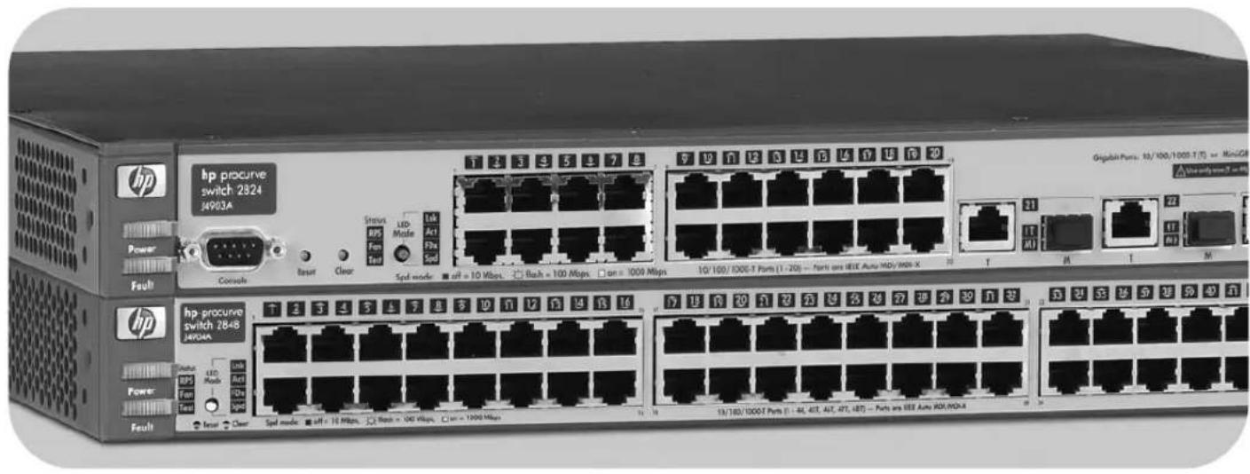
The IIP ProCurve Switch 2824 and Switch 2848 are multiport Gigabit switches that can be used to build high-performance switched workgroup networks. These switches are store-and-forward devices offering low latency for high-speed networking.
HP ProCurve Switch 2824 (HPJ4903A)
HP ProCurve Switch 2848 (HPJ4904A)
Throughout this manual, these switches will be abbreviated as the Switch 2824 or Switch 2848 and collectively as the Switch 2800 Series devices.
The Switch 2824 and Switch 2848 have, respectively, 24 or 48 auto-sensing 10/100/1000Base-T RJ-45 ports, four dual-personality ports—either auto-sensing 10/100/1000Base-T RJ-45 or mini-GBIC.
The Switch 2800 Series devices can be connected to an HP ProCurve EPS/RPS (J8168A) and receive full redundant power from that unit. If the internal power supply in the switch fails, the EPS/RPS unit will immediately provide all the power necessary to keep the switch running.
These switches are designed to be used primarily as a high-density wiring closet or desktop switch. These switches can directly connect computers, printers, and servers to provide dedicated bandwidth to those devices, and can build a switched network infrastructure by connecting the switch to hubs, other switches, or routers. In addition, the Switch 2800 Series devices offer full network management capabilities.
This chapter describes the HP ProCurve Switch 2824 and Switch 2848, including:
■front and back of the switches
■switch features
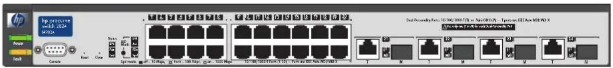
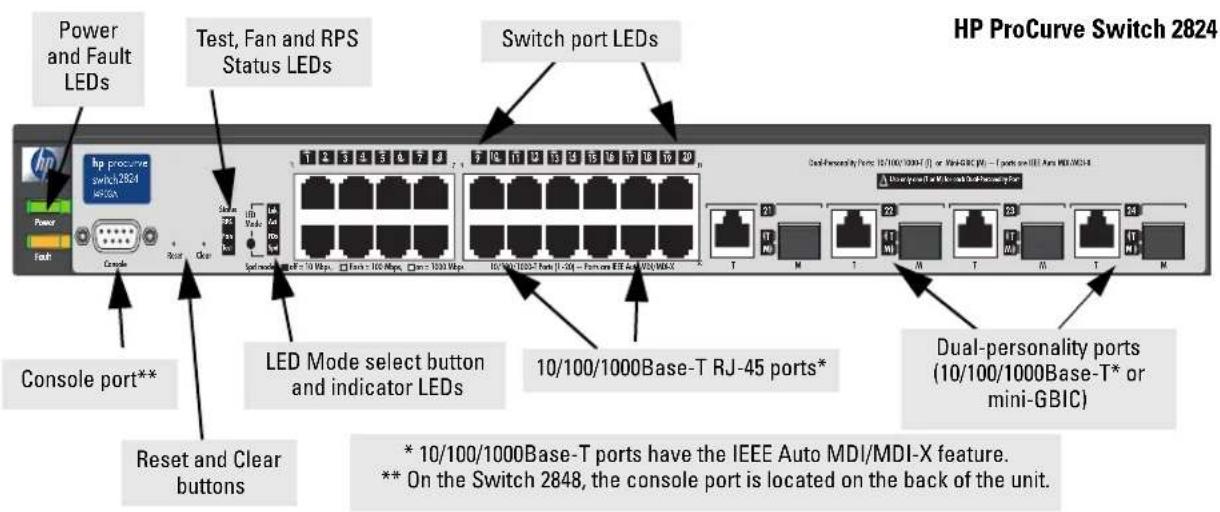
Front of the Switch
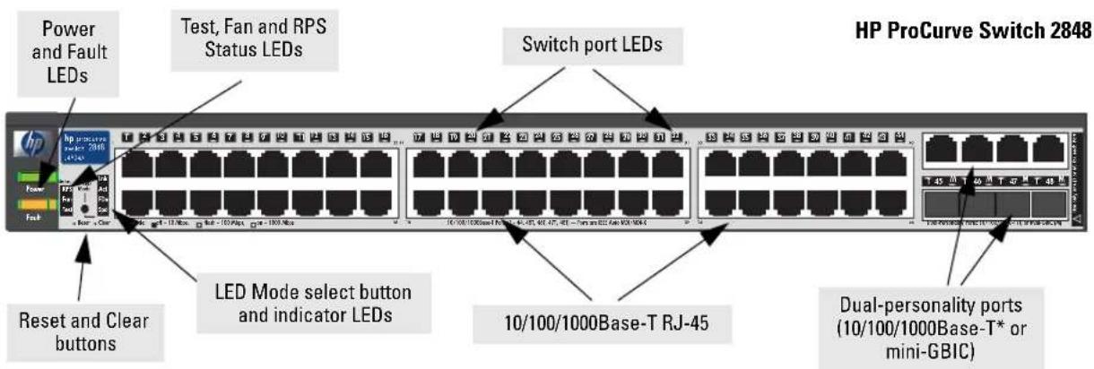
Network Ports
■24 or 48 auto-sensing 10/100/1000Base-T ports.
All these ports have the "IEEE Auto MDI/MDI-X" feature, which means you can use either straight-through or crossover twisted-pair cables to connect any network devices to the switch.
■ Four dual-personality ports. Use either the 10/100/1000Base-T RJ-45 connector, or install a supported HP ProCurve mini-GBIC for fiber-optic connections. The RJ-45 connectors support the IEEE Auto MDI/MDI-X feature, which means you can use either straight-through or crossover twisted-pair cables to connect any network device to the switch.
Dual-Personality Port Operation. By default, the RJ-45 connectors are enabled. If a mini-GBIC is installed in a slot, it is enabled and the associated RJ-45 connector is disabled and cannot be used. If the mini-GBIC is removed, the associated RJ-45 port is automatically re-enabled.
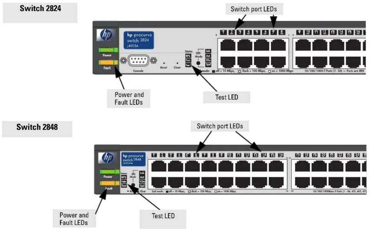
LEDs
Table 1-1. Switch LEDs
| Switch LEDs State Meaning | ||
| Power(green) | OnOff | The switch is receiving power.The switch is NOT receiving power. |
| Fault(orange) | OffBlinking*On | The normal state; indicates there are no fault conditions on the switch.A fault has occurred on the switch, one of the switch ports, or the fan. The Status LED for the component with the fault will blink simultaneously. If just the Fault LED is blinking, the switch could be attached to an RPS but not receiving power.On briefly after the switch is powered on or reset, at the beginning of switch self test. If this LED is on for a prolonged time, the switch has encountered a fatal hardware failure, or has failed its self test. See chapter 4, “Troubleshooting” for more information. |
| Test(green) | Off The normal operational state; the switch is not undergoing self test.OnBlinking* | The switch self test and initialization are in progress after the switch has been power cycled or reset. The switch is not operational until this LED goes off. The test LED also comes on briefly when you “hot swap” a mini-GBIC into the switch; the mini-GBIC is self tested when it is hot swapped.A component of the switch has failed its self test. The status LED for that component, for example an RJ-45 port, and the switch Fault LED will blink simultaneously. |
| Port LEDs(green – over-laid with the port number) | Displays port link information, network activity information, whether the port is configured for full-duplex operation, or the speed of the connection depending on the LED Mode selected. See “LED Mode Select Button and Indicator LEDs” on the next page for more information. | |
| LED Mode View (4 green LEDs) | Link Indicates that the port LEDs are displaying link information:if the port LED is on, the port is enabled and receiving a link indication from the connected device.if the port LED is off, the port has no active network cable connected, or is not receiving link beat or sufficient light. Otherwise, the port may have been disabled through the switch console or the web browser interface.if the port LED is blinking* simultaneously with the Fault LED, the corresponding port has failed its self test.Act Indicates the port LEDs are displaying network activity information.FDx Indicates port LEDs are lit for ports in Full Duplex Mode. Off indicates half duplex.Spd | Indicates the port LEDs are displaying the connection speed at which each port is operating:if the port LED is off, the port is operating at 10 Mbps.if the port LED is flashing**, the port is operating at 100 Mbps.if the port LED is on continuously, the port is operating at 1000 Mbps. |
| * The blinking behavior is an on/off cycle once every 1.6 seconds, approximately. | ||
| T/M(green - ports21 - 24 or 45-48) | On For the dual-personality ports, indicates the enabled connector:if the “T” is on, the 10/100/1000Base-T RJ-45 connector is enabled.if the “M” is on, the mini-GBIC connector is enabled. | |
| Fan Status(green) | On Normal operation, all fans are ok.Blinking* | One of the unit’s fans has failed. The switch Fault LED will be blinking simultaneously. |
| RPS Status(green) | OnBlinkingOff | Normal operation. An HP ProCurve EPS/RPS unit is connected and operating correctly.The EPS/RPS could be powering the unit - see table below.The EPS/RPS is connected but may be powering another switch or the EPS/RPS has experienced a fault.The EPS/RPS is not connected or is not powered. |
| * The blinking behavior is an on/off cycle once every 1.6 seconds, approximately. | ||
Table 1-2. EPS/RPS LED Behavior
| EPS/RPS modes: | This table describes the behavior of the EPS/RPS and LEDs associated with EPS/RPS operation (Power, EPS/RPS, Fault) | ||
| Power LEDs | EPS/RPS LED | Fault LED Description | |
| On Off Off Normal operation. | EPS/RPS is not connected or not powered | ||
| On On Off Normal operation. | EPS/RPS is available. | ||
| On On/Off Blinking Unit has experienced a fault and another LED will be blinking to determine fault. | |||
| Off On Blinking | EPS/RPS is running unit in failover mode. No AC power to the unit, or the internal power supply has failed | ||
| Off Off Off Unit is un-powered by AC input line and the external EPS/RPS | |||
| On Blinking Blinking EPS/RPS unit has experienced a fault | |||
| On Blinking Off | EPS/RPS unit is unavailable to power the unit in the event of an internal power supply failure. The external EPS/RPS is designed to provide power to one of its connected switch devices at a time. The Power Status LED on the external EPS/RPS unit will also be blinking for this device. | ||
LED Mode Select Button and Indicator LEDs
To optimize the amount of information displayed for each of the switch ports without overwhelming you with LEDs, the Switch 2800 Series devices use a single LED for each port. The operation of this LED is controlled by the LED Mode select button, and the current setting is indicated by the LED Mode indicator LEDs near the button. Press the button to step from one view mode to the next.
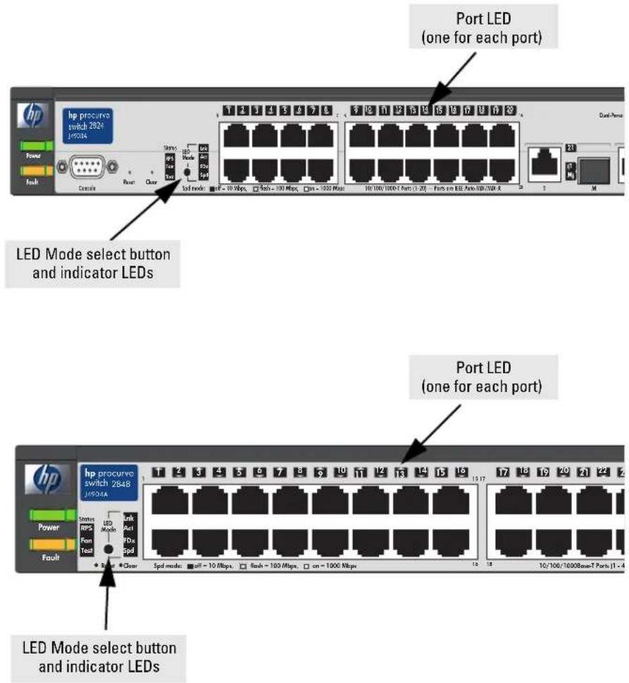
■ If the Link (LnK) indicator LED is lit, each port LED displays link information for the associated port.
If the port LED is in Link mode and it is blinking, the port has failed its self test. The Fault and Test LEDs will be blinking simultaneously.
If the Activity (Act) indicator LED is lit, each port LED displays activity information for the associated port—it flickers as network traffic is received and transmitted through the port.
■If the Full Duplex (FDx) indicator LED is lit, the port LEDs light for those ports that are operating in full duplex.
■ If the Speed (Spd) indicator LED is lit, the port LEDs behave as follows to indicate the connection speed for the port:
- Off = 10 Mbps
- Flashing = 100 Mbps (the flashing behavior is a repeated on/off cycle once every 0.5 sec.)
- On = 1000 Mbps
Reset Button
This button is used to reset the switch while it is powered on. This action clears any temporary error conditions that may have occurred and executes the switch self test.
Clear Button
This button is used for these purposes:
■ Deleting Passwords - When pressed by itself for at least one second, the button deletes any switch console access passwords that you may have configured. Use this feature if you have misplaced the password and need console access.
This button is provided for your convenience, but its presence means that if you are concerned with the security of the switch configuration and operation, you should make sure the switch is installed in a secure location, such as a locked wiring closet.
■ Restoring Factory Default Configuration - When pressed with the Reset button in a specific pattern, any configuration changes you may have made through the switch console, the web browser interface, and SNMP management are removed, and the factory default configuration is restored to the switch. For the specific method to restore the factory default configuration, see “Restoring the Factory Default Configuration” on page 11 in chapter 4, “Troubleshooting” of this manual.
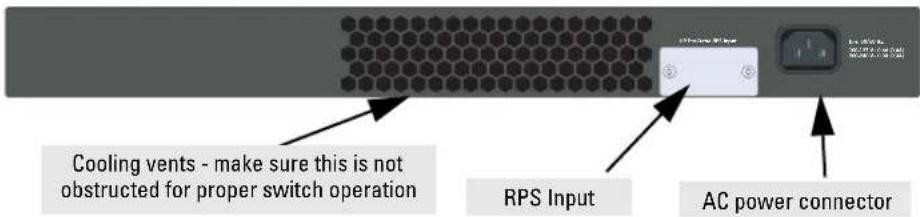
Back of the Switch
HP ProCurve Switch 2824 (HPJ4903A)
HP ProCurve Switch 2848 (HPJ4904A)
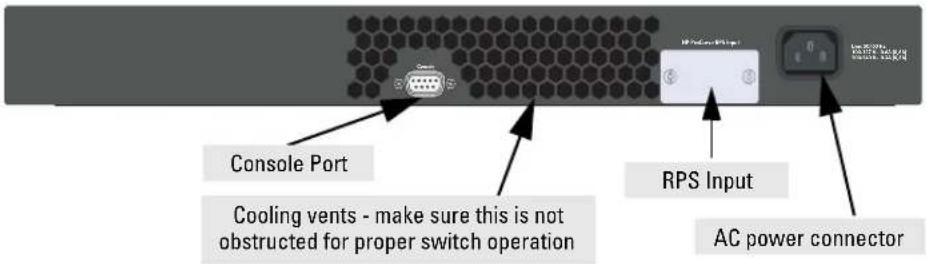
Console Port
This port is used to connect a console to the Switch 2800 Series devices by using the serial cable supplied with the switch. The console port is located on the front of the Switch 2824 and on the back of the Switch 2848. This connection is described under “Connect a Console to the Switch” in chapter 2, “Installing the Switch.” The console can be a PC or workstation running a VT-100 terminal emulator, or a VT-100 terminal.
Power Connector
The Switch 2800 Series devices do not have a power switch; they are powered on when connected to an active AC power source. These switches automatically adjust to any voltage between 100–240 volts and either 50 or 60 Hz. No voltage range settings are required.
Switch Features
The features of the Switch 2800 Series devices include:
■24 or 48 auto-sensing 10/100/1000Base-T RJ-45 ports.
■four dual-personality ports—either the auto sensing 10/100/1000Base-T RJ-45 or the mini-GBIC can be used for each port.
■ plug-and-play networking—all ports are enabled—just connect the network cables to active network devices and your switched network is operational.
■both switches support an external Redundant Power Supply (RPS).
- IEEE 802.3ab Auto MDI /MDI-X on all 10/100/1000 twisted-pair ports, meaning that all connections can be made using straight-through twisted-pair cables. Cross-over cables are not required, although they will also work. The pin operation of each port is automatically adjusted for the attached device: if the switch detects that another switch or hub is connected to the port, it configures the port as MDI; if the switch detects that an end-node device is connected to the port, it configures the port as MDI-X.
■ automatic learning of the network addresses in each switch's 8000-address forwarding table, (with configurable address aging value).
■automatically negotiated full-duplex operation for all 10/100/1000Base-T RJ-45 ports when connected to other auto-negotiating devices—the mini-GBIC ports always operate at full duplex.
■easy management of the switch through several available interfaces:
- console interface—a full featured, easy to use, VT-100 terminal interface that is especially good for out-of-band switch management or for Telnet access to the switch.
- web browser interface—an easy to use built-in graphical interface that can be accessed from common web browsers.
- HP ProCurve Manager—an SNMP based, graphical network managent tool you can use to manage your entire network. this product is included with your new switch.
■ support for the Spanning Tree Protocol to eliminate network loops.
■ support for up to 60 IEEE 802.1Q-compliant VLANs so you can divide the attached end nodes into logical groupings that fit your business needs.
■ support for many advanced features to enhance network performance—for a description, see the Management and Configuration Guide, which is on the Documentation CD-ROM included with the switch.
■ download of new switch software for product enhancements or bug fixes.
Installing the Switch
The HP ProCurve Switch 2800 Series devices are easy to install. They come with an accessory kit that includes the brackets for mounting the switch in a standard 19-inch telco rack, in an equipment cabinet, and with rubber feet that can be attached so the switch can be securely located on a horizontal surface. The brackets are designed to allow mounting the switch in a variety of locations and orientations. This chapter shows how to install the switch.
Included Parts
The Switch 2800 Series devices have the following components shipped with them:
■ HP ProCurve Switch 2800 Series Installation and Getting Started Guide (J4903-90001), this manual
■HP ProCurve Product Documentation CD ROM
(contains PDF file copies of the documentation for the Switch 2800 Series devices, including the Management and Configuration Guide, and for most other HP ProCurve switches)
■HP ProCurve Manager - CD ROM and booklet
■Console cable
■Customer Support/Warranty booklet
■Accessory kits
(5064-5085) for Switch 2824 (5069-5705) for Switch 2848
| two mounting brackets two mounting brackets* | |
| four 8-mm M4 screws to attach the mounting brackets to the switch | eight 8-mm M4 screws to attach the mounting brackets to the switch |
| four 5/8-inch number 12-24 screws to attach the switch to a rack | four 5/8-inch number 12-24 screws to attach the switch to a rack |
| four rubber feet four rubber feet | |
* These mounting brackets differ from the 5064-5085 mounting brackets by being longer to support the increased depth of the 2848 product (compared to the 2824).
Installing the Switch
Included Parts
■Power cord, one of the following:
| Australia/New Zealand | 8120-6803 |
| China | 8120-8377 |
| Continental Europe | 8120-6802 |
| Denmark | 8120-6806 |
| Japan | 8120-6804 |
| Switzerland | 8120-6807 |
| United Kingdom/Hong Kong/Singapore | 8120-8709 |
| United States/Canada/Mexico | 8120-6805 |
Installation Procedures
Summary
Follow these steps to install the switch. The rest of this chapter provides details on these steps.
- Prepare the installation site (page 2-5). Ensure the physical environment is properly prepared, including having the correct network cabling ready to connect to the switch and having an appropriate location for the switch. Please see page 2-4 for some installation precautions.
- Install mini-GBICs (optional—page 2-7). The switch has four slots for installing mini-GBICs. Depending on where you will install the switch, it may be easier to install the mini-GBICs first. Note that mini-GBICs can be hot swapped—they can be installed or removed while the switch is powered on.
- Verify the switch passes self test (page 2-9). This is a simple process of plugging the switch into a power source and observing that the LEDs on the switch's front panel indicate correct switch operation.
- Mount the switch (page 2-11). The Switch 2800 Series devices can be mounted in a 19-inch telco rack, in an equipment cabinet, or on a horizontal surface.
- Connect power to the switch (page 2-17). Once the switch is mounted, plug it into the nearby main power source.
- Connect the network cables (page 2-18). Using the appropriate network cables, connect the network devices to the switch ports.
- Connect a Redundant Power Supply (RPS), (optional—page 2-19). You may wish to use the RPS option on your Switch 2824 or Switch 2848. To do so you must connect the RPS using the cables supplied with the RPS, to the back of the switch.
- Connect a console to the switch (optional—page 2-22). You may wish to modify the switch's configuration, for example, to configure an IP address so it can be managed using a web browser, from an SNMP network management station, or through a Telnet session. Configuration changes can be made easily by using the included console cable to connect a PC to the switch's console port.
At this point, the switch is fully installed. See the rest of this chapter if you need more detailed information on any of these installation steps.
Installation Precautions:
Follow these precautions when installing the Switch 2800 Series devices.
Warning
■ The rack or cabinet should be adequately secured to prevent it from becoming unstable and/or falling over.
Devices installed in a rack or cabinet should be mounted as low as possible, with the heaviest devices at the bottom and progressively lighter devices installed above.
For safe operation, do not install the switch with the back face of the switch (with the fan vents) facing either downward or upward.
■ Left side vents cannot be placed downward. (That is, the left side of the unit while facing the front.)
■ Ensure the power source circuits are properly grounded, then use the power cord supplied with the switch to connect it to the power source.
If your installation requires a different power cord than the one supplied with the switch, be sure to use a power cord displaying the mark of the safety agency that defines the regulations for power cords in your country. The mark is your assurance that the power cord can be used safely with the switch.
■ When installing the switch, the AC outlet should be near the switch and should be easily accessible in case the switch must be powered off.
■Ensure the switch does not overload the power circuits, wiring, and over-current protection. To determine the possibility of overloading the supply circuits, add together the ampere ratings of all devices installed on the same circuit as the switch and compare the total with the rating limit for the circuit. The maximum ampere ratings are usually printed on the devices near the AC power connectors.
■ Do not install the switch in an environment where the operating ambient temperature might exceed 55^ C ( 131^ F).
■ Ensure the air flow around the sides and back of the switch is not restricted.
Cautions
1. Prepare the Installation Site
■ Cabling Infrastructure - Ensure the cabling infrastructure meets the necessary network specifications. See the following table for cable types and lengths, and see appendix B, “Cables and Connectors” for more information:
Table 2-1. Summary of Cable Types to Use With the Switch
| Port Type Cable Type Length Limits | |
| Twisted-Pair Cables | |
| 10/100/1000Base-T For either 10, 100 Mbps, or 1000 Mbps operation:Category 5 or better, 100-ohm UTP or shielded twisted-pair (STP) balanced cable. For 1000 Mbps (gigabit) operation, Category 5E cabling or better is recommended. | 100 metersNote:The Switch 2800 Series devices are compatible with the IEEE 802.3ab standard including the “Auto MDI/MDI-X” feature, which allows use of either straight-through or crossover twisted-pair cables for connecting to any network devices including end nodes, such as computers, or to other switches, hubs, and routers.Note:For 1000 Mbps operation, all four wire pairs are used for data transmission. |
| Port Type Cable Type Length Limits | ||
| Fiber Optic Cables | ||
| Gigabit-SX(on Gigabit-SX-LCmini-GBIC) | Multimode fiber-optic cables designed for Gigabit Ethernet: 62.5/125 μm or 50/125 μm (core/cladding) diameter, low metal content, graded-index cables, fitted with LC connectors. The cables must comply with the ITU-T G.651 and ISO/IEC 793-2 Type A1b or A1a standards. | • 62.5 μm cable: - 160 MHz*km = 220 meters - 200 MHz*km = 275 meters • 50 μm cable: - 400 MHz*km = 500 meters - 500 MHz*km = 550 meters |
| Gigabit-LX(on Gigabit-LX-LCmini-GBIC) | Single-mode fiber-optic cables designed for Gigabit Ethernet: 9/125 μm (core/cladding) diameter, 1310 nm, low metal content cables, fitted with LC connectors. The cables must comply with the ITU-T G.652 and ISO/IEC 793-2 Type B1 standards. The multimode cables specified for the Gigabit-SX mini-GBIC may also be used, but a mode-conditioning patch cord may be needed — see “Mode Conditioning Patch Cord for Gigabit-LX” on page B-3 for more information. | • single-mode cable = 5 kilometers • multimode cable = 550 meters |
| Gigabit-LH(on Gigabit-LH-LCmini-GBIC) | Single-mode fiber-optic cables designed for Gigabit Ethernet and fitted with LC connectors. | • single-mode cable = 70 kilometers |
■ Installation Location - Before installing the switch, plan its location and orientation relative to other devices and equipment:
- In the front of the switch, leave at least 7.6cm (3 inches) of space for the twisted-pair and fiber-optic cabling.
- In the back of the switch, leave at least 3.8cm (1 1/2 inches) of space for the power cord.
- On the sides of the switch, leave at least 7.6 cm (3 inches) for cooling, except if the switch is installed in an open EIA/TIA rack.
2. Installing or Removing mini-GBICs
You can install or remove a mini-GBIC from a mini-GBIC slot without having to power off the switch. Use only HP ProCurve mini-GBICs.
Notes
■ The mini-GBIC slots are shared with the four 10/100/1000Base-T RJ-45 ports. If a mini-GBIC is installed in a slot, the associated RJ-45 port is disabled and cannot be used.
■ The mini-GBIC ports operate only at full duplex. Half duplex operation is not supported.
■ Ensure the network cable is NOT connected when you install or remove a mini-GBIC.
When this manual was printed, the supported mini-GBICs include the following:
■HP ProCurve Gigabit-SX-LC mini-GBIC (J4858A)
■HP ProCurve Gigabit-LX-LC mini-GBIC (J4859A)
■HP ProCurve Gigabit-LH-LC mini-GBIC (J4860A)
Caution
The HP ProCurve mini-GBICs are Class 1 laser devices. Avoid direct eye exposure to the beam coming from the transmit port.
Installing the mini-GBICs:
Hold the mini-GBIC by its sides and gently insert it into either of the slots on the switch until the mini-GBIC clicks into place.
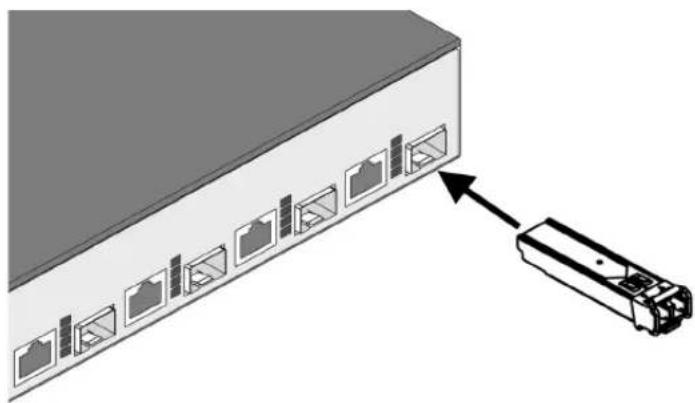
natural_image
Diagram of a network switch with multiple Ethernet ports and an attached device (no text or symbols)Removing the mini-GBICs:
Note
You should disconnect the network cable from the mini-GBIC before removing it from the switch.
Depending on when you purchased your HP ProCurve mini-GBIC, it may have either of three different release mechanisms: a plastic tab on the bottom of the mini-GBIC, a plastic collar around the mini-GBIC, or a wire bail.
To remove the mini-GBICs that have the plastic tab or plastic collar, push the tab or collar toward the switch until you see the mini-GBIC release from the switch (you can see it move outward slightly), and then pull it from the slot.
To remove the mini-GBICs that have the wire bail, lower the bail until it is approximately horizontal, and then using the bail, pull the mini-GBIC from the slot.
3. Verify the Switch Passes Self Test
Before mounting the switch in its network location, you should first verify it is working properly by plugging it into a power source and verifying it passes self test.
- Connect the power cord supplied with the switch to the power connector on the back of the switch, and then into a properly grounded electrical outlet.
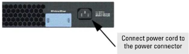
Note
The Switch 2800 Series devices do not have a power switch. They are powered on when the power cord is connected to the switch and to a power source. For safety, the power outlet should be located near the switch installation.
The switch automatically adjusts to any voltage between 100-240 volts and either 50 or 60 Hz. No voltage range settings are required.
If your installation requires a different power cord than the one supplied with the switch, be sure to use a power cord displaying the mark of the safety agency that defines the regulations for power cords in your country. The mark is your assurance that the power cord can be used safely with the switch.
Installing the Switch Installation Procedures
- Check the LEDs on the switch as described below.
When the switch is powered on, it performs its diagnostic self test. Self test takes approximately 50 seconds to complete.
LED Behavior:
During the self test:
- Initially, all the status, LED Mode and port LEDs are on for most of the duration of the test.
- Most of the LEDs go off and then may come on again during phases of the self test. For the duration of the self test, the Test LED stays on.
When the self test completes successfully:
• The Power and Fan Status LEDs remain on.
• The Fault and Test LEDs go off.
- The port LEDs on the front of the switch go into their normal operational mode:
- If the ports are connected to active network devices, the LEDs behave according to the LED Mode selected. In the default view mode (Link), the LEDs should be on.
- If the ports are not connected to active network devices, the LEDs will stay off.
If the LED display is different than what is described above, especially if the Fault and Test LEDs stay on for more than 60 seconds or they start blinking, the self test has not completed correctly. Refer to chapter 4, "Troubleshooting" for diagnostic help.
4. Mount the Switch
After the switch passes self test, you are ready to mount the switch in a stable location. The Switch 2800 Series devices can be mounted in these ways:
■in a rack or cabinet
■on a horizontal surface
Rack or Cabinet Mounting
The Switch 2800 Series devices are designed to be mounted in any EIA-standard 19-inch telco rack or communication equipment cabinet.
Warning For safe operation, please read the mounting precautions on page 2-4, before mounting a switch.
Equipment Cabinet Note
The 12-24 screws supplied with the switch are the correct threading for standard EIA/TIA open 19-inch racks. If you are installing the switch in an equipment cabinet such as a server cabinet, use the clips and screws that came with the cabinet in place of the 12-24 screws that are supplied with the switch.
Complete step 1, and plan which four holes you will be using in the cabinet and install all four clips. Then proceed to step 2.
Rack Mounting the Switch 2848
- Use a #1 Phillips (cross-head) screwdriver and attach the mounting brackets to the switch with the included 8-mm M4 screws.
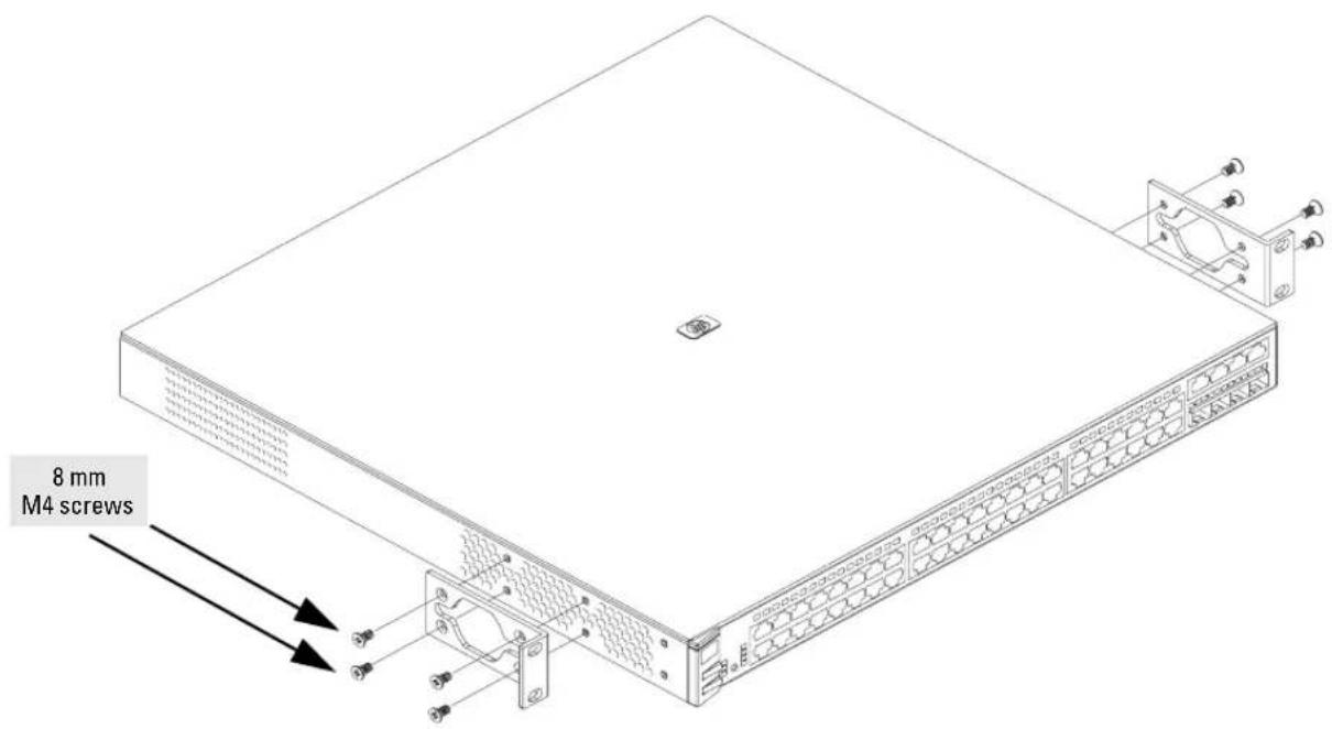
Note
The mounting brackets have multiple mounting holes and can be rotated allowing for a wide variety of mounting options. These include mounting the switch so its front face is flush with the face of the rack, or mounting it in a more balanced position as shown in the illustration.
- Hold the switch with attached brackets up to the rack and move it vertically until rack holes line up with the bracket holes, then insert and tighten the four number 12-24 screws holding the brackets to the rack.
natural_image
Technical line drawing of a server rack with mounting bracket and side panel, showing internal components and mounting details (no text or symbols)Rack Mounting the Switch 2824
- Use a #1 Phillips (cross-head) screwdriver and attach the mounting brackets to the switch with the included 8-mm M4 screws.
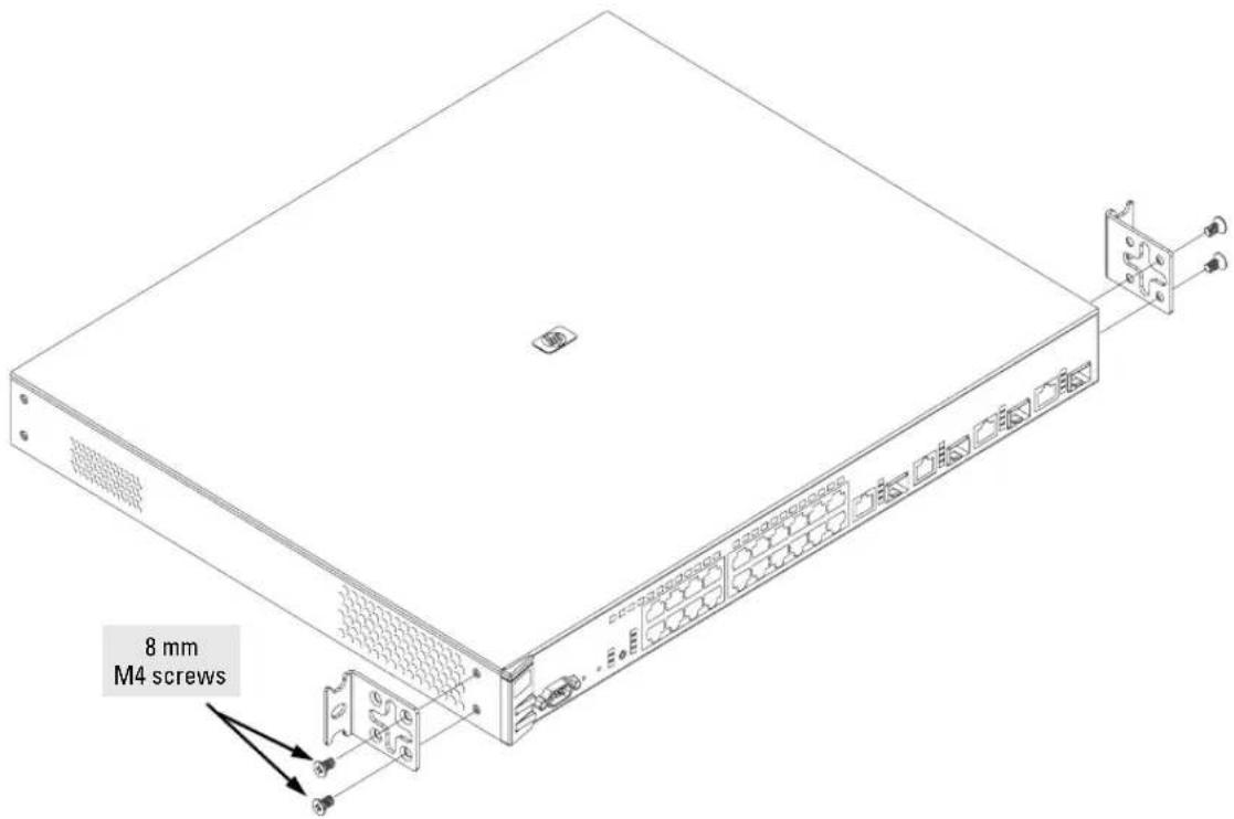
Note
The mounting brackets have multiple mounting holes and can be rotated allowing for a wide variety of mounting options. These include mounting the switch so its front face is flush with the face of the rack, or mounting it in a more balanced position as shown in the illustration.
Steps 2, 3, and 4 on the following pages describe a convenient method of mounting the switch in a rack by placing it on two screws that you first install in the rack. You may, instead, just hold the switch with attached brackets up to the rack and move it vertically until rack holes line up with the bracket holes and notches, then insert and tighten the four screws holding the brackets to the rack.
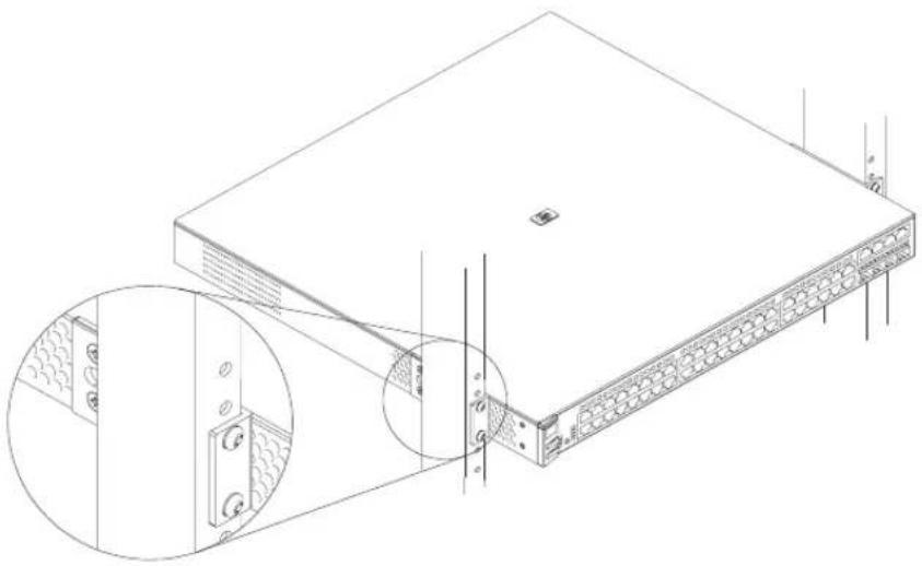
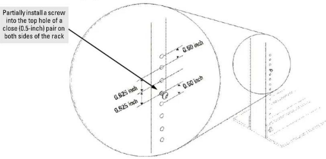
- Partially install a screw (5/8-inch number 12-24) into the top hole of a pair of holes that are 0.5 inches apart in each rack/cabinet upright as shown in the illustration below. Ensure that the screws are at the same level in each upright.
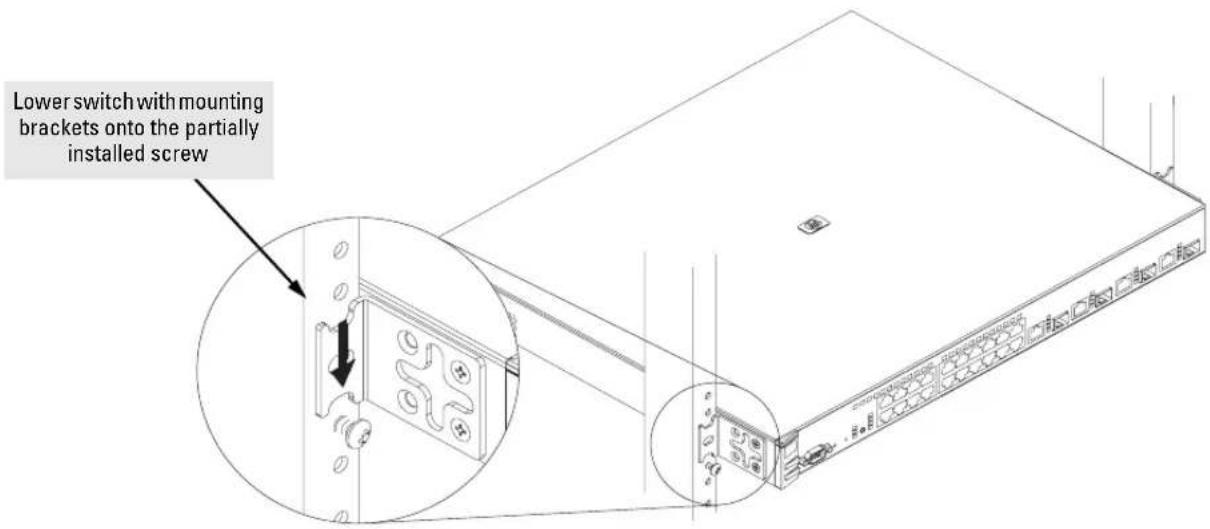
- Place the switch in the rack and lower it so the notches in the bottom of the bracket slide onto the screws, then tighten these screws.
Installing the Switch Installation Procedures
- Install the other number 12-24 screw into the upper hole in each bracket. Tighten these screws.
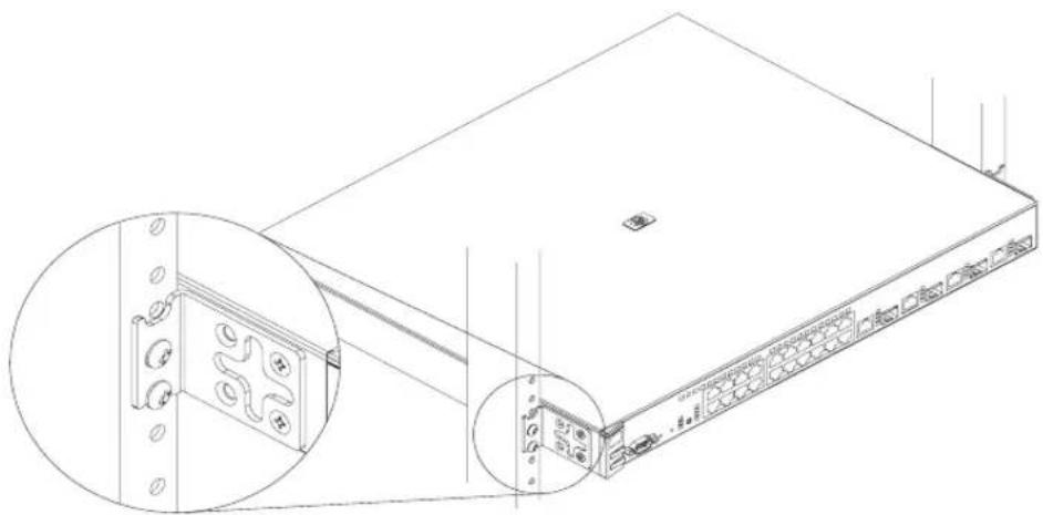
natural_image
Technical line drawing of a server rack with an inset close-up showing internal components (no text or symbols)Horizontal Surface Mounting
Place the switch on a table or other horizontal surface. The switch comes with rubber feet in the accessory kit that can be used to help keep the switch from sliding on the surface.
Attach the rubber feet to the four corners on the bottom of the switch within the embossed angled lines. Use a sturdy surface in an uncluttered area. You may want to secure the networking cables and switch power cord to the table leg or other part of the surface structure to help prevent tripping over the cords.
Caution
Make sure the air flow is not restricted around the sides and back of the switch.
5. Connect the Switch to a Power Source
- Plug the included power cord into the switch's power connector and into a nearby AC power source.
- Re-check the LEDs during self test. See "LED Behavior" on page 2-10
6. Connect the Network Cables
Connect the network cables, described under “Cabling Infrastructure” (page 2-5), from the network devices or your patch panels to the fixed RJ-45 ports on the switch or to any mini-GBICs you have installed in the switch.
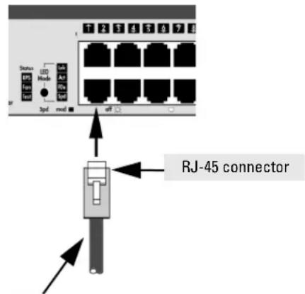
Using the RJ-45 Connectors
To connect:
Push the RJ-45 plug into the RJ-45 jack until the tab on the plug clicks into place. When power is on for the switch and for the connected device, the Link LED for the port should light to confirm a powered-on device (for example, an end node) is at the other end of the cable.
If the Link LED does not go on when the network cable is connected to the port, see “Diagnosing with the LEDs” on page 4-4, in chapter 4, “Troubleshooting”.
To disconnect:
Press the small tab on the plug and pull the plug out of the jack.
Unshielded twisted-pair cable:
• Category 3, 4, or 5 for 10 Mbps ports
- Category 5 or better for 100 Mbps ports
- Category 5E or better for 1000 Mbps ports
Maximum distance: 100 meters
Connecting Cables to mini-GBICs
Note
Each of the four mini-GBIC slots is shared with the associated 10/100/1000Base-T RJ-45 port. If a mini-GBIC is installed in a slot, the associated RJ-45 port is disabled.
If you have any mini-GBICs installed in the switch, the type of network connections you will need to use depends on the type of mini-GBICs you have installed. See the table on page 2-6, and appendix B, “Switch Ports and Network Cables”, for the mini-GBIC cabling information.
For mini-GBICs ports, and in general for all the switch ports, when a network cable from an active network device is connected to the port, the port LED for that port should go on. If the port LED does not go on when the network cable is connected to the port, see “Diagnosing with the LEDs” on page 4-4 in chapter 4, “Troubleshooting”.
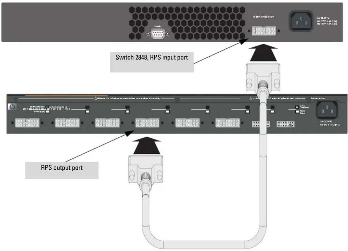
7. (Optional) Connect a Redundant Power Supply to the Switch
The “HP ProCurve 600 External and Redundant Power Supply (hereafter referred to as the EPS/RPS)” (J8168A) is an accessory product for the Switch 2800 Series devices and specific other HP ProCurve switches. The EPS/RPS provides redundant power to any one of up to six switch products, to back up the power supply in the switch in case of loss of AC power, or a fault condition. The EPS/RPS is an unmanaged power supply that only provides information by way of LEDs or through the port interfaces to attached devices.
Operating Characteristics
The EPS/RPS has six connectors, each of which can provide redundant +12V power to a connected switch, but only one connector can provide this power at a given time. If a switch with no AC power is connected to an operating EPS/RPS, it will NOT immediately power up this new switch. Power can only be provided to a switch if it is first powered on and operating correctly. Then when the power to the switch fails, power will be provided from the EPS/RPS, if it is available, that is, if the EPS/RPS is not already providing power to a higher priority switch. If two or more devices fail, priority goes to the device plugged into the lower numbered port on the EPS/RPS unit. Consequently the most important switch must be plugged into port one on the EPS/RPS. In this state, the “Connected” LED should be ON, and the “Power Status” LED should be BLINKING. (Refer to the documentation that came with your EPS/RPS.)
Connect the EPS/RPS to the switch using one of the 6 supplied RPS cables.
LEDs
The RPS LEDs are located on the back of the EPS/RPS. These LEDs are duplicated on the front of the device for your convenience. The following graphic shows an example of the back of the EPS/RPS. There are two green LEDs for each RPS port:
■Device Connected
■Power Status
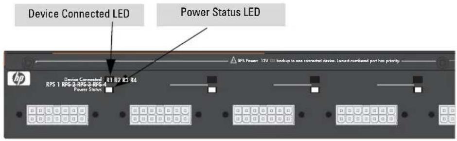
The following states provide status of an EPS/RPS port.
| Fault | Device Connected | Power Status | Message |
Off Off Off Nothing Connected
On or Off Off On Not a valid state - should never happen
Off On Off Switch is connected, RPS is available but not required
Off On On RPS is powering the connected device
Blinking Off Blinking RPS port is in fault mode
Off On Blinking Switch is requesting power, RPS can not provide it
Blinking On Off Switch is unplugged, but RPS is powering switch
The following picture demonstrates and example of connectivity between an EPS/RPS device and a Switch device.
EPS/RPS Operation
The EPS/RPS monitors the power signal from the switch by detecting that the EPS/RPS is connected to a switch with an EPS/RPS cable. When the power from the switch is no longer detected, the EPS/RPS will turn on and provide power to the switch within 1ms.
The EPS/RPS supports hot plugging of the EPS/RPS cable without causing a reboot of the switch or causing the power supply in either the EPS/RPS or switch to shut down temporarily or permanently. For more information refer to the documentation that came with the EPS/RPS.
8. (Optional) Connect a Console to the Switch
The switch has a full-featured, easy to use console interface for performing switch management tasks including the following:
■Monitor switch and port status and observe network activity statistics
■Modify the switch's configuration to optimize switch performance, enhance network traffic control, and improve network security
- Read the event log and access diagnostic tools to help in troubleshooting
■Download new software to the switch
■Add passwords to control access to the switch from the console, web browser interface, and network management stations
The console can be accessed through these methods:
■ Out-of-band: The switch comes with a serial cable for connecting a PC or VT-100 terminal, to be used as a console, directly to the switch.
In-Band: Access the console using Telnet from a PC or UNIX station on the network, and a VT-100 terminal emulator. This method requires that you first configure the switch with an IP address and subnet mask by using either out-of-band console access or through DHCP/Bootp. For more information on IP addressing and on starting a Telnet session, see chapter 3, “Configuring the Switch”, and the Management and Configuration Guide, which is on the Documentation CD-ROM that came with your switch.
The Switch can simultaneously support one out-of-band console session through the Console Port and one in-band Telnet console session.
Terminal Configuration
To connect a console to the switch, configure the PC terminal emulator as a DEC VT-100 (ANSI) terminal or use a VT-100 terminal, and configure either one to operate with these settings:
- any baud rate from 1200 to 115200 (the switch senses the speed)
- 8 data bits, 1 stop bit, no parity, and flow control set to Xon/Xoff
- For the Windows Terminal program, also disable (unchecked) the "Use Function, Arrow, and Ctrl Keys for Windows" option
- For the Hilgraeve HyperTerminal program, select the "Terminal keys" option for the "Function, arrow, and ctrl keys act as" parameter.
If you want to operate the console using a different configuration, make sure you change the settings on both the terminal and on the switch so they are compatible. Change the switch settings first, save your changes, then change the terminal settings, then reboot the switch and reestablish the console session.
Direct Console Access
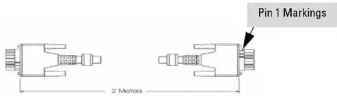
To connect a console to the switch, follow these steps:
- Connect the PC or terminal to the switch's Console Port using the console cable included with the Switch. (If your PC or terminal has a 25-pin serial connector, first attach a 9-pin to 25-pin straight-through adapter at one end of the console cable.)
- Turn on the terminal or PC's power and, if using a PC, start the PC terminal program.
- Press [Enter] two or three times and you will see the copyright page and the message "Press any key to continue". Press a key, and you will then see the switch console command (CLI) prompt, for example:
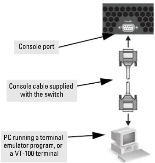
flowchart
graph TD
    A["Console port"] --> B["Switch"]
    B --> C["PC running a terminal emulator program, or a VT-100 terminal"]
    D["Console cable supplied with the switch"] --> B
This picture demonstrates the Switch 2848. Remember the console port on the Switch 2824 is in front.
HP ProCurve Switch 2848#
If you want to continue with console management of the switch at this time, see chapter 3, "Configuring the Switch" for some basic configuration steps. For more detailed information, refer to the Management and Configuration Guide, which is on the Documentation CD-ROM that came with the switch.
Sample Network Topologies
This section shows a few sample network topologies in which the Switch is implemented. For more topology information, see the HP network products World Wide Web site, http://www.hp.com/go/hpprocurve.
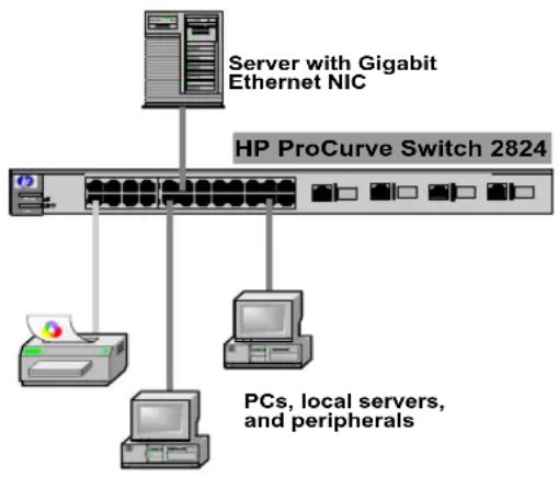
As a Desktop Switch
flowchart
graph TD
    A["Server with Gigabit Ethernet NIC"] --> B["HP ProCurve Switch 2824"]
    B --> C["PCs, local servers, and peripherals"]
    B --> D["Printer"]
    B --> E["Computer"]
LEGEND: Gigabit Ethernet cable Fast Ethernet cable
The Switch is designed to be used primarily as a desktop switch to which end nodes, printers and other peripherals, and servers are directly connected, as shown in the above illustration. Notice that the end node devices are connected to the switch by “straight-through” or “crossover” twisted-pair cables. Either cable type can be used because of the “IEEE Auto MDI/MDI-X” features on the Switch.
As a Segment Switch
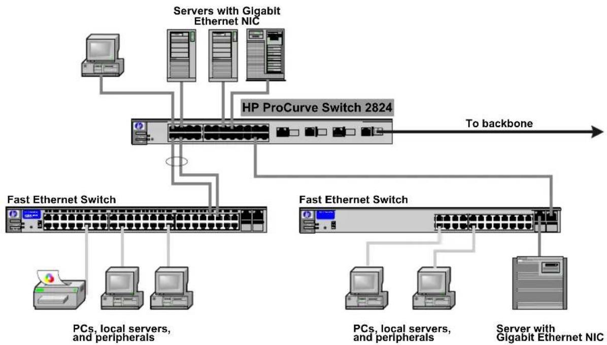
flowchart
graph TD
    A["PCs, local servers, and peripherals"] --> B["Fast Ethernet Switch"]
    C["Server with Gigabit Ethernet NIC"] --> D["HP ProCurve Switch 2824"]
    B --> E["To backbone"]
    D --> E
    F["Server with Gigabit Ethernet NIC"] --> G["Fast Ethernet Switch"]
    G --> H["PCs, local servers, and peripherals"]
    G --> I["Server with Gigabit Ethernet NIC"]
LEGEND: — Fast Ethernet cable — Gigabit Ethernet cable — Fiber cable
The Switch also works well as a segment switch. That is, with its high performance, it can be used for interconnecting network segments—simply connect the network hubs that form those segments to the switch, or you can also connect other switches.
In the illustration above, two “Fast” Ethernet hubs with PCs, printers, and local servers attached, are both connected to a Switch. The devices attached to the two hubs can now communicate with each other through the switch. They can also all communicate with the server that is connected to a 1000Base-T port on the switch.
Because the Switch has the “IEEE Auto MDI/MDI-X” features, the connections between the switch and the hubs, and between the switch and end nodes or servers can be through category 5 “straight-through” or “crossover” twisted-pair cable. Category 3 or 4 cable can also be used if the connection is 10 Mbps only. In all cases, the device ports must be configured to auto negotiate the link characteristics for this feature to work.
The switch, in turn, can be connected to a network backbone through fiber-optic cabling connected to a Gigabit-SX, -LX, or -LH mini-GBIC installed in the switch. Now, all the devices on these network segments can access other network resources that are connected elsewhere on the network backbone.
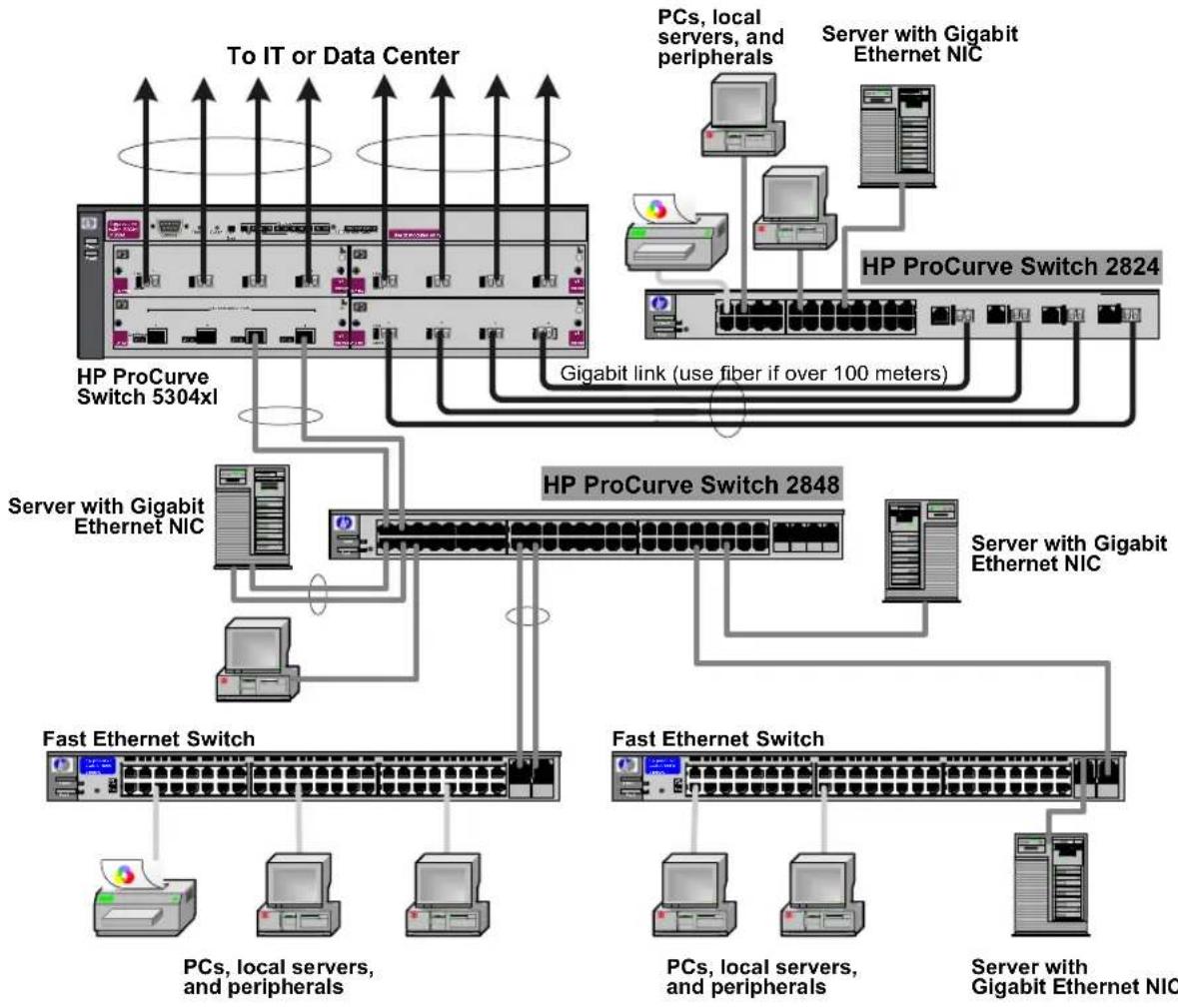
Connecting to a Backbone Switch
flowchart
graph TD
    A["To IT or Data Center"] --> B["HP ProCurve Switch 5304xl"]
    B --> C["Server with Gigabit Ethernet NIC"]
    C --> D["Fast Ethernet Switch"]
    D --> E["PCs, local servers, and peripherals"]
    D --> F["PCs, local servers, and peripherals"]
    D --> G["PCs, local servers, and peripherals"]
    H["PCs, local servers, and peripherals"] --> I["Server with Gigabit Ethernet NIC"]
    J["Server with Gigabit Ethernet NIC"] --> K["Server with Gigabit Ethernet NIC"]
    L["Server with Gigabit Ethernet NIC"] --> M["Server with Gigabit Ethernet NIC"]
    N["Gigabit link (use fiber if over 100 meters)"] --> B
    O["HP ProCurve Switch 2824"] --> P["Server with Gigabit Ethernet NIC"]
    Q["HP ProCurve Switch 2848"] --> R["Server with Gigabit Ethernet NIC"]
    S["To IT or Data Center"] --> T["To IT or Data Center"]
    U["To IT or Data Center"] --> V["To IT or Data Center"]
LEGEND: Fast Ethernet cable — Gigabit Ethernet cable — Fiber cable
The simpler desktop and segment networks shown in the previous two examples can easily be combined and expanded. For example, you could use an HP ProCurve Switch 5304xl to interconnect each of your smaller switched workgroups to form a larger switched network. All the devices in this network can communicate with each other. With a Gigabit-SX Module, for example, in the Switch 5304xl, the entire switched topology could be connected to a campus backbone, as shown in the illustration above.
Note
In the Backbone Switch illustration, the 1000 Mbps fiber-optic connection between the Switch 2824 and the Switch 5304xl is by way of a Gigabit-SX mini-GBIC installed in the Switch 2824 and connected to a Gigabit-SX Module in the Switch 5304xl.
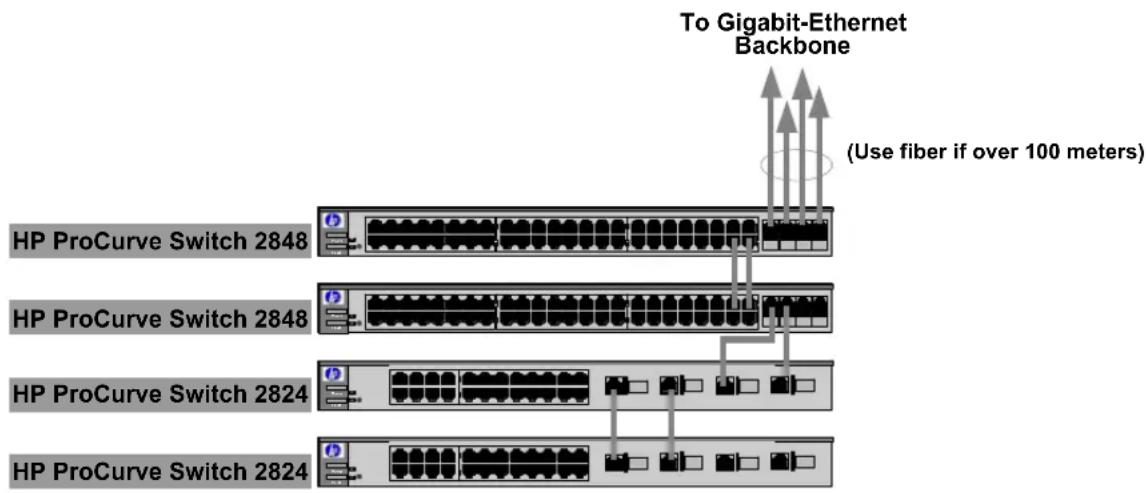
Stacking the Switch
The Switch 2800 Series devices can be connected together, through standard network connections, and managed through a single IP address. Up to 16 switches can be connected together in such a “virtual stack”.
You identify the switch as the “Commander” and give that switch an IP address. Up to 15 other switches in the network can then easily be configured as Members of the stack and managed through the Commander’s IP address. The management includes Telnet access and web browser interface access to the Commander and to each Member switch through the Commander.
For more information on stacking Switches, please see the Management and Configuration Guide, which is on the Documentation CD-ROM that came with the switch.
LEGEND: Gigabit Ethernet cable
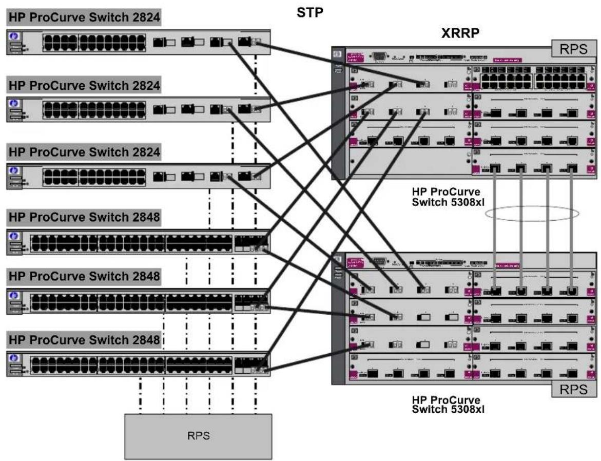
The Switch in a Redundant Topology
The redundant topology increases the availability of a single switch by protecting against single points of failure with the use of redundant switches and power supplies (RPS).
All hardware and paths are redundant. If any hardward failure occurs, I/O communication can still be completed through another path.
flowchart
graph TD
    subgraph STP
        A["HP ProCurve Switch 2824"] --> B["XRRP"]
        C["HP ProCurve Switch 2824"] --> B
        D["HP ProCurve Switch 2824"] --> B
        E["HP ProCurve Switch 2824"] --> B
        F["HP ProCurve Switch 2848"] --> G["XRRP"]
        H["HP ProCurve Switch 2848"] --> G
        I["HP ProCurve Switch 2848"] --> G
        J["HP ProCurve Switch 2848"] --> G
        K["HP ProCurve Switch 2848"] --> G
    end
    L["RPS"] --> M["HP ProCurve Switch 5308xl"]
    M --> N["XRRP"]
    N --> O["RPS"]
    style STP fill:#f9f,stroke:#333
    style XRRP fill:#ccf,stroke:#333
    style RPS fill:#cfc,stroke:#333
LEGEND: — Gigabit Ethernet cable — Fiber cable — Power
Installing the Switch
Sample Network Topologies
Configuring the Switch
This chapter is a guide for using the console Switch Setup screen to quickly assign an IP (Internet Protocol) address and subnet mask to the switch, set a Manager password, and, optionally, configure other basic features.
For more information on using the switch console and the other switch management interfaces: the web browser interface, please see the Management and Configuration Guide, which is on the Documentation CD-ROM that came with your switch.
Recommended Minimal Configuration
In the factory default configuration, the switch has no IP (Internet Protocol) address and subnet mask, and no passwords. In this state, it can be managed only through a direct console connection. To manage the switch through in-band (networked) access, you should configure the switch with an IP address and subnet mask compatible with your network. Also, you should configure a Manager password to control access privileges from the console and web browser interface. Other parameters in the Switch Setup screen can be left at their default settings or you can configure them with values you enter.
Many other features can be configured through the switch's console interface, to optimize the switch's performance, to enhance your control of the network traffic, and to improve network security. Once an IP address has been configured on the switch, these features can be accessed more conveniently through a remote Telnet session, through the switch's web browser interface, and from an SNMP network management station running a network management program. For a listing of switch features available with and without an IP address, refer to "How IP Addressing Affects Switch Operation" in the Management and Configuration Guide, which is on the Documentation CD-ROM that came with your switch.
For more information on IP addressing, refer to “IP Configuration” in the Management and Configuration Guide.
Note
By default, the switch is configured to acquire an IP address configuration from a DHCP or Bootp server. To use DHCP/Bootp instead of the manual method described in this chapter, see “DHCP/Bootp Operation” in the Management and Configuration Guide, which is on the Documentation CD-ROM that came with your switch.
Using the Console Setup Screen
The quickest and easiest way to minimally configure the switch for management and password protection in your network is to use a direct console connection to the switch, start a console session, and access the Switch Setup screen.
- Using the method described in the preceding section, connect a terminal device to the switch and display the switch console command (CLI) prompt (the default display).
The CLI prompt appears displaying the switch model number, for example:
HP ProCurve Switch 2824#
- At the prompt, enter the setup command to display the Switch Setup screen. The following illustration shows the Setup screen with the default settings.
![HE ProCurve Switch 2824 1-Jan-1990 2:59:24 CONSOLE - MANAGER MODE - Switch Setup System Name : HP ProCurve Switch 2824 System Contact : Manager Password : Confirm Password : Logon Default : CLI Time Zone [0] : 0 Community Name : public Spanning Tree Enabled [No] : No Default Gateway : Time Sync Method [None] : TIMED TimeP Mode [Disabled] : Disabled IP Config [DHCP/Bootp] : DHCP/Bootp IP Address : Subnet Mask : Actions-> Cancel Edit Save Help Enter System Name - up to 25 characters. Use arrow keys to change field selection, to toggle field choices, and to go to Actions.](/content/2026/05/818464/images/56ec636983a7412dee84281ecdaf7ce1a86f78ebe2f304a46d0fda6511f5a47a.jpg)
-
Use the [Tab] key to select the Manager Password field and enter a manager password of up to 16 characters.
-
[Tab] to the IP Config (DHCP/Bootp) field and use the Space bar to select the Manual option.
- [Tab] to the IP Address field and enter the IP address that is compatible with your network.
- [Tab] to the Subnet Mask field and enter the subnet mask used for your network.
- Press [ Enter], then [S] (for ).
Here is some information on the fields in the Setup screen. For more information on these fields, see the Management and Configuration Guide, which is on the Documentation CD-ROM that came with your switch:
Parameter Default
| System Name blank Optional; up to 25 characters, including spaces | ||
| System Contact blank Optional; up to 48 characters, including spaces | ||
| Manager Password blank Recommended; up to 16 characters (no blank spaces) | ||
| Logon Default | CLI | The default setting selects the command line interface for console access. The alternative is the menu interface. |
| Time Zone | 0 (none) | Optional; 1440 to -1440. The number of minutes your location is to the West (-) or East (+) of GMT. |
| Community Name public Default setting recommended. | ||
| Spanning Tree Enabled | No | Default setting recommended unless STP is already running on your network or the switch will be used in complex network topologies. |
| Default Gateway | blank | Optional; Enter the IP address of the next-hop gateway node if network traffic needs to be able to reach off-subnet destinations. |
| Time Sync Method | None | Optional; The protocol the switch uses to acquire a time signal. The options are SNTP and TimeP. |
| TimeP Mode | Disabled | Optional; The method the switch uses to acquire the TimeP server address. |
| IP Config (DHCP/Bootp) | DHCP/Bootp | Set to Manual unless a DHCP/Bootp server is used on your network to configure IP addressing. |
| IP Address | xxx.xxx.xxx.xxx | Recommended; If you set IP Config to Manual, then enter an IP address compatible with your network. |
| Note: The IP address and subnet mask assigned for the switch must be compatible with the IP addressing used in your network. For more information on IP addressing, see the Management and Configuration Guide, which is on the Documentation CD-ROM that came with your switch. | ||
| Subnet Mask | xxx.xxx.xxx.xxx | Recommended; If you entered an IP address, then enter a subnet mask compatible with your network. |
Where to Go From Here
The above procedure configures your switch with a Manager password, IP address, and subnet mask. As a result, with the proper network connections, you can now manage the switch from a PC equipped with Telnet or a web browser interface.
Some basic information on managing your switch is included in the next section. For more information on the console, web browser, and SNMP management interfaces and all the features that can be configured on the Switch 2800 Series devices, please see the Management and Configuration Guide, which is on the Documentation CD-ROM that came with your switch.
To Recover from a Lost Manager Password: If you cannot start a console session at the manager level because of a lost Manager password, you can clear all passwords and user names by getting physical access to the switch and pressing and holding the Clear button for a full second.
Using the IP Address for Remote Switch Management
With the Switch 2800 Series devices, you can use the switch's IP address to manage the switch from any PC that is on the same subnet as the switch. You can use either a Telnet session or a standard web browser to manage the switch.
Starting a Telnet Session
To access the switch through a Telnet session, follow these steps:
- Make sure the switch is configured with an IP address and that the switch is reachable from the PC that is running the Telnet session (for example, by using a Ping command to the switch's IP address).
- Start the Telnet program on a PC that is on the same subnet as the switch and connect to the switch's IP address.
- You will see the copyright page and the message "Press any key to continue". Press a key, and you will then see the switch console command (CLI) prompt, for example:
HP ProCurve Switch 2824#
Enter help or ? to see a list of commands that can be executed at the prompt. Entering any command followed by help provides more detailed context help information about the command. Entering any command followed by ? displays a list of options that are available at that point in the command entry.
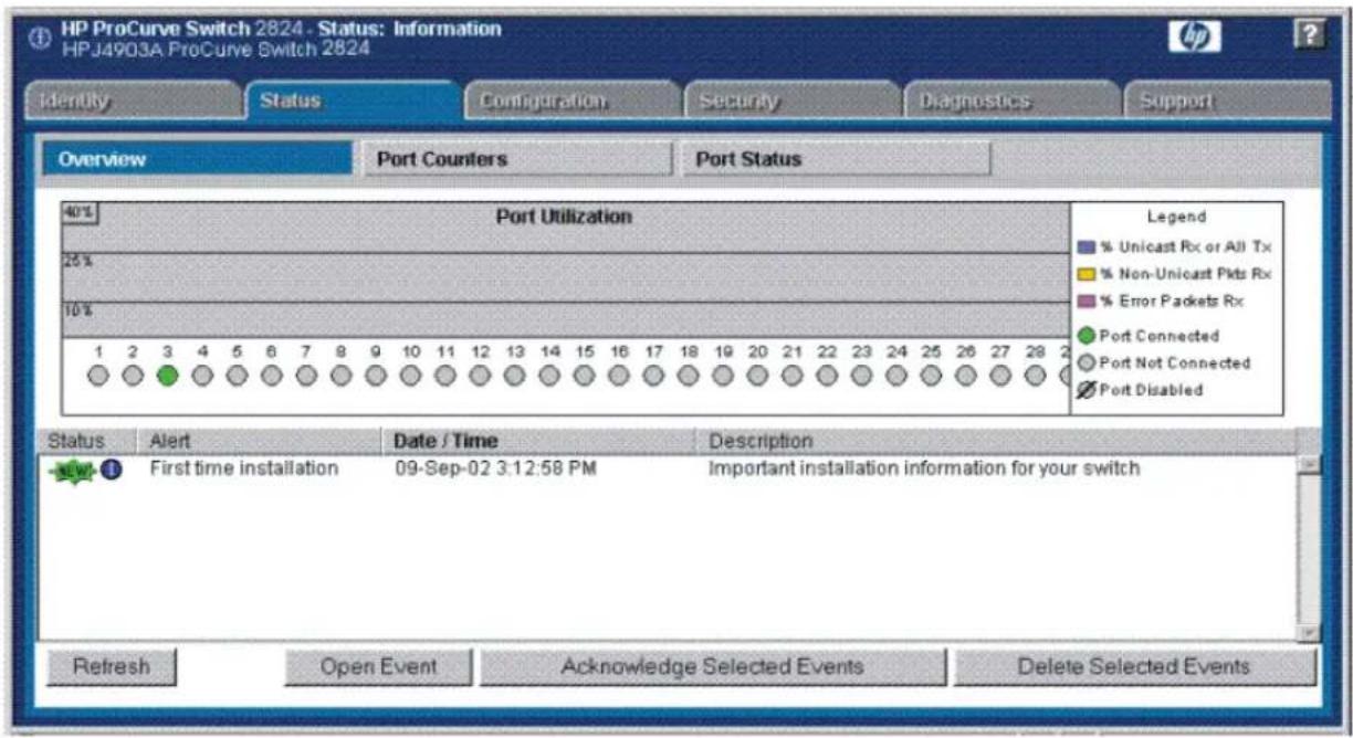
Starting a Web Browser Session
The Switch 2800 Series devices, can be managed through a graphical interface that you can access from any PC or workstation on the network by running your web browser and typing in the switch's IP address as the URL. No additional software installation is required to make this interface available; it is included in the switch's onboard software.
A typical web browser interface screen is shown in the next illustration.
Configuring the Switch
Using the IP Address for Remote Switch Management
For more information on using the web browser interface, please see the Management and Configuration Guide, which is on the Documentation CD-ROM that came with your switch.
An extensive help system is also available for the web browser interface. To access the help system though the subnet on which the switch is installed you must have access to the internet.
Troubleshooting
This chapter describes how to troubleshoot the Switch 2800 Series devices. This document describes troubleshooting mostly from a hardware perspective. You can perform more in-depth troubleshooting on the Switch 2800 Series devices using the software tools available with the switch, including the full-featured console interface, the built-in web browser interface. For more information, see the chapter “Troubleshooting” in the Management and Configuration Guide, which is on the Documentation CD-ROM that came with your switch.
This chapter describes the following:
■ basic troubleshooting tips (page 4-1)
■ diagnosing with the LEDs (page 4-4)
■ Proactive Networking tools (page 4-8)
■ hardware diagnostic tests (page 4-9)
■ restoring the factory default configuration (page 4-11)
■ downloading new software to the Switch 2800 Series devices (page 4-12)
■ HP Customer Support Services (page 4-12)
Basic Troubleshooting Tips
Most problems are caused by the following situations. Check for these items first when starting your troubleshooting:
■Connecting to devices that have a fixed full-duplex configuration.
The RJ-45 ports are configured as “Auto”. That is, when connecting to attached devices, the switch will operate in one of two ways to determine the link speed and the communication mode (half duplex or full duplex):
- If the connected device is also configured to Auto, the switch will automatically negotiate both link speed and communication mode.
- If the connected device has a fixed configuration, for example 100 Mbps, at half or full duplex, the switch will automatically sense the link speed, but will default to a communication mode of half duplex.
Because the Switch 2800 Series devices behave in this way (in compliance with the IEEE 802.3 standard), if a device connected to the switch has a fixed configuration at full duplex, the device will not connect correctly to the switch. The result will be high error rates and very inefficient communications between the switch and the device.
Make sure all devices connected to the Switch 2800 Series devices are configured to auto negotiate, or are configured to connect at half duplex (all hubs are configured this way, for example).
■ Faulty or loose cables. Look for loose or obviously faulty connections. If they appear to be OK, make sure the connections are snug. If that does not correct the problem, try a different cable.
- Non-standard cables. Non-standard and miswired cables may cause network collisions and other network problems, and can seriously impair network performance. Use a new correctly-wired cable or compare your cable to the cable in appendix B, “Twisted-Pair Cable/Connector Pin-Outs” on page 5 for pinouts and correct cable wiring. A category 5 cable tester is a recommended tool for every 100Base-TX and 1000Base-T network installation.
- Improper Network Topologies. It is important to make sure you have a valid network topology. Common topology faults include excessive cable length and excessive repeater delays between end nodes. If you have network problems after recent changes to the network, change back to the previous topology. If you no longer experience the problems, the new topology is probably at fault. Sample topologies are shown at the end of chapter 2 in this book, and some topology configuration guidelines can be found on the HP ProCurve web site, http://www.hp.com/go/hpprocurve.
In addition, you should make sure that your network topology contains no data path loops. Between any two end nodes, there should be only one active cabling path at any time. Data path loops will cause broadcast storms that will severely impact your network performance.
For your Switch 2800 Series devices, if you wish to build redundant paths between important nodes in your network to provide some fault tolerance, you should enable Spanning Tree Protocol support on the switch. This ensures that only one of the redundant paths is active at any time, thus avoiding data path loops. Spanning Tree can be enabled through the switch console or the web browser interface.
The Switch 2800 Series devices also supports Trunking, which allows multiple network cables to be used for a single network connection without causing a data path loop. For more information on Spanning Tree and Trunking, see the Management and Configuration Guide, which is on the Documentation CD-ROM that came with your switch.
- Check the port configuration. A port on your Switch may not be operating as you expect because it has been put into a “blocking” state by Spanning Tree, GVRP (automatic VLANs), or LACP (automatic trunking). (Note that the normal operation of the Spanning Tree, GVRP, and LACP features may put the port in a blocking state.) Or, the port just may have been configured as disabled through software.
Use the switch console to determine the port's configuration and verify that there is not an improper or undesired configuration of any of the switch features that may be affecting the port. For more information, see the Management and Configuration Guide, which is on the Documentation CD-ROM that came with your switch.
For more information on possible network problems and their solutions, refer to the technical note “Troubleshooting LAN Performance and Intermittent Connectivity Problems”, which can be found on the HP ProCurve web site, http://www.hp.com/go/hpprocurve, in the Information Library section.
Diagnosing with the LEDs
Table 3-1 shows LED patterns on the switch and the switch modules that indicate problem conditions.
- Check in the table for the LED pattern you see on your switch.
- Refer to the corresponding diagnostic tip on the next few pages.
Table 4-1. LED Error Indicators
| LED Pattern Indicating Problems | Diagnostic Tips | |||||
| Power Fault RPS Self Test | Fan Status | Port LED (in Link view mode) | ||||
| Off with power cord plugged in | * | 0 | n | * | 1 | |
| On Prolonged On * Prolonged On ** | 2 | |||||
| On Blinking ^ | * | * | B ^ | * | i *n | k 3 |
| On Blinking ^ | * | * | Off | Blinking ^ | * | 4 |
| On Blinking ^ | * | * | B ^ | * | i Blinking ^ | k 5 |
| On | Off | * | Off | * | Off with cable connected | 6 |
| On | Off | * | Off | * | On, but the port is not communicating | 7 |
| On | * Blinking | * | ** | 8 | ||
| * This LED is not important for the diagnosis. ^ The blinking behavior is an on/off cycle once every 1.6 seconds, approximately. | ||||||
Diagnostic Tips:
| Tip Problem Solution | ||
| 1 | The switch is not plugged into an active AC power source, or the switch's power supply may have failed and the EPS/RPS is powering the switch. | 1. Verify the power cord is plugged into an active power source and to the switch. Make sure these connections are snug.2. Is an EPS/RPS device connected to the switch? If so, refer to your EPS/RPS documentation.3. Try power cycling the switch by unplugging and plugging the power cord back in.4. If the Power LED is still not on, verify that the AC power source works by plugging another device into the outlet. Or try plugging the switch into a different outlet or try a different power cord.If the power source and power cord are OK and this condition persists, the switch power supply may have failed. Call your HP-authorized LAN dealer, or use the electronic support services from HP to get assistance. See the Customer Support/Warranty booklet for more information. |
| 2 | A switch hardware failure has occurred. All the LEDs will stay on indefinitely. | Try power cycling the switch. If the fault indication reoccurs, the switch may have failed. Call your HP-authorized LAN dealer, or use the electronic support services from HP to get assistance. See the Customer Support/Warranty booklet for more information. |
| 3 | The switch has experienced a software failure during self test. | 1. Try resetting the switch by pressing the Reset button on the front of the switch, or by power cycling the switch.2. If the fault indication reoccurs, attach a console to the switch (as indicated in chapter 2) and configure it to operate at 9600 baud. Then, reset the switch. Messages should appear on the console screen and in the console log identifying the error condition. You can view the console log at that point by selecting it from the console Main Menu. If necessary to resolve the problem, contact your HP-authorized LAN dealer, or use the electronic support services from HP to get assistance. See the Customer Support/Warranty booklet for more information. |
| 4 | One or more of the switch cooling fans may have failed. | Try disconnecting power from the switch and wait a few moments. Then reconnect the power to the switch and check the LEDs again. If the error indication reoccurs, one or more of the fans has failed. The Switch 2824 has three fans and the Switch 2848 has five fans and may continue to operate under this condition if the ambient temperature does not exceed normal room temperature, but for best operation, the switch should be replaced. Contact your HP-authorized LAN dealer, or use the electronic support services from HP to get assistance. See the Customer Support/Warranty booklet for more information. |
| 5 | The network port for which the LED is blinking has experienced a self test or initialization failure. | Try power cycling the switch. If the fault indication reoccurs, the switch port may have failed. Call your HP-authorized LAN dealer, or use the electronic support services from HP to get assistance. See the Customer Support/Warranty booklet for more information. If the port is a mini-GBIC, verify that it is one of the mini-GBICs supported by the switch. Unsupported mini-GBICs will be identified with this fault condition. The supported mini-GBICs are listed in Chapter 2, “Installing the Switch” on page 2-7. The mini-GBICs are also tested when they are “hot-swapped”—installed or changed while the switch is powered on.To verify the port has failed, try removing and reinstalling the mini-GBIC without having to power off the switch. If the port fault indication reoccurs, you will have to replace the mini-GBIC. |
| continued on the next page | ||
| 6 | The network connection is not working properly. | Try the following procedures:For the indicated port, verify both ends of the cabling, at the switch and the connected device, are connected properly.Verify the connected device and switch are both powered on and operating correctly.Verify you have used the correct cable type for the connection:- For twisted-pair connections to the fixed 10/100/1000 ports, if the port is configured to "Auto" (auto negotiate), either "straight-through" or "crossover" cables can be used because of the switch's Auto MDI/MDI-X feature of the 10/100/1000-T port.Note:If the switch port configuration is changed to one of thefixed configuration options (for example, 100 Mbps/Full Duplex), then the port operates asMDI-X onlyand you must use the correct type of cable for the connection. In general, for connecting an end node (MDI port) to the switch, use "straight-through" cable; for connecting to MDI-X ports on hubs, other switches, and routers, use "crossover" cable.- For fiber-optic connections, verify that the transmit port on the switch is connected to the receive port on the connected device, and the switch receive port is connected to the transmit port on the connected device.For the dual-personality 10/100/1000-T ports, be sure a mini-GBIC is not installed in the associated slot.For 1000Base-T connections, verify that the network cabling complies with the IEEE 802.3ab standard. the cable should be installed according to the ANSI/TIA/EIA-568-A-5 specifications. Cable testing should comply with the stated limitations for Attenuation, Near-End Crosstalk, Far-End Crosstalk, Equal-Level Far-End Crosstalk (ELFEXT), Multiple Disturber ELFEXT, and Return Loss.The cable verification process must include all patch cables from any end devices, including the switch, to any patch panels in the cabling path.Verify that the port has not been disabled through a switch configuration change. You can use the console interface, or, if you have configured an IP address on the switch, use the web browser interface to determine the state of the port and re-enable the port if necessary.Verify the switch port configuration matches the configuration of the attached device. For example, if the switch port is configured as "Auto", the port on the attached device also MUST be configured as "Auto". Depending on the port type, twisted-pair or fiber-optic, if the configurations don't match, the results could be a very unreliable connec-tion, or no link at all.If the other procedures don't resolve the problem, try using a different port or a different cable. |
| 7 | The port may be improperly configured, or the port maybe in a “blocking” state by the normal operation of the Spanning Tree, LACP, or IGMP features. | Use the switch console to see if the port is part of a dynamic trunk (through the LACP feature) or to see if Spanning Tree is enabled on the switch, and to see if the port may have been put into a “blocking” state by those features. The show lacp command displays the port status for the LACP feature; the show spanning-tree command displays the port status for Spanning Tree.Also check the Port Status screen using the show interfaces command to see if the port has been configured as “disabled”.Other switch features that may affect the port operation include VLANs and IGMP. Use the switch console to see how the port is configured for these features.For software troubleshooting tips, see the chapter “Troubleshooting” in the Management and Configuration Guide, which is on the Documentation CD-ROM that came with your switch.Make sure also, that the device at the other end of the connection is indicating a good link to the switch. If it is not, the problem may be with the cabling between the devices or the connectors on the cable. |
| 8 | RPS is connected but has experienced a fault. | Refer to the EPS/RPS documentation. |
Proactive Networking
The HP ProCurve Switch 2800 Series devices have built-in management capabilities that proactively help you manage your network including:
■ finding and helping you fix the most common network error conditions (for example, faulty network cabling, and non-standard network topologies)
■ informing you of the problem with clear, easy-to-understand messages
■recommending network configuration changes to enhance the performance of your network
The following interfaces provide tests, indicators, and an event log that can be used to monitor the switch and its network connections and to help you take advantage of these proactive networking features:
■ A graphical web browser interface that you can use to manage your switch from a PC running a supported web browser, for example Microsoft Internet Explorer, and Netscape Communicator.
A full-featured easy-to-use console interface that you can access by connecting a standard terminal or PC running a terminal emulator to the switch's console port. The cable to make that connection is provided with your switch. The console interface is also accessible through a Telnet connection.
For more information on using these software tools to diagnose and manage your switch, see the “Troubleshooting” chapter in the Management and Configuration Guide, which is on the Documentation CD-ROM that came with your switch.
Hardware Diagnostic Tests
Testing the Switch by Resetting It
If you believe the switch is not operating correctly, you can reset the switch to test its circuitry and operating code. To reset a switch, either:
■Unplug and plug in the power cord (power cycling)
■Press the Reset button on the front of the switch
Power cycling the switch and pressing the Reset button both cause the switch to perform its power-on self test, which almost always will resolve any temporary operational problems. These reset processes also cause any network traffic counters to be reset to zero, and cause the System Up Time timer to reset to zero.
Checking the Switch LEDs
The self test passes if the Fault and Test LEDs on the front of the switch go off after approximately 50 seconds. If these LEDs stay on longer than 60 seconds or begin blinking, there may be a problem with the switch.
See “Diagnosing With the LEDs” on page 4-4 for information on interpreting the LED patterns and LED behaviors in chapter one.
Checking Console Messages
Useful diagnostic messages may be displayed on the console screen when the switch is reset. To connect a PC running a VT-100 terminal emulator program or a standard VT-100 terminal to the switch's Console Port and configure it to run at 9600 baud, and with the other terminal communication settings shown on page 2-22. Then, when you reset the switch, note the messages that are displayed. Additionally, you can check the switch event log, which can be accessed from the console using the show log command, or from the console Main Menu.
Testing Twisted-Pair Cabling
Network cables that fail to provide a link or provide an unreliable link between the switch and the connected network device may not be compatible with the IEEE 802.3 Type 10Base-T, 100Base-TX, or 1000Base-T standards. The twisted-pair cables attached to the Switch must be compatible with the appropriate standards. To verify your cable is compatible with these standards, use a qualified cable test device.
Testing Switch-to-Device Network Communications
You can perform the following communication tests to verify the network is operating correctly between the switch and any connected device that can respond correctly to the communication test.
- Link Test – a physical layer test that sends IEEE 802.2 test packets to any device identified by its MAC address
- Ping Test – a network layer test used on IP networks that sends test packets to any device identified by its IP address
These tests can be performed through the switch console interface from a terminal connected to the switch or through a Telnet connection, or from the switch's web browser interface. For more information, see the Management and Configuration Guide, which is on the Documentation CD-ROM that came with your switch.
Testing End-to-End Network Communications
Both the switch and the cabling can be tested by running an end-to-end communications test -- a test that sends known data from one network device to another through the switch. For example, if you have two PCs on the network that have LAN adapters between which you can run a link-level test or Ping test through the switch, you can use this test to verify that the entire communication path between the two PCs is functioning correctly. See your LAN adapter documentation for more information on running a link test or Ping test.
Restoring the Factory Default Configuration
As part of your troubleshooting process on the Switch, it may become necessary to return the switch configuration to the factory default settings. This process momentarily interrupts the switch operation, clears any passwords, clears the console event log, resets the network counters to zero, performs a complete self test, and reboots the switch into its factory default configuration including deleting the IP address, if one is configured.
Note
This process removes all switch configuration changes you have made from the factory default settings. This includes, for example, configuration of VLANs, Spanning Tree, trunks, and stacking. Returning the configuration of these features to their factory default settings (usually disabling them) may result in network connectivity issues.
If the switch has a valid configuration, and you are restoring the factory default settings for a reason other than configuration problems, you should save the switch configuration prior to performing the factory default reset. Then, after the reset and resolution of the original problem, you can restore the saved configuration to the switch. For both the save and restore processes, you can use the console copy command. For more information on this command, see the Management and Configuration Guide, which is on the Documentation CD-ROM that came with your switch.
You can restore the factory default configuration either on the switch itself, or through the switch console.
To execute the factory default reset on the switch, perform these steps:
- Using pointed objects, simultaneously press both the Reset and Clear buttons on the front of the switch.
- Continue to press the Clear button while releasing the Reset button.
- When the Test LED begins to blink, release the Clear button.
The switch will then complete its self test and begin operating with its configuration restored to the factory default settings.
To restore the factory default configuration using the console, execute the erase startup-config command from the console command prompt.
Downloading New Switch Software
When product enhancements occur for the Switch 2800 Series devices, new software can be downloaded to the switch through several methods, for product enhancements and new features. For more information, see the Management and Configuration Guide, which is on the Documentation CD-ROM that came with your switch.
The new switch software would be available on the HP ProCurve web site, http://www.hp.com/go/hpprocurve.
HP Customer Support Services
If you are still having trouble with your switch, Hewlett-Packard offers support 24 hours a day, seven days a week through the use of a number of automated electronic services. See the Customer Support/Warranty booklet that came with your switch for information on how to use these services to get technical support. The HP ProCurve web site, http://www.hp.com/go/hpprocurve also provides up-to-date support information.
Additionally, your HP-authorized network reseller can provide you with assistance, both with services they offer and with services offered by HP.
Before Calling Support
Before calling your networking dealer or HP Support, to make the support process most efficient, you first should have retrieved the following information:
Information Item Information Location
| product identification, including mini-GBICs | the front of the switch, and on labels on the mini-GBICs |
| details about the switch's status including the software (OS) version, a copy of the switch configuration, a copy of the switch Event Log, and a copy of the switch status and counters information | switch console: show tech command |
| copy of your network topology map, including network addresses assigned to the relevant devices | your network records |
Physical
2824 (J4903A) 2848 (J4904A)
| Width: | 44.3 cm (17.42 in) | 44.3 cm (17.42 in) |
| Depth: | 36.7 cm (14.4 in) | 43.0 cm (16.9 in) |
Height: 4.4 cm (1.73 in) 4.4 cm (1.73 in)
Weight: 4.62 kg (10.20 lbs) 4.88 kg (10.75 lbs)
Electrical
The switch automatically adjusts to any voltage between 100-127 and 200-240 volts and either 50 or 60 Hz.
2824 (J4903A) 2848 (J4904A)
AC voltage: 100/240 volts 100/240 volts
Maximum current: 0.6 A/0.3A 0.8A/0.4A
Frequency range: 50/60 Hz 50/60 Hz
Environmental
| Operating Non-Operating | ||
| Temperature: | 0°C to 55°C (32°F to 131°F) | -40°C to 70°C (-40°F to 158°F) |
| Relative humidity:(non-condensing) | 15% to 95% at 40°C (104°F) | 15% to 90% at 65°C (149°F) |
| Maximum altitude: | 4.6 Km (15,000 ft) | 4.6 Km (15,000 ft) |
Acoustic
Noise Emission LwA=52 dB at virtual workspace according to DIN 45635 T.19
Connectors
■ The 10/100/1000 Mbps RJ-45 twisted-pair ports are compatible with the following standards:
- IEEE 802.3ab 1000Base-T
- IEEE 802.3u 100Base-TX
- IEEE 802.3 10Base-T
The 1000 Mbps LC fiber-optic ports on the Gigabit-SX and Gigabit-LX mini-GBIC transceivers are compatible with the IEEE 802.3z Gigabit-SX and Gigabit-LX standards.
Safety
Complies with:
■EN60950 / IEC 950
■CSA 22.2 No. 950
■UL 60950
Lasers
The Gigabit-SX LC mini-GBIC, and the Gigabit-LX LC mini-GBIC, both of which can be installed in the Switch 2800 Series devices, are Class 1 Laser Products.
Laser Klasse 1
These mini-GBICs comply with IEC 825-2: 1993.
Switch Ports and Network Cables
Note
This appendix includes switch connector information and network cable information for cables that should be used with the Switch 2800 Series devices, including minimum pin-out information and specifications for twisted-pair cables.
Incorrectly wired cabling is the most common cause of problems for LAN communications. HP recommends that you work with a qualified LAN cable installer for assistance with your cabling requirements.
Switch Ports
The fixed RJ-45 10/100/1000Base-T ports on the switch accept 100-ohm unshielded and shielded twisted-pair cable with RJ-45 connectors as described on the next page.
Twisted-Pair Cables
| 10 Mbps Operation | Category 3, 4, or 5 100-ohm unshielded twisted-pair (UTP) or shielded twisted-pair (STP) cable, complying with IEEE 802.3 Type 10Base-T specifications, fitted with RJ-45 connectors |
| 100 Mbps Operation | Category 5 100-ohm UTP or STP cable, complying with IEEE 802.3u 100Base-TX specifications, fitted with RJ-45 connectors |
| 1000 Mbps Operation | Category 5 100-ohm 4-pair UTP or STP cable, complying with IEEE 802.3ab 1000Base-T specifications, fitted with RJ-45 connectors—Category 5E or better is recommended (please see “Note on 1000Base-T Cable Requirements”, below) |
Note on 1000Base-T Cable Requirements. The Category 5 networking cables that work for 100Base-TX connections should also work for 1000Base-T, as long as all four-pairs are connected. But, for the most robust connections you should use cabling that complies with the Category 5E specifications, as described in Addendum 5 to the TIA-568-A standard (ANSI/TIA/EIA-568-A-5).
Because of the increased speed provided by 1000Base-T (Gigabit-T), network cable quality is more important than for either 10Base-T or 100Base-TX. Cabling plants being used to carry 1000Base-T networking must comply with the IEEE 802.3ab standards. In particular, the cabling must pass tests for Attenuation, Near-End Crosstalk (NEXT), and Far-End Crosstalk (FEXT). Additionally, unlike the cables for 100Base-TX, the 1000Base-T cables must pass tests for Equal-Level Far-End Crosstalk (ELFEXT) and Return Loss.
When testing your cabling, be sure to include the patch cables that connect the switch and other end devices to the patch panels on your site. The patch cables are frequently overlooked when testing cable and they must also comply with the cabling standards.
Fiber-Optic
| 1000Base-SX | 62.5/125 μm or 50/125 μm (core/cladding) diameter, graded-index, multimode fiber-optic cables, complying with the ITU-T G.651 and ISO/IEC 793-2 Type A1b or A1a respectively, fitted with LC connectors. |
| 1000Base-LX single mode fiber-optic cables, complying with the ITU-T G.652 and ISO/IEC 793-2 Type B1 standards, fitted with LC connectors OR 62.5/125 μm or 50/125 μm (core/cladding) diameter, graded-index, multimode fiber-optic cables, complying with the ITU-T G.651 and ISO/IEC 793-2 Type A1b or A1a respectively, fitted with LC connectors Note: Multimode fiber-optic cabling may be used for a 1000Base-LX application, but a mode conditioning patch cord may be needed. See “Mode Conditioning Patch Cord for Gigabit-LX” on page B-3 for more information. | |
| 1000Base-LH single mode fiber-optic cables, complying with the ITU-T G.652 and ISO/IEC 793-2 Type B1 standards, fitted with LC connectors |
Mode Conditioning Patch Cord for Gigabit-LX
The following information applies to installations in which multimode fiber-optic cables are connected to a Gigabit-LX port.
Unlike Gigabit-SX, which connects to only multimode fiber-optic cabling, Gigabit-LX can use either single-mode or multimode cable. Multimode cable has a design characteristic called “Differential Mode Delay”, which requires that the transmission signals be “conditioned” to compensate for the cable design and thus prevent resulting transmission errors. Since Gigabit-SX is designed to operate only with multimode cable, Gigabit-SX mini-GBICs can provide that transmission conditioning internally.
Gigabit-LX mini-GBICs, since they are designed to operate with both single-mode and multimode cable, do not provide the transmission conditioning internally. Thus, under certain circumstances, depending on the cable used and the lengths of the cable runs, an external Mode Conditioning Patch Cord may need to be installed between the Gigabit-LX transmitting device and the multimode network cable to provide the transmission conditioning.
If you experience a high number of transmission errors on the Gigabit-LX ports, usually CRC or FCS errors, you may need to install one of these patch cords between the Gigabit-LX port in your switch and your multimode fiber-optic network cabling, and between the Gigabit-LX transmission device and the network cabling at the other end of the multimode fiber-optic cable run. A patch cord must be installed at both ends.
The patch cord consists of a short length of single-mode fiber cable coupled to graded-index multimode fiber cable on the transmit side, and only multi-mode cable on the receive side. The section of single-mode fiber is connected in such a way that it minimizes the effects of the differential mode delay in the multimode cable.
Note
Most of the time, if you are using good quality graded-index multimode fiber cable that adheres to the standards listed on page 2-6, there should not be a need to use mode conditioning patch cords in your network. This is especially true if the fiber runs in your network are relatively short.
If you are using single-mode fiber-optic cabling in your network, there is no need to use mode conditioning patch cords. Connect the single-mode network cable directly to the Gigabit-LX mini-GBIC.
Installing the Patch Cord
As shown in the illustration below, connect the patch cord to the Gigabit-LX mini-GBIC with the section of single-mode fiber plugged in to the Tx (transmit) port. Then, connect the other end of the patch cord to your network cabling patch panel, or directly to the network multimode fiber.
If you connect the patch cord directly to the network cabling, you may need to install a female-to-female adapter to allow the cables to be connected together.
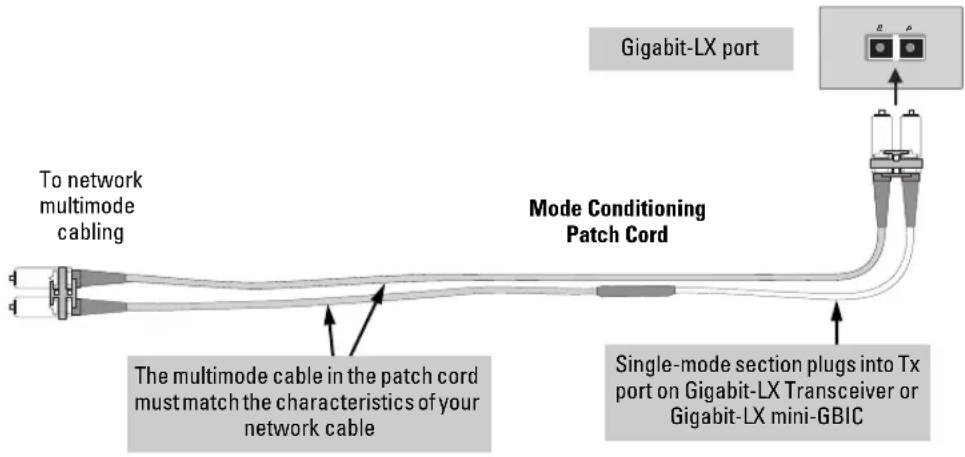
Make sure you purchase a patch cord that has LC connectors on the end that connects to the Gigabit-LX mini-GBIC, and has multimode fibers that match the characteristics of the multimode fiber in your network.
Recommended Patch Cords
Hewlett-Packard maintains a list of recommended Mode Conditioning Patch Cords that have been tested and verified to operate correctly with the HP ProCurve Gigabit-LX Transceiver and HP ProCurve Gigabit-LX LC mini-GBIC.
The list is on the HP ProCurve web site, http://www.hp.com/go/hpprocurve, in the Technical Support section.
Twisted-Pair Cable/Connector Pin-Outs
If you connect a Switch 2800 Series device's twisted-pair port to another switch or hub, which typically have MDI-X ports, the Switch 2800 Series device port automatically operates as an MDI port. If you connect it to an end node, such as a server or PC, which typically have MDI ports, the Switch 2800 Series device's port operates as an MDI-X port. In all cases, you can use standard "straight through" cables or "crossover" cables.
If you happen to use a correctly wired crossover cable, though, the switch will still be able to automatically detect the MDI/MDI-X operation and link correctly to the connected device.
Note
Using Fixed Configurations. If the port configuration is changed to any of the fixed configurations though, for example 100 Mbps/full duplex, the port operates as MDI-X only and the correct cable type must be used: for connections to MDI ports, such as end nodes, use a “straight-through” cable; for connections to MDI-X ports, such as on hubs and other switches, use a “crossover” cable.
Other Wiring Rules:
All twisted-pair wires used for 10 Mbps, and 100 Mbps operation must be twisted through the entire length of the cable. The wiring sequence must conform to EIA/TIA 568-B (not USOC). See “Twisted-Pair Cable Pin Assignments” later in this appendix for a listing of the signals used on each pin.
For 1000Base-T connections, all four pairs of wires in the cable must be available for data transmission. Please see "Note on 1000Base-T Cable Requirements" on page B-1 for more information on 1000Base-T cabling.
■ For 10 Mbps connections to the ports, you can use Category 3, 4, or 5 unshielded twisted-pair cable, as supported by the IEEE 802.3 Type 10Base-T standard.
■ For 100 Mbps connections to the ports, use 100-ohm Category 5 UTP or STP cable only, as supported by the IEEE 802.3u Type 100Base-TX standard.
■ For 1000 Mbps connections, 100-ohm Category 5E or better cabling is recommended.
Straight-Through Twisted-Pair Cable for 10 Mbps or 100 Mbps Network Connections
Because of the MDI/MDI-X operation of the 10/100 ports on the switch, for all network connections, to PCs, servers or other end nodes, or to hubs or other switches, you can use “straight-through” cables.
If any of these ports are given a fixed configuration, for example 100 Mbps/Full Duplex, the ports operate as MDI-X ports, and straight-through cables must be then used for connections to PC NICs and other MDI ports.
Cable Diagram
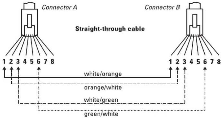
Note
Pins 1 and 2 on connector "A" must be wired as a twisted pair to pins 1 and 2 on connector "B".
Pins 3 and 6 on connector "A" must be wired as a twisted pair to pins 3 and 6 on connector "B".
Pins 4, 5, 7, and 8 are not used in this application, although they may be wired in the cable.
Pin Assignments
Switch End (MDI-X) Computer, Transceiver, or
Other End
| Signal Pins Pins Signal | |||
| receive + | 1 | 1 | transmit + |
| receive - | 2 | 2 | transmit - |
| transmit + | 3 | 3 | receive + |
| transmit - | 6 | 6 | receive - |
Crossover Twisted-Pair Cable for 10 Mbps or 100 Mbps Network Connection
The MDI/MDI-X operation of the 10/100 ports on the switch also allows you to use “crossover” cables for all network connections, to PCs, servers or other end nodes, or to hubs or other switches.
If any of these ports are given a fixed configuration, for example 100 Mbps/Full Duplex, the ports operate as MDI-X ports, and crossover cables must be then used for connections to hubs or switches or other MDI-X network devices.
Cable Diagram
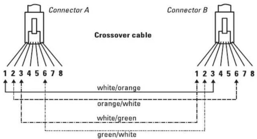
Note
Pins 1 and 2 on connector "A" must be wired as a twisted pair to pins 3 and 6 on connector "B".
Pins 3 and 6 on connector "A" must be wired as a twisted pair to pins 1 and 2 on connector "B".
Pins 4, 5, 7, and 8 are not used in this application, although they may be wired in the cable.
Pin Assignments
Switch End (MDI-X) Hub or Switch Port, or Other
MDI-X Port End
| Signal Pins Pins Signal | |||
| receive + | 1 | 6 | transmit - |
| receive - | 2 | 3 | transmit + |
| transmit + | 3 | 2 | receive - |
| transmit - | 6 | 1 | receive + |
Switch Ports and Network Cables
Twisted-Pair Cable/Connector Pin-Outs
Straight-Through Twisted-Pair Cable for 1000 Mbps Network Connections
1000Base-T connections require that all four pairs of wires be connected.
Cable Diagram
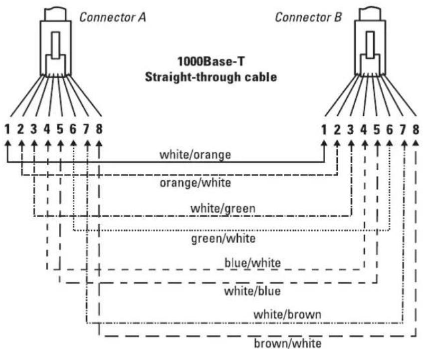
flowchart
graph TD
    A["Connector A"] -->|1 2 3 4 5 6 7 8| B["Connector B"]
    B -->|1 2 3 4 5 6 7 8| A
    A -->|white/orange| C
    B -->|orange/white| C
    A -->|white/green| D
    B -->|green/white| D
    A -->|blue/white| E
    B -->|white/blue| F
    A -->|white/brown| G
    B -->|brown/white| H
Note
Pins 1 and 2 on connector "A" must be wired as a twisted pair to pins 1 and 2 on connector "B".
Pins 3 and 6 on connector "A" must be wired as a twisted pair to pins 3 and 6 on connector "B".
Pins 4 and 5 on connector "A" must be wired as a twisted pair to pins 4 and 5 on connector "B".
Pins 7 and 8 on connector "A" must be wired as a twisted pair to pins 7 and 8 on connector "B".
Pin Assignments
For 1000Base-T operation, all four pairs of wires are used for both transmit and receive.
Safety and EMC Regulatory Statements
Safety Information

Documentation reference symbol. If the product is marked with this symbol, refer to the product documentation to get more information about the product.
WARNING A WARNING in the manual denotes a hazard that can cause injury or death.
CAUTION A CAUTION in the manual denotes a hazard that can damage equipment.
Do not proceed beyond a WARNING or CAUTION notice until you have understood the hazardous conditions and have taken appropriate steps.
Grounding
These are safety class I products and have protective earthing terminals. There must be an uninterruptible safety earth ground from the main power source to the product's input wiring terminals, power cord, or supplied power cord set. Whenever it is likely that the protection has been impaired, disconnect the power cord until the ground has been restored.
For LAN cable grounding:
■ If your LAN covers an area served by more than one power distribution system, be sure their safety grounds are securely interconnected.
■ LAN cables may occasionally be subject to hazardous transient voltages (such as lightning or disturbances in the electrical utilities power grid). Handle exposed metal components of the network with caution.
Servicing
There are no user-serviceable parts inside these products. Any servicing, adjustment, maintenance, or repair must be performed only by service-trained personnel.
These products do not have a power switch; they are powered on when the power cord is plugged in.
Safety Information (Japan)
安全性の考慮
安全記号

EMC Regulatory Statements
U.S.A.
FCC Class A
This equipment has been tested and found to comply with the limits for a Class A digital device, pursuant to Part 15 of the FCC Rules. These limits are designed to provide reasonable protection against interference when the equipment is operated in a commercial environment. This equipment generates, uses, and can radiate radio frequency energy and, if not installed and used in accordance with the instruction manual, may cause interference to radio communications. Operation of this equipment in a residential area may cause interference in which case the user will be required to correct the interference at his own expense.
Canada
This product complies with Class A Canadian EMC requirements.
Australia/New Zealand

This product complies with Australia/New Zealand EMC Class A requirements.
Japan
VCCI Class A
DECLARATION OF CONFORMITY
according to ISO/IEC Guide 22 and EN45014
Manufacturer's Name: Hewlett-Packard Company
Manufacturer's Address: 8000 Foothills Blvd
Roseville, CA 95747-5502
U.S.A.
declares that the product:
Product Name: HP ProCurve Switch 2824,
HP ProCurve Switch 2848
Model Number: J4903A, J4904A
Accessories:
conforms to the following Product Specifications:
Safety: EN60950 (1992) +A1,A2,A3,A4,A11 / IEC 950 (1991) +A1,A2,A3,A4
EN60825-1 (1994) +A11 (1996) / IEC 825-1 (1993), Class 1
EMC: EN 55022 (1998) / CISPR-22 (1997) Class A
EN55024 (1998) / CISPR-24 (1997)
EN 61000-3-2 (2000) / IEC 61000-3-2 (2000)
Harmonics
EN 61000-3-3 (1995) / IEC 61000-3-3 (1994)
Flicker
Supplementary Information:
The product herewith complies with the requirements of the Low Voltage Directive 73/23/EEC and the EMC Directive 89/336/EEC and carries the CE marking accordingly.
Tested with Hewlett-Packard Co. products only.
Roseville, July 31, 2003
Mike Jany
Mike Avery,
Regulatory Engineering Manager
European Contact: Your local Hewlett-Packard Sales and Service Office or Hewlett-Packard GmbH, Department TRE, Herrenberger Strasse 140, D-71034 Böblingen (FAX:+49-7031-14-3143).
Index
Numerics
10/100Base-TX ports
location on switch ... 1-3
1000Base-LH
connections, length limitations ... 2-6
ports, cables used with ... 2-6, B-2
1000Base-LX
connections, length limitations ... 2-6
ports, cables used with ... 2-6, B-2
1000Base-SX
connections, length limitations ... 2-6
ports, cables used with ... 2-6, B-2
1000Base-T
connections, length limitations ... 2-5
ports, cables used with ... 2-5
A
AC power connector
location on back of switch ... 1-9
Act LED ... 1-5, 1-8
auto MDI/MDI-X operation ... B-6, B-8
MDIX feature ... B-5
B
back of switch
description ... 1-9
power connector ... 1-9
backbone switch
topology with ... 2-27
basic switch configuration
IP address ... 3-3
manager password ... 3-2
subnet mask ... 3-3
Switch Setup screen ... 3-2
basic troubleshooting tips ... 4-1
blinking LEDs
error indications ... 4-4
Bootp
automatic switch configuration ... 3-2
for in-band access ... 2-22
buttons
Clear button ... 1-8
LED Mode select button ... 1-7
Reset button ... 1-8
C
cabinet
mounting the switch in ... 2-11
cables
1000Base-LH
connections ... 2-6
fiber-optic cable specifications ... B-2
1000Base-LX
connections ... 2-6
fiber-optic cable specifications ... B-2
1000Base-SX
connections ... 2-6
fiber-optic cable specifications ... B-2
1000Base-T connections ... 2-5
connecting cables to switch ports ... 2-18
effects of non-standard cables ... 4-2
fiber-optic, specifications ... B-2
infrastructure requirements ... 2-5
length limitations ... 2-5
required types ... 2-5
serial, for direct console connection ... 2-23
cables, twisted pair
category 3, 4, 5 ... B-5
cross-over cable pin-out ... B-7
MDI-X to MDI connections ... B-6, B-8
MDI-X to MDI-X connections ... B-7
pin-outs ... B-6, B-8
straight-through cable pin-out ... B-6, B-8
switch-to-computer connection ... B-6, B-8
switch-to-switch or hub connection ... B-7
cables, twisted-pair
MDIX feature ... B-5
wiring rules ... B-5
cables, twisted-pair connector pin-outs ... B-5
cabling infrastructure ... 2-5
Clear button
deleting passwords ... 1-8
description ... 1-8
location on switch ... 1-3, 1-8
restoring factory default configuration ... 1-8, 4-11
to delete password protection ... 3-4
CLI prompt, console
displaying ... 2-23
configuration
checking when troubleshooting ... 4-3
DHCP/Bootp ... 3-2
full duplex only for mini-GBICs ... 2-7
IP address ... 3-3
IP address, manually ... 3-2
manager password ... 3-2
restoring factory defaults ... 1-8, 4-11
subnet mask ... 3-3
Switch Setup screen ... 3-2
connecting the switch to a power source ... 2-17
connecting the switch to an EPS/RPS ... 2-21
connector specifications ... A-2
console
checking messages during troubleshooting ... 4-9
displaying the CLI prompt ... 2-23
features ... 2-22
how to connect in-band ... 2-22
how to connect out-of-band ... 2-22
serial cable connection ... 2-23
Switch Setup screen ... 3-2
Telnet access ... 3-5
terminal configuration ... 2-22
console port
location on switch ... 1-3
cross-over cable
pin-out ... B-7
D
deleting passwords ... 1-8
description
back of switch ... 1-9
front of switch ... 1-3
LEDs ... 1-5
switch ... 1-1
desktop switch
sample topology ... 2-24
DHCP
automatic switch configuration ... 3-2
for in-band access ... 2-22
diagnostic tests ... 4-9
checking the console messages ... 4-9
checking the LEDs ... 4-9
end-to-endconnectivity...4-10
testing the switch only ... 4-9
testing twisted-pair cabling ... 4-10
downloading new switch software ... 4-12
dual-personality ports
LEDs ... 1-6
location on switch ... 1-4
operation description ... 1-4
E
electrical specifications, switch ... A-1
EMC regulatory statements ... C-8
environmental specifications, switch ... A-1
EPS/RPS ... 2-19
cables ... 2-19
connecting to a switch ... 2-21
operation ... 2-21
F
factory default configuration, restoring ... 4-11
factory default configuration,restoring ... 1-8
Fan Status LED ... 1-6
Fault LED ... 1-5
behavior during self test ... 2-11
behaviors ... 1-5
blinking definition ... 1-5-1-6
location on switch ... 1-3
showing error conditions ... 4-4
FDx LED ... 1-5, 1-8
features
console ... 2-22
switch ... 1-10
fiber-optic cables ... B-2
1000Base-LH ... B-2
1000Base-LX ... B-2
1000Base-SX ... B-2
front of switch ... 1-3
10/100Base-TX ports ... 1-3
Clear button ... 1-8
description ... 1-3
dual-personality ports ... 1-4
LED Mode select button and LEDs ... 1-7
LEDs ... 1-5
network ports ... 1-3
Reset button ... 1-8
full-duplex fixed configuration
effects on network connections ... 4-1
full-duplex operation of mini-GBICs ... 2-7
H
horizontal surface
mounting switch on ... 2-17
I
in-band ... 3-1
in-band console access
types of ... 2-22
included parts ... 2-1
installation
connecting the switch to a power source ... 2-17
horizontal surface mounting ... 2-17
location considerations ... 2-6
network cable requirements ... 2-5
precautions ... 2-4
rack or cabinet mounting ... 2-11
site preparation ... 2-5
summary of steps ... 2-3
IP address
configuring ... 3-3
L
LED Mode
indicator LEDs ... 1-7
select button ... 1-7
selecting the display ... 1-7
LEDs
Act ... 1-5, 1-8
behavior during self test ... 2-10
blinking definition ... 1-5-1-6
checking during troubleshooting ... 4-9
descriptions of ... 1-5
dual-personality ports ... 1-6
EPS/RPS ... 2-20
error indications ... 4-4
Fan Status ... 1-6
Fault ... 1-5
behavior during self test ... 2-11
showing error conditions ... 4-4
FDx ... 1-5, 1-8
LED Mode View select indicators ... 1-5
Link ... 1-5
location on switch ... 1-3
Mode
selecting the display ... 1-7
on switch ... 1-5
port
description ... 1-5
Power...1-5
behavior during self test ... 2-11
Self Test ... 1-5
behavior during self test ... 2-10
T and M ... 1-6
length limitations
1000Base-LH connections ... 2-6
1000Base-LX connections ... 2-6
1000Base-SX connections ... 2-6
1000Base-T connections ... 2-5
Link LEDs ... 1-5
link test ... 4-10
location for the switch, considerations ... 2-6
M
MDIX
feature description ... B-5
MDI-X to MDI network cable ... B-6, B-8
MDI-X to MDI-X network cable ... B-7
mini-GBICs
full-duplex operation ... 2-7
slot, location on switch ... 1-3
mounting the switch
in a rack or cabinet ... 2-11
precautions ... 2-4
on a horizontal surface ... 2-17
N
network cables
1000Base-LH connections ... 2-6
1000Base-LX connections ... 2-6
1000Base-SX connections ... 2-6
1000Base-T connections ... 2-5
fiber-optic, specifications ... B-2
MDIX feature ... B-5
required types ... 2-5
twisted-pair connector pin-outs ... B-5
twisted-pair, wiring rules ... B-5
network devices
connecting to the switch ... 2-18
network ports
connecting to ... 2-18
location on switch ... 1-3
standards compliance ... A-2
types of ... 1-3, 2-5
non-standard network cables, effects ... 4-2
0
out-of-band console access ... 3-5
P
parts, included with the switch ... 2-1
password
configuring ... 3-2
passwords
deleting with the Clear button ... 3-4
if you lose the password ... 3-4
passwords, deleting ... 1-8
physical specifications, switch ... A-1
Ping test ... 4-10
pin-outs
twisted-pair cables ... B-5
port configuration
checking when troubleshooting ... 4-3
port LEDs
description ... 1-5
Link ... 1-5
normal operation ... 2-11
T and M ... 1-6
ports
10/100Base-TX, location on switch ... 1-3
connecting to ... 2-18
console ... 2-22
MDIX feature ... B-5
network connections ... 2-18
power connector ... 1-9
Power LED ... 1-5
behavior during self test ... 2-11
behaviors ... 1-5
location on switch ... 1-3
power source
connecting the switch to ... 2-17
precautions
mounting the switch ... 2-4
power requirements ... 2-4
preparing the installation site ... 2-5
Proactive Network tools
diagnostics with ... 4-8
R
rack
mounting precautions ... 2-4
mounting the switch in ... 2-11
Redundant Power Supply ... 2-19
regulatory statements ... C-8
Reset button
description ... 1-8
location on switch ... 1-3, 1-8
restoring factory default configuration ... 4-11
resetting the switch
factory default reset ... 4-11
location of Reset button ... 1-8
troubleshooting procedure ... 4-9
S
safety and regulatory statements ... C-1
safety specifications ... A-2
segment switch
sample topology ... 2-25
selecting the LED Mode display ... 1-7
self test
Fault LED behavior ... 2-11
LED behavior during ... 2-10
Power LED behavior ... 2-11
serial cable
for direct console connection ... 2-23
slots for mini-GBICs
location on switch ... 1-3
specifications
connectors ... A-2
electrical ... A-1
environmental ... A-1
physical ... A-1
safety ... A-2
straight-through cable
pin-out ... B-6, B-8
subnet mask
configuring ... 3-3
summary
of cables used with the switch ... 2-5
of switch installation ... 2-3
switch
connecting to a power source ... 2-17
description ... 1-1
downloading new software ... 4-12
electrical specifications ... A-1
environmental specifications ... A-1
features ... 1-10
front panel description ... 1-3
included parts ... 2-1
LED descriptions ... 1-5
mounting in a rack or cabinet ... 2-11
mounting on horizontal surface ... 2-17
physical specifications ... A-1
switch operation
verifying after installation ... 2-9
Switch Setup screen ... 3-2
configuring a subnet mask ... 3-3
configuring an IP address ... 3-3
field descriptions ... 3-3
T
Telnet access to the console ... 3-5
terminal configuration ... 2-22
Test LED ... 1-5
behavior during factory default reset ... 4-11
behavior during self test ... 2-10
testing
checking the console messages ... 4-9
checking the LEDs ... 4-9
diagnostic tests ... 4-9
end-to-end communications ... 4-10
link test ... 4-10
Ping test ... 4-10
switch operation ... 4-9
switch-to-device communications ... 4-10
twisted-pair cabling ... 4-10
tips for troubleshooting ... 4-1
topologies
samples of ... 2-24
troubleshooting ... 4-1
basic tips ... 4-1
checking port configuration ... 4-3
checking the console messages ... 4-9
checking the LEDs ... 4-9
common network problems ... 4-1
connecting to fixed full-duplex devices ... 4-1
diagnostic tests ... 4-9
effects of non-standard cables ... 4-2
link test ... 4-10
Ping test ... 4-10
Proactive Network tools ... 4-8
restoring factory default configuration ... 4-11
testing connections to other devices ... 4-10
testing end-to-end communications ... 4-10
testing the switch ... 4-9
testing the twisted-pair cables ... 4-10
twisted-pair cable
cross-over cable pin-out ... B-7
pin-outs ... B-5-B-6, B-8
straight-through cable pin-out ... B-6, B-8
switch-to-computer connection ... B-6, B-8
switch-to-switch or hub connection ... B-7
testing ... 4-10
twisted-pair ports
MDIX feature ... B-5
V
VT-100 terminal
serial cable connection for ... 2-23
W
wiring rules for twisted-pair cables ... B-5

Technical information in this document is subject to change without notice.
©Copyright 2002, 2003
Hewlett-Packard Development Company, L.P. Reproduction, adaptation, or translation without prior written permission is prohibited except as allowed under the copyright laws.
Printed in Singapore
August 2003
Manual Part Number
5990-3093


- Publication Number
- Applicable Products
- Trademark Credits
- Disclaimer
- Warranty
- Contents
- Introducing the Switch
- Installing the Switch
- Sample Network Topologies 2-24
- Configuring the Switch
- Using the IP Address for Remote Switch Management ..... 3-5
- Troubleshooting
- Hardware Diagnostic Tests 4-9
- Restoring the Factory Default Configuration 4-11
- A Switch Specifications
- B Switch Ports and Network Cables
- C Safety and EMC Regulatory Statements
- Safety Information (China) C-7
- EMC Regulatory Statements C-8
- Introducing the Switch
- Network Ports
- LEDs
- LED Mode Select Button and Indicator LEDs
- Reset Button
- Clear Button
- Back of the Switch
- Console Port
- Power Connector
- Switch Features
- Installing the Switch
- Included Parts
- Installation Procedures
- Summary
- Installation Precautions:
- Warning
- Cautions
- Prepare the Installation Site
- Installing or Removing mini-GBICs
- Notes
- Caution
- Installing the mini-GBICs:
- Removing the mini-GBICs:
- Note
- Verify the Switch Passes Self Test
- LED Behavior:
- During the self test:
- When the self test completes successfully:
- Mount the Switch
- Rack or Cabinet Mounting
- Warning For safe operation, please read the mounting precautions on page 2-4, before mounting a switch.
- Equipment Cabinet Note
- Rack Mounting the Switch 2848
- Rack Mounting the Switch 2824
- Horizontal Surface Mounting
- Connect the Switch to a Power Source
- Connect the Network Cables
- Using the RJ-45 Connectors
- To connect:
- To disconnect:
- Connecting Cables to mini-GBICs
- (Optional) Connect a Redundant Power Supply to the Switch
- Operating Characteristics
- EPS/RPS Operation
- (Optional) Connect a Console to the Switch
- Terminal Configuration
- Direct Console Access
- HP ProCurve Switch 2848#
- Sample Network Topologies
- As a Desktop Switch
- LEGEND: Gigabit Ethernet cable Fast Ethernet cable
- As a Segment Switch
- LEGEND: — Fast Ethernet cable — Gigabit Ethernet cable — Fiber cable
- Stacking the Switch
- The Switch in a Redundant Topology
- Configuring the Switch
- Recommended Minimal Configuration
- Using the Console Setup Screen
- HP ProCurve Switch 2824#
- Where to Go From Here
- Using the IP Address for Remote Switch Management
- Starting a Telnet Session
- Starting a Web Browser Session
- Troubleshooting
- Basic Troubleshooting Tips
- Diagnosing with the LEDs
- Proactive Networking
- Hardware Diagnostic Tests
- Testing the Switch by Resetting It
- Checking the Switch LEDs
- Checking Console Messages
- Testing Twisted-Pair Cabling
- Testing Switch-to-Device Network Communications
- Testing End-to-End Network Communications
- Restoring the Factory Default Configuration
- Downloading New Switch Software
- HP Customer Support Services
- Before Calling Support
- Physical
- Electrical
- (J4903A) 2848 (J4904A)
- Environmental
- Acoustic
- Connectors
- Safety
- Lasers
- Switch Ports and Network Cables
- Switch Ports
- Mode Conditioning Patch Cord for Gigabit-LX
- Installing the Patch Cord
- Recommended Patch Cords
- Twisted-Pair Cable/Connector Pin-Outs
- Other Wiring Rules:
- Straight-Through Twisted-Pair Cable for 10 Mbps or 100 Mbps Network Connections
- Pin Assignments
- Crossover Twisted-Pair Cable for 10 Mbps or 100 Mbps Network Connection
- Straight-Through Twisted-Pair Cable for 1000 Mbps Network Connections
- Safety and EMC Regulatory Statements
- Safety Information
- Grounding
- Servicing
- Safety Information (Japan)
- EMC Regulatory Statements
- Canada
- Australia/New Zealand
- Japan
- DECLARATION OF CONFORMITY
- Index
- Numerics
- A
- B
- C
- CLI prompt, console
- configuration
- console
- cross-over cable
- D
- description
- desktop switch
- DHCP
- diagnostic tests ... 4-9
- dual-personality ports
- E
- EPS/RPS ... 2-19
- F
- Fan Status LED ... 1-6
- Fault LED ... 1-5
- FDx LED ... 1-5, 1-8
- features
- fiber-optic cables ... B-2
- H
- I
- L
- M
- N
- 0
- P
- R
- S
- T
- V
- W
Brand : HP
Model : ProCurve 2800
Category : Switch