
ProLiant DL120 G5 - Server HP - Free user manual and instructions
Find the device manual for free ProLiant DL120 G5 HP in PDF.


User questions about ProLiant DL120 G5 HP
0 question about this device. Answer the ones you know or ask your own.
Ask a new question about this device
Download the instructions for your Server in PDF format for free! Find your manual ProLiant DL120 G5 - HP and take your electronic device back in hand. On this page are published all the documents necessary for the use of your device. ProLiant DL120 G5 by HP.
USER MANUAL ProLiant DL120 G5 HP
HP ProLiant DL120 Generation 5 Server
Maintenance and Service Guide

Legal notices
© Copyright 2009 Hewlett-Packard Development Company, L.P.
The information contained herein is subject to change without notice. The only warranties for HP products and services are set forth in the express warranty statements accompanying such products and services. Nothing herein should be construed as constituting an additional warranty. HP shall not be liable for technical or editorial errors or omissions contained herein.
Intel, Celeron, Pentium, Xeon, and Intel Core are trademarks of Intel Corporation in the U.S. and other countries.
Microsoft and Windows Server are U.S. registered trademarks of Microsoft Corporation.
Contents
Customer self repair 5
Parts only warranty service.... 5
Illustrated parts catalog....16
Mechanical components 16
System components 21
HP contact information 26
Before you contact HP 26
Removal and replacement procedures 27
Required tools 27
Server warnings and cautions....27
Symbols on equipment....28
Electrostatic discharge information 29
Pre-installation procedure 29
Post-installation procedure 30
Powering down the server....30
Cable management....31
System covers....32
Primary access panel.... 32
Secondary access panel 33
Drive bay configuration 34
System drive cable management 34
Hard disk drive....36
Optical disc drive 42
System board configuration....46
Processor 46
Memory....52
Expansion board 54
System battery 59
Option kits 61
System fans....67
Power supply unit....69
PSU replacement warnings....69
Diagnostic tools 73
HP Insight Diagnostics 73
Array Diagnostic Utility 73
IPMI Event Log....73
Phoenix BIOS software 74
Configuring the system BIOS 74
Setup Utility navigation keys....76
Setup Utility menus....77
Boot-time diagnostic screen 81
Updating/recovering the system BIOS 82
Recording custom Setup values 83
Loading system defaults 84
Clearing CMOS 84
Power-On-Self-Test 85
Connectors, switches, and LEDs 88
Connectors and components 88
Front panel....88
Rear panel 89
System board 90
System buttons and jumpers 91
UID button with LED indicator 91
System jumpers....92
Status LED indicators 93
External LED indicators 93
System board LED indicators 94
System specifications 95
Hardware specifications 95
System unit....95
Memory....96
Processor 97
Power supply unit....100
Software specifications 101
Physical specifications 102
Environmental specifications....103
Index 104
Customer self repair
HP products are designed with many Customer Self Repair (CSR) parts to minimize repair time and allow for greater flexibility in performing defective parts replacement. If during the diagnosis period HP (or HP service providers or service partners) identifies that the repair can be accomplished by the use of a CSR part, HP will ship that part directly to you for replacement. There are two categories of CSR parts:
- Mandatory—Parts for which customer self repair is mandatory. If you request HP to replace these parts, you will be charged for the travel and labor costs of this service.
- Optional—Parts for which customer self repair is optional. These parts are also designed for customer self repair. If, however, you require that HP replace them for you, there may or may not be additional charges, depending on the type of warranty service designated for your product.
NOTE: Some HP parts are not designed for customer self repair. In order to satisfy the customer warranty, HP requires that an authorized service provider replace the part. These parts are identified as "No" in the Illustrated Parts Catalog.
Based on availability and where geography permits, CSR parts will be shipped for next business day delivery. Same day or four-hour delivery may be offered at an additional charge where geography permits. If assistance is required, you can call the HP Technical Support Center and a technician will help you over the telephone. HP specifies in the materials shipped with a replacement CSR part whether a defective part must be returned to HP. In cases where it is required to return the defective part to HP, you must ship the defective part back to HP within a defined period of time, normally five (5) business days. The defective part must be returned with the associated documentation in the provided shipping material. Failure to return the defective part may result in HP billing you for the replacement. With a customer self repair, HP will pay all shipping and part return costs and determine the courier/carrier to be used.
For more information about HP's Customer Self Repair program, contact your local service provider. For the North American program, refer to the HP website (http://www.hp.com/go/selfrepair).
Parts only warranty service
Your HP Limited Warranty may include a parts only warranty service. Under the terms of parts only warranty service, HP will provide replacement parts free of charge.
For parts only warranty service, CSR part replacement is mandatory. If you request HP to replace these parts, you will be charged for the travel and labor costs of this service.
Customer Self Repair
Customer Self Repair
Illustrated parts catalog
Mechanical components
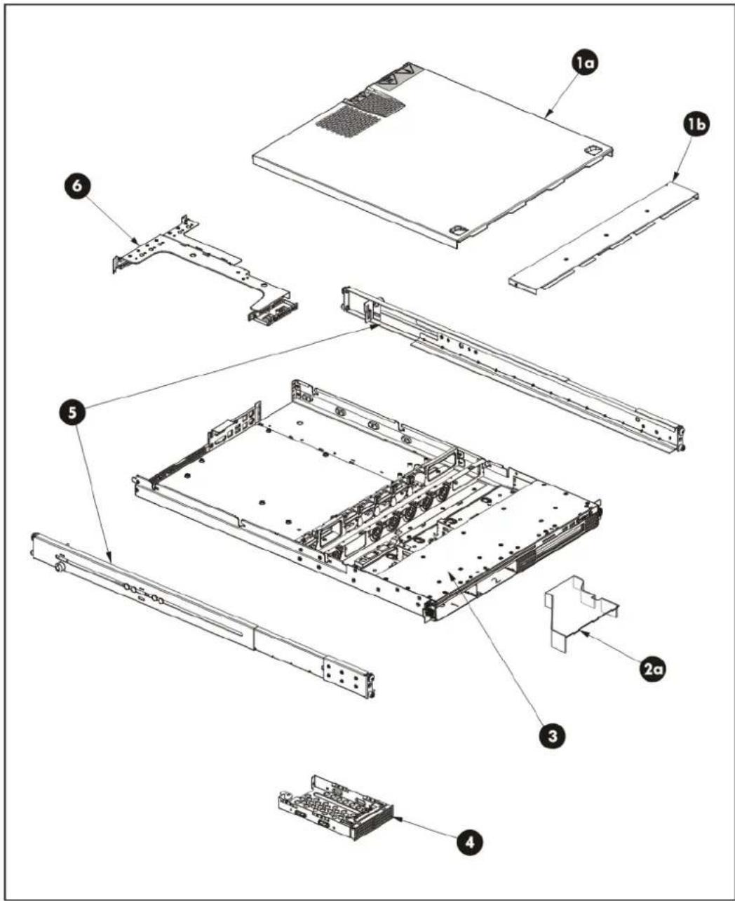
text_image
Exploded view diagram of a server rack system with labeled components including chassis, drive, and chassis modules| Item | Description | Spare | part | number | Customer self repair |
| 1 | Access panel kit 469239-001 | Mandatory | |||
| a) Primary access panel — — | |||||
| b) Secondary access panel — — | |||||
| 2 | Miscellaneous hardware plastic kit 459732-001 | Mandatory | |||
| a) Processor air baffle — — | |||||
| b) Left bezel* — — | |||||
| c) Right bezel* | — | — | |||
| d) Bezel (2-bay media cage model)* | — | — | |||
| e) Foam cable guide* | — | — | |||
| f) Processor backplate* | — | — | |||
| 3 | Two-bay HDD cage | 480510-001 | Mandatory | ||
| 4 | HDD carrier | 460022-001 | Mandatory1 | ||
| 5 | Rack mount rails | 461513-001 | Mandatory | ||
| 6 | PCI module assembly | 458749-001 | Mandatory | ||
* Not shown
^1 Mandatory—Parts for which customer self repair is mandatory. If you request HP to replace these parts, you will be charged for the travel and labor costs of this service.
^2 Optional—Parts for which customer self repair is optional. These parts are also designed for customer self repair. If, however, yo require that HP replace them for you, there may or may not be additional charges, depending on the type of warranty service designated for your product.
^3 No—Some HP parts are not designed for customer self repair. In order to satisfy the customer warranty, HP requires that an authorized service provider replace the part. These parts are identified as "No" in the Illustrated Parts Catalog.
text_image
Exploded view diagram of a computer system with numbered components for identification| Item Description Spare part number Customer self repair | |||
| 1 350-W power supply unit with cable assembly 480507-001 Mandatory | |||
| 2 System fan 457873-001 Mandatory | |||
| 3 ODD backplane board 454515-001 Optional | |||
| Mass storage devices Mandatory | |||
| 4 Optical disc drive (12.7 mm, two-drive model) | |||
| a) SATA DVD-ROM drive 397930-001 | |||
| b) SATA DVD-RW drive 399403-001 | |||
| 5 160-GB non-hot-plug SATA hard drive 373312-001 | |||
| 6 72-GB non-hot-plug SAS hard drive 375874-005 | |||
| System drive cables Mandatory | |||
| 7 SAS LED cable 444692-001 | |||
| 8 SAS HDD cable 457892-001 | |||
| 9 SATA HDD cable 452334-001 | |||
| 10 SATA ODD cable 434462-001 | |||
| 11 Front LED cable 457870-001 | |||
| 12 Front USB port cable 452338-001 | |||
| 13 System board 480508-001 | Optional^2 | ||
| 14 Memory module (PC2-6400 ECC RoHS) Mandatory | |||
| a) 512 MB 459931-001 | |||
| b) 1GB 459932-001 | |||
| c) 2 GB 460424-001 | |||
| 15 Lights-Out 100c remote management card 480902-001 Mandatory | |||
| 16 Processor (include alcohol pad and thermal compound) | Optional^2 | ||
| a) Intel Celeron L420 454523-001 | |||
| b) Intel Celeron L440 454524-001 | |||
| c) Dual-Core Intel Xeon 3065 454525-001 | |||
| d) Dual-Core Intel Xeon 3075 454526-001 | |||
| e) Dual-Core Intel Xeon 3085 454527-001 | |||
| f) Dual-Core Intel Xeon E3110 463509-001 | |||
| g) Dual-Core Intel Xeon E3120 493930-001 | |||
| h) Dual-Core Intel Pentium E2160 455623-001 | |||
| Item | Description | Spare part number | Customer self repair |
| i) | Intel Core 2 Duo E4600 | 484797-001 | |
| j) | Quad-Core Intel Xeon X3210 | 457020-001 | |
| k) | Quad-Core Intel Xeon X3320 | 463508-001 | |
| l) | Quad-Core Intel Xeon X3350 | 463507-001 | |
| m) | Quad-Core Intel Xeon X3330 | 493929-001 | |
| n) | Quad-Core Intel Xeon X3360 | 469858-001 | |
| 17 | Heat sink | 480901-001 | Optional |
| 18 | Full-length/full-height PCI-E x8 riser board | 454512-001 Mandatory | |
| 19 | Low-profile PCI-E x4 riser board | 480509-001 Mandatory | |
^1 Mandatory—Parts for which customer self repair is mandatory. If you request HP to replace these parts, you will be charged for the travel and labor costs of this service.
^2 Optional—Parts for which customer self repair is optional. These parts are also designed for customer self repair. If, however, you require that HP replace them for you, there may or may not be additional charges, depending on the type of warranty service designated for your product.
^3 No—Some HP parts are not designed for customer self repair. In order to satisfy the customer warranty, HP requires that an authorized service provider replace the part. These parts are identified as "No" in the Illustrated Parts Catalog.
^1 Mandatory: Obligatoire—Pièces pour lesquelles la réparation par le client est obligatoire. Si vous demandez à HP de remplacer ces pièces, les coûts de déplacement et main d'œuvre du service vous seront facturés.
^2 Optional: Facultatif—Pièces pour lesquelles la réparation par le client est facultative. Ces pièces sont également conçues pour permettre au client d'effectuer lui-même la réparation. Toutefois, si vous demandez à HP de remplacer ces pièces, l'intervention peut ou non vous être facturée, selon le type de garantie applicable à votre produit.
^3 No: Non—Certaines pièces HP ne sont pas conçues pour permettre au client d'effectuer lui-même la réparation. Pour que la garantie puisse s'appliquer, HP exige que le remplacement de la pièce soit effectué par un Mainteneur Agréé. Ces pièces sont identifiées par la mention "Non" dans le Catalogue illustré.
^1 Mandatory: Obbligatorie—Parti che devono essere necessariamente riparate dal cliente. Se il cliente ne affida la riparazione ad HP, deve sostenere le spese di spedizione e di manodopera per il servizio.
^2 Optional: Opzionali—Parti la cui riparazione da parte del cliente è facoltativa. Si tratta comunque di componenti progettati per questo scopo. Se tuttavia il cliente ne richiede la sostituzione ad HP, potrebbe dover sostenere spese addizionali a seconda del tipo di garanzia previsto per il prodotto.
^3 No: Non CSR—Alcuni componenti HP non sono progettati per la riparazione da parte del cliente. Per rispettare la garanzia, HP richiede che queste parti siano sostituite da un centro di assistenza autorizzato. Tali parti sono identificate da un “No” nel Catalogo illustrato dei componenti.
For the name of the nearest HP authorized reseller:
• In the United States, call 1-800-345-1518.
• In Canada, call 1-800-263-5868.
• In other locations, refer to the HP website at www.hp.com.
For HP technical support:
• In North America:
○ Call 1-800-HP-INVENT (1-800-474-6836). This service is available 24 hours a day, 7 days a week. For continuous quality improvement, calls may be recorded or monitored.
If you have purchased a Care Pack (service upgrade), call 1-800-633-3600. For more information about Care Packs, refer to the HP website at www.hp.com.
- Outside North America, call the nearest HP Technical Support Phone Center. For telephone numbers of worldwide Technical Support Centers, refer to the HP website at www.hp.com.
Before you contact HP
Be sure to have the following information available before you call HP:
• Technical support registration number (if applicable)
• Product serial number (printed on the serial pull tab located on the front panel)
• Product model name and number
• Applicable error messages
- Add-on boards or hardware
• Third-party hardware or software
- Operating system type and revision level
Removal and replacement procedures
Required tools
In performing any hardware configuration procedure you may need the following tools:
- System screwdriver (secured to the rear panel)
With the exception of the ODD module mounting screws, all hardware screws used in the server can be removed or tightened by using the system screwdriver. - Flat-blade M2.5 screwdriver for ODD configuration
The following references and software tools may also be used:
• HP ProLiant DL120 Generation 5 Server Support CD
- IPMI Event Log
• Diagnostics software
Server warnings and cautions
Before installing a server, be sure that you understand the following warnings and cautions.
⚠ WARNING: To reduce the risk of personal injury from hot surfaces, allow the drives and the internal system components to cool before touching them.
△ CAUTION: The server must always be operated with the system covers on. Proper cooling is not achieved when the system covers are removed.
CAUTION: Whenever installing hardware or performing maintenance procedures requiring access to internal components, it is recommended that users first back up all server data to avoid loss.
IMPORTANT: Before removing any serviceable parts, determine whether the part is hot-plug or non-hot-plug. If the device is non-hot-plug, you must power down the server. Non-hot-plug devices in the server include the processor, all boards, memory modules, fans, expansion boards, and all system drives.
IMPORTANT: Review the specifications of a new component before installing it to make sure it is compatible with the server. When you integrate new components into the system, record its model and serial number, and any other pertinent information for future reference. After completing any removal or replacement procedure, run the diagnostics program to verify that all components operate properly.
Symbols on equipment
The following symbols may be placed on equipment to indicate the presence of potentially hazardous conditions:
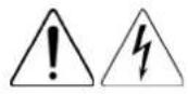
This symbol indicates the presence of hazardous energy circuits or electric shock hazards. Refer all servicing to qualified personnel.

WARNING: To reduce the risk of injury from electric shock hazards, do not open this enclosure. Refer all maintenance, upgrades, and servicing to qualified personnel.
This symbol indicates the presence of electric shock hazards. The area contains no user or field serviceable parts. Do not open for any reason.
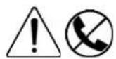
WARNING: To reduce the risk of injury from electric shock hazards, do not open this enclosure.
This symbol on an RJ-45 receptacle indicates a network interface connection.
WARNING: To reduce the risk of electric shock, fire, or damage to the equipment, do not plug telephone or telecommunications connectors into this receptacle.

This symbol indicates the presence of a hot surface or a hot component. If this surface is touched, the potential for injury exists.
WARNING: To reduce the risk of injury from a hot component, allow the surface to cool before touching.
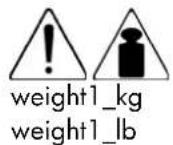
This symbol indicates that the component exceeds the recommended weight for one individual to handle safely.
WARNING: To reduce the risk of personal injury or damage to the equipment, observe local occupational health and safety requirements and guidelines for manual material handling.
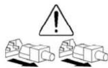
These symbols, on power supplies or systems, indicate that the equipment is supplied by multiple sources of power.
WARNING: To reduce the risk of injury from electric shock, remove all power cords to completely disconnect power from the system.
Electrostatic discharge information
An electrostatic discharge (ESD) can damage static-sensitive devices or microcircuitry. Proper packaging and grounding techniques are necessary precautions to prevent damage. To prevent electrostatic damage, observe the following precautions:
- Transport products in static-safe containers such as conductive tubes, bags, or boxes.
- Keep electrostatic-sensitive parts in their containers until they arrive at static-free stations.
- Cover workstations with approved static-dissipating material. Use a wrist strap connected to the work surface, and properly grounded (earthed) tools and equipment.
- Keep work area free of nonconductive materials, such as ordinary plastic assembly aids and foam packing.
- Make sure that you are always properly grounded (earthed) when touching a static-sensitive component or assembly.
- Avoid touching pins, leads, or circuitry.
• Always place drives with the Printed Circuit Board (PCB) assembly-side down. - Use conductive field service tools.
Pre-installation procedure
Perform the steps below before you open the server or before you remove or replace any component.
- Perform data backup.
- Turn off the server and all the peripherals connected to it.
- Unplug all cables from the power outlets to avoid exposure to high energy levels that may cause burns when parts are short circuited by metal objects such as tools or jewelry. If necessary, label each cable to expedite reassembly.
- Disconnect all telecommunication cables to avoid exposure to shock hazard from ringing voltages.
- Open the server according to the instructions described in the "System covers" section later in this chapter.
- Follow the ESD precautions listed previously in this chapter when handling any hardware component.

IMPORTANT: To streamline the configuration process, read through the entire installation/removal procedure first and make sure you understand it before you begin.
Post-installation procedure
Perform the steps below after installing or removing a server component.
- Be sure all components are installed according to the described step-by-step instructions.
- Check to make sure you have not left loose tools or parts inside the server.
- Reinstall any expansion board, peripheral, and system cables that have previously been removed.
△ CAUTION: Do not operate the server for more than ten minutes with the access panel and disk drives removed. Otherwise, improper cooling airflow may damage the system components.
- Reinstall the system covers.
- Connect all external cables and the AC power cord to the system.
- Press the power button ⏻ on the front panel to turn on the server.
Powering down the server
The server does not completely power down when the power button ⏻ is pressed. The button toggles between On and Standby. The standby position removes power from most electronics and the drives, but some internal circuitry remains active. To completely remove all power from the system, disconnect all power cords from the server.
WARNING: Hazardous voltages are present inside the server. Always disconnect AC power from the server and other associated assemblies while working inside the unit. Serious injury may result if this warning is not observed.
WARNING: To reduce the risk of electric shock or damage to the equipment:
- Do not disable the power cord grounding plug. The grounding plug is an important safety feature.
- Plug the power cord into a grounded (earthed) electrical outlet that is easily accessible at all times.
- Unplug the power cord from the power supply to disconnect power to the equipment.
- Do not route the power cord where it can be walked on or pinched by items placed against it. Pay particular attention to the plug, electrical outlet, and the point where the cord extends from the server.
CAUTION: Protect the server from power fluctuations and temporary interruptions with a regulating uninterruptible power supply (UPS). This device protects the hardware from damage caused by power surges and voltage spikes, and keeps the system in operation during a power failure.
- Shut down the server as directed by the operating system documentation.
- Press the power button ⏻ to toggle to Standby.
This places the server in standby mode changing the power LED indicator to amber. In this mode, the main power supply output is disabled. Standby does not completely disable or remove power from the system. - Disconnect the AC power cord from the AC outlet and then from the server.
- Check that the power LED indicator is turned off and that the fan noise has stopped.
- Disconnect all external peripheral devices from the server.
Cable management
Always follow good cable management practices when working inside the computer.
- Keep cables away from major heat sources like the heat sink.
- Do not jam cables on top of expansion cards or memory modules. Printed circuit cards are not designed to withstand excessive pressure.
- Keep cables clear of sliding or moveable parts to prevent cutting or crimping.
- When folding a flat ribbon cable, never fold to a sharp crease. Sharp creases may damage the wires.
• Some flat ribbon cables come prefolded. Never change the folds on these cables. - Do not sharply bend any cable. A sharp bend can break the internal wires.
- Never bend a SATA data cable tighter than a 30 mm (1.18 in.) radius.
- Never crease a SATA data cable.
- Do not rely on components like the drive cage, power supply, or system cover to push cables down into the chassis.
To disconnect a power supply cable from the system board:
△
CAUTION: Always pull the connector. NEVER pull on the cable. Pulling on the cable can damage the cable and result in a failed power supply.
- Squeeze on the top of the retaining latch attached to the cable end of the connector.
- Grasp the cable end of the connector and pull it straight up.

text_image
Technical diagram showing cable routing setup with labeled components and directional arrows indicating connection pathsSystem covers
Primary access panel
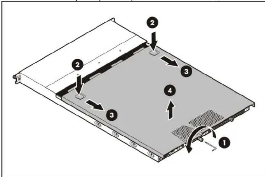
The main chassis area is protected by the primary access panel. This panel must be removed to access the internal components and the system board cable connections of the system drives.
To remove the primary access panel:
-
Perform steps 1 through 4 of the pre-installation procedure.
-
Remove the primary access panel.
a. Loosen the primary access panel thumbscrew (1).
b. Press the panel's release indentations (2) and push backward to release the panel from the chassis (3).
c. Remove the primary access panel from the chassis (4).
text_image
Diagram of a server rack with numbered components and directional arrows indicating assembly or movement.- Place the primary access panel in a safe place for reinstallation later.
Secondary access panel
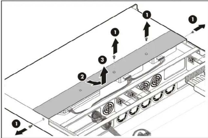
The signal and power cable connections of the system drives are shielded by the secondary access panel. This panel must be removed when configuring the system drives.
To remove the secondary access panel:
-
Remove the primary access panel.
-
Remove the secondary access panel.
a. Remove the four screws that secure the panel (1). Keep these screws for later reinstallation.
b. Slide the panel backward to release it from the chassis (2).
c. Remove the secondary access panel from the chassis (3).
text_image
Technical diagram showing labeled components of a server rack with numbered parts and directional arrows indicating assembly or movement.- Place the secondary access panel in a safe place for reinstallation later.
Drive bay configuration
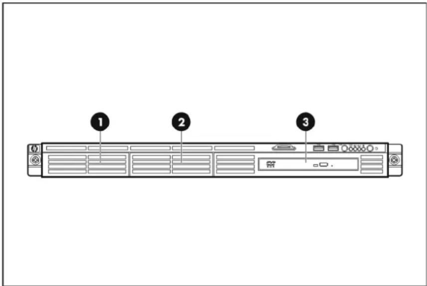
The server supports three drive bays—two drive bays for 1-inch non-hot-plug SAS or SATA hard disk drives (HDD) and one drive bay for a slim type SATA optical disc drive (ODD).
Go to the HP website at www.hp.com and refer to the options list for this server model for the latest information on supported system drives.
text_image
Diagram of a server rack with labeled ports and indicators, showing three numbered positions.| Item | Description |
| 1 | Hard disk drive 1 |
| 2 | Hard disk drive 2 |
| 3 | Optical disc drive |
NOTE: The server does not support SAS and SATA HDD models at the same time.
System drive cable management
The figures in this section illustrate the system drives' data and power cable connections. Observe the proper cable management guidelines described on page 31 when routing the cables.
SATA SKU data cable management
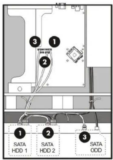
text_image
SATA HDD 1 SATA HDD 2 SATA ODDItem Description HP part number
1 - 2 SATA HDD cables 448180-001
3 SATA ODD cable 433434-001
SAS SKU data cable management
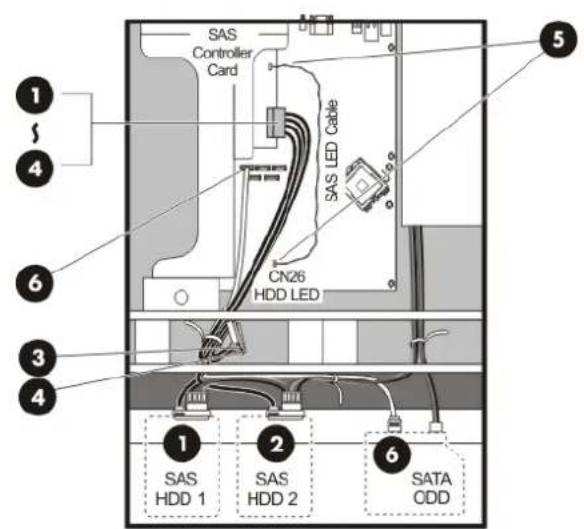
text_image
SAS Controller Card CN26 HDD LED SAS LED Cable 1 2 3 4 5 6 SAS HDD 1 SAS HDD 2 SATA ODDItem Description HP part number
1-4 SAS HDD cable 451375-001
5 SAS LED cable 438884-001
6 SATA ODD cable 433434-001
Power cable management
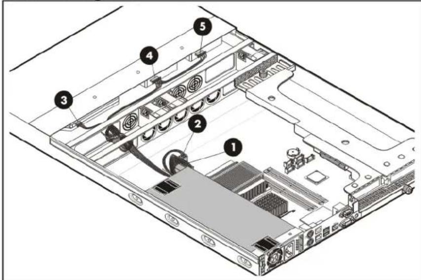
text_image
Technical diagram of an internal server rack with numbered components for identification| Item | PSU cable label | Connects to |
| 1 | P1 PWR_CN on the system board | |
| 2 | P2 CN4 on the system board | |
| 3 | P3 Optical disc drive | |
| 4 | P8 | 2^nd hard drive |
| 5 | P9 | 1^st hard drive |
Hard disk drive
Hard drives installed in the server are labeled as HDD 1 and HDD 2, from left to right, when viewed from the front of the server.
The drive bays can accommodate large form factor (LFF) non-hot-plug SAS or SATA hard drives. The following drive capacities are supported.
• Non-hot-plug SAS HDD - 72-, 146-, and 300-GB
• Non-hot-plug SATA HDD - 80-, 160-, 250-, 500-, and 750-GB

IMPORTANT: SAS hard drives require that you first install the SAS controller board and SAS HDD/LED cable option kits. For instructions on how to install these option kits, go to page 61.
Guidelines for installing hard drives
- Install only hard drive models specified for your ProLiant server. Installing unsupported hard drives may damage the system by consuming power and generating heat in excess of the server's operating tolerance. This condition may result in a loss of system and/or data integrity.
- When installing an additional hard drive (HDD 2), use the HDD 2 drive carrier. This carrier has five pre-installed HDD mounting screws.
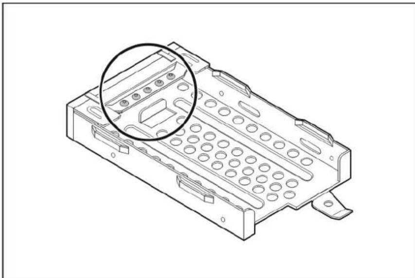
natural_image
Technical line drawing of a mechanical housing component with a magnified inset showing internal slots and mounting brackets (no text or symbols)- If you removed the HDD 2 without plans of installing a new one, you must reinstall the mounting screws to the blank HDD carrier, and then reinstall the carrier in the chassis for proper cooling of the system.
To install a hard drive:
-
Remove the primary and secondary access panels.
-
If you intend to replace the default HDD 1, proceed to step 3.
If you intend to install an additional hard drive in the HDD 2 bay, proceed to step 4.
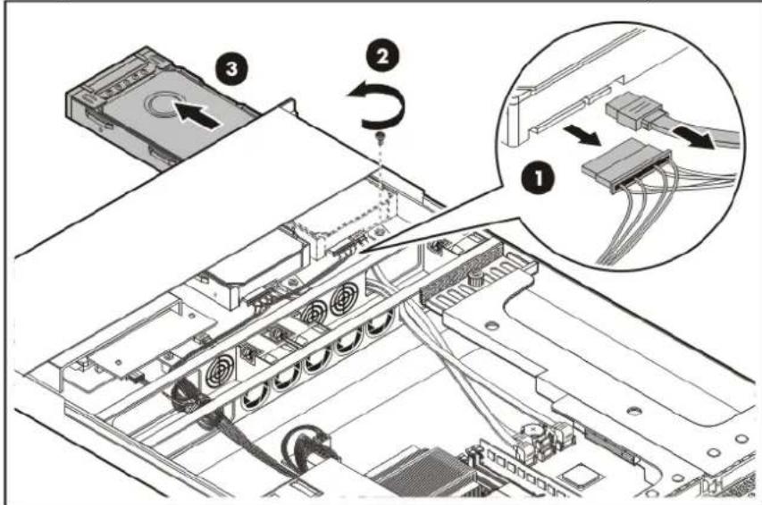
- Remove the default HDD 1 module.
a. Disconnect the data and power cables from the rear of the hard drive (1).
b. Remove the screw that secures the HDD 1 carrier (2).
Reuse this screw when you install the new hard drive.
c. Push the HDD 1 carrier towards the front of the chassis, and then slide it out completely (3).
text_image
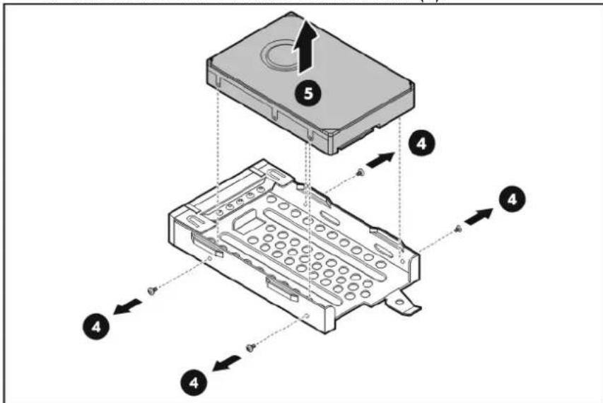
Technical diagram showing server rack with labeled components and wiring connections, including a zoomed-in view of internal cable routing.d. Remove the four mounting screws that secure the HDD 1 module to its carrier (4). Reuse these screws when you install the new hard drive.
e. Remove the HDD 1 module from its carrier (5).
text_image
Technical diagram of a hard disk drive assembly with numbered components and directional arrows indicating assembly steps.f. Place the old hard drive on a static-dissipating work surface or inside an anti-static bag.
g. Proceed to step 5 for instructions on how to install the new hard drive module.
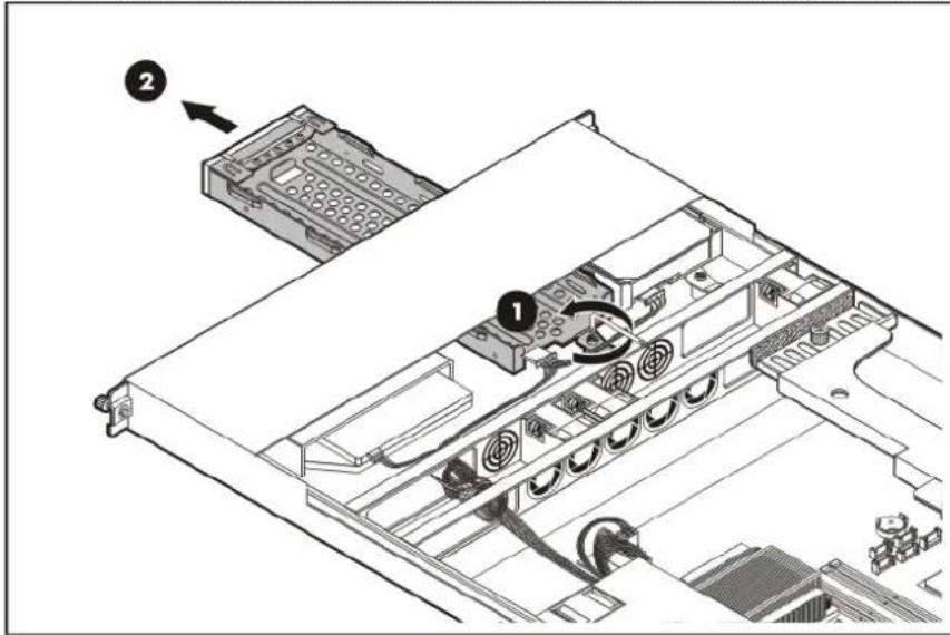
- Remove the HDD 2 drive carrier.
a. Remove the screw that secures the HDD 2 carrier (1).
b. Push the HDD 2 carrier towards the front of the chassis, and then slide it out completely (2)
text_image
Technical diagram of an electronic device showing internal components and a labeled connection point (2)c. Remove four of the five mounting screws from the carrier.
-
Remove the new hard drive from its protective packaging.
-
Install the new hard drive module in its carrier.
a. Align the hard drive module on the carrier (1).
b. Secure the hard drive assembly with four mounting screws (2).

text_image
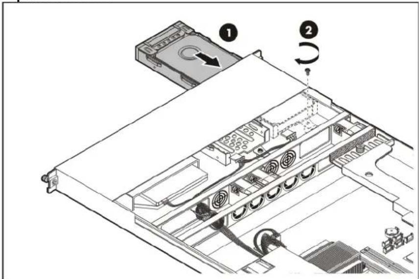
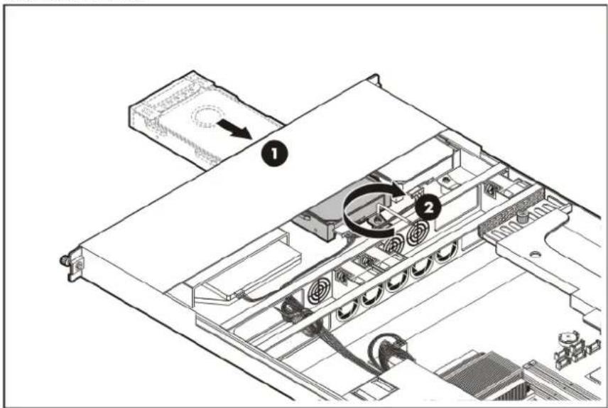
Diagram of an electronic device showing internal components with numbered labels and directional arrows indicating assembly or movement.- Install the new hard drive assembly in the chassis.
a. Slide the hard drive assembly into the chassis (1).
b. Secure the drive carrier with one screw (2).
Replacement HDD 1
text_image
Technical diagram of an electronic device showing internal components and labeled parts, with numbered annotations 1 and 2 indicating specific locations.Additional HDD 2
text_image
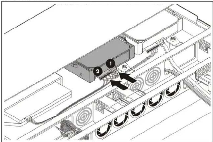
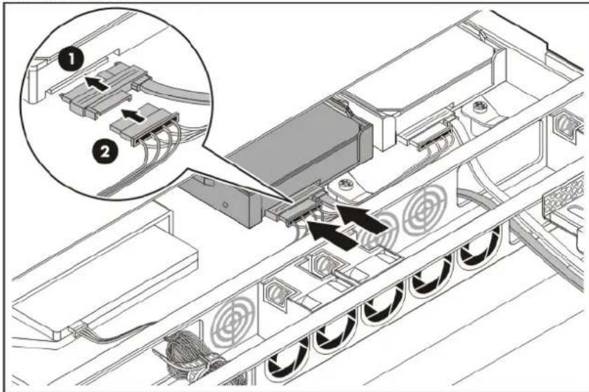
Technical diagram of an electronic device showing internal components with numbered labels and directional arrows indicating flow or movement.- Connect the appropriate data (1) and power (2) cables to the new hard drive.
SATA HDD model
text_image
Technical diagram showing a device with labeled components and directional arrows indicating assembly or connection.SAS HDD model
text_image
Technical diagram showing assembly of a device with labeled components and directional arrows indicating flow or movement.- Perform the post-installation procedure.
Optical disc drive
The server has a default slim-type 12.7 mm SATA optical disc drive. You can choose to replace this default ODD with another model. The following SATA ODD models are supported:
- DVD drive
- DVD-RW drive
Guidelines for installing an optical disc drive
- Install only ODD models specified for your ProLiant server. Installing unsupported ODDs may damage the system by consuming power and generating heat in excess of the server's operating tolerance. This condition may result in a loss of system and/or data integrity.
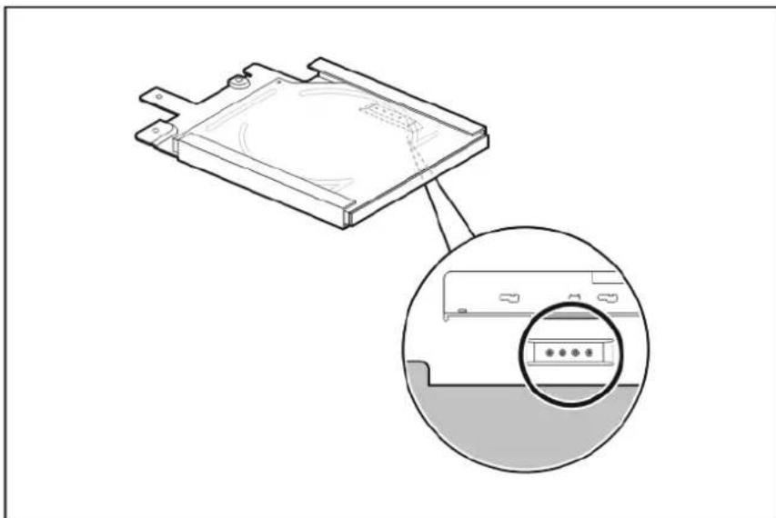
• The ODD carrier has one pre-installed ODD mounting screw located beneath it.
natural_image
Technical line drawing of a device component with an inset magnified view showing internal components (no text or symbols)- If you removed the default ODD without plans of replacing it, you must perform the following procedure to maintain proper system cooling:
a. Reinstall the mounting screws you removed from the ODD module to the ODD carrier.
b. Reinstall the carrier in the chassis.
c. Cover the ODD bay with the ODD bay bezel (purchased separately).
- You will need a flat-blade M2.5 screwdriver to remove the default ODD module from its carrier.
To replace the default optical disc drive:
-
Remove the primary and secondary access panels.
-
Remove the default optical disc drive from the chassis.
a. Disconnect the data and power cables from the ODD (1). b. Remove the screw that secures the ODD carrier (2). Reuse these screws when you install the new ODD.
c. Push the ODD carrier towards the front of the chassis, and then slide it out completely (3).
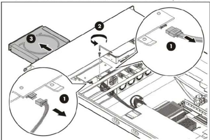
text_image
Technical diagram showing three steps of a server rack with labeled components and cable routing instructions- Remove the ODD backplane board.
a. Remove the two screws that secure the ODD backplane board (1).
b. Detach the backplane board from the ODD module (2).
Reuse this backplane board when you install the new ODD.
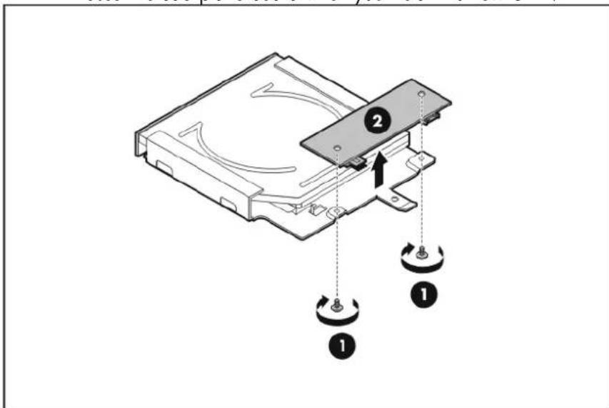
text_image
Diagram of a computer drive with labeled components and rotation arrows- Remove the default optical disc drive from its carrier.
a. Use a flat-blade M2.5 screwdriver to remove the four mounting screws that secure the ODD module to its carrier (1).
Reuse these screws when you install the new ODD.
b. Remove the default ODD module from its carrier (2).
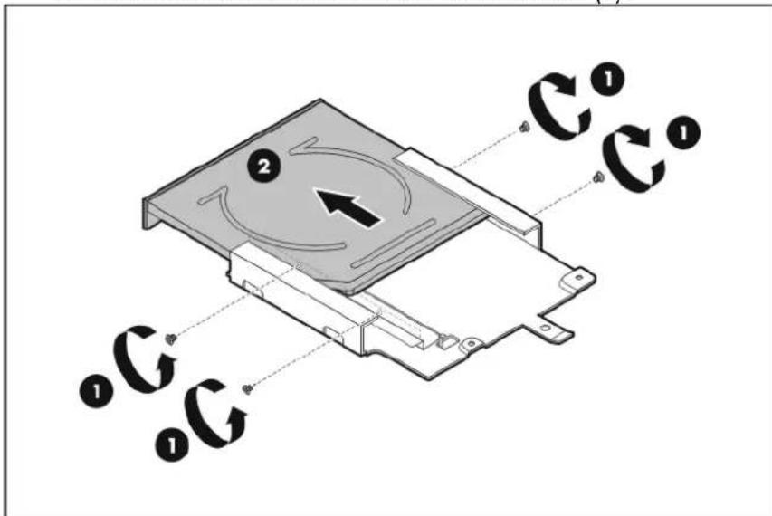
text_image
Diagram of a device with labeled components and circular arrows indicating rotation or flow direction.c. Place the old ODD module on a static-dissipating work surface or inside an anti-static bag.
-
Remove the new ODD module from its protective packaging.
-
Install the new ODD module in its carrier.
a. Align the ODD module on the carrier (1).
b. Secure the ODD assembly with four mounting screws (2).
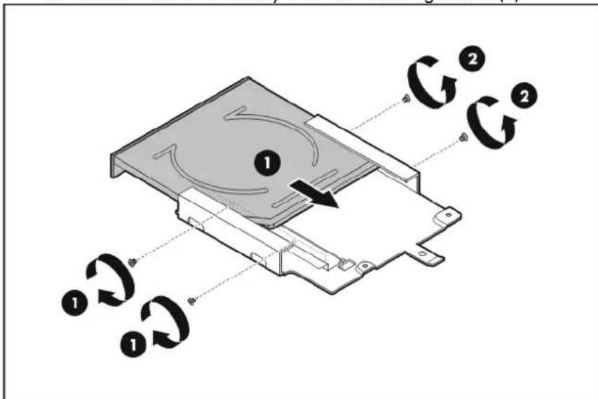
text_image
Diagram of a device with labeled components and circular arrows indicating rotation or movement paths.- Reinstall the ODD backplane board.
a. Connect the backplane board to the new ODD module (1).
b. Secure the backplane board to the ODD carrier with two screws removed (2).
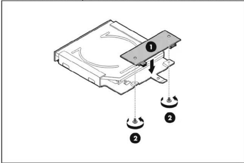
text_image
Diagram of a computer drive with labeled components and directional arrows indicating motion or assembly.- Install the new ODD assembly in the chassis.
a. Slide the ODD assembly into the chassis (1).
b. Secure the ODD carrier with two screws (2).
c. Connect the data and power cables to the new optical disc drive (3).
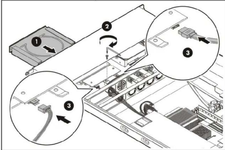
text_image
Technical diagram showing three steps of a computer drive assembly with labeled components and cable connections- Perform the post-installation procedure.
System board configuration
Refer to the following sections for instructions about how to remove or replace the processor, the memory modules, the expansion cards, and the system battery. Procedures for installing the SAS controller board, PCI-X riser board, and Lights-Out 100c remote management card option kits are also provided.
Processor
The system processor socket supports several Intel processor models. Go to page 97 for the list of supported processor models and their specifications.
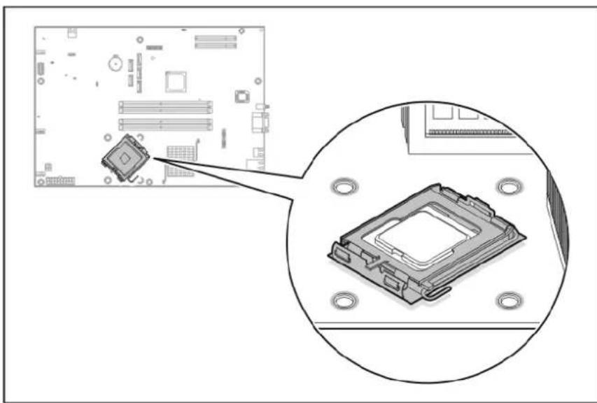
natural_image
Diagram showing a computer motherboard with an inset close-up of the chip and mounting holes (no text or symbols)Processor installation guidelines
When configuring the processor, observe the following important guidelines:
- Handle the processor and heat sink with care. Damage to either may prevent the system from functioning properly.
- Never touch the bottom surface of the processor or the contact pins on the processor socket; contaminant on these areas can damage the processor.
- Be sure that the server has the most recent ROM version. Failure to flash the ROM before installing processors can cause system failure.
Processor installation
⚠ WARNING: To reduce the risk of personal injury from hot surfaces, allow the heat sink and the processor to cool before touching them.
CAUTION: To prevent the heat sink from tilting to one side during installation/removal procedures, observe a diagonally opposite pattern (an "X" pattern) when loosening and tightening the four spring loaded screws.
The procedure for replacing the current processor consists of five major steps which are as follows:
- Remove the heat sink.
- Remove the current processor.
- Apply the thermal compound.
- Install the new processor.
- Install the heat sink.
To remove the heat sink:
- Prior to removing the heat sink, power on the system for a few minutes to soften the thermal compound, so that the heat sink can easily be removed.
- Perform the pre-installation procedure.
- Remove the air baffle.
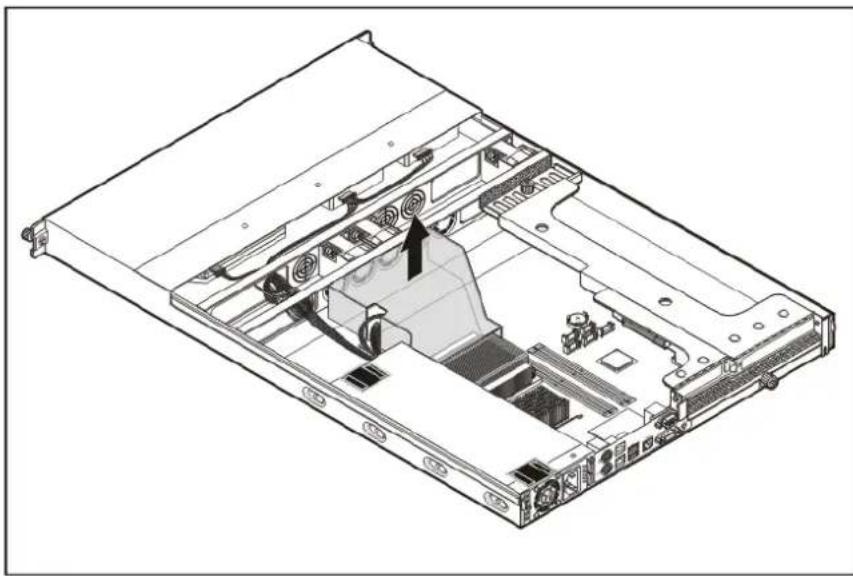
natural_image
Technical line drawing of an internal server or chassis with visible circuitry and ventilation (no text or symbols)- Remove the heat sink.
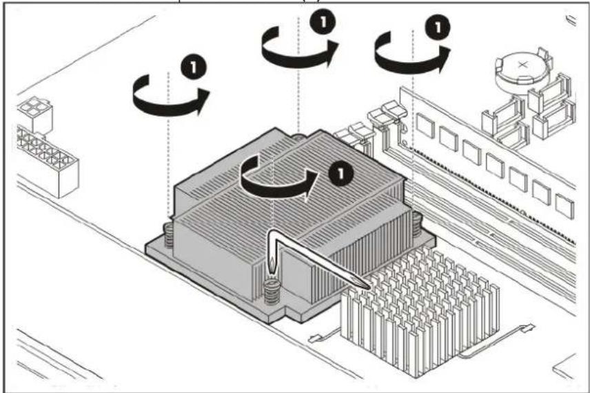
a. Use the system screwdriver to loosen the four spring-loaded screws a few threads out, observing a diagonally opposite pattern, and then loosen them completely to release the heat sink from the processor base (1).
text_image
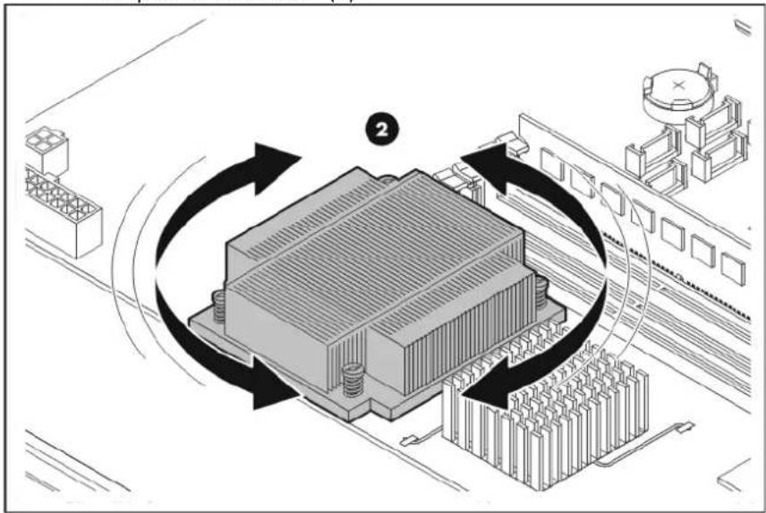
Technical diagram illustrating a mechanical or electrical component with labeled rotational directions and assembly steps.b. Rotate the heat sink a few degrees clockwise and counterclockwise to break the thermal compound bond loose (2).
text_image
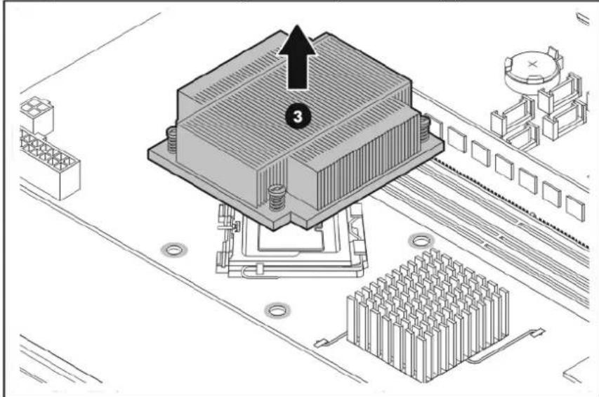
Technical diagram illustrating a mechanical or electronic component with labeled parts and directional arrows indicating motion or circulation.c. Lift the heat sink away from the system board (3).
text_image
Technical diagram of a computer motherboard with labeled components and a numbered arrow pointing to component 3- Lay the heat sink down in an upright position.
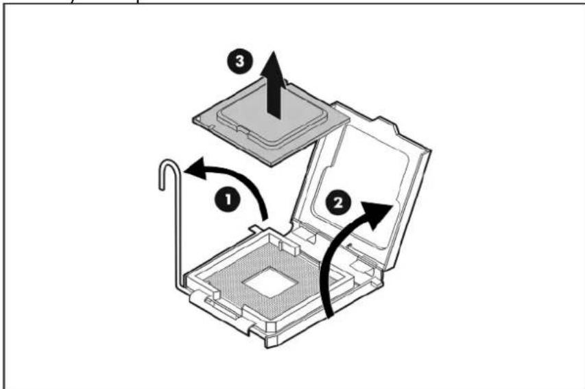
To remove the old processor:
- Rotate the load lever to the open position.
- Open the retention plate to expose the socket body.
- Gently lift the processor out of its socket.
text_image
Diagram of a computer processor internal structure with numbered components and directional arrows indicating assembly or movement.- Place the old processor on a static-dissipating work surface or inside an anti-static bag.
To apply thermal compound:
Perform the procedure below only if you will be using the same heat sink as before. If you are using a new one, there is no need to apply thermal compound as there is already a preapplied thermal compound in the new heat sink.

CAUTION: Applying too little thermal compound will cause a gap between the contact surfaces. This means that the heat sink is not even in direct contact with the processor, and therefore its capacity to draw out heat is greatly reduced. Furthermore, applying too much compound can make it squish out from the sides and go all over the processor pins or to the system board when the heat sink is installed. The compound may cause electrical shorts that can damage the system.
- Use the alcohol pad (included in the new processor spare kit) to clean the contact surfaces on the heat sink and the new processor. Wipe the contact surfaces several times to make sure that no particles or dust contaminants are evident. Allow the alcohol to evaporate before continuing.
△ CAUTION: Do not touch the contact surfaces as this may leave dead skin cells or oils from your finger that can result in poor thermal compound performance. - Apply 0.5 gram (0.25 ml) of the thermal compound evenly onto the top of the processor. The figure below shows the correct pattern of applying the thermal compound.
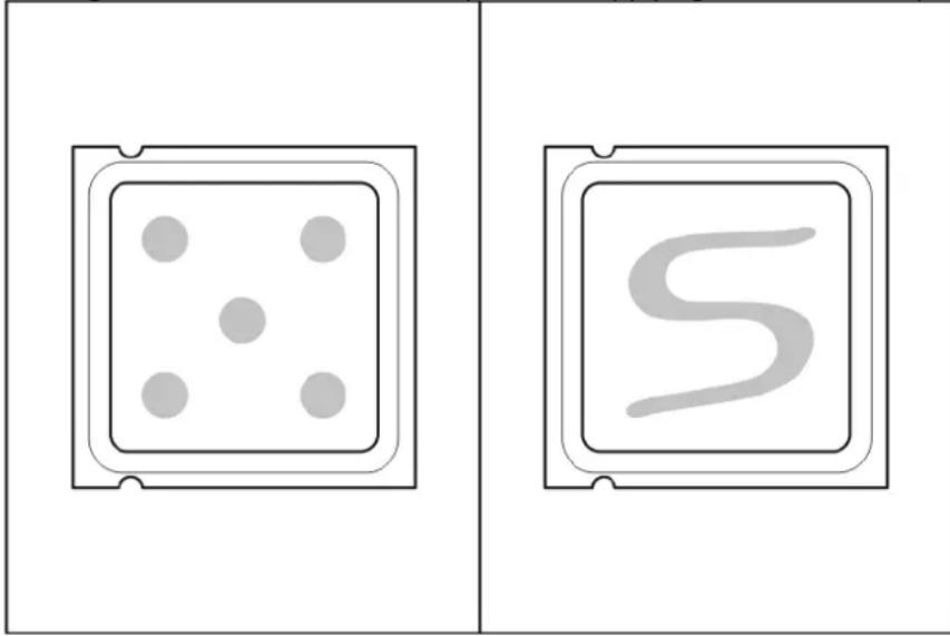
natural_image
Two identical rectangular panels: one with a dice and four dots, the other with a stylized 'S' inside (no text or symbols)To install the new processor:
- With the load lever and the retention plate still disengaged, align the processor with the socket and install the processor.
Make sure that the two notches and the orientation arrow on the processor are properly aligned with the tabs and beveled corner of the socket.
-
Close down the retention plate.
-
Rotate the load lever to the lock position.
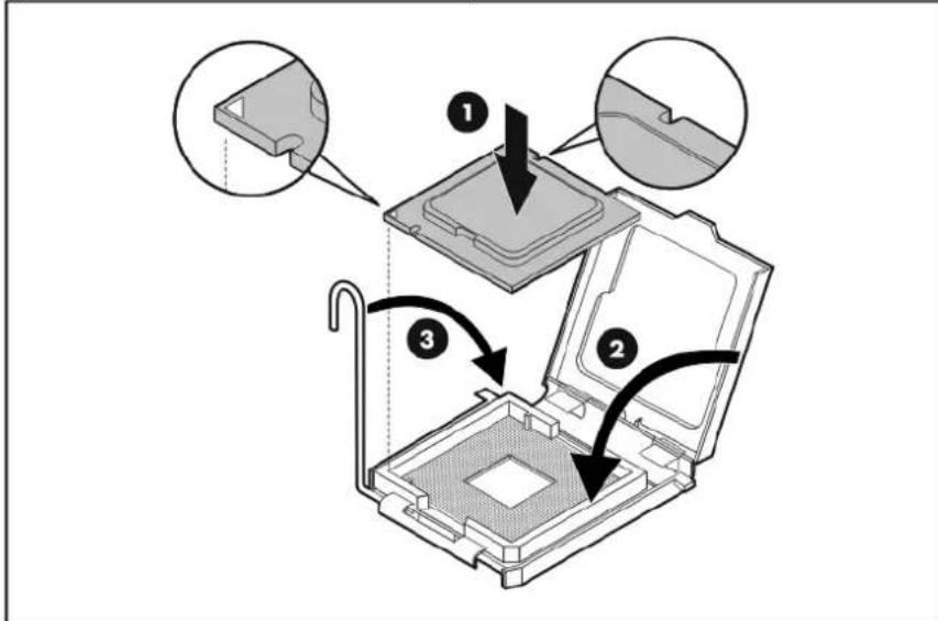
text_image
Diagram illustrating the step-by-step installation of a computer processor into a slot, with labeled parts and directional arrows.To install the heat sink:
CAUTION: To prevent overheating or a possible system crash, use only a heat sink specified for your ProLiant server.
-
If you are using a new heat sink, remove the cover protecting the preapplied thermal compound. Be careful not to touch or scratch the thermal compound.
-
Install the heat sink.
a. Insert the heat sink's spring-loaded screws into the system board holes (1).
b. Use the system screwdriver to tighten the spring-loaded screws (2).
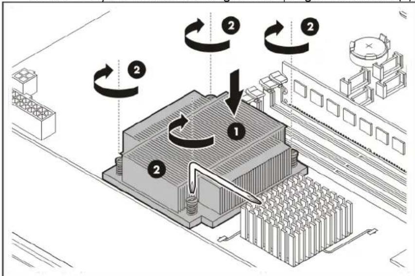
text_image
Technical diagram illustrating a mechanical or electrical component with labeled parts and rotational arrows indicating motion.-
Reinstall the air baffle.
-
Perform the post-installation procedure.
Memory
The system has four DIMM slots that support up to 8 GB maximum system memory (2 GB in each of the four DIMM slots).
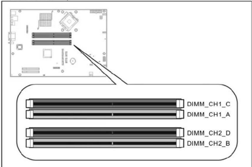
text_image
DIMM_CH1_C DIMM_CH1_A DIMM_CH2_D DIMM_CH2_BThe DIMM slots' holding clips are color-coded to indicate the correct population sequence in a single- or two-DIMM configuration.
- Black DIMM slots – DIMM CH1 C and DIMM CH2 D
• Blue DIMM slots – DIMM CH1 A and DIMM CH2 B
Memory installation guidelines
Observe the following important guidelines when installing memory modules:
- Use only HP supported 800 MHz unbuffered ECC DDR II DIMM in 512 MB, 1 GB, or 2 GB capacities.
- All DIMMs installed must be of the same speed.
• Supported DIMM configurations include:
o Single DIMM (non-interleaving) – It must be installed in the DIMM CH1 A slot.
- Two DIMMs (interleaving) – Populate the blue DIMM slots (DIMM_CH1_A and DIMM_CH2_B).
- Four DIMMs – For optimum performance, the amount of memory in the black DIMM slots should be equal to the amount in the blue DIMM slots.
- DIMMs can be damaged by improper handling. Always use an anti-static wrist strap and grounding mat, and discharge static electricity before touching DIMMs.
To install a memory module:
- Perform the pre-installation procedure.
- If necessary, remove any accessory boards or cables that prevent access to the DIMM slots.
- Locate an empty DIMM slot on the system board.
- If necessary, open the holding clips of the selected DIMM slot.
- Remove the memory module from its protective packaging, handling it by the edges.
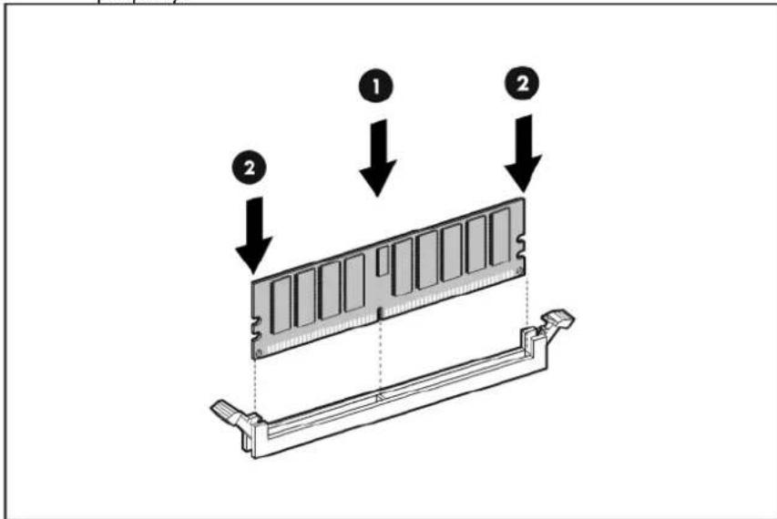
- Install the memory module.
a. Use both hands to hold the module by the edges, and then insert it perpendicularly into the slot (1). The DIMM slots are structured to ensure proper installation. If you insert a memory module but it does not fit easily into the slot, you may have inserted it incorrectly. Reverse the orientation of the module and insert it again.
b. Press the module at both ends to seat it fully into the slot (2).
The holding clips will automatically lock into place once the module has been seated properly.
text_image
Diagram showing a computer RAM module with two labeled arrows indicating assembly steps.- Perform the post-installation procedure.
Expansion board
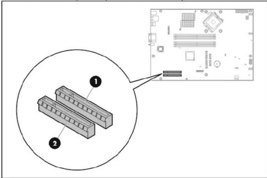
System board PCI expansion slots
There are two PCI Express expansion slots on the system board.
text_image
Diagram showing two labeled components (1 and 2) of a computer motherboard with an inset close-up of the circuit board.| Item | Slot code | Slot type | Interconnect | Function |
| 1 | Expansion_slot_2 | PCI Express x8 | x4 | Supports a low-profile riser board |
| 2 | Expansion_slot_1 | PCI Express x8 | x8 | Supports a full-length/full-height riser board |
| NOTE: The Expansion_slot_2 can support PCI Express x8 expansion boards but at x4 speed. | ||||
PCI riser board assembly
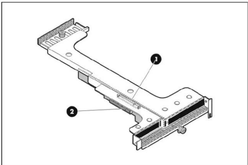
The two PCI Express riser boards attached to the PCI riser board assembly convert the functionality of the system board expansion slots to a pair of slots positioned at a 90° angle from the system board.
text_image
Technical diagram of a mechanical component with labeled parts 1 and 2Item Description
1 Full-length/full-height PCI Express x8 riser board
2 Low-profile PCI Express x8 riser board
NOTE: Users have the option to replace the full-length/full-height PCI Express x8 riser board with an optional 133 MHz/3.3V PCI-X model. This will allow support for PCI-X expansion boards. For more information, go to page 64.
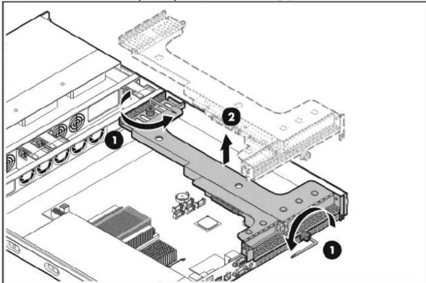
To remove the PCI riser board assembly:
- Perform the pre-installation procedure.
- Disconnect all cables connected to an existing expansion board.
- Remove the PCI riser board assembly.
a. Loosen the two captive thumbscrews that secure the assembly to the chassis (1).
b. Lift the assembly away from the chassis (2).
text_image
Technical diagram of a computer motherboard showing labeled components and directional arrows indicating movement or assembly.To reinstall the PCI riser board assembly:
- Align the assembly with the system board expansion slots, and then press it down to ensure full connection to the system board.
- Tighten the two captive thumbscrews to secure the assembly to the chassis.

text_image
Technical diagram showing a mechanical assembly with labeled components and directional arrows indicating motion or assembly.Installing an expansion board
Expansion board installation guidelines
The system supports up to two expansion boards at a time. Use only HP supported expansion boards that meet the following specifications:
- Compliance
o PCI Express x8
o PCI-X (available only when the optional PCI-X riser board is installed)
- Form factor
o Low-profile
o Full-height/full-length
To install an expansion board:
- Remove the PCI riser board assembly.
- Identify the riser board slot that is compatible with the expansion board you intend to install.
- Prepare the selected slot for expansion board installation.
a. Remove the screw that secures the slot cover (1).
Reuse this screw to install the expansion board.
b. Pull out the slot cover from the assembly (2).
Store it for reassembly later.

CAUTION: Do not discard the slot cover. If the expansion board is removed in the future, the slot cover must be reinstalled to maintain proper cooling.
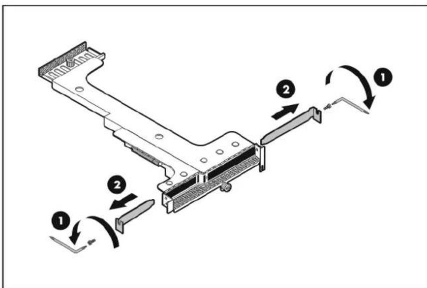
text_image
Technical diagram of a mechanical assembly with numbered components and directional arrows indicating motion or assembly steps.- Remove the expansion board from its protective packaging, handling it by the edges.
Some expansion boards can only be installed in one slot but other boards can be configured to fit in either slot by replacing the default bracket (attached to the board) with a different sized one. The different sized bracket and instructions on how to attach it to the board is included in the option kit.
- Verify that the board's default bracket is compatible with the configuration of the selected slot.
If it is not compatible, replace the bracket with one that is compatible.
- Install the expansion board.
a. Slide the expansion board into the slot (1).
Make sure the board is properly seated in the slot.
b. Secure the expansion board with the one screw (2).
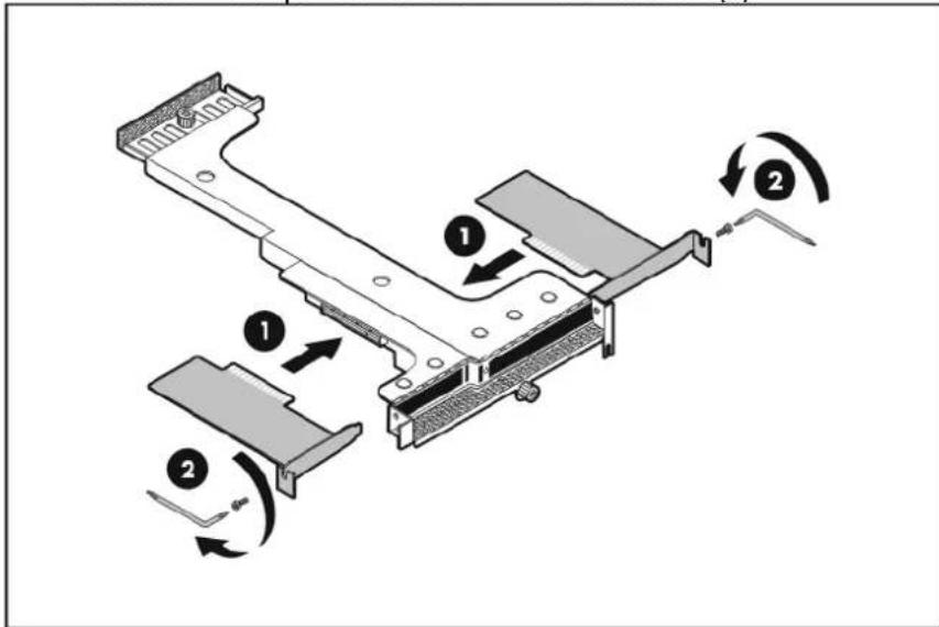
text_image
Technical diagram of a mechanical assembly with numbered components and directional arrows indicating motion or assembly.-
Reinstall the PCI riser board assembly to the chassis.
-
Connect the necessary cable(s) to the board.
Refer to the documentation that came with the board.
- Perform the post-installation procedure.
System battery
The server uses a nonvolatile memory that requires a battery to retain system information when power is removed. This 3-volt 230-mAh lithium coin cell battery is located on the system board.
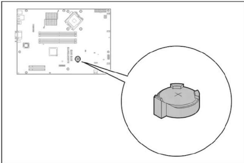
natural_image
Diagram showing a computer motherboard with an inset close-up of its internal components, no text or symbols present.If the server no longer automatically displays the correct date and time, the system battery that provides power to the real-time clock may need to be replaced. Under normal use, battery life is 5 to 10 years.
System battery replacement warnings
Observe the following reminders when replacing the system battery:
- Replace the battery with the same type as the battery recommended by HP. Use of another battery may present a risk of fire or explosion.
- A risk of fire and chemical burn exists if the battery is not handled properly. Do not disassemble, crush, puncture, or short external contacts, or expose the battery to temperatures higher than 60^ C ( 140^ F).
- Do not dispose of used battery in water or fire. Dispose of used batteries according to manufacturer's instructions.
- Loss of BIOS settings occurs when the battery is removed. BIOS settings must be reconfigured whenever the battery is replaced.
To replace the system battery:
- Perform the pre-installation procedure.
- If necessary, remove any accessory boards or cables that prevent access to the battery socket.
- Locate the system battery.
- Replace the system battery.
a. Squeeze the metal clamp that extends above one edge of the battery until the battery pops up (1).
b. Lift up the old battery to remove it (2).
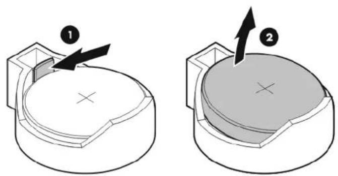
natural_image
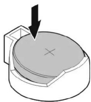
Two technical diagrams showing a mechanical component with arrows indicating motion or force, no text or symbols present.c. Slide one edge of the replacement battery under the holder's lip—positive side facing up—and then push the other edge down until the clamp snaps over the battery.
natural_image
3D diagram of a mechanical component with a downward arrow and cross symbol (no text or labels)- Perform the post-installation procedure.
Option kits
Refer to the following sections for instructions about how to install the SAS controller board, SAS HDD cable, SAS LED cable, PCI-X riser board, and Lights-Out 100c remote management card option kits.
SAS controller board and SAS HDD/LED cables
If you intend to change the system from a SATA to SAS configuration, first install the SAS controller board, and then connect the SAS HDD and LED cables.
NOTE: Remove the SATA HDD cables from the chassis if you intend to install a SAS hard disk drive.
To install the SAS controller board:
- Remove the PCI riser board assembly.
- Identify the riser board slot that is compatible with SAS controller board model you intend to install.
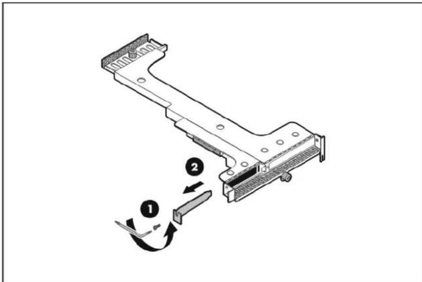
- Prepare the selected slot for controller board installation.
a. Remove the screw that secures the slot cover (1).
Reuse this screw to install the controller board.
b. Pull out the slot cover from the assembly (2).
Store it for reassembly later.
CAUTION: Do not discard the slot cover. If the controller board is removed in the future, the slot cover must be reinstalled to maintain proper cooling.
text_image
Technical diagram showing a mechanical assembly with labeled components and directional arrows indicating motion or assembly.-
Remove the controller board from its protective packaging, handling it by the edges.
-
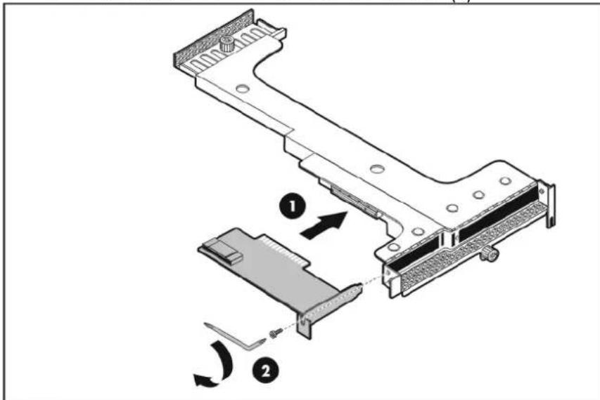
Install the controller board.
a. Slide the controller board into the slot (1). Make sure the board is properly seated in the slot.
b. Secure the controller board with the one screw (2).
text_image
Technical diagram of a mechanical assembly with numbered components and directional arrows indicating motion or assembly steps.-
Reinstall the PCI riser board assembly to the chassis.
-
Proceed to the next section for instructions on how to connect the SAS HDD and LED cables.
To connect the SAS HDD and LED cables:
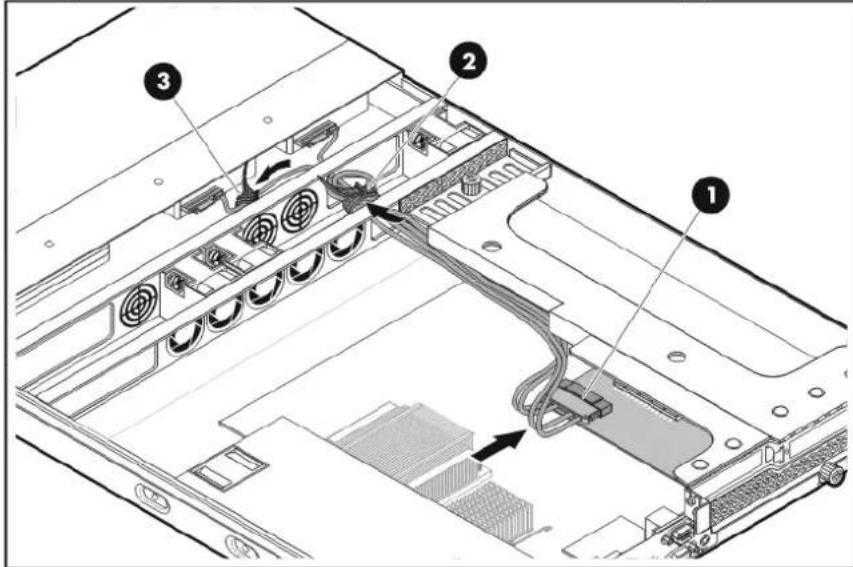
- Connect the SAS HDD cable.
a. Connect the cable's master connector to the SAS controller board (1).
b. Route the SAS cable lines underneath the PCI riser board assembly and through the drive cable opening of the center wall, and then secure the SAS cable lines in the chassis cable tie (2).
c. Secure the SAS cable lines in the chassis cable tie (3).
text_image
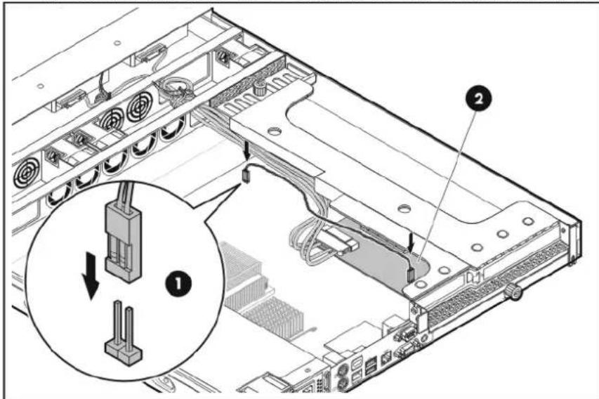
Technical diagram of an internal server rack with labeled components including ports, connectors, and a cable.- Connect the SAS LED cable.
a. Connect the other end of the LED cable to the CN26 connector on the system board (1).
b. Connect one end of the LED cable to the SAS controller board LED cable connector (2).
text_image
Technical diagram of an internal server rack with labeled components and a magnified view showing component 1.- Proceed to page 37 for instructions on how to install the SAS hard drive.
PCI-X riser board
You can replace the full-length/full-height PCI Express x8 riser board with an optional 133 MHz/3.3V PCI-X model. This will allow installation of PCI-X compatible expansion boards.
NOTE: For ease of reading, the PCI riser board assembly will simply be referred to as "assembly" in this section.
To install the PCI-X riser board:
- Remove the PCI riser board assembly.
- If an expansion board is currently installed on the full-length/full-height PCI Express x8 riser board, remove it.
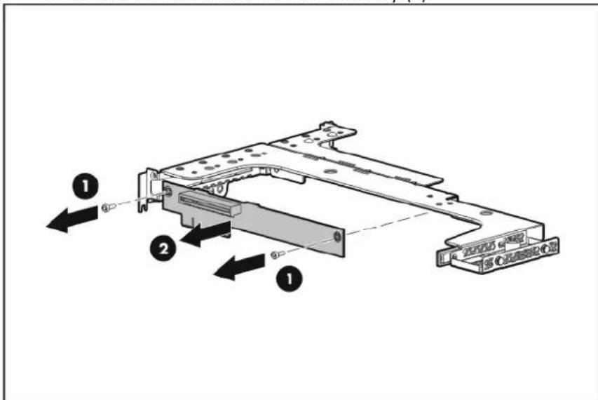
- Remove the full-length/full-height PCI Express x8 riser board.
a. Remove the two screws that secure the riser board (1).
Reuse these screws when you install the PCI-X riser board.
b. Detach the riser board from the assembly (2).
text_image
Technical diagram of a mechanical assembly with numbered components and directional arrows indicating assembly steps.-
Remove the PCI-X riser board from its protective packaging.
-
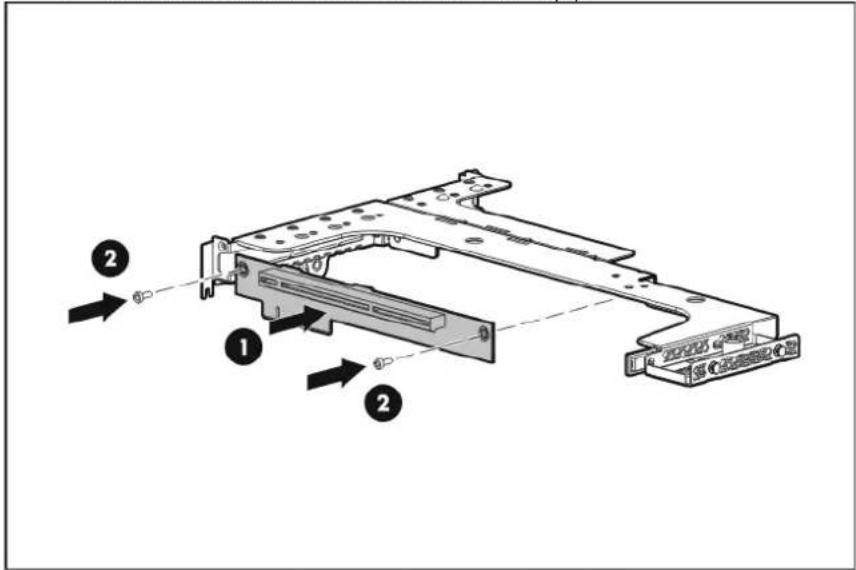
Install the PCI-X riser board.
a. Align the riser board on the assembly (1).
b. Secure the riser board with two screws (2).
text_image
Technical diagram of a computer chassis with labeled components and directional arrows indicating assembly or movement.- Reinstall the PCI riser board assembly.
- Perform the post-installation procedure.
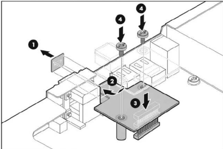
Lights-Out 100c remote management card
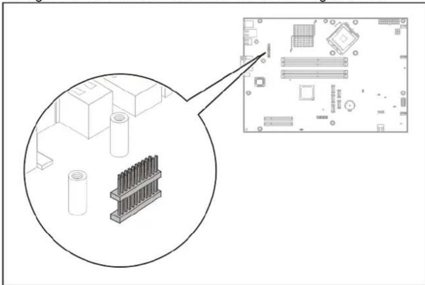
The HP Lights Out 100c remote management card (IPMI 2.0 compliant) allows users to perform server management tasks remotely over a LAN or the Internet. It also has a health monitoring function that tracks and records system events related to the fan status, system temperature, and voltage condition. The Lights-Out 100c module connector is shown in the figure below.
natural_image
Technical illustration of a computer motherboard with an inset close-up showing internal components (no text or symbols)To install the Lights Out 100c remote management card:
-
Perform the pre-installation procedure.
-
Locate the Lights-Out 100c module connector on the system board.
-
Remove the Lights-Out 100c blank bracket.
a. Remove the remote management port cover (1).
b. Position the module between the USB and video ports (2).
c. Attach the module to the CN6 connector (3).
d. Secure the module with the two screws that came with the module option kit (4).
text_image
Technical diagram showing a mechanical assembly with numbered components and directional arrows indicating assembly steps.- Perform the post-installation procedure.
System fans
The server has three system fans located on the chassis' center wall. The figure below identifies the system fans by their device number and shows their corresponding cable connections.
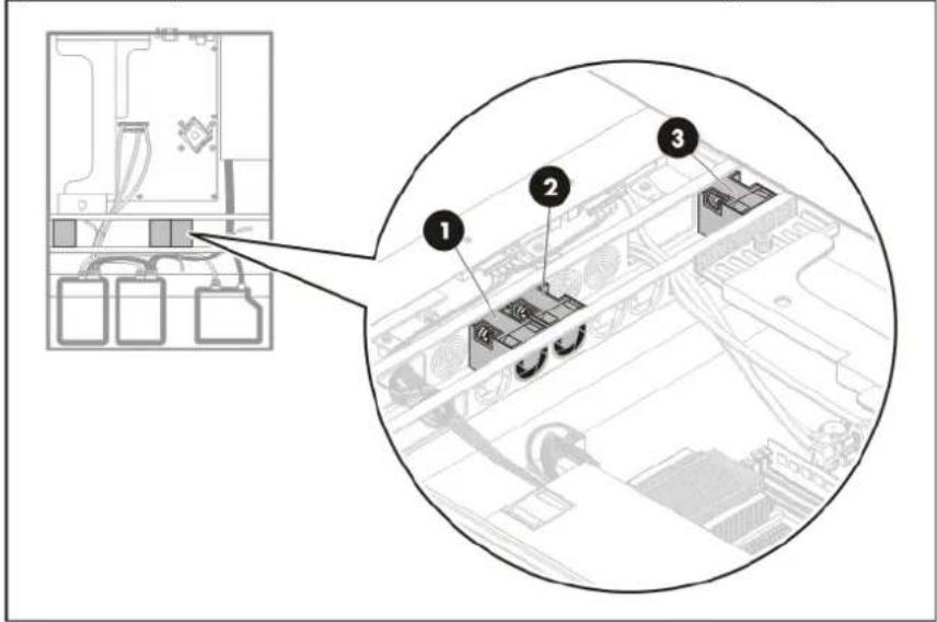
text_image
Technical diagram showing a device layout with labeled components, including a zoomed-in view of the interior panel.| Device number | System board connector |
| 1 | CPU_FAN1 |
| 2 | CPU_FAN2 |
| 3 | SYSFAN |
NOTE: Fan 1 and 2 are for the processor and DIMMs; fan 3 is for the expansion boards.
A new system fan can be installed to allow the server to operate properly in case the default system fan becomes defective.
NOTES:
- If you are replacing the system fans 1 or 2, remove the air baffle first to be able to unlatch the fan cable from the chassis. Reinstall the air baffle after installing the new system fan.
- If you are replacing the system fan 3, remove the PCI riser board assembly first to be able to unlatch the fan cable from the chassis. Reinstall the PCI riser board assembly after installing the new system fan.
To replace a system fan:
-
Perform the pre-installation procedure.
-
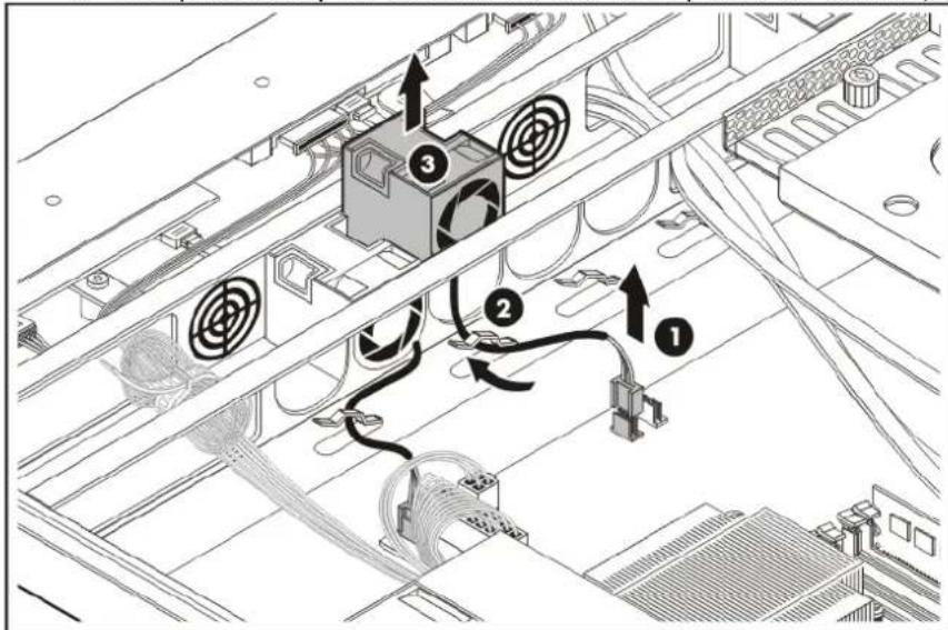
Remove the defective system fan:
a. Disconnect the fan cable from its system board connector (1).
b. Unlatch the fan cable from the chassis cable clip (2).
c. Grasp the fan by the blue handle, and lift it up from the chassis (3).
text_image
Technical diagram of a server rack with labeled components and wiring connections-
Remove the system fan from its protective packaging.
-
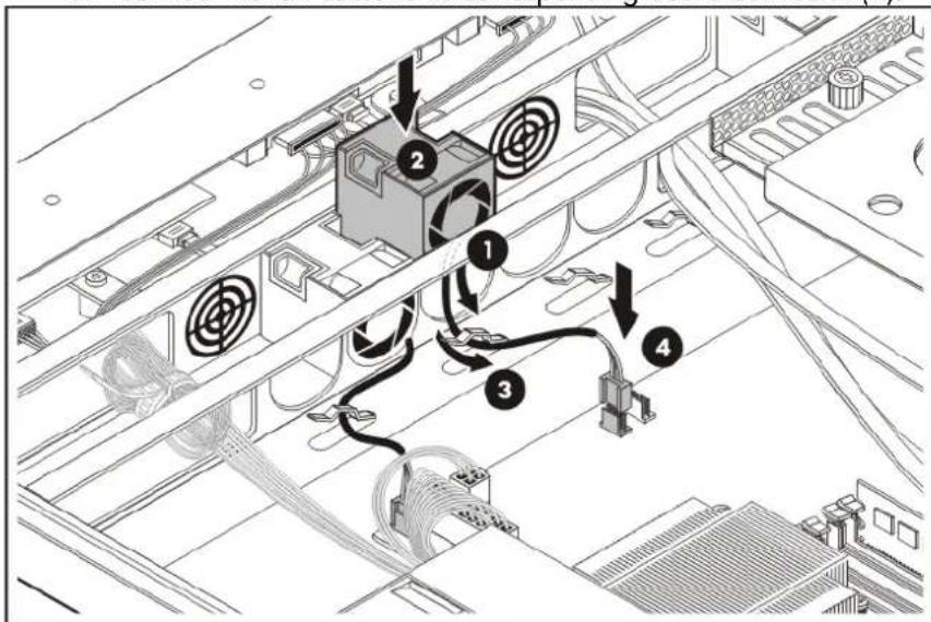
Install the new system fan.
a. Route the fan cable through the vacated fan bracket (1).
d. Connect the fan cable to its corresponding board connector (4).
text_image
Technical diagram of an electronic device with labeled components and wiring connections- Perform the post-installation procedure.
Power supply unit
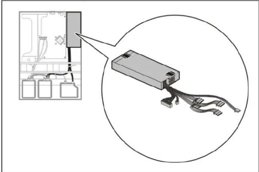
Located on the right rear side of the server is a single standard autoranging 350-watts PSU with PFC (power factor correction) function.
natural_image
Diagram showing a battery pack connected to an electronic device via cable, with no visible text or symbols.PSU replacement warnings
Observe the following reminders to reduce the risk of personal injury from electric shock hazards and/or damage to the equipment
- Installation of the power supply unit should be referred to individuals who are qualified to service server systems and are trained to deal with equipment capable of generating hazardous energy levels.
• DO NOT open the power supply unit. There are no serviceable parts inside it.
To replace the power supply unit:
-
Perform the pre-installation procedure.
-
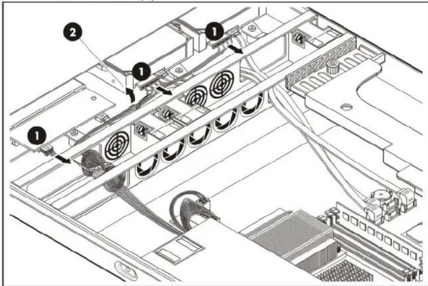
Disconnect the system power cables.
a. Disconnect all power cables connected to the system drives (1).
b. Unlatch the drive power cables from the front chassis cable tie, and then pull them through the center wall (2).
text_image
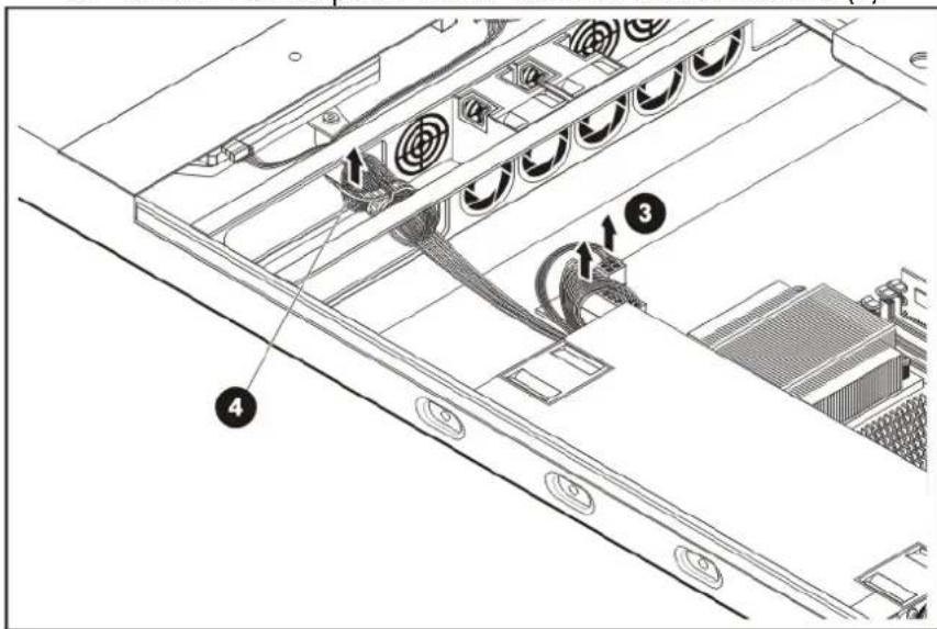
Technical diagram of a server rack with labeled components and cable routing arrowsc. Disconnect the system board's (PWR_CN) and processor's (CN4) ATX power cables from their system board connectors (3).
d. Unlatch the ATX power cables from their chassis cable tie (4).
text_image
Technical diagram of a server rack with labeled components and cable routing arrows- Remove the default power supply unit.
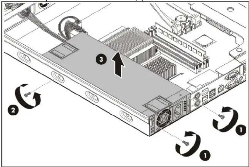
Reuse the three screws you removed in this step for installing the new PSU.
a. Remove the two PSU screws on the rear panel (1).
b. Remove the single PSU screw on the side of the chassis (2).
c. Lift up the PSU from the chassis (3).
text_image
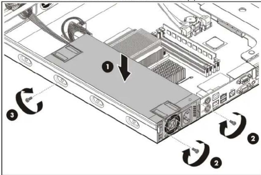
Diagram of an internal server rack with numbered components and directional arrows indicating rotation or data flow.- Install the new power supply unit.
a. Lay down the new unit in the PSU section of the chassis (1).
b. Insert the two PSU rear panel screws (2).
c. Insert the one PSU screw on the side chassis (3).
text_image
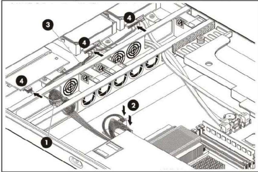
Diagram of a computer drive showing labeled components and clockwise rotation arrows indicating mechanical or electrical movement.- Connect the PSU cables.

IMPORTANT: Check the PSU cable label before connecting them. Go to page 36 for a reference figure on proper PSU cable connections.
a. Secure the ATX power cables to the chassis cable tie (1).
b. Connect the ATX power cables to their system board connectors (2).
c. Route the system drive power cables through the center wall, and then secure them to the chassis cable tie (3).
d. Connect the power cables of all installed system drives (4).
text_image
Technical diagram of a server rack with numbered components and cable routing arrows indicating assembly steps.- Perform the post-installation procedure.
Diagnostic tools
HP Insight Diagnostics
HP Insight Diagnostics is a proactive server management tool, available in both offline and online versions, that provides diagnostics and troubleshooting capabilities to assist IT administrators who verify server installations, troubleshoot problems, and perform repair validation.
HP Insight Diagnostics Offline Edition performs various in-depth system and component testing while the OS is not running. To run this utility, launch the Support CD.
HP Insight Diagnostics Online Edition is a web-based application that captures system configuration and other related data needed for effective server management. Available in Microsoft® Windows® and Linux versions, the utility helps to ensure proper system operation.
For more information or to download the utility, refer to the HP website (http://www.hp.com/servers/diags).
Array Diagnostic Utility
The HP Array Diagnostics Utility is a web-based application that creates a report of all HP storage controllers and disk drives. This report provides vital information to assist in identifying faults or conditions that may require attention. ADU can be downloaded from the HP website (http://www.hp.com).
IPMI Event Log
The IPMI Event Log is a log that is generated by the management controller when it detects significant or critical system management events. This includes messages for events such as 'temperature threshold exceeded', 'voltage threshold exceeded', 'power fault', etc.
To view the IPMI event log:
- Turn on the monitor and the server.
If the server is already turned on, save your data and exit all open applications, and then restart the server.
- During POST, press F10 to access the Phoenix BIOS Setup Utility.
- In the Advanced menu screen, select the IPMI field, and then press Enter.
- Select System Event Log, and then press Enter.
Phoenix BIOS software
Your ProLiant server uses BIOS to boot up the system. Phoenix BIOS software is a ROM BIOS-based firmware that allows reliability, manageability, and connectivity for server platforms. This software contains a set of programs permanently stored in an EEPROM chipset located on the system board. These programs assist in managing, initializing, and testing the hardware devices installed on the computer.
The Phoenix BIOS software serves three functions:
- Configure the system from the Phoenix BIOS Setup Utility Using the Setup program, you can install, configure, and optimize the hardware devices on your system (clock, memory, disk drives, etc.). In addition, you can enable various features such as serial console redirection, PXE boot, and much more.
- Initialize hardware at boot using POST routines During power-on or warm reset, the software performs Power-On Self-Test (POST) routines to test components, to allocate resource for various hardware devices, and to prepare the system to boot to various operating systems.
- Perform run-time routines Using the software, perform basic hardware routines that can be called from DOS and Windows applications.
Configuring the system BIOS
NOTE: For ease of reading, Phoenix BIOS Setup Utility will be simply referred to as "Setup" or "Setup Utility" in this guide. Also, the screenshots used in this guide display various Setup menu screens with the default values identified. These values may not be the same as those in your server.
Phoenix BIOS Setup Utility is a hardware configuration program built into your system's Basic Input/Output System (BIOS). Since most systems are already properly configured and optimized, there is normally no need to run this utility.
You will need to run this utility under the following conditions:
- When changing the system configuration including:
- Setting the system time and date
○ Configuring the hard drives
o Specifying the boot device sequence
○ Installing PCI expansion boards - Upgrading the system BIOS
○ Configuring the power management modes - Setting up system passwords or making other changes to the security setup
- When a configuration error is detected by the system and you are prompted (Run Setup message) to make changes to the BIOS settings.
NOTE: If you repeatedly receive Run Setup messages, the system battery may be defective. In this case, the system cannot retain configuration values in CMOS. Replace the system battery with a new one.
The Setup Utility loads the configuration values in a battery-backed nonvolatile memory called CMOS RAM. This memory area is not part of the system RAM, which allows configuration data to be retained when power is turned off. The values take effect when the system is booted. POST uses these values to configure the hardware. If the values and the actual hardware do not agree, POST generates an error message. You must run this utility to change the BIOS settings from the default or current configuration.
The Setup Utility has five primary menu selections, including:
- Main
- Boot
- Advanced
- Exit
- Security
To run the Setup Utility:
- Turn on the monitor and the server.
If the server is already turned on, save your data and exit all open applications, and then restart the server.
- During POST, press F10.
If you fail to press F10 before POST is completed, you will need to restart the server.
The first page to be displayed will be the Main menu showing the Setup Utility's menu bar. Use the left ( ) and right ( ) arrow keys to move between selections on the menu bar.
Setup Utility navigation keys
Use the following keyboard keys to work your way through the various menu and submenu screens of the Setup Utility.
| Key | Functions |
| ← and → To move between selections on the menu bar. | |
| ↑ and ↓ To move the cursor to the field you want.The currently selected field will be highlighted. The right side of each menu screen displays theItem Specific Helppanel. This panel displays the help text for the currently selected field. It updates as you move the cursor to each field. | |
| PgUp and PgDn To move the cursor to the previous and next page of a multiple page menu. | |
| Home To move the cursor to the first page of a multiple page menu. | |
| End To move the cursor to the last page of a multiple page menu. | |
| (+), (-), and | To select a value for the currently selected field (only if it is user-configurable).Press the (+), (-), orkeys repeatedly to display each possible entry, or theEnterkey to choose from a pop-up menu.A parameter that is enclosed in square brackets [ ] is user-configurable.Grayed-out parameters are not user-configurable for one of the following reasons:The field value is auto-configured or auto-detected.The field value is informational only.The field is password-protected. |
| Enter | To select a field value or display more options for menu marked with ▶. |
| Ctrl+Enter To expand all device lists. | |
| F1 or | To bring up theGeneral Helpwindow.TheGeneral Helpwindow describes other Setup navigation keys that are not displayed on the legend bar. |
| Esc or | If you press this key:On one of the primary menu screens, theExitmenu displays.On a submenu screen, the previous screen displays.When you are making selections from a pop-up menu, closes the pop-up without making a selection. |
| F9 Loads the default system values. | |
| F10 Saves changes and closes the Setup Utility. | |
Setup Utility menus
The Setup Utility provides a menu bar with the menu selections. The menu bar choices are described in the following sections.
Main menu
| PhoenixBIOS Setup Utility | |||||
| Main | Advanced | Security | Boot | Exit | |
| Item Specific Help | |||||
| ProLiant BIOS: 022 BIOS Version V0.13 Build Date 02/19/08 | |||||
| CPU Type Intel® Xeon® CPU CPU Speed 2.66 GHz Physical CPUs 1 of 1 Enable Installed Memory 6144MB | , , or selects field | ||||
| Embedded NIC1 MAC Address : 00.1F.29.0E.07.F3 Set Server Asset Text : [0123456789abcde] Set Serial Number Text : 0123456789ABCDEF ► Boot Features | |||||
| System Time [11:34:20] System Date: [02/22/2008] | |||||
| F1 Help ↑↓ Select Item -/+ Change Values F9 Setup Defaults ESC Exit — Select Menu Enter Select ► Sub-Menu F10 Save and Exit | |||||
| Field | Description |
| ProLiant BIOS System BIOS name | |
| BIOS Version System BIOS version | |
| Build Date Date when the Setup BIOS was created | |
| CPU Type Processor model name | |
| CPU Speed Processor speed | |
| Physical CPUs Number of installed processors | |
| Installed Memory System memory size detected during POST | |
| Embedded NIC1 MAC Address MAC address of the embedded NIC | |
| Set Server Asset Text | Enter the server asset tag and serial number. These information are printed on the serial label tab located on the front panel. |
| Set Serial Number Text | |
| Boot Features Set which options to run during system bootup.Press Enter to access the related submenu. | |
| System Time Adjust the system time. | |
| System Date Adjust the system date. | |
Advanced menu
| PhoenixBIOS Setup Utility | ||||
| Main | Advanced | Security | Boot | Exit |
| Item Specific Help | ||||
| ► Advanced Chipset Control ► Advanced Processor Options ► I/O Device Configuration ► Hard Disk Configuration ► USB Configuration ► Console Redirection ► IPMI Reset Configuration Date : [No] ► WHEA - Test | <Tab>, <Shift-Tab>, or <Enter> selects field | |||
| Field | Description |
| Advanced Chipset Control Displays the settings related to the system chipsets. Press Enter to access the related submenu. | |
| Advanced Processor Options Displays the settings related to the processor. Press Enter to access the related submenu. | |
| I/O Device Configuration Displays the settings related to the serial port. Press Enter to access the related submenu. | |
| Hard Disk Configuration Displays the settings related to the system hard drives. Press Enter to access the related submenu. | |
| USB Configuration Displays the settings related to the USB function. Press Enter to access the related submenu. | |
| Console Redirection Displays console redirection-related settings. Press Enter to access the related submenu. | |
| IPMI Displays server management-related settings. Press Enter to access the related submenu. | |
| Reset Configuration Data | Select whether to erase data in the section of memory for ESCD (Extended System Configuration Data) which stores the configuration settings for non-PnP plug-in devices. |
Security menu
| PhoenixBIOS Setup Utility | ||||
| Main Advanced Security Boot Exit | ||||
| Supervisor Password Is : Clear Set Supervisor Password [Enter] Password on Boot: [Disabled] | Item Specific Help | |||
| , or selects field | ||||
| F1 Help ↑↓ Select Item -/+ Change Values F9 Setup Defaults ESC Exit → Select Menu Enter Select ▶ Sub-Menu F10 Save and Exit | ||||
| Field | Description |
| Supervisor Password Is Current supervisor password status (Clear or Enabled) | |
| Set Supervisor Password | Select the field, and then press Enter to set, change, or remove a supervisor password. |
| Password on Boot Select whether to require the supervisor password during bootup. | |
Supervisor password
The Security menu allows users to set a supervisor password. When entered, this password will allow the user to access and change all settings in the Setup Utility.
To set a supervisor password:
- In the Security menu screen, select the Supervisor Password Is field then press Enter.
- Type a new password in the password box.
The password may consist of up to eight alphanumeric characters (A-Z, a-z, 0-9). - Retype the password to verify the first entry, and then press Enter.
- Press F10 to save the password and close the Setup Utility.
After setting the password, the Supervisor Password Is field value is set to Enabled.
To change the supervisor password:
- In the Security menu screen, select the Supervisor Password Is field, and then press Enter.
- Type the original password in the password box.
- Type a new password, and then press Enter.
- Retype the new password to verify the first entry, and then press Enter again.
- Press F10 to save the password and close the Setup Utility.
To remove the supervisor password:
- In the Security menu screen, select the Supervisor Password Is field, and then press Enter.
- Type the original password then press Enter.
- Press Enter twice without entering anything in the new and confirm password fields.
- Press F10 to save the changes you made and close the Setup Utility.
The Supervisor Password Is field value is set to Clear.
To reset the supervisor password:
If you forget the supervisor password, you need to clear the CMOS and reset the BIOS settings to regain access the Setup Utility. For instructions, refer to the "Clearing CMOS" section on page 84.
Boot menu
Use this menu to set the preferred drive sequence in which the Setup Utility attempts to boot the operating system.
By default, the server searches for boot devices in the following order:
• CD-ROM/DVD-ROM drive
- Removable device
- Hard drive
- Embedded NIC (via Preboot Execution Environment—remote boot over LAN)
To implement the PXE boot option, you need to first set the Embedded NIC1 PXE field to Enabled.
| PhoenixBIOS Setup Utility | |
| Main Advanced Security Boot Exit | |
| CD-ROM/DVD-ROM Removable Devices +Hard Drive Embedded NIC Embedded NIC1 PXE ; [Enabled] | Item Specific Help |
| , , or selects field | |
| F1 Help ↑↓ Select Item -/+ Change Values F9 Setup Defaults ESC Exit —— Select Menu Enter Select ▶ Sub-Menu F10 Save and Exit | |
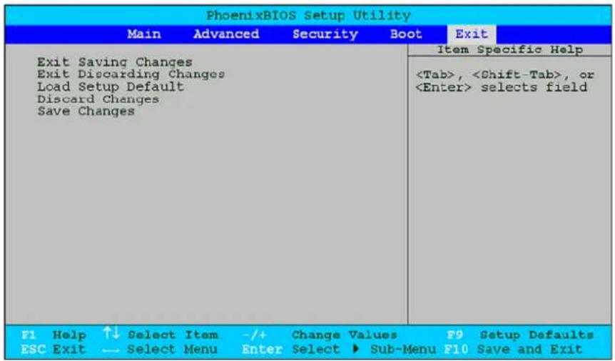
Exit menu
text_image
PhoenixBIOS Setup Utility Main Advanced Security Boot Exit Exit Saving Changes Exit Discarding Changes Load Setup Default Discard Changes Save Changes Item Specific Help| Field | Description |
| Exit Saving Changes | Saves changes made and closes the Setup Utility. |
| Keyboard shortcut: F10 | |
| Exit Discarding Changes | Discards changes made and closes the Setup Utility. |
| Load Setup Default | Loads the factory-default settings for all Setup fields. |
| Keyboard shortcut: F9 | |
| Discard Changes | Discards all changes made to the Setup Utility and loads the previous configuration settings. |
| Save Changes | Saves all changes made to the Setup Utility. |
Boot-time diagnostic screen
The boot-time diagnostic screen displays basic and important information about the current server configuration and is necessary for troubleshooting and may be required when asking for technical support. It is recommended that you check this screen during the initial system setup and each time you install, remove, or upgrade accessories.
To view the boot-time diagnostic screen:
You first need to enable the display of the diagnostic screen during bootup. Follow the steps below.
- In the Main menu screen, select Boot Features, and then press Enter.
- Select the Boot-time Diagnostic Screen field.
- Press the plus (+) or minus (−) key to set the field to Enabled.
- Press F10 to save the changes you made and close the Setup Utility.
5. Reboot the server.
The diagnostic screen is displayed briefly at the end of POST.

text_image
Phoenix cME FirstBIOS Pro Setup Utility CPU Type : Intel ® Xeon ® CPU X3350@ 2.66 Ghz CPU Speed : 2.66 GHz Logical CPUs : 4 of 4 Enabled Physical CPUs : 1 of 1 Enabled System ROM : E690 - FFFF Installed Memory : 6144 MB Build Date : 02/19/2008 Hard Disk 1 : None Hard Disk 4 : None Hard Disk 2 : None Hard Disk 5 : None Hard Disk 3 : None Hard Disk 6 : None-
Press the Pause/Break key to continue displaying the screen until another key is pressed.
-
Press any key to continue with the system bootup.
Updating/recovering the system BIOS
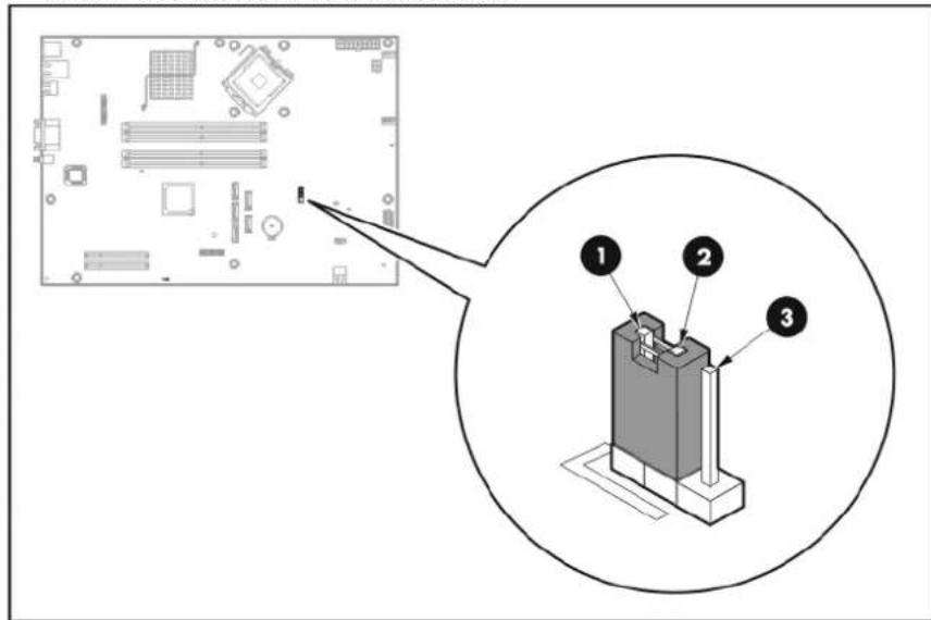
An interruption during the BIOS upgrade/recovery process (e.g. a power outage) can corrupt the BIOS code, which will cause the system to go into an unbootable state. Enabling the boot block program lets users restart the system and recover the regular BIOS code.
Use the JP5 jumper to enable the boot block.
• 1 - 2: Normal operation (default)
• 2 - 3: Configure BIOS
- Removed: Access the boot block code
text_image
Diagram showing a computer motherboard with labeled components and an inset view of the internal structure.
IMPORTANT: A power interruption during the BIOS update/recovery process can corrupt the system BIOS code. Make sure the server is connected to a UPS unit during the update process.
To perform a BIOS update/recovery:
-
Go to http://www.hp.com/go/support and download the System ROMPaq Firmware Upgrade Utility for your ProLiant server.
-
Use the ROMPaq Diskette Creator to create a bootable ROMPaq diskette which should contain the following files:
o CONFIG.sys
- CPQO2202.xxx
- CPQSRVR2.cpu
- ROMPAQ.exe
- Insert the bootable ROMPaq diskette you created in a USB floppy drive.
- Perform the pre-installation procedure.
- Remove the PCI riser board assembly.
- Locate the boot block jumper on the system board.
- Remove the jumper block.
- Connect the USB floppy drive with the bootable ROMPaq diskette to your ProLiant server.
- Perform the post-installation procedure.
Once you power on the server, it will boot from the USB floppy drive and automatically execute BIOS update/recovery. The process will take approximately 20 to 30 minutes. When the USB floppy drive activity LED stops blinking, the process is complete.
- Disconnect the USB floppy drive from the server.
- Repeat steps 4 through 6.
- Return the jumper block to its default 1-2 position.
- Perform the post-installation procedure.
Recording custom Setup values
Keep a record of the custom Setup values you have set up for your system BIOS. If the custom values ever need restoring (after a CMOS clear, for example), you must run the Setup Utility and enter these custom settings again. Make sure to update this record whenever you make any change to these Setup settings or install new hardware.
To manually record the custom Setup values:
- Access the Setup utility.
- Go through each menu and submenus page, and press Print Screen to make a hard copy.
- For multiple page menus, move to each page and print each screen.
If a printer is not available, write down the values on a piece of paper. Make sure to write them down legibly and accurately. - Label and date the Setup values hard copy, and then store it in a safe and accessible place, preferably with other user documentation for your ProLiant server.
Loading system defaults
If your system fails after you make changes in the Setup menus, reboot the server, enter Setup and load the system default settings to correct the error. These default settings have been selected to optimize your server's performance.
To load the system defaults:
- Reboot the server in a normal manner.
- During POST, press F10 to access the Setup Utility.
- Press F9 to load the default values.
- Press F10 to save the changes you made and close the Setup Utility.
Clearing CMOS
You may need to clear the Setup configuration values (CMOS) if the configuration has been corrupted, or if incorrect settings made in the Setup Utility caused error messages to be unreadable. Clearing the CMOS data removes the supervisor password.
Use the JP7 jumper to clear the CMOS data.
• 1 - 2 position: Normal operation (default)
• 2 - 3 position: Clear CMOS data
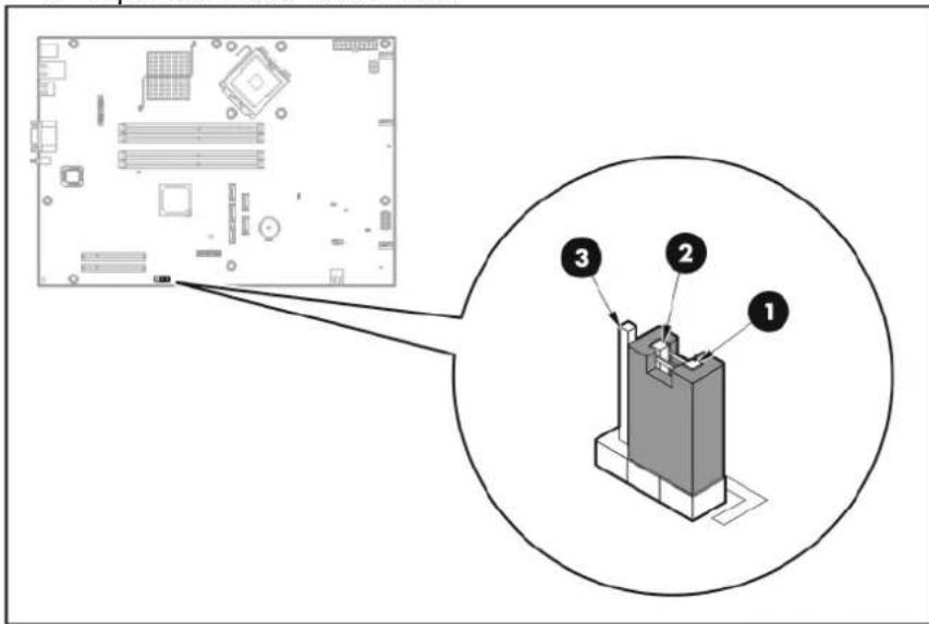
text_image
Diagram showing a computer motherboard with labeled components and an inset view of the internal structure.To clear CMOS:
- Perform the pre-installation procedure.
- Remove the PCI riser board assembly.
- Locate the clear CMOS jumper on the system board.
- Remove the jumper block and set it over the 2-3 pins for 20 to 30 seconds.
- Return the jumper block to its default 1-2 position.
- Perform the post-installation procedure.
- During POST, press F10 to access the Setup Utility.
- Press F9 to load the system default values.
- Press F10 to save the changes you made and close the Setup Utility.
Power-On-Self-Test
Before you can use a server, all devices must be tested and initialized, and the operating system must be bootstrapped to the memory. This is referred to as Power-On-Self-Test or POST. POST is a series of diagnostic tests that checks firmware and hardware components to ensure that the server is properly functioning. This diagnostic function automatically runs each time the server is powered on.
These diagnostics, which reside in the BIOS ROM, isolate server-related logic failures and indicate the board or component that needs to be replaced, as indicated by the error messages. Most server hardware failures will be accurately isolated during POST. The number of tests displayed depends on the configuration of the server.
During POST you can press:
- Esc to skip the HP logo and go to POST boot progress display system summary screen.
• F10 to access the Setup Utility.
• F12 to request a network boot (PXE).
POST error messages
Whenever a non-critical error occurs during POST, an error message describing the problem appears onscreen. These text messages are displayed in normal video (white text on black background). It shows the details of the error. The following is an example of a POST error message:
ERROR
0251: System CMOS checksum bad - Default configuration used
In some cases an error message may include recommendations for troubleshooting or require that you press the Enter key to display recommendations. Follow the instructions on the screen.
The next table lists the most common POST error messages with their corresponding troubleshooting recommendation. It is recommended that you correct the error before proceeding, even if the server appears to boot successfully.
If your system displays one of the messages marked below with an asterisk (*), write down the code and message and contact your HP Customer Support provider.
| Error code | Error message | Corrective action/description |
| 0200 | Failure Fixed Disk | Fixed disk is not working or was not configured properly.1 Run Setup and check if the fixed-disk type is correctly identified.2 Check to see if the fixed disk is attached properly. |
| 0210 | Stuck key | Stuck key on keyboard.1 Locate the stuck key on your keyboard and release it.2 Reboot the server. |
| 0211 | Keyboard error | Keyboard not working.Verify that the keyboard cable is securely connected to the keyboard port (not the mouse port) on the rear panel of the server.If the problem persists, replace the keyboard or contact your HP Customer Support provider. |
| 0212 | Keyboard Controller | Failed Keyboard controller failed test. |
| 0213 | Keyboard locked | - Unlock key switch Keyboard error. Replace the keyboard. |
| 0220 | Monitor type does not match CMOS - Run SETUP | The attached monitor cannot be correctly identified by Setup.Run Setup and check if the monitor type is correctly identified. |
| 0230 | Shadow RAM Failed at offset: nnnn | One or more defective memory module.1 Remove all installed DIMMs.2 Reinstall the DIMMs one by one to identify the defective module.3 Replace the defective DIMM with a new one. |
| 0231 | System RAM Failed at offset: nnnn | |
| 0232 | Extended RAM Failed at offset: nnnn | |
| 0250 | System battery is dead - Replace and run SETUP | The CMOS clock battery indicator shows the system battery is dead.1 Replace the system battery following the procedures on page 59.2 Run Setup to reconfigure the system. |
| 0251 | System CMOS checksum bad - Default configuration used | The settings in the Setup Utility have been corrupted or modified incorrectly, perhaps by an application program that changes data stored in CMOS.Access Setup, and then either load the system default values or enter your own custom values.If the error persists, check the system battery or contact your HP Customer Support provider. |
| 0260 | System timer error | The timer test failed. Requires repair of the system board. |
| 0270 | Real time clock error | Real-Time Clock (RTC) fails BIOS hardware test.May require board repair. |
Error code Error message Corrective action/description
| 0271 | Check date and time settings BIOS found date or time is out of range. May require setting legal date (1991-2099). Access Setup and check the values in the System Time and System Date fields of the Main menu. | |
| 0280 | Previous boot incomplete - Default configuration used | Initial bootup failed. BIOS automatically loads the default system values and then boots again. |
| 0281 | Memory size found by POST differed from EISA CMOS | The user added or removed a memory module, thus the system memory size is different from the previous bootup value. |
| 02D0 | System cache error - Cache disabled Processor error. Replace the processor. | |
| 02F0 | CPU ID: | - |
| 02F4 | EISA CMOS not writeable System board failure. Replace the system board. | |
| 02F5 | DMA Test Failed The DMA control test failed. | |
| 02F6 | Software NMI Failed An NMI signal is detected. | |
POST related troubleshooting
Perform the following procedures when POST fails to run or displays error messages.
If the POST failure is during a routine boot up, check the following:
- All external cables and power cables should be firmly plugged in.
- The power outlet to which the server is connected and is working.
- The server and monitor are both turned on. The power status LED indicator on the front panel must be lit up green.
• The monitor's contrast and brightness settings are correct. - All internal cables are properly connected and all boards are firmly seated.
- The processor is fully seated in its socket.
• The heat sink is properly installed on top of the processor.
• All memory modules are properly installed. - If you have installed a PCI expansion board, verify that the board is firmly seated and any switches or jumpers on the board are properly set. Refer to the documentation provided with the expansion board.
- All system cables are securely connected and are in their proper order.
- If you have changed any switches on the system board, verify that each is properly set.
Connectors, switches, and LEDs
Connectors and components
Front panel
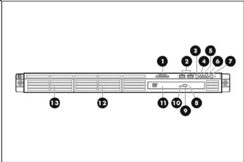
text_image
1 2 3 4 5 6 7 8 9 10 11 12 13| Item | Icon | Description |
| 1 | Serial label pull tab | |
| 2 | Front USB ports | |
| 3 | UID | Front unit identification (UID) button/LED |
| 4 | System health LED | |
| 5 | Embedded NIC activity/link LED | |
| 6 | HDD activity LED | |
| 7 | Power/standby button/LED | |
| 8 | Optical disc drive (ODD) manual eject hole | |
| 9 | ODD eject button | |
| 10 | ODD activity LED | |
| 11 | Optical disc drive | |
| Item | Icon | Description | |
| 12 | Hard disk drive (HDD) 2 | ||
| 13 | HDD | 1 |
NOTE: The location/availability of items 8 – 11 may vary depending on the model of the installed optical disc drive.
Rear panel
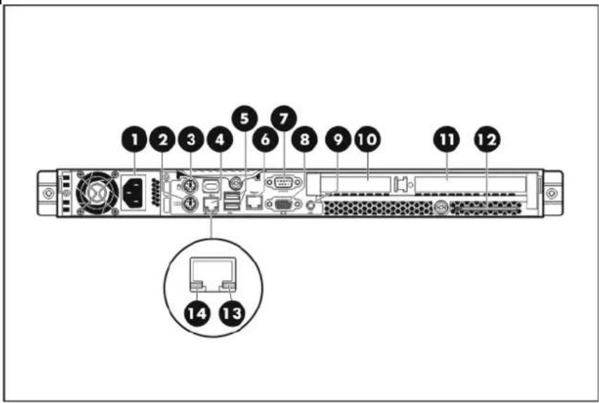
text_image
1 2 3 4 5 6 7 8 9 10 11 12 14 13| Item | Icon | Description |
| 1 | PSU cable socket | |
| 2 | PS/2 keyboard port | |
| 3 | PS/2 mouse port | |
| 4 / | Embedded NIC portMgmt | |
| 5 | Rear USB ports | |
| 6 | Mgmt | Management NIC (optional) |
| 7 | |0|0| | Serial port |
| 8 | |0| | Video port |
| 9 | UID | Rear UID button/LED |
| 10 | Expansion slot 2 cover | |
| 11 | Expansion slot 1 cover | |
| 12 | System screwdriver | |
| 13 | Embedded NIC link LED | |
| 14 | Embedded NIC activity LED |
System board
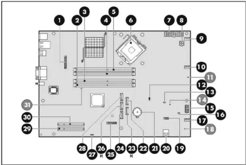
text_image
Labeled diagram of a computer motherboard with numbered components and connectors| Item | Component | code | Description |
| 1 CN6 DL120 G5 HP Lights-Out 100c module connector | |||
| 2 DIMM_CH2_B Channel 2 1 | ^st DDR II DIMM slot | ||
| 3 DIMM_CH2_D Channel 2 2 | ^nd DDR II DIMM slot | ||
| 4 DIMM_CH1_A Channel 1 1 | ^st DDR II DIMM slot | ||
| 5 DIMM_CH1_C Channel 1 2 | ^nd DDR II DIMM slot | ||
| 6 | CPU | Processor | |
| 7 PWR_CN 20-pin ATX system board power connector | |||
| 8 | CN4 | 4-pin ATX processor power connector | |
| 9 | CPU_FAN1 | Processor fan 1 connector | |
| 10 | CPU_FAN2 | Processor fan 2 connector | |
| 11 | LED1 | Processor fan failure LED | |
| 12 | JP5 | BIOS boot block jumper | |
| 13 | JP13 | NMI jumper | |
| 14 | LED3 | System/processor over temperature (OTP) LED | |
| 15 | CN8 Front panel board connector | ||
| 16 | CN26 | SAS LED cable connector | |
| 17 | SYSFAN System fan connector | ||
| 18 | LED2 System fan failure LED | ||
| 19 | CN9 Front USB port connector | ||
| 20 | SKT2 Internal USB connector | ||
| 21 | BAT1 | System | battery |
| 22 | HDD2 HDD 2 SATA cable connector | ||
| 23 | HDD4 Reserved SATA HDD cable connector | ||
| 24 | ODD1 ODD SATA cable connector | ||
| 25 | CN14 Trusted Platform Module (TPM) connector | ||
| 26 | HDD3 Reserved SATA HDD cable connector | ||
| 27 | JP7 Clear CMOS jumper | ||
| 28 | HDD1 HDD 1 SATA cable connector | ||
| 29 | Expansion_slot_1 Expansion slot 1 (for riser board) | ||
| 30 | Expansion_slot_2 Expansion slot 2 (for riser board) | ||
| 31 | LED4 DIMM failure LED | ||
System buttons and jumpers
UID button with LED indicator
Press this button to illuminate the LED indicator recessed underneath it. This is to mark a particular unit within a server group for purpose of identification during servicing or maintenance procedures.
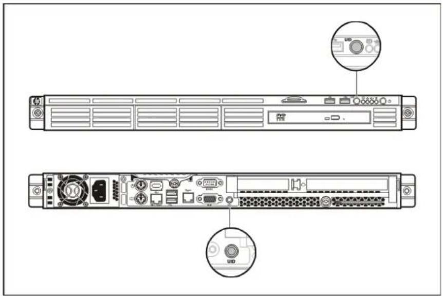
text_image
Technical diagram of a server rack with labeled ports and indicators, showing front and back views with UDD (User Interface) labels.System jumpers
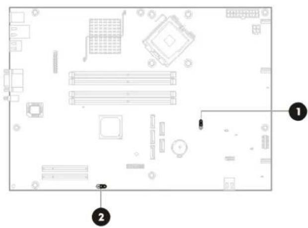
natural_image
Top-down schematic of a computer motherboard showing CPU socket, RAM slots, and memory components (no text or labels)| Item | Function | Status | Status | description |
| 1 | Boot block (JP5) | 1 – 2 | Normal operation (default) | |
| 2 – 3 | Configure BIOS | |||
| Removed | Access the boot block code | |||
| 1 – 2 | Normal operation (default) 2 CMOS clear (JP7) | |||
| 2 – 3 | Clear CMOS data |
Status LED indicators
The status LED indicators aid in problem diagnosis by indicating the status of system components and operations of the server.
External LED indicators
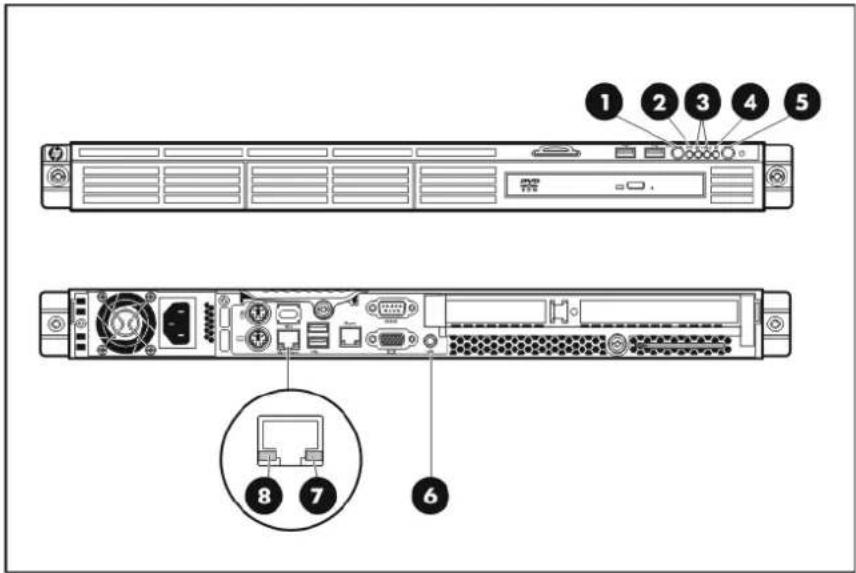
text_image
Diagram of a server rack with labeled ports and internal components, showing numbered parts for identification.| Item | Function | Status | Status | description |
| 1 and 6 | Unit identification | Blue A UID button has been pressed. | ||
| 2 | System health | Amber A pre-failure system threshold has been breached. | ||
| 3 | Embedded NIC activity/link | Solid green An active network link exists. | ||
| Flashing An ongoing network data activity exists. | ||||
| green | ||||
| Off The server is off-line. | ||||
| 4 | HDD activity | Green Ongoing hard drive activity | ||
| 5 | System power | Green Power on mode | ||
| Amber Standby mode | ||||
| bedded NIC link | Amber 10/100 Mbps connection | |||
| Green Gigabit connection | ||||
| 8 | Embedded NIC activity | Flashing green | Ongoing network activity | |
System board LED indicators
The system board LED indicators monitors the status of the hardware components. When any of these indicators are activated, the system health indicator on the front panel lights up.
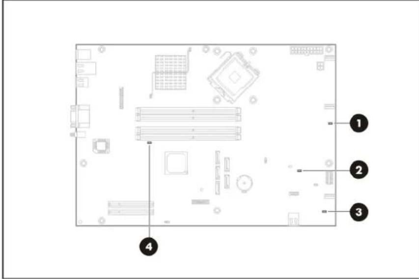
text_image
Diagram of a computer motherboard layout with numbered annotations pointing to specific components.| Item | Function | Status | Status | description |
| 1 | Processor fan failure | Green | Either fan 1 or fan 2, or both is defective. | |
| 2 | System/processor temperature (OTP) | over | Green | A system or processor temperature sensor has been breached. |
| 3 | System fan failure | Green | Fan 3 is defective. | |
| 4 | DIMM failure | Green | One or more of the installed DIMMs is defective. | |
System specifications
Hardware specifications
System unit
| Item | Attribute |
| Processor socket Intel LGA775 | |
| Processor support | Intel Celeron 400 SequenceIntel Pentium Dual-Core DesktopDual-Core and Quad-Core Intel XeonIntel Core 2 Duo Desktop |
| Core logic chipsets | Intel 3200 MCH (U8) - north bridge, core logic controllerIntel 82801IR ICH9R (U21) - south bridgeServerEngines Pilot 2 (U18) - BMC controller |
| Hardware monitoring chipset | Integrated in the ServerEngines Pilot 2 chip |
| LAN controller Broadcom NetXtreme 5722 Gigabit Ethernet Controller | |
| Memory controller Integrated in the Intel 3200 MCH | |
| Storage controller | SATA - Integrated in the Intel 82801IR ICH9RSAS - SAS controller board (optional) |
| VGA controller Integrated in the ServerEngines Pilot 2 chip | |
| I/O subsystem Two system board level expansion slots:Expansion slot 1 - Full-length/full-height PCI Express x8 slotExpansion slot 2 - Low-profile PCI Express x8 (x4 interconnect) slotThe PCI riser board assembly converts the functionality of the onboard PCI Express slots to a pair of slots positioned at a 90^ angle from the system board. | |
| Memory | Four DDR II slots8 GB maximum system memory (2 GB in each of the four DIMM slots)Interleaving mode supported |
| Media storage | Two LFF HDD bays supporting non-hot-plug SAS and SATA drivesOptical media device bay for slim type 12.7 mm SATA optical drive |
| I/O ports | Front panel - Two USB ports/Reopase port PS/Dekeyboxaser port PS twoUSB ports, and embedded NIC portInternal - One USB port for firmware update via USB drive key |
| Status LED indicators | Front panel – UID, system health, embedded NIC activity/link, HDD activity, and powerRear panel – Embedded NIC activity/link and UIDSystem board – processor fan, system fan, and DIMM failure; system/processor OTP |
| Server management | Dedicated system health indicatorOnboard hardware failure indicatorsManagement NIC function via the HP Lights-Out100c remote management card (optional) |
| Thermal solution | Three system fansOne processor heat sinkOne PSU fan |
Memory
| Item | Attribute | |
| Number of DIMM slots Four | ||
| Maximum memory capacity | 8 GB (2 GB in each of the four DIMM slots) | |
| Memory modes Single DIMM, two DIMMs (interleaving) and four DIMMs (full configuration) | ||
| Memory controller Integrated in the Intel | 3200 MCH | |
| DIMM specifications | ||
| Size 512 MB, 1 GB, and 2 GB | ||
| Speed | 800 MHz | |
| Type PC2-6400 ECC RoHS | ||
Processor
Intel Celeron 400 Sequence
| Item | Specification | |
| Processor number L420 L440 | ||
| CPU speed 1.6 GHz 2.0 GHz | ||
| Bus speed 800 MHz 800 MHz | ||
| Bus/core ratio 8 10 | ||
| L2 cache size 512 KB 512 KB | ||
| L2 cache speed 1.6 GHz 2.0 GHz | ||
| Manufacturing technology 65 nm 65 nm | ||
| Core stepping | A1 | A1 |
| CPUID string | 10661h | 10661h |
| Thermal design power | 35W | 35W |
| Thermal specification | 60.4°C | 60.4°C |
| VID voltage range | 1.0V-1.3375V | 1.0V-1.33375V |
Intel Pentium Dual-Core Desktop
| Item | Specification |
| Processor number | E2160 |
| CPU speed | 1.8 GHz |
| Bus speed | 800 MHz |
| Bus/core ratio | 9 |
| L2 cache size | 1 MB |
| L2 cache speed | 1.8 GHz |
| Manufacturing technology | 65 nm |
| Core stepping | M0 |
| CPUID string | 06FDh |
| Thermal design power | 65W |
| Thermal specification | 73.2°C |
| VID voltage range | 0.85V–1.5V |
Intel Xeon Dual-Core
| Item | Specification | |||||
| Processor | number | E3110 | 3065 | 3075 | 3085 | |
| CPU speed | 3.0 GHz | 2.33 GHz | 2.66 GHz | 3.0 GHz | 3.1 GHz | |
| Bus speed | 1333 MHz | 1333 MHz | 1333 MHz | 1333 MHz | ||
| Bus/core | ratio | 9 | 7 | 8 | ||
| L2 cache size | 6 MB | 4 MB | 4 MB | 4 MB | 6 MB | |
| L2 cache speed | 3.0 GHz | 2.33 GHz | 2.66 GHz | 3.0 GHz | 3.16 GHz | |
| Manufacturing technology | 45 nm | 65 nm | 65 nm | 65 nm | 45 nm | |
| Core stepping | C0 | G0 | G0 | G0 | E0 | |
| CPUID string | 10676h | 06FBh | 06FBh | 06FBh | 1067 Ah | |
| Thermal design power | 65W | 65W | 65W | 65W | 65W | |
| Thermal specification | 72°C | 72°C | 72°C | 72°C | 72°C | |
| VID voltage range | 1.225V-0.956V | 0.85V-1.3625V | 0.85V-1.3625V | 0.85V-1.3625V | 1.3625V | |
Intel Xeon Quad-Core
| Item | Specification | ||
| Processor number | X3210 | X3320 | X3350 |
| CPU speed | 2.13 GHz | 2.5 GHz | 2.66 GHz |
| Bus speed | 1066 MHz | 1333 MHz | 1333 MHz |
| Bus/core ratio | 8 | 7.5 | 8 |
| L2 cache size | 8 MB | 6 MB | 12 MB |
| L2 cache speed | 2.13 GHz | 2.5 GHz | 2.66 GHz |
| Manufacturing technology | 65 nm | 45 nm | 45 nm |
| Core stepping | G0 | M1 | C1 |
| CPUID string | 06FB | 0677 | 0677 |
| Thermal design power | 95W | 95W | 95W |
| Thermal specification | 62°C | 71°C | 71°C |
| VID voltage range | 1.100V-1.372V | 1.100V-1.372V | 1.100V-1.372V |
| Item | Specification | ||||
| Processor | number | X3220 | X3330 | X3360 | |
| CPU speed | 2.40 | 2.66 | 2.83 | ||
| Bus speed | 1066 GHz | 1333 GHz | 1333 GHz | ||
| Bus/core | ratio | 9 | 8 | 8.5 | |
| L2 cache size | 8 MB | 6 MB | 12 MB | ||
| L2 cache speed | 2.4 GHz | 2.66 GHz | 2.83 GHz | ||
| Manufacturing technology | 65 nm | 45 nm | 45 nm | ||
| Core stepping | G0 | R0 | C1 | ||
| CPUID string | 06FBh | 1067Ah | 10676h | ||
| Thermal design power | 95W | 95W | 95W | ||
| Thermal specification | 62°C | 71°C | 71°C | ||
| VID voltage range | 1.100V-1.372V | 1.3625V | 0.962V-1.237V | ||
Intel Core 2 Duo Desktop
| Item | Specification |
| Processor number | E4600 |
| CPU speed | 2.4 GHz |
| Bus speed | 800 MHz |
| Bus/core ratio | 12 |
| L2 cache size | 2 MB |
| L2 cache speed | 2.4 GHz |
| Manufacturing technology | 65 nm |
| Core stepping | M0 |
| CPUID string | 06FDh |
| Thermal design power | 65W |
| Thermal specification | 73.3°C |
| VID voltage range | 1.162V-1.312V |
Power supply unit
| Item | Attribute | |
| Model | DPS-350WB | A |
| Type | 350W | |
| Dimensions | ||
| Height | 40 mm (1.57 in.) | |
| Depth | 240 mm (9.46 in.) | |
| Width | 106 mm (4.18 in.) | |
| Weight (approximate) 1.73 kg (3.81 lb) | ||
| Input requirements | ||
| Rated input voltage | 90–264 VAC | |
| Normal line voltage | 115 VAC, 230 VAC | |
| Line frequency 47–63 Hz | ||
| Rated input current | Load 6A at 100–240 VAC, 3A at 230 VAC | |
| Inrush current 150A | ^2 sec | |
| Power supply output power | ||
| Rated steady state power | 350W | |
| Maximum peak power | None | |
| Operating conditions | ||
| Temperature | +10–48°C (+50 –118.4°F) | |
| Humidity (non-condensing) | 5–85% | |
Software specifications
| Item | Attribute |
| Network operating system (NOS) support | Microsoft Windows Server 2003 R2 Enterprise EditionMicrosoft Windows Server 2003 R2 Enterprise x64 EditionMicrosoft Windows Server 2003 R2 Standard EditionMicrosoft Windows Server 2003 R2 Standard x64 EditionMicrosoft Windows Server 2003 Web EditionMicrosoft Windows Server 2008 Enterprise EditionMicrosoft Windows Server 2008 Enterprise x64 EditionMicrosoft Windows Server 2008 Standard EditionMicrosoft Windows Server 2008 Standard x64 EditionMicrosoft Windows Server 2008 Web EditionRed Hat Enterprise Linux 5 (x86)Red Hat Enterprise Linux 5 (AMD64/EM64T)Red Hat Enterprise Linux 4 (x86)Red Hat Enterprise Linux 4 (AMD64/EM64T)SUSE Linux Enterprise Server 10 (x86)SUSE Linux Enterprise Server 10 (AMD 64/EM64T)SUSE Linux Enterprise Server 9 (x86)SUSE Linux Enterprise Server 9 |
| System diagnostics | HP Insight DiagnosticsArray Diagnosti c UtilityIPMI Event LogPhoenix BIOS Setup Utility |
Physical specifications
| Item | Attribute |
| System board dimensions | |
| Length | 330.20 mm (13.0 in.) |
| Width | 228.6 mm (9.0 in.) |
| Server dimensions | |
| Height | 43.2 mm (1.70 in) |
| Width | 448.0 mm (17.64 in) |
| Depth | 682.0 mm (26.85 in) |
| Server weight (maximum configuration, approximate) | |
| Basic configuration (one hard drive installed) | 14.7 kg (32.41 lb) |
| Fully loaded configuration (both HDD bays occupied) | 15.45 kg (34.06 lb) |
Environmental specifications
| Item | Attribute |
| Temperature range | |
| Operating | 10-35°C (50-95°F) |
| Non-operating | -30-60°C (-22-140°F) |
| Humidity (non-condensing) | |
| Operating | 10-90% RH |
| Non-operating | 10-95% RH |
| Altitude | |
| Operating | 0-10,000 feet |
| Non-operating | 0-30,000 feet |
| Acoustic noise | |
| Idle, minimum (fixed disk drives spinning) | L Wad (BELS) - 6.19 L pA (dBA) - 43.5 |
| Operating, minimum (random seeks to fixed disk drives) | L Wad (BELS) - 6.20 L pA (dBA) - 43.6 |
Index
A
AC power
power-down procedure, 30
status indicator, 93
air baffle
removing, 47
B
Baseboard Management Controller. See BMC
Basic Input/Output System. See system BIOS
battery
location, 59
replacement warnings, 59
replacing, 60
BMC
specification, 95
boot block, 82
boot sequence
configuring, 80
default settings, 80
boot-time diagnostic screen
information display, 81
viewing, 81
C
cable management, 31
CMOS clear jumper, 84
CMOS RAM
clearing, 85
definition, 75
POST error messages, 86
resetting, 85
console redirection, 78
core logic chipset
north bridge, 95
south bridge, 95
CSR, 5
customer self repair. See CSR
D
diagnostics
Array Diagnostic Utility, 73
HP Insight Diagnostics, 73
IPMI Event Log, 73
Phoenix BIOS software, 74
drive bay configuration
data cable management, 34
hard drives, 36
optical disc drive, 42
power cable connections, 36
system drive bays, 34
E
electrostatic discharge. See ESD
embedded NIC
front panel LED, 93
rear panel LED, 93
embedded NIC port
MAC address, 77
environmental specifications
acoustic noise, 103
altitude, 103
relative humidity, 103
temperature, 103
ESCD
clearing configuration data, 78
definition, 78
ESD
precautions, 29
work area recommendations, 29
expansion board
PCI riser board assembly, 55
system board expansion slots, 54
expansion boards
installation guidelines, 57
installing, 57
PCI-X support, 64
Extended System Configuration Data. See ESCD
F
front panel, 88
G
General Help window, 76
H
hard drive
configuring, 78
installation guidelines, 37
installing, 37
removing, 37
status indicator, 93
storage controller, 95
supported drives, 36
hardware configuration
boot-time diagnostic screen, 81
ESD damage prevention, 29
expansion board, 54
IPMI card, 65
memory, 52
opening the server, 32
PCI-X riser board, 64
Phoenix BIOS Setup Utility, 74
post-installation procedure, 30
power supply unit, 69
pre-installation procedure, 29
processor, 46
references, 27
SAS controller board, 61
SAS HDD cable, 62
SAS LED cable, 63
symbols in equipment, 28
system battery, 59
system drives, 34
system fans, 67
tools, 27
warnings/precautions, 27
hardware monitoring
system health indicator, 93
heat sink
installing, 51
removing, 47
HP
contact information, 26
technical support, 26
|
I/O ports
front panel, 88
listing, 95
rear panel, 89
I/O subsystem, 95
illustrated parts catalog
mechanical components, 16
system components, 21
installation guidelines
expansion boards, 57
hard drive, 37
optical disc drive, 42
IPMI card
installing, 66
part number, 22
IPMI Event Log
diagnostic, 73
viewing, 73
Item Specific Help panel, 76
L
legend bar, 76
Lights-Out 100c remote management card
connector, 89
installing, 66
overview, 65
M
MAC address, 77
management NIC
Lights-Out 100c option, 65
module connector, 89
mechanical components, 16
Media Access Control. See MAC address
memory
DIMM part numbers, 22
DIMM slots location, 52
installation guidelines, 52
installing, 53
memory size value, 77
specifications, 96
memory controller, 95
multi-boot support, 80
N
network operating system. See NOS support
NOS support, 101
0
ODD backplane board
installing, 45
removing, 43
onboard controllers
BMC, 95
LAN, 95
memory controller, 95
storage controller, 95
VGA, 95
optical disc drive
cable connection, 35
installation guidelines, 42
part numbers, 22
replacing, 43
supported drives, 42
P
PCI riser board assembly
description, 55
PCI-X support, 64
reinstalling, 56
removing, 56
PCI-X riser board
installing, 64
Phoenix BIOS Setup Utility
"Run Setup" message, 74
Advanced menu, 78
Boot menu, 80
Boot-time Diagnostic Screen, 81
clearing the CMOS RAM, 84
CMOS RAM, 75
Exit menu, 81
General Help window, 76
Item Specific Help panel, 76
legend bar, 76
loading system defaults, 84
Main menu, 77
navigation keys, 76
non-user-configurable field, 76
overview, 74
recording Setup values, 83
running, 75
Security menu, 79
supervisor password, 79
user-configurable field, 76
Phoenix BIOS software
overview, 74
POST, 85
physical specifications
server, 102
system board, 102
POST
error messages, 85
overview, 85
running, 85
troubleshooting, 87
power fluctuations, caution, 30
power supply unit
cable connections, 36
disconnecting cables, 70
installing, 71
removing, 71
replacement warnings, 69
power-down procedures, 30
Power-On Self-Test. See POST
Preboot Execution Environment. See PXE
primary access panel
part number, 17
removing, 32
processor
configuring, 78
installation guidelines, 46
installing, 50
part numbers, 22
removing, 49
socket location, 46
technical specifications, 97
thermal compound, 50
PSU. See power supply unit
part number, 22
specifications, 100
PXE, 80
R
rear panel, 89
recording Setup values
manual record, 83
s
SAS controller board
installing, 61
part number, 23
SAS hard drive
cable connections, 35
installing, 37
part number, 22
SAS controller board, 61
SAS HDD cable, 62
SAS LED cable, 63
SAS HDD cable
connecting, 62
connection, 35
part number, 22
SAS LED cable
connecting, 63
connection, 35
part number, 22
SATA data cable
connections, 35
SATA hard drive
cable connections, 35
installing, 37
part number, 22
SATA HDD cable
part number, 22
secondary access panel
part number, 17
removing, 33
server management
configuring, 78
specification, 96
status LED indicators, 93
software specifications
NOS, 101
system diagnostics, 101
spare parts
mechanical components, 16
storing, 29
system components, 21
transporting, 29
standby mode
activating, 30
effects, 30
status indicator, 93
status LED indicators
embedded NIC, front, 93
embedded NIC, rear, 93
hard drive activity, 93
power, 93
system board, 94
system health, 93
UID, front, 93
supervisor password
changing, 79
removing, 80
resetting, 80
setting, 79
system BIOS
boot block, 82
overview, 74
recovering, 82
updating, 82
system board
dimensions, 102
layout, 90
part numbers, 22
status LED indicators, 94
system components, 21
front panel, 88
rear panel, 89
system board, 90
system covers
primary access panel, 32
secondary access panel, 33
system date
POST error message, 87
setting, 77
system fans
cable connections, 67
device number, 67
installing, 68
part number, 22
removing, 68
system health
critical errors, 93
external indicator, 93
pre-failure component error, 93
system jumpers, 91
boot block, 82
CMOS clear, 84
system time
POST error message, 87
setting, 77
T
technical specifications
environmental, 103
hardware, 95
memory, 96
physical, 102
power supply unit, 100
processor, 97
software, 101
thermal compound, 50
thermal solution, 96
U
UID. See unit identification
uninterruptible power supply. See UPS
unit identification
function, 91
LED indicator, front, 93
UPS, 30
V
VGA controller, 95
W
warranty, 5