CS9GMNHA - Oven SMEG - Free user manual and instructions
Find the device manual for free CS9GMNHA SMEG in PDF.


User questions about CS9GMNHA SMEG
0 question about this device. Answer the ones you know or ask your own.
Ask a new question about this device
Download the instructions for your Oven in PDF format for free! Find your manual CS9GMNHA - SMEG and take your electronic device back in hand. On this page are published all the documents necessary for the use of your device. CS9GMNHA by SMEG.
USER MANUAL CS9GMNHA SMEG
3.1 Our environmental care 8
3.2 Your environmental care 8
4.GETTOKNOWYOURAPPLIANCE....9
4.1 Description of the controls on the front panel 10
- AVAILABLE ACCESSORIES 11
5.1 Using the rack or tray 11
5.2 Using the support rack 12
5.3 Using the rotisserie rod (on some models only) 12
5.4 Using the reduction pan stands 12
5.5 Using the Teppanyaki plate (on some models only) 12
- USING THE COOKING HOB 13
6.1 General warnings and advice 13
6.2 Lighting the hob burners 13
6.3 Practical hints for using the hob burners 13
6.4 Cookware diameters 13
- USING THE OVEN 14
7.1 Before using the appliance 14
7.2 Oven runners 14
7.3 Storage compartment (on some models only) 14
7.4 Cooling system 14
7.5 Internal light 14
7.6 General warnings and advice for use 15
7.7 Electronic programmer (on some models only) 16
- COOKING WITH THE OVEN 18
8.1 Cooking advice and instructions 19
8.2 Cooking information table 20
9.CLEANINGANDMAINTENANCE....21
9.1 Cleaning stainless steel 21
9.2 Ordinary daily cleaning 21
9.3 Food stains or residues 21
9.4 Cleaning the Teppanyaki plate (on some models only) 21
9.5 Cleaning the door glazing 21
9.6 Cleaning the door seal 21
9.7 Cleaning the cooking hob parts 22
9.8 Cleaning the oven 22
- EXTRAORDINARYMAINTENANCE....23
10.1 Removing the door 23
10.2 Replacing the light bulb 23
10.3 Removing the door seal 23
- INSTALLATION 24
11.1 Clearances above and around domestic appliances 24
11.2 Combustion gas discharge 24
11.3 Gas connection 25
11.4 Room ventilation 25
11.5 Extraction of the combustion products 25
11.6 Electrical connection 26
11.7 Positioning the skirt (on some models only) 27
11.8 Positioning and levelling the appliance 27
11.9 C91GMXAT Wall mounting brackets 28
11.10 C9GMXA Wall mounting brackets 29
11.11 Wall fixing 30
INSTRUCTIONSFORTHEUSER:thesecontainuseradvice,thedescriptionofthecontrolsand thecorrectproceduresforcleaningandmaintenanceoftheappliance.
INSTRUCTIONS FOR THE INSTALLER: these are intended for the authorized person who must install the appliance, setitfunctioning and carryoutaninspection test.

Furtherinformationabouttheproductscanbefoundatwww.smeg.com
1.INSTRUCTIONSFORUSE

Thismanualisanintegralpartoftheappliance.Itmustbekeptinitsentiretyandinanaccessibleplace forthewholeworkinglifeoftheappliance.Werecommendreadingthismanualandallinformationit containscarefullybeforeusingtheappliance.Installationmustbecarriedoutbyqualifiedpersonnelin accordancewiththestandardsinforce.Thisapplianceisintendedfordomesticuseandconformstothe EC directives currently in force. The appliance has been built to carry out the following functions: cookingandheatingupfood;allotherusesareconsideredunsuitable.

These instructions are valid only for the destination countries whose identifying symbols are included on the cover of this manual.

Neverobstructtheopeningsandslotsprovidedforventilationandheatdispersal;thismaycause malfunctions.
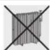
Donotusethisapplianceforheatingrooms.

The identification plate with technical data, serial number and brand name is located in an exposed position either in the drawer (where present) or on the back of the appliance. A copy of the identification plate is included in the booklet. It should be applied to an adjacent surface, ie. cupboard.

Before the appliance is put into operation, all labels and protective films applied on external surfaces must be removed.

Donotusemetallicspongesorsharpscrapers:theywilldamagethesurfaces.Usenormalnon-abrasive productsandawoodenorplastictoolifnecessary.Rinsethoroughlyanddryusingasoftcloth.Donot allowresiduesofsugaryfoods(suchasjam)tosetinsidetheoven.Iflefttosetfortoolong,theymight damagetheenanelliningoftheoven.

Donotuseplastickitchenwareorcontainers. The hightemperaturesinsidetheovencouldmeltthe plastic,damagingtheappliance.


Alwayscheckthatthecontrolknobsareinthe"zero"(off)positionwhenyoufinishusingtheappliance.
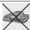
Donotusesealedtinsorcontainersintheappliance. Overpressure may occur inside the containers during cooking, creating dangerofexplosion.

Donotcoverthebottomoftheovenwithaluminiumortinfoilsheetsduringcookinganddonotplace pansortraysonittoavoiddamagetotheenamelledsurface.

Neverplacesaucepanswithbaseswhicharenotperfectlyflatandsmoothonthehob.Unstable cookwarecanleadtosalding.

Donotrestanyweightorsitontheopendooroftheappliance.Excessiveweightmayjeopardiseits stability.

The appliance becomes very hot during use. Suitable heat-proof gloves should be worn for all operations.

Donotusethehobifpyrolysis(wherepresent)istakingplaceinsidetheoven.

If you intend to go away for a prolonged period of time, closet remains gastaporthegascylindertap.

Takecarethatnoobjectsarestuckinthedooroftheoven.

Donotopenthestoragecompartment(wherepresent)whentheovenisonandstillhot. The temperaturesinsideitmaybeveryhigh.
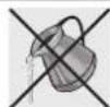
If the surfaces are still very hot during cooking, donot pour water directly onto the trays. The steam could cause severe burns and damage enamelled surfaces.

Allcookingoperationsmusttakeplacewiththedoorclosed. Thedissipationofheatmaycausehazards.

Themanufacturerdeclinesallresponsibilityfordamagetopersonsorthingscausedbynon-observanceoftheaboveprescriptionsorbyinterferencewithanypartoftheapplianceorbytheuseofnon-originalspareparts.
2.SAFETYPRECAUTIONS
Consult the installation instructions for safety standards one electrical gas appliances and for ventilation functions. In your interests and for yoursafety the law require that the installation and servicing of all electrical and gas appliances be carried out by qualified personnel in accordance with the standards in force. Our approved installers guarantee satisfactory job. Gasorelectrical appliances must always be uninstalled by suitably skilled people.

Beforeconnectingtheappliancetothepowergrid,checkthedataontheplateagainstthedataforthe griditself.

If the appliance is installed on a raised platform, secure it using suitable fastenings systems.

Beforecarryingoutinstallation/maintenancework,makesurethattheapplianceisdisconnectedfrom thepowergrid.

If cooking appliances are installed in motor vehicles (forexample, campervans, caravansetc.), they must only be used when the vehicle is stationary.

Where this appliance is installed in marine craft or in caravans, it shall not be used as a space heater.

Installtheappliancesothatwhenopeningthedrawersordoorsofunitspositionedatthelevelofthehob thereisnopossibilityofmakingcontactwithpanspositionedontopofit.

Immediately after installation, carry out a quick test on the appliance following the instructions provided later in this manual. Should the appliance not function, disconnect from the powers supply and call the nearest technical assistance centre.

Theplugtobeconnectedtothepowersupplycableanditssocketmustbeofthesametype and conformtothestandardsinforce. Thesocketmustbeaccessibleaftertheappliancehasbeeninstalled. Neverdisconnecttheplugbypullingonthecable.

If the powers supply cable is damaged, contact the technical assistance centre immediately and they will replace it.

The appliance must be connected to earth in compliance with the electrical systems safety standards.

During usethe appliance and its accessible parts become every hot. Take care nevertotouch the heating elements. Keep children younger than 8 away from the appliance, unless under continuous supervision.

Neverputinflammableobjectsintheoven:theycouldbeaccidentallyignitedandcausefires.

The appliance is intended for use by adults. Donot allow children to go near or play with it.

This appliancemaybeusedbychildrenfromtheageof8andbypeopleofreducedphysicalandmentalabilityorlackinginexperienceandknowledge,providedtheyaresupervisedorinstructedonthesafeuseoftheapplianceandiftheyunderstandtheassociatedrisks.Donotallowchildrentoplaywiththe appliance.Donotallowunsupervisedchildrentoperformcleaningormaintenanceoperations.

Neverattempttorepairtheappliance.Allrepairsmustbecarriedoutbyanauthorisedtechnicianorat anauthorisedservicecentre.Theimproperuseoftoolscancausehazards.
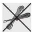
Donotmodifythisappliance.
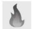
Donotuseorstoreflammablematerialsintheappliancestoragedrawerornearthisappliance.

This appliancemustnotbecontrolledusinganexternaltimerorremotecontrolsystem.
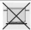
Beawareofhowrapidlythecookingzonesheatup.Donotplaceemptysaucepansontheheat.Danger ofoverheating.
Fatsandoilscancatchfireiftheyoverheat.Youarethereforerecommendednottoleavetheappliance unattendedwhilepreparingfoodscontainingoilsorfats.Iffatsoroilscatchfire,neverputwateronthem. Placethelidonthesaucepanandturnoffthecookingzone.

Take care when using additionalelectrical appliances in the kitchen (e.g. blender, toaster etc.). Connection cables must not come into contact with hot cooking zones.

Donotusesteamjetsforcleaningtheappliance. Thesteamcouldreachtheelectronics,damagingthemandcausingshort-circuits.

Donotsprayanysprayproductsnearthehouseholdappliancewhileitisinoperation.Donotusespray productswhiletheapplianceisstillhot.Thegasescontainedinspraycansmaycatchfire.

Themanufacturerdeclinesallresponsibilityfordamagetopersonsorthingscausedbynon-observanceoftheaboveprescriptionsorbyinterferencewithanypartoftheapplianceorbytheuseofnon-originalspareparts.
3. ENVIRONMENTAL CARE
3.1 Ourenvironmentalcare
Adequateselectivecollectionforthesubsequentforwardingofthedecommissionedproducttorecycling, treatmentandecologicallycompatibledisposalcontributestoavoidingpossiblenegativeeffectsonthe environmentandonhealthandpromotestherecyclingofthematerialsofwhichthepplianceconsists. Illicitdisposaloftheproductbytheuserwillleadtotheapplicationofadministrativesanctions.
The appliance does not contain substances in quantity sufficient to be considered hazardous to health and the environment, in accordance with current Europe and directives.
3.2 Yourenvironmentalcare
Ourappliancesarepackedinnon-pollutingmaterials,whicharethereforecompatiblewiththe environmentandrecyclable.Pleasehelpbydisposingofthepackagingcorrectly.Youcanobtainthe addressesofcollection,recyclinganddisposalcentresfromyourretailerorfromthecompetentlocal organisations.

Donotdiscardthepackagingoranypartofit,orleaveitunattended.Itcanconstitutea suffocationhazardforchildren,especiallytheplasticbags.
Youroldappliancealsoneedstobedisposedofcorrectly.
Important: hand over your appliance to the local agency authorised for the collection of electrical appliances no longer in use. Correct disposal enables intelligent recovery of valuable materials.
Before disposing of your appliance it is important to remove doors and leave shelves in the same position as for use, to ensure that children cannot accidentally become trapped inside during play. It is also necessary to cut the connecting cable to the power supply network, removing it along with the plug.
text_image
Labeled diagram of a kitchen oven with numbered parts for identification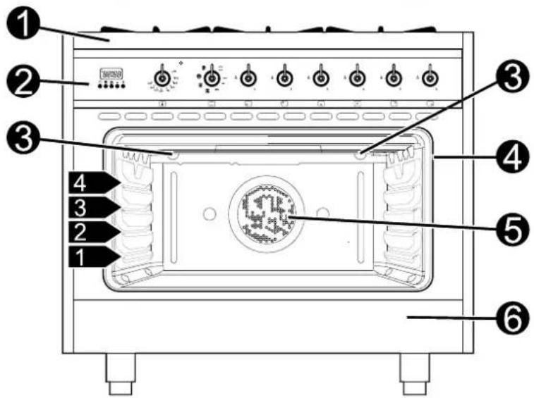
text_image
Diagram of a microwave oven with numbered parts for identification1 Cookinghob
2 Controlpanel
3 Ovenlight(doubleonsomemodels)
4 Ovenseal
5 Fan
6 Storagecompartment
Rack/traysupportframe
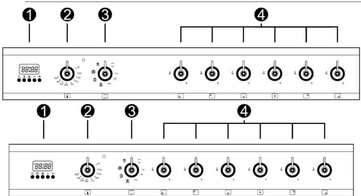
4.1 Description of the control on the front panel
text_image
① ② ③ ④ 88:88 200° 246° 275° 300° 325° 350° 375° 400° 425° 450° 475° 500° 525° 550° 575° 600° 625° 650° 675° 700° 725° 750° 775° 800° 825° 850° 875° 900° 925° 950° 975° 1000° 1025° 1050° 1075° 1100° 1125° 1150° 1175° 1200° 1225° 1250° 1275° 1300° 1325° 1350° 1375° 1400° 1425° 1450° 1475° 1500° 1525° 1550° 1575° 1600° 1625° 1650° 1675° 1700° 1725° 1750° 1775° 1800° 1825° 1850° 1875° 1900° 1925° 1950° 1975° 2000° 2025° 2050° 2075° 2100° 2125° 2150° 2175° 2200° 2225° 2250° 2275° 2300° 2325° 2350° 2375° 2400° 2425° 2450° 2475° 2500°4.1.1 Programmingclock
1 The programming clock allow stodisplay the current time to set at timer or a programmed cooking operation.
4.1.2 Temperature selection knob
2 Thecookingtemperatureisselectedbyturningtheknobclockwisetotherequired setting, betweenthemaximumandthemminimumsettings. Theindicatorlightcomes ontoindicate that theovenisheatingup. Whenthislightgoesout, thepreset heatingtemperaturehasbeenreached. Whenthelightflashesregularly, itmeans that the temperatureinsidetheoveniskeptsteadyonthesetlevel.

4.1.3 Functionselectionknob
3 Theoven'svariousfunctionsaresuitablefordifferentcookingmodes. After selectingtherequiredfunction,setthecookingtemperatureusingthethermostat knob.Formoreinformationoncookingfunctions,see: "8.COOKINGWITHTHEOVEN".

4.1.4Hobburnerscontrolknob
4 Tolighttheflame, presstheknobandturnitanti-clockwisetothemaximumflame symbol( ).oadjusttheflame, turntheknobtothezonebetweenthemaximum ( )andtheminimum( )settings. Toturnofftheburner, turntheknobtothe position. (Theadjacentsymbolindicatesthefrontleftburner).


5. AVAILABLE ACCESSORIES
NOTE: Somemodelsarenotprovidedwithallaccessories.
Rack:
usefulforholding cookingcontainers.
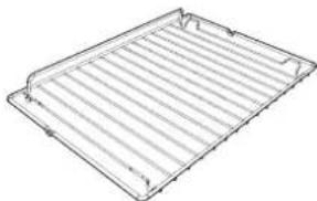
natural_image
Line drawing of a rectangular metal grate or rack with slats (no text or symbols)Trayrack:
itcanbecombinedwith theoventray.
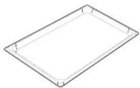
natural_image
Simple line drawing of a rectangular tray or container with rounded corners and a flat top (no text or symbols)Rotisserieframe(on somemodelsonly):
supportstherotisserie rod.
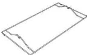
natural_image
Simple line drawing of a rectangular frame with no text or symbolsRotisserierod(on
somemodelsonly):for cookingchickenandall foodswhichrequire uniformcookingover theirentiresurface.

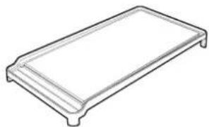
Teppanyakiplate(onsomemodelsonly):
Usefulforcookingmeat,fishandvegetablesdirectlyontheplatewithout addingfatsoroils,stayingtruetothetraditionofJapanesecuisinethatseeks toexaltthenaturalflavoursandaromasoffoodensuringlightnourishment whilepreservingallnutritionalelements.
natural_image
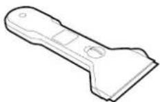
Line drawing of a rectangular electronic component or tray (no text or symbols)Scraper(onsome modelsonly):
Usefulforcleaningthe Teppanyakiplate.Donot useonothersurfaces.
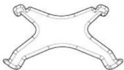
Reductionpanstand:
usefulwhenusingsmall pans.

Theovenaccessoriesintendedtocomeintocontactwithfoodaremadeofmaterialsthatcomplywith theprovisionsofcurrentlegislation.

Accessoriesavailableonrequest:
•OriginalsuppliedandoptionalaccessoriesmaybeorderedfromanyAuthorisedAssistanceCentre.
•Useonlyoriginalaccessoriessuppliedbythemanufacturer.
5.1 Usingtherackortray
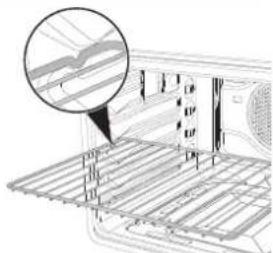
Theracksortraysareequippedwithamechanicalsafetylockwhichprevents themfrombeingtakenoutaccidentally.Toinserttherackortraycorrectly,check thatthelockisfacingdownwards(asshowninthefigureattheside).
Toremovetherackortray, liftthefrontslightly.
Themechanicallock(orthoextensionpiecewherepresent)mustalwaysface thebackoftheoven.
natural_image
Technical line drawing of a mechanical assembly with a magnified inset showing internal components (no text or symbols)
Gentlyinsertracksandtraysintotheovenuntiltheycometoastop.

Inmodelswithguides, cleanthetrays before using them for the first time. Cleaning will remove any manufacturing residues, which may otherwise scratch these of the ovencavity when trays are being inserted.
5.2 Using the support track
natural_image
Exterior view of a rectangular metal grate with two vertical slats (no text or symbols)5.3 Usingtherotisserierod(onsomemodelsonly)
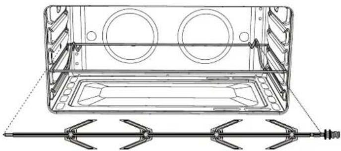
When cooking with therotisserie, position therodframe on these second runner (see 7.2 Ovenrunners). Then prepare therotisserie rod with the food, using the clip forks provided.
Screwonthehandleprovidedsothatyou canhandletherodwiththefoodonit readily.
Afterhavingpreparedtherotisserierodwith thefood,positionitontheguideframeas
natural_image
Technical line drawing of a rectangular enclosure with circular cutouts and a diagonal tool inserted into the base (no text or symbols)showninthefigure.Inserttherodintotheholesothatitconnectswiththerotisseriemotor.Makesure thatthecontouredpartisplacedcorrectlyontheguideframe.
PRECAUTIONS:
•Grillingprocessesmustneverlastmorethan60minutes.
•Inmodelswithanelectricoven,theovendoormustbeclosedduringgrillcookingoperations.
- To prevent hazardous overheating, the appliance's glass lid must always be raised when using the ovenogrill.
- Accessible parts may be very hot during and after use of the grill; keep children well away from the appliance.
- Duringrotisseriecookingoperations,oneofthepanssuppliedwiththecookersshouldbeplacedon thebottomoftheoven,onthebottomrunners,tocollectanygreaseandfatproduced.
- Whenusingtheoven,removeallunusedtraysandracksfromitsinterior.
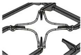
5.4 Usingthereductionpanstands
Thereductionpanstandsshouldbeplacedontopofthehobpanstandsasshownintheadjacentfigure.Makesuretheyarestable. TheWOKpanstandshouldonlybeusedwhencookingwithawok.
natural_image
Pure mechanical linkage diagram without any text, numbers, or symbols5.5 Using the Teppanyakiplate (onsomemodelsonly)
text_image
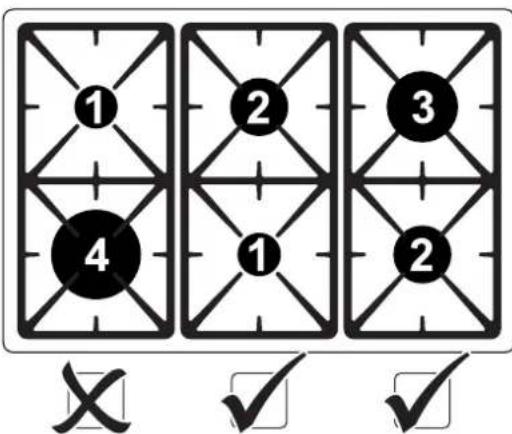
1 2 3 4 1 2 X ✓ ✓•The Teppanyakiplatecanbeusedexclusivelyonthe pairofcentralorright-handburnersofthehob;
•The Teppanyakiplates should be positioned in place of therack;
•Theplatemustnotbeusedformorethan60minutes;
•Theburnersundertheplatecanbelitatthesametime tothemaximumsettingfornomorethan15minutes. After this time they should be set at the minimum setting;
- Afteruse, it is advisable to wait for at least 15 minutes before removing the accessory from the appliance.
Beforelightingthehobburners, makesurethattheflame-spreadercrownsarecorrectlypositionedin theirhousingswiththeirrespectiveburnercaps.
6.2 Lighting the hobburners

Alltheappliance'scontrolandmonitoringdevicesarelocatedtogetheronthefrontpanel.Theburner controlledbyeachknobisshownnexttotheknob.Theapplianceisequippedwithanelectroniclighter. Simplypresstheknobandturnitanti-clockwisetothemaximumflamesymboluntiltheburnerlights.If theburnerdoesnotlightinthefirst15seconds,turntheknobto"0"andwait60secondsbeforetrying again.Afterlighting,keeptheknobpresseddownforafewsecondstoallowthethermocoupletoheat up.Theburnermaygooutwhentheknobisreleased:inthiscase,thermocouplehasnotheatedup sufficiently.
Waitafewmomentsandrepeattheoperation,keepingtheknobpressedforlonger.
If the burners should go out accidentally, as safety device will be tripped, cutting off the gassupply, even if the gastapis open. In this case, turn the knob to the OFF position and wait at least 60 seconds before trying to light the burner again.
6.3 Practical hints for using the hobburners
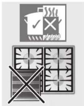
Forbetterburnerefficiencyandtominimisegasconsumption:usepanswith lidsandofasuitablesizefortheburner,sothattheflamesdonotreachupthe sidesofthepan(seeparagraph"6.4Cookwarediameters").Oncethecontents cometotheboil,turndowntheflamefarenoughtoensurethattheliquiddoes notboilover.Ifanyliquiddoesboiloverorspill,removetheexcessfromthe hob.
Topreventburnsordamagetothehobduringcooking,allpansorgriddles mustbeplacedinsidetheperimeterofthehob.Allpansmusthavesmooth,flat bottoms.
If the flame accidentally goes out, turn off the control knob and wait at least 1 minute before retrying to light the burner.
natural_image
Illustration of a food safety symbol with crossed-out grid, no text or symbols present
Takethegreatestcarewhenusingfatsoroilssincetheymaycatchfireiooverheated.
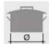
6.4 Cookwarediameters
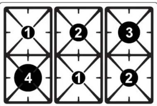
text_image
1 2 3 4 1 2| Burner∅min.(cm)∅max.(cm) | |||
| 1 | Auxiliary12 | 14 | |
| 2 | Semi-rapid | 16 | 24 |
| 3 | Rapid | 18 | 26 |
| 4 | Wok | 18 | 26 |
Topreventdamagetotheapplianceoradjacentunits,allpansorgriddlesmustbeplacedinsidethe perimeterofthehob.
7.USINGTHEOVEN
7.1 Before using the appliance

- Removeanylabels(apartfromthetechnicaldataplate)fromtrays,drippingpansandthecooking compartment.
- Removeanyprotectivefilmfromtheoutsideorinsideoftheappliance,includingfromaccessories suchastrays,drippingpans,thepizzaplateorthebasecover.
- Before using the appliance for the first time, remove all accessories from the oven compartment and wash them as indicated in "9.CLEANING AND MAINTENANCE".

Heattheemptyappliancetothemaximumtemperatureinordertoremoveanymanufacturing residueswhichcouldaffectthefoodwithunpleasantodours.
7.2Ovenrunners
Theovenfeatures4runnersforpositioningtraysandracksatdifferent heights. Theinsertionheightsareindicatedfromthebottomupwards (seefigure).
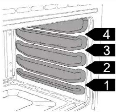
text_image
1 2 3 47.3 Storage compartment(onsomemodelsonly)
The storage compartment is in the bottom of the cooker. It provides storages space for the appliance's metal accessories and must not be used to store flammable materials, cloths, paper etc.
natural_image
Exterior view of a modern air conditioner unit (no text or symbols visible)
Donotopenthestoragecompartmentwhentheovenisonandstillhot. Thetemperaturesinsideitmay beveryhigh.
7.4Coolingsystem
The appliance is equipped with a cooling system which comes into operation as soon as a cooking function starts, with the exception of the gas burner where start-up is delayed. The can cause steady outflow of air that exits from the rear of the appliance and which may continue for a brief period of time even after the appliance has been turned off.
7.5Internallight
Thelightinsidetheovencomesonwhenanyfunctionisselected,exceptwhenthebottomburneris
beingused, in which casethetimerknobmust be turned to symbol

7.6 General warnings and advice for use
 | Allcookingoperationsmustbecarriedoutwiththedoorclosed.Thedissipationofheatmay causehazards. | |
 | Duringcooking,donotcoverthebottomoftheovenwithaluminiumortinfoilanddonotplacepansor oventraysonitasthismaydamagetheenamelcoating.Ifyouwishtousegreaseproofpaper,placeitso thatitwillnotinterferewiththehotaircirculationinsidetheoven. | |
 | Forthebestcookingresults,werecommendplacingcookwareinthe centreoftherack. | 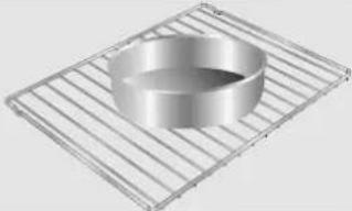 |
 | Topreventanysteamintheovenfromcausingproblems,openthe doorintwostages:keepithalfopen(5cmapprox.)for4-5seconds andthenfullyopen.Toaccessfood,alwaysleavethedoropenas shortatimeaspossibletopreventthetemperatureintheovenfrom fallingandruiningthefood. | 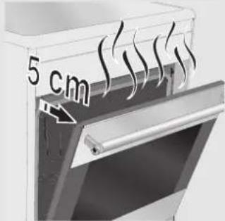 |
| Topreventexcessiveamountsofcondensationfromformingontheinternalglass,hotfoodshouldnotbe leftinsidetheovenfortoolongaftercooking. | ||
 | Whilecookingdessertsorvegetables,excessivecondensationmayformontheglass.Inorderto avoidthis,openthedorverycarefullyacoupleoftimeswhilecooking. | |
 | Topreventhazardousoverheating,theappliance'slid(wherepresent)mustalwaysberaisedwhenusing theoven. | |
 | Heattheemptyappliancetothemaximumtemperatureinordertoremoveanymanufacturing residueswhichcouldaffectthefoodwithunpleasantodours. | |
7.7 Electronicprogrammer(onsomemodelsonly)
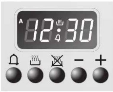
text_image
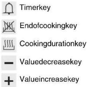
A 82:30LISTOFFUNCTIONS
text_image
Timerkey Endofcookingkey Cookingdurationkey - Valuedecreasekey + Valueincreasekey7.7.1 Settingthetime
Onthefirstuse,orafterapowerfailure,willbeflashingontheappliance'sdisplay.Pressthe
andkeystogether, andatthesametimepressthevalueadjustmentkey sor: this will increase or decrease the setting by on minute to foreach pressure. Presseitherofthevaluemodificationkeystodisplay the current time. Before each programmers setting, activatetherequired function and temperature.
7.7.2 Semi-automatic cooking
Semi-automaticcookingisthefunctionwhichallowsacookingoperationtobestartedandthenended afteraspecificlengthoftimesetbytheuser.
Pressthekeyandthedisplaywilllightupshowingthefigures;keepitpressed, andatthe same timeusethekeysortosetthecdekingduration.
When is released, the count of the programmed cooking duration will start and the display will show the current time together with 1 , and A (to indicate that a programmed cooking operation has been set).
7.7.3 Automatic cooking
This functions switch the ovenon and off entirely automatically.
Pressthekeyandthedisplaywilllightupshowingthefigures;keepitpressed;andatthe sametimeusethevaluemodificationkeysortosetthecockingduration.
Pressthekeyandthedisplaywillshowthesumofthecurrenttimeplusthecookingduration:keep
it pressed, and at the same time use the value modification keys — or + to adjust the end of cooking time.
When 📄 is released, the programmed count will start and the display will show the current time togetherwiththesymbolsAand.
After making the setting, press the , , , key to view the remaining cooking time; press the , , , key to view the cooking end time. The logic prevents the setting of incompatible values (e.g. the programmer will not accept a cooking end time with a duration which is too long for its value).
7.7.4Endofcooking
Attheendofcookingtheovenwillswitchoffautomaticallyandsimultaneouslyabuzzerwillstartto sound intermittently. After the buzzer has been deactivated, the display will return to show the current timetogetherwiththesymboltoindicatethattheovenhasreturnedtomanualusemode.
7.7.5Timer
Theprogrammercanalsobeusedasanordinarytimer.
Pressthekeyandthedisplaywillshowthefigures;keeppressedandsimultaneously
pressthevaluemodificationkey sor. Whenthe key is released the count will start and the
displaywillshowthecurrenttimeandthesymbol.

Afterthesetting,todisplaythetimeleftpressthekey.

Intimermode, theovenoperation will not be cut out at the end of these time.
7.7.6Adjustingthebuzzervolume
The buzzervolumecanbevaried(3settings)whileitisinoperationbypassing.

7.7.7 Stoppingthebuzzer
The buzzer stops automatically after about seven minutes. It can be deactivated manually by pressing keys — and together.
Toswitchofftheappliance, returnallknobstothe0setting.
7.7.8 Deletingthesetdata
Having programmed a semi-automatic or automatic cooking operation, this programming can be cancelled by holding down the key for the function which has just been programmed and simultaneously pressing keysor until + appears on the display.
The programmer will interpret the cancellation of the program as terminating the cooking operation.
7.7.9 Modifyingthesetdata
Thesetcookingdatacanbemodifiedatanytimebyholdingdownthefunctionkeyandatthesametime pressingthekeysortechangthevalue.
8.COOKINGWITHTHEOVEN

STATIC:
Astheheatcomesfromaboveandbelowatthesametime, thissystemisparticularlysuitableforcertain typesoffood. Traditionalcooking, alsoknownasstaticorthermalradiationcooking, issuitablefor cookingjustonedishatatime. Perfectforalltypesofroasts, breadandcakesandinanycase particularlysuitableforfattymeatssuchasgooseandduck.

BOTTOM:
Theheatcomingjustfromthebottomallowsyoutocompletethecookingoffoodsthatrequireahigher bottomtemperature,withoutaffectingtheirbrowning.Parfectforcakes,pies,tartsandpizzas.

SMALLGRILL(onsomemodelsonly):
Usingonlytheheatreleasedfromthecentralelement,thisfunctionallowsyoutogrillsmallportionsof meatandfishformakingkebabs,toastedsandwichesandanytypesofgrilledvegetablesidedishes.

LARGEGRILL:
Theheatcomingfromthegrillelementgivesperfectgrillingresultsaboveallforthinandmedium thicknessmeatandincombinationwiththerotisserie(wherepresent)givesthefoodanevenbrowning attheendofcooking. Perfectforsausages, ribsandbacon. Thisfunctionenableslargequantities of food, particularlymeat,tobegrilledevenly.

ROTISSERIEGRILL(onsomemodelsonly):
Therotisserieworksincombinationwiththegrillelement,allowingtoperfectlybrownfood.

FAN-ASSISTEDGRILL:
The air produced by the fans often strengthen the strongest heat wave generated by the grill, grilling perfectly even very thick foods. Perfect for large cut so meat (e.g. shin of pork).

TURBO:
The combination off an-assisted cooking and traditional cooking allow st o cook different food on several level extremely quickly and efficiently, without odours and flavours mingling. Perfect for large volumes that call for intense cooking. (Form multiple-level cooking, were recommend using the 2 nd and 4 th runners.)

CIRCULAR:
The combination of the fan and the circular element (incorporated in therearoftheoven) allows you to cook different food on several levels, as long as they need the same temperature and smart type of cooking. Hot air circulation ensures instant and uniform distribution of heat. It will be possible, for instance, to cook fish, vegetables and biscuits simultaneously (ondifferent levels) without mixing odours and flavours.
(Formultiple-levelcooking, werecommendusingthe2 ^nd and4 ^th runners.)

DEFROSTING:
Rapiddefrostingishelpedbyswitchingonthefanprovidedandthetopheatingelementthatensure uniformdistributionoflowtemperatureairinsidetheoven.
8.1 Cooking advice and instructions
8.1.1 General advice
- We recommend preheating the oven before putting food in. Place the food in the oven only once the cookinglightisoff.
- Forcookingonseverallevels, were recommend using a fan-assisted function to achieve uniform cooking at all heights.
- Ingeneral, it is not possible to shorten cooking times by increasing the temperature (the food could be overcooked on the outside and undercooked on the inside).
- Whilecookingdessertsorvegetables,excessivecondensationmayformontheglass.Inorderto avoidthis,openthedorverycarefullyacoupleoftimeswhilecooking.
- Forrapidpreheatinguseafan-assistedfunction, thenselecttherequiredfunction.
8.1.2 Advice for cooking meat
- Cooking times, especially for meat, vary according to the thickness and quality of the food and to consumertaste.
- Were recommend using a weatherometer for meat when roasting it. Alternatively, simply press on the roast with aspoon: if it is ready; if not, it needs another few minutes cooking.
8.1.3 Advice for cooking desserts and biscuits
•Usedarkmetalmouldsfordesserts:theyhelptoabsorbtheheatbetter.
- Thetemperatureandthecookingtimedependonthequalityandconsistencyofthedough.
- To check whether the dessert is cooked right through: at the end of the cooking time, put a toothpick into the highest point of the dessert. If the dough does not stick to the toothpick, the dessert is cooked.
- If the dessert collapses when it comes out of the oven, on the next occasion reduce the set temperature by about 10^ C, selecting longer cooking time if necessary.
8.1.4 Advice for defrosting and proving
- Were recommend positioning frozen foods sinalid less container on the first shelf of the oven.
•Thefoodmustbedefrostedwithoutitswrapping.
- Layoutthefoodstuffstobedefrostedevenly, notoverlapping.
- When defrosting meat, we recommend using a rack positioned on the second runner with the food on it and a tray positioned on the first runner. In this way, the liquid from the defrosting food drains awayfromthefood.
- Themostdelicatepartscanbecoveredwithaluminiumfoil.
- Forsuccessfulproving, a container of waters should be placed in the bottom of the oven.
8.1.5 Advice for cooking with the Grill and the Fan-assisted grill
- Using the Grill function ⚡, meat can be grilled even when it is put into the cold oven; preheating is recommended if you wish to change the effect of the cooking.
- With the Fan-assisted grill function 🎨, however, we recommend that you preheat the oven before grilling.
8.2 Cooking information table
| FoodWeightFunction | Runner position fromthe | Temperature °C | Time (minutes) | |||
| FIRSTCOURSES | ||||||
| Lasagne3KgStatic2or3220-23040-50 | ||||||
| Oven-bakedpastaStatic2or3220-23040 | ||||||
| MEAT | ||||||
| Roast veal | 1 Kg | Circular | 3 | 180 - 190 | 70 - 80 | |
| Porkloin1KgCircular | 3 180-19070-80 | |||||
| Pork shoulder | 1 Kg | Turbo | 3 | 180 - 190 | 90 - 100 | |
| Roast rabbit | 1 Kg | Circular | 3 | 180 - 190 | 70 - 80 | |
| Turkey breast | 1 Kg | Turbo | 3 | 180 - 190 | 110 - 120 | |
| Roast pork neck | 1 Kg | Turbo | 3 | 180 - 190 | 190 - 210 | |
| Roast chicken | 1 Kg | Turbo | 3 | 190 - 200 | 60 - 70 | |
| GRILLEDMEATS | 1^st side | 2^nd side | ||||
| Pork chops | Fan-assisted grill | 5 | 250 | 7 - 9 | 5 - 7 | |
| Pork fillet | Grill | 4 | 250 | 9 - 11 | 5 - 9 | |
| Beef fillet | Grill | 4 | 250 | 9 - 11 | 9 - 11 | |
| Liver slices | Small grill | 5 | 250 | 2 - 3 | 2 - 3 | |
| Sausages | Fan-assisted grill | 4 | 250 | 7-9 | 5 - 6 | |
| Meatballs | Grill | 4250 | 7-95-6 | |||
| ROTISSERIEMEAT(wherepresent) | ||||||
| Chicken | Rotisseriegrill | On a | 250 | 60-70 | ||
| FISH | ||||||
| Salmon trout | 0.7 Kg | Circular | 3 | 160 - 170 | 35-40 | |
| BREADandFOCACCIA | ||||||
| Pizza | Turbo | 1 | 250 | 6 - 10 | ||
| Bread | Circular | 2 | 190-20025-30 | |||
| Focaccia | Turbo | 2 | 180 - 190 | 15 - 20 | ||
| DESSERTS | ||||||
| Ringcake | Circular | 3160 | 55-60 | |||
| Fruit tart | Circular | 3 | 160 | 30 - 35 | ||
| Fruit tart | Static | 3 | 170 | 35 - 40 | ||
| Short pastry | Circular | 2 or 3 | 160 - 170 | 20 - 25 | ||
| Jam tarts | Turbo | 2 or 3 | 160 - 170 | 40 - 50 | ||
| Paradiseecake | Static2or3170 | 40-50 | ||||
| Paradiseecake | Circular | 3160 | 50-60 | |||
| Cream puffs | Turbo | 3 | 150 - 160 | 40 - 50 | ||
| LightspongecakeCircular | 3 150-16040-50 | |||||
| Rice pudding | Turbo | 3 | 160 | 40 - 50 | ||
| Ricepudding | Static | 3170 | 50-60 | |||
| Brioche | Circular | 3160 | 25-30 | |||
| Brioche (on multiple runners) | Circular - Turbo | 2 - 4 | 160 - 170 | 30 - 35 | ||
| Short pastry biscuits (on multiple | Circular - Turbo | 2 - 4 | 160 - 170 | 16 - 20 | ||

The times indicated in the following tables do not include the preheating times and are provided asaguideonly.
9.CLEANINGANDMAINTENANCE

Donotusesteamjetsforcleaningtheappliance. The steam could reach the electronics, damaging them and causing short-circuits.
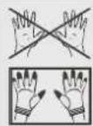
WARNING: Foryoursafety, you are advised to wear protective gloves while performing any cleaningorextraordinary maintenance.

Donotusecleaningproductscontainingchlorine,ammoniaorbleachonsteelpartsorpartswith metallicfinishesonthesurface(e.g.anodizing,nickel-orchromium-plating).
Werecommendtheuseofcleaningproductsdistributedbythemanufacturer.
9.1 Cleaningstainlesssteel
Tokeepstainlesssteelingoodconditionitshouldbecleanedregularlyafteruse.Letitcoolfirst.
9.2 Ordinarydailycleaning
Tocleanandpreservestainlesssteelsurfaces,alwaysuseonlyspecificproductsthatdonotcontain abrasivesorchlorine-basedacids.
How to use: pour the product onto a damp cloth and wipe the surface, rinse thoroughly and dry with a softclothoramicrofibrecloth.
9.3Foodstainsorresidues
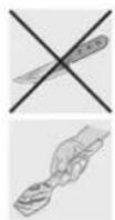
Donotusemetallicspongesorsharpscrapersastheywilldamagethesurfaces.
Use ordinary non-abrasive products with the aid of wooden or plastic utensils if necessary. Rinse thoroughly and dry with asoft cloth or amicrofibre cloth.
Donotallowresiduesofsugaryfoods(suchasjam)tosetinsidetheoven. If left to set fortoolong, they might damage the enamellining of the oven.
9.4Cleaningthe Teppanyakiplate(onsomemodelsonly)
The Teppanyaki plate is easier to clean when it is still lukewarm. Use conventional specific detergents for stainlesssteelandnon-abrasivesponges.Anyremainingencrustationsorfoodresiduescanbeeasily removedbysoakingtheplateforawhile.Forverystubbornencrustations,werecommendusingthesuppliedscraper.Dryitcarefully.

Donotsoaktheplateinwaterimmediatelyafteruse.
Waitforittocooldown.
9.5Cleaningthedoorglazing
The glass in the door should always be kept through a clean. Use absorbent kitchen roll; remove stubborn dirt with adamps sponge and an ordinary detergent.
Do not use abrasive or corrosive detergents to clean the oven's door glass panels (e.g. powder products, spot-removersandwiresponges). Donotuseroughorabrasivematerialsorsharpmetalscrapersto clean the oven's glass doors since they may scratch the surface.
9.6Cleaningthedoorseal
Tokeepthesealclean,useanon-abrasivespongeandlukewarmwater.Thesealshouldbesoftand flexible (with the exception of pyrolitic models). In pyrolitic models, the seal may flatten over time and lose its original shape. To restore it, pinch the seal all the way along. This also helps remove any dirt on the seal.
9.7 Cleaning the cooking hobparts
9.7.1 Panstands
Removethepanstandsandcleanthemwithlukewarmwaterandnon-abrasivedetergent,makingsure toremoveanyencrustations.Drythemthoroughlyandreturnthemtothehob. Continuouscontactbetweenhepanstandsandtheflamecancausemodificationstotheenamelover timeinthosepartsexposedtoheat.Thisisacompletelynaturalphenomenonwhichhasnoeffectonthe operationofthiscomponent.
Donowashthesepartsinadishwasher.
9.7.2 Burnercapsandflame-spreadercrowns
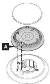
Theburnercapsandflame-spreadercrownscanberemovedforeasiercleaning. Washtheminwarmwaterandnon-abrasivedetergentmakingsuretoremoveany encrustation,thenwaituntiltheyareperfectlydry. Refittheflame-spreadercrowns,makingsurethattheyarecorrectlyinplacewith theirrespectiveburnercaps,andensuringthattheholesAintheflame-spreaders arealignedwiththeignitersandthermocouples.
text_image
A
Donowashthesepartsinadishwasher.
9.7.3 Ignitersandthermocouples
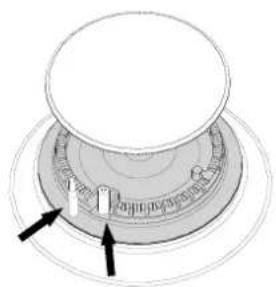
Forcorrectoperation, the igniters and thermocouples must always be perfectly clean. Check them frequently and clean them with adamp cloth if necessary. Remove any dry residues with a woodentooth pick or an needle.
natural_image
Diagram of a circular mechanical component with two arrows pointing to features (no text or symbols)
Donotusecleaningproductscontainingchlorine,ammoniaorbleachonsteel partsorpartswithmetallicfinishesonthesurface(e.g.anodizing,nickel-or chromium-plating).
9.8Cleaningtheoven
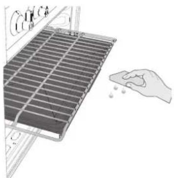
- Clean the oven racks with warm water and non-abrasive detergent.Rinseanddry.
- For easier cleaning, the door can be removed (see "10.1 Removingthedoor").
natural_image
Illustration of a hand cleaning a solar panel with a cloth (no text or symbols)
The oven should be operated at the maximum heat setting for 15/20 minutes after use of specific products, to burn off the residues left inside the oven.

Whentheoperationiscomplete,damppartsshouldbedriedthoroughly.
10. EXTRAORDINARYMAINTENANCE
Theovenrequiresperiodicminormaintenanceorreplacementofpartssubjecttowear,suchasgaskets, lightbulbs,etc.Specificinstructionsforeachoperationofthiskindaregivenbelow.

Before any intervention that requires access to live parts, disconnect the appliance from the powersupply.
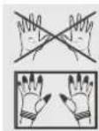
WARNING: Foryoursafety, you are advised to wear protective gloves while performing any cleaningorextraordinary maintenance.
10.1 Removingthedoor
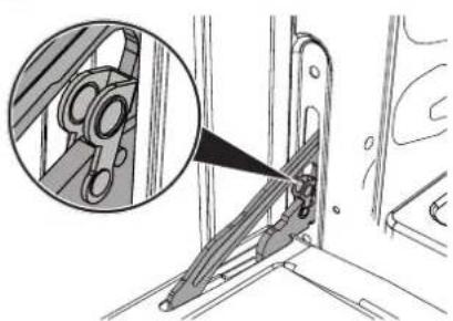
natural_image
Technical illustration of a mechanical assembly with an inset showing a close-up of a component (no text or symbols present)- Openthedorfullyandlift leversnearthetwohinges.
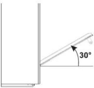
text_image
30°- Graspthedooronboth sideswithbothhands, lift it forming an angle of around 30^ and remove it.
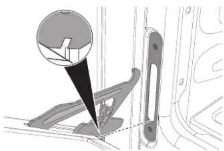
natural_image
Mechanical assembly diagram showing a bracket with a magnified inset of a component (no text or symbols)- To reassemble the door, put the hingesintotherelevantslotsinthe oven, making sure that grooved sectionsarerestingcompletelyinthe slots. Lowerthedooranddisengage thelocklevers.
10.2Replacingthelightbulb
Ifalightbulbneedstobereplacedbecauseitiswornorburntout, unscrewthebulbcover.Removethebulbbyunscrewingitand thenreplaceitwithasimilarbulb(25W).
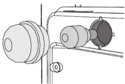
natural_image
Technical line drawing of a mechanical assembly with two circular components and a shaft (no text or symbols)10.3Removingthedoorseal
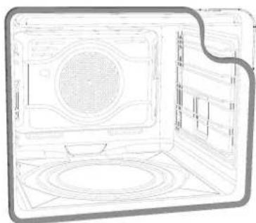
To permit thorough cleaning of the oven, the door seal may be removed.
Therearefastenersonallfoursidestoattachittotheedgeofthe oven.Pulltheedgesofthesealoutwardstodetachthefasteners.The sealmustbereplacedwhenitloseselasticityandhardens.
natural_image
Line drawing of a laptop with a circular vent and grid layout (no text or symbols)11.INSTALLATION

The appliance connection point shall be accessible with the appliance installed.
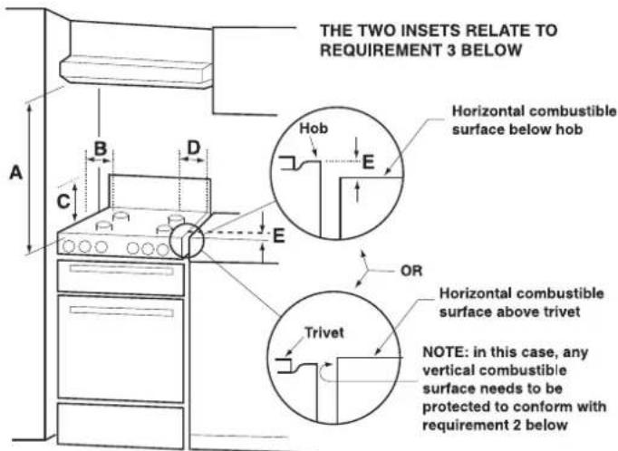
11.1 Clearances above and around domestic appliances
ExtractfromAS5601
text_image
THE TWO INSETS RELATE TO REQUIREMENT 3 BELOW Horizontal combustible surface below hob Hob E OR Horizontal combustible surface above trivet Trivet NOTE: in this case, any vertical combustible surface needs to be protected to conform with requirement 2 belowREQUIREMENTS
1Overheadclearances-(MeasurementA)Rangehoodsandexhaustfansshallbeinstalledin accordancewiththemanufacturer'sinstructions.However,innocaseshalltheclearancebetween thehighestpartofthehobofthecookingapplianceandarangehoodbelessthan600mmor,foran overheadexhaustfan,750mm.Anyotherdownwardfacingcombustiblesurfacelessthan600mm abovethehighestpartofthehobshallbeprotectedforthefullwidthanddepthofthecookingsurface areainaccordancewithClause5.12.1.2.However,innocaseshallthisclearancetoanysurfacebe lessthan450mm.
2 Side clearances – (Measurements B & C) Where B, measured from the periphery of the nearest burnertoanyverticalcombustiblesurface,islessthan200mm,thesurfaceshallbeprotectedin accordancewithClause5.12.1.2toaheightCofnotlessthan150mmabovethehobforthefull dimension(widthordepth)ofthecookingsurfacearea.Wherethecookingapplianceisfittedwitha 'splashback',protectionoftherearwallisnotrequired.
3AdditionalrequirementsforFreestandingandElevatedCookingAppliances-(Measurements
D & E) Where D, the distance from the periphery of the nearest burner to a horizontal combustible surface is less than 200mm, then E shall be 10mm more, or the horizontalsurfaces shall be above the trivet. See insets above.
NOTES
1 Requirement3 does not apply to a freestanding or elevated cooking appliance which is designed to prevent flames or the cooking vessels from extending beyond the periphery of the appliance.
2 The 'cooking surface area' is defined as that part of the appliance where cooking normally takes place and does not include those part so the appliance containing control knobs.
3Fordefinitionofhob,seeClause1.4.64.
4Fordefinitionoftrivet,seeClause1.4.109.
5Considerationistobegiventowindowtreatmentswhenlocatednearcookingappliances.See Clause5.3.4.
11.2 Combustiongasdischarge

Combustiongasesmaybedischargedbymeansofhoodsconnectedtoafluewithreliablenatural draught, or a fan extraction system. An effective extraction system requires careful design by an authorisedspecialist,andmustcomplywiththeregulationdistancesandpositions.Afterinstallation,the engineermustissueacertificateofcompliance.
11.3Gasconnection
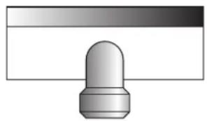
This appliance is suitable for installation with Natural Gas or ULPG (propane/butane). Referto "12.3 Burner and nozzle characteristic stable" for therelevant burner pressure and appropriate injectorsizes. When the appliance is to be connected to Natural Gasthenthe pressureregulator supplied must be fitted to the gas inlet. A test point (for checking the gas pressure) is supplied either with the regulator or as a separate fitting in the case of ULPG (propane) appliances.
Connectionoftheappliancetothegassupplymustbeinaccordance withtherequirementsofAS5601.A½"BSPconnectorattheinletis recommendedandthegassupplylinetotheappliancemustbeof adequatelylengthtoallowsufficientwithdrawalofapplianceforserviceor disconnectionandbe:
- annealedcopperpipeor;
2.flexiblehoseaccordingtoAS/NZ1869&beatleastClass"B",10mm diameter.
The appliance must be installed with provision to allow the gastobeturned off and disconnected for servicing and removal of the appliance as required from the gassupply. Before the appliance is operated make certain all relevant parts are placed in the correct position.
Oncompletionoftheinstallation,theinstallerMUSTcheckforgasleaksandtesteachburner individuallyforthecorrectflame.Onceallburnershavebeentestedindividually,turnallburnerson together.Warrantyservicecallsdonotcovertheseadjustments!
To check the operating pressure of the appliance it is recommended at least 2 large size burners are used. Ensure appliance is secured to all when installation is completed.
N.G. The regulator supplied must be fitted to the 12 BSP thread at the rear of the appliance. An approved manual shut-off valve must be installed. The N.G. regulator must be checked and adjusted to 1.0kPa after installation.
U.L.P.G.Canbeconnectedtotheinletfittingdirectly.Thepressuremust becheckedtoensureitisoperatingat2.75kPa.Aseparatetestpoint fittingmustbeinstalledbetweenhepiping&theapplianceforthe pressuretobecheckedtoensureitisoperatingat2.75kPa.
natural_image
Simple 3D diagram of a button-like object with a rounded top, placed on a rectangular base (no text or symbols)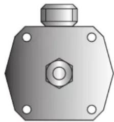
natural_image
3D rendering of a hexagonal mechanical component with a central bolt and mounting holes (no text or symbols)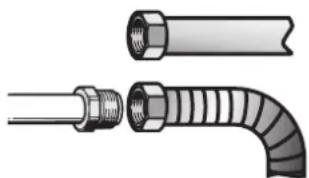
natural_image
Illustration of two pipe fittings with different end caps and threaded ends, no text or symbols present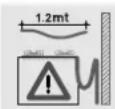
Installation with flexible hose must be carried out so that the length of the piping does not exceed 1,2 metres when fully extended; make sure that the hoses do not come into contact with moving parts and that they are not crushed in any way.
11.3.1 Connectiontoliquidgas

Use a pressure regulator and make the connection on the gas cylinder following the guidelines set out in theregulationsinforce.
Make sure that the supply pressure complies with the values indicated in the paragraph “10.3 Burner andnozzlecharacteristicstables”.
11.4 Roomventilation

Theroomcontainingtheapplianceshouldhaveapermanentairsupplyinaccordancewiththe standards in force. The room where the appliance is installed must have enough air flow needed for the regular combustion of gas and the necessary air change in the room itself. The hob shall be installed in roomswithnaturalventilation,asrequiredbyStandardsregulationsAS/NZS5601.
11.5 Extraction of the combustion products

The combustionproductsmaybeextractedbymeansofhoodsconnectedtoanaturaldraughtchimney whose efficiency is certain or via forced extraction. An efficient extraction system requires precision planningbyaspecialistqualifiedinthisareaandmustcomplywiththepositionsanddistancesindicated bytheregulations.Whenthejobiscomplete,theinstallermustissueacertificateofconformity.
11.6 Electrical connection

Makesurethevoltageandthecross-sectionofthepowersupplylinematchthespecificationsindicated ontheidentificationplatepositionedontheappliance.Donotremovethisplateforanyreason.Acopy of theplateisattachedtotheinstructions.

The appliancemustbeconnectedtothepowersupplybyaqualifiedtechnician.

Beforeperforminganyoperations,switchoffthepowersupplytotheappliance.

The appliance must be connected to earth in compliance with the electrical systems safety regulations.

Wheretheapplianceisconnectedtothepowergridviaaplugandsocket,bothofthesemustbeofthe sametypeandconnectedtothepowercableinaccordancewiththeapplicableregulations. Thesocket mustbeaccessibleaftertheappliancehasbeenbuiltin.
NEVERUNPLUGBYPULLINGONTHECABLE.

Shouldtheearthingwireneedreplacingitmustbelongerthanthecurrentconductionwiressothat,if theplugistornoffthepowercable,itisthelasttobedetached.
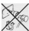
Avoiduseofadaptersandshuntsasthesecouldcauseoverheatingandriskofburns.

If a fixed connection is being used, fit the power line with an omnipolar circuit breaker with a contact opening gap equal to or greater than 3 mm, in an easily accessible position close to the appliance.

Themanufacturerdeclinesallresponsibilityfordamagetopersonsorthingscausedbynon-observanceoftheaboveprescriptionsorbyinterferencewithanypartoftheappliance.
| APPLIANCE TYPE (CM) | POSSIBLECONNECTION TYPES | CABLETYPE(ifnotpresent) | |
| 50 | 380 - 415 V 3N~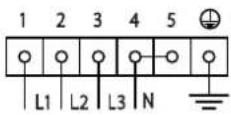 | 5-pole 5 × 1.5 mm^2 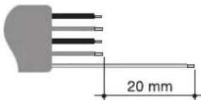 | H05V2V2-F |
380 - 415 V 2N~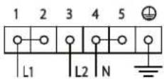 | 4-pole 4 × 1.5 mm^2 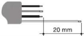 | H05V2V2-F | |
220 - 240 V 1N~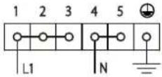 | 3-pole 3 × 2.5 mm^2 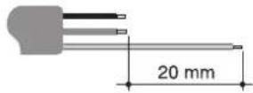 | H05V2V2-F | |
- UseH05V2V2-Fcablesresistanttoatleast90°C.
•Thevaluesindicatedaboverefertothecross-sectionoftheinternalconductor. - Thetighteningtorqueofthescrewsoftheterminalsupplywiresmustbe1.5-2Nm.
•The aforementioned powercables are sized taking into account the coincidence factor (in compliance with standard EN60335-2-6).
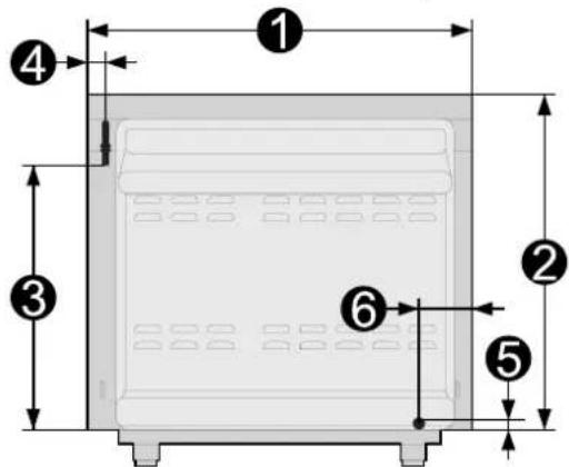
Overall dimensions: location of gas and electrical connection points (all measures in mm).
text_image
① ② ③ ④ ⑤ ⑥1898
2783
3618
440
512
6124
11.7 Positioningtheskirt(onsomemodelsonly)
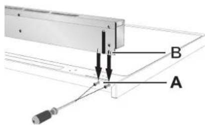
Theskirtmustalwaysbepositionedandsecuredcorrectlyonthe appliance.
1 Loosenthe4screws(A)onthebackoftheworktop(2foreach side).
2Placetheskirtabovetheworktop, takingcaretoaligntheskirt's slots(B)withthescrews(A).
3Securetheskirttotheworktopbytighteningscrews(A).
text_image
A B A11.8 Positioning and levelling the appliance
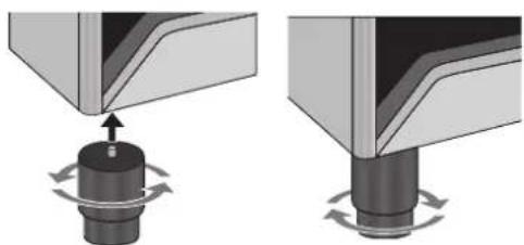
Aftermakingtheelectricaland/orgasconnections,levelthe applianceonthefloorbymeansofitsfouradjustablefeet.
Firstinsertthefrontfeetandthentherearfeet.
The appliance must be properly levelled to ensure better stability. Screwor unscrew the bottom part of the foot until the appliance is stable and level on the floor.
natural_image
Mechanical assembly diagram showing two stages of a mechanical press or valve mechanism with rotating components (no text or symbols)
Topreventpossibledamagetotheappliance, were recommendtoscrewfirstthefrontfeetandthenthe rearones.
11.9C91GMXATWallmountingbrackets
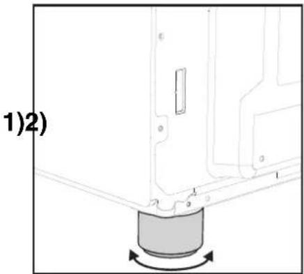
The fasteningsystem provided must be installed to ensure the appliance is stable. If installed correctly, this system prevents the appliance tipping over.
natural_image
Mechanical assembly diagram showing a component with a rotating base and labeled parts (no text or symbols beyond labels)1) Usetheadjustablefeettoleveltheapplianceat therequiredheight.
natural_image
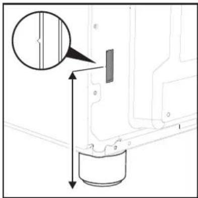
Technical diagram showing a mechanical component with dimension lines and an inset magnified view (no text or symbols)2) Measure the distance from the index of the opening to the floor.
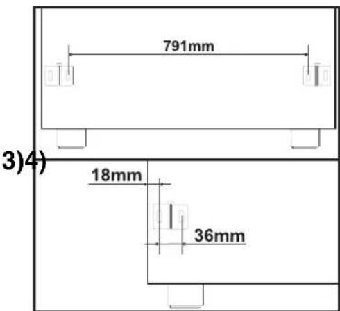
3)Usethesameheightonthewalltodrillthe holesforfasteningthebrackets. Thedistance between the centres of the holes is given in the diagram above.
natural_image
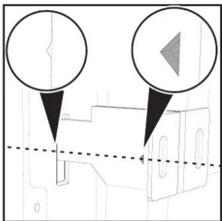
Pure technical diagram showing two circular components with arrows pointing to a central object, no text or symbols present.4) Before tightening the brackets fully to the wall, check that the index on the brackets is at the same height as the index on the back of the appliance. Position the appliance, taking care that the brackets are correctly inserted.
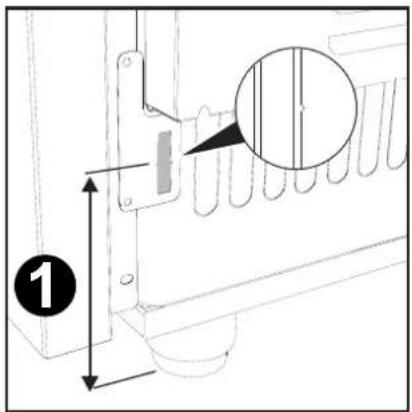
11.10C9GMXAWallmountingbrackets
The fasteningsystem provided must be installed to ensure the appliance is stable. If installed correctly, this system prevents the appliance tipping over.
1)
natural_image
Technical line drawing of a mechanical assembly with no visible text or symbols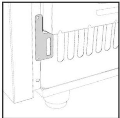
natural_image
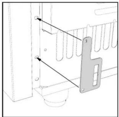
Technical line drawing of a door with a metal latch and vertical supports (no text or symbols)1) Secure the centering brackets for the wall brackets on both sides at the rear of the cooker as shown in the figure.
2)3
natural_image
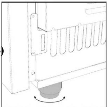
Technical line drawing of a mechanical component with a curved base and mounting bracket (no text or symbols)2) Usetheadjustablefeettoleveltheapplianceat therequiredheight.
text_image
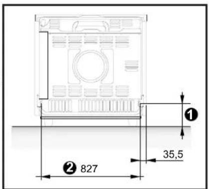
Technical diagram showing a mechanical assembly with labeled component '1' and an inset detail view highlighting a specific section.3) Measure the distance from the index of the opening to the floor.
4)
text_image
① 35,5 ② 8275)
natural_image
Technical line drawing of a mechanical component with two circular annotations and a dashed reference line (no text or symbols)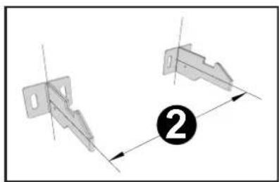
natural_image
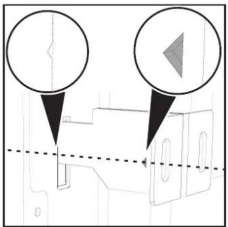
Technical diagram showing two mechanical bracket assemblies with dimension lines and a numbered label (2), no readable text or symbols present.4) Usethesameheightonthewalltodrillthe holesforfasteningthebrackets. Thedistance between the centres of the holes is given in the diagram above.
5) Before tightening the brackets fully to the wall, check that the index on the brackets is at the same height as the index on the back of the appliance. Position the appliance, taking care that the brackets are correctly inserted.
11.11 Wallfixing
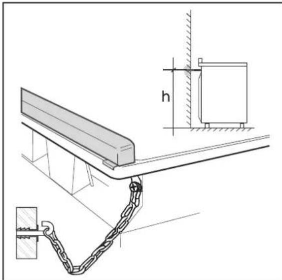
1Attachthechaintothecooker
2Stretchoutthechainattachedtothecookerhorizontallysothattheotherendtouchesthewall.
3Markthewallinthepositionwheretheholeistobedrilled.
4Drillthehole,insertawallplugandattachthechain.
5Oncethechainisinposition, pushthecookeragainstthewallandreducetheamountofchainlinks tokeepthechaintighttopreventanyexcessmovement.
natural_image
Technical line drawing of a mechanical assembly with chains and a wall, showing dimension h (no text or symbols)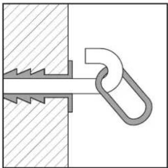
natural_image
Pure mechanical diagram showing a zigzag joint between two surfaces, no text or symbols presentBEFOREPERFORMINGANYOPERATIONS, SWITCHOFFTHEPOWERSUPPLYTOTHE APPLIANCE.
Appliance set for gas: Natural gas at a pressure of 1.0 kPa (see label on product)
In the case of operation with other types of gas, the burnnozzles must be changed and the minimum flame-adjusted on the gastaps.
Tochangethenozzles,proceedasdescribedinthefollowingparagraphs.
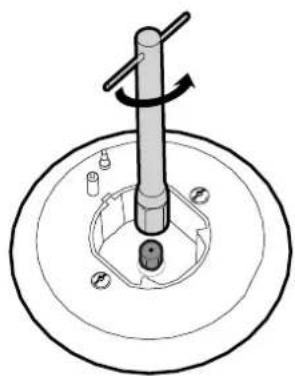
12.1 Replacing the hobnozzles
1 Removethepanstands, and remove all burnercaps and flame spreader crownstoaccesstheburnercasings.
2Unscrewthenozzlesusinga7mmsocketwrench.
3Replacetheburnernozzlesaccordingtothetypeofgastobeused(see
12.3Burnerandnozzlecharacteristicstable).
4Replacetheburnersinthecorrectposition.
natural_image
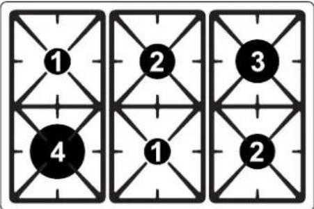
Mechanical assembly diagram showing a rotating shaft mounted on a circular base with mounting holes (no text or symbols)12.2 Arrangement of burners

text_image
① ② ③ ④ ① ②Bruciatore

Auxiliary

Semi-rapid

Rapid

Wok
12.3 Burner and nozzle characteristic stable
| BurnerULPG(PROPANE)-2.75KPa | |||
| Nominalgasconsumption (MJ/h) | Turn-downgas consumption(MJ/h) | Injector (mm) | |
| Auxiliary(1)3.91.50.54 | |||
| Semirapid(2)6.31.50.68 | |||
| Rapid(3)10.82.70.88 | |||
| Ultra-rapid(4)15.05.41.05 | |||
| Burner | NG(NATURALGAS)-1.0KPa | ||
| Nominalgasconsumption (MJ/h) | Turn-downgas consumption(MJ/h) | Injector (mm) | |
| Auxiliary(1)3.91.50.90 | |||
| Semirapid(2)7.51.51.20 | |||
| Rapid(3)12.02.71.55 | |||
| Ultra-rapid(4)15.85.41.85 | |||
12.4Finaloperations
Afterreplacingthenozzles, repositiontheflame-spreadercrowns, theburnercapsandthepanstands.
Following adjustment to a gas other than the one originally set in the factory, replace the gas setting label fixed to the appliance with the one corresponding to the new gas. The label is inserted inside the nozzlepack(wherepresent).
12.4.1 Adjusting the hobburnerminimumsettingforcityornaturalgas
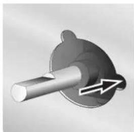
Light the burner and turn it to the minimum position. Extract the gas tap knob and turn the adjustment screw next to the tap rod (depending on the model) until the correctminimumflameisachieved. Refittheknoband verify that the burnerflameisstable(whenturningthe knob rapidly from the maximum to the minimum position the flame must not go out). Repeat the operation on all thegastaps.

natural_image
Mechanical component diagram showing a shaft and housing with an arrow indicating rotation (no text or symbols)