
KLX450R (2011) - Bicycle KAWASAKI - Free user manual and instructions
Find the device manual for free KLX450R (2011) KAWASAKI in PDF.


| Brand | Kawasaki |
| Model | KLX450R (2011) |
| Product Type | Off-road motorcycle |
| Engine Displacement | 449 cc |
| Engine Type | 4-stroke, single cylinder, DOHC |
| Cooling System | Liquid-cooled |
| Fuel System | Keihin FCR40 carburetor |
| Transmission | 5-speed, constant mesh, return shift |
| Final Drive | Chain drive |
| Front Suspension | 48 mm inverted fork, fully adjustable |
| Rear Suspension | Uni-Trak with piggyback reservoir, adjustable |
| Front Brakes | Single 250 mm disc, 2-piston caliper |
| Rear Brakes | Single 240 mm disc, 1-piston caliper |
| Seat Height | 940 mm (37.0 in) |
| Ground Clearance | 325 mm (12.8 in) |
| Fuel Capacity | 8.0 L (2.1 US gal) |
| Weight (curb) | 118 kg (260 lb) |
| Oil Capacity (with filter) | 1.1 L (1.16 US qt) |
| Spark Plug | NGK CR8E or equivalent |
| Battery | 12V, maintenance-free |
| Maintenance Interval | Oil change every 15 hours, valve check every 30 hours |
| Key Functions | Electric start, choke, engine stop switch |
Frequently Asked Questions - KLX450R (2011) KAWASAKI
User questions about KLX450R (2011) KAWASAKI
0 question about this device. Answer the ones you know or ask your own.
Ask a new question about this device
Download the instructions for your Bicycle in PDF format for free! Find your manual KLX450R (2011) - KAWASAKI and take your electronic device back in hand. On this page are published all the documents necessary for the use of your device. KLX450R (2011) by KAWASAKI.
USER MANUAL KLX450R (2011) KAWASAKI
Motorcycle Service Manual
Quick Reference Guide
| General Information 1 | |
| Periodic Maintenance 2 | |
| Fuel System 3 | |
| Cooling System 4 | |
| Engine Top End 5 | |
| Engine Right Side | 6 |
| Engine Lubrication System | 7 |
| Engine Removal/Installation | 8 |
| Crankshaft/Transmission | 9 |
| Wheels/Tires | 10 |
| Final Drive | 11 |
| Brakes | 12 |
| Suspension | 13 |
| Steering | 14 |
| Frame | 15 |
| Electrical System | 16 |
| Appendix | 17 |
This quick reference guide will assist you in locating a desired topic or procedure.
- Bend the pages back to match the black tab of the desired chapter number with the black tab on the edge at each table of contents page.
- Refer to the sectional table of contents for the exact pages to locate the specific topic required.
Motorcycle Service Manual
All rights reserved. No parts of this publication may be reproduced, stored in a retrieval system, or transmitted in any form or by any means, electronic mechanical photocopying, recording or otherwise, without the prior written permission of Quality Assurance Division/Consumer Products & Machinery Company/Kawasaki Heavy Industries, Ltd., Japan.
No liability can be accepted for any inaccuracies or omissions in this publication, although every possible care has been taken to make it as complete and accurate as possible.
The right is reserved to make changes at any time without prior notice and without incurring an obligation to make such changes to products manufactured previously. See your Motorcycle dealer for the latest information on product improvements incorporated after this publication.
All information contained in this publication is based on the latest product information available at the time of publication. Illustrations and photographs in this publication are intended for reference use only and may not depict actual model component parts.
LIST OF ABBREVIATIONS
| A ampere(s) lb pound(s) | |||
| ABDC | after bottom dead center | m | meter(s) |
| AC | alternating current | min | minute(s) |
| ATDC | after top dead center | N | newton(s) |
| BBDC | before bottom dead center | Pa | pascal(s) |
| BDC | bottom dead center | PS | horsepower |
| BTDC | before top dead center | psi | pound(s) per square inch |
| °C | degree(s) Celsius | r | revolution |
| DC | direct current | rpm | revolution(s) per minute |
| F | farad(s) | TDC | top dead center |
| °F | degree(s) Fahrenheit | TIR | total indicator reading |
| ft | foot, feet | V | volt(s) |
| g | gram(s) | W | watt(s) |
| h | hour(s) | Ω | ohm(s) |
| L | liter(s) | ||
COUNTRY AND AREA CODES
| AU | Australia | EUR | Europe |
| CA | Canada | US | United States |
| CAL | California |
EMISSION CONTROL INFORMATION
To protect the environment in which we all live, Kawasaki has incorporated crankcase emission (1) and exhaust emission (2) control systems in compliance with applicable regulations of the United States Environmental Protection Agency and California Air Resources Board. Additionally, Kawasaki has incorporated an evaporative emission control system (3) in compliance with applicable regulations of the United States Environmental Protection Agency.
1. Crankcase Emission Control System
This system eliminates the release of crankcase vapors into the atmosphere. Instead, the vapors are routed through an oil separator to the intake side of the engine. While the engine is operating, the vapors are drawn into the combustion chamber, where they are burned along with the fuel and air supplied by the fuel injection system.
2. Exhaust Emission Control System
This system reduces the amount of pollutants discharged into the atmosphere by the exhaust of this vehicle. The fuel, ignition and exhaust systems of this vehicle have been carefully designed and constructed to ensure an efficient engine with low exhaust pollutant levels.
3. Evaporative Emission Control System
The evaporative emission control system for this vehicle consists of low permeation fuel hoses and a fuel tank.
The Clean Air Act, which is the Federal law covering motor vehicle pollution, contains what is commonly referred to as the Act's "tampering provisions".
"Sec. 203(a) The following acts and the causing thereof are prohibited.
(3)(A) for any person to remove or render inoperative any device or element of design installed on or in a motor vehicle or motor vehicle engine in compliance with regulations under this title prior to its sale and delivery to the ultimate purchaser, or for any manufacturer or dealer knowingly to remove or render inoperative any such device or element of design after such sale and delivery to the ultimate purchaser.
(3)(B) for any person engaged in the business of repairing, servicing, selling, leasing, or trading motor vehicles or motor vehicle engines, or who operates a fleet of motor vehicles knowingly to remove or render inoperative any device or element of design installed on or in a motor vehicle or motor vehicle engine in compliance with regulations under this title following its sale and delivery to the ultimate purchaser...”
NOTE
○ The phrase “remove or render inoperative any device or element of design” has been generally interpreted as follows.
- Tampering does not include the temporary removal or rendering inoperative of devices or elements of design in order to perform maintenance.
- Tampering could include.
a. Maladjustment of vehicle components such that the emission standards are exceeded.
b. Use of replacement parts or accessories which adversely affect the performance or durability of the motorcycle.
c.Addition of components or accessories that result in the vehicle exceeding the standards.
d. Permanently removing, disconnecting, or rendering inoperative any component or element of design of the emission control systems.
WE RECOMMEND THAT ALL DEALERS OBSERVE THESE PROVISIONS OF FEDERAL LAW, THE VIOLATION OF WHICH IS PUNISHABLE BY CIVIL PENALTIES NOT EXCEEDING \$10 000 PER VIOLATION.
TAMPERING WITH NOISE CONTROL SYSTEM PROHIBITED
Federal law prohibits the following acts or the causing thereof. (1) The removal or rendering inoperative by any person other than for purposes of maintenance, repair, or replacement, of any device or element of design incorporated into any new vehicle for the purpose of noise control prior to its sale or delivery to the ultimate purchaser or while it is in use, or (2) the use of the vehicle after such device or element of design has been removed or rendered inoperative by any person.
Among those acts presumed to constitute tampering are the acts listed below.
- Replacement of the original exhaust system or muffler with a component not in compliance with Federal regulations.
- Removal of the muffler or any internal portion of the muffler.
- Removal of the air box or air box cover.
- Modifications to the muffler or air intake system by cutting, drilling, or other means if such modifications result in increased noise levels.
Foreword
This manual is designed primarily for use by trained mechanics in a properly equipped shop. However, it contains enough detail and basic information to make it useful to the owner who desires to perform his own basic maintenance and repair work. A basic knowledge of mechanics, the proper use of tools, and workshop procedures must be understood in order to carry out maintenance and repair satisfactorily. Whenever the owner has insufficient experience or doubts his ability to do the work, all adjustments, maintenance, and repair should be carried out only by qualified mechanics.
In order to perform the work efficiently and to avoid costly mistakes, read the text, thoroughly familiarize yourself with the procedures before starting work, and then do the work carefully in a clean area. Whenever special tools or equipment are specified, do not use makeshift tools or equipment. Precision measurements can only be made if the proper instruments are used, and the use of substitute tools may adversely affect safe operation.
For the duration of the warranty period, we recommend that all repairs and scheduled maintenance be performed in accordance with this service manual. Any owner maintenance or repair procedure not performed in accordance with this manual may void the warranty.
To get the longest life out of your vehicle:
- Follow the Periodic Maintenance Chart in the Service Manual.
- Be alert for problems and non-scheduled maintenance.
- Use proper tools and genuine Kawasaki Motorcycle parts. Special tools, gauges, and testers that are necessary when servicing Kawasaki motorcycles are introduced by the Service Manual. Genuine parts provided as spare parts are listed in the Parts Catalog.
- Follow the p procedures in this manual carefully. Don't take shortcuts.
- Remember to keep complete records of maintenance and repair with dates and any new parts installed.
How to Use This Manual
In this manual, the product is divided into its major systems and these systems make up the manual's chapters. The Quick Reference Guide shows you all of the product's system and assists in locating their chapters. Each chapter in turn has its own comprehensive Table of Contents.
For example, if you want ignition coil information, use the Quick Reference Guide to locate the Electrical System chapter. Then, use the Table of Contents on the first page of the chapter to find the Ignition Coil section.
Whenever you see symbols, heed their instructions! Always follow safe operating and maintenance practices.
DANGER
DANGER indicates a hazardous situation which, if not avoided, will result in death or serious injury.
WARNING
WARNING indicates a hazardous situation which, if not avoided, could result in death or serious injury.
CAUTION
CAUTION indicates a hazardous situation which, if not avoided, could result in minor or moderate injury.
NOTICE
NOTICE is used to address practices not related to personal injury.
This manual contains four more symbols which will help you distinguish different types of information.
NOTE
○ This note symbol indicates points of particular interest for more efficient and convenient operation.
- Indicates a procedural step or work to be done.
○Indicates a procedural sub-step or how to do the work of the procedural step it follows. It also precedes the text of a NOTE.
★Indicates a conditional step or what action to take based on the results of the test or inspection in the procedural step or sub-step it follows.
In most chapters an exploded view illustration of the system components follows the Table of Contents. In these illustrations you will find the
instructions indicating which parts require specified tightening torque, oil, grease or a locking
agent during assembly.
General Information
Table of Contents
Before Servicing 1-2
Model Identification.... 1-7
General Specifications.... 1-8
Unit Conversion Table 1-11
1-2 GENERAL INFORMATION
Before Servicing
Before starting to perform an inspection service or carry out a disassembly and reassembly operation on a motorcycle, read the precautions given below. To facilitate actual operations, notes, illustrations, photographs, cautions, and detailed descriptions have been included in each chapter wherever necessary. This section explains the items that require particular attention during the removal and reinstallation or disassembly and reassembly of general parts.
Especially note the following:
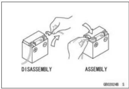
Battery Ground
Before completing any service on the motorcycle, disconnect the battery cables from the battery to prevent the engine from accidentally turning over. Disconnect the ground cable (−) first and then the positive (+). When completed with the service, first connect the positive (+) cable to the positive (+) terminal of the battery then the negative (−) cable to the negative terminal.
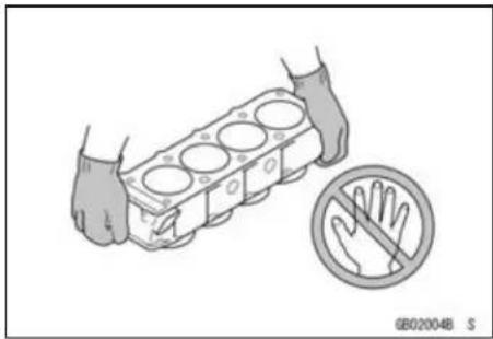
Edges of Parts
Lift large or heavy parts wearing gloves to prevent injury from possible sharp edges on the parts.
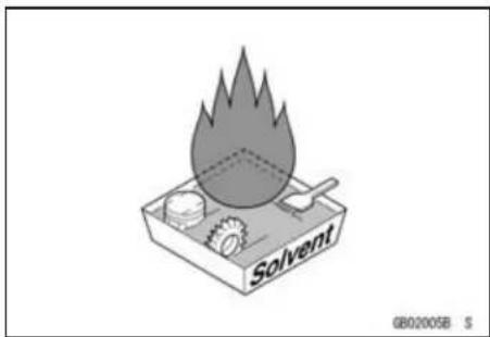
Solvent
Use a high-flash point solvent when cleaning parts. High-flush point solvent should be used according to directions of the solvent manufacturer.
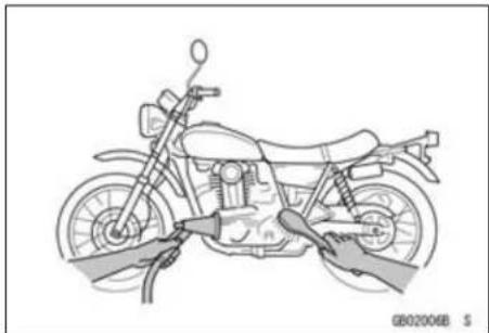
Cleaning vehicle before disassembly
Clean the vehicle thoroughly before disassembly. Dirt or other foreign materials entering into sealed areas during vehicle disassembly can cause excessive wear and decrease performance of the vehicle.
Before Servicing
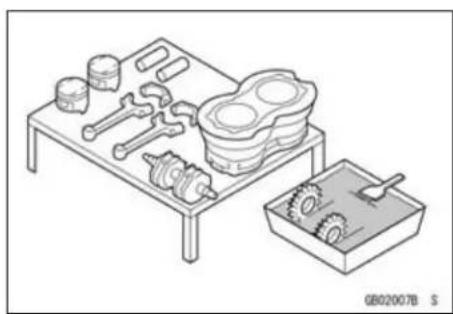
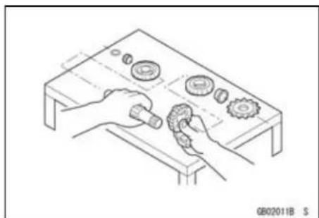
Arrangement and Cleaning of Removed Parts
Disassembled parts are easy to confuse. Arrange the parts according to the order the parts were disassembled and clean the parts in order prior to assembly.
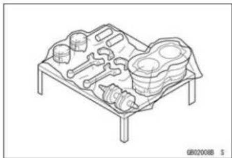
Storage of Removed Parts
After all the parts including subassembly parts have been cleaned, store the parts in a clean area. Put a clean cloth or plastic sheet over the parts to protect from any foreign materials that may collect before re-assembly.
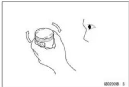
Inspection
Reuse of worn or damaged parts may lead to serious accident. Visually inspect removed parts for corrosion, discoloration, or other damage. Refer to the appropriate sections of this manual for service limits on individual parts. Replace the parts if any damage has been found or if the part is beyond its service limit.
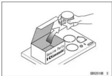
Replacement Parts
Replacement Parts must be KAWASAKI genuine or recommended by KAWASAKI. Gaskets, O-rings, Oil seals, Grease seals, circlips, cotter pins or self-locking nuts must be replaced with new ones whenever disassembled.
Assembly Order
In most cases assembly order is the reverse of disassembly, however, if assembly order is provided in this Service Manual, follow the procedures given.
1-4 GENERAL INFORMATION
Before Servicing
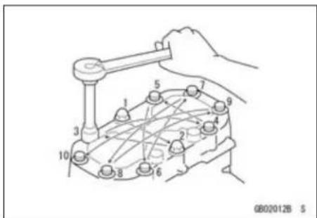
Tightening Sequence
Generally, when installing a part with several bolts, nuts, or screws, start them all in their holes and tighten them to a snug fit. Then tighten them according to the specified sequence to prevent case warpage or deformation which can lead to malfunction. Conversely when loosening the bolts, nuts, or screws, first loosen all of them by about a quarter turn and them remove them. If the specified tightening sequence is not indicated, tighten the fasteners alternating diagonally.
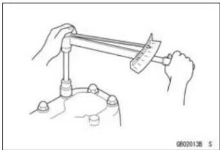
Tightening Torque
Incorrect torque applied to a bolt, nut, or screw may lead to serious damage. Tighten fasteners to the specified torque using a good quality torque wrench.
Often, the tightening sequence is followed twice-initial tightening and final tightening with torque wrench.
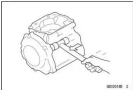
Force
Use common sense during disas sembly and assembly, excessive force can cause expensive or hard to repair damage. When necessary, remove screws that have a non-permanent locking agent applied using an impact driver. Use a plastic-faced mallet whenever tapping is necessary.
Gasket, O-ring
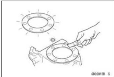
Hardening, shrinkage, or damage of both gaskets and O-rings after disassembly can reduce sealing performance. Remove old gaskets and clean the sealing surfaces thoroughly so that no gasket material or other material remains. Install new gaskets and replace used O-rings when re-assembling
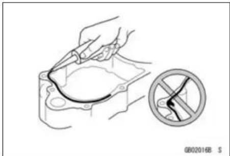
Liquid Gasket, Non-permanent Locking Agent
For applications that require Liquid Gasket or a Non-permanent Locking agent, clean the surfaces so that no oil residue remains before applying liquid gasket or Non-permanent locking agent. Do not apply them excessively. Excessive application can clog oil passages and cause serious damage.
Before Servicing
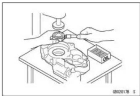
Press
For items such as bearings or oil seals that must be pressed into place, apply small amount of oil to the contact area. Be sure to maintain proper alignment and use smooth movements when installing.
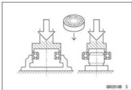
Ball Bearing and Needle Bearing
Do not remove pressed ball or needle unless removal is absolutely necessary. Replace with new ones whenever removed. Press bearings with the manufacturer and size marks facing out. Press the bearing into place by putting pressure on the correct bearing race as shown.
Pressing the incorrect race can cause pressure between the inner and outer race and result in bearing damage.
Oil Seal, Grease Seal
Do not remove pressed oil or grease seals unless removal is necessary. Replace with new ones whenever removed. Press new oil seals with manufacture and size marks facing out. Make sure the seal is aligned properly when installing.
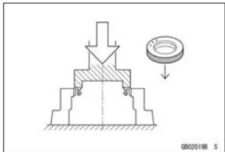
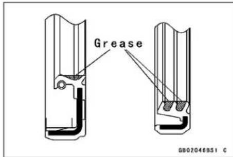
Apply specified grease to the lip of seal before installing the seal.
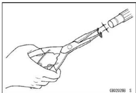
Circlips, Cotter Pins
Replace circlips or cotter pins that were removed with new ones. Take care not to open the clip excessively when installing to prevent deformation.
1-6 GENERAL INFORMATION
Before Servicing
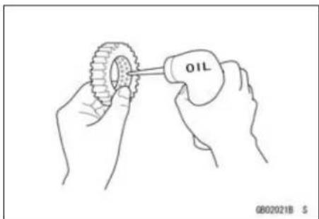
Lubrication
It is important to lubricate rotating or sliding parts during assembly to minimize wear during initial operation. Lubrication points are called out throughout this manual, apply the specific oil or grease as specified.
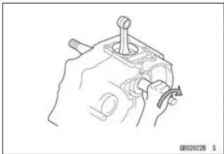
Direction of Engine Rotation
When rotating the crankshaft by hand, the free play amount of rotating direction will affect the adjustment. Rotate the crankshaft to positive direction (clockwise viewed from output side).
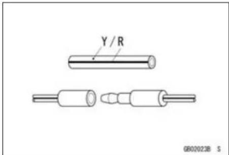
Electrical Leads
A two-color lead is identified first by the primary color and then the stripe color. Unless instructed otherwise, electrical leads must be connected to those of the same color.
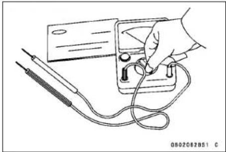
Instrument
Use a meter that has enough accuracy for an accurate measurement. Read the manufacture's instructions thoroughly before using the meter. Incorrect values may lead to improper adjustments.
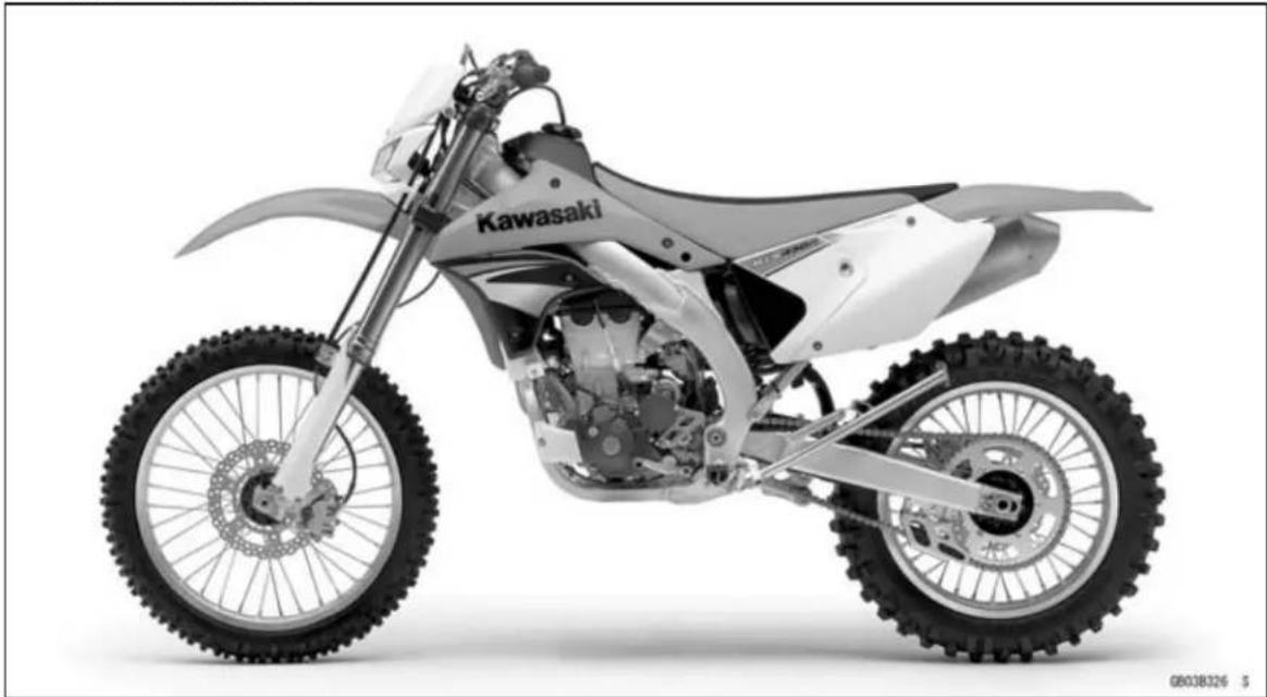
Model Identification
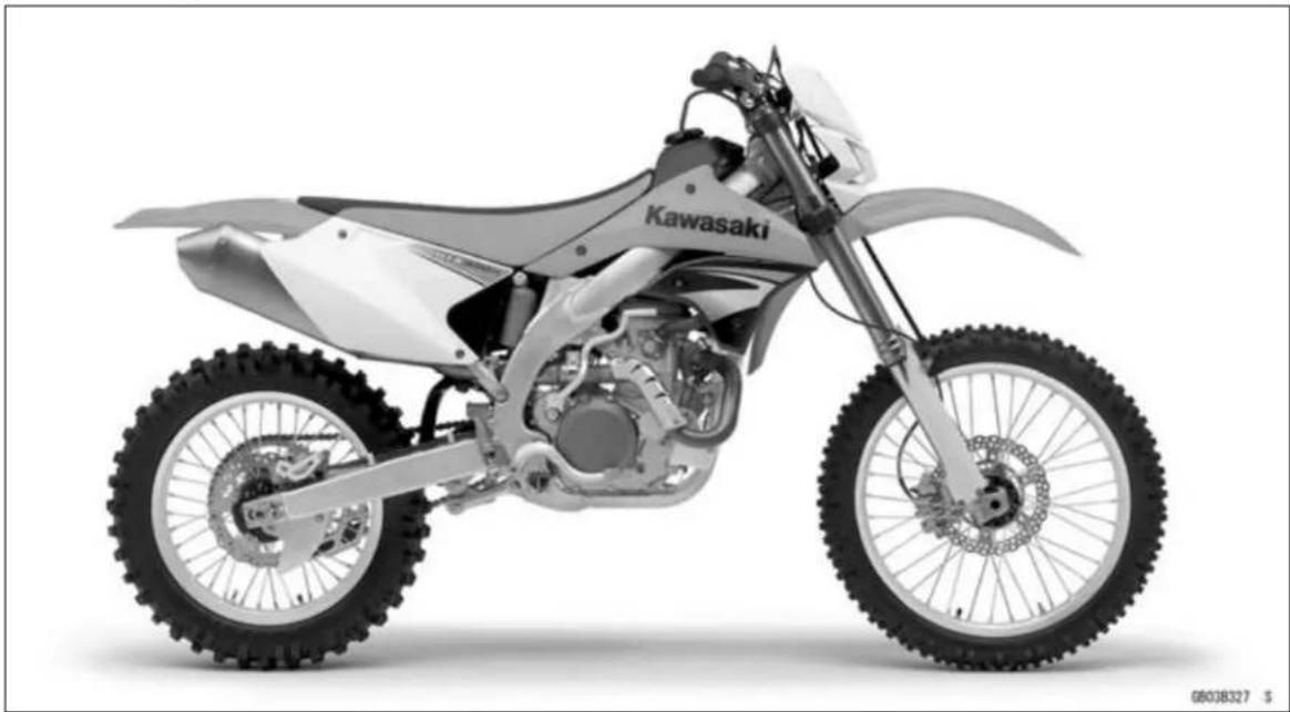
KLX450A8F Left Side View
KLX450A8F Right Side View
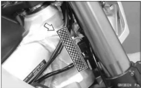
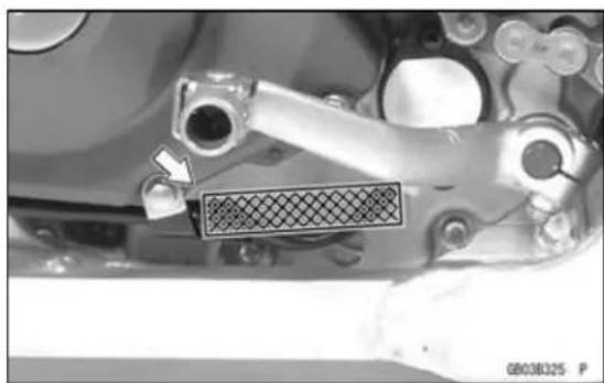
Frame Number Engine Number
1-8 GENERAL INFORMATION
General Specifications
| Items KLX450A8F ~ ABF | |
| Dimensions | |
| Overall Length | 2 180 mm (85.83 in.), (AU) (EUR) 2 175 mm (85.63 in.) |
| Overall Width 820 mm (32.3 in.) | |
| Overall Height | 1 255 mm (49.41 in.), (AU) (EUR) 1 250 mm (49.21 in.) |
| Wheelbase 1 480 mm (58.27 in.) | |
| Road Clearance | 320 mm (12.6 in.), (AU) (EUR) 315 mm (12.4 in.) |
| Seat Height | 940 mm (37.0 in.), (AU) (EUR) 935 mm (36.8 in.) |
| Dry Mass (KLX450A8F) 115 kg | (254 lb) |
| Curb Mass | (KLX450A9F ~ ABF) 126 kg (278 lb) |
| Fuel Tank Capacity 8 L (2.1 US gal) | |
| Performance | |
| Minimum Turning Radius | - |
| Engine | |
| Type | 4-stroke, single cylinder, DOHC 4 valve |
| Cooling System | Liquid-cooled |
| Bore and Stroke | 96.0 × 62.1 mm (3.78 × 2.44 in.) |
| Displacement | 449 cm 3 (27.4 cu in.) |
| Compression Ratio | 12.0 : 1 |
| Carburetion System | Carburetor, KEIHIN FCR-MX40 |
| Starting System | Electric starter, Primary kick |
| Ignition System | Digital AC-CDI |
| Timing Advance | |
| Ignition Timing | BTDC 10.2° @1 800 r/min (rpm) |
| Spark Plug | NGK CPR8EB-9 |
| Valve Timing: | |
| Intake: | |
| Open | BTDC 38° |
| Close | ABDC 66° |
| Duration | 284° |
| Exhaust: | |
| Open | BBDC 68° |
| Close | ATDC 36° |
| Duration | 284° |
| Lubrication System | Forced lubrication (semi-dry sump) |
| Engine Oil: | |
| Type | API SG, SH, SJ, SL or SM with JASO MA, MA1 or MA2 |
| Viscosity | SAE 10W-40 |
| Capacity | 1.3 L (1.4 US qt) |
| Drive Train | |
| Primary Reduction System: | |
| Type | Gear |
| Reduction Ratio | 2.727 (60/22) |
| Clutch Type | Wet, multi disc |
General Specifications
| Items KLX450A8F ~ ABF | |
| Transmission:Type 5-speed, constant mesh,Gear ratios:1st 2.167 (26/12)2nd 1.533 (23/15)3rd 1.188 (19/16)4th 0.950 (19/20)5th 0.810 (17/21)Final Drive System:Type Chain driveReduction Ratio 3.846 (50/13)Overall Drive Ratio 8.492 @Top gear | return shift |
| FrameType Tubular, semi-double cradleSteering AngleCaster (rake angle)TrailFront tire:SizeMake/TypeRear tire:SizeMake/TypeRim size:FrontRearFront suspension:Type Telescopic fork (up sidedown)Wheel travelRear suspension:Type Swingarm (New Uni-trak)Wheel travelBrake type:Front and RearEffective disc diameter:Front (effect. dia.)Rear (effect. dia.) | 42° to either side27.7°, (AU) (EUR) 28°122 mm (4.80 in.)80/100-21 51M, (AU) (EUR) 80/100-21 M/C 51PBRIDGESTONE M401, Tube type, (AU) (EUR) ED03, Tube type110/100-18 64M, (AU) (EUR) 120/90-18 M/C 65PBRIDGESTONE M402, Tube type, (AU) (EUR) ED04, Tube type21 × 1.6018 × 2.15down)305 mm (12.0 in.)315 mm (12.4 in.)Single disc225 mm (8.86 in.)215 mm (8.46 in.) |
| Electrical EquipmentBatteryHeadlight:Type Semi-sealed beamBulb | 12 V 6 Ah12 V 35 W |
1-10 GENERAL INFORMATION
General Specifications
| Items KLX450A8F | ~ ABF |
| Tail Light LEDMagneto:Rated Output 2.0 A / 14 V |
Specifications subject to change without notice, and may not apply to every country.
Unit Conversion Table
Prefixes for Units:
| Prefix Symbol Power | |
| mega M × 1 000 000kilo k × 1 000centi c × 0 . 0 1milli m × 0 . 0 0 1micro μ × 0.000001 |
Units of Mass:
| kg | × | 2.205 | = | lb |
| g | × | 0.03527 | = | oz |
Units of Volume:
| L | × | 0.2642 | = | gal (US) |
| L | × | 0.2200 | = | gal (imp) |
| L | × | 1.057 | = | qt (US) |
| L | × | 0.8799 | = | qt (imp) |
| L | × | 2.113 | = | pint (US) |
| L | × | 1.816 | = | pint (imp) |
| mL | × | 0.03381 | = | oz (US) |
| mL | × | 0.02816 | = | oz (imp) |
| mL | × | 0.06102 | = | cu in |
Units of Force:
| N | × | 0.1020 | = | kgf |
| N | × | 0.2248 | = | lb |
| kgf | × | 9.807 | = | N |
| kgf | × | 2.205 | = | lb |
Units of Length:
| km | × | 0.6214 | = | mile |
| m × | 3.281 | = | ft | |
| mm | × | 0.03937 | = | in |
Units of Torque:
| N·m | × | 0.1020 | = | kgf·m |
| N·m | × | 0.7376 | = | ft·lb |
| N·m | × | 8.851 | = | in·lb |
| kgf·m | × | 9.807 | = | N·m |
| kgf·m | × | 7.233 | = | ft·lb |
| kgf·m | × | 86.80 | = | in·lb |
Units of Pressure:
| kPa × | 0.01020 = | kgf/cm 2 | ||
| kPa × | 0.1450 = | psi | ||
| kPa | × | 0.7501 | = | cm Hg |
| kgf/cm 2 | × | 98.07 | = | kPa |
| kgf/cm 2 | × | 14.22 | = | psi |
| cm Hg | × | 1.333 | = | kPa |
Units of Speed:
| km/h | × | 0.6214 | = | mph |
Units of Power:
| kW | × | 1.360 | = | PS |
| kW | × | 1.341 | = | HP |
| PS | × | 0.7355 | = | kW |
| PS | × | 0.9863 | = | HP |
Units of Temperature:
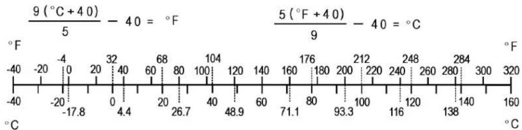
Periodic Maintenance
Table of Contents
Periodic Maintenance Chart...... 2-2
Torque and Locking Agent.... 2-4
Specifications 2-9
Special Tools 2-11
Periodic Maintenance Procedures..... 2-12
Fuel System.... 2-12
Fuel Hose and Connection Inspection.... 2-12
Throttle Grip Free Play Inspection 2-12
Throttle Grip Free Play Adjustment 2-12
Hot Starter Lever Free Play Inspection.... 2-13
Idle Speed Inspection 2-13
Idle Speed Adjustment.... 2-14
Air Cleaner Element Cleaning and Inspection.... 2-14
Fuel Inspection.... 2-16
Fuel Tank, Filter and Tap Cleaning.... 2-17
Fuel Tap and Filter Inspection..... 2-17
Cooling System.... 2-17
Coolant Level Inspection.... 2-18
Coolant Deterioration Inspection.. 2-18
Radiator Hoses and Connections Inspection.... 2-19
Engine Top End 2-19
Vacuum Switch Valve Test 2-19
Valve Clearance Inspection ..... 2-20
Valve Clearance Adjustment...... 2-21
Cylinder Head Warp Inspection ... 2-23
Cylinder Wear Inspection 2-23
Piston/Cylinder Clearance 2-24
Piston, Piston Ring and Piston Pin Replacement.... 2-24
Spark Arrester Cleaning.... 2-24
Engine Right Side 2-25
Clutch Lever Free Play Check..... 2-25
Clutch Lever Free Play Adjustment 2-26
Friction and Steel Plates Inspection.... 2-26
Engine Lubrication System...... 2-26
Engine Oil Change.... 2-26
Oil Filter Change 2-27
Breather Hose Inspection 2-28
Crankshaft/Transmission 2-29
Crankshaft Inspection 2-29
Wheel/Tires 2-29
Air Pressure Inspection/Adjustment 2-29
Tires Inspection.... 2-30
Spoke Tightness Inspection...... 2-30
Rim Runout Inspection.... 2-31
Wheel Bearing Inspection...... 2-31
Final Drive.... 2-32
Drive Chain Slack Inspection ..... 2-32
Drive Chain Slack Adjustment ..... 2-32
Drive Chain Wear Inspection ..... 2-33
Drive Chain Lubrication.... 2-34
Sprocket Wear Inspection...... 2-34
Rear Sprocket Warp Inspection... 2-35
Brakes.... 2-35
Brake Lever and Pedal Position Adjustment 2-35
Brake Fluid Level Inspection...... 2-36
Brake Fluid Change.... 2-37
Brake Pad Wear Inspection ..... 2-39
Brake Master Cylinder Cup and Dust Seal Replacement .... 2-39
Caliper Piston Seal and Dust Seal Replacement.... 2-41
Brake Hose and Connection Check.... 2-44
Brake Hose Replacement...... 2-44
Suspension 2-45
Front Fork Inspection 2-45
Front Fork Oil Change (each fork leg) 2-45
Rear Shock Absorber Inspection . 2-54
Rear Shock Absorber Oil Change 2-54
Swingarm and Uni-Trak Linkage Inspection.... 2-59
Swingarm and Uni-Track Linkage Pivot Lubricate 2-59
Steering 2-59
Steering Inspection 2-59
Steering Adjustment 2-59
Stem Bearing Lubrication.... 2-61
Frame 2-61
Frame Inspection 2-61
Electrical System 2-62
Spark Plug Cleaning and Inspection.... 2-62
Cable Inspection 2-62
Lubrication 2-62
Nut, Bolt, and Fastener Tightness Inspection.... 2-63
Tightness Inspection.... 2-63
Periodic Maintenance Chart
The maintenance must be done in accordance with this chart to keep the motorcycle in good running condition.
Periodic Inspection
| FREQUENCY | Traveled Distance km (mi) | See Page | |||||
| Every 100 (60) or 2.5 hr | Every 500 (300) or 7.5 hr | Every 1 000 (600) or 15 hr | Every 1 500 (900) or 30 hr | Every 2 000 (1 200) or 60 hr | |||
| OPERATION | |||||||
| ENGINE | Spark plug-clean, gap † Every 500 km (300 mi) | 2 - 6 2 | |||||
| Spark plug-inspect † | ● ● | ● ● | 2 - 62 | ||||
| Clutch cable-adjust Every 100 km (60 mi) 2 - 2 6 | |||||||
| Clutch and friction plates-inspect † | ● | ● ● | ● ● | 2 - 26 | |||
| After 2 000 km (1 200 mi), every 1 000 km (600 mi) | |||||||
| Throttle cable-adjust | Every 100 km (60 mi) | 2 - 12 | |||||
| Air cleaner element-clean † | ● | ● ● | ● ● | 2 - 14 | |||
| After 2 000 km (1 200 mi), every 1 000 km (600 mi) | |||||||
| Carburetor-inspect and adjust | ● | ● ● | ● ● | 2 - 13 | |||
| Cylinder head, cylinder-inspect | ● | ● | 2 - 23 | ||||
| Valve clearance-inspect † | ● | ● | ● | 2 - 20 | |||
| After 2 000 km (1 200 mi), every 1 000 km (600 mi) | |||||||
| Hot starter cable-adjust | Every 100 km (60 mi) 2 - 1 3 | ||||||
| Spark arrester-clean | Every 6 000 km (3 750mi) | 2 - 24 | |||||
| Vacuum switch valve-inspect † | ● | ● | 2 - 19 | ||||
| Kick pedal and shift pedal-clean | ● | ● ● | ● ● | - | |||
| Engine sprocket-inspect † | ● | ● ● | ● ● | 2 - 34 | |||
| Coolant-inspect † | ● | ● ● | ● ● | 2 - 18 | |||
| Radiator hoses and connections-inspect † | ● | ● ● | ● ● | 2 - 19 | |||
| Crankshaft-inspect | ● | ● | 2 - 29 | ||||
| Breather hose-inspect | ● | ● ● | ● ● | 2 - 28 | |||
| CHASSIS | Brake adjustment-inspect † | ● | ● ● | ● ● | 2 - 35 | ||
| Brake pad wear-inspect † | ● | ● ● | ● ● | 2 - 39 | |||
| Brake fluid level-inspect † | ● | ● ● | ● ● | 2 - 36 | |||
| Brake hoses, connections-inspect † | ● | ● ● | ● ● | 2 - 44 | |||
| Spoke tightness and rim runout-inspect † | ● | ● ● | ● ● | 2 - 30 | |||
| Wheel bearing-inspect † | ● | ● ● | ● ● | 2 - 31 | |||
| Frame-inspect and clean | ● | ● ● | ● ● | 2 - 61 | |||
| Drive chain wear-inspect † | ● | ● ● | ● ● | 2 - 33 | |||
| Drive chain-inspect and adjust | ● | ● ● | ● ● | 2 - 32 | |||
| Drive chain-lubricate | ● | ● ● | ● ● | 2 - 34 | |||
| Wheels/tires-inspect | ● | ● ● | ● ● | 2 - 30 | |||
Periodic Maintenance Chart
| FREQUENCY | Traveled Distance km (mi) | See Page | |||||
| Every 100 (60) or 2.5 hr | Every 500 (300) or 7.5 hr | Every 1 000 (600) or 15 hr | Every 1 500 (900) or 30 hr | Every 2 000 (1 200) or 60 hr | |||
| OPERATION | |||||||
| CHASSIS | Rear sprocket-inspect † | ● ● | ● ● ● | 2 - 35 | |||
| Front fork-inspect and clean | ● ● | ● ● ● | 2 - 45 | ||||
| Cable-inspect | ● ● | ● ● ● | 2 - 62 | ||||
| Fuel hose, connections-inspect † | ● ● | ● ● | 2 - 12 | ||||
| Fuel system-clean | ● ● | ● ● ● | 2 - 17 | ||||
| Steering play-inspect † | ● ● | ● ● ● | 2 - 59 | ||||
| Steering stem bearing-grease | ● | ● | 2 - 61 | ||||
| Swingarm and Uni-Trak linkage pivots-grease | ● ● | ● ● | 2 - 59 | ||||
| Swingarm and Uni-Trak linkage pivots-inspect † | ● ● | ● ● | 2 - 59 | ||||
| Nuts, bolts, fasteners-inspect † | ● ● | ● ● ● | 2 - 63 | ||||
| Rear shock absorber-inspect | ● ● | ● ● ● | 2 - 54 | ||||
| Chassis parts-lubricate | ● ● | ● ● ● | - | ||||
†: Replace, add, adjust, clean or torque if necessary.
Periodic Replacement Parts
| FREQUENCY OPERATION | Traveled Distance km (mi) | See Page | ||||
| Every 100 (60) or 2.5 hr | Every 500 (300) or 7.5 hr | Every 1 000 (600) or 15 hr | Every 1 500 (900) or 30 hr | Every 2 000 (1 200) or 60 hr | ||
| Engine oil-change | Every 1 000 km (600 mi) | 2 - 26 | ||||
| Piston and piston ring-replace | Every 1 500 km (900 mi) | 2 - 24 | ||||
| Piston pin-replace | Every 1 500 km (900 mi) | 2 - 24 | ||||
| Oil filter-replace | Every 1 000 km (600 mi) | 2 - 27 | ||||
| Brake fluid-change | Every 2 years | 2 - 3 7 | ||||
| Brake master cylinder cup and dust seal-replace | Every 2 years | 2 - 39 | ||||
| Brake caliper piston seal and dust seal-replace | Every 2 years | 2 - 41 | ||||
| Brake hoses-replace | Every 4 years | 2 - 44 | ||||
| Front fork oil-change | ● | ● | 2 - 45 | |||
| Rear shock oil-replace | ● | ● | 2 - 54 | |||
| Fuel hose-replace | Every 4 years | 2 - 12 | ||||
2-4 PERIODIC MAINTENANCE
Torque and Locking Agent
Tighten all bolts and nuts to the proper torque using an accurate torque wrench. If insufficiently tightened, a bolt or nut may become damaged, strip an internal thread, or break and then fall out. The following table lists the tightening torque for the major bolts and nuts, and the parts requiring use of a non-permanent locking agent or liquid gasket.
When checking the tightening torque of the bolts and nuts, first loosen the bolt or nut by half a turn and then tighten to specified torque.
Letters used in the "Remarks" column mean:
AL: Tighten the two clamp bolts alternately two times to ensure even tightening torque.
HL: Apply high-locking agent.
L: Apply a non-permanent locking agent to the threads.
Lh: Left-hand Threads
MO: Apply molybdenum disulfide oil.
S: Tighten the fasteners following the specified sequence.
Si: Apply Silicone grease.
R: Replacement Parts
2T: Apply 2-stroke oil.
T: First, tighten the stem locknut with 39 N·m (4.0 kgf·m, 29 ft·lb) of torque, then loosen it and retighten it with 4.9 N·m (0.50 kgf·m, 43 in·lb) of torque.
| Fastener | Torque | Remarks | ||
| N·m kgf | ·m ft·lb | |||
| Fuel System | ||||
| Throttle Pulley Cover Bolt 3.4 0.35 30 in·lb | ||||
| Throttle Cable Mounting Bolts | 6.9 | 0.70 | 61 in·lb | |
| Vacuum Switch Valve Bracket Bolts | 9.8 | 1.0 | 87 in·lb | |
| Fuel Tap Knob Screws | 0.80 | 0.080 | 7.0 in·lb | |
| Rear Frame Mounting Bolts | 34 | 3.5 | 25 | |
| Cooling System | ||||
| Water Pump Cover Bolts | 9.8 | 1.0 | 87 in·lb | |
| Coolant Drain Plug | 7.0 | 0.70 | 62 in·lb | |
| Water Pump Impeller Bolt | 9.8 | 1.0 | 87 in·lb | |
| Right Engine Cover Bolts | 9.8 | 1.0 | 87 in·lb | |
| Radiator Hose Clamp Screws | 3.0 | 0.30 | 27 in·lb | |
| Engine Top End | ||||
| Cylinder Head Cover Bolts | 9.8 | 1.0 | 87 in·lb | |
| Cylinder Head Bolts (M10) | 59 | 6.0 | 44 | S, MO |
| Cylinder Head Bolts (M6) | 12 | 1.2 | 106 in·lb | S |
| Cylinder Bolt | 12 | 1.2 | 106 in·lb | |
| Camshaft Cap Bolts | 9.8 | 1.0 | 87 in·lb | S, MO |
| Camshaft Sprocket Bolts | 12 | 1.2 | 106 in·lb | L |
| Carburetor Holder Clamp Screws | 2.0 | 0.20 | 18 in·lb | |
| Plug | 20 | 2.0 | 15 | L |
| Rear Camshaft Chain Guide Bolt | 15 | 1.5 | 11 | |
| Oil Pump (Scavenge) Cover Bolts | 9.8 | 1.0 | 87 in·lb | |
| Chain Tensioner Mounting Bolts | 9.8 | 1.0 | 87 in·lb | |
| Chain Tensioner Cap Bolt | 5.0 | 0.51 | 44 in·lb | |
| Water Hose Fitting Bolts | 9.8 | 1.0 | 87 in·lb | |
| Oil Line Plug | 3.0 | 0.31 | 27 in·lb | L |
| Decompressor Plug Plate Bolt | 9.8 | 1.0 | 87 in·lb | |
Torque and Locking Agent
| Fastener | Torque | Remarks | ||
| N·m kgf | m ft·lb | |||
| Vacuum Hose Fitting 8.8 0.90 78 in·lb L | ||||
| Cylinder Head Pipe Mounting Bolt | 9.8 | 1.0 | 87 in·lb | |
| Exhaust Pipe Cover Bolts | 12 | 1.2 | 106 in·lb | |
| Rear Muffler Mounting Bolt | 20 | 2.0 | 15 | |
| Front Muffler Mounting Bolt (First) | 9.8 | 1.0 | 87 in·lb | |
| Front Muffler Mounting Bolt (Final) | 20 | 2.0 | 15 | |
| Exhaust Pipe Holder Nuts | 20 | 2.0 | 15 | |
| Muffler End Mounting Bolts | 10 | 1.0 | 89 in·lb | |
| Spark Arrester Mounting Bolts | 10 | 1.0 | 89 in·lb | |
| Engine Right Side | ||||
| Primary Gear Nut | 98 | 10 | 72 | Lh,R |
| Clutch Cover Bolts | 9.8 | 1.0 | 87 in·lb | |
| Right Engine Cover Bolts | 9.8 1.0 | 87 in·lb | ||
| Clutch Spring Bolts | 8.8 0.90 | 78 in·lb | ||
| Clutch Hub Nut | 98 | 10 | 72 | R |
| Ratchet Guide Bolt | 8.8 0.90 | 78 in·lb | ||
| Kick Pedal Bolt | 25 | 2.5 | 18 | L |
| Ratchet Plate Mounting Bolt | 9.8 | 1.0 | 87 in·lb | S |
| Ratchet Plate Mounting Screw | 6.4 | 0.65 | 56 in·lb | L,S |
| Gear Set Lever Nut | 8.8 0.90 | 78 in·lb | ||
| Shift Drum Cam Bolt | 24 | 2.4 | 18 | L |
| Engine Lubrication System | ||||
| Engine Oil Drain Plug (M10) (Main) | 20 | 2.0 | 15 | |
| Engine Oil Drain Plug (M6) (Sub) | 7.0 | 0.71 | 62 in·lb | |
| Oil Pump (Scavenge) Cover Bolts | 9.8 | 1.0 | 87 in·lb | |
| Oil Pump (Feed) Cover Bolts | 9.8 | 1.0 | 87 in·lb | |
| Right Engine Cover Bolts | 9.8 | 1.0 | 87 in·lb | |
| Piston Oil Nozzle | 5.0 | 0.50 | 44 in·lb | |
| Oil Filter Cover Bolt | 9.8 | 1.0 | 87 in·lb | |
| Oil Screen (Feed) Mounting Bolts | 9.8 | 1.0 | 87 in·lb | |
| Oil Pressure Relief Valve | 15 | 1.5 | 11 | HL |
| Breather Fitting | 15 | 1.5 | 11 | L |
| Oil Filler Cap | - | - | - | Hand-tighten |
| Engine Removal/Installation | ||||
| Upper Engine Mounting Bolts (M10) | 49 | 5.0 | 36 | |
| Middle Engine Mounting Nut (M10) | 49 | 5.0 | 36 | R |
| Lower Engine Mounting Nut (M10) | 49 | 5.0 | 36 | R |
| Upper Engine Bracket Bolts (M8) | 29 | 3.0 | 21 | |
| Middle Engine Bracket Nuts (M8) | 29 | 3.0 | 21 | R |
| Swingarm Pivot Shaft Nut | 98 | 10 | 72 | R |
| Crankshaft/Transmission | ||||
| Crankcase Bolts (M6) | 12 | 1.2 | 106 in·lb | S |
| Crankcase Bolts (M7) | 15 | 1.5 | 11 | S |
Torque and Locking Agent
| Fastener | Torque | Remarks | ||
| N·m kgf | m ft·lb | |||
| Gear Set Lever Nut 8.8 0.90 78 in·lb | ||||
| Engine Oil Drain Plug (M6)(Sub) | 7.0 | 0.71 | 62 in·lb | |
| Engine Oil Drain Plug (M10)(Main) | 20 | 2.0 | 15 | |
| Shift Drum Cam Bolt 24 2.4 18 L | ||||
| Piston Oil Nozzle 4.0 0.41 35 in·lb | ||||
| Bearing Retaining Screws | 15 | 1.5 | 11 | L |
| Balancer Weight Mounting Nut | 52 | 5.3 | 38 | |
| Gear Position Switch Screws | 2.9 | 0.30 | 26 in·lb | L |
| Wheels/Tires | ||||
| Spoke Nipples | 2.2 0.22 | 19 in·lb | ||
| Front Axle Nut | 79 8.0 | 58 | ||
| Front Axle Clamp Bolts | 20 | 2.0 | 15 | AL |
| Rear Axle Nut | 110 | 11.2 | 81.1 | |
| Final Drive | ||||
| Rear Sprocket Nuts | 34 3.5 | 25 | R | |
| Engine Sprocket Nut | 127 | 13.0 | 93.7 | |
| Brakes | ||||
| Front Master Cylinder Clamp Bolts | 8.8 | 0.90 | 78 in·lb | S |
| Brake Hose Banjo Bolts | 25 2.5 | 18 | ||
| Brake Pad Bolt | 17 1.7 | 13 | ||
| Caliper Bleed Valve | 7.8 | 0.80 | 69 in·lb | |
| Caliper Mounting Bolts | 25 2.5 | 18 | ||
| Front Brake Disc Mounting Bolts | 10 | 1.0 | 89 in·lb | L |
| Brake Lever Pivot Bolt Locknut | 5.9 | 0.60 | 52 in·lb | |
| Brake Lever Pivot Bolt | 5.9 | 0.60 | 52 in·lb | Si |
| Brake Reservoir Cap Screws | 1.5 | 0.15 | 13 in·lb | |
| Front Brake Light Switch Screw | 1.2 | 0.12 | 10 in·lb | |
| Brake Hose Banjo Bolts | 25 2.5 | 18 | ||
| Rear Master Cylinder Mounting Bolts | 10 | 1.0 | 89 in·lb | |
| Rear Master Cylinder Push Rod Locknut | 17 | 1.7 | 13 | |
| Caliper Bleed Valve | 7.8 | 0.80 | 69 in·lb | |
| Brake Pad Bolt | 17 1.7 | 13 | ||
| Rear Brake Pad Bolt Plug | 2.4 | 0.24 | 21 in·lb | |
| Caliper Holder Shaft | 27 | 2.8 | 20 | Si |
| Brake Pedal Mounting Bolt | 25 | 2.5 | 18 | G,L |
| Rear Brake Disc Mounting Bolts | 23 | 2.3 | 17 | L |
| Brake Reservoir Cap Bolts | 1.5 | 0.15 | 13 in·lb | |
| Suspension | ||||
| Base Valve Assembly | 28 2.9 | 21 | ||
| Front Fork Top Plug 30 3.1 22 | ||||
| Front Fork Clamp Bolts (Upper) | 20 | 2.0 | 15 | AL |
| Front Fork Clamp Bolts (Lower) | 20 | 2.0 | 15 | AL |
| Steering Stem Head Nut | 98 | 10 | 72 | |
Torque and Locking Agent
| Fastener | Torque | Remarks | ||
| N·m kgf | m ft·lb | |||
| Locknut/Adjuster Assembly | 29 3.0 | 21 | ||
| Adjuster Assembly 55 5.6 41 L | ||||
| Front Axle Clamp Bolts | 20 | 2.0 | 15 | AL |
| Swingarm Pivot Shaft Nut | 98 | 10 | 72 | R |
| Rocker Arm Pivot Nut | 59 | 6.0 | 44 | R |
| Tie-rod Mounting Nut (Front, Rear) | 59 | 6.0 | 44 | R |
| Rear Shock Absorber Mounting Nut (Upper) | 39 4.0 | 29 | R | |
| Rear Shock Absorber Mounting Nut (Lower) | 34 3.5 | 25 | R | |
| Air Bleed Bolt | 6.5 | 0.66 | 58 in·lb | |
| Steering | ||||
| Handlebar Clamp Bolts | 25 | 2.5 | 18 | 2T |
| Steering Stem Head Nut | 98 | 10 | 72 | |
| Steering Stem Nut | 4.9 | 0.50 | 43 in·lb | T |
| Front Fork Clamp Bolts (Upper) | 20 | 2.0 | 15 | AL |
| Front Fork Clamp Bolts (Lower) | 20 | 2.0 | 15 | AL |
| Frame | ||||
| Rear Frame Mounting Bolt | 34 | 3.5 | 25 | |
| Upper Footpeg Bracket Bolts | 54 | 5.5 | 40 | L |
| Sidestand Nut | 29 | 3.0 | 21 | R |
| Electrical System | ||||
| Spark Plug | 13 | 1.3 | 115 in·lb | |
| Starter Motor Terminal Nut | 5.9 | 0.60 | 52 in·lb | |
| Starter Motor Mounting Bolts | 9.8 | 1.0 | 87 in·lb | |
| Crankshaft Sensor Bolts | 7.0 | 0.71 | 62 in·lb | |
| Stator Bolts | 4.0 | 0.41 | 35 in·lb | L |
| Flywheel Nut | 98 10 | 72 | ||
| Magneto Cover Bolts | 9.8 | 1.0 | 87 in·lb | |
| Timing Inspection Cap | - | - | - | Hand-Tighten |
| Flywheel Nut Cap | - | - | - | Hand-Tighten |
| Torque Limiter Cover Bolts | 9.8 | 1.0 | 87 in·lb | |
| Starter Motor Terminal Locknut | 6.9 | 0.70 | 61 in·lb | |
| Starter Motor Through Bolts | 3.4 | 0.35 | 30 in·lb | |
| Breather Fitting | 15 | 1.5 | 11 | L |
| Head Light Bracket Screws | 1.4 | 0.14 | 12 in·lb | |
| Gear Position Switch Screws | 2.9 | 0.30 | 26 in·lb | L |
2-8 PERIODIC MAINTENANCE
Torque and Locking Agent
Basic Torque for General Fasteners
| Threads dia. Torque | |||
| (mm) N·m kgf·m ft·lb | |||
| 5 | 3.4 ~ 4.9 | 0.35 ~ 0.50 | 30 ~ 43 in·lb |
| 6 | 5.9 ~ 7.8 | 0.60 ~ 0.80 | 52 ~ 69 in·lb |
| 8 | 14 ~ 19 | 1.4 ~ 1.9 | 10.0 ~ 13.5 |
| 10 | 25 ~ 34 | 2.6 ~ 3.5 | 19.0 ~ 25 |
| 12 | 44 ~ 61 | 4.5 ~ 6.2 | 33 ~ 45 |
| 14 | 73 ~ 98 | 7.4 ~ 10.0 | 54 ~ 72 |
| 16 | 115 ~ 155 | 11.5 ~ 16.0 | 83 ~ 115 |
| 18 | 165 ~ 225 | 17.0 ~ 23.0 | 125 ~ 165 |
| 20 | 225 ~ 325 | 23 ~ 33 | 165 ~ 240 |
Specifications
| Item Standard Service Limit | ||
| Fuel SystemThrottle Grip Free PlayHot Starter Lever Free PlayAir Cleaner Element Oil | 2 ~ 3 mm (0.08 ~ 0.12 in.)0.5 ~ 1.0 mm (0.02 ~ 0.04 in.)High quality foam air filter oil | - - - - - - - - - - - - - - - - - - - - - - - - - - - - - - - - - - - - - - - - - - - - - - - - - - - - - - - - - - - - - - - - - - - - - - - - - - - - - - - - - - - - - - - - - - - - - - - - - - - - - |
| Cooling SystemCoolant:Type (recommended)Color GreenMixed RatioFreezing PointTotal Amount | Permanent type antifreezeSoft water 50% and coolant 50%-35 °C (-31 °F)1.05 L (1.11 US qt) | - - - - - - - - - - - - - - - - - - - - - - - - - - - - - - - - - - - - - - - - - - - - - - - - - - - - - - - - - - - - - - - - - - - - - - - - - - - - - - - - - - - - - - - - - - - - - - - - - - |
2-10 PERIODIC MAINTENANCE
Specifications
| Item Standard Service Limit | ||
| Standard Tire:Front:Size 80/100-21 51M - - -(AU) (EUR) 80/100-21 M/C 51PMake BRIDGESTONE - -(AU) (EUR) ED03, Tube - -(AU) (EUR)120/90-18 M/C 65P - -(AU) (EUR) ED04, Tube - -(AU) (EUR) ED04, Tube - -(AU) (EUR) ED04, Tube - -(AU) (EUR) ED04, Tube - -(AU) (EUR) ED04, Tube - -(AU) (EUR) ED04, Tube - -(AU) (EUR) ED04, Tube - -(AU) (EUR) ED04, Tube - -(AU) (EUR) ED04, Tube - -(AU)(AUD) (AUD) (AUD) (AUD) (AUD) (AUD) (AUD) (AUD) (AUD) (AUD) (AUD) (AUD) (AUD) (AUD) (AUD) (AUD) (AUD) (AUD) (AUD) (AUD) (AUD) (AUD) (AUD) (AUD) (AUD) (AUD) (AUD) (AUD) (AUD) (AUD) (AUD) (AUD) (AUD) (AUD) (AUR) (AUD) (AUD) (AUD) (AUD) (AUD) (AUD) (AUD) (AUD) (AUD) (AUD) (AUD) (AUD) (AUD) (AUD) (AUD) (AUD) (AUD) (AUD) (AUD) (AUD) (AUD) (AUD) (AUD) (AUD) (AUD) (AUD) (AUD) (AUD) (AUD) (AUD) (AUD) (AUD) (AUD), (AUD) (AUD) (AUD) (AUD) (AUD) (AUD) (AUD) (AUD) (AUD) (AUD) (AUD) (AUD) (AUD) (AUD) (AUD) (AUD) (AUD) (AUD) (AUD) (AUD) (AUD) (AUD) (AUD) (AUD) (AUD) (AUD) (AUD) (AUD) (AUD) (AUD) (AUD) (AUD) (AUD) | (AU) (EUR) 80/100-21 M/C 51P-(AU) (EUR) ED03, Tube - -(AU) (EUR)120/90-18 M/C 65P - -(AU) (EUR) ED04, Tube - -(AU) (EUR) ED04, Tube - -(AU) (EUR) ED04, Tube - -(AU) (EUR) ED04, Tube - -(AU) (EUR) ED04, Tube - -(AU) (EUR)ED04, Tube - -(AU) (EUR) ED04, Tube - -(AU) (EUR) ED04, Tube - -(AU) (EUR) ED04, Tube - -(AU) (EUR) ED04, Tube - -(AU) (EUR) ED04, Tube - -(AU) (EUR) ED04, Tube - -(AU) (EUR) ED04, Tube - -(AU) (EUR) ED04, tube - -(AU) (EUR) ED04, tube - -(AU) (EUR) ED04, tube - -(AU) (EUR) ED04, tube - -(AU) (EUR) ED04, tube - -(AU) (EUR) ED04, tube - -(AU) (EUR) ED04, tube - -(AU) (EUR) ED04, tube - -(AU) (EUR) ED04, tube - -(AU)(AUD) (AUD) (AUD) (AUD) (AUD) (AUD) (AUD) (AUD) (AUD) (AUD) (AUD) (AUD) (AUD) (AUD) (AUD) (AUD) (AUD) (AUD) (AUD) (AUD) (AUD) (AUD) (AUD) (AUD) (AUD) (AUD) (AUD) (AUD) (AUD) (AUD) (AUD) (AUD) | - - - - - - - - - - - - - - - - - - - - - - - - - - - - - - - - - - - - - - - - - - - - - - - - - - - - - - - - - - - - - - - - - - - - - - - - - - - - - - - - - - - - - - - - - - - - - - - - - - - - - |
| Rear:Size 110/100-18 64M - -(AU) (EUR)120/90-18 M/C 65P - -(AU) (EUR)120/90-18 M/C 65P - -(AU) (EUR)120/90-18 M/C 65P - -(AU) (EUR)120/90-18 M/C 65P - -(AU) (EUR)120/90-18 M/C 65P - -(AU) (EUR)120/18 64M - -(AU) (EUR)120/90-18 M/C 65P - -(AU) (EUR)120/90-18 M/C 65P - -(AU) (EUR)120/90-18 M/C 65P - -(AU) (EUR)120/90-18 M/C 65P - -(AU) (EUR)120/90-18 M/C 65P - -(AU) (EUR)120/90-18 M/C 65P - -(AU) (EUR)120/90-18 M/C 65P - -(AU) (EUR)120/90-18 M/C 65P - -(AU) (EUR)120/90-18 M(C 65P - -(AU) (EUR)120/90-18 M/C 65P - -(AU) (EUR)120/90-18 M/C 65P - -(AU) (EUR)120/90-18 M/C 65P - -(AU) (EUR)120/90-18 M/C 65P - -(AU) (EUR) 120/90-18 M/C 65P - -(AU) (EUR)120/90-18 M/C 65P - -(AU) (EUR)120/90-18 M/C 65P - -(AU) (EUR)120/90-18 M/C 65P - -(AU) (EUR)120/90-18 M/C( 65P - -(AU) (EUR)120/90-18 M/C 65P - -(AU) (EUR)120/90-18 M/C 65P - -(AU) (EUR)120/90-18 M/C 65P - -(AU) (EUR)120/90-18 M/C 65P - -(AU) (EUR) (EUR)120/90-18 M/C 65P - -(AU) (EUR)120/90-18 M/C 65P - -(AU) (EUR)120/90-18 M/C 65P - -(AU) (EUR)120/90-18 M/C 65P - -(AU) (EUR)120/90- (AUD) (AUD) (AUD) (AUD) (AUD) (AUD) (AUD) (AUD) (AUD) (AUD) (AUD) (AUD) (AUD) (AUD) (AUD) (AUD) (AUD) (AUD) (AUD) (AUD) (AUD) (AUD) (AUD) (AUD) (AUD) (AUD) (AUD) (AUD) (AUD) (AUD) (AUD) (AUD) (AUD) | ||
| Final DriveDrive Chain SlackDrive Chain 20 Link LengthRear Sprocket Warp | 52 ~ 58 mm (2.0 ~ 2.3 in.)317.5 ~ 318.2 mm (12.50 ~ 12.53 in.)0.4 mm (0.016 in.) or less | - - - -323 mm (12.7 in.)0.5 mm (0.020 in.) |
| BrakesBrake Lever Free PlayBrake Fluid:Type:FrontRearBrake pad lining thickness:FrontRear | (to suit rider)DOT3 or DOT4DOT43.8 mm (0.15 in.)6.4 mm (0.25 in.) | - - - -- - - - - - - - - - - - - - - - - - - - - - - - - - - - - - - - - - - - - - - - - - - - - - - - - - - - - - - - - - - - - - - - - - - - - - - - - - - - - - - - - - - - - - - - - - - - - - - - - - - |
TIR: Total Indicator Readings
Special Tools
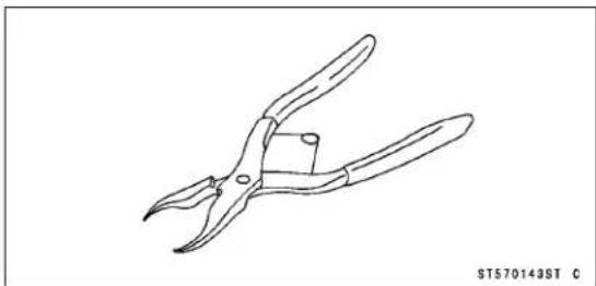
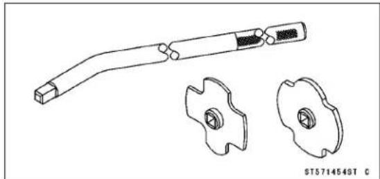
Inside Circlip Pliers: 57001-143
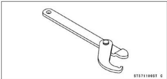
Steering Stem Nut Wrench: 57001-1100
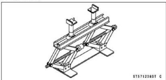
Jack: 57001-1238
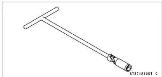
Spark Plug Wrench, Hex 16: 57001-1262
Filler Cap Driver: 57001-1454
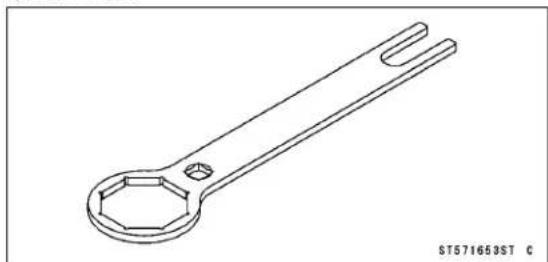
Top Plug Wrench, 49 mm: 57001-1653
2-12 PERIODIC MAINTENANCE
Periodic Maintenance Procedures
Fuel System
Fuel Hose and Connection Inspection
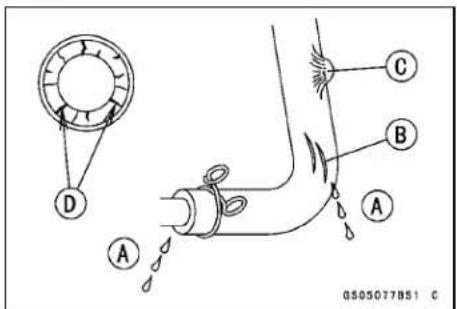
The fuel hoses are designed to be used throughout the motorcycle's life without any maintenance, however, if the motorcycle is not properly handled, the inside the fuel line can cause fuel to leak [A] or the hose to burst.
- Check the fuel hose.
★Replace the fuel hose if any fraying, cracks [B], bulges [C] or ozonic cranks [D] are noticed.
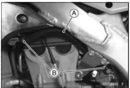
- Check that the hose [A] is securely connected and clamps [B] are tightened correctly.
- When installing, route the hose according to Cable, Wire, and Hose Routing section in the Appendix chapter.
- When installing the fuel hose, avoid sharp bending, kinking, flattening or twisting, and route the fuel hose with a minimum of bending so that the fuel flow will not be obstructed.
★Replace the hose if it has been sharply bent or kinked.
Throttle Grip Free Play Inspection
- Check throttle grip free play [A] by lightly turning the throttle grip [B] back and forth.
★If the free play is improper, adjust the throttle cable.
Throttle Grip Free Play
Standard: 2 \~ 3 mm (0.08 \~ 0.12 in.)
- Check that the throttle grip moves smoothly from full open to close, and the throttle closes quickly and completely in all steering positions by the return spring.
★If the throttle grip does not return properly, check the throttle cable routing, grip free play, and cable damage. Then lubricate the throttle cable.
- Run the engine at the idle speed, and turn the handlebar all the way to the right and left to ensure that the idle speed does not change.
★If the idle speed increase, check the throttle cable free play and the cable routing.
Throttle Grip Free Play Adjustment
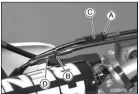
- Loosen the locknuts [A] [B] at the upper end of the throttle cable.
- Screw both throttle cable adjuster [C] [D] to give the throttle grip plenty of play.
- Turn out the decelerator adjuster [C] until there is no play when the throttle grip is completely closed.
- Tighten the locknut [A].
- Turn the accelerator cable adjuster [D] until 2 \~ 3 mm (0.08 \~ 0.12 in.) of throttle grip play is obtained.
- Tighten the locknut [B].

Periodic Maintenance Procedures
WARNING
Operation with an improperly adjusted, incorrectly routed or damaged cables could result in an unsafe riding Condition. Follow the service manual to make sure to correct any of these conditions.
Hot Starter Lever Free Play Inspection
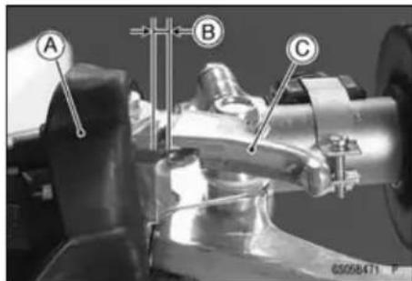
- Slide the clutch lever dust cover [A] back.
- Check the hot starter lever play [B] when pulling the start lever [C] lightly.
Hot Starter Lever Free Play
Standard: 0.5 \~ 1.0 mm (0.02 \~ 0.04 in.)
★If the free play is improper, adjust the hot starter cable.
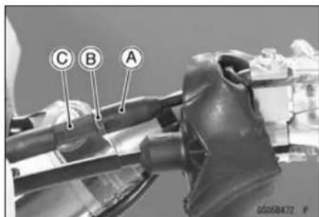
- Slide the adjuster cover [A] back.
- Loosen the locknut [B] and turn the adjuster [C] to obtain the proper lever free play.
- Tighten the locknut securely.
- Check that the hot starter lever moves smoothly from full open to close, and the lever closes quickly and completely in all steering positions by the return spring.
★If the hot starter lever does not return properly, check the hot starter cable routing, free play and cable damage. Then lubricate the hot starter cable.
Idle Speed Inspection
NOTICE
This motorcycle is designed for competition use only. Therefore, the radiator does not incorporate a cooling fan. Prolonged idling of the engine with no airflow through the radiator can cause coolant loss and engine overheating resulting in possible engine damage. Any riding conditions that increase engine temperature will further reduce idling time before coolant loss occurs. These conditions include high ambient temperature, sandy or muddy terrain, or other conditions causing high engine loads at low speeds. Furthermore, warming the engine up excessively before operation, or leaving idling with the hot engine temperature after operation results in the engine overheating, too.
2-14 PERIODIC MAINTENANCE
Periodic Maintenance Procedures
- Start the engine and warm it up thoroughly.
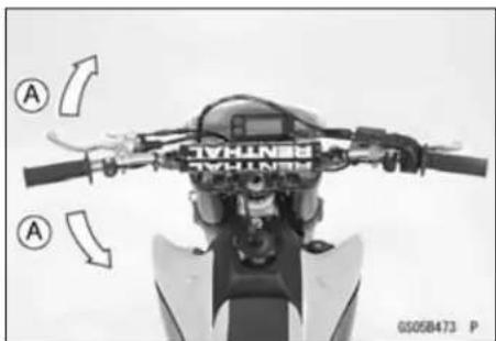
- With the engine idling, turn the handlebar to both sides [A].
★If handlebar movement changes the idle speed, the throttle cable may be improperly adjusted or incorrectly routed, or it may be damaged. Be sure to correct any of these conditions before riding (see Cable, Wire, and Hose Routing section in the Appendix chapter).
WARNING
Operation with an improperly adjusted, incorrectly routed or damaged cables could result in an unsafe riding Condition. Follow the service manual to make sure to correct any of these conditions.
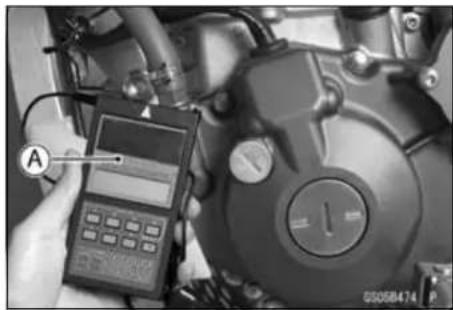
- Check the idle speed, using the engine revolution tester [A] for high accuracy.
★If the idle speed is out of specified range, adjust it.
Idle Speed:
Standard: 1 800 ±50 r/min (rpm)
Idle Speed Adjustment
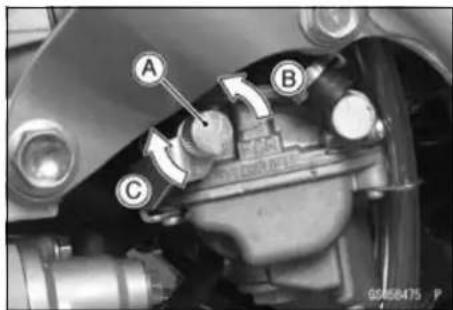
- Start the engine and warm it up thoroughly.
- Turn the idle adjusting screw [A] until the idle speed is correct.
To increase idle speed [B] To decrease idle speed [C] - Open and close the throttle a few times to make sure that the idle speed is within the specified range. Readjust if necessary.
Air Cleaner Element Cleaning and Inspection
NOTE
○ In dusty areas, the element should be cleaned more frequently than recommended interval.
○After riding through rain or on muddy roads, the element should be cleaned immediately.
○ Since repeated cleaning opens the pores of the element, replace it with a new one in accordance with the Periodic Maintenance Chart. Also, if there is a break in the element material or any other damage to the element, replace the element with a new one.
Periodic Maintenance Procedures
WARNING
Gasoline and low-flash point solvents can be flammable and/or explosive and cause severe burns. Clean the element in a well ventilated area, and take care that there is no spark or flame anywhere near the working areas. Do not use gasoline or low-flash point solvents to clean the element.
- Remove:
Front Left Side Cover (see Element Removal in the Fuel System chapter)
Air Cleaner Element (see Element Removal in the Fuel System chapter)
- Stuff a clean, lint-free towel into the carburetor so no dirt is allowed to enter the carburetor.
- Wipe out the inside of the air cleaner housing with a clean damp towel.
NOTICE
Check inside of the intake tract and carburetor for dirt. If dirt is present, clean the intake tract and carburetor thoroughly. You may also need to replace the element and seal the housing and intake tract.
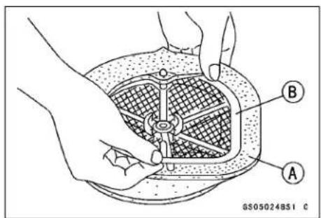
- Separate the element [A] from the frame [B].
- Clean the element [A] in a bath of a high-flash point solvent using a soft bristle brush.
2-16 PERIODIC MAINTENANCE
Periodic Maintenance Procedures
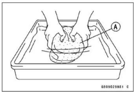
- Squeeze it dry in a clean towel [A]. Do not wring the element or blow it dry; the element can be damaged.
- Check all the parts of the element for visible damage.
★If any of the parts of the element are damaged, replace them.
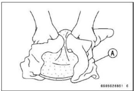
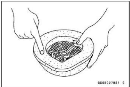
- After cleaning, saturate the element with a high-quality foam-air-filter oil, squeeze out the excess, then wrap it in a clean towel and squeeze it as dry as possible.
○Be careful not to tear the sponge filter.
- Assemble the element.
- Remove the towel from the carburetor.
- Apply grease to all connections and screw holes in the air cleaner housing and intake tract.
- Install the element onto its frame, and coat the element lip and lip seat with a thick layer of all-purpose grease to assure a complete seal.
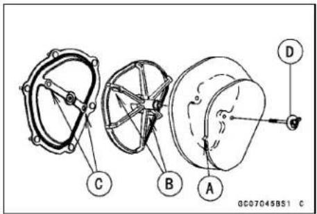
- Install the air cleaner element so that its tab [A] faces left side and its projections [B] align with the holes [C] in the housing.
- Tighten the wing bolt [D]
- Install the seat (see Seat Installation in the Frame chapter).
Fuel Inspection
WARNING
Gasoline is extremely flammable and can be explosive under certain conditions. Always stop the engine and do not smoke. Make sure the area is well ventilated and free from any source of flame or sparks; this includes any appliance with a pilot light.
Periodic Maintenance Procedures
- Turn the fuel tap to the OFF position.
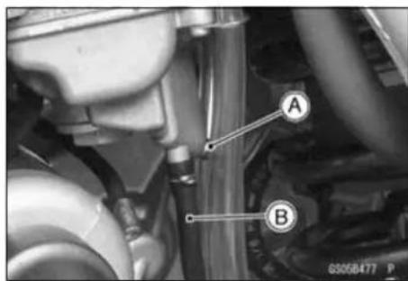
- Place a suitable container beneath the carburetor drain hose [B].
- Loosen the drain plug [A] from the bottom of the float bowl and check for water or dirt in the fuel.
★If any water or dirt comes out, clean the carburetor, fuel filter, fuel tap and fuel tank. - Tighten the drain plug securely.
Fuel Tank, Filter and Tap Cleaning
WARNING
Gasoline and low-flash point solvents can be flammable and/or explosive and cause severe burns. Clean the fuel tank in a well-ventilated area, and take care that there are no sparks or flame anywhere near the working area. Do not use gasoline or low-flash point solvents to clean the fuel tank.
- Remove the fuel tank and drain it (see Fuel Tank Removal in the Fuel System chapter).
- Pour some high-flash point solvent into the fuel tank and shake the tank to remove dirt and fuel deposits.
- Pour the solvent out of the tank.
- Remove the fuel filter from the tank by taking out the bolts.
- Clean the fuel filter screens in a high-flash point solvent. After cleaning, install the fuel filter.
- Pour high-flash point solvent through the tap in all lever positions.
- Dry the tank, filter and tap with compressed air.
• Install the filter in the fuel tank. - Install the tap and fuel tank.
Fuel Tap and Filter Inspection
- Remove the fuel filter from the fuel tank.
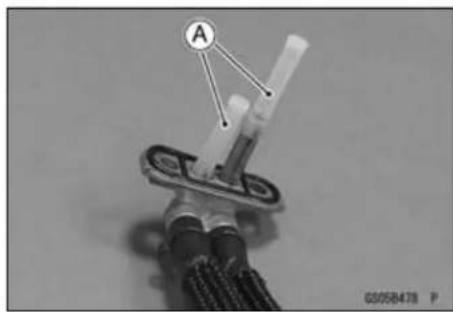
- Check the fuel filter screens [A] for any breaks or deterioration.
★If the fuel filter screen have any breaks or is deteriorated, it may allow dirt to reach the carburetor, causing poor running. Replace the fuel filter. - Remove the fuel tap.
- Check the fuel tap for fuel leaks.
- If the fuel tap leaks, or allows fuel to flow when it is at OFF position, replace the fuel tap.
Cooling System
WARNING
Coolant can be extremely hot and cause severe burns, is toxic and very slippery. Do not remove the radiator cap or attempt to change the coolant when the engine is hot; allow it cool completely. Immediately wipe any spilled coolant from tires, frame, engine or other painted parts. Do not ingest coolant.
2-18 PERIODIC MAINTENANCE
Periodic Maintenance Procedures
Coolant Level Inspection
NOTE
○Check the level when the engine is cold (room or ambient temperature).
- Lean the motorcycle slightly to the left until the radiator cap is level to the ground so that the radiatorcap is located uppermost in order to exhaust the air accumulated in the radiator.
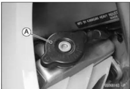
- Remove the radiator cap [A].
NOTE
○ Remove the radiator cap in two steps. First turn the cap counterclockwise to the first stop and wait there for a few seconds. Then push down and turn it further in the same direction and remove the cap.
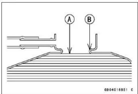
- Check the coolant level. The coolant level [A] should be at the bottom of the filler neck [B].
★If the coolant level is low, add coolant through the filler opening to the bottom of the filler neck. Install the cap.
Recommended coolant:
Permanent type antifreeze (soft water and ethylene glycol plus corrosion and rust inhibitor chemicals for aluminum engines and radiators)
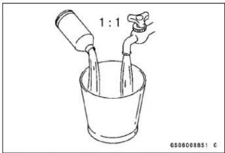
Water and coolant mixture ratio:
1:1 (soft water 50%, Coolant 50%)
Total amount:
1.05 L (1.11 US qt.)
Coolant Deterioration Inspection
- Visually inspect the coolant.
★If whitish cotton-like wafts are observed, aluminum parts in the cooling system are corroded. If the coolant is brown, iron or steel parts are rusting. In either case, flush the cooling system.
★If the coolant gives off an abnormal smell, check for a cooling system leak. It may be caused by exhaust gas leaking into the cooling system.
Periodic Maintenance Procedures
Radiator Hoses and Connections Inspection
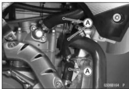
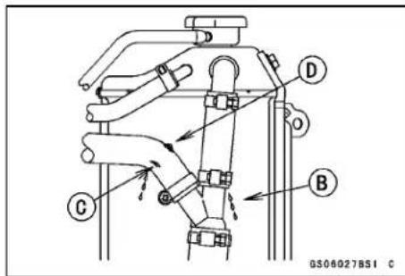
The high pressure inside the radiator hoses and water hoses [A] can cause coolant to leak [B] or the hose to burst if the line is not properly maintained. Visually inspect the hoses for signs of deterioration. Squeeze the hoses. A hose should not be hard and brittle, nor should it be soft or swollen.
★Replace the hose if any fraying, cracks [C] or bulges [D] are noticed.
- Check that the hoses are securely connected and clamps are tightened correctly.
Torque - Radiator Hose Clamp Screws: 3.0 N·m (0.30 kgf·m, 27 in·lb)
Engine Top End
Vacuum Switch Valve Test
U.S.A., California and Canada Models
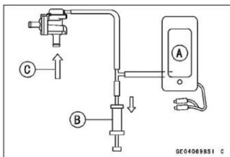
Using the vacuum gauge and a syringe, inspect the vacuum switch operation as follows.
- Remove the vacuum switch valve (see Vacuum Switch Valve Removal in the Engine Top End chapter).
- Connect a vacuum gauge [A] and syringe [B] or fork oil level gauge to the vacuum hoses as shown.
Air Flow [C]
Special Tool - Fork Oil Level Gauge: 57001-1290
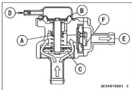
- Gradually raise the vacuum (lower the pressure) applied to the vacuum switch valve, and check the valve operation. When the vacuum is low, the vacuum switch valve should permit air to flow. When the vacuum raises to the level shown below, the valve should stop air flow. When the vacuum is high enough, air cannot flow through the valve.
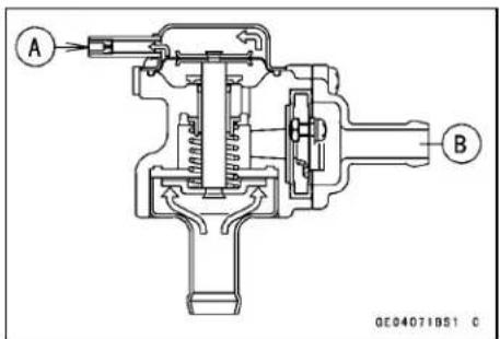
Spring [A]
Diaphragm [B]
Valve [C]
Low Vacuum [D]
Secondary Air Flow [E]
Air Suction Valve [F]
2-20 PERIODIC MAINTENANCE
Periodic Maintenance Procedures
★If the vacuum switch valve does not operate as described, replace it with a new one.
NOTE
○ To check air flow through the vacuum switch valve, just blow through the air cleaner hose.
Vacuum Switch Valve Closing Pressure (open → close) Standard: 48 \~ 59 kPa (360 \~ 440 mmHg)
High Vacuum [A]
Secondary air cannot flow [B].
Valve Clearance Inspection
NOTE
○ Valve clearance must be checked and adjusted when the engine is cold (at room temperature).
- Remove:
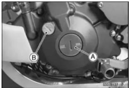
Cylinder Head Cover (see Cylinder Head Cover Removal in the Engine Top End chapter) Crankshaft Cap [A] Timing Inspection Cap [B]
Special Tool - Filler Cap Driver: 57001-1454
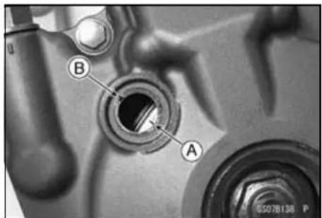
- First, bring the piston to the top-dead-center of its compression stroke to inspect the valve clearance (the position at the end of the compression stroke), when the cam lobe faces outside of the camshaft (see Camshaft Installation in the Engine Top End chapter).
○Place a wrench over the flywheel nut and turn it counterclockwise to align the TDC mark [A] with the center of the groove [B] of the inspection hole.
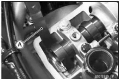
- Using a thickness gauge [A], measure the clearance between each cam lob and valve lifter for all four valves.
○For the purpose of adjusting the valve clearances, record the measured values.
Valve clearance: between cam and valve lifter Standard:
Exhaust 0.20 \~ 0.25 mm (0.0079 \~ 0.0098 in.)
Intake 0.10 \~ 0.15 mm (0.0039 \~ 0.0059 in.)
★If the valve clearance is not within the specified range, adjust it.
Periodic Maintenance Procedures
Valve Clearance Adjustment
- Remove the camshaft caps [A] (see Camshaft Removal in the Engine Top End chapter).
- Remove the camshafts [B] (see Camshaft Removal in the Engine Top End chapter).
- Remove the valve lifters [C] of the applicable valve.
- Remove the shims [D] from the top of the spring retainer.
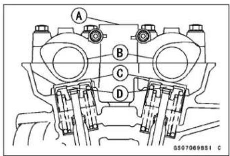
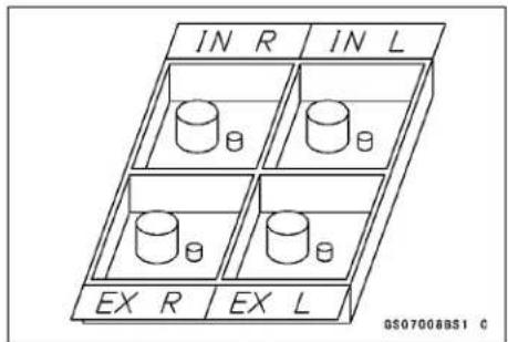
NOTE
○Mark and record the locations of the valve lifters and shims so that they can be reinstalled in their original positions.
- Clean the shim to remove any dust or oil.
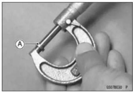
- Measure the thickness of the removed shim [A].
- Select a new shim thickness calculation as follows.
A = (B - C) + D
[A] Replace Shim Thickness
[B] Measured Valve Clearance
[C] Specified Valve Clearance
[D] Present Shim Thickness
Example
(0. 3 1 mm - 0. 1 0 0. 1 5 mm) + 2. 6 0 mm = 2. 8 1 2. 7 6 mm
○Exchange the shims for the 2.775 or 2.800 size shim.
NOTICE
Don't use the shims for another models. This could cause wear of the valve stem end, and valve stem damage.
2-22 PERIODIC MAINTENANCE
Periodic Maintenance Procedures
Adjustment shims
| Thick-ness | P/No. Mark | Thick-ness | P/No. Mark | |||
| 2.00 92 | 025-1870 0 | 2.55 | 92025-1881 | 55 | ||
| 2.05 92 | 025-1871 5 | 2.575 | 92025-1985 | 58 | ||
| 2.10 92 | 025-1872 10 | 2.60 | 92025-1882 | 60 | ||
| 2.15 92 | 025-1873 15 | 2.625 | 92180-1059 | 63 | ||
| 2.20 92 | 025-1874 20 | 2.65 | 92025-1883 | 65 | ||
| 2.25 92 | 025-1875 25 | 2.675 | 92180-1194 | 68 | ||
| 2.30 92 | 025-1876 30 | 2.70 | 92025-1884 | 70 | ||
| 2.35 92 | 025-1877 35 | 2.725 | 92180-1195 | 73 | ||
| 2.375 92 | 180-1058 38 | 2.75 | 92025-1885 | 75 | ||
| 2.40 92 | 025-1878 40 | 2.775 | 92180-1196 | 78 | ||
| 2.425 92 | 025-1982 43 | 2.80 | 92025-1886 | 80 | ||
| 2.45 92 | 025-1879 45 | 2.85 | 92025-1887 | 85 | ||
| 2.475 92 | 025-1983 48 | 2.90 | 92025-1888 | 90 | ||
| 2.50 92 | 025-1880 50 | 2.95 | 92025-1889 | 95 | ||
| 2.525 92 | 025-1984 53 | 3.00 | 92025-1890 | 00 | ||
0507011B51 C
NOTICE
Be sure to remeasure the clearance after selecting a shim. The clearance can be out of the specified range because of the shim tolerance.
○ If there is no valve clearance, use a shim that is a few sizes smaller, and remeasure the valve clearance.
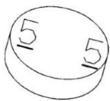
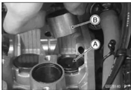
- When installing the shim, face the marked side [A] toward the valve lifter [B]. At this time, apply engine oil to the shim or the valve lifter to keep the shim in place during camshaft installation.
NOTICE
Do not put shim stock under the shim. This may cause the shim to pop out at high rpm, causing extensive engine damage.
Do not grind the shim. This may cause it to fracture, causing extensive engine damage.
- Apply engine oil to the valve lifter surface and install the lifter.
- Install the camshaft (see Camshaft Installation in the Engine Top End chapter).
- Recheck the valve clearance and readjust if necessary.
- Install the cylinder head cover (see Engine Top End chapter), timing inspection cap, and the crankshaft cap.
Special Tool - Filler Cap Driver: 57001-1454
Periodic Maintenance Procedures
Cylinder Head Warp Inspection
- Remove the cylinder head (see Cylinder Head Removal in the Engine Top End chapter).
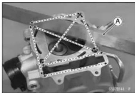
- Lay a straightedge [A] across the lower surface of the head at several different points, and measure warp by inserting a thickness gauge between the straightedge and the head.
★If warp exceeds the service limit, repair the mating surface. Replace the cylinder head if the mating surface is badly damaged.
Cylinder Head Warp
Service Limit: 0.05 mm (0.002 in.)
- Remove the valves (see Valve Removal in the Engine Top End chapter).
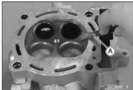
- Scrape the carbon out of the combustion chamber and exhaust port with a scraper [A] or a suitable tool.
- Clean the cylinder head, using high-flash point solvent.
- Blow out any particles which may obstruct the oil passage in the cylinder head using compressed air.
- Install the valves (see Valve Installation in the Engine Top End chapter).
Cylinder Wear Inspection
NOTE
○Measure the cylinder inside diameter when the cylinder is cold (room or ambient temperature).
- Visually Inspect the inside of the cylinder for scratches and abnormal wear.
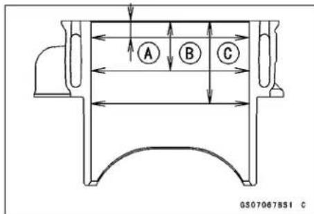
★If the cylinder is damaged or badly worn, replace it with a new one. - Since there is a difference in cylinder wear in different directions, take a side-to-side and a front-to-back measurement shown in the figure.
★If any of the cylinder inside diameter measurements exceeds the service limit, the cylinder must be replaced with a new one since the PLATING cylinder cannot be bored or honed.
[A] 10 mm (0.39 in.)
[B] 30mm(1.2in.)
[C] 50mm(2.0in.)
Cylinder Inside Diameter
Standard: 96.000 \~ 96.012 mm (3.7795 \~ 3.7800 in.)
Service Limit: 96.10 mm (3.783 in.)
2-24 PERIODIC MAINTENANCE
Periodic Maintenance Procedures
Piston/Cylinder Clearance
The piston-to-cylinder clearance is measured whenever a piston or cylinder is replaced with a new one. The standard piston-to-cylinder clearance must be adhered to whenever the cylinder is replaced.
If only a piston is replaced, the clearance may exceed the standard slightly. But it must not be less than the minimum, in order to avoid piston seizure.
The most accurate way to find the piston clearance is by making separate piston and cylinder diameter measurements and then computing the difference between the two values. Measure the piston diameter as just described, and measure the cylinder diameter at the very bottom of the cylinder.
Piston/Cylinder Clearance
Standard: 0.020 \~ 0.042 mm (0.00079 \~ 0.0017 in.)
Piston, Piston Ring and Piston Pin Replacement
- Refer to the Cylinder and Piston Section in Engine Top End chapter.
Spark Arrester Cleaning
This vehicle is equipped with a spark arrester. It must be properly maintained to ensure its efficiency.
NOTICE
The spark arrester must be installed correctly and functioning properly to provide adequate fire protection.
WARNING
Hot exhaust system parts can cause serious burns. The exhaust system becomes very hot soon after the engine is started. To avoid burns, be sure the exhaust system is cold before cleaning the spark arrester.
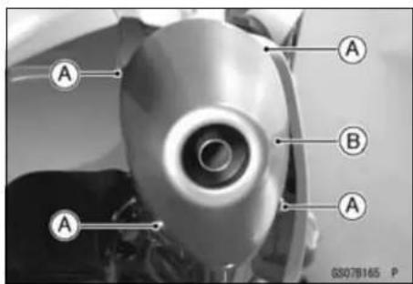
- Remove;
Muffler End Mounting Bolts [A] Muffler End [B]
Periodic Maintenance Procedures
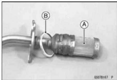
- Remove:
Spark Arrester Mounting Bolts [A] Spark Arrester [B]

- With a wire brush, remove the carbon off the inside of the spark arrester [A] and muffler.
- Inspect the spark arrester.
★If the spark arrester is damaged, replace it with a new one. - Replace the gasket [B] to the new one.
- Install the spark arrester into the rear end of the muffler.
Torque - Spark Arrester Mounting Bolts: 10 N·m (1.0 kgf·m, 89 in·lb)
• Install the muffler end.
Torque - Muffler End Mounting Bolts: 10 N·m (1.0 kgf·m, 89 in·lb)
Engine Right Side
WARNING
The engine and exhaust system get extremely hot during normal operation and can cause serious burns. Never touch the engine or exhaust chamber during clutch adjustment.
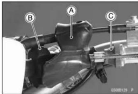
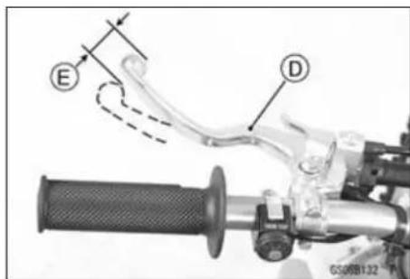
Clutch Lever Free Play Check
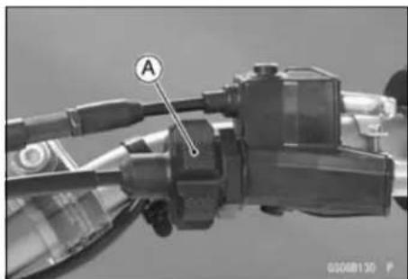
- Slide the clutch lever dust cover [A] and adjusting bolt cover [B] out of place.
- Check that the clutch cable upper end is fully seated in the adjusting bolt [C].
- Check that the clutch lever [D] has 8 \~ 13 mm (0.3 \~ 0.5 in.) of play [E].
★If it does not, adjust the lever play.
2-26 PERIODIC MAINTENANCE
Periodic Maintenance Procedures
Clutch Lever Free Play Adjustment
- Slide the clutch lever dust cover out of place.
- Turn the adjuster [A] so that the clutch lever will have 8 \~ 13 mm (0.3 \~ 0.5 in.) of play.
NOTE
○ Be sure that the outer cable end at the clutch lever is fully seated in the adjusting bolt at the clutch lever, or it could slip into the place later, creating enough cable play to prevent clutch disengagement.
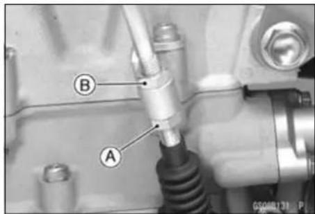
- If it cannot be done, loosen the lower locknut [A] at the lower of the clutch cable, and turn the upper locknut [B] so that clutch lever has 8 \~ 13 mm (0.3 \~ 0.5 in.) of play.
- After the adjustment is made, tighten the locknut, and start the engine and check that the clutch does not slip and that it release properly.
Friction and Steel Plates Inspection
- Removetheclutch plate (Gutcks) Removal in the Engine Right Side chapter).
- Visually inspect the friction and steel plates to see if they show any signs of seizure, or uneven wear.
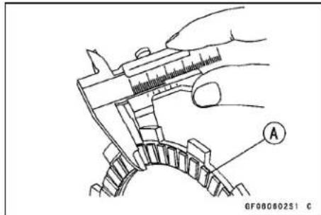
★If any plates show signs of damage, replace the friction plates and steel plates as a set. - Measure the thickness of the friction plates [A] with vernier calipers.
★If they have worn past the service limit, replace them with new ones.
Friction Plate Thickness
Standard: 2.92 \~ 3.08 mm (0.115 \~ 0.121 in.)
Service Limit: 2.6 mm (0.10 in.)
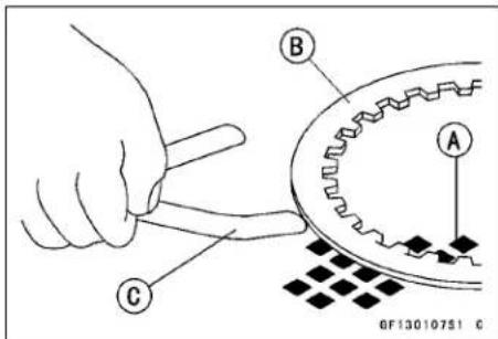
- Place each friction plate or steel plate on a surface plate, and measure the gap between the surface plate [A] and each friction plate or steel plate [B] with a thickness gauge [C]. The gap is the amount of friction or steel plate warp.
★If any plate is warped over the service limit, replace it with a new one.
Friction and Steel Plates Warp
Standard:
Friction Plate 0.15 mm (0.0059 in.) or less
Steel Plate 0.2 mm (0.008 in.) or less
Service Limit:
Friction Plate 0.3 mm (0.01 in.)
Steel Plate 0.3 mm (0.01 in.)
Engine Lubrication System
Engine Oil Change
- Warm up the engine thoroughly so that the oil will pick up any sediment and drain easily. Then stop the engine.
Periodic Maintenance Procedures
- Remove the engine oil drain plugs on the bottom of the engine, and let the oil drain completely.
Drain Plug (Sub) [A]
DrainPlug(Main)[B]
NOTE
○ Hold the motorcycle upright so that the oil may drain completely.
- Replace the gaskets at the drain plugs with a new one.
- After the oil has completely drained out, install the drain plugs with the gaskets, and tighten them.
Torque - Engine Oil Drain Plug (M6)(Sub): 7.0 N·m (0.71 kgf·m, 62 in·lb)
Engine Oil Drain Plug (M10)(Main): 20 N·m (2.0 kgf·m, 15 in·lb)
- Fill the engine with a good quality motor oil specified below.

Recommended Engine
Type Castrol "R4 Superbike" SAE 5W-40 or API SG, SH, SJ, SL or SM with JASO MA, MA1 or MA2
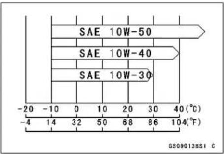
Viscosity SAE 10W-40
Capacity 1.06 L (1.12 US qt.) (when filter is not removed)
1.08 L (1.14 US qt.) (when filter is remove) 1.3 L (1.4 US qt.) (when engine is completely dry)
NOTE
○ Do not add any chemical additive to the oil. Oils fulfilling the above requirements are fully formulated and provide adequate lubrication for both the engine and the clutch.
○ The oil viscosity may need to be changed to accommodate atmospheric conditions in your riding area.
- Check the oil level (see Engine Oil Level Inspection in the Engine Lubrication System chapter).
Oil Filter Change
- Drain:
Engine Oil (see Engine Oil Change)
- Remove:
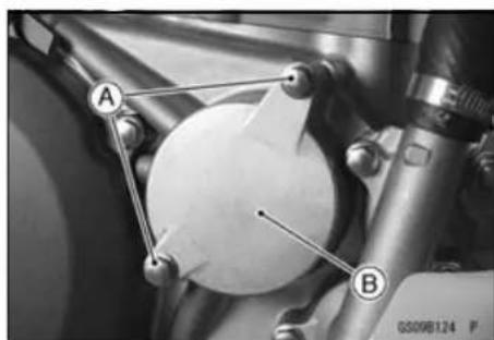
Oil Filter Cover Bolts [A] Oil Filter Cover [B]
2-28 PERIODIC MAINTENANCE
Periodic Maintenance Procedures
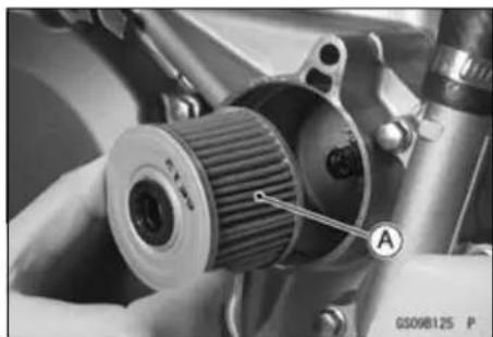
- Remove the Oil Filter [A].
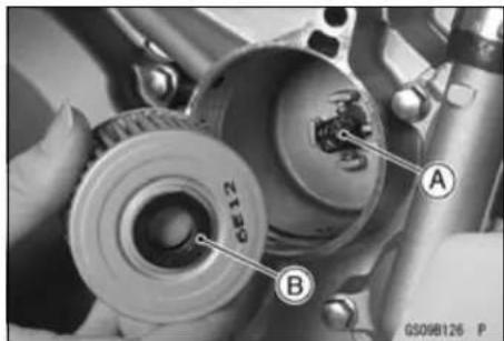
- Install the spring [A] to the right engine cover.
- Apply grease to the grommet [B].
- Be sure to install the filter with the grommet facing outside as shown.
NOTICE
Inside out installation stop oil flow, causing engine seizure.
- Replace the oil filter cover O-rings [A] with a new one.
- Replace the oil filter with new ones.
- Apply grease to the O-rings.
• Install the oil filter cover.
Torque - Oil Filter Cover Bolt: 9.8 N·m (1.0 kgf·m, 87 in·lb)
- Pour in the specified type and amount of oil (see Engine Oil Change).
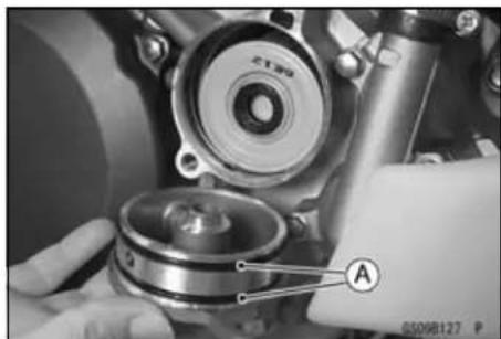
Breather Hose Inspection
- Be certain that the breather hose are routed without being flattened or kinked and is connected correctly.
★If it is not, correct it. - Inspect the breather hoses [A] for damage or sings of deterioration.
- This hose should not be hard and brittle, nor should be soft swollen.
★Replace it if any cracks or swelling is noticed.
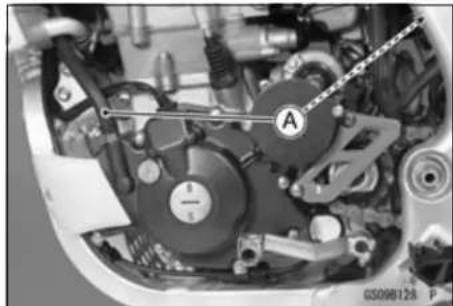
Periodic Maintenance Procedures
Crankshaft/Transmission
Crankshaft Inspection
Connecting Rod Big End Side Clearance
- Remove the cylinder head (see Cylinder Head Removal in the Engine Top End chapter).
- Remove the cylinder (see Cylinder Removal in the Engine Top End chapter).
- Remove the piston (see Piston Removal in the Engine Top End chapter).
- Measure the connecting rod big end side clearance at right side of big end using a thickness gauge [A].
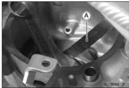
Connecting Rod Big End Side Clearance
Standard: 0.25 \~ 0.35 mm (0.0098 \~ 0.014 in.)
Service Limit: 0.6 mm (0.02 in.)
★If the clearance exceeds the service limit, replace the crankshaft assembly.
- Make sure that the crankshaft rotates smoothly after assembling the engine.
Wheel/Tires
Air Pressure Inspection/Adjustment
- Using tire air pressure gauge [A], measure the tire pressure when the tires are cold.
★Adjust the tire air pressure to suit track conditions and rider preference, but do not stray too far from the recommended pressure.
| Track Condition | Tire Pressure |
| When the track is wet, muddy, sandy or slippery, reduce the tire pressure to increase the tire tread surface on the ground.When the track is pebbly or hard, increase the tire pressure to prevent damage or punctures, through the tires will skid more easily. | 80 kPa (0.8 kgf/cm2, 11 psi)↑↓100 kPa (1.0 kgf/cm2, 14 psi) |
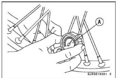
Periodic Maintenance Procedures
Tires Inspection
As the tire tread wears down, the tire becomes more susceptible the puncture and failure.
- Remove any imbedded stones or other foreign particles from the tread.
- Visually inspect the tire for cracks and cuts, replacing the tire in case of bad damage. Swelling or high spots indicate internal damage, requiring tire replacement.
WARNING
Some replacement tires may adversely affect handling and cause an accident resulting in serious injury or death. To ensure proper handling and stability, use only the recommended standard tires for replacement, inflated to the standard pressure.
NOTE
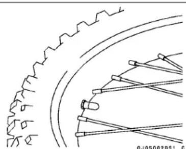
○Check and balance the wheel when a tire is replaced with a new one.
Standard Tire (U.S.A., California, and Canada Models)
Front:
Size: 80/100-21 51M
Make: BRIDGESTONE
Type: D401, Tube
Rear:
Size: 110/100-18 64M
Make: BRIDGESTONE
Type: M402, Tube
Standard Tire (Australia and Europe Models)
Front:
Size: 80/100-21 M/ C 51P
Make: BRIDGESTONE
Type: ED03, Tube
Rear:
Size: 120/90-18 M/C 65P
Make: BRIDGESTONE
Type: ED04, Tube
Spoke Tightness Inspection
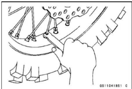
- Check that all the spokes are tightened evenly.
★If spoke tightness is uneven or loose, tighten the spoke nipples evenly.
Torque - Spoke Nipples: 2.2 N·m (0.22 kgf·m, 19 in·lb)
- Check the rim runout.
WARNING
A missing spoke places an additional load on the other spokes, which will eventually cause other spokes to break, creating the potential for an accident resulting in serious injury or death. Immediately replace any broken spoke(s).
Periodic Maintenance Procedures
Rim Runout Inspection
- Place the jack under the frame so that the front/rear wheel off the ground.
Special Tool - Jack: 57001-1238
- Inspect the rim for small cracks, dents, bending, or warping.
★If there is any damage to the rim, it must be replaced.
- Set a dial gauge against the side of the rim, and rotate the rim to measure the axial runout [A]. The difference between the highest and lowest dial readings is the amount of runout.
- Set a dial gauge against the outer circumference of the rim, and rotate the rim to measure radial runout [B]. The difference between the highest and lowest dial readings is the amount of runout.
★If rim runout exceeds the service limit, check the wheel bearings first. Replace them if they are damaged. If the problem is not due to the bearings, correct the rim warp (runout). A certain amount of rim warp can be corrected by recentering the rim. Loosen some spokes and tighten others within the standard torque to change the position of different parts of the rim. If the rim is badly bent, however, it must be replaced.
Rim Runout (with tire installed)
Standard:
Axial TIR 1.0 mm (0.039 in.) or less
Radial TIR 1.0 mm (0.039 in.) or less
Service Limit:
Axial 2 mm (0.08 in.)
Radial 2 mm (0.08 in.)
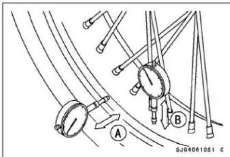
Wheel Bearing Inspection
- Raise the front/rear wheel off the ground.
Special Tool - Jack: 57001-1238
- Spin the wheel lightly, and check for roughness, binding or noise.
★If roughness, binding, abnormal noise is found, replace the hub bearing.
- Turn the handlebar until the handlebar doesn't move to either side.
- The wheel edge is moved to one direction gripping the edge of the wheel by both hands and the play of the wheel bearing is checked.
★If the play is found, replace the bearing.
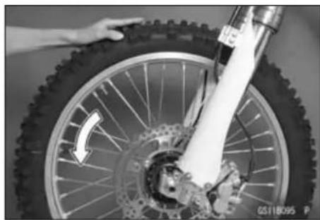
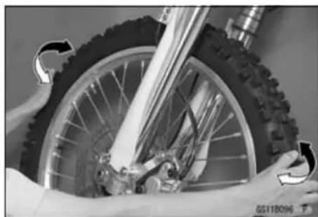
2-32 PERIODIC MAINTENANCE
Periodic Maintenance Procedures
Final Drive
Drive Chain Slack Inspection
- Raise the rear wheel off the ground, rotate the rear wheel to find the place where the chain is tightest (because it wears unevenly).
- Check the wheel alignment (see Wheel Alignment Inspection in the Final Drive chapter), and adjust it if necessary (see Drive Chain Slack Adjustment).
NOTE
○Clean the drive chain if it is dirty, and lubricate it if it appears dry.
- Rotate the rear wheel to find the position where the chain is tightest.
- Measure the space (chain slack) [A] between the chain and the swingarm at the rear of the chain slipper as shown.
★If the drive chain slack exceeds the standard, adjust it.
- Rotate the rear wheel to find the position where the chain is tightest. - Measure the space (chain slack) [A] between the chain and the swingarm at the rear of the chain slipper as shown. ★If the drive chain slack exceeds the standard, adjust it.
Chain Slack
Standard: 52 \~ 58 mm (2.0 \~ 2.3 in.)
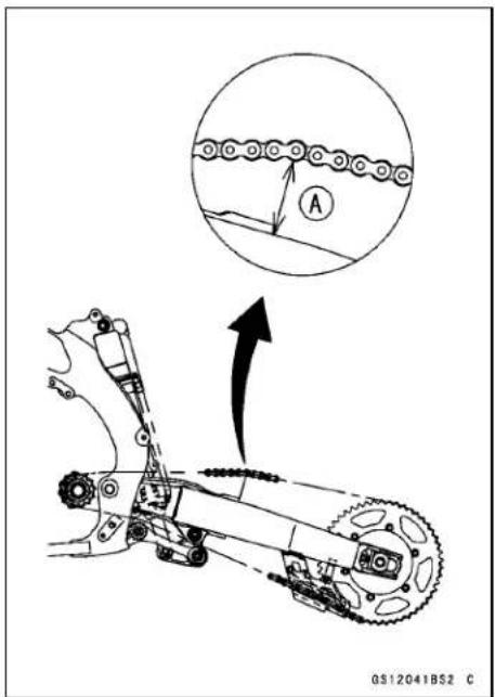
Drive Chain Slack Adjustment
- Loosen the left and right chain adjuster locknuts [A].
- Remove the cotter pin [B] and loosen the axle nut [C].
★If the chain is too tight, back out the left and right chain adjusting bolts [D] evenly, and push the wheel forward until the chain is too loose.
★If the chain is too loose, turn both chain adjusting bolts evenly until the drive chain has the correct amount of slack. To keep the chain and wheel properly aligned, the notch on the left chain adjuster should align with the same swingarm mark [E] as the right chain adjuster notch [F].
★Check the wheel alignment.
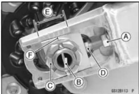
WARNING
Misalignment of the wheel will result in abnormal wear and may result in an unsafe riding condition. Be sure the wheel is properly aligned.
- Tighten both chain adjuster locknuts securely.
- Tighten the axle nut.
Torque - Rear Axle Nut: 110 N·m (11.2 kgf·m, 81.1 ft·lb) - Rotate the wheel, measure the chain slack again at the tightest position, and readjust if necessary.
- Install a new cotter pin [A] through the axle nut and axle, and spread its ends.
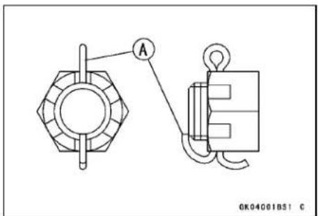
Periodic Maintenance Procedures
NOTE
○ When inserting the cotter pin, if the slots in the nut do not align with the cotter pin hole in the axle shaft, tighten the nut clockwise [A] up to next alignment.
○ It should be within 30 degree.
○ Loosen one and tighten again when the slot goes past the nearest hole.
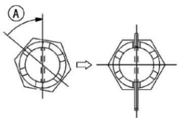
GJ04034BS1 C
WARNING
A loose axle nut can lead to an accident resulting in serious injury or death. Tighten the axle nut to the proper torque and install a new cotter pin.
- Check the rear brake.
NOTE
○ In wet and muddy conditions, mud sticks to the chain and sprockets resulting in an overly tight chain, and the chain may break. To prevent this, adjust the chain to 58 \~68 mm (2.28 \~2.68 in.) of slack whenever necessary.
Drive Chain Wear Inspection
- Rotate the rear wheel to inspect the drive chain for damaged rollers, and loose pins and links.
★If there is any irregularity, replace the drive chain.
★Lubricate the drive chain if it appears dry.
[A] Bushing
[B] Roller
[C] Pin
[D] Pin Link
[E] Roller Link
[F] O-ring
- Stretch the chain taut by hanging a 98 N (10 kgf, 20 lb) weight [A] on the chain.
- Measure the length of 20 links [B] on the straight part [C] of the chain from the pin center of the 1st pin to the pin center of the 21st pin. Since the chain may wear unevenly, take measurements at several places.
Chain 20-link Length
Standard: 317.5 \~ 318.2 mm (12.50 \~ 12.53 in.)
Service Limit: 323 mm (12.7 in.)
★If any measurements exceed the service limit, replace the chain. Also, replace the front and rear sprockets when the drive chain is replaced.
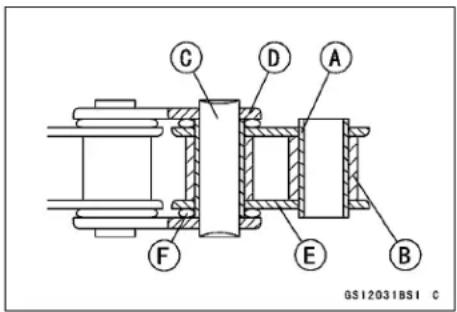
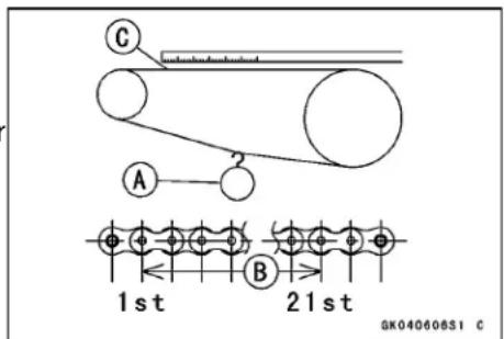
2-34 PERIODIC MAINTENANCE
Periodic Maintenance Procedures
WARNING
A chain that breaks or jumps off the sprockets could snag on the engine sprocket or lock the rear wheel, severely damaging the motorcycle and causing it to go out of control. Inspect the chain for damage and proper adjustment before each ride. If chain wear exceeds the service limit, replace it with the standard chain.
Standard Chain
Make: DAIDO
Type: D.I.D 520MXV
Link: 114 Links
Drive Chain Lubrication
The chain should be lubricated with a lubricant which will both prevent the exterior from rusting and also absorb shock and reduce friction in the interior of the chain.
★If the chain is especially dirty, it should be washed in diesel oil or kerosene, and afterward soaked in a heavy oil. Shake the chain while it is in the oil so that oil will penetrate to the inside of each roller.
- An effective, good quality lubricant specially formulated for chains is best for regular chain lubrication.
- If a special lubricant is not available, a heavy oil such as SAE90 is preferred to a lighter oil because it will stay on the chain longer and provide better lubrication.
- Apply oil to the sides of the rollers so that oil will penetrate to the rollers and bushings.
● Wipe off any excess oil.
Oil applied area [A]
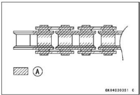
Sprocket Wear Inspection
- Visually inspect the front and rear sprocket teeth for wear and damage.
★If they are worn as illustrated or damaged, replace the sprocket.
[A] Worn Tooth (Engine Sprocket)
[B] Worn Tooth (Rear Sprocket)
[C] Direction of Rotation
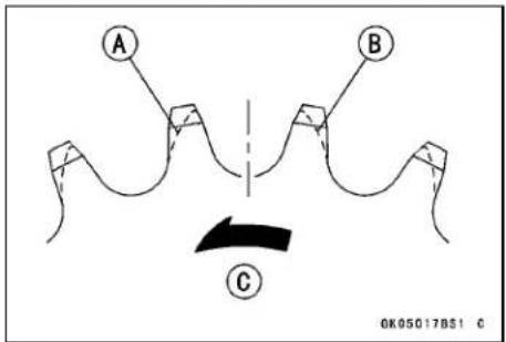
NOTE
○If a sprocket requires replacement, the chain is probably worn also. When replacing a sprocket, inspect the chain.
Periodic Maintenance Procedures
Rear Sprocket Warp Inspection
- Using the jack, raise the rear wheel off the ground. Special Tool - Jack: 57001-1238
- Set a dial gauge [A] against the rear sprocket [B] near the teeth as shown and rotate [C] the rear wheel to measure the sprocket runout (warp). The difference between the highest and lowest dial gauge readings is the amount of runout (warp).
★If the runout exceeds the service limit, replace the rear sprocket.
Rear Sprocket Warp
Standard: 0.4 mm (0.016 in.) or less
Service Limit: 0.5 mm (0.02 in.)
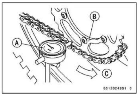
Brakes
Brake Lever and Pedal Position Adjustment
WARNING
An improperly adjusted brake could drag and cause the brake to overheat, damaging the brake assembly and possibly locking the rear wheel, resulting in loss of control. Always maintain the proper brake adjustment.
- Adjust the front brake lever [A] to suit you.
- Slide the brake lever dust cover [B] out of place.
- Loosen the adjuster locknut [C] and turn the adjuster [D] to either side.
- After adjustment, tighten the locknut.
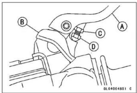
NOTE
○Usually it is not necessary to adjust the pedal position, but always adjust it when the master cylinder is disassembled or pedal position is incorrect.
● Measure the length indicated in the figure.
Length [A]
Standard: 68.5 ±1 mm (3.09 ±0.04 in.)
★If it is not specified length, the brake pedal may be deformed or incorrectly installed.
★If it is not within the specified length, adjust the push rod in the master cylinder as follows.
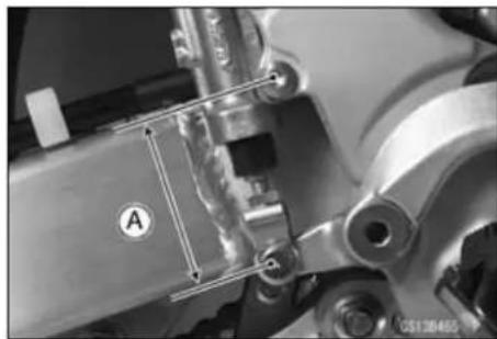
2-36 PERIODIC MAINTENANCE
Periodic Maintenance Procedures
○Loosen the push rod locknut [A].
○Replace the cotter pin with a new one.
○Remove:
Cotter Pin [B]
Washer
Joint Pin [C]
○Turn the bracket [D] to obtain the specified length.
○Tighten the locknut.
Torque - Rear Master Cylinder Push Rod Locknut: 17 N·m (1.7 kgf·m, 13 ft·lb)
Brake Fluid Level Inspection
- Check the brake fluid level in the front or rear brake reservoir [A].
NOTE
○Hold the reservoir horizontal when checking brake fluid level.
- The front or rear reservoir must be kept above the lower level line [B].
○If the fluid level in front or rear reservoir is lower than the lower level line, fill the reservoir to the upper level line. Inside the reservoir is stopped end showing the upper level line [C].
Torque - Reservoir Cap Screws: 1.5 N·m (0.15 kgf·m, 13 in·lb)
WARNING
Mixing brands and types of brake fluid can reduce the brake system's effectiveness and cause an accident resulting in injury or death. Do not mix two brands of brake fluid. Change the brake fluid in the brake line completely if the brake fluid must be refilled but the type and brand of the brake fluid that is already in the reservoir are unidentified.
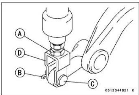
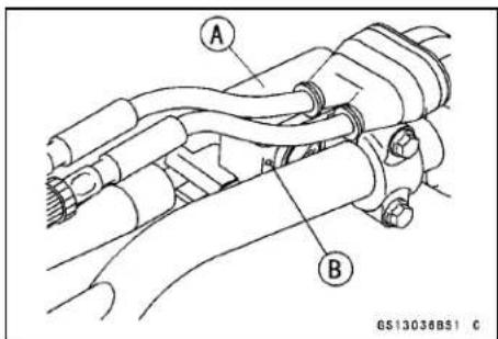
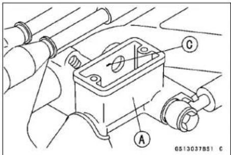
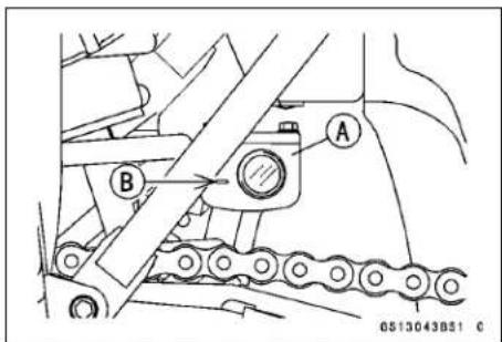
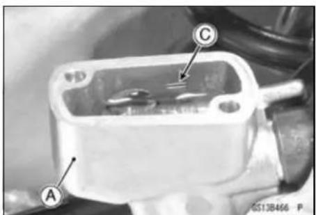
Periodic Maintenance Procedures
Brake Fluid Change
In accordance with the Periodic Maintenance Chart, change the brake fluid. The brake fluid should also be changed if it becomes contaminated with dirt or water. Furthermore, the brake fluid should be changed to bleed the air quickly and completely whenever the brake line parts are removed.
WARNING
When working with the disc brake, observe the precautions listed below.
- Never reuse old brake fluid.
- Do not use fluid from a container that has been left unsealed or that has been open for a long time.
- Do not mix two types and brands of fluid for use in the brake. This lowers the brake fluid boiling point and could cause the brake to be ineffective. It may also cause the rubber brake parts to deteriorate.
- Don't leave the reservoir cap off for any length of time to avoid moisture contamination of the fluid.
- Don't change the fluid in the rain or when a strong wind is blowing.
- Except for the disc pads and disc, use only disc brake fluid, isopropyl alcohol, or ethyl alcohol for cleaning of the brake parts. Do not use any other fluid for cleaning these parts. Gasoline, engine oil, or any other petroleum distillate will cause deterioration of the rubber parts. Oil spilled on any part will be difficult to wash off completely and will eventually deteriorate the rubber used in the disc brake.
- When handling the disc pads or disc, be careful that no disc brake fluid or any oil gets on them. Clean off any fluid or oil that inadvertently gets on the pads or disc with a high-flash point solvent. Do not use one which will leave an oily residue. Replace the pads with new ones if they cannot be cleaned satisfactorily.
- Brake fluid quickly ruins painted surfaces; any spilled fluid should be completely wiped up immediately.
- If any of the brake line fittings or the bleed valve is opened at any time, the AIR MUST BE BLED FROM THE BRAKE LINE.
Recommended Disc Brake Fluid
Type:
Front DOT3 or DOT4
Rear DOT4
2-38 PERIODIC MAINTENANCE
Periodic Maintenance Procedures
NOTE
○The procedure to change the front brake fluid. Changing the rear brake fluid is the same as for the front brake.
- Level the brake fluid reservoir.
- Remove the screws [A], reservoir cap [B] and diaphragm [C].
- Remove the rubber cap [A] on the bleed valve [B].
- Attach a clear plastic hose [A] to the bleed valve on the caliper, and run the other end of the hose into a container [B].
- Change the brake fluid as follows:
- Repeat this operation until fresh brake fluid comes out from the plastic hose or the color of the fluid changes.
-
Open the bleed valve [A]
-
Apply the brake and hold it [B]
-
Close the bleed valve [C]
-
Release the brake [D]
○Fill the reservoir with fresh specified brake fluid.
NOTE
The fluid level must be checked often during the changing operation and replenished with fresh brake fluid. If the fluid in the reservoir runs out any time during the changing operation, the brakes will need to be bled since air will have entered the brake line.
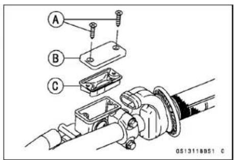
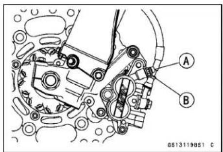
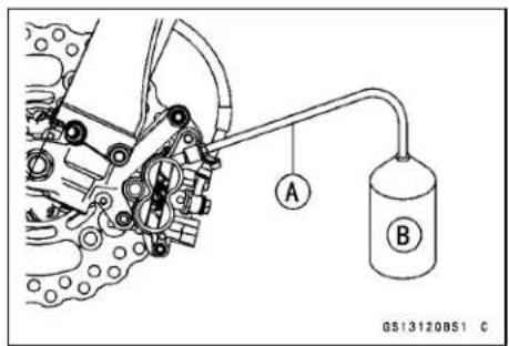
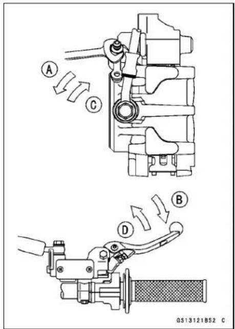
Periodic Maintenance Procedures
- Remove the clear plastic hose.
- Tighten the bleed valves, and install the rubber caps.
Torque - Caliper Bleed Valve: 7.8 N·m (0.80 kgf·m, 69 in·lb)
Brake Reservoir Cap Screws: 1.5 N·m (0.15 kgf·m, 13 in·lb)
- After changing the fluid, check the brake for good braking power, no brake drag, and no fluid leakage.
★If necessary, bleed the air from the lines (see Bleeding the Brake Line in the Brakes chapter).
WARNING
Mixing brands and types of brake fluid can reduce the brake system's effectiveness and cause an accident resulting in injury or death. Do not mix two brands of brake fluid. Change the brake fluid in the brake line completely if the brake fluid must be refilled but the type and brand of the brake fluid that is already in the reservoir are unidentified.
Brake Pad Wear Inspection
- Remove the brake pad (see Brake Pad Removal in Brakes chapter).
- Check the lining thickness and condition of the pads in each caliper.
★If either pad is damaged, replace both pads in the caliper as a set.
★If the lining thickness [A] of either pad is less than the service limit [B], replace both pads in the caliper as a set.
Lining Thickness
Standard:
Front 3.8 mm (0.15 in.)
Rear 6.4 mm (0.25 in.)
Service Limit:
Front 1 mm (0.04 in.)
Rear 1 mm (0.04 in.)

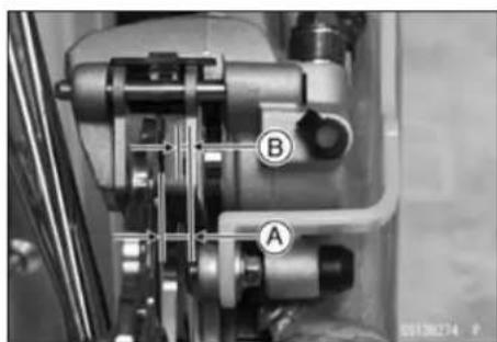
Brake Master Cylinder Cup and Dust Seal Replacement
- Remove the front master cylinder (see Front Master Cylinder Removal in the Brakes chapter).
- Remove the reservoir cap and diaphragm, and pour the brake fluid into a container.
- Unscrew the locknut and pivot bolt, and remove the brake lever.
- Pull the dust cover [A] out of place, and remove the circlip [B].
Special Tool - Inside Circlip Pliers: 57001-143
- Remove the washer [C].
- Pull out the piston [D], secondary cup [E], primary cup [F], and return spring [G].
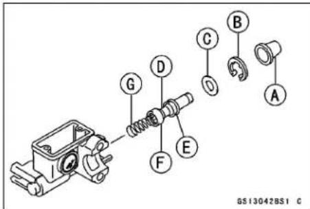
Periodic Maintenance Procedures
NOTICE
Do not remove the secondary cup from the piston since removal will damage it.
- Remove the rear master cylinder (see Rear Master Cylinder Removal in the Brakes chapter).
NOTE
- Do not remove the push rod clevis for master cylinder disassembly since removal requires brake pedal position adjustment.
- Remove the reservoir cap and diaphragm, and pour the brake fluid into a container.
- Slide the dust cover [A] on the push rod [B] out of place, and remove the circlip [C].
Special Tool - Inside Circlip Pliers: 57001-143
- Pull out the push rod with the piston stop [D].
- Take off the piston [E], secondary cup [F], primary cup [G], and return spring [H].
NOTICE
Do not remove the secondary cup from the piston since removal will damage it.
- Before assembly, clean all parts including the master cylinder with brake fluid or alcohol.
NOTICE
Except for the disc pads and disc, use only disc brake fluid, isopropyl alcohol, or ethyl alcohol for cleaning of the brake parts. Do not use any other fluid for cleaning of these parts. Gasoline, engine oil, or any other petroleum distillate will cause deterioration of the rubber parts. Oil spilled on any part will be difficult to wash off completely, and will eventually deteriorate the rubber used in the disc brake.
- Apply brake fluid to the removed parts and to the inner wall of the cylinder.
- Take care not to scratch the piston or the inner wall of the cylinder.
-
Apply silicone grease (ex. PBC grease).
Brake Lever Pivot Bolt Brake Lever Pivot Contact Push Rod Contact (Rear) Dust Covers -
Tighten:
Torque - Brake Lever Pivot Bolt: 5.9 N·m (0.60 kgf·m, 52 in·lb)
Brake Lever Pivot Bolt Locknut: 5.9 N·m (0.60 kgf·m, 52 in·lb)
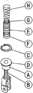
GL07057BS2 C
Periodic Maintenance Procedures
Caliper Piston Seal and Dust Seal Replacement
- Loosen the brake pad pin [A] and banjo bolt [B], and tighten them loosely.
- Remove:
Front Caliper Mounting Bolts [C]
Banjo Bolt
Brake Hose [E]
Front Caliper [D] (see Front Caliper Removal in the Brakes chapter)
Brake Pads (see Brake Pad Removal in the Brakes chapter)
- Separate the caliper holder [A] from the caliper [B] and remove the anti-rattle spring.
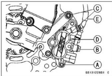
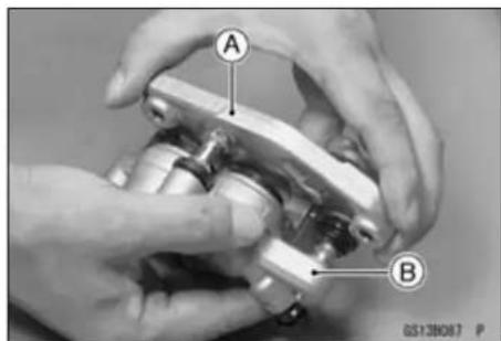
- Using compressed air, remove the pistons. One way to remove the pistons is as follows.
○Cover the caliper opening with a clean, heavy cloth [A].
○Remove the pistons by lightly applying compressed air [B] to the hose joint opening.
WARNING
The piston in the brake caliper can crush hands and fingers. Never place your hand or fingers in front of the piston.
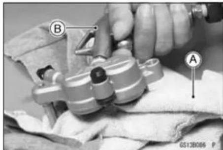
○Pull out the piston [A] by hand.
- Remove the dust seals [B] and fluid seals [C].
NOTE
○ If compressed air is not available, do as follows for both calipers coincidentally, with the brake hose connected to the caliper.
○Prepare a contai ner for brake fluid, and perform the work above it.
○ Remove the spring and pads (see Brake Pad Removal in the Brakes chapter).
○Pump the brake lever until the pistons come out of the cylinders, and then disassembly the caliper.
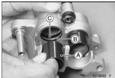
2-42 PERIODIC MAINTENANCE
Periodic Maintenance Procedures
- Remove the rear caliper (see Caliper Removal in the Brakes chapter).
- Remove the pads (see Brake Pad Removal in the Brakes chapter).
- Separate the caliper holder [B] from the caliper [A].
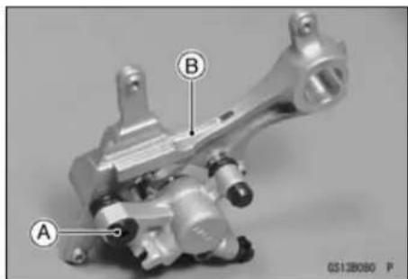
- Using compressed air, remove the piston.
○Cover the caliper opening with a clean, heavy cloth [A].
○Remove the piston by lightly applying compressed air [B] to where the brake line fits into the caliper.
WARNING
The piston in the brake caliper can crush hands and fingers. Never place your hand or fingers in front of the piston.
- Pull out the piston [A] by hand.
- Remove the dust seal [B] and fluid seal [C].
- Clean the caliper parts except for the pads.
NOTICE
For cleaning of the parts, use only disc brake fluid, isopropyl alcohol, or ethyl alcohol.
- The bleed valve was removed, install the bleed valve and rubber cap.
Torque - Bleed Valve: 7.8 N·m (0.80 kgf·m, 69 in·lb)
- Replace the fluid seal(s) [A] with new ones.
○Apply brake fluid to the fluid seal(s), and install them into the cylinders by hand. - Replace the dust seal(s) [B] with new ones.
○Apply brake fluid to the dust seal(s), and install them into the cylinder by hand. - Apply brake fluid to the outside of the pistons [C], and push them into each cylinder by hand.
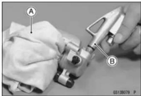
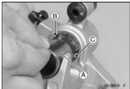
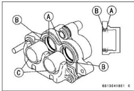
- Install the anti-rattle spring [A] in the caliper as shown.
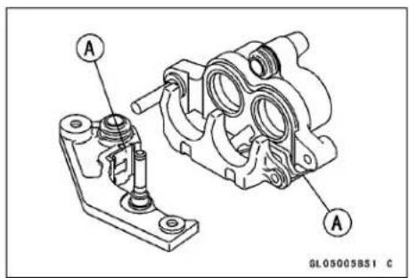
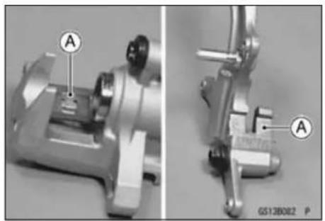
- Replace the shaft rubber friction boot [A] and dust boot [B] if they are damaged.
- Apply a thin coat of PBC (Poly Butyl Cuprysil) grease to the caliper holder shafts [C] and holder holes (PBC is a special high temperature, water-resistance grease).
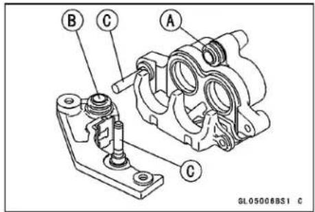
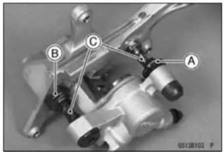
• Install the pads (see Brake Pad Installation in the Brakes chapter).
- Install the caliper (see Caliper Installation in the Brakes chapter).
- Wipe up any spilled brake fluid on the caliper with wet cloth.
2-44 PERIODIC MAINTENANCE
Periodic Maintenance Procedures
Brake Hose and Connection Check
- Inspect the brake hose and fittings for deterioration, cracks and signs of leakage.
The high pressure inside the brake line can cause fluid to leak [A] or the hose to burst if the line is not properly maintained. Bend and twist the rubber hose while examining it.
★Replace the hose if any cracks [B] or bulges [C] are noticed.
★Tighten any loose fittings.
Brake Hose Replacement
NOTICE
Brake fluid quickly ruins painted surfaces; any spilled fluid should be completely washed away immediately.
- When removing the brake hose, take care not to spill the brake fluid on the painted or plastic parts.
- When removing the brake hose temporarily secure the end of the brake hose to some high place to keep fluid loss to a minimum.
- Immediately wash away any brake fluid that spills.
- Remove each banjo bolts [A] and washers [B].
- Replace the washers with new ones.
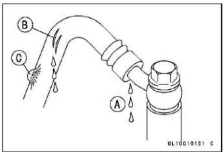
For Front Brake
- Remove: Bolts [A] Brake Hose Clamps [B]
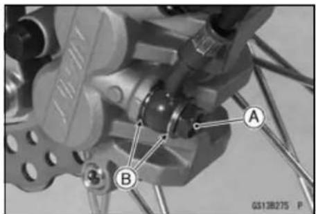
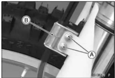
Periodic Maintenance Procedures
For Rear Brake
- Remove: Master Cylinder [A] Hose Clamps [B] Caliper Cover [C]

- When installing the hoses, avoid sharp bending, kinking, flattening or twisting, and route the hoses according to Cable, Wire, and Hose Routing section in the Appendix chapter.
- Tighten the banjo bolts on the hose fittings. Torque - Brake Hose Banjo Bolts: 25 N·m (2.5 kgf·m, 18 ft·lb)
- Fill the brake line after installing the brake hose (see Brake Fluid Changing).
Suspension
Front Fork Inspection
- Holding the brake lever, pump the front fork back and forth manually to check for smooth operation.
- Visually inspect the front fork for oil leakage, scoring or scratches on the outer surface of the inner tube [A].
★If necessary, repair any damage. - Nick or rust damage can sometimes be repaired by using a wet-stone to remove sharp edges or raised areas which cause seal damage.
★If the damage is not repairable, replace the inner tube. Since damage to the inner tube damages the oil seal, replace the oil seal whenever the inner tube is repaired or replaced. - If the fork is not smooth, confirm the cause.
NOTICE
If the inner tube is badly bent or creased, replace it. Excessive bending, followed by subsequent straightening, can weaken the inner tube.
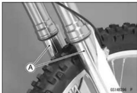
Front Fork Oil Change (each fork leg)
- Loosen the front fork upper clamp bolts [A].
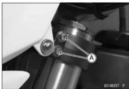
2-46 PERIODIC MAINTENANCE
Periodic Maintenance Procedures
- Loosen the fork top plug [A].
Special Tool - Top Plug Wrench, 49 mm [B]: 57001-1653 - Remove:
Front Wheel (see Front Wheel Removal in the Wheels/Tires chapter)
Front Brake Caliper (see Caliper Removal in the Brakes chapter)
Brake Hose Clamps (see Brake Hose Replacement)
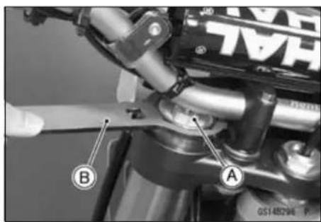
- Loosen the front fork lower clamp bolts [A].
- Remove the front fork.
With a twisting motion, work the fork leg [B] down and out.
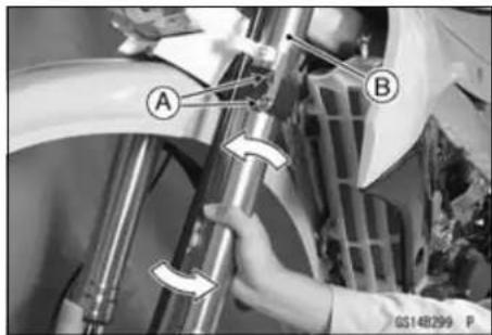
NOTE
○ Set rebound and compression damping setting to the softest settings before disassembling to prevent the needle of adjusters from damaging. Record the setting before turning the adjuster.
- Thoroughly clean the fork before disassembly.
NOTICE
Be careful not scratch the inner tube and not to damage the dust seal.
Avoid scratching or damaging the inner tube or the dust seal. Use a mild detergent and sponge out dirt with plenty of water.
- Using the top plug wrench [A], remove [B] (subtank) from the outer tube and slowly slide down the outer tube [C].
Special Tool - Top Plug Wrench, 49 mm: 57001-1653
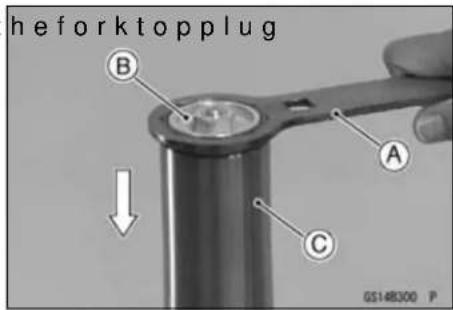
Periodic Maintenance Procedures
- Place a drain pan under the front fork and drain fork oil [A].
NOTE
○ Pump the fork tube several times to discharge the fork oil.
- Raise the outer tube and temporarily install the fork top plug [A] (subtank) to the outer tube [B] with the top plug wrench [C].
Special Tool - Top Plug Wrench, 49 mm: 57001-1653
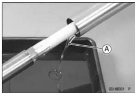
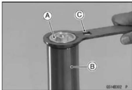
- Hold the axle holder [A] with a vise.
○Protect the axle holder with a rag when using a vise. - Remove the cap.
- Loosen the adjuster assembly [B] completely.
WARNING
Clamping the axle holder part too tight can damage it which will affect riding stability. Do not clamp the axle holder part too tight.
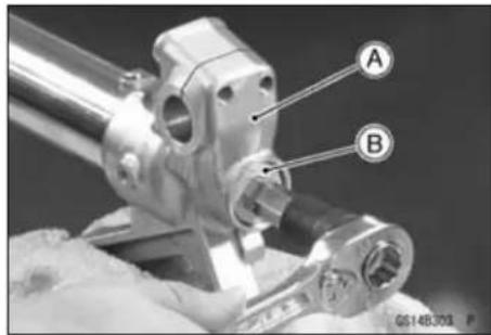
- Compress the outer tube by hands and install the top plug wrench [A] between the axle holder bottom [B] and locknut [C].
Special Tool - Top Plug Wrench, 49 mm: 57001-1653
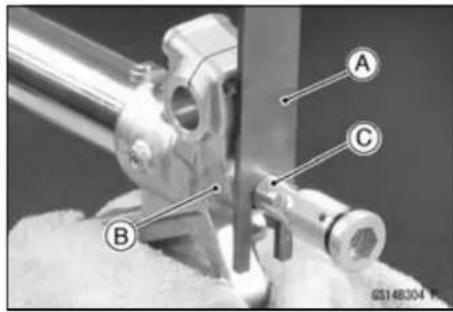
WARNING
The fork spring applies pressure to the adjuster assembly and can eject the special tool with substantial force if the tool is not properly and securely placed. Be sure the tool is fully in place as shown in the photo, and keep fingers away to avoid getting them pinched between the tool, adjuster assembly and axle holder.
2-48 PERIODIC MAINTENANCE
Periodic Maintenance Procedures
- Hold the locknut [A] with a wrench [B] and remove the adjuster assembly [C].
- Remove the push rod [A].
- With the outer tube compressed by hands, remove the topplugwrench[A].
NOTICE
Removing the locknut and pushin g the piston rod thread into the cylinder unit will damage the oil seal. Do not remove the locknut from the piston rod.
- Remove the fork leg from the vise.
- Loosen the fork top plug (subtank) [A] with the top plug wrench [B].
Special Tool - Top Plug Wrench, 49 mm: 57001-1653
- Remove: Cylinder Unit [A] Spacer [B] Fork Spring [C]
NOTICE
Disassembling the cylinder unit can lead to trouble. Do not disassemble the cylinder unit.
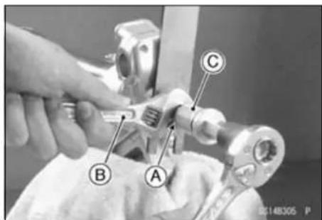
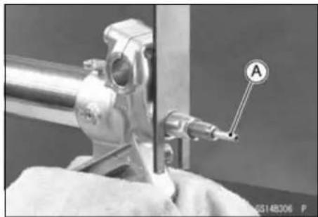
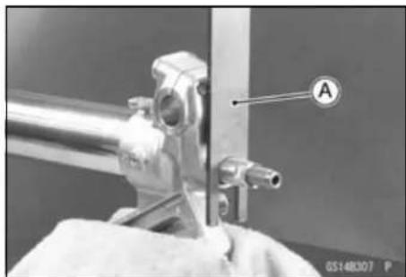
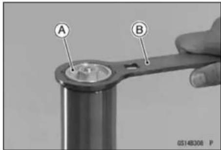
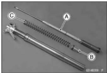
Periodic Maintenance Procedures
- Holding the top plug wrench [A] with a vise, loosen the base valve assembly [B] on the subtank [C].
Special Tool - Top Plug Wrench, 49 mm: 57001-1653
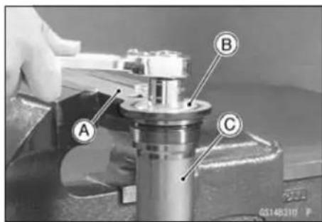
- Remove the base valve assembly [A] from the subtank [B].
NOTE
○ Slowly compress the piston rod until it stops so that the base valve assembly can be removed easily.
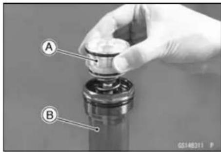
NOTICE
Disassembling the base valve assembly can lead to trouble.
Do not disassemble the base valve assembly.
- Drain the fork oil [A] from the cylinder unit [B] by pumping the piston rod several times.
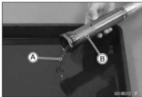
- Hold the front fork inverted position for more than 20 minutes to allow the fork oil to fully drain.
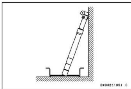
- Clean the threads [A] of subtank and base valve assembly.
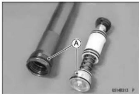
2-50 PERIODIC MAINTENANCE
Periodic Maintenance Procedures
- With the piston rod in fully compressed position, pour the specified amount of fork oil [A].
Recommended Oil: KHL15-10 (KAYABA01) or equivalent
Recommended Quantity: 189 ml (6.4 US oz.)
NOTE
○ Plug the two oil holes on the subtank [B] with fingers.
- Pump [A] the piston rod [B] slowly several times to expel air.
- Replace the O-rings [A] on the base valve assembly with new ones.
- Apply specified fork oil to the O-rings [A] [B] and bushings [C] on the base valve assembly.
- With the piston rod held immorable in fully compressed position [A], gently install the base valve assembly [B] to the subtank.
- Screw in the base valve assembly in the subtank when the piston rod extends.
NOTE
○ When it is hard to screw in the base valve assembly, pull down the piston rod a little.
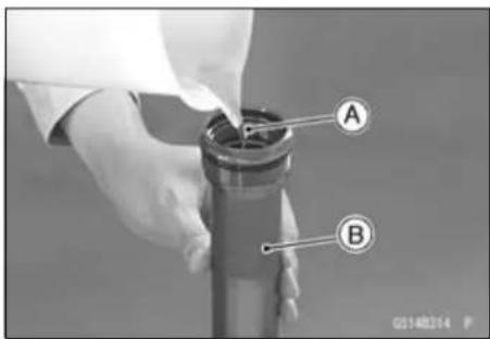
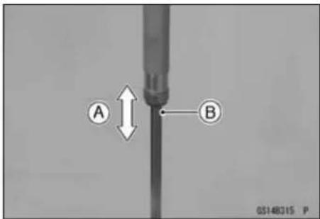
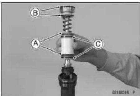
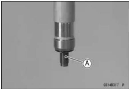
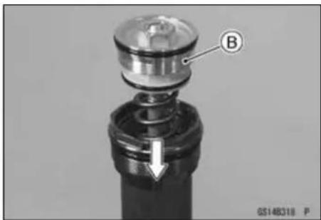
Periodic Maintenance Procedures
● Holding the top plug wrench [A] with avise. Special Tool - Top Plug Wrench, 49 mm: 57001-1653
- Holding the subtank [B] with the top plug wrench, torque the base valve assembly [C].
Torque - Base Valve Assembly: 28 N·m (2.9 kgf·m, 21 ft·lb)
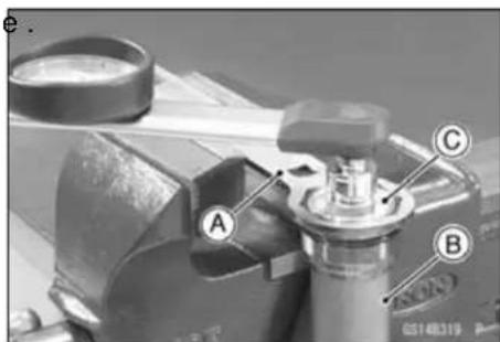
- Protect the piston rod end [A] with a rag [B] to prevent fork damage.
- Discharge the extra oil off the cylinder unit by pumping [C] the piston rod to full stroke.
NOTICE
Be careful not to bend or damage the piston rod when the piston rod is stroked. Service carefully because oil flies out from the oil hole of the cylinder unit.
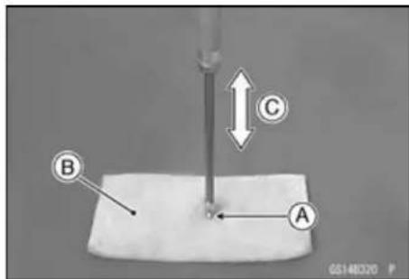
NOTE
○ Set the compression damper setting to the softest.
○ Check the piston rod sliding surface for damage.
○Apply fork oil to the piston rod sliding surface.
- Drain the extra oil from the subtank oil hole [A].
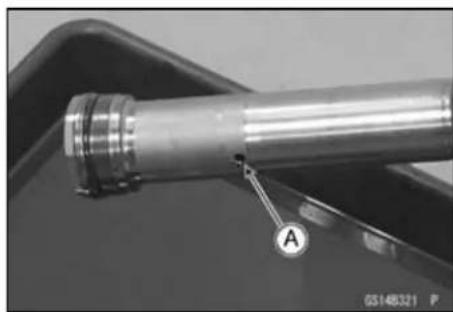
- With the cylinder unit in horizontal position, move [A] the piston rod [B] by hand to inspect it if operating smoothly. - If the piston rod is not extend, remove the base valve assembly and perform the air bleeding (pour the specified amount fork oil and discharge an excess of oil).

2-52 PERIODIC MAINTENANCE
Periodic Maintenance Procedures
- Completely wipe of the fork oil from the spring [A], spacer [B] and cylinder unit [C].
- Insert above-mentioned parts into the fork.
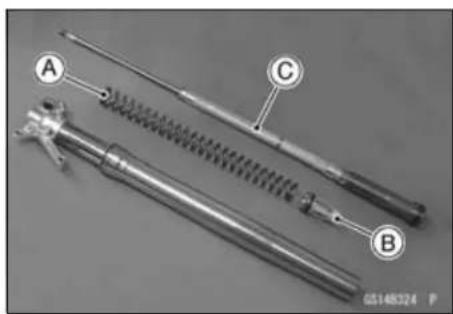
- Temporarily tighten the fork top plug [A] (subtank) using the top plug wrench.
Special Tool - Top Plug Wrench, 49 mm [B]: 57001-1653
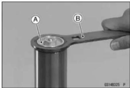
- Clamp the axle holder with a vise.
○Protect the axle holder with a rag when using a vise.
WARNING
Clamping the axle holder part too tight can damage it which will affect riding stability. Do not clamp the axle holder part too tight.
- Compress the outer tube by hands and install the top plug wrench [A] between the axle holder bottom and locknut.
Special Tool - Top Plug Wrench, 49 mm: 57001-1653
WARNING
The fork spring applies pressure to the adjuster assembly and can eject the special tool with substantial force if the tool is not properly and securely placed. Be sure the tool is fully in place as shown in the photo, and keep fingers away to avoid getting them pinched between the tool, adjuster assembly and axle holder.
- Insert the push rod [A] into the piston rod.
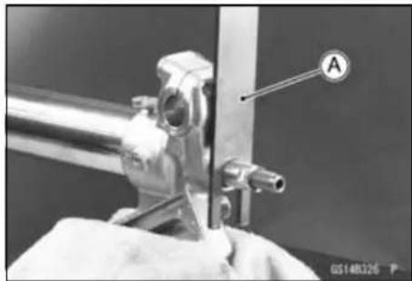
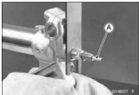
Periodic Maintenance Procedures
- Replace the O-ring and gasket on the adjuster assembly with new ones and apply specified fork oil to the O-ring.
- Turn the locknut [A] counterclockwise until it contacts with the adjuster assembly [B].
- With the locknut held immovable using a wrench, tighten the adjuster assembly to the specified torque.
Torque - Locknut/Adjuster Assembly: 29N·m (3.0 kgf·m, 22 ft·lb)
- With the outer tube compressed by hands, remove the top plug wrench.
- Apply a non-permanent locking agent to the threads of a adjuster assembly.
- Tighten the adjuster assembly [A]. Torque - Adjuster Assembly: 55 N·m (5.6 kgf·m, 41 ft·lb)
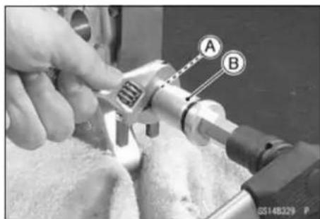
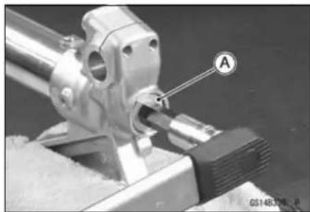
- Loosen and remove the fork top plug (subtank) form the outer tube and slowly slide down the outer tube.
Special Tool - Top Plug Wrench, 49 mm: 57001-1653
- Pour [A] the specified amount of fork oil into the outer tube.
Recommended Oil: KHL15-10 (KAYABA01) or equivalent
Recommended Quantity: 335 mL (11.3 US oz.)
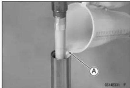
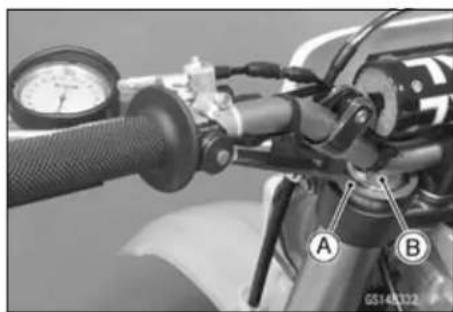
- Raise the outer tube and temporarily tighten the fork top plug (subtank).
Special Tool - Top Plug Wrench, 49 mm [A]: 57001-1653
- After installing the front fork, torque the top plug [B].
Special Tool - Top Plug Wrench, 49 mm: 57001-1653
The torque of fork top plug is specified to 30 N·m (3.1 kgf·m, 22 ft·lb) however, when you use the top plug wrench (special tool) [A], reduce the torque to 90% of the specified value [27 N·m (2.8 kgf·m, 20 ft·lb)] due to the distance [B] between the center of the square hole, where the torque wrench is fitted, and that of the octagonal hole of the wrench.
This torque value [27 N·m (2.8 kgf·m, 20 ft·lb)] is applicable when you use a torque wrench whose length gives leverage of approximately 310 mm between the grip point to the center of the coupling square.
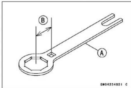
2-54 PERIODIC MAINTENANCE
Periodic Maintenance Procedures
Rear Shock Absorber Inspection
- Bounce [A] the rear of the motorcycle up and down and check for smooth suspension stroke.
- Remove the rear frame (see Rear Frame Removal in the Frame chapter).
- Check for a broken or collapsed spring.
- Check the shock for a bent shaft or oil leaks.
★If the shock does not smoothly or damaged, replace or repair defective parts.
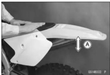
Rear Shock Absorber Oil Change
The oil should be changed in the rear shock absorber at least once per racing season. The frequency for best performance must be based upon riding conditions and rider ability.
- Remove the rear shock absorber from the frame (see Rear Shock Absorber Removal in the Suspension chapter).
- Remove the shock absorber spring (see Spring Replacement in the Suspension chapter).
- Point the valve [A] away from you. slowly release nitrogen gas pressure by pushing down the valve core with a screw driver.
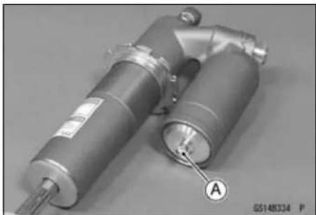
WARNING
The shock contains high-pressure nitrogen gas that when suddenly released can eject oil and internal shock parts at high velocity, causing serious injury. To avoid injury, do not point the reservoir valve toward your face or body when releasing nitrogen gas pressure since an oil mist is often released with the nitrogen. Always release nitrogen gas pressure before disassembling the rear shock absorber to prevent explosive separation of parts.
- Adjust the gas reservoir damping adjusters [A] to the softest position.
- Remove the air bleed bolt [B] and pump the rear shock to drain the oil out the rear shock body.
• Install the air bleed bolt.
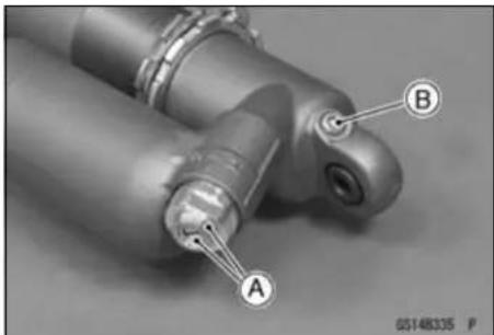
Periodic Maintenance Procedures
- Using the suitable tool [A] and press, push the reservoir cap [B] in 10 mm (0.39 in.).
- Remove the circlip [C] from the gas reservoir.
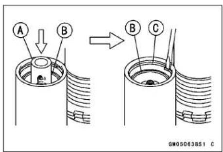
- Pull the gas reservoir cap [B] out of the gas reservoir using the pliers [A].
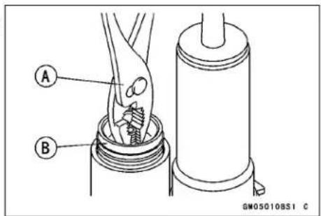
- Pry or tap [A] at the gaps [B] in the stop [C] with suitable tools to free the stop from the rear shock body [D].

- Slide the stop up the top of the piston rod then lightly tap around the seal with a suitable rod and mallet, and push the seal assembly 10 mm (0.39 in.) down.
- Remove the circlip [A].
- Lightly move the piston rod back and forth, and pull out the piston rod assembly.
- Pour the oil out of the rear shock body.
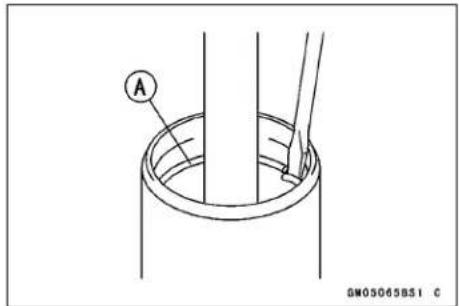
- Visually inspect the piston [A], O-ring [B], and oil seal assy [C].
- If the piston, O-ring and oil seal assy are badly scored, rusty or damaged, replace them.
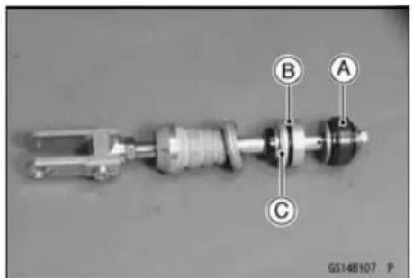
2-56 PERIODIC MAINTENANCE
Periodic Maintenance Procedures
- Using the grinder, shave off the stopper portion [A] of the rod.
- Remove:
Nut [B]
Washer [C]
Piston [D]
• Install the new piston and tighten the locknut.
○Discard a washer or two.
- Pour KYB K2-C (SAE 5W or Bel-Ray SE2 #40) oil into the gas reservoir to 60 \~ 70 mm (2.63 \~ 2.76 in.) [A] from the gas reservoir upper end.
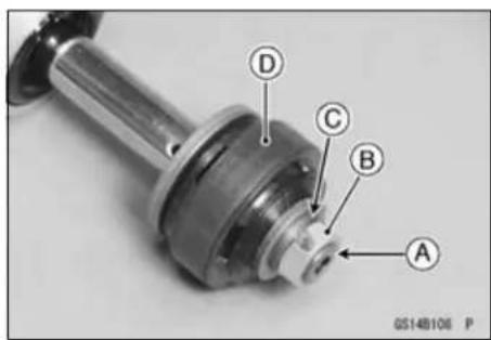
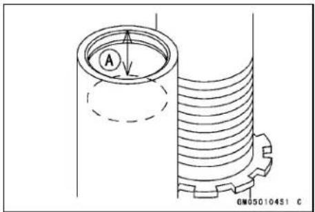
- Check that the bladder [A] on the gas reservoir cap is not partially collapsed.
★If it is, push down the valve core with a screwdriver. - Check the bladder for sign of damage or crack.
★If necessary, replace it with a new one.
NOTICE
Do not use a damaged or partly ally collapsed bladder, because it may burst, gently reducing rear shock performance.
- Apply grease to the lip [B] of the bladder and install the reservoir cap [C].
- Push the bladder into the gas reservoir slowly until it just clears the circlip groove. Wipe out any spilled oil.
NOTICE
Ensure that no air remains in the system.
- Check the circlip for weakening, deformity and flaws.
★If necessary, replace it with a new one.
NOTICE
If weakened, deformed or flawed circlip is used, the gas reservoir cap may not hold when injecting the nitrogen gas. This would allow oil and internal parts to explode out of the reservoir.
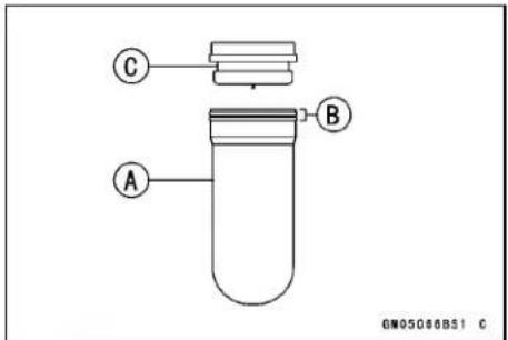
Periodic Maintenance Procedures
- Mount the circlip [A] in the groove in the gas reservoir.
- Pull up the gas reservoir cap [A] against the circlip. The end of the gas reservoir cap must align [B] with the end of the gas reservoir [C].
WARNING
Pressurized nitrogen gas can explode out of the shock reservoir cap if the circlip is not properly installed, allowing oil and internal parts to burst out of the reservoir with great force and cause serious injury. To avoid injury, be sure to install a new circlip in the proper position. If the end of the gas reservoir cap and the end of the gas reservoir are not aligned, the circlip is not correctly fitted in the groove in the gas reservoir or the circlip is deformed and should be replaced with a new one.
- Pour KYB K2-C (SAE 5W or Bel-Ray SE2 #40) oil into the rear shock body to 55 mm (1.77 in.) [A] from the lower end of the rear shock body [B].
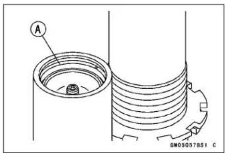
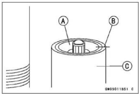
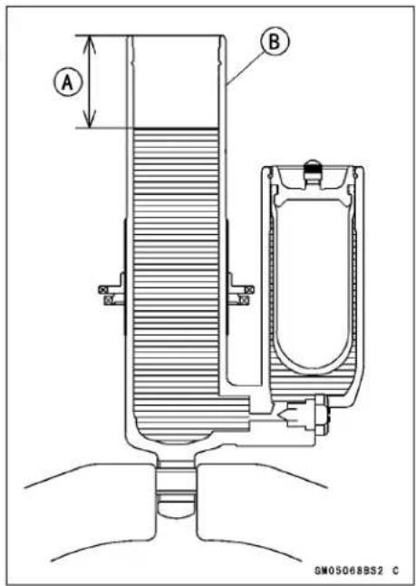
2-58 PERIODIC MAINTENANCE
Periodic Maintenance Procedures
- Insert the piston end [A] of the piston rod assembly into the rear shock body [C] slowly. Do not insert the seal assembly [B] yet. Pump the piston rod until all the air is forced out of the rear shock body.
- Push the seal assembly into the rear shock body until it just clears the circlip groove.
- Check the circlip.
★If it is deformed or damaged, replace it with a new one. - Fit the circlip [A] into the groove in the rear shock body [B].
NOTICE
If the circlip is not a certain fit in the groove in the rear shock body, the piston rod assembly may come out of the shock absorber when injecting the nitrogen gas or riding the motorcycle.
- Pull up the piston rod assembly [C] against the circlip.
- Force the stop [D] into the rear shock body by lightly tapping around the edge of the stop with a mallet.
- Fully extend the piston rod assembly.
- Install the suitable oil cup [A] to the air bleed bolt hole, and fill the specified oil into the cup.
- Purge the air from between the gas reservoir [B] and rear shock body [C] by slowly pumping the piston rod [D] in and out.
- Install the air bleed bolt securely. Torque - Air Bleed Bolt: 6.5 N·m (0.66 kgf·m, 58 in·lb)
- Fully extend the push rod assembly.
- Inject nitrogen gas to a pressure of 50 kPa (0.5 kgf/cm², 7 psi) through the valve on the gas reservoir.
- Check the rear shock body and gas reservoir for oil and gas leaks.
★If there are no leaks, inject the nitrogen gas up to the 980 kPa (10 kgf/cm², 142 psi) pressure.
WARNING
High pressure gas is dangerous and can explode, causing serious injury. To avoid injury, have a qualified mechanic pressurize the shock reservoir with nitrogen gas only. Do not use air or other gases, since they may cause premature wear, rust, fire hazard or substandard performance.
- Install the spring and spring guide.
- Adjust spring preload. Reinstall the rear shock absorber.
- Install the parts removed.
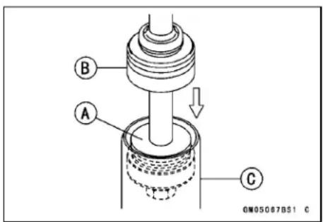
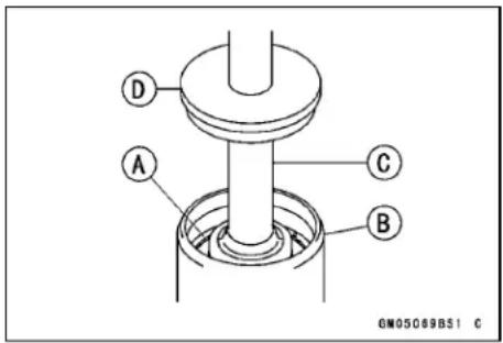
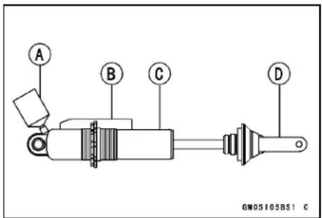
Periodic Maintenance Procedures
Swingarm and Uni-Trak Linkage Inspection
- Check the uni-trak component parts for wear periodically, or whenever excessive play is suspected.
- Using the jack under the frame, raise the rear wheel off the ground.
Special Tool - Jack: 57001-1238
- Push and pull on the swingarm [A], up and down, to check for wear.
★A small amount of play on the swingarm is normal and no corrective action is needed. However, if excessive play is felt, remove the uni-trak parts from the frame and check for wear.
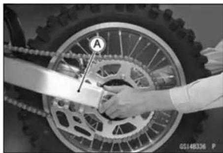
Swingarm and Uni-Track Linkage Pivot Lubricate
- Refer to the Swingarm Bearing Installation and Rocker Arm Bearing Installation in Suspension chapter.
Steering
Steering Inspection
- Using the jack, raise the front wheel off the ground.
Special Tool - Jack: 57001-1238
- With the front wheel pointing straight ahead, alternately nudge each end of the handlebar. The front wheel should swing fully left and right from the force of gravity until the fork hits the stop.
★If the steering binds or catches before the stop, check the routing of the cables, hoses, and harnesses.
★If the steering feels tight, adjust or lubricate the steering.
- Feel for steering looseness by pushing and pulling the forks.
★If you feel looseness, adjust the steering.
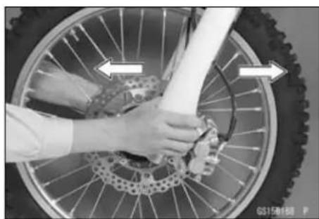
Steering Adjustment
- Using the jack, raise the front wheel off the ground. Special Tool - Jack: 57001-1238
2-60 PERIODIC MAINTENANCE
Periodic Maintenance Procedures
- Remove: Handlebar Pad [A] Headlight [B] (see Headlight Removal/Installation in the Electrical System chapter)
- Remove: Handlebar Clamp Bolts [A] Handlebar Clamps [B] Handlebar [C] (from holder)
- Loosen the front fork upper clamp bolts [A], and remove the steering stem head nut [B] and steering stem head [C].
- Turn the steering stem nut [A] with the steering stem nut wrench [B] to obtain the proper adjustment. ★If the steering is too tight, loosen the stem nut a fraction of a turn; if the steering is too loose, tighten the nut a fraction of a turn.
Special Tool - Steering Stem Nut Wrench: 57001-1100
NOTE
○ Turn the stem nut 1/8 turn at a time maximum.
- Install the steering stem head. - Tighten the following: Torque - Steering Stem Head Nut: 98 N·m (10 kgf·m, 72 ft·lb) Upper Front Fork Clamp Bolts: 23 N·m (2.3 kgf·m, 17 ft·lb)
NOTE
○ Tighten the two clamp bolts alternately two times to ensure even tightening torque.
- Check the steering again. ★If the steering is too tight or too loose, repeat the adjustment as mentioned above.
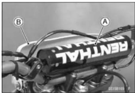
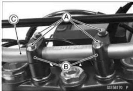
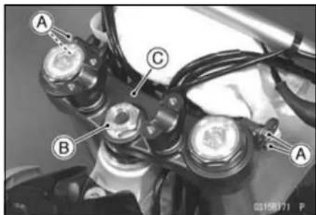
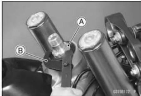
Periodic Maintenance Procedures
- Install the handlebar [B] on the handlebar holder so that the protruded scales of the both side adjust to the same width [A].
- Route the hose according to Cable, Wire, and Hose Routing section in the Appendix chapter.
- Apply 2-stroke oil to the threads of the handlebar clamp bolts.
- Install the handlebar clamp so that center [D] of the handlebar clamps [C] and handlebar bridge [E] align.
Torque - Handlebar Clamp Bolts: 25 N·m (2.5 kgf·m, 18 ft·lb)
Front [F]
- After tighten, make sure space [A] [B] of the ahead and back are same width.
- Install the handlebar pad and number plate.
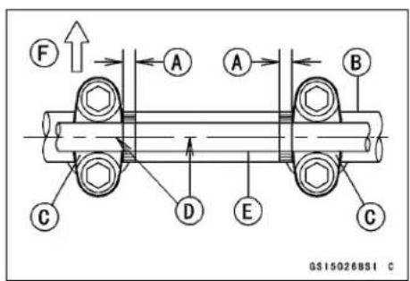
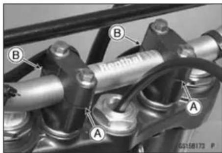
Stem Bearing Lubrication
- Remove the steering stem (see Steering Stem, Stem Bearing Removal in the Steering chapter).
- Using a high-flash point solvent, wash the upper and lower tapered rollers in the cages, and wipe the upper and lower outer races, which are press-fitted into the frame head pipe, clean off grease and dirt.
- Visually check the outer races and the rollers.
★Replace the bearing assemblies if they show wear or damage. - Pack the upper and lower tapered roller bearings [A] in the cages with grease, and apply a light coat of grease to the upper and lower outer races.
• Install the steering stem, and adjust the steering (see Steering Adjustment).
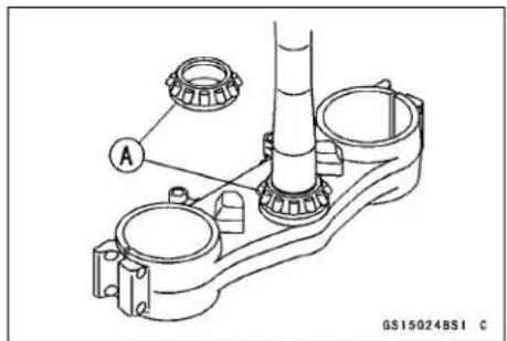
Frame
Frame Inspection
- Clean the frame with steam cleaner.
- Visually inspect the frame and rear frame for cracks, dents, bending, or warp.
★If there is any damage to the frame, replace it.
WARNING
A repaired frame may fail in use, possibly causing an accident resulting in injury or death. If the frame is bent, dented, cracked, or warped, replace it.
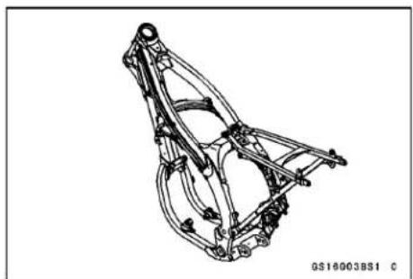
2-62 PERIODIC MAINTENANCE
Periodic Maintenance Procedures
Electrical System
Spark Plug Cleaning and Inspection
- Remove:
Seat (see Seat Removal in the Frame chapter)
Fuel Tank (see Fuel Tank Removal in the Fuel System chapter)
Spark Plug Cap
- Clean the plug hole [A], using the compressed air [B].
- Remove the spark plug [A], using the spark plug wrench [B].
Special Tool - Spark Plug Wrench: 57001-1262
Owner's Tool - Spark Plug Wrench, 16 mm: 92110-0005
- Clean the spark plug, preferably in a sandblasting device, and then clean off any abrasive particles. The plug may also be cleaned using a high-flash point solvent and a wire brush or other suitable tool.
★If the spark plug electrodes are corroded or damaged, or if the insulator is cracked, replace the plug. Use the standard spark plug.
- Measure the gap [A] with a wire-type thickness gauge.
★If the gap is incorrect, carefully bend the side electrode [B] with a suitable tool to obtain the correct gap.
Spark Plug Gap
Standard: 0.8 \~ 0.9 mm (0.03 \~ 0.04 in.)
• Install the spark plug.
Torque - Spark Plug: 13 N·m (1.3 kgf·m, 115 in·lb)
- Fit the plug cap securely.
○Pull the spark plug cap [A] to make sure the installation of the spark plug cap.
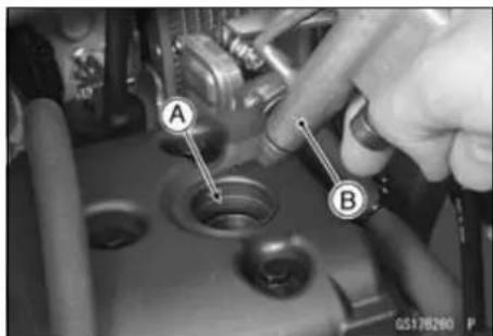
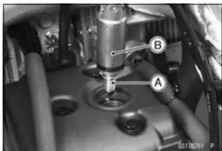
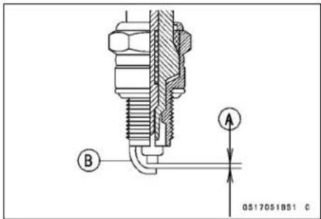

Cable Inspection
Lubrication
- Before lubricating each part, clean off any rusty spots with rust remover and wipe off any grease, oil, dirt, or grime.
- Lubricate the points listed below with indicated lubricant.
NOTE
○ Whenever the vehicle has been operated under wet or rainy conditions, or especially after using a high-pressure water spray, perform the general lubrication.
Periodic Maintenance Procedures
Points: Lubricate with Grease.
Clutch Inner Cable Upper and Lower Ends [A] Hot Start Inner Cable Upper End Throttle Inner Cable Upper End
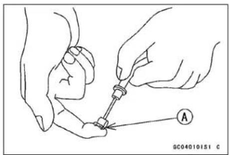
Cables: Lubricate with Rust Inhibitor.
Throttle Cables Clutch Cable Hot Starter Cable
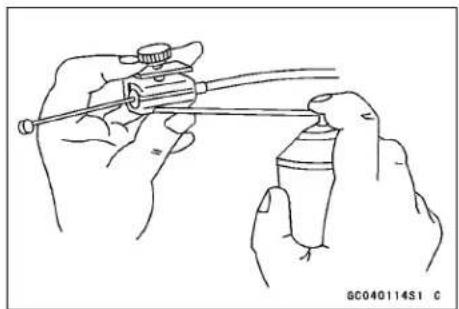
- With the cable disconnected at the both ends, the cable should move freely [A] within the cable housing.
★If cable movement is not free after lubricating, if the cable is frayed [B], or if the cable housing is kinked [C], replace the cable.
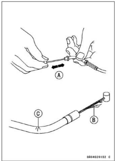
Nut, Bolt, and Fastener Tightness Inspection Tightness Inspection
- Check the tightness of the bolts and nuts listed here in accordance with the Periodic Maintenance Chart. Also, check to see that each cotter pin is in place and in good condition.
NOTE
○ For the engine fasteners, check the tightness of them when the engine is cold (at room temperature).
2-64 PERIODIC MAINTENANCE
Periodic Maintenance Procedures
★If there are loose fasteners, retorque them to the specified torque following the specified tightening sequence. Refer to the Torque and Locking Agent section of the General Information chapter for torque specifications. For each fastener, first loosen it by 1/2 turn, then tighten it.
★If cotter pins are damaged, replace them with new ones.
Nut, Bolt and Fastener to be checked
Wheels:
Spoke Nipples
Front Axle Nut
Front Axle Clamp Bolt
Rear Axle Nut Cotter Pin
Rear Axle Nut
Final Drive:
Chain Adjuster Locknut
Rear Sprocket Nuts
Brakes:
Front Master Cylinder Clamp Bolts
Brake Lever Pivot Nut
Front Caliper Mounting Bolts
Brake Pedal Bolt
Rear Brake Joint Cotter Pin
Rear Master Cylinder Mounting Bolts
Rear Caliper Mounting Bolts
Suspension:
Front Fork Clamp Bolts
Front Fender Bolts
Rear Shock Absorber Mounting Bolts, Nuts
Swingarm Pivot Nut
Steering:
Steering Stem Head Nut
Handlebar Clamp Bolts
Engine:
Throttle Cable Adjuster Locknuts
Engine Mounting Bolts, Nuts
Shift Pedal Bolt
Muffler Mounting Bolts
Exhaust Pipe Holder Nuts
Clutch Cable Adjuster Locknut
Clutch Lever Pivot Nut
Others:
Footpeg Cotter Pins
Rear Frame Bolts
Fuel System
Table of Contents
Exploded View 3-2
Specifications 3-6
Special Tool 3-7
Throttle Grip and Cable 3-8
Free Play Inspection 3-8
Free Play Adjustment.... 3-8
Throttle Cable Replacement 3-8
Throttle Cable Lubrication 3-9
Throttle Cable Inspection 3-9
Hot Starter Cable Removal 3-10
Hot Starter Cable Installation 3-10
Hot Starter Lever Free Play Inspection.... 3-10
Hot Starter Lever Free Play Adjustment 3-11
Hot Starter Cable Lubrication.... 3-11
Hot Starter Cable Inspection.... 3-11
Carburetor 3-12
Idle Speed Inspection 3-12
Idle Speed Adjustment.... 3-12
Service Fuel Level Inspection 3-12
Service Fuel Level Adjustment 3-13
Carburetor Removal.... 3-14
Carburetor Installation.... 3-16
Fuel Inspection 3-17
Carburetor Disassembly 3-17
Carburetor Cleaning 3-20
Carburetor Inspection 3-21
Carburetor Assembly 3-22
Air Cleaner.... 3-28
Air Cleaner Housing Removal 3-28
Air Cleaner Housing Installation.... 3-28
Element Removal.... 3-28
Element Installation.... 3-29
Element Cleaning and Inspection 3-29
Fuel Tank 3-30
Fuel Tank Removal 3-30
Fuel Tank Installation 3-30
Fuel Filter Removal 3-30
Fuel Filter Installation 3-30
Fuel Tank, Filter and Tap Cleaning 3-31
Fuel Tap and Filter Inspection.... 3-31
3-2 FUEL SYSTEM
Exploded View
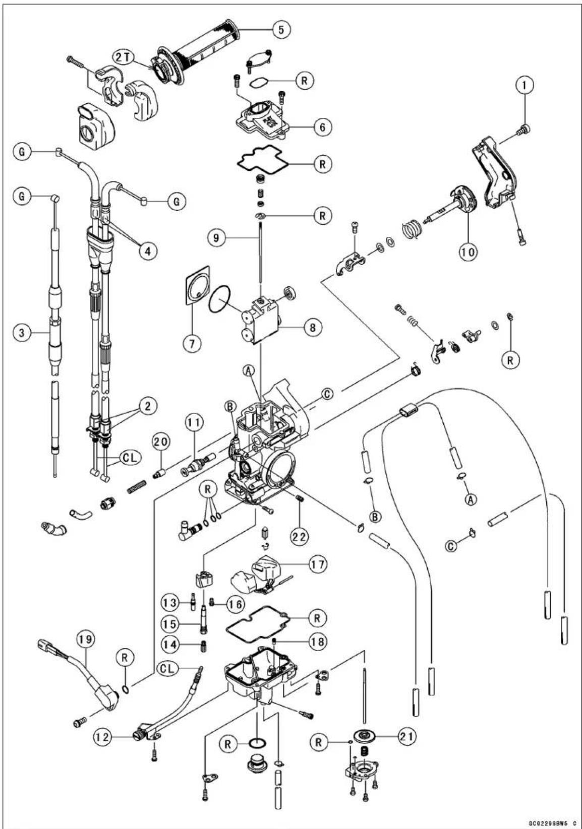
Exploded View
| No. | Fastener | Torque | Remarks | ||
| N·m kgf | m ft·lb | ||||
| 1 | Throttle Pulley Cover Bolt | 3.4 | 0.35 | 30 in·lb | |
| 2 | Throttle Cable Mounting Bolts | 6.9 | 0.70 | 61 in·lb | |
- Hot Starter Cable
- Throttle Cables
- Throttle Grip
- Carburetor Cap
- Throttle Valve Plate
- Throttle Valve
- Jet Needle
- Throttle Pulley Shaft
- Choke Knob
- Idle Adjusting Screw
- Pilot Jet
- Main Jet
- Needle Jet
- Starter Jet
- Float
- Leak Jet
- Throttle Sensor
- Hot Start Plunger
-
Slow Air Jet
CL: Apply cable lubricant.
G: Apply grease.
2T: Apply 2-stroke oil.
R: Replacement Parts -
Acceleration Pump Diaphragm
3-4 FUEL SYSTEM
Exploded View
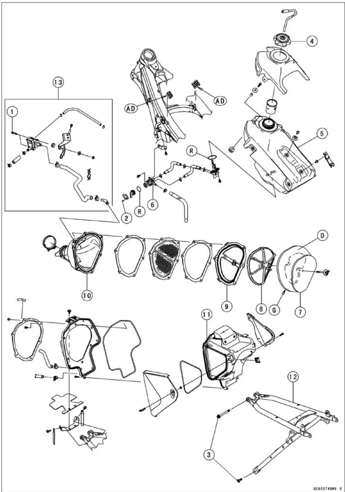
Exploded View
| No. | Fastener | Torque | Remarks | ||
| N·m kgf | m ft·lb | ||||
| 1 | Vacuum Switch Valve Bracket Bolts | 9.8 | 1.0 | 87 in·lb | |
| 2 | Fuel Tap Knob Screws | 0.80 | 0.080 | 7.0 in·lb | |
| 3 | Rear Frame Mounting Bolts | 34 | 3.5 | 25 | |
- Fuel Tank Cap
- Fuel Tank
- Fuel Tap
- Element
- Frame
- Holder
- Air Cleaner Duct
- Air Cleaner Housing
- Rear Frame
- U.S.A., California, and Canada Models
AD: Apply adhesive cement.
G: Apply grease.
O: High-quality foam air filter oil.
R: Replacement Parts
3-6 FUEL SYSTEM
Specifications
| Item Standard | |
| Throttle Grip and Cable | |
| Throttle Grip Free Play | 2 ~ 3 mm (0.08 ~ 0.12 in.) |
| Hot Starter Lever Free Play | 0.5 ~ 1.0 mm (0.02 ~ 0.04 in.) |
| Carburetor | |
| Make/Type KEIHIN FCR-MX40 | |
| Starter Jet #55 | |
| Leak Jet #50 | |
| Main Jet #145 | |
| Throttle Valve Cutaway 1.5 | |
| Jet Needle NLZU, (EUR) (AU) NCVU | |
| Jet Needle Clip Position | (EUR) (AU) 2th groove from the top |
| Slow Jet #45 | |
| Slow Air Jet | #100 |
| Pilot Air Screw (turns out) | 2 1/2, (EUR)(AU) 2 (reference) |
| Service Fuel Level(below the bottom edge of the carb. body) | 6.5 ±1 mm (0.26 ±0.04 in.) |
| Float Height | 8 ±1 mm (0.3 ±0.04 in.) |
| Air Cleaner | |
| Air Cleaner Element Oil | High quality form air filter oil |
Special Tool
Fuel Level Gauge, M18 × 1.0: 57001-122
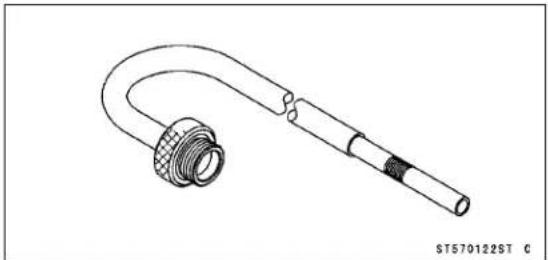
3-8 FUEL SYSTEM
Throttle Grip and Cable
If the throttle grip has excessive free play due to cable stretch or misadjustment, there will be a delay in throttle response. Also, the throttle valve may not open fully at full throttle. On the other hand, if the throttle grip has no play, the throttle will be hard to control, and the idle speed will be erratic. Check the throttle grip play periodically in accordance with the Periodic Maintenance Chart, and adjust the play if necessary.
The throttle cable routing is shown in Cable, Wire, and Hose Routing Section in the Appendix chapter.
Free Play Inspection
- Refer to the Throttle Grip Free Play Inspection in the Periodic Maintenance chapter.
Free Play Adjustment
- Refer to the Throttle Grip Free Play Adjustment in the Periodic Maintenance chapter.
Throttle Cable Replacement
- Slide out the dust cover [A] and cable housing dust cover [B].
- Unscrew the screws [A]. - Separate the throttle cable housing [B].
- Free the tips [A] from the grip [B].


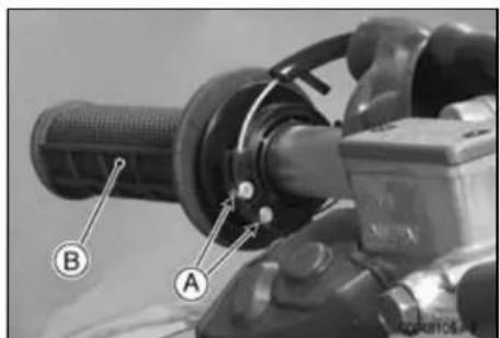
Throttle Grip and Cable
- Remove the exhaust pipe (see Muffler Removal in the Engine Top End chapter).
- Unscrew the bolt [A].
- Remove the throttle pulley cover [B].
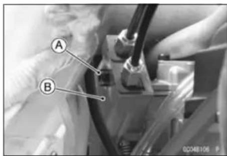
- Loosen the mounting bolts [A].
- Remove the cables [B] from the carburetor.
- Free the tips [C] from the pulley.
- Pull out the cables from the frame.
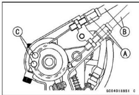
- Lubricate the cable.
- Apply grease to the tips of the cables.
- Install the throttle cable lower ends [A].
• Install the mounting bolts [B] to the holder as shown.
• Install the throttle pulley cover.
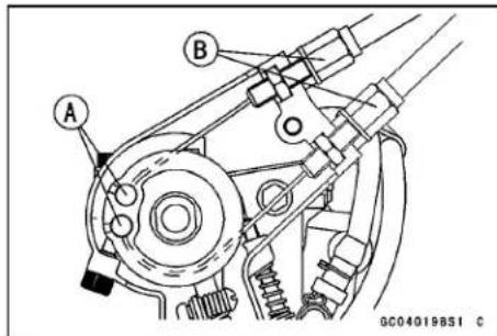
Torque - Throttle Cable Mounting Bolts: 6.9 N·m (0.70 kgf·m, 61 in·lb)
Throttle Pulley Cover Bolt: 3.4 N·m (0.35 kgf·m, 30 in·lb)
- Install the throttle cable in accordance with the Cable, Wire, and Hose Routing section in the Appendix chapter.
● After the installation, adjust each cable properly.
WARNING
Operation with incorrectly routed or improperly adjusted cables could result in an unsafe riding condition. Be sure the cables are routed correctly and properly adjusted.
Throttle Cable Lubrication
- Whenever the throttle cable is removed or in accordance with the Periodic Maintenance Chart, lubricate the these cables (see Lubrication in the Periodic Maintenance chapter).
○Apply a thin coating of grease to the cable upper or lower ends.
○Use a commercially available pressure cable lubricator to lubricate these cables.
Throttle Cable Inspection
- Refer to the Cable Inspection in the Periodic Maintenance chapter.
3-10 FUEL SYSTEM
Throttle Grip and Cable
Hot Starter Cable Removal
- Slide the clutch lever dust cover [A] back.
- Loosen the locknut [B].
- Turn in the adjuster [C] fully.
-
Remove the cable end [D] from the hot starter lever [E].
-
Remove: Fuel Tank (see Fuel Tank Removal)
-
Unscrew the plunger cap bolt [A] and remove the cable end.
-
Disassemble the cable end from the plunger [A]. Spring [B] Plunger Cap Assy [C]
- Remove: Clamps [A] (Open) Hot Starter Cable [B]
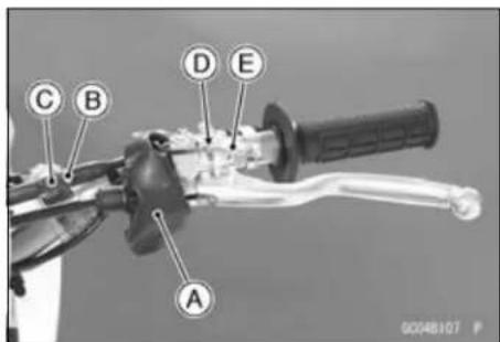
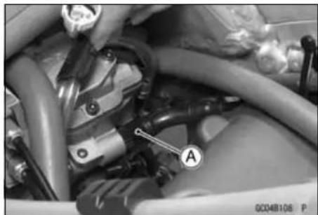

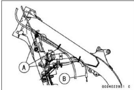
Hot Starter Cable Installation
- Install the hot starter cable in accordance with the Cable, Wire and Hose Routing section in the appendix chapter.
- After the installation, adjust the cable properly.
WARNING
Operation with incorrectly routed or improperly adjusted cables could result in an unsafe riding condition. Be sure the cables are routed correctly and properly adjusted.
Hot Starter Lever Free Play Inspection
- Refer to the Hot Starter Lever Free Play Inspection in the Periodic Maintenance chapter.
Throttle Grip and Cable
Hot Starter Lever Free Play Adjustment
- Refer to the Hot Starter Lever Free Play Inspection in the Periodic Maintenance chapter.
Hot Starter Cable Lubrication
- Whenever the hot starter cable is removed or in accordance with the Periodic Maintenance Chart, lubricate the these cable (see Lubrication in the Periodic Maintenance chapter).
Hot Starter Cable Inspection
- Refer to the Cable Inspection in the Periodic Maintenance chapter.
Carburetor
Since the carburetor regulates and mixes the fuel and air going to the engine, there are two general types of carburetor trouble: too rich a mixture (too much fuel), and too lean a mixture (too little fuel). Such trouble can be caused by dirt, wear, maladjustment, or improper fuel level in the float chamber. A dirty or damaged air cleaner can also alter the fuel to air ratio.
Idle Speed Inspection
- Refer to the Idle Speed Inspection in the Periodic Maintenance chapter.
Idle Speed Adjustment
- Refer to the Idle Speed Adjustment in the Periodic Maintenance chapter.
Service Fuel Level Inspection
WARNING
Gasoline is extremely flammable and can be explosive under certain conditions. Always stop the engine and do not smoke. Make sure the area is well-ventilated and free from any source of flame or sparks; this includes any appliance with a pilot light.
- Turn the fuel tap to the OFF position.
- Remove the fuel tank (see Fuel Tank Removal).
- Remove the carburetor, and hold it in true vertical position on a stand. The fuel hose and carburetor cable do not have to be removed to inspect the fuel level [A].
- Put the fuel tank on a bench, and connect the fuel tap to the carburetor using a suitable hose.
- Remove the drain plug from the bottom of the float bowl, and screw a fuel level gauge [B] into the plug hole.
Special Tools - Fuel Level Gauge, M18 × 1.0: 57001-122
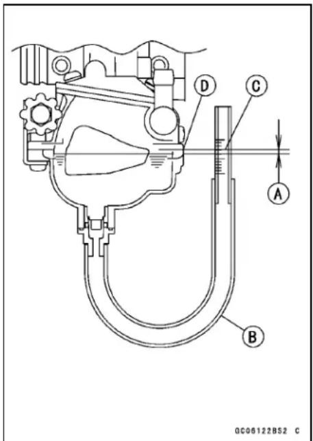
- Hold the gauge vertically against the side of the carburetor body so that the "zero" line [C] is several millimeters higher than the bottom edge [D] of the carburetor body.
- Turn the fuel tap to the ON position to feed fuel to the carburetor.
- Wait until the fuel level in the gauge settles.
- Keeping the gauge vertical, slowly lower the gauge until the "zero" line is even with the bottom edge of the carburetor body.
NOTE
☐ Do not lower the "zero" line below the bottom edge of the carburetor body. If the gauge is lowered and then raised again, the fuel level measure shows somewhat higher than the actual fuel level. If the gauge is lowered too far, dump the fuel out of it into a suitable container and start the procedure over again.
Carburetor
- Read the fuel level in the gauge and compare it to the specification.
Service Fuel Level (below the bottom edge of the carb. body)
Standard: -6.5 ±1 mm (-0.26 ±0.04 in.)
★If the fuel level is incorrect, adjust it.
- Turn the fuel tap to the OFF position and remove the fuel level gauge.
• Install the drain plug on the bottom of the float bowl.
Service Fuel Level Adjustment
WARNING
Gasoline is extremely flammable and can be explosive under certain conditions. Always stop the engine and do not smoke. Make sure the area is well-ventilated and free from any source of flame or sparks; this includes any appliance with a pilot light.
- Remove the carburetor, and drain the fuel into a suitable container.
- Remove the float bowl (see Carburetor Disassembly).
- Drive out the pivot pin [A] and remove the float [B] with valve needle [C].
- Bend the tang [A] on the float arm very slightly to change the float height. Increasing the float height lowers the fuel level and decreasing the float height raises the fuel level.
Float Height
Standard: 8 ±1 mm (0.3 ±0.04 in.)
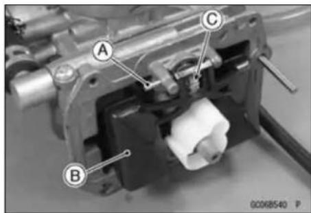
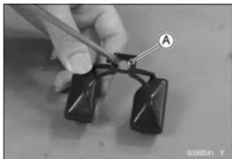
Carburetor
NOTE
○Float height [A] is the distance from the float bowl mating surface [B] of the carburetor body (with the gasket removed) to the top of the float [C]. Measure the height with the carburetor upside down.
○Do not push the needle rod [D] in during the float height measurement.
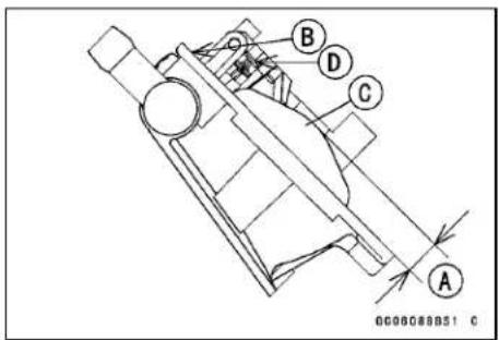
- Assemble the carburetor, and recheck the fuel level.
★If the fuel level cannot be adjusted by this method, the float or the float valve is damaged.
Carburetor Removal
WARNING
Gasoline is extremely flammable and can be explosive under certain conditions. Always stop the engine and do not smoke. Make sure the area is well-ventilated and free from any source of flame or sparks; this includes any appliance with a pilot light.
-
Turn the fuel tap lever [A] to the OFF position.
○Slide off the clamp [B] and pull the fuel hose [C] off the tap. -
Remove the fuel tank (see Fuel Tank Removal).
- Disconnect the throttle sensor connector [A].
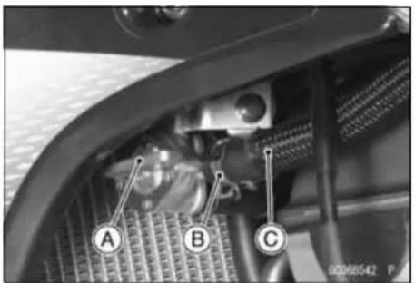
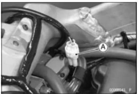
Carburetor
- Loosen the clamp screw [A] fully.
- Remove: Engine Mounting Bracket Bolts [B] Right Engine Mounting Bracket [C]
- Remove:
Seat (see Seat Removal in the Frame chapter) Side Covers (see Side Cover Removal in the Frame chapter)
Muffler (see Muffler Removal in the Engine Top End chapter)
Fuel Tank (see Fuel Tank Removal)
Starter Motor (see Starter Motor Removal in the Electrical System chapter)
Battery (see Battery Removal in the Electrical System chapter)
Igniter (see Igniter Removal in the Electrical System chapter)
Tail Light Connector (see Tail Light Removal in the Electrical System chapter)
Rear Frame Bolts [A]
- Pull out the rear frame [B] with the air cleaner housing from the carburetor.
- Unscrew the hot start plunger cap bolt [A].
- Remove the hot start plunger.
- Unscrew the throttle pulley cover bolt [A].
- Remove the throttle pulley cover [B].
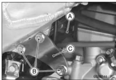
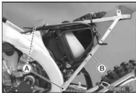
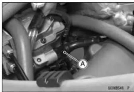
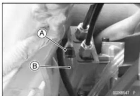
Carburetor
- Loosen the mounting bolts [A].
- Pull out the end of the throttle cables [B].
- Free the tips [C].
- Remove the carburetor to the right side of the frame.
- Drain the fuel from the float bowl by removing the drain plug. After draining, install the drain plug securely.
- After removing the carburetor, push a clean, lint-free towel into the carburetor holder and the air cleaner duct to keep dirt or other foreign material from entering.
WARNING
If dirt or dust is allowed to pass through into the carburetor, the throttle may become stuck, possibly causing accident. Replace the air cleaner element according to the maintenance chart.
NOTICE
If dirt gets through into the engine, excessive engine wear and possibly engine damage will occur.
Carburetor Installation
- Install:
Throttle Cables (see Throttle Cable Replacement) Hot Start Plunger (see Hot Starter Cable Installation)
- Tighten:
Torque - Throttle Pulley Cover Bolt: 3.4 N·m (0.35 kgf·m, 30 in·lb)
Throttle Cable Mounting Bolts: 6.9 N·m (0.70 kgf·m, 61 in·lb)
- When installing the carburetor into the carburetor holder, fit the projection [A] of the carburetor with the groove [B] on the holder.
○Fit the claw [A] of the clamp onto the groove [B] of the intake duct.
- Tighten the clamps securely.
- Route the air vent and overflow hoses properly (see Cable, Wire, and Hose Routing Section in the Appendix chapter).
NOTICE
Always keep the hoses free of obstruction, and make sure they do not get pinched by the chain or shock absorber.
- Connect the throttle sensor connector.
- After installing the carburetor, do the following.
○Turn the fuel tap to the ON position, and check for fuel leakage from the carburetor.
WARNING
Fuel spilled from the carburetor is hazardous.
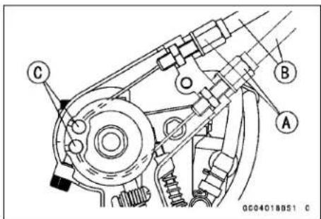
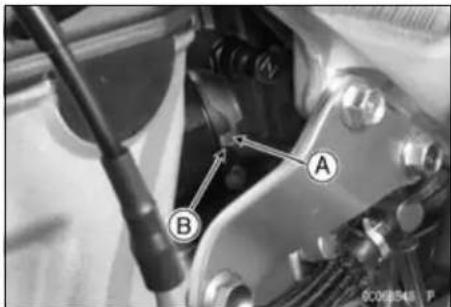
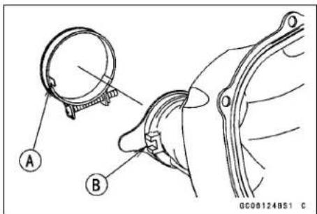
Carburetor
○Adjust the following items if necessary:
Throttle Cable (see Throttle Grip Free Play Adjustment in the Periodic Maintenance chapter)
Idle Speed (see Idle Speed Adjustment in the Periodic Maintenance chapter)
Fuel Inspection
- Refer to the Fuel Inspection in the Periodic Maintenance chapter.
Carburetor Disassembly
- Remove the carburetor, and drain the fuel into a suitable container (see Carburetor Removal).
-
Remove all vent hoses [A] and fuel hose [B].
-
Unscrew the screw [A].
- Pull out the fuel hose fitting [B].
- Unscrew the carburetor cap bolts [A].
- Remove the carburetor cap [B].
- Unscrew the throttle valve link screw [A].
- Pull out the throttle valve assembly [B].
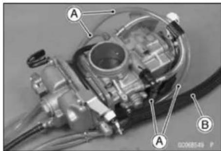
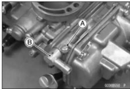
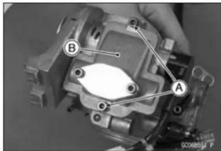
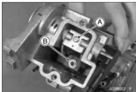
3-18 FUEL SYSTEM
Carburetor
- Disassemble the throttle valve assembly; jet needle holder [A] (unscrew), spring [B], retainer [C], jet needle with circlip [D], O-ring with throttle valve plate [E], and throttle valve [F].
- Remove the choke knob/starter plunger assembly [A] from the carburetor.
- Remove the throttle pulley shaft [A] with the spring [B], steel washer [C], plastic washer [D], and throttle valve link [E].
Turn the throttle pulley shaft [A] clockwise while holding down the acceleration pump lever [B] and clear the idle stop screw [C] to the stopper [D] of the pulley.
- Turn in the pilot air screw [A] fully but not tightly and count the number of turns (Australia and Europe models). ○Record this number as the manufacture-set number of turns out. - Unscrew the pilot air screw (Australia and Europe models).
NOTE
○Do not remove the pilot air screw plug (U.S.A, California, and Canada models).
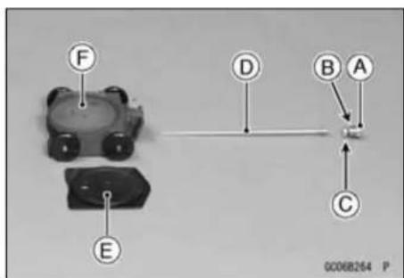
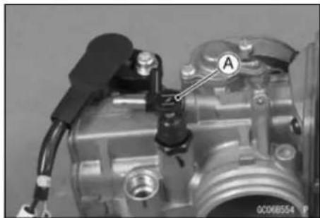
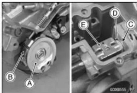
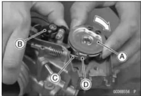
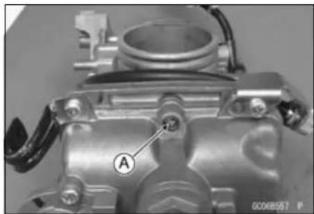
Carburetor
- Unscrew the screws [A].
- Remove the acceleration pump cover [B] from the carburetor.
- Remove the spring [A], diaphragm [B], and the O-rings [C].
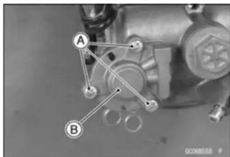
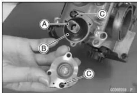
- Remove the following parts from the carburetor body.
[A] Idle Adjusting Screw
[B] Screws
[C] Clamps
[D] Float Bowl
[E] Leak Jet
[F] O-ring
[G] Pin
[H] Float
[I] Main Jet
[J] Needle Jet
[K] Starter Jet
[L] Pilot Jet
[M] Pilot Air Jet
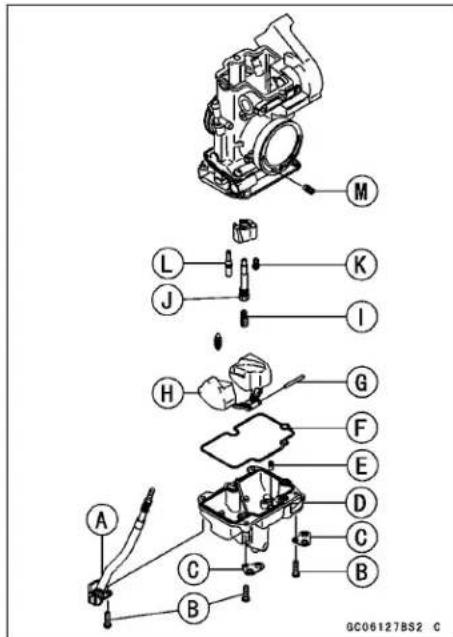
- Pull out the push rod [A] of the acceleration pump.
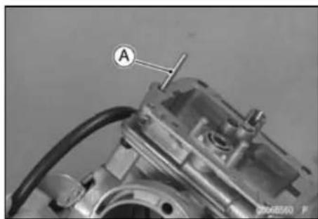
Carburetor
- Remove:
E-clip [A]
Washer [B] - Pull out the acceleration pump lever assembly [C] as a set.
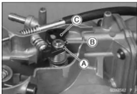
- Remove the throttle sensor mounting bolt [A].
- Before removing the throttle sensor [B], mark [C] the carburetor body and sensor so that it can be installed later in the same position.
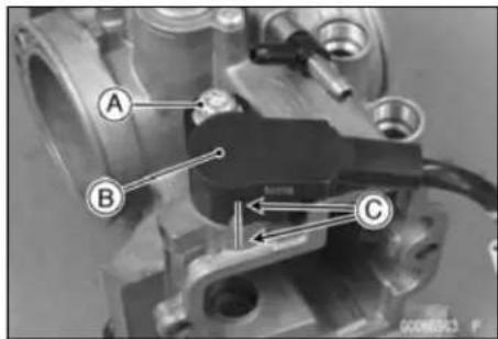
Carburetor Cleaning
WARNING
Gasoline and low-flash point solvents can be flammable and/or explosive and cause severe burns. Clean the carburetor in a well-ventilated area, and take care that there are no sparks or flame anywhere near the working area; this includes any appliance with a pilot light. Do not use gasoline or a low-flash point solvent to clean the carburetor.
- Make sure the fuel tap is in the OFF position.
- Remove the carburetor (see Carburetor Removal).
- Drain the fuel in the carburetor.
- Disassemble the carburetor (see Carburetor Disassembly).
NOTICE
Do not use compressed air on an assembled carburetor, the float may be deformed by the pressure. Remove as many rubber or plastic parts from the carburetor as possible before cleaning the carburetor with a cleaning solution. This will prevent damage or deterioration of the parts. Do not use a strong carburetor cleaning solution which could attack the plastic parts; instead, use a mild high-flash point cleaning solution safe for plastic parts. Do not use wire or any other hard instrument to clean carburetor parts, especially jets, as they may be damaged.
Carburetor
- Immerse all the metal parts in a carburetor cleaning solution.
- Rinse the parts in water.
● After the parts are cleaned, dry them with compressed air. - Blow through the air and fuel passages with compressed air [A].
- Assemble the carburetor, and install it on the motorcycle.
Carburetor Inspection
WARNING
Gasoline is extremely flammable and can be explosive under certain conditions. Always stop the engine and do not smoke. Make sure the area is well-ventilated and free from any source of flame or sparks; this includes any appliance with a pilot light.
- Remove the carburetor (see Carburetor Removal).
- Before disassembling the carburetor, check the fuel level (see Service Fuel Level Inspection).
★If the fuel level is incorrect, inspect the rest of the carburetor before correcting it. - Turn the throttle pulley to check that the throttle valve [A] moves smoothly and returns by spring pressure.
★If the throttle valve does not move smoothly. Replace the throttle valve or pulley spring. - Disassemble the carburetor (see Carburetor Disassembly).
- Clean the carburetor (see Carburetor Cleaning).
- Check the tapered portion [A] of the pilot air screw [B] for wear or damage.
★If the pilot air screw is worn or damaged on the tapered portion, it will prevent the engine from idling smoothly. Replace the carburetor.
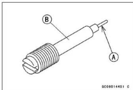
Carburetor
- Remove the float valve needle.
- Check the plastic tip [A] of the float valve needle [B] for wear.
★If the needle is worn as shown right [C], replace the valve needle. - Push the rod [D] in the valve needle, then release it.
★If the rod does not come out fully by spring tension, replace the valve needle.
Push and release [E]
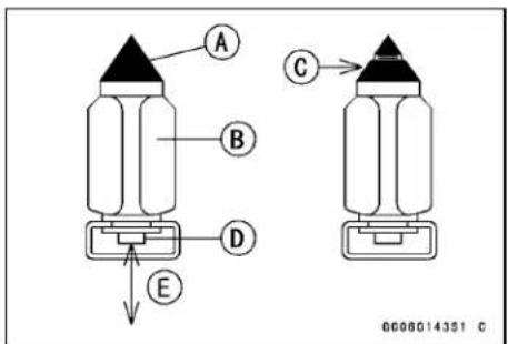
- Remove the starter jet.
- Check the slow jet for any damage.
★If the slow jet is damaged, replace it with a new one. - Remove the throttle valve and jet needle.
- Inspect the outside of the throttle valve and plate for scratches and abnormal wear.
★If it is badly scratched or worn, replace the throttle valve or plate. - Inspect the inside of the carburetor body for these same faults.
★If it is badly scratched or worn, replace the entire carburetor. - Check the jet needle for wear.
- For the throttle sensor inspection, see the Electrical System chapter.
★A worn jet needle should be replaced. - Clean the fuel and air passages with a high-flash point solvent and compressed air.
Carburetor Assembly
- Clean the disassembly parts before assembling.
○Clean the fuel and air passages with a high-flash point solvent and compressed air [A].
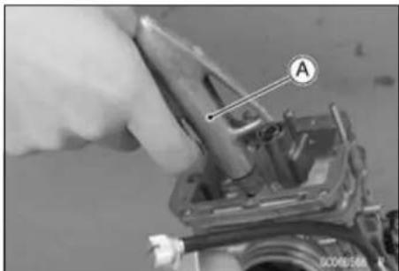
- Set up the acceleration pump lever assembly as shown.
Acceleration pump lever [A]
Spring [B]
Push Rod Holder [C]
Adjusting Screw with Spring [D]
○Fit the spring end on the stopper [E] of the push rod holder.
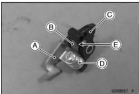
Carburetor
- Install the return spring [A] to the acceleration pump lever [B].
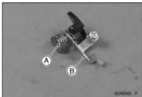
- Install the acceleration pump lever assembly to the carburetor body.
○Fit the end [A] of the return spring into the recess [B] on the carburetor body.
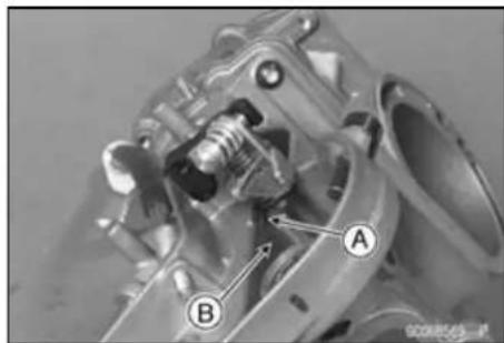
• Install: Washer [A] E-clip [B]
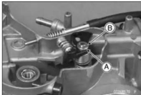
- Apply thin coat silicone grease to the shaft.
- Fit the hook [A] of the return spring onto the stopper [B] of the throttle cable pulley.
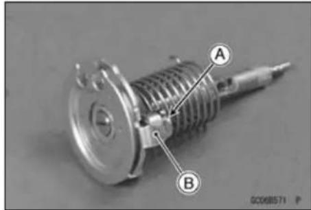
- Insert the throttle cable pulley shaft [A] and install the steel washer [B], nylon washer [C] and valve link [D].
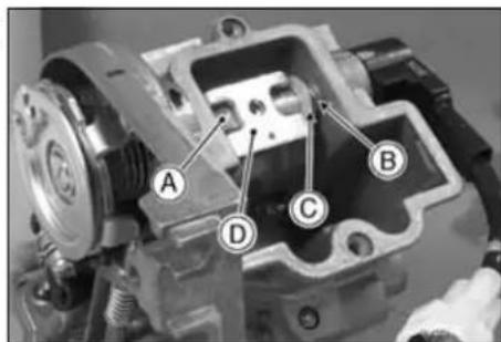
3-24 FUEL SYSTEM
Carburetor
○Fit the end [A] of the return spring into the recess [B] of the carburetor body.
- Turn the pulley counterclockwise [A] while holding down the acceleration pump lever [B] and clear the stopper [C] of the pulley from the throttle stop screw head [D].
- Install the push rod [A] into the push rod holder [B].
● Assembly: Throttle Valve [A] Jet Needle [B] Circlip [C] Retainer [D] Spring [E] Jet Needle Holder [F] O-ring [G] Throttle Valve Plate [H]
○Assemble the valve plate so that the hole side [I] down ward.
- Apply a non-permanent locking agent to the link screw.
- Insert the throttle valve assembly.
○Insert the link rollers [A] on the throttle link into the slits [B] of the throttle valve. - Tighten the screw.
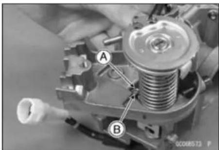
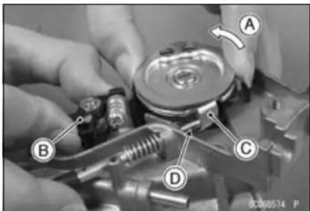
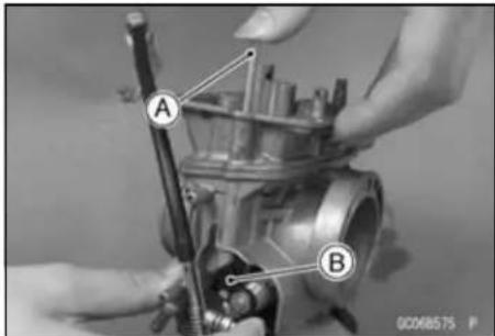
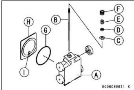
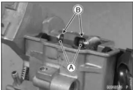
Carburetor
- Apply a grease to the O-ring [A].
- Fit the stopper [B] of the throttle sensor onto the projection [C] on the throttle cable pulley shaft.
○Install the throttle sensor so that the marks aligns and check it position (see Throttle Sensor Inspection in the Electrical System chapter).
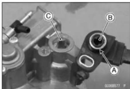
- Install:
O-ring [A]
Carburetor Cap [B]
Bolts (tighten)
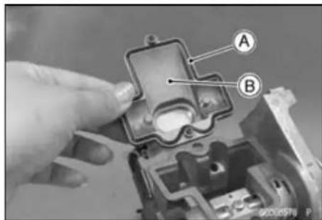
- Install:
Starter Jet [A]
Pilot Jet [B]
Baffle Plate [C]
Needle Jet [D]
Main Jet [E]
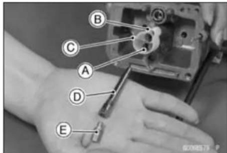
- Replace the O-ring with new one (Australia and Europe models).
• Install (Australia and Europe models):
Pilot Air Screw [A]
Spring [B]
Washer [C]
O-ring [D]
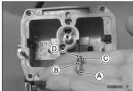
Turn in the pilot air screw fully but not tightly, and the back it out the counted number of turn (see Carburetor Disassembly).
- Hanging the float valve [A] on the tang [B] of the float [C].
- Fit the float valve into the valve seat.
- Insert the pin [D].
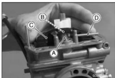
3-26 FUEL SYSTEM
Carburetor
- Install:
Leak Jet [A] - Replace the O-ring with new one.
- Fit the O-ring [B] onto the groove of the float chamber.
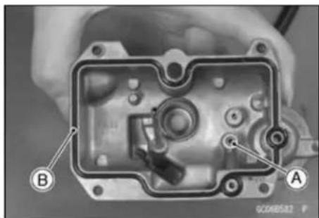
- Install:
Float Bowl - Tighten the screws with hose clamps [A] and cable holder [B] as shown.
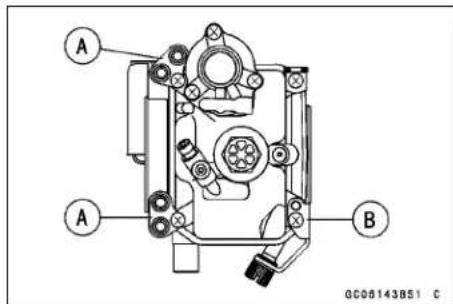
- Replace the O-rings with new ones.
- Fit the O-rings [A].
- Install:
Diaphragm [B]
Spring [C]
Acceleration Pump Cover
○Install the diaphragm so that its mark facing [D] outward.
- Tighten the bolts.
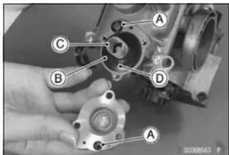
• Install the choke knob/starter plunger [A].
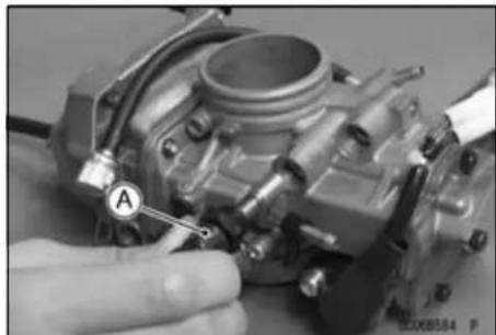
- Replace the O-rings [A] with the new ones.
• Install the fuel hose fitting [B]. - Tighten the screws.
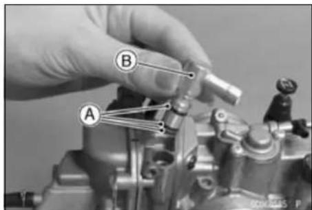
Carburetor
- Install all hoses [A].
• Install the carburetor (see Carburetor Installation).
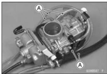
- If turn the adjusting screw of the acceleration pump, follow the procedures below.
○Adjust the acceleration pump timing.
○Select an arbor [A] of the same diameter as the throttle valve height [B] and insert it under the throttle valve.
Throttle Valve Height - 1.25 mm (0.0492 in.)
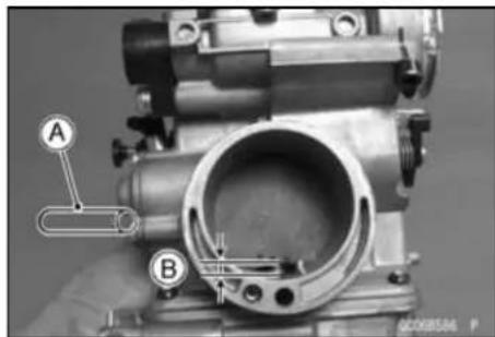
○Turn in the adjusting screw [A] fully.
○Check the push rod holder [B] play.
Turn the adjusting screw counterclockwise gradually to adjust with the push rod holder moving forward or backward till no free play is available.
Push Rod [C]
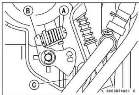
Air Cleaner
Air Cleaner Housing Removal
- Remove:
Side Covers (see Side Cover Removal in the Frame chapter)
Seat (see Seat Removal in the Frame chapter)
Muffler (see Muffler Removal in the Engine Top End chapter)
Rear Fender (see Rear Fender Removal in the Frame chapter)
Rear Frame Bolts [A]
- Remove the hoses [B] from the air cleaner housing.
- Loosen the air cleaner duct clamp [C].
- Remove the rear frame.
- Unscrew the bolts [A].
- Remove the air cleaner housing [B].
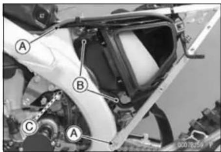
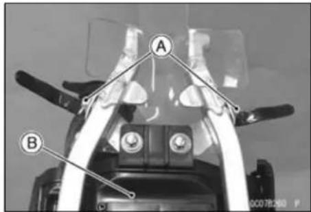
Air Cleaner Housing Installation
- Installation is the reverse of the removal.
- Tighten:
Torque - Rear Frame Mounting Bolts: 34 N·m (3.5 kgf·m, 25 ft·lb)
Element Removal
- Remove:
Screw [A]
Front Left Side Cover [B]
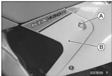
- Remove:
Wing Bolt [A]
Element [B]
- Stuff a clean, lint-free towel into the carburetor so no dirt is allowed to enter the carburetor.
- Wipe out the inside of the air cleaner housing with a clean damp towel.
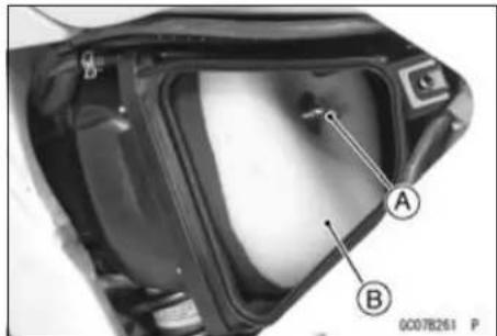
NOTICE
Check inside of the intake tract and carburetor for dirt. If dirt is present, clean the intake tract and carburetor thoroughly. You may also need to replace the element and seal the housing and intake tract.
Air Cleaner
Element Installation
- When installing the element, coat the lip of the element with a thick layer of all purpose grease [A] to assure a complete seal against the air cleaner element base. Also, coat the base where the lip of the element fits.
- Apply grease to all connections and screw holes in the air cleaner housing and intake tract.
- Take out the towel from the carburetor securely.
• Install the element so that its tab [A] faces leftside and fit the frame projections [B] to the holes of the holder [C].
- Tighten the wing bolt [D].
- Install the seat (see Seat Installation in the Frame chapter).
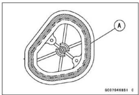
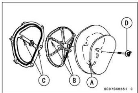
Element Cleaning and Inspection
- Refer to the Air Cleaner Element Cleaning and Inspection in the Periodic Maintenance chapter.
Fuel Tank
Fuel Tank Removal
WARNING
Gasoline is extremely flammable and can be explosive under certain conditions. Always stop the engine and do not smoke. Make sure the area is well-ventilated and free from any source of flame or sparks; this includes any appliance with a pilot light.
- Turn the fuel tap lever [A] to the OFF position.
- Slide out the clamp [B] and pull the fuel hose [C] off the fuel tap [D].
-
Remove the bolt [E].
-
Remove: Seat (see Seat Removal in the Frame chapter) Bolts [A]
- Remove the fuel tank mounting bolt [B] and unhook the band [C].
- Pull out the fuel tank breather hose [D] from the steering stem.
- Remove the fuel tank [E] together with the radiator shrouds.
- Drain the fuel.
Fuel Tank Installation
- Check the rubber dampers [A] on the frame.
★If the dampers are damaged or deteriorated, replace them. - Be sure the fuel hose is clamped to the fuel tap to prevent leaks.
- Insert the fuel tank breather hose outlet end into the steering stem hole.
Fuel Filter Removal
- Remove the fuel tank and drain it (see Fuel Tank Removal).
- Remove the mounting bolts [A] and take out the fuel filter [B].
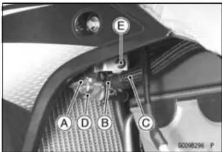
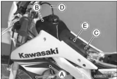
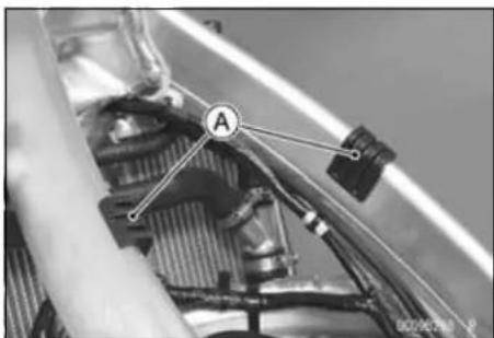
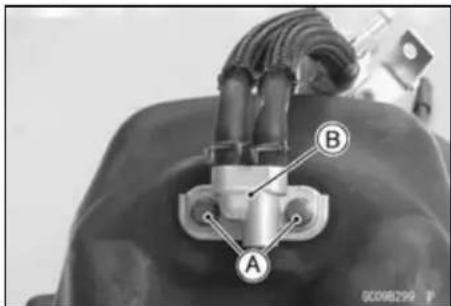
Fuel Filter Installation
- Replace the O-ring with a new one.
- Be sure to clamp the fuel hose to the tap and fuel filter to prevent leaks.
Fuel Tank
Fuel Tank, Filter and Tap Cleaning
- Refer to the Fuel Tank, Filter and Tap Cleaning in the Periodic Maintenance chapter.
Fuel Tap and Filter Inspection
- Refer to the Fuel Tap and Filter Inspection in the Periodic Maintenance chapter.
Cooling System
Table of Contents
Exploded View 4-2
Coolant Flow Chart.... 4-4
Specifications 4-6
Special Tool 4-7
Coolant 4-8
Coolant Level Inspection 4-8
Coolant Deterioration Inspection 4-8
Coolant Draining 4-8
Coolant Filling 4-9
Air Bleeding 4-10
Cooling System Pressure Testing 4-11
Cooling System Flushing 4-11
Reserve Tank Removal 4-12
Water Pump 4-13
Water Pump Cover Removal 4-13
Water Pump Cover Installation 4-13
Impeller Removal 4-14
Impeller Installation 4-14
Water Pump Inspection 4-14
Oil Seal and Bearing Removal 4-14
Oil Seal and Bearing Installation 4-15
Radiator 4-16
Radiator Removal 4-16
Radiator Installation 4-17
Radiator Inspection 4-17
Radiator Cap Inspection 4-17
Filler Neck Inspection.... 4-18
Hose Inspection 4-18
Hose Installation 4-18
4-2 COOLING SYSTEM
Exploded View
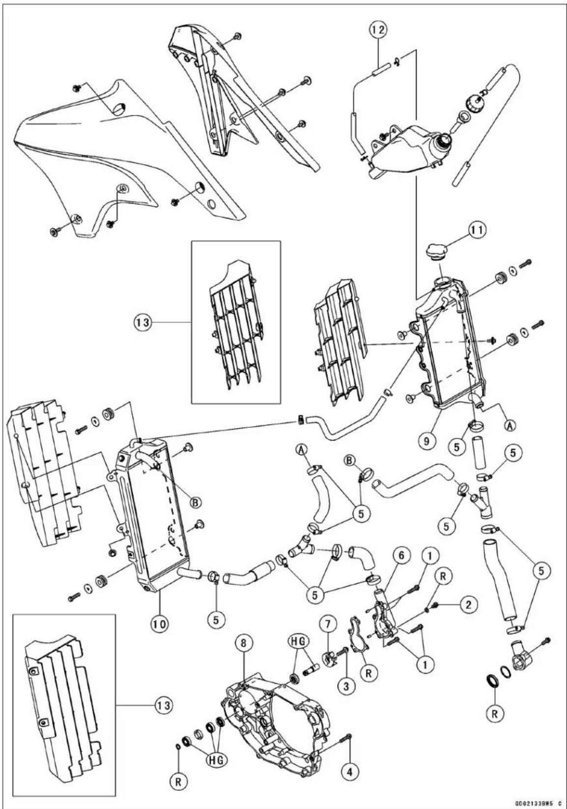
Exploded View
| No. | Fastener | Torque | Remarks | ||
| N·m kgf·m ft·lb | |||||
| 1 | Water Pump Cover Bolts | 9.8 | 1.0 | 87 in·lb | |
| 2 | Coolant Drain Plug | 7.0 | 0.70 | 62 in·lb | |
| 3 | Water Pump Impeller Bolt | 9.8 | 1.0 | 87 in·lb | |
| 4 | Right Engine Cover Bolts | 9.8 | 1.0 | 87 in·lb | |
| 5 | Radiator Hose Clamp Screws | 3.0 | 0.30 | 27 in·lb | |
- Water Pump Cover
- Impeller
- Right Engine Cover
- Right Radiator
- Left Radiator
- Radiator Cap
- Reserve Tank Hose
- KLX450A9F Model \~
HG: Apply high-temperature grease.
R: Replacement Parts
4-4 COOLING SYSTEM
Coolant Flow Chart
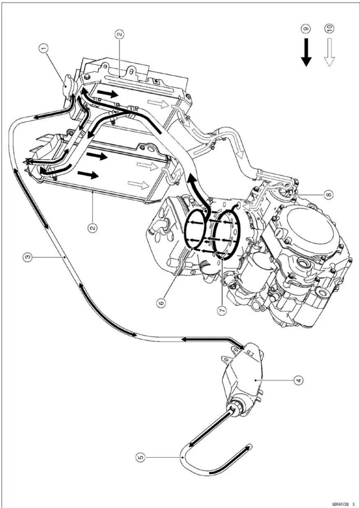
Coolant Flow Chart
- Radiator Cap
- Radiators
- Reserve Tank Hose
- Reserve Tank
- Reserve Tank Over Flow Hose
- Cylinder Head Jacket
- Cylinder Jacket
- Impeller
- Hot Coolant
- Cold Coolant
Permanent type antifreeze is used as a coolant to protect the cooling system from rust and corrosion. When the engine starts, the water pump turns and the coolant circulates.
The system is pressurized by the radiator cap to suppress boiling and the resultant air bubbles which can cause engine overheating. As the engine warms up, the coolant in the radiator and the water jacket expands. The excess coolant flows through the radiator cap and hose to the reserve tank to be stored there temporarily. Conversely, as the engine cools down, the coolant in the radiator and the water jacket contracts, and the stored coolant flows back to the radiator from the reserve tank.
The radiator cap has two valves. One is a pressure valve which holds the pressure in the system when the engine is running. When the pressure exceeds 112.3 \~ 141.7 kPa (1.145 \~ 1.445 kgf/cm², 16.28 \~ 20.55 psi), the pressure valve opens and releases the pressure to the reserve tank. As soon as pressure escapes, the valve closes, and keeps the pressure at 112.3 \~ 141.7 kPa (1.145 \~ 1.445 kgf/cm², 16.28 \~ 20.55 psi). When the engine cools down, another small valve (vacuum valve) in the cap opens. As the coolant cools, the coolant contracts to form a vacuum in the system. The vacuum valve opens and allows the coolant from the reserve tank to enter the radiator.
4-6 COOLING SYSTEM
Specifications
| Item Service Limit | |
| CoolantTypeColor GreenMixed Ratio Soft water 50% Freezing Point -35°C (-31°F)Total Amount 1.05 L (1.11 US qt.) | Permanent type antifreeze (soft water and ethylene glycol plus corrosion and rust inhibitor chemicals for aluminum engines and radiators)coolant 50% |
| RadiatorCap Relief Pressure | 112.3 ~ 141.7 kPa (1.145 ~ 1.445 kgf/cm2, 16.28 ~ 20.55 psi) |
Special Tool
Bearing Driver Set:
57001-1129
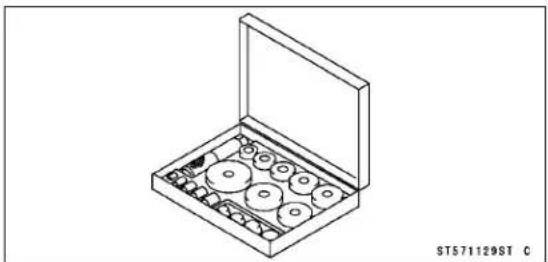
4-8 COOLING SYSTEM
Coolant
Check the coolant level each day before riding the motorcycle, and replenish coolant if the level is low. Change the coolant in accordance with the Periodic Maintenance Chart (see Periodic Maintenance chapter).
WARNING
Hot engine coolant can cause serious burns. To avoid burns, do not remove the radiator cap or try to inspect the coolant level or change the coolant when the engine is still hot. Wait until it cools down.
Coolant Level Inspection
- Refer to the Coolant Level Inspection in the Periodic Maintenance chapter.
Coolant Deterioration Inspection
- Refer to the Coolant Deterioration Inspection in the Periodic Maintenance chapter.
Coolant Draining
- The coolant should be changed periodically to ensure long engine life.
WARNING
Coolant can be extremely hot and cause severe burns, is toxic and very slippery. Do not remove the radiator cap or attempt to change the coolant when the engine is hot; allow it cool completely. Immediately wipe any spilled coolant from tires, frame, engine or other painted parts. Do not ingest coolant.
- Remove the radiator cap [A].
NOTE
○ Remove the radiator cap in two steps. First turn the cap counterclockwise to the first stop and wait there for a few seconds. Then push down and turn it further in the same direction and remove the cap.
- Remove: Bolt [A] Engine Guard [B]
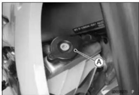
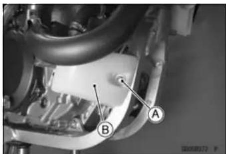
Coolant
- Place a container under the coolant drain plug [A], and drain the coolant from the radiator and engine by removing the drain plug on the water pump cover. Immediately wipe or wash out any coolant that spills on the frame, or engine.
- Inspect the old coolant for visual evidence of corrosion and abnormal smell (see Coolant Deterioration Inspection in the Periodic Maintenance chapter).
- Remove:
Bolts [A]
Reserve Tank Cap [B]
- Turn over the reserve tank, and pour the coolant into the suitable container.
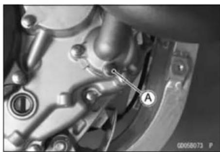
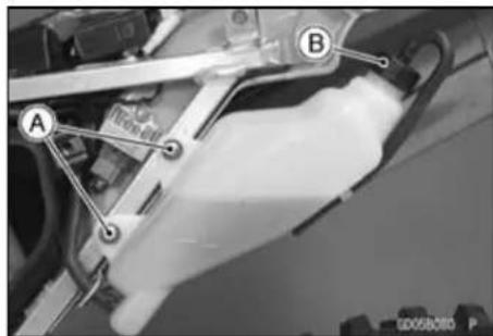
Coolant Filling
NOTICE
Use coolant containing corrosion inhibitors made specifically for aluminum engines and radiators in accordance with the instruction of the manufacture's. Soft or distilled water must be used with the antifreeze (see below for antifreeze) in the cooling system. If hard water is used in the system, it causes scale accumulation in the water passages, and considerably reduces the efficiency of the cooling system.
Recommended Coolant
| Type: | Permanent type antifreeze (soft water and ethylene glycol plus corrosion and rust inhibitor chemicals for aluminum engines and radiators) |
| Color: | Green |
| Mixed ratio: | Soft water 50%, Coolant 50% |
| Freezing point: | -35°C (-31°F) |
| Total amount | 1.05 L (1.11 US qt.) |
- Install the drain plug.
○Replace the gasket with a new one.
Torque - Coolant Drain Plug: 7.0 N·m (0.70 kgf·m, 62 in·lb)
Coolant
- Fill the radiator up to the bottom of the radiator filler neck [B] with coolant [A], and install the cap, turning it clockwise about 1/4 turn.
○Lean the motorcycle slightly to the right until the radiator filler neck is level to the ground so that the filler neck is located uppermost in order to exhaust the air accumulated in the radiator.
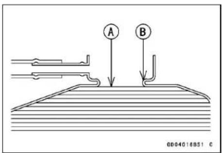
NOTE
Pour in the coolant slowly so that it can expel the air from the engine and radiator. The radiator cap must be installed into two steps. First turn the cap clock wiseto the first stop. Then push down on it and turn it the rest of the way.
- Check the cooling system for leaks.
- Fill the reserve tank up to the "F" (full) level line [A] with coolant and install the cap.
- Start the engine and warm it up thoroughly.
- Check the coolant level in the reserve tank several times while the engine is cooling down, and replenish as necessary.
★If the coolant level is lower than the "L" level line [B], add coolant to the "F" level line.
NOTICE
Do not add more coolant above the "F" level line.
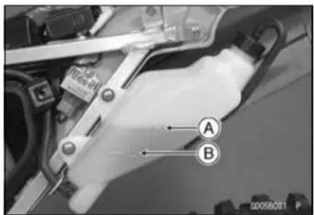
Air Bleeding
Before putting the motorcycle into operation, any air trapped in the cooling system must be removed as follows.
- Start the engine, warm up the engine thoroughly, and then stop the engine. Wait until the engine cools down.
- Remove the radiator cap.
- Check the coolant level (see Coolant Level Inspection in the Periodic Maintenance chapter).
★If the coolant level is low, add coolant up to the bottom of the filler neck.
• Install the radiator cap. - Check the cooling system for leaks.
Coolant
Cooling System Pressure Testing
NOTICE
During pressure testing, do not exceed the pressure for which the system is designed to work. The maximum pressure is 141.7 kPa (1.445 kgf/cm 2 , 20.55 psi).
- Remove the radiator cap, and install a cooling system pressure tester [A] and adapter [B] on the radiator filler neck [C].
NOTE
○ Wet the adapter cap sealing surfaces with water or coolant to prevent pressure leaks.
- Build up pressure in the system carefully until the pressure reaches 141.7 kPa (1.445 kgf/cm², 20.55 psi).
- Watch the gauge for at least 6 seconds. If the pressure holds steady, the cooling system is all right.
- Remove the pressure tester, replenish the coolant, and install the radiator cap.
★If the pressure drops and no external source is found, check for internal leaks. Check the cylinder head gasket for leaks.
Cooling System Flushing
Over a period of time, the cooling system accumulates rust, scale, and lime in the water jacket and radiator. When this accumulation is suspected or observed, flush the cooling system. If this accumulation is not removed, it will clog up the water passages and considerably reduce the efficiency of the cooling system.
- Drain the cooling system.
- Fill the cooling system with fresh water mixed with a flushing compound.
NOTICE
Avoid the use of a flushing compound which is harmful to the aluminum engine and radiator. Carefully follow the instructions supplied by the manufacture of the cleaning product.
- Warm up the engine, and run it at normal operating temperature for about ten minutes.
- Stop the engine, and drain the cooling system after the coolant cools down.
- Fill the system with fresh water.
- Warm up the engine and drain the system after the coolant cools down.
- Repeat the previous two steps once more.
- Fill the system with a permanent type coolant, and bleed the air from the system (see Air Bleeding).
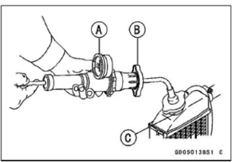
4-12 COOLING SYSTEM
Coolant
Reserve Tank Removal
- Remove: Seat (see Seat Removal in the Frame chapter) Left Side Cover (see Left Side Cover Removal in the Frame chapter)
- Remove: Bolts [A] Cap [B]
- Drain the coolant to the suitable container.
- Remove: Hose [C]
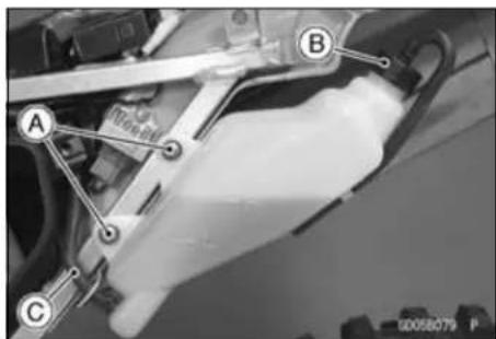
Water Pump
Water Pump Cover Removal
- Remove engine guard (see Coolant Draining).
- Unscrew the drain plug [A], and drain the coolant (see Coolant Draining).
- Loosen the clamp screw [B], and remove the water hose [C] from the water pump cover.
- Unscrew the cover bolts [D].
- Using the pry points [A], remove the pump cover [B].
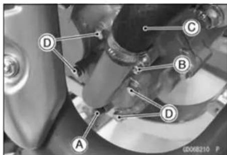
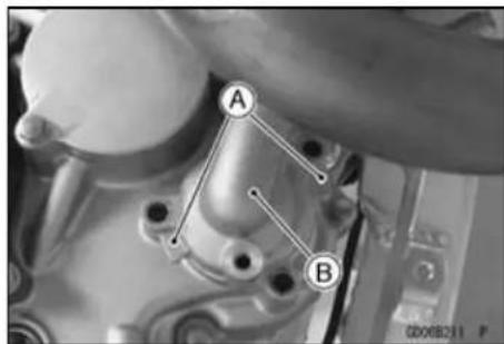
Water Pump Cover Installation
- Replace the pump cover gasket [A] with a new one.
- Check to see that the dowel pins [B] are in place in the mating surfaces of the right engine cover.
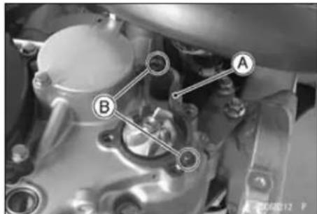
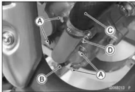
- Install the water pump cover.
○Replace the drain plug gasket with a new one. - Tighten:
Torque - Water Pump Cover Bolts [A]: 9.8 N·m (1.0 kgf·m, 87 in·lb)
Coolant Drain Plug [B]: 7.0 N·m (0.70 kgf·m, 62 in·lb)
- Insert the water hose [C] into the water pump cover.
- Tighten:
Torque - Radiator Hose Clamp Screws [D]: 3.0 N·m (0.30 kgf·m, 27 in·lb)
- Fill the cooling system (see Coolant Filling).
- Bleed the air from the cooling system.
- Check the coolant level and add the coolant.
4-14 COOLING SYSTEM
Water Pump
Impeller Removal
- Drain: Coolant (see Coolant Draining)
- Remove: Water Pump Cover (see Water Pump Cover Removal) Impeller Bolt [A] Impeller [B]
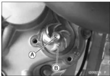
Impeller Installation
- Install: Impeller [A]
- Tighten:
Torque - Water Pump Impeller Bolt [B]: 9.8 N·m (1.0 kgf·m, 87 in·lb)
• Install: Water Pump Cover (see Water Pump Cover Installation)
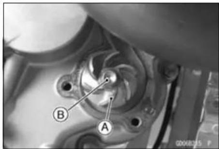
Water Pump Inspection
- Visually check the impeller [A].
★If the surface is corroded, or if the blades [B] are damaged, replace the impeller.
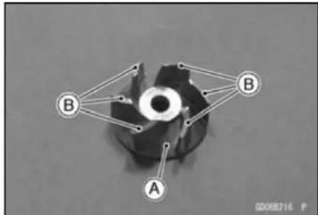
- Check the drainage outlet passage [A] at the bottom of the right engine cover for coolant leaks.
★If the oil seal is damaged, the coolant leaks through the seal and drains through the passage. Replace the oil seals.
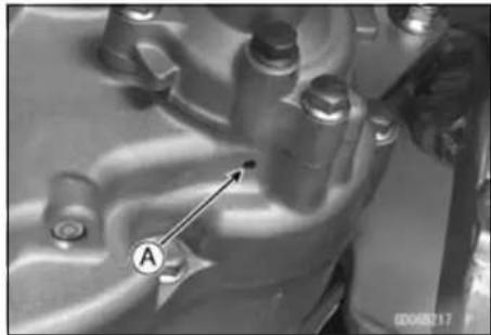
Oil Seal and Bearing Removal
- Remove: Impeller (see Impeller Removal) Right Engine Cover (see Right Engine Cover Removal in the Engine Right Side chapter) Circlip [A] Water Pump Shaft [B]
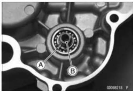
Water Pump
- Insert a bar [A] into the water pump shaft hole from the outside of the right engine cover, and remove the ball bearing [B] by tapping [C] evenly around the bearing inner race.
- Remove the spacer [D].
- Remove the ball bearing [E] and oil seal [F] from the right engine cover in the same way as ball bearing removal.
- Insert a bar [A] into the water pump shaft hole from the inside of the right engine cover, and remove the oil seal [B] by tapping [C] evenly around the seal lips.
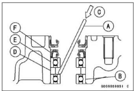
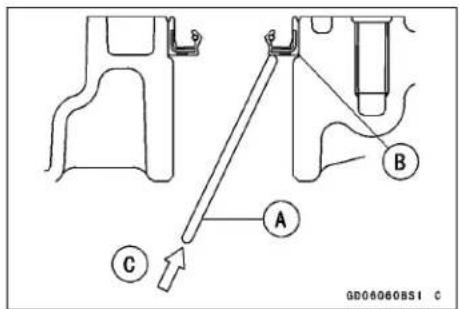
Oil Seal and Bearing Installation
NOTICE
If the oil seal or ball bearing is removed, replace all of them with new ones at the same time
- Be sure to replace the oil seals.
- Apply plenty of high-temperature grease to the oil seal lips.
- Press in the new oil seal [A] using a bearing driver set from the outside of the right engine cover so that the seal bottom surface is flush with the end face [B] of the right engine cover.
- Press in the new oil seal [C] using a bearing driver set from the outside of the right engine cover so that the oil seal surface is flush [D] with the surface of the right engine cover.
Special Tool - Bearing Driver Set: 57001-1129
- Press the ball bearings [A] together with the spacer [B] into the hole until the face of the bearing is even [C] with the end of the hole.
Special Tool - Bearing Driver Set: 57001-1129
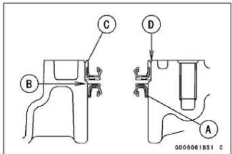
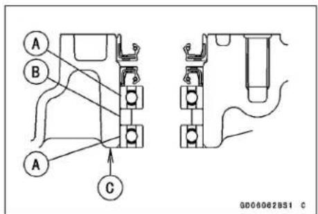
4-16 COOLING SYSTEM
Radiator
Radiator Removal
- Drain the coolant (see Coolant Draining)
- Remove: Radiator Shrouds
- Loosen: Clamp Screws [A] Clamps [B]
- Remove: Radiator Hoses [C] Bolt [D] Left Radiator Screen [E]
- Remove: Bolts [A] Left Radiator [B]
- Loosen: Clamp Screws [A] - Remove: Radiator Hoses [B] Bolt [C] Right Radiator Screen [D]
- Remove: Bolts [A] Right Radiator [B]
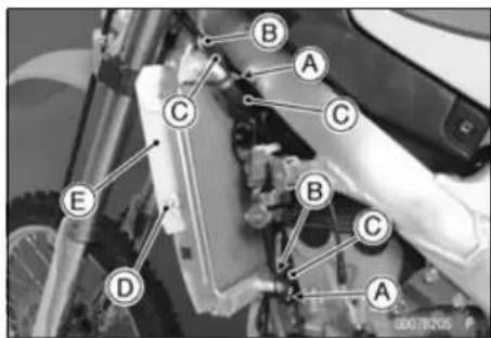
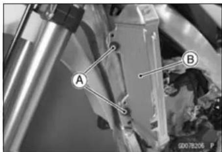
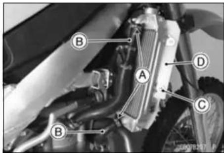
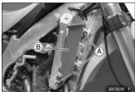
Radiator
Radiator Installation
- Fit the projections [A] of the screen in the holes [B] of the radiator.
Torque - Radiator Hose Clamp Screws: 3.0 N·m (0.30 kgf·m, 27 in·lb) - Route the radiator and breather hoses correctly (see Cable, Wire, and Hose Routing section in the Appendix chapter).
- Fill the cooling system with a permanent type coolant.
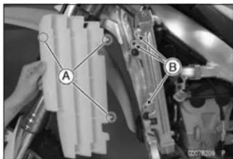
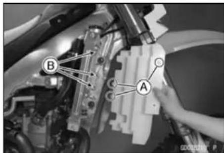
Radiator Inspection
- Check the radiator core.
★If there are obstructions to air flow, remove them.
★If the corrugated fins are deformed, carefully straighten them with the thin blade of a screwdriver [A].
NOTICE
Do not tear the radiator tubes while straightening the fins.
★If the air passages of the radiator core are blocked more than 20% by unremovable obstructions or irreparably deformed fins, replace the radiator with a new one.
NOTICE
When cleaning the radiator with steam cleaner, be careful of the following to prevent radiator damage. Keep the steam gun [A] away more than 0.5 m (1.64 ft) [B] from the radiator core. Hold the steam gun perpendicular to the core surface. Run the steam gun following the core fin direction [C].
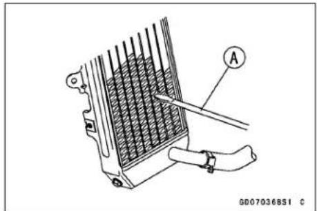
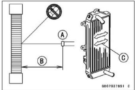
Radiator Cap Inspection
- Check the condition of the valve seals [A], and the top and bottom valve spring [B] of the radiator cap.
★If any one of them shows visible damage, replace the cap.
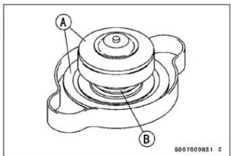
4-18 COOLING SYSTEM
Radiator
- Wet the top and bottom valve seals with water or coolant to prevent pressure leaks.
- Install the cap [A] on a cooling system pressure tester [B].
- Watching the pressure gauge, slowly pump the pressure tester to build up the pressure. The gauge hand must remain within the relief pressure range in the table below at least 6 seconds. Continue to pump the tester until the relief valve opens, indicated by the gauge hand flicking downward. The relief valve must open within the specified range.
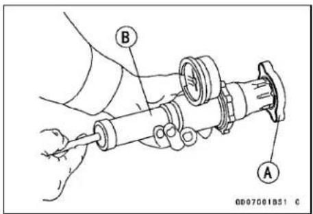
Radiator Cap Relief Pressure
Standard: 112.3 \~ 141.7 kPa (1.145 \~ 1.445 kgf/cm², 16.28 \~ 20.55 psi)
★If the cap cannot hold the pressure, or if the relief pressure is too high or too low, replace the cap with a new one.
Filler Neck Inspection
- Check the radiator filler neck for signs of damage.
- Check the condition of the top and bottom sealing seats [A] in the filler neck. They must be smooth and clean for the radiator cap to function properly.
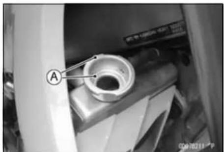
Hose Inspection
- Refer to the Radiator Hoses and Connections Inspection in the Periodic Maintenance chapter.
Hose Installation
- Install the hoses being careful to follow the performed bends (see Cable, Wire, and Hose Routing section in the Appendix chapter). Avoid sharp bending, kinking, flattening, or twisting.
- Tighten the hose clamps securely.
Torque - Radiator Hose Clamp Screws: 3.0 N·m (0.30 kgf·m, 27 in·lb)
Engine Top End
Table of Contents
Exploded View.... 5-2
Specifications 5-6
Special Tools and Sealant.... 5-9
Clean Air System (U.S.A., California, and Canada Models) 5-12
Vacuum Switch Valve Removal ... 5-13
Vacuum Switch Valve Installation 5-13
Cylinder Head Cover 5-14
Cylinder Head Cover Removal .... 5-14
Cylinder Head Cover Installation. 5-14
Camshaft Chain Tensioner 5-15
Camshaft Chain Tensioner Removal.... 5-15
Camshaft Chain Tensioner Installation.... 5-15
Camshaft 5-17
Camshaft Removal 5-17
Camshaft Installation 5-18
Camshaft Chain Removal...... 5-20
Camshaft Chain Installation...... 5-20
Camshaft and Camshaft Cap Wear.... 5-21
Camshaft Runout 5-21
Cam Wear 5-21
Cylinder Head.... 5-22
Cylinder Compression Measurement 5-22
Cylinder Head Removal 5-23
Cylinder Head Installation...... 5-24
Cylinder Head Cleaning 5-25
Cylinder Head Warp.... 5-25
Valves.... 5-26
Valve Clearance Inspection ..... 5-26
Valve Removal.... 5-26
Valve Installation 5-26
Valve Guide Removal 5-27
Valve Guide Installation 5-27
Valve/Valve Guide Clearance Measurement (Wobble Method) 5-28
Valve Seat Inspection 5-29
Valve Seat Repair 5-29
Cylinder and Piston 5-34
Cylinder Removal 5-34
Piston Removal 5-34
Cylinder and Piston Installation.... 5-34
Cylinder Wear 5-36
Piston Wear 5-36
Piston/Cylinder Clearance 5-36
Piston Ring/Ring Groove Clearance 5-36
Piston Ring Groove Width.... 5-37
Piston Ring Thickness 5-37
Piston Ring End Gap Measurement.... 5-37
Piston, Piston Pin, Connecting Rod Wear Inspection.... 5-38
Carburetor Holder 5-39
Carburetor Holder Installation..... 5-39
Muffler.... 5-40
Muffler Removal 5-40
Muffler Installation.... 5-40
Spark Arrester Cleaning.... 5-40
Exhaust System Inspection...... 5-41
5-2 ENGINE TOP END
Exploded View
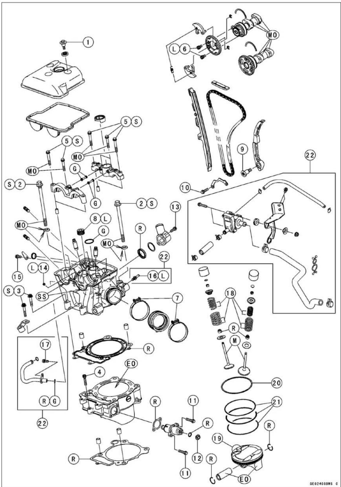
Exploded View
| No. | Fastener | Torque | Remarks | ||
| N·m | kgf·m ft·lb | ||||
| 1 | Cylinder Head Cover Bolts | 9.8 | 1.0 | 87 in·lb | |
| 2 | Cylinder Head Bolts (M10) | 59 | 6.0 | 44 | S, MO |
| 3 | Cylinder Head Bolts (M6) | 12 | 1.2 | 106 in·lb | S |
| 4 | Cylinder Bolt | 12 | 1.2 | 106 in·lb | |
| 5 | Camshaft Cap Bolts | 9.8 | 1.0 | 87 in·lb | S, MO |
| 6 | Camshaft Sprocket Bolts | 12 | 1.2 | 106 in·lb | L |
| 7 | Carburetor Holder Clamp Screws | 2.0 | 0.20 | 18 in·lb | |
| 8 | Plug | 20 | 2.0 | 15 | L |
| 9 | Rear Camshaft Chain Guide Bolt | 15 | 1.5 | 11 | |
| 10 | Oil Pump (Scavenge) Cover Bolts | 9.8 | 1.0 | 87 in·lb | |
| 11 | Chain Tensioner Mounting Bolts | 9.8 | 1.0 | 87 in·lb | |
| 12 | Chain Tensioner Cap Bolt | 5.0 | 0.51 | 44 in·lb | |
| 13 | Water Hose Fitting Bolts | 9.8 | 1.0 | 87 in·lb | |
| 14 | Oil Line Plug | 3.0 | 0.31 | 27 in·lb | L |
| 15 | Decompressor Plug Plate Bolt | 9.8 | 1.0 | 87 in·lb | |
| 16 | Vacuum Hose Fitting | 8.8 | 0.90 | 78 in·lb | L |
| 17 | Cylinder Head Pipe Mounting Bolt | 9.8 | 1.0 | 87 in·lb | |
- Closed coil end faces down.
- Circle Mark
- Top Ring
- Oil Ring
- U.S.A., California, and Canada Models
EO: Apply engine oil.
G: Apply grease.
L: Apply a non-permanent locking agent.
M: Apply molybdenum disulfide grease.
MO: Apply molybdenum disulfide oil.
R: Replacement Parts
S: Follow the specific tightening sequence.
SS: Apply silicon sealant.
5-4 ENGINE TOP END
Exploded View
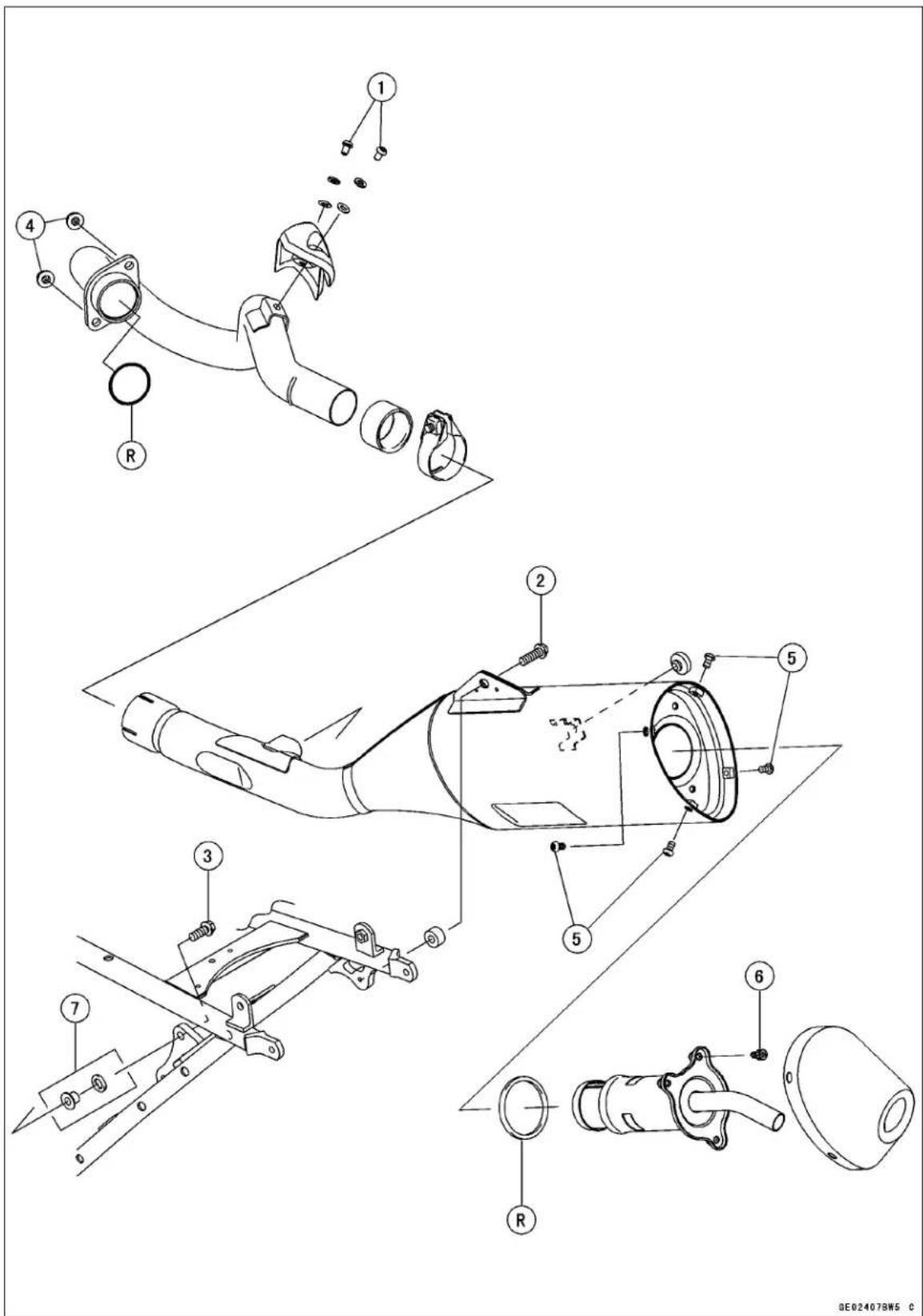
Exploded View
| No. | Fastener | Torque | Remarks | ||
| N·m | kgf·m ft·lb | ||||
| 1 | Exhaust Pipe Cover Bolts | 12 | 1.2 | 106 in·lb | |
| 2 | Rear Muffler Mounting Bolt | 20 | 2.0 | 15 | |
| 3 | Front Muffler Mounting Bolt (First) | 9.8 | 1.0 | 87 in·lb | |
| Front Muffler Mounting Bolt (Final) | 20 | 2.0 | 15 | ||
| 4 | Exhaust Pipe Holder Nuts | 20 | 2.0 | 15 | |
| 5 | Muffler End Mounting Bolts | 10 | 1.0 | 89 in·lb | |
| 6 | Spark Arrester Mounting Bolts | 10 | 1.0 | 89 in·lb | |
- KLX450A8F Model
R: Replacement Parts
Specifications
| Item Standard Service Limit | ||
| Camshafts | ||
| Cam Height: | ||
| Exhaust | 36.443 ~ 36.557 mm (1.4348 ~ 1.4392 in.) | 36.34 mm (1.431 in.) |
| Intake | 37.143 ~ 37.257 mm (1.4623 ~ 1.4668 in.) | 37.04 mm (1.458 in.) |
| Camshaft Journal, Camshaft Cap Clearance | 0.020 ~ 0.061 mm (0.00079 ~ 0.0024 in.) | 0.15 mm (0.0059 in.) |
| Camshaft Journal Diameter | 22.959 ~ 22.980 mm (0.90390 ~ 0.90472 in.) | 22.93 mm (0.9028 in.) |
| Camshaft Journal Inside Diameter | 23.000 ~ 23.020 mm (0.90551 ~ 0.90630 in.) | 23.08 mm (0.9087 in.) |
| Camshaft Runout | TIR 0.02 mm (0.0008 in.) or less | TIR 0.1 mm (0.004 in.) |
| Cylinder Head | ||
| Cylinder Compression: | ||
| Kick Starter | (Usable range) 450 ~ 750 kPa (4.59 ~ 7.65 kg/cm2, 65.2 ~ 109 psi) @ 5 kicks. | - - - |
| Electric Starter | (Usable range) 450 ~ 750 kPa (4.59 ~ 7.65 kg/cm2, 65.2 ~ 109 psi) @ 420 r/min (rpm) | - - - |
| Cylinder Head Warp | - - - | 0.05 mm (0.002 in.) |
| Valve | ||
| Valve Clearance: | ||
| Exhaust | 0.20 ~ 0.25 mm (0.0079 ~ 0.0098 in.) | - - - |
| Intake | 0.10 ~ 0.15 mm (0.0039 ~ 0.0059 in.) | - - - |
| Valve Stem Bend | TIR 0.01 mm (0.0004 in.) or less | TIR 0.05 mm (0.002 in.) |
| Valve Stem Diameter: | ||
| Exhaust | 5.455 ~ 5.470 mm (0.2148 ~ 0.2154 in.) | 5.44 mm (0.214 in.) |
| Intake | 5.465 ~ 5.480 mm (0.2152 ~ 0.2157 in.) | 5.45 mm (0.215 in.) |
| Valve Guide Inside Diameter: | ||
| Exhaust | 5.500 ~ 5.512 mm (0.2165 ~ 0.2170 in.) | 5.58 mm (0.220 in.) |
| Intake | 5.500 ~ 5.512 mm (0.2165 ~ 0.2170 in.) | 5.58 mm (0.220 in.) |
| Valve/valve Guide Clearance (wobble method): | ||
| Exhaust | 0.09 ~ 0.16 mm (0.0035 ~ 0.0063 in.) | 0.36 mm (0.014 in.) |
| Intake | 0.06 ~ 0.14 mm (0.0024 ~ 0.0055 in.) | 0.33 mm (0.013 in.) |
| Valve Seat Cutting Angle | 45°, 32°, 60° | - - - |
| Valve Seating Surface Outside Diameter: | ||
| Exhaust | 29.4 ~ 29.6 mm (1.16 ~ 1.17 in.) | - - - |
| Intake | 34.4 ~ 34.6 mm (1.35 ~ 1.36 in.) | - - - |
| Valve Seating Surface Width: | ||
| Exhaust | 0.8 ~ 1.2 mm (0.03 ~ 0.047 in.) | - - - |
| Intake | 0.5 ~ 1.0 mm (0.02 ~ 0.039 in.) | - - - |
Specifications
| Item Standard Service Limit | ||
| Valve Spring Free Length: | ||
| Exhaust: | ||
| Outer | 36.2 mm (1.43 in.) | 34.6 mm (1.36 in.) |
| Intake | 32.4 mm (1.28 in.) | 30.9 mm (1.22 in.) |
| Intake: | ||
| Outer | 39.3 mm (1.55 in.) | 37.8 mm (1.49 in.) |
| Inner | 36.0 mm (1.42 in.) | 34.5 mm (1.36 in.) |
| Cylinder and Pistons | ||
| Cylinder Inside Diameter | 96.000 ~ 96.012 mm (3.7795 ~ 3.7800 in.) | 96.10 mm (3.783 in.) |
| Piston Diameter | 95.970 ~ 95.980 mm (3.7783 ~ 3.7787 in.) | 95.82 mm (3.772 in.) |
| Piston/Cylinder Clearance | 0.020 ~ 0.042 mm (0.00079 ~ 0.0017 in.) | -- -- |
| Piston Ring/Ring Groove Clearance: | ||
| Top | 0.04 ~ 0.08 mm (0.002 ~ 0.003 in.) | 0.18 mm (0.0071 in.) |
| Piston Ring Groove Width: | ||
| Top | 1.03 ~ 1.05 mm (0.0406 ~ 0.0413 in.) | 1.13 mm (0.0445 in.) |
| Piston Ring Thickness: | ||
| Top | 0.970 ~ 0.990 mm (0.0382 ~ 0.0390 in.) | 0.90 mm (0.035 in.) |
| Piston Ring End Gap: | ||
| Top | 0.25 ~ 0.35 mm (0.0098 ~ 0.014 in.) | 0.6 mm (0.02 in.) |
| Oil | 0.15 ~ 0.50 mm (0.0059 ~ 0.020 in.) | 0.8 mm (0.03 in.) |
| Piston Pin Diameter | 18.991 ~ 19.000 mm (0.74768 ~ 0.74803 in.) | 18.96 mm (0.7465 in.) |
| Piston Pin Hole Diameter | 19.004 ~ 19.010 mm (0.74819 ~ 0.74842 in.) | 19.08 mm (0.7512 in.) |
| Connecting Rod Small End Inside Diameter | 19.019 ~ 19.030 mm (0.74878 ~ 0.74921 in.) | 19.07 mm (0.7508 in.) |
TIR: Total Indicator Readings.
5-8 ENGINE TOP END
Specifications
Cam Height
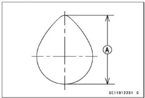
Cam Height [A]
Camshaft Runout
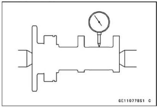
Valve Stem Diameter
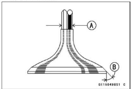
Valve Stem Diameter [A] 45° [B]
Valve Stem Bend
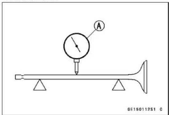
Dial Gauge [A]
Special Tools and Sealant
Compression Gauge, 20 kgf/cm²: 57001-221
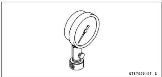
Valve Spring Compressor Assembly: 57001-241
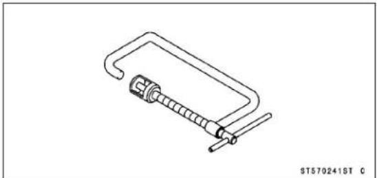
Valve Guide Arbor, 5.5: 57001-1021
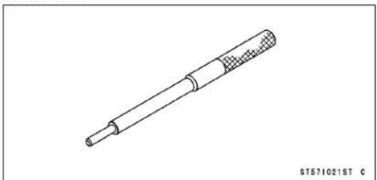
Valve Guide Reamer, 5.5: 57001-1079
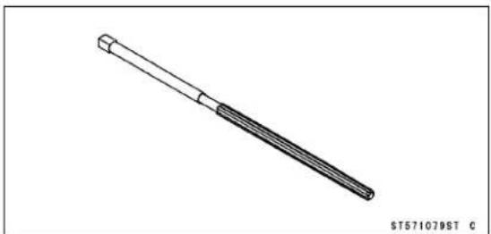
Piston Ring Compressor Grip: 57001-1095
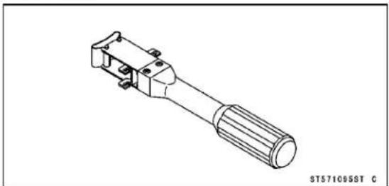
Valve Seat Cutter, 45° - 25: 57001-1116
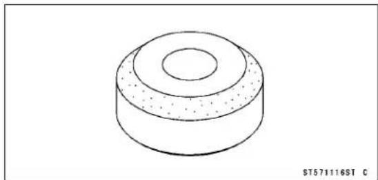
Valve Seat Cutter, 32° - 25: 57001-1121
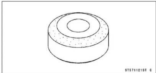
Valve Seat Cutter, 32° - 38.5: 57001-1122
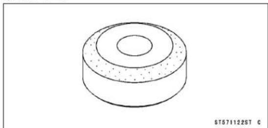
Valve Seat Cutter Holder, 5.5: 57001-1125
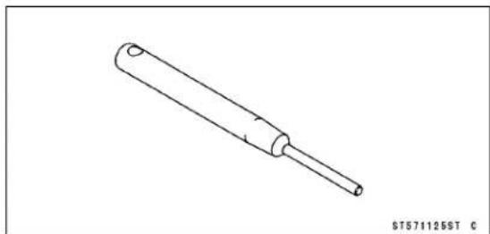
Valve Seat Cutter Holder Bar: 57001-1128
5-10 ENGINE TOP END
Special Tools and Sealant
Valve Seat Cutter, 55° - 35: 57001-1247
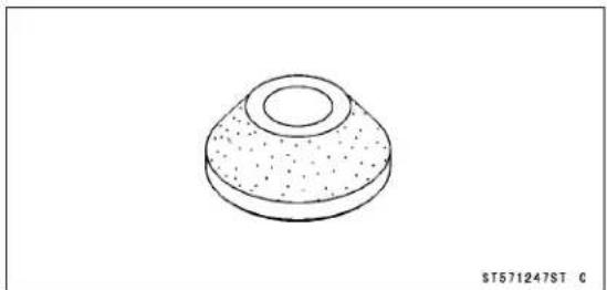
Spark Plug Wrench, Hex 16: 57001-1262
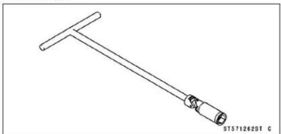
Fork Oil Level Gauge: 57001-1290
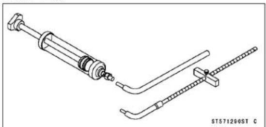
Compression Gauge Adapter, M10 × 1.0: 57001-1317
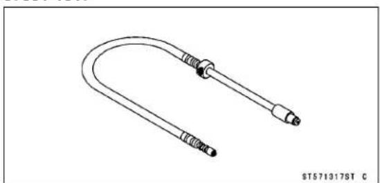
Piston Ring Compressor Belt, φ 95 φ 108: 57001-1358
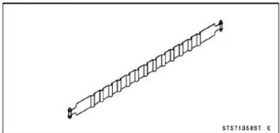
Filler Cap Driver: 57001-1454
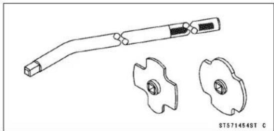
Valve Seat Cutter, 45° - 40: 57001-1496
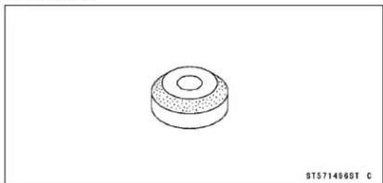
Valve Seat Cutter, 55° - 38.5: 57001-1497
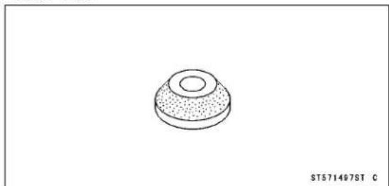
Valve Guide Driver: 57001-1564

Piston Pin Puller: 57001-1568
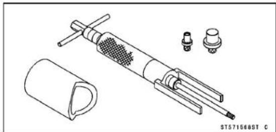
Special Tools and Sealant
Valve Spring Compressor Adapter, 24: 57001-1586
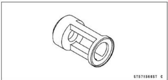
Valve Guide Driver Attachment D: 57001-1659
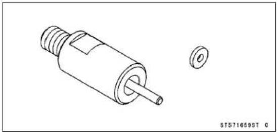
Liquid Gasket, TB1216B: 92104-1064
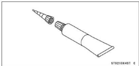
5-12 ENGINE TOP END
Clean Air System (U.S.A., California, and Canada Models)
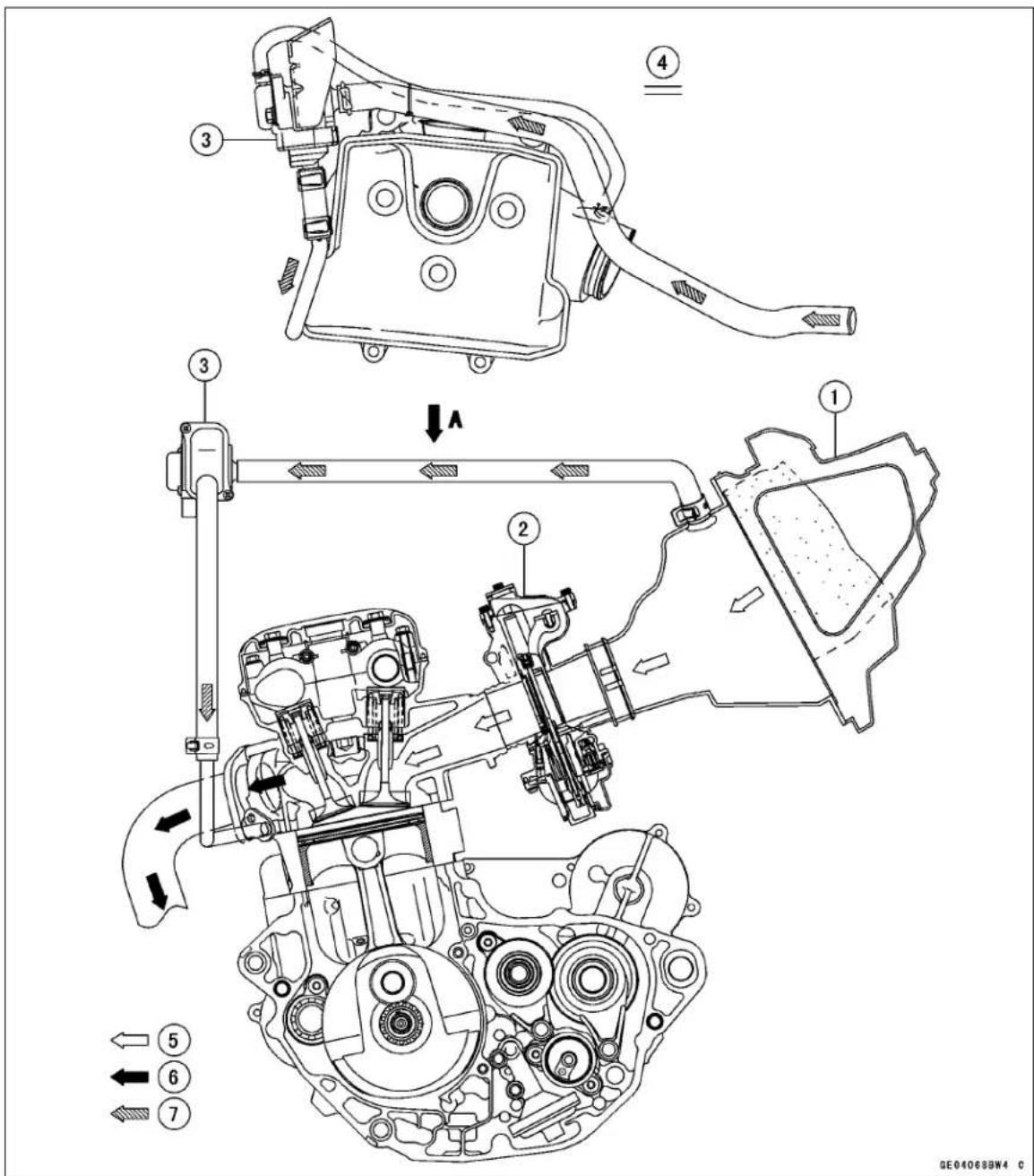
- Air Cleaner
- Carburetor
- Vacuum Switch Valve
- View from A
- Intake Air
- Exhaust Gas
- Secondary Air
Clean Air System (U.S.A., California, and Canada Models)
Vacuum Switch Valve Removal
- Remove:
Fuel Tank (see Fuel Tank Removal in the Fuel System chapter) - Slide out the clamp [A].
- Remove the hose [B] from the cylinder head pipe [C].
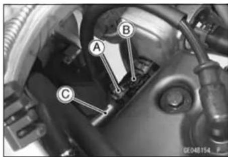
- Slide out the clamps [A] and take off the hoses [B] from the vacuum switch valve.
- Remove the bolts[C] and take off the vacuum switchvalve [D].
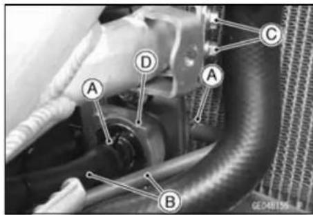
Vacuum Switch Valve Installation
- Installation is the reverse of removal.
5-14 ENGINE TOP END
Cylinder Head Cover
Cylinder Head Cover Removal
- Remove:
Fuel Tank (see Fuel Tank Removal in the Fuel System chapter) Spark Plug Cap - Remove the cylinder head cover bolts [A] and remove the cylinder head cover [B].
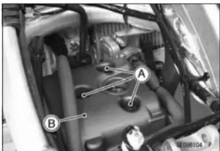
Cylinder Head Cover Installation
- Wipe off any oil, dirt, and dust from the cylinder head matching surface.
- Apply silicon sealant [A] to the cylinder head as shown. Sealant - Liquid Gasket, TB1216B: 92104-1064
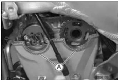
- Replace the head cover gasket.
• Install the head cover gasket [A] on the cylinder head.
• Install the spark plug hole gasket [B].
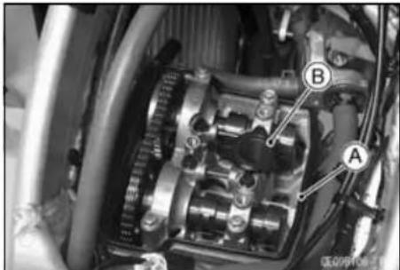
- Make sure that the upper chain guide [A] is bottomed.
NOTICE
Unless the upper chain guide is bottomed, the camshaft chain could push the cylinder head cover upward, leading to an oil leak.
• Install the head cover from the motorcycle left side.
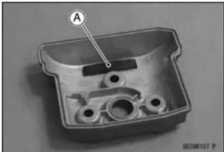
- Install the head cover bolt washers [A] with the metal side upwards.
- Tighten the cover bolt [B].
Torque - Cylinder Head Cover Bolts: 9.8 N·m (1.0 kgf·m, 87 in·lb)
- Install the spark plug cap. ○Pull up the spark plug cap lightly to make sure of the installation of the spark plug cap.
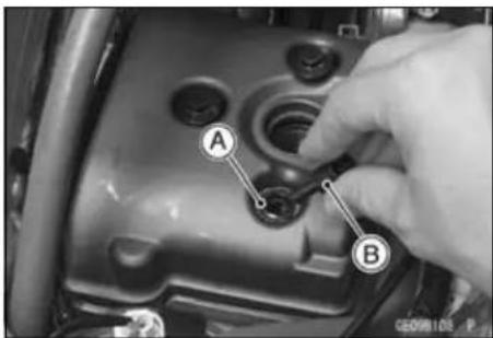
Camshaft Chain Tensioner
Camshaft Chain Tensioner Removal
NOTICE
This is a non-return type camshaft chain tensioner. The push rod does not return to its original position once it moves out to take up camshaft chain slack. Observe all the rules listed below:
When removing the tensioner, do not take out the mounting bolts only halfway. Retightening the mounting bolts from this position could damage the tensioner and the camshaft chain. Once the bolts are loosened, the tensioner must be removed and reset as described in "Camshaft Chain Tensioner Installation".
Do not turn over the crankshaft while the tensioner is removed. This could upset the camshaft chain timing and damage the valves.
- Remove the starter motor (see Starter Motor Removal in the Electrical System chapter).
- Loosen the cap bolt [A]
- Remove the tensioner mounting bolts [B], and remove the chain tensioner body [C].
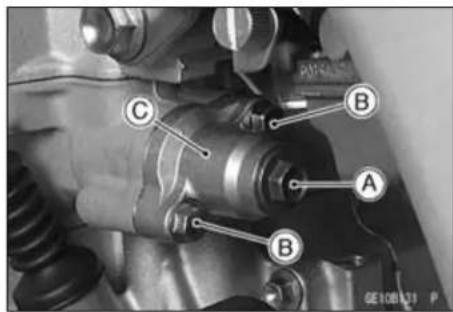
Camshaft Chain Tensioner Installation
- Remove the tensioner cap bolt and O-ring.
- While compressing the push rod [A], turn it clockwise with a suitable screwdriver until the rod stopped.
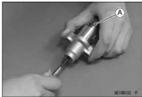
NOTICE
Do not turn the rod counterclockwise at installation. This could detach the rod and the tensioner cannot be reinstalled.
- While holding the rod in position with a suitable push rod holder plate [A] install the tensioner on the cylinder block.
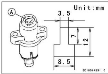
5-16 ENGINE TOP END
Camshaft Chain Tensioner
- Replace the chain tensioner gasket with a new one.
- Tighten:
Torque - Chain Tensioner Mounting Bolts [A]: 9.8 N·m (1.0 kgf·m, 87 in·lb)
• Take out the holder plate [B].
• Install the O-ring and tighten the cap bolt.
Torque - Chain Tensioner Cap Bolt: 5.0 N·m (0.51 kgf·m, 44 in·lb)
- Install the starter motor (see Starter Motor Installation in the Electrical System chapter).
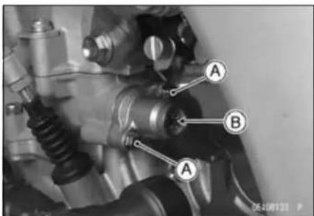
Camshaft
Camshaft Removal
- Remove:
Cylinder Head Cover (see Cylinder Head Cover Removal)
Timing Inspection Cap [A]
Crankshaft Shaft Cap [B]
Special Tool - Filler Cap Driver: 57001-1454
- First, bring the piston to the TDC of the compression stroke.
- Place a wrench over the flywheel nut and turn it counterclockwise to align the TDC mark [A] with the center of the groove [B] of the inspection hole.
- Remove:
Camshaft Chain Tensioner (see Camshaft Chain Tensioner Removal).
Camshaft Cap Bolts [1 \~ 8] (sequence numbers)
Camshaft Caps [A] (together with the oil pipes [B])
- Plug the oil passage and camshaft chain tunnel with a clean cloth for prevent the oil pipe from dropping into the crankcase.
○While keeping parallel, remove the camshaft caps and oil pipes.
- Remove:
Positioning Rings [A]
- Disengage the Camshafts [B] from camshaft chain [C].
- Staff a clean cloth into the camshaft chain tunnel to keep any parts from dropping into the crankcase.
NOTICE
The crankshaft may be turned while the camshafts are removed.
Always pull the chain taut while turning the crankshaft. This avoids kinking the chain on the lower (crankshaft) sprocket. A kinked chain could damage both the chain and the sprocket.
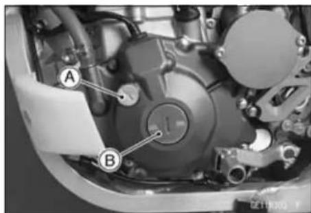
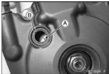
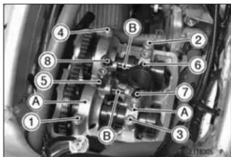
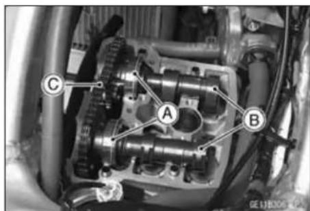
5-18 ENGINE TOP END
Camshaft
- Remove: Bolts [A] Auto-Decompressor [B] (with the sprocket)
- Remove: Circlips [A]
Camshaft Installation
- Assemble the auto-decompressor weights [A] and spring [B] to install it to the sprocket [C].
- Replace the circlips [D] with new ones, and install them.
- Apply a non-permanent locking agent to camshaft sprocket bolts.
- Fit the recess [E] of the weight and projections [F] of the camshaft, and install it.
Torque - Camshaft Sprocket Bolts [G]: 12 N·m (1.2 kgf·m, 106 in·lb)
- Apply molybdenum disulfide oil to the ball bearing, all cam and journal surfaces of the camshaft.
- If the camshaft is replaced with a new part, apply a thin coat of molybdenum disulfide grease to the cam and journal surfaces.
- First, bring the crankshaft to the TDC (of either the compression or exhaust stroke).
○Place a wrench over the flywheel nut and turn it counterclockwise to align the TDC mark [A] with the center of the groove [B] of the inspection hole.
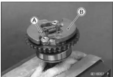
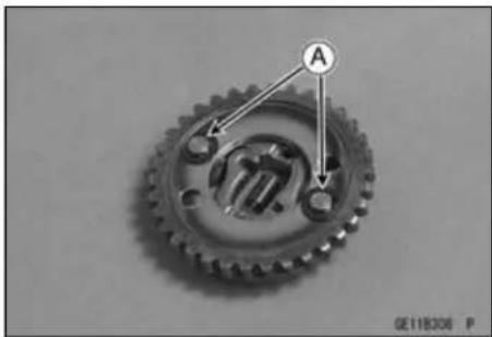
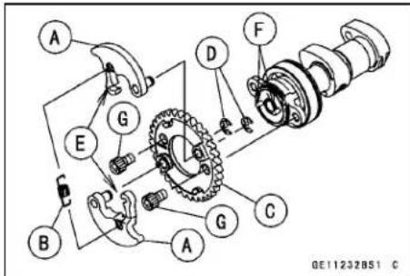

Camshaft
- Engage the camshaft chain with the camshaft sprockets.
○Pull the tension side (exhaust side) of the chain taut to install the chain. - The timing marks on the sprocket must be aligned with the cylinder head upper surface.
- Pull the chain taut and fit it onto the camshaft sprocket.
- Starting with the timing mark on the front of the exhaust sprocket, count to the 1st pin. Feed the exhaust camshaft thought the chain and align the 29th pin with the timing mark on the intake camshaft sprocket.
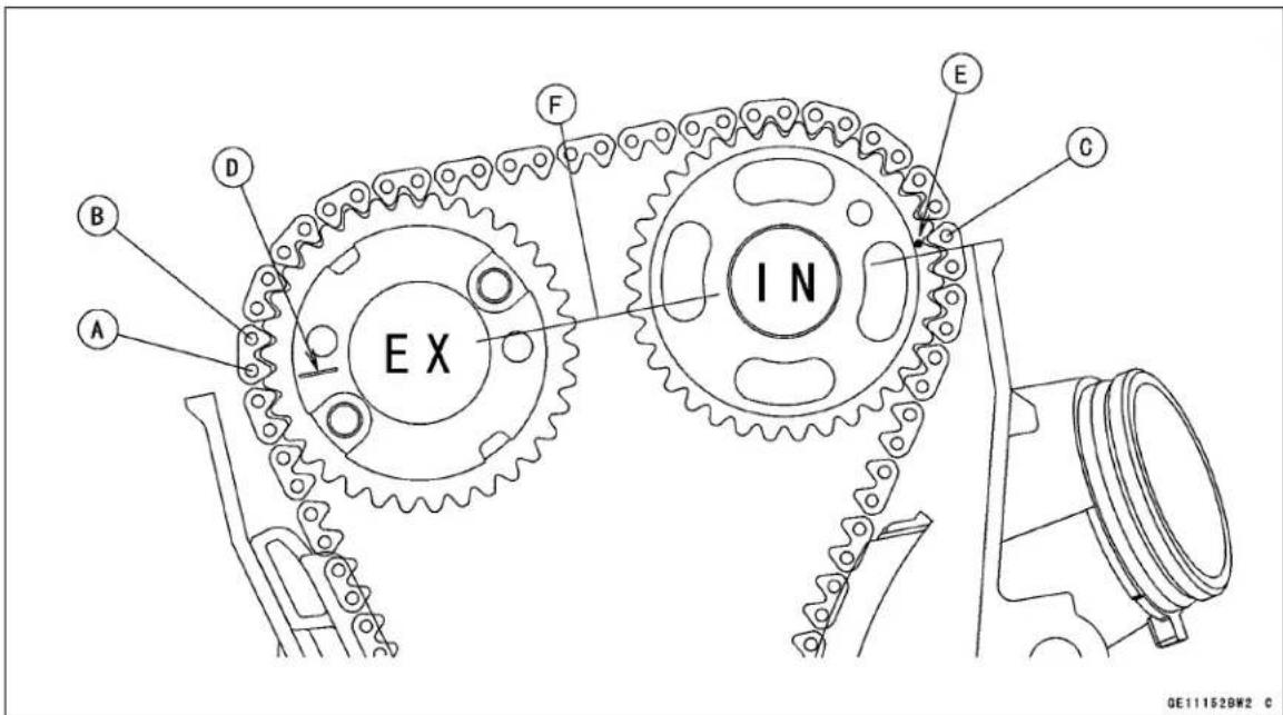
1st Pin [A]
2nd Pin [B]
29th Pin [C]
Mark (exhaust) [D]
Punch Mark (intake) [E]
Upper Cylinder Head Surface [F]
- Be sure to install the positioning rings [A] and dowel pins [B].
- Plug the oil passage and camshaft chain tunnel with a clean cloth for prevent the any parts from dropping in the crankcase.
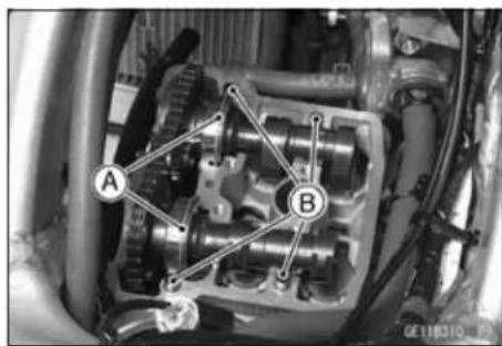
Camshaft
- Apply grease to the rubber portions of the oil pipes.
- Assemble:
Camshaft Caps [A]
Oil Pipes [B] - While keeping parallel, install them.
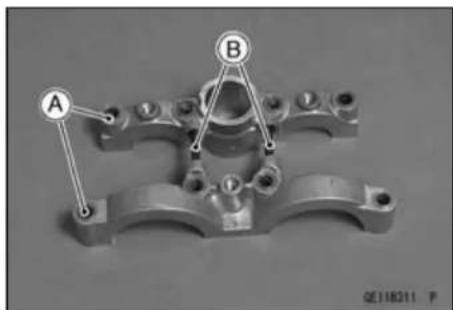
- Uniformly tighten all bolts and after the camshaft has settled, uniformly tighten all the bolts.
○Following the sequence numbers on the camshaft caps. Tighten the cap bolts [1 \~ 8] after applying molybdenum disulfide oil to the thread of them.
Torque - Camshaft Cap Bolts: 9.8 N·m (1.0 kgf·m, 87 in·lb)
- Install the camshaft chain tensioner (see Camshaft Chain Tensioner Installation), then, check the camshaft chain timing.
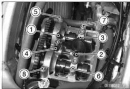
NOTICE
After this procedure, if any resistance is felt while turning over the crankshaft, stop immediately, and check the camshaft chain timing. V alves will be bent if the timing is not properly set.
- Install the cylinder head cover (see Cylinder Head Cover Installation), timing inspection cap, and the balancer shaft cap.
Special Tool - Filler Cap Driver: 57001-1454
Camshaft Chain Removal
- Remove:
Camshaft (see Camshaft Removal)
Flywheel (see Flywheel Removal in the Electrical System chapter)
Oil Pump (Scavenge) Cover Bolts [A]
Lower Chain Guide [B]
Front Chain Guide [C] - Remove the camshaft chain [D] from the crankshaft sprocket.
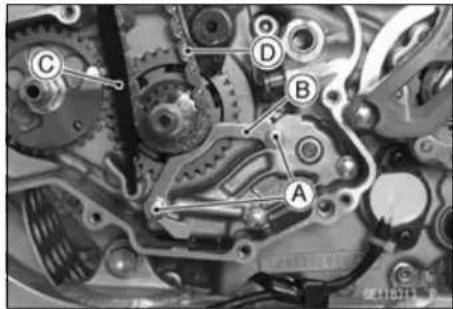
Camshaft Chain Installation
- Hang the camshaft chain [A] to the crankshaft sprocket.
- Install:
Front Chain Guide [B]
Lower Chain Guide [C]
- Tighten:
Torque - Oil Pump (Scavenge) Cover Bolts [D]: 9.8 N·m (1.0 kgf·m, 87 in·lb)
- Install:
Flywheel (see Flywheel Installation in the Electrical System chapter)
Camshaft (see Camshaft Installation)
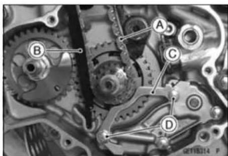
Camshaft
Camshaft and Camshaft Cap Wear
- Measure each clearance between the camshaft journal and camshaft cap using plastigauge (press gauge) [A].
- Install the camshaft caps (see Camshaft Installation).
NOTE
○ Do not turn the camshaft when the plastigauge is between the journal and camshaft cap.
★If any clearance exceeds the service limit, measure the diameter of each camshaft journal with a micrometer.
Camshaft Journal, Camshaft Cap Clearance
Standard: 0.020 \~ 0.061 mm (0.00079 \~ 0.0024 in.)
Service Limit: 0.15 mm (0.0059 in.)
★If the camshaft journal diameter is less than the service limit, replace the camshaft with a new one and measure the clearance again.
Camshaft Journal Diameter
Standard: 22.959 \~ 22.980 mm (0.90390 \~ 0.90472 in.)
Service Limit: 22.93 mm (0.9028 in.)
★If the clearance still remains out of the service limit, replace the cylinder head unit.
Camshaft Runout
- Remove the camshaft (see Camshaft Removal).
- Set the camshaft in a camshaft alignment jig or on V blocks.
- Measure the runout with a dial gauge at the specified place as shown.
★If the runout exceeds the service limit, replace the camshaft.
Camshaft Runout
Standard: TIR 0.02 mm (0.0008 in.) or less
Service Limit: TIR 0.1 mm (0.004 in.)
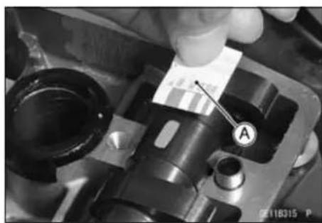
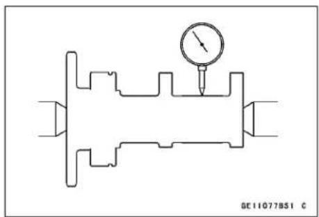
Cam Wear
- Remove the camshaft (see Camshaft Removal).
- Measure the height [A] of each cam with a micrometer.
★If the cams are worn down past the service limit, replace the camshaft.
Cam Height
Standard:
Exhaust 36.443 \~ 36.557 mm (1.4348 \~ 1.4392 in.)
Intake 37.143 \~ 37.257 mm (1.4623 \~ 1.4668 in.)
Service Limit:
Exhaust 36.34 mm (1.431 in.)
Intake 37.04 mm (1.458 in.)
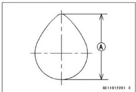
Cylinder Head
Cylinder Compression Measurement
- Start the engine.
- Thoroughly warm up the engine so that the engine oil between the piston and cylinder wall will help seal compression as it does during normal running.
- Stop the engine.
- Remove: Fuel Tank (see Fuel Tank Removal in the Fuel System chapter)
- Remove the spark plug [A] with spark plug wrench [B] (or owner's tool).
Special Tool - Spark Plug Wrench, Hex 16: 57001-1262
Owner's Tool -Spark Plug Wrench: 92110-0005
- Attach the compression gauge [A] and the adapter hose [B] firmly into the spark plug hole.
- With the throttle fully open, turn the engine with the kick-starter or the starter motor until the compression gauge stops rising; the compression is the highest reading obtainable.
Special Tools - Compression Gauge: 57001-221 Compression Gauge Adapter, M10 × 1.0: 57001-1317
Cylinder Compression
Usable Range: 450 \~ 750 kPa (4.59 \~ 7.65 kgf/cm², 65.2 \~ 109 psi) @ 5 kicks (kickstarter)
Usable Range: 450 \~ 750 kPa (4.59 \~ 7.65 kgf/cm², 65.2 \~ 109 psi) @ 420 r/min (rpm)(Electric Starter)
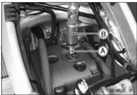
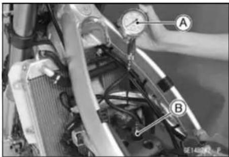
• Install the spark plug.
Torque - Spark Plug: 13 N·m (1.3 kgf·m, 115 in·lb)
- Pull the spark plug cap lightly to make sure the installation of the spark plug cap.
Cylinder Head
| Problem Diagnosis | Diagnosis Remedy (Action) | |
| The cylinder compression is higher than the usable range | Carbon accumulation on piston and in cylinder head (combustion chamber) is suspected due to damaged valve stem or piston oil rings. | Remove the carbon deposits and replace damaged parts if necessary. |
| Incorrect cylinder head gasket thickness. | Replace the gasket with a standard one. | |
| Damaged auto-decompressor spring or decompressor do not move smoothly. | Replace the spring or auto-decompressor. | |
| The cylinder compression is lower than the usable range | Exhaust gas leakage around cylinder head. | Replace the damaged gasket and check cylinder head warp. |
| Incorrect seating surface of valve. | Repair seating surface if possible. | |
| Valve clearance is too narrow. | Adjust the valve clearance. | |
| Piston/cylinder clearance is too wide. | Replace the piston and/or cylinder | |
| Piston seizure. | Inspect the cylinder and piston; repair or replace them if necessary. | |
| Bad condition of piston ring and/or piston ring grooves. | Replace the piston and/or the piston rings. | |
| Auto-decompressor do not move smoothly. | Replace the auto-decompressor. |
Cylinder Head Removal
- Remove:
Fuel Tank (see Fuel Tank Removal in the Fuel System chapter)
Starter Motor (see Starter Motor Removal in the Electrical System chapter)
Camshaft Chain Tensioner (see Camshaft Chain Tensioner Removal)
Cylinder Head Cover (see Cylinder Head Cover Removal)
Camshaft (see Camshaft Removal)
Exhaust Pipe (see Muffler Removal)
Carburetor (see Carburetor Removal in the Fuel System chapter)
Vacuum Switch Valve [A] (see Vacuum Switch Valve Removal)(equipped models)
Clamp Screw [B]
Water Hose [C]
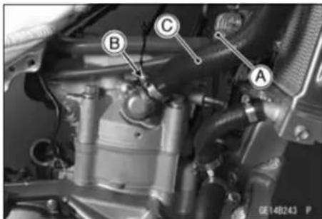
- Remove:
Engine Bracket Bolts [A]
Engine Bracket [B]
- Remove the 6 mm cylinder head bolts [C] and loosen the cylinder bolt [D].
○This prevents the 6 mm bolts from becoming damaged.
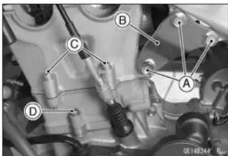
5-24 ENGINE TOP END
Cylinder Head
- Remove the vacuum switch valve hose [A] and vacuum hose [B] from the cylinder head (equipped models).
- Remove the 10 mm cylinder head bolts following the tightening sequence [1 \~ 4] as shown.
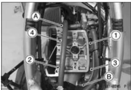
- Tap lightly up with a plastic mallet [A] to separate the cylinder head [B] from the cylinder.
- Remove the cylinder head gasket.
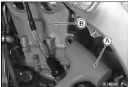
Cylinder Head Installation
- Fit the projection [A] of the front camshaft chain guide [B] in the groove [C] of the cylinder.
○Insert the guide end [D] into the recess [E] of the crankcase securely.
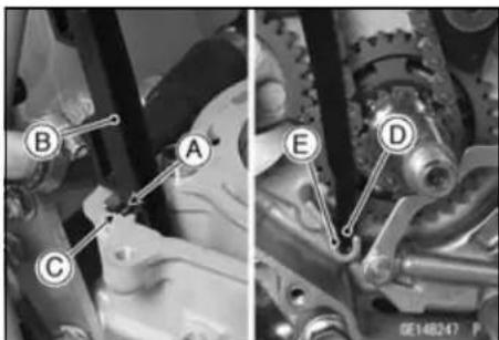
- Install:
Dowel Pins [A]
New Cylinder Head Gasket [B]
• Install the cylinder head.
The camshaft caps are machined with the cylinder head; therefore, if a new cylinder head is installed, use the caps that are supplied with the new head.
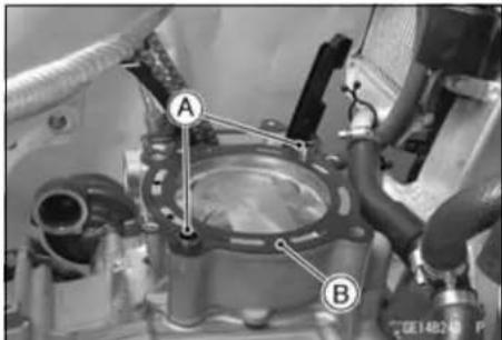
- Apply molybdenum disulfide oil to the both sides [A] of the 10 mm cylinder head bolt washer and thread [B] of the 10 mm cylinder head bolts.
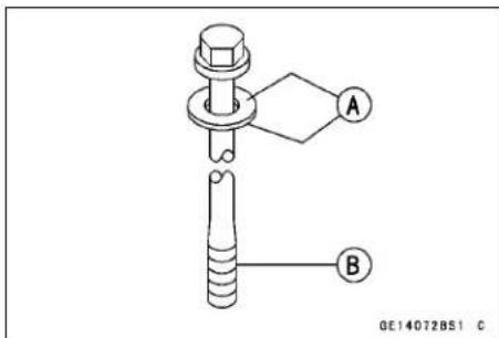
Cylinder Head
- Tighten the 10 mm cylinder head bolts in the numbered sequence [1 \~ 4].
Torque - Cylinder Head Bolts (M10): 59 N·m (6.0 kgf·m, 44 ft·lb)
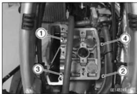
- Tighten:
Torque - Cylinder Bolt [A]: 12 N·m (1.2 kgf·m, 106 in·lb) Cylinder Head Bolts (M6) [B]: 12 N·m (1.2 kgf·m, 106 in·lb)
- Install:
Camshaft (see Camshaft Installation)
Cylinder Head Cover (see Cylinder Head Cover Installation)
Engine Bracket [C] (see Engine Installation in the Engine Removal/Installation chapter)
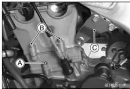
- Connect the Water hose, and tighten the hose clamp screw.
- Install:
Vacuum Switch Valve (see Vacuum Switch Valve Installation)(equipped models)
Carburetor (see Carburetor Installation in the Fuel System chapter)
Starter Motor (see Starter Motor Installation in the Electrical System chapter)
Exhaust Pipe (see Muffler Installation)
Fuel Tank (see Fuel Tank Installation in the Fuel System chapter)
Cylinder Head Cleaning
- Refer to the Cylinder Head Warp Inspection in the Periodic Maintenance chapter.
Cylinder Head Warp
- Refer to the Cylinder Head Warp Inspection in the Periodic Maintenance chapter.
Valves
Valve Clearance Inspection
- Refer to the Valve Clearance Inspection in the Periodic Maintenance chapter.
Valve Removal
- Remove the cylinder head (see Cylinder Head Removal). - Remove the valve lifter and the shim from the valve.
NOTE
○Use the valve spring compressor assembly and the adapter to press down the valve spring retainer.
Special Tools - Valve Spring Compressor Assembly: 57001-241 [A]
Valve Spring Compressor Adapter, φ24: 57001-1586 [B]
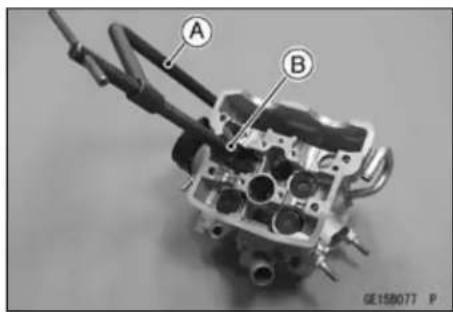
Valve Installation
NOTICE
Do not lap the valve to the valve seat, using the grinding compound. It will come off oxide film treated surface of the valve.
- Visually inspect the valve surface.
★If the surface is damaged, replace it. - Replace the oil seal [C] with a new one.
- Apply a thin coat of molybdenum disulfide grease to the valve stem [A] before installing the valve.
- Check to make sure that the valve moves up and down smoothly.
- Check to make sure that the valve and the valve seat are making proper contact.
- Install the inner valve spring [D] and outer valve spring [E] so that the closed coil end faces the spring seat [B].
- Compress the valve springs to install the split keepers [G] in order to secure the spring retainer [F] in place.
Special Tools - Valve Spring Compressor Assembly: 57001 -241
Valve Spring Compressor Adapter, φ24: 57001-1586
- The shim [H] must be installed with its thickness indication facing up towards the retainer.
○Apply high temperature grease to the shim or to the retainer to prevent the shim from falling off when the camshaft is being installed. - Apply engine oil to the valve lifter [l] surface, then install the lifter.
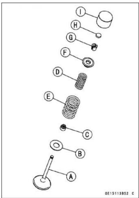
Valves
Valve Guide Removal
- Remove:
Valve (see Valve Removal)
Oil Seal
Spring Seat
- Heat the area around the valve guide up to 120 \~ 150°C (248 \~ 302°F).
NOTICE
Do not heat the cylinder head with a torch. This will warp the cylinder head. Soak the cylinder head and heat the oil.
- Hammer lightly on the valve guide arbor [A] to remove the guide.
Special Tool - Valve Guide Arbor, 5/5: 57001-1021
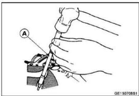
Valve Guide Installation
- Apply a thin coat of oil to the outer surface of the valve guide.
- Heat the area around the valve guide up to 120 \~ 150°C (248 \~ 302°F).
NOTICE
Do not heat the cylinder head with a torch. This will warp the cylinder head. Soak the cylinder head and heat the oil.
- Assemble the valve guide driver [A] and valve guide driver attachment D [B].
Special Tools - Valve Guide Driver, 4.5: 57001-1564 Valve Guide Driver Attachment D: 57001-1659
- When install the exhaust valve guide, using the attached washer (t = 2.0) [C].
- Using the valve guide driver, press and insert the valve guide in until the valve guide driver surface [D] touches the head surface.
[E] Exhaust 11.1 \~ 11.3 mm (0.437 \~ 0.445 in.)
[F] Intake 13.1 \~ 13.3 mm (0.516 \~ 0.524 in.)
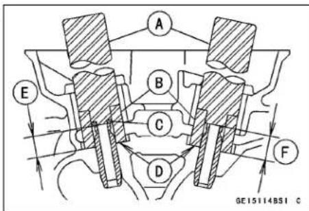
Valves
- Ream the valve guide with valve guide reamer [A], even if the old guide is reused.
Special Tool - Valve Guide Reamer, φ5.5: 57001-1079
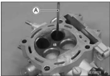
Valve/Valve Guide Clearance Measurement (Wobble Method)
○If a small bore gauge is not available, inspect the valve guide wear by measuring the valve/valve guide clearance with the wobble method as indicated below.
- Insert a new valve [A] into the guide [B] and set a dial gauge against the stem perpendicular to it as close as possible to the cylinder head mating surface.
- Move the stem back and forth [C] to measure the valve wobble.
- Repeat the measurement in a direction at a 90° angle to the first measurement.
★If the reading exceeds the service limit, replace the guide.
NOTE
○ The reading is greater than the actual valve/valve guide clearance because the measurement is taken outside of the guide.
Valve/Valve Guide Clearance Measurement (Wobble Method)
Standard:
Exhaust 0.09 \~ 0.16 mm (0.0035 \~ 0.0063 in.)
Intake 0.06 \~ 0.14 mm (0.0024 \~ 0.0055 in.)
Service Limit:
Exhaust 0.36 mm (0.014 in.)
Intake 0.33 mm (0.013 in.)
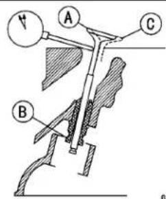
GE15010451 C
Valves
Valve Seat Inspection
- Remove the valve (see Valve Removal).
- Check the valve seating surface [A] between the valve [B] and valve seat [C].
- Measure the outside diameter [D] of the seating pattern on the valve seat.
★If the outside diameter is too large or too small, repair the seat. (see Valve Seat Repair)
Valve Seating Surface Outside Diameter
Standard:
Exhaust 29.4 \~ 29.6 mm (1.16 \~ 1.17 in.)
Intake 34.4 \~ 34.6 mm (1.35 \~ 1.36 in.)
- Check the seating surface width of the valve seat.
○Measure the seat width [E] of the portion where there is no build-up carbon (white portion) of the valve seat with a vernier caliper.
Good [F]
Valve Seating Surface Width
Standard:
Exhaust 0.8 \~ 1.2 mm (0.03 \~ 0.047 in.)
Intake 0.5 \~ 1.0 mm (0.02 \~ 0.039 in.)
★If the width is too wide [G], too narrow [H] or uneven [J], repair the seat (see Valve Seat Repair).
Valve Seat Repair
- For the instructions on how to use the valve seat cutter [A], follow the operation manual provided by the to manufacturer.
Special Tools - Valve Seat Cutter Holder, φ 5.5 : 57001-1125 [B]
Valve Seat Cutter Holder Bar: 57001-1128
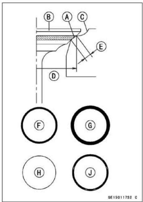
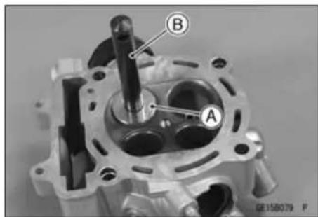
Exhaust: Valve Seat Cutter, 45° - φ35: 57001- 1116
Valve Seat Cutter, 32°-φ35: 57001-1121
Valve Seat Cutter, 55° -φ35: 57001-1247
Intake: Valve Seat Cutter, 45°-φ40: 57001-1496
Valve Seat Cutter, 32° - φ38.5: 57001-1122
Valve Seat Cutter, 55° - φ38.5: 57001-1497
★If the tool manufacturer's instructions are not available, operate in accordance with the following procedure.
Valves
Seat Cutter Operation Care
- This valve seat cutter is developed to grind the vale for repair. Therefore the cutter must not be used for other purposes than seat repair.
- Do not drop or shock the valve seat cutter, or the diamond particles may fall off.
- Do not fail to apply engine oil to the valve seat cutter before grinding the seat surface. Also wash off ground particles sticking to the cutter with washing oil.
NOTE
○Do not use a wire brush to remove the metal particles from the cutter. It will take off the diamond particles.
- Setting the valve seat cutter holder in position, operate the cutter in one hand. Do not apply too much force to the diamond portion.
NOTE
○Prior to grinding, apply engine oil to the cutter and during the operation, wash off any ground particles sticking to the cutter with washing oil.
- After use, wash it with washing oil and apply thin layer of engine oil before storing.
Marks Stamped on the Cutter
The marks stamped on the back of the cutter [A] represent the following.
60° ....Cutter Angle [B]
37.5φ …… Cutter Outer Diameter [C]
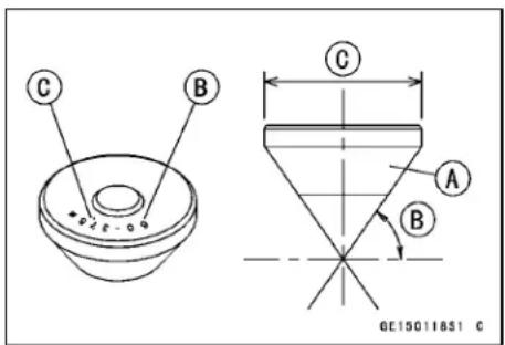
Repair Operating Procedures
- Clean the seat area carefully.
- Coat the seat with machinist's dye.
- Fit a 45° cutter into the holder and slide it into the valve guide.
- Press down lightly on the handle and turn it right or left. Grind the seating surface only until it is smooth.
NOTICE
Do not grind the seat too much. Overgrinding will reduce valve clearance by sinking the valve into the head. If the valve sinks too far into the head, it will be impossible to adjust the clearance, and the cylinder head must be replaced.
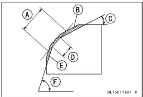
Widened Width [A] of engagement by machining with 45° cutter Ground Volume [B] by 32° cutter 32° [C] Correct Width [D] Ground Volume [E] by 55° cutter 55° [F]
Valves
- Measure the outside diameter of the seating surface with a vernier caliper.
★If the outside diameter of the seating surface is too small, repeat the 45° grind until the diameter is within the specified range.
Original Seating Surface [B]
○Remove all pittings of flaws from 45° ground surface.
○Alter grinding with 45° cutter, apply thin coat of machinist's dye to 45° [A] seating surface. This makes seating surface distinct and 32° and 55° grinding operation easier.
When the valve guide is replaced, be sure to grind with 45° cutter for centering and good contact.
★If the outside diameter [A] of the seating surface is too large, make the 32° grind described below.
★If the outside diameter of the seating surface is within the specified range, measure the seat width as described below.
- Grind the seat at a 32° angle [B] until the seat O.D. is within the specified range.
To make the 32° grind, fit a 32° cutter into the holder, and slide it into the valve guide.
○Turn the holder one turn at a time while pressing down very lightly. Check the seat after each turn.
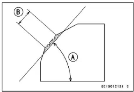
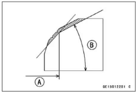
NOTICE
The 32° cutter removes material very quickly. Check the seat outside diameter frequently to prevent overgrinding.
○After making the 32° grind, return to the seat O.D. measurement step above.
- To measure the seat width, use a vernier caliper to measure the width of the 45° angle portion of the seat at several places around the seat.
★If the seat width is too narrow, repeat the 45° grind until the seat is slightly too wide, and then return to the seat O.D. measurement step above.
★If the seat width is too wide, make the 55° [A] grind described below.
★If the seat width is within the specified range, lap the valve to the seat as described below.
- Grind the seat at a 55° angle until the seat width is within the specified range.
To make the 55° grind, fit a 55° cutter into the holder, and slide it into the valve guide.
○Turn the holder, while pressing down lightly.
○After making the 55° grind, return to the seat width measurement step above.
Correct Width [B]
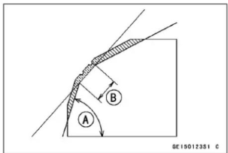
Valves
- The seating area should be marked about in the middle of the valve face.
★If the seat area is not in the right place on the valve, check to be sure the valve is the correct part. If it is, it may have been refaced too much; replace it. - When the engine is assembled, be sure to adjust the valve clearance (see Valve Clearance Adjustment in the Periodic Maintenance chapter).
Valves
Valve Seat Repair
![graph TD A["START"] --> B["Machinist's dye on seat"] B --> C["45° Grind"] C --> D["Measure Seating Area O.D."] D --> E{Tools: Venire Caliper\nPurpose: check seat O.D.\nagainst spec.} E --> F["Results"] F --> G["Too small"] F --> H["OK"] F --> I["Too big"] G --> J["45° Grind"] H --> K["Measure Seatin…](/content/2026/05/818283/images/70eee9eb1824d0a91cbd441889b1f42a62a3e6d53182079d7ede0039bcc3dec6.jpg)
5-34 ENGINE TOP END
Cylinder and Piston
Cylinder Removal
- Remove:
Cylinder Head (see Cylinder Head Removal) Front Camshaft Chain Guide [A] Cylinder Bolt [B] - Tap lightly up with a plastic mallet to separate the cylinder from the crankcase.
- Remove the cylinder base gasket.
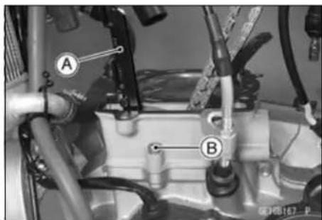
Piston Removal
- Remove the cylinder (see Cylinder Removal).
- Place a clean cloth under the piston and remove the piston pin snap ring [A] from one end of the piston pin.
NOTICE
Do not reuse snap rings, as removal weakens and deforms them. They could fall out and score the cylinder wall.
- Remove the piston pin, using a piston pin puller.
Special Tool - Piston Pin Puller Assembly: 57001-1568 [A] - Remove the piston.
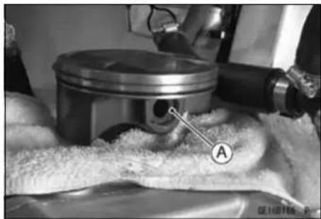
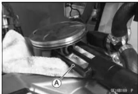
- Carefully spread the ring opening with your thumbs and then push up on the opposite side of the ring [A] to remove it.
- Remove the oil ring in the same procedure.
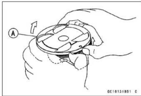
Cylinder and Piston Installation
NOTE
○ The oil ring rails have no "top" or "bottom".
- Install the oil ring expander [A] in the bottom piston ring groove so the ends [B] butt together.
- Install the oil ring steel rails, one above the expander and one below it.
○Spread the rail with your thumbs, but only enough to fit the rail over the piston.
○Release the rail into the bottom piston ring groove.
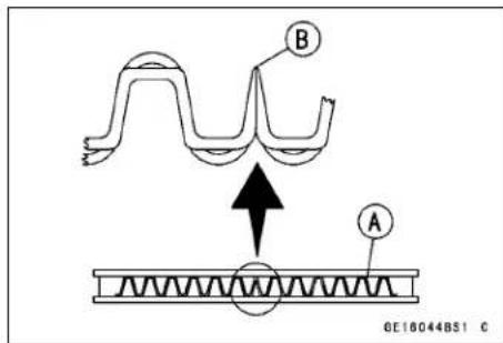
Cylinder and Piston
- Install the top ring [A] so that the "R" mark [B] faces up.
NOTE
○ If a new piston or cylinder is used, check piston to cylinder clearance (see Piston/Cylinder Clearance), and use new piston rings.
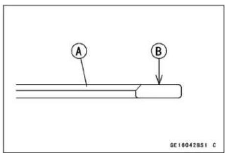
- Apply engine oil to the inside wall of the small end of the connecting rod.
- Face the circle mark [A] on the top of the piston must point toward the front [B] of the engine.
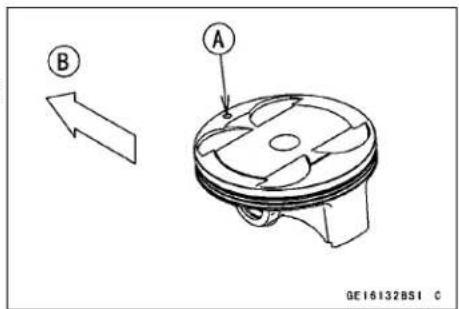
- Fit a new piston pin snap ring into the side of the piston so that the ring opening [A] does not coincide with the slit [B] of the piston pin hole.
When installing the piston pin snap ring, compress it only enough to install it and no more.

NOTICE
Do not reuse snap rings, as removal weakens and deforms them. They could fall out and score the cylinder wall.
- Install:
Dowel Pins [A]
New Cylinder Base Gasket [B]
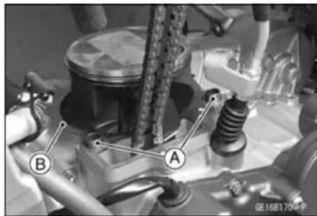
- The piston ring openings must be positioned as shown in the figure. The openings of the oil ring steel rails must be 20° of angle from the opening of the oil ring expander.
Circle Mark [A]
Top Ring [B]
Upper Oil Ring Steel Rails [C]
Oil Ring Expander [D]
Lower Oil Ring Steel Rail [E]
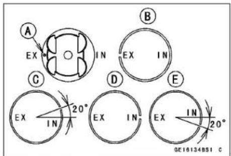
Cylinder and Piston
- Apply engine oil to the cylinder bore.
● Determine the position of the piston ring ends. - Install the cylinder while compressing the piston rings with your fingers or the special tool [A].
Special Tools - Piston Ring Compressor Grip: 57001-1095
Piston Ring Compressor Belt, φ 95 φ 108 57001-1358
- Drive the front chain guide in.
• Install the removed parts.
Cylinder Wear
- Refer to the Cylinder Wear Inspection in the Periodic Maintenance chapter.
Piston Wear
- Using a micrometer, measure the outside diameter [A] of each piston 8.5 mm (0.33 in.) [B] up from the bottom of the piston at a right angle to the direction of the piston pin.
★If the pistons outside diameter is smaller than the service limit, replace the piston.
Piston Diameter
Standard: 95.970 \~ 95.980 mm (3.7783 \~ 3.7787 in.)
Service Limit: 95.82 mm (3.772 in.)
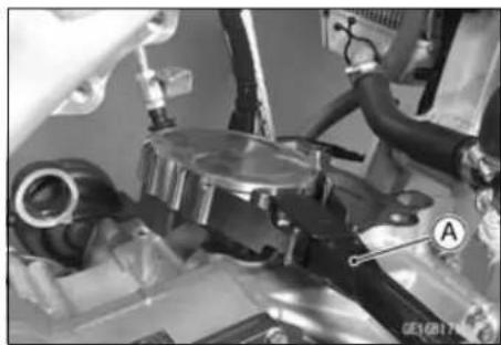
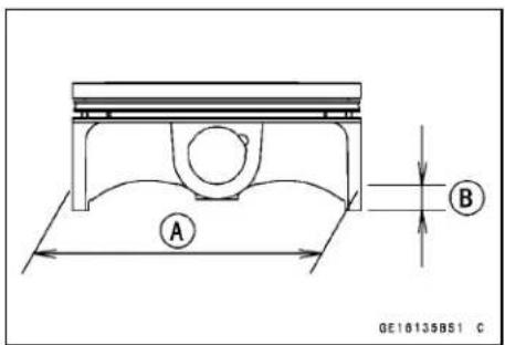
Piston/Cylinder Clearance
- Refer to the Piston/Cylinder Clearance in the Periodic Maintenance chapter.
Piston Ring/Ring Groove Clearance
- Check for uneven groovewear by inspecting the ring seating.
★The rings should fit perfectly parallel to groove surfaces. If not, replace the piston and all the piston rings. - With the piston rings in their grooves, make several measurements with a thickness gauge [A] to determine piston ring/groove clearance.
Piston Ring/Ring Groove Clearance
Standard:
Top
0.04 \~ 0.08 mm (0.002 \~ 0.003 in.)
Service Limit:
Top
0.18 mm (0.0071 in.)
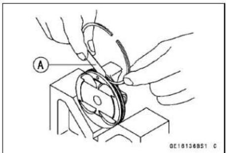
★If the piston ring groove clearance is greater than the service limit, measure the ring thickness and groove width as follows to decide whether to replace the rings, the piston or both.
Cylinder and Piston
Piston Ring Groove Width
- Measure the groove width at several points around the piston with a vernier caliper.
Piston Ring Groove Width
Standard:
Top 1.03 \~ 1.05 mm (0.0406 \~ 0.0413 in.)
Service Limit:
Top 1.13 mm (0.0445 in.)
★If any of the groove widths exceeds the service limit, replace the piston.
Piston Ring Thickness
- Measure the thickness at several points around ring with a micrometer.
Piston Ring Thickness
Standard:
Top 0.970 \~ 0.990 mm (0.0382 \~ 0.0390 in.)
Service Limit:
Top 0.90 mm (0.035 in.)
★If any of the measurements is less than the service limit on either of the rings, replace the rings as a set.
NOTE
○ When using new rings in a used piston, check for uneven groove wear. The rings should fit perfectly parallel to the groove sides. If not, replace the piston.
Piston Ring End Gap Measurement
- Place the piston ring [A] inside the cylinder, using the piston to locate the ring squarely in place. Place the piston ring close to the bottom of the cylinder, where cylinder wear is minimal
- Measure the gap [B] between the ends of the ring using a thickness gauge.
★If the ring end gap exceeds the service limit, replace the ring.
Piston Ring End Gap
Standard:
| Top | 0.25 ~ 0.35 mm (0.0098 ~ 0.014 in.) |
| Oil | 0.15 ~ 0.50 mm (0.0059 ~ 0.020 in.) |
Service Limit:
| Top | 0.6 mm (0.02 in.) |
| Oil | 0.8 mm (0.03 in.) |
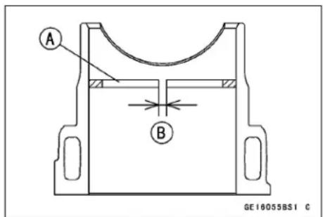
Cylinder and Piston
Piston, Piston Pin, Connecting Rod Wear Inspection
- Visually inspect the snap rings [A] still fitted in place.
★If the rings show weakness or deformation, replace the rings. Also if the pin hole groove shows excessive wear, replace the piston. - Measure the diameter of the piston pin [B] with a micrometer.
★If the piston pin diameter is less than the service limit at any point, replace the piston pin. - Using a cylinder gauge, measure the diameter of both of piston pin holes [C] in the piston and the inside diameter of the connecting rod small end [D].
★If either piston pin hole diameter exceeds the service limit, replace the piston.
★If the connecting rod small end inside diameter exceeds the service limit, replace the connecting rod.
Piston Pin Diameter
Standard: 18.991 \~ 19.000 mm (0.74768 \~ 0.74803 in.)
Service Limit: 18.96 mm (0.7465 in.)
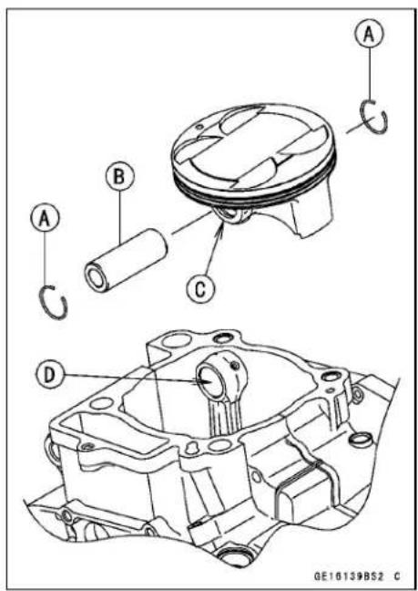
Piston Pin Hole Diameter
Standard: 19.004 \~ 19.010 mm (0.74819 \~ 0.74842 in.)
Service Limit: 19.08 mm (0.7512 in.)
Connecting Rod Small End Inside Diameter
Standard: 19.019 \~ 19.030 mm (0.74878 \~ 0.74921 in.)
Service Limit: 19.07 mm (0.7508 in.)
Carburetor Holder
Carburetor Holder Installation
- Install the carburetor holder [A] with the marked [B] side facing toward the cylinder head outside.
○Install the holder clamp [C] with its screw head [D] facing left side.
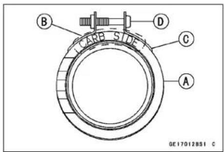
Torque - Carburetor Holder Clamp Screws: 2.0 N·m (0.20 kgf·m, 18 in·lb)
- Fit the recess [A] of the holder into the projection [B] of the cylinder head.
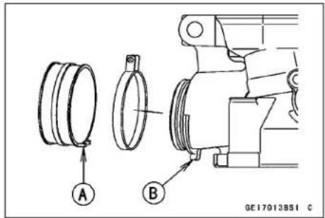
Muffler
WARNING
The muffler can become extremely hot during normal operation and cause severe burns. Do not remove the muffler while it is hot.
Muffler Removal
- Loosen the muffler clamp bolt [A].
- Remove the exhaust pip holder nuts [B].
- Remove the exhaust pipe [C] and muffler clamp.
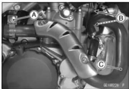
- Remove:
Right Side Cover (see Side Cover Removal in the Frame chapter) - Remove the muffler mounting bolts [A].
- Remove the muffler [B] from the back.
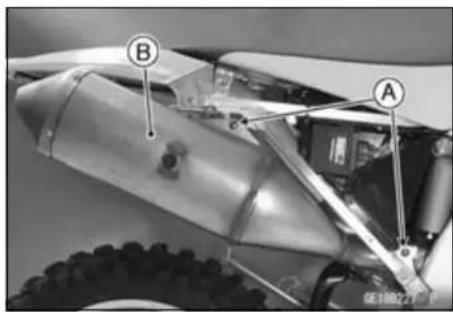
Muffler Installation
- Replace the holder gasket [A] with a new one.
- Check the gasket [B] at the clamp and replace it if it is damaged. Make sure that the gasket is placed securely outside the exhaust pipe.
- First, tighten the exhaust pipe holder nuts and rear muffler mounting bolt temporary.
- Second, pull the muffler backward and tighten the front muffler mounting bolt temporary.
Torque - Front Muffler Mounting Bolt (First) : 9.8 N·m (1.0 kgf·m, 87 in·lb)
- Third, tighten the rear muffler mounting bolt and exhaust pipe holder nuts in order to the specified torque.
Torque - Rear Muffler Mounting Bolt : 20 N·m (2.0 kgf·m, 15 ft·lb)
Exhaust Pipe Holder Nuts : 20 N·m (2.0 kgf·m, 15 ft·lb)
- Fourth, tighten the exhaust pipe clamp bolt securely.
- Lastly, tighten the front muffler mounting bolt to the specified torque.
Torque - Front Muffler Mounting Bolt (Final) : 20 N·m (2.0 kgf·m, 15 ft·lb)
- Thoroughly warm up the engine, wait until the engine cools down, and then retighten the exhaust pipe holder nuts, and the clamp bolt securely.
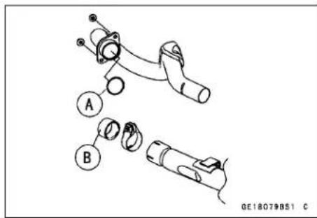
Spark Arrester Cleaning
- Refer to the Spark Arrester Cleaning in the Periodic Maintenance chapter.
Muffler
Exhaust System Inspection
- The exhaust system, in particular the silencer, is designed to reduce exhaust noise and conduct the exhaust gases away from the rider while minimizing power loss. If carbon has built up inside the silencer, exhaust efficiency is reduced, causing engine performance to drop.
★If the silencer is badly damaged, dented, cracked or rusted, replace it. Clean the spark arrester if the exhaust noise becomes too loud or engine performance drops.
Engine Right Side
Table of Contents
Exploded View.... 6-2
Specifications 6-6
Special Tools 6-7
Clutch Lever and Cable 6-8
Clutch Lever Free Play Inspection 6-8
Clutch Lever Free Play Adjustment 6-8
Clutch Lever Installation.... 6-8
Clutch Cable Removal 6-8
Clutch Cable Installation 6-9
Clutch Cable Inspection and Lubrication 6-9
Clutch Cover and Right Engine Cover 6-10
Clutch Cover Removal 6-10
Clutch Cover Installation 6-10
Right Engine Cover Removal.... 6-10
Right Engine Cover Installation.... 6-11
Release Shaft Removal 6-11
Release Shaft Installation 6-12
Clutch 6-13
Clutch Removal 6-13
Clutch Installation.... 6-13
Clutch Plate Assembly Free Play Inspection/Adjustment 6-16
Friction and Steel Plates Wear, Damage Inspection.... 6-16
Friction and Steel Plate Warp Inspection 6-16
Clutch Spring Free Length Inspection.... 6-16
Clutch Housing Finger Damage 6-17
Friction Plate/Clutch Housing Clearance 6-17
Clutch Hub Spline Damage.... 6-17
Primary Gear 6-18
Primary Gear Removal 6-18
Primary Gear Installation 6-18
External Shift Mechanism.... 6-19
External Shift Mechanism Removal 6-19
External Shift Mechanism Installation 6-19
External Shift Mechanism Inspection.... 6-20
Kickstarter.... 6-22
Kick Pedal Assy Removal 6-22
Kick Pedal Assy Installation 6-22
Kick Pedal Assy Disassembly.... 6-22
Kick Pedal Assy Assembly.... 6-22
Idle Gear Removal 6-22
Idle Gear Installation 6-23
Kickshaft Removal 6-23
Kickshaft Installation 6-23
Kick Shaft Assembly Disassembly/Assembly 6-24
Exploded View
| No. | Fastener | Torque | Remarks | ||
| N·m | kgf·m ft·lb | ||||
| 1 | Primary Gear Nut 98 10 72 Lh,R | ||||
| 2 | Clutch Cover Bolts 9.8 1.0 87 in·lb | ||||
| 3 | Right Engine Cover Bolts 9.8 1.0 87 in·lb | ||||
| 4 | Clutch Spring Bolts | 8.8 | 0.90 | 78 in·lb | |
| 5 | Clutch Hub Nut | 98 10 72 | R | ||
- Primary Gear
- Push Rod Holder
- Release Lever Shaft
- Clutch Lever
- Clutch Cable
- Clutch Hub
- Clutch Housing
- Clutch Spring Plate
- Friction Plates (Width of the lining blocks are wide.)
- Friction Plates (Width of the lining blocks are narrow.)
- Steel Plates
CL: Apply cable lubricant.
EO: Apply engine oil.
G: Apply grease.
HG: Apply high-temperature grease.
Lh: Left-hand Threads
M: Apply molybdenum disulfide grease.
MO: Apply molybdenum disulfide oil.
R: Replacement Parts
Exploded View
| No. | Fastener | Torque | Remarks | ||
| N·m | kgf·m ft·lb | ||||
| 1 | Ratchet Guide Bolt | 8.8 | 0.90 | 78 in·lb | |
| 2 | Kick Pedal Bolt 25 2.5 18 L | ||||
| 3 | Ratchet Plate Mounting Bolt | 9.8 | 1.0 | 87 in·lb | S |
| 4 | Ratchet Plate Mounting Screw | 6.4 | 0.65 | 56 in·lb | L,S |
| 5 | Gear Set Lever Nut | 8.8 | 0.90 | 78 in·lb | |
| 6 | Shift Drum Cam Bolt | 24 | 2.4 | 18 | L |
-
Kick Pedal
-
Kickshaft Idle Gear
-
Ratchet Gear
-
Kick Gear
-
Shift Pedal
-
Ratchet Plate
-
Ratchet Assembly
-
Gear Set Lever
-
Shift Drum Cam
-
Shift Shaft
G: Apply grease.
L: Apply a non-permanent locking agent.
MO: Apply molybdenum disulfide oil.
R: Replacement Parts
St: Stake the fasteners.
Specifications
| Item Standard Service | Limit | |
| Clutch LeverClutch Lever Free Play (Lever pointed end) | 8 ~ 13 mm (0.3 ~ 0.5 in.) | - - - |
| ClutchFriction Plate ThicknessFriction Plate WarpSteel Plate WarpClutch Spring Free LengthFriction Plate/Clutch Housing ClearanceClutch Plate Assembly Length | 2.92 ~ 3.08 mm (0.115 ~ 0.121 in.)0.15 mm (0.0059 in.) or less0.2 mm (0.008 in.) or less49.2 mm (1.94 in.)0.20 ~ 0.60 mm (0.0079 ~ 0.024 in.)34.9 ~ 35.5 mm (1.37 ~ 1.40 in.) | 2.6 mm (0.10 in.)0.3 mm (0.01 in.)0.3 mm (0.01 in.)46.7 mm (1.84 in.)0.8 mm (0.03 in.)- - - |
Special Tools
Outside Circlip Pliers:
57001-144
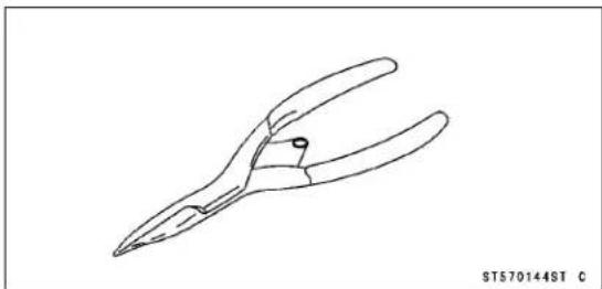
Gear Holder, m2.0:
57001-1557
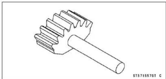
Clutch Holder:
57001-1243
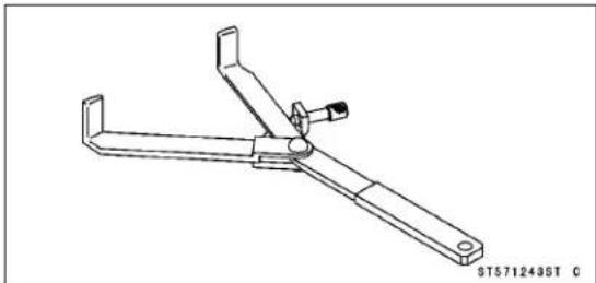

6-8 ENGINE RIGHT SIDE
Clutch Lever and Cable
Due to friction plate wear and clutch cable stretch over a long period of use, the clutch must be adjusted in accordance with the Periodic Maintenance Chart.
WARNING
The engine and exhaust system get extremely hot during normal operation and can cause serious burns. Never touch the engine or exhaust chamber during clutch adjustment.
Clutch Lever Free Play Inspection
- Refer to the Clutch Lever Free Play Check in the Periodic Maintenance chapter.
Clutch Lever Free Play Adjustment
- Refer to the Clutch Lever Free Play Adjustment in the Periodic Maintenance chapter.
Clutch Lever Installation
- Install the clutch lever [A] so that it incline 20° ± 5° [B] more than the horizontal line [C], and position it from the edge of the gripto 170 mm (6.69 in.) [D].
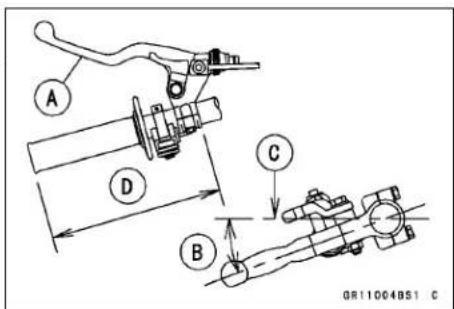
Clutch Cable Removal
- Loosen the adjusting nuts [A] fully at the lower end of the clutch cable.
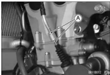
- Slide the adjuster cover [A] and clutch lever dust cover [B] back.
- Screw the adjuster [C] at the clutch lever fully.
- Line up the slots [D] in the clutch lever and adjuster and then free the cable from the lever.
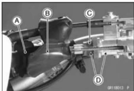
Clutch Lever and Cable
- Free the clutch inner cable tip [A] from the pull rod [B].
NOTICE
Do not remove the clutch release shaft unless it is absolutely necessary. If removed, release shaft oil seal must be replaced with a new one.
- Pull the clutch cable out of the frame.
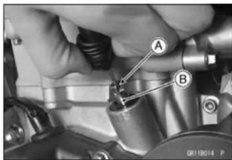
Clutch Cable Installation
- Run the clutch cable correctly (see Cable, Wire, and Hose Routing section in the Appendix chapter).
- Adjust the clutch cable (see Clutch Lever Free Play Adjustment in the Periodic Maintenance chapter).
Clutch Cable Inspection and Lubrication
- During a periodic inspection or when the cable has been removed, inspect and lubricate the cable (see Lubrication in the Periodic Maintenance chapter).
Clutch Cover and Right Engine Cover
Clutch Cover Removal
- Drain the engine oil (see Engine Oil Change in the Periodic Maintenance chapter).
- Remove the brake pedal (see Brake Pedal Removal in the Brakes chapter).
- Remove the clutch cover bolts [A] and right engine cover bolts [B], remove the clutch cover [C].
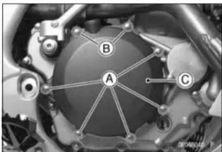
Clutch Cover Installation
- Replace the clutch cover gasket with a new one.
- Be sure to install the dowel pins.
- Apply a non-permanent locking agent to the brake pedal bolt.
• Install the clutch cover [A].
Torque - Clutch Cover Bolts [B]: 9.8 N·m (1.0 kgf·m, 87 in·lb) Right Engine Cover Bolts [C]: 9.8 N·m (1.0 kgf·m, 87 in·lb) Brake Pedal Bolt: 25 N·m (2.5 kgf·m, 18 ft·lb)
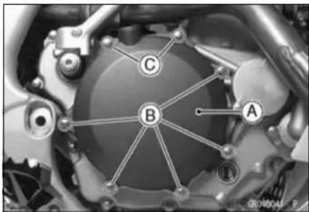
Right Engine Cover Removal
- Drain:
Engine Oil (see Engine Oil Change in the Periodic Maintenance chapter)
Coolant (see Coolant Draining in the Cooling System chapter) - Remove:
Right Engine Guard [A]
Kick Pedal [B] (see Kick Pedal Removal)
Brake Pedal [C] (see Brake Pedal Removal in the Brakes chapter)
Exhaust Pipe [D] (see Muffler Removal in the Engine Top End chapter)
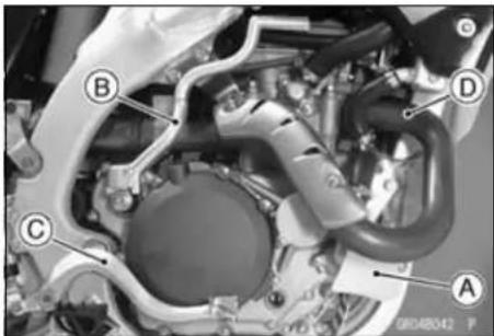
- Remove:
Water Hose [A]
Right Engine Cover Bolts [B]
Right Engine Cover [C]
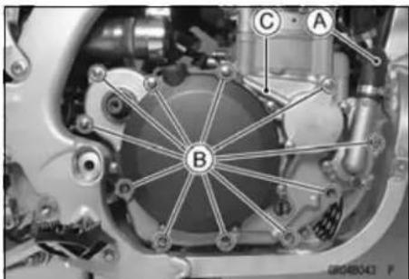
Clutch Cover and Right Engine Cover
Right Engine Cover Installation
- Three dowel pins [A] are installed at the mating surface between the crankcase and the right engine cover.
- Apply grease to the O-rings [B], and install them to the crankcase.
○Install the lower O-ring so that the tapered side facing outside.
- Replace the engine cover gasket with a new one.
- Apply a high-temperature grease to the oil seal lip of the crankshaft of the right engine cover.
- Apply a grease to the kick shaft oil seal lips and kick shaft spline.
- When installing the cover doesn't go well, the cover is installed according to the following procedures.
○Fit the water pump shaft [A] and groove [B] of the balancer shaft while turning the water pump shaft.
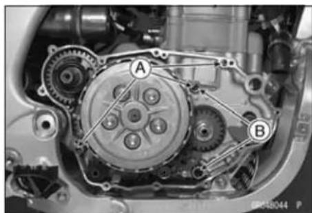
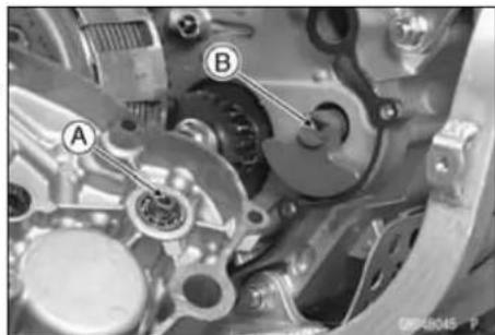
- Tighten:
Torque - Right Engine Cover Bolts: 9.8 N·m (1.0 kgf·m, 87 in·lb)
- Insert the water hose [A] into the water pump cover [B], and tighten it with the clamp [C].
• Install the kick pedal (see Kick Pedal Assy Installation).
- Install the engine oil drain plugs surely (see Engine Oil Change in the Periodic Maintenance chapter).
- Pour in the specified type and amount of oil (see Engine Oil Change in the Periodic Maintenance chapter).
- Pour in the specified type and amount of coolant (see Coolant Filling in the Cooling System chapter).
- Check the rear brake for good braking power and no brake drag.
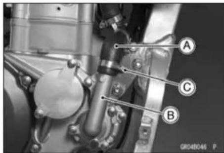
Release Shaft Removal
- Remove:
Clutch (see Clutch Removal)
Magneto Cover (see Magneto Cover Removal in the Electrical System chapter)
Magneto (see Magneto Removal in the Electrical System chapter)
- Remove the clutch cable upper end (see Clutch Cable Removal).
- Remove the tip [A] of the clutch cable (see Clutch Cable Removal).
- Remove the tip [B] of the short cable [C] from the pull rod [D].
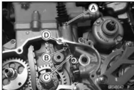
Clutch Cover and Right Engine Cover
- Turn the release lever shaft [A] and remove the short cable [B] from the lever.
- Pull the lever and shaft assembly [C] out of the crankcase.
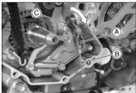
Release Shaft Installation
- Apply grease to the oil seal lips.
- Apply engine oil to the bearing in the hole of the crankcase.
- Apply molybdenum disulfide grease to the part where the push rod comes in contact.
- Insert the release shaft straight into the hole of the crankcase.
NOTICE
When inserting the release shaft, be careful not to remove the spring of the oil seal.
- Install the removed parts.
Clutch
Clutch Removal
- Drain the engine oil (see Engine Oil Change in the Periodic Maintenance chapter).
- Remove the clutch cover (see Clutch Cover Removal).
- Remove:
Clutch Spring Bolts [A]
Clutch Springs
Clutch Spring Plate [B]
- Remove:
Adjusting Washer [A]
Needle Bearing [B]
Push Rod Holder [C]
Push Rod
Friction Plates [D]
Steel Plates [E]
- Fix the clutch hub [A] with the clutch holder [B]. Special Tool - Clutch Holder: 57001-1243
- Loosen the clutch hub nut [C] counterclockwise.
- Remove:
Washer
Clutch Hub
Toothed Washer [A]
Clutch Housing [B]
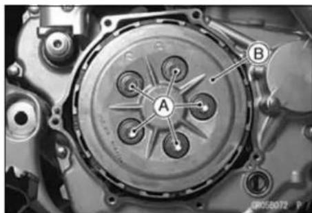
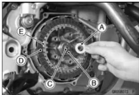
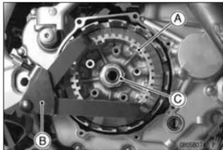
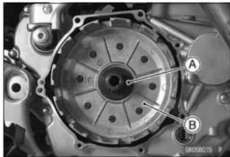
Clutch Installation
- Check the clutch plate assembly free play (see Clutch Plate Assembly Free Play Inspection/Adjustment).
- Apply molybdenum disulfide oil to the inside of the clutch housing gear.
• Install the clutch housing [A]. - Do not forget to install the toothed washer [B] before installing the clutch hub [C].
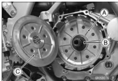
Clutch
- Install the washer so that stamp mark [A] facing the outside.
- Tighten the clutch hub nut [A] with the clutch holder [B]. Special Tool - Clutch Holder: 57001-1243
Torque - Clutch Hub Nut: 98 N·m (10 kgf·m, 72 ft·lb)
- Install the friction plates and steel plates, starting with a friction plate [A] and alter nating them. Finishing with a friction plate.
○Install the friction plates so that the width of the lining blocks [B] at the plates of the both ends are wider than the other plates.
○Apply engine oil to the new friction plates when it shall be installed.
NOTICE
If dry steel plates a nd friction plates are installed, apply engine oil to the surfaces of each plate to avoid clutch plate seizure.
- Apply molybdenum disulfide grease to the rubbing portion [A] of the push rod holder.
- Install the push rod [B] and push rod holder.
- Apply molybdenum disulfide grease to the needle bearing [C] and adjusting washer [D], and install them.
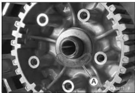
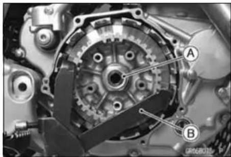
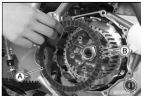
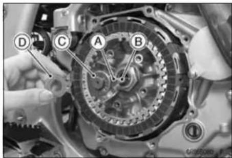
Clutch
- Tighten:
Torque - Clutch Spring Bolts [A]: 8.8 N·m (0.90 kgf·m, 78 in·lb)
- Install the clutch cover (see Clutch Cover Installation).
- Check the pull rod positions [A].
○Pulling [B] the pull rod [C] lightly upward by hand and measure the portion of the pull rod coming out.
Pull Rod Position
Standard: 9.2 \~ 14.4 mm (0.36 \~ 0.567 in.)
★If the rod position is not within the standard, select the correct thickness of adjusting washer(s) according to the tables shown.
Adjusting Washers
| Thickness Part Number | |
| 1.5 mm 92200-1548 | |
| 1.0 mm 92200-0045 | |
Pull Rod Position and Adjusting Washer Selection
| Installed Washer | Position Length | ||||||
| Washers Thickness | Qty | Less than 9.2 mm | 9.2 mm to 14.4 mm | More than 14.4mm | |||
| Change Washer Thikness | Qty | Change Washer Thikness | Qty | Change Washer Thikness | Qty | ||
| 1.0 1 | NG OK | 1.5 1 | |||||
| 1.5 1 1.0 1 | OK | 1.0 2 | |||||
| 1.0 2 1.5 1 | OK | NG | |||||
- Remove the push rod holder assy as necessary and reinstall the clutch.
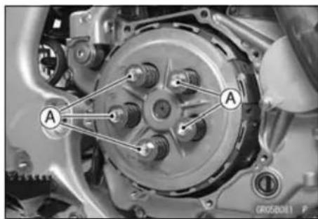
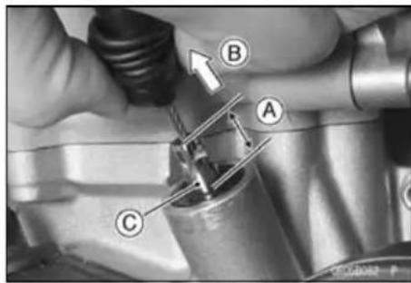
Clutch
Clutch Plate Assembly Free Play Inspection/Adjustment
- Assemble the following parts.
Clutch Hub [A]
Friction Plates [B]
Steel Plates [C]
Friction Plates [D]
Spring Plate [E]
Spring [F]
Bolts [G]
○Friction Plates [B] have lining blocks that are wider than other plates. These plates install both end of the all plates.
Torque - Clutch Spring Bolts: 8.8 N·m (0.90 kgf·m, 78 in·lb)
- Measure the clutch plate assembly [H].
Clutch Plate Assembly Length
Standard: 34.9 \~ 35.5 mm (1.37 \~ 1.40 in.)
★If clutch plate length is not within the standard, select the correct length of adjusting plates according to the table shown.
| Thickness Part Number | |
| 1.2 mm (0.047 in.) 13089-1010 | |
| 1.6 mm (0.063 in.) 13089-1095 | |
| 2.0 mm (0.079 in.) 13089-1005 |
○Do not use the steel plate of 1.2 mm (0.047 in.) and 2.0 mm (0.079 in.) thickness at the same time.
Friction and Steel Plates Wear, Damage Inspection
- Refer to the Friction and Steel Plates Inspection in the Periodic Maintenance chapter.
Friction and Steel Plate Warp Inspection
- Refer to the Friction and Steel Plate Inspection in the Periodic Maintenance chapter.
Clutch Spring Free Length Inspection
- Measure the free length [A] of the clutch springs.
★If any clutch spring is shorter than the service limit, it must be replaced.
Clutch Spring Free Length
Standard: 49.2 mm (1.94 in.)
Service Limit: 46.7 mm (1.84 in.)
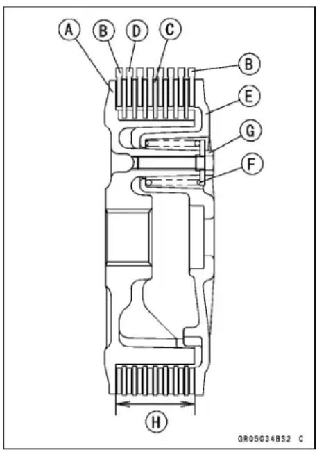
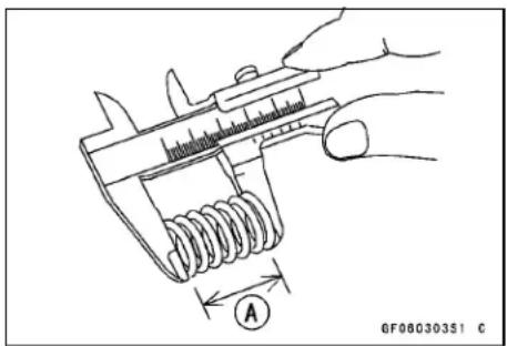
Clutch
Clutch Housing Finger Damage
- Visually inspect the clutch housing fingers [A] that come in contact with the friction plate tangs.
★If they are damaged or if there are groove cuts in the areas that come in contact with the tangs, replace the housing. Replace the friction plates if their tangs are damaged as well.
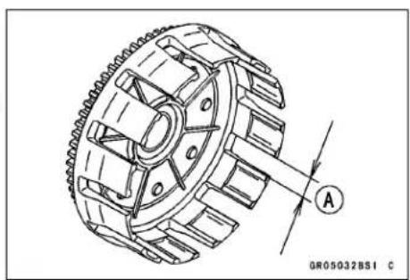
Friction Plate/Clutch Housing Clearance
- Measure the clearance between the tangs [A] on the friction plate and the fingers [B] of the clutch housing.
★If this clearance is excessive, the clutch will be noisy.
★If the clearance exceeds the service limit, replace the friction plates.
Friction Plate/Clutch Housing Clearance
Standard: 0.20 \~ 0.60 mm (0.0079 \~ 0.024 in.)
Service Limit: 0.8 mm (0.03 in.)
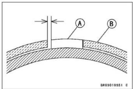
Clutch Hub Spline Damage
- Visually inspect the areas of the clutch hub splines that come in contact with the teeth of the steel plates.
★If there are notches worn into the clutch hub splines [A], replace the clutch hub. Replace the steel plates if their teeth are damaged as well.
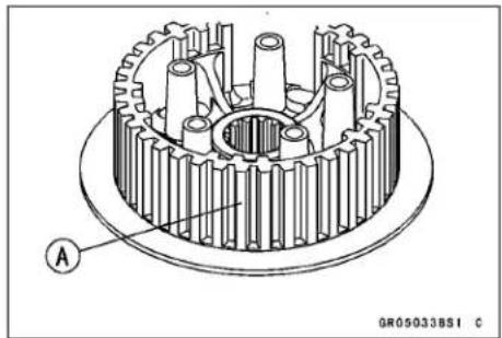
Primary Gear
Primary Gear Removal
- Remove:
Right Engine Cover (see Right Engine Cover Removal) Clutch (see Clutch Removal) - Temporarily install the clutch housing [A].
- Using the gear holder [B], secure the primary gear and loosen the primary gear nut.
Special Tool - Gear Holder, m2.0: 57001-1557
- Remove the clutch housing.
- Remove the primary gear nut [C], washer, primary gear [D] and oil pump drive gear.
○Primary gear nut is left-hand threads.
Primary Gear Installation
- Insert the oil pump drive gear [A] and primary gear [B] to the crankshaft.
• Install the washer [C] as shown.
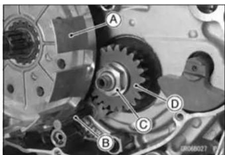
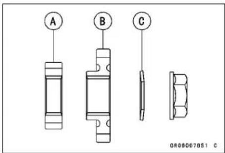
- Replace the primary gear nut [A] with a new one.
- Using the gear holder [B], secure the clutch gear and the bottom of the primary gear; then, tighten the primary gear nut.
○Primary gear nut is left-hand threads.
Torque - Primary Gear Nut: 98 N·m (10 kgf·m, 72 ft·lb)
Special Tool - Gear Holder, m2.0: 57001-1557
- Install: Clutch (see Clutch Installation) Right Engine Cover (see Right Engine Cover Installation)
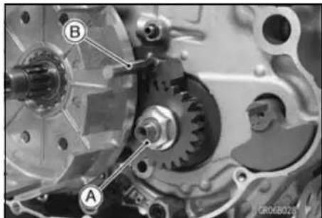
External Shift Mechanism
External Shift Mechanism Removal
- Remove: Shift Pedal Bolt [A] Shift Pedal [B]
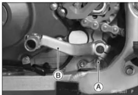
- Remove: Right Engine Cover (see Right Engine Cover Removal) Clutch Housing (see Clutch Removal) Circlip [A] Oil Pump Driven Gear [B]
- Pull out the shift shaft [C]. - Remove the bolt [D] and screw [E], take off the shift ratchet assembly [F] with ratchet plate [G].
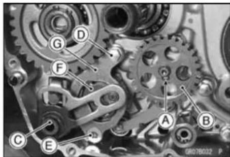
- Remove the bolt [A] and shift dram cam [B]. - Remove the nut [C], and take off the gear set lever [D].
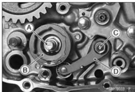
External Shift Mechanism Installation
- Install the gear set lever [A]. ○Fit each end of the spring [B] or original positions. ○Do not forget to install the color and washer [C]. - Tighten the gear set lever nut [D].
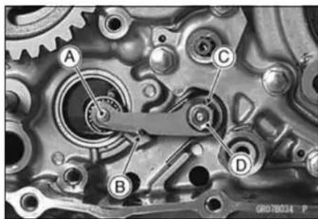
Torque - Gear Set Lever Nut: 8.8 N·m (0.90 kgf·m, 78 in·lb)
- Holding the gear set lever [A] with the (−) driver [B] and install the shift dram cam [C]. ○Apply a non-permanent locking agent to the shift dram cam bolt. ○Fit the groove [D] on the pin [E]. - Align the roller of the gear set lever with the slot of the shift dram cam.

External Shift Mechanism
- Set up the shift ratchet assembly as shown in the figure. Ratchet [A]
Pawls [B]
Pins [C]
Springs [D]
○Assembly the shift ratchet so that groove [E] of the pawl facing the crankcase side [F].
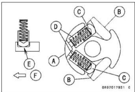
- Then install the ratchet assembly [A] to the ratchet plate [B] as shown in the figure.
• Install the ratchet assembly to the shift drum cam. - Apply a non-permanent locking agent to the ratchet plate mounting screw.
- Tighten the screw first, and tighten the bolt.
- Tighten:
Torque - Ratchet Plate Mounting Screw: 6.4 N·m (0.65 kgf·m, 56 in·lb)
Ratchet Plate Mounting Bolt: 9.8 N·m (1.0 kgf·m, 87 in·lb)
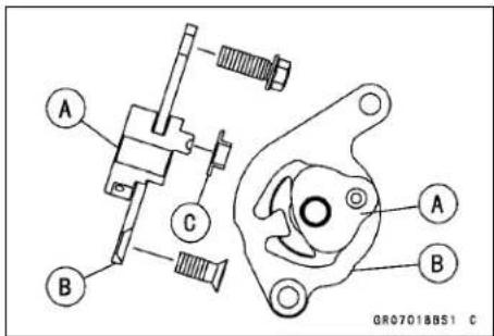
- Apply grease to the collar [C] and install it.
- Before installing the shift shaft, apply high temperature grease to the oil seal lips and shift shaft splines.
- Insert the shift shaft [A].
- Replace the circlip [B] with a new one.
- Install:
Oil Pump Driven Gear [C]
Circlip
Clutch (see Clutch Installation)
Right Engine Cover (see Right Engine Cover Installation)
- Install the shift pedal so that the split portion [A] on the pedal and punch mark [B] on the shift align.
- Tighten:
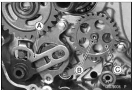
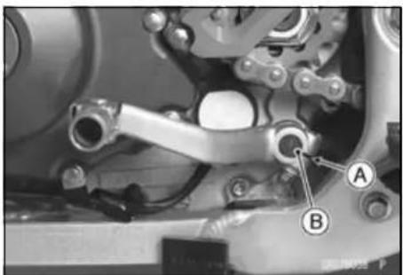
External Shift Mechanism Inspection
- Check the shift shaft [A] for bending or damage to the splines.
★If the shaft is bent, straighten or replace it. If the splines are damaged, replace the shift mechanism. - Check the return spring [B] for cracks or distortion.
★If the spring is damaged in any way, replace it. - Check the shift lever [C] for distortion.
★If the shift lever is damaged in any way, replace the shift shaft.
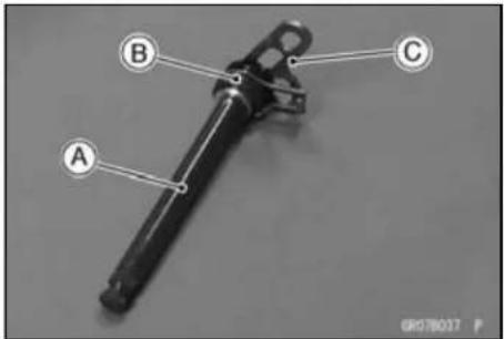
External Shift Mechanism
- Check the ratchet assembly for damage.
★If ratchet [A], pawls [B], pins [C] or springs [D] are damaged in any way, replace them.

- Check the gear set lever [A] and its spring [B] for cracks or distortion.
★If the lever or spring is damaged in any way, replace them.
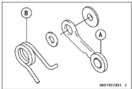
- Visually inspect the shift drum cam [A].
★If it is badly worn or if it shows any damage, replace it.
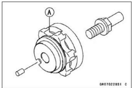
Kick Pedal Assy Removal
- Remove: Mounting Bolt [A] Kick Pedal Assy [B]
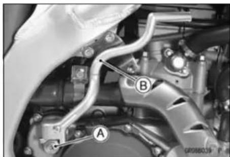
Kick Pedal Assy Installation
- Install the kick pedal assy [A] at the angle shown. 17 \~ 27 mm (0.67 \~ 1.1 in.) [B]
- Apply a non-permanent locking agent to the kick pedal bolt.
- Tighten: Torque - Kick Pedal Bolt: 25 N·m (2.5 kgf·m, 18 ft·lb)
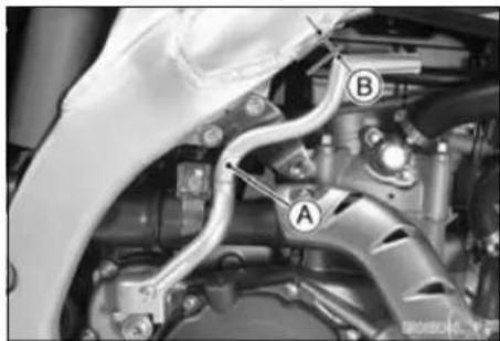
Kick Pedal Assy Disassembly
- Remove the kick pedal assy.
- Remove: Plug Screw [A] Spring [B] Steel Ball [C] Detente Screw [D] Oil Seal [E]
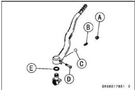
Kick Pedal Assy Assembly
- Apply grease to the steel ball, oil seal lip, spring, and the sliding portion of the lever.
- After tightening the screws stake it with a punch.
Idle Gear Removal
- Remove: Clutch Cover (see Clutch Cover Removal) Clutch Housing (see Clutch Removal) Circlip [A] Idle Gear [B]
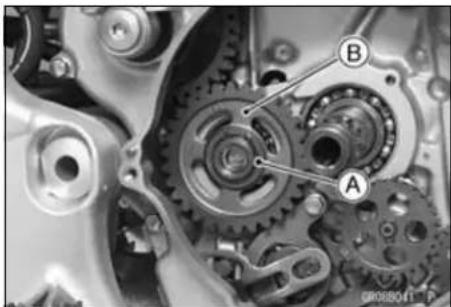
Kickstarter
Idle Gear Installation
- Apply engine oil to the inside of the idle gear.
- Replace the circlip [A] with a new one.
- Install the idle gear [B] facing embossed letter [C] to the outside.
- Install the circlip.
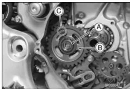
Kickshaft Removal
- Remove: Right Engine Cover (see Right Engine Cover Removal) Clutch Housing (see Clutch Removal)
- Pull the end [A] of the kick spring [B] out of the hole in the crankcase.
- Turn the kickshaft counterclockwise [C] and pull out the kickstarter assembly [D].
- Remove the bolt [A], take off the ratchet guide [B].
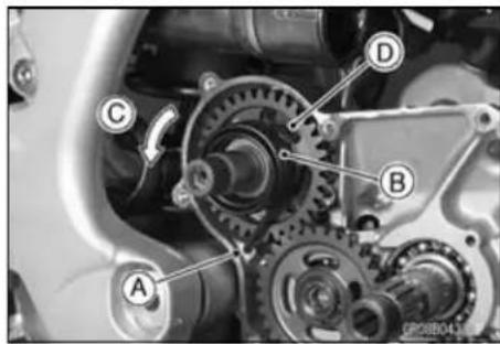

Kickshaft Installation
- Install the ratchet guide [A]. Torque - Ratchet Guide Bolt: 8.8 N·m (0.90 kgf·m, 78 in·lb)
- Apply molybdenum disulfide grease to the end of the kickshaft.
- Insert the kick shaft assembly [B] into the crankcase. ○Securely engage the stopper portion [C] of the ratchet gear with the guide.
- Insert the spring end [D] into the hole [E].
- Install: Clutch Housing (see Clutch Installation) Right Engine Cover (see Right Engine Cover Installation)
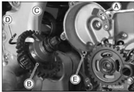
Kickstarter
Kick Shaft Assembly Disassembly/Assembly
● The kick shaft assembly consists of the following parts.
[A] Kick Gear
[B] Circlip
[C] Washer
[D] Spring
[E] Ratchet Gear
[F] Kick Shaft
[G] Kick Spring
[H] Spring Guide
- Check the kick shaft assembly parts for damage.
★Any damaged parts should be replaced with new ones. - Apply molybdenum disulfide oil to the inside of the kick gear and ratchet gear.
- Apply grease to the inside of the spring guide.
- When assembling the ratchet gear [A] onto the kick shaft [B], align the punch mark [C] on the ratchet gear with the punch mark [C] on the kick shaft.
- Replace the circlips that were removed with new ones.
Special Tool - Outside Circlip Pliers: 57001-144
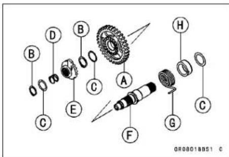
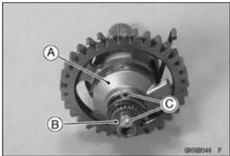
Engine Lubrication System
Table of Contents
Exploded View 7-2
Lubrication System Chart 7-4
Specifications 7-6
Special Tools 7-7
Engine Oil and Oil Filter 7-8
Engine Oil Level Inspection 7-8
Engine Oil Change 7-8
Oil Filter Change 7-9
Oil Screen 7-10
Oil Screen (Scavenge) Removal 7-10
Oil Screen (Scavenge) Installation 7-10
Oil Screen (Feed) Removal 7-11
Oil Screen (Feed) Installation 7-11
Oil Screen (Scavenge) Cleaning 7-11
Oil Screen (Feed) Cleaning 7-12
Oil Pressure Relief Valve 7-13
Oil Pressure Relief Valve Removal 7-13
Oil Pressure Relief Valve Installation 7-13
Oil Pressure Relief Valve Inspection.... 7-13
Oil Pump 7-14
Oil Pump (Scavenge) Removal 7-14
Oil Pump (Scavenge) Installation 7-14
Oil Pump (Feed) Removal 7-15
Oil Pump (Feed) Installation 7-15
Oil Pump Inspection 7-16
Oil Pressure 7-17
Oil Pressure Measurement 7-17
7-2 ENGINE LUBRICATION SYSTEM
Exploded View
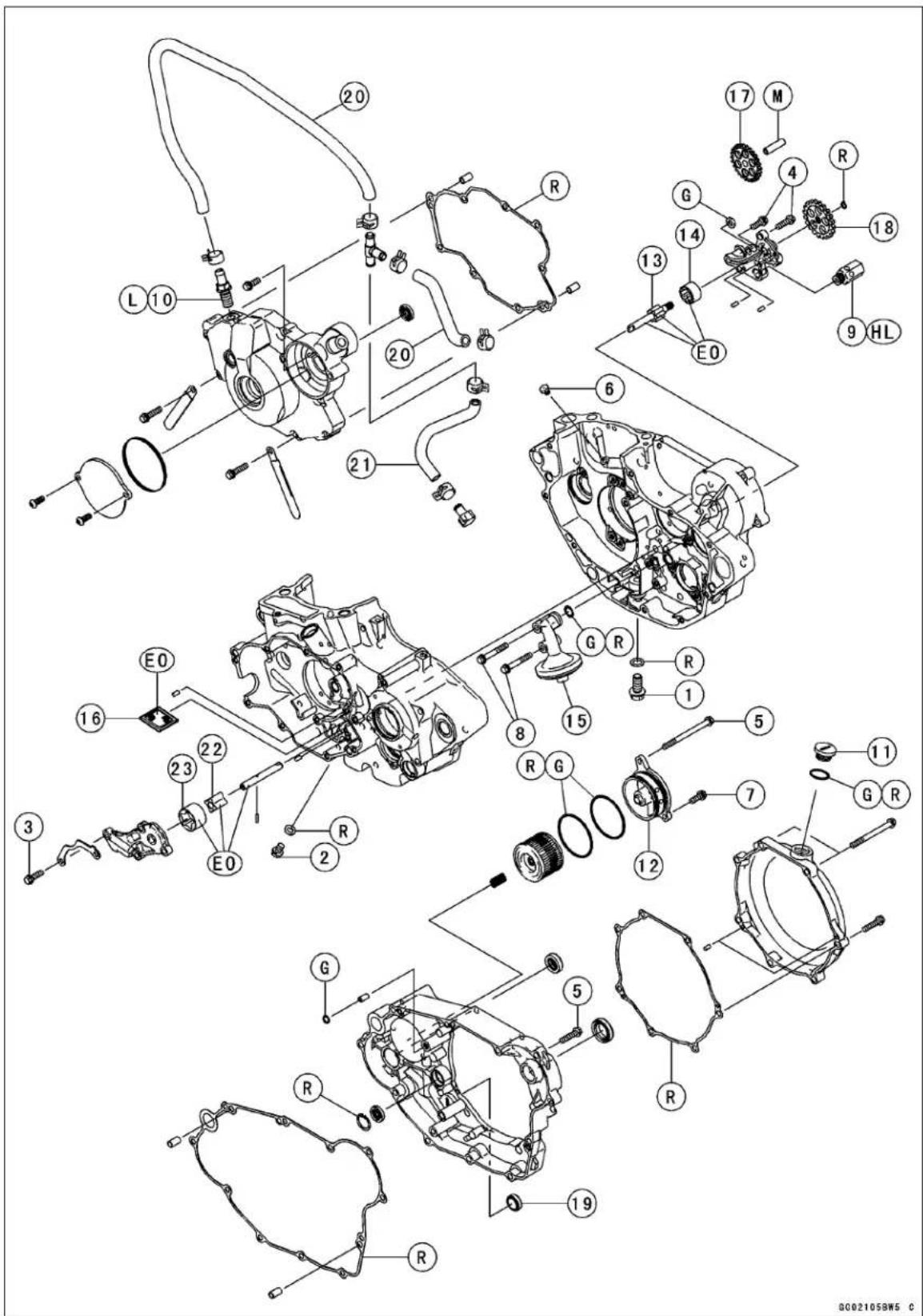
Exploded View
| No. | Fastener | Torque | Remarks | ||
| N·m kgf·m ft·lb | |||||
| 1 | Engine Oil Drain Plug (M10) (Main) | 20 | 2.0 | 15 | |
| 2 | Engine Oil Drain Plug (M6) (Sub) | 7.0 | 0.71 | 62 in·lb | |
| 3 | Oil Pump (Scavenge) Cover Bolts | 9.8 | 1.0 | 87 in·lb | |
| 4 | Oil Pump (Feed) Cover Bolts | 9.8 | 1.0 | 87 in·lb | |
| 5 | Right Engine Cover Bolts | 9.8 | 1.0 | 87 in·lb | |
| 6 | Piston Oil Nozzle | 5.0 | 0.50 | 44 in·lb | |
| 7 | Oil Filter Cover Bolt | 9.8 | 1.0 | 87 in·lb | |
| 8 | Oil Screen (Feed) Mounting Bolts | 9.8 | 1.0 | 87 in·lb | |
| 9 | Oil Pressure Relief Valve | 15 1.5 | 11 | HL | |
| 10 | Breather Fitting | 15 | 1.5 | 11 | L |
| 11 | Oil Filler Cap | - | - | - | Hand-tighten |
- Oil Filter Cover
- Inner Rotor (feed)
- Outer Rotor (feed)
- Oil Screen (Feed)
- Oil Screen (Scavenge)
- Oil Pump Idle Gear
- Oil Pump Gear
- Oil Level Gauge
- Breather Hose
- Drain Hose
- Inner Rotor (Scavenge)
- Outer Rotor (Scavenge)
EO: Apply engine oil.
G: Apply grease.
HL: Apply high-locking agent.
L: Apply a non-permanent locking agent.
M: Apply molybdenum disulfide grease.
R: Replacement Parts
7-4 ENGINE LUBRICATION SYSTEM
Lubrication System Chart
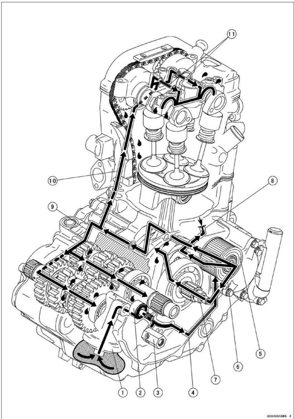
Lubrication System Chart
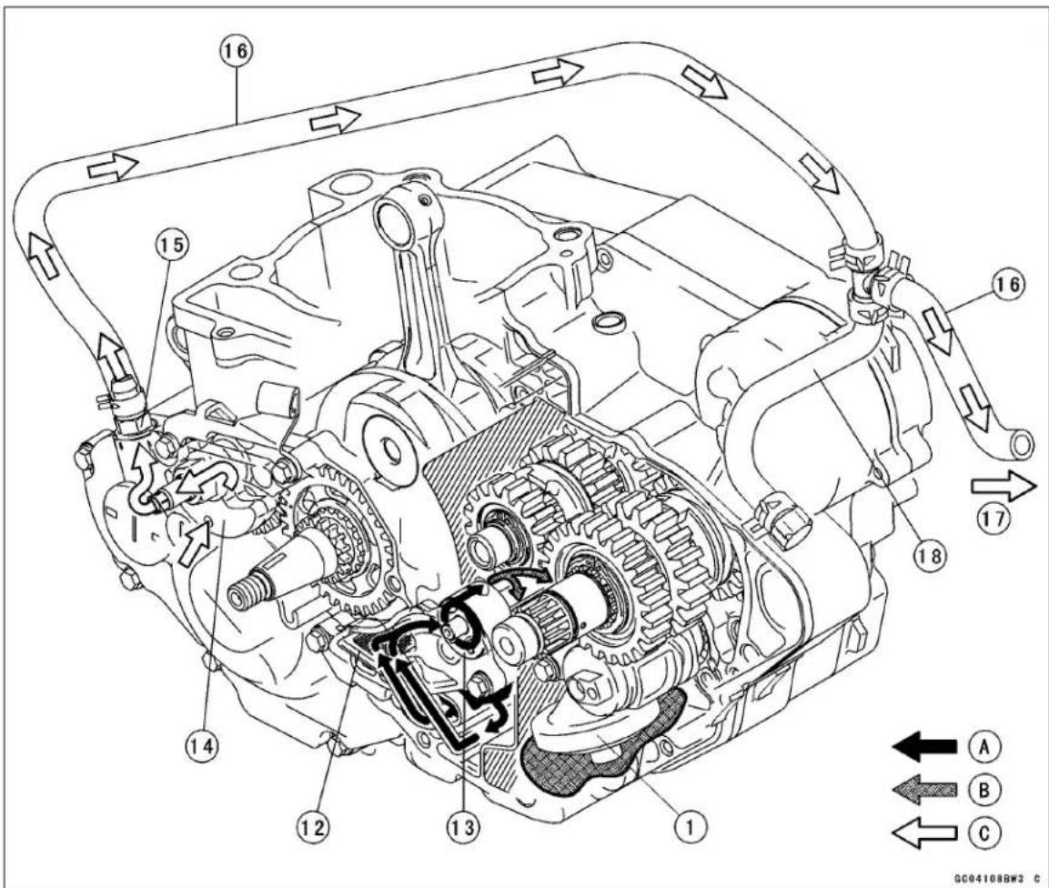
- Oil Screen (feed)
- Oil Pump (feed)
- Oil Pressure Relief Valve
- Right Engine Cover Oil Passage (from Feed Oil Pump to Oil filter)
- Oil Filter
- Right Engine Cover Oil Passage (from Oil filter to Crankshaft)
- Crankshaft
- Piston Oil Nozzle
- Left Crankcase Oil Passage (from Oil filter to Transmission Oil Passage)
- Cylinder Oil Passage (from Crankcase Oil Passage to Cylinder Head Oil Passage)
- Oil Pipes
- Oil Screen (scavenge)
- Oil Pump (scavenge)
- Balancer Weight
- Fitting
- Breather Hose
- To Air Cleaner Housing
- Drain Hose
A: Crank Room Oil
B: Transmission Room Oil
C: Blowby Gas
7-6 ENGINE LUBRICATION SYSTEM
Specifications
| Item Standard | |
| Engine OilTypeViscosity SAE 10W-40CapacityOil Change - when filter is not removedOil Change - when filter is removedwhen engine is completely dryOil Level (after warm-up or driving) | API SG, SH, SJ, SL or SM with JASO MA, MA1 or MA21.06 L (1.12 US qt)1.08 L (1.14 US qt)1.3 L (1.4 US qt)Upper level |
| Oil Pressure Measurement(oil temperature 90°C, engine speed 4 000 rpm) | 39 ~ 98 kPa (0.4 ~ 1.0 kgf/cm2, 5.6 ~ 14 psi) |
Special Tools
Oil Pressure Gauge, 5 kgf/cm²: 57001-125
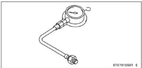
Outside Circlip Pliers: 57001-144

Oil Pressure Gauge Adapter, M10 × 1.25: 57001-1182
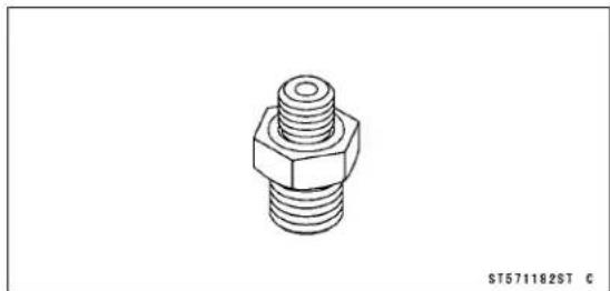
Oil Pressure Cap: 57001-1656
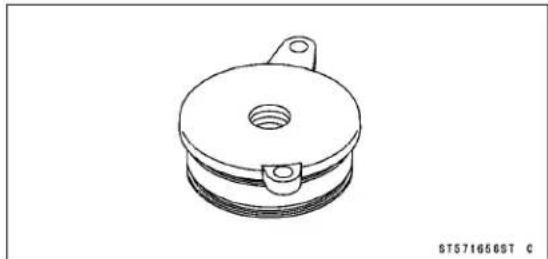
7-8 ENGINE LUBRICATION SYSTEM
Engine Oil and Oil Filter
WARNING
Vehicle operation with insufficient, deteriorated, or contaminated engine oil will cause accelerated wear and may result in engine seizure, accident, and injury. Check the oil level before each use and change the oil and filter according to the periodic maintenance chart.
The engine oil level indicated in the right engine cover oil level gauge is very sensitive to the motorcycle's position and engine rpm at time of shut down. Because of the semi-dry sump lubrication system with separate oil chambers in the crank room and transmission room, under certain conditions oil can accumulate in the crank room and give a false low reading at the oil level gauge, which indicates oil volume in the transmission room.
Engine Oil Level Inspection
- Situate the motorcycle so that it is vertical.
- Check that the engine oil level is between the upper [A] and lower levels [B] in the gauge.
NOTE
○ Situate the motorcycle so that it is perpendicular to the ground.
○ If no oil appears in the gauge, tip the motorcycle slightly to the right until oil is visible then return to an upright position. If no oil appears even when tipped at an extreme angle, remove both drain bolts to empty any oil that may be in the transmission and crankcase, reinstall the drain bolts and refill with the specified amount of oil.
○ If the motorcycle has just been used, wait several minutes for all the oil to drain down.
○ If the oil has just been changed, start the engine and run it for several minutes at idle speed. This fills the oil filter with oil.
○Do not run the engine at high engine speed. Stop the engine, then wait several minutes until the oil settles.
NOTICE
Racing the engine before the oil reaches every part can cause engine seizure.
★If the oil level is too high, remove the excess oil through the filler opening, using a syringe or some other suitable device.
★If the oil level is too low, add the correct amount of oil through the oil filler opening. Use the same type and make of oil that is already in the engine.
NOTE
○If the engine oil type and make are unknown, use any brand of the specified oil to top off the level rather than running the engine with the oil level low. Then at your earliest convenience, change the oil completely.
Engine Oil Change
- Refer to the Engine Oil Change in the Periodic Maintenance chapter.
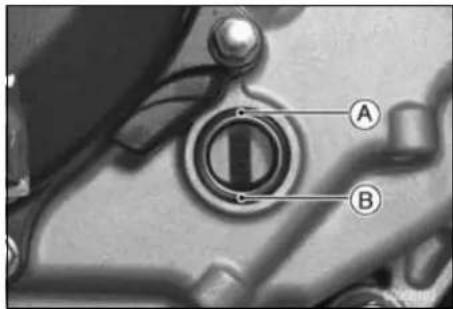
Engine Oil and Oil Filter
Oil Filter Change
- Refer to the Oil Filter Change in the Periodic Maintenance chapter.
7-10 ENGINE LUBRICATION SYSTEM
Oil Screen
Oil Screen (Scavenge) Removal
- Remove the oil pump (scavenge) cover (see Oil Pump (Scavenge) Removal).
- Pull out the oil screen [A] from the crankcase.
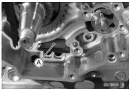
Oil Screen (Scavenge) Installation
- Clean the oil screens thoroughly whenever it is removed for any reason.
- Clean the oil screens with a high-flash point solvent and remove any particles stuck to them.
WARNING
Gasoline and low-flash point solvents can be flammable and/or explosive and cause severe burns. Clean the screens in a well-ventilated area, and take care that there are no sparks or flame anywhere near the working area; this includes any appliance with a pilot light. Do not use gasoline or a low-flash point solvent to clean the screens.
NOTE
○ While cleaning the screens, check for any metal particles that might indicate internal engine damage.
- Check the screen [A] carefully for any damage, holes, broken wires, gasket pulling off.
★If the screen is damaged, replace it.
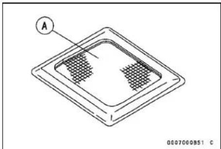
- Apply engine oil to the rubber portion [A] on the oil screen.
- Install the oil screen facing the carved line [B] to the outside.
- Install the oil pump (scavenge) cover (see Oil Pump (Scavenge) Installation).

Oil Screen
Oil Screen (Feed) Removal
- Split the crankcase (see Crankcase Disassembly in the Crankshaft/Transmission chapter).
- Remove: Bolts [A] Oil Screen [B]
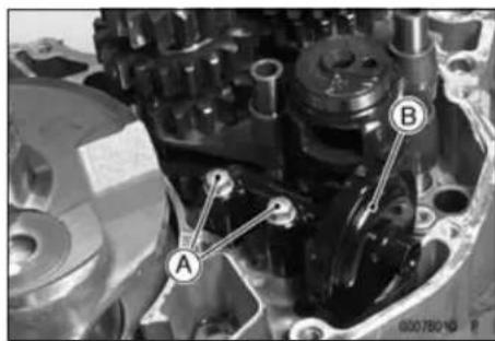
Oil Screen (Feed) Installation
- Replace the O-ring [A] with a new one.
- Apply grease to the O-ring, and install it.
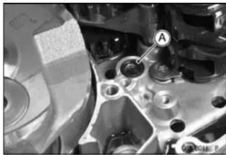
- Install the oil screen [A], and tighten the bolts [B] Torque - Oil Screen (Feed) Mounting Bolts: 9.8 N·m (1.0 kgf·m, 87 in·lb)
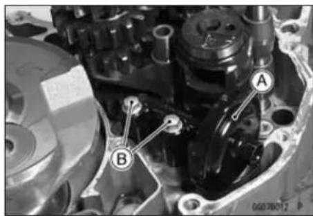
Oil Screen (Scavenge) Cleaning
- Remove the oil screen (see Oil Screen (Scavenge) Removal).
- Clean the oil screen with a high-flash point solvent and remove any particles stuck to them.
WARNING
Gasoline and low-flash point solvents can be flammable and/or explosive and cause severe burns. Clean the screens in a well-ventilated area, and take care that there are no sparks or flame anywhere near the working area; this includes any appliance with a pilot light. Do not use gasoline or a low-flash point solvent to clean the screens.
7-12 ENGINE LUBRICATION SYSTEM
Oil Screen
- Check the screen [A] carefully for any damage, holes, broken wires gasket pulling off.
★If the screen is damaged, replace it. - Install the oil screen (see Oil Screen (Scavenge) Installation).
Oil Screen (Feed) Cleaning
- Remove the oil screen (see Oil Screen (Feed) Removal).
- Clean the oil screen with a high-flash point solvent and remove the particles stuck.
- Blow away the particles by applying compressed air [A] from the inside to the outside (from the clean side to the dirty side).
WARNING
Gasoline and low-flash point solvents can be flammable and/or explosive and cause severe burns. Clean the screen in a well-ventilated area, and take care that there are no sparks or flame anywhere near the working area; this includes any appliance with a pilot light. Do not use gasoline or a low-flash point solvent to clean the screen.
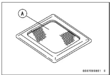
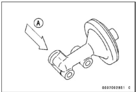
NOTE
○ While cleaning the screens, check for any metal particles that might indicate internal engine damage.
- Check the screen carefully for any damage, holes, and broken wires.
★If the screen is damaged, replace the oil screen.
Oil Pressure Relief Valve
Oil Pressure Relief Valve Removal
- Remove:
Right Engine cover (see Right Engine Cover Removal in the Engine Right Side chapter)
Clutch (see Clutch Removal in the Engine Right Side chapter)
- Remove the oil pressure relief valve [A].
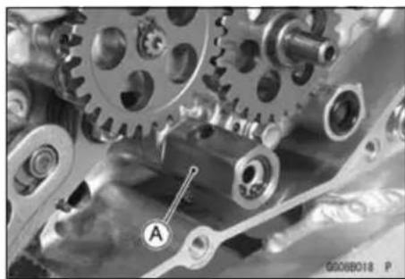
Oil Pressure Relief Valve Installation
- Apply high-locking agent to the threads of oil pressure relief valve, and tighten it.
Torque - Oil Pressure Relief Valve: 15 N·m (1.5 kgf·m, 11 ft·lb)
Oil Pressure Relief Valve Inspection
- Remove the relief valve (see Oil Pressure Relief Valve Removal).
- Using a wooden stick, push the inner valve to make sure that the valve [A] moves smoothly and that it returns to its original position by the force of the spring [B].
NOTE
○ The relief valve cannot be disassembled and it must be inspected in the assembled state.
★If the valve movement is not smooth, wash the relief valve with high-flash point solvent, and use compressed air to remove any foreign particles from it.
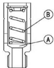
G0080602S1 C
WARNING
Gasoline and low-flash point solvents can be flammable and/or explosive and cause severe burns. Clean the oil pressure relief valve in a well-ventilated area, and take care that there are no sparks or flame anywhere near the working area; this includes any appliance with a pilot light. Do not use gasoline or a low-flash point solvent to clean the oil pressure relief valve.
★If the valve does not move smoothly even after washing it, replace the relief valve. The oil pressure relief valve is precision made with no allowance for replacement of individual parts.
7-14 ENGINE LUBRICATION SYSTEM
Oil Pump
Oil Pump (Scavenge) Removal
- Drain:
Engine Oil (see Engine Oil Change in the Periodic Maintenance chapter) Coolant (see Coolant Draining in the Coolant System chapter)
- Remove:
Shift Pedal (see External Shift Mechanism in the Engine Right Side chapter) Flywheel (see Flywheel Removal in the Electrical System chapter)
- Remove:
Oil Pump Cover Bolts [A] Lower Camshaft Chain Guide [B] Oil Pump Cover [C]
- Remove:
Inner Rotor [A] Outer Rotor [B]
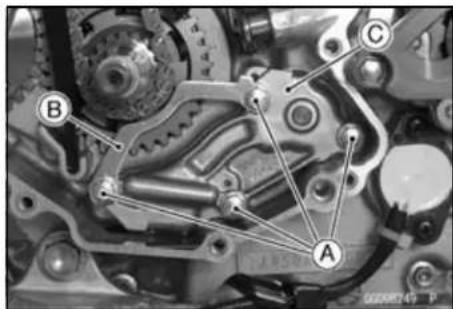
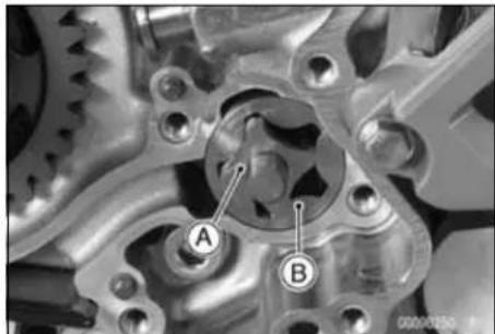
Oil Pump (Scavenge) Installation
- Install the dowel pins [A] to the crankcase.
- Apply engine oil to the each oil pump rotor and sliding surface of the oil pump shaft.
• Install: Outer Rotor [B] Inner Rotor [C]
○While turn the oil pump shaft, install the oil pump so that the left and right oil pump shaft may mesh in the crankcase.
• Install: Oil Pump Cover [A] Lower Camshaft Chain Guide [B]
- While pushing the oil pump cover, tighten the oil pump cover bolts [C].
Torque - Oil Pump (Scavenge) Cover Bolts: 9.8 N·m (1.0 kgf·m, 87 in·lb)
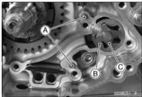
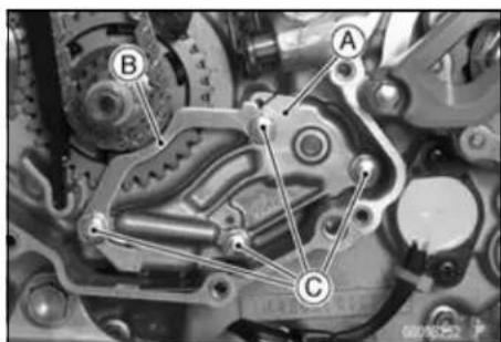
Oil Pump
Oil Pump (Feed) Removal
- Remove:
Right Engine Cover (Right Engine Cover Removal in the Engine Right Side chapter)
Clutch (Clutch Removal in the Engine Right Side chapter)
Circlip [A]
Oil Pump Driven Gear [B]
Shaft [C]
Oil Pump Idle Gear [D]
- Remove:
Oil Pump Cover Bolts [A]
Oil Pump Cover [B]
- Remove:
Inner Rotor [A]
Outer Rotor [B]
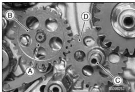
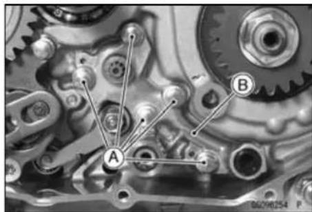
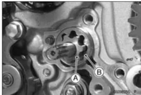
Oil Pump (Feed) Installation
- Install the dowel pins [A] to the crankcase.
- Apply engine oil to the each oil pump rotor and sliding surface of the oil pump shaft.
- Install:
Outer Rotor [B]
Inner Rotor [C]
- While turn the oil pump shaft, install the oil pump so that the left and right oil pump shaft may mesh in the crankcase.
• Install the oil pump cover [A]. - While pushing the oil pump cover, tighten the oil pump cover bolts [B].
Short Bolts [C]
Torque - Oil Pump (Feed) Cover Bolts: 9.8 N·m (1.0 kgf·m, 87 in·lb)
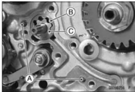
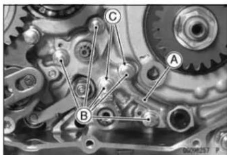
7-16 ENGINE LUBRICATION SYSTEM
Oil Pump
- Apply molybdenum disulfide grease to the oil pump idle gear shaft [A].
- Install the oil pump idle gear [B] facing the stepped side [C] to the outside.
- Replace the circlip [D] with a new one.
• Install the oil pump driven gear [E] and circlip.
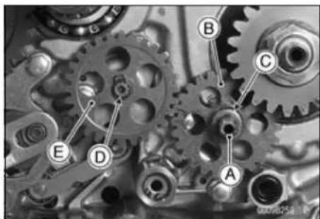
Oil Pump Inspection
- Remove the oil pump.
- Visually inspect the oil pump body, outer rotors and the inner rotors.
★If the oil pump is any damaged or unevenly worn, replace the rotors, cover, or body, or the crankcase.
Oil Pressure
Oil Pressure Measurement
- Remove:
Exhaust Pipe (see Muffler Removal in the Engine Top End chapter)
Right Engine Cover Bolt [A]
Oil Filter Cover Bolt [B]
Oil Filter Cover [C]
- Install the O-rings to the oil pressure cap.
Special Tool - Oil Pressure Cap: 57001-1656
• Install the oil pressure cap.
- Attach the oil pressure gauge adapter [A] and oil pressure gauge [B].
Special Tools - Oil Pressure Gauge Adapter, M10 × 1.0: 57001-1182
Oil Pressure Gauge, 5 kgf/cm²: 57001-125
- Start the engine and warm up the engine thoroughly.
- Run the engine at the specified speed, and read the oil pressure gauge.
★If the oil pressure is much lower than the standard, check the feed oil pump.
★If the reading is much higher than the standard, check the oil filter first, and oil passages for dirt or clogging.
Oil Pump Pressure (oil temperature 90°C, @4 000 rpm) Standard: 39 \~ 98 kPa (0.4 \~ 1.0 kgf/cm², 5.6 \~ 14 psi)
NOTE
○ Warm up the engine thoroughly before measuring the oil pressure.
- Stop the engine and remove the oil pressure cap, oil pressure gauge adapter and gauge.
WARNING
Hot oil can cause severe burns. Beware of hot engine oil that will drain through the oil passage when the oil pressure gauge adapter is removed.
• Install the oil filter cover.
Torque - Oil Filter Cover Bolt: 9.8 N·m (1.0 kgf·m, 87 in·lb) Right Engine Cover Bolts: 9.8 N·m (1.0 kgf·m, 87 in·lb)
- Install the exhaust pipe (see Muffler Installation in the Engine Top End chapter).
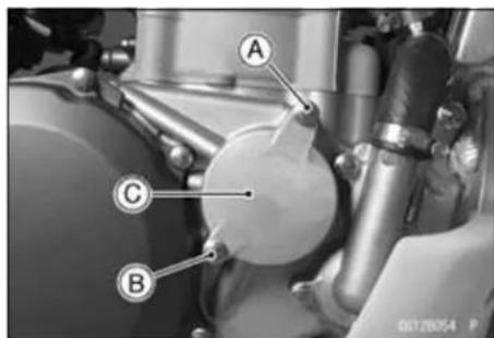
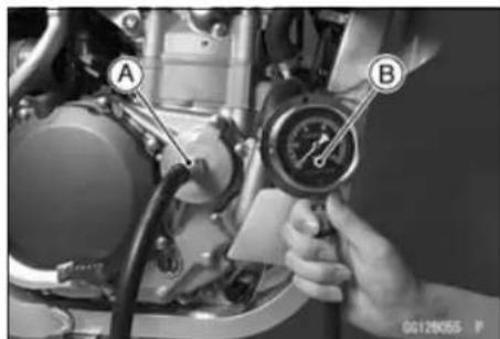
Engine Removal/Installation
Table of Contents
Exploded View 8-2
Special Tool 8-4
Engine Removal/Installation 8-5
Engine Removal 8-5
Engine Installation.... 8-8
8-2 ENGINE REMOVAL/INSTALLATION
Exploded View
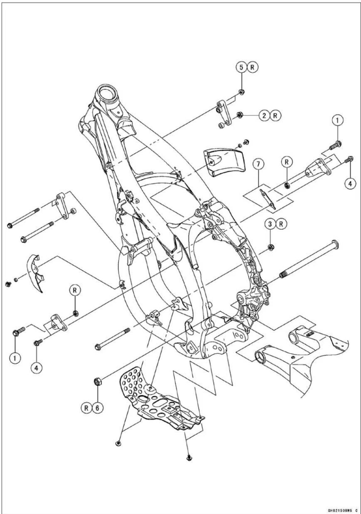
Exploded View
| No. | Fastener | Torque | Remarks | ||
| N·m kgf | ·m ft·lb | ||||
| 1 | Upper Engine Mounting Bolts (M10) | 49 | 5.0 | 36 | |
| 2 | Middle Engine Mounting Nut (M10) | 49 | 5.0 | 36 | R |
| 3 | Lower Engine Mounting Nut (M10) | 49 | 5.0 | 36 | R |
| 4 | Upper Engine Bracket Bolts (M8) | 29 | 3.0 | 21 | |
| 5 | Middle Engine Bracket Nuts (M8) | 29 | 3.0 | 21 | R |
| 6 | Swingarm Pivot Shaft Nut | 98 | 10 | 72 | R |
- KLX450A8F Model
R: Replacement Parts
8-4 ENGINE REMOVAL/INSTALLATION
Special Tool
Jack:
57001-1238
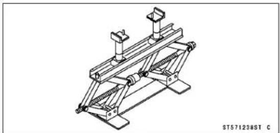
Engine Removal/Installation
Engine Removal
- Place the jack [A] under the frame to support the motorcycle.
Special Tool - Jack: 57001-1238
WARNING
When the swingarm pivot shaft is removed the swingarm and rear wheel assembly will become detached and allow the frame to fall to the floor, creating the potential for injury. Removing the engine requires the swingarm pivot to be removed, so support the bottom of the frame with a jack or other appropriate stand.
- Squeeze the brake lever slowly and hold it with a band [A].
WARNING
Motorcycle may fall over unexpectedly resulting in an accident or injury. Be sure to hold the front brake when removing the engine.
NOTICE
Be sure to hold the front brake when removing the engine, or the motorcycle may fall over. The engine or the motorcycle could be damaged.
- Drain:
Engine Oil (see Engine Oil Change in the Periodic Maintenance chapter)
Coolant (see Coolant Draining in the Cooling system chapter)
- Remove the mounting bolt [A] and remove the engine guard [B].
- Remove:
Seat (see Seat Removal in the Frame chapter)
Side Covers (see Side Cover Removal in the Frame chapter)
Fuel Tank (see Fuel Tank Removal in the Fuel System chapter)
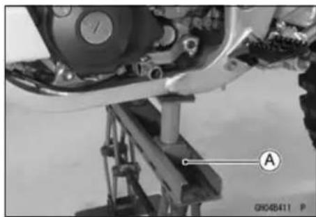
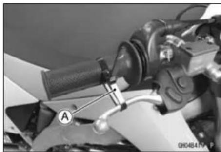
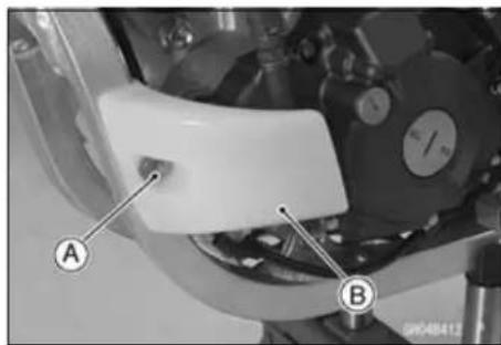
8-6 ENGINE REMOVAL/INSTALLATION
Engine Removal/Installation
- Remove:
Radiator (see Radiator Removal in the Cooling System chapter)
Muffler (see Muffler Removal in the Engine Top End chapter)
Air Cleaner Housing with Rear Frame (see Air Cleaner Housing Removal in the Fuel System chapter)
Starter Motor (see Stater Motor Removal in the Electrical System chapter)
Carburetor (see Carburetor Removal in the Fuel System chapter)
Clutch Cable Lower End [A]
Drive Chain (see Drive Chain Removal in the Final Drive chapter)
Shift Pedal (see External Shift Mechanism Removal in the Engine Right Side chapter)
Vacuum Switch Valve (see Vacuum Switch Valve Removal in the Engine Top End chapter)(equipped models)
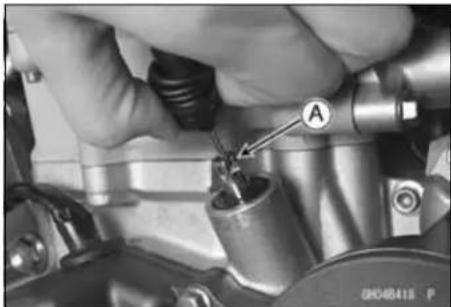
- Remove:
Bolts [A]
Rear Brake Pedal [B]
Master Cylinder [C]
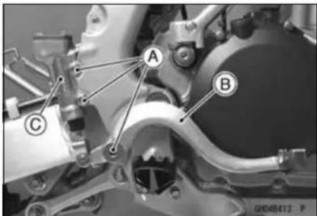
- Pry open the clamps [A].
- Disconnect:
Magnet Lead Connector [B]
Ignition Coil Lead Connector [C]
- Remove:
Breather Hose [D]
Spark Plug Cap
Ignition Coil (Ignition Coil Removal in the Electrical System chapter) [E]
Upper Engine Bracket Bolts [F]
Upper Engine Mounting Bolts and Nuts [G]
Upper Engine Brackets [H]
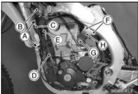
- Remove:
Engine Guard [A]
Middle Engine Bracket Bolts and Nuts [B]
Middle Engine Mounting Bolt and Nut [C]
Middle Engine Brackets (Left and Right) [D]
Lower Engine Mounting Bolts and Nuts [E]
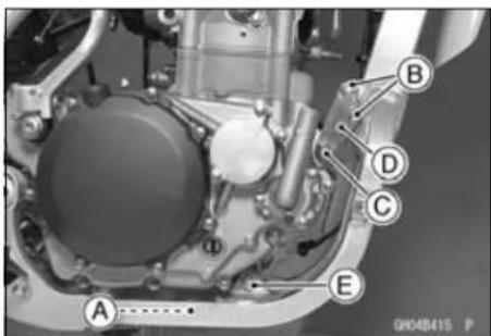
Engine Removal/Installation
- Remove the swingarm pivot shaft nut [A] to pull out the swingarm pivot shaft [B].
○Pull out the swingarm pivot shaft half way from right side to free the engine. - Remove the engine from the vehicle to right side.
- Clear the engine rear portion from the swingarm and then remove the engine.
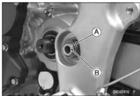
Engine Removal/Installation
Engine Installation
- Install the engine.
○First, insert the front portion of the engine, and then install the rear portion. - Install the swingarm pivot shaft, all engine bracket and mounting bolts temporarily.
○Swingarm pivot shaft insert from the right side.
○Insert the middle and lower engine mounting bolts from the left side. - Replace the swingarm pivot shaft nut and lower engine mounting nut with new ones.
- First tighten the pivot shaft nut, next tighten the lower engine mounting nut.
Torque - Swingarm Pivot Shaft Nut: 98 N·m (10 kgf·m, 72 ft·lb)
Lower Engine Mounting Nut (M10): 49 N·m (5.0 kgf·m, 36 ft·lb)
- Replace the middle engine mounting nut and bracket nuts with new ones.
- Tighten the following.
○Tighten the M10 bolts and nut first.
Torque - Upper Engine Mounting Bolts (M10): 49 N·m (5.0 kgf·m, 36 ft·lb)
Middle Engine Mounting Nut (M10): 49 N·m (5.0 kgf·m, 36 ft·lb)
Upper Engine Bracket Bolts (M8): 29 N·m (3.0 kgf·m, 21 ft·lb)
Middle Engine Bracket Nuts (M8): 29 N·m (3.0 kgf·m, 21 ft·lb)
○Install the shim to the inside of the right upper engine bracket (KLX450A8F Model).
- Install the removed parts (see Appropriate chapter).
- Run the cables, hoses, and leads according to the Cable, Wire, and Hose Routing section in the Appendix chapter.
- Fill: Engine Oil (see Engine Oil Change in the Periodic Maintenance chapter) Coolant (see Coolant Filling in the Cooling System chapter)
- Adjust: Throttle Cable (see Throttle Grip Free Play Adjustment in the Periodic Maintenance chapter) Clutch Cable (see Clutch Lever Free Play Adjustment in the Periodic Maintenance chapter) Drive Chain (see Drive Chain Slack Adjustment in the Periodic Maintenance chapter)
- Adjust the idling (see Idle Speed Adjustment in the Periodic Maintenance chapter).
- Check the operation of the clutch lever.
- Check the brake effectiveness.
Engine Removal/Installation
WARNING
After servicing, it takes several applications of the brake pedal before the brake pads contact the disc, which could result in increased stopping distance and cause an accident resulting in injury or death. Do not attempt to ride the motorcycle until a firm brake pedal is obtained by pumping the pedal until the pads are against the disc.
Crankshaft/Transmission
Table of Contents
Exploded View.... 9-2
Specifications 9-4
Special Tools and Sealant 9-5
Crankcase 9-6
Crankcase Disassembly 9-6
Crankcase Assembly 9-8
Crankshaft/Connecting Rod 9-15
Crankshaft Removal 9-15
Crankshaft Installation 9-15
Crankshaft Disassembly 9-15
Crankshaft Assembly 9-15
Crankshaft Inspection 9-16
Connecting Rod Bend.... 9-17
Connecting Rod Twist 9-18
Torque Limiter 9-19
Torque Limiter Removal/Installation.... 9-19
Torque Limiter Inspection.... 9-19
Transmission 9-20
Transmission Shaft Removal 9-20
Transmission Shaft Installation 9-20
Transmission Shaft Disassembly 9-20
Transmission Shaft Assembly 9-21
Shift Fork Bending 9-22
Shift Fork/Gear Groove Wear 9-23
Shift Fork Guide Pin/Shift Drum Groove Wear 9-23
Gear Damage 9-23
Balancer 9-24
Balancer Removal.... 9-24
Balancer Installation.... 9-24
Bearings/Oil Seals 9-25
Bearing Replacement 9-25
Bearing Inspection 9-25
Oil Seal Inspection.... 9-26
9-2 CRANKSHAFT/TRANSMISSION
Exploded View
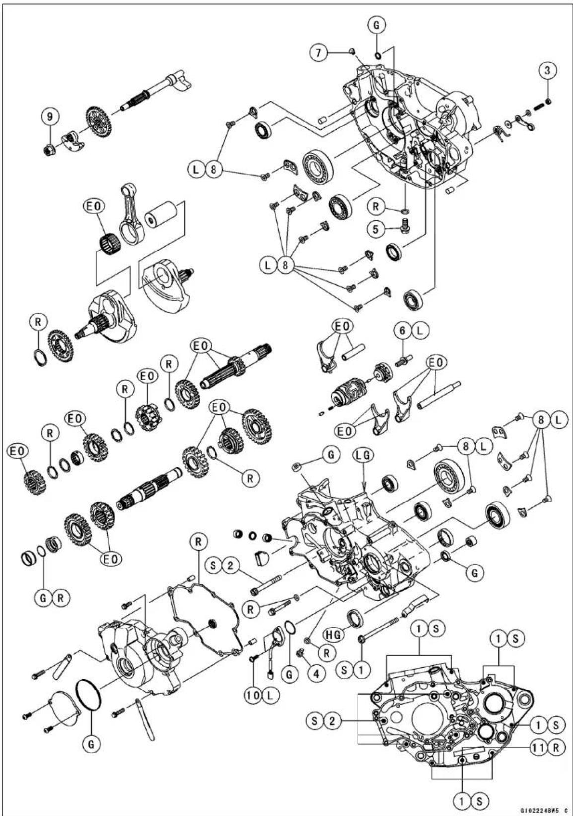
Exploded View
| No. | Fastener | Torque | Remarks | ||
| N·m | kgf·m | ft·lb | |||
| 1 | Crankcase Bolts (M6) | 12 | 1.2 | 106 in·lb | S |
| 2 | Crankcase Bolts (M7) | 15 | 1.5 | 11 | S |
| 3 | Gear Set Lever Nut 8.8 0.90 78 in·lb | ||||
| 4 | Engine Oil Drain Plug (M6)(Sub) | 7.0 | 0.71 | 62 in·lb | |
| 5 | Engine Oil Drain Plug (M10)(Main) | 20 | 2.0 | 15 | |
| 6 | Shift Drum Cam Bolt | 24 | 2.4 | 18 | L |
| 7 | Piston Oil Nozzle | 4.0 | 0.41 | 35 in·lb | |
| 8 | Bearing Retaining Screws | 15 | 1.5 | 11 | L |
| 9 | Balancer Weight Mounting Nut | 52 | 5.3 | 38 | |
| 10 | Gear Position Switch Screws | 2.9 | 0.30 | 26 in·lb | L |
- Copper Washer
EO: Apply engine oil.
G: Apply grease.
HG: Apply high-temperature grease.
L: Apply a non-permanent locking agent.
LG: Apply liquid gasket.
R: Replacement parts
S: Tighten the fasteners following the specified sequence.
9-4 CRANKSHAFT/TRANSMISSION
Specifications
| Item Standard Service Limit | ||
| Connecting Rods | ||
| Connecting Rod Big End Radial Clearance | 0.002 ~ 0.014 mm(0.00008 ~ 0.0006 in.) | 0.06 mm (0.002 in.) |
| Connecting Rod Big End Side Clearance | 0.25 ~ 0.35 mm(0.0098 ~ 0.014 in.) | 0.6 mm (0.02 in.) |
| Crankshaft Runout | TIR 0.03 mm (0.001 in.) or less | TIR 0.08 mm (0.003 in.) |
| Connecting Rod Bend | -- -- | TIR 0.2 mm (0.08 in.)/100 mm (3.94 in.) |
| Connecting Rod Twist | -- -- | TIR 0.2 mm (0.08 in.)/100 mm (3.94 in.) |
| Transmission | ||
| Shift Fork Ear Thickness | 4.9 ~ 5.0 mm (0.193 ~ 0.197 in.) | 4.8 mm (0.19 in.) |
| Gear Shift Fork Groove Width | 5.05 ~ 5.15 mm (0.199 ~ 0.203 in.) | 5.25 mm (0.207 in.) |
| Shift Fork Guide Pin Diameter | 5.9 ~ 6.0 mm (0.232 ~ 0.236 in.) | 5.8 mm (0.228 in.) |
| Shift Drum Groove Width | 6.05 ~ 6.20 mm (0.238 ~ 0.244 in.) | 6.3 mm (0.25 in.) |
TIR: Total Indicator Readings
Special Tools and Sealant
Outside Circlip Pliers: 57001-144
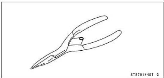
Bearing Driver Set: 57001-1129
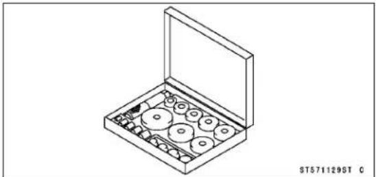
Crankshaft Jig: 57001-1174
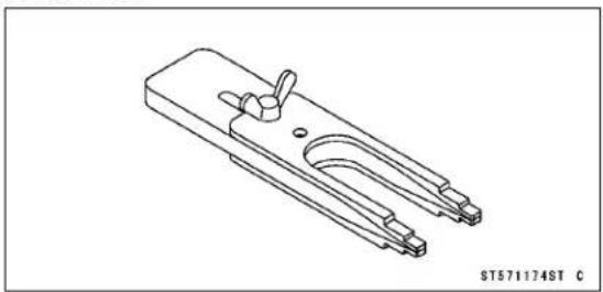
Crankcase Splitting Tool Assembly: 57001-1362
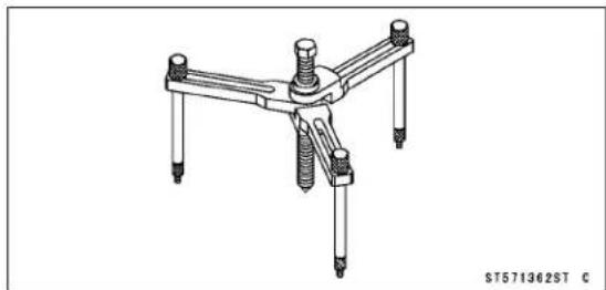
Liquid Gasket, TB1216: 92104-1063
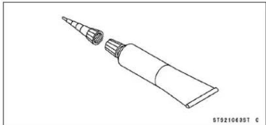
Crankcase
Crankcase Disassembly
- Remove the engine from the frame (see Engine Removal in the Engine Removal/Installation chapter).
- Set the engine on clean surface while parts are being removed.
- Remove:
Magneto Cover (see Magneto Cover Removal in the Electrical System chapter)
Cylinder Head Cover (see Cylinder Head Cover Removal in the Engine Top End chapter)
Cylinder Head (see Cylinder Head Removal in the Engine Top End chapter)
Cylinder (see Cylinder Removal in the Engine Top end chapter)
Piston (see Piston Removal in the Engine Top End chapter)
Right Engine Cover (see Right Engine Cover Removal in the Engine Right Side chapter)
Clutch (see Clutch Removal in the Engine Right Side chapter)
Primary Gear (see Primary Gear Removal in the Engine Right Side chapter)
Balancer (see Balancer Removal)
Oil Pumps (see Oil Pump (Scavenge)(Feed) Removal in the Engine Lubrication System chapter)
Kick Shaft Assembly (see Kick Shaft Removal in the Engine Right Side chapter)
Kick Shaft Idle Gear (see Idle Gear Removal in the Engine Right Side chapter)
External Shift Mechanism (see External Shift Mechanism Removal in the Engine Right Side chapter)
Flywheel (see Flywheel Removal in the Electrical System chapter)
- Remove the output shaft sleeve [A] and the O-ring [B].
○Do not reuse the O-ring.
- Remove:
Gear Position Switch Screws [A] Gear Position Switch [B]

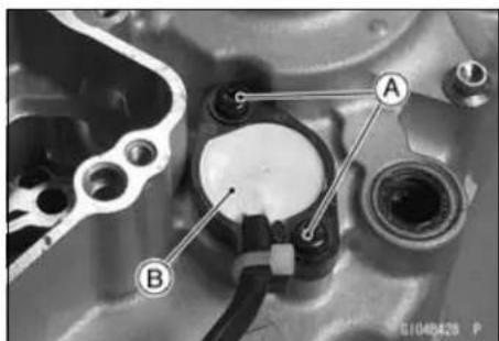
Crankcase
- Remove:
Gear Position Switch Finger [A]
Spring [B]
- Remove:
Circlip [A]
Balancer Drive Gear [B]
Special Tool - Outside Circlip Pliers: 57001-144
- Remove:
Circlip [A]
Special Tool - Outside Circlip Pliers: 57001-144
- Remove the crankcase bolts [A].
- Pry the points [A] with a screwdriver to split the crankcase halves apart evenly. There are two dowel pins on the crankcase mating surface. Pull off the left crankcase half.
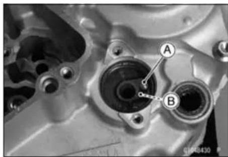
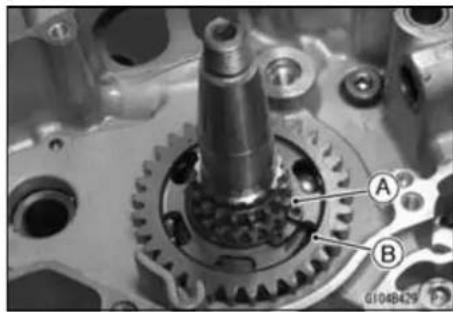
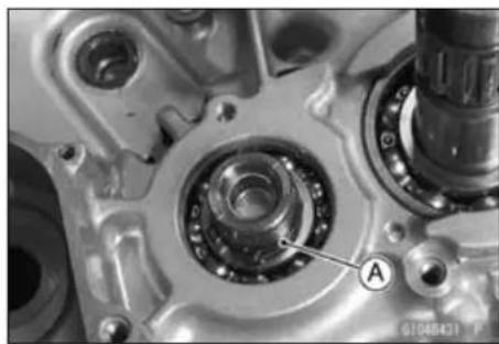
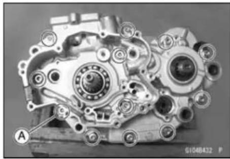
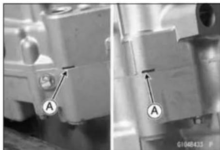
9-8 CRANKSHAFT/TRANSMISSION
Crankcase
- The crankcase may also be split, using the crankcase splitting tool assembly.
○Install the jig [A] between the crankshaft flywheels.
Special Tool - Crankshaft Jig: 57001-1174
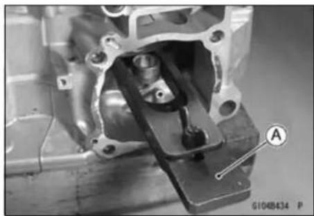
○Attach the crankcase splitting tool [A] to the left crankcase. Special Tool - Crankcase Splitting Tool Assembly: 57001 -1362
○ Tighten the center bolt [B] of the crankcase splitting tool to split the crankcase halves.
○Remove the left crankcase half.
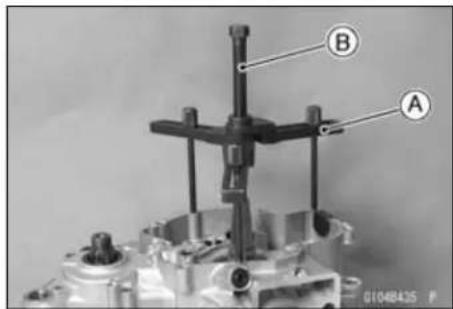
- Remove:
Oil Screen (Feed) [A] (see Oil S screen (Feed) Removal in the Engine Lubrication System chapter) Shift Rods [B] (see Transmission Shaft Removal) 2 Shift Forks [C] (see Transmission Shaft Removal) Shift Dram [D] (see Transmission Shaft Removal) Transmission [E] (see Transmission Shaft Removal) - Remove the crankshaft [F] from the right crankcase half (see Crankshaft Removal).

NOTICE
Do not remove the bearings and the oil seals unless it is necessary. Removal may damage them.
Crankcase Assembly
NOTICE
Right and left crankcase halves are machined at the factory in the assembled state, so if replaced, they must be replaced as a set.
- Remove the old gasket from the mating surfaces of the crankcase halves and clean them off with a high-flash point solvent.
- Using compressed air, blow out the oil passages in the crankcase halves.
WARNING
Gasoline and low-flash point solvents can be flammable and/or explosive and cause severe burns. Clean the engine parts in a well-ventilated area, and take care that there is no spark or flame anywhere near the working areas. Do not use gasoline or low-flash point solvents to clean parts.
Crankcase
- Support the crankcase bearing boss with a suitable retainer [A].
- Using a press and the bearing driver set [C], install a new bearing [B] until it bottoms out.
Special Tool - Bearing Driver Set: 57001-1129
NOTICE
Support the crankcase bearing boss when the bearing is pressed, or the crankcase could be damaged.
-
Press the new transmission shaft bearing [A] in the left crankcase half, so that the sealed side [B] faces outside of the engine.
Special Tool - Bearing Driver Set: 57001-1129 -
Press the new drive shaft bearing [A] in the right crankcase [B] half, so that the stepped side [C] faces inside of the engine.
Special Tool - Bearing Driver Set: 57001-1129 -
Press the new crankshaft bearings [A] in the left and right crankcase half [B], so that the stepped side [C] faces inside of the engine.
Special Tool - Bearing Driver Set: 57001-1129 -
Press the shift drum needle bearing [A] and shift shaft needle bearing [B] in the left crankcase half, so that bearing surface flush with the crankcase surface [C].
Special Tool - Bearing driver Set: 57001-1129
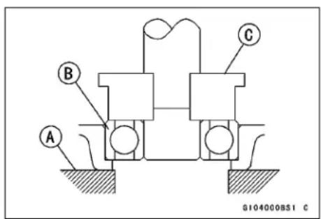
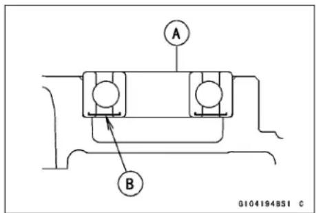
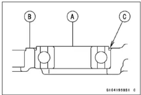
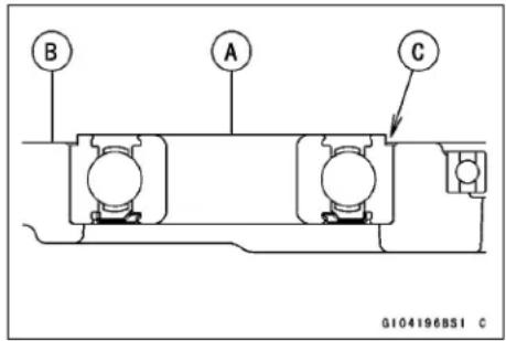
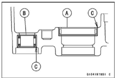
9-10 CRANKSHAFT/TRANSMISSION
Crankcase
- First, press the inside release shaft needle bearing [A] until its top comes 19.5 mm [B] from the surface using the bearing driver set.
- Next, press the oil seal [C] until it reach to the inside needle bearing with the bearing driver set.
Special Tool - Bearing driver Set: 57001-1129

- Next, press the outside release shaft needle bearing [A] until the surface of the bearing is even with the crankcase surface [B].
Special Tool - Bearing driver Set: 57001-1129
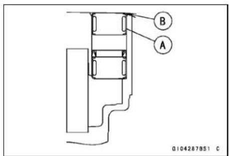
- Replace the oil seals, if removed.
- Press the oil seals [A] of the output shaft, shift shaft, and pull rod so that oil seal lip [B] face to the engine outside and oil seal surface flush with the left crankcase surface [C].
- Apply high-temperature grease to the oil seal lip. Special Tool - Bearing driver Set: 57001-1129
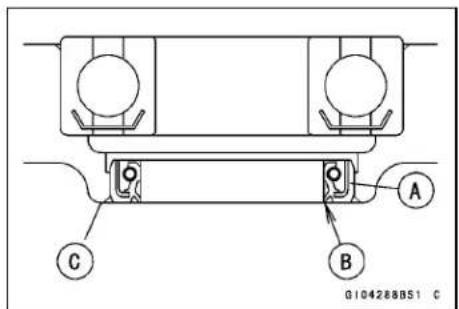
- Apply a non-permanent locking agent to the retaining screws.
- Tighten the bearing retaining screws [A]. Torque - Bearing Retaining Screws: 15 N·m (1.5 kgf·m, 11 ft·lb) Piston Oil Nozzle [B]: 4.0 N·m (0.41 kgf·m, 35 in·lb)
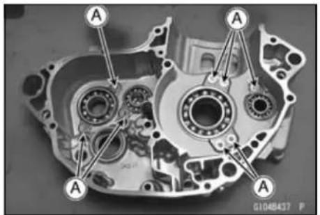
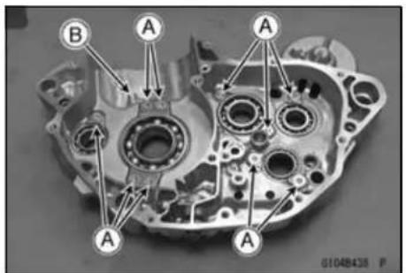
Crankcase
- Apply engine oil to the transmission gears, bearings, shift forks, shift drum and crankshaft bearing.
- Install the drive shaft [A] and output shaft [B] in the right crankcase [C] as a set.
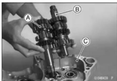
- Install: Shift Drum [A] (see Transmission Shaft Installation) Shift Rods [B] (see Transmission Shaft Installation) Shift Forks [C] (see Transmission Shaft Installation)
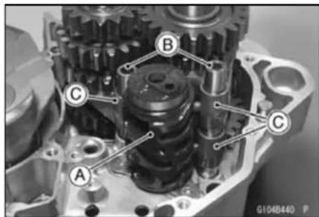
• Install: Crankshaft [A] Dowel Pins [B]
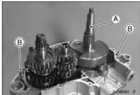
- Replace the O-ring [A] with a new one. - Install the Oil Screen (Feed). Torque - Oil Screen (Feed) Mounting Bolts: 9.8 N·m (1.0 kgf·m, 87 in·lb)
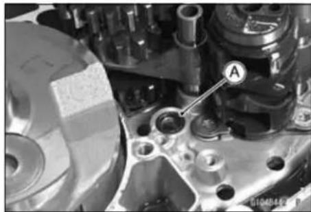
- With the connecting rod positioned at the bottom-dead-center, install the crankshaft jig [A]. Special Tool - Crankshaft Jig: 57001-1174
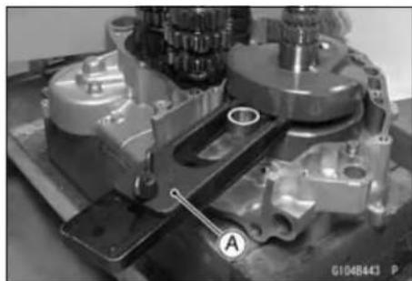
9-12 CRANKSHAFT/TRANSMISSION
Crankcase
- Apply liquid gasket to the mating surface [A] of the left crankshaft half.
Sealant - Liquid Gasket, TB1216: 92104-1063
NOTE
○ Make the application finish within 30 minutes when the liquid gasket to the mating surface of the left crankcase half is applied.
- Moreover fit the case and tighten the case bolts just after finishing the application of the liquid gasket.
- Using a plastic mallet [A], press [B] the rear portion of the crankcase, and tap the area around the crankshaft of the left crankcase. While maintaining the mating surfaces of the right and left crankcase halves constantly parallel, mate the crankcase halves evenly.
NOTE
○ Constantly check the alignment of the two crankcase halves, and the position of the transmission shafts, and shift drum. The front and rear of the crankcase must be pushed together evenly.
- Remove the crankshaft jig [C].
- Tighten the crankcase bolts, starting with the periphery of the crankshaft, then outward.
- Replace the copper washer [B] with a new one.
○Tighten the crankcase bolt together with the clamp [A].
Torque - CrankcaseBolts (M6): 12 N·m (1.2 kgf·m, 106 in·lb) Crankcase Bolts (M7): 15 N·m (1.5 kgf·m, 11 ft·lb)
NOTE
○After tightening the crankcase bolts, wipe up the liquid gasket seeping out around the mating surface, especially around the area.
- Make sure that the crankshaft, driveshaft, and the output shaft, rotate smoothly (in the neutral position).
★If the crankshaft will not turn, probably the crankshaft is not centered; tap the appropriate end of the crankshaft with a mallet [A] to reposition it.
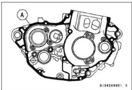
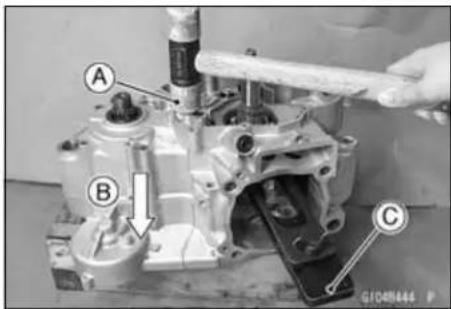
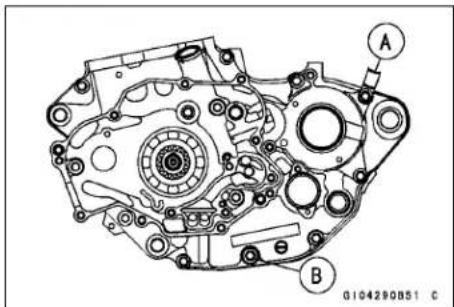
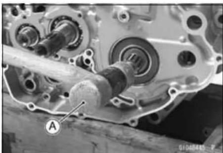
Crankcase
- Install the gear set lever [A].
○Fit each end [B] of the spring or original positions.
○Do not forget to install the collar and washer [C]. - Tighten the gear set lever nut [D].
Torque - Gear Set Lever Nut: 8.8 N·m (0.90 kgf·m, 78 in·lb)
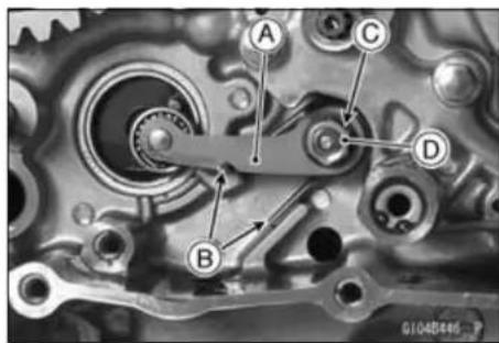
- To install the shift drum cam [A], use the driver [B] to bring the gear set lever [C] to the bottom of the crankcase.
- Mate the shift drum pin [D] into the shift drum hole.
○Fit the groove [E] of the shift drum cam on the shift drum pin. - Apply non-permanent locking agent to the shift drum cam bolt and tighten it.
Torque - Shift Drum Cam Bolt: 24 N·m (2.4 kgf·m, 18 ft·lb)
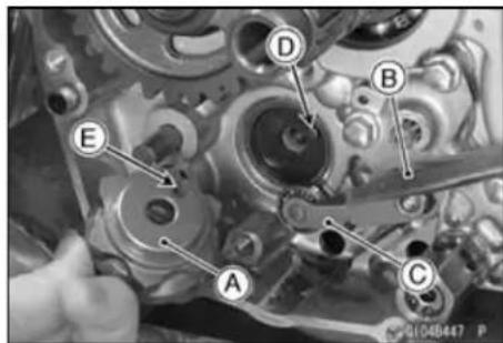
- Check to see that gears shift smoothly from 1st to 5th gear, and 5th to 1st while spinning the output shaft.
- Set the shift drum in the neutral position.
- Replace the O-ring [A] on the output shaft with new one and apply grease it.
- Install the O-ring on the grinding faces of the output shaft while expanding the O-ring by the hand.
- Apply grease to the inside of the output shaft collar [B].
- Insert the collar with the oil groove ends [C] facing in.
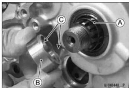
- Install the balancer drive gear [A] so that the stepped portion [B] of the balancer drive gear and crankshaft are aligned.
- Replace the circlip with a new one, and install it.
Special Tool - Outside Circlip Pliers: 57001-144
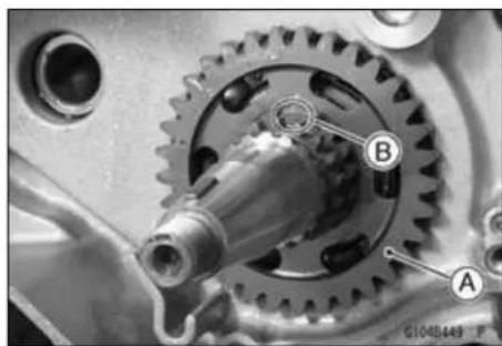
9-14 CRANKSHAFT/TRANSMISSION
Crankcase
- Replace the circlip [A] with a new one, and install it to the output shaft.
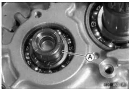
Crankshaft/Connecting Rod
Crankshaft Removal
- Disassemble the crankcase (see Crankcase Disassembly).
- Using the hand pull out the crankshaft [A] from the right crankcase [B].
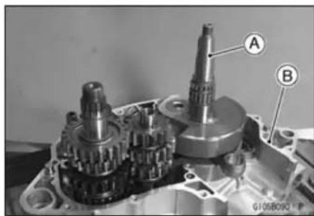
Crankshaft Installation
- Apply high-temperature grease to the outer side of the crankshaft bearings and use the bearing driver set [C] to face the steppedside[A] to the engine inside and drivethe bearing to the bottom of the crankcase [B]. While driving the bearing in, make sure to use a holder to support the boss area.
Special Tool - Bearing Driver Set: 57001-1129
• Install the crankshaft to the right crankcase.
- Apply engine oil to the connecting rod big end bearing.
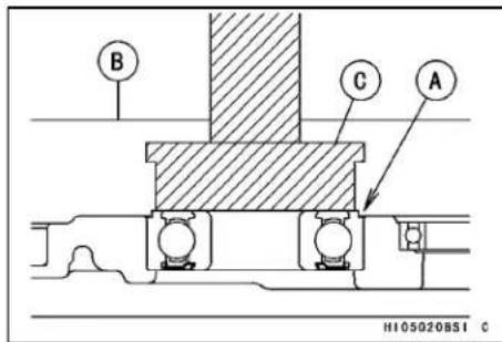
Crankshaft Disassembly
Since assembly of the crankshaft demands exacting tolerances, the disassembly and reassembly of the crankshaft can only be done by a shop having the necessary tools and equipment.
★If it should be necessary to disassemble the crankshaft, use a press to remove the crankpin.
Crankshaft Assembly
Since the assembly of the crankshaft demands exacting tolerances, the disassembly and reassembly of the crankshaft can only be done by a shop having the necessary tools and equipment.
- Carefully align the oil passage hole in the right flywheel [A] with the one in the crankpin [B] at rebuilding of the crankshaft as shown.
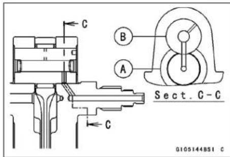
- Reassemble the crankshaft according to the standard tolerances in Specifications.
○Connecting rod bend, twist.
○Connecting rod big end radial clearance.
○Cold-fitting tolerance between crankpin and flywheels.
○Side clearance between the connecting rod big end and one of flywheels.
○Crankshaft runout.
Crankshaft/Connecting Rod
Crankshaft Inspection
Connecting Rod Big End Radial Clearance
- Set the crankshaft on V blocks, and place a dial gauge [A] against the connecting rod big end.
- Push [B] the connecting rod first towards the gauge and then in the opposite direction. The difference between two gauge readings is the radial clearance.
Connecting Rod Big End Radial Clearance
Standard: 0.002 mm \~ 0.014 mm (0.00008 \~ 0.0006 in.)
Service Limit: 0.06 mm (0.002 in.)
★If the radial clearance exceeds the service limit, crankshaft should be either replaced or disassembled and crankpin, needle bearing, and connecting rod big end should be examined for wear.
Connecting Rod Big End Side Clearance
- Measure the connecting rod big end side clearance [A].
Connecting Rod Big End Side Clearance
Standard: 0.25 \~ 0.35 mm (0.0098 \~ 0.014 in.)
Service Limit: 0.6 mm (0.02 in.)
★If the clearance exceeds the service limit, replace the crankshaft assembly.
Crankshaft Runout
- Set the crankshaft in a flywheel alignment jig or on V blocks, and place a dial gauge as shown and turn the crankshaft slowly. The maximum difference in gauge reading is the crankshaft runout.
Crankshaft Runout
Standard: TIR 0.03 mm (0.001 in.) or less
Service Limit: TIR 0.08 mm (0.003 in.)
★If the runout at either point exceeds the service limit, replace the crankshaft assembly with a new one or align the crankshaft so that the runout falls within the service limit. 8.5 mm (0.33 in.) [A]
- First correct the horizontal misalignment by striking the projecting crank half [A] with a plastic, soft lead, or brass hammer as shown.
- Recheck the runout with a dial gauge and repeat the process until the runout falls within the service limit.
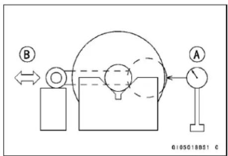
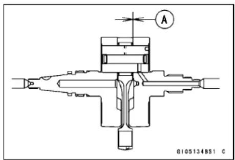
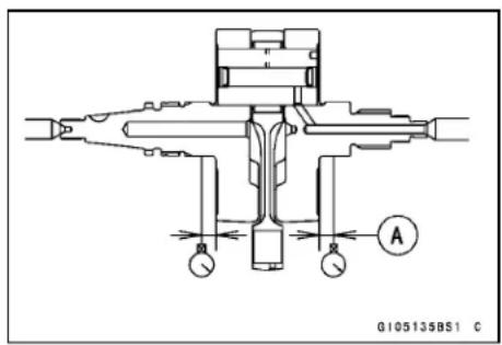
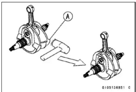
Crankshaft/Connecting Rod
- Next, correct the vertical misalignment by either driving a wedge [A] in between the crank halves or by squeezing them in a vice, depending on the nature of the misalignment.
NOTICE
Do not hammer the crank half at the point [B].
★If flywheel misalignment cannot be corrected by the above method, replace the crank pin or the crankshaft itself.
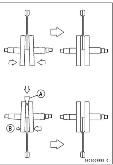
Connecting Rod Big End Seizure
★In case of serious seizure with damaged flywheels, the crankshaft must be replaced.
★In case of less serious damage, disassemble the crankshaft and replace the crankpin, needle bearing, and connecting rod.
Connecting Rod Bend
- Remove the connecting rod.
- Select an arbor [A] of the same diameter as the connecting rod big end, and insert the arbor through the connecting rod big end.
- Select an arbor of the same diameter as the piston pin and more than 105 mm long, and insert the arbor [B] through the connecting rod small end.
- On a surface plate, set the big-end arbor on a V block [C].
- With the connecting rod held vertically, use a height gauge to measure the difference in the height of the arbor above the surface plate over a 100 mm length to determine the amount of connecting rod bend.
★If connecting rod bend exceeds the service limit, the connecting rod must be replaced.
Connecting Rod Bend
Service Limit: TIR 0.2/100 mm (0.08/3.94 in.)
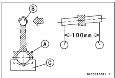
9-18 CRANKSHAFT/TRANSMISSION
Crankshaft/Connecting Rod
Connecting Rod Twist
- With the big-end arbor [A] still on the V block [C], hold the connecting rod horizontally and measure the amount that the arbor [B] varies from being parallel with the surface plate over a 100 mm length of the arbor to determine the amount of connecting rod twist.
★If connecting rod twist exceeds the service limit, the connecting rod must be replaced.
Connecting Rod Twist
Service Limit: TIR 0.2/100 mm (0.08/3.94 in.)
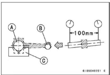
Torque Limiter
Torque Limiter Removal/Installation
- Remove:
Torque Limiter Cover Bolts [A]
Torque Limiter Cover [B]
Torque Limiter [C]
NOTICE
Do not disassemble the torque limiter. The torque limiter will not function if this is done.
- Install the torque limiter cover so that the arrow mark [A] faces upward.
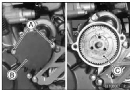
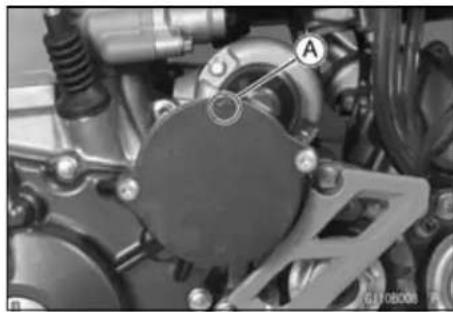
Torque Limiter Inspection
- Remove the torque limiter and visually inspect it.
★If the limiter has wear, discoloration, or other damage, replace it as a set.
Gear [A]
Shaft [B]
Spring [C]
Pinion [D]
Shim [E]
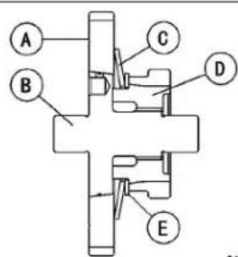
G110003BSI C
Transmission
Transmission Shaft Removal
- Disassemble the crankcase halves (see Crankcase Disassembly).
- Pull out the shift rods [A] allowing the shift fork guide pins to free from the shift drum [B].
- Remove the shift forks [C].
- Remove the shift drum.
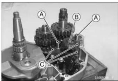
- Pull out the drive shaft [A] and output shaft [B] together with their gears meshed.
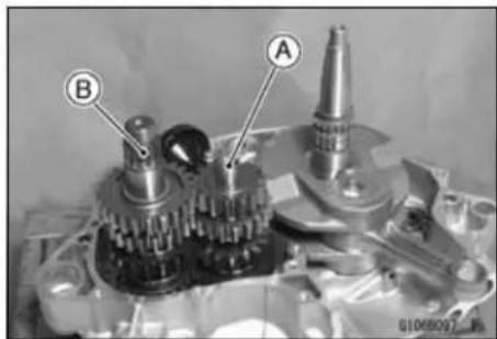
Transmission Shaft Installation
- Apply engine oil to the sliding portion of the transmission shafts, gears, and ball bearings.
- Install the drive shaft [A] and output shaft [B] in the right crankcase [C] with their gears meshed.
• Install the shift drum.
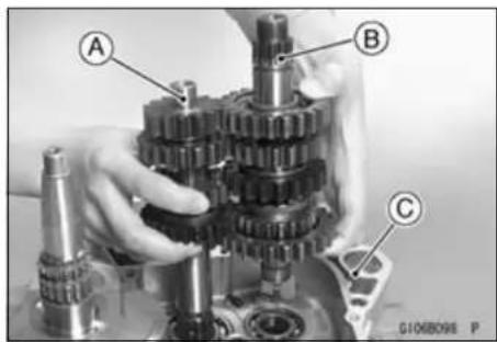
- Apply a small amount of engine oil to the shift fork fingers and fit each shift fork into the groove of the proper gear.
- The shift forks can be identified by their shape or mark. Install them noting the direction shown.
○Install each shift forks with its mark [A] facing the engine left side.
Marks:
43 (Drive shaft)
47 (Output shaft)
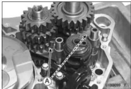
- Assembly the crankcase (see Crankcase Assembly).
○Fit each shift fork guide pin into the corresponding groove in the shift drum.
○Apply a small amount of engine oil to the shift rods and slide them into the shift forks.
○Assembly the crankcase (see Crankcase Assembly).
Transmission Shaft Disassembly
- Remove the transmission shafts.
- Remove the circlips, washers, then gears.
Special Tool - Outside Circlip Pliers: 57001-144 - Do not reuse the removed circlips.
Transmission
Transmission Shaft Assembly
- Apply engine oil liberally to the transmission shaft, gears and bearings.
- Replace any circlips that were removed with new ones.
○Always install the circlips [A] so that the opening [B] is aligned with a spline groove [C], and install toothed washers. To install a circlip without damage, first fit the circlip onto the shaft expanding it just enough to install it, and then use a suitable gear to push the circlip into place.
Special Tool - Outside Circlip Pliers: 57001-144
- The drive shaft gears can be identified by size; the smallest diameter gear is 1st gear, and the largest is 5th. Be sure that all parts are put back in the correct sequence, facing the proper direction, and that all circlips and the washers are properly in place.
- The output shaft gears can be identified by size; the largest diameter gear is 1st gear, and the smallest is 5th. Be sure that all parts are put back in the correct sequence, facing the proper direction, and that all circlips and washers are properly in place.
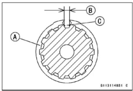
Transmission
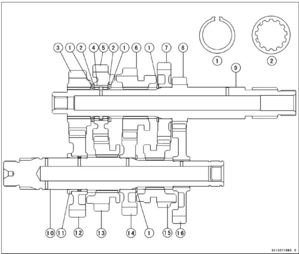
-
Circlip
-
5th Gear (21 T)
-
4th Gear (19 T)
-
Toothed Washer
-
1st Gear (12 T)
-
3rd Gear (19 T)
-
2nd Gear (15 T)
-
Drive Shaft
-
5th Gear (17 T)
-
Bushing
-
Output Shaft
-
1st Gear (26 T)
-
4th Gear (20 T)
-
Collar
-
3rd Gear (16 T)
-
2nd Gear (23 T)
- Check each gear spins or slides freely on the transmission shaft without binding after assembly.
Shift Fork Bending
- Visually inspect the shift forks, and replace any fork that is bent. A bent fork may cause difficulty in shifting, or allow the transmission to jump out of gear when under power. 90° [A]
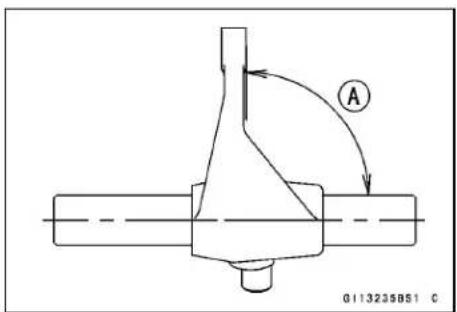
Transmission
Shift Fork/Gear Groove Wear
- Measure the thickness [A] of the shift fork ears, and measure the width [B] of the gear grooves (with which the fork engages).
Shift Fork Ear Thickness
Standard: 4.9 \~ 5.0 mm (0.193 \~ 0.197 in.)
Service Limit: 4.8 mm (0.19 in.)
Gear Groove Width
Standard: 5.05 \~ 5.15 mm (0.199 \~ 0.203 in.)
Service Limit: 5.25 mm (0.207 in.)
★If the thickness of a shift fork ear is less than the service limit, the shift fork must be replaced.
★If the gear groove is worn exceeding the service limit, the gear must be replaced.
Shift Fork Guide Pin/Shift Drum Groove Wear
- Measure the diameter of each shift fork guide pin [A], and measure the width [B] of each shift drum groove.
Shift Fork Guide Pin Diameter
Standard: 5.9 \~ 6.0 mm (0.232 \~ 0.236 in.)
Service Limit: 5.8 mm (0.228 in.)
Shift Drum Groove Width
Standard: 6.05 \~ 6.20 mm (0.238 \~ 0.244 in.)
Service Limit: 6.3 mm (0.25 in.)
★If the guide pin on any shift fork is less than the service limit, the fork must be replaced.
★If any shift drum groove is worn exceeding the service limit, the drum must be replaced.
Gear Damage
- Visually inspect the gear dogs [A] and gear dog holes [B].
★Replace any damaged gears or gears with excessively worn dogs or dog holes. - Visually inspect the gear teeth [C] on the transmission gears.
★Replace lightly damaged gear teeth with an oilstone. The gear must be replaced if the teeth are badly damaged.
★When gearis repaired or replaced, the driving gear should also be inspected and repaired or replaced if necessary.
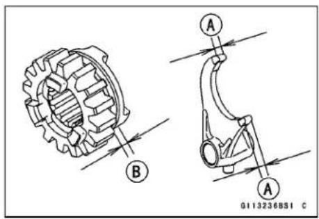
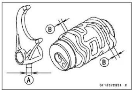
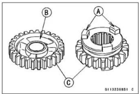
9-24 CRANKSHAFT/TRANSMISSION
Balancer
Balancer Removal
- Remove:
Right Engine Cover (see Right Engine Cover Removal in the Engine Right Side chapter) Magneto Cover (see Magneto Cover Removal in the Electrical System chapter)
Flywheel (see Flywheel Removal in the Electrical System chapter)
- Install the flywheel [A] temporary and hold it steady with the flywheel holder [B], loosen the balancer weight mounting nut [C].
Special Tool - Flywheel Holder: 57001-1313
- Remove:
Balancer Weight Mounting Nut Balancer Weight [D] Balancer Gear [E]
- Pull out the balancer shaft from the right crankcase.
Balancer Installation
- Insert the balancer shaft from the right crankcase.
- Install the balancer gear so that the stepped portion [A] on the balancer shaft and punch mark [B] on the balancer gear align.
- Align the punch mark [A] on the balancer drive gear and punch mark [B] on the balancer gear.
- Install the balancer weight so that the punch mark [A] on the balancer and punch mark [B] on the balancer gear.
- Install the flywheel temporary and hold it steady with the flywheel holder, tighten the balancer weight mounting nut.
Torque - Balancer Weight Mounting Nut: 52 N·m (5.3 kgf·m, 38 ft·lb)
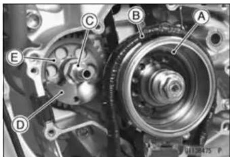
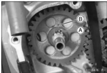
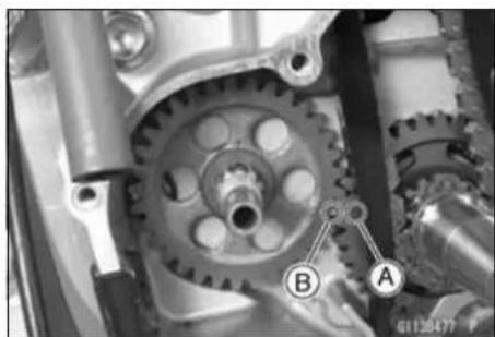
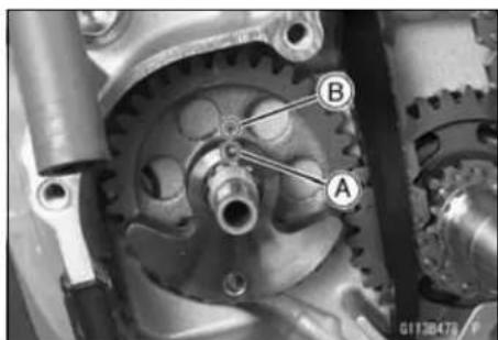
Bearings/Oil Seals
Bearing Replacement
NOTICE
Do not remove the ball bearings unless it is necessary. Removal may damaged them.
- Remove the ball bearing and/or needle bearing outer race using a press or puller.
NOTE
○ In the absence of the above mentioned tools, satisfactory results may be obtained by heating the case to approximately 93°C (200°F) max, and tapping the bearing in or out.
NOTICE
Do not heat the case with a torch. This will warp the case. Soak the case in oil and heat the oil.
- Install the new bearing until its outer race stops at the bottom of the case using a press and the bearing driver set [A].
Special Tool - Bearing Driver Set: 57001-1129
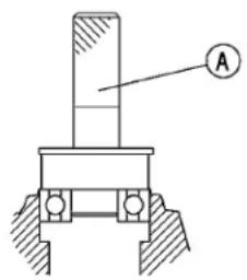
G1140605S1 C
Bearing Inspection
NOTICE
Do not remove the bearings for inspection. Removal may damage them.
- Inspect the ball bearings.
○Since the ball bearings are made to extremely close tolerances, the wear must be judged by feel rather than measurement. Clean each bearing in a high-flash point solvent, dry it (do not spin the bearing while it is dry), and oil it with engine oil to it.
○Spin [A] the bearing by hand to check its condition.
★If the bearing is noisy, does not spin smoothly, or has any rough spots, replace it.
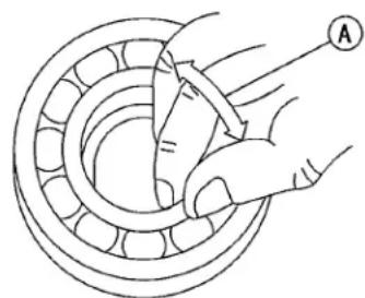
G1130149S1 C
9-26 CRANKSHAFT/TRANSMISSION
Bearings/Oil Seals
- Check the needle bearing.
- The rollers in a needle bearing normally wear very little, and wear is difficult to measure. Instead of measuring, inspect the bearing for abrasion, color change, or other damage.
★If there is any doubt as to the condition of a needle bearing, replace it.
Oil Seal Inspection
- Inspect the oil seal.
★Replace the oil seal if the lips are deformed, discolored (indicating that the rubber has deteriorated), hardened or otherwise damaged.
Wheels/Tires
Table of Contents
Exploded View 10-2
Specifications 10-4
Special Tools 10-5
Wheels (Rims) 10-6
Front Wheel Removal 10-6
Front Wheel Installation 10-6
Rear Wheel Removal 10-8
Rear Wheel Installation 10-9
Wheels Inspection.... 10-10
Spoke Tightness Inspection.... 10-10
Rim Runout Inspection.... 10-10
Axle Inspection.... 10-10
Tires 10-11
Tire Removal.... 10-11
Tire Installation.... 10-12
Air Pressure Inspection/Adjustment 10-13
Hub Bearings.... 10-14
Hub Bearing Removal.... 10-14
Hub Bearing Installation.... 10-14
Hub Bearing Inspection.... 10-14
Hub Bearing Lubrication 10-15
Exploded View
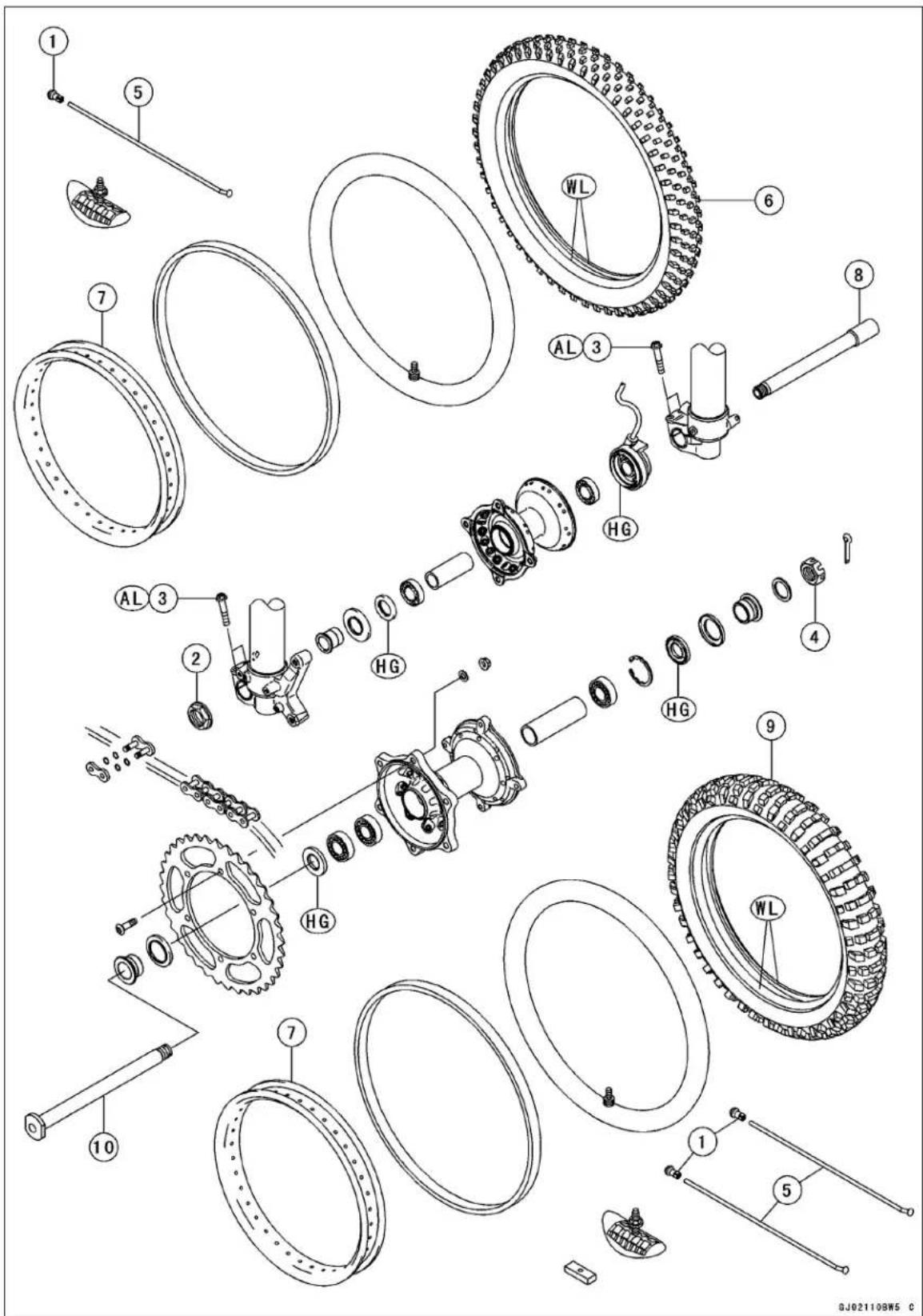
Exploded View
| No. | Fastener | Torque | Remarks | ||
| N·m kgf·m ft·lb | |||||
| 1 | Spoke Nipples 2.2 0.22 19 in·lb | ||||
| 2 | Front Axle Nut 79 8.0 58 | ||||
| 3 | Front Axle Clamp Bolts | 20 | 2.0 | 15 | AL |
| 4 | Rear Axle Nut | 110 | 11.2 | 81.1 | |
- Spokes
- Front Tire
- Rims
- Front Axle
- Rear Tire
- Rear Axle
AL: Tighten the two clamp bolts alternately two times to ensure even tightening torque.
HG: Apply high temperature grease.
WL: Apply soap and water solution, or rubber lubricant.
Specifications
| Item Standard Service Limit | ||
| Wheels (Rims) | ||
| Rim Runout: | ||
| Axial | TIR 1.0 mm (0.039 in.) or less | TIR 2 mm (0.08 in.) |
| Radial | TIR 1.0 mm (0.039 in.) or less | TIR 2 mm (0.08 in.) |
| Axle Runout/100 mm (3.94 in.) | 0.1 mm (0.004 in.) or less | 0.2 mm (0.008 in.) |
| Rim Size: | ||
| Front 21 × 1.60 - - - | ||
| Rear 18 × 2.15 - - - | ||
| Tires Air Pressure | ||
| Front and Rear | 100 kPa (1.0 kgf/cm2, 14 psi) | - - - |
| Tires | ||
| Standard Tire: | ||
| Front: | ||
| Size | 80/100-21 51M(AU) (EUR) 80/100-21 M/C 51P | - - - |
| Make | BRIDGESTONE | - - - |
| Type | M401, Tube(AU) (EUR) ED03, Tube | - - - |
| Rear: | ||
| Size | 110/100-18 64M(AU) (EUR)120/90-18 M/C 65P | - - - |
| Make | BRIDGESTONE | - - - |
| Type | M402, Tube(AU) (EUR) ED04, Tube | - - - |
Special Tools
Inside Circlip Pliers: 57001-143
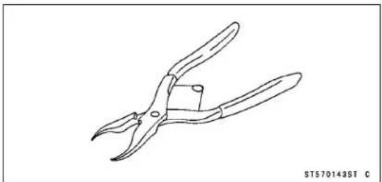
Rim Protector: 57001-1063
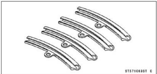
Bead Breaker Assembly: 57001-1072
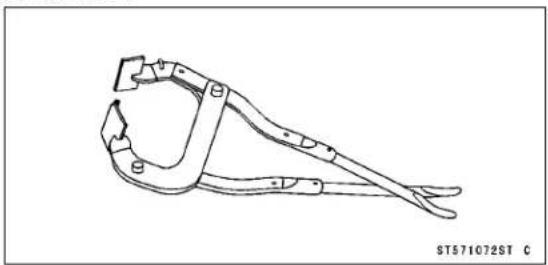
Bearing Driver Set: 57001-1129
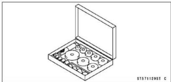
Jack: 57001-1238
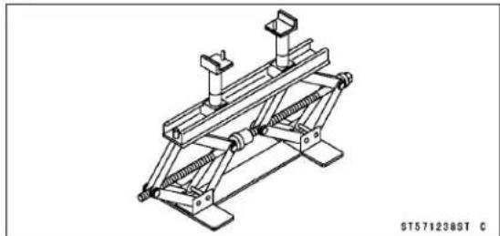
10-6 WHEELS/TIRES
Wheels (Rims)
Front Wheel Removal
- Using the jack [A] under the frame, and stabilize the motorcycle.
Special Tool - Jack: 57001-1238 - Apply the rear brake to rear wheel does not turn.
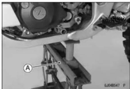
- Unscrew the axle nut [A].
- Loosen the left and right axle clamp bolts [B].
- Place a commercially available jack under the engine to raise the front wheel off the ground.
- Remove the axle [C], and pull out the wheel. Take off the collars and caps [D] from each side of the front hub.
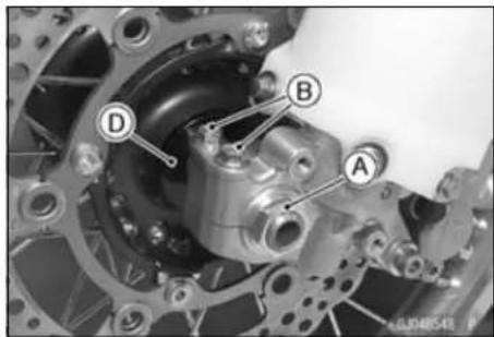
NOTICE
Do not lay the wheel on the ground with the disc facing down. This can damage or warp the disc. Place blocks under the wheel so the disc does not touch the ground.
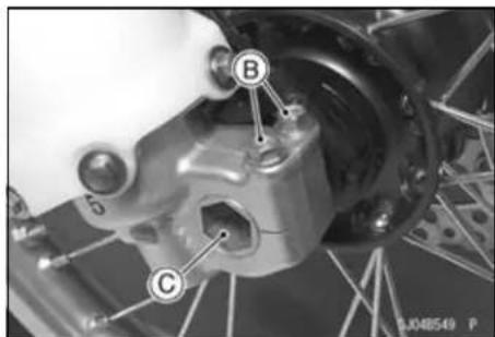
- Insert a wood wedge between the disc brake pads this prevents them from being moved out of their proper position, should the brake lever be squeezed accidentally.
Front Wheel Installation
- Apply grease to the seals.
- Fit the projection [A] on the cap to the groove [B] on the collar.
- Install the caps and collars on the left and right side of the hub.
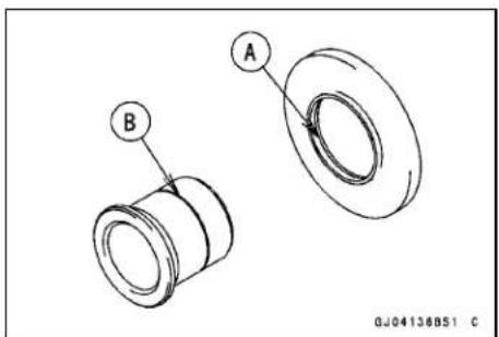
Wheels (Rims)
- Install the speedometer gear housing so that the projections [A] fit in the drive notches [B].
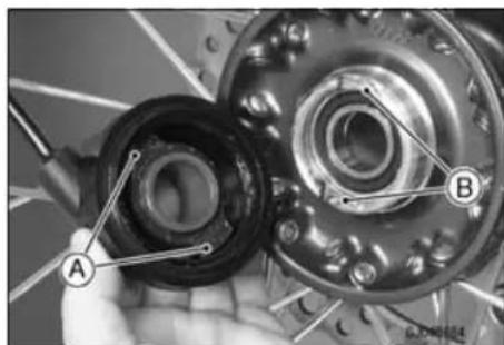
● Fit the collar on the right side of the hub.
- Fit the speedometer gear housing stop [A] on the fork leg clamp flat face [B].
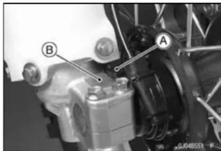
- Insert the axle [A] from right side.
● Tighten the right [B] axle clamp bolts temporally. - Tighten the axle nuts [C].
- Tighten the left axle clamp bolts [D].
Torque - Front Axle: 79 N·m (8.0 kgf·m, 58 ft·lb) Left Axle Clamp Bolts: 20 N·m (2.0 kgf·m, 15 ft·lb)
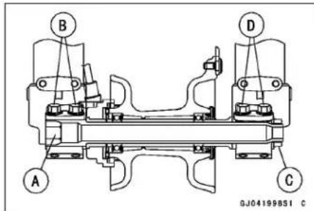
NOTE
○ Tighten the two clamp bolts alternately two times to ensure even tightening torque.
10-8 WHEELS/TIRES
Wheels (Rims)
- Remove the jack.
- Before tightening the right clamp bolts on the right fork leg, pump the forks up and down [A] 4 or 5 times to allow the right fork leg to find a neutral position on the front axle.
NOTE
○Do not apply the front brake during this process to stop the motorcycle from rolling forward. Put a block [B] in front of the wheel to stop it from moving.
- Tighten the right axle clamp bolts.
Torque - Right Axle Clamp Bolts: 20 N·m (2.0 kgf·m, 15 ft·lb)
NOTE
○ Tighten the two clamp bolts alternately two times to ensure even tightening torque.
- Check the front brake for good braking power and no brake drag.
WARNING
After servicing, it takes several applications of the brake lever before the brake pads contact the disc, which could result in increased stopping distance and cause an accident resulting in injury or death. Do not attempt to ride the motorcycle until a firm brake lever is obtained by pumping the lever until the pads are against the disc.
Rear Wheel Removal
- Using the jack under the frame so that the rear wheel is raised off the ground.
Special Tool - Jack: 57001-1238
- Remove
Cotter Pin [A] Axle Nut [B]
- Pull out the axle [C], and remove the chain adjuster.
- Disengage the drive chain from the rear sprocket toward the left.
- Move the rear wheel back with the rear caliper installed.
● Take off the collar and cap from the each side of the rear hub.
NOTICE
Do not lay the wheel on the ground with the disc facing down. This can damage or warp the disc. Place blocks under the wheel so the disc does not touch the ground.
- Insert a wood wedge between the brake pads. This prevents them from being moved out of their proper position, should the brake pedal be squeezed accidentally.
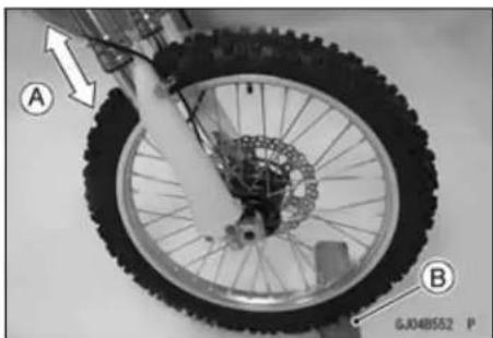
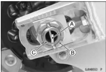
Wheels (Rims)
Rear Wheel Installation
- Install the groove [A] of the brake holder [B] onto the projection [C] of the swingarm.
- Install the rear wheel while holding the disc cover [D].
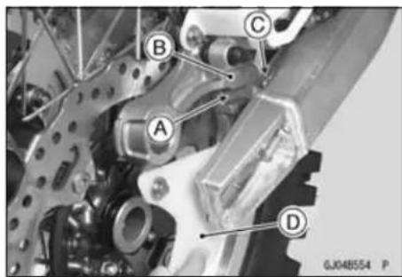
- Fit the projection on the cap to the groove on the collar.
- Install the collars [A] on the left and right side of the hub. ○The collars are identical.
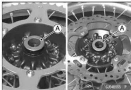
- Engage the drive chain with the rear sprocket, and install the rear wheel.
- Insert the axle from the left side of the wheel, and install the axle nut.
- Check the drive chain slack (see Drive Chain Slack Inspection in the Periodic Maintenance chapter).
- Tighten the axle nut.
Torque - Rear Axle Nut: 110 N·m (11.2 kg·m, 81.1 ft·lb) - Install the new cotter pin [A] and spread its end.
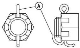
SK04001BS1 C
NOTE
○ When inserting the cotter pin, if the slots in the nut do not align with the cotter pin hole in the axle shaft, tighten the nut clockwise [A] up to next alignment.
○ It should be within 30 degree.
○ Loosen one and tighten again when the slot goes past the nearest hole.
WARNING
A loose axle nut can lead to an accident resulting in serious injury or death. Tighten the axle nut to the proper torque and install a new cotter pin.
- Install the disc cover.
- Check the rear brake for good braking power and no brake drag.

GJ04034BS1 C
WARNING
After servicing, it takes several applications of the brake pedal before the brake pads contact the disc, which could result in increased stopping distance and cause an accident resulting in injury or death. Do not attempt to ride the motorcycle until a firm brake pedal is obtained by pumping the pedal until the pads are against the disc.
Wheels (Rims)
Wheels Inspection
- Place the jack under the frame so that the front/rear wheel is raised off the ground.
Special Tool - Jack: 57001-1238 - Spin the wheellightly, and check for roughness or binding.
★If the roughness or binding is found, replace the hub bearings. - Visually inspect the front and rear axles for damage.
★If the axle is damaged or bent, replace it.
Spoke Tightness Inspection
- Refer to the Spoke Tightness Inspection in the Periodic Maintenance chapter.
Rim Runout Inspection
- Refer to the Rim Runout Inspection in the Periodic Maintenance chapter.
Axle Inspection
- Visually inspect the front and rear axle for damages.
★If the axle is damaged or bent, replace it. - Place the axle in V blocks that are 100 mm (3.937 in.) [A] apart, and set a dial gauge on the axle at a point halfway between the blocks. Turn the axle to measure the runout. The difference between the highest and lowest dial readings is the amount of runout.
★If the runout exceeds the service limit, replace the axle.
Axle Runout/100 mm (3.94 in.)
Standard: 0.1 mm (0.004 in.) or less
Service Limit: 0.2 mm (0.008 in.)
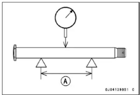
Tires
Tire Removal
NOTICE
Do not lay the wheel on the ground with the disc facing down. This can damage or warp the disc. Place blocks under the wheel so the disc does not touch the ground.
- Remove the wheel from the motorcycle (see Wheels Removal).
- To maintain front wheel balance, mark [A] the valve stem position on the tire with chalk so that the tire can be reinstalled in the same position.
- Remove the valve cap [B].
- Take out the valve core [A] to let out the air.
- Remove the valve stem nut [B].
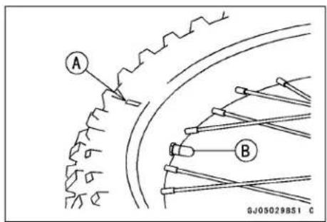
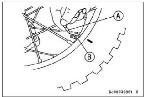
- Loosen the bead protector nut [A].
- Lubricate the tire beads and rim flanges on both sides with a soap and water solution or rubber lubricant. This helps the tire beads slip off the rim flanges.
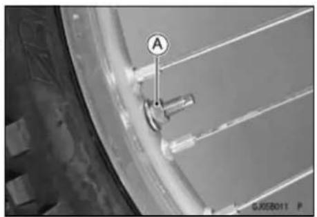
NOTICE
Never lubricate with mineral oil (engine oil) or gasoline because they will cause deterioration of the tire.
- Break the beads away from both sides of the rim with the bead breaker [A].
Special Tool - Bead Breaker Assembly: 57001-1072
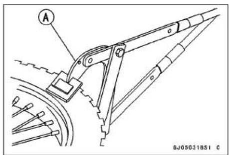
Tires
- Step on the side of the tire opposite valve stem, pry the tire off the rim with the tire iron [A] of the bead breaker protecting the rim with rim protectors [B].
Special Tools - Rim Protector: 57001-1063
Bead Breaker Assembly: 57001-1072
NOTICE
Take care not to inset the tire irons so deeply that the tube gets damaged.
- Remove the bead protector and tube when one side of the tire is pried off.
- Pry the tire off the rim.
Tire Installation
NOTE
○ The Tires should be installed so that the ID serial NO. [A] faces to left side.
- Inspect the rim and tire, and replace them if necessary.
• Install the tube band and tube. - Apply a soap and water solution, or rubber lubricant to the rim flange and tire beads.
- Position the front tire on the rim so that the valve [A] is at the tire balance mark [B] (the chalk mark made during removal, or the white paint mark on a new tire. see Removal).
- Insert the valve stem into the rim, and screw the nut on loosely.
- Fit the rim protectors and use tire irons to install the tire bead.
NOTE
To prevent rim damage, be sure to place the rim protectors at any place the tire irons are applied.
- Pry one side of the tire back onto the rim. Fit the bead protector into the tire.
- Pry the other side of the tire onto the rim, starting at the side opposite the valve.
- Take care not to insert the tire irons so deeply that the tube is damaged.
- Install the other side of the tire bead onto the rim in the same manner.
- Check that the tube is not pinched between the tire and rim.
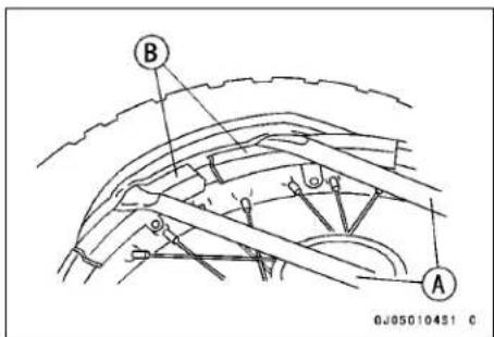
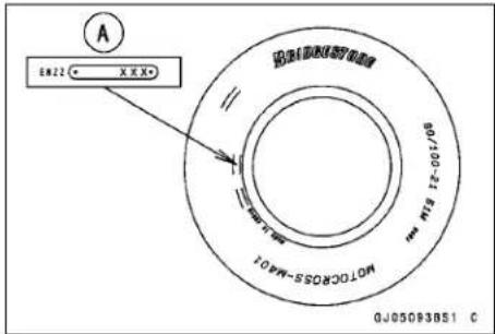
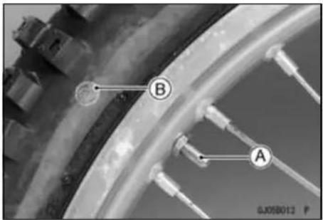
Tires
- Tighten the bead protector nut [A] and valve stem nut [B], and put on the valve cap [C].
- Check and adjust the air pressure after installing.
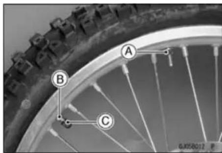
Air Pressure Inspection/Adjustment
- Refer to the Air Pressure Inspection/Adjustment in the Periodic Maintenance chapter.
Hub Bearings
Hub Bearing Removal
- Remove the wheel (see Wheel Removal).
NOTICE
Do not lay the wheel on the ground with the disc facing down. This can damage or warp the disc. Place blocks under the wheel so that the disc does not touch the ground.
- Remove the oil seals and circlips.
Special Tool - Inside Circlip Pliers: 57001-143
- Remove the hub bearing by tapping evenly around the bearing inner race as shown.
[A] Bar
[B] Distance Collar
[C] Hub Bearing
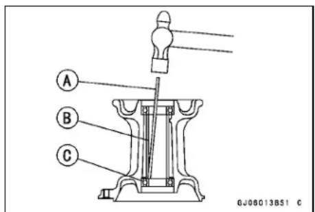
Hub Bearing Installation
- Before installing the wheel bearings, blow any dirt or foreign particles out of the hub [A] with compressed air to prevent contamination of the bearings.
- Replace the bearings with new ones.
- Lubricate them and install them using the bearing driver set [B] so that the marked or shielded sides face out.
○Press in the bearings until they are bottomed.
Special Tool - Bearing Driver Set: 57001-1129
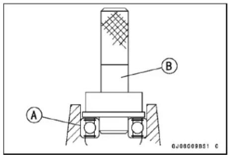
- Replace the circlips and oil seals with new ones.
- Press in the oil seals [A] so that the seal surface is flush [B] with the end of the hole.
- Apply high temperature grease to the oil seal lips.
Special Tool - Bearing Driver set: 57001-1129 [C]
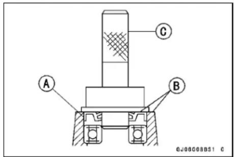
Hub Bearing Inspection
NOTE
- It is not necessary to remove any bearings for inspection. If any bearings are removed, they will need to be replaced with new ones.
- Spin [A] it by hand to check its condition.
★If it is noisy, does not spin smoothly, or has any rough spots, it must be replaced. - Examine the bearing seal [B] for tears or leakage.
★If the seal is torn or is leaking, replace the bearing.
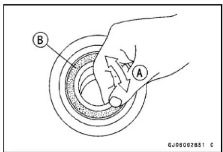
Hub Bearings
Hub Bearing Lubrication
NOTE
○ Since the hub bearings are packed with grease and sealed, lubrication is not required.
Final Drive
Table of Contents
Exploded View.... 11-2
Specifications 11-4
Drive Chain.... 11-5
Drive Chain Slack Inspection 11-5
Drive Chain Slack Adjustment 11-5
Wheel Alignment Inspection 11-5
Wheel Alignment Adjustment.... 11-5
Drive Chain Wear Inspection 11-5
Drive Chain Lubrication.... 11-5
Drive Chain Removal 11-5
Sprockets.... 11-9
Engine Sprocket Removal 11-9
Engine Sprocket Installation 11-9
Rear Sprocket Removal.... 11-9
Rear Sprocket Installation.... 11-10
Sprocket Wear Inspection.... 11-10
Rear Sprocket Warp Inspection 11-10
11-2 FINAL DRIVE
Exploded View
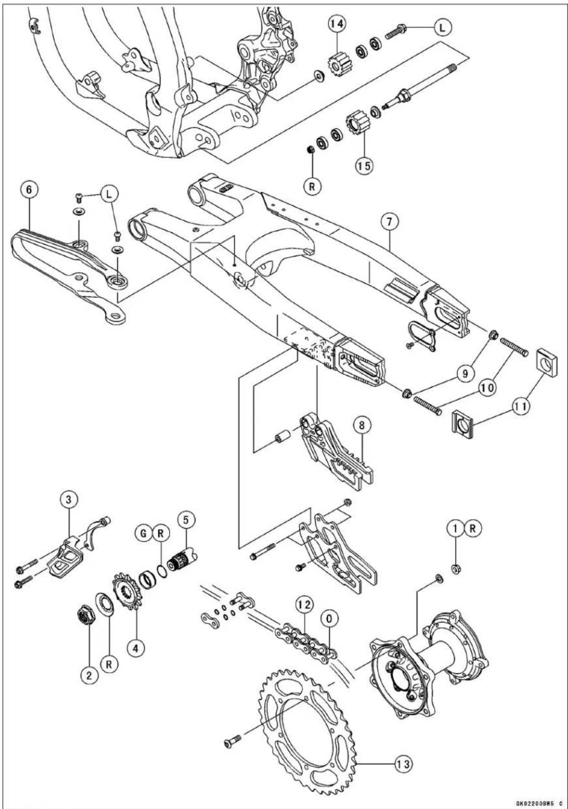
Exploded View
| No F | Fastener | Torque | Remarks | ||
| N·m kgf | m ft·lb | ||||
| 1 | Rear Sprocket Nuts | 34 | 3.5 | 25 | R |
| 2 Engine Sprocket Nut 127 13.0 93.7 | |||||
- Engine Sprocket Cover
- Engine Sprocket
- Output Shaft
- Chain Slipper
- Swingarm
- Chain Guide
- Locknut
- Adjusting Bolt
- Chain Adjuster
- Drive Chain
- Rear Sprocket
- Upper Chain Guide Roller
- Lower Chain Guide Roller
G: Apply grease.
L: Apply a non-permanent locking agent.
O: Apply oil.
R: Replacement Parts
11-4 FINAL DRIVE
Specifications
| Item Standard Service Limit | ||
| Drive Chain | ||
| Chain Slack | 52 ~ 58 mm (2.0 ~ 2.3 in.) | - - - |
| Chain 20-link Length | 317.5 ~ 318.2 mm (12.50 ~ 12.53 in.) | 323 mm (12.7 in.) |
| Standard Chain: | ||
| Make | DAIDO | - - - |
| Type D.I.D. 520MXV - - - | ||
| Length 114 Links | - - - | |
| Link Pin Outside Diameter | 5.5 ~ 5.8 mm (0.22 ~ 0.23 in.) | - - - |
| Link Plate Outside Width | 16.50 ~ 16.70 mm (0.650 ~ 0.657 in.) | - - - |
| Sprocket | ||
| Rear Sprocket Warp | 0.4 mm (0.016 in.) or less | 0.5 mm (0.020 in.) |
Drive Chain
Drive Chain Slack Inspection
- Refer to the Drive Chain Slack Inspection in the Periodic Maintenance chapter.
Drive Chain Slack Adjustment
- Refer to the Drive Chain Slack Adjustment in the Periodic Maintenance chapter.
Wheel Alignment Inspection
- Check that the rear end [A] of the left chain adjuster aligns with the same swing arm mark [B] as the right chain adjuster.
WARNING
Misalignment of the wheel will result in abnormal wear and may result in an unsafe riding condition. Be sure the wheel is properly aligned.
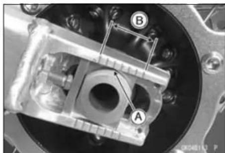
Wheel Alignment Adjustment
This procedure is the same as Drive Chain Slack Adjustment (see Drive Chain Slack Adjustment in the Periodic Maintenance chapter).
Drive Chain Wear Inspection
- Refer to the Drive Chain Wear Inspection in the Periodic Maintenance chapter.
Drive Chain Lubrication
- Refer to the Drive Chain Lubrication in the Periodic Maintenance chapter.
Drive Chain Removal
- Using a suitable tool, replace the drive chain.
Recommended Tool - DID Chain Joint "ZJ" MakeDAIDO KOGYO
NOTICE
Read the Tool Instruction Manual before replacing the chain.
- Remove:
Body [A]
Pin Holder [B]
Positioning Pin [C]
"U" Holder [D]
Plate Holder [E]
Cutting and Riveting Pin [F]
Part for Riveting [G]
Part for Cutting [H]
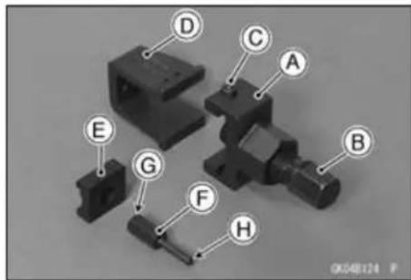
11-6 FINAL DRIVE
Drive Chain
- Grind [A] the heads of the link pin to make it flat.
- Set the cutting and riveting pin [C] in the pin holder [B] as shown in the figure.
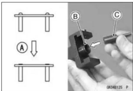
- Set the "U" holder and body, align the positioning pin [A] with the "A mark" [B].
- Turn the pin holder [C] clockwise until the cutting and riveting pin touches the link pin.
- Be sure that the cutting and riveting pin hits center of the link pin.

- Hold the body with a wrench [A].
- Turn the pin holder clockwise [B] with another wrench and remove the link pin.
- Do the same procedure for removal of the other link pin.
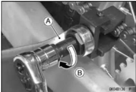
Drive Chain Installation
- Engage the new drive chain to the old drive chain and change the position of the chains by pulling the old chain.
- Remove the old drive chain from the new drive chain.
- Replace the link pin [A], link plate and grease seals [B] [C] with new ones.
- Apply grease to the link pin and grease seals.
- Install the grease seals on the link pin and insert it in the ends of the drive chain.
- Install the link plate so that the mark [D] faces out.
- Set the cutting and riveting pin [B] and plate holder [C] on the pin holder [A] as shown in the figure.
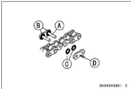
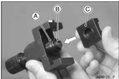
Drive Chain
- Set the "U" holder and body, align the positioning pin [A] with the "A mark" [B].
- Hold the body with a wrench [C].
- Turn the pin holder clockwise [D] with another wrench and press in the link plate on the link pin.
- Remove the "U" holder and body.
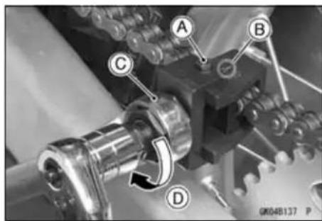
- Set the cutting and riveting pin [B] in the pin holder [A] as shown in the figure.
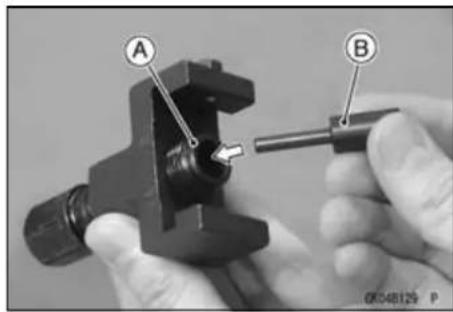
- Set the "U" holder and body, align the positioning pin [A] with the "B mark" [B].
- Turn the pin holder [C] clockwise until the cutting and riveting pin touches the link pin.
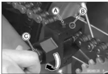
- Hold the body with a wrench [A] and turn the pin holder clockwise [B] with another wrench until the cutting and riveting pin touches the link plate.
- Do the same procedure for removal of the other link pin.
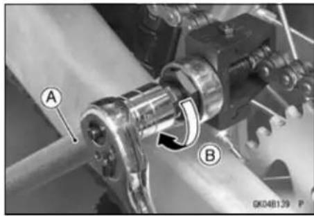
Drive Chain
- After riveting, check the ends of the riveted pins for cracks.
- Measure the outside diameter [A] of the link pin and width [B] of the link plates.
Link Pin Outside Diameter
Standard: 5.5 \~ 5.8 mm (0.22 \~ 0.23 in.)
Link Plate Outside Width
Standard: 16.50 \~ 16.70 mm (0.650 \~ 0.657 in.)
★If the reading is not the specified length, cut and rejoin the chain again.
- Check that the rollers move smoothly.
- Adjust the drive chain slack after installing the chain (see Drive Chain Slack Adjustment in the Periodic Maintenance chapter).
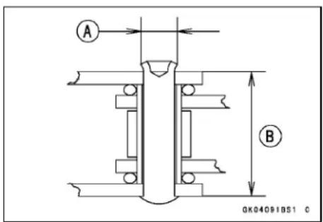
Sprockets
Engine Sprocket Removal
- Remove:
Engine Sprocket Cover Bolts [A]
Engine Sprocket Cover [B]
Drive Chain Guide [C]
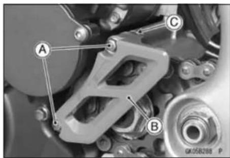
- Remove:
Drive Chain [B] (free of engine sprocket)
- Flatten the bended sprocket washer [A].
- Remove the engine sprocket nut [C] and sprocket washer, and pull off the engine sprocket [D].
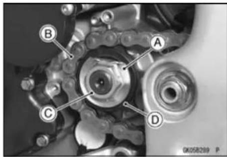
Engine Sprocket Installation
- Install the engine sprocket so that the flatten side faces [A] inside.
- Replace the sprocket washer with a new one.
• Install the sprocket washer and sprocket nut.
Torque - Engine Sprocket Nut: 127 N·m (13.0 kgf·m, 93.7 ft·lb)
- Bend the one side of the sprocket washer on the nut.
• Install the engine sprocket cover.
Torque - Engine Sprocket Cover Bolts : 9.8 N·m (1.0 kgf·m, 87 ft·lb)
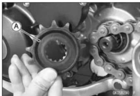
Rear Sprocket Removal
- Remove the rear wheel (see Rear wheel Removal in the Wheels/Tires chapter).
NOTICE
Do not lay the wheel on the ground with the disc facing down. This can damage or warp the disc. Place blocks under the wheel so that the disc does not touch the ground.
- Unscrew the rear sprocket bolts [A], and remove the rear sprocket [B].
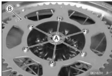
11-10 FINAL DRIVE
Sprockets
Rear Sprocket Installation
- Install the rear sprocket [A] so that the marked side [B] faces out.
- Replace the rear sproket nuts with new ones.
● Install the rear sprocket bolts and tighten the nuts.
Torque - Rear Sprocket Nuts: 34 N·m (3.5 kgf·m, 25 ft·lb)
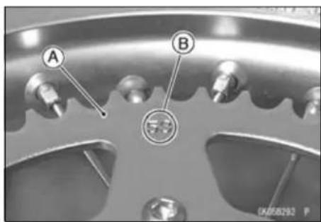
Sprocket Wear Inspection
- Refer to the Sprocket Wear Inspection in the Periodic Maintenance chapter.
Rear Sprocket Warp Inspection
- Refer to the Rear Sprocket Warp Inspection in Periodic Maintenance chapter.
Brakes
Table of Contents
Exploded View 12-2
Specifications 12-6
Special Tools 12-7
Brake Lever, Brake Pedal 12-8
Brake Lever Adjustment.... 12-8
Brake Pedal Position Adjustment.... 12-8
Brake Pedal Removal 12-8
Brake Pedal Installation 12-8
Brake Fluid 12-9
Fluid Level Inspection 12-9
Fluid Change.... 12-9
Bleeding the Brake Line.... 12-10
Caliper 12-12
Caliper Removal 12-12
Caliper Installation 12-12
Caliper Disassembly 12-13
Fluid Seal Damage 12-13
Dust Seal and Cover Damage 12-13
Piston Cylinder Damage 12-13
Caliper Holder Shaft Wear 12-13
Brake Pad Removal 12-14
Brake Pad Installation 12-14
Brake Pad Inspection.... 12-14
Master Cylinder 12-15
Front Master Cylinder Removal 12-15
Front Master Cylinder Installation 12-15
Rear Master Cylinder Removal.... 12-16
Rear Master Cylinder Installation.... 12-16
Front Master Cylinder Disassembly 12-16
Rear Master Cylinder Disassembly.... 12-16
Master Cylinder Assembly 12-16
Master Cylinder Inspection (Visual Inspection) 12-17
Brake Disk 12-18
Brake Disc Removal 12-18
Brake Disc Installation 12-18
Brake Disc Inspection 12-18
Brake Hose.... 12-19
Brake Hose Removal/Installation 12-19
Brake Hose Inspection.... 12-19
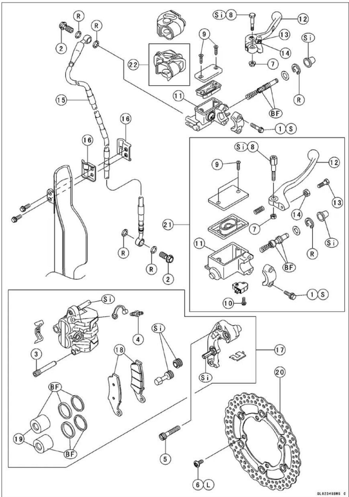
Exploded View
| No. | Fastener | Torque | Remarks | ||
| N·m kgf·m ft·lb | |||||
| 1 | Front Master Cylinder Clamp Bolts | 8.8 | 0.90 | 78 in·lb | S |
| 2 | Brake Hose Banjo Bolts | 25 | 2.5 | 18 | |
| 3 | Brake Pad Bolt | 17 | 1.7 | 13 | |
| 4 | Caliper Bleed Valve | 7.8 0.80 | 69 in·lb | ||
| 5 | Caliper Mounting Bolts | 25 | 2.5 | 18 | |
| 6 | Front Brake Disc Mounting Bolts | 10 | 1.0 | 89 in·lb | L |
| 7 | Brake Lever Pivot Bolt Locknut | 5.9 | 0.60 | 52 in·lb | |
| 8 | Brake Lever Pivot Bolt | 5.9 | 0.60 | 52 in·lb | Si |
| 9 | Brake Reservoir Cap Screws | 1.5 0.15 | 13 in·lb | ||
| 10 | Front Brake Light Switch Screw | 1.2 0.12 | 10 in·lb | ||
- Front Brake Reservoir
- Brake Lever
- Brake Lever Adjuster
- Locknut
- Brake Hose
- Clamps
- Front Caliper
- Brake Pad
- Piston
- Front Disc
- Australia Models
- KLX450A9F Model \~
BF: Apply brake fluid.
L: Apply a non-permanent locking agent.
R: Replacement Parts
S: Tighten the fasteners following the specified sequence.
Si: Apply silicone grease.
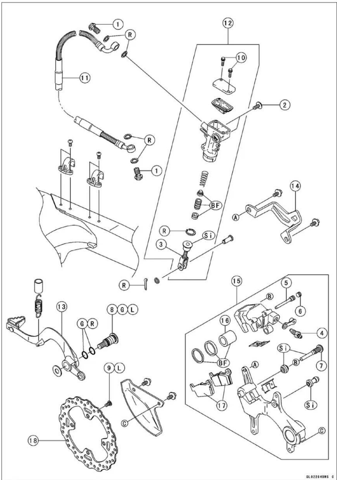
Exploded View
| No. | Fastener | Torque | Remarks | ||
| N·m kgf | m ft·lb | ||||
| 1 | Brake Hose Banjo Bolts | 25 | 2.5 | 18 | |
| 2 | Rear Master Cylinder Mounting Bolts | 10 | 1.0 | 89 in·lb | |
| 3 | Rear Master Cylinder Push Rod Locknut | 17 | 1.7 | 13 | |
| 4 | Caliper Bleed Valve | 7.8 | 0.80 | 69 in·lb | |
| 5 | Brake Pad Bolt | 17 1.7 13 | |||
| 6 | Rear Brake Pad Bolt Plug | 2.4 | 0.24 | 21 in·lb | |
| 7 | Caliper Holder Shaft | 27 2.8 20 | Si | ||
| 8 | Brake Pedal Mounting Bolt | 25 | 2.5 | 18 | G,L |
| 9 | Rear Brake Disc Mounting Bolts | 23 | 2.3 | 17 | L |
| 10 | Brake Reservoir Cap Bolts | 1.5 | 0.15 | 13 in·lb | |
- Brake Hose
- Rear Master Cylinder
- Brake Pedal
- Rear Caliper Cover
- Rear Caliper
- Piston
- Brake Pads
- Rear Disc
BF: Apply brake fluid.
G: Apply high temperature grease.
L: Apply a non-permanent locking agent.
R: Replacement Parts
Si: Apply Silicone grease.
Specifications
| Item Standard Service Limit | ||
| Brake adjustmentLever Play Adjustable (to suit rider) | -- -- | |
| Brake FluidRecommended Disc Brake Fluid:TypeFrontRear DOT4 | DOT3 or DOT4 | -- -- |
| -- -- | ||
| Brake PadsLining thickness:Front 3.8 mm (0.15 in.) 1 mm (0.04 in.)Rear 6.4 mm (0.25 in.) 1 mm (0.04 in.) | ||
| Brake DiscThickness:FrontRearRunout | 2.85 ~ 3.15 mm (0.112 ~ 0.124 in.)3.85 ~ 4.15 mm (0.152 ~ 0.163 in.)TIR 0.25 mm (0.0098 in.) or less | 2.5 mm (0.10 in.)3.5 mm (0.14 in.)TIR 0.3 mm (0.01 in.) |
Special Tools
Inside Circlip Pliers: 57001-143
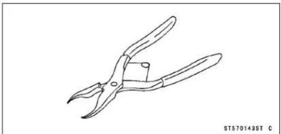
Jack: 57001-1238
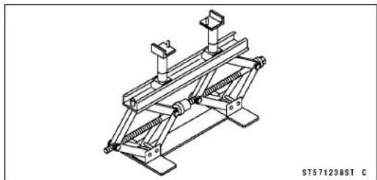
12-8 BRAKES
Brake Lever, Brake Pedal
Brake Lever Adjustment
- Refer to the Brake Lever and Pedal Position Adjustment in the Periodic Maintenance chapter.
Brake Pedal Position Adjustment
- Refer to the Brake Lever and Pedal Position Adjustment in the Periodic Maintenance chapter.
Brake Pedal Removal
- Remove: Cotter Pin [A] Joint Pin [B] Washer [C]
- Remove the mounting bolt [D] and take off the brake pedal [E] and return spring.
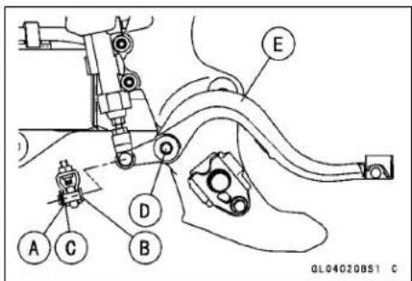
Brake Pedal Installation
- Replace O-rings with new one and apply high temperature grease to the O-rings.
- Apply high temperature grease to the shaft portion and a non-premanent locking agent to the thread of the brake pedal mounting bolt, and install the pedal with return spring onto the frame.
○Install the return spring direction [A] as shown.
Torque - Brake Pedal Mounting Bolt: 25 N·m (2.5 kgf·m, 18 ft·lb)
- Check the brake pedal position.
• Install the joint pin, washer and a new cotter pin.
○Bend the ends [A] of the cotter pin.
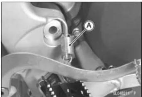
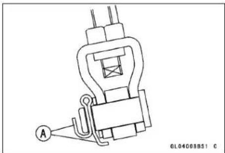
Brake Fluid
WARNING
When working with the disc brake, observe the precautions listed below.
- Never reuse old brake fluid.
- Do not use fluid from a container that has been left unsealed or that has been open for a long time.
- Do not mix two types and brands of fluid for use in the brake. This lowers the brake fluid boiling point and could cause the brake to be ineffective. It may also cause the rubber brake parts to deteriorate.
- Don't leave the reservoir cap off for any length of time to avoid moisture contamination of the fluid.
- Don't change the fluid in the rain or when a strong wind is blowing.
- Except for the disc pads and disc, use only disc brake fluid, isopropyl alcohol, or ethyl alcohol for cleaning of the brake parts. Do not use any other fluid for cleaning these parts. Gasoline, engine oil, or any other petroleum distillate will cause deterioration of the rubber parts. Oil spilled on any part will be difficult to wash off completely and will eventually deteriorate the rubber used in the disc brake.
- When handling the disc pads or disc, be careful that no disc brake fluid or any oil gets on them. Clean off any fluid or oil that inadvertently gets on the pads or disc with a high-flash point solvent. Do not use one which will leave an oily residue. Replace the pads with new ones if they cannot be cleaned satisfactorily.
- Brake fluid quickly ruins painted surfaces; any spilled fluid should be completely wiped up immediately.
- If any of the brake line fittings or the bleed valve is opened at any time, the AIR MUST BE BLED FROM THE BRAKE LINE.
Fluid Level Inspection
- Refer to the Brake Fluid Level Inspection in the Periodic Maintenance chapter.
Fluid Change
- Refer to the Brake Fluid Change in the Periodic Maintenance chapter.
Bleeding the Brake Line
The brake fluid has a very low compression coefficient so that almost all the movement of the brake lever or pedal is transmitted directly to the caliper for braking action. Air, however, is easily compressed. When air enters the brake lines, brake lever or pedal movement will be partially used in compressing the air. This will make the lever or pedal feel spongy, and there will be a loss in braking power.
WARNING
Air in the brake lines diminish braking performance and can cause an accident resulting in injury or death. If the brake lever or pedal has a soft or "spongy" feeling mushy when it is applied, there might be air in the brake lines or the brake may be defective. Do not operate the vehicle and service the brake system immediately.
NOTE
○ The procedure to bleed the front brake line is as follows. Bleeding the rear brake line is the same as for the front brake.
- Remove the reservoir cap, and check that there is plenty of fluid in the reservoir.
- With the reservoir cap off, slowly pump the brake lever several times until no air bubbles can be seen rising up through the fluid from the holes at the bottom of the reservoir.
- Bleed the air completely from the master cylinder by this operation.
- Install the reservoir cap.
- Attach a clear plastic hose to the bleed valve on the caliper, and run the other end of the hose into a container.
- Bleed the brake line and the caliper as follows:
○ Repeat this operation until no more air can be seen coming out into the plastic hose.
-
Pump the brake lever until it becomes hard, and apply the brake and hold it [A].
-
Quickly open and close the bleed valve while holding the brake applied [B].
-
Release the brake [C].
NOTE
☐ The fluid level must be checked often during the bleeding operation and replenished with fresh brake fluid as necessary. If the fluid in the reservoir runs almost out any time during bleeding operation, the bleeding operation must be done over again from the beginning since air will have entered the line.
○ Tap the brake hose lightly from the caliper to the reservoir for easier bleeding.
- Remove the clear plastic hose.
- Tighten the bleed valves, and install the rubber caps.
- Remove the clear plastic hose. - Tighten the bleed valves, and install the rubber caps.
Torque - Caliper Bleed Valve: 7.8 N·m (0.80 kgf·m, 69 in·lb)
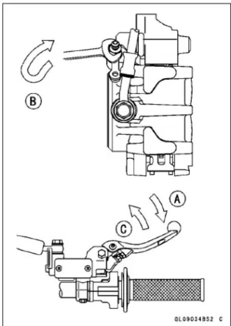
Brake Fluid
- Check the fluid level.
- After bleeding is done, check the brake for good braking power, no brake drag, and no fluid leakage.
WARNING
After servicing, it takes several applications of the brake lever or pedal before the brake pads contact the disc, which could result in increased stopping distance and cause an accident resulting in injury or death. Do not attempt to ride the motorcycle until a firm brake lever or pedal is obtained by pumping the lever or pedal until the pads are against the disc
Caliper
Caliper Removal
Front Brake
- Loosen the banjo bolt [A] so as not to spill brake fluid.
- Remove the caliper mounting bolts [B].
- Remove the banjo bolt and take off the brake hose from the caliper [C].
- If the caliper is to be disassembled after removal and if compressed air is not available, remove the piston using the following steps before disconnecting the brake hose from the caliper.
○Remove the pads.
○Pump the brake lever to remove the piston.
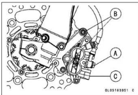
Rear Brake
- Unbolt the caliper guard bolts [A] and remove the caliper guard [B].
- Unbolt the disc guard bolts [C] and remove the disc guard [D].
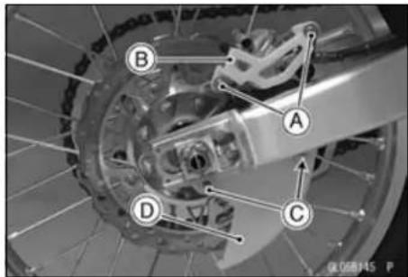
- Loosen the banjo bolt [A] so as not to spill brake fluid.
- Loosen the brake pad bolt plug[B], and pad bolt [C] before the caliper removal if the caliper is to be disassembled.
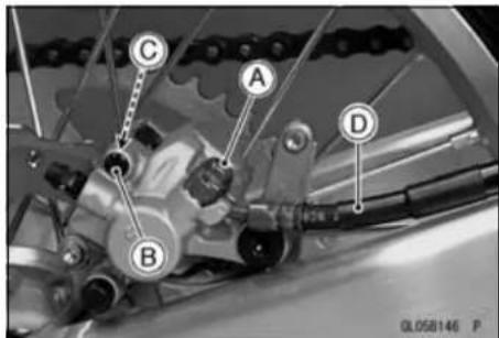
NOTE
○ If the caliper is to be disassembled after removal and compressed air is not available, disassemble the caliper before brake hose removal (see Caliper Disassembly).
- Remove the rear wheel (see Rear Wheel Removal in the Wheels/Tires chapter).
- Unscrew the banjo bolt and remove the brake hose [D] from the caliper (see Brake Hose Replacement in the Periodic Maintenance chapter).
NOTICE
Immediately wipe up any brake fluid that is spilled.
Caliper Installation
- Tighten the brake pad bolts if it was removed.
Torque - Brake Pad Bolt: 17 N·m (1.7 kgf·m, 13 ft·lb)
Front Brake
• Install the caliper and tighten the bolts.
Torque - Caliper Mounting Bolts: 25 N·m (2.5 kgf·m, 18 ft·lb)
Rear Brake
- Before install the caliper, install the rear wheel (see Rear Wheel Installation in the Wheels/Tires chapter).
• Install the brake hose lower end.
○Replace the washers that are on each side of hose fitting with new ones.
Torque - Brake Hose Banjo Bolt: 25 N·m (2.5 kgf·m, 18 ft·lb)
Caliper
- Bleed the brake line (see Bleeding the Brake Line).
- Check the brake for good braking power, no brake drag, and no fluid leakage.
WARNING
After servicing, it takes several applications of the brake lever or pedal before the brake pads contact the disc, which could result in increased stopping distance and cause an accident resulting in injury or death. Do not attempt to ride the motorcycle until a firm brake lever or pedal is obtained by pumping the lever or pedal until the pads are against the disc
Caliper Disassembly
- Refer to the Caliper Piston Seal and Dust Seal Replacement in the Periodic Maintenance chapter.
Fluid Seal Damage
The fluid seal around the piston maintains the proper pad/disc clearance. If this seal is not in good condition, pad wear will increase, and constant pad drag on the disc will raise brake and brake fluid temperature.
- Replace the fluid seals under any of the following conditions: (a) fluid leakage around the pad; (b) brakes overheat; (c) there is a large difference in left and right pad wear; (d) the seal is stuck to the piston. If the fluid seal is replaced, replace the dust seal as well. Also, replace all seals every other time the pads are changed.
Dust Seal and Cover Damage
- Check that the dust seals and covers are not cracked, worn, swollen, or otherwise damaged.
★If they show any damage, replace them.
Piston Cylinder Damage
- Visually inspect the piston and cylinder surfaces.
★Replace the cylinder and piston if they are badly scored or rusty.
Caliper Holder Shaft Wear
The caliper body must slide smoothly on the caliper holder shafts. If the body does not slide smoothly, one pad will wear more than the other, pad wear will increase, and constant drag on the disc will raise disc and brake fluid temperature.
- Check too see if the caliper holder shafts are not badly worn or stepped, or the rubber friction boot is not damaged.
★If the shafts or rubber friction boot are damaged, replace the shafts, rubber friction boot, and the caliper holder.
Caliper
Brake Pad Removal
Front Brake Pad
- Unscrew the pad bolt [A].
• Take the piston side pad [B]. - Push the caliper holder toward the piston, and then remove another pad [C] from the caliper holder.
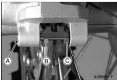
Rear Brake Pad
- Remove: Plug [A]
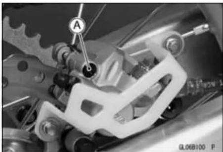
● Unscrew the pad bolt [A].
• Take the piston side pad [B].
- Push the caliper hold toward the piston, and then remove another pad [C] from the caliper holder.
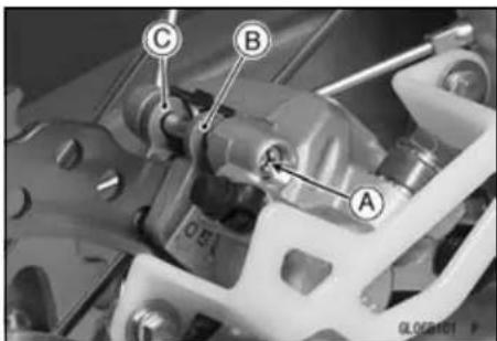
Brake Pad Installation
- Push the caliper pistons in by hand as far as they will go.
- Install the piston side pad first, and then another pad.
○Fit the pad end [A] into the groove [B] of the anti-rattle spring securely. - Tighten the brake pad bolt.
Torque - Brake Pad Bolt: 17 N·m (1.7 kgf·m, 13 ft·lb) Rear Brake Pad Bolt Plug: 2.4 N·m (0.24 kgf·m, 21 in·lb)
- Check the brake for good braking power, no brake drag, and no fluid leakage.
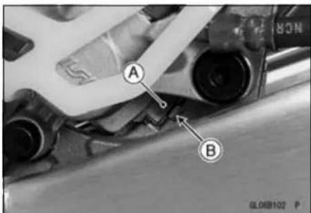
WARNING
After servicing, it takes several applications of the brake lever or pedal before the brake pads contact the disc, which could result in increased stopping distance and cause an accident resulting in injury or death. Do not attempt to ride the motorcycle until a firm brake lever or pedal is obtained by pumping the lever or pedal until the pads are against the disc.
Brake Pad Inspection
- Refer to the Brake Pad Wear Inspection in the Periodic Maintenance chapter.
Master Cylinder
NOTICE
Brake fluid quickly ruins painted or plastic surfaces; any spilled fluid should be completely wiped up immediately.
Front Master Cylinder Removal
- Remove the banjo bolt [A] to disconnect the upper brake hose [B] from the master cylinder [C].
- When removing the brake hose, temporarily secure the end of the brake hose to some high place to keep fluid loss to a minimum.
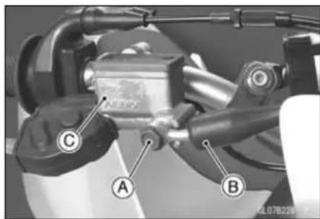
- Unscrew the clamp bolts [A], and take off the master cylinder [B] as an assembly with the reservoir and brake lever.
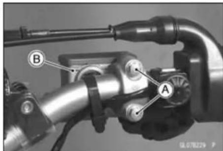
Front Master Cylinder Installation
- Install the master cylinder so that the reservoir cap [A] is horizontally.
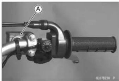
- The master cylinder clamp must be installed with the arrow mark [A] upward. ○Tighten the upper clamp bolt [B] first, and then the lower clamp bolt [C]. There will be a gap at the lower part of the clamp after tightening.
Torque - Front Master Cylinder Clamp Bolts: 8.8 N·m (0.90 kgf·m, 78 in·lb)
- Replace the washers that are on each side of hose fitting with new ones.
- Tighten the brake hose banjo bolt.
Torque - Brake Hose Banjo Bolt: 25 N·m (2.5 kgf·m, 18 ft·lb)
- Bleed the brake line (see Bleeding the Brake Line).
- Check the brake for good braking power, no brake drag, and no fluid leakage.
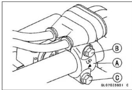
Rear Master Cylinder Removal
- Remove the cotter pin [A].
- Pull off the joint pin [B] with washer.
NOTE
○ Pull off the joint pin while pressing down the brake pedal.
- Unscrew the master cylinder mounting bolts [C], and remove the master cylinder [D].
- Unscrew the brake hose banjo bolt [E].
- When removing the brake hose, temporarily secure the end of the brake hose to some high place to keep fluid loss to a minimum.
Rear Master Cylinder Installation
- Replace the cotter pin with a new one.
- Replace the washers are on each side of hose fitting with new ones.
- Tighten the following:
Torque - Brake Hose Banjo Bolt: 25 N·m (2.5 kgf·m, 18 ft·lb)
Rear Master Cylinder Mounting Bolts: 10 N·m (1.0 kgf·m, 89 in·lb)
- Bleed the brake line (see Bleeding the Brake Line).
- Check the brake for good braking power, no brake drag, and no fluid leakage.
- Check the brake pedal position (see Brake Lever and Pedal Position Adjustment in the Periodic Maintenance chapter).
Front Master Cylinder Disassembly
- Refer to the Brake Master Cylinder Cup and Dust Seal Replacement in the Periodic Maintenance chapter.
Rear Master Cylinder Disassembly
- Refer to the Brake Master Cylinder Cup and Dust Seal Replacement in the Periodic Maintenance chapter.
Master Cylinder Assembly
- Refer to the Brake Master Cylinder Cup and Dust Seal Replacement in the Periodic Maintenance chapter.
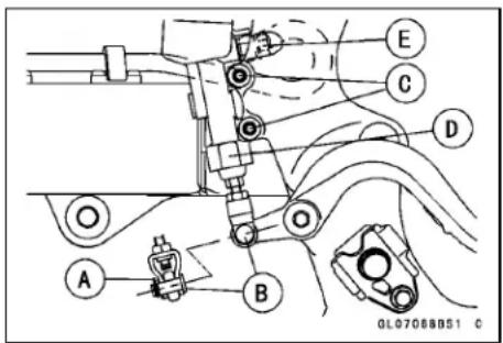
Master Cylinder
Master Cylinder Inspection (Visual Inspection)
- Disassemble the front and rear master cylinders. - Check that there are no scratches, rust or pitting on the inner wall of each master cylinder [A] and on the outside of each piston [B].
★If a master cylinder or piston shows any damage, replace them.
- Inspect the primary [C] and secondary [D] cups.
★If a cup is worn, damaged, softened (rotted), or swollen, the piston assembly should be replace to renew the cups.
★If fluid leakage is noted at the brake lever, the piston assembly should be replaced to renew the cup.
- Check the dust covers [E] for damage.
★If they are damaged, replace them.
- Check that the relief [F] and supply [G] ports are not plugged.
★If the small relief port becomes plugged, the brake pads will drag on the disc. Blow the ports clean with compressed air.
- Check the piston return springs [H] for any damage.
★If a spring is damaged, replace it.
[J] Front Master Cylinder [K] Rear Master Cylinder
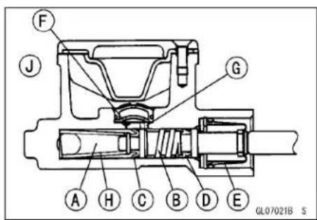
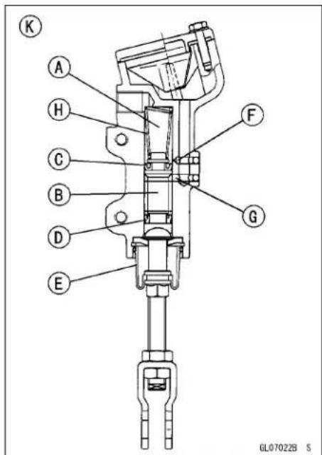
Brake Disk
Brake Disc Removal
- Remove the wheel (see Front/Rear Wheel Removal in the Wheels/Tires chapter).
- Unscrew the mounting bolts [A], and take off the disc [B].
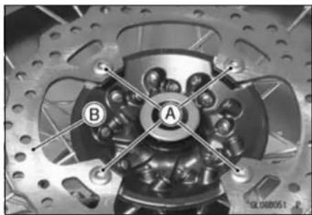
Brake Disc Installation
- Install the disc on the wheel so that the marked side [A] faces out.
- Apply a non-permanent locking agent to the threads of the brake disc bolts [B].
- Tighten:
Torque - Front Brake Disc Mounting bolts: 10 N·m (1.0 kgf·m, 89 in·lb)
Rear Brake Disc Mounting bolts: 23 N·m (2.3 kgf·m, 17 ft·lb)
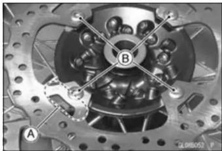
Brake Disclnspection
- Visually inspect the disc [A].
★If it is scratched or damaged, replace the disc. - Measure the thickness of each disc at the point [B] where it has worn the most.
★Replace the disc if it has worn past the service limit.
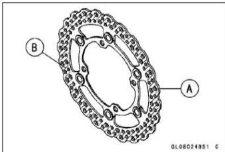
Thickness
Standard:
Front 2.85 \~ 3.15 mm (0.112 \~ 0.124 in.)
Rear 3.85 \~ 4.15 mm (0.152 \~ 0.163 in.)
Service Limit:
Front 2.5 mm (0.10 in.)
Rear 3.5 mm (0.14 in.)
- Place a jack under the motorcycle so that the front/rear wheel is raised off the ground.
Special Tool - Jack: 57001-1238
- Set up a dial gauge against the disc [A] as illustrated.
○For the front disc, turn the handlebar fully to one side.
- Measure the disc runout while rotating the wheel slowly [B].
★If the runout exceeds the service limit, replace the disc.
Runout
Standard: TIR 0.25 mm (0.0098 in.) or less
Service Limit: TIR 0.3 mm (0.01 in.)
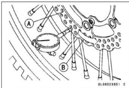
Brake Hose
Brake Hose Removal/Installation
- Refer to the Brake Hose Replacement in the Periodic Maintenance chapter.
Brake Hose Inspection
- Refer to the Brake Hose and Connection Check in the Periodic Maintenance chapter.
Suspension
Table of Contents
Exploded View.... 13-2
Specifications 13-6
Special Tools 13-7
Front Fork 13-8
Air Pressure 13-8
Rebound Damping Adjustment.... 13-8
Compression Damping Adjustment 13-9
Oil Change (each fork leg) 13-9
Front Fork Removal 13-9
Front Fork Installation 13-10
Front Fork Disassembly (each fork leg) 13-11
Front Fork Assembly 13-15
Adjuster Assembly Inspection.... 13-20
Base Valve Assembly Inspection 13-20
Cylinder Unit Inspection 13-21
Inner Tube Inspection 13-21
Guide Bush Inspection.... 13-21
Dust Seal/Oil Seal Inspection 13-21
Spring Tension 13-22
Rear Suspension (Uni-Trak) 13-23
Rear Shock Absorber: 13-23
Rebound Damping Adjustment.... 13-23
Compression Damping Adjustment 13-23
Spring Preload Adjustment 13-24
Spring Tension 13-25
Rear Shock Absorber Removal 13-26
Rear Shock Absorber Installation 13-26
Spring Replacement 13-26
Rear Shock Absorber Disassembly (Oil Change).... 13-27
Rear Shock Absorber Assembly.... 13-27
Rear Shock Absorber Scrapping 13-27
Swingarm.... 13-28
Swingarm Removal 13-28
Swingarm Installation.... 13-29
Swingarm Bearing Removal 13-29
Swingarm Bearing Installation 13-29
Swingarm Bearing, Sleeve Inspection 13-30
Drive Chain Guide, Guide Roller, Chain Slipper Wear.... 13-30
Tie-Rod, Rocker Arm.... 13-31
Tie-Rod Removal 13-31
Tie-Rod Installation 13-31
Rocker Arm Removal.... 13-31
Rocker Arm Installation.... 13-32
Tie-Rod and Rocker Arm Bearing Removal 13-32
Tie-Rod and Rocker Arm Bearing Installation.... 13-33
Needle Bearing Inspection.... 13-33
Uni-Trak Maintenance 13-34
Uni-Trak Linkage Inspection 13-34
Tie-Rod and Rocker Arm Sleeve Wear 13-34
Tie-Rod and Rocker Arm Mounting Bolt Bend 13-34
13-2 SUSPENSION
Exploded View
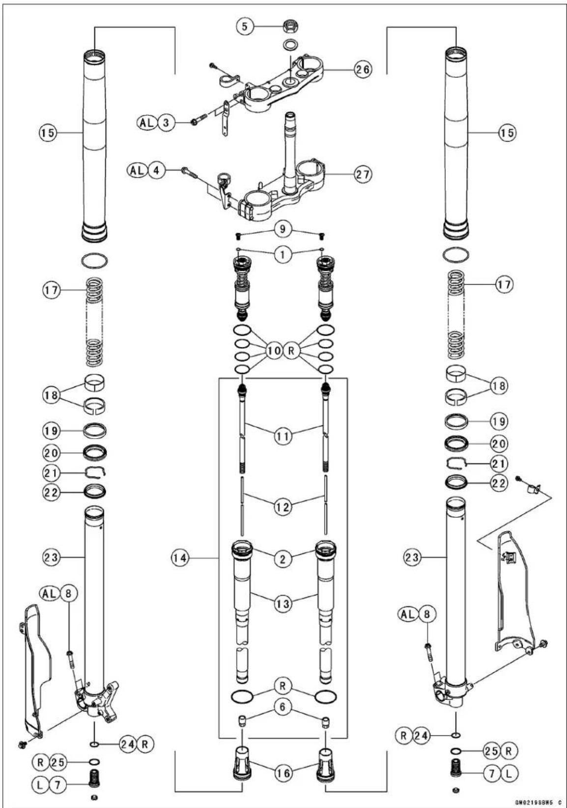
Exploded View
| No. | Fastener | Torque | Remarks | ||
| N·m kgf | ·m ft·lb | ||||
| 1 | Base Valve Assembly 28 2.9 21 | ||||
| 2 | Front Fork Top Plug | 30 | 3.1 | 22 | |
| 3 | Front Fork Clamp Bolts (Upper) | 20 2.0 | 15 AL | ||
| 4 | Front Fork Clamp Bolts (Lower) | 20 2.0 | 15 AL | ||
| 5 | Steering Stem Head Nut | 98 | 10 | 72 | |
| 6 | Locknut/Adjuster Assembly 29 3.0 21 | ||||
| 7 | Adjuster Assembly | 55 5.6 41 | L | ||
| 8 | Front Axle Clamp Bolts | 20 | 2.0 | 15 | AL |
-
Screw
-
O-ring
-
Piston Rod
-
Rebound Damping Adjuster Rod
-
Subtank
-
Cylinder Unit
-
Outer Tube
-
Spacer
-
Fork Spring
-
Bushings
-
Washer
-
Oil Seal
-
Retaining Ring
-
Dust Seal
-
Inner Tube
-
O-ring
-
Gasket
-
Steering Stem Head
-
Steering Stem
AL: Tighten the two clamp bolts alternately two times to ensure even tightening torque.
L: Apply a non-permanent locking agent to the threads.
R: Replacement Parts
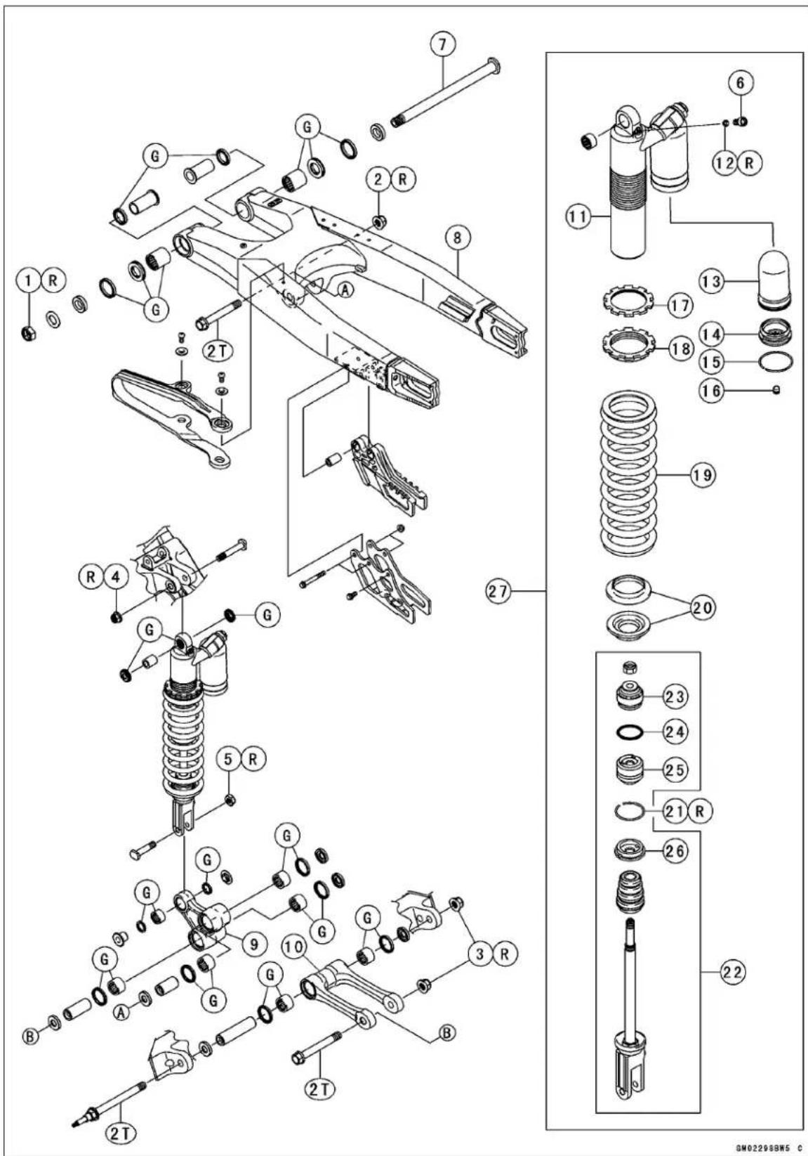
Exploded View
| No. | Fastener | Torque | Remarks | ||
| N·m kgf | f·m ft·lb | ||||
| 1 | Swingarm Pivot Shaft Nut 98 10 72 R | ||||
| 2 | Rocker Arm Pivot Nut | 59 | 6.0 | 44 | R |
| 3 | Tie-rod Mounting Nut (Front, Rear) | 59 | 6.0 | 44 | R |
| 4 | Rear Shock Absorber Mounting Nut (Upper) | 39 | 4.0 | 29 | R |
| 5 | Rear Shock Absorber Mounting Nut (Lower) | 34 | 3.5 | 25 | R |
| 6 | Air Bleed Bolt | 6.5 | 0.66 | 58 in·lb | |
-
Swingarm Pivot Shaft
-
Swingarm
-
Rocker Arm
-
Tie-Rod
-
Rear Shock Absorber Cylinder
-
O-ring
-
Bladder
-
Cap
-
Circlip
-
Valve Cap
-
Locknut
-
Adjusting Nut
-
Spring
-
Spring Guides
-
Circlip
-
Piston Rod Assembly
-
Piston
-
O-ring
-
Oil Seal
-
Stopper
-
Rear Shock Absorber
G: Apply grease.
L: Apply a non-permanent locking agent.
R: Replacement Parts
2T: Apply 2-stroke oil.
Specifications
| Item Standard Service Limit | ||
| Front Fork | ||
| Air Pressure Atmospheric pressure – Rebound Damping Adjustment(from the seated position adjuster turned fully clockwise)Compression Damping Adjustment(from the seated position adjuster turned fully clockwise)Oil Viscosity KHL15-10 (KAYABA 01) or oil Quantity:Outer (Outer/Inner Tubes)Inner (subtank)Fork Spring Free Length | – –9 clicks counterclockwise 18 clicks(Adjustable Range)11 clicks counterclockwise 22 clicks(Adjustable Range)335 mL (11.3 US oz.)189 mL (6.4 US oz.)460 mm (18.1 in.) | (Adjustable Range)– – –(Adjustable Range)300 ~ 380 mL(10.1 ~ 12.8 US oz.)– – –451 mm (17.8 in.) |
| Rear Suspension (Uni-Trak):Rear Shock Absorber | ||
| Rebound Damping Adjustment(from the seated position adjuster turned fully clockwise)Spring Preload Adjustment(Adjusting nut position from the center of the mounting hole upper)Rear Shock Spring Free Length | 9 clicks counterclockwise 22 clicks123.5 mm (4.86 in.)260 mm (10.2 in.) | (Adjustable Range)(Adjustable Range)121.5 ~ 138.5 mm(4.783 ~ 5.453 in.)255 mm (10.0 in.) |
| Gas Reservoir | ||
| High Speed CompressionDamping AdjustmentLow Compression Damping Adjustment(from the seated position adjuster turned fully clockwise)Gas PressureTie-Rod, Rocker ArmSleeve Outside Diameter:Tie-rod | 1-1/4 turn out11 clicks counterclockwise 22 clicks1 000 kPa ( 10 kgf/cm2 , 145 psi) | (Adjustable Range)0 ~ 2 turn out(Adjustable Range)– – – |
Special Tools
Oil Seal & Bearing Remover: 57001-1058
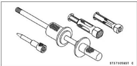
Steering Stem Nut Wrench: 57001-1100
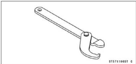
Hook Wrench R37.5, R42: 57001-1101
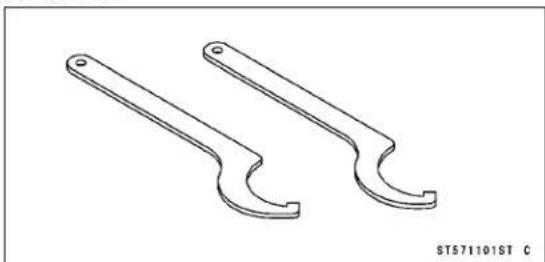
Bearing Driver Set: 57001-1129
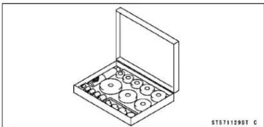
Jack: 57001-1238
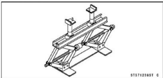
Bearing Remover Shaft, 9157001-1265
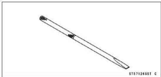
Bearing Remover Head, 1/5 × 17φ 57001-1267
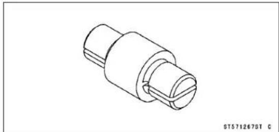
Fork Oil Seal Driver, 48: 57001-1509
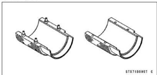
Top Plug Wrench, 49 mm: 57001-1653
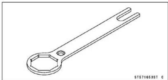
13-8 SUSPENSION
Front Fork
Air Pressure
The standard air pressure in the front fork legs is atmospheric pressure. Air pressure in the fork legs increase with normal use, so the fork action stiffens during operation. Release air pressure form the fork legs prior to each race through the pressure relief screw located in each front fork cap.
- Place the jack under the frame so that the front wheel off the ground.
Special Tool - Jack: 57001-1238
- Remove the screws [A] at the top of the front fork top plugs to let the air pressure equalize.
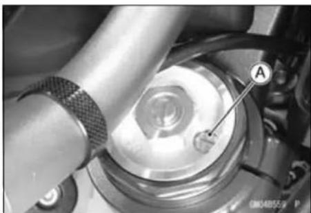
NOTE
○Do not use the sidestand when adjusting the air pressure.
○Adjust the air pressure when the front forks are cold.
- Replace the O-ring with a new one.
- Install the screw.
Rebound Damping Adjustment
- Place the jack under the frame so that the front wheel off the ground.
Special Tool - Jack: 57001-1238
- Clean the bottom of the fork tubes.
- Remove the caps on the bottom of the fork tubes.
- To adjust rebound damping, turn the adjuster [A] on the front fork cylinder valve with the blade of a screwdriver until you feel a click. Adjust the rebound damping to suit your preference under special condition.
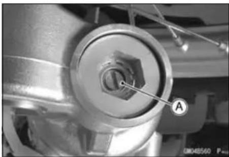
NOTE
○ The left and right fork legs must have the same shock damping.
Seated positions adjuster turned fully clockwise [A].
Rebound Damping Adjuster Setting
Standard: 9 clicks [B]
Softer (Counterclockwise) [C]
Harder (Clockwise) [D]
*: Number of turns counterclockwise usable range - 18 clicks or more.
Counterclockwise from the fully seated position.
- Put the caps into the bottom of the fork tubes.
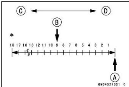
Front Fork
Compression Damping Adjustment
- Place the jack under the frame so that the front wheel off the ground.
Special Tool - Jack: 57001-1238
- To adjust compression damping, turn the adjuster [A] on the front fork top plugs with the blade of a screwdriver until you feel a click. Adjust the compression damping to suit you preference under special condition.
NOTE
○ The left and right fork legs must have the same shock damping.
Seated positions: adjuster turned fully clockwise [A].
Compression Damping Adjuster Setting
Standard: 11 clicks [B] Softer (Counterclockwise) [C] Harder (Clockwise) [D]
*: Number of turns counterclockwise usable range - 22 clicks or more. Counterclockwise from the fully seated position.
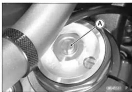
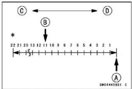
Oil Change (each fork leg)
- Refer to Front Fork Oil Change in the Periodic Maintenance chapter.
Front Fork Removal
- Unscrew the bolts [A], and remove the front brake hose clamps [B].
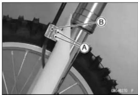
- Remove: Front Wheel (see Front Wheel Removal in the Wheels/Tires chapter) Master Cylinder Camp Bolts [A]
- Remove the caliper [B] from the fork leg to be removed, and restthe caliper on some kind of stand so that it doesn't dangle.
- Remove: Bolts [C] Fork Protector [D]
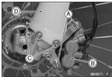
13-10 SUSPENSION
Front Fork
- Loosen the upper [A], and lower [B] fork clamp bolts.
- Remove the front fork.
With a twisting motion [A], work the fork leg [B] down and out.
Front Fork Installation
- Install the fork so that the distance between the top end of the outer tube and the upper surface of the steering stem head is specified dimension.
[A] 8 mm (0.31 in.)
- Route the cables and hose according to the Cable, Wire, and Hose Routing section in the Appendix chapter.
- Install the front wheel (see Front Wheel Installation in the Wheels/Tires chapter).
- Tighten the fork clamp bolts.
Torque - Front Fork Clamp Bolts (Upper): 20 N·m (2.0 kgf·m, 15 ft·lb)
Front Fork Clamp Bolts (Lower): 20 N·m (2.0 kgf·m, 15 ft·lb)
NOTE
○ Tighten the two clamp bolts alternately two times to ensure even tightening torque.
- Tighten:
Torque - Front Caliper Mounting Bolts: 25 N·m (2.5 kgf·m, 18 ft·lb)
- Check the front brake operation after installation.
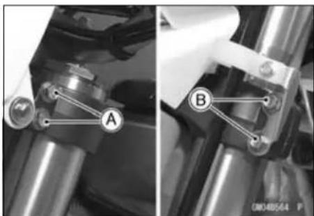
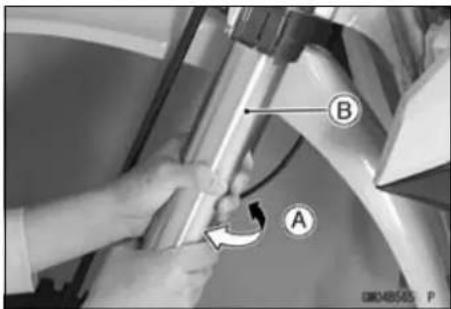
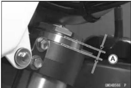
Front Fork
Front Fork Disassembly (each fork leg)
- Loosen the front fork upper clamp bolts [A].
- Loosen the fork top plug (subtank) [A] with the top plug wrench [B].
Special Tool - Top Plug Wrench, 49 mm: 57001-1653 [B]
- Remove the front fork (see Front Fork Removal).
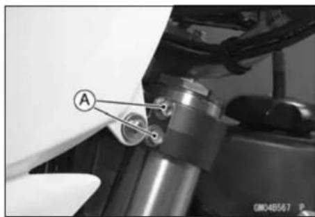
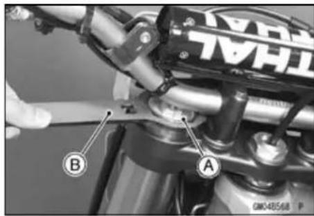
NOTE
○ Set rebound and compression damping setting to the softest settings before disassembling to prevent the needle of adjusters from damaging. Record the setting before turning the adjuster.
- Thoroughly clean the fork before disassembly.
NOTICE
Be careful not scratch the inner tube and not to damage the dust seal.
Avoid scratching or damaging the inner tube or the dust seal. Use a mild detergent and sponge out dirt with plenty of water.
- Using the top plug wrench [A], remove the fork top plug [B] (subtank) from the outer tube and slowly slide down the outer tube [C].
Special Tool - Top Plug Wrench, 49 mm: 57001-1653
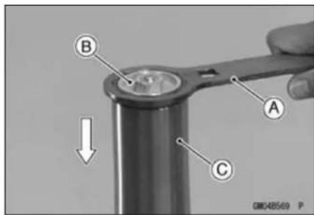
13-12 SUSPENSION
Front Fork
- Place a drain pan under the front fork and drain fork oil [A].
NOTE
○Pump the fork tube several times to discharge the fork oil.
- Raise the outer tube and temporarily install the fork top plug [A] (subtank) to the outer tube [B] with the top plug wrench [C].
Special Tool - Top Plug Wrench, 49 mm: 57001-1653
- Hold the axle holder [A] with a vise.
○Protect the axle holder with a rag when using a vise. - Loosen the adjuster assembly [B] completely.
WARNING
Clamping the axle holder part too tight can damage it which will affect riding stability. Do not clamp the axle holder part too tight.
- Compress the outer tube by hands and install the top plug wrench [A] between theaxle holder bottom [B] and locknut [C].
Special Tool - Top Plug Wrench, 49 mm: 57001-1653
WARNING
The fork spring applies pressure to the adjuster assembly and can eject the special tool with substantial force if the tool is not properly and securely placed. Be sure the tool is fully in place as shown in the photo, and keep fingers away to avoid getting them pinched between the tool, adjuster assembly and axle holder.
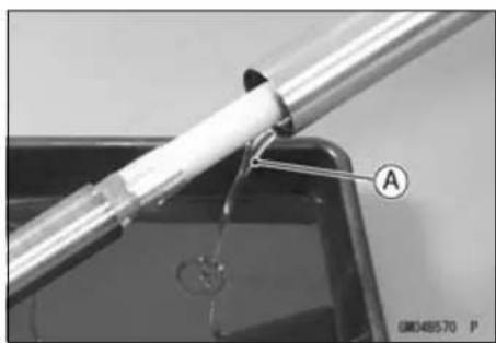
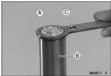
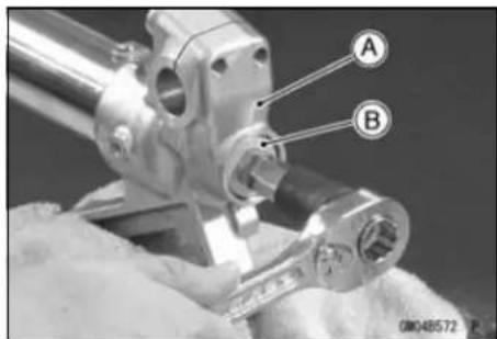
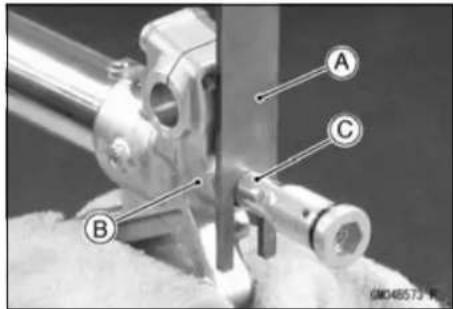
Front Fork
- Hold the locknut [A] with a wrench [B] and remove the adjuster assembly [C].
- Remove the push rod [A].
- With the outer tube compressed by hands, remove the topplugwrench[A].
NOTICE
Removing the locknut and pushing the piston rod thread into the cylinder unit will damage the oil seal. Do not remove the locknut from the piston rod.
- Remove the fork leg from the vise.
- Loosen the fork top plug (subtank) [A] with the top plug wrench [B].
Special Tool - Top Plug Wrench, 49 mm: 57001-1653 [B]
- Remove:
Cylinder Unit [A]
Spacer [B]
Fork Spring [C]
NOTICE
Disassembling the cylinder unit can lead to trouble. Do not disassemble the cylinder unit.
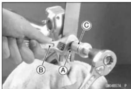
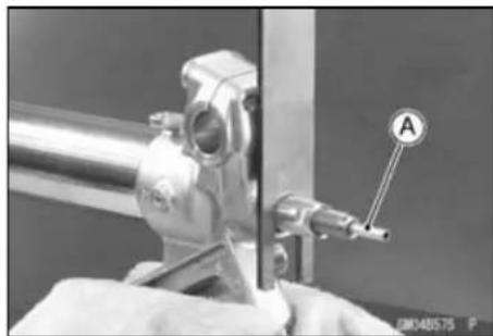

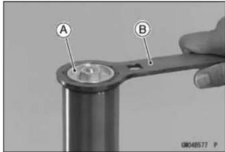
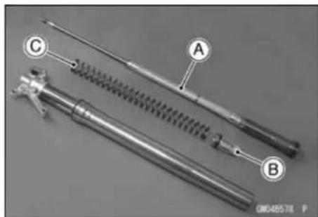
13-14 SUSPENSION
Front Fork
- Remove the dust seal [A] and the retaining ring [B].
NOTICE
Be careful not to scratch the inner tube.
- Grasp the outer tube and stroke [A] the inner tube several times. The shock to fork seal separates the inner tube from the outer tube.
- Remove the following parts from the inner tube.
[A] Guide Bushes
[B] Washer
[C] Oil Seal
[D] Retaining Ring
[E] Dust Seal
- Holding the top plug wrench [A] with a vise, loosen the base assembly [B] on the subtank [C].
Special Tool - Top Plug Wrench, 49 mm: 57001-1653
- Remove the base valve assembly [A] from the subtank [B].
NOTE
○ Slowly compress the piston rod until it stops so that the base valve assembly can be removed easily.
NOTICE
Disassembling the base valve assembly can lead to trouble.
Do not disassemble the base valve assembly.
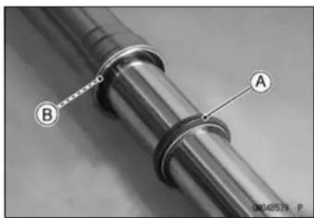
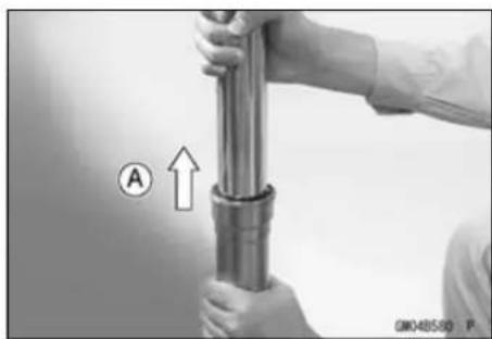
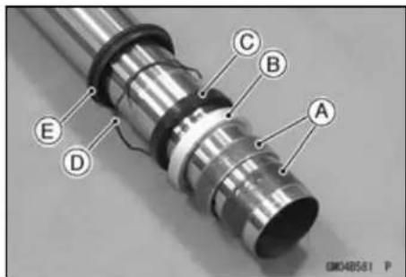
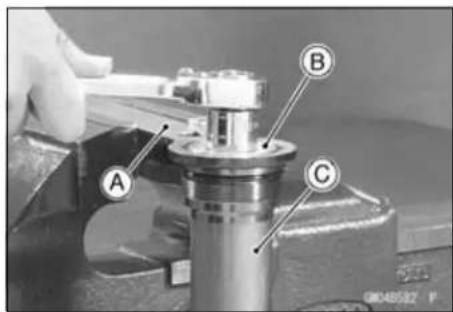
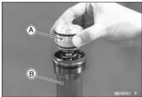
Front Fork
- Drain the fork oil [A] from the cylinder unit [B] by pumping the piston rod several times.
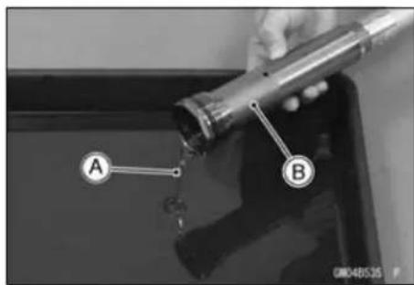
Front Fork Assembly
- When the fork tubes are not disassembled, hold the fork inverted position for more than 20 minutes to allow the fork oil to fully drain.
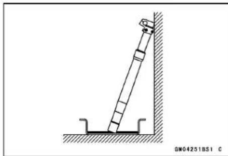
- Replace the following with new ones:
Dust Seal [A]
Retaining Ring [B]
Oil Seal [C]
Guide Bushes [D]
- Place an oil coated plastic bag [E] over the end of the inner tube to protect the oil seals.
The inner tube guide bush groove has a sharp edge [F] that can out the sealing lip of the seals as they as are pushed down over the inner tube. - Install in order these parts on the inner tube.
- When assembling the new outer tube guide bush [A], hold the washer against the new one, and tap the washer with the fork oil seal driver [B] until it stops.
Special Tool - Fork Oil Seal Driver, φ48: 57001-1509
- After installing the washer, install the oil seal by using the fork oil seal driver.
Special Tool - Fork Oil Seal Driver, φ48: 57001-1509
- Install the retaining ring to the outer tube.
- Push the dust seal into the outer tube, and put the spring band on the dust seal.
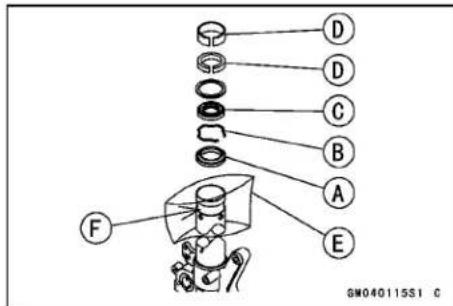
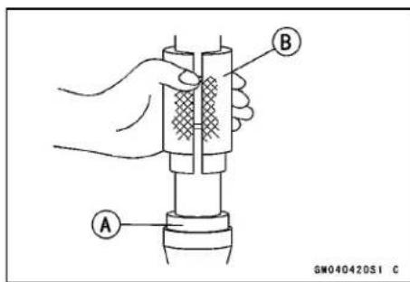
13-16 SUSPENSION
Front Fork
- Clean the threads [A] of subtank and base valve assembly.
- With the piston rod in fully compressed position, pour the specified amount of fork oil [A].
Recommended Oil: KHL15-10 (KAYABA01) or equivalent
Recommended Quantity: 189 ml (6.4 US oz.)
NOTE
○ Plug the two oil holes on the subtank [B] with fingers.
- Pump [A] the piston rod [B] slowly several times to expel air.
- Replace the O-rings [A] on the base valve assembly with new ones.
- Apply specified fork oil to the O-rings [A] [B] and bushings [C] on the base valve assembly.
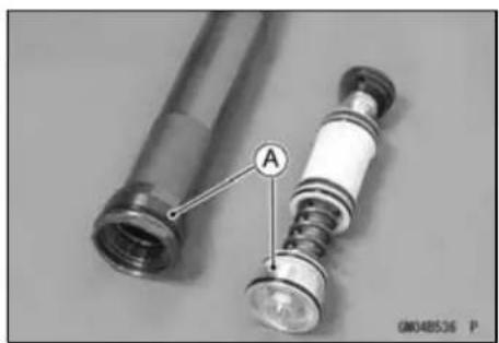
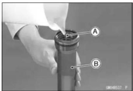
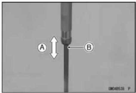
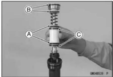
Front Fork
- With the piston rod held immorable in position [A], gently install the base valve assembly [B] to the subtank.
- Screw in the base valve assembly in the subtank when the piston rod extends.
NOTE
○ When it is hard to screw in the base valve assembly, pull down the piston rod a little.
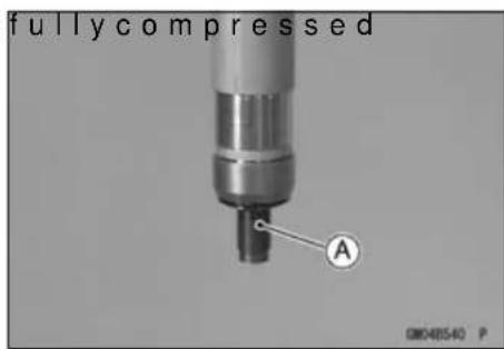
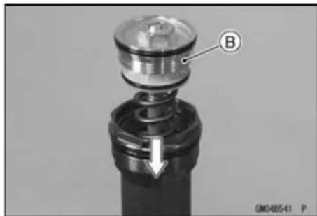
- Holdingthetopplugwrench[A]withavis
- Holding the subtank [B] with the top plug wrench, torque the base valve assembly [C].
Special Tool - Top Plug Wrench, 49 mm: 57001-1653
Torque - Base Valve Assembly: 28 N·m (2.9 kgf·m, 21 ft·lb)
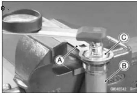
- Protect the piston rod end [A] with a rag [B] to prevent fork damage.
- Discharge the extra oil off the cylinder unit by pumping [C] the piston rod to full stroke.
NOTICE
Be careful not to bend or damage the piston rod when the piston rod is stroked. Service carefully because oil flies out from the oil hole of the cylinder unit.
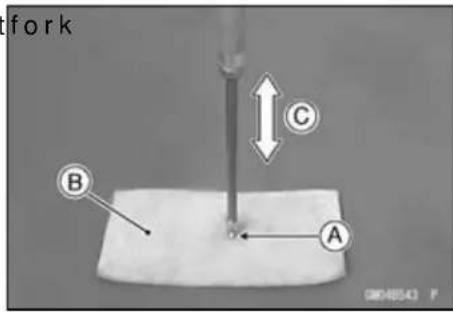
NOTE
○ Set the compression damper setting to the softest.
○ Check the piston rod sliding surface for damage.
○Apply fork oil to the piston rod sliding surface.
13-18 SUSPENSION
Front Fork
- Drain the extra oil from the subtank oil hole [A].
- With the cylinder unit in horizontal position, move [A] the piston rod [B] by hand to inspect it if operating smoothly. - If the piston rod is not extend, remove the base valve assembly and perform the air bleeding (pour the specified amount fork oil and discharge an excess of oil).
- Completely wipe of the fork oil from the spring [A], spacer [B] and cylinder unit [C]. - Insert above-mentioned parts into the fork.
- Temporarily tighten the fork top plug [A] (subtank) using the top plug wrench. Special Tool - Top Plug Wrench, 49 mm: 57001-1653 [B]
- Clamp the axle holder with a vise. - Protect the axle holder with a rag when using a vise.
WARNING
Clamping the axle holder part too tight can damage it which will affect riding stability. Do not clamp the axle holder part too tight.
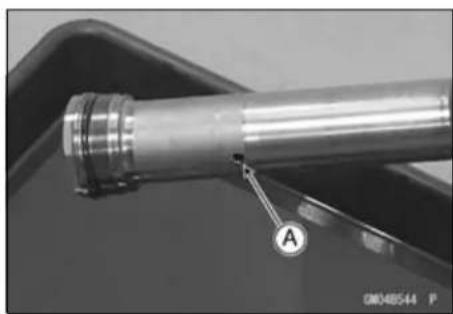
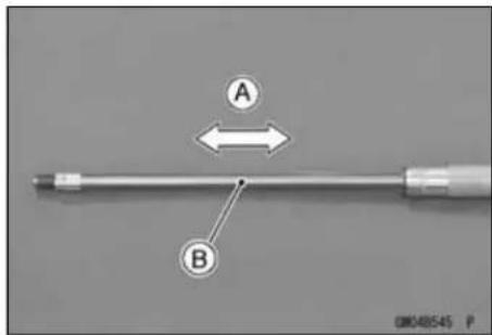
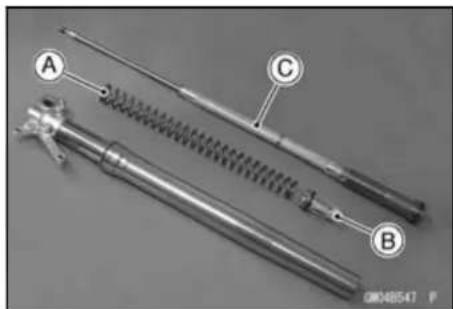
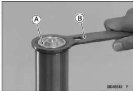
Front Fork
- Compress the outer tube by hands and install the top plug wrench [A] between the axle holder bottom and locknut. Special Tool - Top Plug Wrench, 49 mm: 57001-1653
WARNING
The fork spring applies pressure to the adjuster assembly and can eject the special tool with substantial force if the tool is not properly and securely placed. Be sure the tool is fully in place as shown in the photo, and keep fingers away to avoid getting them pinched between the tool, adjuster assembly and axle holder.
- Insert the push rod [A] into the piston rod.
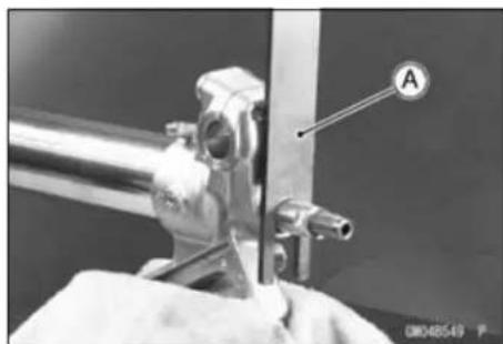
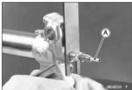
- Replace the O-ring and gasket on the adjuster assembly with new ones and apply specified fork oil to the O-ring. - Turn the locknut [A] counterclockwise until it contacts with the adjuster assembly [B]. - With the locknut held immovable using a wrench, tighten the adjuster assembly to the specified torque.
Torque - Locknut/Adjuster Assembly: 28 N·m (2.9 kgf·m, 21 ft·lb)
- With the outer tube compressed by hands, remove the top plug wrench.
- Apply a non-permanent locking agent to the threads of adjuster assembly.
- Torque the adjuster assembly [A]. Torque - Adjuster Assembly: 55 N·m (5.6 kgf·m, 41 ft·lb)
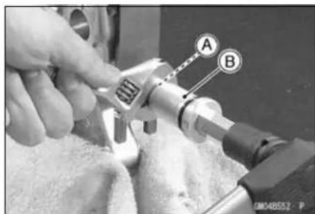
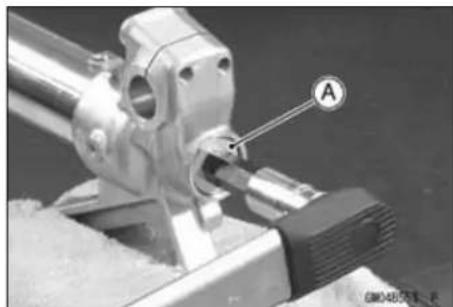
Front Fork
- Loosen and remove the fork top plug (subtank) form the outer tube and slowly slide down the outer tube.
Special Tool - Top Plug Wrench, 49 mm: 57001-1653 - Pour [A] the specified amount of fork oil into the outer tube.
Recommended Oil: KHL15-10 (KAYABA01) or equivalent
Recommended Quantity: 335 mL (11.3 US oz)
- Raise the outer tube and temporarily tighten the fork top plug (subtank).
Special Tool - Top Plug Wrench, 49 mm: 57001-1653
● After installing the front fork, torque the top plug [A].
Special Tool - Top Plug Wrench, 49 mm: 57001-1653 [B]
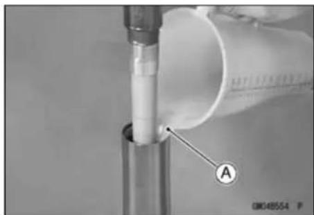
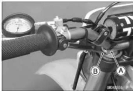
The torque of fork top plug is specified to 30 N·m (3.1 kgf·m, 22 ft·lb), however, w hen you use the top plug wrench (special tool) [A] reduce the torque to 90% of the specified value [27 N·m (2.8 kgf·m, 20 ft·lb)] due to the distance [B] between the center of the square hole, where the torque wrench is fitted, and that of the octagonal hole of the wrench.
This torque value [27 N·m (2.8 kgf·m, 20 ft·lb)] is applicable when you use a torque wrench whose length gives leverage of approximately 310 mm between the grip point to the center of the coupling square.
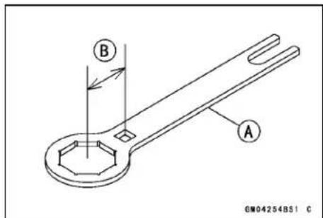
Adjuster Assembly Inspection
- Inspect the adjuster assembly [A] and push rod [B] for damage.
★If they are damaged, replace them with new ones. - Replace the gasket [C] and O-ring [D] on the adjuster assembly with new ones.
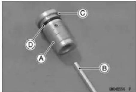
Base Valve Assembly Inspection
- Inspect the threads portion [A], bushing [B] and spring [C] of base valve assembly [D] for damage.
★If they are damaged, replace base valve assembly with new one. - Replace the O-rings [E] with new ones.
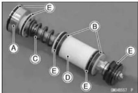
Front Fork
Cylinder Unit Inspection
- Inspect the piston rod [B] of cylinder unit [A] for scratches or bending.
★If it has scratches or is bent, replace cylinder unit with a new one.
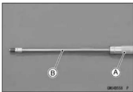
Inner Tube Inspection
- Visually inspect the inner tube [A], repair any damage.
- Nick or rust damage can sometimes be repaired by using a wet-stone to remove sharp edges or raised areas which cause seal damage.
★If the damage is not repairable, replace the inner tube. Since damage to the inner tube damages the oil seal, replace the oil seal whenever the inner tube is repaired or replaced.
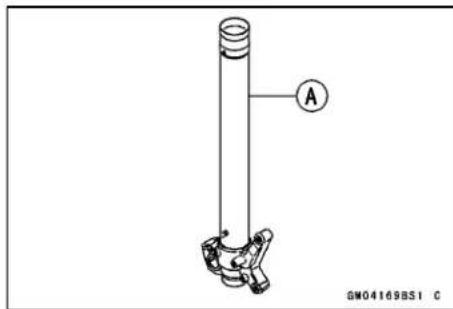
- Temporarily assemble the inner [A] and outer tubes [B], and pump them back and forth manually to check for smooth operation.
NOTICE
If the inner tube is badly bent or creased, replace it. Excessive bending, followed by subsequent straightening, can weaken the inner tube.
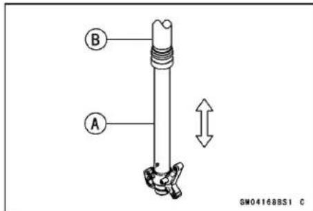
Guide Bush Inspection
- Visually inspect the guide bushes [A], and replace them if necessary.
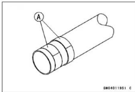
Dust Seal/Oil Seal Inspection
- Inspect the dust seal [A] for any signs of deterioration or damage.
★Replace it if necessary.
- Replace the oil seal [B] with a new one whenever it has been removed.
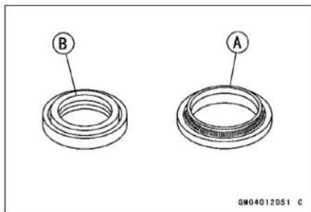
Front Fork
Spring Tension
- Since a spring becomes shorter as it weakens, check its free length [A] to determine its condition.
★If the spring of either fork leg is shorter than the service limit, it must be replaced. If the length of a replacement spring and that of the remaining spring vary greatly, the remaining spring should also be replaced in order to keep the fork legs balanced from motorcycle stability.
Fork Spring Free Length
Standard: 460 mm (18.1 in.)
Service Limit: 451 mm (17.8 in.)
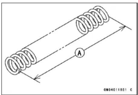
Rear Suspension (Uni-Trak)
Rear Shock Absorber:
The rear suspension system of this motorcycle is New Uni-trak. It consists of a rear shock absorber, swing arm, tie-rod and rocker arm.
To suit to various riding conditions, the spring preload of the shock absorber can be adjusted or the spring can be replaced with an optional one. Also the damping force can be adjusted easily so changing oil viscosity unnecessary.
Rebound Damping Adjustment
- Turn the rebound damping adjuster [A] on the rear shock absorber lower end with the blade of a screwdriver until you feel a click.
★If the damper setting feels too soft or too stiff, adjust it in accordance with the following table:
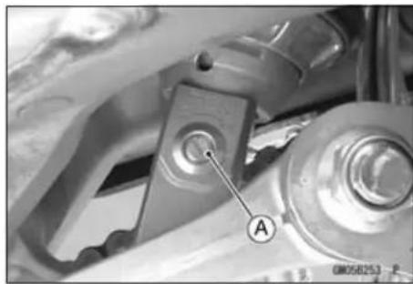
Seated position: adjuster turned fully clockwise [A].
Rebound Damping Adjuster Setting
Standard: 9 clicks [B] Softer (Counterclockwise) [C] Harder (Clockwise) [D]
*: Number of turns counterclockwise usable range - 22 or more. Counterclockwise from the fully seated position.
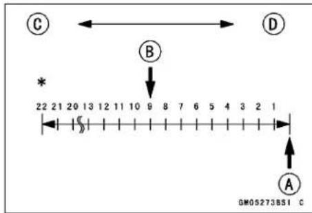
NOTE
○Adjustment of the rebound damping adjuster for the rear suspension will slightly affect the compression damping force. Always make any damping adjustments in small steps and test their effects before using them in competition.
Compression Damping Adjustment
There are two adjustments you can make to the rear shock absorber gas reservoir.
High Speed Compression Damping Adjuster [A] Low Speed Compression Damping Adjuster [B]
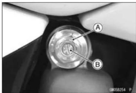
13-24 SUSPENSION
Rear Suspension (Uni-Trak)
- Adjust the high speed compression damping, turn the high speed compression damping adjuster with a 17 mm wrench.
★If the damping feels too soft or too stiff, adjust it in accordance with the following table.
High Speed Compression Damping
Standard: 1 1/4 turns out [B]
Softer (counterclockwise) [C]
Harder (clockwise) [D]
* : Number of turns counterclockwise usable range - 2 or more.
[A] Counterclockwise from the fully seated position.
- Adjust the low speed compression damping, turn the low speed compression damping adjuster with a flat-head screwdriver.
★If the damping feels too soft or too stiff, adjust it in accordance with the following table.
Low Speed Compression Damping
Standard: 11 clicks [B]
Softer (counterclockwise) [C]
Harder (clockwise) [D]
* : Number of turns counterclockwise usable range - 22 clicks or more.
[A] Counterclockwise from the fully seated position.
NOTE
○ Adjustment of the rebound damping adjuster for the rear suspension will slightly affect the compression damping force. Always make any damping adjustments in small steps and test their effects before using them in competition.
Spring Preload Adjustment
- Remove:
Seat (see Seat Removal in the Frame chapter) Side Covers (see Side Cover Removal in the Frame chapter)
Rear Frame (see Rear Frame Removal in the Frame chapter)
Carburetor Holder Clamp Screw (loosen) Muffler (see Muffler Removal in the Engine Top End chapter)
Rear Frame Mounting Bolts [A]
Rear Frame [B] with Air Cleaner Housing
- Using the jack under the frame, raise the rear wheel off the ground.
Special Tool - Jack: 57001-1238
![graph TD A["Hexagon"] --> B["A"] A --> C["C"] A --> D["D"] A --> E["*"] E --> F["Circle with arrow"] style A fill:#f9f,stroke:#333 style B fill:#ccf,stroke:#333 style C fill:#cfc,stroke:#333 style D fill:#fcc,stroke:#333 style E fill:#ffc,stroke:#333 style F fill:#cff,stroke:#333](/content/2026/05/818283/images/26ee6c3e317de6abb9efe8f5c116b83e66670b976b407d7deb0f07d81988ebad.jpg)
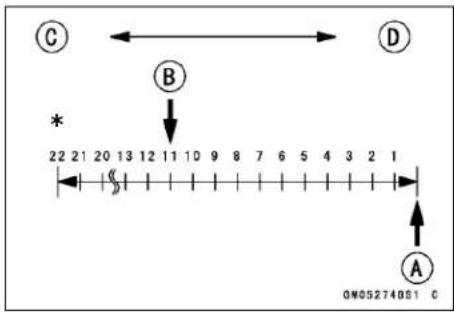
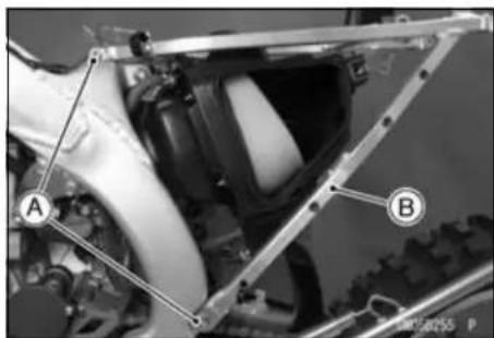
Rear Suspension (Uni-Trak)
- Using the hook wrenches [A], loosen the locknut [B] on the rear shock absorber.
Special Tool - Hook Wrench R37.5, R42: 57001-1101
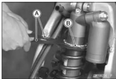
- Using the stem nut wrench [A], turn the adjusting nut [B] as required. Turning the adjusting nut downward marks the spring action harder and upward softer.
Special Tool - Steering Stem Nut Wrench: 57001-1101
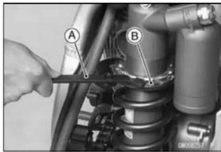
Spring Preload Adjustment
(Adjusting nut position at the lower surface [A] from the center of the mounting hole)
Standard: 123.5 mm (4.86 in.)
Adjustable Range 121.5 \~ 138.5 mm (4.783 \~ 5.453 in.)
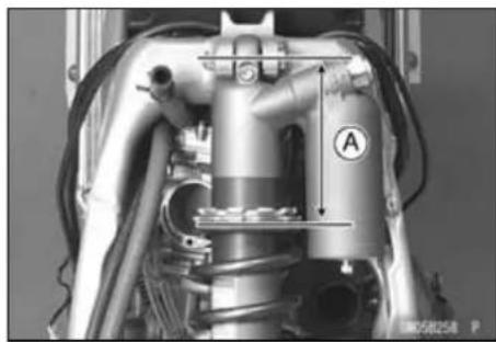
- Tighten the locknut securely.
- After adjusting, move the spring up and down to make sure that the spring is seated.
- Install the parts removed.
- Tighten the rear frame mounting bolts.
Torque - Rear Frame Mounting Bolts: 34 N·m (3.5 kgf·m 25 ft·lb)
Spring Tension
- Since the spring becomes shorter as it weakens, check its free length [A] to determine its condition.
★If the spring length is less than the service limit, replace the spring with a new one.
Shock Absorber Spring Free Length
Standard: 260 mm (10.2 in.)
Service Limit: 255 mm (10.0 in.)
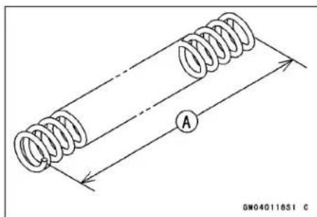
13-26 SUSPENSION
Rear Suspension (Uni-Trak)
Rear Shock Absorber Removal
- Remove:
Seat (see Seat Removal in the Frame chapter)
Side Covers (see Side Cover Removal in the Frame chapter)
Muffler (see Muffler Removal in the Engine Top End chapter)
Rear Frame with Air Cleaner Housing
- Using the jack under the frame, raise the rear wheel off the ground.
Special Tool - Jack: 57001-1238
NOTICE
When pulling out the mounting bolts, lift the rear wheel slightly. Forcing or tapping on a bolt could damage the bolt, sleeve, and bearing
- Remove the tie-rod rear mounting bolt and nut, and turn it downward.
- Remove the rear shock absorber lower mounting bolt [A] and nut.
- Remove the rear shock absorber upper mounting bolt [B], nut, and pull out the rear shock absorber [C] down and out.
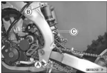
Rear Shock Absorber Installation
- Pack the rocker arm needle bearings with grease.
- Apply plenty of 2-stroke oil to the threads of the tie-rod front mounting bolts.
- Replace the rear shock absorber mounting nuts and tie -rod mounting nut with new ones.
- Tighten the following:
Torque - Rear Shock Absorber Mounting Nut (Upper): 39 N·m (4.0 kgf·m, 29 ft·lb)
Rear Shock Absorber Mounting Nut (Lower): 34 N·m (3.5 kgf·m, 25 ft·lb)
Rear Frame Mounting Bolts: 34 N·m (3.5 kgf·m, 25 ft·lb)
Tie-Rod Mounting Nut (Front): 59 N·m (6.0 kgf·m, 44 ft·lb)
• Install the removal parts.
Spring Replacement
In addition to the standard spring, heavy and light springs are available. If the standard spring is improper for your purpose, select a proper one according to the rider's weight or course conditions.
- Remove the rear shock absorber (see Rear Shock Absorber Removal).
- Clean the threaded portion on the upper of the rear shock absorber.
- Hold the lower of the rear shock absorber with a vise.
Rear Suspension (Uni-Trak)
- Using the hook wrenches [C], loosen the locknut [B] and turn the adjusting nut [A] all way up.
Special Tool - Hook Wrench R37.5, R42: 57001-1101
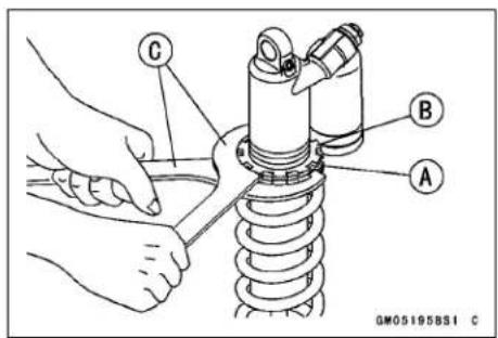
- Remove the rear shock absorber from the vise.
- Slide down the rubber bumper [A].
- Remove the spring guides [B] from the shock absorber and lift off the spring [C].
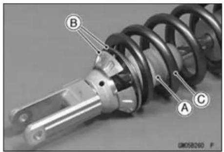
- Exchange the spring for an optional part. Install the spring so that closed coil large diameter end [A] faces upward.
• Install the spring guide. - Adjust the spring preload (see Spring Preload Adjustment).
- Install the rear shock absorber.
- Install the parts removed.
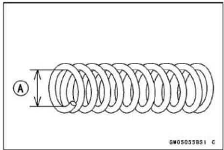
Rear Shock Absorber Disassembly (Oil Change)
- Refer to the Rear Shock Absorber Oil Change in the Periodic Maintenance chapter.
Rear Shock Absorber Assembly
- Refer to the Rear Shock Absorber Oil Change in the Periodic Maintenance chapter.
Rear Shock Absorber Scrapping
WARNING
When heated, pressurized gas may explode and cause serious injury or death. Since the rear shocks contains gas, do not incinerate them. Before discarding a rear shock, remove the air valve to prevent the possibility of explosion.
- Remove the shock absorber (see Rear Shock Absorber Removal).
- Remove the valve cap [A] and release the nitrogen gas completely from the gas reservoir.
- Remove the valve.
WARNING
Pressurized gas can cause injury. Do not point the valve toward your face or body.
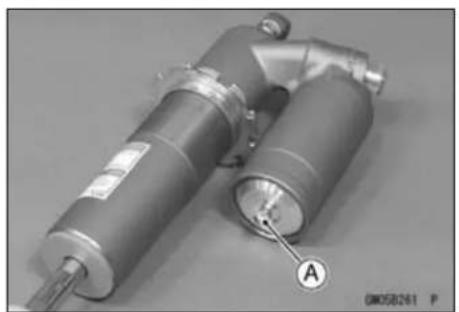
13-28 SUSPENSION
Swingarm
Swingarm Removal
- Place the jack [A] under the frame so that the rear wheel is off the ground.
Special Tool - Jack: 57001-1238
- Remove
Rear Wheel (see Rear Wheel Removal in the Wheels/Tires chapter)
Clamps [B]
Brake Pedal [C] (see Brake Pedal Removal in the Brakes chapter)
Disc Protector [D]
- Remove:
Bolts [A] and Nuts [B]
Chain Guide Plate [C]
Chain Guide [D]

- Unscrew the rocker arm pivot nut [A] and pull out the rocker arm pivot bolt [B].
NOTICE
When pulling out the mounting bolts, lift the swingarm slightly. Forcing or tapping on a bolt could damage the bolt, sleeve, and bearing.
- Unscrew the nut [A].
- Pull out the swingarm pivot shaft [B], and remove the swingarm [C].
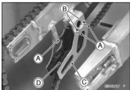
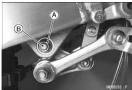
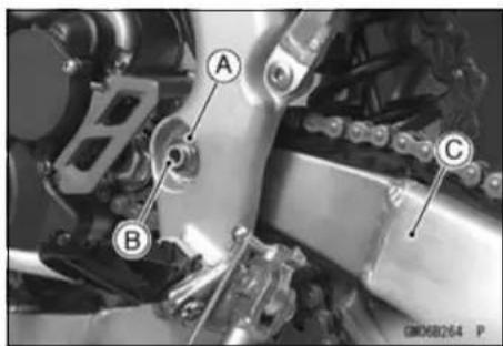
Swingarm
- Unscrew the screws [A]
- Separate the chain slipper [B] from the swingarm.
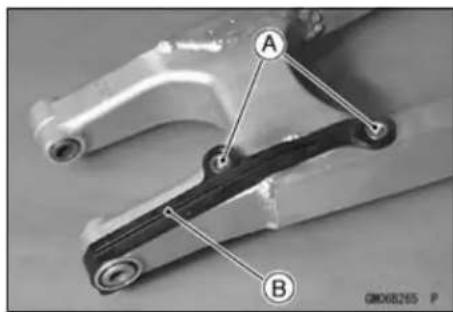
Swingarm Installation
- Apply plenty of grease to the inside of the needle bearings, sleeves, and oil seals.
- Replace the swingarm pivot shaft nut with a new one.
- Tighten the following:
Torque - Swingarm Pivot Shaft Nut: 98 N·m (10 kgf·m, 72 ft·lb)
Rocker Arm Pivot Nut: 59 N·m (6.0 kgf·m, 44 ft·lb)
- Refer to the Wheels/Tires, Final Drive, and Brakes chapters for wheel installing.
Swingarm Bearing Removal
- Remove:
Swingarm (see Swingarm Removal)
Collars [A]
Grease Seals [B]
Sleeves [C]
Needle Bearings [D]
- Remove the needle bearings [E] using the oil seal & bearing remover.
Special Tool - Oil Seal & Bearing Remover: 57001-1058
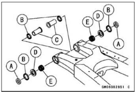
Swingarm Bearing Installation
- Replace the needle bearings and, grease seals with new ones.
- Apply plenty of grease to the sleeves, grease seals [C], and needle bearings [A] [B].
NOTE
○ Install the needle bearings so that the manufacturer's marks face out.
○ Install the grease seals so that the deep groove side of the rip in-ward.
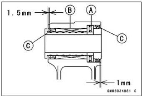
Special Tool - Bearing Driver Set: 57001-1129
- Install the needle bearings and grease seals position as shown.
○The installation procedure is the same as the counter side.
Swingarm
Swingarm Bearing, Sleeve Inspection
NOTICE
Do not remove the bearings for inspection. Removal may damage them.
- Inspect the needle bearings installed in the swingarm.
The rollers in a bearing normally wear very little, and wear is difficult to measure. Instead of measuring, visually inspect the bearing for abrasion, discoloration, or other damage.
★If the needle bearing, and sleeve show any sings of abnormal wear, discoloration, or damage, replace them as a set.
Drive Chain Guide, Guide Roller, Chain Slipper Wear
- Visually inspect the drive chain guide [A] and replace it if excessively worn or damaged.
- Visually inspect the upper and lower chain guide rollers [A] and replace them if excessively worn or damaged.
- Visually inspect the chain slipper [A] on the swingarm [B] and replace it if worn or damaged.
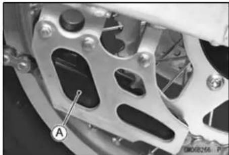
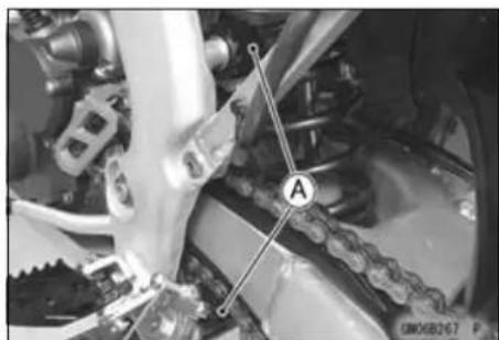
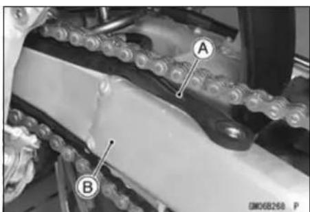
Tie-Rod, Rocker Arm
Tie-Rod Removal
- Using the jack under the frame, raise the rear wheel off the ground.
Special Tool - Jack: 57001-1238 - Unscrew the nut [A] and remove the guide roller [B].
NOTICE
When pulling out the mounting bolts, lift the rear wheel slightly. Forcing or tapping on a bolt could damage the bolt, sleeve, and bearing.
- Remove the tie-rod rear mounting bolt [A].
- Remove the tie-rod front mounting bolt [B], and then take out the tie-rod [C].
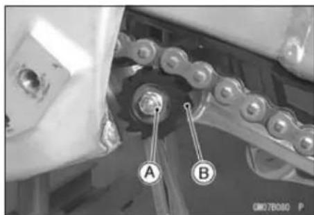
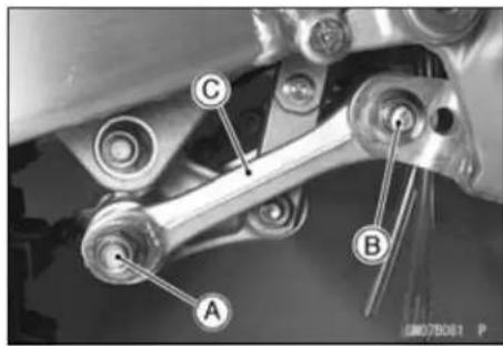
Tie-Rod Installation
- Apply plenty of grease to the inside of the oil seals.
- Apply plenty of 2-stroke oil to the threads of the tie-rod front and rear mounting bolts.
- Tighten the tie-rod front and rear mounting nuts.
Torque - Tie-Rod Mounting Nuts (Front, Rear): 59 N·m (6.0 kgf·m, 44 ft·lb)
Rocker Arm Removal
- Using the jack under the frame, raise the rear wheel off the ground.
Special Tool - Jack: 57001-1238
NOTICE
When pulling out the mounting bolts, lift the rear wheel slightly. Forcing or tapping on bolt could damage the bolt, sleeve, and bearing.
- Remove the rear shock absorber lower mounting bolt [A].
- Remove the tie-rod rear mounting bolt [B].
- Remove the rocker arm pivot bolt [C].
- Remove the rocker arm [D].

13-32 SUSPENSION
Tie-Rod, Rocker Arm
Rocker Arm Installation
- Apply plenty of grease to the inside of the rocker arm, needle bearings, oil seals and grease seals outside of the sleeve.
- Apply plenty of 2-stroke oil to the threads of the tie-rod rear mounting bolts.
- Tighten:
Torque - Rear Shock Absorber Mounting Nut (Lower): 34 N·m (3.5 kgf·m, 25 ft·lb)
Rocker Arm Pivot Nut: 59 N·m (6.0 kgf·m, 44 ft·lb)
Tie-Rod Mounting Nuts (Rear): 59 N·m (6.0 kgf·m, 44 ft·lb)
Tie-Rod and Rocker Arm Bearing Removal
- Remove:
Tie-Rod(see Tie-Rod Removal)
Rocker Arm (see Rocker Arm Removal)
Collars [A]
Sleeves [B]
Oil Seals [C]
Grease Seals [D]
- Remove the needle bearings [E], using the bearing remover head and bearing remover shaft.
- Remove the needle bearing [F], using the oil seal & bearing remover.
Special Tools - Bearing Remover Head: 57001-1267
Bearing Remover Shaft: 57001-1265
Oil Seal & Bearing Remover: 57001-1058
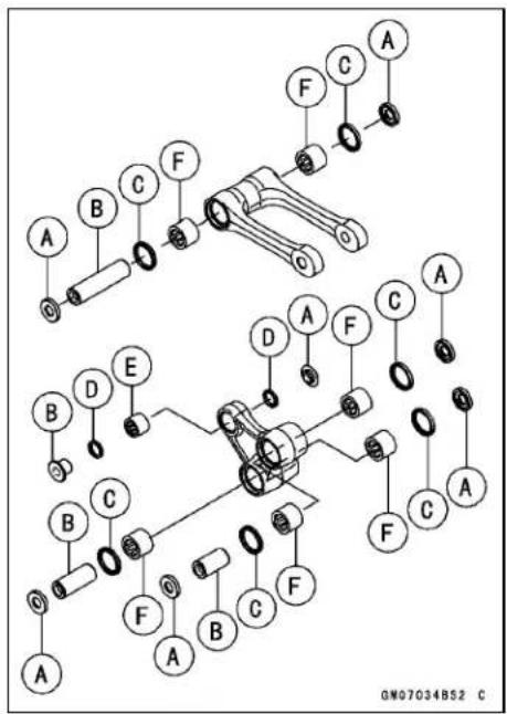
Tie-Rod, Rocker Arm
Tie-Rod and Rocker Arm Bearing Installation
- Replace the needle bearing, grease seals and oil seals with new ones.
- Apply plenty of grease to the oil seal and needle bearings [A].
NOTE
○ Install the grease seals so that the deep groove side of the rip out-ward.
- Install the needle bearings [A], [B] and grease seals [C] position as shown.
○Install the needle bearings and grease seals position as shown.
○The installation procedure is the same as the counter side.
1 mm (0.04 in.) [D] Rear Shock Absorber [G]
4.5 mm (0.18 in.) [E] Tie-rod [H]
4.25 mm (0.167 in.) [F] Rocker Arm [l]
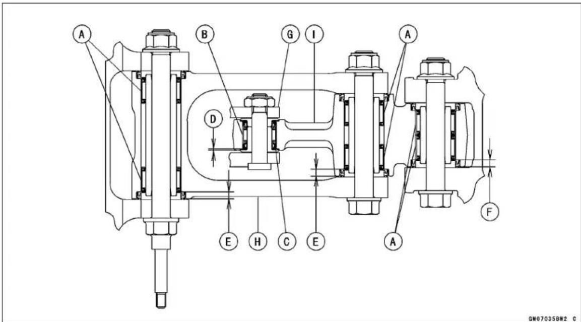
Needle Bearing Inspection
★If there is any doubt as to the condition of either needle bearing, replace the bearing and sleeve as a set.
13-34 SUSPENSION
Uni-Trak Maintenance
Uni-Trak Linkage Inspection
- Refer to the Swingarm and Uni-Trak Linkage Inspection in the Periodic Maintenance chapter.
Tie-Rod and Rocker Arm Sleeve Wear
- Pull out the sleeves [A] of the tie-rod and rocker arm.
● Measure the outside diameter of the sleeve.
★If the sleeve is worn past the service limit, replace the sleeve.
Sleeve Outside Diameter
Standard:
Tie-rod 19.987 \~ 20.000 mm (0.7888 \~ 0.78740 in.)
Rocker Arm:
[Large] 19.987 \~ 20.000 mm (0.78688 \~ 0.78740 in.)
[Small] 15.995 \~ 16.000 mm (0.62972 \~ 0.62992 in.)
Service Limit:
Tie-rod 19.85 mm (0.781 in.)
Rocker Arm:
[Large] 19.85 mm (0.781 in.)
[Small] 15.85 mm (0.624 in.)
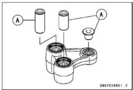
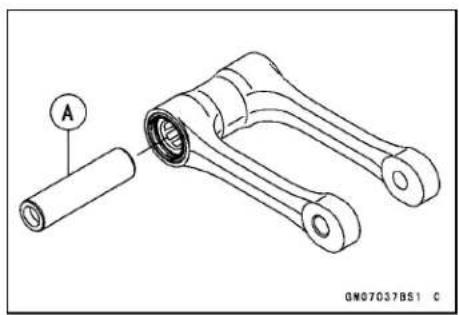
Tie-Rod and Rocker Arm Mounting Bolt Bend
A bent bolt causes vibration, poor handling, and instability.
- To measure the bolt runout, remove the bolt, place it in V blocks, and set a dial gauge to the bolt at a point halfway between the blocks. Turn [A] the bolt to measure the runout. The amount of dial variation is the amount of runout.
★If runout exceeds the service limit, replace the bolt.
Bolt Runout
Standard: Under 0.1 mm (0.004 in.)
Service Limit: 0.2 mm (0.008 in.)
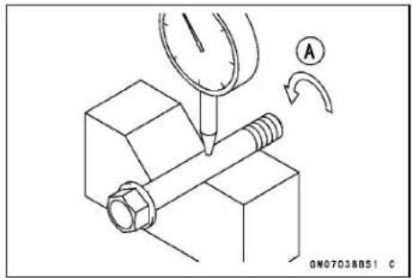
Steering
Table of Contents
Exploded View 14-2
Special Tools 14-4
Steering 14-5
Steering Inspection 14-5
Steering Adjustment.... 14-5
Steering Stem, Stem Bearing Removal 14-5
Steering Stem, Stem Bearing Installation 14-7
Stem Bearing Lubrication.... 14-8
Stem Bearing Wear, Damage 14-8
Stem Warp 14-8
Handlebar 14-9
Handlebar Removal 14-9
Handlebar Installation 14-9
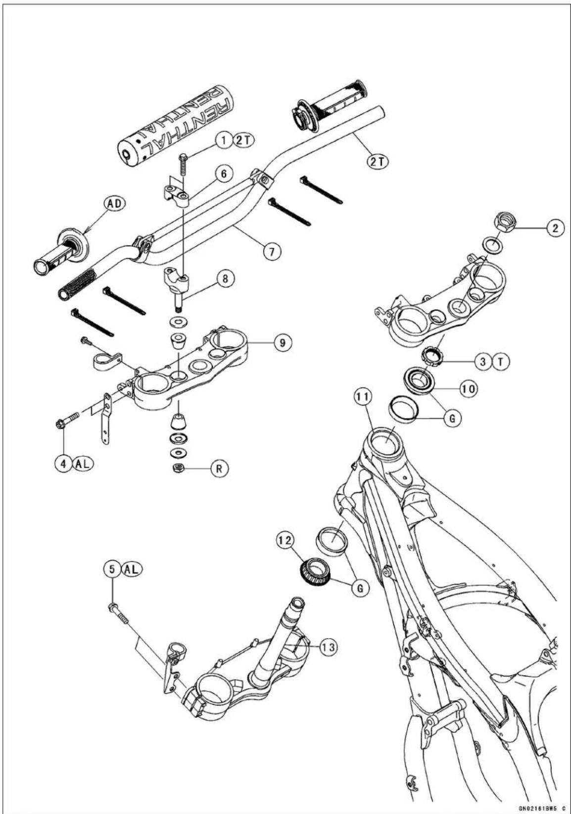
Exploded View
| No. | Fastener | Torque | Remarks | ||
| N·m kgf | m ft·lb | ||||
| 1 | Handlebar Clamp Bolts | 25 | 2.5 | 18 | 2T |
| 2 | Steering Stem Head Nut | 98 | 10 | 72 | |
| 3 | Steering Stem Nut | 4.9 | 0.50 | 43 in·lb | T |
| 4 | Front Fork Clamp Bolts (Upper) | 20 | 2.0 | 15 | AL |
| 5 | Front Fork Clamp Bolts (Lower) | 20 | 2.0 | 15 | AL |
- Handlebar Clamp
- Handlebar
- Handlebar Holder
- Steering Stem Head Bracket
- Upper Tapered Roller Bearing
- Head Pipe
- Lower Tapered Roller Bearing
- Steering Stem
AD: Apply adhesive cement.
AL: Tighten the two clamp bolts alternately two times to ensure even tightening torque.
G: Apply grease.
R: Replacement Parts
2T: Apply 2-stroke oil.
T: First, tighten the stem locknut with 39 N·m (4.0 kgf·m, 29 ft·lb) of torque, then loosen it and retighten it with 4.9 N·m (0.50 kgf·m, 43 in·lb) of torque.
14-4 STEERING
Special Tools
Bearing Puller: 57001-135
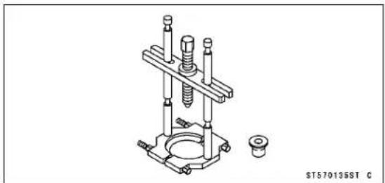
Steering Stem Bearing Driver: 57001-137
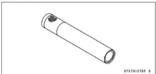
Steering Stem Bearing Driver Adapter, 34.5: 57001-1074
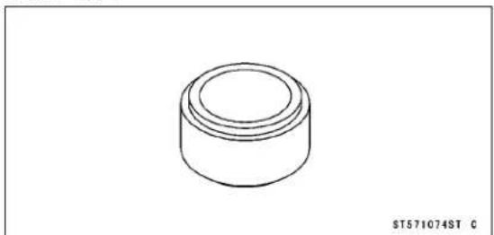
Head Pipe Outer Race Press Shaft: 57001-1075
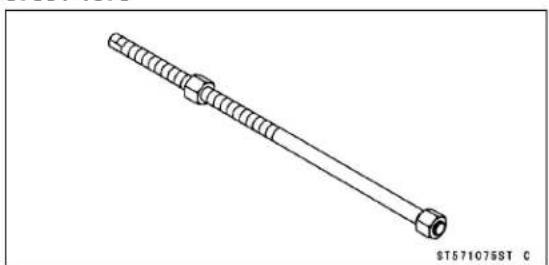
Head Pipe Outer Race Driver, 51.5: 57001-1076
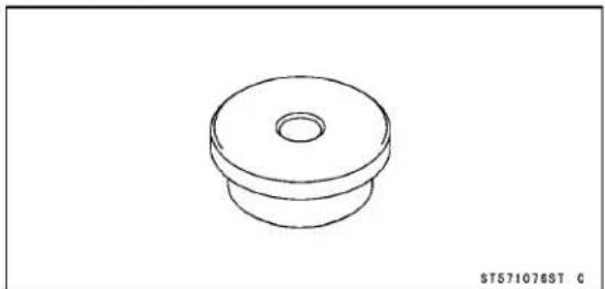
Head Pipe Outer Race Driver, 54.5: 57001-1077
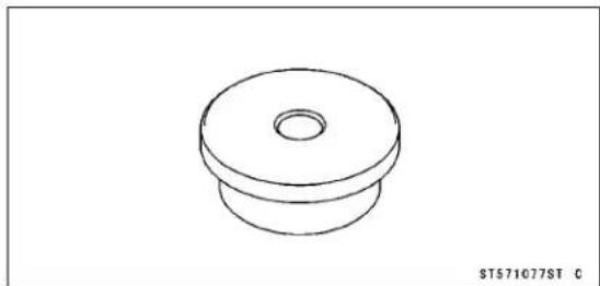
Steering Stem Nut Wrench: 57001-1100
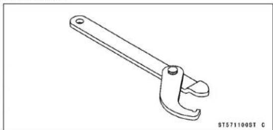
Head Pipe Outer Race Remover ID > 37 mm: 57001-1107
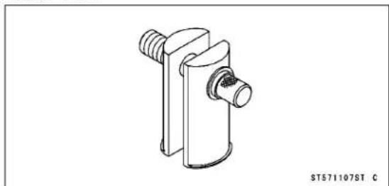
Jack: 57001-1238
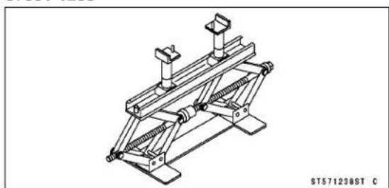
Bearing Puller: 57001-1575
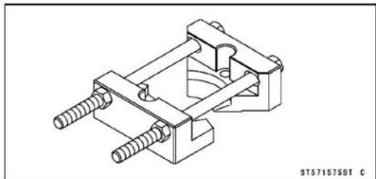
Steering
Steering Inspection
- Refer to the Steering Inspection in the Periodic Maintenance chapter.
Steering Adjustment
- Refer to the Steering Adjustment in the Periodic Maintenance chapter.
Steering Stem, Stem Bearing Removal
- Remove:
Front Wheel (see Front Wheel Removal in the Wheels/Tires chapter) Front Fender Bolts [A] Front Fender [B]
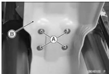
- Remove:
Handlebar Pad [A]
Headlight [B] (see Headlight Removal/Installation in the Electrical system chapter)
Speedometer [C] (see Meter Unit Removal/Installation in the Electrical System chapter)
Breather Hose [D] (Pull out)
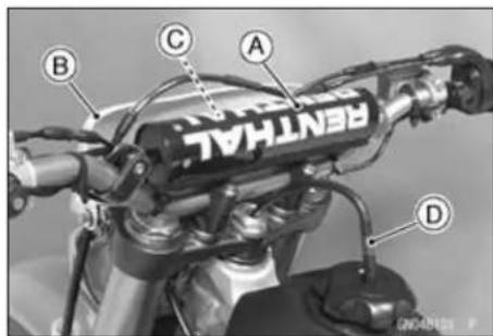
- Remove the bolt [A] to remove the brake hose [C] from the holder [B].
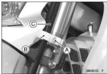
- Remove:
Handlebar Clamp Bolts [A]
Handlebar Clamps [B]
Handlebar [C] (see Handlebar Removal)
- Remove the front fork upper clamp bolts [D]
- Remove the steering stem head nut [E] and washer.
- Remove the steering stem head [F].
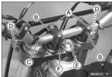
14-6 STEERING
Steering
- Remove: Front Fork Lower Clamp Bolts [A] Front Forks [B]
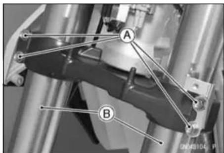
- Pushing up on the stem base [A], and remove the steering stem nut [B], with the steering stem nut wrench [C], then remove the steering stem [D] and stem base.
Special Tool - Steering Stem Nut Wrench: 57001-1100
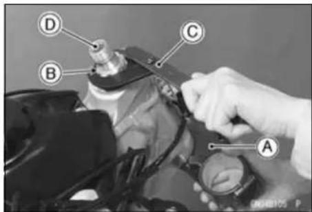
- Take off the upper stem bearing inner race (tapered roller bearing) [A].
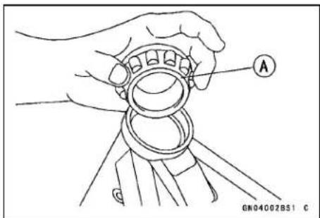
- Drive out the bearing outer races from the head pipe. ○Remove the outer races pressed into the head pipe, using the head pipe outer race remover [A], and hammer the head pipe outer race remover to drive it out.
Special Tool - Head Pipe Outer Race Remover ID > 37 mm: 57001-1107
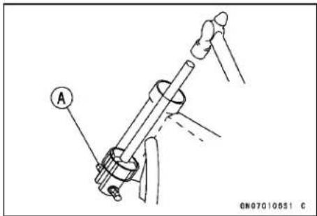
NOTE
○ If either steering stem bearing is damaged, it is recommended that both the upper and lower bearing (including outer races) should be replaced with new ones.
- Remove the lower stem bearing inner rase (tapered roller bearing) [A] with its grease seal from the stem using bearing puller.
Special Tools - Bearing Puller: 57001-1575
Bearing Puller: 57001-135
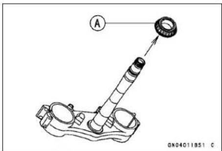
Steering
Steering Stem, Stem Bearing Installation
- Replace the bearing outer race with new ones.
○Apply grease to the outer races, and drive them into the head pipe at the same time using the head pipe outer race press shaft [A] and the head pipe outer race drivers.
Special Tools - Head Pipe Outer Race Press Shaft: 57001-1075
Head Pipe Outer Race Driver, φ54.5: 57001 -1077 [B]
Head Pipe Outer Race Driver, φ51.5: 57001-1076 [C]
- Replace the lower inner races with new ones.
○Apply grease to the lower tapered roller bearing [A], and drive it onto the stem using the steering stem bearing driver [B] and adapter [C].
Special Tools - Steering Stem Bearing Driver: 57001-137
Steering Stem Bearing Driver Adapter, φ 34.5:57001 - 1074
- Apply grease to the upper tapered roller bearing, and install it in the head pipe.
- Install the stem through the head pipe and upper bearing, install the stem cap and hand-tighten the stem nut while pushing up on the stem base.
- Install the stem head and washer, and tighten the stem head nut lightly.
- Settle the bearing in place as follows;
○ Tighten the stem nut to 39 N·m (4.0 kgf·m, 29 ft·lb) of torque. (To tighten the steering stem nut to the specified torque, hook the wrench [A] on the stem nut, and pull the wrench at the hole by 22.2 kg force [B] in the direction shown.)
Special Tool - Steering Stem Nut Wrench: 57001-1100
○Check that there is no play and the steering stem turns smoothly without rattles. If not, the steering stem bearings may be damaged.
○Again back out the stem nut a fraction of a turn until it turns lightly.
Turn the stem nut lightly clockwise until it just becomes hard to turn. Do not overtighten, or the steering will be too tight.
Torque - Steering Stem Nut: 4.9 N·m (0.50 kgf·m, 43 in·lb)
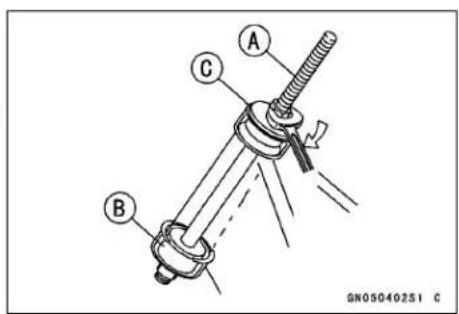

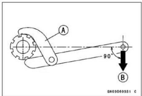
Steering
- Install the front fork (see Front Fork Installation in the Suspension chapter).
NOTE
○ Tighten the fork upper clamp bolts first, next the stem head nut, last the fork lower clamp bolt.
- Tighten:
Torque - Steering Stem Head Nut: 98 N·m (10 kgf·m, 72 ft·lb)
Front Fork Clamp Bolts (Upper): 20 N·m (2.0 kgf·m, 15 ft·lb)
Front Fork Clamp Bolts (Lower): 20 N·m (2.0 kgf·m, 15 ft·lb)
NOTE
○ Tighten the two clamp bolts alternately two times to ensure even tightening torque.
- Install the parts removed (see the appropriate chapter).
WARNING
If the handlebar does not turn to the steering stop it may cause an accident resulting in injury or death. Be sure the cables, harnesses and hoses are routed properly and do not interfere with handlebar movement (see Cable, Wire, and Hose Routing section in the Appendix chapter).
- Check and Adjust: Steering Front Brake Clutch Cable Throttle Cable
Stem Bearing Lubrication
- Refer to the Stem Bearing Lubrication in the Periodic Maintenance chapter.
Stem Bearing Wear, Damage
- Using a high-flash point solvent, wash the upper and lower tapered rollers in the cages, and wipe the upper and lower outer races, which are press-fitted into the frame head pipe, clean off grease and dirt.
- Visually check the outer rase and the rollers.
★Replace the bearing assembly if it show damage.
Stem Warp
- Whenever the steering stem is removed, or if the steering cannot be adjusted for smooth action, check the steering stem for straightness.
★If the steering stem shaft is bent [A], replace the steering stem.
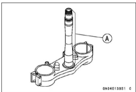
Handlebar
Handlebar Removal
- Remove:
Clutch Holder [A]
Engine Stop Switch [B]
Clamps [C]
Left Handlebar Grip [D]
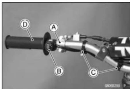
- Remove:
Throttle Grip Assy [A] (see Throttle Cable Replacement in the Fuel System chapter)
Master Cylinder [B] (see Front Master Cylinder Removal in the Brakes chapter)
Clamps [C]
Handlebar Pad [D]
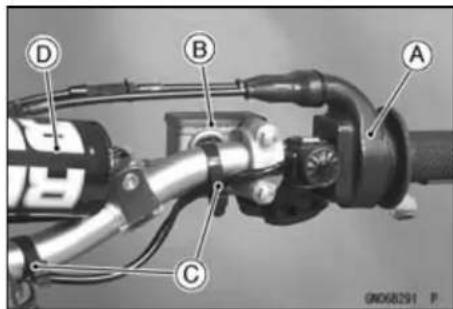
- Remove:
Handlebar Clamp Bolts [A]
Handlebar Clamps [B]
Handlebar [C]
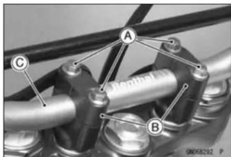
Handlebar Installation
- Apply adhesive cement to the inside of the left handlebar grip.
- Install the left handlebar grip so that the projection [A] on the grip face to the upward.
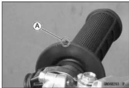
- Install the clutch lever [A] so that it incline 20° ± 5° [B] more than the horizontal line [C] and position it from the edge of the grip to 170 mm (6.69 in.) [D].
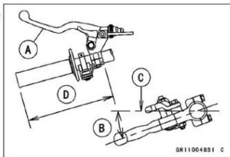
14-10 STEERING
Handlebar
- Apply grease to the throttle cable upper end and clutch cable upper end.
- Apply a 2-stroke oil to the throttle grip inner wall [A].
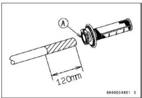
- Install the throttle grip assy so that the grip [A] is in as far as it will go.
- Position the throttle grip assy so that the parting line [B] of the throttle case vertically, and tighten the screws.
- Install the front master cylinder (see Front Master Cylinder Installation in the Brakes chapter).
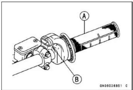
- Install the handlebar [B] on the handlebar holder so that the protruded scales of the both side adjust to the same width [A].
- Apply 2-stroke oil to the thread of the handlebar clamp bolts.
- Install the handlebar clamp so that center [D] of the handlebar clamp [C] and handlebar bridge [E] align.
Torque - Handlebar Clamp Bolts: 25 N·m (2.5 kgf·m, 18 ft·lb)
Front [F]
- After tighten, make sure space [A] [B] of the ahead and back are same width.
- Instal the clamps [C].
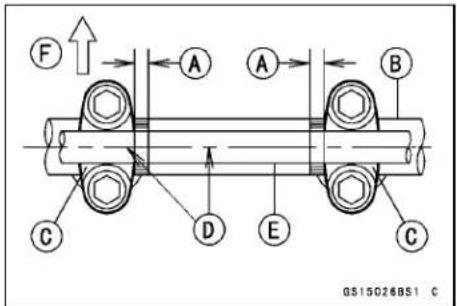
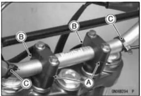
Frame
Table of Contents
Exploded View.... 15-2
Frame 15-5
Frame Inspection 15-5
Rear Frame Removal 15-5
Rear Frame Installation.... 15-5
Engine Guard Installation.... 15-6
Seat 15-7
Seat Removal 15-7
Seat Installation 15-7
Side Cover 15-8
Right Side Cover Removal.... 15-8
Right Side Cover Installation.... 15-8
Left Side Cover Removal 15-8
Left Side Cover Installation 15-9
Fender 15-10
Front Fender Removal 15-10
Rear Fender Removal.... 15-10
Rear Flap Removal 15-10
Reflector Installation 15-10
Footpegs and Brackets.... 15-11
Footpeg Removal.... 15-11
Footpegs Installation.... 15-11
15-2 FRAME
Exploded View
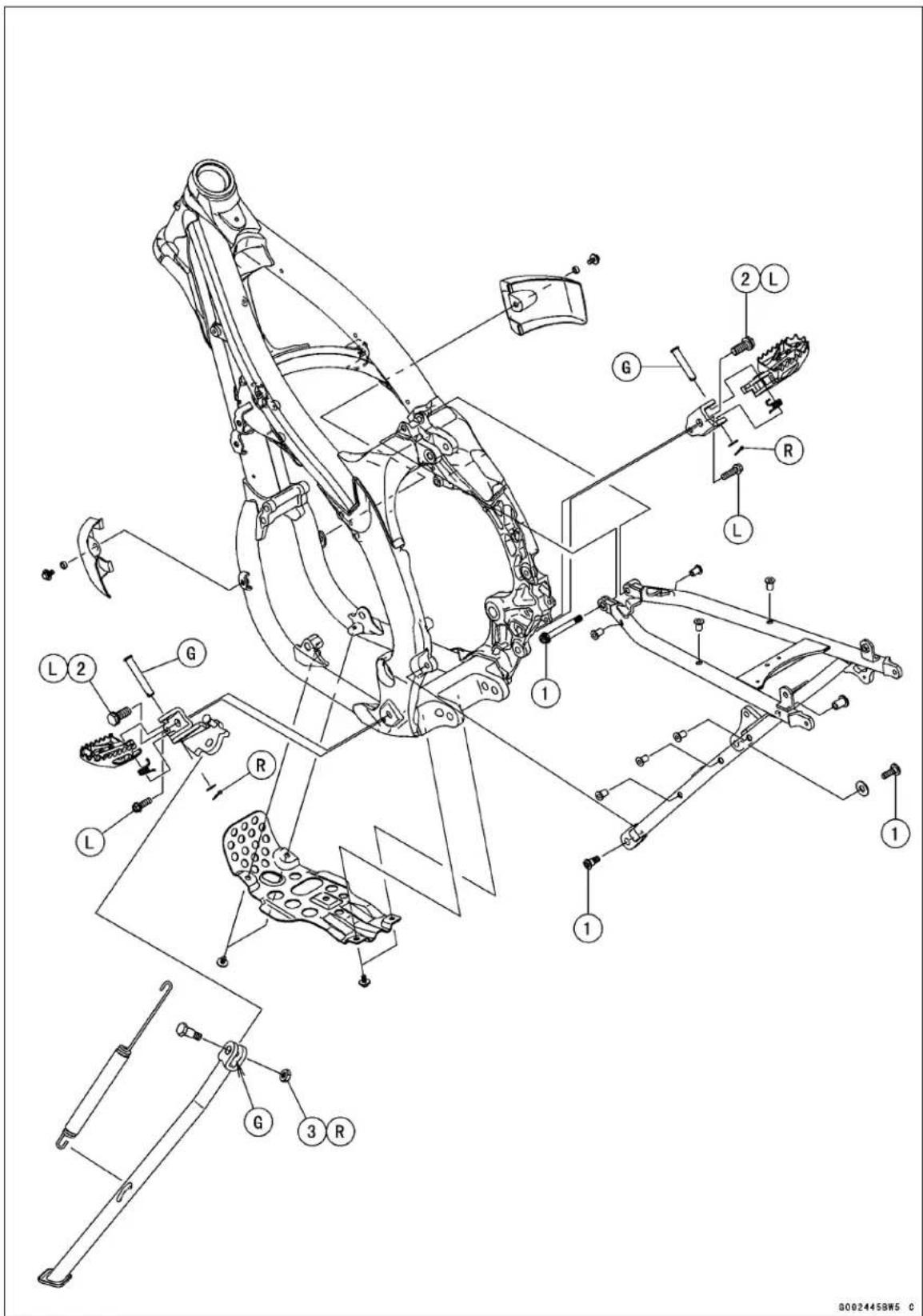
Exploded View
| No. | Fastener | Torque | Remarks | ||
| N·m | kgf·m ft | lb | |||
| 1 | Rear Frame Mounting Bolt | 34 | 3.5 | 25 | |
| 2 | Upper Footpeg Bracket Bolts | 54 | 5.5 | 40 | L |
| 3 | Sidestand Nut 29 3.0 21 R | ||||
G: Apply grease.
L: Apply a non-permanent locking agent.
R: Replacement Parts
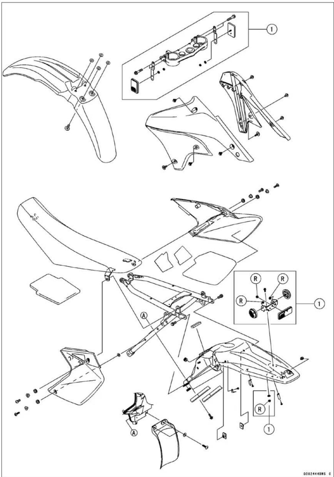
- CA Model
R: Replacement Parts
Frame
Frame Inspection
- Refer to the Frame Inspection in the Periodic Maintenance chapter.
Rear Frame Removal
- Remove:
Seat (see Seat Removal) Right and Left Side Cover (see Side Cover Removal) Battery Cables [A] and Holder [B] (see Battery Removal in the Electrical System chapter) Starter Motor Cable [C] Starter Relay Connector [D] Starter Relay [E] Main Relay [F] Tail Light Lead Connector [G] Igniter [H] Reserve Tank (see Reserve Tank Removal in the Cooling System chapter) Muffler (see Muffler Removal in the Engine Top End chapter) Rear Fender (see Rear Fender Removal)
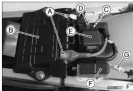
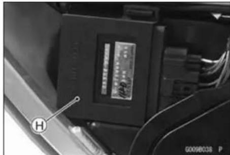
- Loosen the air cleaner duct clamp screw (see Air Cleaner Housing Removal in the Fuel System chapter).
- Unscrew the rear frame mounting bolts [A].
- Remove the rear frame [B] with air cleaner housing [C].
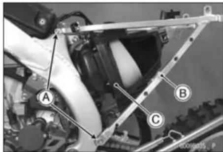
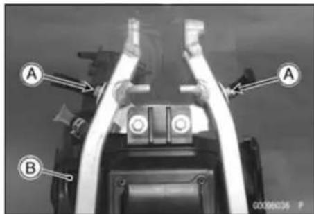
- Remove:
Bolts [A] Air Cleaner Housing [B]
Rear Frame Installation
• Install the air cleaner housing.
- Tighten:
Torque - Rear Frame Mounting Bolts: 34 N·m (3.5 kgf·m, 25 ft·lb)
• Install the removal parts.
15-6 FRAME
Frame
Engine Guard Installation
• Install the engine guard as shown.
Engine Guards [A]
Collar [B]
Bolts [C]
Engine Guard [D]
Bolts [E]
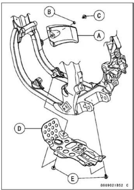
Seat
Seat Removal
- Remove the bolts [A].
- Pull the seat [B] out from the back.
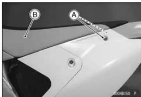
Seat Installation
- Stick the pad on the inside of the seat.
- Fit the hooks [A] of the seat under the flange collar [B] and brackets [C].
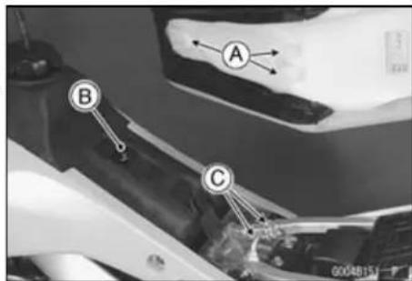
○Install the brackets [A] of the seat to inside [B] of side cover.
- Tighten the seat mounting bolts.
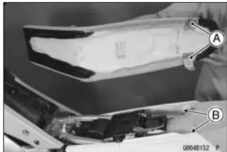
15-8 FRAME
Side Cover
Right Side Cover Removal
- Remove: Bolts [A] Side Cover [B]
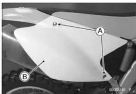
Right Side Cover Installation
- Stick the pad [A] on the inside of the right side cover [B].
- Insert the inside rib [C] between rear fender and rear frame.
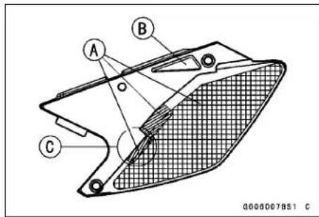
- Insert the tab [A] of the right side cover into the air cleaner housing [B], and install the bolts.
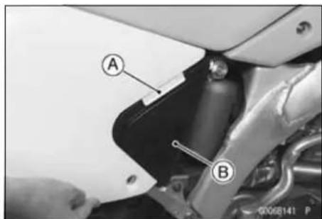
Left Side Cover Removal
- Remove: Air Cleaner Cover [A] Quick Fastener [B]
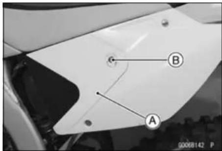
- Remove: Bolts [A] Washer [B] Left Side Cover [C]
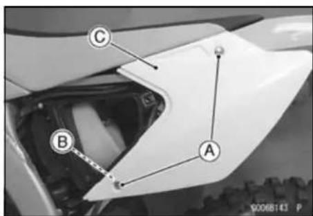
Side Cover
Left Side Cover Installation
- Install:
Left Side Cover
Washer
Bolts
Air Cleaner Cover [A]
Quick Fastener
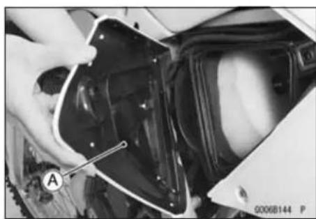
Fender
Front Fender Removal
- Unscrew the bolts [A] and remove the front fender [B].
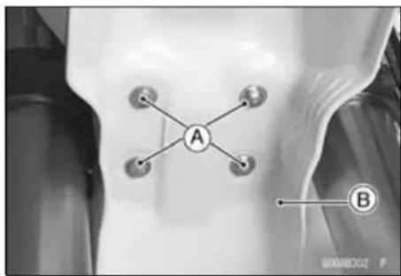
Rear Fender Removal
- Remove:
Seat (see Seat Removal)
Reserve Tank (see Reserve Tank Removal in the Cooling System chapter)
Regulator/Rectifier (see Regulator/Rectifier Inspection in the Electrical System chapter)
- Unscrew the bolts [A] and remove the rear fender [B].
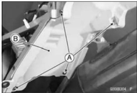
Rear Flap Removal
● Unscrew the screws [A] and remove the rear flap [B].
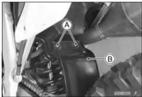
Reflector Installation
- Install the reflector so that the projection [A] fits to the groove [B] of the bracket.
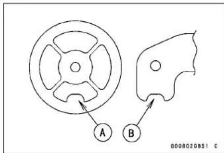
Footpegs and Brackets
Footpeg Removal
- Remove:
Cotter Pin [A]
Washer [B]
Pin [C]
Spring [D]
Footpeg [E]
Upper Bolt [F]
Lower Bolt [G]
Footpeg Bracket [H]
Footpegs Installation
- Apply a non-permanent locking agent to the bracket lower bolts.
- Tighten the upper bracket bolt [A].
Torque - Upper Footpeg Bracket Bolts: 54 N·m (5.5 kgf·m, 40 ft·lb)
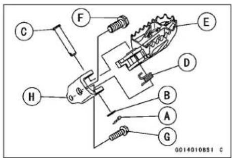
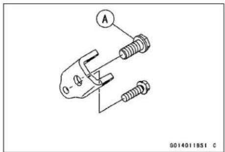
- Install:
Footpeg [A]
Cotter Pin [B]
- Bend the longer side [C] of the cotter pin as shown.
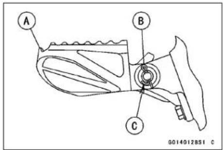
Electrical System
Table of Contents
Exploded View.... 16-2
Specifications 16-8
Special Tools and Sealant.... 16-9
Wiring Diagram (Other than Australia
Models).... 16-11
Precautions.... 16-12
Electrical Wiring.... 16-13
Wiring Inspection 16-13
Battery 16-14
Battery Removal 16-14
Battery Installation 16-14
Precautions.... 16-14
Interchange.... 16-15
Charging Condition Inspection..... 16-15
Refreshing Charge.... 16-16
Flywheel Magneto 16-17
Magneto Cover Removal...... 16-17
Magneto Cover Installation 16-18
Flywheel Removal.... 16-18
Flywheel Installation.... 16-19
Stator Removal 16-20
Stator Installation.... 16-20
Flywheel Inspection 16-20
Charging Voltage Inspection...... 16-22
Regulator/Rectifier Inspection..... 16-22
Starter Motor Clutch 16-24
Starter Motor Clutch Removal/Installation.... 16-24
Starter Motor Clutch Inspection ... 16-24
Starter Motor Clutch Disassembly 16-24
Starter Motor Clutch Assembly.... 16-24
Ignition Timing 16-25
Ignition Timing Inspection 16-25
Ignition System.... 16-26
Crankshaft Sensor Removal..... 16-26
Crankshaft Sensor Installation..... 16-26
Safety Instructions 16-26
Ignition Coil Removal.... 16-26
Ignition Coil Inspection...... 16-27
Spark Plug Cleaning and Inspection.... 16-27
Spark Plug Gap Inspection 16-28
Igniter Removal.... 16-28
Igniter Inspection.... 16-28
Throttle Position Sensor Resistance Inspection...... 16-33
Throttle Position Sensor Position
Adjustment 16-34
Crankshaft Sensor Inspection..... 16-34
Electrical Starter System 16-36
Starter Motor Removal...... 16-36
Starter Motor Installation...... 16-36
Starter Motor Disassembly...... 16-36
Starter Motor Assembly 16-37
Carbon Brush Inspection 16-37
Commutator Inspection, Cleaning 16-38
Armature Inspection.... 16-38
Brush Lead Inspection 16-38
Terminal Bolt Inspection...... 16-39
Starter Relay Inspection...... 16-39
Lighting System.... 16-41
Headlight Aiming Inspection ..... 16-41
Headlight Beam Vertical Adjustment 16-41
Headlight Bulb Replacement ..... 16-41
Headlight Removal/Installation .... 16-42
Tail Light Removal.... 16-43
Tail Light Installation.... 16-43
Meter Gauge.... 16-45
Meter Unit Removal/Installation... 16-45
Meter Unit Disassembly/Assembly.... 16-45
Switch Inspection.... 16-45
LCD Segment Inspection...... 16-47
Switches and Sensors.... 16-49
Speed Sensor Removal.... 16-49
Speed Sensor Installation...... 16-49
Speed Sensor Inspection...... 16-49
Throttle Position Sensor Removal/Installation.... 16-50
Switch Inspection.... 16-50
Gear Position Switch Removal .... 16-50
Gear Position Switch Installation . 16-51
Gear Position Switch Inspection.. 16-52
Main Relay.... 16-53
Main Relay Inspection.... 16-53
Fuses.... 16-54
Main Fuse 20 A Removal...... 16-54
Main Fuse 20 A Inspection ..... 16-54
Exploded View
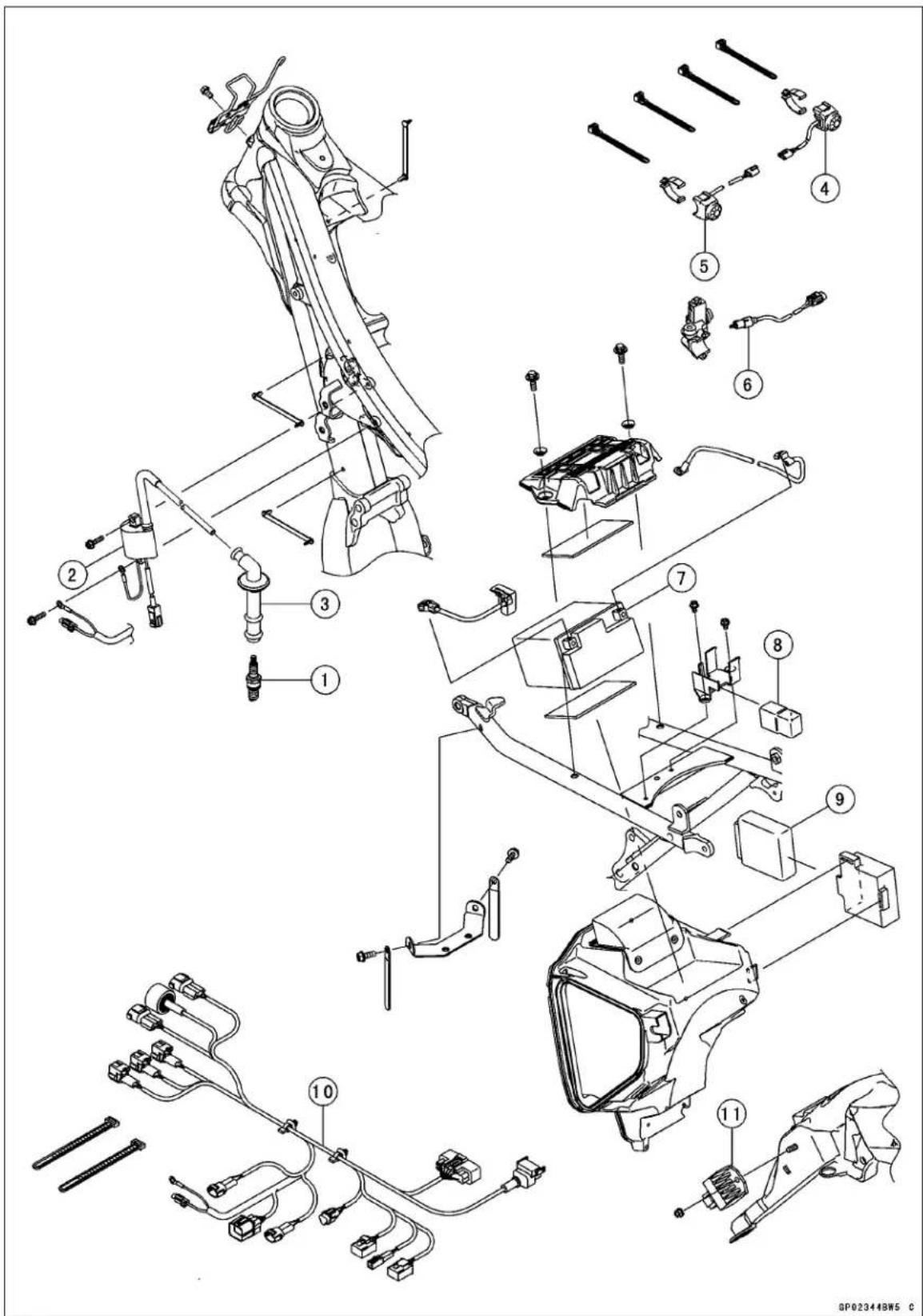
Exploded View
| No. | Fastener | Torque | Remarks | ||
| N·m kgf | m ft·lb | ||||
| 1 | Spark Plug | 13 | 1.3 | 115 in·lb | |
- Ignition Coil
- Spark Plug Cap
- Starter Button
- Engine Stop Switch
- Starter Lockout Switch
- Battery
- Main Relay
- Igniter
- Main Harness
- Regulator/Rectifier
Exploded View
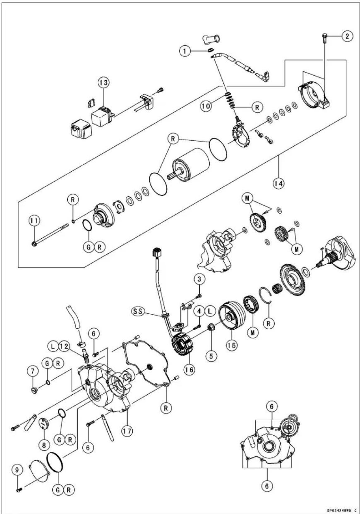
Exploded View
| No. | Fastener | Torque | Remarks | ||
| N·m kgf | m ft·lb | ||||
| 1 | Starter Motor Terminal Nut | 5.9 | 0.60 | 52 in·lb | |
| 2 | Starter Motor Mounting Bolts | 9.8 | 1.0 | 87 in·lb | |
| 3 | Crankshaft Sensor Bolts | 7.0 | 0.71 | 62 in·lb | |
| 4 | Stator Bolts | 4.0 | 0.41 | 35 in·lb | L |
| 5 | Flywheel Nut | 98 | 10 | 72 | |
| 6 | Magneto Cover Bolts | 9.8 | 1.0 | 87 in·lb | |
| 7 | Timing Inspection Cap | - | - | - | Hand-Tighten |
| 8 | Flywheel Nut Cap | - | - | - | Hand-Tighten |
| 9 | Torque Limiter Cover Bolts | 9.8 | 1.0 | 87 in·lb | |
| 10 | Starter Motor Terminal Locknut | 6.9 | 0.70 | 61 in·lb | |
| 11 | Starter Motor Through Bolts | 3.4 | 0.35 | 30 in·lb | |
| 12 | Breather Fitting | 15 | 1.5 | 11 | L |
- Starter Relay
- Starter Motor
- Magneto
- Stator
- Magneto Cover
G: Apply grease.
L: Apply a non-permanent locking agent.
M: Apply molybdenum dislfide grease.
R: Replacement Parts
SS: Apply silicone sealant.
Exploded View
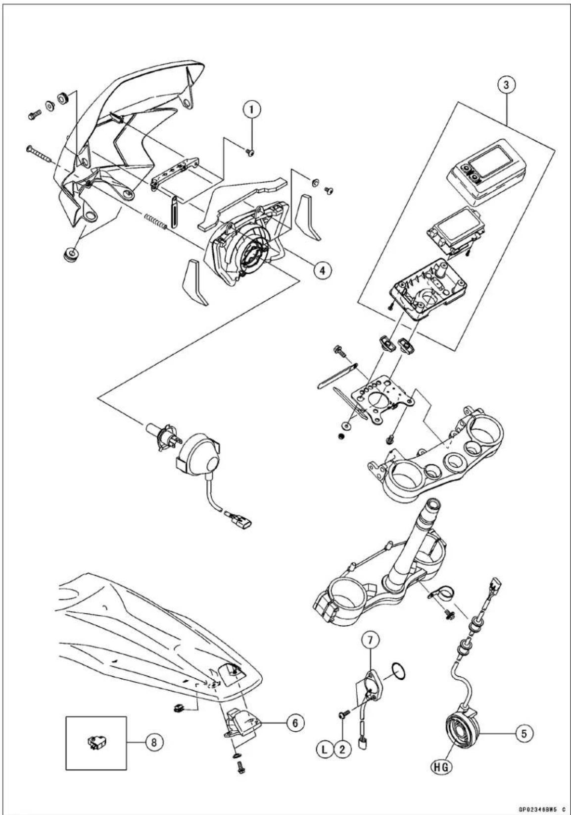
Exploded View
| No. | Fastener | Torque | Remarks | ||
| N·m kgf | m ft·lb | ||||
| 1 | Head Light Bracket Screws | 1.4 | 0.14 | 12 in·lb | |
| 2 | Gear Position Switch Screws | 2.9 | 0.30 | 26 in·lb | L |
- Meter Unit
- Headlight
- Speed Sensor
- Tail Light
- Gear Position Switch
- Australia Models
HG: Apply high-temprerature grease.
L: Apply a non-permanent locking agent.
Specifications
| Item Standard Service Limit | ||
| BatteryType Sealed Battery (wet) -- -Model YTZ7S (F) -- -Capacity 12 V 6 Ah -- - | ||
| MagnetoCrankshaft Sensor Resistance Magneto Output Voltage Stator Coil Resistance | 190 ~ 290 Ω (at 20°C (68°F)) in the text in the text | -- -- -- -- -- |
| Ignition SystemIgnition Timing Ignition Coil:3 Needle Arcing Distance Primary Winding Resistance Secondary Winding Resistance Spark Plug:Type Gap IC Igniter | 10.2° BTDC @1 000 r/min (rpm)7 mm (0.26 in.) or more0.28 ~ 0.38 Ω (at 20°C (68°F))7.65 ~ 10.35 kΩ (at 20°C (68°F))NGK CPR8EB-90.8 ~ 0.9 mm (0.03 ~ 0.04 in.)in the text | -- -- -- -- -- -- -- -- -- -- -- -- -- -- -- -- -- -- -- -- -- -- -- -- -- -- -- -- -- -- -- -- -- -- -- -- -- -- -- -- -- -- -- -- -- -- -- -- -- -- -- -- -- -- -- -- -- -- -- -- -- -- -- -- -- -- -- -- -- -- -- -- -- -- -- -- -- -- -- -- -- -- -- -- -- -- -- -- -- -- -- -- -- -- -- -- -- -- -- -- -- |
| Electric Starter SystemStarter Motor:Brush Length Commutator Diameter | 10 mm (0.39 in.)28 mm (1.10 in.) | 6.5 mm (0.26 in.)27 mm (1.06 in.) |
| Throttle position sensorInput Voltage Output Voltage:when engine is idle speed | around 5 V0.58 ~ 0.78 V | -- -- -- -- -- -- -- -- -- -- -- -- -- -- -- -- -- -- -- -- -- -- -- -- -- -- -- -- -- -- -- -- -- -- -- -- -- -- -- -- -- -- -- -- -- -- -- -- -- -- -- -- -- -- -- -- -- -- -- -- -- -- -- -- -- -- -- -- -- -- -- -- -- -- -- -- -- -- -- -- -- -- -- -- -- -- -- -- -- -- -- -- -- -- -- -- -- -- |
Special Tools and Sealant
Inside Circlip Pliers: 57001-143
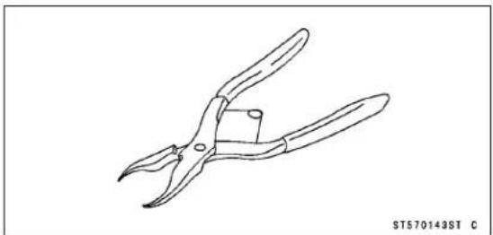
Rotor Puller, M16/M18/M20/M22 × 1.5: 57001-1216
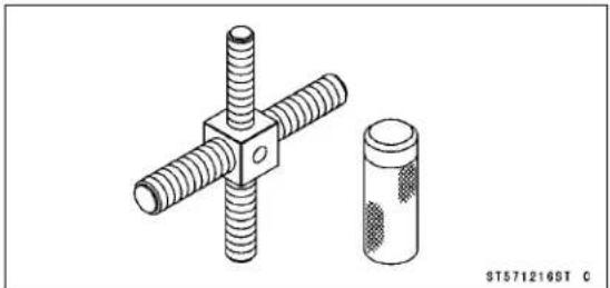
Timing Light: 57001-1241
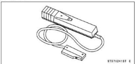
Spark Plug Wrench, Hex 16: 57001-1262
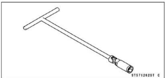
Flywheel Holder: 57001-1313
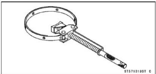
Hand Tester: 57001-1394
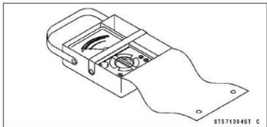
Throttle position sensor Setting Adapter #1: 57001-1400
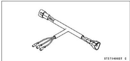
Peak Voltage Adapter: 57001-1415
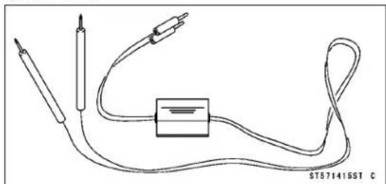
Filler Cap Driver: 57001-1454
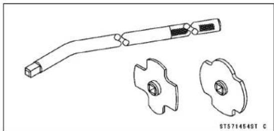
Needle Adapter Set: 57001-1457
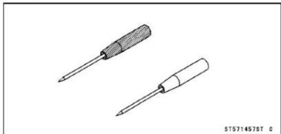
16-10 ELECTRICAL SYSTEM
Special Tools and Sealant
Flywheel Puller, M28 × 1.0: 57001-1471
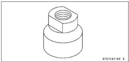
Liquid Gasket, TB1211F: 92104-0004
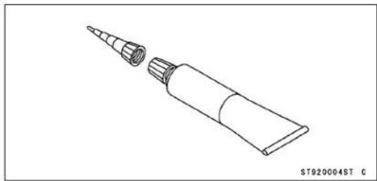
Wiring Diagram (Other than Australia Models)
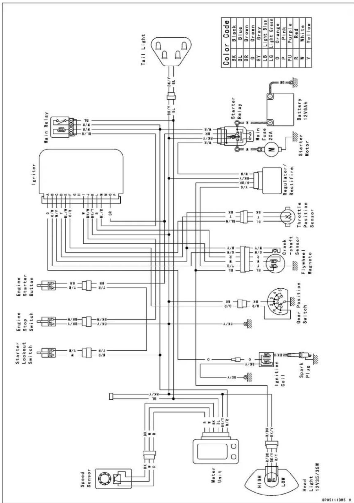
16-12 ELECTRICAL SYSTEM
Precautions
There are numbers of important precautions that are musts when servicing electrical systems. Learn and observe all the rules below.
The electrical parts should never be struck sharply, as with a hammer, or allowed to fall on a hard surface. Such a shock to the parts can damage them.
○Troubles may involve one or in some cases all items. Never replace a defective part without determining what CAUSED the failure. If the failure was caused by some other item or items, they too must be repaired or replaced, or the new replacement will soon fail again.
○Make sure all connectors in the circuit are clean and tight, and examine wires for signs of burning, fraying, etc. Poor wires and bad connections will affect electrical system operation.
○Measure coil and winding resistance when the part is cold (at room temperature).
Electrical Connectors
[A] Connectors
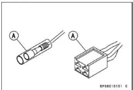
[B] Connectors
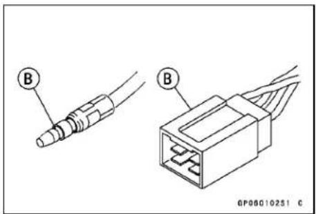
Safety Instructions:
WARNING
The ignition system produces extremely high voltage. Do not touch the spark plug, ignition coil or high tension lead while the engine is running, or you could receive a severe electrical shock.
Electrical Wiring
Wiring Inspection
- Visually inspect the wiring for signs of burning, fraying, etc.
★If any wiring is poor, replace the damaged wiring. - Pull each connector [A] apart and inspect it for corrosion, dirt, and damage.
★If the connector is corroded or dirty, clean it carefully. If it is damaged, replace it. - Check the wiring for continuity.
○Use the wiring diagram to find the ends of the lead which is suspected of being a problem.
○Connect an ohmmeter between the ends of the leads.
○Set the meter to the x 1 Ω range, and lead the meter.
★If the meter does not read 0 Ω the lead is defective. Replace the lead or the wiring harness if necessary.
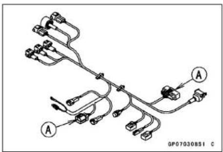
- Remove the seat (see Seat Removal in the Frame chapter).
- Disconnect the negative (−) cable [A] and then positive (+) cable [B].
NOTICE
Be sure to disconnect the negative (−) cable first.
- Remove the battery holder bolts [C] and holder [D].
- Remove the battery.
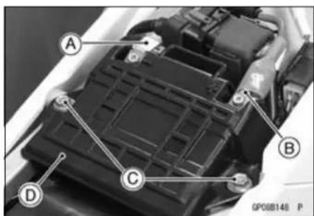
Battery Installation
- Visually inspect the surface of the battery container.
★If any signs of cracking or electrolyte leakage from the sides of the battery. - Put the battery into the battery case.
• Install the battery holder and tighten the bolts. - Connect the positive cable [A] to the (+) terminal first, and then the negative cable [B] to the (−) terminal.
- Apply a light coat of grease on the terminals to prevent corrosion.
- Cover the (+) terminal with the cap.
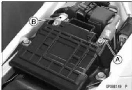
Precautions
1) No need of topping-up No topping-up is necessary in this battery until it ends its life under normal use. Forcibly prying off the seal cap to add water is very dangerous. Never do that.
2) Refreshing charge.
Give refresh charge for 5 to 10 hours with charge current shown in the specification (see Refreshing Change).
When a fast charge is inevitably required, do it following precisely the maximum charge current and time conditions indicated on the battery.
NOTICE
This battery is designed to sustain no unusual deterioration if refresh-charged according to the method specified above. However, the battery's performance may be reduced noticeably if charged under conditions other than given above. Never remove the seal cap during refresh charge.
If by chance an excessive amount of gas is generated due to overcharging, the relief valve releases the gas to keep the battery normal.
3) When you do not use the motorcycle for months.
Give a refresh charge before you store the motorcycle and store it with the negative cable removed. However, check the battery's state of charge at every 6 months to be sure it meets the minimum 12.4 V specification and charge it to 100 % state of charge.
4) Battery life.
If the battery will not start the engine even after several refresh charges, the battery has exceeded its useful life. Replace it (Provided, however, the vehicle's starting system has no problem).
Battery
DANGER
Batteries produce an explosive gas mixture of hydrogen and oxygen that can cause serious injury and burns if ignited. Keep the battery away from sparks and open flames during charging. When using a battery charger, connect the battery to the charger before turning on the charger. This procedure prevents sparks at the battery terminals which could ignite any battery gases. The electrolyte contains sulfuric acid. Be careful not to have it touch your skin or eyes. If touched, wash it off with liberal amount of water and seek medial attention for more severe burns.
Interchange
A sealed battery can fully display its performance only when combined with a proper vehicle electric system. Therefore, replace a sealed battery only on a motorcycle which was originally equipped with a sealed battery.
Be careful, if a sealed battery is installed on a motorcycle which had an ordinary battery as original equipment, the sealed battery's life will be shortened.
Battery Date Inspection
- Remove the battery (see Battery Removal).
- Check the manufactured date stamp [A].
Day [B]
Month [C]
Year [D]
MFG Code [F]
NOTE
○ Do refresh charge with the battery that passes one month or more.
Charging Condition Inspection
○Battery charging condition can be checked by measuring battery terminal voltage with a digital voltmeter [A].
- Remove the seat (see Seat Removal in the Frame chapter).
- Disconnect the battery terminals.
NOTICE
Be sure to disconnect the negative (−) cable first.
- Measure the battery terminal voltage.
NOTE
○Measure with a digital voltmeter which can be read one decimal place voltage.
★If the reading is 12.4 V or more, refresh charge is not required, however, if the read is below the 12.4 V, refresh charge is required.
Terminal Voltage (V) [A]
Battery Charge Rate (%) [B]
Refresh charge is required [C]
Good [D]
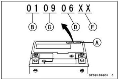
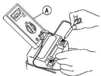
GP08010851 C
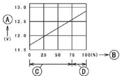
GP08071BSI C
Battery
Refreshing Charge
- Remove the battery (see Battery Removal).
- Do refresh charge by following method according to the battery terminal voltage.
WARNING
This battery is sealed type. Charge with current and time as stated below.
Terminal Voltage: 12 \~ less than 12.4 V
Standard Charge 0.6 A × 5 \~ 10 h (see following chart)
Quick Charge 3 A × 1 h
NOTICE
If possible, do not quick charge. If quick charge is done unavoidably, do standard charge later on.
Terminal Voltage: less than 12 V
Charging Method: 0.6 A × 20 h
NOTE
○ Increase the charging voltage to a maximum voltage of 25 V if the battery will not accept current initially. Charge for no more than 5 minutes at the increased voltage then check if the battery is drawing current. If the battery will accept current decrease the voltage and charge by the standard charging method described on the battery case. If the battery will not accept current after 5 minutes, replace the battery.
Battery [A]
Battery Charger [B]
Standard Value [C]
Current starts to flow [D].
- Determine the battery condition after refresh charge.
- Determine the condition of the battery left for 30 minutes after completion of the charge by measuring the terminal voltage according to the table below.
| Criteria | Judgement |
| 12.8 V or higher | Good |
| 12.0 ~ lower than 12.8 V | Charge insufficient → Recharge |
| lower than 12.0 V | Unserviceable → Replace |
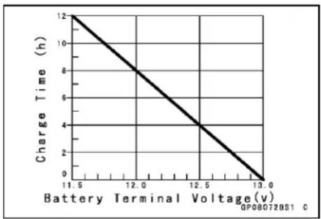
![graph TD A["Measurement System"] --> B["V-A"] B --> C["Capacitor A"] B --> D["Capacitor B"] D --> E["Ground"] F["Input Signal"] --> G["2.5 V, 16 A"] H["Ground"] --> I["Ground"]](/content/2026/05/818283/images/26a62d4683dffb4a3332a6c55da664a2e5f03723fb23254308738411a481849f.jpg)
Flywheel Magneto
Magneto Cover Removal
- Remove:
Left Radiator Shroud
Bolt [A]
Left Radiator Screen [B]
Left Radiator Mounting Bolts [C]
- Push the left radiator backward [D].
- Pry open the clamps [A].
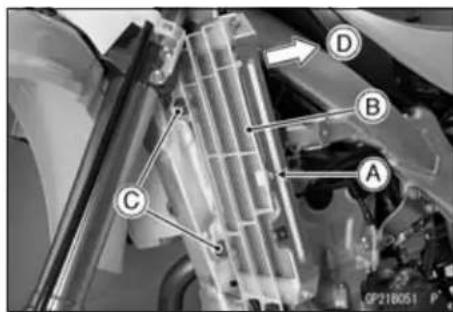
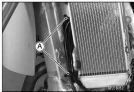
- Drain the engine oil from the crank room oil sump (see Engine Oil Change in the Periodic Maintenance chapter).
- Pull the stopper [A] to the this side to remove the magneto lead connector [B].
- Disconnect the magneto lead connector from the main harness.
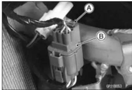
- Remove:
Torque Limiter [A] (see Torque Limiter Removal/Installation in the Crankshaft/Transmission chapter)
Bolt [B]
Left Engine Guard [C]
Breather Hose [D]
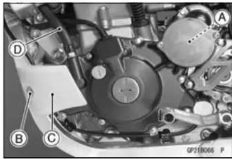
- Remove the shift pedal (see External Shift Mechanism Removal in the Engine Right Side chapter).
- Remove:
Magneto Cover Mounting Bolts [A].
Magneto Cover [B]
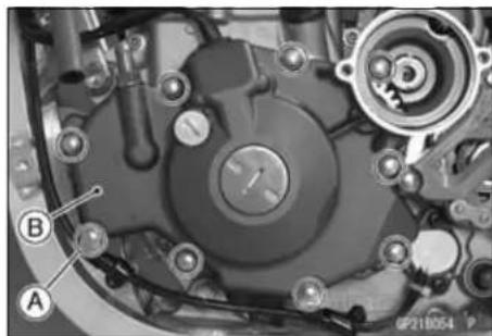
16-18 ELECTRICAL SYSTEM
Flywheel Magneto
Magneto Cover Installation
- Replace the gasket [A] with a new one.
- Be sure to install the dowel pins [B].
- Apply silicone sealant to the area [A] to the magneto lead grommet.
Sealant - Liquid Gasket, TB1211F: 92104-0004
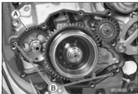
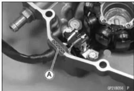
- Tighten: Torque - Magneto Cover Bolts: 9.8 N·m (1.0 kgf·m, 87 in·lb)
- Run the gear position switch lead [A] and magneto lead according the Cable, Wire, and Hose Routing section in the Appendix chapter. Clamps [B]
- Connect the lead connector.
• Install the removed parts.
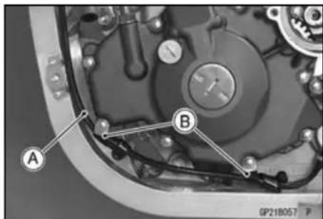
Flywheel Removal
- Remove the magneto cover (see Magneto Cover Removal).
- Hold the flywheel steady, with the flywheel holder [A], and remove the nut [B].
Special Tool - Flywheel Holder: 57001-1313
- Remove the flywheel holder.
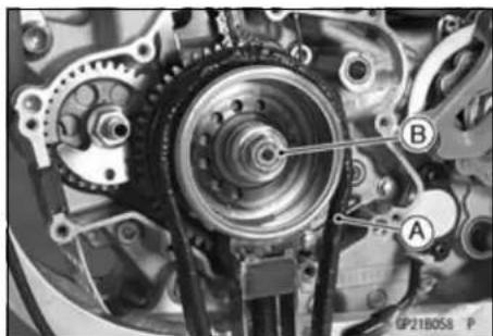
Flywheel Magneto
- Screw the rotor pullers [A] onto the flywheel.
- Remove the flywheel from the crankshaft by turning in the puller and tapping the head of the bolt lightly with a hammer, while holding the puller body steady. There is a woodruff key in the crankshaft tapered portion.
Special Tools - Flywheel Rotor Puller: 57001-1471 Rotor Puller, M16/M18/M20/M22 × 1.5: 57001-1216
NOTICE
If the flywheel is difficult to remove, turn the puller shaft using a wrench while tapping the head of the puller shaft with a hammer. Do not attempt to strike the grab bar or the flywheel itself. Striking the bar or the flywheel can cause the bar to bend or the magnets to lose their magnetism.
Flywheel Installation
- Using a high-flash point solvent, clean off any oil or dirt that may be on the crankshaft taper [A] or in the hole [B] in the flywheel. Dry them with a clean cloth.
- Fit the woodruff key [C] securely in the slot in the crankshaft.
• Install the flywheel following procedures.
NOTE
○ Confirm the flywheel fit or not to the crankshaft before tightening it with specified torque.
○Install the flywheel and tighten it with 54 N·m (5.5 kgf·m, 40 ft·lb) of torque.
○Remove the flywheel nut.
○Check the tightening torque with rotor puller.
★If the flywheel is not pulled out with 20 N·m (2 kgf·m, 15 ft·lb) of drawing torque, it is installed correctly.
★If the flywheel is pulled out with under 20 N·m (2 kgf·m, 15 ft·lb) of drawing torque, clean off any oil dirt or flaw of the crankshaft and flywheel tapered portion, and dry them with a clean cloth. Then, confirm that it is not pulled out with above torque.
- Holding the flywheel steady, with the flywheel holder, and tighten the flywheel nut.
Special Tool - Flywheel Holder: 57001-1313
Torque - Flywheel Nut: 98 N·m (10 kgf·m, 72 ft·lb)
- Install the magneto cover (see Magneto Cover Installation).
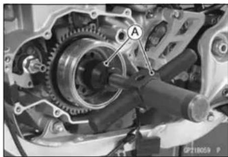

Flywheel Magneto
Stator Removal
- Remove:
Magneto Cover (see Magneto Cover Removal)
Stator Bolts [A]
Crankshaft Sensor Bolts [B]
Wiring Holder [C]
Wiring Grommet [D]
- Remove the stator [E] and crankshaft sensor [F] as a set.
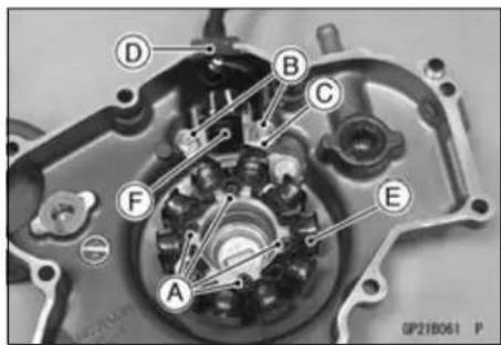
Stator Installation
- Route the wires according to the Cable, Wire, and Hose Routing section in the Appendix chapter.
- Apply a non-permanet locking agent to the stator bolts.
• Install the stator and tighten it.
Torque - Stator Bolts: 4.0 N·m (0.41 kgf·m, 35 in·lb)
- Install the crankshaft sensor and wiring holder [A].
○Run the magneto leads under the holder and sensor.
Torque - Crankshaft Sensor Bolts: 7.0 N·m (0.71 kgf·m, 62 in·lb)
- Apply silicone sealant around the circumference of the wiring grommet.
Sealant - Liquid Gasket, TB1211F: 92104-0004
- Set the stator wiring grommet [B] securely in the notch [C].
- Install the magneto cover (see Magneto Cover Installation).
Flywheel Inspection
- There are three types of magneto problems: short, open (wire burned out), or loss in flywheel. A short or open in one of the coil wires will result in either a low output, or no output at all. A loss in flywheel, which may be caused by dropping or hitting the flywheel by leaving it near an electromagnetic field, or just by aging, will result in low output.
- Check the magneto output voltage, do the following procedures.
○Remove the left radiator shroud.
○Pull the stopper [A] to the this side and remove the magneto lead connector [B].
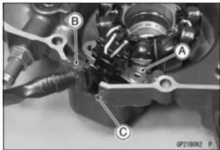
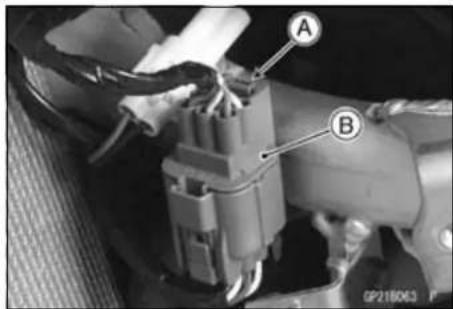
Flywheel Magneto
○Connect the hand tester [A] to the connector [B] as shown in the table 1, using the needle adapter set [C].
○Start the engine.
○Run it at the rpm given in the table 1.
○Note the voltage readings (total 2 measurements).
Special Tools - Hand Tester: 57001-1394
Needle Adapter Set: 57001-1457
Table 1 Magneto Output Voltage
| Tester Range | Connections | Reading @4 000 rpm | |
| Tester (+) to Tester (-) to | |||
| 50 V AC | Yellow/Green lead | Ground | 29 V or more |
| 50 V AC | White lead | Red lead | 25 V or more |
| 50 V AC | Blue lead | Ground | 26 V or more |
★If the output voltage shows the value in the table, the magneto operates properly.
★If the outputvoltageshowsa much lowerreading than that given in the table indicates that the magneto is defective.
- To check the stator coil resistance as follows.
○Stop the engine.
○Connect the hand tester as shown in the table 2.
○Note the readings (total 2 measurement).
Table 2 Stator Coil Resistance
| Tester Range | Connections | Reading | |
| Tester (+) to | Tester (−) to | ||
| × 1 Ω | Yellow lead | Ground | 1.6 ~ 2.3 Ω |
| × 1 Ω | White lead Red | lead | 20 ~ 50 Ω |
| × 1 Ω | Blue lead | Ground | 1.3 ~ 2.0 Ω |
★If there is more resistance than shown in the table, or no hand tester reading (infinity) the stator has an open lead and must be replaced. Much less than this resistance means the stator is shorted, and must be replaced.
- Using the highest resistance range of the hand tester, measure the resistance between each leads and chassis ground.
★Any hand tester reading less than infinity ( ∞ ) indicates a short, necessitating stator replacement.
★If the stator coils have normal resistance, but the voltage check showed the magneto to be defective; then the flywheel have probably weakened, and the flywheel must be replaced.
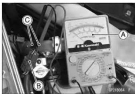
Flywheel Magneto
Charging Voltage Inspection
- Check the battery condition (see Charging Condition Inspection).
- Warm up the engine to obtain actual magneto operating conditions.
- Remove the seat (see Seat Removal in the Frame chapter).
- Connect the hand tester [A] as shown in the table.
Special Tool - Hand Tester: 57001-1394
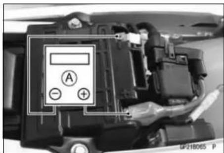
Charging Voltage
| Tester Range | Connections | Reading | |
| Tester (+) to Tester (-) to | |||
| 25 V DC | Battery (+)Terminal | Battery (-)Terminal | Battery voltage to 14.4 ±0.5 V |
- Start the engine, and note the voltage readings at various engine speeds. The readings should show nearly battery voltage when the engine speeds is low, and, as the engine speed rises, the readings should also rise. But they must be kept under the specified voltage.
- Stop the engine and disconnect the hand tester.
★If the charging voltage is kept between the values given in the table, the charging system is considered to be working normally.
★If the charging voltage is much higher than the values specified in the table, the regulator/rectifier is defective or the regulator/rectifier leads are loose or open.
★If the charging voltage does not rise as the engine speed increases, the regulator/rectifier is defective or the magneto output is insufficient for the loads. Check the magneto and regulator/rectifier to determine which part is defective.
Regulator/Rectifier Inspection
- Remove the left side cover (see Side Cover Removal in the Frame chapter).
- Disconnect the connector [A].
- Remove:
Nut [B] Regulator/Rectifier [C]
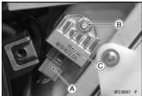
Flywheel Magneto
- With the Kawasaki hand tester, measure the internal resistance in both directions between the terminals.
Special Tool - Hand Tester: 57001-1394
★If the reading is not the specified value, replace the regulator/rectifier.
Internal Resistance (20°C) Unit: kΩ
Use only Hand Tester 57001-1394 for this test. An ohmmeter other than the Hand Tester may show different readings. If a megger or a meter with a large-capacity battery is used, the regulator will be damaged.
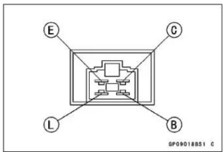
Charging System Circuit (Other than Australia Models)
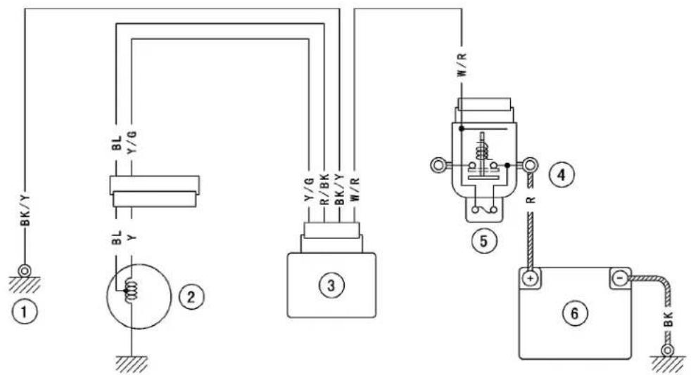
GP09210BW2 C
- Frame Ground
- Flywheel Magneto
- Regulator/Rectifier
- Starter Relay
- Main Fuse 20A
- Battery 12V 6Ah
16-24 ELECTRICAL SYSTEM
Starter Motor Clutch
Starter Motor Clutch Removal/Installation
- Refer to the Flywheel Removal/Installation.
Starter Motor Clutch Inspection
- Remove:
Torque Limiter (see Torque Limiter Removal/Installation in the Crankshaft/Transmission chapter) Magneto Cover (see Magneto Cover Removal)
- Turn the starter motor clutch gear [A] by hand. The starter motor clutch gear should turn clockwise [B] freely, but should not turn counterclockwise [C].
★If the starter motor clutch does not operate as it should or if it makes noise, go to the next step.
- Disassemble the starter motor clutch, and visually inspect the clutch parts.
★If there is any worn or damaged part, replace it.
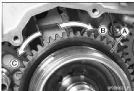
NOTE
○Examine the starter motor clutch gear as well. Replace it if it worn or damaged.
Starter Motor Clutch Disassembly
- Remove:
Flywheel (see Flywheel Removal)
Snap Ring [A]
Circlip [B]
Starter Motor Clutch [C]
Special Tool - Inside Circlip Pliers: 57001-143
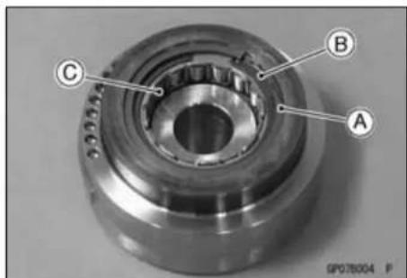
Starter Motor Clutch Assembly
- When installing the circlip, fit the projections [A] of the circlip into the slits [B] of the starter motor clutch.
Special Tool - Inside Circlip Pliers: 57001-143
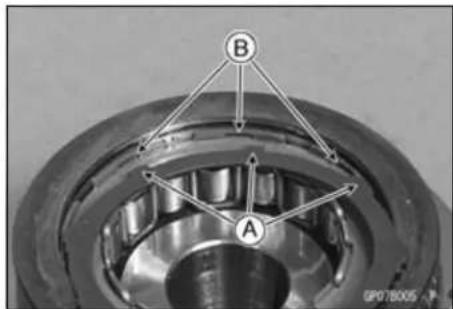
Ignition Timing
Ignition Timing Inspection
- Remove the timing inspection cap [A]. Special Tool - Filler Cap Driver: 57001-1454
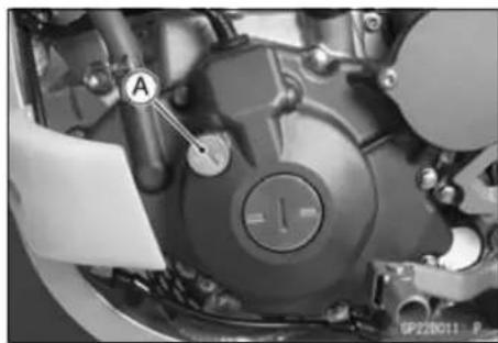
- Attach the timing light [A] to the ignition coil lead in the manner prescribed by the manufacturer. Special Tool - Timing Light: 57001-1241
- Start the engine and aim the timing light at the ignition timing mark [B] on the flywheel.
- Run the engine at the speedsspecified and note the alignment of the ignition timing marks.
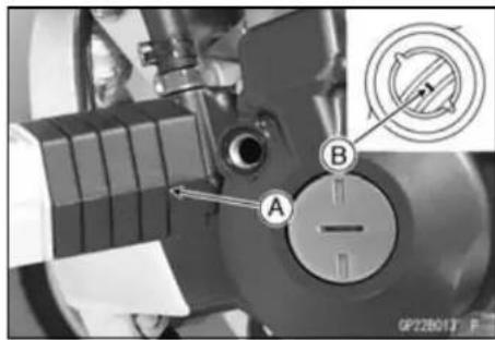
○Check the engine speed, using the engine revolution tester [A] for high accuracy.
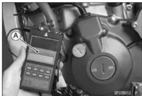
Ignition Timing
| Engine speed[r/min (rpm)] | Hole groove aligns with: |
| 1 000 | Line mark on flywheel |
★If the ignition timing is incorrect, check the crankshaft sensor (see Crankshaft Sensor Inspection).
★If the crankshaft sensor are normal, check the igniter (see Igniter Inspection).
• Install the timing inspection cap.
16-26 ELECTRICAL SYSTEM
Ignition System
Crankshaft Sensor Removal
- Refer to the Stator Removal.
Crankshaft Sensor Installation
- Refer to the Stator Installation.
Safety Instructions
WARNING
The ignition system produces extremely high voltage. Do not touch the spark plug, ignition coil or high tension lead while the engine is running, or you could receive a severe electrical shock.
Ignition Coil Removal
- Remove:
Fuel Tank (see Fuel Tank Removal in the Fuel System chapter)
Bolt [A]
Left Radiator Screen [B]
Left Radiator Mounting Bolts [C]
- Push the left radiator backward [D].
- Pry open the clamps [A].
- Disconnect the ignition coil primary lead connector [A].
- Pull the plug cap off the spark plug.
- Unscrew the mounting bolts [B], and remove the ignition coil [C].
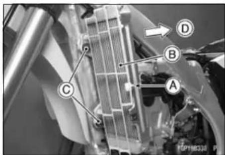
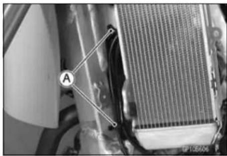
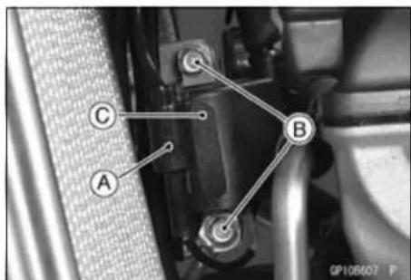
Ignition System
Ignition Coil Inspection
Measuring Arcing Distance
The most accurate test for determining the condition of the ignition coil is made by measuring arcing distance using the coil tester for the 3-needle method.
- Remove the ignition coil.
- Connect the ignition coil (with the spark plug cap left installed on the spark plug lead) [A] to the tester [B], and measure the arcing distance.
WARNING
To avoid extremely high voltage shocks, do not touch the coil body or lead.
★If the distance reading is less than the specified value, the ignition coil or spark plug cap is defective.
3 Needle Arcing Distance
Standard: 7 mm (0.26 in.) or more
- To determine which part is defective, measure the arcing distance again with the spark plug cap removed from the ignition coil lead.
★If the arcing distance is subnormal as before, the trouble is with the ignition coil itself. If the arcing distance is now normal, the trouble is with the spark plug cap.
Measuring Coil Resistance
If the arcing tester is not available, the coil can be checked for a broken or badly shorted winding with an ohmmeter. However, an ohmmeter cannot detect layer shorts and shorts resulting from insulation breakdown under high voltage.
- Remove the ignition coil (see Ignition Coil Removal).
- Measure the primary winding resistance [A].
○Connect an ohmmeter between the coil terminals.
○Set the meter to the x 1 Ω range, and read the meter.
● Measure the secondary winding resistance [B].
○Pull the spark plug cap off the lead.
○Connect an ohmmeter between the spark plug lead and the ground lead terminal.
○Set the meter to the x 1 kΩ range, and read the meter.
Ignition Coil Winding Resistance
Primary windings: 0.28 \~ 0.38 Ω (at 20°C (68°F)) Secondary windings: 7.65 \~ 10.35 kΩ (at 20°C (68°F))
★If the meter does not read as specified, replace the coil.
★If the meter reads as specified, the ignition coil windings are probably good. However, if the ignition system still does not perform as it should after all other components have been checked, test replace the coil with one known to be good.
- Check the spark plug lead for visible damage.
★If the spark plug lead is damaged, replace the coil.
Spark Plug Cleaning and Inspection
- Refer to the Spark Plug Cleaning and Inspection in the Periodic Maintenance chapter.
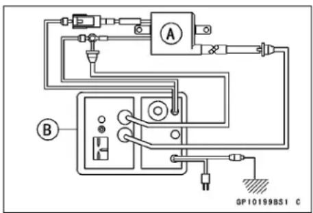
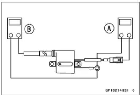
Ignition System
Spark Plug Gap Inspection
- Refer to the Spark Plug Cleaning and Inspection in the Periodic Maintenance chapter.
Igniter Removal
- Remove the right side cover (see Side Cover Removal in the Frame chapter).
- Disconnect the main harness connector [A].
- Pull out the igniter [B].
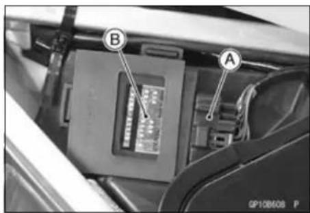
Igniter Inspection
NOTICE
When inspecting the IC Igniter observe the following to avoid damage to the IC Igniter.
Do not disconnect the IC Igniter while the engine is running.
This may damage the IC Igniter.
Ignition Coil Primary Peak Voltage Check
- Disconnect the spark plug cap from the spark plug, but do not remove the spark plug.
- Connect the good spark plug [A] to the spark plug cap, then touch the engine with it.
NOTE
○Measure the voltage with each lead connected correctly. The correct value may not be obtained if disconnected.
○Maintain the correct value of compression pressure for the cylinder (Be sure to measure the voltage with the spark plug install to the cylinder head).
- Connect the peak voltage adapter [B] between the terminal of primary lead (orange) and ground connection of the unit with the lead of the ignition coil [C] connected.
○Set the tester to DC 250 V range.
Special Tools - Hand Tester: 57001-1394
Peak Voltage Adapter: 57001-1415
Type: KEK-54-9-B
Needle Adapter Set: 57001-1457
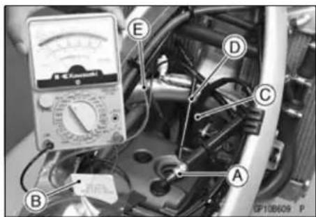
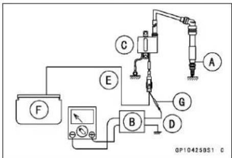
Connection: Adapter Positive → Ground Lead [D]
Adapter Negative → Orange Lead [E]
IC Igniter [F]
Needle Adapter [G]
Ignition System
- Shift the gear to the neutral position.
- Crank the engine by kicking the kick pedal and by pushing the starter button several times to measure the peak voltage of the primary ignition coil.
Ignition Coil Primary Peak Voltage
Standard: 128 V or above (Kick starter)
110 Vorabove (Electricstarter)
WARNING
Electrical equipment can cause serious electrical shock. To avoid being shocked, do not touch the metal portion of the probe when measuring voltage.
★If the voltage is less than the specified value, check the ignition coil (see Ignition Coil Inspection).
★If the ignition coil is good, check the other parts (see the flow chart in this section).
★If the all parts are good, replace the igniter.
Ignition System
![graph TD A["Faulty ignition (Malfunctioned engine)"] --> B["Battery Inspection"] B -->|Good| C["Wiring and connect portion of the ignition system inspection"] B -->|No good| D["Charge or replace battery."] C -->|Good| E["Spark plug inspection"] C -->|No good| F["Repair"] E -->|Good| G["Spark plug ca…](/content/2026/05/818283/images/ba9dd5c37c70190a4545888768504176821bab9dabf5ed6f8ddbd7a8669f037e.jpg)
Ignition System
Crankshaft Sensor Peak Voltage Check
- To check the peak voltage, do the following procedures.
○Disconnect the magneto lead connector from the main harness.
NOTE
○Measure the voltage with each lead connected correctly. The correct value may not be obtained if disconnected.
○ Maintain the correct value of compression pressure for the cylinder (Be sure to measure the voltage with the spark plug installed to the cylinder head).
○Set the hand tester to DC 2.5 V range.
○Connect the peak voltage adapter [A] to the tester and the terminals of the magneto lead connector [B].
Special Tools - Hand Tester: 57001-1394
Peak Voltage Adapter: 57001-1415
Type: KEK-54-9-B
Connection: Adapter Positive → Green/White Lead
[C]
Adapter Negative → White/Yellow
Lead [D]
○Crank the engine by kicking the kick pedal and by pushing the starter button several times with the transmission gear in neutral to measure the peak voltage of the crankshaft sensor.
Crankshaft Sensor Peak Voltage
Standard: 1.1 V or above (Kick starter)
2 V or above (Electric starter)
WARNING
Electrical equipment can cause serious electrical shock. To avoid being shocked, do not touch the metal portion of the probe when measuring voltage.
★If the voltage is less than the specified, check the crankshaft sensor (see Crankshaft Sensor Inspection).
★If the crankshaft sensor is good, check the other parts (see the flow chart in this section).
★If the all parts are good, replace the igniter.
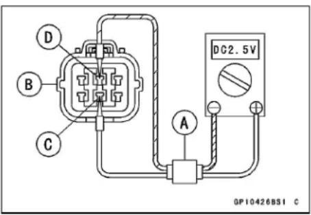
16-32 ELECTRICAL SYSTEM
Ignition System
Exciter Coil Peak Voltage Check
- Disconnect the magneto lead connector from the main harness.
- To check the peak voltage, do the following procedures.
NOTE
○Measure the voltage with each lead connected correctly. The correct value may not be obtained if disconnected.
○Maintain the correct value of compression pressure for the cylinder (Be sure to measure the voltage with the spark plug installed to the cylinder head.)
○Set the hand tester to DC 50 V range.
○Connect the peak voltage adapter [A] to the tester and the terminals of the magneto lead connector [B].
Special Tools - Hand Tester: 5701-1394
Peak Voltage Adapter: 57001-1415
Type: KEK-54-9-B
Connection: Adapter Positive → White Lead [C]
Adapter Negative → Red Lead [D]
○Crank the engine by kicking the kick pedal and by pushing the starter button several time with the transmission gear in neutral to measure the peak voltage of the exciter coil.
Exciter Coil Peak Voltage
Standard: 36 V or Above (Kick starter)
33 V or above (Electric starter)
★If the voltage is less than the specified, check the exciter coil (see Flywheel Inspection).
★If the exciter coil is good, replace the igniter.
Throttle position sensor Inspection
- Remove the fuel tank transiently (see Fuel Tank in the Fuel System chapter).
- Disconnect the throttle position sensor lead connector [A].
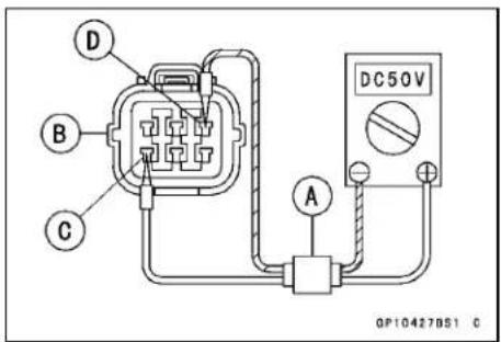
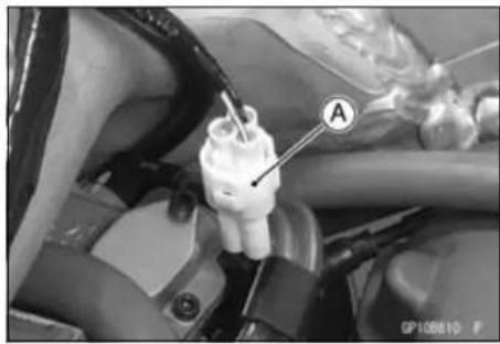
Ignition System
- Connect the throttle position sensor setting adapter [A] between throttle position sensor lead connector [B] and main harness connector [C].
Special Tools - Hand Tester: 57001-1394
Throttle Position Sensor Setting Adapter
1: 57001-1400
- Set the hand tester [D] to the DC 10 V range, and connect it to the adapter leads.
Hand Tester (+) → Blue Lead
Hand Tester (−) → Black/Blue Lead
- Temporary install the fuel tank.
- Start the engine.
- Check the sensor input voltage with the engine running.
Throttle Position Sensor Input Voltage
Standard: around 5 V
★If it is not within the specified voltage, replace the igniter.
★If it is within the specified voltage, go to the next step.
- To check the output voltage, do the following procedures.
○Connect the digital voltmeter [A] as follows.
Tester (+) → Yellow/White Lead
Tester (−) → Black/Blue Lead
○Start the engine.
○Measure the throttle position sensor output voltage with the engine idling speed.
Throttle Position Sensor Output Voltage
Standard: 0.58 \~ 0.78 V (when engine is idle speed)
★If it is not within the specified voltage range, adjust the throttle sensor position (see Throttle Position Sensor Position Adjustment).
★If the throttle position sensor position is good, inspect the other parts (see the previous flow chart).
★If the all parts are good, replace the igniter.
Throttle Position Sensor Resistance Inspection
- Disconnect the throttle position sensor lead connector from the main harness.
- Set the hand tester to the × 100 Ω range, and connect it to the throttle position sensor lead connector.
Throttle Position Sensor Resistance
Connections: Blue Lead ← → Black Lead
Service Limit: 4 \~ 6 kΩ
★If the reading is out of the range, replace the throttle position sensor.
★If the reading is within the specified range, check the other parts (see the previous flow chart).
★If the all parts are good, replace the igniter.
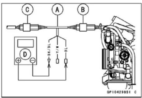
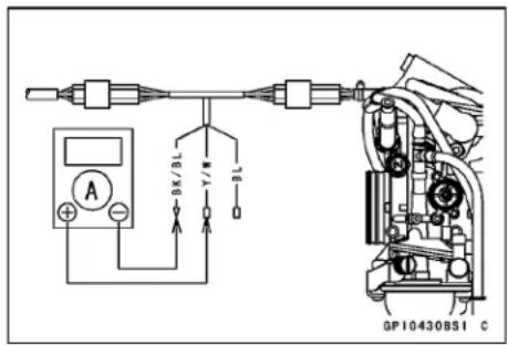
Ignition System
Throttle Position Sensor Position Adjustment
- Check the idle speed, using the engine revolution tester for high accuracy and adjust the idle speed specified (see Idle Speed Inspection in the Periodic Maintenance chapter).
- Disconnect the throttle position sensor lead connector and connect the throttle position sensor setting adapter between throttle position sensor lead connector and main harness connector.
Special Tools - Hand Tester: 57001-1394
Throttle Position Sensor Setting Adapter
1: 57001-1400
- Set the hand tester to the 2.5 V DC range.
Hand Tester (+) → Yellow/White Lead
Hand Tester (−) → Black/Blue Lead
- Temporary install the fuel tank.
- Start the engine.
- Check the sensor output voltage at the idle speed.
Throttle Position Sensor Output Voltage
Standard: 0.58 \~ 0.78 V (when engine is idle speed)
- Adjust the position of the throttle position sensor so the voltage is within the specified voltage, and tighten the sensor bolt.
Crankshaft Sensor Inspection
- Remove:
Magneto Lead Connector (see Magneto Cover Removal). - Set the hand tester [A] to the × 100 Ω range and connect it to the Green/White [B] and White/Yellow [C] Leads in the connector.
Special Tool - Hand Tester: 57001-1394
★If there is more resistance than the specified value, the coil has an open lead and must be replaced. Much less than this resistance means the crankshaft sensor is shorted, and must be replaced.
Crankshaft Sensor Resistance
Standard: 190 \~ 290 Ω (at 20 °C (68 °F))
- Using the highest resistance range of the tester, measure the resistance between the crankshaft sensor leads and chassis ground.
★Any tester reading less than infinity ( ∞ ) indicates a short, necessities replacement of the crankshaft sensor assembly.
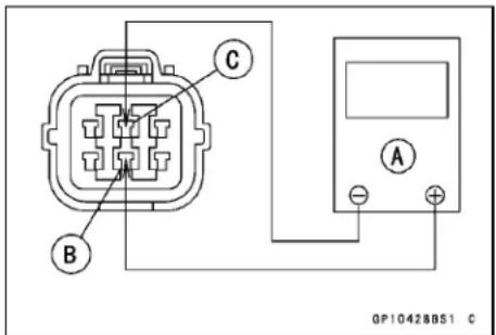
Ignition System
Ignition System Circuit (Other than Australia Models)
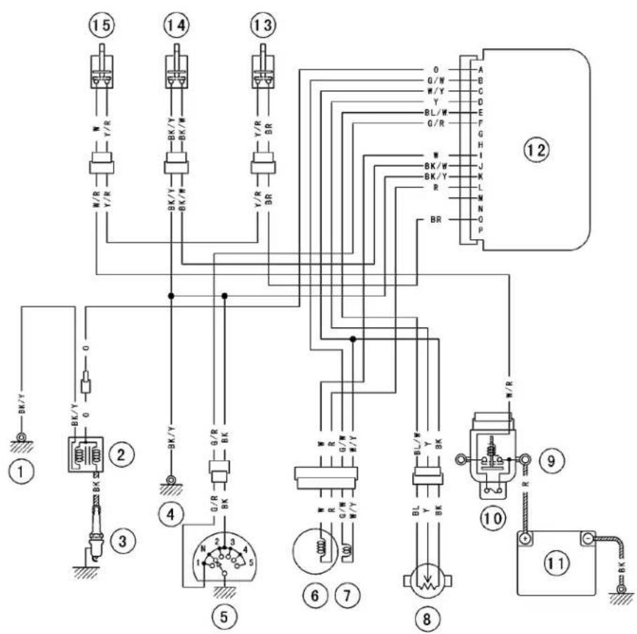
GP10432BH3 C
- Frame Ground
- Ignition Coil
- Spark Plug
- Frame Ground
- Gear Position Switch
- Flywheel Magneto
- Crankshaft Sensor
-
Throttle Position Sensor
-
Starter Relay
- Main Fuse 20 A
- Battery 12 V 6 Ah
- IC Igniter
- Engine Starter Button
- Engine Stop Switch
- Starter Lockout Switch
16-36 ELECTRICAL SYSTEM
Electrical Starter System
Starter Motor Removal
- Remove:
Exhaust Pipe (see Muffler Removal in the Engine Top End chapter)
Starter Motor Terminal Nut [A]
Starter Motor Mounting Bolts [B]
- Pull out the starter motor to right side.
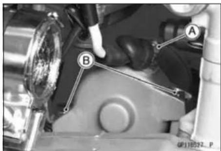
Starter Motor Installation
NOTICE
Do not tap the starter motor shaft or body. Tapping the shaft or body could damage the motor.
- Clean the starter motor mounting surface [A] and the crankcase surface [B] (mating surface with starter motor mounting).
- Replace the O-ring [A] with a new one.
- Apply engine oil to the O-ring.
Torque - Starter Motor Mounting Bolts: 9.8 N·m (1.0 kgf·m, 87 in·lb)
Starter Motor Terminal Nut: 5.9 N·m (0.60 kgf·m, 52 in·lb)
• Install the starter motor.
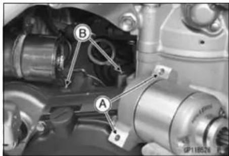
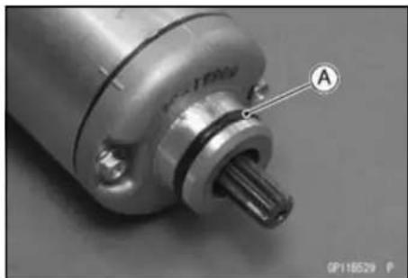
Starter Motor Disassembly
- Remove the starter motor (see Starter Motor Removal).
- Remove:
Starter Motor Assembly Bolts [A] Both End Covers [B]
- Pull the armature out of the yoke.
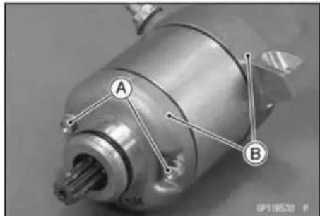
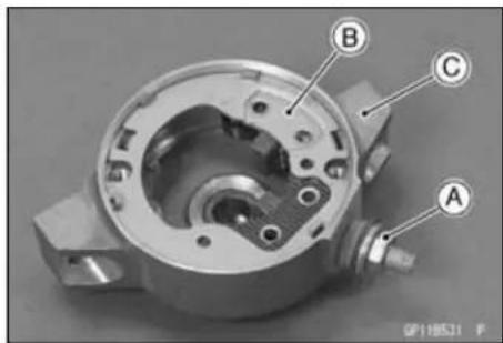
- Remove the terminal locknut [A] and then remove the brush with the brush plate [B] from the end cover [C].
Electrical Starter System
Starter Motor Assembly
- Replace the O-ring with a new one.
- Apply a thin coat of high-temperature grease to the oil seal [A] and the needle bearing [B].
- Fit the toothed washer [C] into the end cover.
Thin Washer [D] Thick Washer [E]
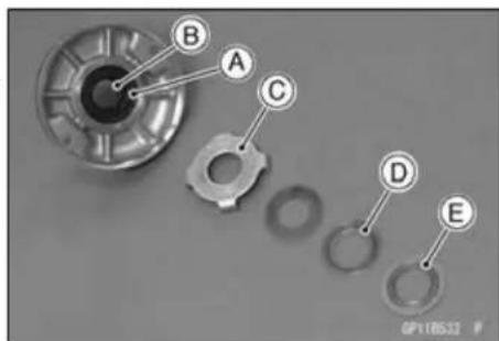
- Install the brush plate [A] and tighten the terminal locknut [B].
Torque - Starter Motor Terminal Locknut: 6.9 N·m (0.70 kgf·m, 61 in·lb)
- Fit the tongue [C] on the brush plate into the end cover groove.
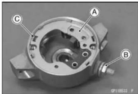
- Insert the armature [A] between the brushes.
Thin Washer [B] Thick Washer [C]
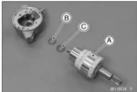
- Align the marks [A] of the yoke [B] and end covers [C].
Torque - Starter Motor Through Bolts: 3.4 N·m (0.35 kgf·m, 30 in·lb)
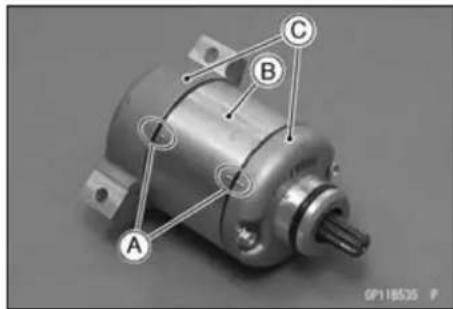
Carbon Brush Inspection
- Measure the length [A] of each brush.
★If any one is worn down to the service limit, replace the carbon brush holder assembly [B].
Carbon Brush Length
Standard: 10 mm (0.39 mm)
Service Limit: 6.5 mm (0.26 in.)
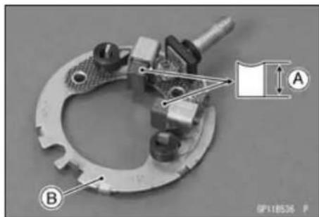
16-38 ELECTRICAL SYSTEM
Electrical Starter System
Commutator Inspection, Cleaning
- Smooth the commutator surface [A] if necessary with fine emery cloth [B], and clean out the grooves.
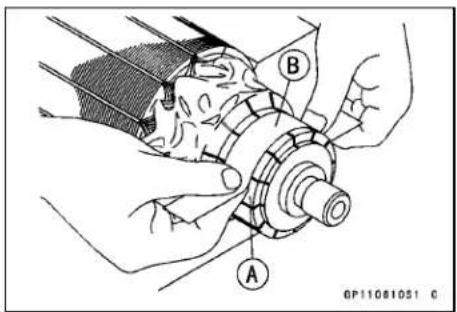
● Measure the outer diameter [A] of the commutator [B].
★Replace the starter motor with a new one if the commutator diameter is less than the service limit.
Commutator Diameter
Standard: 28 mm (1.10 in.)
Service Limit: 27 mm (1.06 in.)
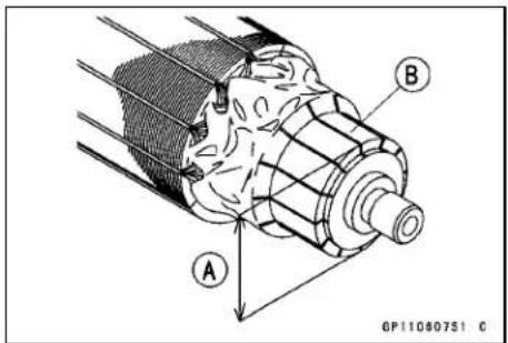
Armature Inspection
- Using the × 1Ω hand tester range, measure the resistance between any two commutator segments [A].
★If there is a high resistance or no reading ( ∞ ) between any two segments, a winding is open and the starter motor must be replaced. - Using the × k Ω hand tester range, measure the resistance between the segments and the shaft [B].
★If there is any reading at all, the armature has a short and the starter motor must be replaced.
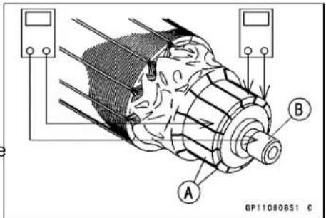
Special Tool - Hand Tester: 57001-1394
NOTE
○Even if the foregoing checks show the armature to be good, if may be defective in some manner not readily detectable with the hand tester. If all other starter motor and starter motor circuit components check good, but the starter motor still does not turn over or only turns over weakly, replace the starter motor with a new one.
Brush Lead Inspection
- Using the x 1 Ω hand tester range, measure the continuity between the following:
Terminal Bolt and Positive (+) Brush [A]
Brush Plate and Negative (−) Brush [B]
★If there is not close to zero ohms, the brush lead has an open. Replace the terminal bolt assembly and the brush holder assembly.
Special Tool - Hand Tester: 57001-1394
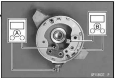
Electrical Starter System
Terminal Bolt Inspection
- Using the highest hand tester range, measure the resistance as shown.
Terminal Bolt and Brush Plate [A]
Terminal Bolt and Negative Brush Holder [B]
Terminal Bolt and End Cover [C]
★If there is any reading, the brush holder assembly and/or terminal bolt assembly have a short. Replace the brush holder assembly and the terminal bolt assembly.
Special Tool - Hand Tester: 57001-1394
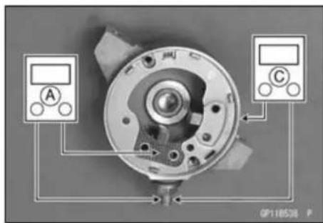
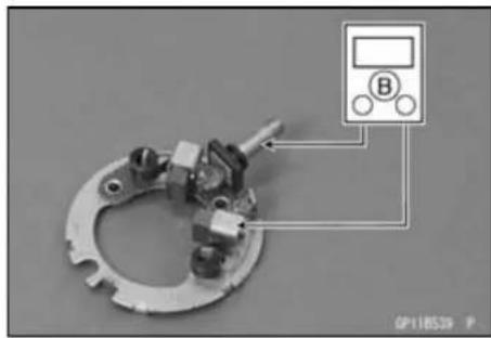
Starter Relay Inspection
- Remove the seat (see Seat Removal in the Frame chapter).
- Disconnect the connector [A].
- Disconnect the starter motor cable [B] and batterypositive (+) cable [C] from the starter relay [D].
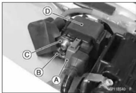
- Connect the hand tester [A] and 12 V battery [B] to the starter relay [C] as shown.
★If the relay does not work as specified, the relay is defective. Replace the relay.
Starter Relay Inspection
Tester range: × 1 Ω
Standard: When battery is connected → 0 Ω
When battery is disconnected → ∞ Ω
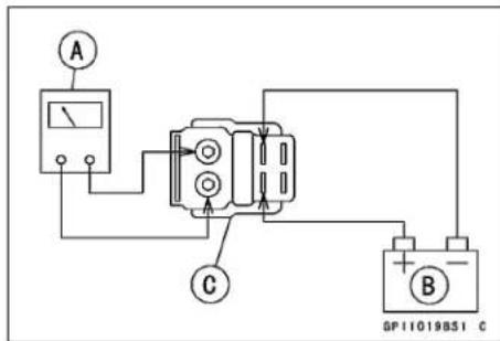
Special Tool - Hand Tester: 57001-1394
Electrical Starter System
Electric Starter Circuit (Other than Australia Models)
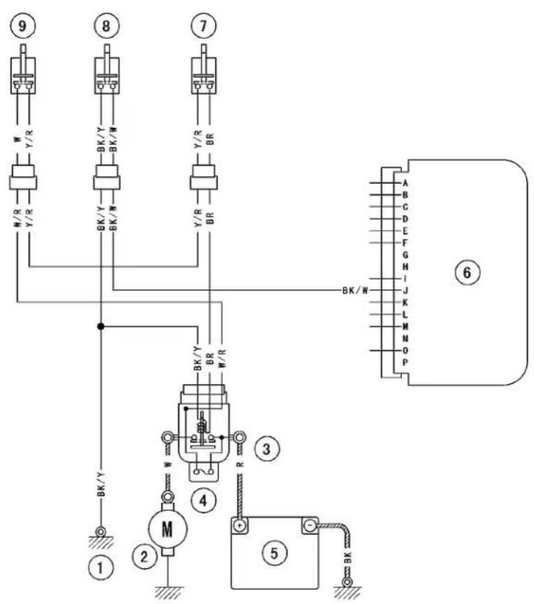
GP11122BW3 C
- Frame Ground
- Starter Motor
-
Starter Relay
-
Main Fuse 20 A
- Battery 12 V 6 Ah
-
IC Igniter
-
Engine Starter Button
- Engine Stop Switch
- Starter Lockout Switch
Lighting System
Headlight Aiming Inspection
- Inspect the headlight beam for aiming.
★If the headlight beam points too low or high, adjust the vertical beam.
Headlight Beam Vertical Adjustment
- Turn the vertical adjuster [A] on the headlight with the screwdriver in or out to adjust the headlight vertically.
NOTE
○ ON high beam, the brightest points should be slightly below horizontal with the motorcycle on its wheels and the rider seated. Adjust the headlight to the proper angle according to local regulations.
Headlight Bulb Replacement
- Remove:
Headlight Assy (see Headlight Removal/Installation) Headlight Bulb Dust Cover [A] - Open the clamp [B] and free the headlight lead [C].
- Remove: Headlight Connector [A]
- Remove: Hook [A] Headlight Bulb [B]
NOTICE
When handling the quartz-halogen bulb, never touch the glass portion with bare hands. Always use a clean cloth. Oil contamination from hands or dirty rags can reduce bulb life or cause the bulb to explode.
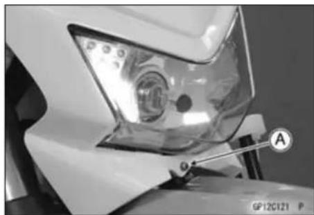
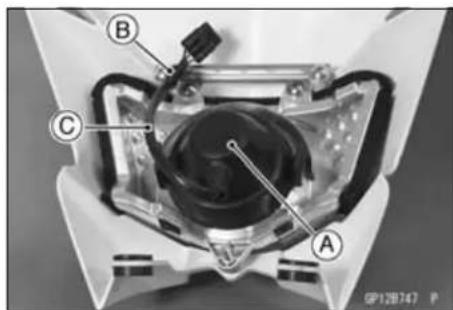
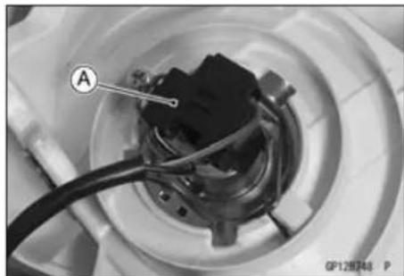
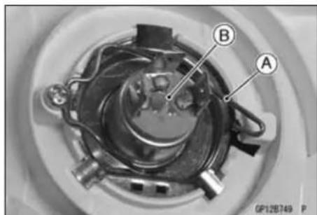
NOTE
○ Clean off any contamination that inadvertently gets on the bulb with alcohol or soap and water solution.
- Replace the headlight bulb.
- Fit the projections [A] of the bulb in the hollow [B] of the headlight.
- Install the hook [C].
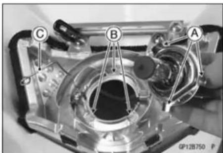
- Fit the dust cover [A] firmly so that the headlight lead [B] faces downward [C] as shown.
- After installation, adjust the headlight aim (see Headlight Aiming Inspection in the Periodic Maintenance chapter).
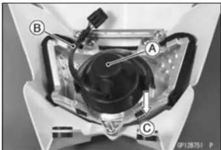
Headlight Removal/Installation
- Remove the mounting bolts [A].
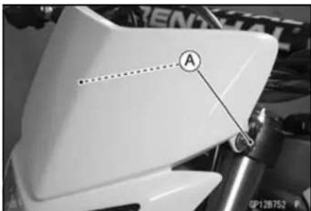
- Disconnect the headlight connector [A].
- Remove the headlight assy.
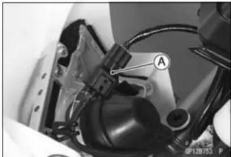
- Installation is the reverse of removal. ○Fit the projections [A] of the steering stem into the grommets [B] of the headlight assy.
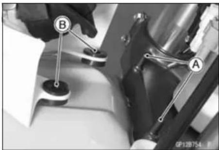
Lighting System
Tail Light Removal
- Remove the seat (see Seat Removal in the Frame chapter).
- Disconnect the tail light lead connector [A].
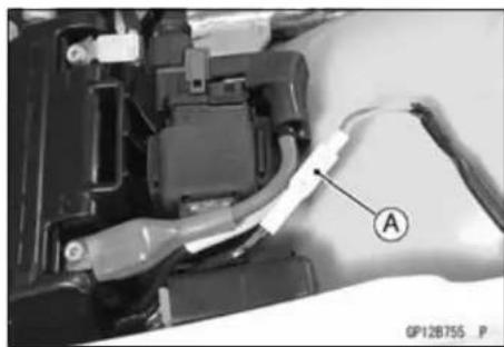
- Unhook the tail light lead [A] from the clamps [B].
- Unscrew the bolts [C] and remove the tail light [D].
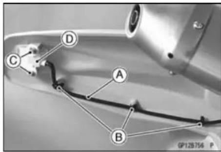
Tail Light Installation
- Installation is the reverse of removal, note the following. - Route the harness and leads correctly (see Cable, Wire, and Hose Routing section in the Appendix chapter).
Lighting System
Headlight/Tail Light Circuit (Other than Australia Models)
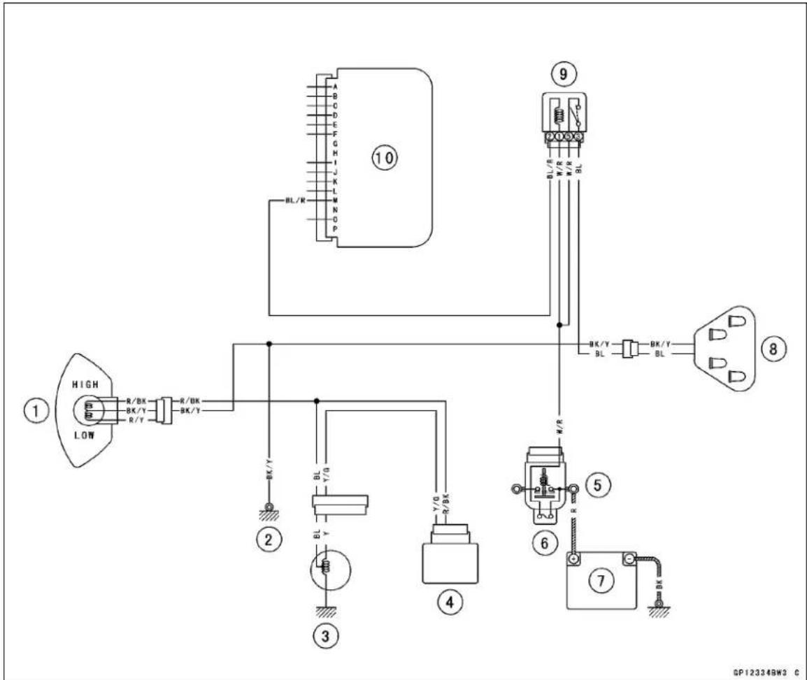
- Headlight
- Frame Ground
- Flywheel Magneto
- Regulator/Rectifier
-
Starter Relay
-
Main Fuse 20 A
- Battery 12 V 6 Ah
- Tail Light
- Main Relay
- IC Igniter
Meter Gauge
Meter Unit Removal/Installation
- Remove the headlight assy (see Headlight Removal/Installation).
- Remove the mounting nuts [A].
- Slide the boots [B] and disconnect the meter connector [C].
- Installation is reverse of removal.
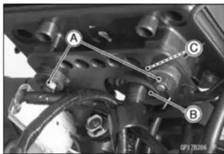
Meter Unit Disassembly/Assembly
- Remove:
Screws [A]
Lower Meter Cover [B]
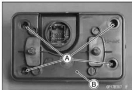
- Remove:
Screws [A]
Meter Assy [B]
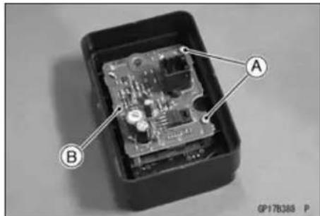
- Assembly is reverse of Disassembly.
Switch Inspection
- Starting the engine causes all the LCD segments (the letters and numbers of the liquid crystal display) [A] illuminate for 3 seconds.
★If they do not illuminate, check the LCD segments (see LCD Segment Inspection).
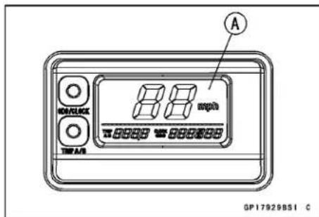
16-46 ELECTRICAL SYSTEM
Meter Gauge
- Check that the display [A] shifts between ODO and CLOCK each time the ODO/CLOCK button [B] is pushed.
★If the display does not shift, replace the meter unit.

- Check that the display [A] shifts between TRIP-A and TRIP-B each time the TRIP A/B button [B] is pushed.
★If the display does not shift, replace the meter unit.
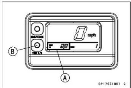
- Push the ODO/CLOCK button [A] to display the clock.
- Keeping the TRIP A/B button pushed, turning ON the ODO/CLOCK button [B] enables the hours and the minutes of the clock to be set [C]. Verify that the time can be set here.
★If the time cannot be set, replace the meter unit.
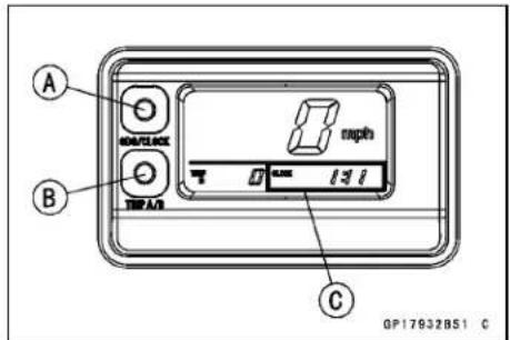
Clock Setting
- Press the ODO/CLOCK button [A] to show the clock in the odometer display.
- Keep the ODO/CLOCK button pressed and turn the TRIP A/B button [B] ON to enable the display to assume the Hour/Minute setting mode [C] in which the numbers flash, thus enabling you to set the time on the clock.
○Starting with the Hour/Minute setting mode, each pressing of the ODO/CLOCK button changes the setting modes as follows:
Hour/Minute Setting Mode → Hour Setting Mode → Minute Setting Mode
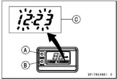
Meter Gauge
In the Hour/Minute setting mode, the numbers that represent the hours and the minutes flash. In the Hour setting mode, the numbers that represent the hours flash [A]. And in the Minute setting mode, the numbers that represent the minutes flash [B].
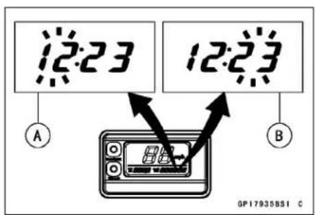
- In the Hour setting mode and the Minute setting mode, set the time by pressing the TRIP A/B button [A] to increase the number of Hours and Minutes.
- Then, change to the Hour/Minute setting mode and press the TRIP A/B button to complete the time setting process.
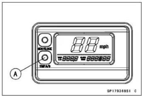
LCD Segment Inspection
- Remove:
Headlight Assy (see Headlight Removal/Installation) Meter Unit (see Meter Unit Removal/Installation)
- Check that all the LCD segments (the letters and numbers of the liquid crystal display) illuminate for 3 seconds after connecting pins [4] and [8] of the meter connector [A] to the battery [B], then connecting pin [2] and battery (+) terminal together. Next, check that all the LCD segments become unlit when pin [2] is disconnected.
★If there is any problem, replace the meter unit.
★If there are no problems, inspect the power wiring.
NOTE
○ In case that the Liquid Crystal Display (LCD) malfunctions, e.g., display freezing, wait for 30 seconds or more after disconnecting it from the battery.
The LCD will function normally after reconnected.
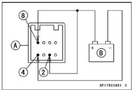
Meter Gauge
Meter Circuit (Other than Australia Models)
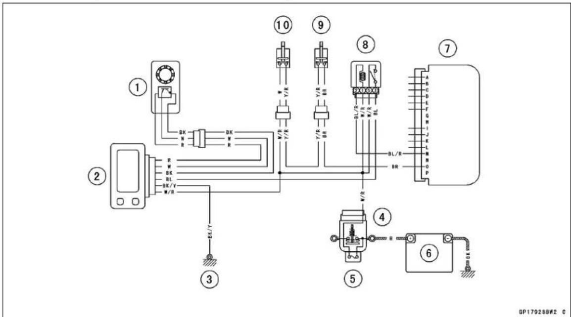
- Speed Sensor
- Meter Unit
- Frame Ground
- Starter Relay
-
Main Fuse 20 A
-
Battery 12 V 6 A
- IC Igniter
- Main Relay
- Engine Starter Button
- Starter Lockout Switch
Switches and Sensors
Speed Sensor Removal
- Disconnect the speed sensor connector [A] and remove the sensor lead from the clamp.
- Remove the bolts [A] and open the clamps [B], take off the sensor lead.
- Remove the front wheel with the speed sensor (see Front Wheel Removal in the Wheels/Tires chapter).
Speed Sensor Installation
- Install the front wheel with the speed sens or (see Front Wheel Installation in the Wheels/Tires chapter).
- Install the sensor cable [A] into the clamps [B] and connect the connector [C].
Speed Sensor Inspection
- Remove the speed sensor (see Speed Sensor Removal).
- Connect the speed sensor connector [A] with the battery [B], 10 kΩ resistor [C] and hand tester [D] as shown.
- Set the tester to the DC 25 V range.
Special Tool - Hand Tester: 57001-1394
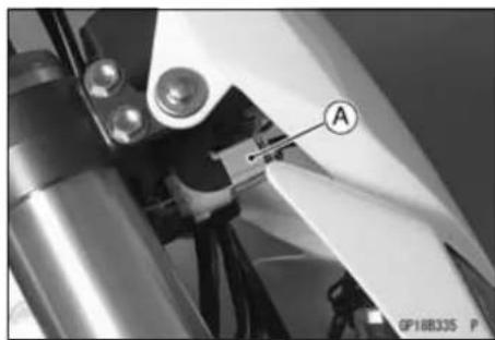

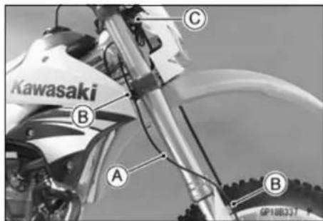
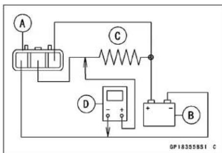
Switches and Sensors
- Turn [A] the rotor of the speed sensor.
○Then the tester indicator should flick [B].
★If the tester indicator does not flick, replace the speed sensor.
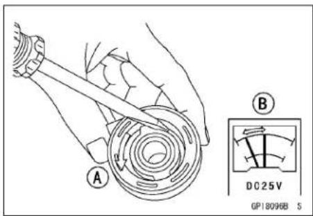
Throttle Position Sensor Removal/Installation
- Refer to the Carburetor Disassembly/Assembly in the Fuel System chapter.
Switch Inspection
- Using the hand tester, check to see that only the connections shown in the table have continuity (about zero ohms).
Special Tool - Hand Tester: 57001-1394
★If the switch has an open or short, repair it or replace it with a new one.
| Engine Stop Switch Connections | ||
| Color | BK/Y | BK/W |
| OFF | ||
| RUN | ○— | ○ |
| Starter Button | ||
| Color | Y/R | BR |
| Push | ○ | ○ |
| Release | ||
| Starter Lockout Swith | ||
| Color | W | Y/R |
| Clutch Lever | ||
| Pulled in | ○——○ | |
| Released | ||
QP18352BN3 C
OP18353BN3 C
Gear Position Switch Removal
- Remove:
Left Radiator Shroud
Bolt [A]
Left Radiator Screen [B]
Left Radiator Mounting Bolts [C]
- Push the left radiator backward [D].
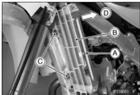
Switches and Sensors
- Pry open the clamps [A].
- Disconnect the gear position switch connector.
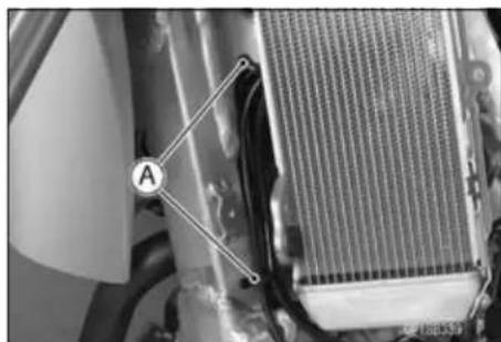
- Remove:
Shift Pedal (External Shift Mechanism Removal in the Engine Right Side chapter) Screws [A] Gear Position Switch [B]
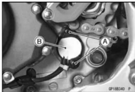
- Remove:
O-ring [A] Gear Position Switch Finger [B] Spring [C]
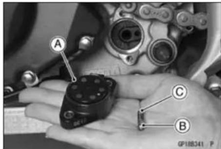
Gear Position Switch Installation
- Insert the spring into the hole in the shift drum.
- Insert the switch finger [A] so that the small diameter [B] is toward hole side.
- Apply grease to the O-ring.
- Clean the contact points on the position sensor.
- Apply a non-parmanent locking agent to the gear position switch screws.
- Tighten:
Torque - Gear Position Switch Screws: 2.9 N·m (0.30 kgf·m, 26 in·lb)
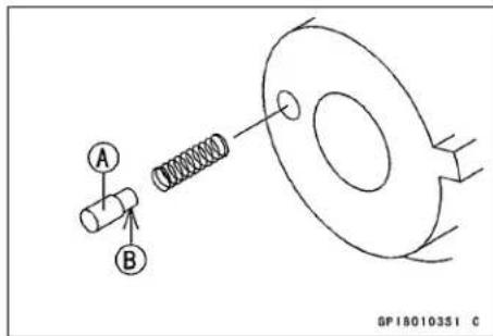
- Install the other removed parts.
Switches and Sensors
Gear Position Switch Inspection
NOTE
○ Be sure the transmission mechanism is good condition.
- Remove the left radiator shroud.
- Disconnect the gear position switch lead connector [A].
- Set the hand tester [A] to the ×1 kΩ or ×100 Ω range and connect it to the terminals in the gear position switch lead connector [B] and ground.
[C] Internal Circuit
[D] Green/Red Lead
[E] Black Lead
Special Tool - Hand Tester: 57001-1394
Gear Position Switch Resistance
| Connections | ||
| Gear Position | [D] Terminal - Ground [E] Terminal - Ground | |
| 1st | 3.00 ~ 3.32 kΩ | 11.64 ~ 12.86 kΩ |
| Neutral | 1.70 ~ 1.89 kΩ | 10.35 ~ 11.43 kΩ |
| 2nd | 1.07 ~ 1.19 kΩ | 9.71 ~ 10.73 kΩ |
| 3rd | 0.695 ~ 0.769 kΩ | 9.33 ~ 10.31 kΩ |
| 4th | 0.430 ~ 0.476 kΩ | 9.07 ~ 10.0 kΩ |
| 5th | 0.248 ~ 0.274 kΩ | 8.88 ~ 9.82 kΩ |
★If the tester reading is not as specified, replace the gear position switch with a new one.
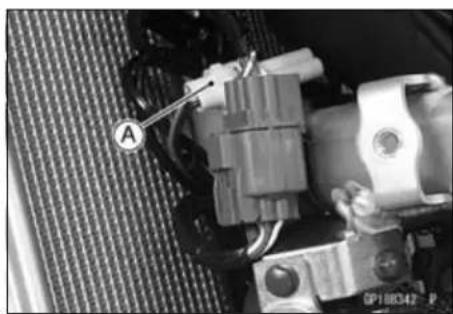
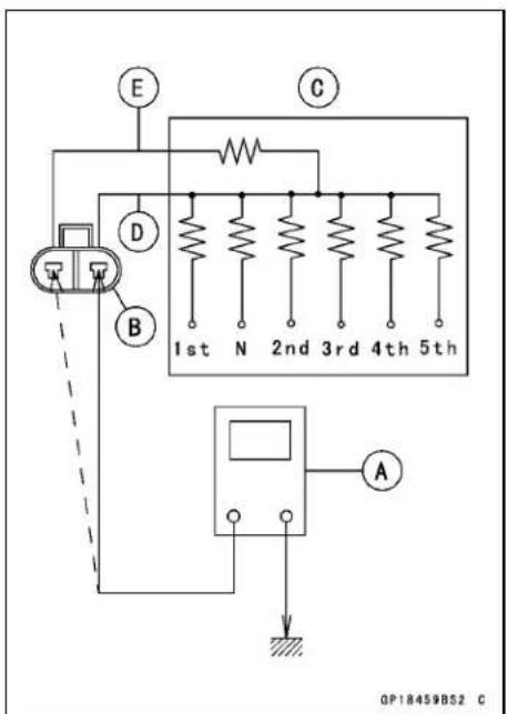
Main Relay
Main Relay Inspection
- Remove the seat (see Seat Removal in the Frame chapter).
- Remove the main relay [A].

- Check conductivity of the following numbered terminals by connecting the hand tester and one 12 V battery to the main relay as shown.
★If the tester does not read as specified, replace the main relay.
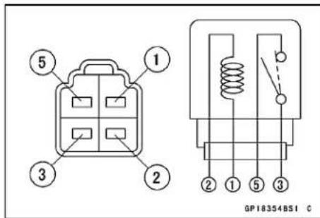
Main Relay Inspection (with the battery disconnected)
| Tester Connection Tester Reading (Ω) | |
| 3-5 | ∞ |
| 1-2 | Not∞* |
*: The actual reading varies with the hand tester used.
Main Relay Inspection (with the battery connected)
| Battery Connection (+) (-) | Tester Connection | Tester Reading (Ω) |
| 1-2 3-5 0 |
(+): Apply positive lead.
(-): Apply negative lead.
- Remove the seat (see Seat Removal in the Frame chapter).
- Disconnect the starter relay connector [A].
- Removethemainfuse[B]fromthestarter
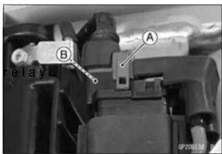
Main Fuse 20 A Inspection
- Removethe fuse (see MainFuse20A Rem spect the fuse element.
★If the fuse element is blown, replace the fuse.
Housing [A]
Fuse Element [B]
Terminal [C]
Blown Element [D]
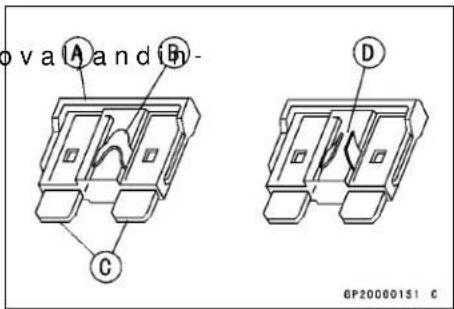
NOTICE
When replacing a fuse, be sure the new fuse matches the specified fuse rating for that circuit. Installation of a fuse with a higher rating may cause damage to wiring ad components.
Appendix
Table of Contents
Cable, Wire, and Hose Routing 17-2
Troubleshooting Guide 17-25
17-2 APPENDIX
Cable, Wire, and Hose Routing
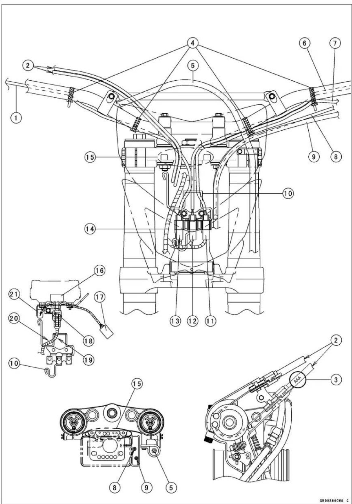
Cable, Wire, and Hose Routing
- Starter Button Lead
- Throttle Cables
- Marked (AAA) cable is accelerator side.
- Bands
- Brake Hose
- Engine Stop Switch Lead
- Starter Lockout Switch Lead
- Hot Starter Cable
- Clutch Cable
- Harness/Cable Guide
- Starter Lockout Switch Connector (Green)
- Engine Stop Switch Connector (White)
- Starter Button Lead Connector (Black)
- Meter Unit Lead
- Run the throttle cables and Leads between the meter bracket and upper mounting.
- Meter Unit Connector (Black Cap)
- Headlight Connector (Black)
- Clamp (Fix the leads by twisting the clamp.)
- Front side of the harness/cable guide.
- Inside of the harness/cable guide.
- Speed Sensor Lead Connector (Gray)
17-4 APPENDIX
Cable, Wire, and Hose Routing
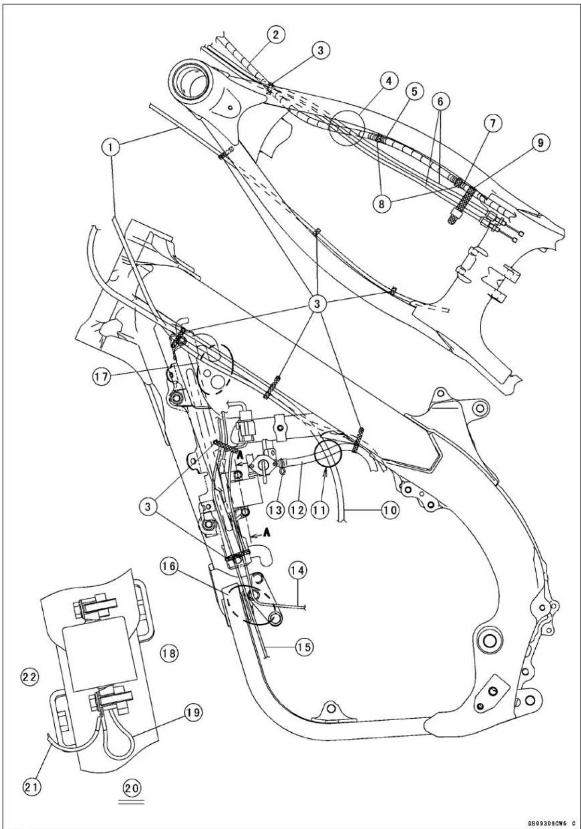
Cable, Wire, and Hose Routing
- Hot Starter Cable
- Main Harness
- Clamps
- Run the throttle cables over the main harness.
- White Tape
- Throttle Cables
- Blue Tape
- Clamps
- Band
- Clutch Cable
- Run the clutch cable outside of the fuel hose.
- Fuel Hose
- Clamp (Face the tab to the underside.)
- Magneto Lead
- Transmission Position Sensor Lead
- If the magneto lead and transmission position sensor lead have the play, do no play by pulling down them.
- Run the hot starter cable and clutch cable over the radiator hose.
- Right Side
- Ignition Coil Ground Lead
- View from A-A
- Ground Lead
- Left Side
17-6 APPENDIX
Cable, Wire, and Hose Routing
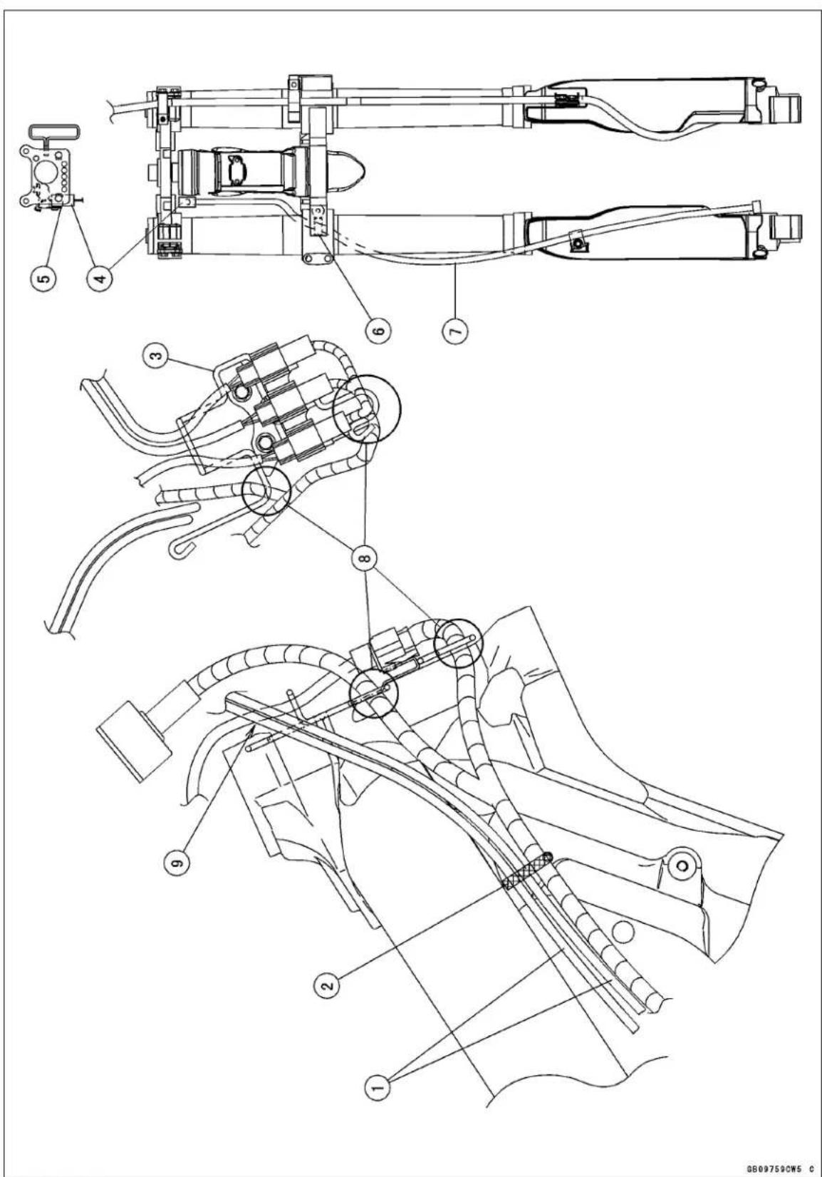
Cable, Wire, and Hose Routing
- Throttle Cables
- Clamp
- Harness/Cable Guide
- Speed Sensor Lead Connector (Gray)
- Fix the connector on the bracket.
- Clamp (Put the sensor grommet into the clamp, and then fix it by crushing the clamp.)
- Speed Sensor Lead
- Run the harnesses to inside of the clamp.
- Run the switch lead to inside of the throttle cables.
17-8 APPENDIX
Cable, Wire, and Hose Routing
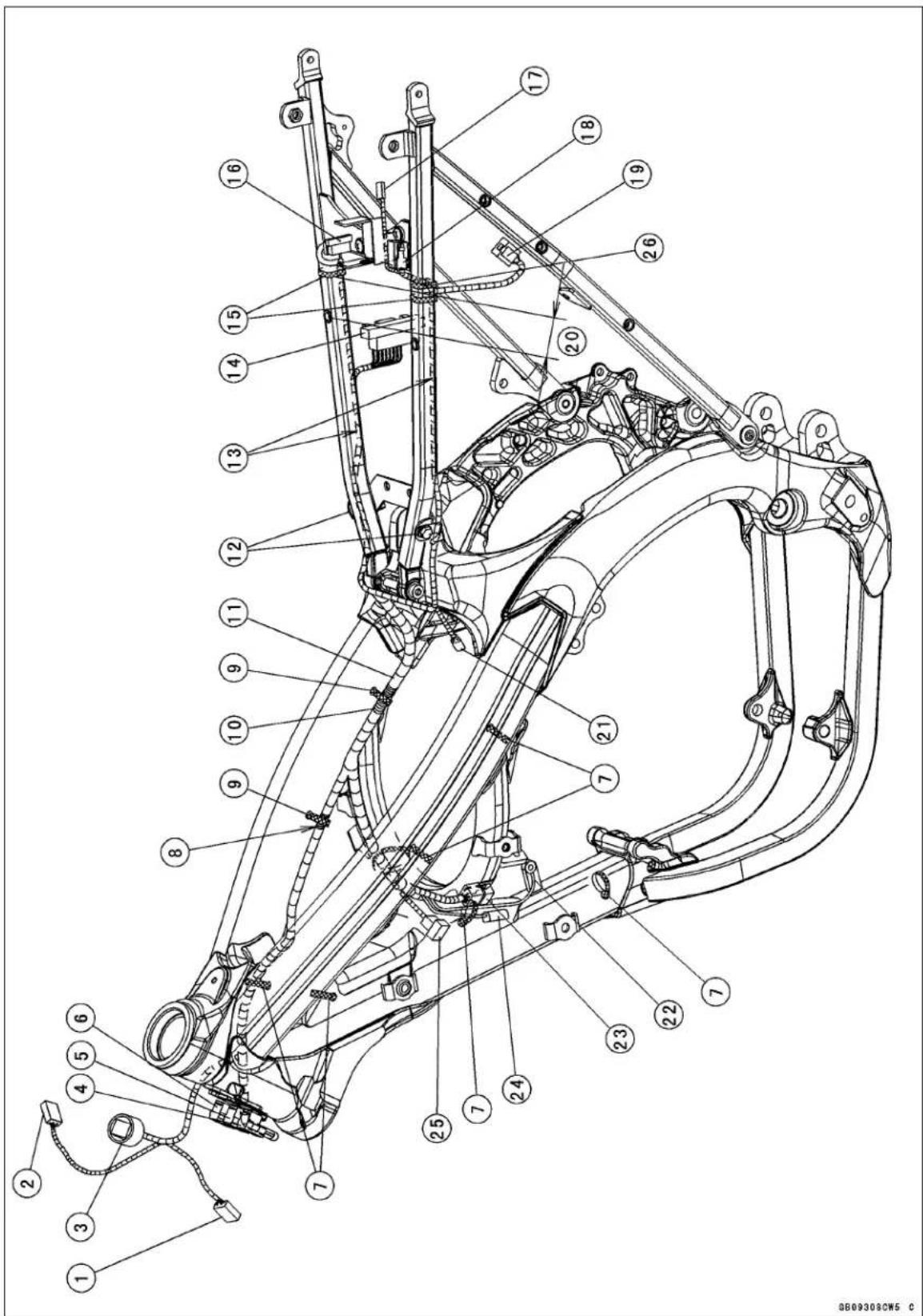
Cable, Wire, and Hose Routing
- Headlight Connector (Black)
- Speed Sensor Lead Connector (Gray)
- Meter Unit Connector (Black Cap)
- Starter Lockout Switch Connector (Green)
- Engine Stop Switch Connector (White)
- Starter Button Lead Connector (Black)
- Clamps
- White Tape
- Clamps
- Blue Tape
- Main Harness
- Clamps
- Run the harnesses under the frame pipe.
- Igniter Connector (Black)
- Bands
- Starter Relay Connector (Red)
- Tail Light Lead Connector (White)
- Main Relay Connector (White)
- Regulator/Rectifier Lead Connector (Green)
- 50 mm (2.0 in.)
- Throttle Position Sensor Lead Connector (White)
- Ground Lead
- Magneto Lead Connector (Gray)
- Ignition Coil Lead Connector (Black)
- Transmission Position Sensor Lead Connector (White)
- Clamp (Fix only the main relay lead.)
17-10 APPENDIX
Cable, Wire, and Hose Routing
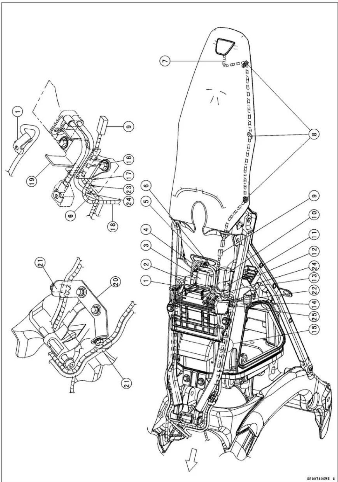
Cable, Wire, and Hose Routing
- Battery Negative (−) Cable (Black)
- Starter Relay Connector (Red)
- Starter Relay
- Black Cap
- Battery Positive (+) Cable (Red)
- Starter Motor Cable (White)
- Tail Light Lead
- Clamps (Fix the tail light lead by twisting the clamps.)
- Tail Light Lead Connector (White)
- Main Relay
- Main Relay Connector (White)
- Regulator/Rectifier
- Regulator/Rectifier Lead Connector (Green)
- Run the regulator/rectifier lead to the inside of the front left side cover mounting bracket of the air cleaner housing.
- Run the main harness and starter motor cable under the frame pipe.
- Run the tail light lead to the most bottom of grooves on the U shaped bracket.
- To Main Relay
- To Regulator/Rectifier
- Bracket
- Bracket
- Clamps (Tightened together with the bracket.)
- Clamp (Fix only the main relay lead.)
- Run the tail light lead to inside of the main relay lead.
- Run the starter motor cable to inside of the main relay lead.
- Place the band at the hollow of the battery holder.
17-12 APPENDIX
Cable, Wire, and Hose Routing
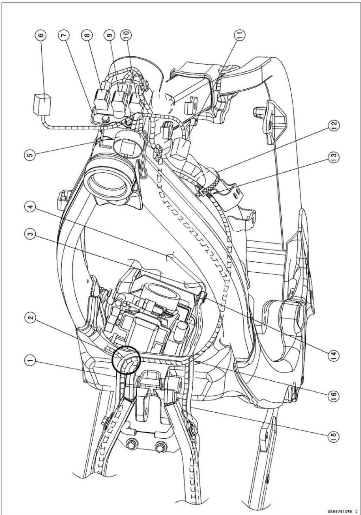
Cable, Wire, and Hose Routing
- Starter Motor Cable (White)
- Run the starter motor cable over the harness.
- Tighten together the battery negative (−) cable and starter mounting bolt.
- Connect the starter motor cable to the starter motor terminal bolt.
- Meter Unit Connector (Black Cap)
- Headlight Connector (Black)
- Harness/Cable Guide
- Starter Lockout Switch Connector (Green)
- Engine Stop Switch Connector (White)
- Starter Button Lead Connector (Black)
- Speed Sensor Lead Connector (Gray)
- Band
- Blue Tape
- Clamp (Fix the starter motor cable and battery negative (−) cable by the clamp near the carburetor side.)
- Battery Negative (−) Cable
- Run the battery negative (−) cable over the harness.
17-14 APPENDIX
Cable, Wire, and Hose Routing
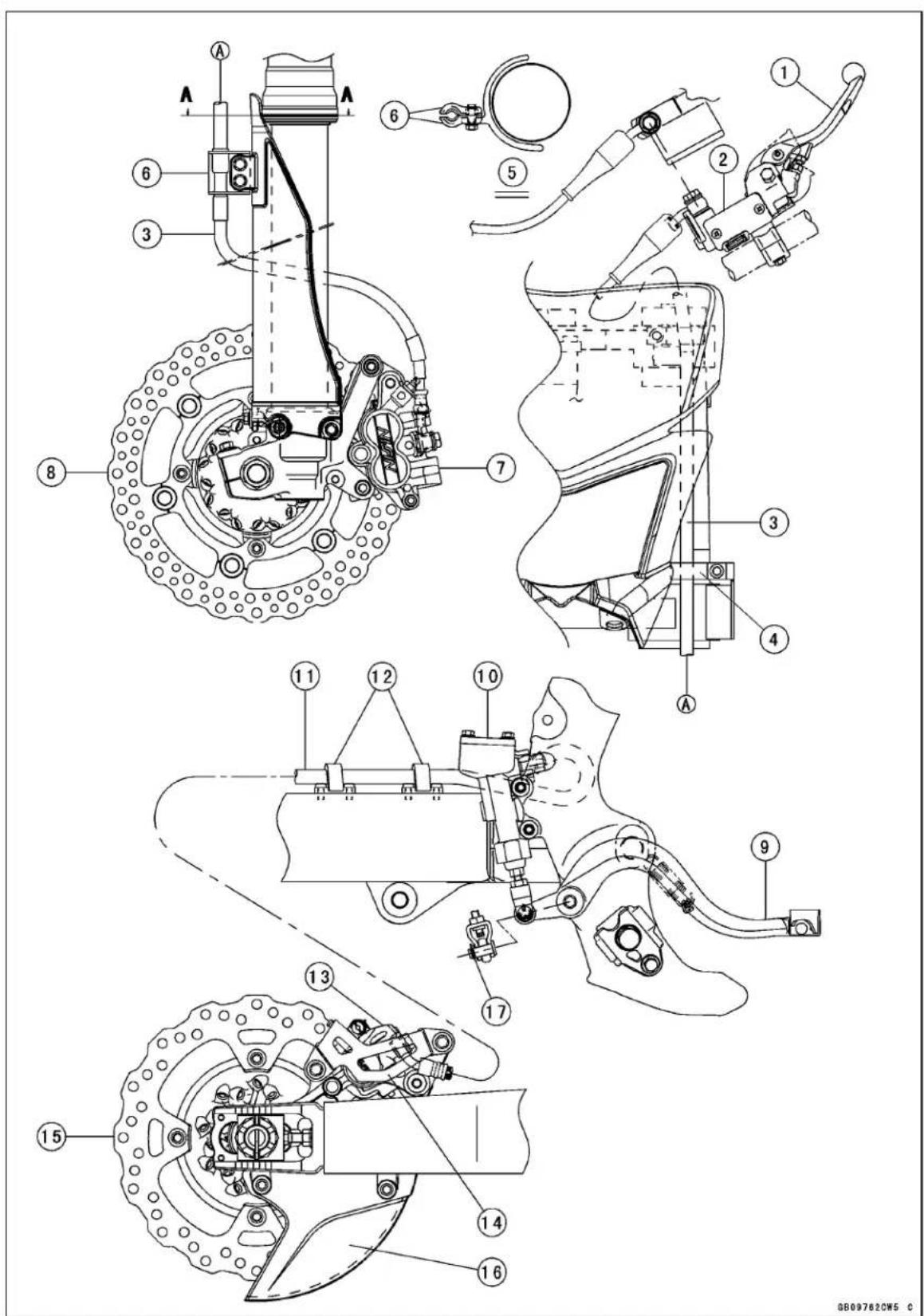
Cable, Wire, and Hose Routing
- Brake Lever
- Front Brake Master Cylinder
- Front Brake Hose
- Clamp
- View from A-A
- Clamps
- Front Brake Caliper
- Front Brake Disc
- Brake Pedal
- Rear Brake Master Cylinder
- Rear Brake Hose
- Clamps
- Rear Brake Caliper
- Rear Brake Caliper Guard
- Rear Brake Disc
- Rear Brake Disc Guard
- Cotter Pin
17-16 APPENDIX
Cable, Wire, and Hose Routing
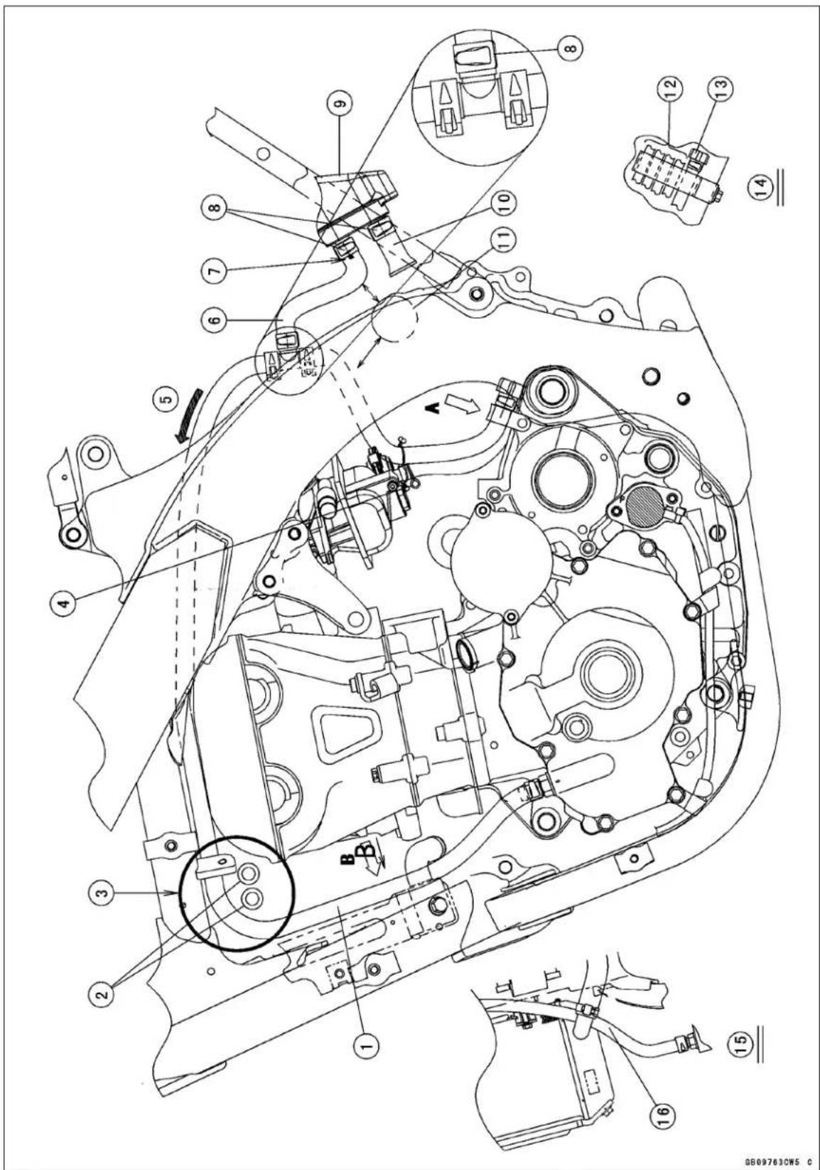
Cable, Wire, and Hose Routing
- Breather Hose
- Fuel Hoses
- Run the breather hose over the fuel hoses.
- Clamp
- Stretch to the arrow mark without loosing the hose when mounting the fuel tank. (Keep the gap of the chain guide roller and hoses)
- Breather Hose
- Face the painted portion to left side.
- Clamps (Face the tabs to left side.)
- Air Cleaner Housing
- Boot (Install the boot as shown in the figure.)
- Chain Guide Roller
- Vent Hoses
- Drain Hose (Run the drain hose leftmost of the bracket.)
- View from A
- View from B
- Run the breather hose under the radiator fitting.
17-18 APPENDIX
Cable, Wire, and Hose Routing
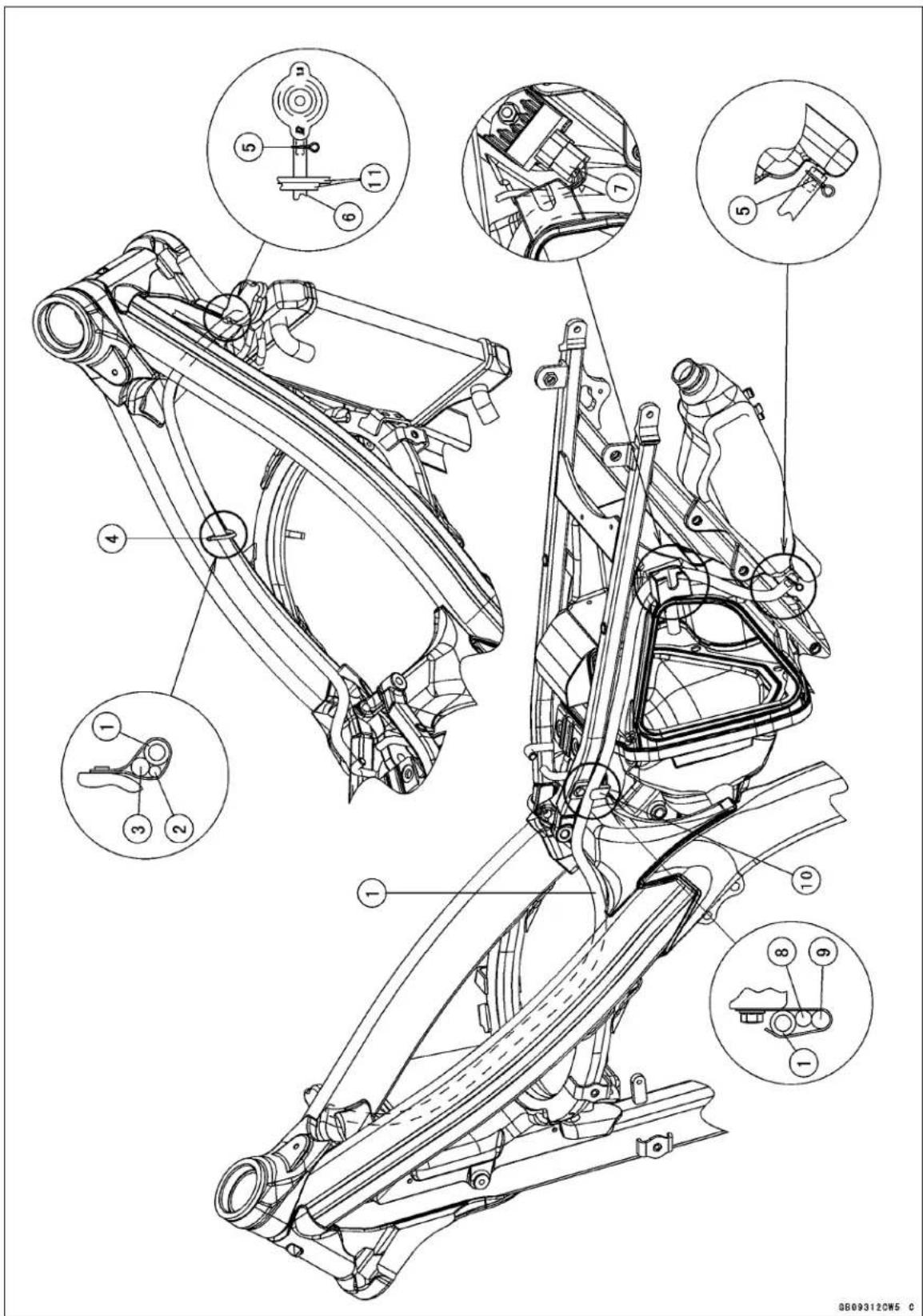
Cable, Wire, and Hose Routing
- Reserve Tank Hose
- Hot Starter Cable
- Clutch Cable
- Clamp
- Clamps
- Run the reserve tank hose under the throttle cables and main harness.
- Regulator/Rectifier Lead Connector (Green)
- Starter Motor Cable (White)
- Main Harness
- Clamp
- Throttle Cables
Cable, Wire, and Hose Routing
U.S.A., California and Canada Models
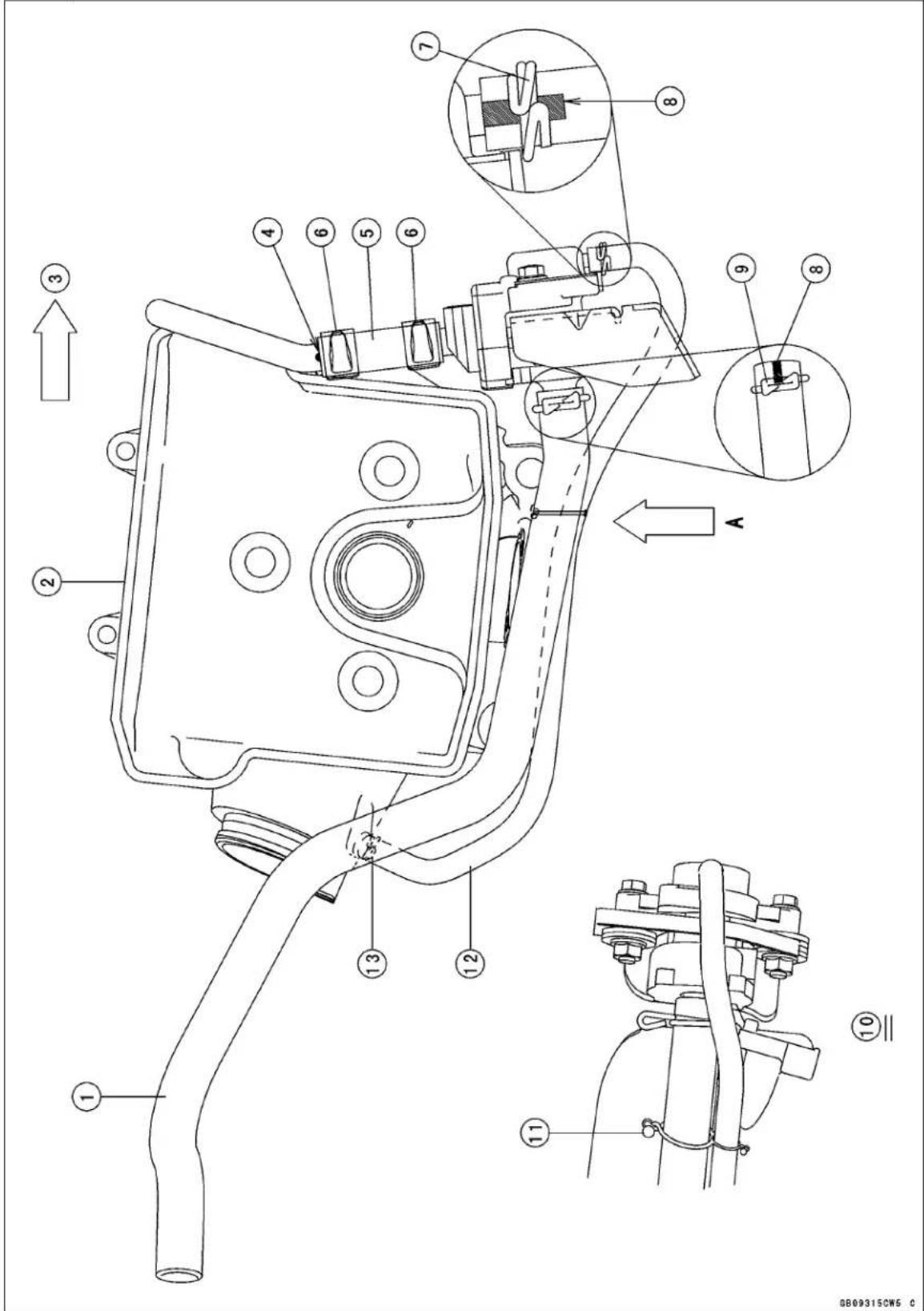
Cable, Wire, and Hose Routing
- Vacuum Switch Valve Hose
- Cylinder Head Cover
- Front of the engine
- White paint
- Insert the vacuum switch valve hose to the white painted portion of the pipe.
- Clamps (Face the tabs to the upper of the engine.)
- Clamp (Face the tab to the upper of the engine.)
- Face the white painted portion to the upper of the engine.
- Clamp (Face the tab to the upper of the engine.)
- View from A
- Clamp (Install the clamp as shown in the figure.)
- Vacuum Hose
- Clamp (Face the tab to the upper of the engine.)
17-22 APPENDIX
Cable, Wire, and Hose Routing
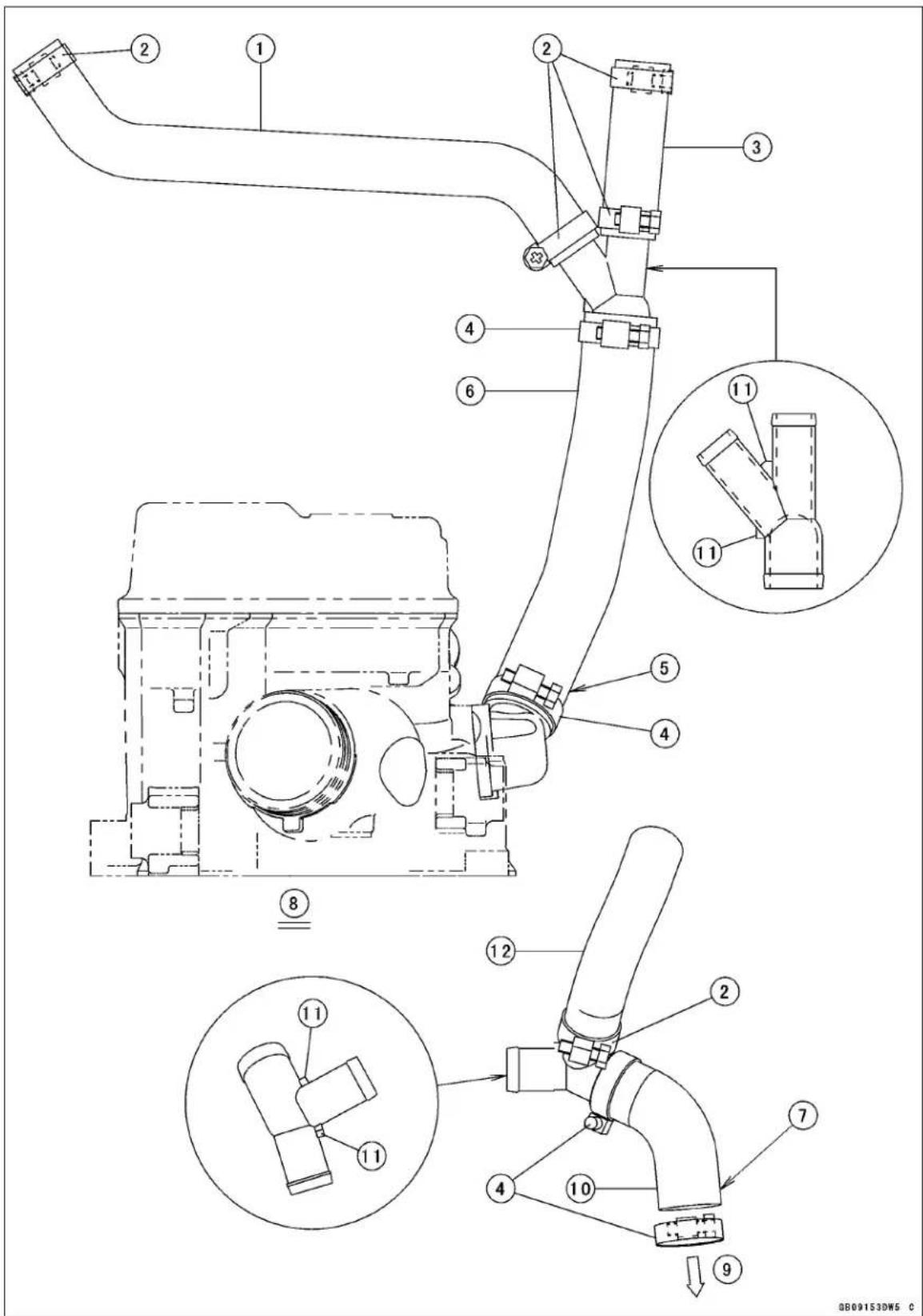
Cable, Wire, and Hose Routing
- Radiator Hose
- Clamps (Install the clamp as shown in the figure.)
- Radiator Hose
- Clamps (Install the clamp as shown in the figure.)
- Face the white painted portion to the right side of the engine.
- Water hose
- Face the white painted portion to the right side of the engine.
- View from the rear side of the engine.
- To Water Pump Cover
- Water Hose
- Stoppers
- Radiator Hose
17-24 APPENDIX
Cable, Wire, and Hose Routing
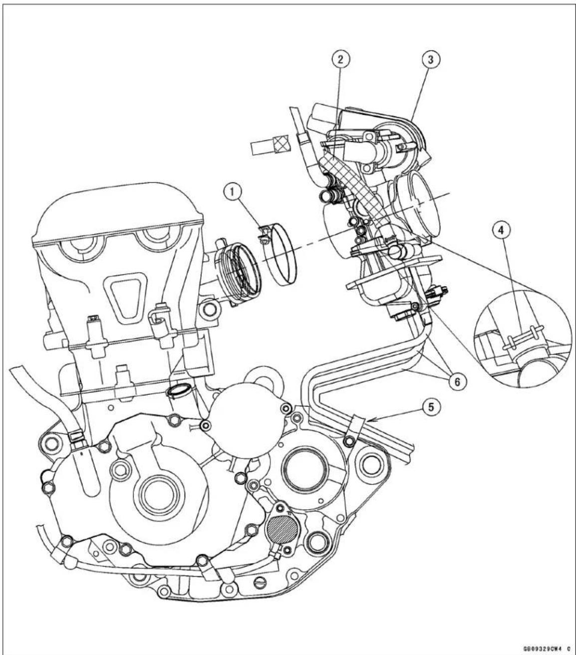
- Clamp (Install the clamp as shown in the figure.)
- Fuel Hose
- Carburetor
- Clamp (Install the clamp as shown in the figure.)
- Clamp (Run the vent hoses through the clamp on the backward of the crankcase.)
- Vent Hoses
Troubleshooting Guide
This is not an exhaustive list, giving every possible cause for each problem listed. it is meant simply as a rough guide to assist the troubleshooting for some of the more common difficulties.
Engine Doesn't Start, Starting Difficulty:
Starter motor not rotating:
Starter lockout switch trouble
Starter motor trouble
Battery voltage low
Starter relay not contacting or operating
Starter button not contacting
Wiring open or shorted
Engine stop switch trouble
Fuse blown
Starter motor rotating but engine doesn't turn over:
Starter clutch trouble
Engine won't turn over:
Valve seizure
Connecting rod small end, big end seizure
Transmission gear or bearing seizure
Camshaft seizure
Starter idle gear seizure
Kick shaft return spring broken
Kick ratchet gear not engaging
No fuel flow:
No fuel in tank
Fuel tank cap air vent obstructed
Fuel tap clogged
Fuel tap turned off
Fuel line clogged
Carburetor float valve clogged
Engine flooded:
Fuel level in carburetor float bowl too high
Float valve worn or jammed with foreign matter
Starting technique faulty (When flooded, crank the engine with the hot start opened to allow more air to reach the engine.)
Fuel/air mixture incorrect:
Pilot screw and/or idle adjusting screw mal-adjusted
Pilot jet or air passage clogged
Air cleaner clogged, poorly sealed, or missing
Starter jet clogged
No spark; spark weak:
Spark plug dirty, broken, or gap maladjusted
Spark plug cap or high tension wiring trouble
Spark plug cap shorted or not in good contact
Spark plug incorrect heat value
Faulty IC igniter
Crankshaft sensor trouble
Ignition coil trouble
Engine stop switch shorted
Neutral switch trouble
Wiring shorted or open
Flywheel damage
Compression Low:
Spark plug loose
Cylinder head not sufficiently tightened down
No valve clearance
Cylinder, piston worn
Piston ring bad (worn, weak, broken, or sticking)
Piston ring/groove clearance excessive
Cylinder head gasket damaged
Cylinder head warped
Valve spring broken or weak
Valve not seating properly (valve bent, deformed, worn, or carbon accumulation on the seating surface)
Decompression trouble
Poor Running at Low Speed:
Spark weak:
Battery voltage low
Spark plug dirty, broken, or gap maladjusted
Spark plug cap or high tension wiring trouble
Spark plug cap shorted or not in good contact
Spark plug incorrect heat value
Faulty IC igniter
Crankshaft sensor trouble
Flywheel damaged
Ignition coil trouble
Wiring connector not in good contact
Fuel/air mixture incorrect:
Pilot screw maladjusted
Pilot jet, or air passage clogged
Needle Jet, or air passage clogged
Air cleaner clogged, poorly sealed, or missing
Starter plunger stuck open
Hot start stuck open
Fuel level in carburetor float bowl too high or too low
Fuel tank cap air vent obstructed
Fuel tap clogged
Carburetor holder loose
Air cleaner duct loose
Troubleshooting Guide
Compression low:
Spark plug loose
Cylinder head not sufficiently tightened down
No valve clearance
Cylinder, piston worn
Piston ring bad (worn, weak, broken, or sticking)
Piston ring/groove clearance excessive
Cylinder head gasket damaged
Cylinder head warped
Valve spring broken or weak
Valve not seating properly (valve bent, deformed, worn, or carbon accumulation on the seating surface)
Decompression trouble
Other:
Faulty IC igniter
Engine oil level to high
Engine oil viscosity too high
Brake dragging
Drive train trouble
Engine overheating
Clutch slipping
Vacuum Switch Valve trouble (equipped models)
Poor Running or No Power at High Speed:
Firing incorrect:
Spark plug dirty, broken, or gap maladjusted
Spark plug cap or high tension wiring trouble
Spark plug cap shorted or not in good contact
Spark plug incorrect heat value
Faulty IC igniter
Crankshaft sensor trouble
Flywheel damage
Ignition coil trouble
Wiring connector not in good contact
Fuel/air mixture incorrect:
Starter plunger stuck open
Hot start stuck open
Main jet clogged or wrong size
Jet needle or needle jet worn
Air jet clogged
Fuel level in carburetor float bowl too high or too low
Needle Jet, or air passage clogged
Air cleaner clogged, poorly sealed, or missing
Air cleaner duct loose
Water or foreign matter in fuel
Carburetor holder loose
Fuel tank cap air vent obstructed
Fuel tap clogged
Fuel line clogged
Compression low:
Spark plug loose
Cylinder head not sufficiently tightened down
No valve clearance
Cylinder, piston worn
Piston ring bad (worn, weak, broken, or sticking)
Piston ring/groove clearance excessive
Cylinder head gasket damaged
Cylinder head warped
Valve spring broken or weak
Valve not seating properly (valve bent, deformed, worn, carbon accumulation on the seating surface.)
Decompression trouble
Knocking:
Carbon built up in combustion chamber
Fuel poor quality or incorrect
Spark plug incorrect heat valve
Faulty IC igniter
Crankshaft Sensor trouble
Other:
Throttle valve won't fully open
Brake dragging
Air cleaner clogged
Water or foreign matter in fuel
Clutch slipping
Overheating
Engine oil level too high
Engine oil viscosity too high
Drive train trouble
Crankshaft bearing worn or damage
Vacuum Switch Valve trouble (equipped models)
Engine Overheating:
Firing incorrect:
Spark plug dirty, broken, or maladjusted
Spark plug incorrect
Faulty IC igniter
Fuel/air mixture incorrect:
Main jet clogged or wrong size
Fuel level in carburetor float bowl too low
Carburetor holder loose
Air cleaner clogged, poorly sealed, or missing
Air cleaner duct loose
Hot start stuck open
Compression high:
Carbon built up in combustion chamber
Engine load faulty:
Clutch slipping
Engine oil level too high
Engine oil viscosity too high
Troubleshooting Guide
Brake dragging
Drive train trouble
Lubrication inadequate:
Engine oil level too low
Engine oil poor quality or incorrect
Coolant incorrect:
Coolant level too low
Coolant deteriorated
Cooling system component incorrect:
Radiator clogged
Radiator cap trouble
Water pump not rotating
Water pump impeller damaged
Clutch Operation Faulty:
Clutch slipping:
No clutch lever play
Clutch cable maladjusted
Clutch inner cable sticking
Friction plate worn or warped
Steel plate worn or warped
Clutch spring broken or weak
Clutch release function trouble
Clutch hub or housing unevenly worn
Clutch not disengaging properly:
Clutch lever play excessive
Clutch spring compression uneven
Engine oil deteriorated
Engine oil viscosity too high
Engine oil level too high
Clutch housing seized
Clutch release function trouble
Clutch hub nut loose
Clutch plate warped or rough
Clutch hub spline damaged
Gear Shifting Faulty:
Doesn't go into gear; shift pedal doesn't
return:
Clutch not disengaging
Shift fork bent, worn, or seized
Shift return spring pin loose
Shift return spring weak or broken
Shift shaft lever broken
Pawl guide plate broken
Shift pawl broken
Shift pawl spring tension lose
Gear seized
Gear set lever operation trouble
Shift drum broken
Jumps out of gear:
Shift fork ear worn, bent
Gear groove worn
Gear dogs and/or dog holes worn
Shift drum groove worn
Gear set lever spring weak or broken
Shift fork guide pin worn
Drive shaft, output shaft, and/or gear splines worn
Overshifts:
Gear set lever spring weak or broken
Pawl guide plate worn
Abnormal Engine Noise:
Knocking:
Faulty IC igniter
Carbon built up in combustion chamber
Fuel poor quality or incorrect
Spark plug incorrect heat value
Overheating
Piston slap:
Cylinder/piston clearance excessive
Cylinder, piston worn
Connecting rod bent
Piston pin, piston pin hole worn
Valve noise:
Valve clearance incorrect
Valve spring broken or weak
Camshaft bearing or cam face worn
Valve lifter worn
Other noise:
Connecting rod big end, small end clearance excessive
Piston ring worn, broken, or stuck
Piston seizure, damage
Cylinder head gasket leaking
Exhaust pipe leaking at cylinder head connection
Crankshaft runout excessive
Engine mounts loose
Crankshaft bearing worn
Camshaft chain tensioner trouble
Camshaft chain, sprocket, chain guide worn
Primary gear worn or damaged
Decompressor spring broken
Magneto flywheel loose
Vacuum switch valve damaged (equipped models)
Abnormal Drive Train Noise:
Clutch noise:
Clutch housing finger and friction plate tang worn
Clutch housing gear worn
Metal chips jammed in clutch housing gear teeth
Transmission noise:
Bearings worn
Transmission gears worn or chipped
Metal chips jammed in gear teeth
Engine oil insufficient, low viscosity
Kick ratchet gear not properly disengaging from kick gear
Kick shaft idle gear worn or chipped
Troubleshooting Guide
Drive chain noise:
Drive chain maladjusted
Drive chain worn
Rear and/or engine sprocket worn
Drive chain lubrication insufficient
Rear wheel misaligned
Abnormal Frame Noise:
Front fork noise:
Oil insufficient or too thin
Spring weak or broken
Front fork air pressure high
Rear shock absorber noise:
Shock absorber trouble
Spring weak or broken
Disc brake noise:
Pad surface glazed
Disc warped
Caliper trouble
Pad installed incorrectly
Master cylinder damaged
Other noise:
Bracket, nut, bolt, etc., not properly mounted or tightened
Abnormal Exhaust Color:
White smoke:
Piston oil ring worn
Cylinder worn
Valve oil seal damaged
Valve guide worn
Engine oil level too high
Black smoke:
Air cleaner element clogged
Main jet too large or fallen off
Starter plunger stuck open
Fuel level in carburetor float bowl too high
Brown smoke:
Main jet too small
Fuel level in carburetor float bowl too low
Air cleaner duct loose
Air cleaner poorly sealed or missing
Handling and/or Stability
Unsatisfactory:
Handlebar hard to turn:
Cable, hose, wire routing incorrect
Steering stem nut too tight
Steering stem bearing damaged
Steering stem bearing lubrication inadequate
Steering stem bent
Tire air pressure too low
Handlebar shakes or excessively vibrates:
Tire worn
Swingarm pivot bearings worn
Rim warped, or not balanced
Spokes loose
Wheel bearing worn
Handlebar holder bolt loose
Steering stem head nut loose
Front, rear axle runout excessive
Handlebar pulls to one side:
Frame bent
Rear wheel misalignment
Swingarm bent or twisted
Swingarm pivot shaft bent
Steering maladjusted
Steering stem bent
Front fork bent
Right and left front fork oil level uneven
Suspension operation trouble:
(Too hard)
Tire air pressure too high
Front fork oil excessive
Front fork oil viscosity too high
Rear shock absorber adjustment too hard
Front fork bent
Front fork air pressure too high
(Too soft)
Front fork oil insufficient or leaking
Front fork oil viscosity too low
Rear shock absorber adjusted too soft
Front fork, rear shock absorber spring weak
Rear shock absorber oil or gas leaking
Tire air pressure too low
Brake Doesn't Hold:
Air in brake system
Pad, disc worn
Brake fluid leakage
Contaminated pad
Brake fluid deteriorated
Brake master cylinder cups damaged
Master cylinder scratched inside
Disc warped
Battery Trouble:
Battery discharged:
Charge insufficient
Battery faulty (too low terminal voltage)
Battery lead making poor contact
Load excessive (e.g., bulb of excessive wattage)
Magneto trouble
Wiring faulty
Regulator/rectifier trouble
Battery overcharged:
Magneto trouble
Regulator/rectifier trouble
Battery faulty
MODEL APPLICATION
| Year Model Beginning Frame No. | ||
| 2008 KLX | 450A8F | JKALXGA1□8A000001 or JKALX450AAA000001 |
| 2009 KLX | 450A9F | JKALXGA1□9A010001 or JKALX450AAA010001 |
| 2010 KLX | 450AAF | JKALXGA1□AA013001 or JKALX450AAA013001 |
| 2011 KLX | 450ABF | |
☐:This digit in the frame number changes from one machine to another.





- MOTORCYCLE SERVICE MANUAL
- QUICK REFERENCE GUIDE
- EMISSION CONTROL INFORMATION
- CRANKCASE EMISSION CONTROL SYSTEM
- EXHAUST EMISSION CONTROL SYSTEM
- EVAPORATIVE EMISSION CONTROL SYSTEM
- NOTE
- TAMPERING WITH NOISE CONTROL SYSTEM PROHIBITED
- FOREWORD
- HOW TO USE THIS MANUAL
- DANGER
- WARNING
- CAUTION
- NOTICE
- GENERAL INFORMATION
- TABLE OF CONTENTS
- BEFORE SERVICING
- BATTERY GROUND
- EDGES OF PARTS
- SOLVENT
- CLEANING VEHICLE BEFORE DISASSEMBLY
- ARRANGEMENT AND CLEANING OF REMOVED PARTS
- STORAGE OF REMOVED PARTS
- INSPECTION
- REPLACEMENT PARTS
- ASSEMBLY ORDER
- TIGHTENING SEQUENCE
- TIGHTENING TORQUE
- FORCE
- GASKET, O-RING
- LIQUID GASKET, NON-PERMANENT LOCKING AGENT
- PRESS
- BALL BEARING AND NEEDLE BEARING
- OIL SEAL, GREASE SEAL
- CIRCLIPS, COTTER PINS
- LUBRICATION
- DIRECTION OF ENGINE ROTATION
- ELECTRICAL LEADS
- INSTRUMENT
- MODEL IDENTIFICATION
- UNIT CONVERSION TABLE
- UNITS OF TEMPERATURE
- PERIODIC MAINTENANCE
- PERIODIC MAINTENANCE CHART
- TORQUE AND LOCKING AGENT
- SPECIAL TOOLS
- PERIODIC MAINTENANCE PROCEDURES
- FUEL SYSTEM
- FUEL HOSE AND CONNECTION INSPECTION
- THROTTLE GRIP FREE PLAY INSPECTION
- THROTTLE GRIP FREE PLAY
- THROTTLE GRIP FREE PLAY ADJUSTMENT
- HOT STARTER LEVER FREE PLAY INSPECTION
- IDLE SPEED INSPECTION
- IDLE SPEED ADJUSTMENT
- AIR CLEANER ELEMENT CLEANING AND INSPECTION
- FUEL INSPECTION
- FUEL TANK, FILTER AND TAP CLEANING
- FUEL TAP AND FILTER INSPECTION
- COOLING SYSTEM
- COOLANT LEVEL INSPECTION
- COOLANT DETERIORATION INSPECTION
- RADIATOR HOSES AND CONNECTIONS INSPECTION
- ENGINE TOP END
- VACUUM SWITCH VALVE TEST
- U.S.A., CALIFORNIA AND CANADA MODELS
- VALVE CLEARANCE INSPECTION
- VALVE CLEARANCE ADJUSTMENT
- EXAMPLE
- CYLINDER HEAD WARP INSPECTION
- CYLINDER WEAR INSPECTION
- PISTON/CYLINDER CLEARANCE
- PISTON, PISTON RING AND PISTON PIN REPLACEMENT
- SPARK ARRESTER CLEANING
- ENGINE RIGHT SIDE
- CLUTCH LEVER FREE PLAY CHECK
- CLUTCH LEVER FREE PLAY ADJUSTMENT
- FRICTION AND STEEL PLATES INSPECTION
- FRICTION PLATE THICKNESS
- FRICTION AND STEEL PLATES WARP
- ENGINE LUBRICATION SYSTEM
- ENGINE OIL CHANGE
- RECOMMENDED ENGINE
- OIL FILTER CHANGE
- BREATHER HOSE INSPECTION
- CRANKSHAFT/TRANSMISSION
- CRANKSHAFT INSPECTION
- CONNECTING ROD BIG END SIDE CLEARANCE
- WHEEL/TIRES
- AIR PRESSURE INSPECTION/ADJUSTMENT
- TIRES INSPECTION
- SPOKE TIGHTNESS INSPECTION
- RIM RUNOUT INSPECTION
- RIM RUNOUT (WITH TIRE INSTALLED)
- WHEEL BEARING INSPECTION
- FINAL DRIVE
- DRIVE CHAIN SLACK INSPECTION
- DRIVE CHAIN SLACK ADJUSTMENT
- DRIVE CHAIN WEAR INSPECTION
- DRIVE CHAIN LUBRICATION
- SPROCKET WEAR INSPECTION
- REAR SPROCKET WARP INSPECTION
- BRAKES
- BRAKE LEVER AND PEDAL POSITION ADJUSTMENT
- BRAKE FLUID LEVEL INSPECTION
- BRAKE FLUID CHANGE
- WHEN WORKING WITH THE DISC BRAKE, OBSERVE THE PRECAUTIONS LISTED BELOW
- BRAKE PAD WEAR INSPECTION
- BRAKE MASTER CYLINDER CUP AND DUST SEAL REPLACEMENT
- CALIPER PISTON SEAL AND DUST SEAL REPLACEMENT
- BRAKE HOSE AND CONNECTION CHECK
- BRAKE HOSE REPLACEMENT
- FOR FRONT BRAKE
- FOR REAR BRAKE
- SUSPENSION
- FRONT FORK INSPECTION
- FRONT FORK OIL CHANGE (EACH FORK LEG)
- REAR SHOCK ABSORBER INSPECTION
- REAR SHOCK ABSORBER OIL CHANGE
- SWINGARM AND UNI-TRAK LINKAGE INSPECTION
- SWINGARM AND UNI-TRACK LINKAGE PIVOT LUBRICATE
- STEERING
- STEERING INSPECTION
- STEERING ADJUSTMENT
- STEM BEARING LUBRICATION
- FRAME
- FRAME INSPECTION
- ELECTRICAL SYSTEM
- SPARK PLUG CLEANING AND INSPECTION
- CABLE INSPECTION
- POINTS: LUBRICATE WITH GREASE
- CABLES: LUBRICATE WITH RUST INHIBITOR
- NUT, BOLT, AND FASTENER TIGHTNESS INSPECTION TIGHTNESS INSPECTION
- NUT, BOLT AND FASTENER TO BE CHECKED
- EXPLODED VIEW
- SPECIAL TOOL
- THROTTLE GRIP AND CABLE
- FREE PLAY INSPECTION
- FREE PLAY ADJUSTMENT
- THROTTLE CABLE REPLACEMENT
- THROTTLE CABLE LUBRICATION
- THROTTLE CABLE INSPECTION
- HOT STARTER CABLE REMOVAL
- HOT STARTER CABLE INSTALLATION
- HOT STARTER LEVER FREE PLAY ADJUSTMENT
- HOT STARTER CABLE LUBRICATION
- HOT STARTER CABLE INSPECTION
- CARBURETOR
- SERVICE FUEL LEVEL INSPECTION
- SERVICE FUEL LEVEL ADJUSTMENT
- CARBURETOR REMOVAL
- CARBURETOR INSTALLATION
- CARBURETOR DISASSEMBLY
- CARBURETOR CLEANING
- CARBURETOR INSPECTION
- CARBURETOR ASSEMBLY
- AIR CLEANER
- AIR CLEANER HOUSING REMOVAL
- AIR CLEANER HOUSING INSTALLATION
- ELEMENT REMOVAL
- ELEMENT INSTALLATION
- ELEMENT CLEANING AND INSPECTION
- FUEL TANK
- FUEL TANK REMOVAL
- FUEL TANK INSTALLATION
- FUEL FILTER REMOVAL
- FUEL FILTER INSTALLATION
- COOLANT FLOW CHART
- COOLANT
- COOLANT DRAINING
- COOLANT FILLING
- AIR BLEEDING
- COOLING SYSTEM PRESSURE TESTING
- COOLING SYSTEM FLUSHING
- RESERVE TANK REMOVAL
- WATER PUMP
- WATER PUMP COVER REMOVAL
- WATER PUMP COVER INSTALLATION
- IMPELLER REMOVAL
- IMPELLER INSTALLATION
- WATER PUMP INSPECTION
- OIL SEAL AND BEARING REMOVAL
- OIL SEAL AND BEARING INSTALLATION
- RADIATOR
- RADIATOR REMOVAL
- RADIATOR INSTALLATION
- RADIATOR INSPECTION
- RADIATOR CAP INSPECTION
- FILLER NECK INSPECTION
- HOSE INSPECTION
- HOSE INSTALLATION
- SPECIFICATIONS
- SPECIAL TOOLS AND SEALANT
- CLEAN AIR SYSTEM (U.S.A., CALIFORNIA, AND CANADA MODELS)
- VACUUM SWITCH VALVE REMOVAL
- VACUUM SWITCH VALVE INSTALLATION
- CYLINDER HEAD COVER
- CYLINDER HEAD COVER REMOVAL
- CYLINDER HEAD COVER INSTALLATION
- CAMSHAFT CHAIN TENSIONER
- CAMSHAFT CHAIN TENSIONER REMOVAL
- CAMSHAFT CHAIN TENSIONER INSTALLATION
- CAMSHAFT
- CAMSHAFT REMOVAL
- CAMSHAFT INSTALLATION
- CAMSHAFT CHAIN REMOVAL
- CAMSHAFT CHAIN INSTALLATION
- CAMSHAFT AND CAMSHAFT CAP WEAR
- CAMSHAFT JOURNAL, CAMSHAFT CAP CLEARANCE
- CAMSHAFT JOURNAL DIAMETER
- CAMSHAFT RUNOUT
- CAM WEAR
- CAM HEIGHT
- CYLINDER HEAD
- CYLINDER COMPRESSION MEASUREMENT
- CYLINDER HEAD REMOVAL
- CYLINDER HEAD INSTALLATION
- CYLINDER HEAD CLEANING
- CYLINDER HEAD WARP
- VALVES
- VALVE REMOVAL
- VALVE INSTALLATION
- VALVE GUIDE REMOVAL
- VALVE GUIDE INSTALLATION
- VALVE/VALVE GUIDE CLEARANCE MEASUREMENT (WOBBLE METHOD)
- VALVE SEAT INSPECTION
- VALVE SEATING SURFACE OUTSIDE DIAMETER
- VALVE SEATING SURFACE WIDTH
- VALVE SEAT REPAIR
- SEAT CUTTER OPERATION CARE
- MARKS STAMPED ON THE CUTTER
- REPAIR OPERATING PROCEDURES
- THE 32° CUTTER REMOVES MATERIAL VERY QUICKLY. CHECK THE SEAT OUTSIDE DIAMETER FREQUENTLY TO PREVENT OVERGRINDING
- CYLINDER AND PISTON
- CYLINDER REMOVAL
- PISTON REMOVAL
- CYLINDER AND PISTON INSTALLATION
- CYLINDER WEAR
- PISTON WEAR
- PISTON RING/RING GROOVE CLEARANCE
- PISTON RING GROOVE WIDTH
- PISTON RING THICKNESS
- PISTON RING END GAP MEASUREMENT
- PISTON RING END GAP
- PISTON, PISTON PIN, CONNECTING ROD WEAR INSPECTION
- CARBURETOR HOLDER
- CARBURETOR HOLDER INSTALLATION
- TORQUE - CARBURETOR HOLDER CLAMP SCREWS: 2.0 N·M (0.20 KGF·M, 18 IN·LB)
- MUFFLER
- MUFFLER REMOVAL
- MUFFLER INSTALLATION
- EXHAUST SYSTEM INSPECTION
- CLUTCH LEVER AND CABLE
- CLUTCH LEVER FREE PLAY INSPECTION
- CLUTCH LEVER INSTALLATION
- CLUTCH CABLE REMOVAL
- CLUTCH CABLE INSTALLATION
- CLUTCH CABLE INSPECTION AND LUBRICATION
- CLUTCH COVER AND RIGHT ENGINE COVER
- CLUTCH COVER REMOVAL
- CLUTCH COVER INSTALLATION
- RIGHT ENGINE COVER REMOVAL
- RIGHT ENGINE COVER INSTALLATION
- RELEASE SHAFT REMOVAL
- RELEASE SHAFT INSTALLATION
- CLUTCH
- CLUTCH REMOVAL
- CLUTCH INSTALLATION
- PULL ROD POSITION
- CLUTCH PLATE ASSEMBLY FREE PLAY INSPECTION/ADJUSTMENT
- FRICTION AND STEEL PLATES WEAR, DAMAGE INSPECTION
- FRICTION AND STEEL PLATE WARP INSPECTION
- CLUTCH SPRING FREE LENGTH INSPECTION
- CLUTCH HOUSING FINGER DAMAGE
- FRICTION PLATE/CLUTCH HOUSING CLEARANCE
- CLUTCH HUB SPLINE DAMAGE
- PRIMARY GEAR
- PRIMARY GEAR REMOVAL
- PRIMARY GEAR INSTALLATION
- EXTERNAL SHIFT MECHANISM
- EXTERNAL SHIFT MECHANISM REMOVAL
- EXTERNAL SHIFT MECHANISM INSTALLATION
- EXTERNAL SHIFT MECHANISM INSPECTION
- KICK PEDAL ASSY REMOVAL
- KICK PEDAL ASSY INSTALLATION
- KICK PEDAL ASSY DISASSEMBLY
- KICK PEDAL ASSY ASSEMBLY
- IDLE GEAR REMOVAL
- KICKSTARTER
- IDLE GEAR INSTALLATION
- KICKSHAFT REMOVAL
- KICKSHAFT INSTALLATION
- KICK SHAFT ASSEMBLY DISASSEMBLY/ASSEMBLY
- LUBRICATION SYSTEM CHART
- ENGINE OIL AND OIL FILTER
- ENGINE OIL LEVEL INSPECTION
- RACING THE ENGINE BEFORE THE OIL REACHES EVERY PART CAN CAUSE ENGINE SEIZURE
- OIL SCREEN
- OIL SCREEN (SCAVENGE) REMOVAL
- OIL SCREEN (SCAVENGE) INSTALLATION
- OIL SCREEN (FEED) REMOVAL
- OIL SCREEN (FEED) INSTALLATION
- OIL SCREEN (SCAVENGE) CLEANING
- OIL SCREEN (FEED) CLEANING
- OIL PRESSURE RELIEF VALVE
- OIL PRESSURE RELIEF VALVE REMOVAL
- OIL PRESSURE RELIEF VALVE INSTALLATION
- OIL PRESSURE RELIEF VALVE INSPECTION
- OIL PUMP
- OIL PUMP (SCAVENGE) REMOVAL
- OIL PUMP (SCAVENGE) INSTALLATION
- OIL PUMP (FEED) REMOVAL
- OIL PUMP (FEED) INSTALLATION
- OIL PUMP INSPECTION
- OIL PRESSURE
- OIL PRESSURE MEASUREMENT
- ENGINE REMOVAL/INSTALLATION
- ENGINE REMOVAL
- ENGINE INSTALLATION
- CRANKCASE
- CRANKCASE DISASSEMBLY
- CRANKCASE ASSEMBLY
- CRANKSHAFT/CONNECTING ROD
- CRANKSHAFT REMOVAL
- CRANKSHAFT INSTALLATION
- CRANKSHAFT DISASSEMBLY
- CRANKSHAFT ASSEMBLY
- CONNECTING ROD BIG END RADIAL CLEARANCE
- CRANKSHAFT RUNOUT
- DO NOT HAMMER THE CRANK HALF AT THE POINT [B]
- CONNECTING ROD BIG END SEIZURE
- CONNECTING ROD BEND
- CONNECTING ROD TWIST
- TORQUE LIMITER
- TORQUE LIMITER REMOVAL/INSTALLATION
- TORQUE LIMITER INSPECTION
- TRANSMISSION
- TRANSMISSION SHAFT REMOVAL
- TRANSMISSION SHAFT INSTALLATION
- TRANSMISSION SHAFT DISASSEMBLY
- TRANSMISSION SHAFT ASSEMBLY
- SHIFT FORK BENDING
- SHIFT FORK/GEAR GROOVE WEAR
- SHIFT FORK GUIDE PIN/SHIFT DRUM GROOVE WEAR
- GEAR DAMAGE
- BALANCER
- BALANCER REMOVAL
- BALANCER INSTALLATION
- BEARINGS/OIL SEALS
- BEARING REPLACEMENT
- BEARING INSPECTION
- OIL SEAL INSPECTION
- WHEELS/TIRES
- WHEELS (RIMS)
- FRONT WHEEL REMOVAL
- FRONT WHEEL INSTALLATION
- REAR WHEEL REMOVAL
- REAR WHEEL INSTALLATION
- WHEELS INSPECTION
- AXLE INSPECTION
- TIRES
- TIRE REMOVAL
- TAKE CARE NOT TO INSET THE TIRE IRONS SO DEEPLY THAT THE TUBE GETS DAMAGED
- TIRE INSTALLATION
- HUB BEARINGS
- HUB BEARING REMOVAL
- HUB BEARING INSTALLATION
- HUB BEARING INSPECTION
- HUB BEARING LUBRICATION
- DRIVE CHAIN
- WHEEL ALIGNMENT INSPECTION
- WHEEL ALIGNMENT ADJUSTMENT
- DRIVE CHAIN REMOVAL
- DRIVE CHAIN INSTALLATION
- SPROCKETS
- ENGINE SPROCKET REMOVAL
- ENGINE SPROCKET INSTALLATION
- REAR SPROCKET REMOVAL
- REAR SPROCKET INSTALLATION
- BRAKE LEVER, BRAKE PEDAL
- BRAKE LEVER ADJUSTMENT
- BRAKE PEDAL POSITION ADJUSTMENT
- BRAKE PEDAL REMOVAL
- BRAKE PEDAL INSTALLATION
- BRAKE FLUID
- FLUID LEVEL INSPECTION
- FLUID CHANGE
- BLEEDING THE BRAKE LINE
- CALIPER
- CALIPER REMOVAL
- FRONT BRAKE
- REAR BRAKE
- CALIPER INSTALLATION
- CALIPER DISASSEMBLY
- FLUID SEAL DAMAGE
- DUST SEAL AND COVER DAMAGE
- PISTON CYLINDER DAMAGE
- CALIPER HOLDER SHAFT WEAR
- BRAKE PAD REMOVAL
- FRONT BRAKE PAD
- REAR BRAKE PAD
- BRAKE PAD INSTALLATION
- BRAKE PAD INSPECTION
- MASTER CYLINDER
- FRONT MASTER CYLINDER REMOVAL
- FRONT MASTER CYLINDER INSTALLATION
- REAR MASTER CYLINDER REMOVAL
- REAR MASTER CYLINDER INSTALLATION
- FRONT MASTER CYLINDER DISASSEMBLY
- REAR MASTER CYLINDER DISASSEMBLY
- MASTER CYLINDER ASSEMBLY
- MASTER CYLINDER INSPECTION (VISUAL INSPECTION)
- BRAKE DISK
- BRAKE DISC REMOVAL
- BRAKE DISC INSTALLATION
- BRAKE DISCLNSPECTION
- THICKNESS
- RUNOUT
- BRAKE HOSE
- BRAKE HOSE REMOVAL/INSTALLATION
- BRAKE HOSE INSPECTION
- FRONT FORK
- AIR PRESSURE
- REBOUND DAMPING ADJUSTMENT
- COMPRESSION DAMPING ADJUSTMENT
- COMPRESSION DAMPING ADJUSTER SETTING
- OIL CHANGE (EACH FORK LEG)
- FRONT FORK REMOVAL
- FRONT FORK INSTALLATION
- FRONT FORK DISASSEMBLY (EACH FORK LEG)
- FRONT FORK ASSEMBLY
- ADJUSTER ASSEMBLY INSPECTION
- BASE VALVE ASSEMBLY INSPECTION
- CYLINDER UNIT INSPECTION
- INNER TUBE INSPECTION
- GUIDE BUSH INSPECTION
- DUST SEAL/OIL SEAL INSPECTION
- SPRING TENSION
- REAR SUSPENSION (UNI-TRAK)
- REAR SHOCK ABSORBER
- REBOUND DAMPING ADJUSTER SETTING
- SPRING PRELOAD ADJUSTMENT
- REAR SHOCK ABSORBER REMOVAL
- WHEN PULLING OUT THE MOUNTING BOLTS, LIFT THE REAR WHEEL SLIGHTLY. FORCING OR TAPPING ON A BOLT COULD DAMAGE THE BOLT, SLEEVE, AND BEARING
- REAR SHOCK ABSORBER INSTALLATION
- SPRING REPLACEMENT
- REAR SHOCK ABSORBER DISASSEMBLY (OIL CHANGE)
- REAR SHOCK ABSORBER ASSEMBLY
- REAR SHOCK ABSORBER SCRAPPING
- SWINGARM
- SWINGARM REMOVAL
- SWINGARM INSTALLATION
- SWINGARM BEARING REMOVAL
- SWINGARM BEARING INSTALLATION
- SPECIAL TOOL - BEARING DRIVER SET: 57001-1129
- SWINGARM BEARING, SLEEVE INSPECTION
- DRIVE CHAIN GUIDE, GUIDE ROLLER, CHAIN SLIPPER WEAR
- TIE-ROD, ROCKER ARM
- TIE-ROD REMOVAL
- TIE-ROD INSTALLATION
- ROCKER ARM REMOVAL
- ROCKER ARM INSTALLATION
- TIE-ROD AND ROCKER ARM BEARING REMOVAL
- TIE-ROD AND ROCKER ARM BEARING INSTALLATION
- NEEDLE BEARING INSPECTION
- UNI-TRAK MAINTENANCE
- UNI-TRAK LINKAGE INSPECTION
- TIE-ROD AND ROCKER ARM SLEEVE WEAR
- SLEEVE OUTSIDE DIAMETER
- TIE-ROD AND ROCKER ARM MOUNTING BOLT BEND
- STEERING STEM, STEM BEARING REMOVAL
- STEERING STEM, STEM BEARING INSTALLATION
- STEM BEARING WEAR, DAMAGE
- STEM WARP
- HANDLEBAR
- HANDLEBAR REMOVAL
- HANDLEBAR INSTALLATION
- REAR FRAME REMOVAL
- REAR FRAME INSTALLATION
- ENGINE GUARD INSTALLATION
- SEAT
- SEAT REMOVAL
- SEAT INSTALLATION
- SIDE COVER
- RIGHT SIDE COVER REMOVAL
- RIGHT SIDE COVER INSTALLATION
- LEFT SIDE COVER REMOVAL
- LEFT SIDE COVER INSTALLATION
- FENDER
- FRONT FENDER REMOVAL
- REAR FENDER REMOVAL
- REAR FLAP REMOVAL
- REFLECTOR INSTALLATION
- FOOTPEGS AND BRACKETS
- FOOTPEG REMOVAL
- FOOTPEGS INSTALLATION
- WIRING DIAGRAM (OTHER THAN AUSTRALIA MODELS)
- PRECAUTIONS
- ELECTRICAL WIRING
- WIRING INSPECTION
- BE SURE TO DISCONNECT THE NEGATIVE (−) CABLE FIRST
- BATTERY INSTALLATION
- BATTERY
- INTERCHANGE
- BATTERY DATE INSPECTION
- CHARGING CONDITION INSPECTION
- REFRESHING CHARGE
- FLYWHEEL MAGNETO
- MAGNETO COVER REMOVAL
- MAGNETO COVER INSTALLATION
- FLYWHEEL REMOVAL
- FLYWHEEL INSTALLATION
- STATOR REMOVAL
- STATOR INSTALLATION
- FLYWHEEL INSPECTION
- CHARGING VOLTAGE INSPECTION
- REGULATOR/RECTIFIER INSPECTION
- STARTER MOTOR CLUTCH
- STARTER MOTOR CLUTCH REMOVAL/INSTALLATION
- STARTER MOTOR CLUTCH INSPECTION
- STARTER MOTOR CLUTCH DISASSEMBLY
- STARTER MOTOR CLUTCH ASSEMBLY
- IGNITION TIMING
- IGNITION TIMING INSPECTION
- IGNITION SYSTEM
- CRANKSHAFT SENSOR REMOVAL
- CRANKSHAFT SENSOR INSTALLATION
- SAFETY INSTRUCTIONS
- IGNITION COIL REMOVAL
- IGNITION COIL INSPECTION
- MEASURING ARCING DISTANCE
- 3 NEEDLE ARCING DISTANCE
- MEASURING COIL RESISTANCE
- IGNITION COIL WINDING RESISTANCE
- SPARK PLUG GAP INSPECTION
- IGNITER REMOVAL
- IGNITER INSPECTION
- IGNITION COIL PRIMARY PEAK VOLTAGE CHECK
- CRANKSHAFT SENSOR PEAK VOLTAGE CHECK
- EXCITER COIL PEAK VOLTAGE CHECK
- THROTTLE POSITION SENSOR INSPECTION
- 1: 57001-1400
- THROTTLE POSITION SENSOR RESISTANCE INSPECTION
- THROTTLE POSITION SENSOR POSITION ADJUSTMENT
- CRANKSHAFT SENSOR INSPECTION
- ELECTRICAL STARTER SYSTEM
- STARTER MOTOR REMOVAL
- STARTER MOTOR INSTALLATION
- STARTER MOTOR DISASSEMBLY
- STARTER MOTOR ASSEMBLY
- CARBON BRUSH INSPECTION
- COMMUTATOR INSPECTION, CLEANING
- ARMATURE INSPECTION
- BRUSH LEAD INSPECTION
- TERMINAL BOLT INSPECTION
- STARTER RELAY INSPECTION
- LIGHTING SYSTEM
- HEADLIGHT AIMING INSPECTION
- HEADLIGHT BEAM VERTICAL ADJUSTMENT
- HEADLIGHT BULB REPLACEMENT
- HEADLIGHT REMOVAL/INSTALLATION
- TAIL LIGHT REMOVAL
- TAIL LIGHT INSTALLATION
- METER GAUGE
- METER UNIT REMOVAL/INSTALLATION
- METER UNIT DISASSEMBLY/ASSEMBLY
- SWITCH INSPECTION
- CLOCK SETTING
- LCD SEGMENT INSPECTION
- SWITCHES AND SENSORS
- SPEED SENSOR REMOVAL
- SPEED SENSOR INSTALLATION
- SPEED SENSOR INSPECTION
- THROTTLE POSITION SENSOR REMOVAL/INSTALLATION
- GEAR POSITION SWITCH REMOVAL
- GEAR POSITION SWITCH INSTALLATION
- GEAR POSITION SWITCH INSPECTION
- MAIN RELAY
- MAIN RELAY INSPECTION
- MAIN FUSE 20 A INSPECTION
- APPENDIX
- CABLE, WIRE, AND HOSE ROUTING
- TROUBLESHOOTING GUIDE
- ENGINE DOESN'T START, STARTING DIFFICULTY
- STARTER MOTOR NOT ROTATING
- STARTER MOTOR ROTATING BUT ENGINE DOESN'T TURN OVER
- ENGINE WON'T TURN OVER
- NO FUEL FLOW
- ENGINE FLOODED
- FUEL/AIR MIXTURE INCORRECT
- NO SPARK; SPARK WEAK
- COMPRESSION LOW
- POOR RUNNING AT LOW SPEED
- SPARK WEAK
- OTHER
- POOR RUNNING OR NO POWER AT HIGH SPEED
- FIRING INCORRECT
- KNOCKING
- ENGINE OVERHEATING
- COMPRESSION HIGH
- ENGINE LOAD FAULTY
- LUBRICATION INADEQUATE
- COOLANT INCORRECT
- COOLING SYSTEM COMPONENT INCORRECT
- CLUTCH OPERATION FAULTY
- CLUTCH SLIPPING
- CLUTCH NOT DISENGAGING PROPERLY
- GEAR SHIFTING FAULTY
- DOESN'T GO INTO GEAR; SHIFT PEDAL DOESN'T
- RETURN
- JUMPS OUT OF GEAR
- OVERSHIFTS
- ABNORMAL ENGINE NOISE
- PISTON SLAP
- VALVE NOISE
- OTHER NOISE
- ABNORMAL DRIVE TRAIN NOISE
- CLUTCH NOISE
- TRANSMISSION NOISE
- DRIVE CHAIN NOISE
- ABNORMAL FRAME NOISE
- FRONT FORK NOISE
- REAR SHOCK ABSORBER NOISE
- DISC BRAKE NOISE
- ABNORMAL EXHAUST COLOR
- WHITE SMOKE
- BLACK SMOKE
- BROWN SMOKE
- HANDLING AND/OR STABILITY
- UNSATISFACTORY
- HANDLEBAR HARD TO TURN
- HANDLEBAR SHAKES OR EXCESSIVELY VIBRATES
- HANDLEBAR PULLS TO ONE SIDE
- SUSPENSION OPERATION TROUBLE
- (TOO HARD)
- (TOO SOFT)
- BRAKE DOESN'T HOLD
- BATTERY TROUBLE
- BATTERY DISCHARGED
- BATTERY OVERCHARGED
Brand : KAWASAKI
Model : KLX450R (2011)
Category : Bicycle