
A9UW56GFA0 - Air-conditioner LG - Free user manual and instructions
Find the device manual for free A9UW56GFA0 LG in PDF.


User questions about A9UW56GFA0 LG
0 question about this device. Answer the ones you know or ask your own.
Ask a new question about this device
Download the instructions for your Air-conditioner in PDF format for free! Find your manual A9UW56GFA0 - LG and take your electronic device back in hand. On this page are published all the documents necessary for the use of your device. A9UW56GFA0 by LG.
USER MANUAL A9UW56GFA0 LG
Please read this installation manual completely before installing the product.
Installation work must be performed in accordance with the national wiring standards by authorized personnel only.
Please retain this installation manual for future reference after reading it thoroughly.
MULTI
TIPS FOR SAVING ENERGY
Here are some tips that will help you minimize the power consumption when you use the air conditioner. You can use your air conditioner more efficiently by referring to the instructions below:
- Do not cool excessively indoors. This may be harmful to your health and may consume more electricity.
- Block sunlight with blinds or curtains while you are operating the air conditioner.
- Keep doors or windows closed tightly while you are operating the air conditioner.
- Adjust the direction of the air flow vertically or horizontally to circulate indoor air.
- Speed up the fan to cool or warm indoor air quickly, in a short period of time.
- Open windows regularly for ventilation as the indoor air quality may deteriorate if the air conditioner is used for many hours.
- Clean the air filter once every 2 weeks. Dust and impurities collected in the air filter may block the air flow or weaken the cooling / dehumidifying functions.
For your records
Staple your receipt to this page in case you need it to prove the date of purchase or for warranty purposes. Write the model number and the serial number here:
Model number :
Serial number :
You can find them labeled on the side of each unit.
Dealer's name :
Date of purchase :
IMPORTANT SAFETY INSTRUCTIONS
READ ALL INSTRUCTIONS BEFORE USING THE APPLIANCE.
Always comply with the following precautions to avoid dangerous situations and ensure peak performance of your product

WARNING
It can result in serious injury or death when the directions are ignored

CAUTION
It can result in minor injury or product damage when the directions are ignored

WARNING
- Installation or repairs made by unqualified persons can result in hazards to you and others.
- Installation work must be performed in accordance with the National Electric Code by qualified and authorized personnel only.
- The information contained in the manual is intended for use by a qualified service technician familiar with safety procedures and equipped with the proper tools and test instruments.
- Failure to carefully read and follow all instructions in this manual can result in equipment malfunction, property damage, personal injury and/or death.
Installation
- Do not use a defective or underrated circuit breaker.
- Use the correctly rated breaker and fuse. There is risk of fire or electric shock.
- For electrical work, contact the dealer, seller, a qualified electrician, or an Authorized Service Center.
- Do not disassemble or repair the product by yourself. There is risk of fire or electric shock.
- Always ground the product as per the wiring diagram. - Do not connect the ground wire to gas or water pipes lightening rod or telephone ground wire. There is risk of fire or electric shock.
- Install the panel and the cover of control box securely. - There is risk of fire or electric shock due to dust, water etc.
- Use the correctly rated breaker or fuse.
- There is risk of fire or electric shock.
- Do not modify or extend the power cable. - If the power cable or cord has scrathes or skin peeled off or deteriorated then it must be replaced. There is risk of fire or electric shock.
- For installation, removal or reinstall, always contact the dealer or an Authorized Service Center.
- There is risk of fire, electric shock, explosion, or injury.
- Do not install the product on a defective installation stand. - Be sure that the installation area does not deteriorate with age. It may cause product to fall.
- Never install the outdoor unit on a moving base or a place from where it can fall down. - The falling outdoor unit can cause damage or injury or even death of a person.
- In outdoor unit the step-up capacitor supplies high voltage electricity to the electrical components.
- Be sure to discharge the capacitor completely before conducting the repair work. An charged capacitor can cause electrical shock.
- When installing the unit, use the installation kit provided with the product.
- Otherwise the unit may fall and cause severe injury.
- Indoor/outdoor wiring connections must be secured tightly and the cable should be routed properly so that there is no force pulling the cable from the connection terminals. - Improper or loose connections can cause heat generation or fire.
- Safely dispose off the packing materials. - Like screws, nails, batteries, broken things etc after installation or svc and then tear away and throw away the plastic packaging bags. Children may play with them and cause injury.
- Be sure to check the refrigerant to be used.
- Please read the label on the product. Incorrect refrigerant used can prevent the normal operation of the unit.
Operation
- When the product is soaked (flooded or submerged) in water, contact an Authorized Service Center for repair before using it again.
- There is risk of fire or eletric shock.
- Be sure to use only those parts which are listed in the svc parts list.
- Never attempt to modify the equipment. The use of inappropriate parts can cause an electrical shock, excessive heat generation or fire.
- Do not touch, operate, or repair the product with wet hands.
- Hold the plug by hand when taking out. There is risk of electric shock or fire.
- Do not place a heater or other heating appliances near the power cable.
- There is risk of fire and electric shock
- Do not allow water to run into electric parts.
- Install the unit away from water sources. There is risk of fire, failure of the product, or electric shock.
- Do not store or use or even allow flammable gas or combustibles near the product.
- There is risk of fire.
- Do not use the product in a tightly closed space for a long time.
- Perform ventilation regularly. Oxygen deficiency could occur and hence harm your health.
- Do not open the front grille of the product during operation.
- (Do not touch the electrostatic filter, if the unit is so equipped.) There is risk of physical injury, electric shock, or product failure.
- If strange sound, smell or smoke comes from product. Immediately turn the breaker off or disconnect the power supply cable.
- There is risk of electric shock or fire.
- Ventilate the product room from time to time when operating it together with a stove, or heating element etc.
- Oxygen deficiency can occur and hence harm your health.
- When the product is not to be used for a long time, disconnect the power supply plug or turn off the breaker.
- There is risk of product damage or failure, or unintended operation.
• Take care to ensure that nobody especially kids could step on or fall onto the outdoor unit. - This could result in personal injury and product damage.
• Take care to ensure that power cable could not be pulled out or damaged during operation. - There is risk of fire or electric shock.
- Do not place ANYTHING on the power cable.
- There is risk of fire or electric shock.
- When flammable gas leaks, turn off the gas and open a window for ventilation before turning on the product.
- Do not use the telephone or turn switches on or off. There is risk of explosion or fire.

CAUTION
Installation
- Two or more people must lift and transport the product.
- Avoid personal injury.
- Do not install the product where it will be exposed to sea wind (salt spray) directly.
- It may cause corrosion on the product.
• Install the drain hose to ensure that the condensed water is drained away properly. - A bad connection may cause water leakage.
- Keep level even when installing the product.
- To avoid vibration or noise.
- Do not install the product where the noise or hot air from the outdoor unit could damage or disturb the neighborhoods.
- It may cause a problem for your neighbors and hence dispute.
• Always check for gas (refrigerant) leakage after installation or repair of product. - Low refrigerant levels may cause failure of product.
- Contact the authorized service technician for repair or maintenance of this unit.
- Contact the installer for installation of this unit.
- When the power cord is to be replaced, replacement work shall be performed by authorized personnel only using only genuine replacement parts.
- Installation work must be performed in accordance with the National Electric Code by qualified and authorized personnel only.
- The user must carry out checks and cleaning of routine to avoid defective performance.
- In a special situation, only service personnel can carry out repair work.
Operation
- Do not use the product for special purposes, such as preserving foods, works of art, etc.
- It is a consumer air conditioner, not a precision refrigeration system. There is risk of damage or loss of property.
- Do not block the inlet or outlet of air flow.
- It may cause product failure.
- Use a soft cloth to clean.
- Do not use harsh detergents, solvents or splashing water etc. There is risk of fire, electric shock, or damage to the plastic parts of the product.
- Do not touch the metal parts of the product when removing the air filter.
- There is risk of personal injury.
- Do not step on or put anything on the product.
- (outdoor units) There is risk of personal injury and failure of product.
• Always insert the filter securely after cleaning.
- Clean the filter every two weeks or more often if necessary. A dirty filter reduces the efficiency.
- Do not insert hands or other objects through the air inlet or outlet while the product is operating.
- There are sharp and moving parts that could cause personal injury.
- Be cautious when unpacking and installing the product.
- Sharp edges could cause injury.
- If the refrigerant gas leaks during the repair, do not touch the leakaing refrigerant gas.
- The refrigernat gas can cause frostbite (cold burn).
- Do not tilt the unit when removing or uninstalling it.
- The condensed water inside can spill.
- Do not mix air or gas other than the specified refrigerant used in the system.
- If air enters the refrigerant system, an excessively high pressure results, causing equipment damage or injury.
- If the refrigerant gas leaks during the installation, ventilate the area immediately.
- Otherwise it can be harmful for your health.
- Dismantling the unit, treatment of the refrigerant oil and eventual parts should be done in accordance with local and national standards.
- Replace the all batteries in the remote control with new ones of the same type.
- Do not mix old and new batteries or different types of batteries.
There is risk of fire or product failure.
- Do not recharge or disassemble the batteries.
- Do not dispose off batteries in a fire. They may burn or explode.
- If the liquid from the batteries gets onto your skin or clothes, wash it well with clean water.
- Do not use the remote if the batteries have leaked. The chemicals in batteries could cause burns or other health hazards.
- If you eat the liquid from the batteries, brush your teeth and see doctor.
- Do not use the remote if the batteries have leaked. The chemicals in batteries could cause burns or other health hazards.
- Do not let the air conditioner run for a long time when the humidity is very high and a door or a window is left open.
- Moisture may condense and wet or damage furniture.
- Do not expose your skin or kids or plants to the cool or hot air draft.
- This could harm to your health.
- Do not drink the water drained from the product.
- It is not sanitary and could cause serious health issues.
- Use a firm stool or ladder when cleaning, maintaining or repairing the product at an height.
- Be careful and avoid personal injury.
- The user must carry out checks and cleaning of routine to avoid defective performance.
- In a special situation, only service personnel can carry out repair work.
- Means for disconnection must be incorporated in the fixed wiring in accordance with the wiring rules.
- This appliance is not intended for use by persons (including children) with reduced physical, sensory or mental capabilities or lack of experience and knowledge, unless they have been given supervision or instruction concerning use of the appliance by a person responsible for their safety.
- Children should be supervised to ensure that they do not play with the appliance.
TABLE OF CONTENTS
2 TIPS FOR SAVING ENERGY
7 INSTALLATION
8 INSTALLATION OF INDOOR, OUTDOOR UNIT
8 Select the best location
9 Foundation for Installation
10 Piping length and elevation
11 Refrigerant charge
12 FLARING WORK AND CONNECTION OF PIPING
12 Flaring work
13 Connection of piping - Indoor
15 Connection of piping - Outdoor
18 Installation
19 Installation of The Main Unit
20 CONNECTING THE CABLE BETWEEN INDOOR UNIT AND OUTDOOR UNIT
20 Connect the cable to the Indoor unit
22 Connect the cable to the Outdoor unit
24 Connection of Wiring
25 CHECKING THE DRAINAGE AND FORMING THE PIPINGS
25 Checking the Drainage
26 Forming the Piping
27 AIR PURGING AND EVACUATION
27 Checking method
28 Evacuation
29 INSTALLATION PI485
30 TEST RUNNING
31 FUNCTION
31 DIP S/W Setting
32 Forced Cooling Operation
33 Wiring Error Check
33 Saving Power Consumption
34 Night Quiet Mode
35 Mode Lock
36 MAX COMBINATION CAPACITY
37 INSTALLATION GUIDE AT THE SEASIDE
38 SEASONAL WIND AND CAUTIONS IN WINTER
INSTALLATION
Installation Parts
| Installation plate | |||||
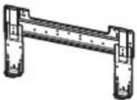 | 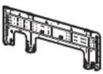 | 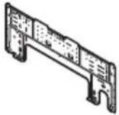 | 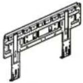 | 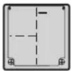 | |
| Type "B" screws | |||||
 | |||||
| Type "A" screw (6 EA) Type "A" screw (8 EA) Type "A" screw (7 EA) | Type "A" screw and plastic anchors | ||||
 |  |  |  | ||
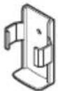
| Holder Remote Control | |||||
 | |||||
Installation Tools
| Figure FigureName | Name | ||
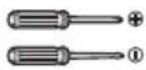 | Screw driver | 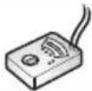 | Multi-meter |
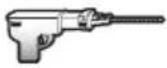 | Electric drill | [Z100] | Hexagonal wrench |
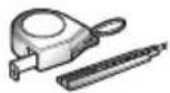 | Measuring tape, Knife | 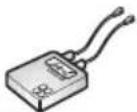 | Ammeter |
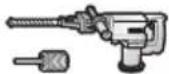 | Hole core drill | 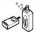 | Gas-leak detector |
| [TCH] | Spanner | 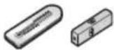 | Thermometer, Level |
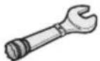 | Torque wrench | [H7W] | Flaring tool set |
INSTALLATION OF INDOOR, OUTDOOR UNIT
Read completely, then follow step by step.
Select the best location
Indoor unit
1 Do not have any heat or steam near the unit.
2 Select a place where there are no obstacles in front of the unit.
3 Make sure that condensation drainage can be conveniently routed away.
4 Do not install near a doorway.
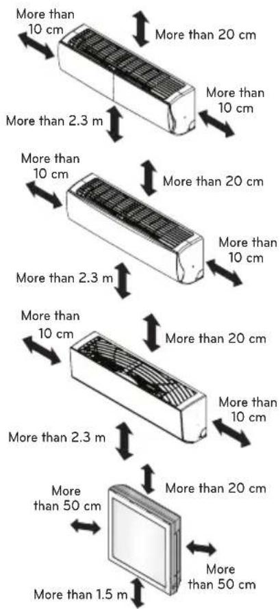
5 Ensure the spaces indicated by arrows from the wall, ceiling, fence or other obstacles.
6 Use a stud finder to locate studs to prevent unnecessary damage to the wall.

CAUTION
Install the indoor unit on the wall where the height from the floors more than 2.3 meters. (ART COOL Type Only 1.5 m)
text_image
More than 10 cm More than 20 cm More than 10 cm More than 2.3 m More than 10 cm More than 20 cm More than 10 cm More than 2.3 m More than 10 cm More than 20 cm More than 10 cm More than 2.3 m More than 50 cm More than 1.5 m More than 20 cm More than 50 cmOutdoor unit
1 If an awning is built over the unit to prevent direct sunlight or rain exposure, make sure that heat radiation from the condenser is not restricted.
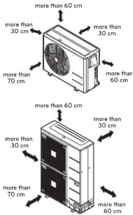
2 Ensure that the spaces indicated by arrows around front, back and side of the unit.
3 Do not place animals and plants in the path of the warm air.
4 Take the air conditioner weight into account and select a place where noise and vibration are minimum.
5 Select a place so that the warm air and noise from the air conditioner do not disturb neighbors.
Rooftop Installations
If the outdoor unit is installed on a roof structure, be sure to level the unit. Ensure the roof structure and anchoring method are adequate for the unit location. Consult local codes regarding rooftop mounting.
text_image
more than 60 cm more than 30 cm more than 70 cm more than 60 cm more than 30 cm more than 70 cm more than 60 cmFoundation for Installation
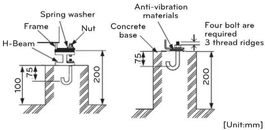
- Check the strength and level of the installation ground so that the unit will not cause any operating vibration or noise after installation.
- Fix the unit securely by means of the foundation bolts. (Prepare 4sets of M12 foundation bolts, nuts and washers each which are available on the market.)
- It is best to screw in the foundation bolts until their length are 20mm from the foundation surface.
text_image
Spring washer Frame Nut H-Beam Anti-vibration materials Concrete base Four bolt are required 3 thread ridges 75 200 100 75 200 [Unit:mm]Foundation bolt executing method
Piping length and elevation
Distributor type Models (Unit: m)
| Phase | Capacity (kBtu/h) | Total Length | Max Main Pipe Length (A/B) | Total Branch Pipe Length | Max Branch Pipe Length | Max Elevation (h1) | In - In Elevation (h2) |
| 1 ∅ | 40 100 | 50 50 15 30 | 15 | ||||
| 48 135 | 55 80 15 30 | 15 | |||||
| 56 145 | 55 90 15 30 | 15 |
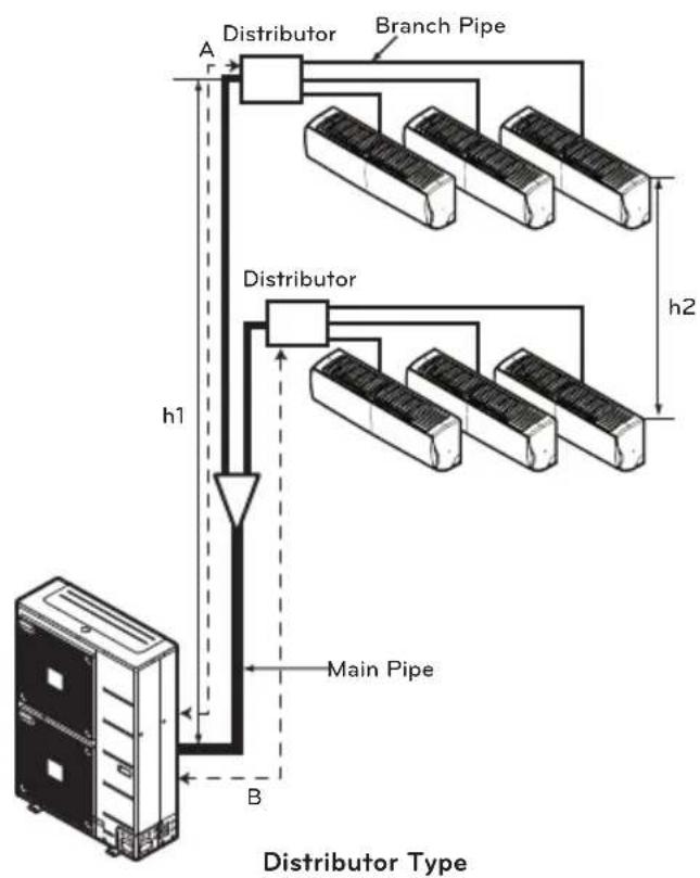
flowchart
graph TD
    A["Host"] --> B["Distributor Type"]
    B --> C["Main Pipe"]
    C --> D["Distributor"]
    D --> E["Branch Pipe"]
    E --> F["h1"]
    F --> G["Main Pipe"]
    G --> H["h2"]

CAUTION
Capacity is based on standard length and maximum allowance length is on the basis of reliability. If outdoor unit is at higher elevation than the indoor units, after 24 m of vertical height, 1 oil trap is required.
Refrigerant charge
The calculation of the additional charge should be taken in account for the length of extra pipe.
Distributor type Models (Unit: m)
| Phase Capacity(kBtu/h) | Main Piping length Branch | piping length | |||
| Standard length(m) | Additional refrigerant(g/m) | Standard length(m) | Additional refrigerant(g/m) | ||
| 1 ∅ | 40 5 50 5 | 20 | |||
| 48 5 50 5 | 20 | ||||
| 56 5 50 5 | 20 | ||||
| 3 ∅ | 42 5 50 5 | 20 | |||
| 48 5 50 5 | 20 | ||||
| 56 5 50 5 | 20 | ||||
• Distributor type Models
Additional charge (g) = (( Total Main piping Length - Main Standard Length ) x 50 g/m
+(A Room Branch Length - Standard Length) x 20 g/m
+(B Room Branch Length - Standard Length) × 20 g/m
+ (C Room Branch Length - Standard Length) × 20 g/m +..
- CF(Correction Factor) x 100
*CF = Max. number of connectable indoor unit - Total number of connected indoor unit
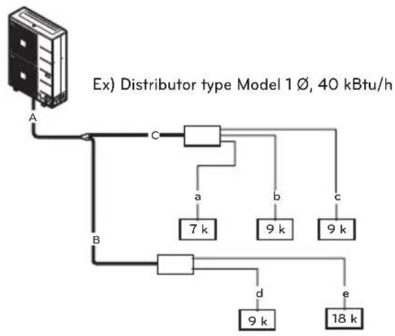
flowchart
graph TD
    A["Ex) Distributor type Model 1 ∅, 40 kBtu/h"] -->|A| B
    A -->|B| C
    C -->|a| D["7 k"]
    C -->|b| E["9 k"]
    C -->|c| F["9 k"]
    C -->|d| G["9 k"]
    C -->|e| H["18 k"]
• Total main pipe(A+B+C) = 30 m
• Each branch pipe
$$ \begin{array}{l} a = 1 0 m \ b = 8 m \ c = 5 m \ d = 3 m \ e = 1 0 m \ \end{array} $$
*Additional Charge
$$ \begin{array}{l} = ((3 0 - 5) \times 5 0 + (1 0 - 5) \times 2 0 + (8 - 5) \times 2 0 \ + (5 - 5) \times 2 0 + (3 - 5) \times 2 0 + (1 0 - 5) \times 2 0) \ - (7 - 5) \times 1 0 0 = 1 2 7 0 \mathrm{g} \ \end{array} $$
FLARING WORK AND CONNECTION OF PIPING
Flaring work
Main cause for gas leakage is due to defect in flaring work. Carry out correct flaring work in the following procedure.
Cut the pipes and the cable
- Use the piping kit accessory or the pipes purchased locally.
- Measure the distance between the indoor and the outdoor unit.
- Cut the pipes a little longer than measured distance.
- Cut the cable 1.5 m longer than the pipe length.
Burrs removal
- Completely remove all burrs from the cut cross section of pipe/tube.
- Put the end of the copper tube/pipe in a downward direction as you remove burrs in order to avoid dropping burrs into the tubing.
Putting nut on
- Remove flare nuts attached to indoor and outdoor unit, then put them on pipe/tube having completed burr removal. (not possible to put them on after flaring work)
Flaring work
- Carry out flaring work using flaring tool as shown below.
| Pipe diameterInch (mm) | A inch (mm) | |
| Wing nut type | Clutch type | |
| ∅ 1/4 (∅ 6.35) 0 | 04~0.05(1.1~1.3) | 0~0.02(0~0.5) |
| ∅ 3/8 (∅ 9.52) 0 | 06~0.07(1.5~1.7) | |
| ∅ 1/2 (∅ 12.7) 0 | 06~0.07(1.6~1.8) | |
| ∅ 5/8 (∅ 15.88) 0 | 06~0.07(1.6~1.8) | |
| ∅ 3/4 (∅ 19.05) 0 | 07~0.08(1.9~2.1) | |
Firmly hold copper pipe in a bar in the dimension shown in the table below.

text_image
Copper tube 90 Slanted Uneven Rough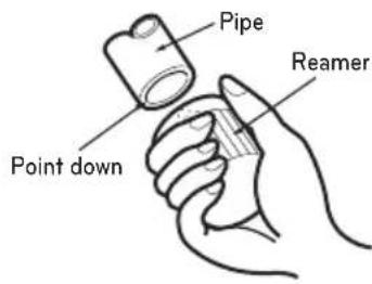
text_image
Pipe Point down Reamer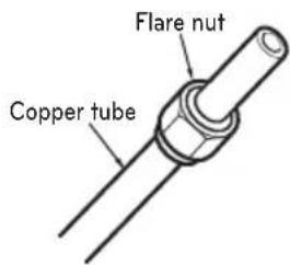
text_image
Flare nut Copper tube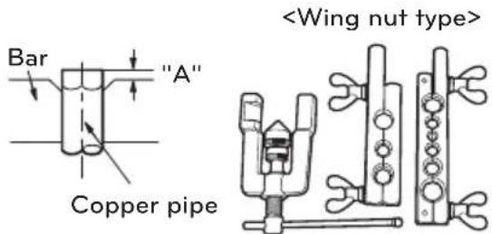
text_image
Bar "A" Copper pipe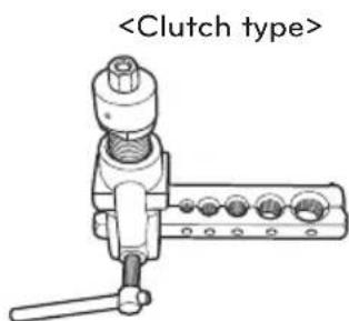
text_image
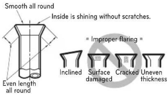
Check
- Compare the flared work with figure below.
- If flare is noted to be defective, cut off the flared section and do flaring work again.
text_image
Smooth all round Inside is shining without scratches. Even length all round = Improper flaring = Inclined Surface damaged Cracked Uneven thicknessConnection of piping - Indoor
Preparing the indoor unit's piping and drain hose for installation through the wall.
1 Route the indoor tubing and the drain hose in the direction of rear left or right
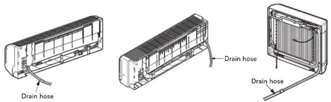
text_image
Drain hose Drain hose Drain hose2 Tape the tubing, drain hose and the connecting cable. Be sure that the drain hose is located at the lowest side of the bundle. Locating at the upper side can cause drain pan to overflow inside the unit.
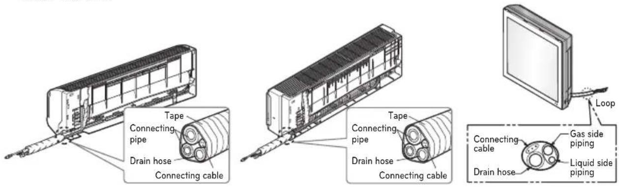
text_image
Tape Connecting pipe Drain hose Connecting cable Tape Connecting pipe Drain hose Connecting cable Loop Gas side piping Liquid side piping Connecting cable Drain hose
CAUTION
If the drain hose is routed inside the room, insulate the hose with an insulation material* so that dripping from "sweating"(condensation) will not damage furniture or floors.
*Foamed polyethylene or equivalent is recommended.
Indoor unit installation
Hook the indoor unit onto the upper portion of the installation plate.(Engage the two hooks of the rear top of the indoor unit with the upper edge of the installation plate.) Ensure that the hooks are properly seated on the installation plate by moving it left and right.
Press the lower left and right sides of the unit against the installation plate until the hooks engage into their slots(clicking sound).
Connecting the pipings to the indoor unit and drain hose to drain pipe
- Align the center of the pipings and sufficiently tighten the flare nut by hand.
- Tighten the flare nut with a wrench.
| Outside diameter | Torque |
| mm inch N | ·m |
| ∅6.35 1/4 16±2 | |
| ∅9.52 3/8 38±4 | |
| ∅12.7 1/2 55±6 | |
| ∅15.88 5/8 75±7 | |
| ∅19.05 3/4 110±10 |
- When extending the drain hose at the indoor unit, install the drain pipe.
Wrap the insulation material around the connecting portion.
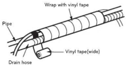
- Overlap the connection pipe insulation material and the indoor unit pipe insulation material. Bind them together with vinyl tape so that there is no gap.
- Wrap the area which accommodates the rear piping housing section with vinyl tape.
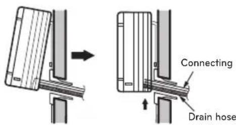
text_image
Connecting Drain hose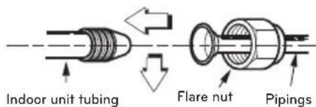
text_image
Indoor unit tubing Flare nut Pipings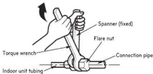
text_image
Spanner (fixed) Flare nut Torque wrench Connection pipe Indoor unit tubing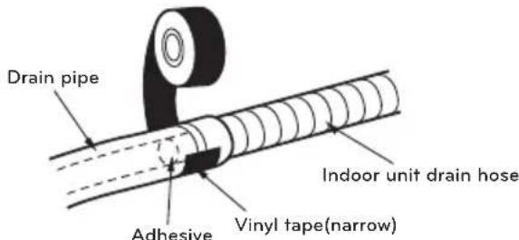
text_image
Drain pipe Adhesive Vinyl tape(narrow) Indoor unit drain hose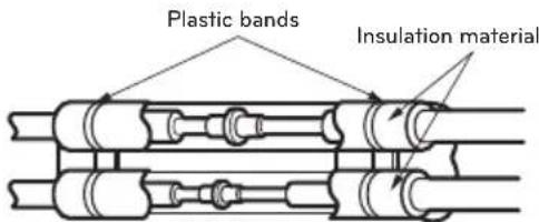
text_image
Plastic bands Insulation material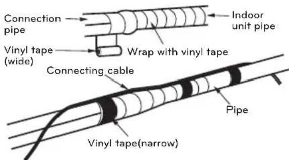
text_image
Connection pipe Vinyl tape (wide) Wrap with vinyl tape Connecting cable Vinyl tape(narrow) Indoor unit pipe Pipe- Bundle the piping and drain hose together by wrapping them with vinyl tape over the range within which they fit into the rear piping housing section.
text_image
Wrap with vinyl tape Pipe Vinyl tape(wide) Drain hose
CAUTION
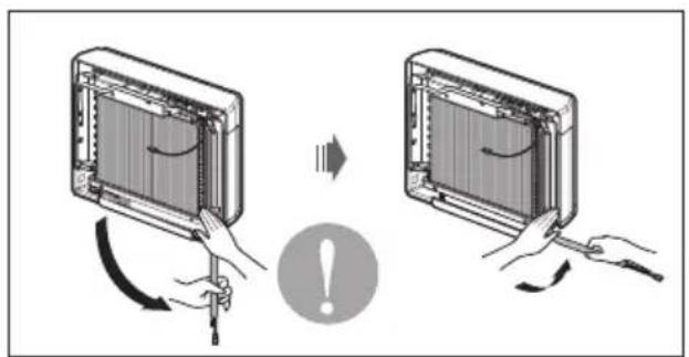
Installation Information (For right piping) For right piping, follow the instruction below.
Good case
Press on the upper side of clamp and unfold the tubing to downward slowly.
natural_image
Illustration of two devices with arrows indicating rotation and change, showing a warning symbol (no text or labels)Bad case
Following bending type from left to right could cause problem of pipe damage.

natural_image
Diagram showing two installation steps of an air conditioner panel with a prohibition symbol (no text or labels present)Connection of piping - Outdoor
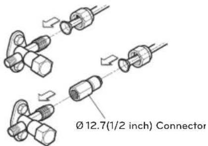
Align the center of the piping and sufficiently tighten the flare nut by hand.
Connecting pipe order
1) ROOM A\~E gas side pipe
2) ROOM A\~E liquid side pipe
Finally, tighten the flare nut with torque wrench until the wrench clicks.
- When tightening the flare nut with torque wrench ensure the direction for tightening follows the arrow on the wrench.
| Outside diameter | Torque |
| mm inch N | ·m |
| ∅6.35 1/4 16±2 | |
| ∅9.52 3/8 38±4 | |
| ∅12.7 1/2 55±6 | |
| ∅15.88 5/8 75±7 | |
| ∅19.05 3/4 110±10 |
text_image
Ø 12.7(1/2 inch) Connector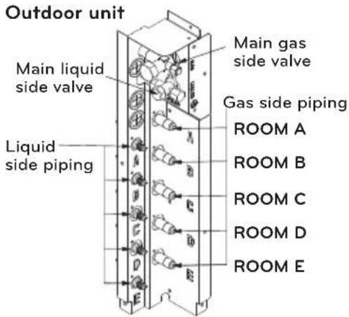
text_image
Outdoor unit Main liquid side valve Main gas side valve Gas side piping Liquid side piping ROOM A ROOM B ROOM C ROOM D ROOM E- For the units with capacity more than 48 kBtu/h, the installation piping is connectable in four directions.(refer to figure 1)
- When connecting in a downward direction, knock out the knockout hole of the base pan. (refer to figure 2)
Preventing foreign objects from entering (Figure3)
- Plug the pipe through-holes with putty or insulation material(procured locally) to stop up all gaps, as shown in the figure 3.
- Insects or small animals entering the outdoor unit may cause a short circuit in the electrical box.
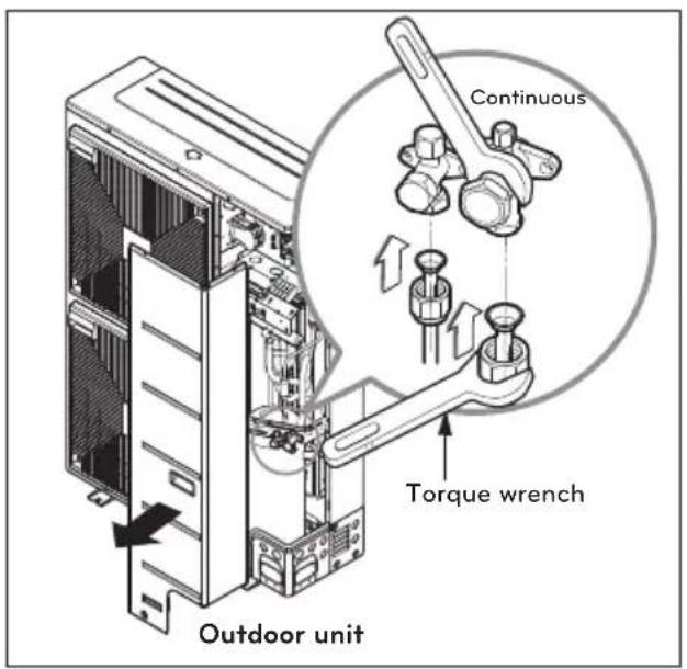
text_image
Continuous Torque wrench Outdoor unittext_image
Forward Backward Sideways Downwardtext_image
Liquid side piping (Smaller Dia.) Gas side piping (Bigger Dia.) Connecting wire Drain hose Connection pipetext_image
Knock-out Base panBranch
[unit:mm]| Model Gas Pipe Liquid Pipe | ||
| PMBL5620 | 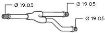 | 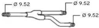 |
| PMBL1203F0 | 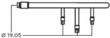 | 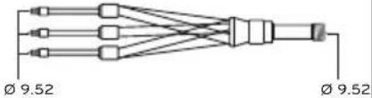 |
text_image
A Btext_image
Horizontal plane A Viewed from point A in direction of arrow Within +/- 10° Facing upwardstext_image
Insulator (included with kit) Liquid and gas pipe joints Tape (field supply) Insulator for field piping Insulation Tape (field supply) Insulation Tape(field supply) Insulation Tape(field supply)Installation
- This unit may be installed suspended from the ceiling or mounted on the wall. - This unit may only be installed horizontally, as shown in the diagram below.(Side B is facing up) However, it may be freely installed in any direction forward or back, and to the sides. - Be sure to leave a 600 mm square opening for service and inspection as shown in the diagram below, for both ceiling - suspended installation and wall-mounted installation. - This unit "does not require drain treatment" as it uses internal foam treatment as low-pressure piping insulation. - Service direction is the side B and C - The piping for the indoor unit may be led around in direction A - The inclination of side B must be within ±5 degrees forward or back or to the sides. [unit:mm] text_image
A ← (298) 250 245 Suspension bolt pitch. Ø 19.05 Ø 9.52 (337) B Main Pipe 3050 (111) 6030072 Cover ControlBranch Pipe ↑ C (36) 505050 (38)50 (56) 505050 Min 400 Min 400 (Servicing space) Min 30 Min 300 Inspection opening 600Installation of The Main Unit
(1) Ceiling-suspended type natural_image
Isometric line drawing of a rectangular electronic component with multiple ports and mounting feet (no text or symbols)natural_image
Pure electrical connector diagram without any text, numbers, or symbolsNOTE
- This unit has two different installation types: (1) Ceiling-suspended type and (2) wall-mounted type. - Choose the proper installation pattern according to the location of installation. - The installation location for printed wiring board can be changed. Follow the procedure specified in the "CONNECTING THE WIRING" section to change the location.Ceiling-suspended type
natural_image
Technical line drawings of two electrical contactor components with mounting holes and terminal blocks (no text or symbols)Procedure
1 Fix the furnished hanger metal with two screws.(4 locations in total). 2 Using an insert-hole-in- anchor, hang the hanging bolt. 3 Install a hexagon nut and a flat washer (locally-procured) to the hanging bolt as shown in the figure in the left, and lift the main unit to hang on the hanger metal. 4 After checking with a level that the unit is level, tighten the hexagon nut. \* The tilt of the unit should be within ±5° in front/back and left/right. text_image
BD unit Six-sided Nut (M10 or M8) Hanger metal Flat washer Hanging bolt (M10 or M8) 15.00Wall-mounted type
text_image
Screws(M5) (locally procude)Procedure
1 Fix the furnished hanger metal with two screws. (3 locations in total). 2 After checking with a level that the unit is level, fix the unit with the furnished wood screws. \* The tilt of the unit should be within ±5° in front/back and left/right. \* Block up the parts of hanger holes (2 places) by using insulation PE after installing the hanger.CAUTION
- Once a screw-hole on the main unit has had a screw hammered in, make sure to either hammer it again or cover it with aluminium tape. (This is to prevent condensation) - Be sure to install the unit with the ceiling-side up. - Do not install near bedrooms. the sound of refrigerant flowing through the piping may sometimes be audible.CONNECTING THE CABLE BETWEEN INDOOR UNIT AND OUTDOOR UNIT
Connect the cable to the Indoor unit
Connect the cable to the indoor unit by connecting the wires to the terminals on the control board individually according to the outdoor unit connection. (Ensure that the color of the wires of the outdoor unit and the terminal No. are the same as those of the indoor unit.) The earth wire should be longer than the common wires. The circuit diagram is not subject to change without notice. When installing, refer to the circuit diagram behind the panel front of Indoor Unit the wiring diagram on the Control Cover Inside Outdoor Unit. CAUTION
- The circuit diagram is not subject to change without notice. - Be sure to connect wires according to the wiring diagram. - Connect the wires firmly, so that not to be pulled out easily. - Connect the wires according to color codes by referring the wiring diagram. 7\~9 Unit (1 ∅) flowchart
graph TD
    A["POWER SUPPLY TERMINAL"] --> B["MAIN TERMINAL BLOCK"]
    B --> C["FUSE (250V / 36A)"]
    B --> D["NOISE FIL"]
    B --> E["TERMINAL BLOCK"]
    E --> F["DISCHARGE 2 (M_PIPE)"]
    E --> G["DISCHARGE (NV)"]
    E --> H["OUT AIR"]
    E --> I["EEV"]
    J["ROOM A"] --> K["1L"]
    L["ROOM B"] --> M["2N"]
    N["ROOM C"] --> O["3A"]
    P["ROOM D"] --> Q["4L"]
    R["ROOM E"] --> S["5B"]
    T["ROOM F"] --> U["6C"]
    V["ROOM G"] --> W["7N"]
    X["ROOM H"] --> Y["8N"]
    Z["ROOM I"] --> AA["9N"]
    AB["ROOM J"] --> AC["10N"]
    AD["ROOM K"] --> AE["11N"]
    AF["ROOM L"] --> AG["12N"]
    AH["ROOM M"] --> AI["13N"]
    AJ["ROOM N"] --> AK["14N"]
    AL["ROOM O"] --> AM["15N"]
    AN["ROOM P"] --> AO["16N"]
    AP["ROOM Q"] --> AQ["17N"]
    AR["ROOM R"] --> AS["18N"]
    AT["ROOM S"] --> AU["19N"]
    AV["ROOM T"] --> AW["20N"]
    AX["ROOM U"] --> AY["21N"]
    AZ["ROOM V"] --> BA["22N"]
    BB["ROOM W"] --> BC["23N"]
    BD["ROOM X"] --> BE["24N"]
    BF["ROOM Y"] --> BG["25N"]
    BH["ROOM Z"] --> BI["26N"]
    BJ["ROOM AA"] --> BK["27N"]
    BL["ROOM AB"] --> BM["28N"]
    BN["FUSE/BR/SW"] --> BO["FUSE/BR/SW"]
    BP["FUSE/BR/SW"] --> BQ["FUSE/BR/SW"]
    BR["FUSE/BR/SW"] --> BS["FUSE/BR/SW"]
    BT["FUSE/BR/SW"] --> BU["FUSE/BR/SW"]
    BV["FUSE/BR/SW"] --> BW["FUSE/BR/SW"]
    BX["FUSE/BR/SW"] --> BY["FUSE/BR/SW"]
    BZ["FUSE/BR/SW"] --> CA["FUSE/BR/SW"]
    CB["FUSE/BR/SW"] --> CC["FUSE/BR/SW"]
    DD["FUSE/BR/SW"] --> EE["FUSE/BR/SW"]
CAUTION
Provide a circuit breaker between power source and the unit as shown below. flowchart
graph TD
    A["Main power source"] --> B["Air Conditioner"]
    B --> C["Circuit Breaker\nUse a circuit breaker or time delay fuse."]
    C --> B
CAUTION
The power cord connected to the outdoor unit should be complied with the following specifications (Cable type approved by HAR or SAA).| Phase 1 ∅ | |||
| Capacity (kBtu/h) 40 48 56 | |||
| NORMAL CROSS SECTIONAL AREA 3.5 4.0 | 4.0 | ||
| Cable Type H07RN-F | |||
text_image
GN/YL 2text_image
Ø 7.5 mm GN/YL 20 mm NORMALConnect the cable to the Outdoor unit
1 Remove the cover control from the unit by loosening the screw. Connect the wires to the terminals on the control board individually as the following. 2 Secure the cable onto the control board with the holder (clamper). 3 Refix the cover control to the original position with the screw. 4 Use a recognized circuit breaker between the power source and the unit. A disconnection device to adequately disconnect all supply lines must be fitted. 1 ∅ Models| Capacity (kBtu/h) | 14 | 16 | 18 | 21 | 24 | 27 | 30 | 40 | 48 | 56 | ||
| Circuit Breaker (A) | 15 | 15 | 20 | 20 | 25 | 25 | 25 | 30 | 40 | 40 |
| Capacity (kBtu/h) | 42 | 48 | 56 | |
| Circuit Breaker (A) | 20 | 20 | 20 |
text_image
Outdoor unit Terminal block Over 15mm Holder for power supply cord Cover control Power cord Connecting cabletext_image
Loosen terminal screw Terminal blockCAUTION
After the confirmation of the above conditions, prepare the wiring as follows. 1 Never fail to have an individual power circuit specifically for the air conditioner. As for the method of wiring, be guided by the circuit diagram posted on the inside of control cover. 2 Firmly tighten the terminal screws to prevent them loosening. After tightening, pull the wires lightly to confirm that they do not move. (If they are loose the unit, the unit will not operate normally or it can cause burn-out of the wires.) 3 Specification of power source. 4 Confirm that electrical capacity is sufficient. 5 See to that the starting voltage is maintained at more than 90 percent of the rated voltage marked on the name plate. 6 Confirm that the cable thickness is as specified in the power source specification. (Particularly note the relation between cable length and thickness. 7 Do not install an earth leakage circuit breaker in a wet or moist area. 8 The following would be caused by voltage drop. \- Vibration of a magnetic switch, which will damage the contact point, fuse breaking, disturbance of the normal function of the overload. 9 The means for disconnection from a power supply shall be incorporated in the fixed wiring and have an air gap contact separation of at least 3 mm in each active(phase) conductors. 10 The Power cord connected to the unit should be selected according to the following specifications.Precautions when laying power wiring
Use round pressure terminals for connections to the power terminal block. text_image
Round pressure terminal Power wirenatural_image
Simple line drawing of a mechanical or architectural component with two circular holes and a circular base (no text or symbols)natural_image
Simple line drawing of a container with a stopper and a circular symbol below (no text or labels)natural_image
Simple line drawing of a roof structure with no text or symbols, featuring a circular symbol and a prohibition sign (no text or labels)Connection of Wiring
- Connect refrigerant pipes and connection wires to the appropriate ports made with matching alphabets (A, B and C) on this unit. - Follow the instructions on the wiring nameplate to connect the connection wires of indoor/outdoor units to terminal board numbers.(1, 2 and 3) Always fix each ground wire separately with a ground screw.(See the figure below.) - After completing the wiring, fix the outer coating of wires securely with wire clamps. The wire clamp on indoor unit side is furnished. Follow the procedure below to install. - Refer to the circuit diagram on the control cover inside outdoor unit. NOTE
The terminal board numbers are arranged from top to bottom in order of 1, 2 and 3.In Case of 3 rooms
text_image
ROOM A ROOM B ROOM C Connection wire for indoor units (H05VV, 4 wires, 0.75 mm) CN-PWR Connection wire for indoor units (H05RV, 4 wires, 1.2 mm)WARNING
Do not use tapped wires, stand wires, extensioncords, or starbust connections, as they may cause overheating, electrical shock, or fire. 1 Remove the control cover. Loosen the two screws, and slide the cover in the direction of the arrow. natural_image
Technical line drawing of a mechanical housing or enclosure with internal components and directional arrows (no text or symbols)text_image
Diagram showing a hand using a tool to switch an electrical panel with labeled components and connectionsnatural_image
Isometric technical drawing of a mechanical housing or enclosure with mounting flanges and internal components (no text or symbols)CHECKING THE DRAINAGE AND FORMING THE PIPINGS
Checking the Drainage
To check the drainage.
1 Pour a glass of water on the evaporator. 2 Ensure the water flows through the drain hose of the indoor unit without any leakage and goes out the drain exit. text_image
Connecting area drain hose Leakage checking Drain pan Drain hose Leakage checkingDrain piping
1 The drain hose should point downward for easy drain flow. text_image
Downward slopetext_image
Do not raise Water leakage Accumulated drain water Air Waving Water leakage Tip of drain hose dipped in water Water leakage Ditch Less than 50mm gapForming the Piping
Form the piping by wrapping the connecting portion of the indoor unit with insulation material and secure it with two kinds of vinyl tape. \- If you want to connect an additional drain hose, the end of the drain outlet should be routed above the ground. Secure the drain hose appropriately. In cases where the outdoor unit is installed below the indoor unit perform the following. 1 Tape the piping, drain hose and connecting cable from down to up. 2 Secure the tapped piping along the exterior wall using saddle or equivalent. text_image
Seal a small opening around the pipings with gum type sealer. Plastic band Taping Drain hose Pipings Connecting cable Power supply cordtext_image
Seal a small opening around the pipings with gum type sealant. Trap TrapAIR PURGING AND EVACUATION
The air and moisture remaining in the refrigerant system have undesirable effects as indicated below. - Pressure in the system rises. - Operating current rises. - Cooling(or heating) efficiency drops. - Moisture in the refrigerant circuit may freeze and block capillary tubing. - Water may lead to corrosion of parts in the refrigeration system. Therefore, after evacuating the system, take a leak test for the piping and tubing between the indoor and outdoor unit.Checking method
Preparation
Check that each tube(both liquid and gas side tubes) between the indoor and outdoor units have been properly connected and all wiring for the test run has been completed. Remove the service valve caps from both the gas and the liquid side on the outdoor unit. Check that both the liquid and the gas side service valves on the outdoor unit are kept closed at this stage.Leakage test
Connect the manifold valve(with pressure gauges) and dry nitrogen gas cylinder to this service port with charge hoses.CAUTION
Be sure to use a manifold valve for leakage test. If it is not available, use a stop valve for this purpose. The "Hi" knob of the manifold valve must always be kept close. \- Pressurize the system to no more than 150 P.S.I.G. with dry nitrogen gas and close the cylinder valve when the gauge reading reached 150 P.S.I.G. Next, test for leaks with liquid soap.CAUTION
To avoid nitrogen entering the refrigerant system in a liquid state, the top of the cylinder must be higher than its bottom when you pressurize the system. Usually, the cylinder is used in a vertical standing position. - Do a leakage test of all joints of the tubing(both indoor and outdoor) and both gas and liquid side service valves. Bubbles indicate a leak. Be sure to wipe off the soap with a clean cloth. - After the system is found to be free of leaks, relieve the nitrogen pressure by loosening the charge hose connector at the nitrogen cylinder. When the system pressure is reduced to normal, disconnect the hose from the cylinder. text_image
Indoor unit Outdoor unit Manifold valve Pressure gauge Charge hose Nitrogen gas cylinder(in vertical standing position)WARNING
Use a vacuum pump or Inert (nitrogen) gas when doing leakage test or air purge. Do not compress air or Oxygen and do not use Flammable gases. Otherwise, it may cause fire or explosion. \- There is the risk of death, injury, fire or explosion.Evacuation
\- Connect the charge hose end described in the preceding steps to the vacuum pump to evacuate the tubing and indoor unit. Confirm the "Lo" knob of the manifold valve is open. Then, run the vacuum pump. The operation time for evacuation varies with tubing length and capacity of the pump. The following table shows the time required for evacuation.| Required time for evacuation when 30 gal/h vacuum pump is used | |
| If tubing length is less than 10 m (33 ft) | If tubing length is longer than 10 m (33 ft) |
| Less than 0.5 Torr Less than 0.5 Torr | |
Finishing the Job
\- With a service valve wrench, turn the valve stem of liquid side valve counter-clockwise to fully open the valve. \- Turn the valve stem of gas side valve counterclockwise to fully open the valve. \- Loosen the charge hose connected to the gas side service port slightly to release the pressure, then remove the hose. \- Replace the flare nut and its bonnet on the gas side service port and fasten the flare nut securely with an adjustable wrench. This process is very important to prevent leakage from the system. \- Replace the valve caps at both gas and liquid side service valves and fasten them tight. This completes air purging with a vacuum pump. The air conditioner is now ready to test run. text_image
Indoor unit Outdoor unit Manifold valve Lo-Hi Pressure gauge Open Open Vacuum pumpINSTALLATION PI485
Fix the PI485 PCB as shown in Fig. Detailed installation method refer to PI485 Installation Manual. 1 ∅ : 40 kBtu/h, 48 kBtu/h, 56 kBtu/h natural_image
Technical line drawing of an internal server or rack unit showing internal components and a zoomed-in view (no text or symbols)TEST RUNNING
- Check that all tubing and wiring have been properly connected. - Check that the gas and liquid side service valves are fully open.Prepare remote control
Remove the battery cover by pulling it according to the arrow direction. Insert new batteries making sure that the (+) and (−) of battery are installed correctly. Reattach the cover by pushing it back into position. natural_image
Illustration of four hands performing a manual task with arrows indicating direction (no text or symbols present)NOTE
- Use 2 AAA(1.5 volt) batteries. Do not use rechargeable batteries. - Remove the batteries from the remote control if the system is not going to be used for a long time. text_image
Bolt Tubing connectionEvaluation of the performance
Operate unit for 15\~20 minutes, then check the system refrigerant charge: - Measure the pressure of the gas side service valve. - Measure the temperature of the intake and discharge of air. - Ensure the difference between the intake temperature and the discharge is more than 8 °C. \- For reference, the gas side pressure of optimum condition is as below.(Cooling)| Refrigerant | Outside ambient TEMP. | The pressure of the gas side service valve. |
| R410A 35 | °C (95 °F) | 8.5~9.5 kg/cm2G(120~135 P.S.I.G.) |
NOTE
If the actual pressure are higher than shown, the system is most likely over-charged, and charge should be removed. If the actual pressure are lower than shown, the system is most likely undercharged, and charge should be added. The air conditioner is now ready for use. text_image
Intake temperature Discharge air Discharge temperature Intake temperature Discharge air Discharge temperature Intake temperature Discharge air Discharge temperatureFUNCTION
DIP S/W Setting
If you set the DIP Switch when power is on, the change in setting is not applicable. The changing setting is enabled only when Power is reset. | Dip Switch | Function | |
| 1 | 2 3 4 | |
 | Normal Operation (No Function) | |
 | Forced Cooling Operation | |
 | Wiring Error Check | |
 | Saving Power Consumption (Step 1) | |
 | Saving Power Consumption (Step 2) | |
 | Mode Lock (Cooling) | |
 | Mode Lock (Heating) | |
 | Night Quiet Mode (Step 1) | |
 | Night Quiet Mode (Step 2) | |
 | Mode Lock (Cooling) + Night Quiet Mode (Step 1) | |
 | Mode Lock (Cooling) + Night Quiet Mode (Step 2) | |
 | Mode Lock (Cooling) + Saving Power Consumption (Step 1) | |
 | Mode Lock (Cooling) + Saving Power Consumption (Step 2) | |
 | Mode Lock (Heating) + Saving Power Consumption (Step 1) | |
 | Mode Lock (Heating) + Saving Power Consumption (Step 2) | |
WARNING
When you set the dip switch, you should turn off the circuit breaker or shut the power source of the product down. CAUTION
- Unless the applicable dip switch is set properly, the product may not work. - If you want to set a specific function, request that the installer sets the dip switch appropriately during installation. 40/48/56(1 ∅) kBtu/h text_image
DIP SW2 5 6 7 8 9 10 11 12 13 14 15 16 17 18 19 20 21 22 23 24 25 26 27 28 29 30 31 32 33 34 35 36 37 38 39 40 41 42 43 44 45 46 47 48 49 50 51 52 53 54 55 56 57 58 59 60 61 62 63 64 65 66 67 68 69 70 71 72 73 74 75 76 77 78 79 80Forced Cooling Operation
Adding the refrigerant in winter.Setting Procedure
1 Set the DIP Switch as follow after shutting the power source down.  2 Reset the power. 3 Check that the Red LED of PCB is on during work. (The indoor unit is operated by force.) 4 Add the specific amount of refrigerant. CAUTION
\- When the green LED of PCB is on, compressor is going to be off because of low pressure. \- You should return the DIP Switch to operate normally after finishing the operation.Wiring Error Check
You can check whether or not the wiring is correct.Setting Procedure
1 Set the DIP Switch as follow after shutting the power source down.  2 Reset the power. 3 Check that the Re and Green LED of PCB are on during work. (The indoor unit is operated by force.) 4 If the wiring is correct, the Green LED will light up. If the wiring is wrong, display as below (Display only wrong connection.) • Red LED : Piping Number - Green LED: Wiring Number (Room)Example)
If the Red LED blinks twice and the Green LED blinks 3 times, 2nd pipe is connected to 3rd room. text_image
LED1 (Red) 2 3 1 s 1 s LED1 (Green) 3 2 1 s1 sCAUTION
- If Indoor unit doesn't communicate to outdoor Unit, function could not be operated correctly. - Only the wrong wiring connection is displayed. You should change connection correctly to operate the product. - You should return the DIP Switch to operate normally after finishing wiring error check. - If Outdoor and Indoor temperature is too low in winter, the wiring error check function will not be operated. (Red LED is lighting)Saving Power Consumption
Saving Power Consumption operation is the function which enables efficient operation by lowering the maximum power consumption value. line
| Time | Power consumption and current | Nomal | |------|----------------------------------|-------| | 0 | 0 | 0 | | Peak | High | Low | | Final | Stable | Stable |Setting Procedure
1 Set the DIP Switch as follow after shutting the power source down.   Step 1 Step 2 2 Reset the power. Saving Power Consumption Current level.| Phase 1 ¢ | |||
| Model 40 k 48 k 56 k | |||
| Step1(A) | 22 | 24 | |
| Step2(A) | 18 | 20 | |
Night Quiet Mode
Night Quiet Mode operation lowers the noise level of the outdoor unit by changing the comp frequency and fan speed. This function is operated all night long.Setting Procedure
1 Set the DIP Switch as follow after shutting the power source down.   \*Noise level :Step 1 > Step 2 Step 1 Step 2 2 Reset the power. Night Quiet Mode with Mode Lock.  Mode Lock (Cooling) \+ Night Quiet Mode (step 1)  Mode Lock (Cooling) \+ Night Quiet Mode (step 2) CAUTION
- If comp frequency and fan speed are down, the cooling capacity may decrease accordingly. - This function is only available for Cooling Mode. - If you want to stop the Night Quiet Mode, Change the DIP Switch. - If operating indoor unit is set by the fan speed "Power", Night Quiet Mode will be stopped until fan speed "Power" is changed.Mode Lock
Setting Procedure
1 Set the DIP Switch as follow after shutting the power source down.  Only Cooling Mode Only Heating Mode  2 Reset the power. Mode Lock with Night Quiet Mode  Mode Lock (Cooling) \+ Night Quiet Mode (step 1)  Mode Lock (Cooling) \+ Night Quiet Mode (step 2) Saving Power Consumption with Mode Lock.  Mode Lock (Cooling) \+ Saving Power Consumption (step 1)  Mode Lock (Heating) \+ Saving Power Consumption (step 1)  Mode Lock (Cooling) \+ Saving Power Consumption (step 2)  Mode Lock (Heating) \+ Saving Power Consumption (step 2)MAX COMBINATION CAPACITY
Distributor Type| Phase | Capacity (kBtu/h) | Max Room No. | Combination Indoor Capacity (kBtu/h) | Combination Capacity Range (kBtu/h) |
| 1 ∅ | 40 7 5, 7, | 9, 12, 18, 24 16 | ~52 | |
| 48 8 5, 7, | 9, 12, 18, 24 19 | ~63 | ||
| 56 9 5, 7, | 9, 12, 18, 24 23 | ~73 |
CALCULATION METHOD FOR THE CONNECTABLE TOTAL CAPACITY OF INDOOR UNIT
Sum up the capacity of all indoor unit, but high static duct type indoor unit capacity weights 1.3 times Ex) 1 Outdoor unit : A9UW566FA3(FM56AH)(connectable maximum capacity is 73 kBtu) Indoor unit: AMNH186BHA0[MB18AH], AMNH246BHA0[MB24AH], AMNH246BHA0[MB24AH] (18 + 24 + 24) × 1.3 = 66 × 1.3 = 85.8 kBtu: this combination has a some problem 2 Out door unit: FM56AH Indoor unit: AMNH186BHA0[MB18AH], AMNH246BHA0[MB24AH], AMNH18GD5L0[MS18AH] (18 + 24) × 1.3 + 18 + 72.6: this combination can be okINSTALLATION GUIDE AT THE SEASIDE
CAUTION
• Air conditioners should not be installed in areas where corrosive gases, such as acid or alkaline gas, are produced. - Do not install the product where it could be exposed to sea wind (salty wind) directly. It can result corrosion on the product. Corrosion, particularly on the condenser and evaporator fins, could cause product malfunction or inefficient performance. - If outdoor unit is installed close to the seaside, it should avoid direct exposure to the sea wind. Otherwise it needs additional anticorrosion treatment on the heat exchanger.Selecting the location(Outdoor Unit)
If the outdoor unit is to be installed close to the seaside, direct exposure to the sea wind should be avoided. Install the outdoor unit on the opposite side of the sea wind direction. text_image
Sea wind ↓ Sea windtext_image
Windbreak Sea windSEASONAL WIND AND CAUTIONS IN WINTER
- Sufficient measures are required in a snow area or severe cold area in winter so that product can be operated well. - Get ready for seasonal wind or snow in winter even in other areas. - Install a suction and discharge duct not to let in snow or rain. - Install the outdoor unit not to come in contact with snow directly. If snow piles up and freezes on the air suction hole, the system may malfunction. If it is installed at snowy area, attach the hood to the system. - Install the outdoor unit at the higher installation console by 50 cm than the average snowfall (annual average snowfall) if it is installed at the area with much snowfall. - Where snow accumulated on the upper part of the Outdoor Unit by more than 10 cm, always remove snow for operation. natural_image
Technical line drawing of a mechanical fan assembly on a stand (no text or symbols)| Model Voltage, Hz | Current(A) | |
| A7UW40GFA0 | 220 V~ 60 Hz | 26.0 |
| A8UW48GFA0 | 27.0 | |
| A9UW56GFA0 |