
ThinkCentre M51 - Desktop computer LENOVO - Free user manual and instructions
Find the device manual for free ThinkCentre M51 LENOVO in PDF.


| Product Type | Desktop Computer |
| Brand | Lenovo |
| Model | ThinkCentre M51 |
| Dimensions | Height: 89 mm (3.5 in.), Width: 276 mm (10.9 in.), Depth: 273 mm (10.7 in.) |
| Weight | Minimum: 6.3 kg (13.4 lb), Maximum: 6.4 kg (14.1 lb) |
| Power Supply | 225 W with automatic voltage selection |
| Processor | Intel Pentium 4 with Hyper-Threading Technology, Intel Celeron |
| Memory | Up to 2.0 GB DDR2 SDRAM, two DIMM slots |
| Storage | Internal hard disk drive, optical drive (CD/DVD) on some models |
| Expansion Slots | One 32-bit PCI adapter connector |
| Ports | Front: 2 USB, headphone, microphone; Rear: 4 USB, Ethernet, VGA, parallel, serial, audio line in/out, keyboard, mouse |
| Audio | AC'97 with ADI 1981B codec, mono internal speaker (some models) |
| Network | 10/100/1000 Mbps Ethernet, Wake on LAN |
| Security | BIOS passwords, integrated cable lock (Kensington), security profile by device |
| Operating Temperature | 10°C to 35°C (50°F to 95°F) operating |
| Humidity | 8% to 80% operating |
| Acoustical Noise | Idle 28 dBA at bystander, Operating 30 dBA |
| Cleaning and Maintenance | Dust removal every 3 months; cleaning optical mouse lens or ball |
Frequently Asked Questions - ThinkCentre M51 LENOVO
User questions about ThinkCentre M51 LENOVO
0 question about this device. Answer the ones you know or ask your own.
Ask a new question about this device
Download the instructions for your Desktop computer in PDF format for free! Find your manual ThinkCentre M51 - LENOVO and take your electronic device back in hand. On this page are published all the documents necessary for the use of your device. ThinkCentre M51 by LENOVO.
USER MANUAL ThinkCentre M51 LENOVO
Before using this information and the product it supports, be sure to read the "Important safety information" on page v and Appendix E, "Notices," on page 41.
Fourth Edition (February 2006)
© Copyright Lenovo 2006.
Portions © Copyright International Business Machines Corporation 2005.
Allrightsreserved.
U.S. GOVERNMENT USERS – RESTRICTED RIGHTS: Our products and/or services are provided with RESTRICTED RIGHTS. Use, duplication or disclosure by the Government is subject to the GSA ADP Schedule contract with Lenovo Group Limited, if any, or the standard terms of this commercial license, or if the agency is unable to accept this Program under these terms, then we provide this Program under the provisions set forth in Commercial Computer Software–Restricted Rights at FAR 52.227-19, when applicable, or under Rights in Data-General, FAR 52.227.14 (Alternate III).
Contents
Important safety information. . . . . . v
Conditions that require immediate action. . . . . v
General safety guidelines . . . . . . . . . . vi
Service . . . . . . . . . . . . . . . vi
Power cords and power adapters . . . . . . vii
Extension cords and related devices . . . . . viii
Plugs and outlets . . . . . . . . . . . . viii
Batteries . . . . . . . . . . . . . . . . . viii
Heat and product ventilation . . . . . . . ix
CD and DVD drive safety. . . . . . . . . ix
Additional safety information. . . . . . . . . . x
Lithium battery notice . . . . . . . . . . . . x
Modem safety information . . . . . . . . . . xi
Laser compliance statement . . . . . . . . . . xi
Power supply statement . . . . . . . . . . . . xii
Overview . . . . . . . . . . . . . . . . xiii
Information resources. . . . . . . . . . . . . xiii
Chapter 1. Installing options ..... 1
Features. 1
Specifications 4
Supported operating positions . . . . . . . . . 5
Available options. 5
Handling static-sensitive devices. . . . . . . . . 6
Installing external options . . . . . . . . . . . . 7
Locating the connectors on the front of your computer . . . . . . . . . . . . . . . . . . 7
Locating the connectors on the rear of your computer 8
Obtaining device drivers ..... 9
Opening the cover . . . . . . . . . . . . . 10
Locating components . . . . . . . . . . . . 11
Identifying parts on the system board . . . . . 11
Installing memory . . . . . . . . . . . . . 12
Installing a PCI adapter . . . . . . . . . . . 14
Installing an optical drive . . . . . . . . . . 16
Security features. 16
Integrated cable lock . . . . . . . . . . . 17
Password protection . . . . . . . . . . . 17
Changing the battery . . . . . . . . . . . . 17
Erasing a lost or forgotten password (clearing
CMOS). 19
Closing the cover and connecting the cables . . . 20
Chapter 2. Using the Setup Utility
program 21
Starting the Setup Utility program. . . . . . . 21
Viewing and changing settings . . . . . . . . 21
Exiting from the Setup Utility program ..... 21
Using passwords 21
Password considerations . . . . . . . . . 22
User Password 22
Administrator Password . . . . . . . . . 22
IDE Drive User Password ..... 22
IDE Drive Master Password. . . . . . . . 23
Setting, changing, and deleting a password. . . 23
Resetting the hard disk drive and power-on password . . . . . . . . . . . . . . . . 23
Using Security Profile by Device . . . . . . . 24
Using IDE Drives Setup . . . . . . . . . . . 24
Selecting a startup device. 24
Selecting a temporary startup device . . . . . 25
Changing the startup sequence . . . . . . . 25
Appendix A. Updating system programs 27
System programs 27
Updating (flashing) BIOS from a diskette or CD-ROM . . . . . . . . . . . . . . . . . 27
Updating (flashing) BIOS from your operating system . . . . . . . . . . . . . . . . . . . 28
Recovering from a POST/BIOS update failure. . . 28
Appendix B. Cleaning the mouse . . . 29
Cleaning an optical mouse . . . . . . . . . . 29
Cleaning a mouse with a ball . . . . . . . . 29
Appendix C. Manual modem commands . . . . . . . . . . . . . . 31
Basic AT commands 31
Extended AT commands . . . . . . . . . . 33
MNP/V.42/V.42bis/V.44 commands . . . . . . 34
Fax Class 1 commands . . . . . . . . . . . 35
Fax Class 2 commands . . . . . . . . . . . 35
Voice commands. 36
Appendix D. Customer replaceable unit (CRU) parts list . . . . . . . . . . . 39
Appendix E. Notices ..... 41
Television output notice . . . . . . . . . . . 42
Trademarks 42
Index 43
Important safety information
Note
Please read important safety information first.
This information can help you safely use your desktop or notebook personal computer. Follow and retain all information included with your computer. The information in this document does not alter the terms of your purchase agreement ortheLenovo ^™ Statement of Limited Warranty.
Customer safety is important. Our products are developed to be safe and effective. However, personal computers are electronic devices. Power cords, power adapters, and other features can create potential safety risks that can result in physical injury or property damage, especially if misused. To reduce these risks, follow the instructions included with your product, observe all warnings on the product and in the operating instructions, and review the information included in this document carefully. By carefully following the information contained in this document and provided with your product, you can help protect yourself from hazards and create a safer computer work environment.
Note: This information includes references to power adapters and batteries. In addition to notebook computers, some products (such as speakers and monitors) ship with external power adapters. If you have such a product, this information applies to your product. In addition, your computer product contains a coin-sized internal battery that provides power to your system clock even when the machine is unplugged, so the battery safety information applies to all computers.
Conditions that require immediate action
Products can become damaged due to misuse or neglect. Some product damage is serious enough that the product should not be used again until it has been inspected and, if necessary, repaired by an authorized servicer.
As with any electronic device, pay close attention to the product when it is turned on. On very rare occasions, you might notice an odor or see a puff of smoke or sparks vent from your machine. Or you might hear sounds like popping, cracking or hissing. These conditions might merely mean that an internal electronic component has failed in a safe and controlled manner. Or, they might indicate a potential safety issue. However, do not take risks or attempt to diagnose the situation yourself contact the Customer Support Center.
Frequently inspect your computer and its components for damage or wear or signs of danger. If you have any question about the condition of a component, do not use the product. Contact the Customer Support Center or the product manufacturer for instructions on how to inspect the product and have it repaired, if necessary.
In the unlikely event that you notice any of the conditions listed below, or if you have any safety concerns with your product, stop using the product and unplug it from the power source and telecommunication lines until you can
speak to the Customer Support Center for further guidance. See "Information resources" on page xii for more information.
- Power cords, plugs, power adapters, extension cords, surge protectors, or power supplies that are cracked, broken or damaged.
• Signs of overheating, smoke, sparks or fire. - Damage to a battery (such as cracks, dents, creases), discharge from a battery, or a buildup of foreign substances on the battery.
- A cracking, hissing or popping sound, or strong odor that comes from the product.
- Signs that liquid has been spilled or an object has fallen onto the computer product, the power cord or power adapter.
- The computer product, the power cord or power adapter has been exposed to water.
• The product has been dropped or damaged in any way. - The product does not operate normally when you follow the operating instructions.
Note: If you notice these conditions with a product (such as an extension cord) that is not manufactured for or by Lenovo, stop using that product until you can contact the product manufacturer for further instructions, or until you get a suitable replacement.
Generalsafetyguidelines
Always observe the following precautions to reduce the risk of injury and property damage.
Service
Do not attempt to service a product yourself unless instructed to do so by the Customer Support Center or your documentation. Use only a service provider who is approved to repair your particular product.
Note: Some parts can be upgraded or replaced by the customer. These parts are referred to as Customer Replaceable Units, or CRUs. Lenovo expressly identifies CRUs as such, and provides documentation with instructions when it is appropriate for customers to replace those parts. You must closely follow all instructions when performing such replacements. Always make sure that the power is turned off and that the product is unplugged from any power source before you attempt the replacement. If you have any questions or concerns, contact the Customer Support Center.
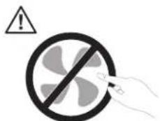
Although there are no moving parts in your computer after the power cord has been disconnected, the following warnings are required for proper UL certification.
Danger
text_image
Warning symbol with prohibition sign and warning triangle, indicating no hazard or cautionHazardous moving parts. Keep fingers and other body parts away.
Attention

Before replacing any CRUs, turn off the computer and wait three to five minutes to let the computer cool before opening the cover.
Power cords and power adapters
Use only the power cords and power adapters supplied by the product manufacturer.
The power cords shall be safety approved. For Germany, it shall be H05VV-F, 3G, 0.75mm^2 , or better. For other countries, the suitable types shall be used accordingly.
Never wrap a power cord around the power adapter or other object. Doing so can stress the cord in ways that can cause the cord to fray, crack or crimp. This can present a safety hazard.
Always route power cords so that they will not be walked on, tripped over, or pinchedbyobjects.
Protect the cord and power adapters from liquids. For instance, do not leave your cord or power adapter near sinks, tubs, toilets, or on floors that are cleaned with liquid cleansers. Liquids can cause a short circuit, particularly if the cord or power adapter has been stressed by misuse. Liquids can also cause gradual corrosion of the power cord terminals and/or the connector terminals on the adapter which can eventually result in overheating.
Always connect power cords and signal cables in the correct order and ensure that all power cord connectors are securely and completely plugged into receptacles.
Do not use any power adapter that shows corrosion at the ac input pins and/or shows signs of overheating (such as deformed plastic) at the ac input or anywhere on the power adapter.
Do not use any power cords where the electrical contacts on either end show signs of corrosion or overheating or where the power cord appears to have been damaged in any way.
Extension cords and related devices
Ensure that extension cords, surge protectors, uninterruptible power supplies, and power strips that you use are rated to handle the electrical requirements of the product. Never overload these devices. If power strips are used, the load should not exceed the power strip input rating. Consult an electrician for more information if you have questions about power loads, power requirements, and inputratings.
Plugsandoutlets
If a receptacle (power outlet) that you intend to use with your computer equipment appears to be damaged or corroded, do not use the outlet until it is replaced by a qualified electrician.
Do not bend or modify the plug. If the plug is damaged, contact the manufacturer to obtain a replacement.
Some products are equipped with a three-pronged plug. This plug fits only into a grounded electrical outlet. This is a safety feature. Do not defeat this safety feature by trying to insert it into a non-grounded outlet. If you cannot insert the plug into the outlet, contact an electrician for an approved outlet adapter or to replace the outlet with one that enables this safety feature. Never overload an electrical outlet. The overall system load should not exceed 80 percent of the branch circuit rating. Consult an electrician for more information if you have questions about power loads and branch circuit ratings.
Be sure that the power outlet you are using is properly wired, easily accessible, and located close to the equipment. Do not fully extend power cords in a way that will stress the cords.
Carefully connect and disconnect the equipment from the electrical outlet.
Batteries
All personal computers manufactured by Lenovo contain a non-rechargeable coin cell battery to provide power to the system clock. In addition, many mobile products, such as notebook computers, utilize a rechargeable battery pack to provide system power when in portable mode. Batteries supplied by Lenovo for use with your product have been tested for compatibility and should only be replaced with approved parts.
Never attempt to open or service any battery. Do not crush, puncture, or incinerate batteries or short circuit the metal contacts. Do not expose the battery to water or other liquids. Only recharge the battery pack strictly according to instructions included in the product documentation.
Battery abuse or mishandling can cause the battery to overheat, which can cause gasses or flame to "vent" from the battery pack or coin cell. If your battery is damaged, or if you notice any discharge from your battery or the buildup of foreign materials on the battery leads, stop using the battery and obtain a replacement from the battery manufacturer.
Batteries can degrade when they are left unused for long periods of time. For some rechargeable batteries (particularly Lithium Ion batteries), leaving a battery unused in a discharged state could increase the risk of a battery short circuit, which could shorten the life of the battery and can also pose a safety hazard. Do not let rechargeable Lithium-Ion batteries completely discharge or store these batteries in a discharged state.
Heat and product ventilation
Computers generate heat when turned on and when batteries are charging. Notebook PCs can generate a significant amount of heat due to their compact size. Always follow these basic precautions:
- Do not leave the base of your notebook computer in contact with your lap or any part of your body for an extended period when the computer is functioning or when the battery is charging. Your computer produces some heat during normal operation. Extended contact with the body could cause discomfort or, potentially, a skin burn.
- Do not operate your computer or charge the battery near flammable materials or inexplosive environments.
- Ventilation slots, fans and/or heat sinks are provided with the product for safety, comfort, and reliable operation. These features might inadvertently become blocked by placing the product on a bed, sofa, carpet, or other flexible surface. Never block, cover or disable these features.
You should inspect your desktop computer for dust accumulation at least once every three months. Before inspecting your computer, turn off the power and unplug the computer's power cord from the electrical outlet; then remove any dust from vents and perforations in the bezel. If you notice external dust accumulation, you should also examine and remove dust from the inside of the computer including heat sink inlet fins, power supply vents, and fans. Always turn off and unplug the computer before opening the cover. If possible, avoid operating your computer within 2 feet of high-traffic areas. If you must operate your computer in or near a high-traffic area, you should inspect and, if necessary, clean your computermorefrequently.
For your safety and to maintain optimum computer performance, always follow these basic precautions with your desktop computer:
- Keep the cover closed whenever the computer is plugged in.
- Regularly inspect the outside of the computer for dust accumulation.
- Remove dust from vents and any perforations in the bezel. More frequent cleanings might be required for computers in dusty or high-traffic areas.
- Do not restrict or block any ventilation openings.
- Do not store or operate your computer inside furniture, as this might increase the risk of overheating.
• Airflow temperatures into the computer should not exceed 35^ C ( 95^ F). - Do not use non-desktop air filtration devices.
CD and DVD drive safety
CD and DVD drives spin discs at a high speed. If a CD or DVD is cracked or otherwise physically damaged, it is possible for the disc to break apart or even shatter when the CD drive is in use. To protect against possible injury due to this situation, and to reduce the risk of damage to your machine, do the following:
• Always store CD/DVD discs in their original packaging
• Always store CD/DVD discs out of direct sunlight and away from direct heat sources
- Remove CD/DVD discs from the computer when not in use
- Do not bend or flex CD/DVD discs, or force them into the computer or their packaging
- Check CD/DVD discs for cracks before each use. Do not use cracked or damaged discs
Additionalsafetyinformation
Danger Electrical current from power, telephone, and communication cables is hazardous.
To avoid a shock hazard:
- Do not connect or disconnect any cables or perform installation, maintenance, or reconfiguration of this product during an electrical storm.
- Connect all power cords to a properly wired and grounded electrical outlet.
- Connect to properly wired outlets any equipment that will be attached to this product.
- When possible, use one hand only to connect or disconnect signal cables.
- Never turn on any equipment when there is evidence of fire, water, or structural damage.
- Disconnect the attached power cords, telecommunications systems, networks, and modems before you open the device covers, unless instructed otherwise in the installation and configuration procedures.
- Connect and disconnect cables as described in the following table when installing, moving, or opening covers on this product or attached devices.
| Toconnect:1. Turn everything OFF.2. First, attach all cables to devices.3. Attach signal cables to connectors.4. Attach power cords to outlet.5. Turn device ON. | Todisconnect:1. Turn everything OFF.2. First, remove power cords from outlet.3. Remove signal cables from connectors.4. Remove all cables from devices. |
Lithiumbatterynotice
Caution Danger of explosion if battery is incorrectly replaced.
When replacing the lithium coin cell battery, use only the same or an equivalent type that is recommended by the manufacturer. The battery contains lithium and can explode if not properly used, handled, or disposed of.
Donot:
- Throw or immerse into water
• Heat to more than 100°C (212°F)
• Repair or disassemble
Dispose of the battery as required by local ordinances or regulations.
Modemsafetyinformation
Caution
To reduce the risk of fire, use only No. 26 AWG or larger telecommunicationlinecord.
To reduce the risk of fire, electrical shock, or injury when using telephone equipment, always follow basic safety precautions, such as:
- Never install telephone wiring during a lightning storm.
- Never install telephone jacks in wet locations unless the jack is specifically designed for wet locations.
- Never touch uninsulated telephone wires or terminals unless the telephone line has been disconnected at the network interface.
- Use caution when installing or modifying telephone lines.
- Avoid using a telephone (other than a cordless type) during an electrical storm. There may be a remote risk of electric shock from lightning.
- Do not use the telephone to report a gas leak in the vicinity of the leak.
Lasercompliancestatement
Some personal computer models are equipped from the factory with a CD-ROM drive or a DVD-ROM drive. CD-ROM drives and DVD-ROM drives are also sold separately as options. CD-ROM drives and DVD-ROM drives are laser products. These drives are certified in the U.S. to conform to the requirements of the Department of Health and Human Services 21 Code of Federal Regulations (DHHS 21 CFR) Subchapter J for Class 1 laser products. Elsewhere, these drives are certified to conform to the requirements of the International Electrotechnical Commission (IEC) 825 and CENELEC EN 60 825 for Class 1 laser products.
When a CD-ROM drive or a DVD-ROM drive is installed, note the following handling instructions.
Caution
Use of controls or adjustments or performance of procedures other than those specified herein might result in hazardous radiation exposure.
Removing the covers of the CD-ROM drive or DVD-ROM drive could result in exposure to hazardous laser radiation. There are no serviceable parts inside the CD-ROM drive or DVD-ROM drive. Do not remove the drive covers.
Some CD-ROM drives and DVD-ROM drives contain an embedded Class 3A or Class 3B laser diode. Note the following statement.
Danger
Laser radiation when open. Do not stare into the beam, do not view directly with optical instruments, and avoid direct exposure to the beam.
Powersupplystatement
Never remove the cover on a power supply or any part that has the following labelattached.

text_image
Two yellow traffic signs: a crossed-out no-smoking symbol and a black triangular warning sign with a lightning bolt.Hazardous voltage, current, and energy levels are present inside any component that has this label attached. There are no serviceable parts inside these components. If you suspect a problem with one of these parts, contact a service technician.
Overview
Thank you for selecting a ThinkCentre ^® computer. Your computer incorporates many of the latest advances in computer technology and can be upgraded as your needschange.
This publication supports several computer models. Information in this section will help you identify your computer and help you find the chapter that contains information specific to your computer.
Adding hardware options to your computer is an easy way to increase its capabilities. Instructions for installing external and internal options are included in this publication. When adding an option, use these instructions along with the instructions that come along with the option.
Information resources
The Quick Reference that comes with your computer provides information for installing your computer and starting the operating system. It also includes basic troubleshooting information, software recovery procedures, help and service information, and warranty information.
TheThinkVantage™ Productivity Center program, on your desktop, provides a link to more information about your computer.
If you have Internet access, the most up-to-date information for your computer is available from the World Wide Web.
You can find the following information:
• CRU removal and installation instructions
•Publications
- Troubleshooting information
- Parts information
- Downloads and drivers
- Links to other useful sources of information
• Support phone list
To access this information, point your browser to: http://www.lenovo.com/support/
Chapter 1. Installing options
natural_image
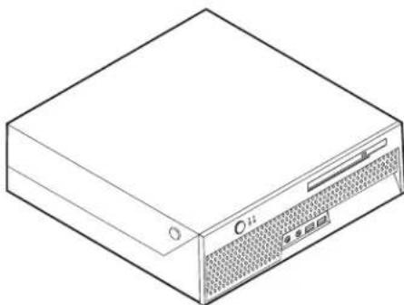
Line drawing of a computer drive chassis with ventilation slots and ports (no text or symbols)This chapter provides an introduction to the features and options that are available for your computer. You can expand the capabilities of your computer by adding memory or adapters. When installing an option, use these instructions along with the instructions that come with the option.
Note: Use only parts provided by Lenovo.
Important
Before you install or remove any option, read "Important safety information" on page v. These precautions and guidelines will help you work safely.
Features
This section provides an overview of the computer features and preinstalled software.
Systeminformation
The following information covers a variety of models. For information for your specific model, use the Setup Utility. See Chapter 2, "Using the Setup Utility program," on page 21
Microprocessor (varies by model type)
- Intel ^ Pentium ^ 4 processor with HyperThreading Technology
• Intel Pentium 4 processor
•IntelCeleron ^® processor
- Internal cache (size varies by model type)
Memory
Support for two double data rate 2 (DDR2) dual inline memory modules (DIMMs)
Internaldrives
• Internal hard disk drive
• Optical drive (some models)
Videosubsystem
An integrated graphics controller for a Video Graphics Array (VGA) monitor
Audiosubsystem
• AC'97 with ADI 1981B Audio Codec
• Line in and line out connectors on the rear panel
- Microphone and headphone connectors on the front panel
• Mono internal speaker (some models)
Connectivity
- 10/100/1000 Mbps integrated Intel Ethernet controller that supports the Wake onLAN® feature(somemodels)
- Soft modem V.90/V.44 (some models)
Systemmanagementfeatures
- Remote Program Load (RPL) and Dynamic Host Configuration Protocol (DHCP)
- Wake on LAN
- Wake on Ring (in the Setup Utility program, this feature is called Serial Port Ring Detect for an external modem)
- Remote Administration
• Automatic power-on startup
• System Management (SM) BIOS and SM software - Ability to store Power on self-test (POST) hardware test results
Input/outputfeatures
• 25-pin, Extended Capabilities Port (ECP)/Extended Parallel Port (EPP)
• 9-pin serial connector
- Six 4-pin, USB connectors (two on front panel and four on rear panel)
• Standard mouse connector
• Standard keyboard connector
- Ethernet connector
• VGA monitor connector
- Four audio connectors (headphone and microphone on front panel and line in and line out on rear panel)
Expansion
- Two drive bays
• One 32-bit peripheral component interconnect (PCI) adapter connector
Power
• 225 W power supply with automatic voltage selection switch
• Automatic 50/60 Hz input frequency switching
• Advanced Power Management support
- Advanced Configuration and Power Interface (ACPI) support
Securityfeatures
- Keyboard with fingerprint reader (some models, see the ThinkVantage Productivity Center program for more information)
- User and administrator passwords for BIOS access
- Support for the addition of an integrated cable lock (Kensington lock) to secure thecover
- Startup sequence control
- Startup without diskette drive, keyboard, or mouse
• Unattended start mode - Hard disk I/O control
- Serial and parallel port I/O control
• Security profile by device
Your computer might come with preinstalled software. If it does, an operating system, device drivers to support built-in features, and other support programs are included.
Operating systems, preinstalled (varies by model type)
Note: Not all countries or regions will have these operating systems.
•Microsoft ^® Windows ^® XPHomeEdition
• Microsoft Windows XP Professional
Operating systems certified or tested for compatibility ^1
• Microsoft Windows 2000
•Linux ^®
Specifications
This section lists the physical specifications for your computer.
Dimensions
Height: 89 mm (3.5 in.)
Width: 276 mm (10.9 in.)
Depth: 273 mm (10.7 in)
Weight
Minimum configuration as shipped: 6.3 kg (13.4 lb)
Maximum configuration: 6.4 kg (14.1 lb)
Environment
Airtemperature:
Operating at 0 - 3000 ft (914.4 m): 10° to 35°C
(50°to95°F)
Operating at 3000 ft - 6562 ft (2000 m): 10° to
32^ (50^ to 89.6^)
Non-operating: 10^ to 43^ C ( 50^ to 110^ F)
Humidity:
Operating: 8% to 80%
Non-operating: 8% to 80%
Transit:8%to90%
Maximum altitude: 2000 m (6562 ft)
Electricalinput
Inputvoltage:
Lowrange:
Minimum: 100 V ac
Maximum: 127 V ac
Input frequency range: 50/60 Hz
Highrange:
Minimum: 200 V ac
Maximum: 240 V ac
Input frequency range: 50/60 Hz
Input kilovolt-amperes (kVA) (approximate):
Minimum configuration as shipped: 0.09 kVA
Maximum configuration: 0.23 kVA
Heat output (approximate) in British thermal units (Btu) perhour:
Minimum configuration: 256 Btu/hr (75 watts)
Maximum configuration: 682 Btu/hr (200 watts)
Airflow
Approximately 20 cubic feet (0.57 cubic meters) per minute
Acousticalnoise-emissionvalues
Averagesound-pressurelevels:
Atoperatorposition:
Idle:26dBA
Operating:34dBA
At bystander position - 1 meter (3.3 ft):
Idle:28dBA
Operating:30dBA
Declared (upper limit) sound-power levels:
Idle:3.8bels
Operating:4.3bels
Note: These levels were measured in controlled acoustical environments according to the procedures specified by the American National Standards Institute (ANSI) S12.10 and ISO 7779 and are reported in accordance with ISO 9296. Actual sound-pressure levels in a given location might exceed the average values stated because of room reflections and other nearby noise sources. The declared sound-power levels indicate an upper limit, below which a large number of computers will operate.
Supportedoperatingpositions
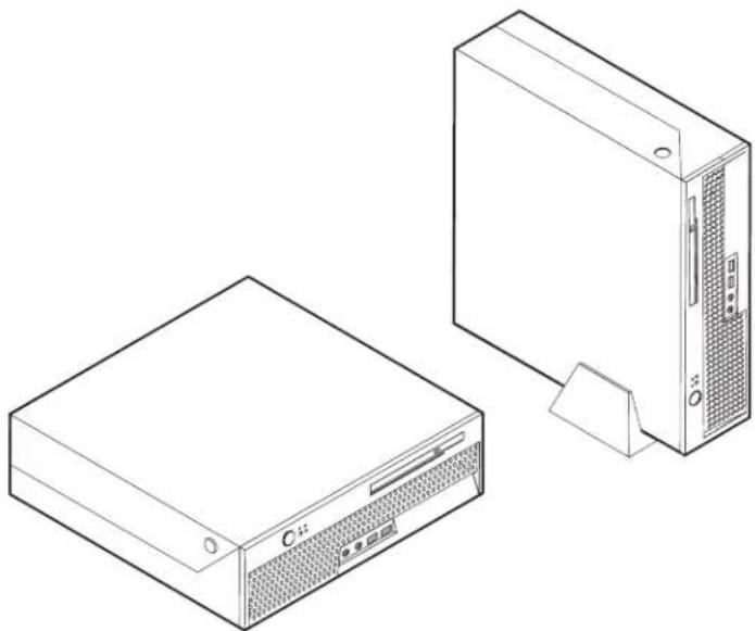
To provide proper air flow to internal components, you must position your computer in one of the positions as illustrated below. The vertical stand is optional.
natural_image
Line drawing of two electronic devices: a front-mounted tower and a desktop computer tower (no text or symbols)Availableoptions
The following are some available options:
- External options
- Parallel port devices, such as printers and external drives
- Serial port devices, such as external modems and digital cameras
- Audio devices, such as external speakers for the sound system
- USB devices, such as printers, joysticks, and scanners
- Security device, such as an integrated cable lock
-Monitors
•Internaloptions
- System memory, called dual inline memory modules (DIMMs)
- Peripheral component interconnect (PCI) adapters
- Optical drives, such as CD drives and DVD drives (some models)
For the latest information about available options, see the following World Wide Webpages:
•http://www.lenovo.com/us/en
•http://www.lenovo.com/support
You also can obtain information by calling the following telephone numbers:
- Within the United States, call 1-800-426-2968, your reseller, or marketing representative.
• Within Canada, call 1-800-565-3344 or 1-800-426-2968.
- Outside the United States and Canada, contact your Lenovo reseller or Lenovo marketing representative.
Handling static-sensitive devices
Static electricity, although harmless to you, can seriously damage computer componentsandoptions.
When you add an option, do not open the static-protective package containing the option until you are instructed to do so.
When you handle options and other computer components, take these precautions to avoid static electricity damage:
- Limit your movement. Movement can cause static electricity to build up around you.
- Always handle components carefully. Handle adapters and memory modules by the edges. Never touch any exposed circuitry.
- Prevent others from touching components.
- When you install a new option, touch the static-protective package containing the option to a metal expansion-slot cover or other unpainted metal surface on the computer for at least two seconds. This reduces static electricity in the package and your body.
- When possible, remove the option and install it directly in the computer without setting the option down. When this is not possible, place the static-protective package that the option came in on a smooth, level surface and place the option onit.
- Do not place the option on the computer cover or other metal surface.
Installingexternaloptions
This section shows the various external connectors on your computer to which you can attach external options, such as external speakers, a printer, or a scanner. For some external options, you must install additional software in addition to making the physical connection. When adding an external option, use the information in this section to identify the required connector, and then use the instructions that come with the option to help you make the connection and install any software or device drivers that are required for the option.
Locating the connectors on the front of your computer
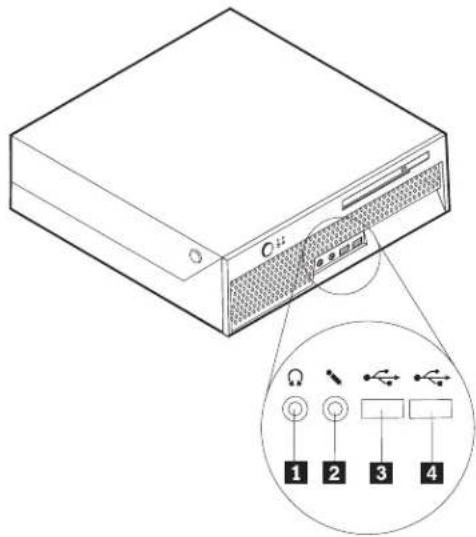
The following illustration shows the locations of the connectors on the front of the computer.
text_image
C12 Ω 1 2 3 41 Headphone connector
2 Microphone connector
3 USB connector
4 USB connector
Locating the connectors on the rear of your computer
The following illustration shows the locations of the connectors on the rear of the computer.
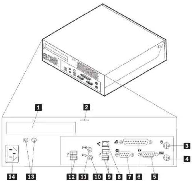
text_image
Diagram of a computer tower with labeled ports and connectors, showing internal components and wiring connections.1 PCI adapter connector
2 Integrated cable lock
3 Mouse connector
4 Keyboard connector
5 VGA monitor connector
6 Parallel connector
7 Serial connector
8 Ethernet connector
9 USB connectors
10 Audio line out connector
11 Audio line in connector
12 USB connectors
13 Diagnostic LEDs
14 Power connector
Note: Some connectors on the rear of the computer are color-coded to help you determine where to connect the cables on your computer.
ConnectorDescription
| Mouse connector | Used to attach a mouse, trackball, or other pointing device that uses a standard mouse connector. |
| Keyboard connector | Used to attach a keyboard that uses a standard keyboard connector. |
| Parallel connector | Used to attach a parallel printer, parallel scanner, or other devices that use a 25-pin parallel connector. |
| Serial connector | Used to attach an external modem, serial printer, or other devices that use a 9-pin serial connector. |
| Ethernet connector | Used to attach an Ethernet cable for a local area network (LAN).Note:To operate the computer within FCC Class B limits, use a Category 5 Ethernet cable. |
| USB connectors | Used to attach a device that requires a Universal Serial Bus (USB) connection, such as a USB scanner or USB printer. If you have more than six USB devices, you can purchase a USB hub, which you can use to connect additional USB devices. |
| Audio line out connector | Used to send audio signals from the computer to external devices, such as powered stereo speakers (speakers with built-in amplifiers), headphones, multimedia keyboards, or the audio line in connector on a stereo system or other external recording device. |
| Audio line in connector | Used to receive audio signals from an external audio device, such as a stereo system. When you attach an external audio device, a cable is connected between the audio line out connector of the device and the audio line in connector of the computer. |
Obtainingdevicedrivers
You can obtain device drivers for operating systems that are not preinstalled at http://www.lenovo.com/support on the World Wide Web. Installation instructions are provided in README files with the device-driver files.
Openingthecover
Important:
Read "Important safety information" on page v and "Handling static-sensitive devices" on page 6 before opening the computer cover.
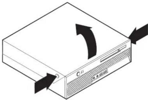
To open the computer cover:
-
Remove any media (DVDs, CDs, or tapes) from the drives, shut down your operating system, and turn off all attached devices and the computer.
-
Unplug all power cords from electrical outlets.
-
Disconnect all cables attached to the computer. This includes power cords, input/output (I/O) cables, and any other cables that are connected to the computer.
-
Remove the optional floor stand, if attached.
-
Remove any locking devices such as a cable lock that secure the cover.
-
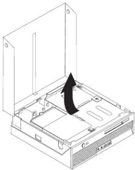
Press the buttons on the sides of the computer and pivot the cover upward to open the computer as shown.
natural_image
Diagram of a computer drive with arrows indicating rotation and sound waves (no text or symbols)Locatingcomponents
The following illustration will help you locate the various components in your computer.
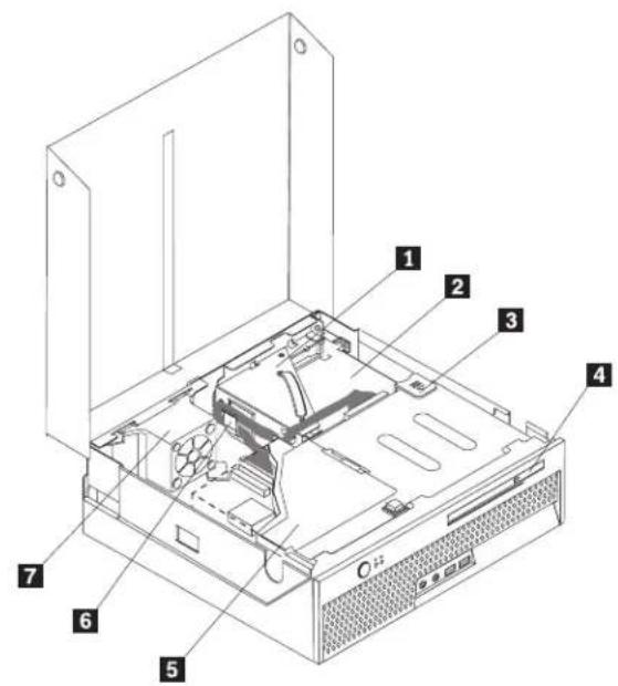
text_image
Technical diagram of a computer tower case with numbered components for identification1 PCI riser
5 Hard disk drive
2 Power supply assembly
6 Cable clip
3 Optical drive eject button
7 Rear fan bracket assembly
4 Opticaldrive
Identifying parts on the system board
The system board (sometimes called the planar or motherboard) is the main circuit board in your computer. It provides basic computer functions and supports a variety of devices that are factory-installed or that you can install later.
The following illustration shows the locations of parts on the system board.
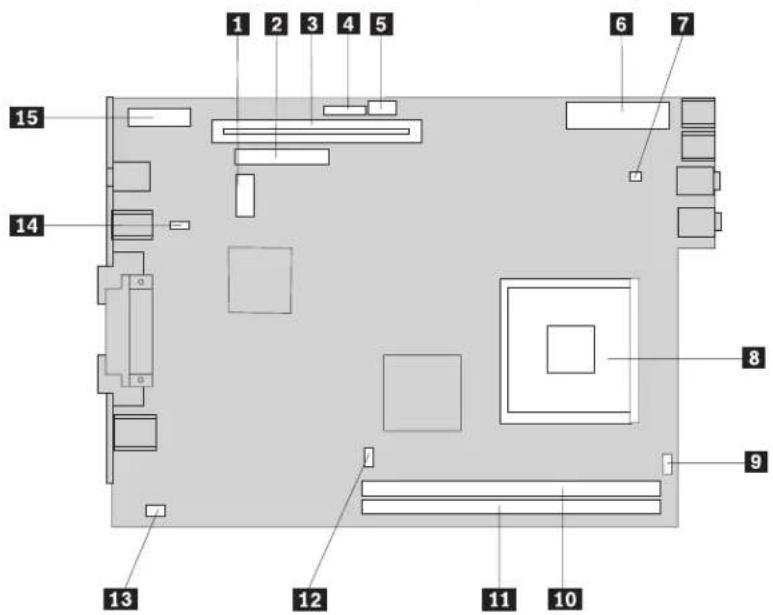
text_image
1 2 3 4 5 6 7 15 14 8 9 13 12 11 101 SATA connector (hard drive cable)
2 IDE connector (optical bay cable)
3 PCI riser connector
4 Front panel connector
5 12v power connector
6 Power connector
7 Front fan connector
8 Microprocessor
9 Speaker connector
10 Memory connector 1
11 Memory connector 2
12 Microprocessor fan connector
13 Rear fan connector
14 Clear CMOS/Recovery jumper
15 Battery
Installingmemory
Your computer has two connectors for installing dual inline memory modules (DIMMs) that provide up to a maximum of 2.0 GB of system memory.
When installing memory modules, the following rules apply:
- Use 184-pin double data rate synchronous dynamic random access memory (DDR2SDRAM).
- Use 128 MB, 256 MB, 512 MB or 1.0 GB memory modules in any combination.
Note: Only DDR2 SDRAM memory modules can be used.
To install a memory module:
-
Open the computer cover. See "Opening the cover" on page 10
-
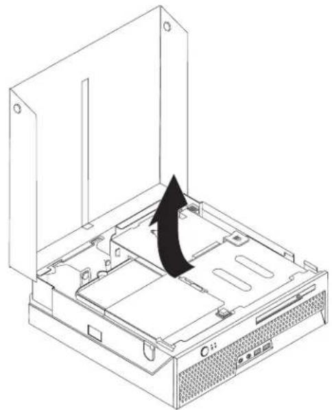
Pivot the drive bay assembly upward to gain access to the system board.
natural_image
Isometric line drawing of a computer chassis with an open lid and internal components, no text or symbols present.-
Locate the memory connectors. See "Identifying parts on the system board" or page11.
-
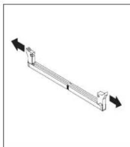
Open the retaining clips.
natural_image
Pure mechanical lever diagram without any text, numbers, or symbols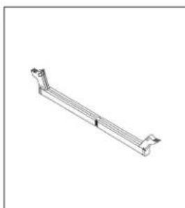
natural_image
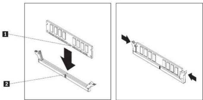
Technical line drawing of a mechanical bracket or support structure (no text or symbols)- Make sure that the notch 1 on the memory module aligns correctly with the connector key 2 on the system board. Push the memory module straight down into the connector until the retaining clips close.
text_image
Technical diagram showing two views of a RAM module with labeled components and directional arrows indicating assembly or movement.What to do next:
• To work with another option, go to the appropriate section.
- To complete the installation, go to "Closing the cover and connecting the cables" on page 20.
Installing a PCI adapter
This section provides information and instructions for installing a PCI adapter. Your computer has a riser card with one PCI expansion connector.
To install an adapter:
-
Open the computer cover. See "Opening the cover" on page 10.
-
Pivot the drive bay assembly upward to gain access to the system board.
natural_image
Isometric line drawing of a computer chassis with an open lid and internal components, no text or symbols present.-
Locate the cable clip. See "Locating components" on page 11.
-
Remove all cables from the cable clip.
-
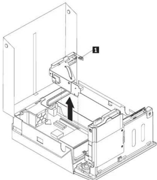
Pull upward on the blue handle provided to remove the PCI riser from the computer.
natural_image
Technical line drawing of an open electronic device casing with internal components and a black arrow indicating a component (no text or symbols present)-
Pivot the adapter latch 1 upward then remove the cover for the expansion connector.
-
Remove the adapter from its static-protective package.
-
Install the adapter into the expansion connector in the PCI riser.

natural_image
Technical line drawing of a mechanical assembly with a black arrow indicating a specific component (no text or symbols present)-
Pivot the adapter latch 1 down to retain the adapter.
-
Reinstall the PCI riser and the adapter.
What to do next:
• To work with another option, go to the appropriate section.
- To complete the installation, go to "Closing the cover and connecting the cables" on page 20.
Installing an optical drive
This section provides information and instructions for installing optical drives. You can install an optical drive to read other types of media, such as CD drives and DVDdrives.
Note: These different drives are also referred to as integrated drive electronics (IDE)drives.
When you install an optical drive, it is important to note the type of drive that you are installing.
To install an optical drive, do the following:
- Open the computer cover. See "Opening the cover" on page 10
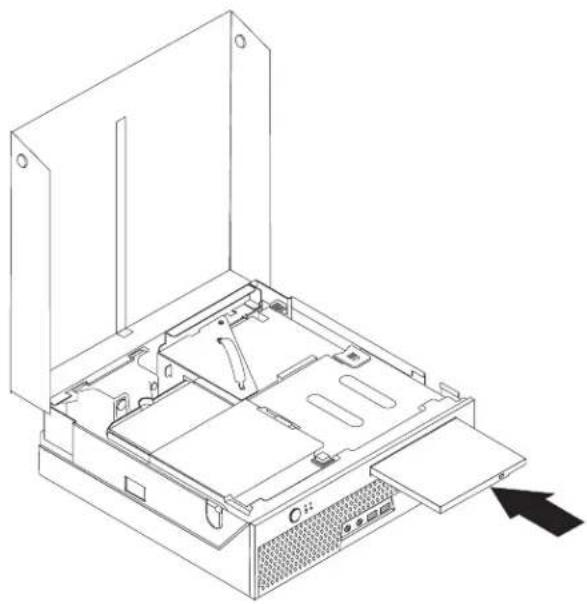
- Push the optical drive eject button to remove the panel from the bezel. See "Locating components" on page 11.
- Slide the optical drive in the front of the computer until it is locked into position.
natural_image
Technical line drawing of an open computer case with internal components and a black arrow pointing to a component (no text or symbols)What to do next:
• To work with another option, go to the appropriate section.
- To complete the installation, go to "Closing the cover and connecting the cables" on page 20.
Securityfeatures
To help prevent hardware theft and unauthorized access to your computer, several security options are available. In addition to a physical lock, unauthorized use of your computer can be prevented by a software lock that locks the keyboard until a correct password is typed in.
Make sure that any security cables you install do not interfere with other computer cables.
Integratedcablelock
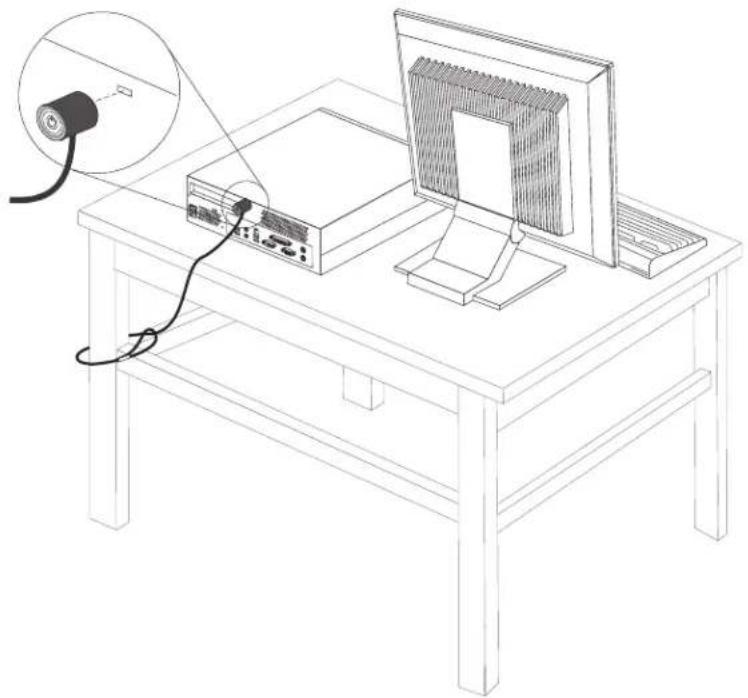
With an integrated cable lock (sometimes referred to as a Kensington lock), you can secure your computer to a desk, table, or other non-permanent fixture. The cable lock attaches to a security slot at the rear of your computer and is operated with a key. The cable lock also locks the buttons used to open the cover. This is the same type of lock used with many laptop computers. You can order a cable lock directly from Lenovo. Go to http://www.lenovo.com/support and search on Kensington.
natural_image
Line drawing of a desktop computer setup with monitor, tower, and cable (no text or symbols)Passwordprotection
To deter unauthorized use of your computer, you can use the Setup Utility program to set a password. When you turn on your computer you are prompted to type the password to unlock the keyboard for normal use.
What to do next:
• To work with another option, go to the appropriate section.
- To complete the installation, go to "Closing the cover and connecting the cables" on page 20.
Changingthebattery
Your computer has a special type of memory that maintains the date, time, and settings for built-in features, such as parallel-port assignments (configuration). A battery keeps this information active when you turn off the computer.
The battery normally requires no charging or maintenance throughout its life; however, no battery lasts forever. If the battery fails, the date, time, and configuration information (including passwords) are lost. An error message is displayed when you turn on the computer.
Refer to "Lithium battery notice" on page x for information about replacing and disposing of the battery.
To change the battery:
-
Open the computer cover. See "Opening the cover" on page 10.
-
Pivot the drive bay assembly upward to gain access to the system board.
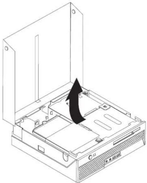
natural_image
Isometric line drawing of a computer chassis with an open lid and internal components, showing a black arrow indicating rotation (no text or symbols)-
Locate the PCI riser. See "Locating components" on page II.
-
Lift the PCI riser up to gain access to the battery. See "Installing a PCI adapter" on page 14.
-
Locate the battery. See "Identifying parts on the system board" on page 11.
-
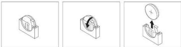
Remove the old battery.
natural_image
Three technical diagrams showing mechanical components with arrows indicating motion, no text or symbols present.- Install the new battery.

natural_image
Three technical diagrams showing mechanical components with no visible text or symbols-
Replace the PCI riser.
-
Close the computer cover, and plug in the power cord. See "Closing the cover and connecting the cables" on page 20.
Note: When the computer is turned on for the first time after battery replacement, an error message might be displayed. This is normal after replacing the battery.
-
Turn on the computer and all attached devices.
-
Use the Setup Utility program to set the date and time and any passwords. See Chapter 2, "Using the Setup Utility program," on page 21
Erasing a lost or forgotten password (clearing CMOS)
This section applies to lost or forgotten passwords. For more information about lost or forgotten passwords, see the ThinkVantage Productivity Center program on yourdesktop.
Note: If you are enrolled in the Hardware Password Reset program, refer to "Resetting the hard disk drive and power-on password" on page 23 to reset your password. If you do clear CMOS or restore Setup Utility defaults, you will have to re-enroll in the Hardware Password Reset program.
To erase a forgotten password:
- Turn off the computer and any attached devices, such as printers, monitors, and external drives.
- Unplug all power cords from electrical outlets, and open the computer cover. See "Opening the cover" on page 10.
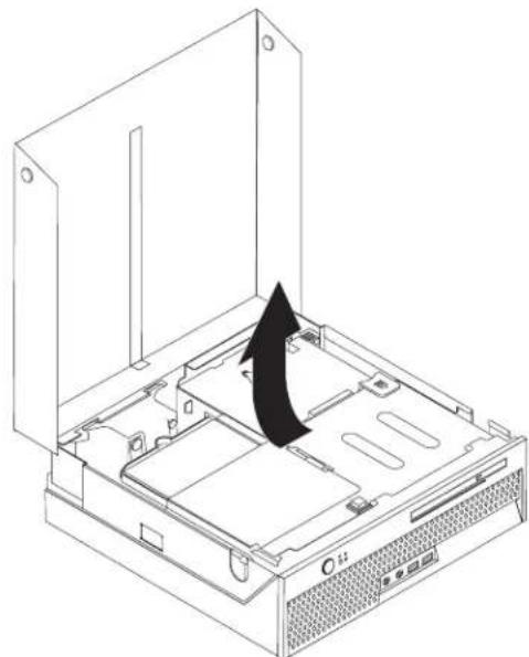
- Pivot the drive bay assembly upward to gain access to the system board.
natural_image
Isometric line drawing of a computer tower case with an arrow indicating rotation or movement (no text or symbols)- Locate the PCI riser. See "Locating components" on page 11
- Lift the PCI riser up to gain access to the Clear CMOS/Recovery jumper. See "Installing a PCI adapter" on page 14
- Locate the Clear CMOS/Recovery jumper on the system board. See "Identifying parts on the system board" on page 11
- Move the jumper from the standard position (pins 1 and 2) to the maintenance or configure position (pins 2 and 3).
-
Close the computer cover and connect the power cord. See "Closing the cover and connecting the cables" on page 20.
-
Restart the computer, leave it on for approximately 10 seconds. Turn off the computer by holding the power switch for approximately 5 seconds. The computer will turn off.
-
Repeat steps 2 through 6 on page 19
-
Move the jumper back to the standard (pins 1 and 2).
-
Replace the PCI riser.
-
Close the computer cover and connect the power cord. See "Closing the cover and connecting the cables."
Closing the cover and connecting the cables
After working with options, you need to install any removed parts, close the computer cover, and reconnect any cables, including telephone lines and power cords. Also, depending on the option that is installed, you might need to confirm the updated information in the Setup Utility program.
To close the computer cover and connect cables to your computer:
- Ensure that all components have been reassembled correctly and that no tools or loose screws are left inside your computer.
- Clear any cables that might impede the replacement of the cover.
- Lower the drive bay assembly.
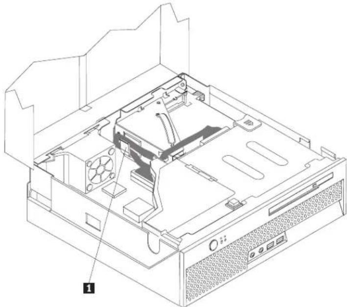
- Make sure all cables are routed correctly through the cable clip 1.
natural_image
Isometric line drawing of a computer tower internal structure showing CPU socket, drive bays, and ventilation slots (no text or labels)- Close the computer cover.
- Install any locking devices such as a cable lock as necessary.
- If your computer is being placed in the vertical position, attach the floor stand. Attention: To prevent overheating and possible component damage, always attach the floor stand when placing the computer in the vertical position.
- Reconnect the external cables and power cords to the computer. See "Locating the connectors on the rear of your computer" on page 8.
- To update the configuration, see Chapter 2, "Using the Setup Utility program," onpage21.
Chapter 2. Using the Setup Utility program
The Setup Utility program is stored in the electrically erasable programmable read-only memory (EEPROM) of your computer. The Setup Utility program is used to view and change the configuration settings of your computer, regardless of which operating system you are using. However, the operating-system settings might override any similar settings in the Setup Utility program.
Starting the Setup Utility program
To start the Setup Utility program, do the following:
- If your computer is already on when you start this procedure, shut down the operating system and turn off the computer.
- While turning on your computer, repeatedly press and release the F1 key to enter the Setup Utility program.
Note: If a user password or an administrator password has been set, the configuration settings in the Setup Utility program menu cannot be changed without a password. See "Using passwords" for more information.
The Setup Utility might start automatically when POST detects that hardware has been removed or new hardware has been installed in your computer.
Viewing and changing settings
The Setup Utility program menu lists items that identify system configuration topics.
When working with the Setup Utility program menu, you must use the keyboard. The keys used to perform various tasks are displayed at the bottom of each screen.
Exiting from the Setup Utility program
When you finish viewing or changing settings, press Esc to return to the Setup Utility program menu (you might have to press Esc several times). If you want to save the new settings, select Save Settings before you exit. Otherwise, your changes will not be saved.
Usingpasswords
By using the Setup Utility program, you can set passwords to prevent unauthorized persons from gaining access to your computer and data. The following types of passwords are available:
- User Password
- Administrator Password
• IDE Drive User Password
• IDE Drive Master Password
You do not have to set any passwords to use your computer. However, if you decide to set any passwords, read the following sections.
Passwordconsiderations
A password can be any combination of up to twelve characters (a-z and 0-9) and symbols. For security reasons, it is a good idea to use a strong password that cannot be easily compromised. Strong passwords typically adhere to the following rules:
• Have at least eight characters in length
- Contain at least one alphabetic character, one numeric character, and one symbol
- Contain at least one of the following symbols: , . / ` ; ' []
- You can also use the space bar
- Setup Utility program and hard disk drive passwords are not case sensitive
• Not be your name or your user name
• Not be a common word or a common name
- Be significantly different from your previous password
If you are setting any of the various types of passwords on your computer, you should read and understand the following information:
- If you type an incorrect password, you will see an error message. If you type an incorrect password three consecutive times, you must turn the computer off and startagain.
- If you set both a User Password and an IDE Drive User Password to the same string, you will be prompted for the password only once when you turn on your computer.
- Do not move an IDE hard disk drive to another computer if an IDE Drive User Password has been set unless that computer also supports the IDE Drive User password.
- If your computer is connected to a local area network (LAN), the Wake on LAN feature will not work unless both a User Password and an IDE Drive User Password are set using the same password.
UserPassword
When a User Password is set, the user is prompted to type a valid password each time the computer is turned on. The computer cannot be used until a valid password is typed from the keyboard.
AdministratorPassword
Setting an Administrator Password deters unauthorized persons from changing configuration settings. If you are responsible for maintaining the settings of several computers, you might want to set an Administrator Password.
After you set an Administrator Password, a password prompt is displayed each time you try to access the Setup Utility program.
If both the user and administrator passwords are set, you can type either password. However, to change any configuration settings, you must use your administratorpassword.
IDE Drive User Password
The IDE Drive User Password is used to protect the data on the IDE hard disk drive(s). When this password is set, you are prompted to type a valid password
before any hard disk drive can be used. This prompt is displayed each time you turn on your computer. If your computer has multiple hard disk drives, they all must use the same password.
Attention
If an IDE Drive User Password is set but no IDE Drive Master Password is set, there is no recovery in the event that the IDE Drive User Password is lost or forgotten. The hard disk drive must be replaced. See "IDE Drive Master Password."
IDE Drive Master Password
The IDE Drive Master Password is used to recover use of the hard disk drive in the event that the IDE Drive User Password is lost or forgotten. Only the person who knows the IDE Drive Master password can reset the IDE Drive User Password.
Attention
Make sure that the IDE Drive Master password is stored in a safe place. If both the IDE Drive User password and the IDE Drive Master password are lost or forgotten, the IDE hard disk drive must be replaced.
If both the IDE Drive User Password and the IDE Drive Master Password are to be set, the IDE Drive Master Password must be set before setting the IDE Drive User Password.
Setting, changing, and deleting a password
To set, change, or delete a password, do the following:
Note: A password can be any combination of up to twelve characters (A-Z, a-z, and 0-9). See "Password considerations" on page 22 for more information.
-
Start the Setup Utility program (see Chapter 2, "Using the Setup Utility program," on page 21).
-
From the Setup Utility program menu, select Security.
-
Select Set Passwords. Read the information displayed on the right side of the screen.
Resetting the hard disk drive and power-on password
Note: To enroll in password reset, refer to the ThinkVantage Create Rescue Media featureunderWindows.
To reset the hard disk drive and power-on password, do the following:
-
Start the Setup Utility program (see Chapter 2, "Using the Setup Utility program," on page 21).
-
From the Setup Utility program menu, select Security.
-
Select Set Passwords.
-
Select Password Reset Service and select the desired setting. Read the information displayed on the right side of the screen.
Using Security Profile by Device
Security Profile by Device is used to enable or disable user access to the IDE controller.
When this feature is set to Disable, all devices connected to the IDE controller (such as hard disk drives or the CD-ROM drive) are disabled and will not be displayed in the system configuration.
To set Security Profile by Device, do the following:
- Start the Setup Utility program (see Chapter 2, "Using the Setup Utility program," on page 21).
- From the Setup Utility program menu, select Security.
- Select Security Profile by Device and press Enter.
- Select the desired setting and press Enter.
- Return to the Setup Utility program menu and select Exit and then Save Settings.
Using IDE Drives Setup
In addition to listing the different IDE devices, there are options for configuring the serial and parallel IDE controllers.
Parallel ATA
This setting allows the user to disable one or both of the parallel IDEcontrollers.
Serial ATA
Native Mode Operation
This setting allows the user to disable the serial ATA controller.
This setting is only available when the serial ATA controller is enabled. This allows the user to specify whether the parallel and serial ATA controllers will operate in "legacy" or "native" mode. By default, they will operate in native mode unless both parallel ATA controllers are populated and a serial ATA drive is present. Then the serial ATA drive will become "native" mode. The user can select Automatic or the serial ATA controller to run in "native" mode. However, running in "native" mode might not work with older operating systems.
To configure IDE Drives Setup, do the following:
- Start the Setup Utility program (see "Starting the Setup Utility program" or page21).
- From the Setup Utility program menu, select Devices.
- Select IDE Drives Setup and press Enter.
- Select the desired devices and settings and press Enter.
- Return to the Setup Utility program menu and select Exit and then Save Settings.
Selecting a startup device
If your computer does not start up (boot) from a device such as the CD-ROM, diskette, or hard disk as expected, use one of the following procedures to select a startupdevice.
Selecting a temporary startup device
Use this procedure to startup from any boot device.
Note: Not all CDs and hard disks are startable (bootable).
- Turn off your computer.
- While turning on your computer, repeatedly press and release the F12 key to enter the Startup Device Menu.
- Select the desired startup device from the Startup Device Menu and press Enter to begin.
Note: Selecting a startup device from the Startup Device Menu does not permanently change the startup sequence.
Changing the startup sequence
To view or change the primary or automatic power-on startup sequence, do the following:
- Start the Setup Utility program (see Chapter 2, "Using the Setup Utility program," on page 21).
- Select Startup.
- Select Startup Sequence. See the information displayed on the right side of the screen.
- Select the devices for the Primary Startup Sequence, the Automatic Startup Sequence, and the Error Startup Sequence.
- Select Exit from the Setup Utility menu and then Save Settings or Save and exit the Setup Utility.
If you have changed these settings and want to return to the default settings, select Load Default Settings on the Exit menu.
Appendix A. Updating system programs
This appendix contains information about updating system programs and how to recover from a POST/BIOS update failure.
Systemprograms
System programs are the basic layer of software that is built into your computer. They include the power-on self-test (POST), the basic input/output system (BIOS) code, and the Setup Utility program. POST is a set of tests and procedures that is performed each time you turn on your computer. BIOS is a layer of software that translates instructions from other layers of software into electrical signals that the computer hardware can understand. You can use the Setup Utility program to view and change the configuration and setup of your computer.
Your computer system board has a module called electrically erasable programmable read-only memory (EEPROM, also referred to as flash memory). You can easily update POST, BIOS, and the Setup Utility program by starting your computer using a flash update diskette or by running a special update program from your operating system.
Lenovo might make changes and enhancements to the system programs. When updates are released, they are available as downloadable files on the World Wide Web (see the Quick Reference). Instructions for using the system program updates are available in a .txt file that is included with the update files. For most models, you can download either an update program to create a system-program-update (flash) diskette or an update program that can be run from the operating system.
Updating (flashing) BIOS from a diskette or CD-ROM
Note: An optional USB diskette drive may be required to update (flash) BIOS from adiskette.
- Insert a system program update (flash) diskette or CD-ROM into the diskette drive or optical drive. System program updates are available at http://www.lenovo.com/support on the World Wide Web.
Note: If you are inserting a CD-ROM into the optical drive, make sure that the computer is turned on.
- Turn on the computer. If it is on already, you must turn it off and back on again. The update begins.
- When you are prompted to select a language, press the number on your keyboard which corresponds to the language then press Enter
- When prompted to change the serial number, press Y.
- Type the seven character serial number of your computer then press Enter.
- When prompted to change the machine type/model, press Y.
- Type in the seven character machine type/model of your computer then press Enter.
- Follow the instructions on the screen to complete the update.
Updating (flashing) BIOS from your operating system
Note: Due to constant improvements being made to the Lenovo Web site, Web page content (including the links referenced in the following procedure) is subjecttochange.
- From your browser, type http://www.lenovo.com/support in the address field andpressEnter.
- Locate the Downloadable files for your machine type as follows:
a. In the Use Quick path field, type in your machine type and click Go.
b. Under Browse by product, click Continue.
c. Under Important information, click Downloads and drivers.
d. Under the BIOS category, click Flash BIOS update.
e. Click the .txt file that contains the Installation instructions for flash BIOS update (Flash from operating system version).
-
Print these instructions. This is very important since they are not on the screen after the download begins.
-
From your browser, click Back to return to the list of files. Carefully follow the printed instructions to download, extract, and install the update.
Recovering from a POST/BIOS update failure
If power to your computer is interrupted while POST/BIOS is being updated (flash update), your computer might not restart correctly. If this happens, perform the following procedure (also known as a Boot-block Recovery):
- Turn off the computer and any attached devices, such as printers, monitors, and external drives.
- Unplug all power cords from electrical outlets, and open the computer cover. See "Opening the cover" on page 10
- Locate the Clear CMOS/Recovery jumper on the system board. See "Identifying parts on the system board" on page 11
- If necessary, refer to Installing adapters to remove any adapters that impede access to the Clear CMOS/Recovery jumper.
- Move the jumper from the standard position (pins 1 and 2) to pins 2 and 3.
- Replace the computer cover. See "Closing the cover and connecting the cables" on page 20.
- Reconnect the power cords for the computer and monitor to electrical outlets.
- Insert the POST/BIOS update (flash) diskette into drive A, and turn on the computer and the monitor.
- After the update session is completed, there will be no video and the series of beeps will end and the system will automatically turn off. Remove the diskette from the diskette drive, and turn off the computer and monitor.
- Repeat steps 2 through 4.
- Replace the Clear CMOS/Recovery jumper to its original position.
- Replace any adapters that were removed.
- Replace the computer cover and reconnect any cables that were disconnected.
- Turn on the computer to restart the operating system.
Appendix B. Cleaning the mouse
This appendix provides instructions on how to clean your mouse. The procedure will be different depending on which type of mouse you have.
Cleaning an optical mouse
If you experience some problems with your optical mouse, check the following:
- Turn the mouse over and look carefully at the lens area.
a. If there is a smudge on the lens, gently clean the area with a plain cotton-tippedswab.
b. If there is some debris in the lens, gently blow the debris away from the area.
- Check the surface on which you are using the mouse. If you have a very intricate picture or pattern beneath the mouse it is difficult for the digital signal processor (DSP) to determine changes in the mouse position.
Cleaning a mouse with a ball
If the pointer on the screen does not move smoothly with the mouse, you might need to clean the mouse.
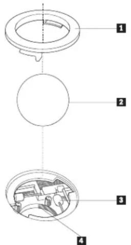
Note: The following illustration might be slightly different from your mouse.
text_image
Technical diagram showing a mechanical assembly with four labeled parts, likely illustrating a gear or component assembly.1 Retainer ring
2 Ball
3 Plastic rollers
4 Ballcage
To clean a mouse with a ball:
- Turn off your computer.
-
Turn the mouse over, with the top side down, and look carefully at the bottom. Twist the retainer ring 1 to the unlocked position to remove the ball.
-
Place your hand over the retainer ring and ball 2, and then turn the mouse over, top side up, so that the retainer ring and ball fall out into your hand.
- Wash the ball in warm, soapy water then dry it with a clean cloth. Blow air carefully into the ball cage 4 to dislodge dust and lint.
- Look for a build up of dirt on the plastic rollers 3 inside the ball cage. This build up usually appears as a stripe running across the middle of the rollers.
- If the rollers are dirty, clean them by using a cotton swab soaked in isopropyl (rubbing) alcohol. Turn the rollers with your finger and continue swabbing them until all the dirt is removed. Be sure the rollers are still centered in their channels after you clean them.
- Remove any fibers from the swab that might be remaining on the rollers.
- Replace the ball and the retainer ring.
- Turn your computer back on.
Appendix C. Manual modem commands
The following section lists commands for manually programming your modem.
Commands are accepted by the modem while it is in Command Mode. Your modem is automatically in Command Mode until you dial a number and establish a connection. Commands can be sent to your modem from a PC running communication software or any other terminal devices.
All commands sent to the modem must begin with AT ^® and end with ENTER. All commands can be typed in either upper or lower case, but not mixed. To make the command line more readable, spaces can be inserted between commands. If you omit a parameter from a command that requires one, it is just like specifying a parameter of 0.
Example:
ATH[ENTER]
BasicATcommands
In the following listings, all default settings are printed in bold text.
| CommandFunction | ||
| A | Manually answer incoming call. | |
| A/ | Repeat last command executed. Do not precede A/ with AT or follow with ENTER. | |
| D_ | 0 - 9, A-D, # and * | |
| L | last number redial | |
| Ppulsedialing | ||
| Note: Pulse dialing is not supported for Australia, New Zealand, Norway, and South Africa. | ||
| Ttouch-tonedialing | ||
| W | wait for second dial tone | |
| , | pause | |
| @ | wait for five seconds of silence | |
| ! | flash | |
| ; | return to Command Mode after dialing | |
| DS=n | Dial one of the four telephone numbers (n=0-3) stored in the modem non-volatile memory. | |
| E_ | E0 | Commands are not echoed |
| E1 | Commands are echoed | |
| +++ | Escape Characters - Switch from Data Mode to Command Mode (T.I.E.S. Command) | |
| H_ | H0H1 | Force modem on-hook (hang up)Force modem off-hook (make busy)Note: H1 command is not supported for Italy |
| I_ | I0 | Display product-identification code |
| I1 | Factory ROM checksum test | |
| I2 | Internal memory test | |
| I3FirmwareID | ||
| I4ReservedID | ||
| L_ | L0 | Low speaker volume |
| L1 | Low speaker volume | |
| L2 | Medium speaker volume | |
| L3 | High speaker volume | |
| M_ | M0 | Internal speaker off |
| M1 | Internal speaker on until carrier detected | |
| M2 | Internal speaker always on | |
| M3 | Internal speaker on until carrier detected and offwhiledialing | |
| N_ | Included for compatibility only, provides no effect | |
| O_ | O0 | Return to Data Mode |
| O1 | Return to Data Mode and initiate an equalizer retrain | |
| P | Set Pulse dial as default | |
| Q_ | Q0 | Modem sends responses |
| Sr? | Read and display value in register r. | |
| Sr=n | Set register r to value n (n = 0-255). | |
| T | Set Tone Dial as default | |
| V_ | V0 | Numeric responses |
| V1Wordresponses | ||
| W_ | W0 | Report DTE speed only |
| W1 | Report line speed, error correction protocol, andDTEspeed. | |
| W2 | Report DCE speed only | |
| X_ | X0 | Hayes Smartmodem 300 compatible responses/blinddialing. |
| X1 | Same as X0 plus all CONNECT responses/blinddialing | |
| X2 | Same as X1 plus dial tone detection | |
| X3 | Same as X1 plus busy detection/blind dialing | |
| X4 | All responses and dial tone and busy signal detection | |
| Z_ | Z0 | Reset and retrieve active profile 0 |
| Z1 | Reset and retrieve active profile 1 | |
ExtendedATcommands
| CommandFunction | ||
| &C_ | &C0 | Force Carrier Detect Signal High (ON) |
| &C1 | Turn on CD when remote carrier is present | |
| &D_ | &D0 | Modem ignores the DTR signal |
| &D1 | Modem returns to Command Mode after DTR toggle | |
| &D2 | Modem hangs up, returns to the Command Mode after DTR toggle | |
| &D3 | Resets modem after DTR toggle | |
| &F_ | &F | Recall factory default configuration |
| &G_ | &G0 | Guard tone disabled |
| &G1 | Guard tone disabled | |
| &G2 | 1800 Hz guard tone | |
| &K_ | &K0 | Disable flow control |
| &K3 | Enable RTS/CTS hardware flow control | |
| &K4 | Enable XON/XOFF software flow control | |
| &K5 | Enable transparent XON/XOFF flow control | |
| &K6 | Enable both RTS/CTS and XON/XOFF flow control | |
| &M_ | &M0 | Asynchronous operation |
| &P_ | &P0 | US setting for off-hook-to-on-hook ratio |
| &P1 | UK and Hong Kong off-hook-to-on-hook ratio | |
| &P2 | Same as &P0 setting but at 20 pulses per minute | |
| &P3 | Same as &P1 setting but at 20 pulses per minute | |
| &R_ | &R0 | Reserved |
| &R1 | CTS operates per flow control requirements | |
| &S_ | &S0 | Force DSR Signal High (ON) |
| &S1 | DSR off in command mode, on in on-line mode | |
| &T_ | &T0 | Ends test in progress |
| &T1 | Perform Local Analog Loopback Test | |
| &T3 | Perform Local Digital Loopback Test | |
| &T4 | Grant Remote Digital Loopback Test request byremotemodem | |
| &T5 | Deny Remote Digital Loopback Test request | |
| &T6 | Perform a Remote Digital Loopback Test | |
| &T7 | Perform a Remote Digital Loopback Test and Self-Test | |
| &T8 | Perform Local Analog Loopback Test and Self-Test | |
| &V | &V0 | Displays Active and Stored Profiles |
| &V1 | Display Last Connection Statistics | |
| &W_ | &W0 | Stores the active profile as Profile 0 |
| &W1 | Stores the active profile as Profile 1 | |
| %E_ | %E0 | Disable auto-retrain |
| %E1 | Enable auto-retrain | |
| +MS? | Displays the current Select Modulation settings | |
| +MS=? | Displays a list of supported Select Modulation options | |
| +MS=a,b,c,e,f | Select modulation where: a=0, 1, 2, 3, 9, 10, 11, 12, 56, 64, 69; b=0-1; c=300-56000; d=300-56000; e=0-1; and f=0-1. A, b, c, d, e, f default=12, 1, 300, 56000, 0, 0. Parameter "a" specifies the modulation protocol desired where: 0=V.21, 1=V.22, 2=V.22bis, 3=V.23, 9=V.32,10=V.32bis,11=V.34, 12=V.90,K56Flex,V.34......,56=K56Flex, V.90,V.34......, 64=Bell 103, and 69=Bell 212. Parameter "b" specifies automode operations where: 0=automode disabled, 1= automode enabled with V.8/V.32 Annex A. Parameter "c" specifies the minimum connection data rate (300- 56000). Parameter "d" specifies the maximum connection rate (300-56000); Parameter "e" specifies the codec type (0= Law, and 1=A-Law). Parameter "f" specifies "robbed bit" signaling detection (0=detection disabled1=detectionenabled) | |
MNP/V.42/V.42bis/V.44commands
| CommandFunction | ||
| %C_ | %C0 | Disable MNP Class 5 and V.42bis data compression |
| %C1 | Enable MNP Class 5 data compression only | |
| %C2 | Enable V.42bis data compression only | |
| %C3 | Enable MNP Class 5 and V.42bis data compression | |
| &Q_ | &Q0 | Direct data link only (same as \N1) |
| &Q5 | V.42 data link with fallback options | |
| &Q6 | Normal data link only (same as \N0) | |
| +DS44=0, 0 | Disable V.44 | |
| +DS44=3, 0 | Enable V.44 | |
| +DS44? | Current values | |
| +DS44=? | List of support values | |
Fax Class 1 commands
| +FAE=n | Data/Fax Auto Answer |
| +FCLASS=n | Service Class |
| +FRH=n | Receive data with HDLC framing |
| +FRM=n | Receive data |
| +FRS=n | Receive silence |
| +FTH=n | Transmit data with HDLC framing |
| +FTM=n | Transmit data |
| +FTS=n | Stop transmission and wait |
Fax Class 2 commands
| +FCLASS=n | Services class. |
| +FAA=n | Adaptive answer. |
| +FAXERR | Fax error value. |
| +FBOR | Phase C data bit order. |
| +FBUF? | Buffer size (read only). |
| +FCFR | Indicate confirmation to receive. |
| +FCLASS= | Service class. |
| +FCON | Facsimile connection response. |
| +FCIG | Set the polled station identification. |
| +FCIG: | Report the polled station identification. |
| +FCR | Capability to receive. |
| +FCR= | Capability to receive. |
| +FCSI: | Report the called station ID. |
| +FDCC= | DCE capabilities parameters. |
| +FDCS: | Report current session. |
| +FDCS= | Current session results. |
| +FDIS: | Report remote capabilities. |
| +FDIS= | Current sessions parameters. |
| +FDR | Begin or continue phase C receive data. |
| +FDT= | Data transmission. |
| +FDTC: | Report the polled station capabilities. |
| +FET: | Post page message response. |
| +FET=N | Transmit page punctuation. |
| +FHNG | Call termination with status. |
| +FK | Session termination. |
| +FLID= | Local ID string. |
| +FLPL | Document for polling. |
| +FMDL? | Identify model. |
| +FMFR? | Identify manufacturer. |
| +FPHCTO | Phase C time out. |
| +FPOLL | Indicates polling request. |
| +FPTS: | Page transfer status. |
| +FPTS= | Page transfer status. |
| +FREV? | Identify revision. |
| +FSPT | Enable polling. |
| +FTSI: | Report the transmit station ID. |
Voicecommands
| #BDR | Select Baud Rate |
| #CID | Enable Caller ID detection and reporting format |
| #CLS | Select Data, Fax or Voice/Audio |
| #MDL? | Identify Model |
| #MFR? | Identify Manufacturer |
| #REV? | Identify Revision Level |
| #TL | Audio output transmit level |
| #VBQ? | Query Buffer Size |
| #VBS | Bits per sample (ADPCM or PCM) |
| #VBT | Beep Tone Timer |
| #VCI? | Identify Compression Method |
| #VLS | Voice line select |
| #VRA | Ringback goes away timer |
| #VRN | Ringback never came timer |
| #VRX | Voice Receive Mode |
| #VSDB | Silence deletion tuner |
| #VSK | Buffer skid setting |
| #VSP | Silence detection period |
| #VSR | Sampling rate selection |
| #VSS | Silence deletion tuner |
| #VTD | DTMF tone reporting capability |
| #VTM | Enable timing mark placement |
| #VTS | Generate tone signals |
| #VTX | Voice transmit mode |
AttentionSwitzerlandUser:
If your Swisscom phone line does not have Taxsignal switched OFF, modem function may be impaired. The impairment may be resolved by a filter with the following specifications:
TelekomPTTSCR-BE
Taximpulssperrfilter-12kHz
PTTArt.444.112.7
Bakom93.0291.Z.N
Appendix D. Customer replaceable unit (CRU) parts list
For your computer, the following parts are designated customer replaceable unit (CRU) parts. Refer to the warranty section of your Quick Reference for more information.
Note: Use only the parts provided by Lenovo.
Tier1CRUs
Adaptercards
Harddiskdrives
Keyboards
Memory
Opticaldrives
Mouse
Speakers
Floppydiskettedrive
Tier2CRUs
Microprocessor
Heatsink
Powersupply
Systemboard
AppendixE.Notices
Lenovo may not offer the products, services, or features discussed in this document in all countries. Consult your local Lenovo representative for information on the products and services currently available in your area. Any reference to a Lenovo product, program, or service is not intended to state or imply that only that Lenovo product, program, or service may be used. Any functionally equivalent product, program, or service that does not infringe any Lenovo intellectual property right may be used instead. However, it is the user's responsibility to evaluate and verify the operation of any other product, program, orservice.
Lenovo may have patents or pending patent applications covering subject matter described in this document. The furnishing of this document does not give you any license to these patents. You can send license inquiries, in writing, to:
Lenovo (United States), Inc.
500 Park Offices Drive, Hwy. 54
Research Triangle Park, NC 27709
U.S.A.
Attention: Lenovo Director of Licensing
LENOVO GROUP LTD. PROVIDES THIS PUBLICATION "AS IS" WITHOUT WARRANTY OF ANY KIND, EITHER EXPRESS OR IMPLIED, INCLUDING, BUT NOT LIMITED TO, THE IMPLIED WARRANTIES OF NON-INFRINGEMENT, MERCHANTABILITY OR FITNESS FOR A PARTICULAR PURPOSE. Some jurisdictions do not allow disclaimer of express or implied warranties in certain transactions, therefore, this statement may not apply to you.
This information could include technical inaccuracies or typographical errors. Changes are periodically made to the information herein; these changes will be incorporated in new editions of the publication. Lenovo may make improvements and/or changes in the product(s) and/or the program(s) described in this publication at any time without notice.
The products described in this document are not intended for use in implantation or other life support applications where malfunction may result in injury or death to persons. The information contained in this document does not affect or change Lenovo product specifications or warranties. Nothing in this document shall operate as an express or implied license or indemnity under the intellectual property rights of Lenovo or third parties. All information contained in this document was obtained in specific environments and is presented as an illustration. The result obtained in other operating environments may vary.
Lenovo may use or distribute any of the information you supply in any way it believes appropriate without incurring any obligation to you.
Any references in this publication to non-Lenovo Web sites are provided for convenience only and do not in any manner serve as an endorsement of those Web sites. The materials at those Web sites are not part of the materials for this Lenovo product, and use of those Web sites is at your own risk.
Any performance data contained herein was determined in a controlled environment. Therefore, the result obtained in other operating environments may
vary significantly. Some measurements may have been made on development-level systems and there is no guarantee that these measurements will be the same on generally available systems. Furthermore, some measurements may have been estimated through extrapolation. Actual results may vary. Users of this document should verify the applicable data for their specific environment.
Televisionoutputnotice
The following notice applies to models that have the factory-installed television-outputfeature.
This product incorporates copyright protection technology that is protected by method claims of certain U.S. patents and other intellectual property rights owned by Macrovision Corporation and other rights owners. Use of this copyright protection technology must be authorized by Macrovision Corporation, and is intended for home and other limited viewing uses only unless otherwise authorized by Macrovision Corporation. Reverse engineering or disassembly is prohibited.
Trademarks
The following terms are trademarks of Lenovo in the United States, other countries, or both:
Lenovo
ThinkCentre
ThinkVantage
The following terms are trademarks of International Business Machines Corporation in the United States, other countries, or both:
IBM (used under license)
WakeonLAN
Microsoft and Windows are trademarks of Microsoft Corporation in the United States, other countries, or both.
Intel, Celeron, and Pentium are trademarks of Intel Corporation in the United States, other countries, or both.
Linux is a trademark of Linus Torvalds in the United States, other countries, or both.
Other company, product, or service names may be trademarks or service marks of others.
Index
A
adapters
connector14
installing14
peripheral component interconnect (PCI) 5, 14
audio line in connector 9
audio line out connector 9
audio, subsystem2
B
BIOS21
boot-blockrecovery28
C
cables,connecting20
changing
Setup Utility settings 21
thebattery17
the startup sequence 25
cleaning the mouse 29
clearingCMOS19
closing the cover 20
commands
BasicAT31
ExtendedAT33
Fax Class 1 35
Fax Class 2 35
MNP/V.42/V.42bis/V.4434
Voice36
computerfeatures1
connectordescription9
connectordescriptions9
cover
closing20
opening10
Customer Replaceable Unit (CRU) list 39
D
device,drivers9
DIMMS12
downloading device drivers 9
drives
bays2
CD5
DVD5
internal1
E
electricalinput4
environment,operating4
Ethernetconnector9
H
hard disk drive recovery 23
hard disk drive security 22
heatoutput4
I
IDE device descriptions 24
informationresourcesxiii
input/output(I/O)
features2
installingoptions
adapters14
memory12
memorymodules12
opticaldrives16
securityfeatures16
K
keyboardconnector9
L
locatingcomponents11
M
memory
dual inline memory modules (DIMMs) 12
installing12
system12
memory modules, installing 12
modem
BasicATcommands31
Extended AT commands 33
Fax Class 1 commands 35
Fax Class 2 commands 35
MNP/V.42/V.42bis/V.44 commands 34
Voicecommands36
modemcommands31
mouseconnector9
N
noiselevel4
0
opening the cover 10
options
available5
external 5,7,8
internal5
P
parallelconnector9
password
administrator22
erasing19
IDE drive master 23
IDE drive user
lost or forgotten 19
protection17
setting, changing, deleting 23
user22
passwords
considerations22
PCI expansion connector (PCI) 14
PCIriser15
physicalspecifications4
planar11
power
Advanced Configuration and Power Interface (ACPI)
support2
Advanced Power Management support 2
publicationsxiii
R
recovering from a POST/BIOS update failure 28
resetting
hard disk drive password 23
power-onpassword23
S
security
features3,16
integrated cable lock 17
security profile by device 24
selecting
a startup device 24
a temporary startup device 25
serialconnector9
SetupUtility21
Starting the Setup Utility 21
static-sensitevedevices6
systemboard
connectors12
identifyingparts11
location12
memory5,12
systemprograms27
U
USBconnectors9
using
passwords21
using the Setup Utility 21
using, security profile by device 24
V
video,subsystem2
ThinkCentre.
PartNumber:39J8083
PrintedinUSA
(1P) P/N:39J8083