
LSU5VF5D - Air-conditioner LG - Free user manual and instructions
Find the device manual for free LSU5VF5D LG in PDF.


User questions about LSU5VF5D LG
0 question about this device. Answer the ones you know or ask your own.
Ask a new question about this device
Download the instructions for your Air-conditioner in PDF format for free! Find your manual LSU5VF5D - LG and take your electronic device back in hand. On this page are published all the documents necessary for the use of your device. LSU5VF5D by LG.
USER MANUAL LSU5VF5D LG
Please read this manual carefully before operating your set and retain it for future reference.
TYPE : WALL MOUNTED
For Split AC Domestic Models
P/No. MFL39754865_V3
MFL39754865
| LG 24 x 7 CALL CENTER | ||||
| 1800-180-9999 | 5757554 | www.lg.com | www.facebook.com/lghomeappliances | |
| CALL (Toll Free) | ONI (Send SMS) | CLICK | serviceindia@lge.com | www.twitter.com/LGIndiaTweets |
TABLE OF CONTENTS
3 TIPS FOR SAVING ENERGY
4 SAFETY INSTRUCTION
8 BEFORE USE
- Prior to operation
- Components
- Electrical Safety
- Using the remote control
Inserting Batteries
➢ Installing the remote control holder
Wireless Remote Control
12 BASIC FUNCTIONS
Cooling your room
Heating your room
Removing humidity
Airing your room
Adjusting the fan speed
Adjusting the air flow direction
Setting the timer
- Setting the current time
- Turning ON the air conditioner automatically at a set time
- Turning OFF the air conditioner automatically at a set time
- Cancelling the timer setting
- Setting sleep mode

CAUTION
- Contact the authorized service technician for repair or maintenance of this unit.
- Please install your air-conditioner by company authorized service franchisee / authorized service and sales dealer.
- The air conditioner is not intended for use by young children or invalids without supervision.
- Young children should be supervised to ensure that they do not play with the air conditioner.
- When the power cord is to be replaced, replacement work shall be performed by authorized personnel only, using only genuine replacement parts.
15 ADVANCED FUNCTIONS
Changing room temperature quickly Indoor air purification
- Auto Clean operation
Energy saving cooling mode
Auto operation
Dimmer
Auto Changeover
Mosquito away operation
Operating the air conditioner without the remote control
Restarting the air conditioner automatically
18 MAINTENANCE
- Cleaning the air filter
- Cleaning the anti-allergy filter
- Cleaning the plasma filter
- Cleaning the Micro Protection filter.
- Outdoor Unit
21 TROUBLESHOOTING
- Self-diagnosis function
- Before requesting service
We recommend usage of voltage stabilizer with high / low voltage cut off in areas having voltage fluctuations.
| AC TONNAGE | STABILIZER KVA(3-STEP STABILIZER) |
| 1.0 | 3 |
| 1.5 | 4 |
| 2.0 | 5 |
TIPS FOR SAVING ENERGY
Here are some tips that will help you minimize the power consumption when you use the air conditioner. You can use your air conditioner more efficiently by referring to the instructions below:
- Avoid excessive cooling. This may be harmful for your health and may consume more electricity.
- Block sunlight with blinds or curtains while you are operating the air conditioner.
- Keep doors or windows closed tightly while you are operating the air conditioner.
- Adjust the direction of the air flow vertically or horizontally to circulate indoor air.
- Speed up the fan to cool or warm indoor air quickly, in a short period of time.
- Open windows regularly for ventilation as the indoor air quality may deteriorate if the air conditioner is used for many hours.
- Clean the air filter once every 2 weeks. Dust and impurities collected in the air filter may block the air flow or reduce the cooling / dehumidification functions. (Refer page no. 19 and 20 details of owner's manual).
For your records
Staple your receipt to this page in case you need it to prove the date of purchase or for warranty purpose. Write the model number and the serial number here:
Model number :
Serial number :
You can find them on a label on the side of each unit.
Dealer's name :
Date of purchase :
IMPORTANT SAFETY INSTRUCTIONS
READ ALL INSTRUCTIONS BEFORE USING THE APPLIANCE.
Always comply with the following precautions to avoid dangerous situations and ensure peak performance of your product

WARNING
It can result in serious injury or death when the directions are ignored.

CAUTION
It can result in minor injury or product damage when the directions are ignored.

WARNING
• Installation or repairs made by unqualified persons can result in hazards to you and others.
- The information contained in the manual is intended for use by a qualified service technician familiar with safety procedures and equipped with the proper tools and test instruments.
- Failure to carefully read and follow all instructions in this manual can result in equipment malfunction, property damage, personal injury and/or death.
Power
- Unplug the power plug immediately in the event of a blackout or thunderstorm. Failure to do so may result in fire or electric shock.
- Always use a power plug and socket with a ground terminal. Failure to do so may result in electric shock or product failure.
• Install a dedicated electric outlet and circuit breaker before you use the air conditioner. Failure to do so may result in electric shock or product failure. - Do not connect the ground wire to a gas pipe, a lightning rod or a telephone ground wire. It may result in electric shock or product failure.
- Use a standard circuit breaker and fuse conforming with the rating of the air conditioner. Failure to do so may result in electric shock or product failure.
- Make sure to check that the power cable plug is not dirty, loose or broken and then only insert the plug completely. It may result in electric shock or product failure.
- Do not modify or extend the power cable. If the power cable or cord has scratches or skin peeled off or deteriorated then it must be replaced. It may result in fire or electric shock.
- Do not touch, operate or repair the air conditioner with wet hands. It may result in electric shock or product failure.
-
Make sure that the power plug is not damaged when you move the air conditioner. Failure to do so may result in electric shock or product failure.
-
Do not place a heater or other heating appliances near the power cable. It may result in fire, electric shock, or product failure.
- Make sure that the power cord is not pulled or damaged while the air conditioner is operating. Failure to do so may result in fire, electric shock, or product failure.
- Do not place any objects on the power cord. It may result in electric shock or product failure.
Installation
- Do not install the air conditioner on an unstable surface or where there may be a danger of unit falling. It may result in death, serious injury, or product failure.
- Contact an authorized service center when you install or relocate the air conditioner. Failure to do so may result in serious injury or product failure.
- Indoor/outdoor wiring connections must be secured tightly and the cable should be routed properly so that there is no force pulling the cable from the connection terminals. Improper or loose connections can cause heat generation or fire.
- Install the panel and the cover of the control box safely. Failure to do so may result in explosion or fire.
- Do not install the air conditioner near a place with a danger of explosion or fire. It may result in explosion or fire.
- Make sure that the pipe and the power cable that connect the indoor unit and the outdoor unit are not pulled tight when you install the air conditioner. Failure to do so may result in electric shock or product failure.
- Do not mix air or any gas in the system except for the specific refrigerant. If air enters the refrigerant system, it may result in an excessively high pressure that causes injury or damage to the equipment.
Dos and Don'ts
- Be sure to use only those parts which are listed in the service parts list. Never attempt to modify the equipment. It may result in death, serious injury, effect on product performance or product failure.
- Do not pull the power cord when you remove the power plug. It may result in death or electric shock.
- Discard the batteries where there is no danger of fire. Failure to do so may result in explosion or fire.
- Contact an authorized service center when the air conditioner is submerged into water due to flooding. Failure to do so may result in explosion or fire.
- Only use components that are approved by the manufacturer and do not repair or modify them. Failure to do so may result in electric shock, effect on product performance or product failure.
- Only use the refrigerant specified on the air conditioner label. Failure to do so may result in explosion or fire.
- Do not allow water to enter into the air conditioner. It may result in explosion or fire.
- Do not leave flammable substances such as gasoline, benzene and thinner near the air conditioner. It may result in explosion or fire.
- Do not use the air conditioner for an extended period of time in a small place without ventilation. Ventilate the place regularly. Failure to do so may result in explosion or fire.
- Do not touch the electrostatic filter after opening the front grille. Failure to do so may result in electric shock or product failure.
- Unplug the power plug if there is a noise, smell or smoke coming from the air conditioner. Failure to do so may result in explosion or fire.
-
Make sure to ventilate sufficiently when this air conditioner and a heating appliance such as a heater are used simultaneously. Failure to do so may result in fire, serious injury, or product failure.
-
Make sure that children do not climb up the outdoor unit or impact it. Failure to do so may result in death or product failure.
- Do not turn ON OFF the air conditioner by plugging in or unplugging the power plug. It may result in fire or electric shock.
- When there is a gas leak, before using air conditioner again contact authorized service person for verification and repair. Failure to do so may result in explosion or fire.
- Do not use the product for special purposes, such as preserving foods, works of art, etc. It is a consumer air conditioner, not a precision refrigeration system. It may result in death, fire or electric shock.
- Do not block the inlet or outlet of air flow. It may effect product performance.
- Do not insert hands or other objects through the air inlet or outlet while the air conditioner is operating. It may result in electric shock or serious injury.
- Do not expose people, animals or plants to the cold or hot wind from the air conditioner. It may result in serious injury or health complications.
- Do not drink the water drained from the air conditioner. It may result in serious health complications.
- For inner cleaning, contact an Authorized Service Center or a dealer. Do not use harsh detergent that causes corrosion or damage on the unit. Harsh detergent that causes failure or product, fire or electronic shock
Maintenance
- Turn the main power off and unplug the power plug when you clean or repair the air conditioner. Failure to do so may result in death, serious injury, or product failure.

CAUTION
Installation
- Do not install the air conditioner where there is direct sunlight. It may effect product performance.
- Safely dispose of packing materials such as screws, nails or batteries in a packing bag after installation or repair. It may result in serious injury.
- Do not install the air conditioner where it will be exposed to sea wind (salt spray) directly. It may result in product failure.
• Install the drain hose properly for smooth drainage of condensed water. Failure to do so may result in water leakage or product failure. - Install the air conditioner where the noise from the outdoor unit or the exhaust gas will not cause inconvenience to neighbours. Neighbours so may result in conflict between
- Be cautious when you unpack or install the air conditioner. Failure to do so may result in serious injury or product failure.
- Do not touch the refrigerant leakage during installation or repair. It may result in product failure.
- When transporting the equipment, there should be at least 2 or more people, or a forklift, Failure to do so may result in serious injury.
Dos & Don'ts
- Remove the batteries when the remote control is not in use for an extended period of time. Failure to do so may result in product failure.
- Make sure that the filter is installed before you operate the air conditioner. Failure to do so may effect product performance.
-
Unplug the power plug when the air conditioner is not used for an extended period of time. Failure to do so may result in product failure.
-
Follow the standards of the corresponding region or country for handling the refrigerant and the air conditioner, and for disassembling the air conditioner. Failure to do so may result in product failure.
- Do not mix the batteries for the remote control with other types of batteries or mix new batteries with used batteries. Failure to do so may result in remote failure.
- Do not recharge or disassemble the batteries. Failure to do so may result in explosion, fire or serious injury.
- Stop using the remote control if there is a battery fluid leak. If your cloth or skin is exposed to the battery fluid from a leak, wash it off with clean water. Failure to do so may result in serious injury.
- If you swallow the battery fluid from a leak, wash out the inside of your mouth thoroughly and then consult a doctor. Failure to do so may result in serious health complications.
- Do not let the air conditioner run for long time when the humidity is very high or when a door or window has been left open. Failure to do so may effect product performance or result in product failure.
Maintenance
- Do not use strong cleaning agents or solvents when you clean the air conditioner, or spray water. Use a smooth cloth. It may result in serious injury or product failure.
- Never touch the metal parts of the air conditioner when you remove the air filter. It may result in electric shock or serious injury.
- Use a sturdy stool or ladder when you clean, maintain or repair the air conditioner at a height. Failure to do so may result in serious injury.
Disposal of your old appliance (as per e-waste Rules)
- When this crossed out wheeled bin symbol is depicted on the product and its operator's manual, it means the product is covered by the e-waste Management and Handling Rules, 2011 and are meant to be recycled, dismantled, refurbished or disposed off.
2. Dos
a. The product is required to be handed over only to the authorized recycler for disposal.
b. Keep the product in isolated area, after it becomes non-functional/unrepairable so as to prevent its accidental breakage.
Don't
a. The product should not be opened by the user himself/herself, but only by authorized service personnel.
b. The product is not meant for re-sale to any unauthorized agencies/scrap dealer/ kabariwalah.
c. The product is not meant for mixing into household waste stream.
d. Do not keep any replaced spare part(s) from the product in exposed area.
-
Any disposal through unauthorized agencies/person will attract action under Environment (Protection) Act 1986.
-
Hazards of improper handling or accidental breakage
a. If batteries are disposed incorrectly, it can greatly harm the environment. The chemical by-products are hazardous. T he metals and chemicals found in batteries can mix into soil which may be hazardous to humans, plants and animals. If thrown in fire, they can cause blast and release toxic gases which may be harmful for health.
b. The refrigerant (R-22) used can be combustible at low pressure. The potential health effects of over exposure is dizziness, headache and heart irregularities.
- To locate a nearest collection centre or call for pick-up (limited area only) for disposal of this appliance, please contact Toll Free No.1800-180-9999 for details. All collection centre and pick up facilities are done by third parties with LG Electronics India Pvt. Ltd. merely as a facilitator.
For more detailed information, please visit: http://www.lg.com
Preparing for Operation
- Contact an installation specialist for installation.
- Plug in the power plug properly.
- Use a dedicated circuit breaker.
- Do not use an extension cord.
- Do not start/stop operation by plugging/unplugging the power cord.
- If the cord/plug is damaged, replace it with only an authorized replacement part.
Usage
- Being exposed to direct airflow for a long time may be hazardous to your health. Do not expose occupants, pets, or plants to direct airflow for a long time.
- Due to the possibility of oxygen deficiency, ventilate the room when using the appliance together with stoves or other heating devices.
- Do not use this air conditioner for non-specified special purpose (e.g. preserving precision devices, food, pets, plants, or art objects). Such use may damage your properties.
Cleaning and Maintenance
- Do not touch the metal parts of the unit when removing the filter. Injury can occur.
- Do not use water to clean inside the air conditioner. Exposure to water can destroy the insulation, leading to electric shock or effect product performance.
- When cleaning the unit, first make sure that the power and breaker are turned off. The fan rotates at a very high speed during operation. There is a possibility of injury if the unit's power is triggered while cleaning inner parts of the unit.
Service
For repair and maintenance, contact your authorized service dealer.
Components
Symbols used in this Manual

This symbol alerts you to the risk of electric shock.
This symbol alerts you to hazards that may cause harm to the air conditioner.

NOTE This symbol indicates special notes.
Features

WARNING
This appliance should be installed in accordance with national wiring regulations. This guide acts as a guide to help to explain product features.
Indoor unit
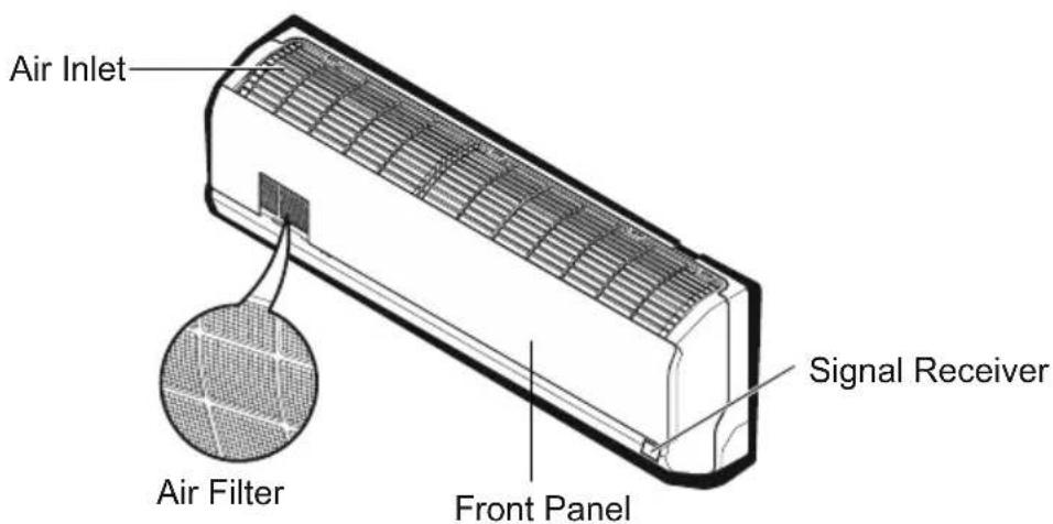
text_image
Air Inlet Signal Receiver Air Filter Front PanelOutdoor unit
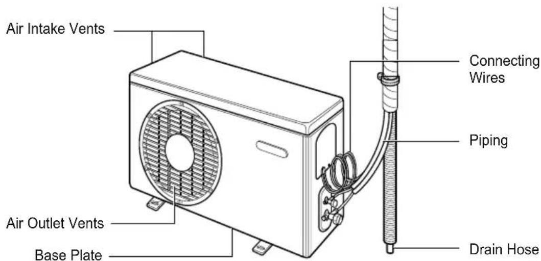
text_image
Air Intake Vents Connecting Wires Piping Air Outlet Vents Base Plate Drain HoseElectrical Safety
WARNING
• This appliance must be properly grounded.
To minimize the risk of electric shock, you must always plug into a grounded outlet.
- Do not cut or remove the grounding.
- Attaching the adapter ground terminal to the wall receptacle cover screw does not ground the appliance unless the cover screw is metal and not insulated, and the wall receptacle is grounded through the house wiring.
- If you have any doubt whether the air conditioner is properly grounded, check the wall receptacle and circuit checked by a qualified electrician.
Using the remote control
Inserting batteries
Insert batteries before using the remote control. The battery type used is AAA (1.5 V).
1 Remove the battery cover.
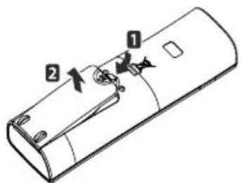
text_image
Technical diagram of a remote control casing with labeled parts 1, 2, and directional arrows indicating movement or adjustment.2 Insert the new batteries and make sure that the end terminals of the batteries are installed correctly.
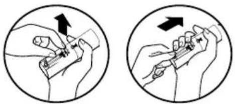
natural_image
Two circular diagrams showing hands performing a medical or laboratory procedure, with arrows indicating direction of movement (no text or symbols present)3 Re-attach the battery cover.
NOTE
If the display screen of the remote control starts to fade, replace the batteries.
Installing the remote control holder
Install the holder where there is no direct sunlight to protect the remote control.
1 Choose a safe and easily-accessible place.
2 Remove the adhesive sticker protection film from the back of the holder before attaching it to the wall.
3 Fix the holder by fastening the 2 screws firmly with a screwdriver.
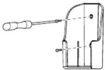
natural_image
Technical line drawing of a mechanical clamp or bracket with a handle and base (no text or symbols)4 Slide the remote control into the holder.
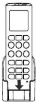
natural_image
Line drawing of a mobile phone with keypad and buttons, showing a button with an arrow (no text or symbols)Operating method
Point the remote control towards the signal receiver at the bottom of the air conditioner to operate it.
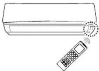
natural_image
Line drawing of a wall-mounted air conditioner with a remote control unit (no text or symbols)NOTE
- The remote control may operate other electronic devices if pointed towards them. Make sure to point the remote control towards the signal receiver of the air conditioner.
- For proper operation, use a soft cloth to clean the signal transmitter and receiver.
Using the remote control
You can operate the air conditioner more conveniently with the remote control.
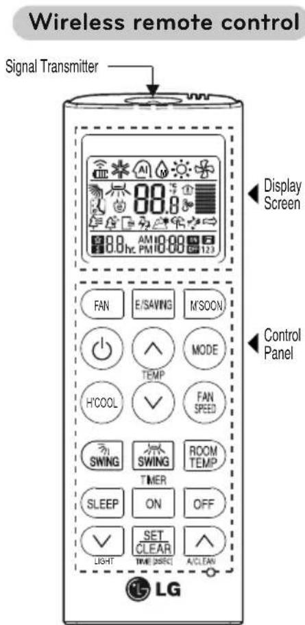
text_image
Wireless remote control Signal Transmitter Display Screen Control Panel FAN E/SAVING M'SOON TEMP H'COOL ✓ FAN SPEED SWING SWING ROOM TEMP TIMER SLEEP ON OFF LIGHT SET CLEAR A/CLEAN LG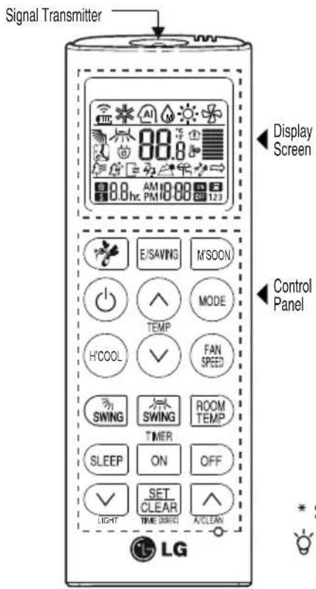
text_image
Signal Transmitter Display Screen Control Panel LG| Control panel | Display screen | Description |
| Air Circulation button: Used to circulate the room air without cooling or heating. | ||
| Mosquito Away operation button: Used to start or stop Mosquito Away operation | ||
| Sleep mode auto button: Sets the sleep mode auto operation. | ||
| Temperature adjustment buttons: Adjusts the desired temperature when cooling and heating. | ||
| - | ON/OFF button: Turns the air conditioner ON/OFF | |
| Indoor fan speed button: Adjusts the fan speed. | ||
| Operation mode selection button*: Selects the operation mode.Cooling operation (*) / Auto operation or auto changeover (AI) / Heating - operation(☀)*/ Air circulation*(☀) | ||
| Monsoon mode selection button: Use to remove excess moisture. | ||
| H'COOL button: Cools down the indoor temperature within a short period of time | ||
| Air flow direction button*:Adjusts the air flow direction. | ||
| Temperature Display: Display the room temperature. | ||
| TIMER ON OFF | Timer button: Sets the current time and the start / end time | |
| Functions button: Adjusts the time and sets the special functions.: Auto clean / ☑: Operates energy saving cooling / Turn indoor unit display ON or OFF. | ||
| Set/clear button: Sets or cancels functions and set current time. | ||
| Reset button: Initialize the remote controller settings. |
* Some functions may not be supported, depending on the model.
Symbol is for indoor unit display ON/OFF not remote controller.
BASIC FUNCTIONS
Cooling your room
(Cooling operation)
1 Press ⏻ to turn on the power.
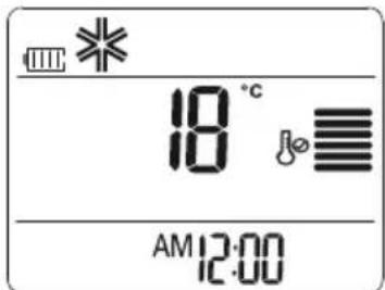
2 Press repeatedly to select the cooling operation.
- * is displayed on the display screen.
text_image
18 °C AM 12:003 Press ⬆ or ⬇ to set the desired temperature.
- The temperature range is 18^ C - 30^ C
Heating your room
(Heating operation)
1 Press Ⓤ to turn on the power.
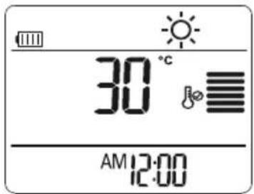
2 Press (MOREpeatedly to select the heating operation.
-☀ is displayed on the display screen.
text_image
30°C AM 12:003 Press ∧ or ∨ to set the desired temperature.
- The temperature range is 16^ C - 30^ C
NOTE
Cooling-only models do not support this function.
Removing humidity (Cooling Mode Only) (Monsoon operation)
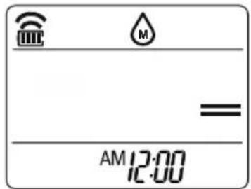
This mode removes excess moisture from environment with high humidity or in the rainy season, in order to prevent mold from setting in. This mode adjusts the room temperature and the fan speed automatically to maintain the optimal level of humidity.
1 Press ⏻ to turn on the power.
2 Press M/STO select the monsoon operation.
- M is displayed on the display screen.
text_image
AM 12:00NOTE
- In this mode you cannot adjust the room temperature, as it is adjusted automatically. Also, the room temperature is not displayed on the display screen.
- In this mode indoor unit fan and outdoor unit will be OFF intermittently.
- To Exit from Monsoon mode press MODE key or HCOOL key or FAN key
Airing your room (Air Circulation operation)
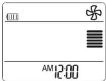
This mode only circulates the indoor air without changing the room temperature.
1 Press ⏻ to turn on the power.
2 Fan button : Press FAN turn on the air circulation operation.
- is displayed on the display screen.
text_image
AM 12:003 Press FAN SPEED to adjust the fan speed.
Adjusting the fan speed
1 Press repeatedly to adjust the fan speed.
- Select if you want natural air. The fan speed adjusts automatically.
Natural wind (CHAOS Logic)
For fresher feeling, press the INDOOR FAN SPEED SELECTION BUTTON and set to Natural wind mode (→). In this mode, the wind blows like a natural breeze by automatically changing fan speed.
Adjusting the air flow direction
1 To adjust the direction of the flow vertically, press change the air flow direction automatically.
- This function is apply for only turn SWING On/Off.
2 To adjust the direction of the flow horizontally, press change the air flow direction automatically.
- This function is apply for only turn SWING On/Off.
NOTE
- Adjusting the air flow direction horizontally may not be supported, depending on the model.
- Adjusting the air deflector arbitrarily may cause product failure.
- If you restart the air conditioner, it starts to operate with the previously set direction of air flow, so the air deflector may not match the icon displayed on the remote control. When this occurs, press
SWING or SWING to adjust the direction of the air flow again.
Setting the timer
You can use the timer function to save energy and to use the air conditioner more efficiently.
Setting the current time
1 Press and hold it for longer than 3 seconds.
- The AM/PM icon flickers at the bottom of the display screen.
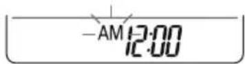
2 Press or to select. desired time.
3 Press SET to finish.
Turning ON the air conditioner automatically at a set time
1 Press ON
- The icon below flickers at the bottom of the display screen.
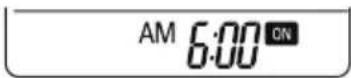
2 Press √ or to select desired time.
3 Press to finish.
4 When setting the timer, current time and ON icon are displayed on the display screen indicating that the ON TIMER is set.
Turning OFF the air conditioner automatically at a set time
1 Press OFF
- The icon below flickers at the bottom of the display screen.
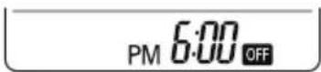
2 Press √ or to select desired time.
3 Press SET to finish.
4 When setting the timer, current time and OFF icon are displayed on the display screen indicating that the OFF TIMER is set.
NOTE
- This function may not be supported, depending on the model.
- This mode does not have auto restart feature.
Canceling the timer setting
1 Press or to select the timer setting to cancel.
2 Press SET CLEAR
- To cancel all timer settings, press SET CLEAR (The timer lamp on the air conditioner and the display will go off.)
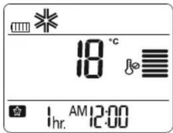
Setting sleep mode
Use the sleep mode to turn OFF the air conditioner automatically when you go to sleep.
The fan speed is set to low in sleep mode.
1 Press ⏻ to turn on the power.
2 Press SLEEP
3 Press √ or to select the hour (up to 7 hours).
4 Press SET to finish.
- 會 is displayed on the display screen in sleep mode.
text_image
18 °C Ihr. AM 12:00NOTE
- The sleep mode will operate indoor fan at super low speed in cooling mode and at low speed in heating mode for pleasant sleep In cooling mode or Monsoon mode:
The setting temperature will rise automatically two times by 1^ C over next consecutive 30 minutes (Maximum 2^ C) for a comfortable sleep.
This will be the final setting temperature as long as sleep mode is functioning.
After completion of set time unit will switch OFF automatically.
ADVANCED FUNCTIONS
The air conditioner offers some additional advanced functions.
Changing room temperature quickly
H'COOL(Himalaya)Mode
This mode allows you to cool indoor air quickly in summer
1 Press ⏻ to turn on the power.
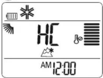
2 Press HCOOL
text_image
HC AM 12:00-In H'COOL(Himalaya)mode,30 minutes strong focused air blows out for faster cooling.
NOTE
- In Air Circulation, Auto, or Auto Changeover mode, this function cannot be used.
- During & after H'COOL mode swing function will be ON by default.
• To OFF swing function Press respective swing key. - This function may not be supported, depending on the model.
- This mode does not have auto restart feature.
Indoor air purification Auto Clean operation
In the cooling and monsoon operations, moisture is generated inside the indoor unit. Use the auto cleaning function to remove such moisture.
1 Press ⏻ to turn on the power.
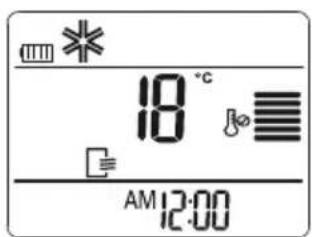
2 Press ▲
- □ is displayed on the display screen.
text_image
18 °C AM 12:00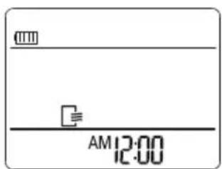
text_image
AM 12:00- If you turn off the power, the fan operates for 30 minutes and cleans the inside of the indoor unit.
NOTE
Some buttons cannot be used while the auto cleaning function is in operation.
NOTE
During Auto Clean function, "Co" will be displayed on the unit.
NOTE
Power saving lamp blink depending on the model.
Energy saving cooling mode
This mode minimizes power consumption during cooling and increases the set temperature to the optimal level for a more comfortable environment.
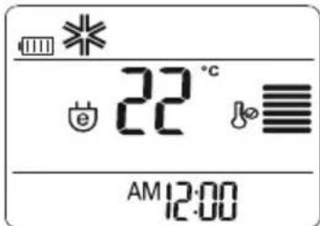
The temperature automatically sets at 22^ C if ambient temperature is below 22^ C.
The temperature maintains if ambient temperature is above 22^ C
1 Press ⏻ to turn the power on.
2 Press more repeatedly to select the cooling operation.
3 Press E/SAVING
- e is displayed on the display screen.
text_image
22°C AM 12:00NOTE
This function may not be supported, depending on the model. In Energy Saving Cooling Mode, temperature on the display of the remote controller and air conditioner can be different.
NOTE
- This function may not be supported, depending on the model.
- This mode does not have auto restart feature.
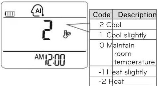
Auto operation (Optional) (Artificial intelligence)
Cooling-only models
In this mode, the fan speed and the temperature adjust automatically, based on the room temperature.
1 Press ⏻ to turn on the power.
2 Press MODE repeatedly to select auto operation.
3 Press √ or to select the desired operation code if the temperature is higher or lower than the desired temperature.
text_image
Code Description 2 Cool 1 Cool slightly 0 Maintain room temperature -1 Heat slightly -2 HeatNOTE
- In this mode, you cannot adjust the fan speed, but you can set the air deflector to rotate automatically.
- This function may not be supported, depending on the model.
Dimmer (Optional)
In Dimmer Mode Unit Display will be turned OFF completely but system will be in running state.
- Make sure that remote & Air conditioner are ON.
- Press ⬇ (∨) to activate/deactivate dimmer
function.
NOTE
Dimmer Mode will be cancelled if any key except is pressed (Power Key will turn OFF the Unit).
NOTE
This function may not be supported by Auto Restart feature (depending on selected models).
Auto Changeover (Optional)
Heat pump models
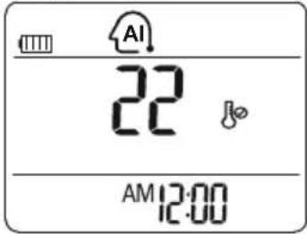
This operation is basically heating or cooling function of the air conditioner. But during this operation the controller change the operation mode automatically to keep the temperature within ±2^ with respect to the setting temperature.
1 Press ⏻ to turn on the power.
2 Press MODE repeatedly to select auto operation.
- AI is displayed on the display screen.
text_image
AI 22 AM 12:003 Press √ or ∧ to set the desired temperature.
- The temperature range is 18^ C - 30^ C
4 Press FAN SPEED repeatedly to select the fan speed.
NOTE
- This function may not be supported, depending on the model.
Mosquito Away\* Operation (Optional)
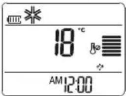
Mosquito Away is a device to radiate frequency which mosquitoes don't like.
1 Press
- To start Mosquito Away function.
text_image
* 18 °C & ? AM 12:002 Press 🎨 again to finish
NOTE
- You can use this function by pressing without turning the air conditioner ON. (In this case, Fan speed can not be changed). At this time horizontal vane will be at default position & the fan speed will be low.
- This function can be used with other function like timer, monsoon.
- This function may not be supported depending on the model.
- The Mosquito Away performance can be different depending on the customer's environment.
For detail refer Disclaimer.
Operating the air conditioner without the remote control (Forced Operation)
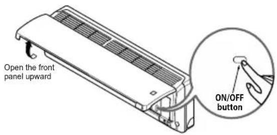
You can use the ON/OFF button of the indoor unit to operate the air conditioner when the remote control is unavailable. However, the fan speed is set to high.
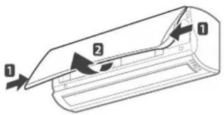
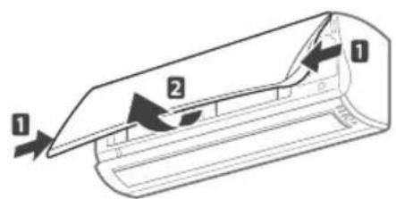
1 Open the front cover.
- Lift up both sides of the cover slightly.
text_image
Diagram of a car air duct with labeled parts 1 and 2, showing directional arrows indicating flow or movement.2 Press the On/Off button.

text_image
Open the front panel upward ON/OFF button- For cooling and heating models, the operation mode changes, depending on the room temperature.
| Cooling Model | Heat pump Model* | ||
| Room Temp.324°C 21°C | Room Temp. < 24°C Room Temp. < 21°C | ||
| Operating mode | Cooling Cooling Healthy Dehumidification Heating | ||
| Indoor FAN Speed | High High High High | ||
| Setting Temperature | 22°C 22°C 23°C 24°C | ||
If you want to stop the unit, re-press the power button.
NOTE
- This function may not be supported, depending on the model.
Restarting the air conditioner automatically
When the air conditioner is turned on again after a power failure, this function restores the previous settings. This function is a factory default setting.
Disabling auto restart (Optional)
1 Open the front cover.
- Lift up both sides of the cover slightly.
text_image
Diagram of a car air conditioner unit with labeled parts 1 and 2, showing airflow direction arrows.2 Press the On/Off button and hold it for 6 seconds.
- The unit will beep twice and the lamp will blink 8 times.
text_image
Open the front panel upward ON/OFF button- To re-enable the function, press the On/Off button and hold it for 6 seconds. The unit will beep twice and the blue lamp will blink 4 times.
NOTE
If you press and hold the On/Off button for 3 – 5 seconds instead of 6 seconds, the unit will switch to the test operation. In the test operation, the unit blows out strong air for cooling for 18 minutes and then returns to the factory default settings.
MAINTENANCE
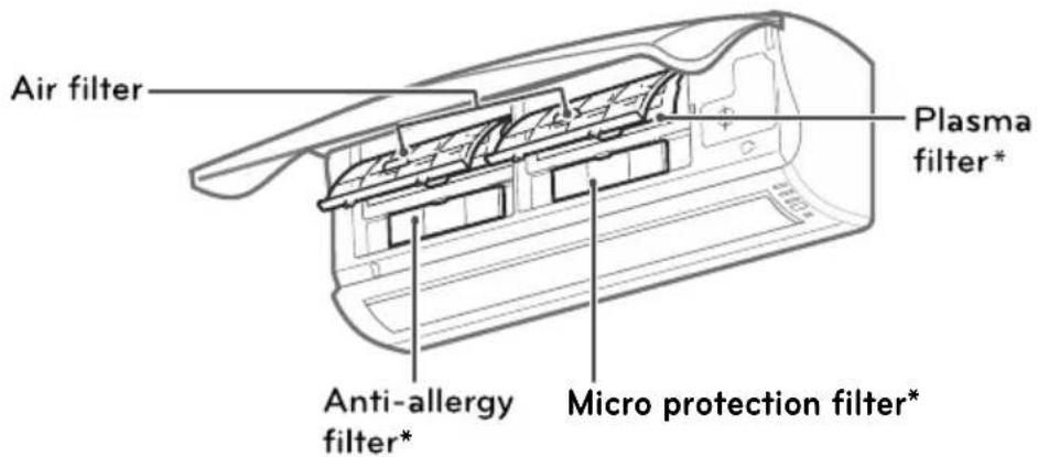
Clean the product regularly to maintain optimal performance and to prevent possible breakdown.
text_image
Air filter Plasma filter* Anti-allergy filter* Micro protection filter*| Item | Cleaning interval | Cleaning method |
| Air filter | 2 weeks | See “Cleaning air filter.” |
| Anti-allergy filter* | 3 months | See “Cleaning anti-allergy filter.” |
| Plasma filter* | 3 months | See “Cleaning the plasma filter.” |
| Micro Protection filter* | 1 month | See “Cleaning the Micro Protection filter.” |
| Indoor unit surface | Regularly | Use a soft, dry cloth. Do not use bleach or abrasives. |
| Outdoor unit | Regularly | Use soap solution to clean the heat exchanger coils and the panel vents (consult with technician). |

CAUTION
- Turn OFF the power and unplug the power cord before you perform any maintenance; otherwise it may cause electric shock.
- Never use water that is hotter than (40°C) when you clean the filters. It may cause deformation or discoloration.
- Never use volatile substances when you clean the filters. They may damage the surface of the product.

NOTE
- The location and shape of the filters may differ, depending on the model.
- Make sure to clean the heat exchanger coils of the outdoor unit regularly, as dirt collected in the coils may decrease the operational efficiency or increase energy consumption.

NOTE
- This may not be provided, depending on the model.
Cleaning the air filter
Clean the air filter once every 2 weeks or more if necessary.
1 Turn off the power and unplug the power cord.
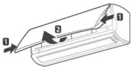
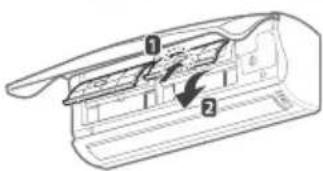
2 Open the front cover.
- Lift up both sides of the cover slightly.
text_image
Diagram of a airflow or ventilation system with labeled components 1 and 2, showing directional flow arrows.3 Hold the knob of the air filter, lift it up slightly and remove it from the unit.
text_image
Technical diagram of a mechanical component with numbered parts and directional arrows indicating flow or movement.Caution
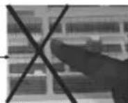
Do not press the mesh
4 Clean the filter with a vacuum cleaner or with warm water.
- If dirt is difficult to remove, wash the filter in lukewarm water with detergent.
5 Dry the filter in the shade.
Cleaning the anti-allergy filter
1 Turn off the power and unplug the power cord.
2 Open the front cover and remove the air filter (see "Cleaning air filter").
3 Pull out the anti-allergy filter and the triple filter.
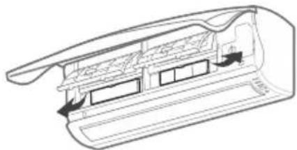
natural_image
Cross-sectional diagram of a mechanical or architectural component with internal structure and directional arrows (no text or symbols)4 Dry the filter in direct sunlight for 2 hours.
NOTE
The location and shape of the filters may differ, depending on the model.
Cleaning the plasma filter
1 Turn off the power and unplug the power cord.
2 Open the front cover and remove the air filter (see "Cleaning air filter").
3 Remove the plasma filter after 10 seconds.
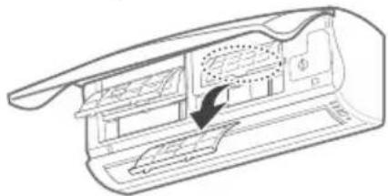
natural_image
Technical line drawing of a mechanical component with an arrow indicating a process or assembly (no text or symbols present)4 Use a vacuum cleaner to remove any dirt. - If dirt is difficult to remove, wash the filter with lukewarm water.
5 Dry the filter in the shade.
NOTE
- The location of the filters may differ, depending on the model.
- The plasma filter may not be included in some models.
Cleaning the Micro Protection Filter (Optional)
1 Turn off the power and unplug the power cord.
2 Open the front cover and remove the air filter (see "Cleaning air filter").
3 Remove the Micro Protection Filter.
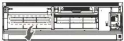
natural_image
Architectural cross-section diagram of a server room with rack, unit, and door (no text or labels)4 Use a vacuum cleaner to remove dirt,
- Do not wash the Micro Protection Filter with water because the filter can be damaged.
5 Dry the filter in the shade.

NOTE
• We suggest changing the Micro Protection Filter every 6 months.
- The location of the filters may differ, depending on the model.
- For more filters, Please contact the LG service center.
(Refer to the warranty card.)
- The feature can be changed according to type of model.
Outdoor Unit
The heat exchanger coils and panel vents of the outdoor unit should be checked regularly. If clogged with dirt or soot, the heat exchanger and panel vents may be professionally steam cleaned.

NOTE
Dirty or clogged coils will reduce the operating efficiency of the system and cause higher operating costs.
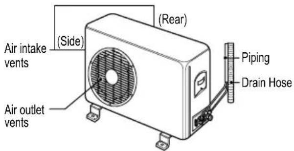
text_image
Air intake vents (Side) (Air outlet vents) (Rear) Piping Drain HoseTROUBLESHOOTING
Self-diagnosis function
This product has a built-in self-diagnosis function. If an error occurs, the lamp of the indoor unit will blink in 2 second intervals. If this occurs, contact your local dealer or call center.
Before requesting service
Please check the following before you contact the call center. If the problem persists, contact your local call center.
| Problem | Possible causes | Corrective action |
| There is a burning smell and an abrupt sound coming from the unit. | - | Turn off the air conditioner, unplug the power cord and contact the call center. |
| Water leaks from the indoor unit even when the humidity level is low. | ||
| The power cord is damaged or generating excessive heat. | ||
| A switch, a circuit breaker (safety, ground) or a fuse is not operated properly. | ||
| The air conditioner does not work. | The air conditioner is unplugged. | Check whether the power cord is plugged into the outlet. |
| A fuse is blown or the power supply is blocked. | Replace the fuse or check if the circuit breaker has tripped. | |
| A power failure has occurred. | Turn off the air conditioner when a power failure occurs. When the power is restored, wait 3 minutes, and then turn on the air conditioner. | |
| The voltage is too high or too low. | Check if the circuit breaker has tripped. | |
| The air conditioner turned off automatically at a preset time. | Press the power button again. | |
| The air conditioner does not generate cool air. | Air is not circulating properly. | Make sure that there are no curtains, blinds or furniture blocking the front of the air conditioner. |
| The air filter is dirty. | Clean the air filter once every 2 weeks. See “Cleaning Air Filter” for more information | |
| The room temperature is too high. | In summer, it may take some time to cool indoor air. In this case, select the H’COOL operation to cool indoor air quickly. | |
| Cold air is escaping from the room. | Make sure that no cold air is escaping through ventilation points in the room. | |
| The desired temperature is higher than the set temperature. | Set the desired temperature to a level lower than the current temperature. | |
| There is a heating source nearby. | Avoid using a heat generator such as an electric oven or a gas burner while the air conditioner is in operation. | |
| Air circulation operation is selected. | In the air circulation operation, air blows from the air conditioner without cooling or heating the indoor air. Switch the operation mode to the cooling operation. | |
| It is not possible to adjust the fan speed. | The auto operation, H’COOL operation or dehumidifying operation is selected. | In some operation modes, such as the H’COOL or dehumidifying operation modes, you cannot adjust the fan speed. Select an operation mode in which you can adjust the fan speed. |
| It is not possible to adjust the temperature. | The air circulation operation or H’COOL operation is selected. | In some operation modes, such as the air circulation or H’COOL mode, you cannot adjust the temperature. Select an operation mode in which you can adjust the temperature. |
| Tak-tak noise from indoor unit | Contraction or expansion of plastic components due to change in temperature | It is a natural phenomenon, and can only be reduced but not overcome completely |
Operation ranges
For Heat & Cool model, heating operation range follows the below table.
| HeatingOperation range | Outdoor temperature |
| 0~24°C |
* When the outdoor temperature drops below 0°C, heating capacity may drop slightly depending on the operation condition.
When the air conditioner is not going to be used for a long time.
When air conditioner is not going to be used for a long time.

Operate the air conditioner on Air circulation mode (Refer to page 13) for 2 to 3 hours.
• This will dry out the internal mechanisms.

Turn off the circuit breaker, and disconnect the plug.

CAUTION
Turn off the circuit breaker when the air conditioner is not going to be used for a long time. Dirt may collect and may cause a fire.

Remove the batteries from the remote control.
When the air conditioner is to be used again.

Clean the air filter and install it in the indoor unit. (Refer to page 19 for cleaning filters.)

Check that the air inlet and outlet of the indoor/outdoor unit are not blocked.
DISCLAIMER
IMPORTANT: Long term effect not tested and mosquitoes may become resistant. Mosquito species used in the test below may differ from the mosquito species of your region. This product is one of the ways to manage mosquitoes and not intended to replace other protective devices against mosquitoes.
Test Details:
A: Tested by International Institute of Biotechnology and Toxicology (IIBAT), India, According to LG internal testing method.
• Test conducted, three times at temperature of 27 ± 2^ and humidity of 60 ± 10%
- Test used two chambers size 3.5m x 2.6m x 2.2m, the chamber with the LG air conditioner assumed to be inside ("inside chamber") and the chamber without the LG conditioner assumed to be outside ("outside chamber").
- Cages (25cm ^3 ) are placed inside each chamber, connected using netted sleeves to enable the movement of the mosquitoes from one cage to another.
• One person is placed inside the chamber to attract mosquitoes
- For each test, 50 lab cultured 3-5 days old mosquitoes were placed in the cage in outside chamber; number of mosquitoes coming into the cage in inside chamber was counted every 10 minutes for 90 minutes under 2 settings:
* Control setting (low fan ON + mosquito repelling ultrasonic OFF)
* Treatment setting (low fan ON + mosquito repelling ultrasonic ON)
Test Result:
Found to repel on average 81.1% of Aedes aegypti mosquitoes. Repel rate shows percentage of mosquitoes prevented from entering the inside chamber after 90 minutes of Treatment setting compared to Control setting. Represented average of 81.1% derived from 76.9%, 84.6%, 81.8%.
B: Tested by Intertek, Korea,
According to LG internal testing method.
• Test conducted, three times at temperature of 27 ± 2^ and humidity of 60 ± 10%
- Test used two chambers size 33m^3 and 19m^3 connected by a channel made of white sheet, small chamber assumed to be outside (“outside chamber”) and the large chamber to be inside with the LG air conditioner (“inside chamber”)
• One person is placed inside the inside chamber to attract mosquitoes
- For each test, 50 lab cultured 3-5 days old mosquitoes were released into outside chamber; number of mosquitoes coming into the inside chamber was counted every 10 minutes for 90 minutes under 2 settings:
• Control setting (low fan ON + mosquito repelling ultrasonic OFF)
* Treatment setting (low fan ON + mosquito repelling ultrasonic ON)
Test Result:
Found to repel on average 72.5% of Aedes aegypti mosquitoes. Repel rate shows percentage of mosquitoes prevented from entering the inside chamber after 90 minutes of Treatment setting compared to Control setting. Represented average of 72.5% derived from 73.1%, 64.3%, 80.0%.
Results may vary in other settings, including but not limited to temperature, humidity, location, space, mosquito species, number of mosquitoes, number of persons, and operation time.
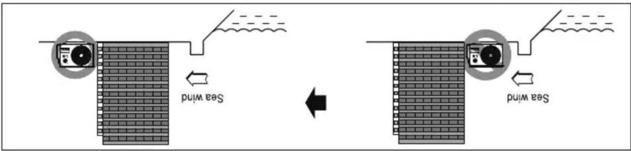
- Do not use sea water for this purpose. 2. Periods (more than once/year) cleaning of the dust or salt particles struck on the heat exchanger by using water 1. If you can't meet above guide line in the seaside installation, please contact LG Electronics for the additional accordance treatment.
3) Select a well-duried place.
- If should be strong enough like concrete to prevent the sea wind from the sea. - The height and width should be more than 150% - of the outdoor unit. - Keep more than 700mm of space between outdoor unit and the windbreak for easy air flow.
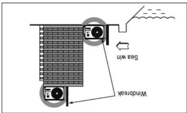
text_image
Windbreak Seat win2) In case, to install the outdoor unit on the sea-side, set up a windbreak so that outdoor unit not exposed to the sea wind.
text_image
Sea wind Sea wind1) If the outdoor unit is to be installed close to the seaside, then direct exposure to the sea wind should be avoided. Install the outdoor unit on the opposite side of the sea wind direction.
Selecting the location(Outdoor Unit)
- Air conditioners should not be installed in areas where corrosive gases, such as acid or alkaline gas, are produced.
- Do not install the product where it could be exposed to sea wind (salty wind) directly. It can result corrosion on the product. Corrosion, particularly on the condenser and evaporator, this, could cause product malfunction- tion or inefficient performance.
- If outdoor unit is installed close to the seaside, it should avoid direct exposure to the sea wind. Otherwise it needs additional anticorrosion treatment on the heat exchanger.
CAUTION
Installation guide at the seaside
the outdoor unit.
- When the low-pressure gauge reading becomes 1 to 0.5kg/cm ^2 (G(14.2 to 7.1 P.S.I.G.), fully close the gas side valve stem and then quickly turn off the unit. At that time, Pump Down has been completed and all refrigerant gas will have been collected in
cooling operation.
gas. 3. Close the liquid side service value (all the way in). 4. Turn on the units' operating switch and start the
- Connect a low-pressure gauge manifold chose to the charge port on the gas side service valve.
- Open the gas side service valve halfway and purge the air from the manifold chose using the refrigerator.
Pump Down Procedure
Be sure to perform Pump Down procedure with the unit cooling mode.
i CAVITIOn:
This is performed when the unit is to be relocated or the refrigerator circuit is serviced. Pump Down means collecting all refrigerator in the outdoor unit without loss in refrigerator gas.
PUMP DOWN
The air conditioner is now ready for use.
If the actual pressure is higher than shown, the system is most likely over-charged, and charge should be removed. If the actual pressure is lower than shown, the system is most likely undercharged, and charge should be added.
NOTE i
| Refrigerant | Outside ambient TEMP | The pressure of the gas side service valve. |
| R22 | 35°C (95°F) | 4~5kgf/cm ^2 (56.8~71.0 P.S.I.G.) |
| R410A | 35°C (95°F) | 8.5~9.5 kgf/cm ^2 (120~135 P.S.I.G.) |
condition is as below (Cooling).
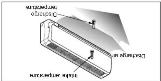
- For reference; the gas side pressure of optimum
text_image
Intake temperature Discharge temperature Discharge air(Cooling) or reversely (Heating).
- Ensure the difference between the intake temperature and the discharge is more than 8^ C.
discharge of air.
- Measure the temperature of the intake and
valve.
- Measure the pressure of the gas side service
system refrigerant charge:
Operate unit for 15\~20 minutes, then check the
C Evaluation of the performance
Tubing connection
text_image
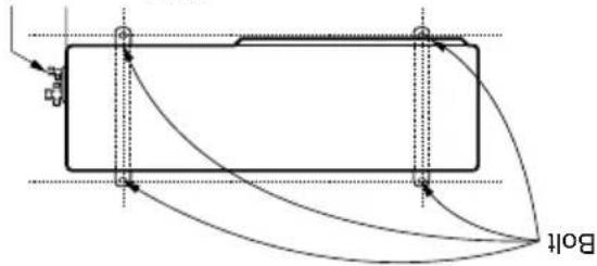
Boltanti-vibration rubber.
conveyed to the hose, secure the unit with an
In the case when the vibration of the unit is
Anchor the outdoor unit with a bolt and nut 10mm) heighty and horizontally on a concrete or rigid mount. When installing on the wall, roof or rooftop, anchor the mounting base securely with a nail or wire assuming the influence of wind and earthquake.
B Settlement of outdoor unit
time.
- Remove the batteries from the remote control if the system is not going to be used for a long
rechargeable batteries.
- Use 2 AAA(1.5volt) batteries. Do not use
NOTE i
natural_image
Illustration of three hands performing a manual task with arrows indicating direction (no text or symbols present)-
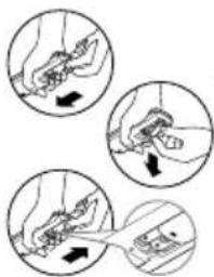
Reetach the cover by pushing it back into position.
-
Insert new batteries making sure that the (+) and (−) of battery are installed correctly.
-
Remove the battery cover by pulling it according to the arrow direction.
A Prepare remote control
are fully open.
- Check that the gas and liquid side service valves
property connected.
- Check that all tubing and wiring have been
TEST RUNNING
text_image
Vacuum pump Open Pressure gauge Manifold valve Close Outdoor unit Indoor unit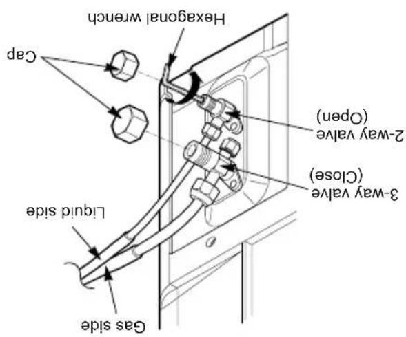
text_image
Gas side Liquid side Cap Hexagonal wrench 2-way valve (Open) 3-way valve (Close)This completes air purging with a vacuum pump. The air conditioner is now ready to test run.
■ Replace the flare nut and its bonnet on the gas side service port and fasten the flare nut securely with an adjustable wrench. This process is very important to prevent leakage from the system. ■ Replace the valve caps at both gas and liquid side service valves and fasten them light.
Turn the valve stem of gas side valve counter-cl Greenwich to fully open the valve. Loose the charge hose connected to the gas side service port slightly to release the pressure, then remove the hose.
With a service valve wrench, turn the valve stem of liquid side valve counter-clonkwise to fully open the valve.
D Finishing the job
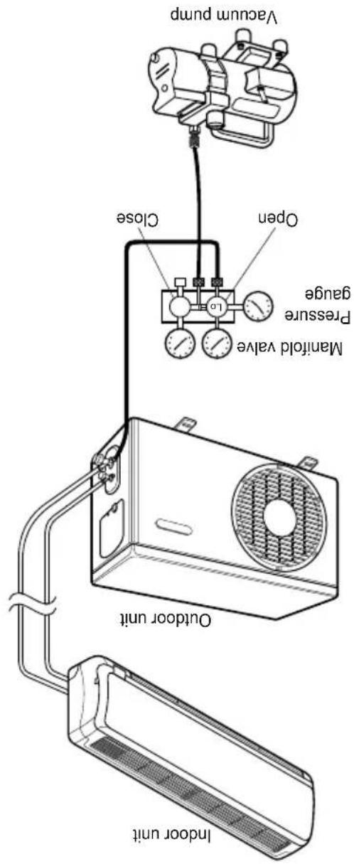
When the desired vacuum is reached, close the "Lo" know of the manifold valve and stop the vacuum pump.
| Required time for evacuation when 30 gal/hvacuum pump is used | |
| If tubing length is less than 10m (33 ft) | If tubing length is longer than 10m (33 ft) |
| 10 min. or more 15 | min. or more |
evacuation.
Connect the charge hose end described in the preceding steps to the vacuum pump to evacuate the tubing and indoor unit. Confirm the "Lo" know of the manifold value is open. Then, run the vacuum pump. The operation time for evacuation varies with tubing length and capacity of the pump. The following table shows the time required for
C Evacuation
(4) Apply a soap water or a liquid neutral detergent on the indoor unit connection or outdoor unit connections by a soft brush to check for leakage of the connecting points of the piping. (5) If bubbles come out, the pipes have leakage.
(1) Remove the caps from the 2-way and 3-way valves. (2) Remove the service-port cap from the 3-way valves. (3) To open the 2-way valve turn the valve stem counterclackwise approximately 90°, wait for about 2\~3 sec, and close it.
Soap water method
AIR PURGING
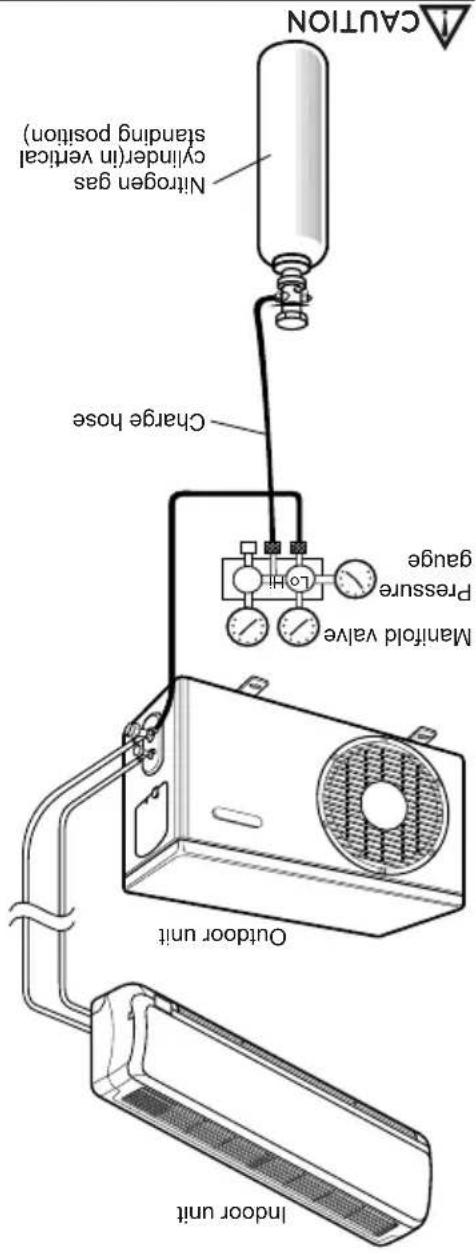
There is a risk of fire and explosion. - Inert gas (nitrogen) should be used when you check plumbing leaks, cleaning or repairs of pipes etc. If you are using combustible gases including oxygen, product may have the risk of fires and explosions.
text_image
CAUTION Nitrogen gas cylinder (in vertical standing position) Charge hose Manifold valve gauge Pressure LOHAfter the system is found to be free of leaks, relieve the nitrogen pressure by loosening the charge hose conjector at the nitrogen cylinder. When the system pressure is reduced to normal, disconnect the hose from the cylinder.
Bubbles indicate a leak. Be sure to wipe off the soap with a clean cloth.
service valves.
Do a leak test of all joints of the tubing (both indoor and outdoor) and both gas and liquid side
To avoid nitrogen entering the refrigerant system in a liquid state, the top of the cylinder must be higher than its bottom when you pressurize the system. Usually, the cylinder is used in a vertical standing position.
CAUTION

Presurize the system to maximum 250 P.S.1.G (R-22 model) or 400 P.S.1.G. (R-410A model) with dry nitrogen gas and close the cylinder valve when the gauge reading reached 250 P.S.1.G (R-22 model) or 400 P.S.1.G (R-410A model). Next, step is leak test with liquid soap.
Be sure to use a manifold value for air purging. If it is not available, use a stop value for this purpose. The 3-way value must always be kept close.
CAUTION

Connect the manifold valve (with pressure gauges) and dry nitrogen gas cylinder to this service port with charge hoses.
Leak test

stage.
Check that each tube (both liquid and gas side tubes) between the indoor and outdoor units have been properly connected and all wiring for the test run has been completed. Remove the service valve caps from both the gas and the liquid side on the outdoor unit. Note that both the liquid and the gas side service valves on the outdoor unit are kept closed at this.
Preparation

dwnd
Air purging with vacuum
Therefore, the indoor unit and tubing between the indoor and outdoor unit must be leak tested and evacuated to remove any non condensable gas and moisture from the system.
refrigeration system.
freeze and block capillary tubing. Water may lead to corrosion of parts in the
Moisture in the refrigerant circuit may Cooling (or heating) efficiency drops.
Operating current risks.
Pressure in the system rises.
below.
Air and moisture remaining in the refrigerant system have undesirable effects as indicated
Air purging
AIR PURGING
text_image
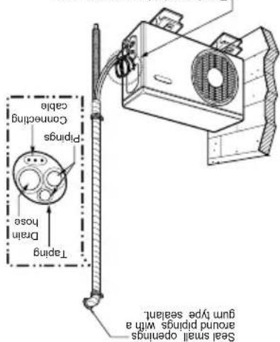
Tarp TarpSeal a small opening around the pipsigs with gum type sealant.
text_image
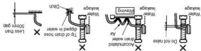
Less than 50mm gap Tip of drain hose dipped in water Acumulated drain water Air Water leakage Maying Water leakage Water leakage Do not raise■ Do not make drain piping.
equivalent.
■ Fix the piping onto the wall by saddle or
the room.
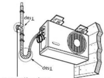
wall. Form a trap to prevent water entering
Secure the taped piping along the exterior
down to up.
- Tape the piping, and connecting cable from
the following.
installed above the indoor unit perform
In cases where the Outdoor unit is

Trap is required to prevent water from entering into electrical parts.
text_image
Seal smell openings around plirings with a gum type sealant. Tapping Drain hose Connecting cable Pliringswall using saddle or equivalent.
Secure the tapped piping along the exterior
concenting cable from down to up.
Tape the piping, drain hose and
the following.
installed below the indoor unit perform
In cases where the outdoor unit is

hose appropriate.
routed above the ground. Secure the drain
hose, the end of the drain outlet should be
If you want to connect an additional drain
kinds of vinyl tapes.
insulation material and secure IT with two
concenting portion of the indoor unit with
Form the piping by wrapping the

Form the piping
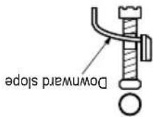
The drain hose should point downward for
easy drain flow.
C Drain piping
natural_image
Technical line drawings of two household appliances: a front-mounted air conditioner unit and a rectangular device with a handle (no text or symbols)and goes out the drain exit.
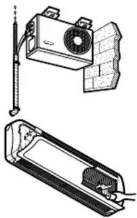
hose of the indoor unit without any leakage
Ensure the water flows through the drain
Pour a glass of water on the evaporator.
B To check the drainage.
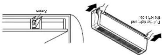
text_image
Screw Pull the right hand the left side.(1TR, 1.5TR, 2TR)
sides of the grille toward you and lift it off.
front panel. Pull the lower left and right
Remove the securing screws that retain the
the position(horizontally) by hand.
Set the air direction of lovers up-and-down to
unit cabinet.
To remove the front panel from the indoor

Checking the drainage
CHECKING THE DBALANCE AND FORMING THE PIPING
conductors.
(9) The means for disconnection from a power supply shall be incorporated in the fixed wiring and have an air gap contact separation of at least 3mm in each active (phase)
normal function of the overload.
• Vibration of a magnetic switch, which will damage the contact point, fuse breaking, disturbance of the
8) The following would be caused by voltage drop.
7) Always install an earth leakage circuit breaker in a wet or moist area.
(Particulary note the relation between cable length and thickness. (Refer to page 15))
(6) Confirm that the cable thickness is as specified in the power source specification.
on the name plate.
5) The starting voltage is maintained at more than 90 percent of the rated voltage marked
4) Confirm that electrical capability is sufficient.
3) Specification of power source.
are loose, if may cause burn-out of the wires.)
transportation. Check them and make sure that they are all tightly fastened. (If they
loose from vibrations to which the unit is subjected during the course of
2) The screw which fasten the wiring in the casing of electrical fittings are liable to come
COVER.
the method of wiring, be guided by the circuit diagram posted on the inside of control
1) Never fail to have an individual power circuit specifically for the air conditior. As for
After the confirmation of the above conditions, prepare the wiring as follows:
CAUTION
Connecting cable 2 each (Heat pump only)
Connecting Cable 1 each (Cooling only)
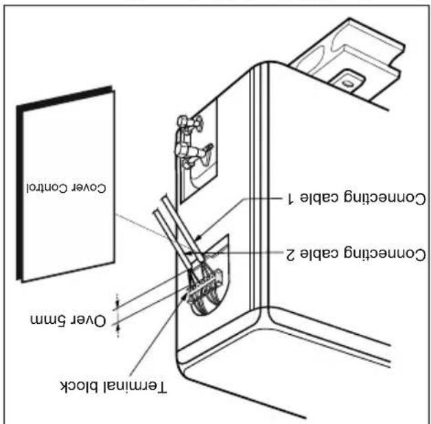
text_image
Cover Control Over 5mm Over 5mm Terminal Block Connecting cable 2 Connecting cable 1Outdoor Unit
be fitted.
adequately disconnect all supply lines must
and the unit. A disconnecting device to
25A (24K) between the power source
Use a recognized circuit breaker 20A (12K,18K),

position with the screw.
Refix the control cover to the original

the cord clamp.
Secure the cable onto the control board with

control board individually.
Connect the wires to the terminals on the
loosening the screw.
Remove the control cover from the unit by

outdoor unit
Connect the cable to the
If a power plug is not to be used, provide a circuit breaker between power source and the unit as shown below.
CAUTION
NORMAL CROSS-SECTIONAL AREA 0.75mm²
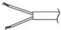
The connecting signal cable connected to the indoor and outdoor unit should be compiled with the following specifications
| Capacity (Btu/h) | NORMAL CROSS-SECTIONAL AREA |
| 9K, 12K | 1.0mm2 |
| 18K, 4.5 Star) | 1.5mm2 |
| 18K, 2.3 Star) | 2.5mm2 |
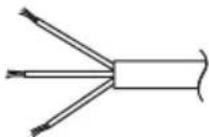
The power connecting cable connected to the indoor and outdoor unit should be compiled with the following specifications
| Capacity (Btu/h) | NORMAL CROSS-SECTIONAL AREA |
| 9K, 12K | 1.0mm2 |
| 18K | 1.5mm2 |
| 24K | 2.5mm2 |
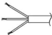
The power cord connected to the indoor unit should be complied with the following specifications
CAUTION

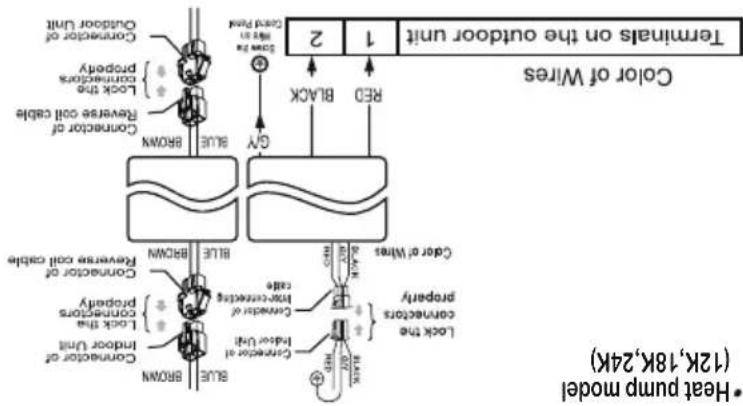
flowchart
graph TD
    A["Color of Wires"] --> B["Terminals on the outdoor unit"]
    B --> C["1"]
    B --> D["2"]
    B --> E["3D"]
    B --> F["RACK"]
    B --> G["RED"]
    B --> H["Blue"]
    B --> I["Blue"]
    B --> J["Blue"]
    B --> K["Blue"]
    B --> L["Blue"]
    B --> M["Blue"]
    B --> N["Blue"]
    B --> O["Blue"]
    B --> P["Blue"]
    B --> Q["Blue"]
    B --> R["Blue"]
    B --> S["Blue"]
    B --> T["Blue"]
    B --> U["Blue"]
    B --> V["Blue"]
    B --> W["Blue"]
    B --> X["Blue"]
    B --> Y["Blue"]
    B --> Z["Blue"]
    B --> AA["Blue"]
    B --> AB["Blue"]
    B --> AC["Blue"]
    B --> AD["Blue"]
    B --> AE["Blue"]
    B --> AF["Blue"]
    B --> AG["Blue"]
    B --> AH["Blue"]
    B --> AI["Blue"]
    B --> AJ["Blue"]
    B --> AK["Blue"]
    B --> AL["Blue"]
    B --> AM["Blue"]
    B --> AN["Blue"]
    B --> AO["Blue"]
    B --> AP["Blue"]
    B --> AQ["Blue"]
    B --> AR["Blue"]
    B --> AS["Blue"]
    B --> AT["Blue"]
    B --> AU["Blue"]
    B --> AV["Blue"]
    B --> AW["Blue"]
    B --> AX["Blue"]
    B --> AY["Blue"]
    B --> AZ["Blue"]
    B --> BA["Blue"]
    B --> BB["Blue"]
    B --> BC["Blue"]
    B --> BD["Blue"]
    B --> BE["Blue"]
    B --> BF["Blue"]
    B --> BG["Blue"]
    B --> BH["Blue"]
    B --> BI["Blue"]
    B --> BJ["Blue"]
    B --> BK["Blue"]
    B --> BL["Blue"]
    B --> BM["Blue"]
    B --> BN["Blue"]
    B --> BO["Blue"]
    B --> BP["Blue"]
    B --> BQ["Blue"]
    B --> BR["Blue"]
    B --> BS["Blue"]
    B --> BT["Blue"]
    B --> BU["Blue"]
    B --> BV["Blue"]
    B --> BW["Blue"]
    B --> BX["Blue"]
    B --> BY["Blue"]
    B --> BZ["Blue"]
    B --> CA["Blue"]
    B --> CB["Blue"]
    B --> CC["Blue"]
    B --> CD["Blue"]
    B --> CE["Blue"]
    B --> CF["Blue"]
    B --> CG["Blue"]
    B --> CH["Blue"]
    B --> CI["Blue"]
    B --> CJ["Blue"]
    B --> CK["Blue"]
    B --> CL["Blue"]
    B --> CM["Blue"]
    B --> CN["Blue"]
    B --> CO["Blue"]
    B --> CP["Blue"]
    B --> CQ["Blue"]
    B --> CR["Blue"]
    B --> CS["Blue"]
    B --> CT["Blue"]
    B --> CU["Blue"]
    B --> CV["Blue"]
    B --> CW["Blue"]
• Heat pump model (12K, 18K, 24K)
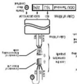
flowchart
graph TD
    A["Raw Material Input"] --> B{Material Check}
    B -->|Yes| C["Add 100%"]
    B -->|No| D["Add 100%"]
    C --> E["Output"]
    D --> F["Final Product"]
    style A fill:#f9f,stroke:#333
    style E fill:#ccf,stroke:#333
    style F fill:#ccf,stroke:#333
Cooling model (9K, 12K, 18K, 24K)
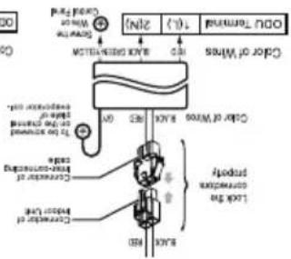
text_image
DOO TUMBER (1): 200V Water Level MUTTER AVERAGE SHEET Color of Wires Color of Water BALANCE To be seen Diameter: 5mm Distance: 5mm Temperature: 30°C Balance: 50°C BAR BAR BAR BAR BAR BAR BAR BAR BAR BAR BAR BAR BAR BAR BAR BAR BAR BAR BAR BAR BAR BAR BAR BAR BAR BAR BAR BAR BAR BAR BAR BAR BAR BAR BAR BAR BAR BAR BAR BAR BAR BAR BAR BAR BAR BAR BAR BAR BAR BAR Bar• Cooling model (9K,12K) (Optional)
as those of the indoor unit.)
outdoor unit and the terminal no. are the same
(Ensure that the color of the wires of the
Outdoor Unit connection.
housing connector (male - female housing matching).
connecting the indoor and outdoor
■ Connect the cable to the indoor unit by
indoor to outdoor unit.
Connect the cable from
text_image
Torque wrench Liquid side piping (Smaller diameter) Gas side piping (Bigger diameter) Outdoor unit| Outside diameter | Torque | ||
| mm | inch | kgf·cm | N·m |
| ∅6.35 | 1/4 | 180~250 | 17.6~24.5 |
| ∅9.52 | 3/8 | 340~420 | 33.3~41.2 |
| ∅12.7 | 1/2 | 550~660 | 53.9~64.7 |
| ∅15.88 | 5/8 | 630~820 | 61.7~80.4 |
| ∅19.05 | 3/4 | 990~1210 | 97~118.6 |
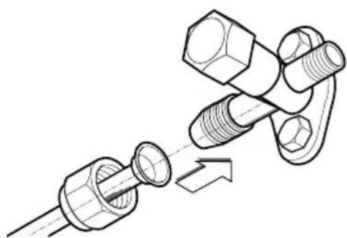
When tightening the flare nut with torque wrench, ensure the direction for tightening follows the arrow on the wrench.
B Finally, tighten the flare nut with torque wrench until the wrench clicks.
natural_image
Technical illustration of a mechanical assembly with threaded components and a pipe fitting (no text or symbols)A) Ailgin the center of the pipygs and sufficiently tighten the flare nut by hand.
Confection of the binding-Outdoor
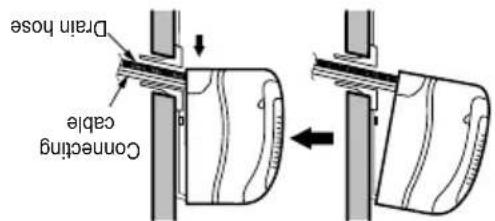
Press the lower left and right sides of the unit against stats(clicking sound).
text_image
Drain hose Connecting cableEnsure that the hooks are properly seated on the installation plate by moving it left and right.
Remove the spacer.
Indoor unit installation

text_image
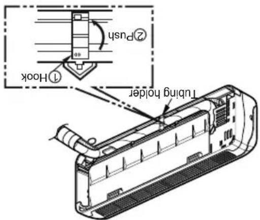
1-Hook 2-Push Tubing holderHook the edge of tubing holder to tap on chassis and push the bottom of tubing holder to be engaged at the bottom of chassis.
Set the pipsigs and the drain hose to the back of the chassis with the tubing holder.

text_image
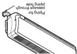
Piping for passage through pinning holeReroute the pipygs and the drain hose across the back of the chassis.

text_image
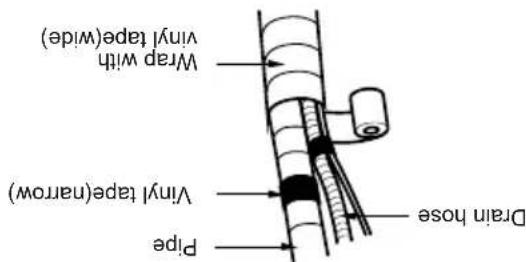
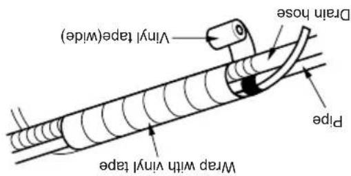
Wrap with vinyl tape(wide) Vinyl tape(narrow) Drain hose PipeBundle the piping and drain hose together by wrapping them with cloth tape over the range within which they fit into the rear piping housing
section.
FLAIRING WORK AND CONNECTION OF PILING

text_image
Conning cable Vinyl tape(narrow) Pipe Wrap with vinyl tape Vinyl tape (wide) Indoor pipe ConvectionWrap the area which accommodates the rear piping housing section with vinyl tape.
text_image
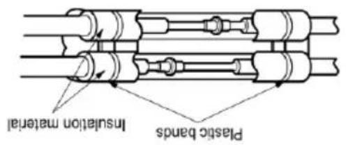
Plastic bands Insulation materialOverlap the connection pipe heat insulation and the indoor unit pipe heat insulation material. Bind them together with vinyl tape so that there is no gap.
G Wrap the insulation material around the connecting portion.
text_image
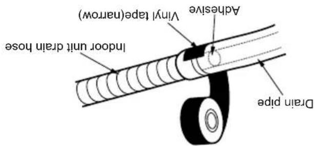
Vinyl tape(narrow) Adhesive Indoor unit drain hose Drain pipeWhen extending the drain hose at the indoor unit. Install the drain pipe.
| Outside diameter | Torque | ||
| mm | inch | kgf·cm | N·m |
| ∅6.35 | 1/4 | 180~250 | 17.6~24.5 |
| ∅9.52 | 3/8 | 340~420 | 33.3~41.2 |
| ∅12.7 | 1/2 | 550~660 | 53.9~64.7 |
| ∅15.88 | 5/8 | 630~820 | 61.7~80.4 |
| ∅19.05 | 3/4 | 990~1210 | 97~118.6 |
text_image
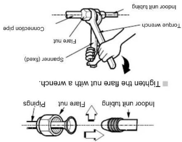
Tighten the flare nut with a wrench. Flare nut Pirpings Spanser (fixed) Canction pipe Indoor unit tubing Torque wrench Indoor unit tubing- Align the center of the pipsings and sufficiency together in their face nut by hand.
F Connecting the pips to the indoor unit and the drain hose to drain pipe.
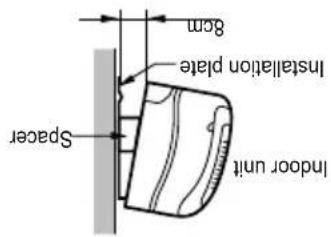
text_image
8cm Installation plate Spacer indoor unit- Hang the indoor unit from the hooks at the top of the installation plate.
- Insert the spacer etc. between the indoor unit and the installation plate and separate the bottom of the indoor unit from the wall.
E indoor unit installation
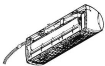
natural_image
Technical line drawing of a cylindrical device with internal structure and cable (no text or symbols)- Connecting cable
D Tape the drain hose and the connecting cable.
C ■ Insert the connecting cable into the indoor unit. ■ Don't connect the cable to the indoor unit. ■ Make a small loop with the cable for easy connection later.
FLAIRING WORK AND CONNECTION OF PILING
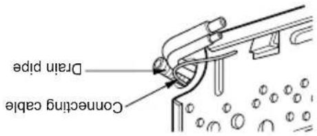
text_image
Connecting cable Drain pipeB Insert the piping, drain hose and the connecting cable into the piping hole.
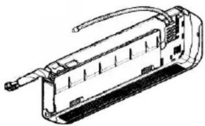
natural_image
Technical line drawing of a mechanical component with no visible text or symbolsRoute the indoor tubing and the drain hose to the required piping hole position.
For right rear piping
text_image
Drain hose Vinyl tape(wide) Pipe Wrap with vinyl tapehousing section.
Bundle the piping and drain hose together by wrapping them with vinyl tape over the range within which they fit into the rear piping
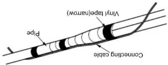
text_image
Vinyl tape(narrow) Pipe Connecting cable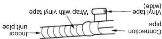
text_image
Vinyl tape (wide) Wrap with vinyl tape Indoor pipe CompressionWrap the area which accommodates the rear piping housing section with vinyl tape.
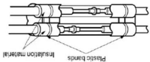
text_image
Plastic bands Insulation material■ Overlay the connection pipe insulation material and the indoor unit pipe insulation material. Bind them together with vinyl tape so that there is no gap.
F Wrap the insulation material around the connecting portion.
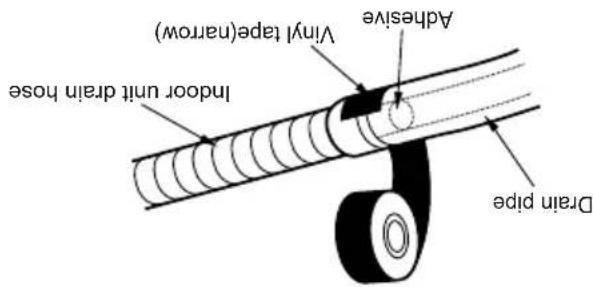
text_image
Vinyl tape(narrow) Adhesive Indoor unit drain hose Drain pipeWhen extending the drain hose at the indoor unit, install the drain pipe.
| Outside diameter | Torque | ||
| mm | inch | kgf·cm | N·m |
| ∅6.35 | 1/4 | 180~250 | 17.6~24.5 |
| ∅9.52 | 3/8 | 340~420 | 33.3~41.2 |
| ∅12.7 | 1/2 | 550~660 | 53.9~64.7 |
| ∅15.88 | 5/8 | 630~820 | 61.7~80.4 |
| ∅19.05 | 3/4 | 990~1210 | 97~118.6 |
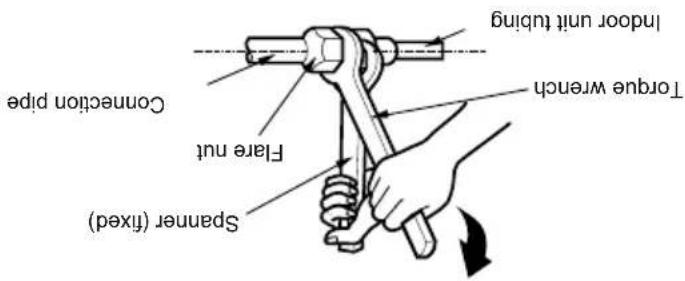
text_image
Window unit tubing Indoor unit tubing Force wrench Fire nut Connection pipe Tangible (fixed) Spanner (fixed)Tighten the flare nut with a wrench.
FLAIRING WORK AND CONNECTION OF PILING
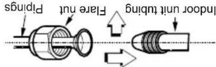
text_image
Flare nut Pirings Indoor unit tubing■ Ailgin the center of the pipsings and sufficiency tighten the flare nut by hand.
E Connecting the pips to the indoor unit and drain hose to drain pipe.
Press the lower left and right sides of the unit against the installation plate until the hooks engage into their slots (clicking-sound).
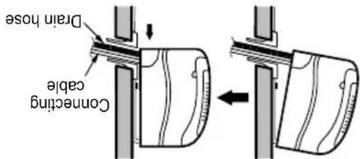
text_image
Drain hose Connecting cable■ Hook the indoor unit onto the upper portion of the installation plate. (Engage the two hooks of the rear top of the indoor unit with the upper edge of the installation plate.) Ensure that the hooks are properly seated on the installation plate by moving it left and right
D indoor unit installation
If the drain house is routed inside the room, insulate the hose with an insulation material* so that dripping from "sweating" (condensation) will not damage furniture or floors. *Foamed polyethylene or equivalent is recommended.
NOTE
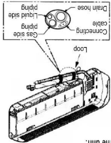
text_image
Gas side piping Liquid side piping Drain hose Connecting cable LoopTape the tubing, drain hose and the connecting cable. Be sure that the drain hose is located at the lowest side of the bundle. Locating at the upper side can cause drain pan to overflow inside the unit.
Do not connect the cable to the indoor unit. Make a small loop with the cable for easy connection later.
B Insert the connecting cable into the indoor unit from the outdoor unit through the piping hole.
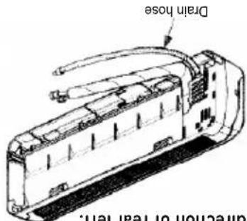
text_image
Drain hose direction of rear left.Route the indoor tubing and the drain hose in the direction of rear left.
For left rear piping
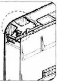
natural_image
Technical line drawing of a mechanical component or bracket (no text or symbols visible)When install, make sure that the remaining parts must be removed clearly so as not to damage the piping and drain hose, especially power cord and connecting cable.
CAUTION
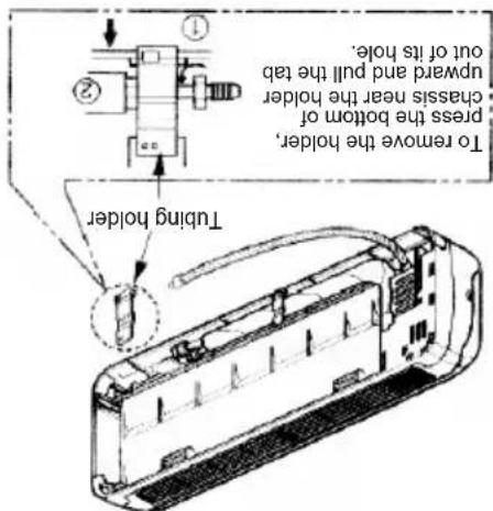
text_image
To remove the holder, press the bottom of upward and pull the tab out of its hole. chassis near the holder Tubing holder■ Repairing the indoor unit's piping and drain hose for installation through the wall. ■ Remove the plastic tubing retainer (see illustration below) and pull the tubing and drain hose away from chassis. ■ Replace the plastic tubing holder in the original position.
indoor
Connection of piping-
FLAIRING WORK AND CONNECTION OF PILING

text_image
Improper flaring = Inside is shiny without scratches. Cracked Queen thickness Surface damaged Inclosed Even length all round Smooth all round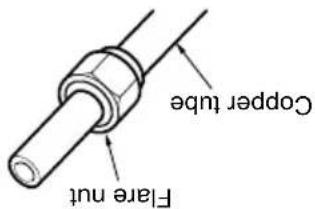
text_image
Copper tube Flare nutRemove flare nuts attached to indoor and outdoor unit, then put them on pipe/tube having completed burr removal. (not possible to put them on after faring work)
Putting nut on
text_image
Point down Reamer PipeComparison the farred work with figure below. If there is noted to be defective, cut off the farred section and do flaring work again.
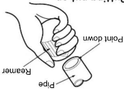
Put the end of the copper tube/pipe in a downward direction as you remove burs in order to avoid dropping burs into the tubing.
Completely remove all burs from the cut cross section of pipe/tube.
E Check
B Burns removal
text_image
Red arrow mark Clamp handle Copper pipe Yoke Coane Bar Handle A" Bar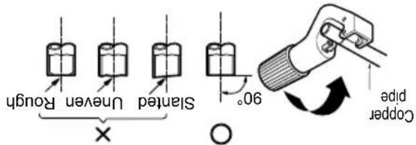
text_image
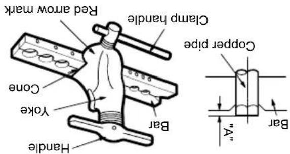
Slanted Uneven Rough 90° Copper pipeFirmly hold copper pipe in a die in the dimension shown in the table above.
| Outside diameter | A Thickness | ||
| mm | inch | mm mm | |
| 6.35 | 1/4" | 1.1 1.3 0.7 | |
| 9.52 | 3/8" | 1.5 1.7 0.8 | |
| 12.7 | 1/2" | 1.6 1.8 0.8 | |
| 15.88 | 5/8" | 1.6 1.8 | 1.0 |
| 19.05 | 3/4" | 1.9 2.1 | 1.0 |
Cut the cable 1500mm longer than the pipe length.
Measure the distance between the indoor and the outdoor unit. Cut the pipes a little longer than measured distance.
Use the piping kit accessory or the pipes purchased locally.
A Cut the pipes and the cable
Carry out flaring work using flaring tool as shown below.
Main cause for gas leakage is due to defect in flaring work. Carry out correct flaring work in the following procedure.
D Flaring work
Flaring work
FLAIRING WORK AND CONNECTION OF PILING
text_image
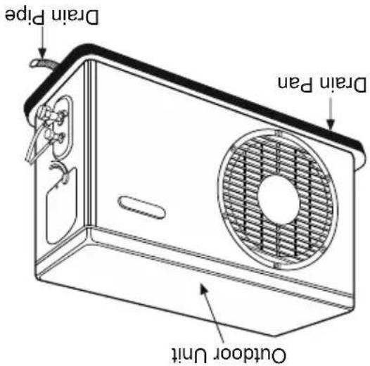
Drain Pipe Drain Pan Outdoor Unit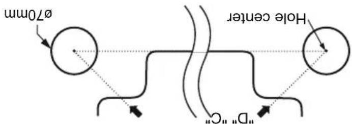
text_image
Ø70mm Hole center "D" C"Left rear piping Right rear piping
Drain pan along with drain pipe (as shown below) can be used to drain the water accumulated in the outdoor during the Heat Mode.
(Heat Pump) Usage of Drain Pan
Measure the wall and mark the centerline. It is also important to use caution concerning the location of the installation plate-routing of the wiring to power outlets is through the walls typically. Drilling the hole through the wall for piping connections must be done safely.
• Make sure that the drilled hole in the wall is property sealed (using a proper sealant, for example cement, plaster of parts etc.) after passing the installation pipe, drainage pipe and the inter- connecting cable.
CAUTION
text_image
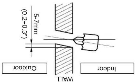
5-7mm (0.2~0.3") OUTDOOR WALL Indooroutdoor side.
Drill the piping hole with a 70mm hole core drill. Drill the piping hole at either the right or the left with the hole slightly slanted to the
text_image
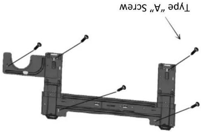
Type "A" ScrewMount the installation plate horizontally by aliguing the centriline using a level.
A Mount the installation plate on the wall with four type "A" screws. If mounting the unit on a concrete wall, use anchor bolts.
The wall you select should be strong and solid enough to prevent vibration.
How to fix installation plate Drill a hole in the wall
INSTALLATION OF INDOOR & OUTDOOR UNT
- Oil trap should be installed every 5\~7 meters. - Capacity is based on standard length and maximum allowance length is on the basis of reliability.
CAUTION
In case more than 5m
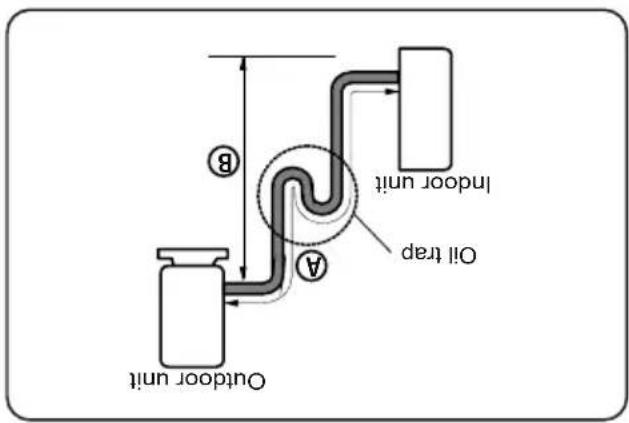
text_image
Outdoor unit A B Indoor unit Oil trap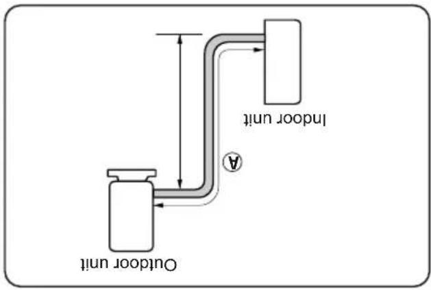
text_image
Outdoor unit Indoor unit| Capacity(Btu/h) | Pipe Size | StandardLength(m) | Max. Length(Ω(m)) | Additional Refrigerant(g/m) | |
| 6AS | LQUID | ||||
| 9K | 3/8" | 1/4" | 3 to 5 | 20 | 20 |
| 9K, 12K,18K (2,3 star)18K Heat Pump | 1/2" | 1/4" | 3 to 5 | 20 | 20 |
| 18K (5 star)24K Cooling | 5/8" | 1/4" | 3 to 5 | 20 | 30 |
| 24K Cooling & Heat Pump | 5/8" | 3/8" | 3 to 5 | 20 | 30 |
Piping length and elevation
If the outdoor unit is installed on a roof structure, be sure to level the unit. Ensure the roof structure and anchoring method are adequate for the unit location. Consult local codes regarding rooftop mounting.
Roftop installation
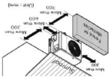
text_image
(Uvr : mm) More than 700 More than 600 More than 300 Sunroof Air ducts 4 200disturb neighbors.
Select a place so that the warm air and noise from the air conditioner do not
and vibration are minimum.
account and select a place where noise
Take the air conditiorer weight into
path of the warm air.
Do not place animals and plants in the
space.
Ensure that the space around the back and sides is more than 300mm. The front of the unit should have more than 700mm of
condenser is not restricted.
prevent direct sunlight or rain exposure, make sure that heat radiation from the
If an awning is built over the unit to
Outdoor Unit
install the indoor unit on the wall where the height from the floors more than 2300 mm.
CAUTION
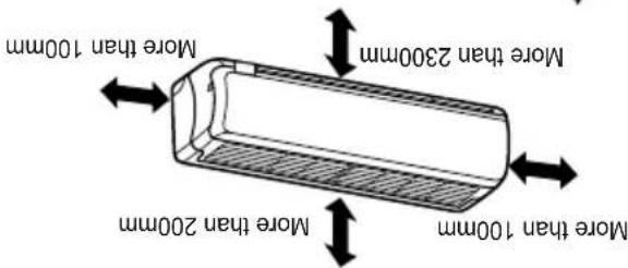
text_image
More than 100mm More than 200mm More than 2300mm More than 100mm200mm from ceiling. Use a stud finder to locate studs to prevent unnecessary damage to the wall.
Ensure that the space around the left and right of the unit is more than 100mm. The unit should be installed as high on the wall as possible, allowing a minimum of
Do not install near a doorway.
can be convenience routed away.
Make sure that condensation drainage
obstacles in front of the unit.
Select a place where there are no
unit.
Do not have any heat or steam near the
A Indoor Unit
Select the best location
Read completely, then follow step by step.
INSTALLATION OF INDOOR & OUTDOOR UNIT
| S.No. Required Tools | |
| 1 | Level Gauge |
| 2 | Screw Driver |
| 3 | Electric Drill |
| 4 | Hole Core Drill (Dia-Tomm) |
| 5 | Flaring Tool Set |
| 6 | Specified torque wrenches 1.8kg.m, 4.2kg.m, 5.5kg.m, 6.6kg.m(Different depending on model no.) |
| 7 | Spanner (Half Union) |
| 8 | Hexagonal Wrench |
| 9 | Gas-Leak Detector |
| 10 | Vacuum Pump |
| 11 | Gauge Manifold |
| 12 | Thermometer |
Installation Tools
| Name Shape Others | |
| Sleeve | |
| Bushing Sleeve | |
| Putty (Gum type sealant) | |
| Vinyl tape (Wide) | |
| Gas side piping | |
| Liquid side piping | |
| Additional drain pipe | |
| Vinyl tape | |
| Sadde | |
| • Owner's Manual • Installation Manual |
Installation parts you must purchase
| Name Quantity Shape Others | |
| Type, A. Screw | 5 |
| Installation Plate | 1 |
| Type, B. Screw | 2 |
| Holder Remote Control | 1 |
| • Owners' Manual • Installation Manual |
Installation parts provided with the unit
INSTALLATION PARTS
- Do not install the product where it will be exposed to sea wind (salt spray) directly. - It may cause corrosion on the product. Corrosion, particularly on the condenser and evaporator fins, could cause product malfunction or inefficient operation.
• Install the air conditioner where the noise from the outdoor unit or the exhaust gas will not cause inconvenience to neighbors. Failure to do so may result in conflict between neighbors. • Use two or more people to lift and transport the product. - Avoid personal injury.
• Install the drain house to ensure that water is drained away properly. - A bad connection may cause water leakage. - Keep level even when installing the product. - To avoid vibration or water leakage.
- Always check for gas (refrigerant) leakage after installation or repair of product. - Low refrigerant levels may cause failure of product or may effect product performance.
• Do not store or use flammable gas or combustibles near the product. - There is risk of fire or failure of product.
Operation
- Do not install the product on a defective installation stand. - It may cause injury, accident, or damage to the product. - Be sure the installation area does not deteriorate with age. - If the base collapses, the air conditioner could fall with it, causing property damage, product failure, and personal injury.
- Do not use a defective or underrated circuit breaker. Use this appliance on a dedicated circuit. - There is risk of fire or electric shock. - For electrical work, contact the dealer, seller, a qualified electrician, or an Authorized Service Center. - Do not disassemble or repair the product. There is risk of fire or electric shock. - Always ground the product. - There is risk of fire or electric shock. - Always install a dedicated circuit and breaker. - Install the panel and the cover of control box securely. - There is risk of fire or electric shock. - Improper wiring or installation may cause fire or electric shock. - Use the correctly rated breaker or fuse. - There is risk of fire or electric shock. - Do not modify or extend the power cable. - There is risk of fire or electric shock. - Do not let the air conditioner run for a long time when the humidity is very high and a door or a win- dow is left open. - Moisture may condense and wet or damage furniture. - Sharp edges could cause injury. Be especially careful of the case edges and the fins on the con- denser and evaporator. - For installation, always contact the dealer or an Authorized Service Center. - There is risk of fire, electric shock, explosion, or injury.
installation
• Installation or repairs made by unqualified persons can result in hazards to you and others. • The information contained in the manual is intended for use by a qualified service technician familiar with safety procedures and equipped with the proper tools and test instruments. • Failure to carefully read and follow all instructions in this manual can result in equipment mail- function, property damage, personal injury and/or death.
WARNING
It can result in minor injury or product damage when the directions are ignored.
CAUTION
It can result in serious injury or death when the directions are ignored.
WARNING
Always comply with the following precautions to avoid dangerous situations and ensure peak performance of your product
READ ALL INSTRUCTIONS BEFORE USING THE APPULANCE.
IMPORTANT SAFETY INSTRODUCTIONS
Date of purchase :
Dealer's name :
You can find them on a label on the side of each unit.
Serial number:
Model number :
Staple your receipt to this page in case you need it to prove the date of purchase or for warranty purpose. Write the model number and the serial number here:
For your records
• Avoid excessive cooling. This may be harmful for your health and may consume more electricity. • Block sunlight with blinds or curtains while you are operating the air conditioner. • Keep doors or windows closed tightly while you are operating the air conditioner. • Adjust the direction of the air flow vertically or horizontally to circulate indoor air. • Speed up the tan to cool or warm indoor air quickly, in a short period of time. • Open windows regularly for ventilation as the indoor air quality may deteriorate if the air con- • Clean the air filter once every 2 weeks. Dust and impurities collected in the air filter may block the air flow or reduce the cooling/dehumidification functions. (Reter page no. 19 and 20 details of owner's manual).
below:
Here are some tips that will help you minimize the power consumption when you use the air conditioner. You can use your air conditioner more efficiently by referring to the instructions
TIPS FOR SAVING ENERGY
21 Installation guide at the seaside
20 Test running
18 Air purging
6uidid
17 Checking the drainage and forming the
and outdoor unit
15-16 Connecting the cable between indoor
14 Convention of piping-Outdoor
12 For right rear piping
11 For left rear piping
11 Convention of piping-indoor
10 Flaring Work
10-14 Flaring Work and Connection of Piping
8-9 Installation of indoor & Outdoor Unit
8 INSTALLATION
7 installation Tools
6 installation Parts you must purchase
6 installation Parts provided with the Unit
6 INSTALLATION PARTS 9
4 IMPORTANT SAFETY INSTRUCTIONS
3 Tips FOR SAVING ENERGY
TABLE OF CONTENTS
MFL39754865
P/No. MFL39754865_V3

For Split AC Domestic Models
TYPE: WALL MOUNTED
Please read this installation manual completely before installing the product and retain it for future reference.
CONDITIONER ROOM AIR
INSTALLATION MANUAL