
LSN5PW5M - Air-conditioner LG - Free user manual and instructions
Find the device manual for free LSN5PW5M LG in PDF.


User questions about LSN5PW5M LG
0 question about this device. Answer the ones you know or ask your own.
Ask a new question about this device
Download the instructions for your Air-conditioner in PDF format for free! Find your manual LSN5PW5M - LG and take your electronic device back in hand. On this page are published all the documents necessary for the use of your device. LSN5PW5M by LG.
USER MANUAL LSN5PW5M LG
Please read this manual carefully before operating your set and retain it for future reference.
TYPE : WINDOW
TABLE OF CONTENTS
Safety precautions
Safety Precautions ....3
Operating instructions
Caution while operating Air Conditioner ....4
About the Controls on the Air Conditioner ....8
Care and Maintenance ....13
Installation Instructions
Installation Instructions....14
Troubleshooting tips
Before You Call for Service....16
10 Easy steps to find AC Tonnage .....17
FOR YOUR RECORDS
Write the model and serial numbers here:
Model #
Serial #
You can find them on a label on the side of each unit.
Dealer's Name
Date Purchased
■ Staple your receipt to this page in the event you need it to prove date of purchase or for warranty issues.

READ THIS MANUAL
Inside you will find many helpful hints on how to use and maintain your air conditioner properly. Just a little preventive care on your part can save you a great deal of time and money over the life of your air conditioner. You'll find many answers to common problems in the chart of troubleshooting tips. If you review our chart of Troubleshooting Tips first, you may not need to call for service at all.

PRECAUTION
- Contact the authorized service technician for repair or maintenance of this unit.
- Please install your air-conditioner by company authorised service franchisee / authorised service and sales dealer.
- The air conditioner is not intended for use by young children or invalids without supervision.
- Young children should be supervised to ensure that they do not play with the air conditioner.
- When the power cord is to be replaced, replacement work shall be performed by authorized personnel only, using only genuine replacement parts.
We recommend usage of voltage stabilizer with high / low voltage cut off in areas having voltage fluctuations.
| AC TONNAGE | STABILIZER KVA(3-STEP STABILIZER) |
| 1.0 | 3 |
| 1.5 | 4 |
| 2.0 | 5 |
Safety Precautions
To prevent injury to the user or other people and properly damage, the following instructions must be followed.
■ Incorrect operation due to ignoring instruction will cause harm or damage. The seriousness is classified by the following indications.

WARNING
This symbol indicates the possibility of death or serious injury.

CAUTION
This symbol indicates the possibility of injur y or damage to proper ties only.
■ Meanings of symbols used in this manual are as shown below.
| Be sure not to do. | |
| Be sure to follow the instruction. |

WARNING
■ Installation
Don't use a power cord, a plug or a loose socket which is damaged.
- Otherwise, it may cause a fire or electrical shock.

text_image
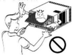
Illustration showing a person charging to a phone with a prohibition symbol, accompanied by lightning and a plug.Do not disassemble or modify products.
- It may cause failure and electric shock.
text_image
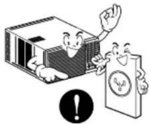
Cartoon illustration showing a person holding a device with a 'no' symbol below, indicating no violation or prohibition.Always plug into a grounded outlet.
- Otherwise, it may cause a fire or electrical shock.
natural_image
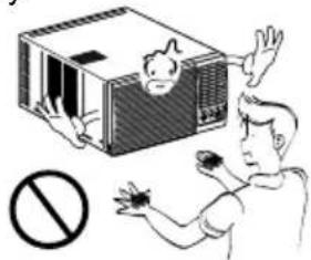
Illustration of a cartoon character interacting with a device and a document, both without readable text or symbols.Be caution when unpacking and installing.
- Sharp edges may cause injury.
natural_image
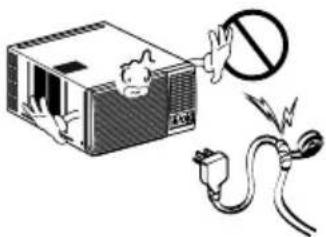
Illustration of a person reacting to a device with a prohibition symbol (no text or labels present)Do not modify or extend the power cord length.
- It will cause electric shock or fire due to heat generation.
natural_image
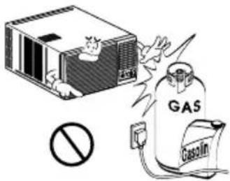
Illustration of a device with a warning symbol and electrical plug (no text or labels)Do not use the power cord near flammable gas or combustibles such as gasoline, benzene, thinner, etc.
- It may cause explosion or fire.
text_image
GAS GasolinOperation
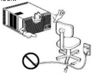
Do not place heavy object on the power cord and take care so that the cord should not be pressed.
- There is danger of fire or electric shock.
text_image
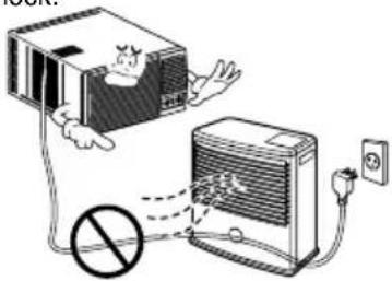
Illustration showing a cartoon character interacting with a computer monitor and an office chair, with a prohibition symbol below.Do not place the power cord near a heater.
- It may cause fire and electric shock.
text_image
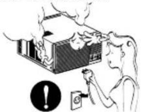
Diagram illustrating a device connection with a person inside a box and a power outlet, featuring a prohibition symbol.Unplug the unit if strange sounds, odors, or smoke come from it.
- Otherwise it may cause fire and electric shock accident.
natural_image
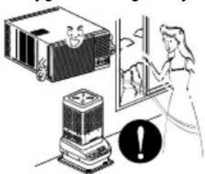
Illustration of a person using a power switch to clean a mounted device (no text or symbols present)Ventilate the room well when using this appliance together with a stove, etc.
• An oxygen shortage may occur.
natural_image
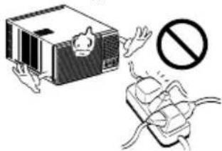
Illustration of a person using a portable air conditioner with warning symbol (no text or labels)Do not share the outlet with other appliances.
- It will cause electric shock or fire due to heat generation.
natural_image
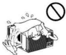
Illustration of a device with a warning symbol and a plug, no text or labels presentDo not allow water to run into electric parts.
- It will cause failure of machine or electric shock.
natural_image
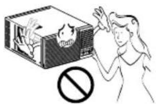
Illustration of a person standing on a box with a 'no' symbol (no text or labels)Do not open the suction inlet grill of the product during operation.
- Otherwise, it may electrical shock and failure.
text_image
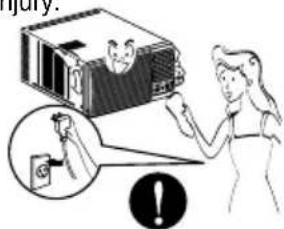
Illustration showing a person reacting to a chemical reaction with a smokestack and a prohibition symbolTurn off the power and breaker firstly when cleansing the unit.
- Since the fan rotates at high speed during operation, it may cause injury.
text_image
Injury: !Take the power plug out if necessary, holding the head of the plug and do not touch it with wet hands.
- Otherwise, it may cause a fire or electrical shock.

text_image
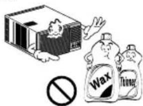
Illustration showing a person holding a device with a prohibition symbol below, indicating no smoking or disinfection.Use a soft cloth to clean. Do not use wax, thinner, or a strong detergent.
• The appearance of the air conditioner may deteriorate, change color, or develop surface flaws.
text_image
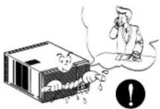
Illustration showing a box with a person, a prohibition symbol, and two labeled containers labeled 'Wax' and 'Thinner'.If water enters the product, turn off the the power switch of the main body of appliance. Contact service center after taking the power-plug out from the socket.
natural_image
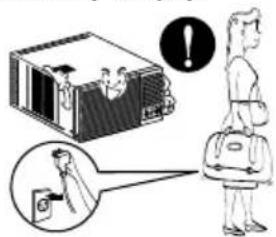
Illustration of a person reacting to a falling object inside a box, with an exclamation mark icon nearby (no text or symbols on the diagram itself)Turn off the main power switch when not using it for a long time.
- Prevent accidental startup and the possibility of injury.
text_image
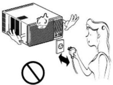
Illustration showing a person using a device to interact with a graduation cap, with an exclamation mark indicating error.Do not operate or stop the unit by inserting or pulling out the power plug.
- It will cause electric shock or fire due to heat generation.
Do not damage or use an unspecified power cord.
- It will cause electric shock or fire.
Do not operate with wet hands or in damp environment.
- It will cause electric shock.
text_image
Illustration showing a person using a device to switch an electrical outlet, with a prohibition symbol below.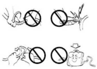
text_image
Illustration showing four different types of animals with prohibition symbols, including a snake, a plant, a mouse, and a smiling face.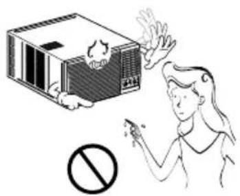
text_image
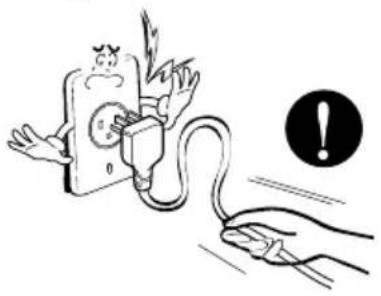
Illustration showing a person reacting to a device with a prohibition symbol, indicating no chemical reaction or toxicity.Hold the plug by the head when taking it out.
- It may cause electric shock and damage.
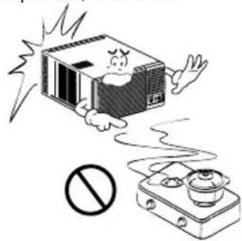
natural_image
Illustration of a hand connecting an electrical plug to a plug with a warning symbol (no text or labels)When gas leaks, open the window for ventilation before operating the unit.
• Otherwise, it may cause explosion, and a fire.
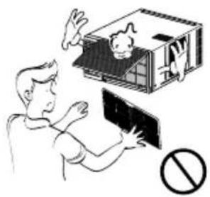
natural_image
Cartoon illustration of a person flying away from a microwave oven with a cooking pan nearby (no text or symbols)Never touch the metal parts of the unit when removing the filter.
• They are sharp and may cause injury.
natural_image
Illustration of a person interacting with a small cathouse and a monitor, with a prohibition symbol below (no text or labels)CAUTION
■ Installation
Install the product so that the noise or hot wind from the outdoor unit may not cause any damage to the neighbors.
- Otherwise, it may cause dispute with the neighbors.
natural_image
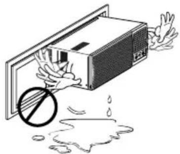
Illustration of a person opening a baby car with a prohibition symbol above (no text or labels)Keep level parallel in installing the product.
- Otherwise, it may cause vibration or water leakage.
natural_image
Illustration of a microwave oven with a hand holding it, showing liquid droplets and a prohibition symbol (no text or labels)Operation
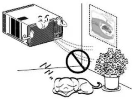
Do not put a pet or house plant where it will be exposed to direct air flow.
- It may cause injury.
natural_image
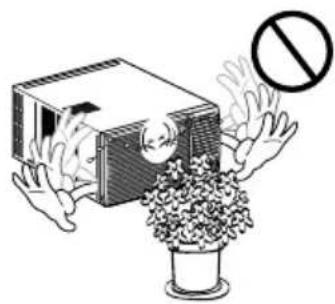
Illustration of a sleeping mouse, a sleeping box with a person, and a potted plant with a prohibition symbol (no text or labels)Do not block the inlet or outlet of air flow.
- It may cause product failure.
natural_image
Illustration of a person holding a box with a prohibition symbol (no text or symbols present)Use a soft cloth to clean. Do not use wax, thinner, or a strong detergent.
• The appearance of the air conditioner may deteriorate, change color, or develop surface flaws.
natural_image
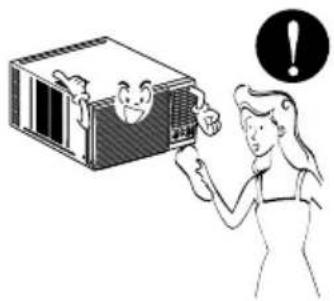
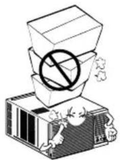
Illustration of a person interacting with a box containing a smiling face, with an exclamation mark in the background (no text or symbols on the main image)Do not step on the indoor/outdoor unit and do not put anything on it.
- It may cause an injury through dropping of the unit or falling down.
natural_image
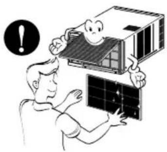
Illustration of a box with a prohibition symbol above its stack, placed on an air conditioner unit (no text or symbols present)Always insert the filter securely. Clean it every two weeks.
• Operation without filters will cause failure.
natural_image
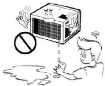
Illustration of a person assembling solar panels with a warning symbol (no text or labels)Do not drink water drained from air conditioner.
- It contains containments and will make you sick.
natural_image
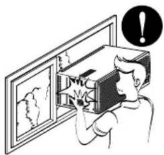
Illustration of a person reacting to a large box with a 'no' symbol, showing exhaust or pollution (no text or symbols present)Be cautious not to touch the sharp edges when installing.
- It may cause injury.
natural_image
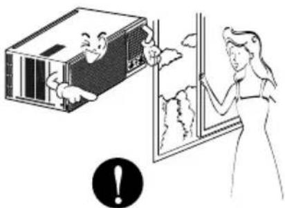
Illustration of a person opening a wall-mounted device with an exclamation mark above (no text or symbols on the device itself)Avoid excessive cooling and perform ventilation sometimes.
- Otherwise, it may do harm to your health.
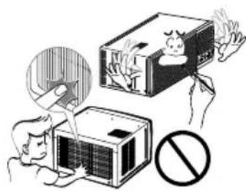
natural_image
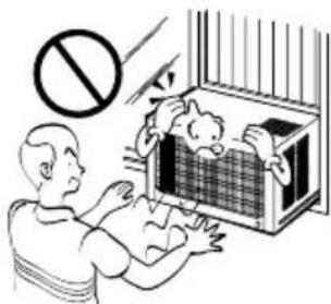
Illustration of a person opening a window with a smiling face inside, next to a box with clouds and a warning symbol (no text present)Do not insert the hands or bars through the air inlet or outlet during operation.
• Otherwise, it may cause personal injury.
natural_image
Illustration of a person using a fire extinguisher to remove a fire, with a prohibition symbol below (no text or labels)Preparing for Operation
- Contact an installation specialist for installation.
- Plug in the power plug properly.
- Use a dedicated circuit.
- Do not use an extension cord.
- Do not start/stop operation by plugging/unplugging the power cord.
- If the cord/plug is damaged, replace it with only an authorized replacement part.
Usage
- Being exposed to direct airflow for an extended period of time could be hazardous to your health. Do not expose occupants, pets, or plants to direct airflow for extended periods of time.
- Due to the possibility of oxygen deficiency, ventilate the room when used together with stoves or other heating devices.
- Do not use this air conditioner for non-specified special purposes (e.g. preserving precision devices, food, pets, plants, and art objects). Such usage could damage the items.
Cleaning and Maintenance
- Do not touch the metal parts of the unit when removing the filter. Injuries can occur when handling sharp metal edges.
- Do not use water to clean inside the air conditioner. Exposure to water can destroy the insulation, leading to possible electric shock.
- When cleaning the unit, first make sure that the power and breaker are turned off. The fan rotates at a very high speed during operation. There is a possibility of injury if the unit's power is accidentally triggered on while cleaning inner parts of the unit.
Service
For repair and maintenance, contact your authorized service dealer.
text_image
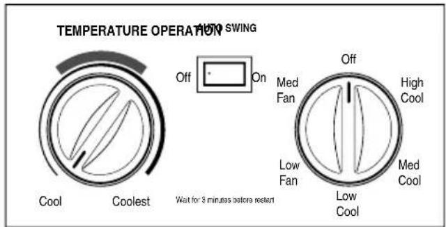
TEMPERATURE OPERATION Audi SWING Off On Cool Coolest Off Med Fan High Cool Low Fan Med Cool Low Cool Wait for 3 minutes before resetCooling Model (Fig.1)
text_image
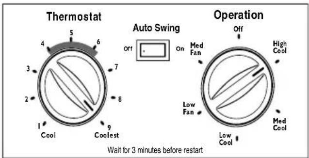
Thermostat 4 5 6 7 8 9 1 Cool Coolest Auto Swing Off On Med Fan Low Fan Operation Off High Cool Low Cool Med Cool Wait for 3 minutes before restartCooling Model (Fig.2)
OFF: Stop all operation.
FAN: Circulates filte red air.
LOW COOL: Switches on the compressor and air cooling operation at low fan speed.
MEDIUM COOL: Switches on the Compressor and air cooling operation at medium fan speed.
HIGH COOL: Switches on the compressor and air cooling operation at high fan speed.
LOW FAN: Circulates filtered at low speed.
MED FAN: Circulates filtered air at medium speed.
NOTE: If you move the switch from a cool setting to off or to a fan setting, wait at least 3 minutes before switching back to a cool setting.
■ COOLING DESCRIPTIONS
For Normal Cooling- Select High Cool or Med Cool with the OPERATION knob at the midpoint of THERMOST AT/
TEMPE RATURE knob(as mentioned in fig.1 & fig.2)
For Maximum Cool ing- Select High Cool with the OPERATION knob at
the highest number available on your Thermostat/temperature knob(position 6\~9 in fig.2)
For Quieter & Nighttime Cooling
Select Low Cool with the
OPERATION knob at the midpoint of Thermostat / Temperature knob(position 1\~4 in fig.2)
■ THERMOSTAT (TEMPERATURE)
The THERMOSTAT/TEMPERATURE is used to maintain the room temperature. The compressor will cycle on and off to keep the room at the same level of comfort.
When you turn the knob to a higher number (the right side) and the indoor air will become cooler. The temperature is selected by turning the
Thermostat/temperature knob to the desired position.
The 5 or 6 position (the middle position of arc) is a normal setting for average conditions.
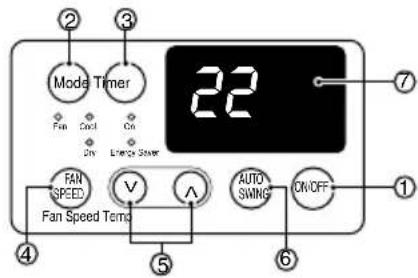
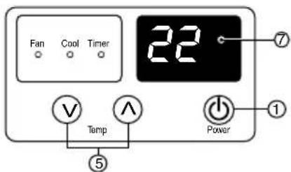
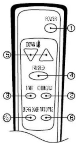
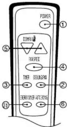
Your Panel may look like any of below mentioned panels.
Type 1
text_image
2 3 Mode Timer Fan Cool On On Lemon Starer 22 7 FAN SPEED V A AUTO SWING ON/OFF 1 Fan Speed Temp 4 5 6Type 2
text_image
Fan Cool Timer 22 7 Temp Power 1 5REMOTE CONTROLLER
text_image
POWER DOWN U FAN SPEED TIMER COOLING/FAN ENERGY S/AVER AUTO SNYINGREMOTE CONTROLLER
text_image
POWER DOWN UP FAW SPEED TIMER COOLING FAN ENERGY SVER AUTIC SONYING ① ② ③ ④ ⑤ ⑥Type 3
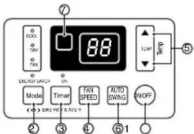
text_image
7 88 TEMP Temp ON ON Mode Timer FAN SPEED AUTO SWIKG ON/OFF (←) ENI RG S AVE R ② ③ ④ ⑥ ①Type 4
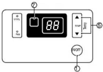
text_image
COOL FAN 88 TEMP ON/OFF ① ⑦ ⑤
text_image
Power Fan Speed s imp Mode Timer Auto Switch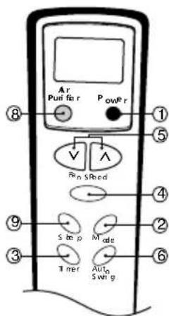
text_image
Ar Puri fi r PowFr ⑧ ① ⑤ Vin Sbed ④ ⑨ S imp Mode ② ③ Tner Auto Swi g ⑥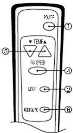
text_image
POWER TEMP FAN SPEED MODE AUTO SWITCH
Controls
Precaution: The Remote Control unit will not function properly if strong light strikes the sensor window of the air conditioner or if there are obstacles between the Remote Control unit and the air conditioner.
1 POWER BUTTON
Operation starts, when this button is pressed and stops when you press the button again.
2 OPERATION MODE SELECTION BUTTON*
Select (a)Cool (b)Energy Saver (c)Fan & (d)Dehumidification (dry) with this button. Energy saver mode-fan stops when compressor stops cooling. Approximately after 3 minutes fan will turn on to determine it cooling is needed. In dry mode, unit will run at low fan speed only with compressor 'ON'.
3 ON/OFF TIMER
Set the time of on/off operation. The timer can be set by the one hour for a maximum of 12 hours. In the first 30 minutes set temperature increases by 1^ C and in the next 30 minutes temperature increases by another 1^ C, this temperature then remains till the timer function is deactivated.
4 FAN SPEED SELECTOR
Select the fan speed in Three steps Low (F1) / Med. (F2) / High (F3) ★★
5 ROOM TEMPERATURE SETTING BUTTON
Control the room temperature within a range of 16°C to 30°C.
6 AUTO SWING
The vertical louver swings horizontally by the automatic system and stops when you press the button again.
7 SIGNAL RECEIVER
8 AIR PURIFIER (For Plasma Model)
Used to start or stop plasma purification system. Clean filter indication will be 'ON' on panel, when filter cleaning is required.
9 SLEEP BUTTON
Sleep function can be set by one hour for a maximum of 7 hours. In the first 30 minutes set temperature increases by 1^ C and in the next 30 minutes temperature increases by another 1^ C, this temperature then remains till the timer function is deactivated. This is how the sleep function behaves. The fan speed will change to low speed(F1).
★ Operation modes may vary in select models.
★★Fan speed in two steps Low (F1) / High (F2) in select models.
- AUTO RESTART
In failure of electric power the unit runs as previous setting operation when power returns.
NOTE: 'SLEEP' and 'TIMER' function cannot operate at same time.
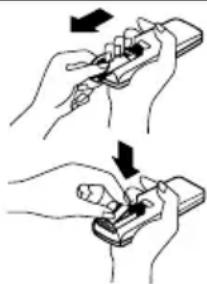
How to Insert the Batteries
1 Remove the cover from the back of the remote controller.
- Slide the cover according to the arrow direction.
2 Insert the two batteries.
- Be sure that the (+) and (-) directions are correct.
- Be sure that both batteries are new.
3 Re-attach the cover.
- Slide it back into the position.
- Do not use rechargeable batteries, such batteries differ from standard dry cells in shape, dimensions, and performance.
- Remove the batteries from the remote controller if the air conditioner is not going to be used for an extended length of time.
natural_image
Illustration of two hands holding a handheld device with arrows indicating motion (no text or symbols)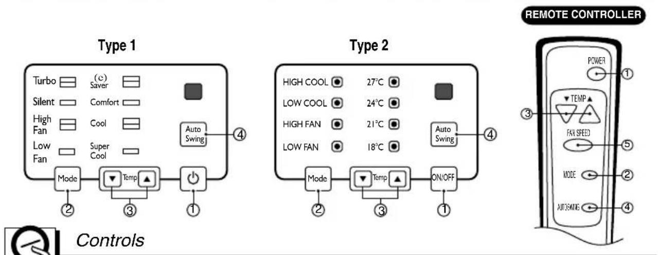
text_image
Type 1 Turbo (c) Saver Silent Comfort High Fan Cool Low Fan Super Cool Mode Temp On/OFF 4 Type 2 HIGH COOL 27°C LOW COOL 24°C HIGH FAN 21°C LOW FAN 18°C Auto Swing 4 Mode Temp ON/OFF 1 Controls REMOTE CONTROLLER POWER TEMP FAN SPEED MODE AUTOMATING 3 5 ① ② ③ ④
Precaution: The Remote Control unit will not function properly if strong light strikes the sensor window of the air conditioner or if there are obstacles between the Remote Control unit and the air conditioner.
1 POWER BUTTON
Operation starts, when this button is pressed and stops when you press the button again.
2 MODE
Select (a) Turbo (b) Silent (c) High Fan & (d) Low Fan with this button.
(a) Turbo / High Cool : Switches on compressor and air cooling operation at high fan speed.
(b) Silent / Low Cool : Switches on compressor and air cooling operation at low fan speed.
(c) High Fan : Circulates filtered air at high speed.
(d) Low Fan : Circulates filtered air at low speed.
It is recommended to select 'Silent / Low Cool' for Normal Cooling Operation and select 'Turbo / High Cool' for maximum cooling requirement.
3 TEMP
Controls Room temp. from 18^ C to 27^ C with step of 3^ C.
a) Super Cool / 18°C : 18°C Temperature Setting.
b) Cool / 21°C : 21°C Temperature Setting.
c) Comfort / 24°C : 24°C Temperature Setting.
d) (e) Saver / 27°C : 27°C Temperature Setting.
4 AUTO SWING
The vertical louver swings horizontally by the automatic system and stops when you press the button again.
5 FAN SPEED
Select fan speed in two steps - High/Low.
Additional controls and important information.
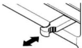
Vent Control
The vent control is located above the control knobs.
When set at CLOSE, only the air inside the room will be circulated and conditioned. When set at OPEN, some inside air is exhausted outside.
natural_image
Pure mechanical component diagram without any text, numbers, or symbolsCLOSE VENT OPEN
To open the vent, pull the lever toward you. To close it, push it in.
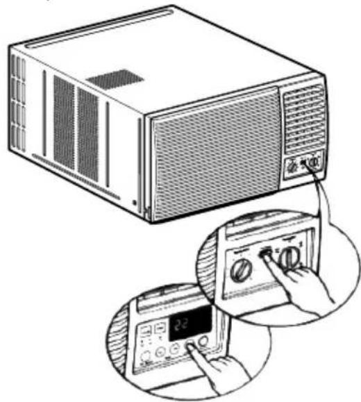
Air Direction
The direction of air can be controlled horizontally or vertically by using the horizontal louver or vertical louver.
• Horizontal Air-Direction
The horizontal air direction is adjusted by setting the AUTO SWING switch to the ON position.
• Vertical Air-Direction
Fingertip pressure on the bank of horizontal louvers adjusts the air direction up or down
natural_image
Illustration of a microwave oven connected to a digital display with a hand operating the control panel (no text or symbols present)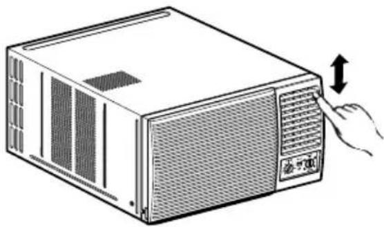
natural_image
Illustration of a computer tower with ventilation grilles and a hand inserting a button (no text or symbols)Parts Information
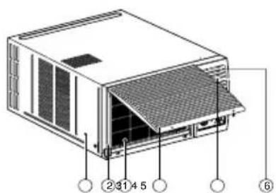
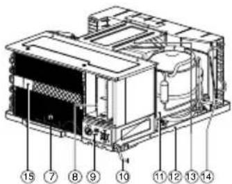
Learning parts name prior to installation will help you understanding the installation procedure.
text_image
2 3 4 5 6- CABINET
- FRONT GRILLE
- AIR FILTER
- AIR INTAKE(INLET GRILLE)
-
AIR DISCHARGE
-
VERTICAL AIR DEFLECTOR (HORIZONTAL LOUVER)
- EVAPORATOR
- HORIZONTAL AIR DEFLECTOR (VERTICAL LOUVER)
text_image
Technical diagram of an electronic device with numbered components for identification- CONTROL BOARD
- POWER CORD
- COMPRESSOR
- BASE PAN
- BRACE
- CONDENSER
- PLASMA FILTER ASSY.
Care and Maintenance
Grille and Case
Turn the air conditioner off and remove the plug from the wall outlet before cleaning.
To clean, use water and a mild detergent. Do not use bleach or abrasives.
Air Filter
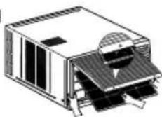
⚠ Ensure the power is off before open the front Grill. The air filter behind the front grille should be checked and cleaned at least once every 2 weeks or more often if necessary. The grille is designed to clean the filter downward.
(Fig. 1)
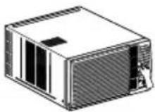
(Fig. 2)
To remove:
1 Open the inlet grille upward by pulling out the bottom of the inlet grille. (Refer Fig. 1)
2 Using the tab, pull up slightly on the filter to release it and pull it down (Fig. 1). Slide out five filter from grill (fig. 2).
3 Clean the filter with warm, soapy water below 40^ C ( 104^/F ).
4 Rinse and gently shake the water from the filter and let it dry before replacing it.
CAUTION: DO NOT operate the air conditioner without a filter because dirt and lint will clog it and reduce performance.
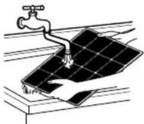
natural_image
Illustration of a water tap spraying water onto a solar panel (no text or symbols)Drainage
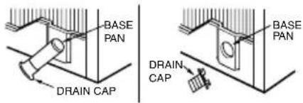
In humid weather, excess water may cause the BASE PAN to overflow. To drain the water, remove the DRAIN CAP
2 To remove the condensed water, you can install the drain pan as below.
1. Take the drain pan which is located in the air discharge.
2. Install the drain pan to the right corner of the cabinet with 4 screws.
3. Connect the drain hose to the outlet located at the bottom of the drain pan. You can purchase the drain hose or tubing locally to satisfy your particular needs. (Drain hose is not supplied).
text_image
BASE PAN DRAIN CAP DRAIN CAP BASE PAN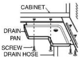
text_image
CABINET DRAIN- PAN SCREW- DRAIN HOSE(Optional)
Important
Long-off period maintenance
1) If the air conditioner is not going to be used for a long period, run the Air-conditioner with the setting in FAN Mode only and the fan speed on "HIGH" for about half an hour, to dry the whole Air-conditioner.
2) After a long off period when you are going to use the air conditioner again, repeat above point no. 1.
Caution
There will possibly be foul smell when the machine is started after a long time (1 week). This is due to various odours emitted by smoke, foodstuff, cosmetics and others, which syicks to the Air Filter and Evaporator coil. Hence, clean the Air Filter and the Evaporator before you start the machine after long time to avoid foul smell.
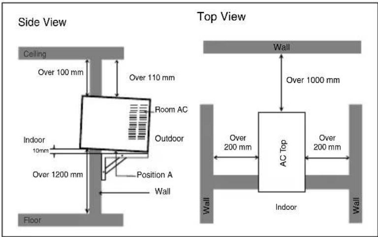
Select the Best Location
A To prevent vibration and noise, make sure the unit is installed securely and firmly.
B Install the unit where the sunlight does not shine directly on the unit.
There should be no obstacle, such as a fence or wall, within 50cm from the back of the cabinet because it will prevent heat radiation of the condenser.
Restriction of outside air will greatly reduce the cooling efficiency of the air conditioner.
D Install the unit a little obliquely outward not to leak the condensed water into the room (about 10 \~ 15mm or 1/4 bubble with level).
CAUTION: All side louvers of the cabinet must remain exposed to the outside of the structure.
text_image
Side View Ceiling Over 100 mm Over 110 mm Room AC Indoor 10mm Outdoor Over 1200 mm Position A Wall Floor Top View Wall Over 1000 mm AC Top Over 200 mm Over 200 mm Indoor Wall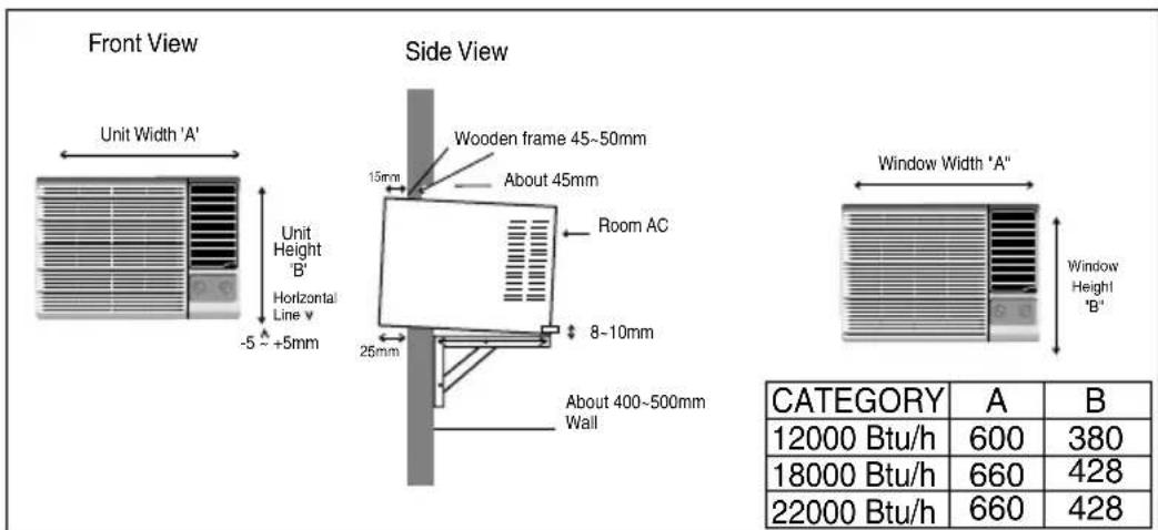
text_image
Front View Unit Width 'A' Unit Height B' Horizontal Line v -5 ~ +5mm Side View Wooden frame 45~50mm About 45mm Room AC 25mm 8~10mm About 400~500mm Wall Window Width 'A" Window Height "B" CATEGORY A B 12000 Btu/h 600 380 18000 Btu/h 660 428 22000 Btu/h 660 428Remove the Air Conditioner From the Case
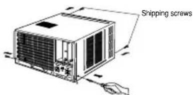
A Remove the 2 shipping screws from the back of the case.
B Remove the 2 screws on each side of the case. Keep these for later use.
text_image
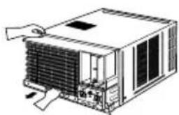
Shipping screwsC Slide the air conditioner from the case by gripping the base pan handle and pulling forward while bracing the case.
natural_image
Line drawing of a server rack unit with cooling fan and heat exchanger (no text or symbols)Install the Air Conditioner in the Case
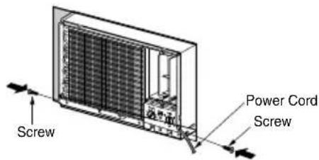
A Slide the air conditioner into the case. Reinstall the screws removed earlier on each side of the case.
text_image
Screw Power Cord ScrewCAUTION: The power cord must be connected to an independent circuit. The green wire must be grounded.
B Stuff the foam between the unit and the wall to prevent air and insects from getting into the room.
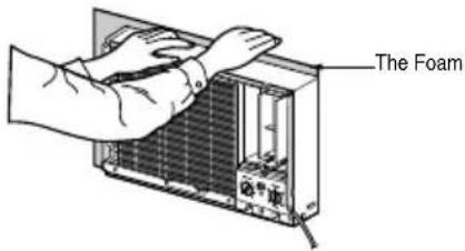
text_image
The FoamC Fix Holder lock with base pan & cabinet with screw to prevent machine from sliding out of cabinet from back grill side (Anti theft locking)
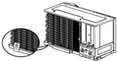
natural_image
Technical illustration of a heat exchanger unit with a close-up inset showing internal grid structure (no text or symbols)D Before installing the front grille, pull out the vent control lever located above the unit control knobs, as shown.
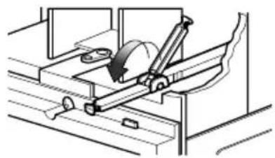
natural_image
Technical line drawing of a mechanical assembly with a rotating component (no text or symbols)E Attach the front grille to the case by inserting the tabs on the grille into the slots on the front of the case. Push the grille in until it snaps into place.
text_image
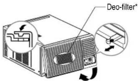
Deo-filter*When you detach the front grille from the case, push the grille to your rightside and pull it toward you.
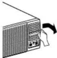
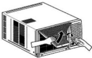
F Lift the Inlet grill and secure the front grill with a screw Lower the inlet grill into place. The maximum lift angle should not be more than 75°
natural_image
Diagram of a mechanical device with airflow arrows indicating direction (no text or symbols)Max opening angle 75 degree\*\*
* Deo-filter available in select Models. Remove Deodorizing filter carefully from the grill, shake clean it by hand & keep it in sunlight for one hour to activate it again; once it is choked.
** Grill lifting features available in selected models
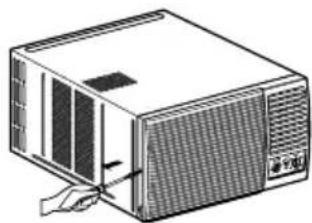
G To fix the grill with cabinet, screw it from both sides
natural_image
Illustration of a computer unit with a hand inserting a cable into the front panel (no text or symbols visible)Normal Operation
- You may hear the thermostat click when the compressor cycles on and off.
• Water will collect in the base pan during high numidity or on rainy days. The water may overflow and drip from the outdoor side of the unit.
• The fan may run even when the compressor does not. - Hissing Noise- Sound of liquid refrigerant passing through the system.
Abnormal Operation
| Problem | Possible Causes | What To Do | |
| Air conditioner does not start | ■ The air conditioner is unplugged. | Make sure the air conditioner plug is pushed completely into the outlet. | |
| ■ The fuse is blown/circuit breaker is tripped. | Check the house fuse/circuit breaker box and replace the fuse or reset the breaker. | ||
| ■ Power failure. | If power failure occurs, turn the OPERATION control to OFF( O ). When power is restored, wait 3 minutes to restart the air conditioner to prevent tripping of the compressor overload. | ||
| Air conditioner does not cool as it should | ■ Airflow is restricted. | Make sure there are no curtains, blinds, or furniture blocking the front of the air conditioner. | |
| ■ THERMOSTAT control set too warm. | Turn the THERMOSTAT knob clockwise to a cooler setting. | ||
| ■ The air filter is dirty. | Clean the filter at least every 2 weeks.See the operating instructions section. | ||
| ■ The room may have been hot. | When the air conditioner is first turned on you need to allow time for the room to cool down. | ||
| ■ Cold air is escaping. | Check for open furnace floor registers and cold air returns.Set the air conditioner's vent to the closed position. | ||
| ■ Cooling coils have iced up. | See Air Conditioner Freezing Up below. | ||
| Air conditioner freezing up | ■ Ice blocks the air flow and stops the air conditioner from cooling the room. | Set the OPERATION control at fan or HIGH cool with the THERMOSTAT at the warmer position or the temperature at more than 23°C. | |
| AC Operation is Noisy | ■ Glass pane vibrating. | Glass are to be penned | |
| ■ May be sound of condensate water. | It is normal (Generally highing only)(To avoid the noise, remove draing side knob & insert drain pipe for proper drainage) | ||
| ■ Installation levelling not not proper. | Get it levelled properly. | ||
| Unit does not Cool upon restart | ■ Compressor not starting due to 3 minute delay internally. | This is normal.If you restart the air conditioner within 3 minutes after turning it off a protective device will work to shut it off for 3 minutes. | |
10 Easy Steps to find out your AC tonnage
Dear Customer,
Please follow Below mentioned 10 easy steps to find out the AC tonnage required for your room.
| Step | Parameter | Score |
| 1 | Room Volume (Cubic feet) | |
| upto 1000 | 2 | |
| 1001 ~ 2000 | 3 | |
| 2001 ~ 3000 | 4 | |
| 3001 ~ 4000 | 5 | |
| 2 | Window Area exposed to sun (in sq. ft.) - (West facing) | |
| upto 10 | 1 | |
| 11 ~ 20 | 2 | |
| 21 ~ 30 | 3 | |
| 3 | Window Area exposed to sun (in sq. ft.) - (other directions) | |
| upto 10 | 0 | |
| 11 ~ 20 | 1 | |
| 21 ~ 35 | 2 | |
| 36 ~ 50 | 3 | |
| 4 | Wall Area exposed to sun (in sq. ft.) - (West facing) | |
| 100 | 1 | |
| 150 | 2 | |
| 200 | 3 | |
| 300 | 4 | |
| 5 | Wall Area exposed to sun (in sq. ft.) - (other directions) | |
| 100 | 0 | |
| 150 | 1 | |
| 300 | 2 | |
| 500 | 3 |
| Parameter | ScoreStep | |
| 6 | Walls area - not exposed to sun (in sq. ft.) | |
| 100 | 0 | |
| 300 | 1 | |
| 600 | 2 | |
| 1000 | 3 | |
| 7 | No. of persons occupying room | |
| 2 | 1 | |
| 4 | 2 | |
| 6 | 3 | |
| 8 | 4 | |
| 8 | Ceiling area exposed to sun (in sq. ft.) | |
| 200 | 1 | |
| 300 | 2 | |
| 400 | 3 | |
| 9 | Ceiling area if not exposed to sun (in sq. ft.) | |
| 200 | 0 | |
| 300 | 1 | |
| 400 | 2 | |
| 10 | Total Appliance Load (tube light-40w / Computer-75w, CTV - 75 etc.) | |
| 100W | 2 | |
| 250W | 3 | |
| 500W | 4 |

| Score | AC recommended |
| 6~10 | 1.0Tr |
| 11~17 | 1.5Tr |
| 18~25 | 2.0Tr |
Score Table
Example : For Room size 15 feet(L) x 12 feet(B) x 10 feet(H) with one window 4 feet x 3 feet exposed to sun (west) & one wall exposed to sun (east). The room is on First floor with ceiling not exposed to sun. The no. of persons occupying the room is 4 nos. The appliance load is - 2 tube lights, 1 Computer & 1 TV. Calculate the AC tonnage required.
As per steps given above: room volume: 15 × 12 × 10 = 1800 cu. Ft., window area = 4 × 3 = 12 sq.ft., Wall area (east) = 15 × 10 = 150
Step1 = 3
Step2 = 2
Step3 = 0
Step4 = 0
Step5 = 1
Step6 = 2
Step7 = 2
Step8 = 0
Step9 = 1
Step10= 3
Total score = 14
1.5T Window AC (From Score table)
For any further information, please contact LGEIL Branches
BRANCH BRANCH OFFICE ADDRESS PHONE NO. / FAX NO.
| Ahmedabad | LGEIL, 233-234, Platinum Plaza, Nr. Judges Bunglow Cross Road, Bodakdev, Ahmedabad-54 | 40040013-14 |
| Asansol | LGEIL, Block-E, Ist Floor, P C Chattarjee Market, Rambandhu Tala, GT Road (E) Asansol-713303 | 3292009/3292010 (Fax) 2215170 |
| Aurangabad | LGEIL, 302 CIDCO No. 3, Opp. Hotel Ramgiri, Jalna Road, Aurangabad-431003 | 5625705 / (Fax) 2474055/32095436/32095437/32095438 |
| Bangalore | LGEIL, No. 914, 2nd Floor, Shri Venkateshwara Complex, Opp. IBP Petrol Bunk, 80ft Road, 6th Block, Koramangala - Bangalore - 560095 | 41145145/41144750/41144751 |
| Bhopal | LG Electronics India Private Limited, 2nd Floor, Alankar Complex, Plot No. 10, M.P. Nagar, Zone-II, Bhopal-462011 | 4262847/4229861 (Fax) 4262848 |
| Bhubaneshwar | LGEIL, Plot No. 02,1st Flr., Bapuji Nagar, Bhubaneshwar-751009 | 2531430, 2534280 |
| Calcutta | LGEIL, 1, Ho-Chi-Min-Sarani, 6th Floor, Metro Towers, Calcutta-700071 | 22883254 (51) Fax |
| Chandigarh | LGEIL, SCO No. 142-143, 3rd Floor, Sector-34A, Chandigarh-160002 | 5087389/90 (Fax) 5089107 |
| Chennai | LGEIL, AA11, 2nd Avenue, Fatima Tower, Anna Nagar West, Chennai-600040 | 65510501~04 (Fax) 26203506 |
| Cochin | LGEIL, 40/1270, Vasudeva Buildings, T.D. Road, Ernakulam Cochin-682011 | 2369765/2369743/2370744/4027444/4027555/2360977 (Fax) |
| Coimbatore | LGEIL, 250A, Sanganur Main Road, Kannappa Nagar, Coimbatore-641027 | 2332197, 2332195 |
| Delhi | LGEIL, A-27, Mohan Co-operative, Industrial Estate, New Delhi | 26991412/11/13 (Fax) 26991410 |
| Dehradun | LGEIL, M-22, Commercial Motors Compound, Mohabewala Indl. Area, Delhi-Saharan Road, Dehradun (Uttarakhand) | 2644213/283 |
| Gurgaon | LGEIL, lInd Flr, A Block, Centre Point Bldg, Sushant Lok , Ph-l, Gurgaon-122001 | 4047461- 62 - 63/4272867, 4047460 (Fax) |
| Ghaziabad | LGEIL, J-10, RDC Rajnagar, Ghaziabad - 201001 | 9811354152/3/64/65/266 |
| Guwahati | LGEIL, Shantineer Bhawan, C K Aggarwal Path, Chenikurthi, Guwahati-781003 | 2663895/2666958/2665983/2668984 (Telefax) |
| Hyderabad | LGEIL, 1st Floor, Survey No. 54, Pulla Reddy Building, Vikarampuri, Main Road, Kharkhana, Secunderabad-500009 | 27207504, 05, 06/27204094 27201462 (Fax) |
| Hubli | LGEIL, 1 Floor, Above Bellad & Co., Near Bannigida Busstop, Gokul Road, Hubli-580030 | 4250251/52 |
| Indore | LGEIL, 3rd flr., 304 Bansi Trade Centre, 581/5 M.G. Road, Indore-452003 | 4065523~24, 4082157 (Fax) |
| Jaipur | LGEIL, B-71, Sahakar Marg, Lal Kothi Scheme, Jaipur-302015 | 5111118/5113028/5105392, 5111540 (Fax) |
| Jammu | LGEIL, Plot No. 52, Yard No. 6,Transport Nagar, Narwal, Jammu-180006 | 2477420, 2477419, 2474396, 2474384 |
| Jodhpur | LGEIL, 22(1-A)/21(2-B)/2, RIICO Heavy Industrial Area, Jodhpur-342003 | 2742384, 392 / 5120030 (Fax) |
| Karnal | LG Electronics India Pvt Ltd, Super Tyre Building, Near New Anaj Mandi, Opp. New World Restauamt, G.T. Road Karnal, Haryana | 2219201, 2219202 (Telefax) |
| Lucknow | LGEIL, B-537, Hari Kunj, Keshav Nagar, Sitapur Road, Lucknow-226020 | 2757538,39,2759121 (Fax) 2757559 |
| Ludhiana | LGEIL, Village Jhande, Near Badowal Railway Station, Opp. Ferozpur Road, Ludhiana. | 2804412 - 19 |
| Mumbai(N & S) | LGEIL, Trade Star, 4th Floor, A Wing, J.B. Nagar, Andheri Kurla Road, Andheri (E) Mumbai-400059 | 28352882-2887 / 28352889 (Fax) |
| Nagpur | LGEIL, 5A, Road No.13, Behind Msrtc Workshop, MIDC Hinga, Nagpur-440016 | 235120, 235122, Fax : 234401 |
| Patna | LGEIL, 2nd Floor, Ankit Chandra Deep Complex, Bander Bageecha, Near Samrat Hotel, Patna-800001. | 3298714, 2541845 (Fax) |
| Pune | LGEIL, 201, 2nd Floor, Plexus Complex, at 134/1, CTS No. 1337/1, Nr. Parihar Chowk, Aundh, Pune-411 007. | 020 41474100, 41474111 (Fax) |
| Rajkot | LGEIL, Sanskruti Apartment, Opp. Dr. Ambedkar Bhawan, Near Atithi Chowk, Akshar Road , Rajkot - 360004 | 2481499,2467692 (Fax) |
| Raipur | 613 to 616 , 6th Floor, Offizo, Magneto - The Mall, GE Road, Raipur - 492001 | 4053171/4037470 (Fax) 4038426/10/11 |
| Ranchi | LGEIL, 402, Commerce Tower, Opp. Gel Church Complex, Main Road, Ranchi | 3294026, 2331815 |
| Surat | LGEIL, 1001-1004, Ascon Plaza, Ilnd Flr, Anand Mahal Road, Behind Bhulka Bhavan School, Adajan, Surat-395009 | 2730982/83, 2730984 (Fax) |
| Thane | LGEIL, Gall Shop No - 206,207, 2nd Floor, Sai Plaza , Above Vijay Sales Opp. Cine Wonder Mall, Ghodbunder Road , Thane(West)-400607 | 25472633/2637 25472602(Fax) |
| Varanasi | LGEIL, Pama Complex, DLW, Lahartara Road, Shivdaspur, Manduadih, Varanasi, UP-221002 | 2373432/36/37 |
| Vijaywada | LGEIL, Door No. 32-2/1-7, Ratnamamba Street, Prajasakti Nagar, Vijaywada-520010, Andhra Pradesh | 2497283/87, (Fax) 2497284 |
| Warangal | LGEIL, House No. 1-8-598/1, First Floor, Beside HDFC Bank, Nakkalgutta, Hanamakonda-506001 (Warangal) | 2551453 |
| Kozhikode | 3/568, Thripuri Building, Wayanadu Road, First Floor,Near K.S.F.E, East Nadakkavu, Calicut-673011 | 2366755, 2366756, 2366678, (Fax) 2766678 |
LG Electronics India Pvt. Ltd.
Regd. Office: A-27, Mohan Cooperative Industrial Estate, Mathura Road, New Delhi-110044
P/No.: MFL37725109