
LSN5KR5A - Air-conditioner LG - Free user manual and instructions
Find the device manual for free LSN5KR5A LG in PDF.


User questions about LSN5KR5A LG
0 question about this device. Answer the ones you know or ask your own.
Ask a new question about this device
Download the instructions for your Air-conditioner in PDF format for free! Find your manual LSN5KR5A - LG and take your electronic device back in hand. On this page are published all the documents necessary for the use of your device. LSN5KR5A by LG.
USER MANUAL LSN5KR5A LG
Please read this manual carefully before operating your set and retain it for future reference.
TYPE : WALL MOUNTED
text_image
LG 24 x 7 CALL CENTER 1800-180-9999 5757554 CALL (Toll Free) SMS (Send SMS) www.lg.com serviceindia@lge.comLG Electronics India Pvt. Ltd.
Registered Office: Plot No. 51, Surajpur Kasna Road,
Greater Noida - 201 306 (U.P.) INDIA
Tel: 0120-2560900 Fax: 0120-2560957
TIPS FOR SAVING ENERGY
Here are some tips that will help you minimize the power consumption when you use the air conditioner. You can use your air conditioner more efficiently by referring to the instructions below:
- Do not cool excessively indoors. This may be harmful for your health and may consume more electricity. (Recommended 24^ is suitable for human body)
- Block sunlight with blinds or curtains while you are operating the air conditioner.
- Keep doors or windows closed tightly while you are operating the air conditioner.
- Adjust the direction of the air flow vertically or horizontally to circulate indoor air.
- Speed up the fan to cool or warm indoor air quickly, in a short period of time.
- Open windows regularly for ventilation as the indoor air quality may deteriorate if the air conditioner is used for many hours.
- Clean the air filter once every 2 weeks. Dust and impurities collected in the air filter may block the air flow or weaken the cooling / dehumidifying functions. (Refer page no. 20 and 21 for details)
For your records
Staple your receipt to this page in case you need it to prove the date of purchase or for warranty purposes. Write the model number and the serial number here:
Model number :
Serial number :
You can find them on a label on the side of each unit.
Dealer's name :
Date of purchase :
IMPORTANT SAFETY INSTRUCTIONS
READ ALL INSTRUCTIONS BEFORE USING THE APPLIANCE.
Always comply with the following precautions to avoid dangerous situations and ensure peak performance of your product

WARNING
It can result in serious injury or death when the directions are ignored

CAUTION
It can result in minor injury or product damage when the directions are ignored

WARNING
• Installation or repairs made by unqualified persons can result in hazards to you and others.
- The information contained in the manual is intended for use by a qualified service technician familiar with safety procedures and equipped with the proper tools and test instruments.
- Failure to carefully read and follow all instructions in this manual can result in equipment malfunction, property damage, personal injury and/or death.
Power
- Unplug the power plug immediately in the event of a blackout or thunderstorm. Failure to do so may result in fire or electric shock.
- Always use a power plug and socket with a ground terminal. Failure to do so may result in electric shock or product failure.
- Install a dedicated electric outlet and circuit breaker before you use the air conditioner. Failure to do so may result in electric shock or product failure.
- Do not connect the ground wire to a gas pipe, a lightning rod or a telephone ground wire. It may result in electric shock or product failure.
- Use a standard circuit breaker and fuse conforming with the rating of the air conditioner. Failure to do so may result in electric shock or product failure.
- Make sure to check that the power cable plug is not dirty, loose or broken and then only insert the plug completely. It may result in electric shock or product failure.
- Do not modify or extend the power cable. If the power cable or cord has scratches or skin peeled off or deteriorated then it must be replaced. It may result in fire or electric shock.
- Don't use a power cord, a plug or a loose socket which is damaged. It may result in fire or electric shock.
- Do not use a damaged power cord or plug. It may result in electric shock or product failure.
- Do not touch, operate or repair the air conditioner with wet hands. It may result in electric shock or product failure.
-
Make sure that the power plug is not damaged when you move the air conditioner. Failure to do so may result in electric shock or product failure.
-
Do not place a heater or other heating appliances near the power cable. It may result in fire, electric shock, or product failure.
- Make sure that the power cord is not pulled or damaged while the air conditioner is operating. Failure to do so may result in fire, electric shock, or product failure.
- Do not place any objects on the power cord. It may result in electric shock or product failure.
Installation
- Do not install the air conditioner on an unstable surface or where there may be a danger of it falling. It may result in death, serious injury, or product failure.
- Contact an authorized service center when you install or relocate the air conditioner. Failure to do so may result in serious injury or product failure.
- Indoor/outdoor wiring connections must be secured tightly and the cable should be routed properly so that there is no force pulling the cable from the connection terminals. Improper or loose connections can cause heat generation or fire.
- Install the panel and the cover of the control box safely. Failure to do so may result in explosion or fire.
- Do not install the air conditioner near a place with a danger of explosion or fire. It may result in explosion or fire.
- Make sure that the pipe and the power cable that connect the indoor unit and the outdoor unit are not pulled tight when you install the air conditioner. Failure to do so may result in electric shock or product failure.
- Do not mix air or gas in the system except for the specific refrigerant. If air enters the refrigerant system, it may result in an excessively high pressure that causes injury or damage to the equipment.
Use
- Be sure to use only those parts which are listed in the svc parts list. Never attempt to modify the equipment. It may result in death, serious injury, or product failure.
- Do not pull the power cord when you remove the power plug. It may result in death or electric shock.
- Discard the batteries where there is no danger of fire. Failure to do so may result in explosion or fire.
- Contact an authorized service center when the air conditioner is submerged into water due to flooding. Failure to do so may result in explosion or fire.
- Only use components that are approved by the manufacturer and do not repair or modify them. Failure to do so may result in electric shock or product failure.
- Only use the refrigerant specified on the air conditioner label. It may result in explosion or fire.
- Do not allow water to run into the air conditioner. It may result in explosion or fire.
- Do not leave flammable substances such as gasoline, benzene and thinner near the air conditioner. It may result in explosion or fire.
- Do not use the air conditioner for an extended period of time in a small place without ventilation. Ventilate the place regularly. Failure to do so may result in explosion or fire.
- Do not touch the electrostatic filter after opening the front grille. Failure to do so may result in electric shock or product failure.
- Unplug the power plug if there is a noise, smell or smoke coming from the air conditioner. Failure to do so may result in explosion or fire.
-
Make sure to ventilate sufficiently when this air conditioner and a heating appliance such as a heater are used simultaneously. Failure to do so may result in fire, serious injury, or product failure.
-
Make sure that children do not climb up the outdoor unit or impact it. Failure to do so may result in death or product failure.
- Do not turn on or off the air conditioner by plugging in or unplugging the power plug. It may result in fire or electric shock.
- When there is a gas leak, ventilate sufficiently before using the air conditioner again. Failure to do so may result in explosion or fire.
- Do not use the product for special purposes, such as preserving foods, works of art, etc. It is a consumer air conditioner, not a precision refrigeration system. It may result in death, fire or electric shock.
- Do not block the inlet or outlet of air flow. It may result in explosion or product failure.
- Do not insert hands or other objects through the air inlet or outlet while the air conditioner is operating. It may result in electric shock.
- Do not expose people, animals or plants to the cold or hot wind from the air conditioner. It may result in serious injury.
- Do not drink the water drained from the air conditioner. It may result in serious health complications.
Maintenance
- Turn the main power off and unplug the power plug when you clean or repair the air conditioner. Failure to do so may result in death, serious injury, or product failure.

CAUTION
Installation
- Do not install the air conditioner where there is direct sunlight. It may result in product failure.
- Safely dispose of packing materials such as screws, nails or batteries in a packing bag after installation or repair. It may result in serious injury.
- Do not install the air conditioner where it will be exposed to sea wind (salt spray) directly. It may result in product failure.
- Install the drain hose properly for smooth drainage of condensed water. Failure to do so may result in product failure.
• Install the air conditioner where the noise from the outdoor unit or the exhaust gas will not inconvenience the neighbors. Failure to do so may result in conflict between neighbors. - Be cautious when you unpack or install the air conditioner. Failure to do so may result in serious injury or product failure.
- Do not touch the refrigerant leakage during installation or repair. It may result in product failure.
- When transporting the equipment, there should be at least 2 or more people, or a forklift. It may result in serious injury.
Use
- Remove the batteries when the remote control is not in use for an extended period of time. Failure to do so may result in product failure.
- Make sure that the filter is installed before you operate the air conditioner. Failure to do so may result in product failure.
- Unplug the power plug when the air conditioner is not used for an extended period of time. Failure to do so may result in product failure.
- Make sure to check if there is a refrigerant leak after you install or repair the air conditioner. Failure to do so may result in product failure.
-
Do not place any objects on the air conditioner. It may result in product failure.
-
If there is a refrigerant leak during the installation of the air conditioner, ventilate the area immediately. Failure to do so may result in serious injury or product failure.
- Follow the standards of the corresponding region or country for handling the refrigerant and the air conditioner, and for disassembling the air conditioner. Failure to do so may result in product failure.
- Do not mix the batteries for the remote control with other types of batteries or mix new batteries with used batteries. Failure to do so may result in product failure.
- Do not recharge or disassemble the batteries. Failure to do so may result in explosion, fire or serious injury.
- Do not dispose of the batteries in fire. It may result in explosion or fire.
- Stop using the remote control if there is a battery fluid leak. If your cloth or skin is exposed to the battery fluid from a leak, wash it off with clean water. Failure to do so may result in serious injury.
- If you swallow the battery fluid from a leak, wash out the inside of your mouth thoroughly and then consult a doctor. Failure to do so may result in serious health complications.
- Do not let the air conditioner run for a long time when the humidity is very high or when a door or window has been left open. Failure to do so may result in product failure.
- Do not use the product for special purposes, such as preserving foods, works of art, etc. It is a consumer air conditioner, not a precision refrigeration system. There is risk of damage or loss of property.
Maintenance
- Do not use strong cleaning agents or solvents when you clean the air conditioner, or spray water. Use a smooth cloth. It may result in serious injury or product failure.
- Never touch the metal parts of the air conditioner when you remove the air filter. It may result in serious injury or product failure.
- Use a sturdy stool or ladder when you clean, maintain or repair the air conditioner at a height. Failure to do so may result in serious injury or product failure.
TABLE OF CONTENTS
2 TIPS FOR SAVING ENERGY
3 SAFETY PRECAUTIONS
8 BEFORE USE
- Prior to operation
- Components
- Electrical Safety
- Using the remote control
Inserting Batteries
➢ Installing the remote control holder
Wireless Remote Control
13 BASIC FUNCTIONS
Cooling your room
Heating your room
Removing humidity
Airing your room
Adjusting the fan speed
Adjusting the air flow direction
Setting the timer
- Setting the current time
- Turning on the air conditioner automatically at a set time
- Turning off the air conditioner automatically at a set time
- Cancelling the timer setting
Setting sleep mode
PRECAUTION
- Contact the authorized service technician for repair or maintenance of this unit.
- Please install your air-conditioner by company authorised service franchisee / authorised service and sales dealer.
- The air conditioner is not intended for use by young children or invalids without supervision.
- Young children should be supervised to ensure that they do not play with the air conditioner.
- When the power cord is to be replaced, replacement work shall be performed by authorized personnel only, using only genuine replacement parts.
16 ADVANCED FUNCTIONS
Changing room temperature quickly
Air purification mode
Indoor air purification
- Auto Clean operation
- Plasma Purification operation
Auto operation
Quiet Mode (optional)
Energy Saver mode
Dimmer
Operating the air conditioner without the remote control
21 MAINTENANCE
- Cleaning the air filter
- Cleaning the anti-allergy filter and triple filter
- Cleaning the plasma filter
23 TROUBLESHOOTING
- Self-diagnosis function
- Before requesting service
We recommend usage of voltage stabilizer with high / low voltage cut off in areas having voltage fluctuations.
| AC TONNAGE | STABILIZER KVA(3-STEP STABILIZER) |
| 1.0 | 3 |
| 1.5 | 4 |
| 2.0 | 5 |
BEFORE USE
Prior to Operation
Preparing for Operation
- Contact an installation specialist for installation.
- Plug in the power plug properly.
- Use a dedicated circuit.
- Do not use an extension cord.
- Do not start/stop operation by plugging/unplugging the power cord.
- If the cord/plug is damaged, replace it with only an authorized replacement part.
Usage
- Being exposed to direct airflow for a long time may be hazardous to your health. Do not expose occupants, pets, or plants to direct airflow for a long time.
- Due to the possibility of oxygen deficiency, ventilate the room when using the appliance together with stoves or other heating devices.
- Do not use this air conditioner for non-specified special purpose (e.g. preserving precision devices, food, pets, plants, or art objects). Such use may damage your properties. only an authorized replacement part.
Cleaning and Maintenance
- Do not touch the metal parts of the unit when removing the filter. Injury can occur.
- Do not use water to clean inside the air conditioner. Exposure to water can destroy the insulation, leading to electric shock.
- When cleaning the unit, first make sure that the power and breaker are turned off. The fan rotates at a very high speed during operation. There is a possibility of injury if the unit's power is triggered while cleaning inner parts of the unit.
Service
For repair and maintenance, contact your authorized service dealer.
Components
Symbols used in this Manual

This symbol alerts you to the risk of electric shock.

This symbol alerts you to hazards that may cause harm to the air conditioner.
Notice
This symbol indicates special notes.
Features

WARNING
This appliance should be installed in accordance with national wiring regulations. This guide acts as a guide to help to explain product features.
Indoor unit
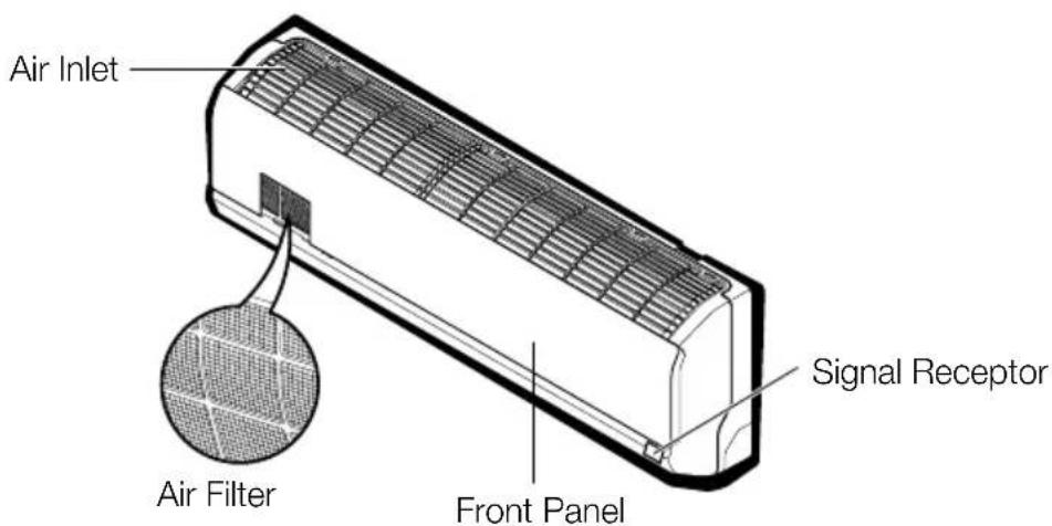
text_image
Air Inlet Signal Receptor Air Filter Front PanelOutdoor unit
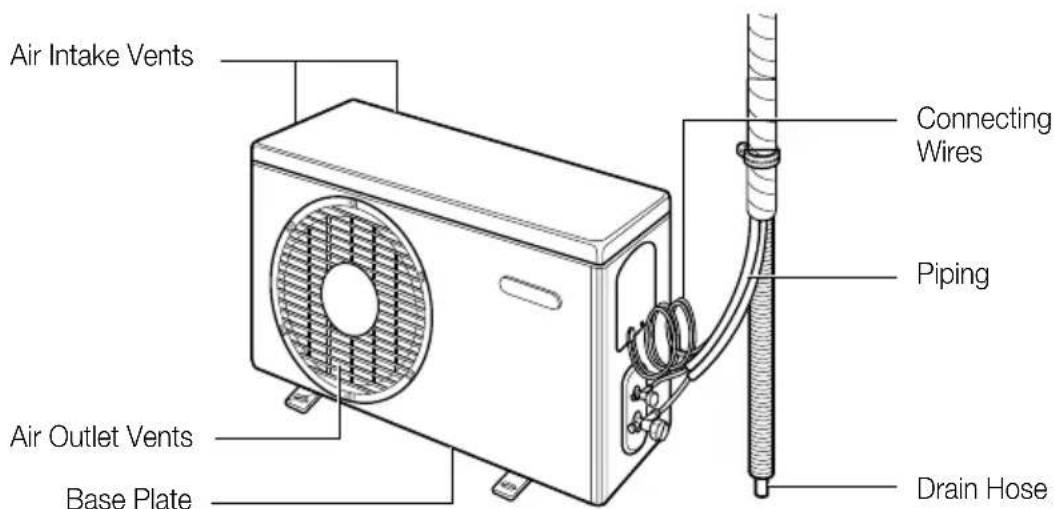
text_image
Air Intake Vents Connecting Wires Piping Air Outlet Vents Base Plate Drain HoseElectrical Safety
WARNING
• This appliance must be properly grounded.
To minimize the risk of electric shock, you must always plug into a grounded outlet.
- Do not cut or remove the grounding.
- Attaching the adapter ground terminal to the wall receptacle cover screw does not ground the appliance unless the cover screw is metal and not insulated, and the wall receptacle is grounded through the house wiring.
- If you have any doubt whether the air conditioner is properly grounded, have the wall receptacle and circuit checked by a qualified electrician.
Using the remote control
Inserting batteries
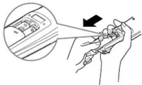
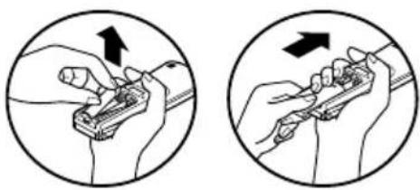
Insert batteries before using the remote control. The battery type used is AAA (1.5 V).
1 Remove the battery cover.
natural_image
Illustration of a hand holding a tool with a device, showing a zoomed-in view of the dashboard (no text or symbols present)2 Insert the new batteries and make sure that the and terminals of the batteries are installed correctly.
natural_image
Two circular diagrams showing hand tool manipulation, with arrows indicating direction (no text or symbols)3 Reattach the battery cover.

NOTE
If the display screen of the remote control starts to fade, replace the batteries.
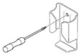
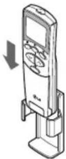
Installing the remote control holder
Install the holder where there is no direct sunlight to protect the remote control.
1 Choose a safe and easily-accessible place.
2 Remove the adhesive sticker protection film from the back of the holder before attaching it to the wall.
3 Fix the holder by fastening the 2 screws firmly with a screwdriver.
natural_image
Technical line drawing of a screwdriver inserted into a mechanical bracket (no text or symbols)4 Slide the remote control into the holder.
natural_image
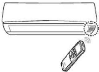
Illustration of a mobile phone with a digital display and control buttons, no text or symbols present.Operating method
Point the remote control towards the signal receiver at the bottom of the air conditioner to operate it.
natural_image
Line drawing of a car with a remote control unit emitting signal waves (no text or symbols)
NOTE
- The remote control may operate other electronic devices if pointed towards them. Make sure to point the remote control towards the signal receiver of the air conditioner.
- For proper operation, use a soft cloth to clean the signal transmitter and receiver.
Using the remote control
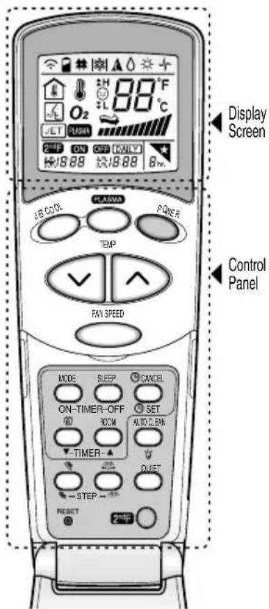
You can operate the air conditioner more conveniently with the remote control. You will find the buttons for the additional functions under the cover of the remote control.
Wireless remote control
text_image
Display Screen Control Panel ON: 88 °C O2 JET PUSAR 18.88 18.68 Bpc LECOOL PLASMA POWER TEMP FAN SPEED MODE SLEEP CANCEL ON-TIMER-OFF ROOM SET AUTO CLEAN -TIMER- QUIST -STEP - RESET 25%| DescriptionDisplay Scr | ||
| POWER | ON/OFF BUTTONTurns the power on/off. | |
| MODE | * A ◇ ☆ + | OPERATION MODE SELECTION BUTTONSelects the operation mode.Cooling operation (★) / Auto operation or Auto Changeover (▲) / Healthy Dehumidifying operation (◇) / Heating operation (★) / Air Circulation (+). |
| TEMP | 88° | ROOM TEMPERATURE SETTING BUTTONSUsed to select the room temperature. |
| FAN SPEED |  | INDOOR FAN SPEED SELECTION BUTTONUsed to select fan speed in four stops - Low,Medium, High and natural wind. |
 | HORIZONTAL VANE CONTROL BUTTONUsed to set the desired vertical airflow direction. | |
 | VERTICAL LOUVER CONTROL BUTTONUsed to set the desired horizontal airflow direction. | |
| AUTO CLEAN |  | AUTO CLEAN BUTTONUsed to set auto clean. |
| ROOM |  | ROOM TEMPERATURE CHECKING BUTTONUsed to check the room temperature. |
| ON-TIMER-OFF |  | ON/OFF TIMER BUTTONSUsed to set the time of starting and stopping operation. |
| ▼-TIMER-▲ | TIME SETTING BUTTONSUsed to adjust the time. | |
 | TIMER SET/CANCEL BUTTONUsed to set and to cancel the timer operation. | |
| RESET | RESET BUTTONUsed prior to resetting time. | |
 |  | PLASMA BUTTON (Optional)Used to start or stops the plasma-purification. |
 | DIMMER (Optional)Used to operate Dimmer Function using 2°F. | |
| SLEEP |  | SLEEP MODE AUTO BUTTONUsed to set sleep mode auto operation. |
| JET COOL | [8K02] | JET COOL BUTTONUsed to start or stop the speed cooling. The Jet Cooloperates fan in super high speed in cooling mode. |
| [2HS2] |  | 2°F BUTTONUsed prior to using modes printed in blue at thebottom of buttons. |
| [WWEW] |  | ENERGY SAVER MODEUsed to operate Energy Saver function. |
| QUIET | QUIET MODE (Optional)Used to operate Quiet Mode function. |
BASIC FUNCTIONS
Cooling your room
(Cooling operation)
1 Press POWER to turn on the power.
2 Open the remote control cover.
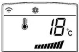
3 Press ○ repeatedly to select the cooling operation.
- Following is the display on the display screen.
text_image
18℃4 Press ☑ or △ to set the desired temperature.
- The temperature range is 18°C - 30°C.
Heating your room
(Heating operation / Heat Pump model only)
1 Press POWER to turn on the power.
2 Open the remote control cover.
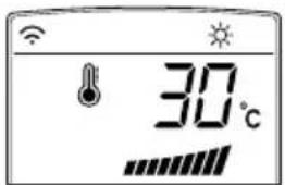
3 Press ☐ repeatedly to select the heating operation.
- Following is the display on the display screen.
text_image
30°C4 Press √ or ▶ to set the desired temperature.
- The temperature range is 18°C - 30°C.
NOTE
Cooling-only models do not support this function.
Removing humidity (Dehumidification operation)
This mode removes excess moisture from an environment with high humidity or in the rainy season, in order to prevent mold from setting in. This mode adjusts the room temperature and the fan speed automatically to maintain the optimal level of humidity.
1 Press POWER to turn on the power.
2 Open the remote control cover.
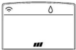
3 Press ○ repeatedly to select the dehumidifying operation.
- ⬇ is displayed on the display screen.
natural_image
Simple line drawing of a refrigerator with icons for Wi-Fi, water drop, and battery (no text or symbols)NOTE
- In this mode you cannot adjust the room temperature, as it is adjusted automatically. Also, the room temperature is not displayed on the display screen.
- In this mode indoor unit fan and outdoor unit will be OFF when set temperature is achieved.
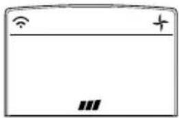
Airing your room (Air Circulation operation)
This mode only circulates the indoor air without changing the room temperature. The cooling lamp lights up in air circulation mode.
1 Press POWER to turn on the power.
2 Open the remote control cover.
3 Press ○ repeatedly to select the air circulation operation.
- Following will be displayed on the display screen.
natural_image
Simple line drawing of a rectangular device with Wi-Fi and plus/minus symbols (no text or labels)4 Press FAN SPEED to adjust the fan speed.
Adjusting the fan speed
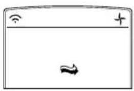
1 Press FAN SPEED repeatedly to adjust the fan speed.
2 Select ⇌ if you want natural air.
The fan speed adjusts automatically.
text_image
Diagram showing Wi-Fi signal, a plus sign, and a double-headed arrow symbol inside a rectangular boxNatural wind (CHAOS Logic)
For fresher feeling, press the INDOOR FAN SPEED SELECTION BUTTON and set to Natural wind mode.
In this mode, the wind blows like a natural breeze by automatically changing fan speed.
Adjusting the air flow direction
Selectable Air Swing (Horizontal) (Optional)
1 To adjust the direction of the air flow horizontally.
2 Open the remote control cover while the air conditioner is in operation.
3 Press the 2ndF Button.
4 Press the HORIZONTAL VANE CONTROL BUTTON.
Each time the button is pressed, the air flow direction is changed in the direction of the arrow.

Automatic Air Swing (Horizontal)
To adjust the direction of the air flow automatically, switch OFF 2ndF button and press 🔒 button.
Selectable Air Swing (Vertical) (Optional)
1 To adjust the direction of the air flow vertically.
2 Open the remote control cover while the air conditioner is in operation.
3 Press the 2ndF Button.
4 Press the VERTICAL LOUVERS CONTROL BUTTON.
Each time the button is pressed, the air flow direction is changed in the direction of the arrow.

Automatic Air Swing (Vertical)
To adjust the direction of the air flow automatically, switch OFF 2ndF button and press 📄 button.
Setting the timer
You can use the timer function to save energy and to use the air conditioner more efficiently.
Setting the current time
1 Open the remote control cover.
2 Press the RESET BUTTON.
3 Press 2ndF button and check if icon is on.
4 Press the ○ ○ until the desired time is set.
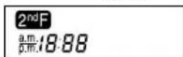
5 Press the TIMER SET/CANCEL BUTTON.
NOTE Check the indicator for a.m. and p.m.
Turning on the air conditioner automatically at a set time
1 Open the remote control cover.
2 Press 2 F button and check if icon is on.
3 Press ON-TIMER to set the desired ON time.
- The icon below is displayed on the display screen.
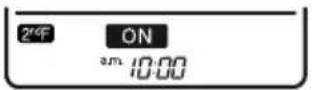
4 Press ○ ○ until the desired time is set.
5 Press TIMER SET/CANCEL BUTTON to finish.
Turning off the air conditioner automatically at a set time
1 Open the remote control cover.
2 Press 2 F button and check if icon is on.
3 Press ○ to set the desired OFF time.
- The icon below is displayed on the display screen.
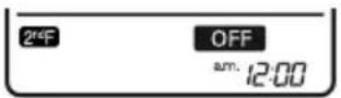
4 Press ○ ○ until the desired time is set.
5 Press TIMER SET/CANCEL BUTTON to finish.
NOTE
• This function may not be supported, depending on the model.
- This mode does not have auto restart feature.
Canceling the timer setting
1 Open the remote control cover.
2 Check if 2 ^4 icon is off.
3 Press the TIMER SET/CANCEL BUTTON aiming the remote controller at the signal receiver.
(The timer lamp on the air conditioner and the display will go off.)
Setting sleep mode
Use the sleep mode to turn off the air conditioner automatically when you go to sleep. The fan speed is set to low in sleep mode.
1 Press POWER to turn on the power.
2 Press ○ repeatedly to select the desired mode.
3 Press ○ repeatedly to select the desired number of hours (up to 7 hours).
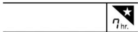
text_image
7hr.NOTE
- The sleep mode will operat e indoor fan at super low spee d in coo ling mode and at low spee d in heating mode for pleasan t sleep
In cooling mod e or he alt hy dehumidifi cation mode
The setting temperature will rise automaticly two times by 1°C over next con secuti ve 30 minutes (Maxi mum 2°C) for a com fort abl e sleep.
This will be the final setting temperature as long as sleep mode is functioning. After completion of set time until switch OFF automaticly.
ADVANCED FUNCTIONS
The air conditioner offers some additional advanced functions.
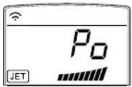
Changing room temperature quickly (Jet Cool)
This mode allows you to cool indoor air quickly in summer or warm it quickly in winter.
1 Press POWER to turn on the power.
2 Open the remote control cover.
3 Press
text_image
Po JET- In jet cooling mode, strong air blows out at a temperature of 18^ C for 30 minutes.
- In jet heating mode, strong air blows out at a temperature of 30^ C for 30 minutes.
NOTE
- In Air Circulation, Auto, or Auto Changeover mode, this function cannot be used.
- This function may not be supported, depending on the model.
Air Purification Mode (Optional)
LG Air conditioner come with a variety of filters like Anti-Bacteria filter, Tripple Filter, Virus & Allergy safe filter, Plasma Filter, which enable you to use it as a Built-in Air purifier (Even when you are not using it for cooling, hence minimal electricity consumption).
1 Press " O " Key. The unit will turn ON, with only the fan operated and Built-in Air purifier function is activated.
- PLASMA is displayed on the display screen.
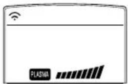
text_image
PLASMANOTE
• In this mode the compressor will not operate, hence saves electricity.
• This function may not be supported, depending on the model.
Indoor air purification
Auto Clean operation
In the cooling and dehumidifying operations, moisture is generated inside the indoor unit. Use the auto cleaning function to remove such moisture.
1 Press POWER to turn on the power.
2 Open the remote control cover.
3 Press AUTOCLEAN
- is displayed on the display screen.

text_image
18°C- If you turn off the power, the fan operates for 30 minutes and cleans the inside of the indoor unit.
NOTE
Some buttons cannot be used while the auto cleaning function is in operation.
NOTE
During Auto Clean function, "Co" will be displayed and & e-Saver icon will blink on the unit.
Plasma Purification operation (Optional)
The plasma filter removes microscopic contaminants from the intake air completely to supply clean and fresh air.
1 Press POWER to turn on the power.
2 Press
- PLASMA is displayed on the display screen.
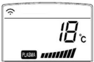
text_image
18°C PLASMANOTE
- You can use this function by pressing without turning the air conditioner on.
- Both the plasma lamp and the power lamp light up while plasma purification is in operation.
- This function may not be supported, depending on the model.
Auto operation (Artificial intelligence)
Cooling-only models
In this mode, the fan speed and the temperature adjust automatically, based on the room temperature.
1 Press POWER to turn on the power.
2 Open the remote control cover.
3 Press ○ repeatedly to select auto operation.
4 Press √ to select the desired operation code if the temperature is higher or lower than the desired temperature.
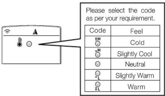
text_image
Please select the code as per your requirement. Code Feel 😊 Cold 😊 Slightly Cool 😊 Neutral 😊 Slightly Warm 😊 WarmNOTE
- In this mode, you cannot adjust the fan speed, but you can set the air deflector to rotate automatically.
- This function may not be supported, depending on the model.
Quiet Mode Operation (Optional)
This mode minimizes the fan speed of the system hence making the environment more comfortable and silent.
- Press POWER to turn on the power.
- Open the remote control cover.
- Press QUIET mode button.
Quiet Mode Feature :
In quiet mode unit display shows SL.

NOTE
This mode has Auto Restart feature. This means if during this mode, power goes OFF then unit will restart with the same mode (Quiet mode) when power comes ON.

NOTE
Quiet mode will be cancelled by pressing quiet mode key again.
e-Saver Mode
This mode minimizes power consumption during cooling and increases the set temperature to the optimal level for a more comfortable environment.
1 Press POWER to turn on the power.
2 Open the remote control cover.
3 Press ○ repeatedly to select the cooling operation.
4 Press e.
- Following is displayed on the display screen.
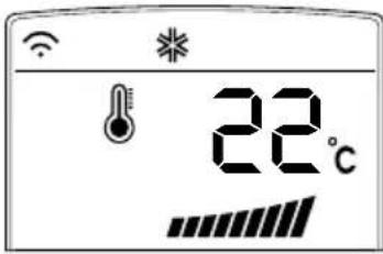
text_image
22°C
NOTE
In this mode temperature may increase after some time but only upto 26^ C.

NOTE
- This function may not be supported, depending on the model.
- This mode does not have auto restart feature.
Dimmer (Optional)
In Dimmer Mode Unit Display will be turned OFF completely but system will be in running state.
- Make sure that remote & Air conditioner are ON.
- Press 2 ^n F button.
- Press Dimmer Key to activate/deactivate dimmer function.

NOTE
Dimmer Mode will be cancelled if any key except 2 ^th F Key and Room Key is pressed (Power Key will turn OFF the Unit.

NOTE
This mode has Auto Restart feature.
Operating the air conditioner without the remote control (Forced Operation)
You can use the On/Off button of the indoor unit to operate the air conditioner when the remote control is unavailable. However, the fan speed is set to high.
1 Open the front cover.
- Lift up both sides of the cover slightly.
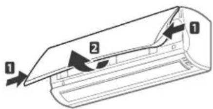
text_image
Diagram of a airflow or ventilation system with labeled components 1 and 2, showing directional arrows indicating flow direction.2 Press the On/Off button.
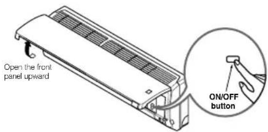
text_image
Open the front panel upward ON/OFF button- For cooling and heating models, the operation mode changes, depending on the room temperature.
| Cooling Model | Heat pump Model | |||
| Room Temp. ≥ 24°C | 21°C ≥ Room Temp. < 24°C | Room Temp. < 21°C | ||
| Operating mode | Cooling Cooling | Healthy Dehumidification Heating | ||
| Indoor FAN Speed | High High High High | |||
| Setting Temperature | 22°C 22°C | 23°C 24°C | ||
If you want to stop the unit, re-press the power button.
MAINTENANCE
Clean the product regularly to maintain optimal performance and to prevent possible breakdown.
* This may not be provided, depending on the model.
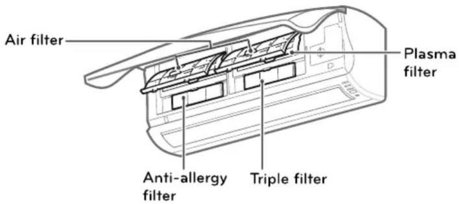
text_image
Air filter Plasma filter Anti-allergy filter Triple filter| Item | Cleaning interval | Cleaning method |
| Air filter | 2 weeks | See “Cleaning air filter.” |
| Anti-allergy filter / Triple filter | 3 months | See “Cleaning anti-allergy filter and triple Filter.” |
| Plasma filter* | 3 months | See “Cleaning the plasma filter.” |
| Indoor unit surface | Regularly | Use a soft, dry cloth. Do not use bleach or abrasives. |
| Outdoor unit | Regularly | Use steam to clean the heat exchanger coils and the panel vents (consult with technician). |

CAUTION
- Turn off the power and unplug the power cord before you perform any maintenance; otherwise it may cause electric shock.
- Never use water that is hotter than (40°C) when you clean the filters. It may cause deformation or discoloration.
- Never use volatile substances when you clean the filters. They may damage the surface of the product.

NOTE
- The location and shape of the filters may differ, depending on the model.
- Make sure to clean the heat exchanger coils of the outdoor unit regularly, as dirt collected in the coils may decrease the operational efficiency or increase energy costs.
Cleaning the air filter
Clean the air filter once every 2 weeks or more if necessary.
1 Turn off the power and unplug the power cord.
2 Open the front cover.
- Lift up both sides of the cover slightly.
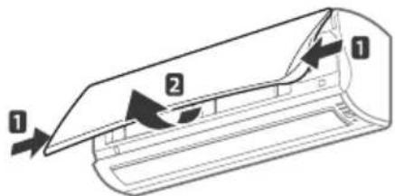
text_image
Diagram of a car air duct with labeled parts and directional arrows indicating flow or movement3 Hold the knob of the air filter, lift it up slightly and remove it from the unit.
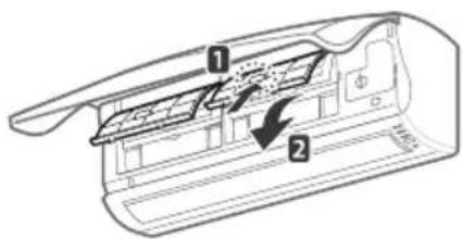
text_image
Technical diagram of a mechanical component with numbered parts and directional arrows indicating flow or movement.4 Clean the filter with a vacuum cleaner or with warm water.
- If dirt is difficult to remove, wash the filter in lukewarm water with detergent.
5 Dry the filter in the shade.
Cleaning the anti-allergy filter and triple filter
1 Turn off the power and unplug the power cord.
2 Open the front cover and remove the air filter (see "Cleaning air filter").
Outdoor Unit
The heat exchanger coils and panel vents of the outdoor unit should be checked regularly. If clogged with dirt or soot, the heat exchanger and panel vents may be professionally steam cleaned.
NOTICE
Dirty or clogged coils will reduce the operating efficiency of the system and cause higher operating costs.
3 Pull out the anti-allergy filter and the triple filter.
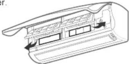
natural_image
Technical line drawing of a mechanical component with internal structure and mounting holes (no text or symbols)4 Dry the filter in direct sunlight for 2 hours.
NOTE
The location and shape of the filters may differ, depending on the model.
Cleaning the plasma filter
1 Turn off the power and unplug the power cord.
2 Open the front cover and remove the air filter (see "Cleaning air filter").
3 Remove the plasma filter in 10 seconds.
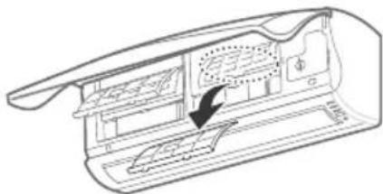
natural_image
Technical line drawing of a mechanical component with internal structure and directional arrow (no text or symbols)4 Use a vacuum cleaner to remove any dirt. - If dirt is difficult to remove, wash the filter with lukewarm water.
5 Dry the filter in the shade.
NOTE
- The location of the filters may differ, depending on the model.
- The plasma filter may not be included in some models.
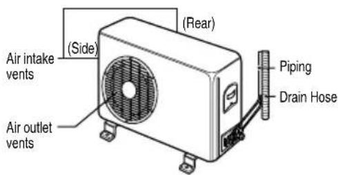
text_image
Air intake vents (Side) (Air outlet vents) (Rear) Piping Drain Hose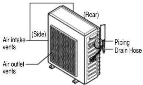
text_image
Air intake vents (Side) Air outlet vents (Rear) Piping Drain Hose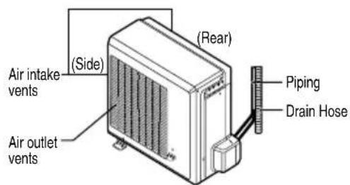
text_image
Air intake vents (Side) Air outlet vents (Rear) Piping Drain HoseTROUBLESHOOTING
Self-diagnosis function
This product has a built-in self-diagnosis function. If an error occurs, the lamp of the indoor unit will blink in 2 second intervals. If this occurs, contact your local dealer or service center.
Before requesting service
Please check the following before you contact the service center. If the problem persists, contact your local service center.
| Problem | Possible causes | Corrective action |
| There is a burning smell and a strange sound coming from the unit. | - | Turn off the air conditioner, unplug the power cord and contact the service center. |
| Water leaks from the indoor unit even when the humidity level is low. | ||
| The power cord is damaged or generating excessive heat. | ||
| A switch, a circuit breaker (safety, ground) or a fuse is not operated properly. | ||
| The air conditioner does not work. | The air conditioner is unplugged. | Check whether the power cord is plugged into the outlet. |
| A fuse is blown or the power supply is blocked. | Replace the fuse or check if the circuit breaker has tripped. | |
| A power failure has occurred. | Turn off the air conditioner when a power failure occurs. When the power is restored, wait 3 minutes, and then turn on the air conditioner. | |
| The voltage is too high or too low. | Check if the circuit breaker has tripped. | |
| The air conditioner turned off automatically at a preset time. | Press the power button again. | |
| The air conditioner does not generate cool air. | Air is not circulating properly. | Make sure that there are no curtains, blinds or furniture blocking the front of the air conditioner. |
| The air filter is dirty. | Clean the air filter once every 2 weeks. See "Cleaning Air Filter" for more information. | |
| The room temperature is too high. | In summer, it may take some time to cool indoor air. In this case, select the jet cool operation to cool indoor air quickly. | |
| Cold air is escaping from the room. | Make sure that no cold air is escaping through ventilation points in the room. | |
| The desired temperature is higher than the set temperature. | Set the desired temperature to a level lower than the current temperature. | |
| There is a heating source nearby. | Avoid using a heat generator such as an electric oven or a gas burner while the air conditioner is in operation. | |
| Air circulation operation is selected. | In the air circulation operation, air blows from the air conditioner without cooling or heating the indoor air. Switch the operation mode to the cooling operation. | |
| It is not possible to adjust the fan speed. | The auto operation, jet operation or dehumidifying operation is selected. | In some operation modes, such as the jet or dehumidifying operation modes, you cannot adjust the fan speed. Select an operation mode in which you can adjust the fan speed. |
| It is not possible to adjust the temperature. | The air circulation operation or jet operation is selected. | In some operation modes, such as the air circulation or jet operation mode, you cannot adjust the temperature. Select an operation mode in which you can adjust the temperature. |
When the air conditioner is not going to be used for a long time.
When air conditioner is not going to be used for a long time.

Operate the air conditioner on Air circulation mode (Refer to page 23) for 2 to 3 hours.
• This will dry out the internal mechanisms.

Turn off the circuit breaker, and disconnect the plug.

CAUTION
Turn off the circuit breaker when the air conditioner is not going to be used for a long time.
Dirt may collect and may cause a fire.

Remove the batteries from the remote control.
When the air conditioner is to be used again.

Clean the air filter and install it in the indoor unit.
(Refer to page 26 for cleaning filters.)

Check that the air inlet and outlet of the indoor/outdoor unit are not blocked.
BRANCH BRANCH OFFICE ADDRESS PHONE NO. / FAX NO.
| Ahmedabad | LGEIL, 233-234, Platinum Plaza, Nr. Judges Bunglow Cross Road, Bodakdev, Ahmedabad-54 | 40040013-14 |
| Asansol | LGEIL, Block-E, Ist Floor, P C Chattarjee Market, Rambandhu Tala, GT Road (E) Asansol-713303 | 3292009/3292010 (Fax) 2215170 |
| Aurangabad | LGEIL, 302 CIDCO No. 3, Opp. Hotel Ramgiri, Jalna Road, Aurangabad-431003 | 5625705 / (Fax) 2474055/32095436/32095437/32095438 |
| Bangalore | LGEIL, No. 914, 2nd Floor, Shri Venkateshwara Complex, Opp. IBP Petrol Bunk, 80ft Road, 6th Block, Koramangala - Bangalore - 560095 | 41145145/41144750/41144751 |
| Bhopal | LG Electronics India Private Limited, 2nd Floor, Alankar Complex, Plot No. 10, M.P. Nagar, Zone-II, Bhopal-462011 | 4262847/4229861 (Fax) 4262848 |
| Bhubaneshwar | LGEIL, Plot No. 02,1st Flr., Bapuji Nagar, Bhubaneshwar-751009 | 2531430, 2534280 |
| Calcutta | LGEIL, 1, Ho-Chi-Min-Sarani, 6th Floor, Metro Towers, Calcutta-700071 | 22883254 (51) Fax |
| Chandigarh | LGEIL, SCO No. 142-143, 3rd Floor, Sector-34A, Chandigarh-160002 | 5087389/90 (Fax) 5089107 |
| Chennai | LGEIL, AA11, 2nd Avenue, Fatima Tower, Anna Nagar West, Chennai-600040 | 65510501~04 (Fax) 26203506 |
| Cochin | LGEIL, 40/1270, Vasudeva Buildings, T.D. Road, Ernakulam Cochin-682011 | 2369765/2369743/2370744/4027444/4027555/2360977 (Fax) |
| Coimbatore | LGEIL, 250A, Sanganur Main Road, Kannappa Nagar, Coimbatore-641027 | 2332197, 2332195 |
| Delhi | LGEIL, A-27, Mohan Co-operative, Industrial Estate, New Delhi | 26991412/11/13 (Fax) 26991410 |
| Dehradun | LGEIL, M-22, Commercial Motors Compound, Mohabewala Indl. Area, Delhi-Saharan Road, Dehradun (Uttarakhand) | 2644213/283 |
| Gurgaon | LGEIL, lInd Flr, A Block, Centre Point Bldg, Sushant Lok , Ph-I, Gurgaon-122001 | 4047461-62 - 63/4272867, 4047460 (Fax) |
| Ghaziabad | LGEIL, J-10, RDC Rajnagar, Ghaziabad - 201001 | 9811354152/3/64/65/266 |
| Guwahati | LGEIL, Shantineer Bhawan, C K Aggarwal Path, Chenikurthi, Guwahati-781003 | 2663895/2666958/2665983/2668984 (Telefax) |
| Hyderabad | LGEIL, 1st Floor, Survey No. 54, Pulla Reddy Building, Vikarampuri, Main Road, Kharkhana, Secunderabad-500009 | 27207504, 05, 06/27204094 27201462 (Fax) |
| Hubli | LGEIL, 1 Floor, Above Bellad & Co., Near Bannigida Busstop, Gokul Road, Hubli-580030 | 4250251/52 |
| Indore | LGEIL, 3rd flr., 304 Bansi Trade Centre, 581/5 M.G. Road, Indore-452003 | 4065523~24, 4082157 (Fax) |
| Jaipur | LGEIL, B-71, Sahakar Marg, Lal Kothi Scheme, Jaipur-302015 | 5111118/5113028/5105392, 5111540 (Fax) |
| Jammu | LGEIL, Plot No. 52, Yard No. 6,Transport Nagar, Narwal, Jammu-180006 | 2477420, 2477419, 2474396, 2474384 |
| Jodhpur | LGEIL, 22(1-A)/21(2-B)/2, RIICO Heavy Industrial Area, Jodhpur-342003 | 2742384, 392 / 5120030 (Fax) |
| Karnal | LG Electronics India Pvt Ltd, Super Tyre Building, Near New Anaj Mandi, Opp. New World Restauramt, G.T. Road Karnal, Haryana | 2219201, 2219202 (Telefax) |
| Lucknow | LGEIL, B-537, Hari Kunj, Keshav Nagar, Sitapur Road, Lucknow-226020 | 2757538,39,2759121 (Fax) 2757559 |
| Ludhiana | LGEIL, Village Jhande, Near Badowal Railway Station, Opp. Ferozpur Road, Ludhiana. | 2804412 - 19 |
| Mumbai(N & S) | LGEIL, Trade Star, 4th Floor, A Wing, J.B. Nagar, Andheri Kurla Road, Andheri (E) Mumbai-400059 | 28352882-2887 / 28352889 (Fax) |
| Nagpur | LGEIL, 5A, Road No.13, Behind Msrtc Workshop, MIDC Hinga, Nagpur-440016 | 235120, 235122, Fax : 234401 |
| Patna | LGEIL, 2nd Floor, Ankit Chandra Deep Complex, Bander Bageecha, Near Samrat Hotel, Patna-800001. | 3298714, 2541845 (Fax) |
| Pune | LGEIL, 105/106, Premium Point, GM Road, Opp. Modern High School, Illrd Floor, Shivaji Marg, Pune-411005 | 66030100,732/733/734/735, 66030740 (Fax) |
| Rajkot | LGEIL, Sanskruti Apartment, Opp. Dr. Ambedkar Bhawan, Near Atithi Chowk, Akshar Road , Rajkot - 360004 | 2481499,2467692 (Fax) |
| Raipur | 613 to 616 , 6th Floor, Offizo, Magneto - The Mall, GE Road, Raipur - 492001 | 4053171/4037470 (Fax) 4038426/10/11 |
| Ranchi | LGEIL, 402, Commerce Tower, Opp. Gel Church Complex, Main Road, Ranchi | 3294026, 2331815 |
| Surat | LGEIL, 1001-1004, Ascon Plaza, lInd Flr, Anand Mahal Road, Behind Bhulka Bhavan School, Adajan, Surat-395009 | 2730982/83, 2730984 (Fax) |
| Thane | LGEIL, Gall Shop No - 206,207, 2nd Floor, Sai Plaza , Above Vijay Sales Opp. Cine Wonder Mall, Ghodbunder Road , Thane(West)-400607 | 25472633/2637 25472602(Fax) |
| Varanasi | LGEIL, Pama Complex, DLW, Lahartara Road, Shivdaspur, Manduadih, Varanasi, UP-221002 | 2373432/36/37 |
| Vijaywada | LGEIL, Door No. 32-2/1-7, Ratnamamba Street, Prajasakti Nagar, Vijaywada-520010, Andhra Pradesh | 2497283/87, (Fax) 2497284 |
| Warangal | LGEIL, House No. 1-8-598/1, First Floor, Beside HDFC Bank, Nakkalgutta, Hanamakonda-506001 (Warangal) | 2551453 |
| Kozhikode | 3/568, Thripuri Building, Wayanadu Road, First Floor,Near K.S.F.E, East Nadakkavu, Calicut-673011 | 2366755, 2366756, 2366678, (Fax) 2766678 |

LG
Life's Good
- Connect a low-pressure gauge manifold rose to the charge port on the gas side service valve.
- Open the gas side service valve halfway and purge the air from the manifold rose using the refrigerant gas.
- Close the liquid side service valve (all the way in).
- Turn on the unit's operating switch and start the cooling operation.
- When the low-pressure gauge reading becomes 1 to 0.5kg/cm²G(14.2 to 7.1 P.S.LG.), fully close the gas side valve stem and then quickly turn off the unit. At that time, Pump Down has been completed and all refrigerant gas will have been collected in the outdoor unit.
Pump Down Procedure
Be sure to perform Pump Down procedure with the unit cooling mode.
CAUTION:
This is performed when the unit is to be relocated or the refrigerant circuit is serviced. Pump Down means collecting all refrigerant in the outdoor unit without loss in refrigerant gas.
PUMP DOWN
The air conditioner is now ready for use.
undercharged, and charge should be added
lower than shown, the system is most likely
should be removed. If the actual pressure
NOTE: If the actual pressure are higher than shown, the system is most likely over-charged, and charge
| Outside ambient TEMP | The pressure of the gas slide service valve |
| 35°C(95°F) | 4~5kg/cm2G(56.8~71.0 P.S.I.G.) |
- For reference, the gas side pressure of optimum condition is as below. (Cooling)
text_image
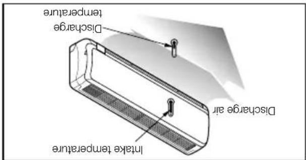
In take temperature Discharge temperature Discharge air(Cooling) or reversely (Heating). Temperature and the discharge is more than 8^ C 3. Ensure the difference between the intake
discharge of air.
- Measure the temperature of the intake and
valve.
- Measure the pressure of the gas side service
system refrigerant charge:
Operate unit for 15\~20 minutes, then check the
C Evaluation of the performance
Tubing convection
text_image
Boltanti-vibration rubber.
conveyed to the hose, secure the unit with an
In the case when the variation of the unit is
assuming the influence of wind and earthquake.
the mounting base securely with a nail or wire
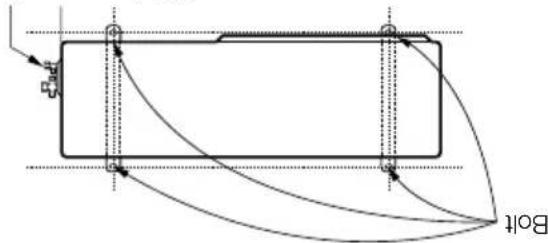
Anchor the outdoor unit with a bolt and nut of 0mm tightly and horizontally on a concrete or rigid mount. When installing on the wall, roof or rooftop, anchor
B Settlement of outdoor unit
time.
- Remove the batteries from the remote control if the system is not going to be used for a long
rechargeable batteries.
- Use 2 AAA(1.5volt) batteries. Do not use
NOTE:
natural_image
Illustration of three hands performing a manual task with arrows indicating direction (no text or symbols)-
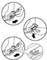
Reatched the cover by pushing it back into position.
-
Insernt new batteries making sure that the (+) and (-) of battery are installed correctly.
-
Remove the battery cover by pulling it according to the arrow direction.
A Prepare remote control
are fully open.
- Check that the gas and liquid side service valves
property connected.
- Check that all tubing and wiring have been
TEST RUNNING
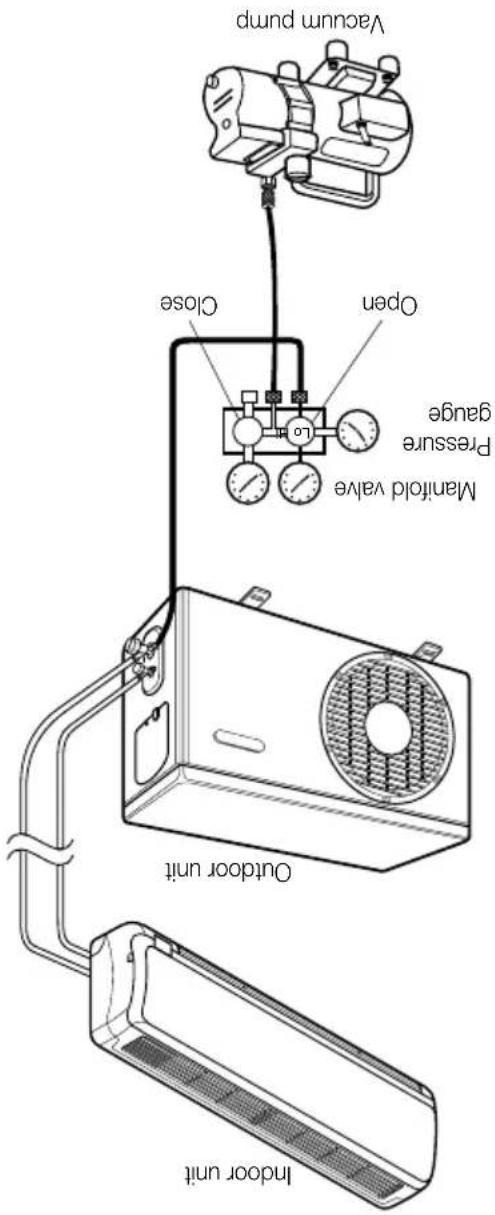
text_image
Vacuum pump Open Close Manifold valve Pressure gauge Outdoor unit Indoor unit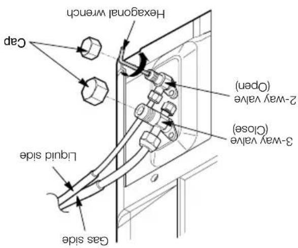
text_image
Gas side Liquid side Cap Hexagonal wrench 2-way valve (Open) 3-way valve (Close)■ With a service valve wrench, turn the valve stem of liquid side valve counter-cloxcwise to fully open the valve. ■ Turn the valve stem of gas side valve counter-cloxcwise to fully open the valve. ■ Loose the charge hose connected to the gas side service port slightly to release the pressure, then remove the hose. ■ Replace the flare nut and its bonnet on the gas side service port and fasten the flare nut securely with an adjustable wrench. This process is very important to prevent leakage from the system. ■ Replace the valve caps at both gas and liquid side service valves and fasten them tight. This completes air purging with a vacuum pump. The air conditioner is now ready to test run.
D Finishing the job
When the desired vacuum is reached, close the "Lo" know of the manifold valve and stop the vacuum pump.
| Required time for evacuation when 30 gal/hvacuum pump is used | |
| If tubing length is less than 10m (33 ft) | If tubing length is longer than 10m (33 ft) |
| 10 min. or more 15 min. or more | |
Connect the charge hose and described in the preceding steps to the vacuum pump to evacuate the tubing and indoor unit. Confirm the "Lo" know of the manifold valve is open. Then, run the vacuum pump. The operation time for evacuation varies with tubing length and capacity of the pump. The following table shows the time required for evacuation.
C Evacuation
(1) Remove the caps from the 2-way and 3-way valves. (2) Remove the service-port cap from the 3-way valves. (3) To open the 2-way valve turn the valve stem valves. about 2\~3 sec, and close it. (4) Apply a soap water or a liquid neutral detergent on the indoor unit connection or outdoor unit convictions by a soft brush to check for leakage of the connecting points of the piping. (5) If bubbles come out, the pipes have leakage.
Soap water method
AIR PURGING
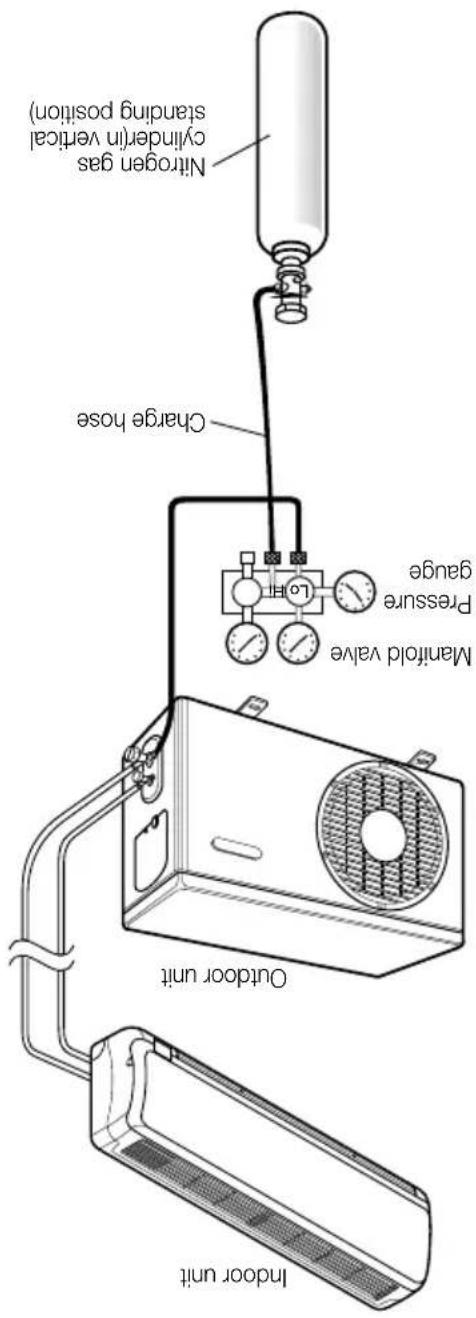
text_image
Nitrogen gas cylinderin vertical standing position) Charge hose Manifold valve Pressure gauge Outdoor unit Indoor unitDo a leak test of all joints of the tubing (both indoor and outdoor) and both gas and liquid side service valves. Bubbles indicate a leak. Be sure to wipe off the soap with a clean cloth. After the system is found to be free of leaks, relieve the nitrogen pressure by loosening the charge hose connector at the nitrogen cylinder. When the system pressure is reduced to normal, disconnect the hose from the cylinder.
To avoid nitrogen entering the refrigerant system in a liquid state, the top of the cylinder must be higher than its bottom when you pressure the system. Usually, the cylinder is used in a vertical standing position.
CAUTION
liquid soap.
Presuritize the system to no more than 150 P.S.LG. with dry nitrogen gas and close the cylinder valve when the gauge reading reached 150 P.S.LG. Next, test for leaks with
Be sure to use a manifold valve for air purging. If it is not available, use a stop valve for this purpose. The "Hi" knob of the manifold valve must always be kept close.
CAUTION
Connect the manifold valve(with pressure gauges) and dry nitrogen gas cylinder to this service port with charge hoses.
B Leak test
stage.
Check that each tube (both liquid and gas side tubes) between the indoor and outdoor units have been proper connected and all wiring for the test run has been completed. Remove the service valve caps from both the gas and the liquid side on the outdoor unit. Note that both the liquid and the gas side service valves on liquid and the outdoor unit are kept closed at this. The outdoor unit are kept closed at this
A Preparation
dwnd
Air purging with vacuum
Air and moisture remaining in the refrigerant system have undesirable effects as indicated below. Pressure in the system rises. ■ Operating current rises. ■ Cooling (or heating) efficiency drops. ■ Moisture in the refrigerant circuit may freeze and block capillary tubing. ■ Water may lead to corrosion of pants in the refrigeration system. Therefore, the indoor unit and tubing between the indoor and outdoor unit must be leak tested and evacuated to remove any noncondensables and moisture from the system.
Air purging
AIR PURGING
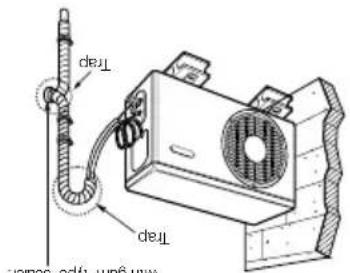
text_image
Max fan type sequen Trap TrapSeal a smell opening around the plings with gum type sealer.
equivalent.
Fix the piping onto the wall by saddle or
the room.
wall. Form a trap to prevent water entering
Secure the taped piping along the exterior
down to up.
Tape the piping, and connecting cable from
the following.
installed above the indoor unit perform
In cases where the Outdoor unit is
text_image
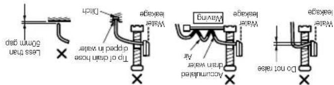
Less than 50mm gap Ditch Tip of drain hose dipped in water Water leakage Water leakage Maying Air Accumulated drain water Water leakage Males Water leakage DO not raise■ Do not make drain piping.
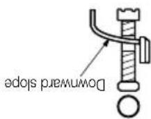
The drain hose should point downward for
easy drain flow.
C Drain piping
tom anlei
Jard is required to prevent water
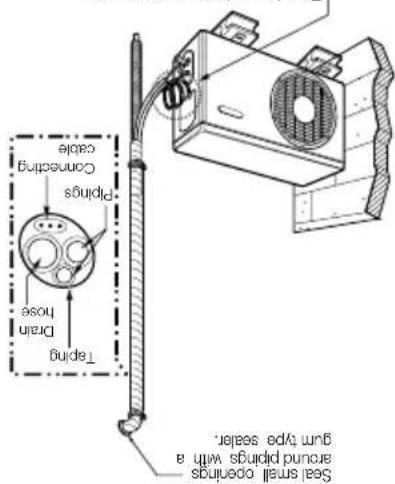
text_image
Seal snell openings around prinds with a gurn type sealer. Connecting cable Pirpings Drain hose Tapingwall using saddle or equivalent.
Secure the tapped piping along the exterior
connecting cable from down to up.
Tape the piping, drain hose and
the following.
installed below the indoor unit perform
In cases where the outdoor unit is
hose appropriate.
routed above the ground. Secure the drain
hose, the end of the drain outlet should be
If you want to connect an additional drain
kinds of vinyl tapes.
insulation material and secure fit with two
connecting portion of the indoor unit with
Form the piping by wrapping the
natural_image
Technical line drawing of a portable air conditioner unit with a fan and handle (no text or symbols)and goes out the drain exit.
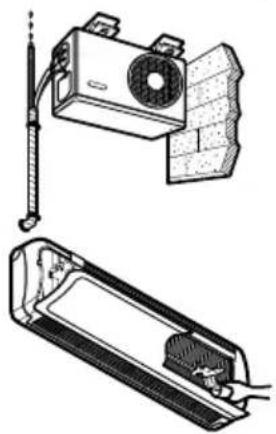
hose of the indoor unit without any leakage
Ensure the water flows through the drain
Pour a glass of water on the evaporator.
B To check the drainage.
text_image
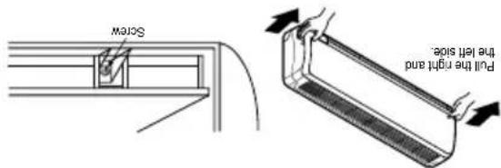
Screw pull the right and the left side.(18K, 24K, 26K Btu models: 3EA)
sides of the grille toward you and iff it off.
front panel. Pull the lower left and right
Remove the securing screws that retain the
the position(horizontally) by hand.
Set the air direction lovers up-and-down to
indoor unit cabinet.
unit, remove the front panel from the
To remove the front panel from the indoor
A
Form the piping
Checking the drainage
(9) The means for disconnection from a power supply shall be incorporated in the fixed wiring and have an air gap contact separation of at least 3mm in each active (phase)
normal function of the overload.
• Vibration of a magnetic switch, which will damage the contact point, fuse breaking, disturbance of the
8) The following would be caused by voltage drop.
7) Always install an earth leakage circuit breaker in a wet or moist area.
(Particulary note the relation between cable length and thickness. (Refer to page 11))
(6) Confirm that the cable thickness is as specified in the power source specification.
voltage marked on the name plate.
5) See to that the starting voltage is maintained at more than 90 percent of the rated
4) Confirm that electrical capability is sufficient.
3) Specification of power source.
are loose, if could cause burn-out of the wires.)
transportation. Check them and make sure that they are all tightly fastened. (If they
loose from vibrations to which the unit is subjected during the course of
2) The screw which fasten the wiring in the casing of electrical fittings are liable to come
COVER.
the method of wiring, be guided by the circuit diagram posted on the inside of control
1) Never fail to have an individual power circuit specifically for the air conditioner. As for
After the confirmation of the above conditions, prepare the wiring as follows:
CAUTION
text_image
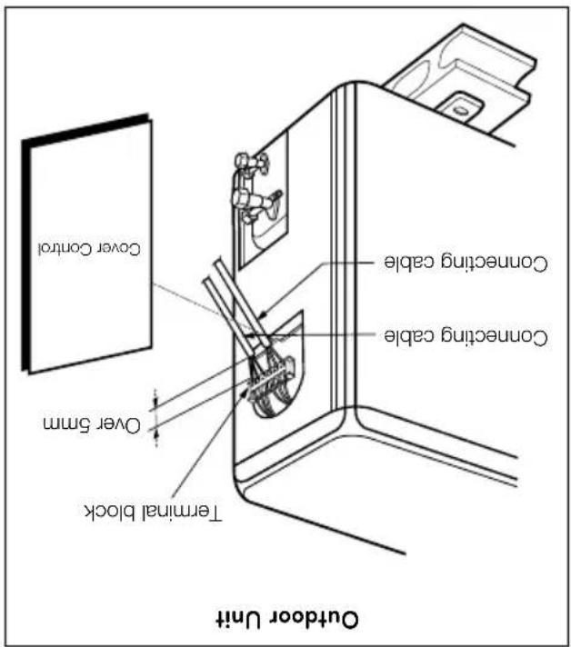
Cover Control Over 5mm Terminal block Concenting cable Concenting cable Outdoor Unitbe fitted.
adequately disconnect all supply lines must
and the unit. A disconnecting device to
25A (24K, 26K) between the power source
Use a recoginized circuit breaker 20A (18K),

position with the screw.
Refix the control cover to the original

the cord clamp.
Secure the cable onto the control board with

control board individually.
Connect the wires to the terminals on the
loosening the screw.
Remove the control cover from the unit by

outdoor unit
Connect the cable to the
Connect the cable from Indoor to outdoor unit.
■ Connect the cable to the indoor unit by connecting the wires to the terminals on the control board individually according to the outdoor unit connection.
(Ensure that the color of the wires of the outdoor unit and the terminal No. are the same as those of the indoor unit.)
• Cooling model (1.5, 2.0 Ton)
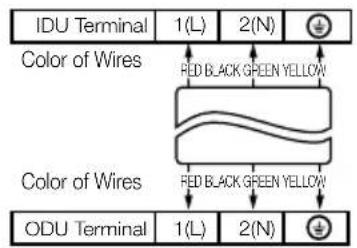
text_image
IDU Terminal 1(L) 2(N) Color of Wires FED BLACK GREEN YELLOW Color of Wires FED BLACK GREEN YELLOW ODU Terminal 1(L) 2(N)• Cooling model (0.75, 0.9, 1.0 Ton)
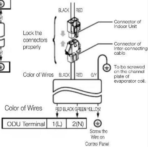
text_image
Lock the connectors properly Color of Wires Black RED Connector of Indoor Unit Connector of Inter-connecting cable To be screwed on the channel plate of evaporator coil. Color of Wires RED BLACK GREEN YELLOW ODU Terminal 1(L) 2(N) Screw the Wire on Control Panel- Heat pump model
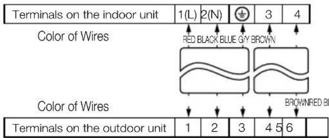
text_image
Terminals on the indoor unit 1(L) 2(N) 3 4 Color of Wires RED BLACK BLUE GAY BROWN Color of Wires BROWNRED BL Terminals on the outdoor unit 1 2 3 4 5 6CAUTION
The power cord connected to the indoor unit should be compiled with the following specifications (Type H05VV-F approved by HAR or SAA).
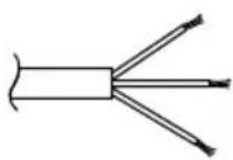
| Capacity (Btu/h) | NORMAL CROSS -SECTIONAL AREA |
| 9K, 12K | 1.0mm ^2 |
| 18K | 1.5mm ^2 |
| 24K26K | 2.5mm ^2 |
The power connecting cable connected to the indoor and outdoor unit should be compiled with the following specifications
(Type H07RN-F approved by HAR or SAA).
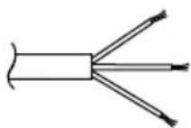
| Capacity (Btu/h) | NORMAL CROSS -SECTIONAL AREA |
| 9K, 12K | 1.0mm ^2 |
| 18K | 2.0mm ^2 |
| 24K26K | 2.5mm ^2 |
The connecting cable connected to the indoor and outdoor unit should be compiled with the following specifications
(Type H07RN-F approved by HAR or SAA).
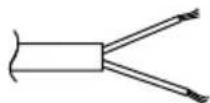
NORMAL CROSS-SECTIONAL AREA 0.75mm ^2
The length of the power supply cord should be over 1.8m measured from the power supply cord entry of the cabinet to the middle of the live pin of the plug.
CAUTION
If a power plug is not to be used, provide a circuit breaker between power source and the unit as shown below.
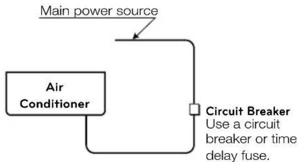
flowchart
graph TD
    A["Main power source"] --> B["Air Conditioner"]
    B --> C["Circuit Breaker\nUse a circuit breaker or time delay fuse."]
text_image
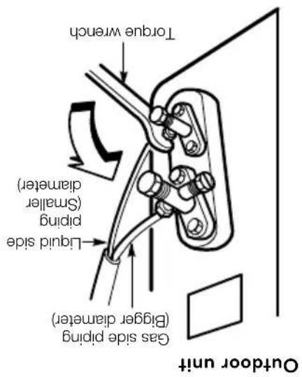
Torque wrench Liquid side piping (Smaller diameter) Gas side piping (Bigger diameter) Outdoor unit| Capacity(Btu/h) | Pipe Size(Torque) | |
| GAS Liquid | 1/4" [1.8kg·m] 3/8"[4.2kg·m] | |
| 9K, 12K18K, 24K, 26K | 1/2"[5.5kg·m] 5/8"[6.6kg·m] | 1/4"[1.8kg·m] |
When tightening the face nut with torque wrench, ensure the direction for tightening follows the arrow on the wrench.
B Finally, tighten the flare nut with torque wrench until the wrench clicks.

natural_image
Technical line drawing of a mechanical assembly with bolts and a nut (no text or symbols)☑ Align the center of the pipygs and sufficiently tighten the flare nut by hand.
Connection of the pipes-Outdoor
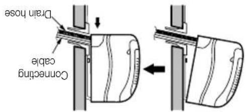
Press the lower left and right sides of the unit against the installation plate until the hooks engage into their slots (clicking sound).
text_image
Drain hose Concenting cableEnsure that the hooks are properly seated on the installation plate by moving it left and right.
Remove the spacer.
Indoor unit installation

text_image
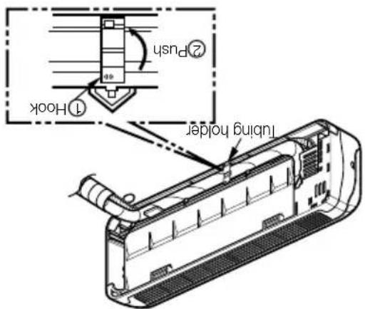
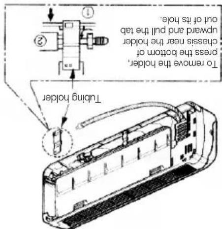
① Hook ② Push Lubing holderHook the edge of tubing holder to tap on chassis and push the bottom of tubing holder to be engaged at the bottom of chassis.
Set the pipsings and the drain hose to the back of the chassis with the tubing holder.

text_image
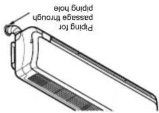
binding for passage through binding holeH Requote the pipsings and the drain hose across the back of the chassis.
text_image
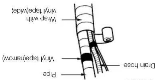
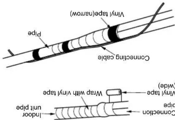
Wrap with vinyl tape(wide) Vinyl tape(narrow) Drain hose PipeBundle the piping and drain hose together by wrapping them with cloth tape over the range within which they fit into the rear piping housing
FLAIRING WORK AND CONNECTION OF PILING
text_image
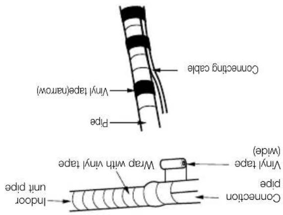
Converting cable Vinyl tape(narrow) Pipe Wrap with vinyl tape Vinyl tape (wide) Indoor pipe pin t pipe■ Wrap the area which accommodates the rear piping housing section with vinyl tape.
text_image
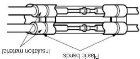
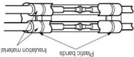
Plastic bands Insulation materialOverlap the connection pipe heat insulation and the indoor unit pipe heat insulation material. Bind them together with vinyl tape so that there is no gap.
6 Wrap the insulation material around the connecting portion.
text_image
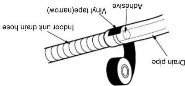
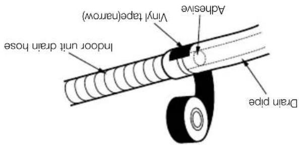
Vinyl tape(narrow) Adhesive Indoor unit drain hose Drain pipeWhen extending the drain hose at the indoor unit. Install the drain pipe.
| Capacity (Btu/h) | Pipe Size[Torque] | |
| 9K, 12K 18K, 24K, 26K | 1/2" [5.5kg·m] 5/8"[6.6kg·m] | 1/4" [1.8kg·m] 3/8"[4.2kg·m] |
| GAS LIQUID | ||
text_image
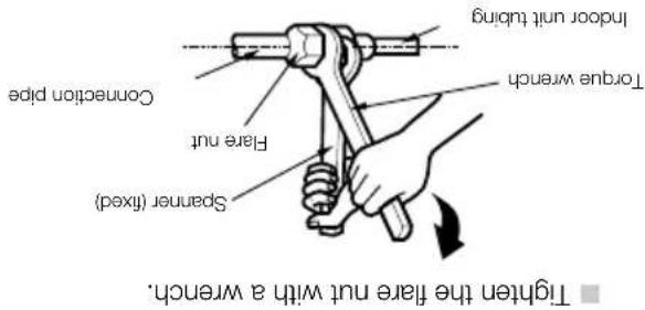
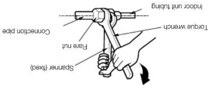
Tighten the flare nut with a wrench. Scanner (fixed) Fare nut Convection pipe Torque wrench Indoor unit tubing Topped joint tubing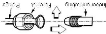
text_image
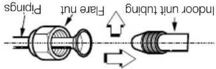
Pirpings Flare nut indoor unit tubing- Align the center of the pipyngs and sufficiently tighten the flare nut by hand.
F Connecting the pips to the indoor unit and the drain hose to drain pipe.
text_image
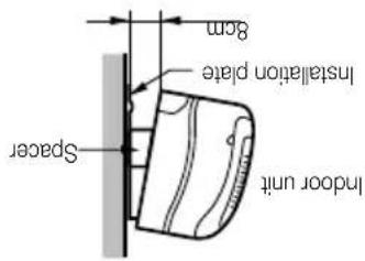
8cm Installation plate Spacer Indoor unit- Hang the indoor unit from the hooks at the top of the installation plate.
- Insert the spacer etc. between the indoor unit and the installation plate and separate the bottom of the indoor unit from the wall.
E Indoor unit installation
natural_image
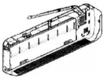
Technical line drawing of a mechanical device with no visible text or symbols- Connecting cable
D Tape the drain hose and the connecting cable.
C Insert the connecting cable into the indoor unit. Don't connect the cable to the indoor unit. Make a small loop with the cable for easy connection later.
FLAIRING WORK AND CONNECTION OF PILING
text_image
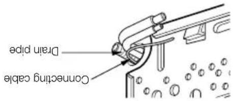
Drain pipe Connecting cableB Insert the piping, drain hose and the connecting cable into the piping hole.
natural_image
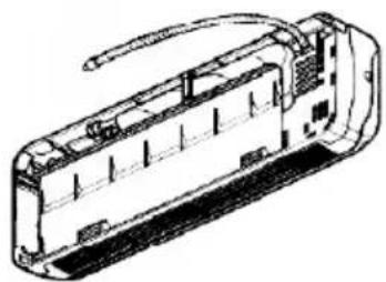
Technical line drawing of a rectangular electronic device with internal components and wiring (no text or symbols)Route the indoor tubing and the drain hose to the required piping hole position.
For right rear piping
text_image
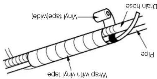
Vinyl tape(wide) Drain hose Pipe Wrap with vinyl tape■ Bundle the piping and drain hose together by wrapping them with vinyl tape over the range within which they fit into the rear piping housing section.
text_image
Vinyl tape(narrow) Connecting cable Pipe Wrap with vinyl tape Vinyl tape (wide) Indoor pipe Unit pipe■ Wrap the area which accommodates the rear piping housing section with vinyl tape.
text_image
Plastic bands Insulation materialOverlap the connection pipe insulation material and indoor unit pipe insulation material. Bind them together with vinyl tape so that thee is no gap.
F Wrap the insulation material around the connecting portion.
text_image
Vinyl tape(narrow) Adhesive Indoor unit drain hose Drain pipe■ When extending the drain hose at the indoor unit, install the drain pipe.
| Capacity(Btu/h) | Pipe Size[Torque] | |
| GAS Liquid | ||
| 9K, 12K18K, 24K, 26K | 1/2"[5.5kg·m]5/8"[6.6kg·m] | 1/4"[1.8kg·m]3/8"[4.2kg·m] |
text_image
Window unit tubing Indoor unit tubing Force wrench Convection pipe Flare nut Spanner (fixed)Tighen the flare nut with a wrench.
FLAIRING WORK AND CONNECTION OF PILING
text_image
Pirings Flare nut indoor unit tubing- Allign the center of the pipings and sufficiently tighten the flare nut by hand.

Press the lower left and right sides of the unit against the installation plate until the hooks engage into their slots (clicking-sound).
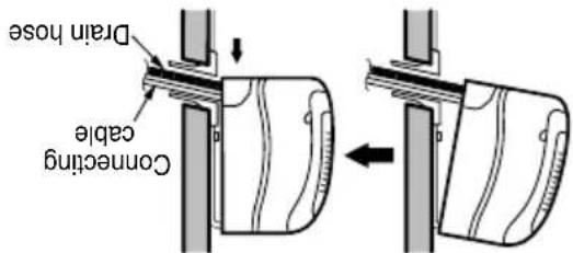
text_image
Drain hose Connecting cableHook the indoor unit onto the upper portion of the installation plate. Engage the two hooks of the rear top of the indoor unit with the upper edge of the installation plate. Ensure that the hooks are properly seated on the installation plate by moving it left and right

NOTE: If the clean house is routed inside the room, insulate the hose with an insulation material, so that dripping from "sweating" (condensation) will not damage furniture or floors. *Forced polyethylene or equivalent is recommended.
text_image
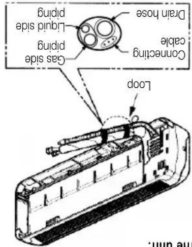
Gas side piping Liquid side piping Drain hose Connecting cable LoopC Tape the tubing, drain hose and the connecting cable. Be sure that the drain hose is located at the lowest side of the bundle. Locating at the upper side can cause drain pan to overflow inside the unit.
■ Do not connect the cable to the indoor unit. ■ Make a small loop with the cable for easy connection later.

text_image
B Insert the connecting cable into the indoor unit from the outdoor unit through the piping hole.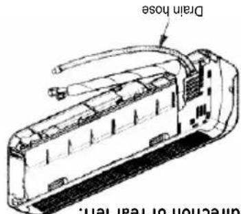
text_image
Drain hose direction of rear left.Route the indoor tubing and the drain hose in the direction of rear left.
For left rear piping
natural_image
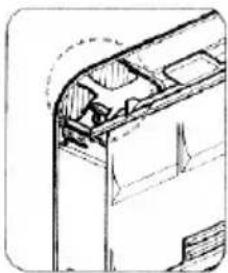
Technical line drawing of a mechanical assembly or bracket (no text or symbols)When install, make sure that the remaining parts must be removed clearly so as not to damage the piping and drain hose, especially power cord and connecting cable.
CAUTION
text_image
To remove the holder, press the bottom of upward and pull the tab out of its hole. Tubing holder■ Preparing the indoor unit's piping and drain hose for installation through the wall. ■ Remove the plastic tubing retainer (see illustration below) and pull the tubing and drain hose away from chassis. ■ Replace the plastic tubing holder in the original position.
indoor
Connection of piping-
FLAIRING WORK AND CONNECTION OF PILING
text_image
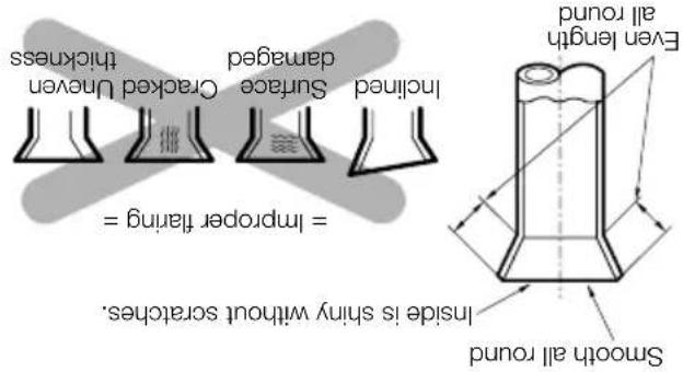
Smooth all round Inside is shiny without scratches. = Improper flaring = Cracked Unven thickness Surface damaged InclosedCompare the fared work with figure below. If there is noted to be defective, cut off the fared section and do faring work again.
text_image
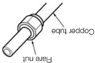
Copper tube Flare nutRemove flare nuts attached to indoor and outdoor unit, then put them on pipe/tube having completed bur removal. (not possible to put them on after fanning work)
C Putting nut on
text_image
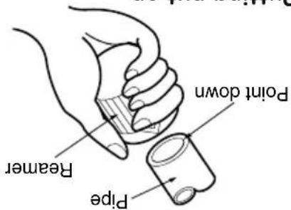
Point down Reamer PipeCompletely remove all burs from the cut cross section of pipe/tube. Put the end of the copper tube/pipe in a downward direction as you remove burs in order to avoid dropping burs into the tubing.
ECheck
B Burns removal
text_image
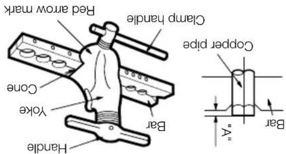
Red arrow mark Clamp handle Copper pipe Yoke Cone Bar Handle BARFirmly hold copper pipe in a die in the dimension shown in the table above.
| Outside diameter | A | |
| mm | inch | mm |
| 06.35 | 1/4 | 0~0.5 |
| 09.52 | 3/8 | 0~0.5 |
| 012.7 | 1/2 | 0~0.5 |
| 015.88 | 5/8 | 0~1.0 |
Cany out faring work using faring tool as shown below.
D Flaring work
text_image
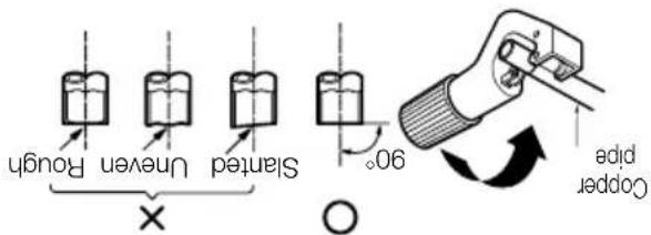
Started Uneven Rough 90° Copper pipeCut the pipes a little longer than measured distance. Cut the cable 1.5m longer than the pipe length.
Use the piping kit accessory or the pipes purchased locally. Measure the distance between the indoor and the outdoor unit.
A Cut the pipes and the cable
Main cause for gas leakage is due to defect in faring work. Cavity out correct faring work in the following procedure.
Flaring work
FLAIRING WORK AND CONNECTION OF PILING
text_image
Drain Pipe Drain Pan Outdoor Unit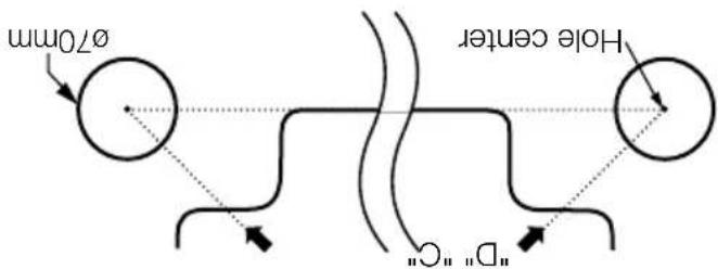
text_image
Ø70mm Hole center "D" "C"Left rear piping Right rear piping
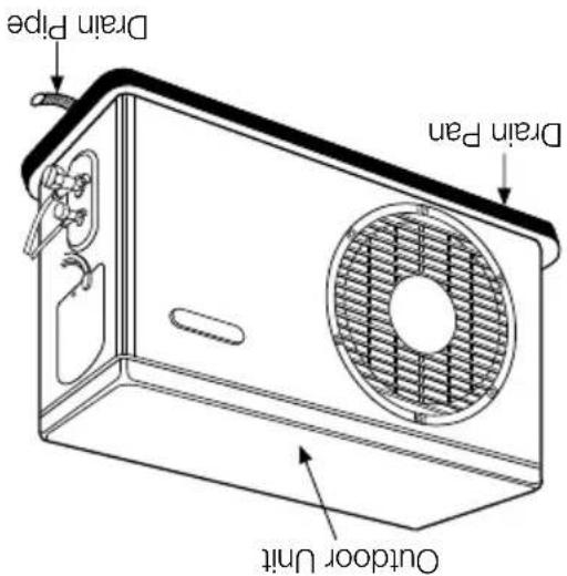
Drain pan along with drain pipe (as shown below) can be used to drain the water accumulated in the outdoor during the Heat Mode.
(Heat Pump) Usage of Drain Pan
B Measure the wall and mark the centerline. It is also important to use caution concerning the location of the installation plate-routing of the wiring to power outlets is through the walls typically. Drilling the hole through the wall for piping connections must be done safely.
• Make sure that the chilled hole in the wall is property sealed (using a proper sealant, for example cement, plaster of parts etc.) after passing the installation pipe, drainage pipe and the inter connecting cable.
CAUTION
text_image
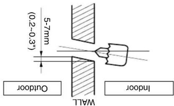
5-7mm (0.2~0.3") OUTDOOR WALL Indooroutdoor side.
Drill the piping hole with a 70mm hole core drill. Drill the piping hole at either the right or the left with the hole slightly started to the
text_image
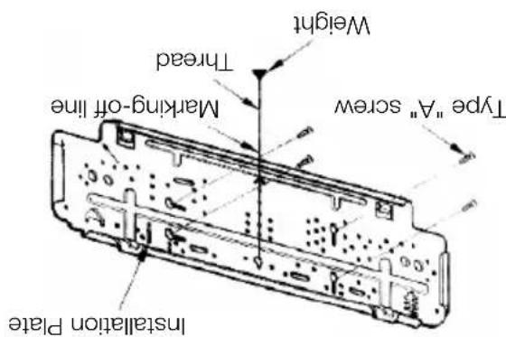
Installation Plate Type "A" screw marking-off line Thread WeightMount the installation plate horizontally by aliguing the centriline using a level.
Mount the installation plate on the wall with four type A screws. If mounting the unit on a concrete wall, use anchor bolts.
The wall you select should be strong and solid enough to prevent vibration.
How to fix installation plate Drill a hole in the wall
INSTALLATION OF INDOOR & OUTDOOR UNIT
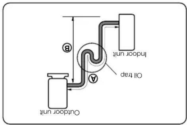
• Oil trap should be installed every 5\~7 meters. • Capacity is based on standard length and maximum allowance length is on the basis of reliability.
CAUTION
In case more than 5m
text_image
Outdoor unit Oil trap Indoor unit B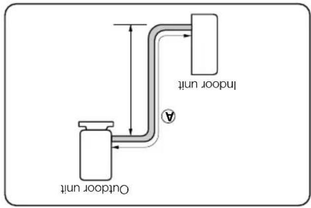
text_image
Outdoor unit Indoor unit| Capacity (Btu/h) | Pipe Size | Standard Length (m) | Max. Length (g/m) | Additional Refrigerant (g/m) | |
| CAS | Liquid | ||||
| 9K | 3/8" | 1/4" | 3 to 5 | 20 | 20 |
| 9K, 12K, 18K (50HZ) | 1/2" | 1/4" | 3 to 5 | 20 | 20 |
| 18K (60HZ) | 5/8" | 1/4" | 3 to 5 | 20 | 20 |
| 24K Cooling | 5/8" | 3/8" | 3 to 5 | 20 | 20 |
| 24K, 26K Cooling & Heat Pump | 5/8" | 3/8" | 3 to 5 | 20 | 20 |
Piping length and elevation
If the outdoor unit is installed on a roof structure, be sure to level the unit. Ensure the roof structure and anchoring method are adequate for the unit location. Consult local codes regarding rooftop mounting.
Rooftop installation
text_image
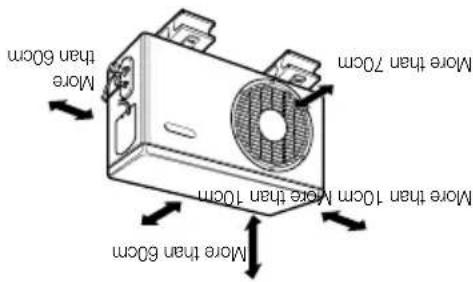
More than 10cm More than 10cm More than 7cm More than 50cmdisturb neighbors.
space. Do not place animals and plants in the path of the warm air. Take the air conditioner weight into account and select a place where noise and vibration are minimum. Select a place so that the warm air and noise from the air conditioner do not
If an awning is built over the unit to prevent direct sunlight or rain exposure, make sure that heat radiation from the condenser is not restricted. Ensure that the space around the back and sides is more than 10cm. The front of the unit should have more than 70cm of
Outdoor Unit
text_image
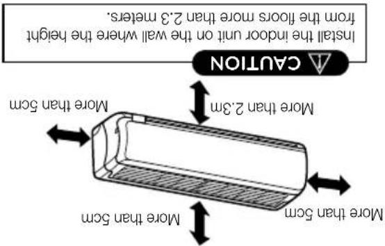
Install the indoor unit on the wall where the height from the floors more than 2.3 meters. COUTION More than 2.3m More than 5cm More than 5cmUnit. Select a place where there are no obstacles in front of the unit. Make sure that condensation drainage can be conveniently routed away. Do not install near a doorway. Ensure that the space around the left and right of the unit is more than 5cm. The unit should be installed as high on the wall as possible, allowing a minimum of 5cm from ceiling. Use a stud harder to locate studs to prevent unnecessary damage to the wall.
Do not have any heat or steam near the
A Indoor Unit
Select the best location
Read completely, then follow step by step.
INSTALLATION OF INDOOR & OUTDOOR UNIT
| S.No. | Required Tools |
| 1 | Level Gauge |
| 2 | Screw Driver |
| 3 | Electric Drill |
| 4 | Hole Core Drill (Dia-Tomm) |
| 5 | Flaring Tool Set |
| 6 | Specified torque wrenches 1.8kg.m, 4.2kg.m, 5.5kg.m, 6.6kg.m(Different depending on model no.) |
| 7 | Spanner (Half Union) |
| 8 | A glass of water |
| 9 | Hexagonal Wrench |
| 10 | Gas-Leak Detector |
| 11 | Vacuum Pump |
| 12 | Gauge Manifold |
| 13 | Owner's Manual |
| 14 | Thermometer |
Installation Tools
| Type, A, Screw Quantity | Shape Others | |
| Sleeve | ||
| Bushing Sleeve | ||
| Putty (Gum type sealer) | ||
| Vinyl tape (Wide) | ||
| Gas side piping | ||
| Liquid side piping | ||
| Additional drain pipe | ||
| Vinyl tape (Narrow) | ||
| Saddle |
Installation parts you must purchase
| Type, A, Screw Quantity | Shape Others | |
| Type, A, Screw | 4 | [G353] |
| Installation Plate | 1 | 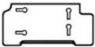 |
| Type, B, Screw | 2 | [8CKD] |
| Holder Remote Control | 1 | [MZQ] |
| • Paper pattern for installation. • Owner's Manual • Installation Manual | ||
Installation parts provided with the unit
INSTALLATION PARTS
20 Test running
18 Air purging
bidid
17 Checking the drainage and forming the
unit and outdoor unit
15 Connecting the cable between indoor
14 Convention of piping (Outdoor)
12 For left rear piping
11 For right rear piping
11 Connection of piping (indoor)
10 Flaring Work and Connection of Piping
8 Installation of indoor & Outdoor Unit
8 INSTALATION
7 Required Tools
6 installation Parts you must purchase
6 installation Parts provided with the Unit
6 INSTALLATION PARTS 9
TABLE OF CONTENTS
- Always check for gas (refrigerant) leakage after installation or repair of product. - Low refrigerant levels may cause failure of product. - Install the drain house to ensure that water is drained away properly. - A bad connection may cause water leakage. - Keep level even when installing the product. - To avoid vibration or water leakage. - Do not install the product where the noise or hot air from the outdoor unit could damage the weigh- borhoods. - Use two or more people to lift and transport the product. - At may cause a problem for your neighbors. - Avoid personal injury. - Do not install the product where it will be exposed to sea wind (salt spray) directly. - It may cause corrosion on the product. Corrosion, particularly on the condenser and evaporator fins, could cause product malfunction or inefficient operation.
installation
i CAVTION
• Do not store or use flammable gas or combustibles near the product. - There is risk of fire or failure of product.
Operation
- Do not install the product on a defective installation stand. - It may cause injury, accident, or damage to the product. - Be sure the installation area does not deteriorate with age. - If the base collapses, the air conditioner could fall with it, causing property damage, product failure, and personal injury.
- Do not use a defective or underated circuit breaker. Use this appliance on a dedicated circuit. - For electrical work, contact the dealer, seller, a qualified electrician, or an Authorized Service Center. - Do not disassemble or repair the product. There is risk of fire or electric shock. - Always ground the product. - There is risk of fire or electric shock. - Use the correctly rated breaker or fuse. - There is risk of fire or electric shock. - Improper wiring or installation may cause fire or electric shock. - Always install a dedicated circuit and breaker. - Implement the panel and the cover of control box securely. - There is risk of fire or electric shock. - Use the correctly rated breaker or fuse. - There is risk of fire or electric shock. - Do not modify or extend the power cable. - There is risk of fire or electric shock. - Do not let the air conditioner run for a long time when the humidity is very high and a door or a win- - Dow is left open. - Moisture may condense and wet or damage furniture. - Sharp edges could cause injury. Be especially careful of the case edges and the fins on the con- denser and evaporator. - For installation, always contact the dealer or an Authorized Service Center. - There is risk of fire, electric shock, explosion, or injury.
instal|ation
• Installation or repairs made by unqualified persons can result in hazards to you and others. • The information contained in the manual is intended for use by a qualified service technician familiar with safety procedures and equipped with the proper tools and test instruments. • Failure to carefully read and follow all instructions in this manual can result in equipment mail- function, property damage, personal injury and/or death.
WARNING

It can result in minor injury or product damage when the directions are ignored
i CAVTION
It can result in serious injury or death when the directions are ignored
i WARMING
performance of your product
Always comply with the following precautions to avoid dangerous situations and ensure peak
READ ALL INSTRUCTIONS BEFORE USING THE APPLICATION.
IMPORTANT SAFETY INSTRUMENTS
Date of purchase :
Dealer's name :
You can find them on a label on the side of each unit.
Serial number:
Model number:
Staple your receipt to this page in case you need it to prove the date of purchase or for warranty purposes. Write the model number and the serial number here:
For your records
Do not cool excessively indoors. This may be harmful for your health and may consume more electricity. (Recommended 24°C is suitable for human body) • Clean the air filter once every 2 weeks. Dust and impurities collected in the air filter may block the air flow or weaken the cooling / dehumidifying functions. (Refer page no. 21 and 22 owner's manual) • Clean the air filter once every 2 weeks. Dust and impurities collected in the air filter may block the air flow or weaken the cooling / dehumidifying functions. (Refer page no. 21 and 22 owner's manual) • Clean the air filter once every 2 weeks. Dust and impurities collected in the air filter may block the air flow or weaken the cooling / dehumidifying functions. (Refer page no. 21 and 32 owner's manual) • Clean the air filter once every 2 weeks. Dust and impurities collected in the air filter may block the air flow or weaken the cooling / dehumidifying functions. (Refer page no. 21 and 32 owner's manual) • Clean the air filter once every 2 weeks. Dust and impurities collected in the air filter may block the air flow or weaken the cooling / dehumidifying functions. (Refer page no. 1 and 22 owner's manual) • Clean the air filter once every 2 weeks. Dust and impurities collected in the air filter may block the air flow or weaken the cooling / dehumidifying functions. (Refer page no. 1 and 22 owner's manual) • Clean the air filter once every 2 weeks. Dust and impurities collected in the air filter may block the air flow or weaken the cooling / dehumidifying functions. (Refer page no. 15 and 22 owner's manual) • Clean the air filter once every 2 weeks. Dust and impurities collected in the air filter may block the air flow or weaken the cooling / dehumidifying functions. (Refer page no. 15 and 22 owner's manual) • Clean the air filter once every 2 weeks. Dust and impurities collected in the air filter may block the air flow or weaken the cooling / dehumidifying functions. (Refer page n o. 1 and 22 owner's manual) • Clean the air filter once every 2 weeks. Dust and impurities collected in the air filter may block the air flow or weaken the cooling / dehumidifying functions. (Refer page n o. 1 and 22 owner's manual) • Clean the air filter once every 2 weeks. Dust and impurities collected in the air filter may block the air flow or weaken the cooling / dehumidifying functions. (Refer page no. 1 and 22 owner's manual) • Clean the air filter once every 2 weeks. Dust and impurities collected in the air filter may block the air flow or weaken the cooling / dehumidifying functions. (Referr page no. 21 and 22 owner's manual) • Clean the air filter once every 2 weeks. Dust and impurities collected in the air filter may block the air flow or weaken the cooling / dehumidifying functions. (Refer page no. 21 and 22 owner's manual) • Clean the air filter once every 2 weeks. Dust and impurities collected in the air filter may block the air flow or weaken the cooling / dehumidizing functions. (Refer page no. 21 and 22 owner's manual) • Clean the air filter once every 2 weeks. Dust and impurities collected in the air filter may block the air flow or weaken the cooling / dehumidifying functions. (Refer page no. 21 and 22 owner's manual) • Clean the air filter once every 2 weeks. Dust and impurities collected in the air filter may block the air flow or weaken the cooling, dehumidifying functions. (Refer page no. 21 and 22 owner's manual) • Clean the air filter once every 2 weeks. Dust and impurities collected in the air filter may block the air flow or weaken the cooling, dehumidifying functions. (Refer page no. 21 and 22 owner's manual) • Clean the air filter once every 2 weeks. Dust and impurities collected in the air filter may block the air flow, dehumidifying functions, etc. • Clean the air filter once every 2 weeks. • Clean the air filter once every 2 weeks. • Clean the air filter once every 2 weeks. • Clean the air filter once every 2 weeks. • Clean the air filter once every 2 weeks. • Clean the air filter once every 2 weeks. • Clean the air filter once every 2 weeks. • Clean the air filter once every 2 weeks. • Clean the air filter once every 2 weeks. • Clean the air filter once every 2 weeks • Clean the air filter once every 2 weeks. • Clean the air filter once every 2 weeks. • Clean the air filter once every 2 weeks. • Clean the air filter once every 2 weeks. • Clean the air filter once every 2 weeks. • Clean the air filter once every 2 weeks. • Clean the air filter once every 2 weeks. • Clean the air filter once every 2 weeks. • Clean the air filter once every 2 weeks. - Clean the air filter once every 2 weeks. - Clean the air filter once every 2 weeks. - Clean the air filter once every 2 weeks. - Clean the air filter once every 2 weeks. - Clean the air filter once every 2 weeks. - Clean the air filter once every 2 weeks. - Clean the air filter once every 2 weeks. - Clean the air filter once every 2 weeks. - Clean the air filter once every 2 weeks. - Greenhouse Air Quality Control System - Greenhouse Air Quality Control System - Greenhouse Air Quality Control System - Greenhouse Air Quality Control System - Greenhouse Air Quality Control System - Greenhouse Air Quality Control System - Greenhouse Air Quality Control System - Greenhouse Air Quality Control System - Greenhouse Air Quality Control System - Greenhouse Air Quality Control System - Greenhouse Air Quality Control System - Greenhouse Air Quality Control System - Greenhouse Air Quality Control System - Greenhouse AI Systems - Greenhouse AI Systems - Greenhouse AI Systems - Greenhouse AI Systems - Greenhouse AI Systems - Greenhouse AI Systems - Greenhouse AI Systems - Greenhouse AI Systems - Greenhouse AI Systems - Greenhouse AI Systems - Greenhouse AI Systems - Greenhouse AI Systems - Greenhouse AI Systems - Greenhouse AI Systems - Greenhouse AI Systems - Greenhouse AI Systems - Greenhouse AI Systems - Greenouse AI Systems - Greenouse AI Systems - Greenouse AI Systems - Greenouse AI Systems - Greenouse AI Systems - Greenouse AI Systems - Greenouse AI Systems - Greenouse AI Systems - Greenouse AI Systems - Greenouse AI Systems - Greenouse AI Systems - Greenouse AI Systems - Greenouse AI Systems - Greenouse AI Systems - Greenouse AI Systems - Greenouse AI Systems - Greenouse AI Systems The Air Quality Control System is suitable for your health and may consume more electricity. (Recommended 24°C is suitable for human body)
below:
Here are some tips that will help you minimize the power consumption when you use the air conditloner. You can use your air conditloner more efficiently by referring to the instructions
TIPS FOR SAVING ENERGY
www.18.com
Tel: 0120-2560900 Fax: 0120-2560957
Greater Noida - 201 306 (U.P.) INDI A
Registered Office: Plot No. 51, Surajpur Karsna Road,
LC Electronics India Pvt. Ltd.
text_image
1- LG 24 x 7 CALL CENTER 1800-180-9999 ( toll free ) 5757554 service&live.com WwwLg.com Send sms) 3PP/No. MFL39754838
TYPE: WALL MOUNTED
future reference after reading it thoroughly.
- Please retain this installation manual for
standards by authorized personal only.
• Installation work must be performed in accordance with the national winding
performed by authorized personal on:Y.
- When the power cord is damaged, replacement work shall be
- Please read this installation manual completely before installing the product.