
Portege R400 - Laptop TOSHIBA - Free user manual and instructions
Find the device manual for free Portege R400 TOSHIBA in PDF.


User questions about Portege R400 TOSHIBA
0 question about this device. Answer the ones you know or ask your own.
Ask a new question about this device
Download the instructions for your Laptop in PDF format for free! Find your manual Portege R400 - TOSHIBA and take your electronic device back in hand. On this page are published all the documents necessary for the use of your device. Portege R400 by TOSHIBA.
USER MANUAL Portege R400 TOSHIBA
© 2006 by TOSHIBA Corporation. All rights reserved. Under the copyright laws, this manual cannot be reproduced in any form without the prior written permission of TOSHIBA. No patent liability is assumed, with respect to the use of the information contained herein.
TOSHIBA PORTÉGÉ M400 Portable Personal Computer User's Manual First edition February 2006
Copyright authority for music, movies, computer programs, data bases and other intellectual property covered by copyright laws belongs to the author or to the copyright owner. Copyrighted material can be reproduced only for personal use or use within the home. Any other use beyond that stipulated above (including conversion to digital format, alteration, transfer of copied material and distribution on a network) without the permission of the copyright owner is a violation of copyright or author's rights and is subject to civil damages or criminal action. Please comply with copyright laws in making any reproduction from this manual.
Disclaimer
This manual has been validated and reviewed for accuracy. The instructions and descriptions it contains are accurate for the TOSHIBA PORTÉGÉ M400 Portable Personal Computer at the time of this manual's production. However, succeeding computers and manuals are subject to change without notice. TOSHIBA assumes no liability for damages incurred directly or indirectly from errors, omissions or discrepancies between the computer and the manual.
Trademarks
IBM is a registered trademark and IBM PC is a trademark of International Business Machines Corporation.
Intel, Intel SpeedStep, Intel Core and Centrino are trademarks or registered trademarks of Intel Corporation.
Windows and Microsoft are registered trademarks of Microsoft Corporation.
Photo CD is a trademark of Eastman Kodak.
Sonic RecordNow! is a registered trademark of Sonic Solutions.
Bluetooth is a trademark owned by its proprietor and used by TOSHIBA under license.
i.LINK is trademark and registered trademark of Sony Corporation.
InterVideo and WinDVD are registered trademarks of InterVideo Inc.
WinDVD Creator is trademark of InterVideo Inc.
Other trademarks and registered trademarks not listed above may be used in this manual.
EU Declaration of Conformity
CE
This product is labelled with the CE Mark in accordance with the related European Directives, notably Electromagnetic Compatibility Directive 89/336/EEC for the notebook and the electronic accessories including the supplied power adapter, the Radio Equipment and Telecommunications Terminal Equipment Directive 99/5/EC in case of implemented telecommunication accessories and the Low Voltage Directive 73/23/EEC for the supplied power adapter.
CE Marking is the responsibility of TOSHIBA EUROPE GmbH,
Hammfelddamm 8,
41460 Neuss, Germany, phone +49-(0)-2131-158-01.
For a copy of the related CE Declaration of Conformity please refer to the following website: http://epps.toshiba-teg.com.
This product and the supplied accessories are designed to observe the related EMC (Electromagnetic Compatibility) and safety standards.
However, TOSHIBA cannot guarantee that this product still observes these EMC standards if accessories or cables not manufactured / distributed by TOSHIBA are connected or implemented. To avoid EMC problems in general, the following advice should be observed:
■Only CE marked accessories should be connected / implemented.
■Only best shielded cables should be connected.
Working environment
This product was designed to fulfill the EMC (Electromagnetic Compatibility) requirements for "residential, commercial and light industry environments".
The following environments are not approved:
■Industrial Environments (e.g. environments with a mains voltage of 380V).
In the following environments the use of this product can be restricted:
■Medical Environments: This product is not certified as a medical product according to the Medical Product Directive 93/42/EEC, but can be used in office areas where the use is not restricted. Please disable the wireless LAN or Bluetooth hardware in such areas as long this feature is not official supported by the operator of the related medical facility.
■Vehicle Environments: Please read the operator's manual of the vehicle manufacturer for further restrictions of use.
Aircraft Environments: Please follow the advice of the flight personnel regarding restrictions of use.
Any consequences resulting from the use of this product in working environments that are not approved or the use is restricted are not the responsibility of TOSHIBA Corporation. The consequences of the use of this product in those working environments may be:
■Interference with other devices or machines in the nearby surrounding area
■Malfunction of or data loss from this product caused by disturbances generated by other devices or machines in the nearby surrounding area
Furthermore, for general safety reasons, the use of this product in environments with explosive atmospheres is not permitted.
Modem warning notice
Conformity Statement
The equipment has been approved to [Commission Decision "CTR21"] for pan-European single terminal connection to the Public Switched Telephone Network (PSTN).
However, due to differences between the individual PSTNs provided in different countries/regions the approval does not, of itself, give an unconditional assurance of successful operation on every PSTN network termination point.
In the event of problems, you should contact your equipment supplier in the first instance.
Network Compatibility Statement
This product is designed to work with, and is compatible with the following networks. It has been tested to and found to conform with the additional requirements conditional in EG 201 121.
Germany ATAAB AN005, AN006, AN007, AN009, AN010 and DE03, 04, 05, 08, 09, 12, 14, 17
Greece ATAAB AN005, AN006 and GR01, 02, 03, 04
Portugal ATAAB AN001,005,006,007,011 and P03,04,08,10
Spain ATAAB AN005,007,012, and ES01
Switzerland ATAAB AN002
All other countries/regions ATAAB AN003,004
Specific switch settings or software setup are required for each network, please refer to the relevant sections of the user guide for more details.
The hookflash (timed break register recall) function is subject to separate national type approvals. It has not been tested for conformity to national type regulations, and no guarantee of successful operation of that specific function on specific national networks can be given.
Description on Laser specification
The optical drive, such as a DVD-ROM / CD-R/RW drive or DVD Super Multi drive, that is used in this computer is equipped with a laser device. A classification label with the following sentence is affixed to the surface of the drive.
CLASS 1 LASER PRODUCT
LASER KLASSE 1
LUOKAN 1 LASERLAITE
APPAREIL A LASER DE CLASSE 1
KLASS 1 LASER APPARAT
The drive with the above label is certified by the manufacturer that the drive complies with the requirement for laser product on the date of manufacturing pursuant to article 21 of Code of Federal Regulations by the United States of America, Department of Health & Human Services, Food and Drug Administration.
In other countries, the drive is certified to comply with the requirement pursuant to IEC 825 and EN60825 on class 1 laser product.
Depending on model, this computer is equipped with one of the optical drives from the following list:
Manufacturer Type
MATSUSHITA UJDA765
MATSUSHITA UJ-822
MATSUSHITA UJ-842
Preface
Congratulations on your purchase of the PORTÉGÉ M400 computer. This powerful notebook computer provides excellent expansion capability, including multimedia devices, and it is designed to provide years of reliable, high-performance computing.
This manual tells how to set up and begin using your PORTÉGÉ M400 computer. It also provides detailed information on configuring your computer, basic operations and care, using optional devices and troubleshooting.
If you are a new user of computers or if you're new to portable computing, first read over the Introduction and The Grand Tour chapters to familiarize yourself with the computer's features, components and accessory devices. Then read Getting Started for step-by-step instructions on setting up your computer.
If you are an experienced computer user, please continue reading the preface to learn how this manual is organized, then become acquainted with this manual by browsing through its pages. Be sure to look over the Special features section of the Introduction, to learn about features that are uncommon or unique to the computer and carefully read HW Setup.
If you are going to install PC cards or connect external devices such as a monitor, be sure to read Chapter 8, Optional Devices.
Manual contents
This manual is made up of the following.
Chapter 1, Introduction, is an overview of the computer's features, capabilities, and options.
Chapter 2, The Grand Tour, identifies the components of the computer and briefly explains how they function.
Chapter 3, Getting Started, provides a quick overview of how to begin operating your computer and gives tips on safety and designing your work area.
Chapter 4, Operating Basics, This chapter describes the basic operations of your computer and precautions when using it, as well as the handling of CD/DVD.
Chapter 5, The Keyboard, describes special keyboard functions including the keypad overlay and hot keys.
Chapter 6, Power and Power-Up Modes, gives details on the computer's power resources and battery save modes and how to set a password.
Chapter 7, HW Setup, explains how to configure the computer using the HW Setup program and TPM.
Chapter 8, Optional Devices, describes the optional hardware available.
Chapter 9, Troubleshooting, provides helpful information on how to perform some diagnostic tests, and suggests courses of action if the computer doesn't seem to be working properly.
Chapter 10, Legal Footnotes, provides Legal Footnotes information related to your computer.
The Appendixes provide technical information about your computer.
The Glossary defines general computer terminology and includes a list of acronyms used in the text.
The Index quickly directs you to the information contained in this manual.
Conventions
This manual uses the following formats to describe, identify, and highlight terms and operating procedures.
Abbreviations
On first appearance, and whenever necessary for clarity, abbreviations are enclosed in parentheses following their definition. For example: Read Only Memory (ROM). Acronyms are also defined in the Glossary.
Icons
Icons identify ports, dials, and other parts of your computer. The indicator panel also uses icons to identify the components it is providing information on.
Keys
The keyboard keys are used in the text to describe many computer operations. A distinctive typeface identifies the key top symbols as they appear on the keyboard. For example, Enter identifies the Enter key.
Key operation
Some operations require you to simultaneously use two or more keys. We identify such operations by the key top symbols separated by a plus sign (+). For example, Ctrl + C means you must hold down Ctrl and at the same time press C. If three keys are used, hold down the first two and at the same time press the third.
ABC
When procedures require an action such as clicking an icon or entering text, the icon's name or the text you are to type in is represented in the type face you see to the left.
Display
Names of windows or icons or text generated by the computer that appear on its display screen are presented in the type face you see to the left.
Messages
Messages are used in this manual to bring important information to your attention. Each type of message is identified as shown below.

Pay attention! A caution informs you that improper use of equipment or failure to follow instructions may cause data loss or damage your equipment.

Please read. A note is a hint or advice that helps you make best use of your equipment.

Indicates a potentially hazardous situation, which could result in death or serious injury, if you do not follow instructions.
General Precautions
TOSHIBA computers are designed to optimize safety, minimize strain and withstand the rigors of portability. However, certain precautions should be observed to further reduce the risk of personal injury or damage to the computer.
Be certain to read the general precautions below and to note the cautions included in the text of the manual.
Stress injury
Carefully read the Instruction Manual for Safety & Comfort. It contains information on prevention of stress injuries to your hands and wrists than can be caused by extensive keyboard use. Chapter 3, Getting Started, also includes information on work space design, posture and lighting that can help reduce physical stress.
Heat injury
Avoid prolonged physical contact with the computer. If the computer is used for long periods, its surface can become very warm. While the temperature will not feel hot to the touch, if you maintain physical contact with the computer for a long time (if you rest the computer on your lap, or if you keep your hands on the palm rest, for example) your skin might suffer low-heat injury.
If the computer has been used for a long time, avoid direct contact with the metal plate supporting the I/O ports. It can become hot.
The surface of the AC adaptor can become hot when in use. This condition does not indicate a malfunction. If you need to transport the AC adaptor, disconnect it and let it cool before moving it.
- Do not lay the AC adaptor on a material that is sensitive to heat. The material could be damaged.
Pressure or impact damage
Do not apply heavy pressure to the computer or subject it to strong impact. Excessive pressure or impact can cause damage to computer components or otherwise cause malfunctions.
PC card overheating
Some PC cards can become hot with prolonged use. Overheating of a PC card can result in errors or instability in the PC card operation. Also be careful when you remove a PC card that has been used for a long time.
Mobile phones
Use of mobile phones can interfere with the audio system. Computer operation is not impaired but it is recommended that a distance of 30 cm be maintained between the computer and a mobile phone in use.
Table of Contents
Preface
General Precautions
Chapter 1 Introduction
Equipment checklist.... 1-1
Features.... 1-3
Special features 1-10
Utilities.... 1-13
Options 1-17
Chapter 2 The Grand Tour
Front with the display closed 2-1
Left side 2-3
Right side 2-4
Back side.... 2-5
Underside 2-6
Front with the display open. 2-8
System indicators.... 2-11
Keyboard indicators. 2-12
USB floppy disk drive (optional) 2-13
Optical media drives 2-14
AC adaptor 2-16
Chapter 3 Getting Started
Setting up your work space. 3-1
Operating the computer in Tablet mode.... 3-6
Connecting the AC adaptor.... 3-7
Opening the display 3-10
Turning on the power 3-10
Starting up for the first time 3-11
Turning off the power.... 3-11
Restarting the computer 3-15
Restoring your preinstalled software 3-15
Chapter 4 Operating Basics
Using the Touch Pad 4-1
Using the Tablet PC Pen and Reserve Pen 4-2
Changing to the Tablet mode 4-8
Changing the screen orientation. 4-10
Using Accelerometer Utilities 4-12
Changing to the laptop mode 4-13
Using the Fingerprint Sensor 4-13
Using the USB floppy disk drive (optional) 4-20
Changing Ultra Slim Bay modules 4-21
Using optical media drives 4-23
Writing CDs on DVD-ROM / CD-R/RW drive 4-27
Writing CD/DVDs on DVD Super Multi drive 4-29
Media care 4-38
Sound System.... 4-39
Modem 4-41
Wireless communications 4-44
LAN 4-48
Cleaning the computer.... 4-49
Moving the computer 4-50
Using the Hard Disk Drive (HDD) Protection 4-51
Heat dispersal.... 4-53
Chapter 5 The Keyboard
Typewriter keys.... 5-1
Function keys: F1 ... F12 .... 5-2
Soft keys: Fn key combinations 5-2
Hot keys.... 5-3
Windows special keys 5-7
Keypad overlay 5-7
Generating ASCII characters. 5-9
Chapter 6 Power and Power-Up Modes
Power conditions 6-1
Power indicators.... 6-4
Battery types. 6-5
Care and use of the battery pack 6-7
Replacing the battery pack 6-14
TOSHIBA Password Utility. 6-16
Tablet mode.... 6-19
Power-up modes.... 6-19
Panel power on/off 6-20
System Auto Off 6-20
Chapter 7 HW Setup
Accessing HW Setup 7-1
HW Setup window 7-1
Configuring the Execute-Disable Bit Capability and TPM ..... 7-8
Chapter 8 Optional Devices
PC card 8-2
Bridge media slot 8-3
Memory expansion 8-9
Battery Pack 8-14
Universal AC Adaptor 8-14
Slice Expansion Battery.... 8-15
Battery Charger 8-17
HDD Kit (Serial-ATA).... 8-17
Ultra Slim Bay HDD Adaptor 8-19
USB FDD Kit 8-20
Tablet PC Pen 8-20
Reserve Pen 8-20
External monitor.... 8-21
i.LINK (IEEE1394) 8-21
TOSHIBA Express Port Replicator 8-23
Security lock 8-24
Chapter 9 Troubleshooting
Problem solving process. 9-1
Hardware and system checklist 9-3
TOSHIBA support 9-20
Chapter 10 Legal Footnotes
CPU*1 10-1
Memory (Main System)*2 10-2
Battery Life*3 10-2
HDD Drive Capacity*4. 10-2
LCD*5 10-3
Graphics Processor Unit ("GPU")*6 10-3
Wireless LAN*7 10-3
Non-applicable Icons*8 10-3
Copy Protection*9 10-3
Images*10 10-3
Appendix A Specifications
Physical Dimensions ...... A-1
Appendix B Display Controller and Modes
Display controller B-1
Video modes B-1
Appendix C Wireless LAN
Card Specifications C-1
Radio Characteristics. C-2
Supported Frequency Sub-bands. C-2
Appendix D TOSHIBA RAID
Windows Manual Setup D-2
Starting, Modifying and Ending the BIOS Setup Program ..... D-4
Appendix E Bluetooth wireless technology Interoperability
Bluetooth wireless technology and your Health ..... E-3
Regulatory statements....E-3
Appendix F AC Power Cord and Connectors
Certification agencies F-1
Appendix G TOSHIBA Anti-theft Protection Timer
Appendix H If your computer is stolen
Glossary
Index
Chapter 1
Introduction
This chapter provides an equipment checklist, and it identifies the computer's features, options and accessories.

Some of the features described in this manual may not function properly if you use an operating system that was not preinstalled by TOSHIBA.
Equipment checklist
Carefully unpack your computer. Save the box and packing materials for future use.
Hardware
Check to make sure you have all the following items:
■PORTÉGÉ M400 Portable Personal Computer
■AC adaptor and power cord (2-pin plug or 3-pin plug)
Tablet PC Pen
■Reserve Pen (Provided with some models)

The Tablet PC Pen is included in the accessory tray of the product when purchased together with spare pen tips and a tip removal tool.
For some models, a Reserve Pen is also included in the accessory tray of the product when purchased.
Software
Microsoft® Windows XP Tablet PC Edition
■The following software is preinstalled:
■Microsoft ^® Windows XP Tablet PC Edition
■Microsoft Internet Explorer
TOSHIBA Utilities
■TOSHIBA SD Memory Boot Utility
DVD Video Player
■TOSHIBA TouchPad On/Off Utility
TOSHIBA Power Saver
TOSHIBA Mobile Extension
TOSHIBA Assist
TOSHIBA ConfigFree
TOSHIBA Zooming Utility
■TOSHIBA PC Diagnostic Tool
TOSHIBA Controls
TOSHIBA Mic Effect
■TOSHIBA Password Utility
■TOSHIBA Rotation Utility
■TOSHIBA Accelerometer Utilities
■TOSHIBA Tablet Access Code Logon Utility
Fingerprint utility
■TOSHIBA Wireless Key Logon
Online manual
■Product Recovery DVD-ROM
Documentation
■ PORTÉGÉ M400 Portable Personal Computer User's Manual
■PORTÉGÉ M400 Quickstart
■Microsoft Windows XP Tablet PC Edition Getting Started manual
■Instruction Manual for Safety & Comfort
Warranty information
If any of the items are missing or damaged, contact your dealer immediately.
Features
The computer uses TOSHIBA's advanced Large Scale Integration (LSI), Complementary Metal-Oxide Semiconductor (CMOS) technology extensively to provide compact size, minimum weight, low power usage, and high reliability. This computer incorporates the following features and benefits:
Processor
Built-in The computer is equipped with one of the following Intel® processor
Intel ^® Core ^™ Duo Processor, which incorporates a 2MB level2 cache memory. It also supports Enhanced Intel ^® SpeedStep ^® Technology.
Intel ^® Core ^™ Solo Processor, which incorporates a 2MB level2 cache memory. It also supports Enhanced Intel ^® SpeedStep ^® Technology.

Some models in the range are equipped with Intel® Centrino® Duo Mobile Technology, which is based on three separate technologies of Intel® Core™ Duo processor, Intel® PRO/Wireless Network Connection, and Mobile Intel® 945 Express Chipset Family.
In addition, some models in the range are equipped with Intel® Centrino® Mobile Technology, which is based on three separate technologies of Intel® Core™ Solo processor, Intel® PRO/Wireless Network Connection, and Mobile Intel® 945 Express Chipset Family.
Legal Footnote (CPU)\*1
For more information on the Legal Footnote regarding CPU, please refer to the Legal Footnotes section in Chapter 10.
Memory
Slots 256, 512, 1,024 or 2,048 MB memory modules can be installed in the two memory slots for a maximum of 4,096 MB system memory.
Video RAM A maximum of 128 MB of RAM is provided for video display, with part of the main system memory being used for Video RAM.
Legal Footnote (Memory (Main System))\*2
For more information on the Legal Footnote regarding Memory (Main System), please refer to the Legal Footnotes section in Chapter 10.
Power
| Battery pack The computer is powered by one rechargeable lithium-ion battery pack. | |
| Slice Expansion Battery | This battery pack increases your computer's operating time when main battery pack is also installed. |
Legal Footnote (Battery Life)*3
| For more information on the Legal Footnote regarding Battery Life, please refer to the Legal Footnotes section in Chapter 10. |
| RTC battery | The internal RTC battery backs up the Real Time Clock (RTC) and calendar. |
| AC adaptor The AC adaptor provides power to the system and recharges the batteries when they are low. It comes with a detachable power cord which will either have a 2-pin or 3-pin plug enclosure. Because it is universal, it can receive a range of AC voltage from 100 to 240 volts; however, the output current varies among different models. Using the wrong model can damage your computer. Refer to the AC adaptor section in Chapter 2, The Grand Tour. |
Disks
| Hard disk drive Available in five sizes. |
| ■40.0 billion bytes (37.26 GB) |
| ■60.0 billion bytes (55.89 GB) |
| ■80.0 billion bytes (74.53 GB) |
| ■100.0 billion bytes (93.16 GB) |
| ■120.0 billion bytes (111.79 GB) |
| Part of the space in the hard disk drive is reserved as administration space. |
Legal Footnote (Hard Disk Drive Capacity) ^* 4
| For more information on the Legal Footnote regarding HDD Drive Capacity, please refer to the Legal Footnotes section in Chapter 10. |
Optical media drive

Computers in this series can be configured with an optical media drive installed in the Ultra Slim Bay. The available optical media drives are described below.
| DVD-ROM / CD-R/RW drive | Some models are equipped with a full-size, DVD-ROM / CD-R/RW drive module that lets you run CD/DVDs without using an adaptor. It reads DVD-ROMs at maximum 8 speed and CD-ROMs at maximum 24 speed. It writes CD-Rs at maximum 24 speed and CD-RWs at maximum 24 speed. The drive supports the following formats:■CD-R■CD-RW■DVD-ROM■DVD-Video■CD-DA■CD-Text■Photo CD^TM (single/multi-session)■CD-ROM Mode 1, Mode 2■CD-ROM XA Mode 2 (Form1, Form2)■Enhanced CD (CD-EXTRA)■Addressing Method 2 |
| DVD Super Multi drive | Some models are equipped with a full-size DVD Super Multi drive module that lets you record data to rewritable CD/DVDs as well as run either 12cm (4.72") or 8cm (3.15") CD/DVDs without using an adaptor. It reads DVD-ROMs at maximum 8 speed and CD-ROMs at maximum 24 speed. It writes CD-Rs at maximum 24 speed, CD-RWs at maximum 10 speed, DVD-Rs and DVD-RWs at maximum 2 speed, DVD+Rs and DVD+RWs at maximum 2.4 speed and DVD-RAM at maximum 2 speed. This drive supports the following formats in addition to the DVD-ROM / CD-R/RW drive.■DVD-R■DVD-RW■DVD+R■DVD+RW■DVD-RAM |
| DVD Super Multi drive Double Layer | This computer is equipped with a full-size DVD Super Multi drive module that lets you record data to rewritable CD/DVDs as well as run 12cm (4.72") or 8cm (3.15") CD/DVDs. It reads DVD-ROMs at maximum 8 speed and CD-ROMs at maximum 24 speed. It writes CD-Rs at up to 24 speed, CD-RWs at up to 16 speed, DVD-Rs and DVD+Rs at up to 8 speed, DVD-RWs and DVD+RWs at up to 4 speed, DVD-R DL at up to 2 speed, DVD+R DL at up to 2.4 speed and DVD-RAM at maximum 3 speed. This drive supports the following formats in addition to the DVD Super Multi drive. |
| ■DVD+R DL | |
| ■DVD-R DL |
Display
The computer's LCD display panel supports high-resolution video graphics. The LCD screen can be set at a wide range of viewing angles for maximum comfort and readability.
| Built-in 12.1" TFT LCD screen, 16 million colors, with one of the following resolutions: |
| ■XGA, 1024 horizontal × 768 vertical pixels |
| ■SXGA+, 1400 horizontal × 1050 vertical pixels |
Legal Footnote (LCD)\*5
For more information on the Legal Footnote regarding LCD, please refer to the Legal Footnotes section in Chapter 10.
| Graphics controller The graphics controller maximizes display performance. Refer to Display Controller and Modes section in Appendix B for more information. |
Legal Footnote (Graphics Processor Unit ("GPU"))\*6
For more information on the Legal Footnote regarding Graphics Processor Unit ("GPU"), please refer to the Legal Footnotes section in Chapter 10.
Keyboard
| Built-in 84 keys or 85 keys, compatible with IBM enhanced keyboard, embedded numeric overlay, dedicated cursor control, and keys. Refer to Chapter 5, The Keyboard, for details. |
Pointing Device
| Built-in Touch Pad A Touch Pad and control buttons in the palm rest enable control of the on-screen pointer and scrolling of windows. |
| Tablet PC Pen A pen enables data entry directly through the display screen. |
| Reserve Pen Some models in the range include a separate Reserve Pen which can be used for data entry in the event that the main Tablet PC Pen is lost or damaged. |
Ports
| External monitor Analog VGA port supports VESA DDC2B compatible functions. | |
| Universal Serial Bus (USB 2.0) | The computer has Universal Serial Bus ports that comply with the USB 2.0 standard. |
| Docking This port enables connection of an optional TOSHIBA Express Port Replicator described in the Options section. | |
| i.LINKTM (IEEE 1394) | This port enables high-speed data transfer directly from external devices such as digital video cameras. |
Slots
| PC card The PC card slot accommodates a Type II card. | |
| Bridge media | This slot lets you insert SD card, Memory Stick (Pro), xD picture card and SDIO card devices.Refer to Chapter 8, Optional Devices. |
Multimedia
| Sound system The Windows sound system compatible sound system provides output to internal speakers and input from two internal microphones as well as supports jacks for an external microphone and headphones. |
| Headphone jack A 3.5 mm mini headphone jack enables connection of stereo headphones. |
| Microphone jack A 3.5 mm mini microphone jack enables connection of a three-conductor mini jack for monaural microphone input. |
Communications
| Modem An internal modem provides capability for data and fax communication. It supports V.90 (V.92). The speed of data transfer and fax depends on analog telephone line conditions. It has a modem jack for connecting to a telephone line. Both of V.90 and V.92 are supported only in USA, Canada, UK, France, Germany and Australia. Only V.90 is available in other regions. |
| LAN The computer has built-in support for Ethernet LAN (10 megabits per second, 10BASE-T), Fast Ethernet LAN (100 megabits per second, 100BASE-TX) and Gigabit Ethernet LAN (1000 megabits per second, 1000BASE-T). |
| Bluetooth Some computers in this series are equipped with Bluetooth functions. Bluetooth wireless technology eliminates the need for cables between electronic devices such as computers and printers. Bluetooth provides fast, reliable, and secure wireless communication in a small space. |
| Wireless LAN Some computers in this series are equipped with a Wireless LAN card that is compatible with other LAN systems based on Direct Sequence Spread Spectrum/Orthogonal Frequency Division Multiplexing radio technology that complies with the IEEE 802.11 Standard (Revision A, B or G).■Theoretical maximum speed: 54Mbps (IEEE802.11a, 802.11g).■Theoretical maximum speed: 11Mbps (IEEE802.11b).■Frequency Channel Selection (5 GHz: Revision A / 2.4 GHz: Revision B/G).■Roaming over multiple channels.■Card Power Management.■Wired Equivalent Privacy (WEP) data encryption, based on 128 bit encryption algorithm.■Wi-Fi Protected Access (WPA).■Advanced Encryption Standard (AES) data encryption.■Wake-up on Wireless LAN. |

The values shown above are the theoretical maximums for Wireless LAN standards. The actual values may differ.
The transmission speed over the Wireless LAN and the distance over which Wireless LAN can reach may vary depending on surrounding electromagnetic environment, obstacles, access point design and configuration, and client design and software/hardware configurations. The transmission rate described is the theoretical maximum speed as specified under the appropriate standard - the actual transmission speed will be lower than the theoretical maximum speed.
Legal Footnote (Wireless LAN)\*7
For more information on the Legal Footnote regarding Wireless LAN, please refer to the Legal Footnotes section in Chapter 10.
Wireless communication switch This switch turns the Wireless LAN and Bluetooth functions on and off.
Ultra Slim Bay
Ultra Slim Bay Modules The Ultra Slim Bay is a single-drive bay that accommodates either a DVD-ROM / CD-R/RW drive, DVD Super Multi drive or a secondary hard disk drive. The TOSHIBA Mobile Extension utility enables the hot insertion of these modules when you are using a plug and play operating system.
Security
Security lock slot Allows the connection of a security lock to anchor the computer to a desk or other large object.
Ultra Slim Bay latch The Ultra Slim Bay module is secured into the computer when the Ultra Slim Bay latch is in its locked position. In addition, removal of the module can be prevented by securing the latch in its locked position with a 'lock screw' (this 'lock screw' is inserted into the latches unlock position when the computer is purchased).
Special features
The following features are either unique to TOSHIBA computers or are advanced features, which make the computer more convenient to use.
| Cross Function button | Press this button for more than a second to show the menu screen. This button also functions as an Enter key. |
| ESC/Rotation button | Press this button for more than one second to change the orientation of the screen. This button also functions as an ESC key. |
| Windows Security tablet button | This button performs the same function as the Ctrl + Alt + Del key sequence to show the Windows Task Manager. |
| TOSHIBA Assist button | Press this button to automatically launch a predefined application or perform a predefined function. |
| TOSHIBA Presentation button | Press this button to automatically launch a predefined application or perform a predefined function. The default setting is Presentation (Same Image 1024 × 768). |
| Hot keys | Hot keys are specific key combinations that let you quickly change the system configuration directly from the keyboard without running a system program. |
| Display automatic power off | This feature automatically cuts off power to the computer's LCD display panel when there is no keyboard input for a specified time. Power is restored when any key is pressed. You can specify the time in the Monitor power off item of the Basic Setup tab in TOSHIBA Power Saver. |
| HDD automatic power off | This feature automatically cuts off power to the hard disk drive when it is not accessed for a specified time. Power is restored when the hard disk is accessed. You can specify the time in the HDD power off item of the Basic Setup tab in TOSHIBA Power Saver. |
| System automatic Standby/Hibernation | This feature automatically shuts down the system into either Standby Mode or Hibernation Mode when there is no input or hardware access for a specified time. You can specify the time and select either the System Standby or System Hibernation item of the Basic Setup tab in TOSHIBA Power Saver. |
| Keypad overlay A ten-key pad is integrated into the keyboard. Refer to the Keypad overlay section in Chapter 5, The Keyboard, for instructions on using the keypad overlay. | |
| Power on password Two levels of password security, supervisor and user, are available to prevent unauthorized access to your computer. | |
| Instant security A hot key function blanks the LCD screen and disables the computer providing data security. | |
| Intelligent power supply | A microprocessor in the computer's intelligent power supply detects the battery's charge and calculates the remaining battery capacity. It also protects electronic components from abnormal conditions, such as voltage overload from an AC adaptor. You can monitor remaining battery capacity by using the Battery remaining item in TOSHIBA Power Saver. |
| Battery save mode This feature lets you save battery power. You can specify the Power Save Mode in the Profile item in TOSHIBA Power Saver. | |
| Panel power on/off This feature turns power to the computer off when the computer's LCD display panel is closed and turns it back on when the computer's LCD display panel is opened. You can specify the setting in the When I close the lid item of the Setup Actions tab in TOSHIBA Power Saver. | |
| Low battery automatic hibernation | When battery power is exhausted to the point that computer operation cannot be continued, the system automatically enters Hibernation and shuts down. You can specify the setting in the Setup Actions tab in TOSHIBA Power Saver. |
| Heat dispersal To protect from overheating, the CPU has an internal temperature sensor. If the computer's internal temperature rises to a certain level, the cooling fan is turned on or the processing speed is lowered. Use the Cooling Method item of the Basic Setup tab in TOSHIBA Power Saver. | |
Optical Drive Power Clicking on the Optical Drive Power icon in the taskbar will turn the power to the optical media drive on or off. If the Optical Drive Power is set to off, the disc tray will not open even if the eject button is pushed - in this instance the power to the drive can be turned on by again clicking the Optical Drive Power icon.
HDD Protection Using the acceleration sensor built in the computer, the HDD Protection function detects vibrations and shocks, and automatically moves the hard disk drive's read/write head to a safe position to reduce the risk of damage that could be caused by head-to-disk contact. Refer to the Using the Hard Disk Drive (HDD) Protection section in Chapter 4, Operating Basics, for details.

The HDD Protection function does not guarantee that the hard disk drive will not be damaged.
Hibernation This feature lets you turn off the power without exiting from your software. The contents of main memory are saved to the hard disk so that when you next turn the power on again, you can continue working right where you left off. Refer to the Turning off the power section in Chapter 3, Getting Started, for details.
Standby If you have to interrupt your work, you can turn off the power without exiting from your software. Data is maintained in the computer's main memory. When you turn on the power again, you can continue working right where you left off.
Utilities
This section describes preinstalled utilities and tells how to start them. For details on usage and operation, refer to each utility's online manual, help files or readme.txt files.
| TOSHIBA Power Saver | To access the power management program, click start, click Control Panel, click Performance and Maintenance and click the TOSHIBA Power Saver icon. |
| HW Setup This program lets you customize your hardware settings according to the way you work with your computer and the peripherals you use. To access this utility, click start, click Control Panel, click Printers and Other Hardware and click the TOSHIBA HWSetup icon. | |
| TOSHIBA Controls This utility allows you to customize the functions of the TOSHIBA Presentation button (default setting is the simultaneous display on LCD and CRT with resolution of 1024 × 768) and the TOSHIBA Assist button (default setting is to launch the TOSHIBA Assist application) | |
| Fingerprint utility This product has a fingerprint utility installed for the purpose of enrolling and recognizing fingerprints. By enrolling the ID and password to the fingerprint authentication device, it is no longer necessary to input the password from the keyboard. Just by swiping the finger against the fingerprint sensor, the following functions will be enabled:■Logon to Windows and access a security-enabled homepage through IE (Internet Explorer).■Files and folders can be encrypted/decrypted and third party access to them prevented.■Disable the password-protected screen-saver when returning from power-saving (standby) mode.■Power-on Security and Single Sign-on feature.■Authentication of the User Password and Hard Disk Drive Password when booting up the computer. | |
| TOSHIBA Wireless Key Logon | This utility is intended to improve the process of logging on to either the computer and/or Windows through the use of a Bluetooth-ready cellular phone. |
DVD Video Player The DVD Video Player is used to play DVD-Video. It has an on-screen interface and functions. Click start, point to All Programs, point to InterVideo WinDVD, then click InterVideo WinDVD.
Bluetooth Stack for Windows by Toshiba This software enables communication between remote Bluetooth devices.

Bluetooth cannot be used in models that do not have a Bluetooth module installed.
| TOSHIBA SD Memory Boot Utility | The TOSHIBA SD memory boot utility allows you to create a bootable SD memory card to start the system. You can access the TOSHIBA SD Memory Boot Utility from the menu bar by clickingstart, point toAll Programs, point to TOSHIBA, point toUtilitiesand clickSD Memory Boot Utility. |
| TOSHIBA Zooming Utility | This utility allows you to enlarge or reduce the icon size on the desktop or the application window. |
| RecordNow! Basic for TOSHIBA | You can create CD/DVDs in several formats including audio CDs that can be played on a standard stereo CD player and data CD/DVDs to store the files and folders on your hard disk drive. This software can be used on models equipped with a DVD-ROM / CD-R/RW drive or a DVD Super Multi drive. |
| TOSHIBA Assist TOSHIBA Assist is a graphical user interface that provides easy access to help and services. It is the default function launched by the TOSHIBA Assist button. | |
| TOSHIBA PC Diagnostic Tool | TOSHIBA PC Diagnostic Tool displays the basic information on the computer's configuration and allows some of the built-in devices functionality to be tested. To start TOSHIBA PC Diagnostic Tool, clickstart, point toAll Programs, point to TOSHIBA, point toUtilitiesand clickPC Diagnostic Tool. |
| TOSHIBA Mobile Extension | This utility enhances the function of your computer when docking to an optional TOSHIBA Express Port Replicator. To access the utility, select TOSHIBA Mobile Extension from the TOSHIBA Assist application. |
| TOSHIBA ConfigFree | TOSHIBA ConfigFree is a suite of utilities to allow easy control of communication devices and network connections. TOSHIBA ConfigFree also allows you to find communication problems and create profiles for easy switching between locations and communication networks. To start ConfigFree, clickstart, point toAll Programs, point toTOSHIBA, point toNetworkingand click ConfigFree. |
| TOSHIBA TouchPad On/Off Utility | This utility allows you to disable/enable the Touch Pad using theFn+F9Hot key. |
| TOSHIBA Mic Effect | The TOSHIBA Mic Effect utility provides you with Echo Canceller and Microphone Array functions. For more instructions for this software, clickstart, point toAll Programs, point toTOSHIBA, point toUtilitiesand click TOSHIBA Mic Effect Help. |
| TOSHIBA RAID Utility | The TOSHIBA RAID Utility is used to create or manage RAID arrays when multiple hard drives are installed.To start the utility, clickstart, point toAll Programs, point toTOSHIBA, point toRAIDand clickRAID Console. |
| TOSHIBA Password Utility | This utility lets you set a password that restricts access to the computer. |
| TOSHIBA Accessibility | This utility lets you make theFnkey sticky, that is, you can press it once, release it, and they press an "F number" key. TheFnkey remains active until another key is pressed. |
| DLA for TOSHIBA DLA | (Drive Letter Access) is the packet writing software which provides the function to write files and/or folders to DVD-RW, CD-RW and DVD+RW discs via a drive letter like a floppy disk or other removable disks. |
| TOSHIBA Hotkey Utility for Display Devices | This utility allows you to select the display device as well as change the display resolution on that device. Press theFn+F5Hot key to change the active display device and press theFn+SpaceHot key to change the display resolution. |
| TOSHIBA SD Memory Card Format | The TOSHIBA SD Memory Card Format utility allows you to format an SD memory card by the SD standard format. |
| CD/DVD DriveAcoustic Silencer | This utility allows you to configure the read speed of the CD drive. You can either configure Normal Mode, which operates the drive at its maximum speed for quick data access, or Quiet Mode which runs it at single speed for CD audio playback and which lessens operational noise.This utility has no effect when access DVD media. |
| TOSHIBAAccelerometerUtilities | When TOSHIBA Accelerometer Utilities is enabled, you can invoke the Start menu, switch active windows or launch predefined applications by shaking the computer vertically or horizontally, or by tilting it.You can start TOSHIBA Accelerometer Utilities by clickingstart, clickAll Programs, click TOSHIBA, click Tablet PC and Setup for TOSHIBA Accelerometer Utilities. |
| TOSHIBA Tablet Access Code Logon Utility | If a Windows password has been set, you can logon to the operating system by entering a handwriting signature into the dialog box using the Tablet PC Pen when prompted. |
| TOSHIBA Rotation Utility | This utility controls the screen orientation setting for both PC mode and Tablet mode.You can set four types of orientation setting:■Primary landscape■Primary portrait■Secondary landscape■Secondary portrait.The default setting of PC mode is Primary Landscape while that for Tablet mode is Primary Portrait.To start TOSHIBA Rotation Utility, Clickstart, clickAll Programs, clickTOSHIBA, click Tablet PC and Rotation Utility. |
Options
You can add a number of options to make your computer even more powerful and convenient to use. The following options are available:
| DDR2-533/667Memory Kit | A 256, 512 or 1,024 MB memory module can easily be installed in the computer. |
| DDR2-667 2 GBMemory Kit | A 2,048 MB memory module (DDR2-667) can easily be installed in the computer. |
| USB Floppy DiskDrive Kit | The USB floppy disk drive accommodates either 3 1/2" 1.44-megabyte or 720-kilobyte floppy disks through connection to a USB port. Please note that you cannot format 720-kilobyte floppy disks under Windows XP, but you are able to use disks that have been previously formatted. |
| UniversalAC Adaptor | If you use your computer at more than one site frequently, it may be convenient to purchase an additional AC adaptor for each site so you will not have to carry the adaptor with you. |
| Battery Pack An additional battery pack can be purchased from your TOSHIBA dealer. Use it as a spare or replacement. | |
| Slice ExpansionBattery | This battery pack increases your computer's operating time when a main battery pack is also installed. It is connectable to the Docking Port of the computer. |
| Battery Charger The battery charger lets you charge extra batteries outside the computer. | |
| Hard Disk Drive Kit You can increase your computer's data storage capacity with additional hard disk drives.They are available in the following size:■80.0 billion bytes (74.53 GB)■100.0 billion bytes (93.16 GB) | |
| TOSHIBA ExpressPort Replicator | The TOSHIBA Express Port Replicator provides the ports available on the computer in addition to a digital visual interface (DVI) port, external monitor port, four Universal Serial Bus ports (USB 2.0) and a LAN jack. |
| Tablet PC Pen Additional Tablet PC Pens can be purchased from your TOSHIBA dealer for use as spare items (spare pen tips and a tip draw-out tool are included). | |
| Reserve Pen Additional | Reserve Pens can be purchased from your TOSHIBA dealer for use in the event the main pen becomes lost or damaged. The Reserve Pen is stored inside the computer. |
| External DVD-ROM / CD-R/RW Drive | This drive is a DVD-ROM / CD-R/RW Drive that connects via one of the computer's USB ports.You can buy this module from your TOSHIBA dealer. |
| External DVD Super Multi Drive | This drive is a DVD Super Multi Drive that connects via one of the computer's USB ports.You can buy this module from your TOSHIBA dealer. |
| Bluetooth USB Adaptor | When connected to one of the computer's USB ports, the Bluetooth USB adaptor allows wireless communications to be carried out with Bluetooth-compatible equipment.You can buy this adaptor from your TOSHIBA dealer. |
| Wireless Optical Mouse with Bluetooth Technology | The Bluetooth Wireless Mouse is an optical mouse that is compatible with the Bluetooth wireless standard.You can buy this mouse from your TOSHIBA dealer. |
| Wireless Stereo Headset with Bluetooth Technology | The Bluetooth Wireless Stereo Headset provides stereo headphones that are compatible with the Bluetooth wireless standard.You can buy this option from your TOSHIBA dealer. |
| Security lock A slot is available to attach a security cable to the computer to deter theft. | |
Ultra Slim Bay options
The following modules can be installed in the Ultra Slim Bay. All other modules are options.
| Ultra Slim Bay Hard Disk Drive Adaptor | An adaptor lets you install an optional hard disk drive described in Chapter 8, Optional Devices. |
| Ultra Slim Bay DVD-ROM / CD-R/RW Drive Kit | Refer to the Features section for details. |
| Ultra Slim Bay DVD Super Multi (Double Layer) Drive Kit | Refer to the Features section for details. |
| Hard Disk Drive Kit (Serial-ATA) | You can increase your computer's data storage capacity with either an additional 80.0 billion bytes (74.53 GB) or 100.0 billion bytes (93.16 GB) hard disk drive installed in the Ultra Slim Bay Hard Disk Drive adaptor. |
Chapter 2
The Grand Tour
This chapter identifies the various components of your computer. Become familiar with each component before you operate the computer.
Legal Footnote (Non-applicable Icons)\*8
For more information on the Legal Footnote regarding Non-applicable Icons, please refer to the Legal Footnotes section in Chapter 10. Click the *8.
Front with the display closed
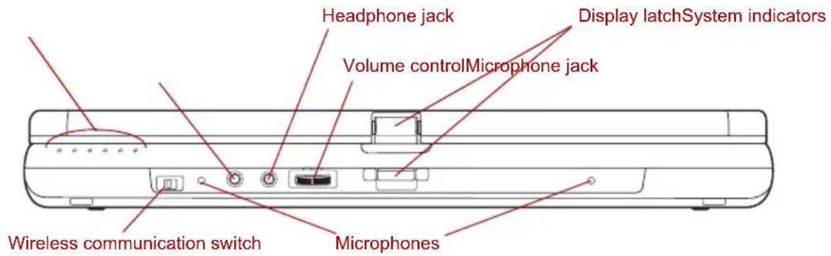
The following figure shows the computer's front with its LCD display panel in the closed position.
text_image
Headphone jack Display latchSystem indicators Volume controlMicrophone jack Wireless communication switch MicrophonesFront of the computer with LCD display panel closed
| System indicators These LEDs let you monitor the status of various computer functions. Details are given in the System indicatorssection. | ||
| Off On | Wireless communication switch | Slide this switch to the left to turn off Wireless LAN and Bluetooth functions. Slide it to the right to turn on the functions. |

■Turn WiFi and Bluetooth functionalities off when near a person who may have a cardiac pacemaker implant or other medical electric device. Radio waves may affect pacemaker or medical device operation, possibly resulting in serious injury. Follow the instruction of your medical device when using any WiFi or Bluetooth functionality.
■ Always turn off WiFi or Bluetooth functionality if the PC is near automatic control equipment or appliances such as automatic doors or fire detectors. Radio waves can cause malfunction of such equipment, possibly resulting in serious injury.
Do not use the WiFi or Bluetooth functionalities near a microwave oven or in areas subject to radio interference or magnetic fields. Interference from a microwave oven or other source can disrupt WiFi or Bluetooth operation.

Microphones The built-in microphones let you record sound into your applications. Refer to the Sound System section in Chapter 4, Operating Basics.
Microphone jack A 3.5 mm mini microphone jack enables connection of a three-conductor mini jack for monaural microphone input.
Headphone jack A 3.5 mm mini headphone jack enables connection of stereo headphones.
Volume control Use this dial to adjust the volume of the stereo speakers and the stereo headphones.
Display latch This latch secures the LCD panel in its closed position. Push the latch to open the display.
Left side
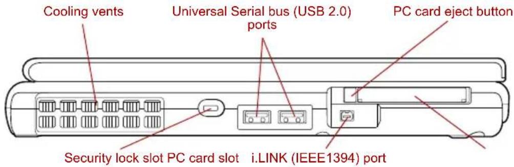
The following figure shows the computer's left side.
text_image
Cooling vents Universal Serial bus (USB 2.0) ports PC card eject button Security lock slot PC card slot i.LINK (IEEE1394) portThe left side of the computer
Cooling vents Cooling vents help CPU keep from overheating.

Do not block the cooling vents. Keep foreign metal objects, such as screws, staples and paper clips, out of the cooling vents. Foreign metal objects can create a short circuit, which can cause damage and fire, possibly resulting in serious injury.

Security lock slot A security cable attaches to this slot. The optional security cable anchors your computer to a desk or other large object to deter theft.
Universal Serial Bus (USB 2.0) ports Two Universal Serial Bus ports are on the left side. The ports comply with the USB 2.0 standard.

Keep foreign metal objects, such as screws, staples and paper clips, out of the USB connectors. Foreign metal objects can create a short circuit, which can cause damage and fire, possibly resulting in serious injury.

Operation of all functions of all USB devices has not been confirmed. Some functions might not execute properly.
PC card slot The PC card slot can accommodate a Type II card. The slot supports 16-bit PC cards and CardBus PC cards.
PC card eject button This button is used to remove a PC card from the PC card slot.

Keep foreign metal objects, such as screws, staples and paper clips, out of the PC Card slot. Foreign metal objects can create a short circuit, which can cause damage and fire, possibly resulting in serious injury.
i.LINK (IEEE1394) port
This port allows you to connect an external device, such as a digital video camera for high-speed data transfer.
Right side
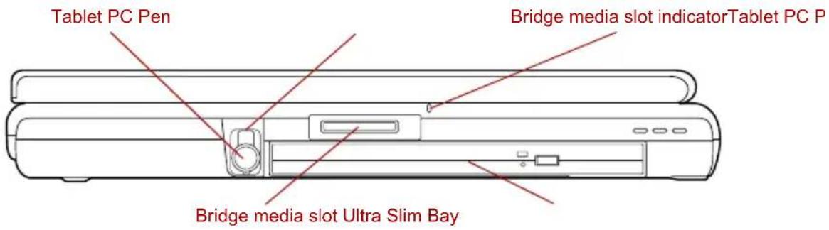
The following figure shows the computer's right side.
text_image
Tablet PC Pen Bridge media slot indicator Tablet PC P Bridge media slot Ultra Slim BayThe right side of the computer
Tablet PC Pen slot The Tablet PC Pen slot provides storage for the Tablet PC Pen.
| Tablet PC Pen The Tablet PC Pen is stored within the right side of the computer and enables direct data entry through the display screen. Refer to the Using the Tablet PC Pen and Reserve Pen section in Chapter 4, Operating Basics. |

| Bridge media slot This slot lets you insert an SD card, Memory Stick (Pro), xD picture card or SDIO card device. Refer to Chapter 8, Optional Devices . |

Keep foreign metal objects, such as screws, staples and paper clips, out of the Bridge Media Slot. Foreign metal objects can create a short circuit, which can cause damage and fire, possibly resulting in serious injury.
| Bridge media slot indicator | The Bridge media slot indicator glows green when the computer is accessing the device media installed in the Bridge media slot. |
| Ultra Slim Bay | A DVD-ROM / CD-R/RW drive, DVD Super Multi drive or Ultra Slim Bay Hard Disk Drive adaptor can be installed in the Ultra Slim Bay. |
Back side
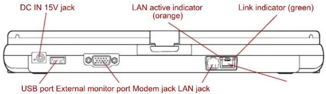
The following figure shows the computer's back side.
text_image
DC IN 15V jack LAN active indicator (orange) Link indicator (green) USB port External monitor port Modem jack LAN jackThe back side of the computer

natural_image
Three simple line drawings: a plug with a branch, a blank rounded rectangle, and a battery outline (no text or symbols)DC IN 15V jack The AC adaptor connects to this jack. Use only the model of AC adaptor that comes with the computer. Using the wrong adaptor can damage your computer.
Universal Serial Bus (USB 2.0) port The Universal Serial Bus port is on the back side. Refer to Right side section, for details. External monitor port This external monitor port lets you connect an external video display.
Modem jack The modem jack lets you use a modular cable to connect the modem directly to a telephone line.

■Connection to any communication line other than an analog phone line could cause a PC system failure.
■Connect the built-in modem only to ordinary analog phone lines.
■Never connect the built-in modem to a digital line (ISDN).
■Never connect the built-in modem to the digital connector on a public telephone or to a digital private branch exchange (PBX).
■Never connect the built-in modem to a key telephone system for residences or offices.
■Never operate your PC on AC power during a thunderstorm. If you see lightning or hear thunder, immediately turn off the PC. An electric surge caused by the storm, may result in a system failure, loss of data or hardware damage.
LAN jack This jack lets you connect to a LAN. The adaptor has built-in support for Ethernet LAN (10 megabits per second, 10BASE-T), Fast Ethernet LAN (100 megabits per second, 100BASE-TX) and Gigabit Ethernet LAN (1000 megabits per second, 1000BASE-T). The LAN has two indicators. Refer to Chapter 4, Operating Basics, for details.

Do not connect any cable other than a LAN cable to the LAN jack. It could cause damage or malfunction.
Do not connect the LAN cable to a power supply. It could cause damage or malfunction.
| Link indicator (green) | This indicator glows green when the computer is connected to a LAN and the LAN is functioning properly. |
| LAN active indicator (orange) | This indicator glows orange when data is being exchanged between the computer and the LAN. |
Underside
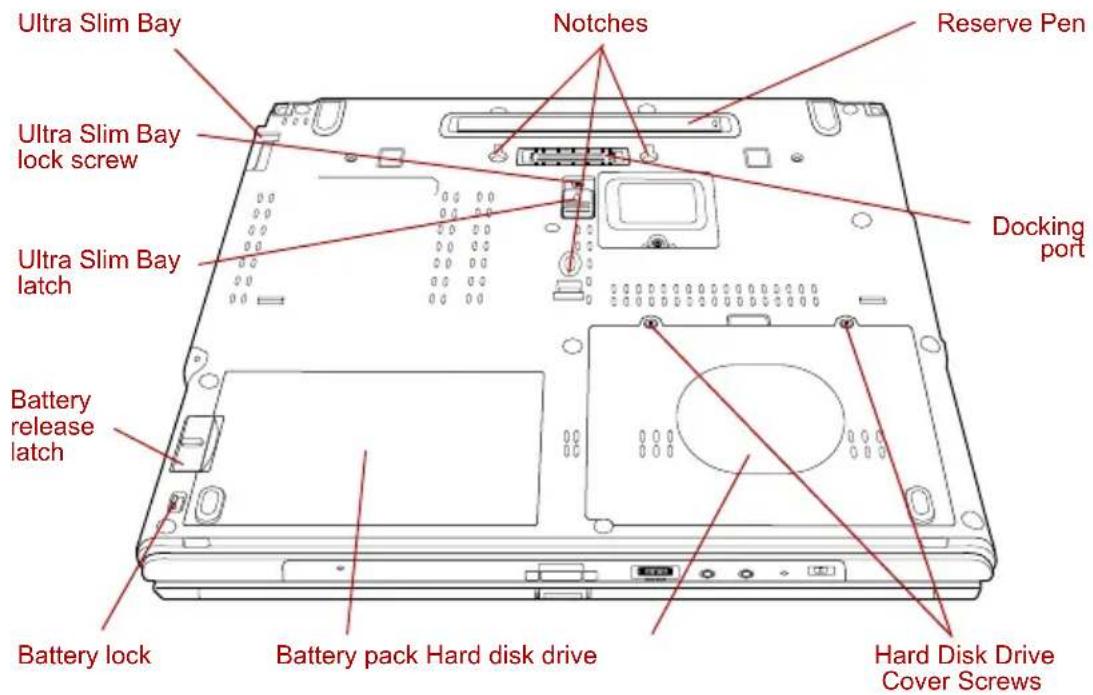
The following figure shows the underside of the computer. Make sure the display is closed before turning over your computer.
text_image
Ultra Slim Bay Notches Reserve Pen Ultra Slim Bay lock screw Ultra Slim Bay latch Docking port Battery release latch Battery lock Battery pack Hard disk drive Hard Disk Drive Cover ScrewsThe underside of the computer



Ultra Slim Bay See the Right side section in this chapter for details.
Ultra Slim Bay latch Slide the latch to release or secure the Ultra Slim Bay ejector.
Be sure to lock the Ultra Slim Bay latch before you transport or carry the computer.
Notches Notches on the computer engage hooks on the TOSHIBA Express Port Replicator to ensure a secure connection.
Reserve Pen The Reserve Pen is contained in the recess on the underside of the computer and enables data entry directly through display screen in addition to the main Tablet PC Pen. Refer to the Using the Tablet PC Pen and Reserve Pen section in Chapter 4, Operating Basics.

Hard Disk Drive Two screws secure the hard disk drive cover. Cover Screws
Hard disk drive This area contains the hard disk drive pack which can be removed and reinstalled if required. For more information on how to remove or reinstall the HDD Kit (Serial-ATA), refer to the section in Chapter 8, Optional Devices.
Battery pack The battery pack powers the computer when the AC adaptor is not connected. For detailed information on the battery pack, refer to Chapter 6, Power and Power-Up Modes.
Battery lock Slide the battery lock to release the battery pack for removal.
Battery release latch Slide and hold this latch to release the battery pack for removal. For detailed information on removing the battery pack, refer to Chapter 6, Power and Power-Up Modes.


Ultra Slim Bay lock screw One screw secures the Ultra Slim Bay latch.
Docking port This port enables connection of an optional TOSHIBA Express Port Replicator and a Slice Expansion Battery described in Chapter 8, Optional Devices.

Keep foreign objects out of the docking port. A pin or similar object can damage the computer's circuitry. A plastic shutter protects the connector.
Front with the display open
This section shows the computer with the LCD display panel open. Refer to the appropriate illustration for details. To open the display, push the display latch on the front of the LCD display panel and lift up. Position the LCD display panel at a comfortable viewing angle.
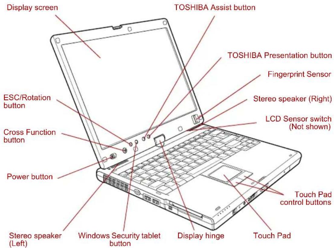
text_image
Display screen TOSHIBA Assist button TOSHIBA Presentation button Fingerprint Sensor Stereo speaker (Right) ESC/Rotation button LCD Sensor switch (Not shown) Cross Function button Power button Touch Pad control buttons Stereo speaker (Left) Windows Security tablet button Display hinge Touch PadThe front of the computer with the LCD panel open
Display hinge The display hinge holds the LCD display panel at easy-to-view angles.
| Display screen | The LCD screen displays high-contrast text and graphics. The available resolution depends on the model. With XGA, you can change the resolution between 800 × 600 and 1024 × 768 pixels. With SXGA+, between 800 × 600 and 1400 × 1050 pixels. Refer to Display Controller and Modes section in Appendix B.When the computer operates on the AC adaptor the LCD screen's image will be somewhat brighter than when it operates on battery power. The lower brightness level is intended to save battery power. | |
| Stereo speakers The speakers emit sound generated by your software as well as audio alarms, such as low battery condition, generated by the system. | ||
| Touch Pad A Touch Pad located in the center of the palm rest is used to control the on-screen pointer.Refer to the Using the Touch Pad section in Chapter 4, Operating Basics. | ||
| Touch Pad control buttons | Control buttons below the Touch Pad let you select menu items or manipulate text and graphics designated by the on-screen pointer. | |
| Power button Slide the power button to turn the computer's power on and off. | ||
 | Cross Function button | This button functions the same as the Enter key when tapped, or shows the menu screen when pressed for more than a second. |
 | ||
 | ESC/Rotation button This button functions the same as the ESC key when tapped, or changes the orientation of the screen when pressed for more than a second. | |
 | Windows Security tablet button | This button functions the same as the Ctrl + Alt + Del keys to show Windows Task Manager. |
 | TOSHIBA Assist button | Press this button to launch the TOSHIBA Assist utility (default) or some other predefined application.When the computer is switched off, or is in standby or hibernation mode, press this button to start the computer and launch the assigned application.You can specify the function of the TOSHIBA Assist button in the TOSHIBA Controls properties. |

TOSHIBA Presentation button
Press this button to display the same image on both internal and external monitors, or to use multi-monitor display (Windows XP Only).
The default setting is "Presentation (Same Image 1024 × 768)" - this means the same image will be displayed on both internal and external monitors with a resolution of 1024 × 768 pixels.
"When using the "Presentation (Different Image)" setting, you can use the internal and external monitors in wide screen mode (Windows XP only).
Pressing this button again changes to single display mode on the internal monitor only.
You can specify the function of the TOSHIBA Presentation button in the TOSHIBA Controls properties.
Fingerprint Sensor
Just by swiping the finger against the fingerprint sensor, the following functions will be enabled:
■ Logon to Windows and access a security-enabled homepage through IE (Internet Explorer).
■ Files and folders can be encrypted/decrypted and third party access to them prevented.
■ Disable the password-protected screen-saver when returning from power-saving (standby) mode.
■ Power-on Security and Single Sign-on feature.
■ Authentication of the User Password and Hard Disk Drive Password when booting up the computer.
LCD Sensor switch
This switch senses when the computer's LCD display panel is closed or opened and activates the Panel Power Off/On feature. When you close the LCD display panel the computer enters Hibernation Mode and shuts down. When you open the computer's LCD display panel the computer starts in Hibernation Mode. Use the TOSHIBA Power Saver Utility to enable or disable this feature. The default is "enabled".
Refer to the TOSHIBA Power Saver Utility and Panel Power Off/On items in Chapter 1, Special features, for details on settings.

Do not put a magnetic object close to the switch. The computer will automatically enter Hibernation Mode and shut down even if the Panel Power Off feature is disabled.
System indicators
LEDs beneath icons, light when various computer operations are in progress.
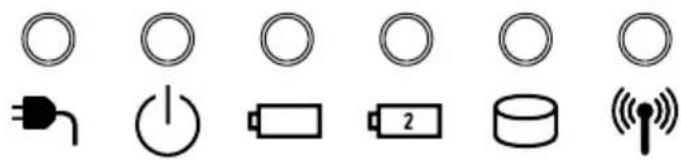
natural_image
Pure electrical circuit symbols without any text or labelsSystem indicators


DC IN
The DC IN indicator glows green when DC power is supplied from the AC power adaptor. If the adaptor's output voltage is abnormal or if the power supply malfunctions, this indicator flashes orange.
Power
The Power indicator glows green when the computer is on. If you select Standby from the Shut Down Windows menu, this indicator flashing (one second on, two seconds off) while the computer shuts down.
Battery
The Battery indicator shows the condition of the battery's charge: Green indicates full charge, orange indicates battery charging and flashing orange indicates a low battery charge. Refer to Chapter 6, Power and Power-Up Modes.
Secondary battery
The Secondary battery indicator shows the condition of the charge of a Slice Expansion Battery. Green means fully charged and orange means being charged. Refer to Chapter 6, Power and Power-Up Modes.
HDD The HDD indicator
glows green when the computer is accessing the built-in or Ultra Slim Bay hard disk drive.
Wireless communication
The Wireless communication indicator glows when the Bluetooth and wireless LAN functions are turned on.
Keyboard indicators
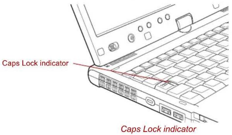
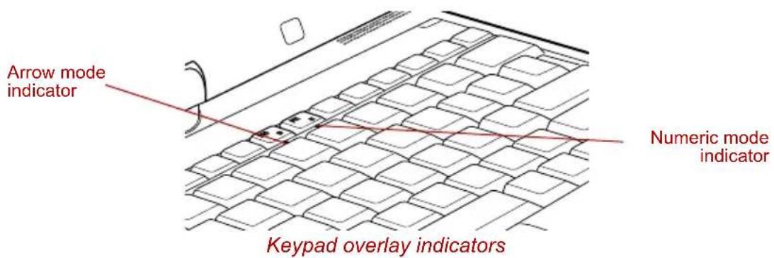
The figures below show the positions of the keypad overlay indicators and the Caps Lock indicator.
When the Arrow mode indicator glows the keypad overlay lets you control the cursor.
When the Numeric mode indicator glows the keypad overlay lets you enter numbers.
When the Caps Lock indicator glows the keyboard is in all-caps mode.
text_image
Caps Lock indicator Caps Lock indicatorCaps Lock This indicator glows green when the alphabet keys are locked in uppercase.
text_image
Arrow mode indicator Numeric mode indicator Keypad overlay indicators
Arrow mode
When the Arrow mode indicator lights green, you can use the keypad overlay (gray labeled keys) as cursor keys. Refer to the Keypad overlay section in Chapter 5, The Keyboard.
Numeric mode You can use the keypad overlay (gray labeled keys) for numeric input when the Numeric mode indicator lights green. Refer to the Keypad overlay section in Chapter 5, The Keyboard.
USB floppy disk drive (optional)
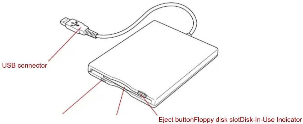
The USB floppy disk drive accommodates 1.44-megabyte or 720-kilobyte floppy disks and connects to the USB port.
text_image
USB connector Eject buttonFloppy disk slotDisk-In-Use IndicatorUSB floppy disk drive
USB connector Insert this connector into one of the USB ports of your computer.
Disk-In-Use Indicator This indicator lights when the floppy disk is being accessed.
Floppy disk slot Insert a floppy disk in this slot.
Eject button When a floppy disk is fully seated in the drive, the eject button pops out. To remove a floppy disk, push in the eject button and the floppy disk pops out partially for removal.

Check the Disk-In-Use indicator when you use the USB floppy disk drive. Do not press the eject button or turn off the computer while the light is glowing. Doing so could destroy data and damage the floppy disk or the drive.

The USB floppy disk drive should be placed on a flat, horizontal surface. Do not set the drive on an incline greater than 20° while it is operating.
■Do not set anything on top of the floppy disk drive.
Optical media drives
The computer is installed with either a DVD-ROM / CD-R/RW or a DVD Super Multi drive. An ATAPI interface controller is used for CD/DVD-ROM operation. When the computer is accessing a CD/DVD, an indicator on the drive glows.
For information on loading and unloading discs refer to the Using optical media drives section in Chapter 4, Operating Basics.
Region codes for DVD drives and media
DVD-ROM / CD-R/RW, DVD Super Multi drives and their associated media are manufactured according to the specifications of six marketing regions. When you purchase DVD-Video, make sure it matches your drive, otherwise it will not play properly.
Code Region
1 Canada, United States
2 Japan, Europe, South Africa, Middle East
3 Southeast Asia, East Asia
4 Australia, New Zealand, Pacific Islands, Central America, South America, Caribbean
5 Russia, Indian Subcontinent, Africa, North Korea, Mongolia
6 China
Writable discs
This section describes the types of writable CD/DVD discs. Check the specifications of your drive to see the types of discs it can write. Use RecordNow! to write compact discs. Refer to Chapter 4, Operating Basics.
CDs
■CD-R discs can be written only once. The recorded data cannot be erased or changed.
■CD-RW discs including multi speed CD-RW discs, high-speed CD-RW discs and ultra-speed CD-RW discs can be recorded more than once.
DVDs
■DVD-R and DVD+R discs can be written only once. The recorded data cannot be erased or changed.
■DVD-RW, DVD+RW and DVD-RAM discs can be recorded more than once.
Formats
The drives support the following formats:
CD-ROM
DVD -Video
DVD-ROM
CD-Text
CD-DA
■CD-ROM Mode 1, Mode 2
■Photo CD™ (single/multi-session)
■Enhanced CD (CD-EXTRA)
■CD-ROM XA Mode 2 (Form1, Form2)
■Addressing Method 2
DVD-ROM / CD-R/RW drive
The full-size DVD-ROM / CD-R/RW drive module lets you record data to rewritable CDs as well as run either 12 cm (4.72") or 8 cm (3.15") CD/DVDs without using an adaptor.

The read speed is slower at the center of a disc and faster at the outer edge.
DVD read 8 speed (maximum)
CD read 24 speed (maximum)
CD-R write 24 speed (maximum)
CD-RW write 24 speed (maximum, Ultra-speed media)
DVD Super Multi drive
The full-size DVD Super Multi drive module lets you record data to rewritable CDs as well as run either 12 cm (4.72") or 8 cm (3.15") CD/DVDs without using an adaptor.

The read speed is slower at the center of a disc and faster at the outer edge.
DVD read 8 speed (maximum)
DVD-R write 2 speed (maximum)
DVD-RW write 2 speed (maximum)
DVD+R write 2.4 speed (maximum)
DVD+RW write 2.4 speed (maximum)
DVD-RAM write 2 speed (maximum)
CD read 24 speed (maximum)
CD-R write 24 speed (maximum)
CD-RW write 10 speed (maximum, Ultra-speed media)
DVD Super Multi drive Double Layer
The full-size DVD Super Multi drive module lets you record data to rewritable CD/DVDs as well as run either 12 cm (4.72") or 8cm (3.15") CD/DVDs without using an adaptor.

The read speed is slower at the center of a disc and faster at the outer edge.
DVD read 8 speed (maximum)
DVD-R write 8 speed (maximum)
DVD-R DL write 2 speed (maximum)
DVD-RW write 4 speed (maximum)
DVD+R write 8 speed (maximum)
DVD+R DL write 2.4 speed (maximum)
DVD+RW write 4 speed (maximum)
DVD-RAM write 3 speed (maximum)
CD read 24 speed (maximum)
CD-R write 24 speed (maximum)
CD-RW write 16 speed (maximum, Ultra-speed media)
AC adaptor
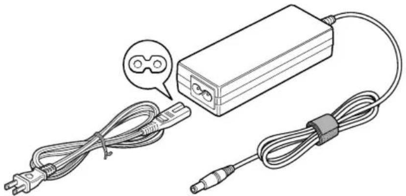
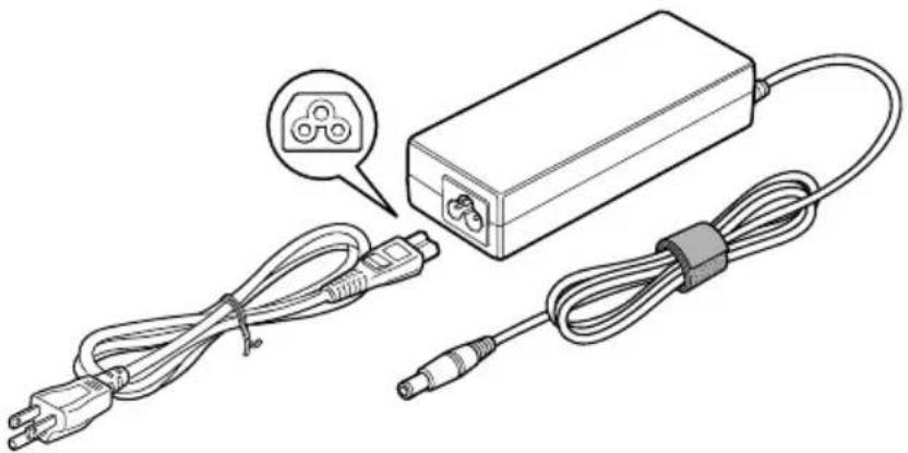
The AC adaptor can automatically adjust to any voltage ranging from 100 to 240 volts and to a frequency of either 50 or 60 hertz, enabling you to use this computer in almost any country/region. The adaptor converts AC power to DC power and reduces the voltage supplied to this computer.
To recharge the battery, simply connect the AC adaptor to a power source and the computer. Refer to Chapter 6, Power and Power-Up Modes for details.
natural_image
Line drawing of a battery pack connected to two cables, one with a speech bubble and the other with a connector (no text or symbols present)The AC adaptor (2-pin plug)
natural_image
Illustration of a power adapter connected to two cables, one with a plug icon and the other with a cable (no text or symbols)The AC adaptor (3-pin plug)

The Universal AC Adaptor and power cord bundled with this product may differ depending on the product model. Depending on the model, a 2-pin plug or 3-pin plug set of the above may be bundled.
■ Do not use a 3-pin to 2-pin conversion plug.
The supplied power cord conforms to safety rules and regulations in the region the product is bought and should not be used outside this region. For use in other regions, please buy power cords that conform to safety rules and regulations in the particular region.

Always use the Toshiba AC adaptor that was provided with your PC and the Toshiba Battery Charger (that may have been provided with your PC), or use Toshiba recommended alternate models to avoid any risk of fire or other damage to the PC. Use of an incompatible AC adaptor or Battery Charger could cause fire or damage to the PC possibly resulting in serious injury.
Chapter 3
Getting Started
This chapter provides basic information to get you started using your computer. It covers the following topics:
■Setting up your work space - for your health and safety

Be sure also to read Instruction Manual for Safety & Comfort. This guide, which is included with the computer, explains product liability.
■Connecting the AC adaptor
■ Opening the display
■Turning on the power
■Starting up for the first time
■Turning off the power
■Restarting the computer
■Restoring the preinstalled software
All users should be sure to read the section Starting up for the first time.
Setting up your work space
Establishing a comfortable work site is important for you and your computer. A poor work environment or stressful work habits can result in discomfort or serious injury from repetitive strain to your hands, wrists or other joints. Proper ambient conditions should also be maintained for the computer's operation. This section discusses the following topics:
■General conditions
■Placement of the computer
■Seating and posture
Lighting
■Work habits
General conditions
In general, if you are comfortable, so is your computer, but read the following to make sure your work site provides a proper environment.
■Select a work area that has:
■ a well-designed and functioning ventilation system that does not forcefully direct air on you
good air circulation
■a comfortable ambient temperature and relative humidity.
■Never place your PC where it will be exposed to excess heat, such as in direct sunlight, an unventilated vehicle or near a heater. This may result in a system failure, malfunction, loss of data or damage to the PC.
■Never place your PC in a location where it will be exposed to extremely low temperatures. This may result in a system failure, malfunction or loss of data.
■Never subject your PC to sudden temperature variations. This may result in condensation, causing a system failure, malfunction or loss of data.
■Do not expose your PC to dusty environments. If dust gets inside the PC, it could cause a system failure, malfunction or loss of data. If dust contaminates the PC, do not turn on the power. Take it to an authorized Toshiba service provider before you use it.
■ Never place your PC near an object that generates a magnetic field, such as a speaker or TV. Do not wear magnetic bracelets while using your PC. Exposure to magnetic fields can cause system failure, malfunction or loss of data.
■Never place a heavy object on the PC and be careful not to drop a heavy object onto the PC. It could damage the PC or cause system failure.
■Never use benzene, thinner or other chemicals when cleaning the PC, AC adaptor, or storage device. The use of benzene, thinner or other chemicals may result in deterioration, deformation or discoloration of those items and the loss of data.
■Make sure the AC power cord connects to an outlet that is close to the computer and easily accessible.
■The temperature should be 5 to 35 degrees Centigrade (41 to 95 degrees Fahrenheit) and the relative humidity should be 20 to 80 percent.
- Keep the computer free of dust, moisture, and exposure to direct sunlight.
■Some parts of the computer, including data storage media, can be damaged by magnets. Do not place the computer near magnetic objects or bring magnetic objects close to the computer. Be careful of objects, such as stereo speakers, that produce strong magnetic fields during operation. Also, be careful with metal objects, such as bracelets, which can be inadvertently magnetized.
- Do not operate the computer in close proximity to a mobile phone.
Leave ample ventilation room for the fan. Do not block the vents.
If the PC interferes with radio equipment, turn the PC power off immediately. Such interference could cause equipment malfunction.
■ Never place your PC on a shaky table, uneven, tilted surface or other unstable location. Your PC may fall, causing damage to the PC or possibly injury.
■Never leave the power to your PC on continuously for more than 24 hours. Turn the power off when this product is not in use.
■ Always avoid abrupt changes of temperature or humidity.
■Never place close to heat radiating appliances such as a heater.
■Never place close to corrosive chemicals.
■Never place close to magnetic field radiating appliances such as a stereo speaker.
■Always place this product on a flat surface.
■ Provide a sufficient space behind the PC to allow easy adjustment of the display panel.
■Always provide sufficient space around the PC to ensure adequate ventilation.
■Always provide sufficient space for operating a mouse and other peripheral devices.
Placement of the computer
Position the computer and peripheral devices to provide comfort and safety.
■Position your LCD display panel or place your monitor in an appropriate position to help reduce awkward postures and overhead glare. For example:
■ Position LCD directly in front of you and at a comfortable distance away.
■ Position LCD so the top of the screen is at or slightly below eye level. A display screen that is too high or too low can cause awkward postures and possibly fatigue muscles that support the head.
■Rest your eyes periodically by focusing on objects that are farther away.
If you use a paper holder, set it at about the same height and distance as the computer.
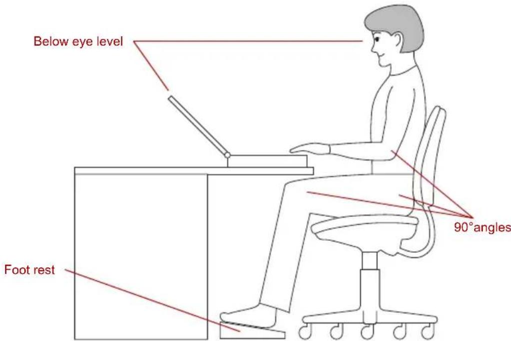
Seating and posture
Maintain a comfortable working posture when using your PC where your body joints are naturally aligned to reduce stress on different parts of your body. Consider the following:
text_image
Below eye level Foot rest 90° anglesPosture and positioning of the computer
- Keep hands, wrists, and forearms straight, in-line and roughly parallel to the floor.
- Keep head level, or bent slightly forward, forward facing, and balanced. Generally the head is in-line with the torso.
- Keep shoulders relaxed and let upper arms hang normally at the side of the body.
- Keep elbows in close to the body and bent.
- Keep feet fully supported by floor or foot rest.
- Keep back fully supported with appropriate lumbar support when sitting vertical or leaning back slightly.
- Keep thighs and hips supported by a well-padded seat cushion and generally parallel to the floor.
- Keep knees about the same height as the hips with the feet slightly forward.
Lighting
Select the right level of illumination and place your PC appropriately to minimize glare from overhead lights, desk lamps and windows. Glare on the LCD or monitor may cause eye strain, eye fatigue or headaches.
Consider the following suggestions regarding lighting your work environment:
■Position the PC so that the light source does not shine or reflect directly onto the display or shine or reflect directly into the eyes of the user.
■Shield the PC from direct light by using tinted windows or by installing blinds or a screen.
■Use soft, indirect lighting.
■ Adjust the display panel to provide maximum visibility.
Work habits
A key to avoiding discomfort or injury from repetitive strain is to vary your activities. If possible, schedule a variety of tasks into your workday. If you must spend long periods at the computer, finding ways to break up the routine can reduce stress and improve your efficiency.
■Sit in a relaxed posture. Good positioning of your chair and equipment as described earlier can reduce tension in your shoulders or neck and ease back strain.
■Vary your posture frequently.
■Occasionally stand up and stretch or exercise briefly.
■Exercise and stretch your wrists and hands a number of times during the day.
Frequently, look away from the computer and focus your eyes on a distant object for several seconds, for example 30 seconds every 15 minutes.
■Take frequent short breaks instead of one or two long breaks, for example, two or three minutes every half hour.
When you use a PC, rest your eyes periodically and relax or stretch your muscles to avoid strain. If you experience discomfort while operating the PC, stop immediately and rest. Continuous operation for long periods without adequate rest may cause pain in the arms, wrists, hands, back, neck or other parts of the body. If pain persists despite rest, consult your doctor.
A number of books are available on ergonomics and repetitive strain injury or repetitive stress syndrome. For more information on these topics or for pointers on exercises for such stress points as hands and wrists, please check with your library or book vendor. Also refer to the computer's Instruction Manual for Safety & Comfort.
Strategic Rest Breaks
Take short, strategically spaced rest breaks to avoid eye strain and body discomforts.
Other Things to Note
■Never turn off the power while an application is running. Doing so could cause loss of data.
■Use a virus-check program and make sure it is updated regularly.
■Never turn off the power, disconnect an external storage device or remove storage media during data read/write. Doing so can cause data loss.
■Never format storage media without checking its content. Formatting destroys all stored data.
It is a good idea to periodically back up the internal hard disk or other main storage device to external media. General storage media is not durable or stable over long periods of time and under certain conditions may result in data loss.
■Before you install a device or application, save any data in memory to the hard disk drive or other storage media. Failure to do so may result in the loss of data.
Operating the computer in Tablet mode

Change to "The TOSHIBA PORTÉGÉ M400 computer can be used in two ways, as an ordinary laptop PC and as a Tablet PC. You can use the computer as Tablet PC, operated with the supplied Tablet PC Pen, by turning the LCD display panel through 180 degrees and closing it. This manual calls the use as an ordinary laptop PC 'laptop mode', and the use as a Tablet PC 'Tablet mode'. Refer to Changing to the Tablet mode section in Chapter 4, Operating Basics for details on changing the mode.
When operating the computer in tablet mode, follow the instructions below.
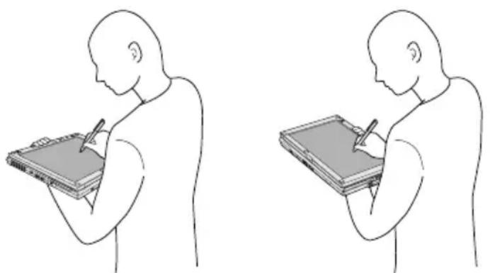
natural_image
Two identical line drawings of a human figure in profile, showing hand-drawn sketches of writing or drawing (no text or symbols present)Operating the computer in tablet mode
- Hold the computer firmly on your forearm. Do not block the vent.
■Remove the AC adaptor from the computer when using it in tablet mode held in your forearm.
■Do not use the computer while walking or driving a car.
■Change to laptop mode and turn off the computer before carrying it. Do not carry the computer with power on or in stand by state. Do not carry the computer while the disk activity LED is glowing.
■Do not expose the computer to rapid temperature changes (such as would be the case if you brought the PC from a cold environment into a warm room). When rapid temperature changes are unavoidable, leave the computer for around two hours before turning it on to prevent the formation of condensation.
■Remove all external peripheral devices and their connection cables from the computer before carrying.
- Do not drop the computer or apply excessive impact to it. Do not leave the computer in a car or similar environment where it is exposed to direct sunlight.
- Do not put the computer in a bag when it is in tablet mode.
The display panel works as a touch sensitive digitizer screen. However, the outer edges of the screen may be less sensitive. Please keep the Tablet PC Pen inside the display area when you use it near the edges of the display panel. The position of the pen may not be recognized if you move the Tablet PC Pen too fast towards the outer edge. Please be sure to slide the Tablet PC Pen slowly in areas near the edges of the screen.
Use the Tablet PC Pen in the areas enclosed by the dotted line as shown in the following figure.
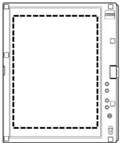
natural_image
Front view of a rectangular electronic device with dashed square frame and control buttons (no text or symbols)
natural_image
Front view of a computer monitor with dashed square outline and control buttons at bottom (no text or symbols)Use area of a Tablet PC Pen

Do not block the vent of the computer when holding it. If you continue to expose your skin to the hot air expelled from the vent for a long time, your skin might suffer low temperature injury.
Connecting the AC adaptor
Attach the AC adaptor when you need to charge the battery or you want to operate from AC power. It is also the fastest way to get started, because the battery pack will need to be charged before you can operate from battery power.
The AC adaptor can be connected to any power source supplying from 100 to 240 volts and 50 or 60 hertz. For details on using the AC adaptor to charge the battery pack, refer to Chapter 6, Power and Power-Up Modes.

Always use the Toshiba AC adaptor that was provided with your PC and the Toshiba Battery Charger (that may have been provided with your PC), or use Toshiba recommended alternate models to avoid any risk of fire or other damage to the PC. Use of an incompatible AC adaptor or Battery Charger could cause fire or damage to the PC possibly resulting in serious injury.
Use only the AC adaptor supplied with your computer or an equivalent adaptor that is compatible. Use of any incompatible adaptor could damage your computer. TOSHIBA assumes no liability for any damage caused by use of an incompatible adaptor.
■Never plug the AC adaptor or Battery Charger into a power source that does not correspond to both the voltage and the frequency specified on the regulatory label of the unit. Failure to do so could result in a fire or electric shock, possibly resulting in serious injury.
■Always use or purchase power cables that comply with the legal voltage and frequency specifications and requirements in the country of use. Failure to do so could result in a fire or electric shock, possibly resulting in serious injury.
The supplied power cord conforms to safety rules and regulations in the region the product is bought and should not be used outside this region. For use in other regions, please buy power cords that conform to safety rules and regulations in the particular region.
■Do not use a 3-pin to 2-pin conversion plug.
When you connect the AC adaptor to the computer, always follow the steps in the exact order as described in the User's Manual. Connecting the power cable to a live electrical outlet should be the last step otherwise the adaptor DC output plug could hold an electrical change and cause an electrical shock or minor bodily injury when touched. As a general safety precaution, avoid touching any metal parts.
■Never place an AC adaptor on a wooden surface, furniture, or any other surface that could be marred by exposure to heat since the AC adaptor's surface temperature increases during normal use.
■Always place the PC on a suitable heat-insulating material to prevent possible heat damage.
- Connect the power cord to the AC adaptor.
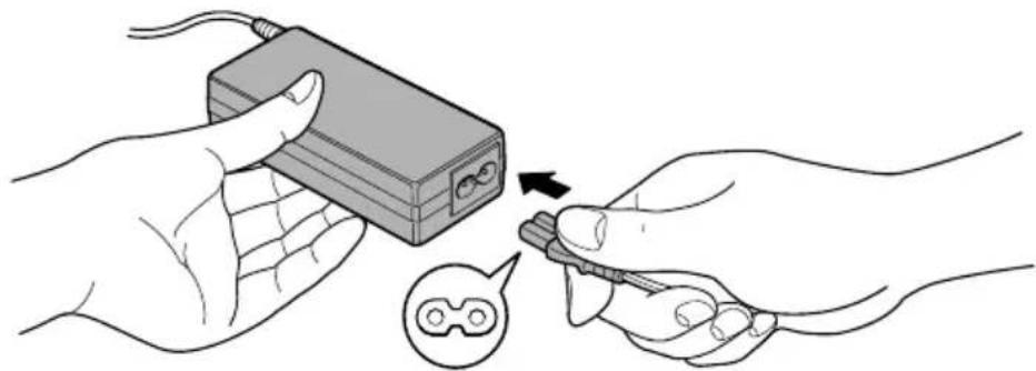
natural_image
Illustration of hands using a handheld device to adjust or install a device (no text or symbols visible)Connecting the power cord to the AC adaptor (2-pin plug)
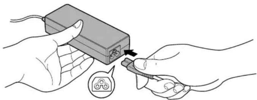
natural_image
Illustration of hands connecting a device to a connector with a magnified inset showing a connector (no text or symbols)Connecting the power cord to the AC adaptor (3-pin plug)

The Universal AC Adaptor and power cord bundled with this product may differ depending on the product model. Depending on the model, a 2-pin plug or 3-pin plug set of the above may be bundled.
- Connect the AC adaptor's DC output plug to the DC IN 15V jack on the back of the computer.
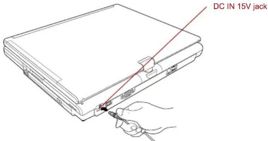
text_image
DC IN 15V jackConnecting the adaptor to the computer
- Plug the power cord into a live wall outlet. The Battery and DC IN indicators on the front of the computer should glow.
Opening the display
The computer's LCD display panel can be opened in a wide range of angles for optimal viewing.
- Push the display latch on the front of the computer to unlatch the display panel.
- While holding down the palm rest with one hand so that the main body is not raised, lift the panel slowly. Adjust the angle of the panel to provide optimal clarity.

Use reasonable care when opening and closing the LCD display panel. Opening it vigorously or slamming it shut could damage the computer.
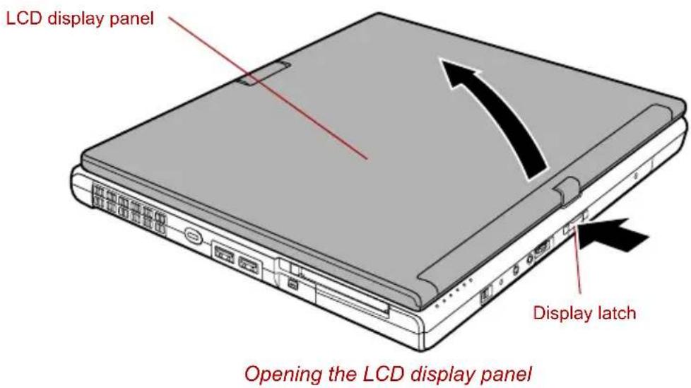
text_image
LCD display panel Display latch Opening the LCD display panelTurning on the power
This section describes how to turn on the power.
The Power button LED indicates the status. Refer to the Power indicators section in Chapter 6, Power and Power-Up Modes.

After you turn on the power for the first time, do not turn it off until you have set up the operating system. Refer to the section Starting up for the first time.
If the USB floppy disk drive is connected, make sure it is empty. If a floppy disk is in the drive, press the eject button and remove the floppy disk.
-
Open the computer's LCD display panel.
-
Slide and hold the computer's power button.
Power button
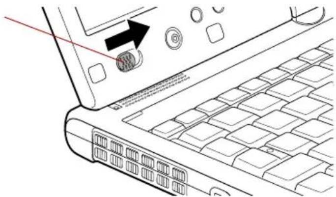
natural_image
Line drawing of a laptop keyboard with an arrow pointing to the screen (no text or symbols present)Turning on the power
Starting up for the first time
When you first turn on the power, the computer's initial screen is the Microsoft Windows XP Startup Screen Logo. Follow the on-screen directions for each screen. During setup, you can click the Back button to return to the previous screen.

Be sure to read the Windows End User License Agreement display carefully.
Turning off the power
The power can be turned off in one of the following modes: Shut down (Boot), Hibernation or Standby Mode.
Shut Down mode (Boot mode)
When you turn off the power in Shut Down mode no data is saved and the computer will boot to the operating system's main screen.
- If you have entered data, save it to the hard disk or to a storage media.
- Make sure all disk (disc) activity has stopped, then remove the CD/DVDs or floppy disk.

■Make sure the hard disk drive and Ultra Slim Bay module indicators are off. If you turn off the power while a disk (disc) is being accessed, you can lose data or damage the disk.
■ Never turn off the power while an application is running. Doing so could cause loss of data.
■Never turn off the power, disconnect an external storage device or remove storage media during data read/write. Doing so can cause data loss.
-
Click start then click Turn Off Computer. From the Turn Off Computer menu select Turn Off.
-
Turn off the power to any peripheral devices.

Do not turn the computer or devices back on immediately. Wait a moment to let all capacitors fully discharge.
Standby Mode
If you have to interrupt your work, you can turn off the power without exiting from your software. Data is maintained in the computer's main memory. When you turn on the power again, you can continue working right where you left off.

■When the AC adaptor is connected, the computer will go into Standby Mode according to the settings in the TOSHIBA Power Saver utility.
To restore operation from Standby Mode, slide the power button or press any key. The latter action only works on the internal keyboard if the Wake-up on Keyboard option is enabled in HW Setup.
If the computer automatically enters Standby Mode while a network application is active, the application might not be restored when the computer wakes up from Standby.
To prevent the computer from automatically entering Standby Mode, disable Standby in TOSHIBA Power Saver. That action, however, will nullify the computer's Energy Star compliance.

■Before entering Standby Mode, be sure to save your data.
Do not install or remove a memory module while the computer is in Standby Mode. The computer or the module could be damaged.
■Do not remove the battery pack while the computer is in Standby Mode (unless the computer is connected to an AC power source). Data in memory will be lost.
If you carry the computer on board an aircraft or into a hospital, be sure to shut down the computer in Hibernation Mode or in shutdown mode to avoid radio signal interference.
Benefits of standby
The standby feature provides the following benefits:
■Restores the previous working environment more rapidly than does hibernation.
■ Saves power by shutting down the system when the computer receives no input or hardware access for the duration set by the System Standby feature.
■You can use the panel power off feature.
Executing standby

You can also enable Standby by pressing Fn + F3. See Chapter 5, The Keyboard, for details.
You can enter Standby Mode in one of three ways:
- Click start, click Turn Off Computer and click Stand By.
- Close the computer's LCD display panel. This feature must be enabled. Refer to the Setup Actions tab in TOSHIBA Power Saver Utility located within the Control Panel application (open Performance and Maintenance and then open TOSHIBA Power Saver).
- Slide the power button. This feature must be enabled. Refer to the Setup Actions tab in TOSHIBA Power Saver Utility located within the Control Panel application (open Performance and Maintenance and then open TOSHIBA Power Saver).
When you turn the power back on, you can continue where you left when you shut down the computer.

■When the computer is shut down in Standby Mode, the power indicator will blink orange.
If you are operating the computer on battery power, you can lengthen the operating time by shutting down in Hibernation Mode. Standby Mode consumes more power.
Standby limitations
Standby will not function under the following conditions:
■Power is turned back on immediately after shutting down.
■Memory circuits are exposed to static electricity or electrical noise.
Hibernation Mode
The Hibernation Mode feature saves the contents of memory to the hard disk when the computer is turned off. The next time the computer is turned on, the previous state is restored. The Hibernation Mode feature does not save the status of any peripheral devices.

- Save your data. While entering Hibernation Mode, the computer saves the contents of memory to the hard disk drive. However, for safety sake, it is best to save your data manually.
■Data will be lost if you remove the battery or disconnect the AC adaptor before the save is completed. Wait for the HDD indicator to go out.
■Do not install or remove a memory module while the computer is in Hibernation Mode. Data will be lost.
Benefits of Hibernation Mode
The Hibernation Mode feature provides the following benefits:
■Saves data to the hard disk when the computer automatically shuts down because of a low battery.

For the computer to shut down in Hibernation Mode, this feature must be enabled in two places: the Hibernate tab in Power Options and Setup Actions tab in TOSHIBA Power Saver.
If you do not configure this feature, the computer will shut down in Standby Mode - if battery power becomes depleted, data saved in Standby Mode will be lost.
■You can return to your previous working environment immediately when you turn on the computer.
■ Saves power by shutting down the system when the computer receives no input or hardware access for the duration set by the System hibernate feature.
■You can use the panel power off feature.
Starting Hibernation Mode

You can also enable Hibernation Mode by pressing Fn + F4. Refer to Chapter 5, The Keyboard, for details.
To enter Hibernation Mode, follow the steps below.
- Click start.
- Select Turn Off Computer.
- Open the Turn Off Computer dialog box.
- Click Hibernate.
Automatic Hibernation
The computer will enter Hibernate mode automatically when you slide the power button or close the lid. First, however, make the appropriate settings according to the steps below.
- Click start and open the Control Panel.
- Open Performance and Maintenance and open Power Options.
- Select the Hibernate tab in the Power Options Properties, select the Enable hibernation check box and click the Apply button.
- Open TOSHIBA Power Saver.
- Select the Advanced tab.
- Enable the desired Hibernation settings for When I slide the power button and When I close the lid.
- Click the OK button.
Data save in Hibernation Mode
When you turn off the power in Hibernation Mode, the computer takes a moment to save current memory data to the hard disk. During this time, the HDD indicator will light.
After you turn off the computer, and the content of memory has been saved to the hard disk, turn off the power to any peripheral devices.

Do not turn the computer or devices back on immediately. Wait a moment to let all capacitors fully discharge.
Restarting the computer
Certain conditions require that you reset the system. For example, if:
■You change certain computer settings.
■An error occurs and the computer does not respond to your keyboard commands.
There are three ways to reset the computer system:
- Click start then click Turn off computer. From the Turn off computer menu select Restart.
- Press Ctrl + Alt + Del to display the Windows Task Manager, then select Shut Down and Restart.
- Slide the power button and hold it down for five seconds. Wait 10 to 15 seconds, then turn the power on again by sliding the power button.
Restoring your preinstalled software
If preinstalled files are damaged, use your Product Recovery DVD-ROM to restore them. To restore the operating system and all preinstalled software, follow the steps below.

When sound is muted by the Fn + Esc key, turn it on before starting the restore procedure. Refer to Chapter 5, The Keyboard, for details.

When you reinstall the Windows operating system, the hard disk will be reformatted and all data will be lost.
- Load the Recovery Media in the optional optical media drive and turn off the computer's power.
- Hold down the F12 key and turn on the power. When In Touch with Tomorrow TOSHIBA appears, release the F12 key.
- Use the left or right cursor key to select the CD-ROM icon in the display menu.
- Follow the on-screen instructions.
Restoring TOSHIBA utilities and drivers
If Windows is working properly, individual drivers or applications can be separately restored. The TOSHIBA Tools & Utilities folder (C:\TOOLSCD) contains drivers and applications, which are included with your computer system. If your system drivers or applications have become damaged in some way, you can reinstall most of the components from this folder.
Create a copy of this folder to an external media for more convenience.
Chapter 4
Operating Basics
This chapter describes the basic operations of your computer and precautions when using it, as well as the handling of CD/DVD.
Using the Touch Pad
To use the Touch Pad, simply touch and move your fingertip across it in the direction you want the on-screen pointer to go.
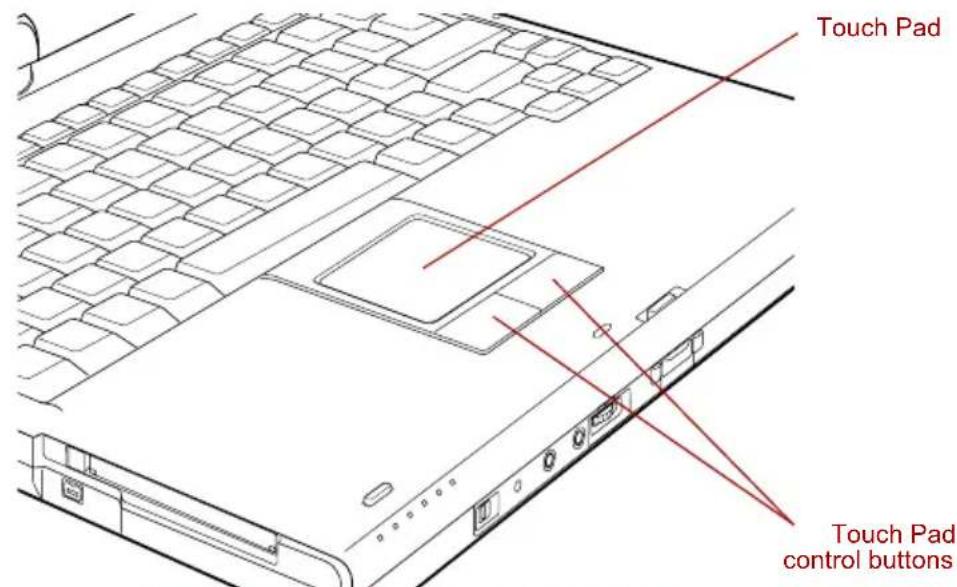
text_image
Touch Pad Touch Pad control buttonsTouch Pad and Touch Pad control buttons
Two buttons below the Touch Pad are used like the buttons on a mouse pointer. Press the left button to select a menu item or to manipulate text or graphics designated by the pointer. Press the right button to display a menu or other function depending on the software you are using.

You can also tap the Touch Pad to perform functions similar to those of the left button.
Click: Tap once
Double-click: Tap twice
Drag and drop: Tap to select the material you want to move. Leave your finger on the Touch Pad after the second tap and move the material.
Using the Tablet PC Pen and Reserve Pen
You can use the Tablet PC Pen to execute actions and enter data. Hold the Tablet PC Pen in a natural position and tap, press or trace on the screen lightly. Before you begin using your computer for the first time, you will need to calibrate the Tablet PC Pen.
Some computers in this series are equipped with a Reserve Pen.
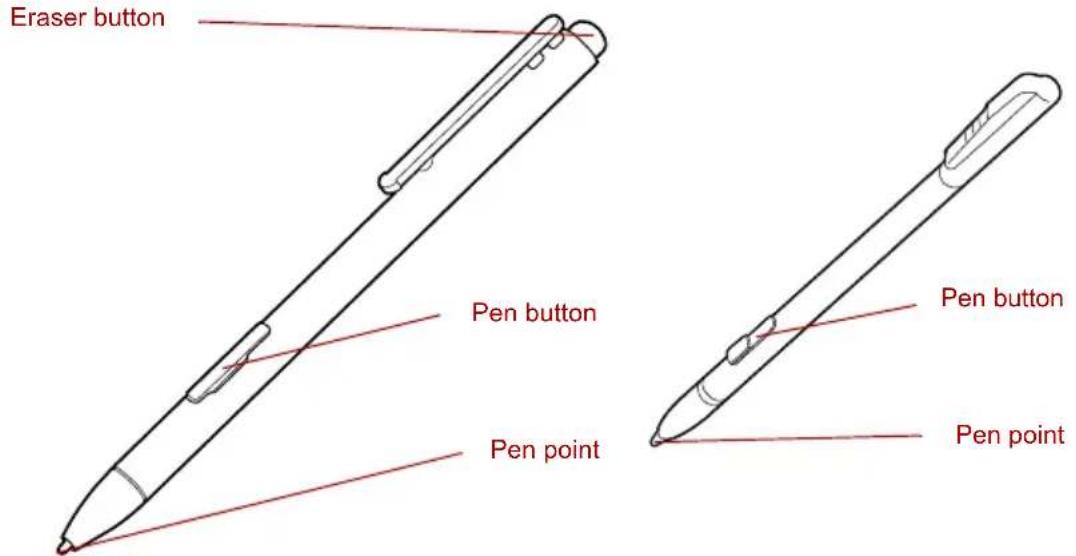
text_image
Eraser button Pen button Pen point Pen button Pen pointThe Tablet PC Pen (left) and Reserve Pen (right)
Eraser button You can use this button as an eraser when using a graphics software application. Text based software applications enable you to select and delete characters with a one-touch action.
Pen button Provides the same function as clicking the right Touch pad control button.
Pen point Provides the same function as clicking the left Touch pad control button.

Observe the following precautions on the handling of the Tablet PC Pen.
Do not tap or press the Tablet PC Pen forcefully against the display as this could damage the Tablet PC Pen and the screen itself.
■Avoid using or keeping the Tablet PC Pen in areas where the temperature can change rapidly or in places, such as a car, where the Tablet PC Pen is exposed to direct sunlight. Store the Tablet PC Pen without any pressure being applied to the buttons as this may cause a malfunction or characteristic deterioration.
The Tablet PC Pen is composed of precision parts. Do not drop the Tablet PC Pen. Strong impact causes a malfunction or characteristic deterioration.
Do not apply excessive force to the Tablet PC Pen point and the side switch. Excessive force applied to these parts causes short life or characteristic deterioration (Allowable force to pen point, Eraser button, Pen button: less than 1 kg, for less than 30 seconds).
■Avoid water entering the Tablet PC Pen or condensation forming within it as either condition will cause a malfunction.
■Do not disassemble the Tablet PC Pen. It causes maladjustment or short life.
Do not stain the Tablet PC Pen with cosmetics or chemicals as this will cause a deterioration in appearance. Use a glass wiping cloth or dry cloth to clean the Tablet PC Pen. Do not use volatile liquids such as alcohol, thinner or petroleum benzine to clean the Tablet PC Pen.
Do not apply excessive force to the Tablet PC Pen point as a bent or deformed pen point will cause a malfunction.
- Keep the small parts of the Tablet PC Pen, such as the pen point or the knob of the side switch, away from infants and small children to prevent them from swallowing them.
■Do not use a ball point pen instead of the Tablet PC Pen delivered with the product.
Do not use a broken pen tip. The lead cannot be replaced if it is worn (use the Reserve Pen only).

TOSHIBA is not liable for any problems arising on the products due to the use of the Tablet PC Pen in an environment where the above conditions are not satisfied or because of its use by unspecified number of users.
Removing the Tablet PC Pen
Remove the Tablet PC Pen as described below.
- Gently push the Tablet PC Pen towards the middle of the computer. The pen will then protrude slightly from the side.
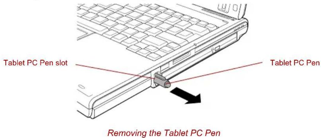
text_image
Tablet PC Pen slot Tablet PC Pen Removing the Tablet PC Pen- Pull the Tablet PC Pen to remove it from the Tablet PC Pen slot.
Inserting the Tablet PC Pen
The Tablet PC Pen is included in the accessory tray when purchased. Remove the Tablet PC Pen from the carton and install it to the computer as follows:
- The Tablet PC Pen and the Reserve Pen are different in shape.

The Tablet PC Pen and the Reserve Pen are different in shape. Do not insert the Reserve Pen into the Tablet PC Pen slot.
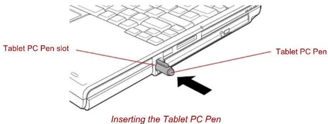
text_image
Tablet PC Pen slot Tablet PC Pen Inserting the Tablet PC PenPen actions
You can use the Tablet PC Pen to enter data, start programs, move objects and execute other actions.
Single tap
Lightly tap the tip of the Tablet PC Pen on an object and lift it immediately to execute an action. A single tap is similar to clicking the left touch pad control button.
Double tap
Lightly tap the tip of the Tablet PC Pen twice on an object and lift it immediately to execute an action. A double-tap is similar to double-clicking the left touch pad control button.
Press and hold
Touch the tip of the Tablet PC Pen to the display screen and hold it there to display a pop-up menu or other action. Press and hold is similar to clicking the right touch pad control button.
Drag
Touch the Tablet PC Pen to the screen. Without lifting the Tablet PC Pen, drag it across the screen to select text or objects.
Drag and drop
Touch the Tablet PC Pen to the screen to select an object. Without lifting the Tablet PC Pen, drag it across the screen. Lift the Tablet PC Pen to drop the object to a new location.
Replacing the pen tip
- To replace the pen tip, pinch the tip with a draw-out tool and pull it out.
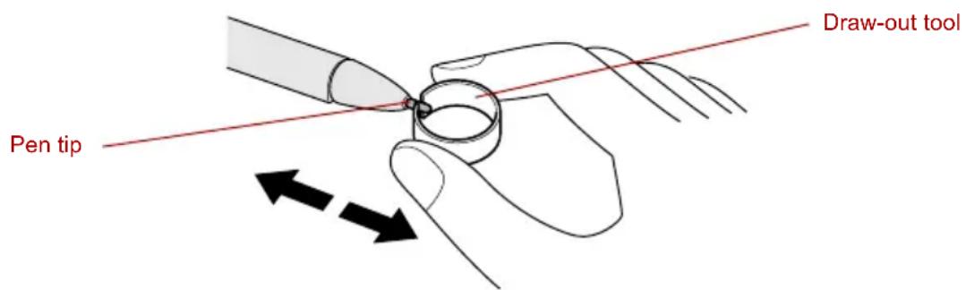
text_image
Pen tip Draw-out toolReplacing the pen tip
- Insert a new tip into the Tablet PC Pen, flat end first, and press it to seat it securely.

A short and worn pen point is difficult to pull out. Replace the pen point with a refill before it becomes too short to remove.
It is recommended that you keep another pen set as a spare. You can buy replacement pen sets from your TOSHIBA authorized dealer.

Do not continue to use a broken pen tip as this may result in scratching of the LCD display panel. When the pen tip breaks replace it with one of the refills delivered with the Tablet PC Pen. When these refills have run out, you can purchase a new pen set from a TOSHIBA authorized dealer.
Removing the Reserve Pen case
To remove the Reserve Pen case, follow the steps below.
- Save your work.
- Turn the computer's power off. Make sure the Power indicator is off.
- Remove all cables connected to the computer.
- Close the LCD display panel and turn the computer upside down.
- Slide and then lift out the Reserve Pen case.

Push lightly at the point shown by the arrow using an object with a thin tip.
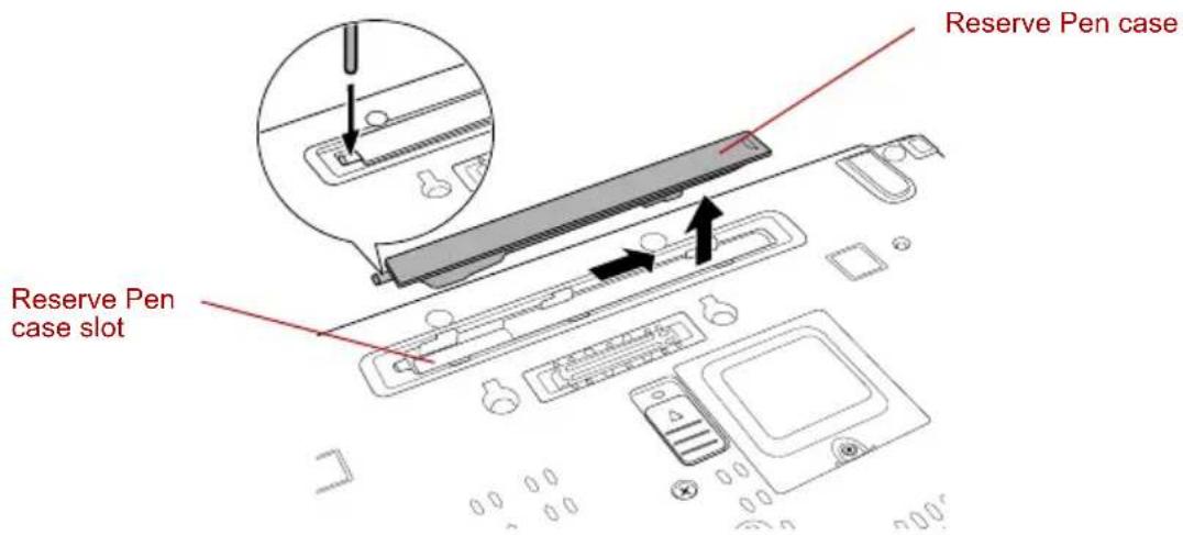
text_image
Reserve Pen case Reserve Pen case slotRemoving the Reserve Pen case
Inserting the Reserve Pen case
To insert the Reserve Pen case, follow the steps below.
- Insert the Reserve Pen case into the Reserve Pen case slot on the computer and slide it until it locks.
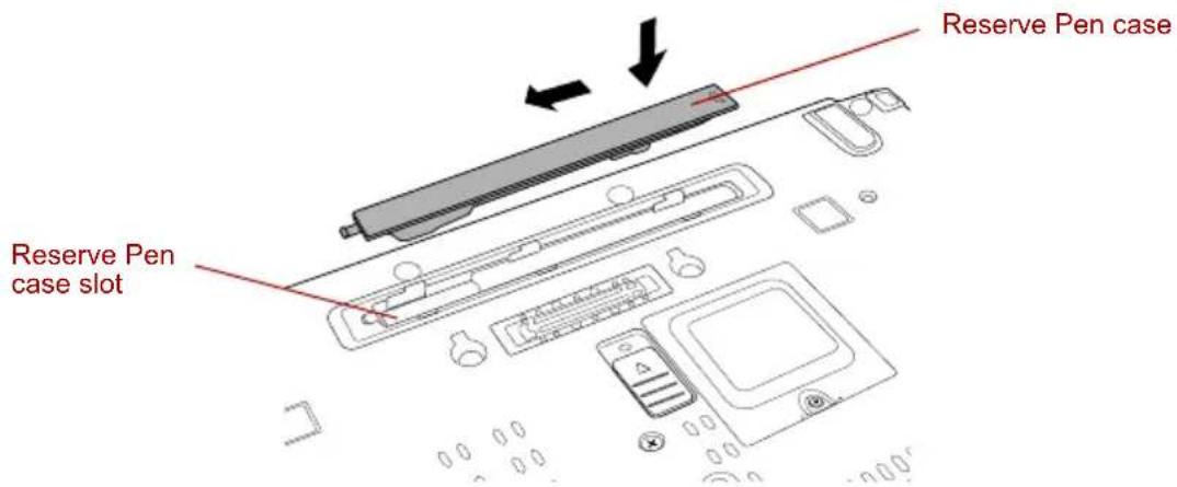
text_image
Reserve Pen case Reserve Pen case slotInserting the Reserve Pen case
Storing and Removing the Reserve Pen from the Reserve Pen case
Follow the procedures below to remove the Reserve Pen from the Reserve Pen case.
Removing the Reserve Pen from the Reserve Pen case
- Lift the Reserve Pen up from the Reserve Pen case by its end.
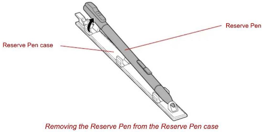
text_image
Reserve Pen Reserve Pen case Removing the Reserve Pen from the Reserve Pen caseStoring the Reserve Pen in the Reserve Pen case
- Insert the tip of the Reserve Pen into the Reserve Pen case holder and press down.
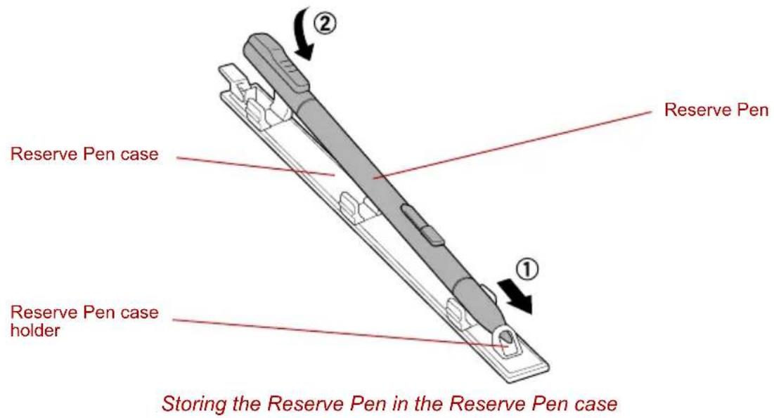
text_image
Reserve Pen Reserve Pen case Reserve Pen case holder Storing the Reserve Pen in the Reserve Pen caseChanging to the Tablet mode
To change from laptop mode to the Tablet mode, follow the instructions below.
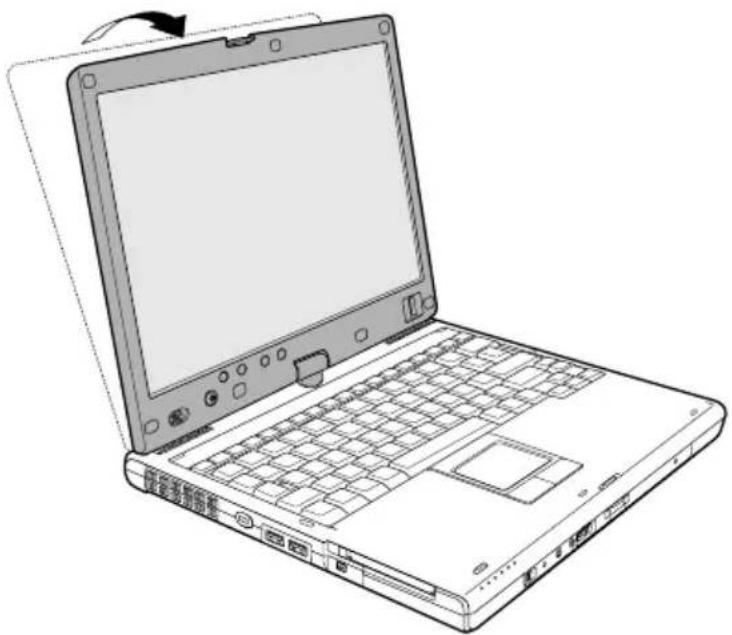
natural_image
Line drawing of a laptop computer with visible keyboard, front panel, and scrollpad (no text or symbols)Changing to the Tablet mode (1)

Place the computer on a stable, flat surface such as a desktop and rotate the LCD display panel slowly, holding the panel at its lower part. The LCD display panel is designed not to rotate more than 180 degrees. Rotating the LCD display panel more than 180 degrees with an excessive force will damage the panel and the computer.
■ To change from Laptop Mode to Tablet Mode you must rotate the display panel 180 degrees clockwise.
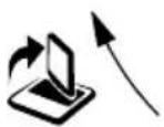
Tablet mode icon Turn the LCD display panel to the direction indicated by the Tablet mode icon.

To change from Tablet Mode to Laptop Mode you must rotate the display panel 180 degrees counter-clockwise.
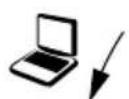
Laptop mode icon Turn the LCD display panel to the direction indicated by the laptop mode icon.
-
Open the LCD display panel to the upright position. Check that the angle of the keyboard and the LCD display panel is 90 degrees.
-
Rotate the LCD display panel clockwise slowly.
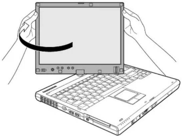
natural_image
Line drawing of hands holding a laptop with a scroll, next to an open keyboard (no text or symbols visible)Changing to the Tablet mode (2)

Do not apply excessive rotating force to the LCD display panel. It causes damage of the LCD display panel.
- Turn the display latch 180 degrees to its down position.
- Close the LCD display panel slowly with display surface facing upwards.
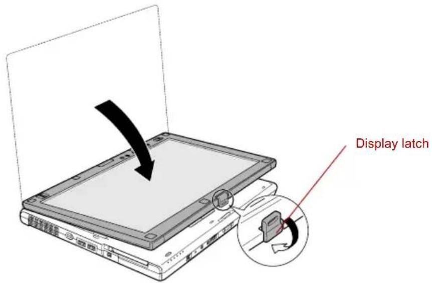
text_image
Display latchChanging to the Tablet mode (3)
-
Insert the display latch in the slit.
-
Press the LCD display panel downward softly.
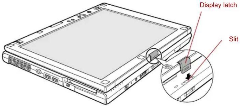
text_image
Display latch SlitChanging to the Tablet mode (4)
Changing the screen orientation
The orientation of the computer screen can be changed to one of the following four display modes:
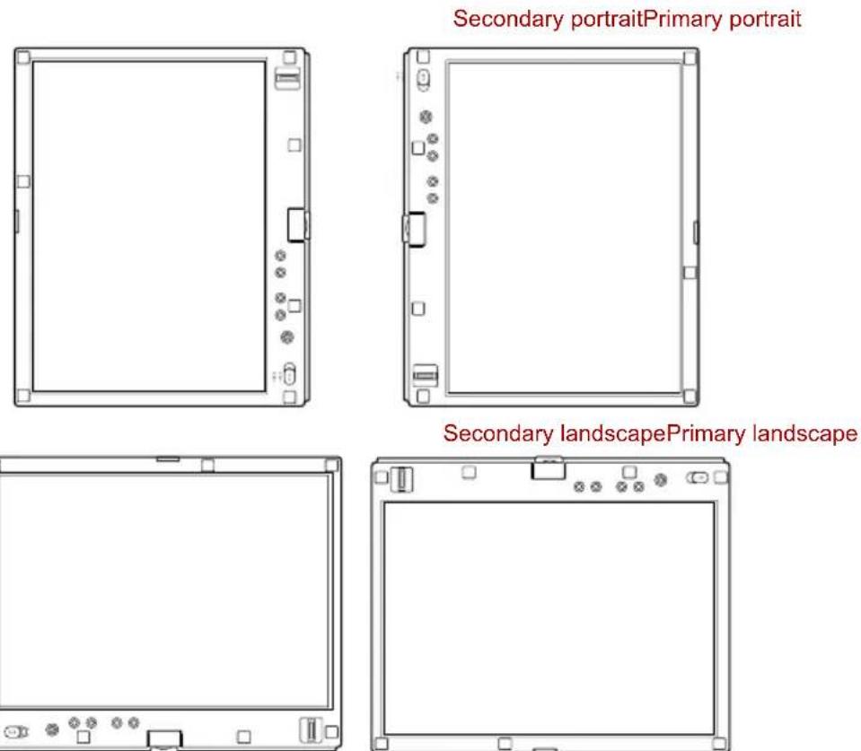
text_image
Secondary portraitPrimary portrait Secondary landscapePrimary landscapeFour display modes

■Execute the following applications on Primary landscape:
■3D game software
■3D screen saver
■Playback of a motion picture as would be the case using DVD-Video playback on the computer connected to an external DVD-ROM Drive.
The screen cannot automatically rotate in the following cases. You should first quit the running application and then rotate the screen:
■Running of an application that changes the screen resolution dynamically, such as a game that is running in full-screen mode.
■DOS prompt in full-screen mode.
■Running of 3D screen saver.

■Do not play 3D game software or replay DVD-Video in a display mode other than Primary landscape. an abnormality will appear on the Windows screen display when you replay a DVD-Video in a mode other than Primary landscape because DVD playback software can boot only in the Primary landscape mode.
An abnormality will appear on the Windows screen display when you change from Tablet Mode to Laptop Mode while a 3D screen saver is running. In this case, press any key while in Laptop Mode to deactivate the 3D screen saver.
Method 1: Changing the screen orientation using TOSHIBA Accelerometer Utilities and TOSHIBA Rotation Utility
When the TOSHIBA Accelerometer Utilities and TOSHIBA Rotation Utility are running, changes in the orientation of the top and bottom of the screen is automatically recognized by pressing ESC/Rotation button for more than a second.
Method 2: Changing the screen orientation using Cross Function Button
- Press the Cross Function Button for more than one second. The TOSHIBA Tablet Menu will appear.
- Select the Internal Monitor icon in Toshiba Shortcut using the Cross Function Button and then press then Cross Function Button.
- Select the rotation angle using Cross Function Button and then press the Cross Function Button.
Method 3: Changing the screen orientation using Task Bar
- Right click "Change tablet and pen settings" icon in the Task Bar. Click "Change screen orientation" from the menu. The screen orientation is set to change in the following order when purchased.
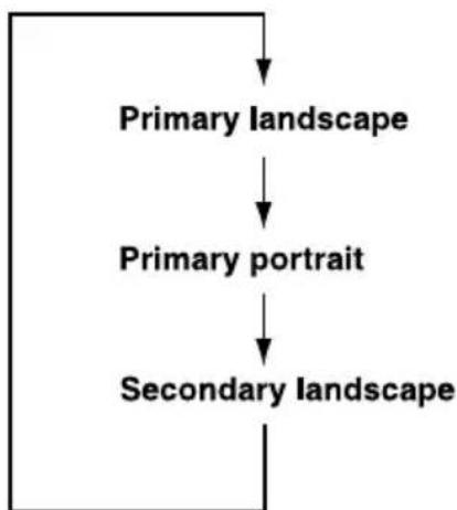
flowchart
graph TD
    A["Primary landscape"] --> B["Primary portrait"]
    B --> C["Secondary landscape"]
You can change the above sequence through the following procedure:
- Double click Change tablet and pen settings icon in the Task Bar.
- Click Change button in Display tab.
- Select "changing the screen" from the Screen Orientation pull down menu and change the screen.

You can set the orientation of the desktop screen just after rotating the display from [Start] - [All Programs] - [TOSHIBA] - [Tablet PC] - [TOSHIBA Rotation Utility].
Using Accelerometer Utilities

When you shake the computer:
Do not shake the computer too strongly as this may cause the computer to be dropped or hit those people or items around you.
■Avoid using the computer in crowded places. (e.g. in commuter trains or in busy streets)
This may cause injury to children or adults, or damage to the computer.

When the HDD protection function is turned on and the Tilt function (function to start applications, etc. by waving the computer vertically or horizontally) is used, the HDD protection message may be displayed on the screen. Turn off the HDD protection function in order to stop such messages from displaying.
It is safer if you hold the computer with both hands horizontally as shown in the below example.
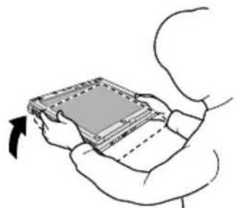
natural_image
Line drawing of a person holding a device with an arrow indicating rotation (no text or symbols)The computer is shaken horizontally.
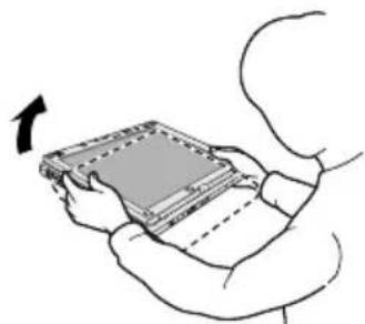
natural_image
Illustration of a person holding a tablet device with an arrow indicating rotation (no text or symbols)The computer is shaken perpendicularly.
Shake the computer
Changing to the laptop mode
To change the operating mode to the Laptop Mode, follow the instructions below.
- Press the Display latch and raise the display to the upright position carefully.
- Rotate the display counter-clockwise slowly.
- Turn the display latch toward you ready for the next closing of the display.
Using the Fingerprint Sensor
This product has a fingerprint utility installed for the purpose of enrolling and recognizing fingerprints. By enrolling the ID and password to the fingerprint authentication device, it is no longer necessary to input the password from the keyboard. Just by swiping the finger against the fingerprint sensor, the following functions will be enabled:
■Logon to Windows and access a security-enabled homepage through IE (Internet Explorer).
■Files and folders can be encrypted/decrypted and third party access to them prevented.
■Disable the password-protected screen-saver when returning from power-saving (standby) mode.
■Power-on Security and Single Sign-on feature.
■Authentication of the User Password and Hard Disk Drive Password when booting up the computer.

To "swipe" refers to the action of reading a fingerprint using the fingerprint sensor.
Points to note about the Fingerprint Sensor
Failure to follow these guidelines might result in (1) damage to the sensor or cause sensor failure, (2) finger recognition problems, or lower finger recognition success rate.
- Do not scratch or poke the sensor with your nails or any hard or sharp objects.
■Do not press the sensor strongly. - Do not touch the sensor with a wet finger or any wet objects. Keep sensor surface dry and free of water vapor.
■Do not touch the sensor with a soiled finger. Minute foreign particles on a soiled or dirty finger may scratch the sensor.
■Do not paste stickers or write on the sensor. - Do not touch the sensor with a finger or any object that has a build-up of static electricity on it.
Observe the following before you place your finger on the sensor whether for fingerprint enrollment/registration or recognition.
■Wash and dry your hands thoroughly.
■ Remove static electricity from your fingers by touching any metal surface. Static electricity is a common cause of sensor failures, especially when the weather is dry.
- Clean the sensor with a lint-free cloth. Do not use detergent to clean the sensor.
■Avoid the following finger conditions for enrollment or recognition as they may result in fingerprint enrollment errors or a drop in the fingerprint recognition success rate
■Soaked or swollen finger (e.g. after taking bath)
Injured finger
Wet finger
■Soiled or oily finger
■Extremely dry skin condition on finger
Observe the following to improve the fingerprint recognition success rate.
■Enroll two or more fingers.
■Enroll additional fingers if recognition failure occurs often using enrolled fingers.
- Check your finger condition. Changed conditions, such as injured, rough, extremely dry, wet, soiled, dirty, oily, soaked, swollen fingers, may lower the recognition success rate. Also if the fingerprint is worn down or the finger becomes thinner or fatter, the recognition success rate may be lowered.
The fingerprint for each finger is different and unique. Please ensure that only the registered or enrolled fingerprint or fingerprints are used for identification.
■Check sliding position and speed (see the drawing and information on the following pages).
How to Delete the Fingerprint Data
Saved fingerprint data is stored in non-volatile memory inside the fingerprint sensor. If you hand over the computer to others, or dispose of it, it is recommended that you perform the following operations.
- Click start, point to All Programs, point to Protector Suite QL and click Control Center.
- The Protector Suite Software screen is displayed.
- Click Fingerprints and click Delete.
- Click Settings and click Fingerprint Storage Inspector.
- The Fingerprint Storage Inspector screen is displayed. If other fingerprint data is still displayed on the list. Select all fingerprint data and click remove.
- Check whether all fingerprint data was deleted on the fingerprint Storage inspector screen.
Fingerprint Sensor Limitations.
■The fingerprint sensor compares and analyzes the unique characteristics in a fingerprint.
A warning message will be displayed when recognition is abnormal or recognition is not successful within a fixed duration.
The recognition success rate may differ from user to user.
■Toshiba does not guarantee that this fingerprint recognition technology will be error-free.
■Toshiba does not guarantee that the fingerprint sensor will recognize the enrolled user or accurately screen out unauthorized users at all times. Toshiba is not liable for any failure or damage that might arise out of the use of this fingerprint recognition software or utility.
The following illustrations show the correct way to slide your finger over the recognition sensor.
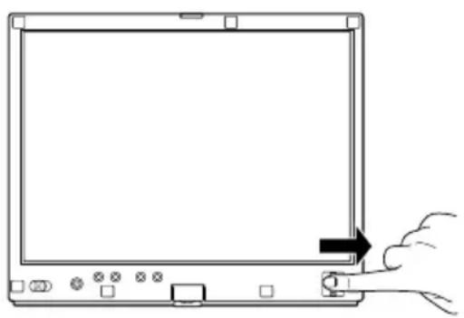
natural_image
Line drawing of a hand pressing a button on a computer monitor (no text or symbols)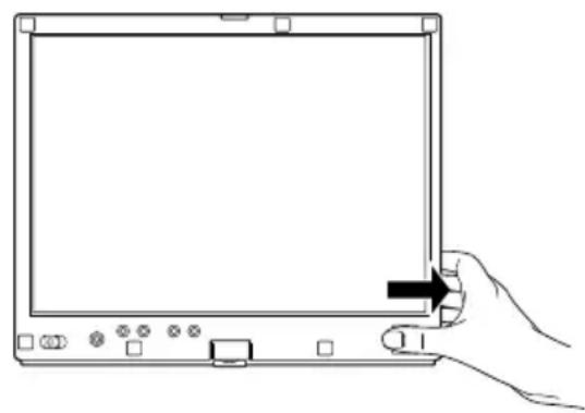
natural_image
Line drawing of a hand holding a tablet device with control buttons and an arrow pointing to the screen (no text or symbols present)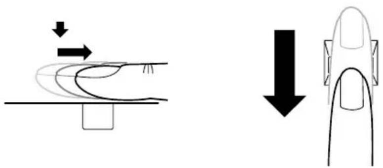
natural_image
Diagram showing two mechanical or fluid dynamics states: a curved pipe with downward arrows and a flat surface with a downward arrow, both without any text or symbols.Align your fingertip with the sensor as shown in the drawing and Swipe
Points to note about the Fingerprint Utility

Backups for saved fingerprint data and saved information in the PasswordBank can be performed in Import or Export User Data under Fingerprint Software Management. However, encrypted files cannot be backed within Mysafe using this function. Instead it is recommended that you backup encrypted files to external media using standard methods such as the file copy process within Windows XP.
If Windows XP's file encryption function EFS (Encryption File System) is used to encrypt a file, the file cannot be further encrypted using the encryption function of this software.
If the fingerprint sensor and Trusted Platform Module (TPM) security are used as identification devices, install and configure the Infineon TPM Professional package first before configuring the fingerprint utility. Please refer to the TPM (Trusted Platform Module) Installation Guide for the installation and configuration methods for TPM.
In the help file, it is stated that this software's PasswordBank function can be used for the Internet and general applications. However, the Internet PasswordBank function in the fingerprint utility provided in this computer can only be used with IE (Internet Explorer).
Set Up Procedure
Please use the following procedure when first using fingerprint authentication.
Fingerprint Registration
Enroll the required authentication data using the "User Enrollment" Wizard.

The fingerprint authentication uses the same Windows logon ID and password. If the Windows logon password has not been setup, please do so before registration.
■ Up to 21 fingerprint patterns can be registered on this sensor.
- Click start, point to All Programs, point to Protector Suite QL and click User Enrollment Wizard.

You can also start User Enrollment Wizard using the following method.
■Click the Protector Suite QL icon in the Task Bar.
■ Swipe your finger across the Fingerprint Sensor.
-
Click Next.
-
The User's Password screen is displayed. Ensure the same Windows logon username is displayed before entering a password into the Enter your password field. Click Next.
- The Hints for Fingerprint Enrollment screen is displayed. Confirm the message and that there is a checkmark in Run Interactive Tutorial, and click Next.
- The Correct Swipe Procedure screen is displayed. Confirm the message and click Next.
- The Scanning Practice screen is displayed. You can practice swiping your finger and when you have finished practicing swiping your finger, click Next.
- The User's Fingers screen is displayed. Based on the illustration, select the finger to be recognized, and then click Next. Previously enrolled fingerprints would have green check marks. The fingerprint being enrolled now would have a red check mark. If any of the previously enrolled fingerprints is selected again, the latest information will be enrolled and previous information over-written.
- The Advanced Security screen is displayed. Select whether to enable the security function, and click Next.
- The Finalization screen is displayed. Click Finish. This completes the fingerprint registration process.
Window Logon via Fingerprint Authentication
In place of the usual Windows logon by ID and password, fingerprint authentication also allows logon to Windows.
This is useful especially when many users are using the same computer as it allows the user selection screen to be skipped.
Fingerprint Authentication Procedure
- Start up the computer.
- The Logon Authorization screen is displayed. Choose any of the enrolled fingers and swipe the fingerprint on the sensor. If authentication is successful, the user will be logged on to Windows.

If the fingerprint authentication fails, please logon using the Windows logon password.
Please logon using the Windows logon password if the fingerprint authentication failed for three consecutive tries. To logon using the Windows logon password, enter the Windows logon password at the "Welcome" screen as normal.
A warning message will be displayed when authentication is abnormal or authentication is not successful within a fixed duration.
Fingerprint Power-on Security
General
The fingerprint authentication system can be used to replace the keyboard-based User/BIOS Password authentication system when booting up.
If you do not want to use the fingerprint authentication system for password authentication when booting up, but prefer to use the keyboard-based system instead, press the BkSP (backspace) key or the ESC/Rotation button when the Fingerprint Power-on Security screen is displayed. This will switch the password input screen to the keyboard-based one.

It is necessary to register the User Password before using the Fingerprint Power-on Security and its extended function, the Fingerprint Single Sign-on Feature. Please use TOSHIBA Password Utility to register the User Password.
If you fail fingerprint authentication more than five times, you must enter the User Password or Supervisor Password manually to start the computer.
When swiping, please do it slowly and at a constant speed. If this does not improve the authentication rate, please adjust the speed.
If there are any changes in the environment or settings related to authorization, you will be required to provide authorization information such as a User Password or Hard Disk Drive password.
How to Enable Fingerprint Power-on Security Settings
It is necessary to first enroll your fingerprint with the Protector Suite QL application prior to enabling and configuring the Fingerprint Power-on Security System. Check that your fingerprint is enrolled before configuring the settings. See Manual for Fingerprint Registration/Enrollment instructions.
- Swipe your finger across the Fingerprint Sensor.
- MENU appears in the lower right corner of the screen. Swipe (*) your finger on the Fingerprint Sensor, and select Control Center from the MENU items.
(*). It is recommended that the keyboard cursor keys (movement) and enter key (selection) or the directional pad be used when selecting an Item from the Menu in laptop or landscape modes.
-
The Fingerprint Software Management screen is displayed. Click Settings and click Power-on Security.
-
The Protector Suite Settings screen is displayed. Place a checkmark in Allow power-on security single sign-on within Enable logon support and click OK.
Fingerprint Single Sign-on Feature
General
This is a feature that allows the user to complete the authentication for both the User/BIOS Password (and optionally the hard disk drive Password) and logging onto Windows using only one fingerprint authentication when booting up. It is necessary to register the User/BIOS Password and Windows Logon Password before using the Fingerprint Power-on Security and this Fingerprint Single Sign-on Feature. Please use the TOSHIBA Password Utility to register your User/BIOS Password. If Windows Logon is not the default for your system, see Manual to register your Windows Logon Password.
Only one fingerprint authentication is required to replace the User/BIOS Password (and, if selected, the hard disk drive Password) and the Windows Logon Password.
How to Enable Fingerprint Single Sign-on Feature
It is necessary to first enroll your fingerprint with the Protector Suite QL application prior to enabling and configuring the How to Enable Fingerprint Single Sign-on Feature. Check that the fingerprint is enrolled before configuring the settings. See Manual for Fingerprint Registration/Enrollment instructions.
- Swipe your finger across the Fingerprint Sensor.
- MENU appears in the lower right corner of the screen. Swipe (*) your finger on the Fingerprint Sensor, and select Control Center from the MENU items.
(*). It is recommended that the keyboard cursor keys (movement) and enter key (selection) or the directional pad be used when selecting an Item from the Menu in laptop or landscape modes. - The Fingerprint Software Management screen is displayed. Click Settings and click System Settings.
- The Power-on Security screen is displayed. Place a checkmark in Allow power-on security single sign-on within Enable logon support and click OK.
Fingerprint utility limitations
TOSHIBA does not guarantee that the Fingerprint utility technology will be completely secure or error-free. TOSHIBA does not guarantee that the Fingerprint utility will accurately screen out unauthorized users at all times. TOSHIBA is not liable for any failure or damage that might arise out of the use of the fingerprint software or utility.
How to Swipe the Finger
Using the following steps when swiping fingers for fingerprint registration or authentication will help to minimize authentication failures:
- Align the first joint of the finger to the center of the sensor. Lightly touch the sensor and swipe finger levelly towards you when in portrait mode, and sideways when in either landscape mode or Laptop mode. While lightly touching the sensor, swipe the finger towards you when in portrait mode, and sideways when in either landscape mode or Laptop mode until the sensor surface becomes visible.

■Avoid swiping with the finger stiff or pressed-on too hard
Fingerprint reading may fail if the center of the fingerprint is not touching on the sensor, or when finger is swiped while pressing hard. Make sure that the center of the fingerprint is touching the sensor before swiping.
■Always confirm the center of the fingerprint whirl so that it is swiped along the centerline of the sensor.
When fingerprint reading is not successful
There is a possibility of authentication failures if the finger is swiped too quickly or too slowly. Follow the onscreen instructions to adjust the speed of the swipe.
Using the USB floppy disk drive (optional)
The USB floppy disk drive accommodates 1.44-megabyte or 720-kilobyte floppy disks and connects to the USB port. Refer to Chapter 2, The Grand Tour, for more information. It is supplied as standard with some models and as an option with others.
Connecting the USB floppy disk drive
To connect the drive, plug the floppy disk drive's USB connector into a computer's USB port.

Make sure the connector is back side up and properly aligned with the socket. Do not try to force the connection, doing so can damage the connecting pins.
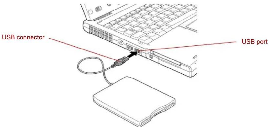
text_image
USB connector USB portConnecting the USB floppy disk drive

If you connect the USB floppy disk drive after turning on the computer, it will take about 10 seconds for the computer to recognize the drive. Do not disconnect and reconnect before 10 seconds has elapsed.
Disconnecting USB floppy disk drive
When you have finished using the USB floppy disk drive, follow the procedures below to disconnect it:
- Wait for the indicator light to go out to make sure all floppy disk activity has stopped.

If you disconnect the USB floppy disk drive or turn off the power while the computer is accessing the drive you may lose data or damage the floppy disk or the drive.
-
Click the Safely Remove Hardware icon on the Task Bar.
-
Click USB floppy disk drive device that you want remove.
-
Pull the floppy disk drive's USB connector out of the computer's USB port.
Changing Ultra Slim Bay modules
This section explains how to change modules in the Ultra Slim Bay. The illustrations show replacement of the optical media drive with the Ultra Slim Bay Hard Disk Drive adaptor. Therefore, the text refers to those modules. However, the procedures are the same for any of the modules: DVD-ROM / CD-R/RW drive, DVD Super Multi drive and Hard Disk Drive adaptor.
To avoid injury, do not put your hand into the Ultra Slim Bay slot.

The TOSHIBA Mobile Extension is preinstalled to support hot swapping under Windows. Refer to Chapter 1, Introduction for information on using this utility to change modules while the computer's power is on.
Removing a module
Remove the Ultra Slim Bay module as described below.
- Wait for the indicator light to go out to make sure all disk activity has stopped.
- Turn the computer upside down.

Wait for all disk indicators to go out before you turn over the computer. Lay the computer down gently as shock can damage the hard disk drive or other components.
- Remove the screw near the icon that holds the Ultra Slim Bay in place.
- Make sure the screw in the Ultra Slim Bay lock screw is set in the hole to the unlock position.
- Slide the Ultra Slim Bay latch to the unlock position.
- Grasp the optical media drive and slide it out.

The optical media drive and other Ultra Slim Bay modules can become hot with use. Be careful when removing the module.
Store the DVD Super Multi drive unit in the Ultra Slim Bay Case when removing it from the computer or transporting it.
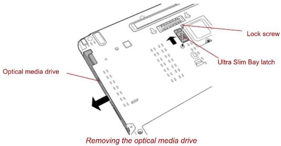
text_image
Optical media drive Removing the optical media drive Lock screw Ultra Slim Bay latchInserting a module
Insert the Ultra Slim Bay Hard Disk Drive adaptor as described below.
- Insert the Ultra Slim Bay Hard Disk Drive adaptor in the computer as shown below and press until the ejector mechanism clicks.
- If you want to lock the Ultra Slim Bay Hard Disk Drive adaptor, place the Ultra Slim Bay lock screw in the hole for its lock position.
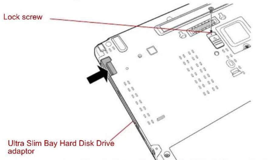
text_image
Lock screw Ultra Slim Bay Hard Disk Drive adaptorInserting the Ultra Slim Bay Hard Disk Drive adaptor
Using optical media drives
The text and illustrations in this section refer primarily to the optical media drive. However, operations are the same for other optical drives in the Ultra Slim Bay. The full-size drive provides high-performance execution of CD/DVD-ROM-based programs. You can run either 12 cm (4.72") or 8 cm (3.15") CD/DVDs without an adaptor. An ATAPI interface controller is used for CD/DVD-ROM operation. When the computer is accessing a CD/DVD-ROM, an indicator on the drive glows and the Ultra Slim Bay indicator glows.

Use the WinDVD application to view DVD-Video discs.
If you have a DVD-ROM / CD-R/RW drive, refer also to the Writing CDs on DVD-ROM / CD-R/RW drive section for precautions on writing to CDs.
If you have a DVD Super Multi drive, refer also to the Writing CD/DVDs on DVD Super Multi drive section for precautions on writing to CDs/DVDs.

When the power of the optical media drive is off, pressing the Fn + Tab keys will turn the power of the optical media drive on. Furthermore, it is possible to set it to turn the power of the optical media drive on and eject the tray at the same time.
Loading discs
To load CD/DVDs, follow the steps below.
- When the computer's power is on, press the eject button to open the disc tray slightly.
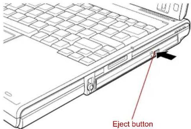
text_image
Eject buttonPressing the eject button
- Grasp the disc tray gently and pull until it is fully opened.
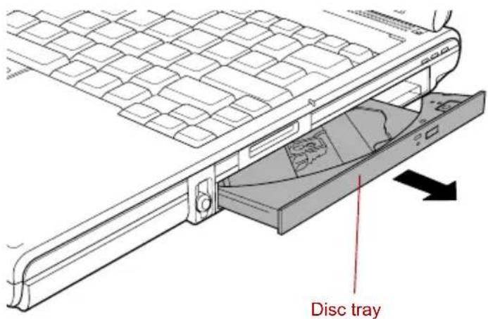
text_image
Disc trayPulling the disc tray open
- Lay the CD/DVD, label side up, in the disc tray.
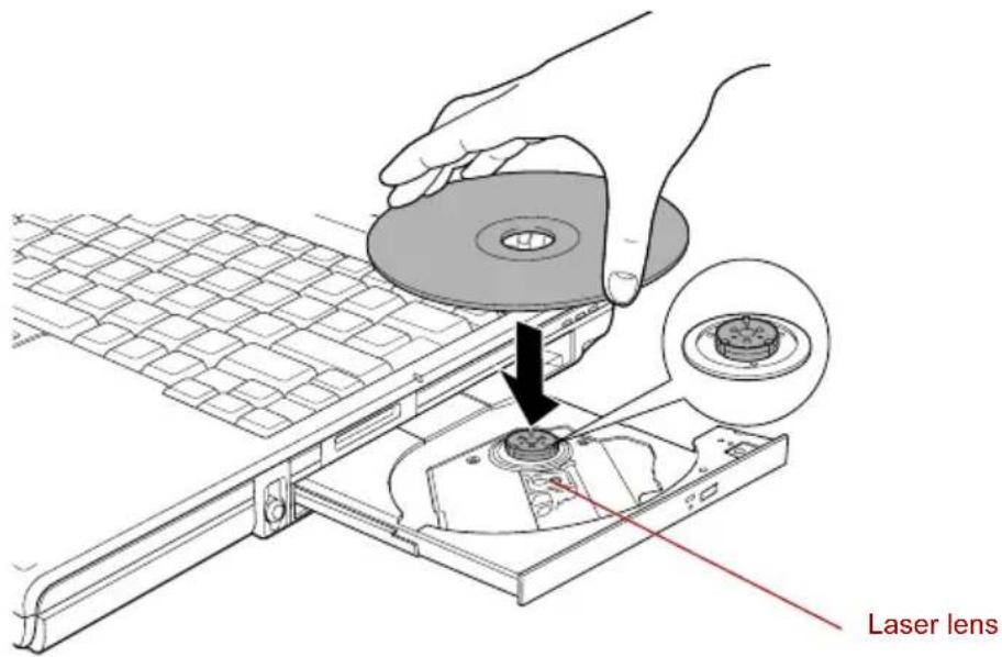
text_image
Laser lensInserting a CD/DVD

When the disc tray is fully opened, the edge of the computer will extend slightly over the CD/DVD tray. Therefore, you will need to turn the CD/DVD at an angle when you place it in the disc tray. After seating the CD/DVD, however, make sure it lies flat.

■Do not touch the laser lens or any portion of its surrounding casing as this could cause misalignment.
■ Prevent foreign objects from entering the drive. Check the surface of the disc tray, especially the area behind the front edge of the disc tray, to make sure there are no such objects before closing the drive.
-
Press gently at the center of the CD/DVD until you feel it click into place. The CD/DVD should lie below the top of the spindle, flush with the spindle base.
-
Push the center of the disc tray to close it. Press gently until it locks into place.

If the CD/DVD is not seated properly when the disc tray is closed, the CD/DVD might be damaged. Also, the disc tray might not open fully when you press the eject button.
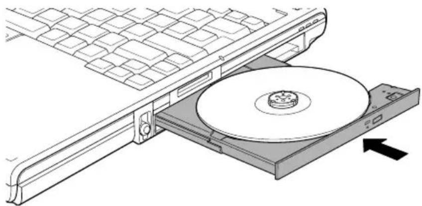
natural_image
Diagram of a CD/DVD drive assembly with an arrow indicating direction (no text or symbols present)Closing the CD/DVD disc tray
Removing discs
To remove the CD/DVD, follow the steps below.

Do not press the eject button while the computer is accessing the media drive. Wait for the Ultra Slim Bay indicator to go out before you open the disc tray. Also, if the CD/DVD is spinning when you open the disc tray, wait for it to stop before you remove it.
- To pop the disc tray partially open, press the eject button. Gently pull the disc tray out until it is fully opened.

When the disc tray pops open slightly, wait a moment to make sure the CD/DVD has stopped spinning before pulling the disc tray fully open.
- The CD/DVD extends slightly over the sides of the disc tray so you can grasp it. Gently lift out the CD/DVD.
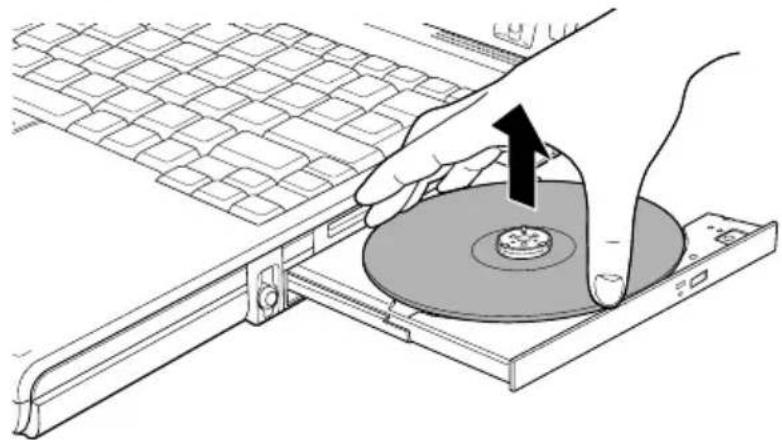
natural_image
Illustration of a hand inserting a CD into a rack, showing the disc being inserted (no text or symbols present)Removing a CD/DVD
- Push the center of the disc tray to close it. Press gently until it locks into place.
How to remove CD/DVD when the disc tray will not open
Pressing the eject button will not open the disc tray when the computer power is off. If the power is off, you can open the disc tray by inserting a slender object (about 15 mm) such as a straightened paper clip into the eject hole just to the right of the eject button.
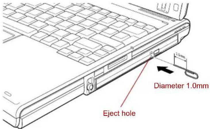
text_image
Diameter 1.0mm Eject holeManual release with the eject hole

Turn off the power before you use the eject hole. If the CD/DVD is spinning when you open the disc tray, the CD/DVD could fly off the spindle and cause injury.
Writing CDs on DVD-ROM / CD-R/RW drive
Depending on the type of drive installed, you may be able to write CDs. The DVD-ROM / CD-R/RW drive lets you write as well as read CD-ROMs. Observe the precautions in this section to ensure the best performance for writing CDs. For information on loading and unloading CDs refer to the Using optical media drives section.

Refer to the Writable discs, Chapter 2 for the details about the types of writable CD/DVD discs.
Do not turn off the power of the optical media drive while the computer is accessing the drive. If you turn off the power, you may lose data.
When the power of the optical media drive is off, the disc tray will not open even if the eject button is pushed. Use the optical drive power to turn the power of the optical media drive on. Refer to Chapter 1, Special features.

When writing to media using an optical drive, always connect the AC adaptor to a power plug socket. If data is written while powered by the batteries, writing may sometimes fail due to low battery power and data loss may occur.
Before writing or rewriting
Please observe the following points when you write or rewrite the data.
We recommend the following manufacturers of CD-R and CD-RW media. Media quality can affect write or rewrite success rates.
CD-R:
TAIYO YUDEN CO., LTD.
Multi-Speed and High-Speed CD-RW:
TOSHIBA has confirmed the operation of CD-R and CD-RW media of the manufacturers above. Operation of other media cannot be guaranteed.
■The actual number of rewrites to CD-RW mdeia is affected by the quality of the disc and the way it is used.
■Be sure to connect the AC adaptor when you write or rewrite.
■Be sure to close all other software programs except the writing software.
■Do not run software such as a screen saver which can put a heavy load on the CPU.
- Operate the computer at full power. Do not use power-saving features.
■Do not write while virus check software is running. Wait for it to finish, then disable virus detection programs including any software that checks files automatically in the background.
Do not use hard disk utilities, including those intended to enhance hard disk drive access speeds. They may cause unstable operation and damage data.
Write from the computer's hard disk drive to the CD. Do not try to write from shared devices such as a LAN server or any other network device.
■Writing with software other than Sonic RecordNow! has not been confirmed. Therefore, operation with other software cannot be guaranteed.
When writing or rewriting
Note the following when you write or rewrite a CD-R or CD-RW.
■Always copy data from the hard disk drive to the optical media. Do not use cut-and-paste as the original data will be lost if there is a write error.
■Do not perform any of the following actions:
■Change users in the Windows XP operating system.
■Operate the computer for any other function, including use of a mouse or Touch Pad, closing/opening the LCD panel.
■Start a communication application such as a modem.
■Apply impact or vibration to the computer.
- Install, remove or connect external devices, including the following: PC card, SD card, Memory Stick/Memory Stick Pro, xD picture card, USB devices, external monitor, i.LINK devices, optical digital devices.
■Open the optical media drive.
■ Remove the optical media drive from the Ultra Slim Bay.
If the media is poor in quality, dirty or damaged, writing or rewriting errors may occur.
- Set the computer on a level surface and avoid places subject to vibration such as airplanes, trains or cars. Do not use an unstable surface such as a stand.
- Keep mobile phones and other wireless communication devices away from the computer.
Writing CD/DVDs on DVD Super Multi drive
You can use the DVD Super Multi drive to write data to either CD-R/RW or DVD-R/-RW/+R/+RW/-RAM discs. The following applications for writing are provided: RecordNow!, and DLA licensed by Sonic Solutions, and InterVideo's WinDVD Creator Platinum.

Refer to the Writable discs, Chapter 2 for the details about the types of writable CD/DVD discs.
■Do not turn off the power of the while the computer is accessing the drive. If you turn off the power, you may lose data.
When the power of the optical media drive is off, the disc tray will not open even if the eject button is pushed. Use the Optical Drive Power icon to turn the power to the drive on. Refer to Chapter 1, Special features.

When writing to media using an optical drive, always connect the AC adaptor to a power plug socket. If data is written while powered by the batteries, writing may sometimes fail due to low battery power and data loss may occur.
Important message
Before you write or rewrite to CD-R/RW or DVD-R/-RW/+R/+RW/-RAM discs, read and follow all setup and operating instructions in this section. If you fail to do so, the DVD Super Multi drive may not function properly, and you may fail to write or rewrite, lose data or incur other damage.
Disclaimer
TOSHIBA does not bear responsibility for the following:
■ Damage to any CD-R/RW or DVD-R/-RW/+R/+RW/-RAM disc that may be caused by writing or rewriting with this product.
■ Any change or loss of the recorded contents of CD-R/RW or DVD-R/-RW/+R/+RW/-RAM disc that may be caused by writing or rewriting with this product, or for any business profit loss or business interruption that may be caused by the change or loss of the recorded contents.
■Damage that may be caused by using third party equipment or software.
Given the technological limitations of current optical disc writing drives, you may experience unexpected writing or rewriting errors due to disc quality or problems with hardware devices. Also, it is a good idea to make two or more copies of important data, in case of undesired change or loss of the recorded contents.
Before writing or rewriting
■Based on TOSHIBA's limited compatibility testing, we suggest the following manufacturers of CD-R/RW and DVD-R/+R/-RW/+RW/-RAM disc. However, in no event does TOSHIBA guarantee the operation, quality or performance of any disc. Disc quality can affect write or rewrite success rates.
CD-R:
TAIYO YUDEN CO., LTD.
CD-RW: (Multi-Speed and High-Speed)
CD-RW: (Ultra-Speed)
DVD Specifications for Recordable Disc for General Version 2.0
TAIYO YUDEN CO., LTD.
Matsushita Electric Industrial Co., Ltd.
DVD-R DL: (Double Layer supported model only)
DVD+R DL: (Double Layer supported model only)
DVD Specifications for Recordable Disc for Version 1.1 or version 1.2
VICTOR COMPANY OF JAPAN.LIMITED
This drive cannot use discs that allow writing faster than 8 speed (DVD-R, DVD+R), 4 speed (DVD-RW, DVD+RW), 5 speed (DVD-RAM), 2.4 speed (DVD-R DL), 2 speed (DVD-R DL).
2.6GB and 5.2GB DVD-RAM media cannot be read from or written to.
Some types and formats of DVD-R DL and DVD+R DL discs may be unreadable.
If the disc is poor in quality, dirty or damaged, writing or rewriting errors may occur. Be careful to check the disc for dirt or damage before you use it.
The actual number of rewrites to CD-RW, DVD-RW, DVD+RW or DVD-RAM is affected by the quality of the disc and the way it is used.
There are two types of DVD-R discs: authoring and general use discs. Do not use authoring discs. Only general use discs can be written to by a computer drive.
- You can use DVD-RAM discs that can be removed from a cartridge and DVD-RAM discs designed without a cartridge.
- Other DVD-ROM drives for computers or other DVD players may not be able to read DVD-R/-RW or DVD+R/+RW discs.
■Data written to a CD-R/DVD-R/DVD+R disc cannot be deleted either in whole or in part.
■Data deleted (erased) from a CD-RW, DVD-RW, DVD+RW and DVD-RAM disc cannot be recovered. Check the content of the disc carefully before you delete it. If multiple drives that can write data to discs are connected, be careful not to delete data from the wrong drive.
In writing to a DVD-R/-RW, DVD+R/+RW or DVD-RAM disc, some disc space is required for file management, so you may not be able to write the full capacity of the disc.
■Since the disc is based on the DVD standard, it might be filled with dummy data if the written data is less than about 1 GB. Even if you write only a small amount of data, it might take time to fill in the dummy data.
■DVD-RAM formatted by FAT32 cannot be read in Windows 2000 without DVD-RAM Driver Software.
- When multiple drives that can write data to discs are connected, be careful not to write to the wrong drive.
■Be sure to connect the AC adaptor before you write or rewrite.
■Before you enter standby/Hibernation Mode, be sure to finish DVD-RAM writing. Writing is finished if you can eject DVD-RAM media.
■Be sure to close all other software programs except the writing software.
■Do not run software such as a screen saver, which can put a heavy load on the CPU.
- Operate the computer in full-power mode. Do not use power-saving features.
■Do not write while virus check software is running. Wait for it to finish and then disable virus detection programs including any software that checks files automatically in the background.
- Do not use hard disk utilities, including those intended to enhance hard disk drive access speed. They may cause unstable operation and data damage.
- CD-RW (Ultra Speed +) media is not supported. If used, data may be lost or damaged.
Write from the computer's hard disk drive to the CD/DVD. Do not try to write from shared devices such as a LAN server or any other network device.
■Writing with software other than RecordNow! and InterVideo WinDVD Creator Platinum are not recommended.
When writing or rewriting
Please observe/consider the following when you write or rewrite to a CD-R/RW, DVD-R/-RW/-RAM or DVD+R/+RW disc.
■Do not perform any of the following actions when writing or rewriting:
■Change users in the Windows XP operating system.
■Operate the computer for any other function, including using a mouse or Touch Pad or closing/opening the LCD panel.
■Start a communication application such as a modem.
■Apply impact or vibration to the computer.
- Install, remove or connect external devices, including the following: PC card, SD card, Memory Stick/Memory Stick Pro, xD picture card, USB devices, external monitor, i.LINK devices, optical digital devices.
■Use the Audio/Video control button to reproduce music or voice.
■Open the optical media drive.
■ Remove the optical media drive from the Ultra Slim Bay.
■Do not use shut down/log off and standby/hibernation while writing or rewriting.
■ Make sure writing or rewriting is completed before going into standby/hibernation. Writing is completed if you can open the DVD-ROM / CD-R/RW or DVD Super Multi drive tray.
- Set the computer on a level surface and avoid places subject to vibration such as airplanes, trains, or cars. Do not use an unstable surface such as a stand.
- Keep mobile phones and other wireless communication devices away from the computer.
■Always copy data from the hard disk drive to the optical media. Do not use cut-and-paste. The original data will be lost if there is a write error.
RecordNow! Basic for TOSHIBA
Note the following limitations when you use RecordNow!:
■DVD-Video cannot be created using RecordNow!.
■DVD-Audio cannot be created using RecordNow!.
- You cannot use RecordNow!'s "Audio CD for Car or Home CD Player" function to record music to DVD-R/-RW or DVD+R/+RW discs.
■Do not use the "Exact Copy" function of RecordNow! to copy DVD-Video and DVD-ROM with copyright protection.
DVD-RAM disc cannot be backed up with the "Exact Copy" function of RecordNow!.
■You cannot back up a CD-ROM or CD-R/RW to DVD-R/-RW or DVD+R/+RW using the "Exact Copy" function of RecordNow!.
- You cannot back up DVD-ROM, DVD-Video, DVD-R/-RW or DVD+R/+RW to CD-R/RW using the "Exact Copy" function of RecordNow!.
■RecordNow! cannot record in packet format.
You might not be able to use the "Exact Copy" function of RecordNow! to back up a DVD-R/-RW or DVD+R/+RW disc that was made with other software on a different DVD-R/-RW or DVD+R/+RW recorder.
If you add data to a DVD-R and DVD+R disc that you have already recorded to, you might not be able to read the added data under some circumstances. It cannot be read in 16-bit operating systems, such as Windows 98SE and Windows Me. In Windows NT4, you will need Service Pack 6 or later to read added data while in Windows 2000, you will need Service Pack 2 or later to read it. Some DVD-ROM and DVD-ROM / CD-R/RW drives cannot read added data regardless of the operating system.
RecordNow! does not support recording to DVD-RAM discs. To record to a DVD-RAM disc, use Explorer or a similar utility.
When you back up a DVD disc, be sure the source drive supports recording to DVD-R/-RW or DVD+R/+RW discs. If the source drive does not support recording to DVD-R/-RW or DVD+R/+RW discs, it might not be backed up correctly.
■When you back up a DVD-R, DVD-RW, DVD+R or DVD+RW, be sure to use the same type of disc.
■You cannot partially delete any data written to a CD-RW, DVD-RW or DVD+RW disc.
Data Verification
To verify that data is written or rewritten correctly, follow the steps below before you write or rewrite a Data CD/DVD.
-
Click the Options button ( 📄 ) on the RecordNow! Console to open the Options panels.
-
Select Data from the left-hand menu.
-
Mark the Verify data written to the disc after burning check box in the Data Options.
Click the OK button.
DLA for TOSHIBA
Note the following limitations when you use DLA:
This software supports only rewritable discs (DVD+RW, DVD-RW, and CD-RW). It does not support DVD+R, DVD-R, and CD-R discs that are not rewritable.
■DLA does not support formatting and writing to a DVD-RAM disc - these functions are performed by DVD-RAM Driver Software. Even if the DLA Format menu appears when inserting a DVD-RAM disc and right-clicking the drive icon in Windows Explorer, you should use the 'DVDForm' command to format this disc. You can run 'DVDForm' by clicking the Start button on the taskbar to display the Start menu and then selecting 'All Programs', 'DVD-RAM', 'DVD-RAM Driver' and 'DVDForm' sequentially.
Do not use any discs that have been formatted with packet writing software other than DLA. Similarly, do not use any discs that have been formatted with DLA with any packet writing software other than DLA. When using a disc you are not familiar with, format it by selecting "Full Format" before using it.
Do not use the cut-and-paste function for files and folders. A file or folder that has been cut may be lost if writing fails due to an error on the disc.
When writing any setup files for an application to a disc formatted by DLA, and attempting to start Setup from this disc, an error may occur. In this case, please copy the files to your hard disk and then run Setup from there.
When using WinDVD Creator Platinum
You can record video back to your digital camcorder via i.LINK (IEEE 1394) using WinDVD Creator Platinum. However, there is a case where its playback sound appears choppy - in this instance please follow the instructions below:
- Click start and select the Control Panel.
- Click the Performance and Maintenance icon in the Control Panel.
- Click the System icon in the Performance and Maintenance window.
- Click the Advanced tab in the System Properties window.
- Click the Settings icon in the "Performance" section.
- Click the Advanced tab in the Performance Options window.
- Click the Change icon in the "virtual memory" section.
- Select the Custom size button in the Virtual Memory window.
- Specify much higher values for "Initial size" and "Maximum size."
- Click the Set button in the Virtual Memory window.
- Click the OK button in the Virtual Memory window.
How to make a DVD-Video
Simplified steps for making a DVD-Video from video data captured from a DV-Camcorder:
- Click [Start] - [All Programs] - [InterVideo WinDVD Creator2] - [InterVideo WinDVD Creator] to launch WinDVD Creator.
- Click [Capture] button then capture the video data from the DV-Camcorder via IEEE1394.
- Click [Edit] button then drag the video clips from [Video Library] tab to the edit track.
- Click [Make Movie] button in the top bar.
- Double Click the Right arrow button icon in the center of right side.
- Put a blank DVD-R/+R disc or an erased DVD-RW/+RW disc in the drive.
- Click [Start] to record to the disc.
- When recording is finished, the tray opens.
How to learn more about InterVideo WinDVD Creator
Please refer to the on-line Help for additional InterVideo WinDVD Creator information.
Important information for use
Note the following limitations when you write to a video DVD:
- Editing digital video
■Log in with Administrator rights to use WinDVD Creator.
■ Make sure that your computer is running on AC power when using WinDVD Creator.
■Operate the computer at Full Power. Do not use power-saving features.
■While you are editing a DVD-Video, you can display previews. However, if another application is running, the preview might not display properly.
WinDVD Creator cannot show video on the external monitor when in simultaneous mode.
■ WinDVD Creator cannot edit or play copy protected content.
■Do not change display settings while using WinDVD Creator.
■Do not enter standby/Hibernation Mode while using WinDVD Creator.
■Do not operate WinDVD Creator immediately after turning on the computer. Please wait until all disk/disc drive activity has stopped.
■When recording to a DV-Camcorder, to ensure you capture all of your data, let the camcorder record for a few seconds before you begin recording your actual data.
- CD recorder, JPEG functions, DVD-Audio, mini DVD and Video CD functions are not supported in this version.
■While recording video to DVD or tape, please close all other programs.
■Do not run software like a screen saver because it can put a heavy load on the CPU.
■Do not run communication applications like a modem or a LAN.
2. Before recording the video to DVD
■When you record to DVD discs, please use only media recommended by TOSHIBA.
■Do not set the working drive to a slow device like a USB 1.1 hard disk drive or it will fail to write the DVD.
■Do not perform any of the following actions:
- Operate the computer for any other function, including using a mouse or Touch Pad or closing/opening the LCD panel.
■Bump or cause vibration to the computer.
■Use the Mode control button and Audio/Video control button to reproduce music or voice.
■Open the optical media drive.
■Install, remove or connect external devices, including the following:
PC card, SD card, Memory Stick/Memory Stick Pro, xD picture card, USB devices, external monitor, i.LINK devices, optical digital devices.
■Please verify your disc after recording important data.
DVD-R/+R/-RW discs cannot be written in VR format.
■WinDVD Creator cannot export to DVD-Audio, VideoCD or miniDVD format.
■WinDVD Creator can write DVD-RAM/+RW in VR format, but the disc may only play on your computer.
■When writing to a DVD disc, WinDVD Creator requires 2GB or more of disk space for every one hour of video.
■When you make a fully recorded DVD, the chapter sequence may not play correctly.
3. About Disc Manager
■WinDVD Creator can edit one play list on a disc.
■WinDVD Creator might show a different thumbnail than you previously set in CE (Consumer Electronics) DVD-RAM recorder.
■Using the Disc Manager, you can edit DVD-VR format on DVD-RAM, DVD+VR format on DVD+RW, and DVD-Video format on DVD-RW.
4. About recorded DVDs
■Some DVD-ROM drives for personal computers or other DVD players may not be able to read DVD-R/+R/-RW/+RW/-RAM discs.
■When playing your recorded disc on your computer, please use the WinDVD software application.
If you use an over-used rewritable disc, the full formatting might be locked. Please use a brand new disc.
Media care
This section provides tips on protecting data stored on your CD/DVDs and floppy disks.
Handle your media with care. The following simple precautions will increase the lifetime of your media and protect the data stored on them:
CD/DVDs
- Store your CD/DVDs in the container they came in to protect them and keep them clean.
- Do not bend the CD/DVD.
- Do not write on, apply a sticker to, or otherwise mar the surface of the CD/DVD that contains data.
- Hold the CD/DVD by its outside edge or the edge on the center hole. Fingerprints on the surface can prevent the drive from properly reading data.
- Do not expose to direct sunlight, extreme heat or cold. Do not place heavy objects on your CD/DVDs.
- If your CD/DVDs become dusty or dirty, wipe them with a clean dry cloth. Wipe from the center out, do not wipe in a circular direction around the CD/DVD. If necessary, use a cloth dampened in water or a neutral cleaner. Do not use benzine, thinner or similar cleaner.
Floppy disks
- Store your floppy disks in the container they came in to protect them and keep them clean. If a floppy disk is dirty, do not use cleaning fluid. Clean it with a soft damp cloth.
- Never open the shutter or touch the magnetic surface of your floppy disk. You could permanently damage it and lose data.
- Always handle floppy disks with care, to prevent the loss of stored data. Always apply the floppy disk label in the correct location. Never apply a new label on top of an existing one. The label could come loose and damage the floppy drive.
- Never use a pencil for writing on a floppy disk label. Pencil lead dust could cause a system malfunction. Always use a felt-tipped pen. When writing a title on a label, first write on the label, then apply the label to the floppy disk.
- Never put a floppy disk in a location where water or other liquid may contact it or where it is excessively damp. It could cause data loss. Never use a wet or damp floppy disk. It could damage the floppy disk drive or other devices.
- Data may be lost if the floppy disk is twisted; bent; or exposed to direct sunlight, extreme heat or cold.
-
Do not place heavy objects on your floppy disks.
-
Do not eat, smoke, or use erasers near your floppy disks. Foreign particles inside the floppy disk's jacket can damage the magnetic surface.
- Magnetic energy can destroy the data on your floppy disks. Keep your floppy disks away from speakers, radios, television sets and other sources of magnetic fields.
Sound System
This section describes audio controls including sound levels and power management.
Volume Control
The Volume Control utility lets you control the audio volume in Windows for both playback and recording.
To launch Volume Control for playback, click start, point to All Programs, point to Accessories, point to Entertainment and click Volume Control.
To launch Recording Control, click Options, point to Properties, choose Recording and click OK.
■ To view details of the Volume Control, click Help on the Volume Control.
Microphone level
The change the microphone gain, follow the steps below.
- Click start, point to All Programs, point to Accessories, point to Entertainment and click Volume Control.
- Click Options and point to Properties.
- Select Recording and click OK.
- Click Options and select Advanced Controls.
- Click Advanced.
- Check the Microphone Boost checkbox.
SigmaTel Control Panel
SigmaTel Control Panel lets you control some of the audio settings. Follow the steps below to launch the SigmaTel Control Panel:
- Click start and click Control Panel.
- If you are viewing the Control Panel in Category View, click on Switch to Classic View.
- Double-click the SigmaTel Audio icon.
Volume control
To adjust the audio volume in Windows for both playback and recording, click the Levels tab.
To hear the voice from a microphone or the analog sound from the line input, disable the Mute button in the Input Monitor, and then disable the Audio power management function described below.
Audio power management
The audio controller can be powered down when the audio function is not used. To disable audio power management, follow the steps below.
- Click the Advanced tab.
- Check the Enable Power Management check box.
- Input a time in Time to Power Saving State.
If the Enable Power Management check box is not checked, the audio controller will always be in operation.
Graphic equalizer
Adjust the equalizer settings to enhance sound quality.
TOSHIBA Mic Effect
TOSHIBA Mic Effect provides you with a hands-free environment for holding mutual communication via the Internet Protocol or Local Area Network. If you wish to communicate with someone on your computer, you can use a messenger application. However, with such an application, you would hear your own voice returning to you as echo during the communication if you did not use a headset system or headphone.
TOSHIBA Mic Effect will reduce these echoes generated on your computer. TOSHIBA Mic Effect also provides you the Microphone Array. The Microphone Array function eliminates sounds and noise originating outside the range by specifying the target range and direction of the microphone input.
For more instructions for this software, click start, point to All Programs, point to TOSHIBA, point to Utilities and click TOSHIBA Mic Effect Help.
Modem
Click the icon with the secondary mouse button to display the properties menu on the screen.

■Connection to any communication line other than an analog phone line could cause a PC system failure.
■Connect the built-in modem only to ordinary analog phone lines.
■Never connect the built-in modem to a digital line (ISDN).
■Never connect the built-in modem to the digital connector on a public telephone or to a digital private branch exchange (PBX).
■Never connect the built-in modem to a key telephone system for residences or offices.
■Never operate your PC on AC power during a thunderstorm. If you see lightning or hear thunder, immediately turn off the PC. An electric surge caused by the storm, may result in a system failure, loss of data or hardware damage.
Region selection
Telecommunication regulations vary from one region to another, so you will need to make sure the internal modem's settings are correct for the region in which it will be used.

The built-in modem can be used only in specified countries and regions. Using the modem in an area not specified for use may cause a system failure. Check the specified areas carefully before using it.
To select a region, follow the steps below.
- Click start, point to All Programs, point to TOSHIBA, point to Networking and click Modem Region Select.

Do not use the Country/Region Select function in the Modem setup utility in the Control Panel if the function is available. If you change the Country/Region in the Control Panel, the change may not take effect.
- The Region Selection icon will appear in the Windows Task Bar.
- Click the icon with the primary mouse button to display a list of regions that the modem supports. A sub menu for telephony location information will also be displayed. A check will appear next to the currently selected region and telephony location.
- Select a region from the region menu or a telephony location from the sub-menu.
When you click a region it becomes the modem's region selection, and the New Location for telephony will be set automatically.
When you select a telephony location, the corresponding region is automatically selected and it becomes the modem's current region setting.
Properties menu
Click the icon with the secondary mouse button to display properties menu on the screen.
Setting
You can enable or disable the following settings:
AutoRun Mode
The Region Select utility starts automatically when you start up the operating system.
Open the Dialing Properties dialog box after selecting region.
The dialing properties dialog box will be displayed automatically after you select the region.
Location list for region selection.
A submenu appears displaying location information for telephony.
Open dialog box, if the modem and Telephony Current Location region code do not match.
A warning dialog box is displayed if current settings for region code and telephony location are incorrect.
Modem Selection
If the computer cannot recognize the internal modem, a dialog box is displayed. Select the COM port for your modem to use.
Dialing Properties
Select this item to display the dialing properties.

If you are using the computer in Japan, the Telecommunications Business Law requires that you select Japan region mode. It is illegal to use the modem in Japan with any other selection.
Connecting
To connect the modular cable, follow the steps below.

Use a modular cable (optional) to connect the modem to the telephone system. Connect the end of the modular cable with the core to the computer.

■Connection to any communication line other than an analog phone line could cause a PC system failure.
■Connect the built-in modem only to ordinary analog phone lines.
■Never connect the built-in modem to a digital line (ISDN).
■Never connect the built-in modem to the digital connector on a public telephone or to a digital private branch exchange (PBX).
■Never connect the built-in modem to a key telephone system for residences or offices.
■Never operate your PC on AC power during a thunderstorm. If you see lightning or hear thunder, immediately turn off the PC. An electric surge caused by the storm, may result in a system failure, loss of data or hardware damage.
- Plug one end of the modular cable into the computer's modem jack.
- Plug the other end of the modular cable into a telephone jack.
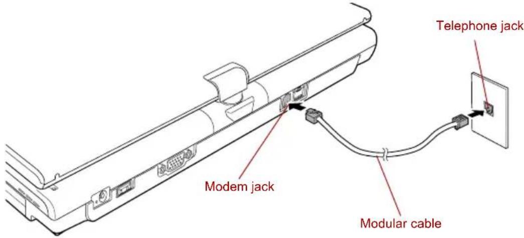
text_image
Telephone jack Modem jack Modular cableConnecting the internal modem

Do not pull on the cable or move the computer while the cable is connected.

If you use a storage device such as an optical drive or hard disk drive connected to a 16-bit PC card, you might experience the following modem problems:
Modem speed is slow or communication is interrupted.
■ Skips may occur in sound.
Disconnecting
To disconnect the internal modular cable, follow the steps below.
- Pinch the lever on the connector in the telephone jack and pull out the connector.
- Disconnect the cable from the computer's modem jack in the same manner.
Wireless communications
The computer's wireless communication function supports both Wireless LAN and Bluetooth devices.
All models are provided with a wireless communication switch. Some models are equipped with both Wireless LAN and Bluetooth functions.
Wireless LAN
The Wireless LAN is compatible with other LAN systems based on Direct Sequence Spread Spectrum / Orthogonal Frequency Division Multiplexing radio technology that complies with the IEEE802.11 Wireless LAN standard (Revision A, B or G).

Do not install or remove an optional memory module while Wake-up on Wireless LAN is enabled.

The Wake-up on Wireless LAN function consumes power even when the system is off. Leave the AC adaptor connected while using this feature.
The Wake-up on Wireless LAN function is effective only when it is connected with an Access Point. This function becomes invalid when the connection is broken.
■Theoretical maximum speed: 54Mbps (IEEE802.11a, 802.11g).
■Theoretical maximum speed: 11Mbps (IEEE802.11b).
■Frequency Channel Selection (Revision A: 5 GHz, Revision B/G: 2.4 GHz).
■Roaming over multiple channels.
Card Power Management.
■Wired Equivalent Privacy (WEP) data encryption, based on the 128 bit encryption algorithm.
■Wi-Fi Protected Access (WPA).
■Advanced Encryption Standard (AES) data encryption.
■Wake-up on Wireless LAN.

The values shown above are the theoretical maximums for Wireless LAN standards. The actual values may differ.
The transmission speed over the wireless LAN, and the distance over which the wireless LAN can reach, may vary depending on surrounding electromagnetic environment, obstacles, access point design and configuration, client design and software/hardware configurations. The transmission rate described is the theoretical maximum speed as specified under the appropriate standard - the actual transmission speed will be lower than the theoretical maximum speed.
Security
■ TOSHIBA strongly recommend that you enable WEP (encryption) functionality, otherwise your computer will be open to illegal access by an outsider using a wireless connection. If this occurs, the outsider may illegally access your system, eavesdrop, or cause the loss or destruction of stored data.
■ TOSHIBA is not liable for the loss of data due to eavesdropping or illegal access through the wireless LAN and the damage thereof.
Bluetooth wireless technology (optional)
Bluetooth ^™ wireless technology eliminates the need for cables between electronic devices such as desktop computers, printers and mobile phones.
You cannot use the built-in Bluetooth functions and an optional Bluetooth SD card simultaneously.
Bluetooth wireless technology has the following features:
Worldwide operation
The Bluetooth radio transmitter and receiver operate in the 2.4 GHz band, which is license-free and compatible with radio systems in most countries in the world.
Radio links
You can easily establish links between two or more devices. The link is maintained even if the devices are not within line of sight.
Security
Two advanced security mechanisms ensure a high level of security:
■Authentication prevents access to critical data and makes it impossible to falsify the origin of a message.
■Encryption prevents eavesdropping and maintains link privacy.
Bluetooth™ Stack for Windows® by TOSHIBA
Please note that this software is specifically designed for the following operating systems:
■Microsoft ^® Windows ^® 2000 Professional
■Microsoft ^® Windows ^® XP
Detailed information regarding the use with these operating systems is listed below. Please refer also to the electronic information which is included with each software.

This Bluetooth™ Stack is based on the Bluetooth™ Version
1.1/1.2/2.0+EDR specification. TOSHIBA cannot confirm compatibility between any PC products and/or other electronic devices that use Bluetooth™ other than TOSHIBA mobile computers.
Release Notes related to the Bluetooth™ Stack for Windows® by TOSHIBA
- Install:
When installing the Bluetooth™ Stack for Windows® by TOSHIBA software under Windows 2000 or Windows XP, please be aware that it is not digitally signed.
- Fax application software:
There is some fax application software that you cannot use on this Bluetooth ^™ Stack.
- Multi User:
On Windows XP, the use of Bluetooth is not supported in a multi-user environment. This means that, when you use Bluetooth, other users logged onto the same computer will not be able to use its Bluetooth functionality.
Product Support:
The latest information regarding Operating System support, Language Support or available upgrades can be found on our web site http://www.toshiba-europe.com/computers/tnt/bluetooth.htm in Europe or www.pcsupport.toshiba.com in the United States.
Wireless communication switch
You can enable or disable Wireless LAN and Bluetooth functions, with the on/off switch. No transmissions are sent or received when the switch is off. Slide the switch to the right to turn it on and to the left to turn it off.

Do not use the Wireless LAN (WiFi) or Bluetooth functionalities near a microwave oven or in areas subject to radio interference or magnetic fields. Interference from a microwave oven or other source can disrupt WiFi or Bluetooth operation.
■Turn WiFi and Bluetooth functionalities off when near a person who may have a cardiac pacemaker implant or other medical electric device. Radio waves may affect pacemaker or medical device operation, possibly resulting in serious injury. Follow the instruction of your medical device when using any WiFi or Bluetooth functionality.
Always turn off WiFi or Bluetooth functionality if the PC is near automatic control equipment or appliances such as automatic doors or fire detectors. Radio waves can cause malfunction of such equipment, possibly resulting in serious injury.
Wireless communication Indicator
The wireless communication indicator indicates the status of the wireless communication functions.
Indicator status Indication
| Indicator off | Wireless communication switch is set to off. Automatic power down because of overheating. Power malfunction. |
| Indicator glows Wireless communication switch is on. Wireless LAN or Bluetooth is turned on by an application. | |
If you used the Task Bar to disable the wireless LAN, restart the computer or perform the following procedure to re-enable it: start, Control Panel, System, Hardware Device Manager, Network adapters, Intel® PRO/Wireless 3945BG/3945ABG Network Connection and enable.
LAN
The computer has built-in support for Ethernet LAN (10 megabits per second, 10BASE-T), Fast Ethernet LAN (100 megabits per second, 100BASE-TX) and Gigabit Ethernet LAN (1000 megabits per second, 1000BASE-T).
This section describes how to connect/disconnect to a LAN.

Do not install or remove an optional memory module while Wake-up on LAN is enabled.

The Wake-up on LAN function consumes power even when the system is off. Leave the AC adaptor connected while using this feature.
LAN cable types

The computer must be configured properly before connecting to a LAN. Logging onto a LAN using the computer's default settings could cause a malfunction in LAN operation. Check with your LAN administrator regarding set-up procedures.
If you are using Gigabit Ethernet LAN (1000 megabits per second, 1000BASE-T), be sure to connect with a CAT5E cable or higher. You cannot use a CAT3 or CAT5 cable.
If you are using Fast Ethernet LAN (100 megabits per second, 100BASE-TX), be sure to connect with a CAT5 cable or higher. You cannot use a CAT3 cable.
If you are using Ethernet LAN (10 megabits per second, 10BASE-T), you can connect with a CAT3 or higher cable.
Connecting LAN cable
To connect the LAN cable, follow the steps below.

■Connect the AC adaptor before connecting the LAN cable. The AC adaptor must remain connected during LAN use. If you disconnect the AC Adaptor while the computer is accessing a LAN, the system may hang up.
Do not connect any other cable to the LAN jack except the LAN cable. Otherwise, malfunctions or damage may occur.
Do not connect any power supplying device to the LAN cable that is connected to the LAN jack. Otherwise, malfunctions or damage may occur.
- Turn off the power to the computer and to all external devices connected to the computer.
- Plug one end of the cable into the LAN jack. Press gently until you hear the latch click into place.
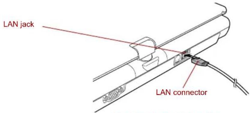
text_image
LAN jack LAN connectorConnecting the LAN cable
- Plug the other end of the cable into a LAN hub connector. Check with your LAN administrator before connecting to a hub.

When the computer is exchanging data with the LAN, the LAN Active indicator glows orange. When the computer is connected to a LAN hub but is not exchanging data, the Link indicator glows green.
Disconnecting LAN cable
To disconnect the LAN cable, follow the steps below.

Make sure the LAN Active indicator (orange LED) is out before you disconnect the computer from the LAN.
- Pinch the lever on the connector in the computer's LAN jack and pull out the connector.
- Disconnect the cable from the LAN hub in the same manner. Check with your LAN administrator before disconnecting from the hub.
Cleaning the computer
To help ensure long, trouble-free operation, keep the computer free of dust and use care with liquids around the computer.
■Be careful not to spill liquids into the computer. If the computer does get wet, turn the power off immediately and let the computer dry completely before you turn it on again.
- Clean the computer using a slightly damp (with water) cloth. You can use glass cleaner on the LCD display screen. Spray a small amount of cleaner on a soft, clean cloth and wipe the screen gently with the cloth.

Never spray cleaner directly onto the computer or let liquid run into any part of it. Never use harsh or caustic chemical products to clean the computer.
Moving the computer
The computer is designed for rugged durability. However, a few simple precautions taken when moving the computer will help ensure trouble-free operation.
■Before moving the computer, it is recommended that you change the function of the HDD Protection. Refer to the section, Using the Hard Disk Drive (HDD) Protection, in this chapter.
■Make sure all disk activity has ended before moving the computer. Check the HDD indicator on the computer.
If a CD/DVD is in the drives, remove it. Also make sure the disc tray is securely closed.
■Turn off the power to the computer.
■ Disconnect the AC adaptor and all peripherals before moving the computer.
■Close the LCD display panel. Do not pick up the computer by its display panel.
■Before carrying your computer, shut down the computer, disconnect the power cable and wait until the PC cools down. Failure to follow this instruction could result in minor injury.
■Always turn off the power when you move the computer. If the power button has a lock, set it to the lock position. Also be careful not to subject the computer to impact. Failure to follow this instruction could result in damage to computer, computer failure or loss of data.
■Never transport your computer with PC cards installed. This could cause damage to your computer and/or PC card, resulting in product failure.
■Use a carrying case when transporting the computer.
■When carrying your computer, be sure to hold it securely so that it does not fall or hit anything.
- Do not carry your computer by holding any protruding areas.
Using the Hard Disk Drive (HDD) Protection
This computer has a function for reducing the risk of damage on the hard disk drive.
Using an acceleration sensor built into the computer, HDD Protection detects vibration, shocks and similar signs of movement of the computer, and automatically moves the hard disk drive head to a safe position to reduce the risk of damage that could be caused by head-to-disk contact.

This function does not guarantee that the hard disk drive will not be damaged.
The secondary hard disk drive is not supported by the HDD protection function.
When vibration is detected, the following message is displayed, and the icon in the notification area of the taskbar is changed to the protection state. This message is displayed until the OK button is pressed or 30 seconds pass. When vibration subsides, the icon returns to the normal state.
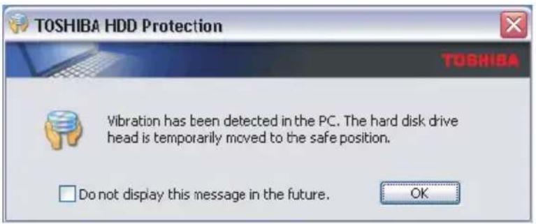
text_image
TOSHIBA HDD Protection TOSHIBA Vibration has been detected in the PC. The hard disk drive head is temporarily moved to the safe position. Do not display this message in the future. OKHDD Protection Message
Taskbar Icon
State Icon Description
Normal HDD Protection is enabled.

Protection HDD Protection is active. The hard disk drive
head is in a safe position.
OFF HDD Protection is disabled.

TOSHIBA HDD Protection Properties
You can change the HDD Protection settings by using the TOSHIBA HDD Protection Properties window. To open the window, click start, point to All Programs, point to TOSHIBA, point to Utilities and click HDD Protection Setting. The window can also be started from the icon on the Taskbar or from the Control Panel.
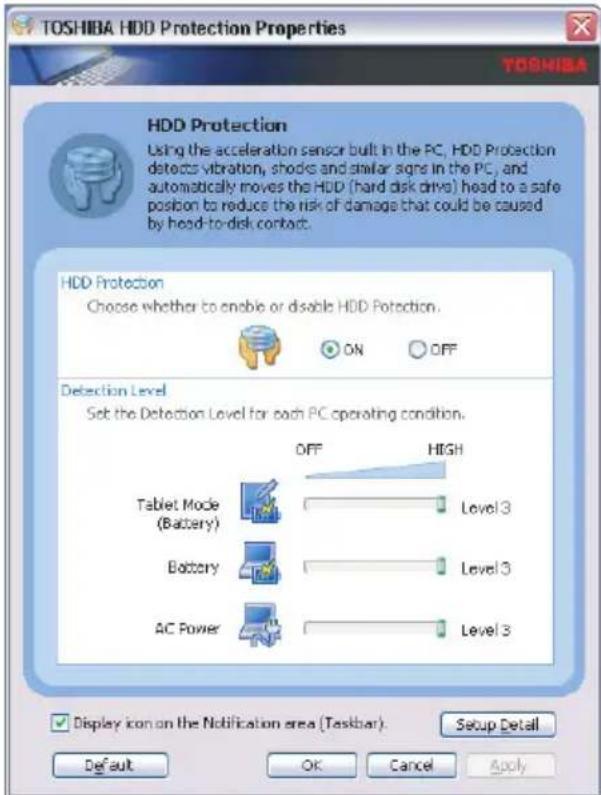
text_image
TOSHIBA HDD Protection Properties TOSHIBA HDD Protection Using the acceleration sensor built in the PC, HDD Protection detects vibration, shocks and similar signs in the PC, and automatically moves the HDD (hard disk drive) head to a safe position to reduce the risk of damage that could be caused by head-to-disk contact. HDD Protection Choose whether to enable or disable HDD Protection. ON OFF Detection Level Set the Detection Level for each PC operating condition. OFF HIGH Tablet Mode (Battery) Level 3 Battery Level 3 AC Power Level 3 Display icon on the Notification area (Taskbar). Setup Detail Default OK Cancel ApplyTOSHIBA HDD Protection Properties
HDD Protection
You can choose whether to enable or disable HDD Protection.
Detection Level
This function can be set to four levels. The sensitivity levels in which vibrations, impacts and their similar signs are detected can be set to OFF, 1, 2 and 3 in ascending order. Level 3 is recommended for better protection of the computer. However, when the computer is used in a mobile environment or in other unstable conditions, setting the detection level to 3 could result in frequent execution of HDD Protection, which will slow hard drive reading and writing. Set a lower detection level when the speed of hard drive reading and writing is a priority.
Different detection levels can be set depending on whether the computer is used as handheld or mobile usages, or whether it is used in a stable environment such as on a table in the workplace or at home. By setting different detection levels for the computer depending on whether it runs with the AC power (desktop) or with batteries (handheld or mobile usage), the detection level automatically switches according to the power connection mode.
Details
To open the Details window, click the Setup Detail button in the TOSHIBA HDD Protection Properties window.
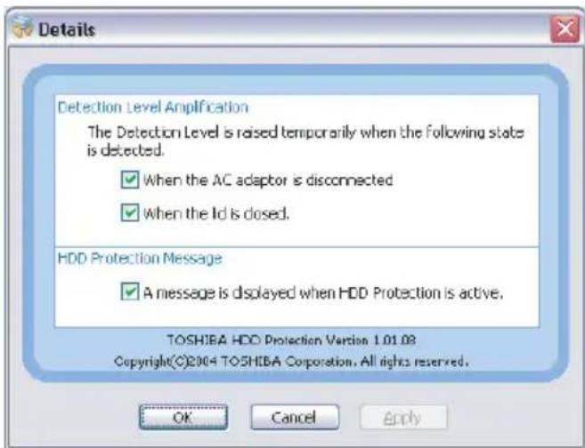
text_image
Details Detection Level Amplification The Detection Level is raised temporarily when the following state is detected. ✓ When the AC adaptor is disconnected ✓ When the Id is dosed. HDD Protection Message ✓ A message is displayed when HDD Protection is active. TOSHIBA HDD Protection Version 1.01.03 Copyright(©)2004 TOSHIBA Corporation. All rights reserved. OK Cancel ApplyDetails
Detection Level Amplification
When the AC adaptor is disconnected or the lid is closed, HDD Detection assumes that the computer will be carried and sets the detection level to the maximum for 10 seconds.
HDD Protection Message
Specify whether to display a message when HDD Protection is active.

This function does not work when the computer is starting, in standby, in hibernation, in transition to hibernation, recovering from hibernation, or powered off. Be sure to not subject the computer to vibration or impact while the function is disabled.
This function only operates with Windows ^ XP.
Heat dispersal
To protect from overheating, the CPU has an internal temperature sensor. If the computer's internal temperature rises to a certain level, the cooling fan is turned on or the processing speed is lowered. You can select whether to control the CPU temperature by turning on the fan first, then if necessary, lowering the CPU speed. Or, by lowering the CPU speed first, then if necessary, turning on the fan. Use the Cooling Method item of the Basic Setup tab in TOSHIBA Power Saver.
When the CPU temperature falls to a normal range, the fan is turned off and the CPU operation returns to standard speed.

If the CPU temperature reaches an unacceptably high level with either setting, the system automatically shuts down to prevent damage. Data in memory will be lost.
Chapter 5
The Keyboard
The computer's keyboard layouts are compatible with a 101/102-key enhanced keyboard. By pressing some keys in combination, all the 101/102-key keyboard functions can be executed on the computer.
The number of keys on your keyboard depends on which country/region's keyboard layout your computer is configured with. Keyboards for numerous languages are available.
There are six types of keys: typewriter keys, function keys, soft keys, Hot keys, Windows special keys and keypad overlay.
Typewriter keys
The typewriter keys produce the upper- and lower-case letters, numbers, punctuation marks, and special symbols that appear on the screen.
There are some differences, however, between using a typewriter and using a computer keyboard:
■Letters and numbers produced in computer text vary in width. Spaces, which are created by a "space character," may also vary depending on line justification and other factors.
■The lowercase I (el) and the number 1 (one) are not interchangeable on computers as they are on a typewriter.
■The uppercase O (oh) and the 0 (zero) are not interchangeable.
The Caps Lock function key locks only the alphabetic characters in uppercase while the shift lock on a typewriter places all keys in the shifted position.
The Shift keys, the Tab key, and the BkSp (backspace) key perform the same function as their typewriter counterparts but also have special computer functions.
Function keys: F1 ... F12
The function keys (not to be confused with Fn) are the 12 keys at the top of your keyboard. These keys function differently from other keys.

text_image
F1 F2 F3 F4 F5 F6 F7 F8 F9 F10 F11 F12F1 through F12 are called function keys because they execute programmed functions when pressed. Used in combination with the Fn key, keys marked with icons execute specific functions on the computer. Refer to the section, Soft keys: Fn key combinations, in this chapter. The function executed by individual keys depends on the software you are using.
Soft keys: Fn key combinations
The Fn (function) is unique to TOSHIBA computers and is used in combination with other keys to form soft keys. Soft keys are key combinations that enable, disable or configure specific features.

Some software may disable or interfere with soft-key operations. Soft-key settings are not restored by the Standby feature.
Emulating keys on enhanced keyboard
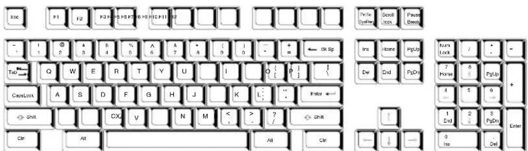
text_image
Esc F1 F2 F3 F4 F5 F6 F7 F8 F9 F10 F11 F12 Prise Systects Scroll Lock Pause Break - 1 2 3 4 5 6 7 8 9 0 - + ← On Sp Tab Q W E R T Y U I O [ P ] CausLock A S D F G H J K L: Enter Shift CX V N M < ? Shift Ctrl Alt All Ctrl Ins Home PgUp Del End PgDn Kurn Lock / ↑ - 7 Home 8 PgUp + 4 5 6 1 End 2 S PgDn Enter 0 Ins DelA 101-key enhanced keyboard layout
The keyboard is designed to provide all the features of the 101-key enhanced keyboard. The 101/102-key enhanced keyboard has a numeric keypad and scroll lock key. It also has additional Enter and Ctrl keys to the right of the main keyboard. Since the keyboard is smaller and has fewer keys, some of the enhanced keyboard functions must be simulated using two keys instead of one on the larger keyboard.
Your software may require you to use keys that the keyboard does not have. Pressing the Fn key and one of the following keys simulates the enhanced keyboard's functions.

text_image
Fn + F10 or Fn + F11Press Fn + F10 or Fn + F11 to access the integrated keypad. When activated, the keys with gray markings on the bottom edge become numeric keypad keys (Fn + F11) or cursor control keys (Fn + F10). Refer to the Keypad overlay section in this chapter for more information on how to operate these keys. The power on default for both settings is off.
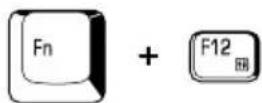
Press Fn + F12 (ScrLock) to lock the cursor on a specific line. The power on default is off.
Press Fn + Enter to simulate Enter on the enhanced keyboard's numeric keypad.
Press Fn + Ctrl to simulate the enhanced keyboard's right Ctrl key.
Hot keys
Hot keys (Fn + a function or Esc key) let you enable or disable certain features of the computer.
Sound mute: Pressing Fn + Esc in a Windows environment turns sound on or off. When you press these hot keys, the current setting will change and be displayed as an icon.
Instant security: Press Fn + F1 to blank the screen to prevent others from accessing your data. To restore the screen and original settings, press any key or press the Touch Pad. If a screensaver password is registered, a dialog box will appear. Enter the screensaver password and click OK. If no password is set, the screen will be restored when you press any key or press the Touch Pad.
Power save mode: Pressing Fn + F2 changes the power save mode. If you press Fn + F2 in a Windows environment, the settings dialog box for the Power Save Mode will be displayed. Continue holding down Fn, and release and press F2 again to toggle between the settings. Release both Fn and F2 to put the new setting into effect. You can also change this setting through the Profile options in TOSHIBA Power Saver.
Standby: When you press Fn + F3, the computer enters Standby Mode. Before entering Standby, a dialog box appears asking for your confirmation. This dialog box will not be displayed in the future if you click the check box.
Hibernation: When you press Fn + F4, the computer enters Hibernation Mode. Before entering Hibernation, a dialog box appears asking for your confirmation. This dialog box will not be displayed in the future if you click the check box.
Display selection: Press Fn + F5 to change the active display device. When you press these hot keys, a dialog box appears. Only selectable devices will be displayed. Hold down Fn and press F5 again to change the device. When you release Fn and F5, the selected device will change. If you hold down these hot keys for five seconds the selection will return to the internal LCD.
Internal LCD screen Brightness: Pressing Fn + F6 decreases the LCD screen brightness in decrements. When you press these hot keys, the current setting will be displayed for two seconds by an icon. You can also change this setting through the Screen brightness item of the Basic Setup tab in TOSHIBA Power Saver.
Internal LCD screen Brightness: Pressing Fn + F7 increases the LCD screen brightness in increments. When you press these hot keys, the current setting will be displayed for two seconds by a pop-up icon. You can also change this setting through the Screen brightness item of the Basic Setup tab in TOSHIBA Power Saver.

The brightness level is always set at the maximum value for about 18 seconds, when the internal LCD screen turns on.
LCD screen clarity increases with the brightness level.
Wireless setting: If your computer has both Bluetooth and Wireless LAN functions, you can press Fn + F8 to select which type of wireless communication you want to use. When you press these hot keys, a dialog box will appear. Continue holding down Fn and press F8 to change the setting. If wireless communication is turned off, Disabled Wireless Communication Switch will be displayed.

If no wireless communication device is installed, no dialog box will appear.
Touch Pad: Pressing Fn + F9 in a Windows environment enables or disables the Touch Pad function. When you press these hot keys, the current setting will change and be displayed as an icon.
LCD screen resolution selection: Press Fn + Space keys to change the display resolution. Each time when you press these hot keys, the LCD screen resolution changes as follows: The available resolution depends on the model. With XGA, you can change the resolution between 800 × 600 and 1024 × 768 pixels. With SXGA+, between 800 × 600 and 1400 × 1050 pixels.
Optical Drive Power: Press the Fn + Tab keys to turn the power of the optical media drive on or eject the disc tray. A dialog box is displayed when this hotkey is pressed. To choose between the functions, press the Tab key while holding down the Fn key. The chosen function is executed when the Fn + Tab keys are released.
TOSHIBA Zooming Utility (reduce): To reduce the icon size on the desktop or the application window, press the 1 key while holding down the Fn key.
TOSHIBA Zooming Utility (enlarge): To enlarge the icon size on the desktop or the application window, press the 2 key while holding down the Fn key.
Fn Sticky key
You can use the TOSHIBA Accessibility Utility to make the Fn key sticky, that is, you can press it once, release it, and then press an "F number" key. To start the TOSHIBA Accessibility Utility, click start, point to All Programs, point to TOSHIBA, point to Utilities and click Accessibility.
Windows special keys
The keyboard provides two keys that have special functions in Windows: Windows logo key activates the start menu and the other, the application key, has the same function as the secondary mouse button.

This key activates the Windows start menu.

This key has the same function as the secondary mouse button.
Keypad overlay
Your computer's keyboard does not have an independent numeric keypad, but its numeric keypad overlay functions like one.
The keys in the center of the keyboard with gray letters make up the numeric keypad overlay. The overlay provides the same functions as the numeric keypad on the 101/102-key enhanced keyboard.
Turning on the overlays
The numeric keypad overlay can be used for numeric data input or cursor and page control.
Arrow mode
To turn on the Arrow mode, press Fn + F10. The Arrow mode indicator lights. Now try cursor and page control using the keys.
Press Fn + F10 again to turn off the overlay.
Numeric mode
To turn on the Numeric mode, press Fn + F11. The Numeric mode indicator lights. Now try numeric data entry using the keys.
Press Fn + F11 again to turn off the overlay.
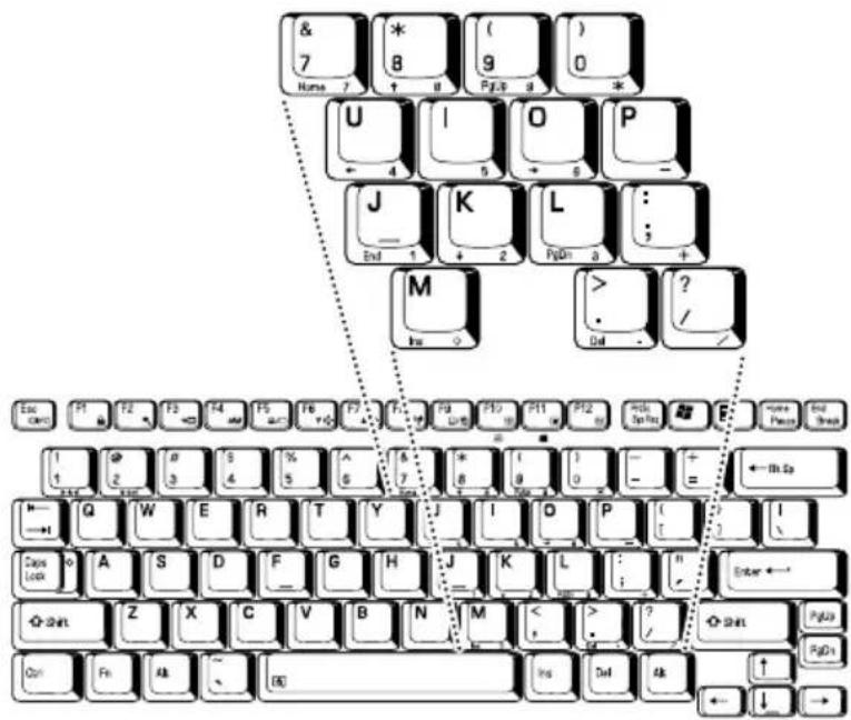
text_image
& 7 Home 7 * 8 ( ) 9 0 * U 4 I 5 O 6 P - J End 1 K + 2 L FgD1 3 : + M Ine > ? / Del ? Eo CNC F1 F2 F3 F4 F5 F6 F7 F8 F9 F10 F11 F12 F13 F1 F2 F3 F4 F5 F6 F7 F8 F9 F10 F11 F12 F13 F1 F2 F3 F4 F5 F6 F7 F8 F9 F10 F11 F12 F13 F1 F2 F3 F4 F5 F6 F7 F8 F9 F10 F11 F12 F13 F1 F2 F4 F5 F6 F7 F8 F9 F10 F11 F12 F13 F1 F2 F3 F4 F5 F6 F7 F8 F9 F10 F11 F12 F13 F1 F2 F3 F4 F5 F6 F7 F8 F9 F10 F11 F12 F13 F1 F2 F3 F4 F5 F6 F1 F2 F3 F4 F5 F6 F1 F2 F3 F4 F1 F2 F3 F1 F2 F3 F1 F2 F3 F1 F2 F3 F1 F2 F3 F1 F2 F3 F1 F2 F3 F1 F2 F3 F1 F2 F3 F1 F2 F3 F1 F2 F3 F1 F2 F3 F1 E W E R T Y J I O P [ ? Q W E R T Y J I O P [ ? C D S D G H J K L [ ? A S D E G H J K L [ ? Z X C V B N M < > D Shn Z X C V B N M < > D Shn Z X C V B N M < > D Shn Z X C V B N M < > D Shn Z X C V B N M < > D Shn Z X C V B N M < > D Shn Z X C V B N M < > D Shn Z X C V B N M < > D Shn Z X C V B N M < > D Shn Z X C V D Shn Z X C V B N M < > D Shn Z X C V B N M < > D Shn Z X C V B N M < > D Shn Z X C V B N M < > D Shn Z X C V B N M < > D Shn Z X C V B N M < > D Shn Z X C V B N M < > D Shn Z X C V B N M < > D ShnZ X C V B N M < > D ShnZ X C V B N M < > D ShnZ X C V B N M < > D ShnZ X C V B N M < > D ShnZ X C V B N M < > D ShnZ X C V B N M < > D ShnZ X C V B N M < > D ShnZ X C V B N M < > D ShnZ X C V D ShnZ X C V B N M < > D ShnZ X C V B N M < > D ShnZ X C V B N M < > D ShnZ X C V B N M < > D ShnZ X C V B N M < > D ShnZ X C V B N M < > D ShnZ X C V B N M < > D ShnZ X C V B N M < > D ShnT Z X C V B N M < > D ShnT Z X C V B N M < > D ShnT Z X C V B N M < > D ShnT Z X C V B N M < > D ShnT Z X C V B N M < > D ShnT Z X C V B N M < > D ShnT Z X C V B N MThe numeric keypad overlay
Temporarily using normal keyboard (overlay on)
While using the overlay, you can temporarily access the normal keyboard without turning off the overlay:
- Hold Fn and press any other key. All keys will operate as if the overlay was off.
- Type upper-case characters by holding Fn + Shift and pressing a character key.
- Release Fn to continue using the overlay.
Temporarily using overlay (overlay off)
While using the normal keyboard, you can temporarily use the keypad overlay without turning it on:
- Press and hold down Fn.
- Check the keyboard indicators. Pressing Fn turns on the most recently used overlay. If the Numeric mode indicator lights, you can use the overlay for numeric entry. If the Arrow mode indicator lights, you can use the overlay for cursor and page control.
- Release Fn to return to normal keyboard operation.
Temporarily changing modes
If the computer is in Numeric mode, you can switch temporarily to Arrow mode by pressing a shift key.
If the computer is in Arrow mode, you can switch temporarily to Numeric mode by pressing a shift key.
Generating ASCII characters
Not all ASCII characters can be generated using normal keyboard operation. But, you can generate these characters using their ASCII codes.
With the overlay on:
- Hold down Alt.
- Using the overlay keys, type the ASCII code.
- Release Alt, and the ASCII character appears on the display screen.
With the overlay off:
- Hold down Alt + Fn.
- Using the overlay keys, type the ASCII code.
- Release Alt + Fn, and the ASCII character appears on the display screen.
Chapter 6
Power and Power-Up Modes
The computer's power resources include the AC adaptor, battery pack and internal batteries. This chapter gives details on making the most effective use of these resources including charging and changing batteries, tips for saving battery power, and power up modes.
Power conditions
The computer's operating capability and battery charge status are affected by the power conditions: whether an AC adaptor is connected, whether a battery pack is installed and what the charge level is for the battery.
Power conditions
| Power on | Power off (no operation) | ||
| AC adaptor connected | Main Battery fully charged | OperatesNo chargeLED:Battery greenDC IN green | No chargeLED:Battery greenDC IN green |
| Main Battery partially charged or no charge | OperatesCharge*LED:Battery orangeDC IN green | Quick charge*LED:Battery orangeDC IN green | |
| No Main battery installed | OperatesNo chargeLED:Battery offDC IN green | No chargeLED:Battery offDC IN green | |
| AC adaptor connected | Secondary battery fully charged | OperatesNo chargeLED: Secondary battery greenDC IN green | No chargeLED: Secondary battery greenDC IN green |
| Secondary battery partially charged or no charge | OperatesCharge*2LED: Secondary battery orangeDC IN green | Quick charge*2LED: Secondary battery orangeDC IN green | |
| No Secondary battery installed | OperatesNo chargeLED: Secondary battery offDC IN green | No chargeLED: Secondary battery offDC IN green | |
| AC adaptor not connected | Main battery charge is above low battery trigger point | OperatesLED: Battery offDC IN off | |
| Main battery charge is below low battery trigger point | OperatesLED: Battery flashes orangeDC IN off | ||
| Main battery charge is exhausted | Computer shuts down * | ||
| No main battery installed | No operation *LED: Battery offDC IN off | ||
| AC adaptor not connected | Secondary battery charge is above low battery trigger point | OperatesLED: Secondary battery offDC IN off | |
| Secondary battery charge is below low battery trigger point | OperatesLED: Secondary battery flashes orangeDC IN off | ||
| Secondary battery charge is exhausted | Computer shuts down *3 | ||
| No Secondary battery is installed | No operation *5LED: Secondary battery offDC IN off | ||
*1 When the Slice Expansion battery is not charging.
^*2 When the main battery is not charging.
*3 For the computer to shut down in hibernation mode, the hibernation feature must be enabled in two places in TOSHIBA Power Saver: the Hibernate window and the Battery Alarm item of the Alarm window. If a main battery and a Slice Expansion battery are installed, the computer does not shut down until the charge in both batteries is exhausted.
*4 When no Slice Expansion battery is installed.
*5 When no main battery is installed.

When batteries are charged, the main battery is charged first. When it is fully charged, the Slice Expansion battery is charged.
Power indicators
As shown in the above table, the Battery, Secondary battery, DC IN and Power indicators on the system indicator alert you to the computer's operating capability and battery charge status.
Battery indicator
Check the Battery indicator to determine the status of the main battery and the Secondary battery indicator to determine the status of the Slice Expansion battery. The following indicator lights indicate the battery status:
| Flashing orange | The battery charge is low. The AC adaptor must be connected to recharge the battery. |
| Orange | Indicates the AC adaptor is connected and charging the battery. |
| Green | Indicates the AC adaptor is connected and the battery is fully charged. |
| No light | Under any other conditions, the indicator does not light. |

If the battery pack becomes too hot while it is being charged, the charge will stop and the Battery indicator will go out. When the battery pack's temperature falls to a normal range, charge will resume. This occurs whether the computer's power is on or off.
DC IN indicator
Check the DC IN indicator to determine the power status with the AC adaptor connected:
| Green | Indicates the AC adaptor is connected and supplying proper power to the computer. |
| Flashing orange | Indicates a problem with the power supply. Plug the AC adaptor into another power outlet. If it still does not operate properly, contact your dealer. |
| No light | Under any other conditions, the indicator does not light. |
Power indicator
Check the Power indicator to determine the power status:
| Green | Indicates power is being supplied to the computer and the computer is turned on. |
| Flashing orange | Indicates power is being supplied to the computer while the computer is in Standby Mode. The indicator turns on for one second and off for two seconds. |
| No light | Under any other conditions, the indicator does not light. |
Battery types
The computer has three types of batteries:
Battery pack
■Slice Expansion Battery (optional)
Real Time Clock (RTC) battery
Battery pack
When the AC adaptor is not connected, the computer's main power source is a removable lithium ion battery pack, also referred to in this manual as the main battery. You can purchase additional battery packs for extended use of the computer away from an AC power source.
Do not change the battery pack while the AC adaptor is connected.
Before you remove the battery pack, save your data and shut down the computer, or set the computer to Hibernation Mode. While entering Hibernation Mode, the computer saves the contents of memory to the hard disk drive. However, for safety sake, it is best to save your data manually.

The battery pack is a lithium ion battery, which can explode if not properly replaced, used, handled or disposed of. Dispose of the battery as required by local ordinances or regulations. Use only batteries recommended by TOSHIBA as replacements.
■Always use the battery pack supplied as an accessory or an equivalent Always use the battery pack supplied as an accessory or an equivalent battery pack specified in the User's Manual. Other battery packs have different voltage and terminal polarities. Use of non-conforming battery packs could generate smoke or cause fire or rupture, possibly resulting in serious injury.
Always dispose of used battery packs in compliance with all applicable laws and regulations. Put insulating tape, such as cellophane tape, on the electrode during transportation to avoid a possible short circuit, fire or electric shock. Failure to do so could possibly result in serious injury.
Do not remove the battery pack while the computer is in Standby Mode. Data is stored in RAM, so if the computer loses power it will be lost. When the computer is powered off in Standby Mode, and the AC adaptor is not connected, the battery pack supplies power to maintain data and programs in memory. If the battery pack is completely discharged, Standby Mode will not function and the computer loses all data in memory.
To ensure that the battery pack maintains its maximum capacity, operate the computer on battery power at least once a month until the battery pack is fully discharged. Refer to Extending battery life in this chapter for procedures. If the computer is continuously operated on AC power through an AC adaptor for an extended period, more than a month, the battery may fail to retain a charge. It may not function efficiently over the expected life of the battery and the Battery indicator may not indicate a low-battery condition.
Slice Expansion Battery (optional)
The Slice Expansion Battery is included with some models, or can be purchased separately as an optional accessory.
For detailed information on this battery, refer to Slice Expansion Battery section in Chapter 8.

The Slice Expansion Battery is a lithium ion battery, which can explode if not properly replaced, used, handled or disposed of. Dispose of the battery as required by local ordinances or regulations. Use only batteries recommended by TOSHIBA as replacements.
Real Time Clock (RTC) battery
The Real Time Clock (RTC) battery provides power for the internal real time clock and calendar. It also maintains the system configuration.
If the RTC battery becomes completely discharged, the system loses this data and the real time clock and calendar stop working. The following message appears when you turn on the power:

**** RTC battery is low or CMOS checksum is inconsistent ****
Press [F1] key to set Date/Time.
You can change the Real Time Clock settings by pressing the F1 key. Refer to Chapter 9 Troubleshooting, for details.

The computer's RTC battery is a Ni-MH battery and should be replaced only by your dealer or by a TOSHIBA service representative. The battery can explode if not properly replaced, used, handled or disposed of.
Dispose of the battery as required by local ordinances or regulations.
Care and use of the battery pack
The battery pack is a vital component of portable computing. Taking proper care of it will help ensure longer operating time on battery power as well as a longer life for your battery pack. Follow the instructions in this section carefully to ensure safe operation and maximum performance.
Safety precautions
Mishandling of battery packs can cause death, serious injury or property damage. Carefully observe the following advisories:
Warning: Indicates a potentially hazardous situation, which could result in death or serious injury, if you do not follow instructions.
Caution: Indicates a potentially hazardous situation, which if not avoided, may result in moderate or minor injury or property damage.
Note: Provides important information.
Warning
-
Never attempt to dispose of a battery pack by burning or by throwing it into a fire, and never allow exposure to a heating apparatus (e.g., microwave oven). Heat can cause a battery pack to explode and possibly cause serious injury.
-
Never attempt to disassemble, tamper with or repair a battery pack. The battery pack could overheat and ignite. Leakage of the caustic alkaline solution or other electrolytic substances could cause fire, possibly resulting in death or serious injury.
-
Never short circuit the battery pack by either accidentally or intentionally bringing the battery terminals in contact with another conductive object. This could cause serious injury or a fire, and could also damage the battery pack. Always wrap the battery pack in plastic (or place it in a plastic bag) whenever transporting it, to avoid exposing the terminals to another conductive object which could result in serious injury. Always cover the metal terminals with insulating tape when disposing of the battery pack, to prevent accidental short circuiting which could result in serious injury.
-
Never drive a nail or any other sharp object into the battery pack, hit battery pack with a hammer or other object or step on it. Doing so could cause a fire or explosion possibly resulting in serious injury.
-
Never charge the battery pack by a method other than as instructed in the User's Manual. Doing so could cause a fire or explosion possibly resulting in serious injury.
-
Never connect the battery pack to a plug socket or a car cigarette plug socket. The battery pack could rupture or ignite causing a fire or explosion possibly resulting in serious injury.
-
Never allow a battery pack to become wet. A wet battery pack will overheat or ignite causing rupture or fire, possibly resulting in death or serious injury.
-
Never store a battery pack in an area of high humidity. This could cause a fire or explosion possibly resulting in serious injury.
-
Never expose a battery pack to abnormal shock, vibration or pressure. The battery pack's internal protective device could fail, causing it to overheat or ignite resulting in caustic liquid leakage, or explosion or fire, possibly resulting in death or serious injury.
-
Never subject a battery pack to heat, and never store it or use it near a heat source. The battery pack could ignite or explode when heated or burned, possibly resulting in death or serious injury. Subjecting a battery pack to heat could also cause caustic liquid to leak. It can also cause failure, malfunction, or loss of stored data.
-
Always use the battery pack supplied as an accessory or an equivalent battery pack specified in the User's Manual. Other battery packs have different voltage and terminal polarities. Use of non-conforming battery packs could generate smoke or cause fire or rupture, possibly resulting in serious injury.
-
Never allow caustic electrolyte fluid leaked from the battery pack to contact your eyes, body or clothing. If caustic electrolyte fluid from the battery pack should contact your eyes, immediately wash your eyes with large amounts of running water and obtain prompt medical attention, to help prevent permanent eye damage. If electrolyte fluid should contact any part of your body, immediately wash it off under running water to help prevent skin rashes. If electrolyte fluid should contact your clothes, promptly remove them to help prevent the electrolyte fluid from contacting your body, possibly resulting in serious injury.
-
Always immediately turn the power off and disconnect the power cable plug from the plug socket if you observe any of the following conditions:
■Offensive or unusual odor
Excessive heat
Discoloration
Deformation
Smoke
■Other unusual event during use, such as abnormal sound
In such an event, immediately remove the battery pack from the PC. In some instances, you might have to wait for the PC to cool down before removing the battery pack, in order to avoid any possible minor injury due to heat exposure. Do not turn on the PC's power again until an authorized Toshiba service provider has checked it for safety.
Continued use could cause a fire or rupture possibly resulting in serious injury or PC failure including but not limited to the loss of data.
- Always dispose of used battery packs in compliance with all applicable laws and regulations. Put insulating tape, such as cellophane tape, on the electrode during transportation to avoid a possible short circuit, fire or electric shock. Failure to do so could possibly result in serious injury.
- Make sure the battery is securely installed in the computer before attempting to charge the battery pack. Improper installation could generate smoke or fire, or cause the battery pack to rupture.
- Keep the battery pack out of reach of infants and children. It can cause injury.
Caution
- Use only battery packs recommended by TOSHIBA as replacements.
- When installing a battery pack or before moving the PC, always make sure the battery pack is inserted correctly and securely. If the battery falls out, while you are carrying the PC, you could be injured or the battery pack could be damaged.
- Charge the battery pack only in an ambient temperature between 5 and 35 degrees Celsius. Otherwise, the electrolyte solution might leak, battery pack performance might deteriorate and the battery life might be shortened.
- Never continue to use a battery pack after its recharging capability has become impaired, or after the warning message indicating that the battery pack power is exhausted has been displayed.
- Continued use of an exhausted or impaired battery pack could result in the loss of data or damage to PC.
- Never install or remove the battery pack without first turning off the power and disconnecting the AC adaptor. Never remove the battery pack while the computer is in Standby Mode. Data will be lost.
Note
- Never remove the battery pack while the Wake-up on LAN function is enabled. Data will be lost. Before you remove a battery pack, disable the Wake-up on LAN function.
- Never remove the battery pack while the Wake-up on Wireless LAN function is enabled. Data will be lost. Before you remove a battery pack, disable the Wake-up on Wireless LAN function.
- To ensure the battery pack maintains maximum capacity, operate the computer on battery power once a week until the battery pack is fully discharged. Refer to the section Extending battery life in this chapter for procedures. If the computer is continuously operated on AC power for an extended period, more than a week, the battery might fail to retain a charge. It might not function efficiently over the expected life of the battery pack and the Battery indicator might not indicate a low-battery condition.
- After the battery pack is charged, avoid leaving the AC adaptor connected and the computer turned off for more than a few hours at a time. Continuing to charge a fully-charged battery pack can damage the battery.
Charging the batteries
When the power in the battery pack becomes low, the Battery indicator flashes orange indicating that only a few minutes of battery power remain. If you continue to use the computer while the Battery indicator flashes, the computer enables Hibernation Mode (so you don't lose data) and automatically turns off.

The computer enters Hibernate mode only if Hibernation is enabled in two places: the Hibernate tab in Power Options and Setup Actions tab in TOSHIBA Power Saver.
You must recharge a battery pack when it becomes discharged.
Procedures
To recharge a battery pack while it is installed in the computer, connect the AC adaptor to the DC IN 15V jack and plug the other end into a working outlet.
The Battery indicator glows orange when the battery is being charged.

Use only the computer connected to an AC power source or the optional TOSHIBA Battery charger to charge the battery pack. Never attempt to charge the battery pack with any other charger.
Time
The following table shows the approximate time required to fully charge a discharged battery.
Charging time (hours)
| Battery type Power on Power off |
| Battery pack (4700mAh) about 3.0 to 13.0 about 3.0 |
| Slice Expansion Battery (4000mAh) about 3.0 to 10.5 about 3.0 |
| RTC battery 8 Doesn't charge |

The charging time when the computer is on is affected by ambient temperature, the temperature of the computer and how you use the computer. If you make heavy use of external devices, for example, the battery might scarcely charge at all during operation. Refer also to the section Maximizing battery operating time.
Battery charging notice
The battery may not charge right away under the following conditions:
The battery is extremely hot or cold. If the battery is extremely hot, it might not charge at all. To ensure the battery charges to its full capacity, charge the battery at room temperature of 10^ to 30^ C ( 50^ to 88^ F).
The battery is nearly completely discharged. Leave the AC adaptor connected for a few minutes and the battery should begin charging.
The Battery indicator may show a rapid decrease in battery operating time when you try to charge a battery under the following conditions:
■The battery has not been used for a long time.
■The battery has completely discharged and been left in the computer for a long time.
■A cool battery is installed in a warm computer.
In such case, follow the steps below.
- Fully discharge the battery by leaving it in the computer with the power on until the power automatically shuts off.
- Connect the AC adaptor to the DC IN 15V jack of the computer, and the AC adaptor into power outlet.
- Charge the battery until the Battery indicator glows green.
Repeat these steps two or three times until the battery recovers normal capacity.

Leaving the AC adaptor connected will shorten battery life. At least once a month, run the computer on battery power until the battery is fully discharged, then recharge the battery.
Monitoring battery capacity
Remaining battery power can be monitored in TOSHIBA Power Saver.

- Wait at least 16 seconds after turning on the computer before trying to monitor the remaining operating time. The computer needs this time to check the battery's remaining capacity and to calculate the remaining operating time, based on the current power consumption rate and remaining battery capacity. The actual remaining operating time may differ slightly from the calculated time.
With repeated discharges and recharges, the battery's capacity will gradually decrease. Therefore, an often used, older battery will not operate for as long as a new battery even when both are fully charged. In this case, TOSHIBA Power Saver will indicate a 100% charge for both the old and new battery, but the displayed estimated time remaining will be shorter for the older battery.
Maximizing battery operating time
A battery's usefulness depends on how long it can supply power on a single charge.
How long the charge lasts in a battery depends on:
■How you configure the computer (for example, whether you enable battery-power saving options). The computer provides a battery save mode, which can be set in TOSHIBA Power Saver, to conserve battery power. This mode has the following options:
■CPU Processing speed
Screen brightness
Cooling Method
System standby
System Hibernation
■Monitor Power off
■HDD Power off
How often and how long you use the hard disk, optical disc and the floppy disk drive.
■How much charge the battery contained to begin with.
■How you use optional devices, such as a PC card, to which the battery supplies power.
■ Enabling Standby Mode conserves battery power if you are frequently turning the computer off and on.
■Where you store your programs and data.
■Closing the LCD display panel when you are not using the keyboard saves power.
■Operating time decreases at low temperatures.
The condition of the battery terminals. Make sure the battery terminals stay clean by wiping them with a clean dry cloth before installing the battery pack.
Retaining data with power off
When you turn off your computer with fully charged batteries, the batteries retain data for the following approximate time periods:
Retention time
| Battery type State and Retention Time | |
| Battery pack (4700mAh) | about 6 days (Standby mode)about 70 days (Boot mode) |
| Slice Expansion Battery (4000mAh) | about 5 days (Standby mode)about 60 days (Boot mode) |
| RTC battery | 30 days |
Extending battery life
To maximize the life of your battery pack:
At least once a month, disconnect the computer from a power source and operate it on battery power until the battery pack fully discharges. Before doing so, follow the steps below.
- Turn off the computer's power.
- Disconnect the AC adaptor and turn on the computer's power. If it does not turn on go to step 4.
- Operate the computer on battery power for five minutes. If the battery pack has at least five minutes of operating time, continue operating until the battery pack is fully discharged. If the Battery indicator flashes or there is some other warning to indicate a low battery, go to step 4.
- Connect the AC adaptor to the computer and the power cord to a power outlet. The DC IN indicator should glow green, and the Battery indicator should glow orange to indicate that the battery pack is being charged. If the DC IN indicator does not glow, power is not being supplied. Check the connections for the AC adaptor and power cord.
- Charge the battery pack until the Battery indicator glows green.
■If you have extra battery packs, rotate their use.
If you will not be using the system for an extended period, more than one month, remove the battery pack..
■ Disconnect the AC adaptor when the battery is fully charged. Overcharging makes the battery hot and shortens life.
If you are not going to use the computer for more than eight hours, disconnect the AC adaptor.
■ Store spare battery packs in a cool dry place out of direct sunlight.
Replacing the battery pack
The battery pack is classified as a consumable item.
The operating life of the battery pack will gradually reduce through repeated charging and discharging. It will need to be replaced when it reaches the end of its operating life.
You might also replace a discharged battery pack with a charged spare when you are operating your computer away from an AC power source. This section explains how to remove and install the battery pack.
To remove a discharged battery pack, follow the steps below.

Do not remove the battery pack while the computer is in Standby Mode. Data is stored in RAM, so if the computer loses power it will be lost.
In Hibernation Mode, data will be lost if you remove the battery pack or disconnect the AC adaptor before the save is completed. Wait for the HDD indicator to go out.
Do not touch the battery release latch while holding the computer or the battery pack might fall out due to the unintentional release of the battery release latch and cause injuries.
- Save your work.
- Turn the computer's power off. Make sure the Power indicator is off.
- Remove all cables connected to the computer.
- Close the LCD display panel and turn the computer upside down.
- Slide the battery safety lock towards the release ( ) position to make the battery release latch movable.
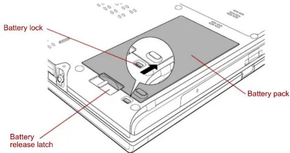
text_image
Battery lock Battery pack Battery release latchReleasing the battery pack (1)
- Slide the battery release latch to free the battery pack for removal, then slide out the battery pack.
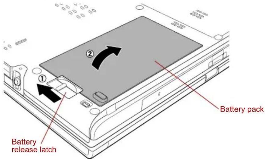
text_image
Battery release latch Battery packReleasing the battery pack (2)
To install a battery pack, follow the steps below.

Do not touch the battery release latch while holding the computer. Or you may get injured by the dropped battery pack by unintentional release of the battery release latch.
- Insert the battery pack.
- Make sure that the battery pack is securely in place and the battery safety lock is in the lock position (☐)
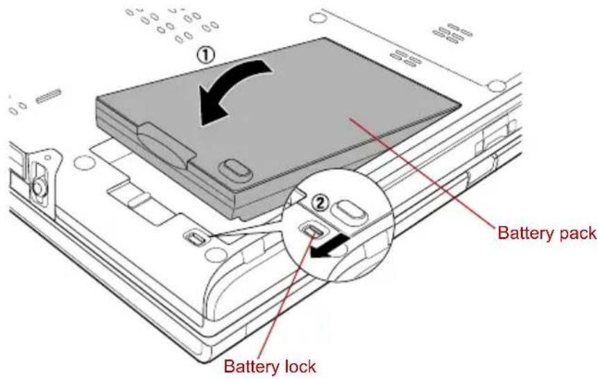
text_image
Battery lock Battery packSecuring the battery pack
- Return your computer to the upright position.
TOSHIBA Password Utility
The TOSHIBA Password Utility provides two levels of password security: User and Supervisor.

Passwords set in the TOSHIBA Password Utility are different from the Windows password.
User Password
To start the utility, point to or click the following items:
start -> All Programs -> TOSHIBA -> Utilities ->Password Utility
The User Password dialog box contains two main fields: User
Password and User Token.
User authentication may be required to validate user rights when using "TOSHIBA Password Utility" to delete or change passwords, or create tokens, etc.
User Password field
Set (button)
Click this button to register a password of up to 50 characters. After a password is set, you will be prompted to enter it when you start the computer. Check "Set the same string simultaneously as HDD User Password" when setting the HDD User Password.

■After you set the password, a dialog box will be displayed asking whether you want to save it to a floppy disk or other media. If you forget the password, you can open the password file on another computer. Be sure to keep the media in a safe place.
When entering the character string to register the password, enter from the keyboard character by character and do not enter as ASCII code or copy-and-paste the character string. In addition, ensure that the registered password is correct by outputting the character string to the password file.
Delete (button)
Click this button to delete a registered password. Before you can delete a password, you must first enter the current password correctly or insert a proper token. Please use BIOS Setup to change or delete the HDD Passwords or to set the HDD Master Password.
Change (button)
Click this button to change a registered password. Before you can change a password, you must first enter the current password correctly or insert a proper token. Please use BIOS Setup to change or delete the HDD Passwords or to set the HDD Master Password.
■Owner String (text box)
You can use this box to associate text with the password. After you enter text, click Apply or OK. When the computer is started, this text will be displayed together with the prompt asking you to enter a password.

If you forget your HDD User Password, TOSHIBA will NOT be able to assist you, and your HDD will be rendered COMPLETELY and PERMANENTLY INOPERABLE. TOSHIBA will NOT be held responsible for any loss of any data, any loss of use or access to your HDD, or for any other losses to you or any other person or organization that result from the loss of access to your HDD. If you can't accept this risk, don't register the HDD User Password.
When setting the HDD Master Password or the password for the Ultra Slim Bay HDD, save the HDD User Password settings in the BIOS SETUP Program.

When saving the HDD User Password shut down or restart the computer. If the computer is not shut down or restarted, the saved data may not be correctly reflected. For more information on shutting down or restarting the computer, refer to Turning on the power in Chapter 3.

Refer to Starting and Ending the BIOS Setup Program section in Chapter 7 for more information.
User Token field
■Create (button)
You can use an SD card token, instead of entering the password. After you have registered a password, insert an SD card in SD card slot and click Create. You can use an SD card of any capacity, but it must be formatted correctly.
If an unformatted card or one with an incompatible format is inserted, you will be prompted to format it with a tool named TOSHIBA SD Memory Card Format. To start the format tool, point to or click the following items:
start -> All Programs -> TOSHIBA -> Utilities -> SD Memory Card Format

When you format an SD Memory card, all data will be deleted. Be sure to save data on the card to other media before you format the card.
■Disable (button)
Click this button to invalidate the token. You cannot re-validate old tokens, but you can use the same SD cards to create new tokens.

After using the token created for authentication, do not leave it inserted in the SD card slot, ensure that the token is removed from the slot and stored in a safe location. If the token is left in the slot, there is a danger of theft or a third party using it for authentication and operating the user's computer (resulting in extraction, modification or deletion of data) when the user is not at their desk.
Supervisor Password
If you set a Supervisor Password, some functions might be restricted when a user logs on with the User Password. To set a Supervisor Password, execute the file TOSPU.EXE. The file is located at:
C:\Program Files\Toshiba\Windows Utilities\SVPWTool\TOSPU.EXE
This utility lets you do the following:
Register, delete or change the Supervisor Password.
■Create or invalidate a Supervisor Password token.

This function in the TOSHIBA Password Utility lets you invalidate only supervisor tokens or all tokens, including user and supervisor tokens.
■Specify restrictions for general users.
Starting the computer by password
If you have already registered a password, there are three ways to start the computer:
■Insert an SD card token before you turn on the computer. The computer will start normally, without displaying a password prompt.
■Swipe your fingerprint on the sensor if you have already registered the fingerprint with the Fingerprint utility and enabled Fingerprint System Boot Authentication. If you would not like to swipe your finger or cannot authenticate the fingerprint for some reasons, push the BkSp key to skip the fingerprint authentication screen. You can try to swipe the fingerprint up to five times. If you failed fingerprint authentication more than five times, you must enter the password manually to start the computer.
■Please log on with the Tablet PC Pen when in Tablet mode. Refer to Tablet mode section in this chapter.
■Enter the password manually.

The password is necessary only if the computer was shut down in boot mode. It is not needed in Standby Mode.
To enter a password manually, follow these steps:
- Turn on the power as described in Chapter 3, Getting Started. The following message will appear in the LCD:
- Enter the Password.
- Press Enter.

If you enter the password incorrectly three times in a row, the computer shuts off. In this case, you must turn the computer back on to retry password entry.
Tablet mode
Enter your password by tapping the on-screen keyboard using the Tablet PC Pen.
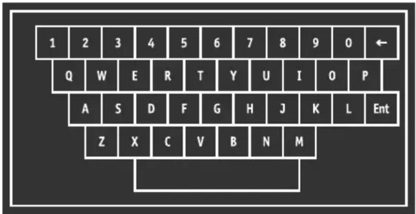
text_image
1 2 3 4 5 6 7 8 9 0 ← Q W E R T Y U I O P A S D F G H J K L Ent Z X C V B N MOn-screen keyboard
The beep sounds when tapping the on-screen keyboard with the Tablet PC Pen. An * (asterisk) is displayed after "Password=" and one character is input for every tapping.

Register your password to the computer in the laptop mode using the standard keyboard. Refer to TOSHIBA Password Utility, in this chapter for the detail.
Power-up modes
The computer has the following power-up modes:
■ Boot: Computer shuts down without saving data. Always save your work before you turn the computer off in boot mode.
■Hibernation: Data in memory is saved to the hard disk drive.
■Standby: Data is maintained in the computer's memory.

Refer also to the sections Turning on the power and Turning on the power in Chapter 3, Getting Started.
Windows utilities
You can configure various settings associated with both Standby Mode and Hibernation Mode within TOSHIBA Power Saver.
Hot keys
You can use hot keys Fn + F3 to enter Standby Mode and Fn + F4 to enter Hibernation. Refer to Chapter 5, The Keyboard, for details.
Panel power on/off
You can set up your computer so that power turns off automatically when you close the display panel. When you open the panel, power will be turned on in Standby Mode or Hibernation Mode but not in boot mode.

If the panel power off function is enabled and you manually shut down Windows, do not close the computer's LCD display panel until the shut down process has been completed.
System Auto Off
This feature turns the system off automatically if it is not used for a set duration. The system shuts down in Standby Mode or Hibernation Mode in Windows.
Chapter 7
HW Setup
This chapter explains how to use TOSHIBA HW Setup program to configure your computer, and provides information on setting up the Execute-Disable Bit Capability and TPM.
Accessing HW Setup
To run HW Setup, click start, click Control Panel, click Printers and Other Hardware and select TOSHIBA HWSetup.
HW Setup window
The HW Setup window contains the following tabs: General, Display, Boot Priority, Keyboard, CPU, LAN, Device Config and USB.
There are also three buttons: OK, Cancel and Apply.
| OK | Accepts your changes and closes the HW Setup window. |
| Cancel | Closes the window without accepting your changes. |
| Apply | Accepts all your changes without closing the HW Setup window. |
General
This window displays the BIOS version and contains two buttons: Default and About.
| Default | Return all HW Setup values to the factory settings. |
| About | Display the HW Setup version. |
Setup
This field displays BIOS Version and date.
Display
This tab lets you customize your computer's display settings for either the internal LCD screen or an external monitor.
Power On Display
Lets you select the display to be used when the computer is booted (This setting is only available on Standard VGA mode and is not available on Windows Desktop properties).
| Auto-Selected | Selects an external monitor if one is connected. Otherwise, it selects the internal LCD (Default). |
| LCD + Analog RGB | Selects both the internal LCD and external monitor for simultaneous display. |
| System LCD Only | Selects the internal LCD even if the external monitor is connected. |

If the connected external monitor does not support the computer's current video mode, selecting the LCD + Analog RGB mode will not display any image on the external monitor.
When Windows starts up, the screen will be displayed on the external monitor if it was connected when the notebook was previously switched off and is still connected when the computer is switched on. Otherwise, the screen will be displayed on the internal LCD.
Boot Priority
Boot Priority Options
This option sets the priority for booting the computer. Select from the following settings:
| HDD -> FDD -> CD-ROM -> LAN | The computer looks for bootable files in the following order: HDD, floppy disk drive*1, CD-ROM*2 and LAN (Default). |
| FDD -> HDD -> CD-ROM -> LAN | The computer looks for bootable files in the following order: floppy disk drive*1, HDD, CD-ROM*2 and LAN. |
| HDD -> CD-ROM -> LAN -> FDD | The computer looks for bootable files in the following order: HDD, CD-ROM*2, LAN and floppy disk drive*1. |
| FDD -> CD-ROM -> LAN -> HDD | The computer looks for bootable files in the following order: floppy disk drive*1, CD-ROM*2, LAN and HDD. |
| CD-ROM -> LAN -> HDD -> FDD | The computer looks for bootable files in the following order: CD-ROM*2, LAN, HDD, floppy disk drive*1. |
| CD-ROM -> LAN -> FDD -> HDD | The computer looks for bootable files in the following order: CD-ROM*2, LAN, floppy disk drive*1 and HDD. |
You can override the settings and manually select a boot device by pressing one of the following keys while the computer is booting:
U Selects the USB floppy disk drive.
N Selects the network.
1 Selects the primary HDD.
2 Selects the secondary HDD.
C Selects the CD-ROM ^* 2.
M Selects the USB Memory.
To change the boot drive, follow the steps below.
- Hold down F12 and boot the computer.
- The following menu will be displayed with the following icons: Built-in HDD, Ultra Slim Bay HDD, CD-ROM, FDD (or SD memory card), Network (LAN), USB Memory boot.


A bar will appear only under the selected device.
- Use the left/right cursor keys to highlight the boot device you want and press Enter.

If only a Supervisor Password has been set, the following should be noted:
The boot device menu will appear when the 'Able to run HW Setup' option has been configured.
The boot device menu will not appear when the 'Unable to run HW Setup' option has been configured.
If both a Supervisor Password and a User Password are set, the following should be noted:
The boot device menu will appear when you use either the Supervisor Password or the User Password to start the computer, and the 'Able to run HW Setup' option has been configured.
The boot device menu will not appear when you use the User Password to start the computer and the 'Unable to run HW Setup' option has been configured.
The boot device menu will appear when you use the Supervisor Password to start the computer, even if the 'Unable to run HW Setup' option has been configured.
The boot device selection methods described above will not change the boot priority settings that have been configured in HW Setup. In addition, if you press a key other than one of those listed, or if the selected device is not installed, the system will continue to boot according to the current and available settings in HW Setup.
HDD Priority Options
If more than one HDD is installed in the computer, this option lets you set the priority for HDD detection. If the first detected HDD has a boot command, the system will boot from the HDD.
| Built-in HDD 1 -> Built-in HDD 2 -> USB (Default) | The priority is set as Built-in HDD 1 -> Built-in HDD 2 -> USB. |
| Built-in HDD 2 -> Built-in HDD 1 -> USB | The priority is set as Built-in HDD 2 -> Built-in HDD 1 -> USB. |
| Built-in HDD 1 -> USB -> Built-in HDD 2 | The priority is set as Built-in HDD 1 -> USB -> Built-in HDD 2. |
| Built-in HDD 2 -> USB -> Built-in HDD 1 | The priority is set as Built-in HDD 2 -> USB -> Built-in HDD 1. |
| USB -> Built-in HDD 1 -> Built-in HDD 2 | The priority is set as USB -> Built-in HDD 1 -> Built-in HDD 2. |
| USB -> Built-in HDD 2 -> Built-in HDD 1 | The priority is set as USB -> Built-in HDD 2 -> Built-in HDD 1. |

If a boot command is not found on the first detected HDD, the system will not boot from the other HDD. It will search the next device in the boot priority for a boot command.
■ Some modules may not be displayed.
Network Boot Protocol
This feature sets the protocol to remotely boot from the network.

Network Boot Protocol is not displayed for Gigabit Ethernet LAN.
[PXE] Sets PXE as the protocol (Default).
[RPL] Sets RPL as the protocol.
USB Memory BIOS Support Type
Set the type of the USB memory as a startup device.
| HDD | Set the type of the USB memory to be equivalent to the HDD (Default).* Based on the [HDD] order in the [Boot Priority Options] item. The order with respect to the other HDD can be set in the [HDD Priority Options] item. |
| FDD | Set the type of the USB memory to be equivalent to the FDD.* Based on the [FDD] order in the [Boot Priority Options] item. |
Keyboard
Wake-up on Keyboard
When this feature is enabled and the computer is in Standby mode, you can turn on the computer by pressing any key. It is effective only for the internal keyboard and only when the computer is in Standby mode.
| Enabled | Enables the Wake-up on Keyboard function. |
| Disabled | Disables the Wake-up on Keyboard function (Default). |
CPU
This function lets you set the CPU operating mode.
This option is displayed only for models with an Intel ^® Core ^TM Duo processor and Intel ^® Core ^TM Solo processor.
Dynamic CPU Frequency Mode
This option lets you choose from the following settings:
| Dynamically Switchable | CPU power consumption and clock speed automatic switching function is enabled. When the computer is in use, CPU operation is automatically switched when necessary (Default). |
| Always High | CPU power consumption and clock speed automatic switching function is disabled. The CPU always runs at its fastest speed. |
| Always Low | CPU power consumption and clock speed automatic switching function is disabled. The CPU always runs at low power consumption and low speed. |

LAN
Wake-up on LAN
This feature lets the computer's power be turned on when it receives a wake-up signal from the LAN.
| Enabled | Enables Wake-up on LAN. |
| Disabled | Disables Wake-up on LAN (Default). |

Do not install or remove an optional memory module while Wake-up on LAN is enabled.

The Wake-up on LAN function consumes power even when the system is off. Leave the AC adaptor connected while using this feature.
Built-in LAN
This feature enables or disables the Built-in LAN.
| Enabled | Enables Built-in LAN functions (Default). |
| Disabled | Disables Built-in LAN functions. |
Device Config
Device Configuration
This option lets you set the device configuration.
| All Devices | BIOS sets all devices. |
| Setup by OS | Operating system sets devices that it can control (Default). |
USB
USB KB/Mouse Legacy Emulation
Use this option to enable or disable USB keyboard/mouse legacy emulation. If your operating system does not support USB, you can still use a USB mouse and keyboard by setting the USB KB/Mouse Legacy Emulation item to Enabled.
| Enabled | Enables the USB KB/Mouse Legacy Emulation function (Default). |
| Disabled | Disables the USB KB/Mouse Legacy Emulation function. |
USB-FDD Legacy Emulation
Use this option to enable or disable USB floppy disk drive legacy emulation. If your operating system does not support USB, you can still use a USB floppy disk drive by setting the USB-FDD Legacy Emulation item to Enabled.
| Enabled | Enables the USB floppy disk drive legacy emulation function (Default). |
| Disabled | Disables the USB floppy disk drive legacy emulation function. |
Configuring the Execute-Disable Bit Capability and TPM
Some models in this series are configured with Execute-Disable Bit Capability and TPM. Settings for these features are carried out in the BIOS setup program.

Notes before using the BIOS Setup
In most cases, changes to the system's configuration should be made within Windows by using applications such as TOSHIBA HW Setup, TOSHIBA Password Utility, TOSHIBA Power Saver, Windows Device Manager and so forth. If you make changes to the configuration through the BIOS setup program, please be aware that the configuration set through the Windows applications will take priority.
Changes to the settings within the BIOS setup program will not be erased even if the power supply is switched off and the main battery removed. However, if the built-in Real Time Clock (RTC) battery runs out of power, most of the settings will revert back to their default values. However, please note that the following items will not be affected in this instance:
- Password
- Hard Disk Drive Password
• Security controller
Starting and Ending the BIOS Setup Program
Starting the BIOS Setup Program
-
Switch on your computer while pressing the Esc key.
If "Password=" is displayed, enter either the Supervisor Password, if one is set, or the User Password and press the Enter key.
Please refer to Chapter 6, the TOSHIBA Password Utility, for details about the User Password.
The "Check system. Then press [F1] key." message is displayed. -
Press the F1 key.
The BIOS setup program will start up.

Select either the Execute-Disable Bit Capability or settings in the security controller to make changes. Please refer to the operating instructions displayed in the settings screen.
Ending the BIOS Setup Program
Save the changes and end the program.
- Press the End Key.
The "Are you sure? (Y/N) The changes you made will cause the system to reboot." message is displayed.
- Press the Y key.
The configured settings are saved and the BIOS setup program ends. The computer may reboot depending on the settings that were modified.
Ending the BIOS Setup Program Halfway
The configuration settings can be terminated halfway without saving any of the changes made.
- Press the Esc key.
The "Exit without saving? (Y/N)" message is displayed.
- Press the Y key.
The BIOS setup program will end.
Core Multi - Processing
The Core Multi-Processing sets the CPU operating mode.
Enabled is Dual Core mode.
Disabled is Single Core mode.
| Enabled | Enables Core Multi - Processing functions (Default). |
| Disabled | Disables Core Multi - Processing functions. |
Virtualization Technology
Virtualization Technology sets enable or disable of the Intel Virtualization Technology installed in the CPU.
Intel Virtualization Technology is the technique that allows one machine to operate as multiple virtual machines.
The Disabled command does not allow use of the Intel Virtualization Technology.
The Enabled command allows use of the Intel Virtualization Technology.
| Enabled | Enables Virtualization Technology. |
| Disabled | Disables Virtualization Technology (Default). |
Enhanced C-States
This feature enables or disables the Enhanced C-States.
| Enabled | This lowers the power consumption (Default). |
| Disabled | This does not lower the power consumption. |
Execute-Disable Bit Capability
This setting, which is displayed on the first page of the setup screen, configures the Execute-Disable Bit function of the CPU. This function is specific to Intel processors and, when activated, helps to reduce security threats to the computer by preventing certain classes of malicious 'buffer overflow' attacks when combined with a supporting operating system such as Windows XP.
| Available | Makes the processor's Execute-Disable Bit Capability available for use. |
| Not Available | Disables the processor's Execute-Disable Bit Capability so that it is not available for use. (Default). |

System configuration changes, other than changes to this setting, should be made within Windows by using applications such as TOSHIBA HW Setup, TOSHIBA Password Utility, TOSHIBA Power Saver, Windows Device Manager and so forth.
LCD Display Stretch
Select the display function of the LCD. This function is only available on XGA models.
| Enabled | Display modes with low resolution are stretched and displayed (Default). |
| Disabled | Display modes with low resolution are not stretched and displayed in their original state. |
Security controller
The security controller settings are available in SYSTEM SETUP (2/2).
TPM
This setting enables or disables the security controller known as TPM (Trusted Platform Module).
| Enabled | Enables the TPM. |
| Disabled | Disables the TPM (Default). |
Clear TPM Owner
This setting is used to erase the data in TPM when disposing of the computer or when the owner of the computer changes, etc. Once this operation is carried out, the TPM configuration settings are erased, such that the encrypted data can no longer be decrypted and the files can no longer be read. Please backup or delete the data as necessary before carrying out this operation.
The operating procedure is as follows:
- Move the cursor to the Clear TPM Owner setting and press the Space key or BkSp key.
- A message is displayed. Press the Y, E, S, and Enter keys and the TPM information is erased.
- The TPM setting changes from being displayed as Enable to Disabled, and the setting is no longer displayed.

System configuration changes other than changes to this setting should be made in Windows using TOSHIBA HW Setup, TOSHIBA Password Utility, TOSHIBA Power Saver, Device Manager, etc.
When using TPM, please install the Infineon TPM Installation Guide from the TOSHIBA Application Installer.
Please ensure that the user reads the Infineon TPM Installation Guide as it contains usage information and notes on using TPM.
Diagnostic Mode
Set whether the BIOS Setup Diagnostic test is enabled.
| Disabled(Default) | The Diagnostic test is disabled. |
| Enabled | The Diagnostic test is enabled. |
Chapter 8
Optional Devices
Optional devices can expand the computer's capabilities and its versatility. This chapter describes connection or installation of the following devices, which are available from your TOSHIBA dealer:
Cards/memory
PC card
Bridge media slot
■SD card (SD memory card, SDIO card)
■Memory Stick/Memory Stick Pro
xD picture card
■Memory expansion
Power devices
Battery Pack
■Universal AC Adaptor
■Slice Expansion Battery
Battery Charger
Peripheral devices
■HDD Kit (Serial-ATA)
Ultra Slim Bay HDD Adaptor
USB FDD Kit
Tablet PC Pen
Reserve pen
External monitor
■i.LINK (IEEE1394)
■TOSHIBA Express Port Replicator
Other
■Security lock
PC card
The computer is equipped with a PC card slot that can accommodate a Type II card. Any PC card that meets industry standards (manufactured by TOSHIBA or other vendor) can be installed. The slot supports 16-bit PC cards, including PC card 16's multifunction card and CardBus PC cards.
CardBus supports the new standard of 32-bit PC cards. The bus provides superior performance for the greater demands of multimedia data transmission.

PC cards can sometimes become hot during PC operation. Before you remove a PC card always wait for it to cool. You could get burned removing a hot PC card.
Inserting a PC card
Windows hot-install feature lets you insert PC cards while the computer's power is on.

Do not insert a PC card while the computer is in Standby or Hibernation mode. Some cards might not work properly.
To insert a PC card, follow the steps below:
- Insert a PC card in the PC card slot.
- Press gently to ensure a firm connection.
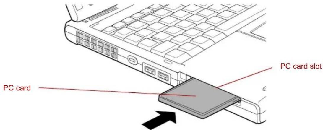
text_image
PC card slot PC cardInserting the PC card
- After inserting the PC card, refer to the PC card's documentation and check the configuration in Windows to make sure it is appropriate for your PC card.
Removing a PC card
To remove the PC card, follow the steps below.
- Open the Safely Remove Hardware icon on the Task Bar.
- Point to PC card and click.
- Press the PC card eject button to extend it.

If the PC card is not inserted all the way, the eject button may not cause it to pop out sufficiently to allows it to be grasped. Be sure to push the PC card firmly into the computer and slide the eject button again.
- Press the extended eject button to pop the card out slightly.
- Grasp the PC card and draw it out.
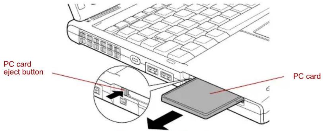
text_image
PC card eject button PC cardRemoving the PC card
Bridge media slot
This slot lets you insert SD memory card, SDIO card, Memory Stick (Pro) and xD picture card.

This Bridge media slot supports the following cards.
■SD card (SD memory card, SDIO card)
Memory Stick
■Memory Stick PRO
xD picture card
Precautions on using cards.
Please note that not all cards have been tested and verified to work correctly. Therefore, it is not possible to guarantee that all cards will operate properly.
Media care
Observe the following precautions when handling the card.
Card care
■Do not twist or bend cards.
■Do not expose cards to liquids or store in humid areas or lay media close to containers of liquid.
- Do not touch the metal part of a card or expose it to liquids or let it get dirty.
■After using card, return it to its case.
■The card is designed so that it can be inserted only one way. Do not try to force the card into the slot.
Do not leave an card partially inserted in the slot. Press the card until you hear it click into place.
Memory card care
- Set the write-protect switch to the lock position, if you do not want to record data.
■ Memory cards are consumable items, so make sure you back up important data.
■Do not write to an SD card if the battery power is low. Low power could affect writing accuracy.
■Do not remove an SD card while read/write is in progress.

For more details on using memory cards, see manuals accompanying the cards.
SD card
Set the SD-card type SD memory cards and Bluetooth ^™ SDIO cards in the Bridge Media slot.

Keep foreign objects out of the Bridge media slot. Never allow metal objects, such as screws, staples and paper clips, to enter the PC or keyboard. Foreign metal objects can create a short circuit, which can cause PC damage and fire, possibly resulting in serious injury.
Inserting an SD card
To insert an SD card, follow the steps below.
-
Insert an SD card in the Bridge media slot.
-
Press gently to ensure a firm connection.
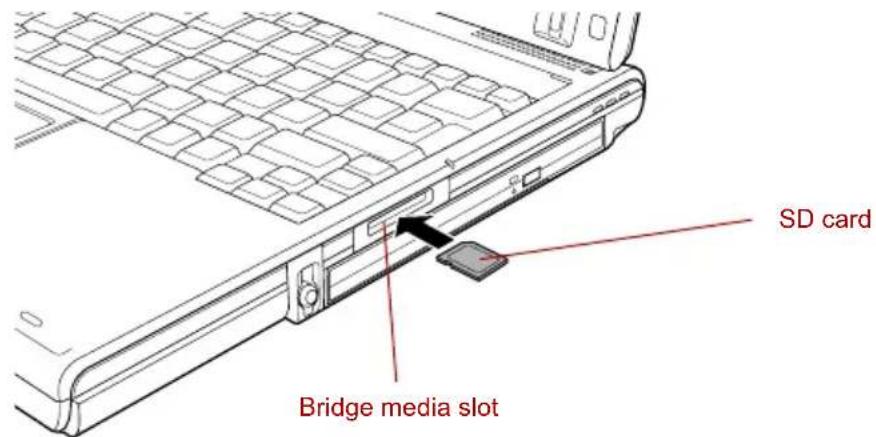
text_image
SD card Bridge media slotInserting an SD card

■Make sure the SD card is oriented properly before you insert it.
■Do not turn the computer off or switch to Standby Mode or Hibernate Mode while files are being copied - doing so may cause data to be lost.
Removing an SD card
To remove an SD card, follow the steps below.
- Open the Safely Remove Hardware icon on the Task Bar.
- Point to SD card and click.
- Push in the card and release it to pop the card out slightly.
- Grasp the card and remove it.
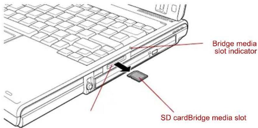
text_image
Bridge media slot indicator SD cardBridge media slotRemoving an SD card

Make sure the Bridge media slot indicator is out before you remove the SD card or turn off the computer's power. If you remove the SD card or turn off the power while the computer is accessing the SD card you may lose data or damage the card.
■Do not remove an SD card while the computer is in Standby or Hibernation mode. The computer could become unstable or data in the SD card could be lost.
SD memory card
SD cards let you easily transfer data from devices, such as digital cameras and Personal Digital Assistants, that use SD card flash-memory. The cards have a high level of security and copy protection features.

SD memory cards comply with SDMI (Secure Digital Music Initiative), which is a technology adopted to prevent unlawful copy or playback of digital music. For this reason, you cannot copy or playback protected material on another computer or other device. You may not use the reproduction of any copyrighted material except for your personal enjoyment.
Formatting an SD card
SD memory cards are sold already formatted in conformity to specific standards. If you format the SD card again, be sure to format it with the TOSHIBA SD memory card format utility, not with the format commands provided within Windows.
In order to run TOSHIBA SD memory card format, click start, point to All Programs, point to TOSHIBA, point to Utilities and click SD memory card Format.
The TOSHIBA SD memory card format utility does not format the protected area of the SD memory card. Should you need to format all areas of the memory card, including the protected area, you will need to obtain an appropriate application that applies the copy protection system.
SDIO card
Add the Bluetooth ^™ wireless communication function to a computer with the SDIO card.
Memory Stick/Memory Stick Pro
The computer is equipped with a Bridge media slot that can accommodate Memory Stick/Memory Stick Pro flash memory cards with various memory capacities. Memory Stick let you easily transfer data from devices, such as digital cameras and Personal Digital Assistants, that use Memory Stick technology.

Keep foreign objects out of the Bridge media slot. Never allow metal objects, such as screws, staples and paper clips, to enter the PC or keyboard. Foreign metal objects can create a short circuit, which can cause PC damage and fire, possibly resulting in serious injury.

■The slot does not support Magic Gate functions.
■Memory Stick Duo/PRO Duo and the Memory Stick adaptor are not compatible with the Bridge media slot. Do not insert Memory Stick Duo/PRO Duo into the slot. Data may be lost or damaged if you use any card other than those supported.
Write protection
Memory Stick can be write protected to safeguard your data. To write-protect a Memory Stick, slide the lock on the back of the Memory Stick to the lock position.
Inserting a Memory Stick
To insert a Memory Stick, follow the steps below.
-
Insert the Memory Stick into the Bridge media slot.
-
Press gently to ensure a firm connection.
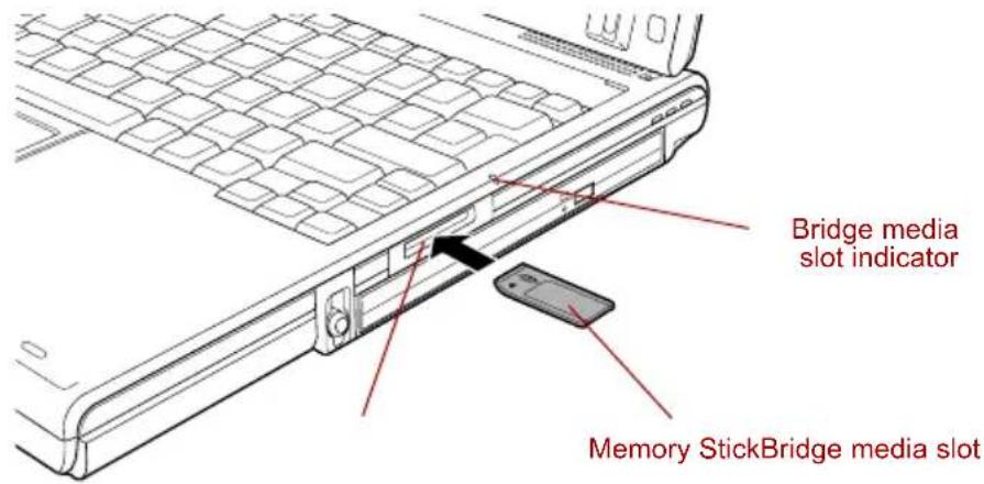
text_image
Bridge media slot indicator Memory StickBridge media slotInserting a Memory Stick
Removing a Memory Stick
To remove a Memory Stick, follow the steps below.
-
Open the Safely Remove Hardware icon on the Task Bar.
-
Point to Memory Stick and click.
-
Push in the card and release it to pop the card out slightly.
-
Grasp the card and remove it.

■ Make sure the Bridge media slot indicator is out before you remove the Memory Stick or turn off the computer's power. If you remove the Memory Stick or turn off the power while the computer is accessing the Memory Stick you may lose data or damage the card.
■Do not remove a Memory Stick while the computer is in Standby or Hibernation mode. The computer could become unstable or data in the Memory Stick could be lost.
xD picture card
The computer is equipped with a Bridge media slot that can accommodate xD picture cards with various memory capacities. The xD picture card let you easily transfer data from devices, such as digital cameras that use xD picture card flash-memory.

Keep foreign objects out of the Bridge media slot. Never allow metal objects, such as screws, staples and paper clips, to enter the PC or keyboard. Foreign metal objects can create a short circuit, which can cause PC damage and fire, possibly resulting in serious injury.
Inserting an xD picture card
To insert an xD picture card, follow the steps below.
- Insert the xD picture card into the Bridge media slot.
- Press gently to ensure a firm connection.
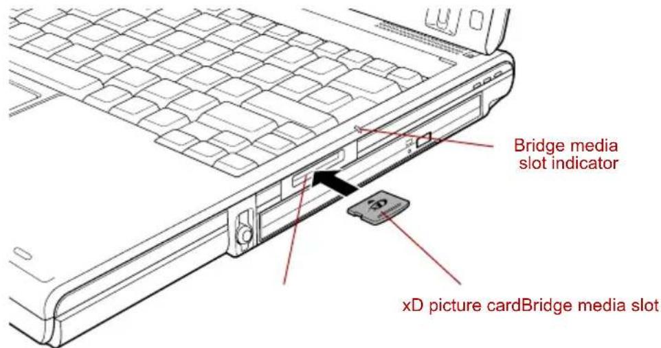
text_image
Bridge media slot indicator xD picture cardBridge media slotInserting an xD picture card
Removing an xD picture card
To remove an xD picture card, follow the steps below.
- Open the Safely Remove Hardware icon on the Task Bar.
- Point to xD picture card and click.
- Push in the card and release it to pop the card out slightly.
- Grasp the card and remove it.

■ Make sure the Bridge media slot indicator is out before you remove the xD picture card or turn off the computer's power. If you remove the xD picture card or turn off the power while the computer is accessing the xD picture card you may lose data or damage the card.
Do not remove an xD picture card while the computer is in Standby or Hibernation mode. The computer could become unstable or data in the xD picture card could be lost.
Memory expansion
You can install additional memory in the computer's memory module slot to increase the amount of RAM. This section describes how to install and remove a memory module.

Place a mat beneath the computer to prevent scratching or damaging the computer's lid when installing/replacing the memory module. Avoid mats made of materials that generate static electricity.
■When you install or remove a memory module, ensure that you do not touch any other internal areas of the computer.

■Use only memory modules approved by TOSHIBA.
■Do not try to install or remove a memory module under the following conditions as you can damage the computer and/or the module, and you risk losing data:
a. The computer is turned on.
b. The computer was shut down using either Standby Mode or Hibernation mode.
c. Wake-up on LAN is enabled.
d. Wake-up on Wireless LAN is enabled.
- Be careful not to let screws or other foreign matter fall into the computer. It could cause malfunction or electric shock.
■Expansion memory is a precision electronic component that may be fatally damaged by static electricity. Since the human body can carry static electricity, it is important that you discharge yourself before touching or installing any expansion memory modules. To discharge your body's static electricity, simply touch any metal close to you with bare hands.
If you install a memory module that is not compatible with the computer, a beep will sound when you turn on the power. If the incompatible module is installed in slot A, there will be a long beep (1 second) followed by one short beep (0.5 seconds), while if the incompatible module is in slot B, there will be a long beep followed by two short beeps. In the event both modules are incompatible, there will be a long beep followed by one short beep, a pause, and then a long beep followed by two short beeps. In all instances you should shut down the computer and remove the incompatible module(s).

Use a point size 1 Phillips screwdriver to remove and fasten the screws. Use of an incorrect screwdriver can damage the screw heads.
Installing a memory module
There are slots for two memory modules. The procedures are the same for installing either module.
- Set the computer to boot mode and turn the computer's power off. Make sure the Power indicator is off. Refer to the Turning on the power section in Chapter 3, Getting Started.
- Remove AC adaptor and all cables connected to the computer.
- Turn the computer upside down and remove the battery pack. Refer to Replacing the battery pack section in Chapter 6, Power and Power-Up Modes, for details.
- Turn your computer over.
- Push the display latch on the front of the computer and open the LCD display panel.
- Slip your finger under a notch at the end of the keyboard brace and lift up to release latches and remove the keyboard brace.
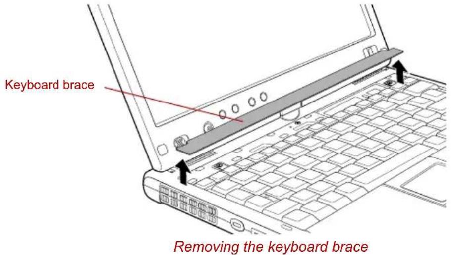
text_image
Keyboard brace Removing the keyboard brace- Remove two screws securing the keyboard.

Use a point size 1 Phillips screwdriver.
- Lift up the back of the keyboard, rotate it toward you and lay in face down on the palm rest.

When you move the keyboard forward, do not touch the keys. Doing so could cause misalignment. Hold the keyboard by the sides and lay it gently on the palm rest.
The keyboard is connected to the computer by a keyboard ribbon cable. Be careful not to apply tension to this cable when you lift up the keyboard. Do not try to disconnect this cable.
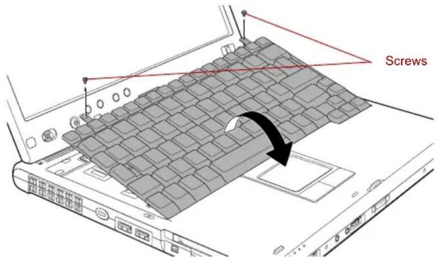
text_image
ScrewsRemoving two screws and rotate the keyboard
- Remove the two screws and take off the memory module cover.
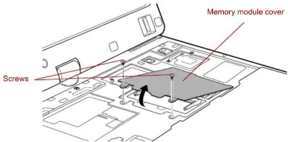
text_image
Screws Memory module coverRemoving the memory module cover

■Do not touch the connectors on the memory module or on the computer. Debris on the connectors may cause memory access problems.
The memory module cover will be hot after using the computer for long periods of time. Exercise caution when removing.

The slot A is reserved for main memory. Use the slot B for expanded memory. If only one card is installed, use the slot A.
- Fit the memory module's connectors into the socket at about a 45 degree angle and push the module down until latches on either side snap into place.
Align the notch of the memory module with that of the memory slot and gently insert the module into the slot.
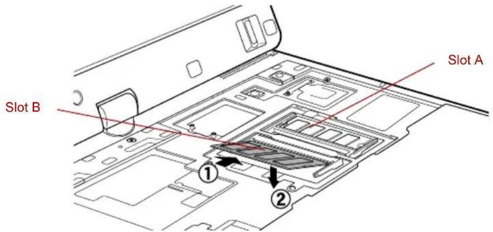
text_image
Slot B Slot A ① ②Installing the memory module
- Screw in the two screws and replace the memory module cover.
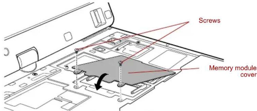
text_image
Screws Memory module coverSeating the memory module cover
- Tuck the keyboard ribbon cable into the groove under the palm rest.
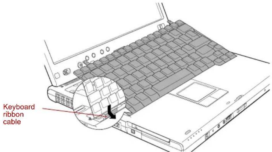
text_image
Keyboard ribbon cableTuck the keyboard ribbon cable

Do not bend the keyboard ribbon cable.
- Insert the tabs on the front of the keyboard into the corresponding notches on the computer and place the keyboard down.

When seating the keyboard, be sure to connect the circuit board if the keyboard ribbon cable was pulled out while you were removing the keyboard.
- Screw the two screws and secure the keyboard.

Be sure to use all two screws removed in step 7. Make sure no screw was dropped into the computer. Make sure no foreign matter can be found.
-
Set the keyboard brace into its groove and press down to secure the latches.
-
Install the battery pack. Refer to Replacing the battery pack section in Chapter 6, Power and Power-Up Modes, for details.
-
Turn your computer over.
-
Turn the power on and make sure the added memory is recognized. Click start, click Control Panel, click Performance and Maintenance and select the System icon. Open System Properties window and click General tab.
Removing a memory module
To remove the memory module, make sure the computer is in boot mode then:
-
Set the computer to boot mode and turn the computer's power off. Make sure the Power indicator is off.
-
Remove AC adaptor and all cables connected to the computer.
-
Turn the computer upside down and remove the battery pack. Refer to Replacing the battery pack section in Chapter 6, Power and Power-Up Modes, for details.
-
Follow steps 4 through 9 in Installing memory module to remove the memory module cover.
-
Push the latches to the outside to release the memory module. A spring will force one end of the memory module up.
-
Grasp the sides of the module and pull it out.

If you use the computer for a long time, the memory modules and the circuits locating close to the memory modules will become hot. In this case, let them cool to room temperature before you replace them. Or you will get burnt if you touch any of them.
■Do not touch the connectors on the memory module or on the computer. Debris on the connectors may cause memory access problems.
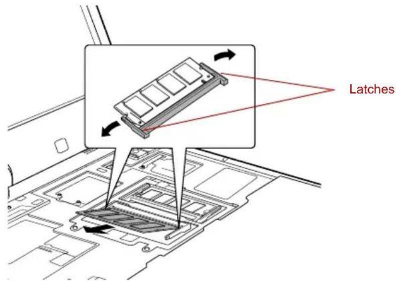
text_image
LatchesRemoving the memory module
-
Rotate the keyboard back into place and secure the keyboard brace as described in the previous section.
-
Install the battery pack. Refer to Replacing the battery pack section in Chapter 6, Power and Power-Up Modes, for details.
-
Turn your computer over.
Battery Pack
You can increase the portability of the computer with additional battery packs. If you're away from an AC power source and your battery runs low, you can replace it with a freshly charged battery. Refer to Chapter 6, Power and Power-Up Modes.
Universal AC Adaptor
If you frequently transport the computer between different sites such as your home and office, purchasing an AC adaptor for each location will reduce the weight and bulk of your carrying load.
Slice Expansion Battery
This battery pack increases your computer's operating time when a main battery pack is also installed. For details on using the battery pack, follow the steps below.
Connecting the Slice Expansion Battery
Follow the steps below to connect the Slice Expansion Battery to the computer

When handling Slice Expansion Battery, be careful not to short circuit the terminals. Also do not drop, hit or otherwise apply impact; do not scratch or break the casing and do not twist or bend the latches of it.
- Be sure the computer's power is off and all cables are disconnected.
- Lay the computer upside down.
- Remove the protective cap from the Slice Expansion Battery.
- Open latches on the Slice Expansion Battery and fit a tab on the battery into the docking port on the underside of the computer
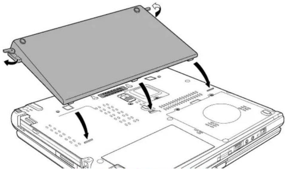
text_image
Diagram showing a device rear panel with labeled ports and internal components, indicating assembly or status.Seating the Slice Expansion Battery
- Close the latches to secure the Slice Expansion Battery to the computer.
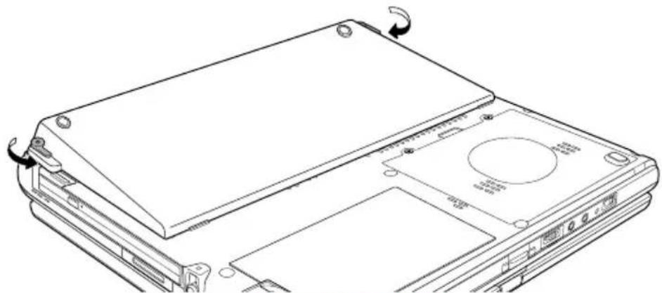
natural_image
Line drawing of a computer chassis with labeled components and directional arrows indicating rotation (no text or symbols present)Securing the latches
Disconnecting the Slice Expansion Battery
Follow the steps below to disconnect the Slice Expansion Battery to the computer.
- Save your work.
- Turn the computer's power off. Make sure the Power indicator is off.
- Remove all cables connected to the computer.
- Lay the computer upside down.
- Push the release latches in the direction of the arrows.
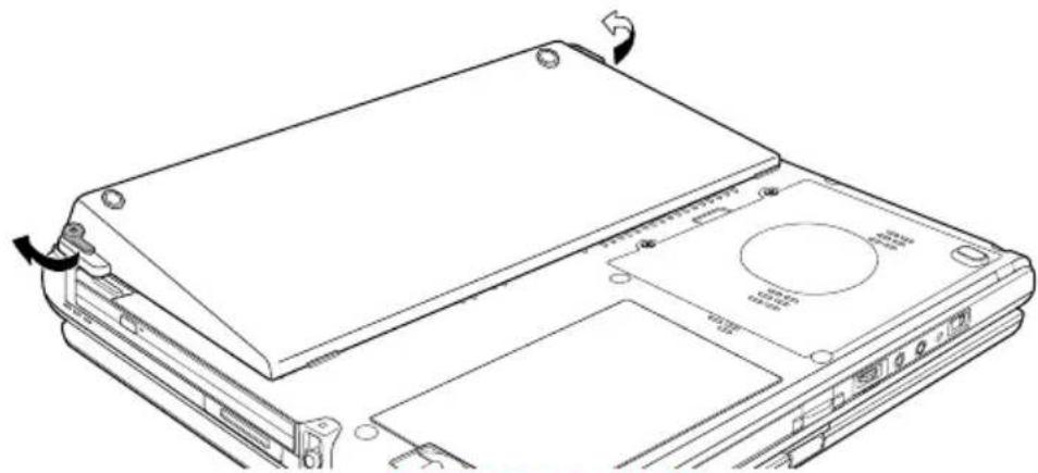
natural_image
Line drawing of a device chassis with labeled ports and connectors (no text or symbols)Releasing the latches
- Lift off the Slice Expansion Battery.
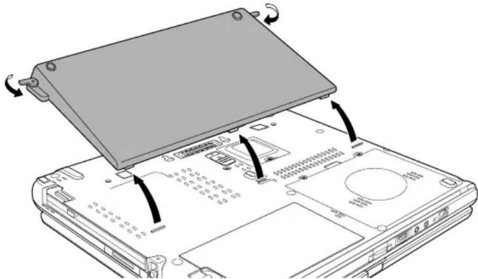
text_image
Diagram showing device rear panel with labeled ports and directional arrows indicating assembly or movementRemoving the Slice Expansion Battery
- Be sure to replace the protective cap before storing the Slice Expansion Battery.
Battery Charger
The battery charger provides a convenient way to charge battery packs without requiring the use of your computer. The battery charger holds up to two battery packs (lithium ion).
HDD Kit (Serial-ATA)
An extra hard disk drive expands the flexibility of your system and lets you carry your data without carrying the computer.

Use a size 1 Phillips screwdriver.
Removing the hard disk drive pack
To remove the hard disk drive pack, follow the steps below.
- Set the computer to boot mode and turn off the power.
- Disconnect the AC adaptor and all external cables connected to the computer.
- Turn the computer upside down and remove the battery pack. Refer to Replacing the battery pack section in Chapter 6, Power and Power-Up Modes, for details.
- Loosen two screws securing the hard disk drive cover.
- A small row of ridges marks the latches securing the cover. Press on these ridges until you hear a click.
- Press on the arrows and lift the cover up and out to remove it.
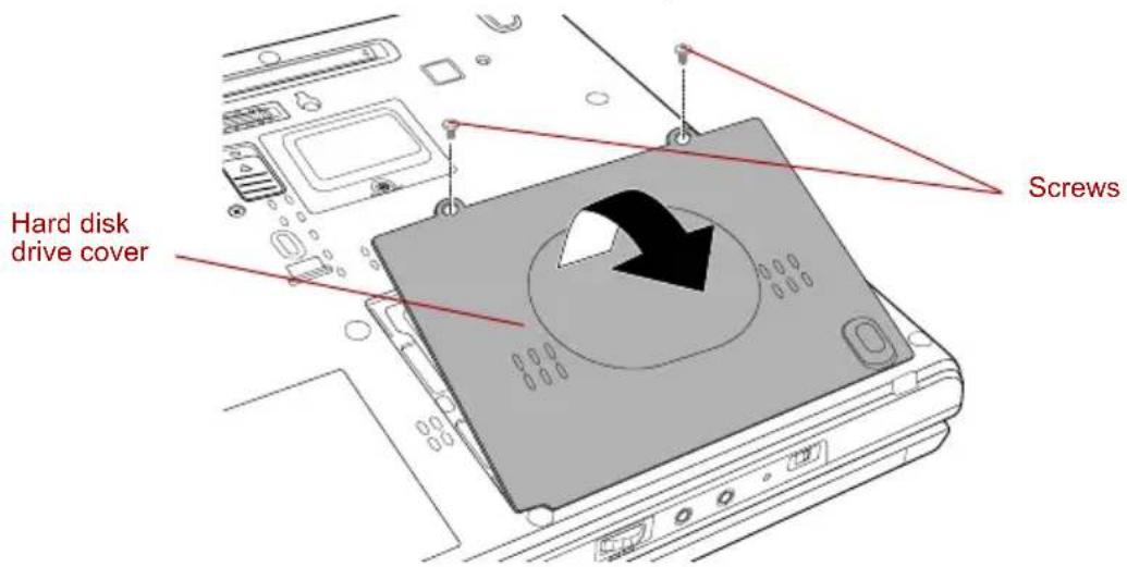
text_image
Hard disk drive cover ScrewsRemoving the hard disk drive cover
-
Reposition the hard disk drive until it is vertical.
-
With the hard disk drive in a vertical position, lift it straight up and away from the connector.
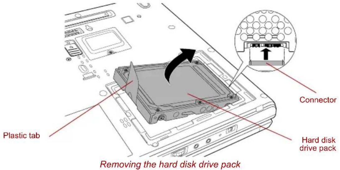
text_image
Plastic tab Removing the hard disk drive pack Connector Hard disk drive packInstalling the HDD Kit (Serial-ATA)
To install the HDD Kit (Serial-ATA), follow the steps below.
- Move the connector until it is vertical.
- Hold the hard disk drive vertically with its label on the left.
- Connect the hard disk drive to the connector.

Ensure that the hard disk drive is connected to the connector in a vertical position. If the hard disk drive is slanted and connected to the connector, it might damage the connector.
- With the connector connected, lower the hard disk drive down to the storage position.
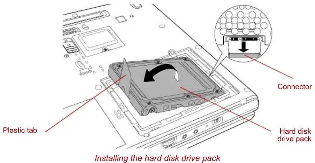
text_image
Plastic tab Installing the hard disk drive pack Connector Hard disk drive pack- Seat the cover and press down until the latches click into place.
- Secure the cover with two screws.
- Turn your computer over.
Ultra Slim Bay HDD Adaptor
You can increase your computer's data storage capacity by installing an additional 80.0 billion bytes (74.53 GB) and 100.0 billion bytes (93.16 GB) hard disk drive in the Ultra Slim Bay.
To install a hard disk drive in the Ultra Slim Bay HDD adaptor follow the steps below.
- Slide the lock to the unlock position and open the lid.
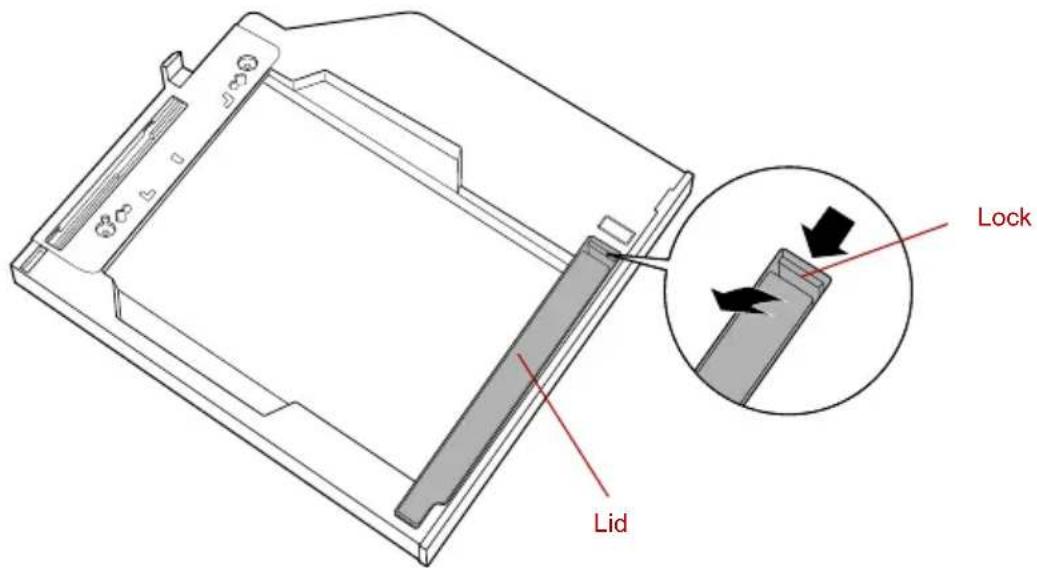
text_image
Lid LockOpening the lid
- Insert the hard disk drive in the Ultra Slim Bay HDD adaptor and push forward to ensure a firm connection. Tuck the Plastic tab underneath the hard disk drive.
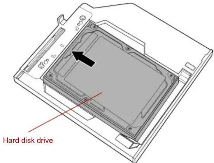
text_image
Hard disk driveInserting the hard disk drive
- Close the lid and slide the lock to the lock position.
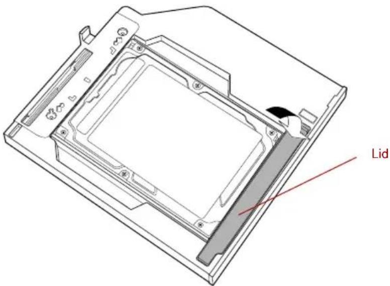
text_image
LidClosing the lid
For details on inserting the Ultra Slim Bay HDD adaptor in the computer's Ultra Slim Bay slot, refer to Chapter 4, Operating Basics.
USB FDD Kit
The USB FDD Kit module can be connected to a USB port. For details on connecting the USB floppy disk drive module, refer to Chapter 4, Operating Basics.
Tablet PC Pen
Use it as a spare to your computer. Spare pen tip and draw-out tool are included. Refer to Chapter 6, Power and Power-Up Modes, for the detailed usage.
Reserve Pen
Supplied pen uses a pen instead of Supplied pen at the time of loss or breakage. Refer to Chapter 6, Power and Power-Up Modes, for the detailed usage.
External monitor
An external analog monitor can be connected to the external monitor port on the computer. The computer supports XGA and SXGA+ video modes. To connect a monitor, follow the steps below.
- Turn the computer's power off.
- Connect the monitor cable to the external monitor port and tighten the screws on the left and right hand side.
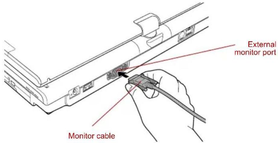
text_image
External monitor port Monitor cableConnecting the monitor cable to the external monitor port
- Turn the monitor's power on.
- Turn the computer's power on.
When you turn on the power, the computer automatically recognizes the monitor and determines whether it is color or monochrome.
However, the Windows Desktop appears on a display device that you used last time to shut down your computer, if the display device exists when you turn on the power.
To change the display settings, press Fn + F5. If you disconnect the external monitor before you turn the computer's power off, be sure to press Fn + F5 to switch to the internal display. Refer to Chapter 5, The Keyboard, for details on using hot keys to change the display setting.
i.LINK (IEEE1394)
i.LINK (IEEE1394) is used for high-speed data transfer for a range of compatible devices such as:
Digital video cameras
■Hard disk drives
MO drives
■Optical media drives

i.LINK uses a four-pin connector, which does not carry any electric current. External devices will need their own power supply to operate.
Precautions
■Make a back-up of your data before transferring it to the computer. There is a possibility that the original data will be damaged. There is a particular risk that some frames will be deleted in the case of digital video transfer. TOSHIBA assumes no liability for such loss of data.
■Do not transfer data in areas where static electricity is easily generated or in areas subjected to electronic noise. Data can be destroyed.
If you are transferring data through an IEEE1394 hub, do not connect or disconnect other devices from the hub during data transfer. There is a likelihood that data will be damaged. Connect all devices to the hub before you turn on the computer's power.
■You may not use any copyrighted video or music data copied from a video camera except for your personal enjoyment.
If you connect/disconnect an i.LINK device to/from another i.LINK device that is currently exchanging data with the computer, data frames might be dropped.
■ Make sure data transfer has ended or turn off the computer, before you:
■Connect/disconnect an i.LINK device to/from the computer.
■ Connect/disconnect an i.LINK device to/from another i.LINK device that is connected to the computer.
Connecting
- Make sure the connectors are properly aligned and plug the i.LINK (IEEE1394) cable into the computer.
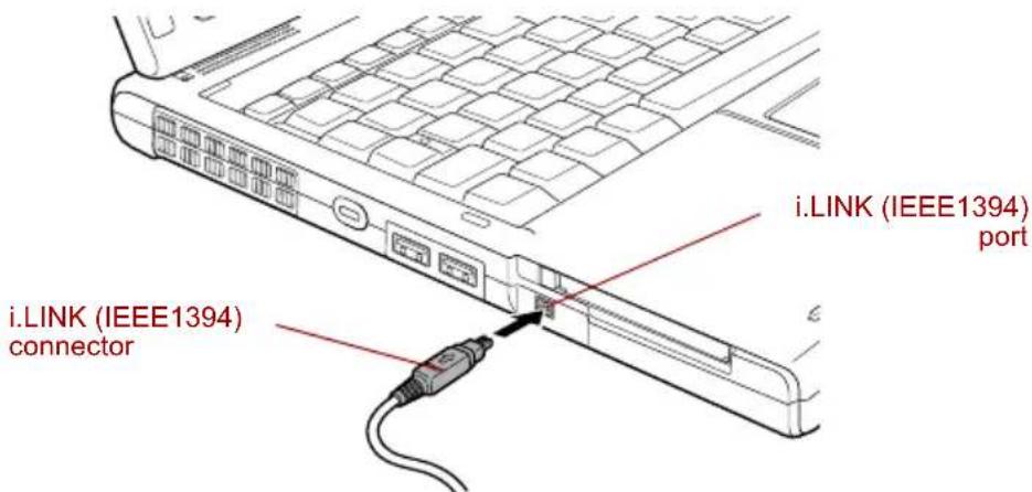
text_image
i.LINK (IEEE1394) port i.LINK (IEEE1394) connectorConnecting the i.LINK (IEEE1394) cable into the computer
- Plug the other end of the cable into the device.
Note the following when you use i.LINK:
■You may need to install drivers for your i.LINK devices.
Not all i.LINK devices have been tested. Therefore, compatibility with all i.LINK devices cannot be guaranteed.
■Some devices might not support standby or automatic off functions.
■Do not connect or disconnect an i.LINK device while it is using an application or when the computer is automatically shutting it down to save power. Data might be destroyed.
Disconnecting
- Open the Safely Remove Hardware icon on the Task Bar.
- Point to i.LINK (IEEE1394) device and click.
- Disconnect the cable from the computer then from the i.LINK device.

Refer also to the documentation that came with your i.LINK device.
TOSHIBA Express Port Replicator
In addition to the ports available on the computer, the TOSHIBA Express Port Replicator. The TOSHIBA Express Port Replicator connects directly to the docking interface on the underside of the computer. The AC adaptor connects the TOSHIBA Express Port Replicator to a power source.

The computer must be configured properly before connecting to a LAN. Logging onto a LAN using the computer's default settings could cause a malfunction in LAN operation. Check with your LAN administrator regarding set-up procedures.

■You must connect the AC adaptor before you connect to a TOSHIBA Express Port Replicator.
When a TOSHIBA Express Port Replicator is connected to the computer, you can not use the following computer's ports: LAN jack, DC IN 15V jack, External monitor port.
When connecting an AC Adaptor to the TOSHIBA Express Port Replicator, use only the AC Adaptor included with TOSHIBA Express Port Replicator. Do not use the computer's AC Adaptor.
The following ports and accessories are available on the TOSHIBA Express Port Replicator.
RJ45 LAN jack
■External monitor port
DC IN 15V jack
■Security lock slot
■Universal Serial Bus 2.0 port (four)
DVI port
Security lock
Security locks enable you to anchor your computer and optional TOSHIBA Express Port Replicator to a desk or other heavy object to help prevent unauthorized removal of the computer or TOSHIBA Express Port Replicator.
The computer has a security lock slot on the left side. Attach one end of a cable to a desk and the other end to the security lock slot.
- Turn the computer so the left side faces you.
- Align the holes for the security lock and attach the lock.
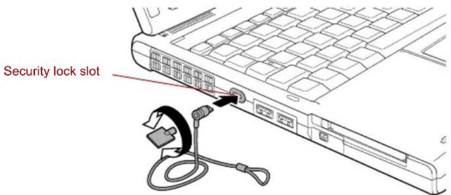
text_image
Security lock slotSecurity lock
Chapter 9
Troubleshooting
TOSHIBA designed the computer for durability. However, should problems occur, following the procedures in this chapter can help to determine the cause.
All readers should become familiar with this chapter. Knowing what might go wrong can help prevent problems from occurring.
Problem solving process
Resolving problems will be much easier if you observe the following guidelines:
■Stop immediately when you recognize a problem exists. Further action may result in data loss or damage. You may destroy valuable problem-related information that can help solve the problem.
■Observe what is happening. Write down what the system is doing and what actions you performed immediately before the problem occurred. If you have a printer attached, print a copy of the screen using PrtSc.
The questions and procedures offered in this chapter are meant as a guide, they are not definitive problem solving techniques. Many problems can be solved simply, but a few may require help from your dealer. If you find you need to consult your dealer or others, be prepared to describe the problem in as much detail as possible.
Preliminary checklist
Consider the simplest solution first. The items in this checklist are easy to fix and yet can cause what appears to be a serious problem.
■Make sure you turn on all peripheral devices before you turn on the computer. This includes your printer and any other external device you are using.
■Before you attach an external device, turn the computer off. When you turn the computer back on it recognizes the new device.
■Make sure all options are set properly in the setup program.
- Check all cables. Are they correctly and firmly attached? Loose cables can cause signal errors.
■Inspect all connecting cables for loose wires and all connectors for loose pins.
- Check that your floppy disk or CD/DVD-ROM is correctly inserted and that the floppy disk's write protect tab is correctly set.
Make notes of your observations and keep them in a permanent error log. This will help you describe your problems to your dealer. If a problem recurs, the log will help you identify the problem faster.
Analyzing the problem
Sometimes the system gives clues that can help you identify why it is malfunctioning. Keep the following questions in mind:
Which part of the system is not operating properly: keyboard, floppy disk drives, hard disk drive, optical media drive, display. Each device produces different symptoms.
Is the operating system configuration set properly? Check the configuration options.
■What appears on the display screen? Does it display any messages or random characters? If you have a printer attached, print a copy of the screen using PrtSc. Look up the messages in the software and operating system documentation. Check that all connecting cables are correctly and firmly attached. Loose cables can cause erroneous or intermittent signals.
■Do any indicators light? Which ones? What color are they? Do they stay on or blink? Write down what you see.
■Do you hear any beeps? How many? Are they long or short? Are they high pitched or low? Is the computer making any unusual noises? Write down what you hear.
Record your observations so you can describe them to your dealer.
| Software The problems may be caused by your software or disk. If you cannot load a software package, the media may be damaged or the program might be corrupted. Try loading another copy of the software.If an error message appears while you are using a software package, check the software documentation. These documents usually include a problem solving section or a summary of error messages.Next, check any error messages in the operating system documentation. |
Hardware If you cannot find a software problem, check your hardware. First run through the items in the preliminary checklist above. If you still cannot correct the problem, try to identify the source. The next section provides checklists for individual components and peripherals.

Before using a peripheral device or application software that is not an authorized Toshiba part or product, make sure the device or software can be used with your PC. Use of incompatible devices may cause injury or may damage your PC.
Hardware and system checklist
This section discusses problems caused by your computer's hardware or attached peripherals. Basic problems may occur in the following areas:
System start-up
Self test
Power
Password
Keyboard
■Internal LCD display panel
Hard disk drive
DVD-ROM&CD-R/RW drive
DVD Super Multi drive
USB floppy disk drive
PC card
SD card
■Memory Stick/Memory Stick Pro
xD picture card
Pointing Device
Fingerprint Sensor
USB device
■Memory expansion
Sound system
External monitor
■i.LINK (IEEE1394) device
Modem
LAN
Wireless LAN
Bluetooth
System start-up
When the computer does not start properly, check the following items:
Self Test
Power Sources
Power-on Password
Self test
When the computer starts up, the self test will be run automatically, and the following will be displayed:
In Touch with Tomorrow TOSHIBA
This message remains on the screen for a few seconds.
If the self test is successful, the computer tries to load the operating system, depending on how the Boot Priority is set in the TOSHIBA HW Setup program.
If any of the following conditions are present, the self test failed:
■The computer stops and does not proceed to display information or messages except the TOSHIBA logo.
■Random characters appear on the screen, and the system does not function normally.
■The screen displays an error message.
Turn off the computer and check all cable connections. If the test fails again, contact your dealer.
Power
When the computer is not plugged into an AC outlet, the battery pack is the primary power source. However, your computer has a number of other power resources, including an intelligent power supply and a Real Time Clock battery. These resources are interrelated and any one could affect apparent power problems. This section provides checklists for AC power and the battery. If you cannot resolve a problem after following them, the cause could lie with another power resource. In such case, contact your dealer.
Overheating power down
If the computer's internal temperature becomes too high, the computer will automatically enter Hibernation or Standby Mode and shut down.
Problem Procedure
| Computer shuts down and DC IN indicator blinks orange | Leave the computer off until the DC IN indicator stops blinking. |

It is recommended to leave the computer off until the interior reaches room temperature even though the DC IN indicator stops blinking.
| If the computer has reached room temperature and still does not start, or if it starts but shuts down quickly contact your dealer. | |
| Computer shuts down and its DC IN indicator is flashing green | Indicates a problem with the heat dispersal system. Please contact your dealer. |
AC power
If you have trouble turning on the computer with the AC adaptor connected, check the DC IN indicator. Refer to Chapter 6, Power and Power-Up Modes for more information.
Problem Procedure
| AC adaptor doesn’t power the computer (DC IN indicator does not glow green) | Check the connections. Make sure the cord is firmly connected to the computer and a power outlet. |
| Check the condition of the cord and terminals. If the cord is frayed or damaged, replace it. If the terminals are soiled, wipe them with cotton or a clean cloth. | |
| If the AC adaptor still does not power the computer, contact your dealer. |
Battery
If you suspect a problem with the battery, check the DC IN indicator as well as the Battery indicator. For information on indicators and battery operation see Chapter 6, Power and Power-Up Modes.
| Problem Procedure | |
| Battery doesn’t power the computer | The battery may be discharged. Connect the AC adaptor to charge the battery. |
| Battery doesn’t charge when the AC adaptor is attached (Battery or Ultra Slim Bay indicator does not glow orange.) | If the battery is completely discharged, it will not begin charging immediately. Wait a few minutes.If the battery still does not charge, make sure the outlet of the AC adaptor is supplying power.Test it by plugging in an appliance. |
| Check whether the battery is hot or cold to the touch. If the battery is too hot or too cold, it will not charge properly. Let it reach room temperature. | |
| Unplug the AC adaptor and remove the battery to make sure the terminals are clean. If necessary wipe them with a soft dry cloth dipped in alcohol. Connect the AC adaptor and replace the battery. Make sure it is securely seated. Check the Battery indicator. If it does not glow, let the computer charge the battery for at least 20 minutes. If the Battery indicator glows after 20 minutes, let the battery continue to charge at least another 20 minutes before turning on the computer.If the indicator still does not glow, the battery may be at the end of its operating life. Replace it. If you do not think the battery is at the end of its operating life, see your dealer. | |
| Battery doesn’t power the computer as long as expected | If you frequently recharge a partially charged battery, the battery might not charge to its full potential. Fully discharge the battery, then try to charge it again. |
| Check the power consumption settings in TOSHIBA Power Saver utility. Consider using a power saving mode. | |
Real Time Clock
Problem Procedure
The following message is Displayed on the LCD screen:
RTC battery is low or CMOS checksum is inconsistent. Press [F1] key to set Date/Time.
The charge in the RTC battery has run out - you will need to set the date and time in the BIOS setup using the following steps:
- Press F1 key. BIOS setup will boot up.
- Set the date in System Date.
- Set the time in System Time.
- Press End key. Confirmation message will appear.
- Press Y key. BIOS setup will terminate and the computer will be rebooted.
Password
Problem Procedure
Cannot enter password
Refer to the TOSHIBA Password Utility section in Chapter 6, Power and Power-Up Modes.
Keyboard
Keyboard problems can be caused by your setup configuration. For more information refer to Chapter 5, The Keyboard.
Problem Procedure
Some letter keys produce numbers
Check that the numeric keypad overlay is not selected. Press Fn + F10 and try typing again.
Output to screen is garbled
Make sure the software you are using is not remapping the keyboard. Remapping involves reassigning the meaning of each key. See your software's documentation.
If you are still unable to use the keyboard, consult your dealer.
Internal LCD display panel
Apparent LCD problems may be related to the computer's setup. Refer to Chapter 7, HW Setup, for more information.
| Problem Procedure | |
| No display | Press hotkeys Fn + F5 to change the display priority, to make sure it is not set for an external monitor. |
| Markings appear on the LCD screen. | The marks may have come from contact with the keyboard or Touch Pad. Try wiping the LCD screen gently with a clean dry cloth. If markings remain, use a good quality LCD screen cleaner, taking care to ensure you let the LCD screen dry before closing it. |
| Problems above remain unresolved or other problems occur | Refer to your software's documentation to determine if the software is causing the difficulty. Run the diagnostic test.Contact your dealer if the problems continue. |
Hard disk drive
| Problem Procedure | |
| Computer does not boot from hard disk drive | Check if a floppy disk is in the floppy disk drive or a CD-ROM is in the optical media drive. Remove any floppy disk and/or CD-ROM and check the Boot priority. Refer to theBoot Prioritysection in Chapter 7, HW Setup. |
| There may be a problem with your operating system files. Refer to your operating system documentation. | |
| Slow performance Your files may be fragmented. Run Disk Defragmenter to check the condition of your files and disk. Refer to your operating system's documentation or online HELP for information on running the Disk Defragmenter. | |
DVD-ROM&CD-R/RW drive
For more information, refer to Chapter 4, Operating Basics.
| Problem Procedure | |
| You cannot access a CD/DVD in the drive | Make sure the drive's disc tray is securely closed. Press gently until it clicks into place. |
| Check whether the drive power is on. If the power is off, click on the Optical Drive Power icon in the task tray and turn on the power. | |
| Open the disc tray and make sure the CD/DVD is properly seated. It should lie flat with the label facing up. | |
| A foreign object in the disc tray could block laser light from reading the CD/DVD. Make sure there is no obstruction. Remove any foreign object. | |
| Check whether the CD/DVD is dirty. If it is, wipe it with a clean cloth dipped in water or a neutral cleaner. Refer to the Media care section in Chapter 4 for details on cleaning. | |
| Some CD/DVDs run correctly, but others do not | The software or hardware configuration may be causing a problem. Make sure the hardware configuration matches your software's needs. Check the CD/DVD's documentation. |
| Check the type of CD/DVD you are using. The drive supports: DVD-ROM: DVD-ROM, DVD-Video CD-ROM: CD-DA, CD-Text, Photo CD^TM (single/multi-session), CD-ROM Mode 1, Mode 2, CD-ROM XA Mode 2 (Form1, Form2), Enhanced CD (CD-EXTRA), Addressing Method 2 | |
| Recordable CD: CD-R, CD-RW | |
| Check the region code on the DVD. It must match that on the DVD-ROM&CD-R/RW drive. Region codes are listed in the Optical media drives section in Chapter 2, The Grand Tour. | |
Problem Procedure
| Cannot write correctly | If you have trouble writing, make sure you are observing the following precautions: |
| ■Use only media recommended by TOSHIBA. | |
| ■Do not use the mouse or keyboard during writing. | |
| ■Use only the software supplied with the computer for recording. | |
| ■Do not run or start other software during writing. | |
| ■Do not jar the computer during writing. | |
| ■Do not connect/disconnect external devices or install/remove internal cards during writing. | |
| If problems persist, contact your dealer. |
DVD Super Multi drive
For more information, refer to Chapter 4, Operating Basics.
| Problem Procedure | |
| You cannot access a CD/DVD in the drive | Make sure the drive's disc tray is securely closed. Press gently until it clicks into place. |
| Check whether the drive power is on. If the power is off, click on the Optical Drive Power icon in the task tray and turn on the power. | |
| Open the disc tray and make sure the CD/DVD is properly seated. It should lie flat with the label facing up. | |
| A foreign object in the disc tray could block laser light from reading the CD/DVD. Make sure there is no obstruction. Remove any foreign object. | |
| Check whether the CD/DVD is dirty. If it is, wipe it with a clean cloth dipped in water or a neutral cleaner. Refer to the Media care section in Chapter 4 for details on cleaning. | |
| Some CD/DVDs run correctly, but others do not | The software or hardware configuration may be causing a problem. Make sure the hardware configuration matches your software's needs. Check the CD/DVD's documentation. |
Check the type of CD/DVD you are using. The drive supports:
DVD-ROM: DVD-ROM, DVD-Video
CD-ROM: CD-DA, CD-Text, Photo CD™
(single/multi-session),
CD-ROM Mode 1, Mode 2,
CD-ROM XA Mode 2
(Form1, Form2),
Enhanced CD (CD-EXTRA),
Addressing Method 2
Check the region code on the DVD. It must match that on the DVD Super Multi drive. Region codes are listed in the Optical media drives section in Chapter 2, The Grand Tour.
USB floppy disk drive (optional)
For more information, refer to Chapter 4, Operating Basics.
Problem Procedure
| Drive does not operate There may be a faulty cable connection. Check the connection to the computer and to the drive. |
| Some programs run correctly but others do not | The software or hardware configuration may be causing a problem. Make sure the hardware configuration matches your software needs. |
| You cannot access the external 3 1/2" floppy disk drive | Try another floppy disk. If you can access the floppy disk, the original floppy disk (not the drive) is probably causing the problem. |
If problems persist, contact your dealer.
PC card
Refer also to Chapter 8, Optional Devices.
Problem Procedure
| PC card error occurs | Reseat the PC card to make sure it is firmly connected. |
Make sure the connection between the external device and the card is firm.
Check the card's documentation.
If problems persist, contact your dealer.
SD card
Refer also to Chapter 8, Optional Devices.
Problem Procedure
| SD card error occurs | Reseat the SD card to make sure it is firmly connected. |
| Check the card's documentation. |
| You cannot write to an SD memory card | Make sure the card is not write protected. |
| You cannot read a file Make sure the target file is on the SD memory card inserted in the slot.If problems persist, contact your dealer. |
Memory Stick/Memory Stick Pro
Refer also to Chapter 8, Optional Devices.
Problem Procedure
| Memory Stick/Memory Stick Pro error occurs | Reseat the Memory Stick/Memory Stick Pro to make sure it is firmly connected.Check the card’s documentation. |
| You cannot write to an Memory Stick/Memory Stick Pro | Make sure the Memory Stick/Memory Stick Pro is not write protected. |
| You cannot read a file Make sure the target file is on the Memory Stick/Memory Stick Pro inserted in the slot. If problems persist, contact your dealer. |
xD picture card
Refer also to Chapter 8, Optional Devices.
Problem Procedure
| xD picture card error occurs | Reseat the xD picture card to make sure it is firmly connected. Check the card's documentation. |
| You cannot read a file Make sure the target file is on the xD picture card inserted in the slot.If problems persist, contact your dealer. |
Pointing device
If you are using a USB mouse, also refer to the USB section in this chapter and to your mouse documentation.
Touch Pad
| Problem Procedure | |
| On-screen pointer does not respond to Pad operation | The system might be busy. If the pointer is shaped as an hourglass, wait for it to return to its normal shape and try again to move it. |
| Double-tapping does not work | Try changing the double-click speed setting in the mouse control utility.1. Click start, click Control Panel, click Printers and Other Hardware and select Mouse icon.2. Click the Buttons tab.3. Set the double-click speed as required and click OK. |
| The mouse pointer moves too fast or too slow | Try changing the speed setting in the mouse control utility.1. Click start, click Control Panel, click Printers and Other Hardware and select Mouse icon.2. Click the Pointer Options tab.3. Set the speed as required and click OK. If problems persist, contact your dealer. |
| The reaction of Touch pad is either too sensitive or not sensitive enough. | Adjust the touch Sensitivity.1. Click start and open the Control Panel.2. Click the Printers and Other Hardware icon.3. Click the Mouse icon.4. Click the Advanced tab.5. Click the Advanced feature settings button.6. Click Touch Pad tab. Click the Settings button in the Pointer speed and tapping settings.7. Detailed Touch Pad setting is displayed.8. Move the slide of adjust the pointer speed in relation to the standard Windows setting. Click the OK button.9. Click the OK button on Advanced feature setting screen. |
USB mouse
| Problem Procedure | |
| On-screen pointer does not respond to mouse operation | The system might be busy. If the pointer is shaped as an hourglass, wait for it to resume its normal shape and try again to move it.Make sure the mouse is properly connected to the USB port. |
| Double-clicking does not work | Try changing the double-click speed setting in the mouse control utility.Click start, click Control Panel, click Printers and Other Hardware and select Mouse icon.Click the Buttons tab.Set the double-click speed as required and click OK. |
| The mouse pointer moves too fast or too slow | Try changing the speed setting in the mouse control utility.Click start, click Control Panel, click Printers and Other Hardware and select Mouse icon.Click the Pointer Options tab.Set the speed as required and click OK. |
| The mouse pointer moves erratically | The mouse might be dirty. Refer to your mouse documentation for instructions on cleaning.If problems persist, contact your dealer. |
Fingerprint Sensor
| Problem Procedure | |
| Reading of the fingerprint was not successful. | Please try again using the correct posture. Align your fingertip with the sensor as shown in the drawing and Swipe. Refer to Using the Fingerprint Sensor in Chapter 4, Operating Basics.Try the recognition process again using another enrolled finger. |
| The fingerprint cannot be read due to injuries to the finger. | Try the recognition process again using another enrolled finger.If fingerprints from all the enrolled fingers cannot be read, please logon by using the keyboard to input the password for the time being.If problems persist, contact your dealer. |
USB device
Refer also to your USB device's documentation.
Problem Procedure
| USB device does not work | Check for a firm cable connection between the USB ports on the computer and the USB device. |
| Make sure the USB device drivers are properly installed. Refer to your Windows XP documentation for information on checking the drivers. | |
| If you are using an operating system that does not support USB, you can still use a USB mouse and/or USB keyboard. If these devices do not work, make sure the USB KB/Mouse Legacy Emulation item in HW Setup is set to Enabled. If problems persist, contact your dealer. |
Memory expansion
Refer also to Chapter 8, Optional Devices, for information on installing memory modules.
Problem Procedure
| Beep sounds.(Two beeps, a dash and a dot, for a defective memory module in slot A.Three beeps, a dash and two dots for slot B.When both beeps sound, both memories in slot A and B are defective.) | Make sure the memory module installed in the memory slot is compatible with the computer.If an incompatible module has been installed, follow the steps below.1. Turn off the computer.2. Disconnect the AC adaptor and all peripheral devices.3. Remove the battery pack.4. Remove the memory module.5. Install the battery and/or connect the AC adaptor.6. Turn on the power.If problems persist, contact your dealer. |
Sound system
Refer also to documentation for your audio devices.
Problem Procedure
No sound is heard Adjust the volume control dial.
| Check the software volume settings. | |
| Make sure the headphone connection is secure. If problems persist, contact your dealer. | |
| Check Windows Device Manager. Make sure the sound function is enabled and that settings for I/O address, Interrupt level and DMA are correct for your software and do not conflict with other hardware devices that you may have connected to the computer. | |
| Annoying sound is heard | You may be experiencing feedback. Refer to Sound System in Chapter 4, Operating Basics. If problems persist, contact your dealer. |
External monitor
Refer also to Chapter 8, Optional Devices, and to your monitor's documentation.
| Problem Procedure | |
| Monitor does not turn on | Make sure that the external monitor's power switch is on. Confirm that the external monitor's power cable is plugged into a working power outlet. |
| No display Try adjusting the contrast and brightness controls on the external monitor. | |
| Press hot keys Fn + F5 to change the display priority and make sure it is not set for the internal LCD. | |
| Display error occurs Check that the cable connecting the external monitor to the computer is attached firmly. If problems persist, contact your dealer. | |
i.LINK (IEEE1394) device
| Problem Procedure | |
| i.LINK device does not function | Make sure the cable is securely connected to the computer and to the device. |
| Make sure the device's power is turned on. | |
| Reinstall the drivers. Open the Windows Control Panel and double-click the Add Hardware icon. Follow the on-screen directions. | |
| Restart Windows. If problems persist, contact your dealer. | |
Modem
| Problem Procedure | |
| Communication software can’t initialize modem | Make sure the computer’s internal modem settings are correct. Refer to Phone and Modem Properties in the Control Panel. |
| You can hear a dial tone but can’t make a call | If the call is going through a PBX machine, make sure the communication application’s tone dial detection feature is disabled.You can also use the ATX command. |
| You place a call, but a connection can’t be made | Make sure the settings are correct in your communications application. |
| After making a call you can’t hear a ring | Make sure the tone or pulse selection in your communications application is set correctly.You can also use the ATD command. |
| Communication is cut off unexpectedly | The computer will automatically cut off communication when connection with the carrier is not successful for a set time interval. Try lengthening this time interval. |
| A CONNECT display is quickly replaced by NO CARRIER | Check the error control setting in your communications application.You can also use the AT\N command. |
| Character display becomes garbled during a communication session | In data transmission, make sure the parity bit and stop bit settings correspond with those of the remote computer.Check the flow control and communication protocol. |
Problem Procedure
| You cannot receive an incoming call | Check the rings before auto answer setting in your communications application.You can also use the ATS0 command.If problems persist, contact your dealer. |
LAN
Problem Procedure
| Cannot access LAN Check for a firm cable connection between the LAN jack and the LAN hub. | |
| Wake-up on LAN does not work | Make sure the AC adaptor is connected. The Wake-up on LAN function consumes power even when the system is off.If problems persist, consult your LAN administrator. |
Wireless LAN
If the following procedures do not restore LAN access, consult your LAN administrator. For more information on wireless communication, refer to Chapter 4, Operating Basics.
Problem Procedure
| Cannot access Wireless LAN | Make sure the computer’s wireless communication switch is set to on. If problems persist, contact your LAN administrator. |
Bluetooth
For more information on wireless communication, refer to Chapter 4, Operating Basics.
Problem Procedure
| Cannot accessBluetooth device | Make sure the computer’s wireless communication switch is set to on. |
Make sure the Bluetooth Manager is running and the power to the Bluetooth device is turned on.
Make sure no optional Bluetooth PC card and Bluetooth SD card are installed in the computer. The built-in Bluetooth function and an optional Bluetooth PC card cannot operate simultaneously. If problems persist, contact your dealer.
Disposing of PC and PC batteries
■Discard this PC in accordance with ordinances or rules of local regulations. For further information, contact your local government.
This PC contains rechargeable batteries. After repeated use, the batteries will finally lose their ability to hold a charge and you will need to replace them. Under certain applicable laws and regulation, it may be illegal to dispose of old batteries by placing them in the trash.
■Please be kind to our shared environment. Check with your local government authority for details regarding where to recycle old batteries or how to dispose of them properly. This product contains mercury. Disposal of this material may be regulated due to environmental considerations. For disposal, reuse or recycling information, please contact your local government.
If your hard disk or other storage media contains sensitive data, you should be aware that standard deletion procedures do not remove data from the media. These standard deletion procedures include:
■Selecting Delete for a target file
- Putting files in the Recycle Bin and emptying the Recycle Bin
■Reformatting the media
■ Reinstalling an operating system from the recovery CD-ROM
The procedures above delete only the initial part of the data used for file management. This makes the file invisible to the operating system, but the data can still be read by specialized utilities. If you dispose of the PC, please delete all the data on its hard disk drive. Doing so prevents unauthorized use of such data. To ensure your data is not used for unauthorized purposes, you can:
■Physically destroy the hard disk drive
■Use a proven specialized utility to overwrite all data
■Take the hard disk drive to a professional deletion service
All data deletion costs will be borne by you.
TOSHIBA support
If you require any additional help using your computer or if you are having problems operating the computer, you may need to contact TOSHIBA for additional technical assistance.
Before you call
Some problems you experience may be related to software or the operating system, it is important to investigate other sources of assistance first.
Before contacting TOSHIBA, try the following:
■Review troubleshooting sections in the documentation for software and peripheral devices.
If a problem occurs when you are running software applications, consult the software documentation for troubleshooting suggestions. Call the software company's technical support for assistance.
■Consult the dealer you purchased your computer and/or software from. They are your best sources for current information and support.
Where to write
If you are still unable to solve the problem and suspect that it is hardware related, write to TOSHIBA at the location listed in the accompanying warranty booklet or visit www.toshiba-europe.com on the Internet.
Chapter 10
Legal Footnotes
This chapter states the Legal Footnotes information applicable to TOSHIBA computers. In the text in this manual, *XX is used to show which Legal Footnotes description is related to TOSHIBA computers.
Description(s) related to this computer are marked with a blue *XX in this manual. Clicking on *XX will display the related description.
CPU\*1
Central Processing Unit ("CPU") Performance Legal Footnotes.
CPU performance in your computer product may vary from specifications under the following conditions:
■use of certain external peripheral products
■use of battery power instead of AC power
■use of certain multimedia, computer generated graphics or video applications
■use of standard telephone lines or low speed network connections
■use of complex modeling software, such as high end computer aided design applications
■use of several applications or functionalities simultaneously
■use of computer in areas with low air pressure (high altitude >1,000 meters or >3,280 feet above sea level)
■ use of computer at temperatures outside the range of 5°C to 30°C (41°F to 86°F) or >25°C (77°F) at high altitude (all temperature references are approximate and may vary depending on the specific computer model - please refer to your PC documentation or visit the Toshiba website at www.pcsupport.toshiba.com for details).
CPU performance may also vary from specifications due to design configuration.
Under some conditions, your computer product may automatically shutdown. This is a normal protective feature designed to reduce the risk of lost data or damage to the product when used outside recommended conditions. To avoid risk of lost data, always make back-up copies of data by periodically storing it on an external storage medium. For optimum performance, use your computer product only under recommended conditions. Read additional restrictions in your product documentation. Contact Toshiba technical service and support, refer to TOSHIBA support section in Chapter 9 Troubleshooting for more information.
Memory (Main System) ^*2
Part of the main system memory may be used by the graphics system for graphics performance and therefore reduce the amount of main system memory available for other computing activities. The amount of main system memory allocated to support graphics may vary depending on the graphics system, applications utilized, system memory size and other factors. For PC's configured with 4 GB of system memory, the full system memory space for computing activities will be considerably less and will vary by model and system configuration.
Battery Life\*3
Battery life may vary considerably depending on product model, configuration, applications, power management settings and features utilized, as well as the natural performance variations produced by the design of individual components. Published battery life numbers are achieved on select models and configurations tested by Toshiba at the time of publication. Recharge time varies depending on usage. Battery may not charge while computer is consuming full power.
After going through many charge and discharge cycles, the battery will lose its ability to perform at maximum capacity and will need to be replaced. This is a normal phenomenon for all batteries. To purchase a new battery pack, see the accessories information that is shipped with your computer.
HDD Drive Capacity\*4
1 Gigabyte (GB) means 10^9 = 1,000,000,000 bytes using powers of 10. The computer operating system, however, reports storage capacity using powers of 2 for the definition of 1 GB = 2^30 = 1,073,741,824 bytes, and therefore shows less storage capacity. Available storage capacity will also be less if the product includes one or more pre-installed operating systems, such as Microsoft Windows and/or pre-installed software applications, or media content. Actual formatted capacity may vary.
LCD\*5
Over a period of time, and depending on the usage of the computer, the brightness of the LCD screen will deteriorate. This is an intrinsic characteristic of LCD technology.
Maximum brightness is only available when operating in AC power mode. The screen will dim when the computer is operated on battery power and you may not be able to increase the brightness of the screen.
Graphics Processor Unit ("GPU")\*6
Graphics processor unit ("GPU") performance may vary depending on product model, design configuration, applications, power management settings and features utilized. GPU performance is only optimized when operating in AC power mode and may decrease considerably when operating in battery power mode.
Wireless LAN\*7
The transmission speed over the wireless LAN and the distance over which wireless LAN can reach may vary depending on surrounding electromagnetic environment, obstacles, access point design and configuration, and client design and software/hardware configurations.
[54Mbps is the theoretical maximum speed under the IEEE802.11 (a/b/g) standard.] The actual transmission speed will be lower than the theoretical maximum speed.
Non-applicable Icons \*8
Certain notebook chassis are designed to accommodate all possible configurations for an entire product series. Therefore, please be aware that your selected model may not have all the features and specifications corresponding to all of the icons or switches shown on the notebook chassis.
Copy Protection\*9
Copy protection technology included in certain media may prevent or limit recording or viewing of the media.
Images\*10
All images are simulated for purposes of illustration.
Appendix A
Specifications
This appendix summarizes the computer's technical specifications.
Physical Dimensions
| Weight (typical) | 2.18 kilograms, configured with: 12.1"XGA, 512MB RAM, 40GB HDD, DVD-ROM&CD-R/RW drive, modem, LAN, Wireless LAN, 6cell battery pack, Table PC Pen.Weight will vary with other configurations. Above weights are measured at specific criteria. They are not guaranteed as the maximum weight of the actual product. |
| Size 295 (w) × 249 (d) × 38.9 (h) millimeters (not including parts that extend beyond the main body) | |
Environmental Requirements
| Conditions Ambient temperature Relative humidity | |
| Operating 5°C (41°F) to 35°C (95°F) 20% to 80% | |
| Non-operating -20°C (-4°F) to 65°C (149°F) 10% to 90% | |
| Thermal Gradient 20°C per hour maximum | |
| Wet-bulb temperature | 26°C maximum |
| Conditions Altitude (from sea level) | |
| Operating -60 to 3,000 meters | |
| Non-operating -60 to 10,000 meters maximum | |
Power Requirements
| AC adaptor 100-240 volts AC | |
| 50 or 60 hertz (cycles per second) | |
| Computer 15 VDC | |
| 5.0 amperes | |
Built-in Modem
| Network control unit (NCU) | |
| Type of NCU AA | |
| Type of line Telephone line (analog only) | |
| Type of dialing | PulseTone |
| Control command | AT commandsEIA-578 commands |
| Monitor function | Computer's speaker |
| Communication specifications | |
| Communication system | Data: Full dupleFax: Half duple |
| Network control unit (NCU) | |
| Communication protocol | DataITU-T-Rec V.21/V.22/V.22bis/V.32(Former CCITT) V.32bis/V.34/V.90Bell 103/212AFaxITU-T-Rec V.17/V.29/V.27ter(Former CCITT) V.21 ch2 |
| Communication speed | Data transmission and reception300/1200/2400/4800/7200/9600/12000/14400/16800/19200/21600/24000/26400/28800/31200/33600 bpsData reception only with V.9028000/29333/30666/32000/33333/34666/36000/37333/38666/40000/41333/42666/44000/45333/46666/48000/49333/50666/52000/53333/54666/56000 bpsFax2400/4800/7200/9600/12000/14400 bps |
| Transmitting level -10 dBm | |
| Receiving level -10 to -40 dBm | |
| Input/output impedance | 600 ohms ±30% |
| Error correcting MNP class 4 and ITU-T V.42 | |
| Data compression MNP class 5 and ITU-T V.42bis | |
| Power supply +3.3V (supplied by computer) | |
Appendix B
Display Controller and Modes
Display controller
The display controller interprets software commands into hardware commands that turn particular parts on the screen on or off.
The display controller supports VGA, SVGA and XGA modes on the internal LCD display panel.
Two models are available:
■12.1" XGA, 1024 horizontal × 768 vertical pixels
■12.1" SXGA+, 1400 horizontal × 1050 vertical pixels

Because of the LCD's increased resolution, lines may appear broken in DOS mode.
A high-resolution external monitor connected to the computer can display up to 2048 horizontal and 1536 vertical pixels at up to 16M colors.
The display controller also controls the video mode, which uses industry standard rules to govern the screen resolution and the maximum number of colors that can be displayed on screen.
Software written for a given video mode will run on any computer that supports the mode.
The computer's display controller supports all XGA and SXGA modes, the most widely used industry standards.
Video modes
The computer supports video modes defined in the tables below. If your application offers a selection of mode numbers that do not match the numbers on the table, select a mode based on mode type, resolution, character matrix, number of colors and refresh rates. Also, if your software supports both graphics and text modes, the screen display may appear to operate faster using a text mode.
Table: Video modes (VGA)
| Video mode | Type Resolution | Character | matrix (pels) | Colors Scanning frequency Vertical (Hz) |
| 0, 1 VGA | Text 40 × 25 | Characters | 8 × 8 16 of 256K 70 | |
| 2, 3 VGA | Text 80 × 25 | Characters | 8 × 8 16 of 256K 70 | |
| 0*, 1* VGA | Text 40 × 25 | Characters | 8 × 14 16 of 256K 70 | |
| 2*, 3* VGA | Text 80 × 25 | Characters | 8 × 14 16 of 256K 70 | |
| 0+, 1+ VGA | Text 40 × 25 | Characters | 9 × 16 16 of 256K 70 | |
| 2+, 3+ VGA | Text 80 × 25 | Characters | 9 × 16 16 of 256K 70 | |
| 4, 5 | VGA Grph | 320 × 200 Pels | 8 × 8 | 4 of 256K 70 |
| 6 | VGA Grph | 640 × 200 Pels | 8 × 8 | 2 of 256K 70 |
| 7 | VGA Text | 80 × 25 Characters | 9 × 14 Mono 70 | |
| 7+ | VGA Text 80 × 25 Characters | 9 × 16 Mono 70 | ||
| Video mode Type Resolution Character | matrix (pels) | Colors Scanning frequency Vertical (Hz) | ||
| D | VGA Grph | 320 × 200 Pels | 8 × 8 | 16 of 256K |
| E | VGA Grph | 640 × 200 Pels | 8 × 8 | 16 of 256K |
| F | VGA Grph | 640 × 350 Pels | 8 × 14 | Mono |
| 10 | VGA Grph | 640 × 350 Pels | 8 × 14 | 16 of 256K |
| 11 | VGA Grph | 640 × 480 Pels | 8 × 16 | 2 of 256K |
| 12 | VGA Grph | 640 × 480 Pels | 8 × 16 | 16 of 256K |
| 13 | VGA Grph | 320 × 200 Pels 8 | × 8 256 of 256K | 70 |
Table: Video modes (XGA model)
| Resolution | LCD colors | CRT colors | Vertical frequency (Hz)* |
| 640 × 480 256/256K 256/256K 60 | 7585100 | ||
| 800 × 600 256/256K 256/256K 60 | 7585100 | ||
| 1024 × 768 256/256K 256/256K 60 | 7585100 | ||
| 1280 × 1024(Virtual with LCD only) | 256/256K 256/256K 60 | 7585100 | |
| 1600 × 1200(Virtual with LCD only) | 256/256K 256/256K 60 | 7585100 | |
| 1920 × 1440(Virtual with LCD only) | 256/256K 256/256K 60 | 7585 | |
| 2048 × 1536(Virtual with LCD only) | 256/256K 256/256K 60 | 75 |
* Only External Monitor can perform change of Vertical frequency (Hz).

Noise may appear if the screen is displayed in high resolution mode on a simultaneous display or multi-monitor display while running 3D applications, during DVD playback or so on. Reduce the resolution until the screen is displayed properly in such cases.
Table: Video modes (XGA model) continued
| Resolution | LCD colors | CRT colors | Vertical frequency (Hz)* |
| 640 × 480 64K/64K 64K/64K 60 | 7585100 | ||
| 800 × 600 64K/64K 64K/64K 60 | 7585100 | ||
| 1024 × 768 64K/64K 64K/64K 60 | 7585100 | ||
| 1280 × 1024(Virtual with LCD only) | 64K/64K 64K/64K 60 | 7585100 | |
| 1600 × 1200(Virtual with LCD only) | 64K/64K 64K/64K 60 | 7585100 | |
| 1920 × 1440(Virtual with LCD only) | 64K/64K 64K/64K 60 | 7585 | |
| 2048 × 1536(Virtual with LCD only) | 64K/64K 64K/64K 60 | 75 |
* Only External Monitor can perform change of Vertical frequency (Hz).

Noise may appear if the screen is displayed in high resolution mode on a simultaneous display or multi-monitor display while running 3D applications, during DVD playback or so on. Reduce the resolution until the screen is displayed properly in such cases.
Table: Video modes (XGA model) continued
| Resolution | LCD colors | CRT colors | Vertical frequency (Hz)* |
| 640 × 480 16M/16M | 16M 16M/16M 60 | 7585100 | |
| 800 × 600 16M/16M | 16M 16M/16M 60 | 7585100 | |
| 1024 × 768 16M/16M | 16M 16M/16M 60 | 7585100 | |
| 1280 × 1024(Virtual with LCD only) | 16M/16M 16M/16M 60 | 7585100 | |
| 1600 × 1200(Virtual with LCD only) | 16M/16M 16M/16M 60 | 7585100 | |
| 1920 × 1440(Virtual with LCD only) | 16M/16M 16M/16M 60 | 7585 | |
| 2048 × 1536(Virtual with LCD only) | 16M/16M 16M/16M 60 | 75 |
* Only External Monitor can perform change of Vertical frequency (Hz).

Noise may appear if the screen is displayed in high resolution mode on a simultaneous display or multi-monitor display while running 3D applications, during DVD playback or so on. Reduce the resolution until the screen is displayed properly in such cases.
Table: Video modes (SXGA+ model)
| Resolution | LCD colors | CRT colors | Vertical frequency (Hz)* |
| 640 × 480 256/256K 256/256K 60 | 7585100 | ||
| 800 × 600 256/256K 256/256K 60 | 7585100 | ||
| 1024 × 768 256/256K 256/256K 60 | 7585100 | ||
| 1280 × 1024 256/256K 256/256K 60 | 7585100 | ||
| 1400 × 1050 256/256K 256/256K 60 | 7585100 | ||
| 1600 × 1200(Virtual with LCD only) | 256/256K 256/256K 60 | 7585100 | |
| 1920 × 1440(Virtual with LCD only) | 256/256K 256/256K 60 | 7585 | |
| 2048 × 1536(Virtual with LCD only) | 256/256K 256/256K 60 | 75 |
* Only External Monitor can perform change of Vertical frequency (Hz).

Noise may appear if the screen is displayed in high resolution mode on a simultaneous display or multi-monitor display while running 3D applications, during DVD playback or so on. Reduce the resolution until the screen is displayed properly in such cases.
Table: Video modes (SXGA+ model) continued
| Resolution | LCD colors | CRT colors | Vertical frequency (Hz)* |
| 640 × 480 64K/64K 64K/64K 60 | 7585100 | ||
| 800 × 600 64K/64K 64K/64K 60 | 7585100 | ||
| 1024 × 768 64K/64K 64K/64K 60 | 7585100 | ||
| 1280 × 1024 64K/64K 64K/64K 60 | 7585100 | ||
| 1400 × 1050 64K/64K 64K/64K 60 | 7585100 | ||
| 1600 × 1200(Virtual with LCD only) | 64K/64K 64K/64K 60 | 7585100 | |
| 1920 × 1440(Virtual with LCD only) | 64K/64K 64K/64K 60 | 7585 | |
| 2048 × 1536(Virtual with LCD only) | 64K/64K 64K/64K 60 | 75 |
* Only External Monitor can perform change of Vertical frequency (Hz).

Noise may appear if the screen is displayed in high resolution mode on a simultaneous display or multi-monitor display while running 3D applications, during DVD playback or so on. Reduce the resolution until the screen is displayed properly in such cases.
Table: Video modes (SXGA+ model) continued
| Resolution | LCD colors | CRT colors | Vertical frequency (Hz)* |
| 640 × 480 16M/16M | 16M 16M/16M 60 | 7585100 | |
| 800 × 600 16M/16M | 16M 16M/16M 60 | 7585100 | |
| 1024 × 768 16M/16M | 16M 16M/16M 60 | 7585100 | |
| 1280 × 1024 16M/16M | 16M 16M/16M 60 | 7585100 | |
| 1400 × 1050 16M/16M | 16M 16M/16M 60 | 7585100 | |
| 1600 × 1200(Virtual with LCD only) | 16M/16M 16M/16M 60 | 7585100 | |
| 1920 × 1440(Virtual with LCD only) | 16M/16M 16M/16M 60 | 7585 | |
| 2048 × 1536(Virtual with LCD only) | 16M/16M 16M/16M 60 | 75 |
* Only External Monitor can perform change of Vertical frequency (Hz).

Noise may appear if the screen is displayed in high resolution mode on a simultaneous display or multi-monitor display while running 3D applications, during DVD playback or so on. Reduce the resolution until the screen is displayed properly in such cases.
Appendix C
Wireless LAN
Card Specifications
| Form Factor PCI Express Mini Card | |
| Compatibility | ■IEEE 802.11 Standard for Wireless LANS■Wi-Fi (Wireless Fidelity) certified by the Wi-Fi Alliance. The ‘Wi-Fi CERTIFIED’ logo is a certification mark of the Wi-Fi Alliance. |
| Network Operating System | ■Microsoft Windows ® Networking |
| Media Access Protocol | ■CSMA/CA (Collision Avoidance) with Acknowledgment (ACK) |
| Data Rate | ■Theoretical maximum speed: 54Mbps (IEEE802.11a/IEEE802.11g: 11b/g, 11a/b/g combo type)■Theoretical maximum speed: 11Mbps (IEEE802.11b) |
Radio Characteristics
Radio Characteristics of Wireless LAN Cards may vary according to:
■Country/region where the product was purchased
■Type of product
Wireless communication is often subject to local radio regulations.
Although Wireless LAN wireless networking products have been designed for operation in the license-free 2.4GHz and 5GHz band, local radio regulations may impose a number of limitations to the use of wireless communication equipment.

Refer to the sheet "Information to the User" for regulatory information that may apply in your country/region.
| R-F Frequency | ■Band 5GHz (5150-5850 MHz) (Revision A)■Band 2.4GHz (2400-2483.5 MHz) (Revision B, G) |
| Modulation Technique | ■DSSS-CCK, DSSS-DQPSK, DSSS-DBPSK (Revision B)■OFDM-BPSK, OFDM-QPSK, OFDM-16QAM, OFDM-64QAM (Revision A, G) |
The range of the wireless signal is related to the transmit rate of the wireless communication. Communications at lower transmit range may travel larger distances.
■The range of your wireless devices can be affected when the antennas are placed near metal surfaces and solid high-density materials.
Range is also impacted due to "obstacles" in the signal path of the radio that may either absorb or reflect the radio signal.
Supported Frequency Sub-bands
Subject to the radio regulations that apply in the countries/regions, your Wireless LAN card may support a different set of 5 GHz/2.4 GHz channels. Consult your Authorized Wireless LAN or TOSHIBA Sales office for information about the radio regulations that apply in the countries/regions.
Wireless IEEE 802.11 Channels Sets (Revision B and G)
| Frequency Range Channel ID | 2400-2483.5 MHz |
| 1 2412 | |
| 2 2417 | |
| 3 2422 | |
| 4 2427 | |
| 5 2432 | |
| 6 2437 | |
| 7 2442 | |
| 8 2447 | |
| 9 2452 | |
| 10 2457* | 1 |
| 11 2462 | |
| 12 2467* | 2 |
| 13 2472* | 2 |
*1 Factory-set default channels
*2 Refer to the sheet Approved Countries/Regions for use for the countries/regions that in which these channels can be used. When installing Wireless LAN cards, the channel configuration is managed as follows:
For wireless clients that operate in a Wireless LAN Infrastructure, the Wireless LAN card will automatically start operation at the channel identified by the Wireless LAN Access Point. When roaming between different access points the station can dynamically switch to another channel if required.
■For Wireless LAN cards installed in wireless clients that operating in a peer-to-peer mode, the card will use the default channel 10.
In a Wireless LAN Access Point, the Wireless LAN card will use the factory-set default channel (printed in bold), unless the LAN Administrator selected a different channel when configuring the Wireless LAN Access Point device.
Wireless IEEE 802.11 Channels Sets (Revision A)
| Frequency Range Channel ID | 5150-5850 MHz |
| 36 5180 | |
| 40 5200 | |
| 44 5220 | |
| 48 5240 | |
| 52 5260 | |
| 56 5280 | |
| 60 5300 | |
| 64 5320 | |
| 100 5500 | |
| 104 5520 | |
| 108 5540 | |
| 112 5560 | |
| 116 5580 | |
| 120 5600 | |
| 124 5620 | |
| 128 5640 | |
| 132 5660 | |
| 136 5680 | |
| 140 5700 | |
| 149 5745 | |
| 153 5765 | |
| 157 5785 | |
| 161 5805 | |
| 165 5825 |
Appendix D
TOSHIBA RAID
TOSHIBA RAID provides the RAID function.
2 hard disk drives can be used to construct a RAID configuration (RAID-1: mirroring).
When using RAID-1 (mirroring), the data is stored on 2 HDDs so that even if there are problems with one of the hard disk drive, the other hard disk drive can be used to recover the data.
Please refer to the TOSHIBA RAID help for details.

■By changing this setting you are reconfiguring your hard disk.
In which case, all data and programs in the hard disk, including the operating system (e.g. Windows), will be erased.
If you have not yet done so, launch the Recovery Disc Creator and create the recovery discs now.
If you have data on the hard drive that you wish to keep, make a backup of that data onto external media (such as a CD) now.
You will not be able to create recovery discs, nor access any data from the hard disk after reconfiguring your hard disk.
A power-on password can help restrict access to your data.
It can also help restrict access to System Setup, where some of your computer's configuration settings are kept.
If you do not have a power-on password set, someone with access to it could (i) set a power-on password, locking you out of your own computer, or (ii) change your configuration settings, which could result in data loss.
We recommend that you consider using a power-on password.
Windows Manual Setup
Use the following procedures when manually setting up Windows.
Before Setting Up Windows
Before setting up Windows, create the TOSHIBA RAID Driver Disk and configure the BIOS setup program.
Creating the TOSHIBA RAID Driver Disk
- Connect the USB floppy disk drive and insert a floppy disk.
- From the start menu, select TOSHIBA Application Installer and click the Next button.
- Select the TOSHIBA RAID Driver and click the Install button.
- Specify the folder and click the Unzip button. The driver file will be copied to the floppy disk.
Configuring the BIOS Setup Program
In the RAID ARRAY setting of the BIOS setup program, set the built-in HDD to 1RAID-0.
It is not necessary to change the setting if it has already been set as such.
Refer to the Starting, Modifying and Ending the BIOS Setup Program, in this chapter.
Windows Setup Procedure
- Insert the Windows Setup CD-ROM into the CD-ROM drive and boot up. The Windows Setup program will start.
- When the message "Press F6 if you need to install a third party SCSI or RAID driver" appears on the screen, press the F6 key.
- When the message " Setup will load support for the following mass storage device(s) :" appears on the screen, press the S key and install the TOSHIBA RAID Driver using the TOSHIBA RAID Driver Disk that was created.
- Follow the onscreen instructions to continue Windows setup.

Please use only hard disk drives supported by the computer. Correct operations cannot be guaranteed if other hard disk drives are used.
■The following types of applications might not work correctly:
■Applications that directly access the hardware and read/write to the hard disk drive.
■ Using an OS such as Linux to run applications that read/write to the hard disk drive.
Boot menu
When 2 hard disk drives are connected, it is possible to select which hard disk drive to boot from in the boot menu. However, if a RAID configuration is used, the 2 hard disk drives are recognized as 1 drive and there is no change in the boot configuration no matter which hard disk drive is selected.
When using a RAID-1 (mirroring) configuration, the additional hard disk drive's capacity must be equal to or more than the capacity of the existing hard disk drive.
The hard disk drives used in the RAID configuration should not be removed and used in other computers.
■When using the RAID-1 (mirroring) configuration, the OS recognizes the lesser capacity of the 2 hard disk drives.
For example, if a 60 GB and an 80 GB hard disk drive are used in the mirroring configuration, the OS will recognize the capacity as a 60 GB hard disk drive.
The additional 20 GB capacity (over the 60 GB hard disk drive) of the 80 GB hard disk drive cannot be used.
If a hard disk drive had been replaced, execute the rebuild command and rebuild the RAID-1 (mirroring) configuration.
■Implementing the media checking schedule
Media checks should be carried out regularly to ensure even more stable operation of the RAID configuration and to make it easier for maintenance and repair measures to be carried out in case of hard disk drive failures.
For RAID-1 with data redundancy, if a hard disk drive failure occurs, the hard disk drive is replaced and its data reconstructed from the other hard disk drive which did not fail.
If there are bad blocks, etc., in the hard disk drive that did not fail, it is possible that portion of data might not be recovered and system down might occur.
An effective way to ensure that such situations do not happen is to carry out RAID-1 media checks regularly.
The TOSHIBA RAID utility is set as default to carry out media checks every month on the third Wednesday from noon.
Starting, Modifying and Ending the BIOS Setup Program
Starting the BIOS Setup Program
- Switch on your computer while pressing the Esc key.
If Password = is displayed, enter the User Password and press the Enter key.
Please refer to Chapter 6, the TOSHIBA Password Utility, for details about the User Password.
The "Check system. Then press [F1] key." message is displayed.
- Press the F1 key.
The BIOS setup program will start up.
Modifying the BIOS
- Select the RAID ARRAY setting in the SYSTEM SETUP (3/3) screen.
Please refer to the operating instructions displayed in the settings screen.
- The settings are explained as follows. Modify the settings as necessary.
Current State Shows the current hard disk status.
Create State Modify the hard disk configuration. (Modifications are made with this setting).
Built-in HDD Status of the connected hard disk.
Second HDD Status of the second hard disk.
Configuration status and settings
JBOD No RAID settings. Windows cannot be installed in this disk except for using recovery CD/DVD.
1RAID-0 Including RAID settings. Windows can be installed in this disk.
2RAID-0 Set to RAID-0 for 2 hard disks. This cannot be set in this computer (Current State Only).
RAID-1 Set to RAID-1 for 2 hard disks (Current State Only).
UNKNOWN A RAID status except for the above status and settings (Current State Only).
No Drive No hard disks connected (Current State Only).

- The Execute Creation message is displayed once the configuration is modified. Move the cursor to the appropriate location and press the space bar to continue.

Pressing the Home key will revert the modified Create State settings back to the Current State settings.
- The following message will be displayed. Follow the instructions and press the keys in the order of 1, 2, 3, 4, [Enter].
Warning: If you change the RAID array, you will need to install the OS again. Are you sure? All data on the HDD(s) will be destroyed. Do you really want to do this? If "Yes", please type the key string which is written in the manual.
Ending the BIOS Setup Program
Save the changes and end the program.
- Press the End key.
The "Are you sure? (Y/N) The changes you made will cause the system to reboot." message is displayed.
- Press the Y key.
The configured settings are saved and the BIOS setup program ends. The computer may reboot depending on the settings that were modified.
Appendix E
Bluetooth wireless technology Interoperability
Bluetooth™ Cards from TOSHIBA are designed to be interoperable with any product with Bluetooth wireless technology that is based on Frequency Hopping Spread Spectrum (FHSS) radio technology, and is compliant to:
Bluetooth Specification Ver2.0+EDR, as defined and approved by The Bluetooth Special Interest Group.
■ Logo certification with Bluetooth wireless technology as defined by The Bluetooth Special interest Group.

Bluetooth wireless technology is a new innovative technology, and TOSHIBA has not confirmed compatibility of its Bluetooth™ products with all computers and/or equipment using Bluetooth wireless technology other than TOSHIBA portable computers.
Always use Bluetooth™ Cards from TOSHIBA in order to enable wireless networks over two or more (up to a total of seven) TOSHIBA portable computers using these cards. Please contact TOSHIBA PC product support on Web site
http://www.toshiba-europe.com/computers/tnt/bluetooth.htm in Europe or
http://www.pc.support.global.toshiba.com in the United States for more information.
When you use Bluetooth™ Cards from TOSHIBA close to 2.4 GHz Wireless LAN devices, Bluetooth transmissions might slow down or cause errors. If you detect certain interference while you use Bluetooth™ Cards from TOSHIBA, always change the frequency, move your computer to the area outside of the interference range of 2.4 GHz Wireless LAN devices (40 meters/43.74 yards or more) or stop transmitting from your computer. Please contact TOSHIBA PC product support on Web site
http://www.toshiba-europe.com/computers/tnt/bluetooth.htm in Europe or
http://www.pc.support.global.toshiba.com in the United States for more information.
Bluetooth™ and Wireless LAN devices operate within the same radio frequency range and may interfere with one another. If you use Bluetooth™ and Wireless LAN devices simultaneously, you may occasionally experience a less than optimal network performance or even lose your network connection.
If you should experience any such problem, immediately turn off either one of your Bluetooth™ or Wireless LAN.
Please contact TOSHIBA PC product support on web site http://www.toshiba-europe.com/computers/tnt/bluetooth.htm in Europe or
http://www.pc.support.global.toshiba.com in the United States for more information.
Bluetooth wireless technology and your Health
The products with Bluetooth wireless technology, like other radio devices, emit radio frequency electromagnetic energy. The level of energy emitted by devices with Bluetooth wireless technology however is far much less than the electromagnetic energy emitted by wireless devices like for example mobile phones.
Because products with Bluetooth wireless technology operate within the guidelines found in radio frequency safety standards and recommendations, TOSHIBA believes Bluetooth wireless technology is safe for use by consumers. These standards and recommendations reflect the consensus of the scientific community and result from deliberations of panels and committees of scientists who continually review and interpret the extensive research literature.
In some situations or environments, the use of Bluetooth wireless technology may be restricted by the proprietor of the building or responsible representatives of the organization. These situations may for example include:
■ Using the equipment with Bluetooth wireless technology on board of airplanes, or
In any other environment where the risk of interference to other devices or services is perceived or identified as harmful.
If you are uncertain of the policy that applies on the use of wireless devices in a specific organization or environment (e.g. airports), you are encouraged to ask for authorization to use the device with Bluetooth wireless technology prior to turning on the equipment.
Regulatory statements
General
This product complies with any mandatory product specification in any country/region where the product is sold. In addition, the product complies with the following.
European Union (EU) and EFTA
This equipment complies with the R&TTE directive 1999/5/EC and has been provided with the CE mark accordingly.
Appendix F
AC Power Cord and Connectors
The power cord's AC input plug must be compatible with the various international AC power outlets and the cord must meet the standards for the country/region in which it is used. All cords must meet the following specifications:
Length: Minimum 2 meters
Wire size: Minimum 0.75 mm
2
Current rating: Minimum 2.5 amperes
Voltage rating: 125 or 250 VAC
(depending on country/region's power standards)
Certification agencies
U.S. and Canada: UL listed and CSA certified
No. 18 AWG, Type SVT or SPT-2
Australia: AS
Japan: DENANHO
Europe:
Austria: OVE Italy: IMQ
Belgium:
CEBEC
The Netherlands:
KEMA
Denmark:
DEMKO
Norway:
NEMKO
Finland: FIMKO Sweden: SEMKO
France: LCIE Switzerland: SEV
Germany:
VDE
United Kingdom:
BSI
In Europe, two conductors power cord must be VDE type, H05VVH2-F or H03VVH2-F and for three conductors power cord must be VDE type, H05VV-F.
For the United States and Canada, two pin plug configuration must be a 2-15P (250V) or 1-15P (125V) and three pin plug configuration must be 6-15P (250V) or 5-15P (125V) as designated in the U.S. National Electrical code handbook and the Canadian Electrical Code Part II.
The following illustrations show the plug shapes for the U.S.A. and Canada, the United Kingdom, Australia and Europe.
USA United Kingdom
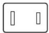
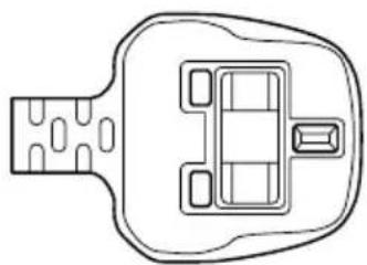
natural_image
Top-down line drawing of a vehicle head and seat (no text or symbols)BS approvedUL approved
Australia Europe
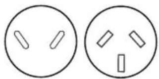
natural_image
Two identical circular diagrams with internal rectangular cutouts, no text or symbols present.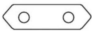
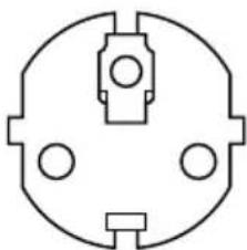
natural_image
Simple line drawing of a symmetrical mechanical or electrical component with three circular holes and a central square (no text or symbols)appropriate agency
AS approved Approved by the
Canada
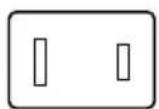
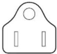
CSA approved
Appendix G
TOSHIBA Anti-theft Protection Timer
This feature allows you to set up a timer-activated BIOS password that will prevent unauthorised system access in the event of theft.
When the time limit is exceeded, you are required to provide the Password or fingerprint authentication for the BIOS and Hard Disk Drive to gain access to the system.
To set permissions and limits for the TOSHIBA Anti-theft Protection Timer please use the TOSHIBA Password Utility.
The settings can only be activated or modified by a user with supervisor authority. If the supervisor password is not set, click on the Set button in Supervisor Password from the supervisor tab in TOSHIBA Password Utility and set the password on the dialog screen that appears.
Then, click on the Set button in TOSHIBA Anti-theft Protection Timer.
Take the following action if the set limit is exceeded.
If the Supervisor Password is registered but the User Password is not, enter the Supervisor Password to boot up the computer.
If both the Supervisor Password and the User Password are registered, enter either the Supervisor Password, the User Password or the fingerprint authentication to boot up the computer.

The limit counts the number of days from the last time Windows is logged on till the next time the computer is booted up. The range can be set from 1 to 28 days.
- Authentication is required if the computer's clock is significantly modified.
If the Supervisor Password is deleted, this function becomes disabled.
Appendix H
If your computer is stolen

Always take care of your computer and try to prevent it from being stolen. You are the owner of a valuable technical device, which may be highly attractive to thieves, so please do not leave it unattended in a public place. To further help protect against theft, security cables can be bought for use with your notebook when it is being used at home or in the office.
Make a note of your computer's machine type, model number, and serial number, and put it in a safe place. You will find this information on the underside of your notebook. Please also keep the receipt of the computer you purchased.
Should your computer be stolen, however, we'll help you try to find it. Before contacting TOSHIBA, please prepare the following information which is necessary to uniquely identify your computer:
In which country was your computer stolen?
■What type of machine do you have?
■What was the model number (PA number)?
■What was the serial number (8 digits)?
■When was it stolen, i.e. date?
■What is your address, phone, and fax number?
To register the theft on paper, please follow these procedures:
■Fill in the TOSHIBA Theft Registration form (or a copy of it) below.
- Attach a copy of your receipt showing where your computer was purchased.
Either fax or send the receipt and registration form to the address below.
To register the theft online, please follow these procedures:
■Visit www.toshiba-europe.com on the Internet. In the product area, choose Computer Systems.
In the Computer Systems page, open the Support & Downloads menu and choose the Stolen Units Database option.
Your entries are used to track your computer at our service points.
TOSHIBA Theft Registration
Send to: TOSHIBA Europe GmbH
Technical Service and Support
Leibnizstr. 2
93055 Regensburg
Germany
Fax number: +49 (0) 941 7807 921
| Country stolen: | |
| Machine type:(e.g. PORTÉGÉ M400) | |
| Model number:(e.g. PSA50 YXT) |  |
| Serial number:(e.g. 12345678G) |  |
| Date stolen: Year Month Day |  |
Owner's details
| Last name, first name: | |
| Company: | |
| Street: | |
| Postal Code/City: | |
| Country: | |
| Phone: | |
| Fax: |
Glossary
The terms in this glossary cover topics related to this manual. Alternate naming is included for reference.
Abbreviations
AC: alternating current
AGP: accelerated graphics port
ANSI: American National Standards Institute
APM: advanced power manager
ASCII: American Standard Code for Information Interchange
BIOS: basic input output system
CD-ROM: Compact Disc-Read Only Memory
CD-RW: Compact Disc-ReWritable
CMOS: complementary metal-oxide semiconductor
CPU: central processing unit
CRT: cathode ray tube
DC: direct current
DDC: display data channel
DMA: direct memory access
DOS: disk operating system
DVD: digital versatile disc
DVD-R: Digital Versatile Disc-Recordable
DVD-RAM: Digital Versatile Disc-Random Access Memory
DVD-R DL: Digital Versatile Disc Recordable Dual Layer
DVD-ROM: Digital Versatile Disc-Read Only Memory
DVD-RW: Digital Versatile Disc-ReWritable
DVD+R DL: Digital Versatile Disc Recordable Double Layer
ECP: extended capabilities port
FDD: floppy disk drive
FIR: fast infrared
HDD: hard disk drive
IDE: integrated drive electronics
I/O: input/output
IrDA: Infrared Data Association
IRQ: interrupt request
KB: kilobyte
LCD: liquid crystal display
LED: light emitting diode
LSI: large scale integration
MB: megabyte
MS-DOS: Microsoft Disk Operating System
OCR: optical character recognition (reader)
PCB: printed circuit board
PCI: peripheral component interconnect
RAM: random access memory
RGB: red, green, and blue
ROM: read only memory
RTC: real time clock
SCSI: small computer system interface
SIO: serial input/output
SXGA+: super extended graphics array plus
TFT: thin-film transistor
UART: universal asynchronous receiver/transmitter
USB: Universal Serial Bus
UXGA: ultra extended graphics array
VESA: Video Electronic Standards Association
VGA: video graphics array
VRT: voltage reduction technology
WXGA: wide extended graphics array
XGA: extended graphics array
A
adaptor: A device that provides an interface between two dissimilar electronic devices. For example, the AC adaptor modifies the power from a wall outlet for use by the computer. This term also refers to the add-in circuit cards that control external devices, such as video monitors and magnetic tape devices.
allocate: To assign a space or function for a specific task.
alphanumeric: Keyboard characters including letters, numbers and other symbols, such as punctuation marks or mathematical symbols.
alternating current (AC): Electric current that reverses its direction of flow at regular intervals.
analog signal: A signal whose characteristics such as amplitude and frequency vary in proportion to (are an analog of) the value to be transmitted. Voice communications are analog signals.
ANSI: American National Standards Institute. An organization established to adopt and define standards for a variety of technical disciplines. For example, ANSI defined the ASCII standard and other information processing requirements.
antistatic: A material used to prevent the buildup of static electricity.
application: A group of programs that together are used for a specific task such as accounting, financial planning, spreadsheets, word processing and games.
ASCII: American Standard Code for Information Interchange. ASCII code is a set of 256 binary codes that represent the most commonly used letters, numbers, and symbols.
async: Short for asynchronous.
asynchronous: Lacking regular time relationship. As applied to computer communications, asynchronous refers to the method of transmitting data that does not require a steady stream of bits to be transmitted at regular time intervals.
B
backup: A duplicate copy of files kept as a spare in case the original is destroyed.
batch file: A file that can be executed from the system prompt containing a sequence of operating system commands or executable files.
binary: The base two number system composed of zeros and ones (off or on), used by most digital computers. The right-most digit of a binary number has a value of 1, the next a value of 2, then 4, 8, 16, and so on. For example, the binary number 101 has a value of 5. See also ASCII.
BIOS: Basic Input Output System. The firmware that controls data flow within the computer. See also firmware.
bit: Derived from "binary digit," the basic unit of information used by the computer. It is either zero or one. Eight bits is one byte. See also byte.
board: A circuit board. An internal card containing electronic components, called chips, which perform a specific function or increase the capabilities of the system.
boot: Short for bootstrap. A program that starts or restarts the computer. The program reads instructions from a storage device into the computer's memory.
bps: Bits per second. Typically used to describe the data transmission speed of a modem.
buffer: The portion of the computer's memory where data is temporarily stored. Buffers often compensate for differences in the rate of flow from one device to another.
bus: An interface for transmission of signals, data or electric power.
byte: The representation of a single character. A sequence of eight bits treated as a single unit; also the smallest addressable unit within the system.
C
cache memory: High speed memory which stores data that increases processor speed and data transfer rate. When the CPU reads data from main memory, it stores a copy of this data in cache memory. The next time the CPU needs that same data, it looks for it in the cache memory rather than the main memory, which saves time. The computer has two cache levels. Level one is incorporated into the processor and level two resides in external memory.
capacity: The amount of data that can be stored on a magnetic storage device such as a floppy disk or hard disk. It is usually described in terms of kilobytes (KB), where one KB = 1024 bytes and megabytes (MB), where one MB = 1024 KB.
card: Synonym for board. See board.
CardBus: An industry standard bus for 32-bit PC cards.
CD-ROM: A Compact Disc-Read Only Memory is a high capacity disc that can be read from but not written to. The CD-ROM drive uses a laser, rather than magnetic heads, to read data from the disc.
CD-R: A Compact Disc-Recordable disc can be written once and read many times. See also CD-ROM.
CD-RW: A Compact Disc-ReWritable disc can be rewritten many times. See also CD-ROM.
character: Any letter, number, punctuation mark, or symbol used by the computer. Also synonymous with byte.
chassis: The frame containing the computer.
chip: A small semiconductor containing computer logic and circuitry for processing, memory, input/output functions and controlling other chips.
CMOS: Complementary Metal-Oxide Semiconductor. An electronic circuit fabricated on a silicon wafer that requires very little power. Integrated circuits implemented in CMOS technology can be tightly packaged and are highly reliable.
cold start: Starting a computer that is currently off (turning on the power).
COM1, COM2, COM3 and COM4: The names assigned to the serial and communication ports.
commands: Instructions you enter at the terminal keyboard that direct the actions of the computer or its peripheral devices.
communications: The means by which a computer transmits and receives data to and from another computer or device. See parallel interface; serial interface.
compatibility: 1) The ability of one computer to accept and process data in the same manner as another computer without modifying the data or the media upon which it is being transferred.
2) the ability of one device to connect to or communicate with another system or component.
components: Elements or parts (of a system) which make up the whole (system).
computer program: A set of instructions written for a computer that enable it to achieve a desired result.
computer system: A combination of hardware, software, firmware, and peripheral components assembled to process data into useful information.
configuration: The specific components in your system (such as the terminal, printer, and disk drives) and the settings that define how your system works. You use the HW Setup program to control your system configuration.
control keys: A key or sequence of keys you enter from the keyboard to initiate a particular function within a program.
controller: Built-in hardware and software that controls the functions of a specific internal or peripheral device (e.g. keyboard controller).
co-processor: A circuit built into the processor that is dedicated to intensive math calculations.
CPS: Characters Per Second. Typically used to indicate the transmission speed of a printer.
CPU: Central Processing Unit. The portion of the computer that interprets and executes instructions.
CRT: Cathode Ray Tube. A vacuum tube in which beams projected on a fluorescent screen-producing luminous spots. An example is the television set.
cursor: A small, blinking rectangle or line that indicates the current position on the display screen.
D
data: Information that is factual, measurable or statistical that a computer can process, store, or retrieve.
data bits: A data communications parameter controlling the number of bits (binary digits) used to make up a byte. If data bits = 7 the computer can generate 128 unique characters. If data bits = 8 the computer can generate 256 unique characters.
DC: Direct Current. Electric current that flows in one direction. This type of power is usually supplied by batteries.
default: The parameter value automatically selected by the system when you or the program do not provide instructions. Also called a preset value.
delete: To remove data from a disk or other data storage device. Synonymous with erase.
device driver: A program that controls communication between a specific peripheral device and the computer. The CONFIG.SYS file contains device drivers that MS-DOS loads when you turn the computer on.
dialog box: A window that accepts user input to make system settings or record other information.
disk drive: The device that randomly accesses information on a disk and copies it to the computer's memory. It also writes data from memory to the disk. To accomplish these tasks, the unit physically rotates the disk at high speed past a read-write head.
disk storage: Storing data on magnetic disk. Data is arranged on concentric tracks much like a phonograph record.
display: A CRT, LCD, or other image producing device used to view computer output.
documentation: The set of manuals and/or other instructions written for the users of a computer system or application. Computer system documentation typically includes procedural and tutorial information as well as system functions.
DOS: Disk Operating System. See operating system.
driver: A software program, generally part of the operating system, that controls a specific piece of hardware (frequently a peripheral device such as a printer or mouse).
DVD-R (+R, -R): A Digital Versatile Disc-Recordable disk can be written once and read many times. The DVD-R drive uses a laser to read data from the disc.
DVD-RAM: A Digital Versatile Disc-Random Access Memory is a high-capacity, high performance disc that lets you store large volumes of data. The DVD-ROM drive uses a laser to read data from the disc.
DVD-R DL: A disc having two layers on one side with the DVD-R storage capacity about 1.8 times larger than before. The DVD-RW drive uses a laser to read data from the disc.
DVD-ROM: A Digital Versatile Disc-Read Only Memory is a high capacity, high performance disc suitable for play back of video and other high-density files. The DVD-ROM drive uses a laser to read data from the disc.
DVD-RW (+RW, -RW): A Digital Versatile Disc-ReWritable disc can be rewritten many times.
DVD+R DL: A disc having two layers on one side with the DVD+R storage capacity about 1.8 times larger than before. The DVD-RW drive uses a laser to read data from the disc.
E
echo: To send back a reflection of the transmitted data to the sending device. You can display the information on the screen, or output it to the printer, or both. When a computer receives back data it transmitted to a CRT (or other peripheral device) and then retransmits the data to printer, the printer is said to echo the CRT.
erase: See delete.
escape: 1) A code (ASCII code 27), signaling the computer that what follows are commands; used with peripheral devices such as printers and modems.
2) A means of aborting the task currently in progress.
escape guard time: A time before and after an escape code is sent to the modem which distinguishes between escapes that are part of the transmitted data, and escapes that are intended as a command to the modem.
execute: To interpret and execute an instruction.
Extended Capability Port: An industry standard that provides a data buffer, switchable forward and reverse data transmission, and run length encoding (RLE) support.
F
fast infrared: An industry standard that enables cableless infrared serial data transfer at speeds of up to 4 Mbps.
file: A collection of related information; a file can contain data, programs, or both.
fingerprint sensor: The fingerprint sensor compares and analyzes the unique characteristics in a fingerprint.
firmware: A set of instructions built into the hardware which controls and directs a microprocessor's activities.
floppy disk: A removable disk that stores magnetically encoded data.
floppy disk drive (FDD): An electromechanical device that reads and writes to floppy disks.
Fn-esse: A TOSHIBA utility that lets you assign functions to hot keys.
folder: An icon in Windows used to store documents or other folders.
format: The process of readying a blank disk for its first use. Formatting establishes the structure of the disk that the operating system expects before it writes files or programs onto the disk.
function keys: The keys labeled F1 through F12 that tell the computer to perform certain functions.
G
gigabyte (GB): A unit of data storage equal to 1024 megabytes. See also megabyte.
graphics: Drawings, pictures, or other images, such as charts or graphs, to present information.
H
hard disk: A non-removable disk usually referred to as drive C. The factory installs this disk and only a trained engineer can remove it for servicing. Also called fixed disk.
hard disk drive (HDD): An electromechanical device that reads and writes a hard disk. See also hard disk.
hardware: The physical electronic and mechanical components of a computer system: typically, the computer itself, external disk drives, etc. See also software and firmware.
hertz: A unit of wave frequency that equals one cycle per second.
hexadecimal: The base 16 numbering system composed of the digits 0 through 9 and the letters A, B, C, D, E, and F.
host computer: The computer that controls, regulates, and transmits information to a device or another computer.
hot key: The computer's feature in which certain keys in combination with the extended function key, Fn, can be used to set system parameters, such as speaker volume.
HW Setup: A TOSHIBA utility that lets you set the parameters for various hardware components.
I
icon: A small graphic image displayed on the screen or in the indicator panel. In Windows, an icon represents an object that the user can manipulate.
i.LINK (IEEE1394): This port enables high-speed data transfer directly from external devices such as digital video cameras.
infrared port: A cableless communications port capable of using infrared signals to send serial data.
input: The data or instructions you provide to a computer, communication device or other peripheral device from the keyboard or external or internal storage devices. The data sent (or output) by the sending computer is input for the receiving computer.
instruction: Statements or commands that specify how to perform a particular task.
interface: 1) Hardware and/or software components of a system used specifically to connect one system or device to another.
2) To physically connect one system or device to another to exchange information.
3) The point of contact between user, the computer, and the program, for example, the keyboard or a menu.
interrupt request: A signal that gives a component access to the processor.
I/O: Input/output. Refers to acceptance and transfer of data to and from a computer.
I/O devices: Equipment used to communicate with the computer and transfer data to and from it.
IrDA 1.1: An industry standard that enables cableless infrared serial data transfer at speeds of up to 4 Mbps.
J
jumper: A small clip or wire that allows you to change the hardware characteristics by electrically connecting two points of a circuit.
K
K: Taken from the Greek word kilo, meaning 1000; often used as equivalent to 1024, or 2 raised to the 10th power. See also byte and kilobyte.
KB: See kilobyte.
keyboard: An input device containing switches that are activated by manually pressing marked keys. Each keystroke activates a switch that transmits a specific code to the computer. For each key, the transmitted code is, in turn, representative of the (ASCII) character marked on the key.
kilobyte (KB): A unit of data storage equal to 1024 bytes. See also byte and megabyte.
L
level 2 cache: See cache.
Light Emitting Diode (LED): A semiconductor device that emits light when a current is applied.
Liquid Crystal Display (LCD): Liquid crystal sealed between two sheets of glass coated with transparent conducting material. The viewing-side coating is etched into character forming segments with leads that extend to the edge of the glass. Applying a voltage between the glass sheets alters the brightness of the liquid crystal.
LSI: Large Scale Integration.
1) A technology that allows the inclusion of up to 100,000 simple logic gates on a single chip.
2) An integrated circuit that uses large scale integration.
M
main board: See motherboard.
megabyte (MB): A unit of data storage equal to 1024 kilobytes. See also kilobyte.
megahertz: A unit of wave frequency that equals 1 million cycles per second. See also hertz.
menu: A software interface that displays a list of options on the screen. Also called a screen.
microprocessor: A hardware component contained in a single integrated circuit that carries out instructions. Also called the central processing unit (CPU), one of the main parts of the computer.
mode: A method of operation, for example, the boot mode, Standby Mode or the Hibernation Mode.
modem: Derived from modulator/demodulator, a device that converts (modulates) digital data for transmission over telephone lines and then converts modulated data (demodulates) to digital format where received.
monitor: A device that uses rows and columns of pixels to display alphanumeric characters or graphic images. See also CRT.
motherboard: A name sometimes used to refer to the main printed circuit board in processing equipment. It usually contains integrated circuits that perform the processor's basic functions and provides connectors for adding other boards that perform special functions. Sometimes called a main board.
MP3: An audio compression standard that enables high-quality transmission and real-time playback of sound files.
N
non-system disk: A formatted floppy disk you can use to store programs and data but you cannot use to start the computer. See system disk.
nonvolatile memory: Memory, usually read-only (ROM), that is capable of permanently storing information. Turning the computer's power off does not alter data stored in nonvolatile memory.
numeric keypad overlay: A feature that allows you to use certain keys on the keyboard to perform numeric entry, or to control cursor and page movement.
0
OCR: Optical Character Recognition (reader). A technique or device that uses laser or visible light to identify characters and input them into a storage device.
online state: A functional state of a peripheral device when it is ready to receive or transmit data.
operating system: A group of programs that controls the basic operation of a computer. Operating system functions include interpreting programs, creating data files, and controlling the transmission and receipt (input/output) of data to and from memory and peripheral devices.
output: The results of a computer operation. Output commonly indicates data.
1) printed on paper, 2) displayed at a terminal, 3) sent through the serial port of internal modem, or 4) stored on some magnetic media.
P
parallel interface: Refers to a type of information exchange that transmits information one byte (8 bits) at a time. See also serial interface.
parity: 1) The symmetrical relationship between two parameter values (integers) both of which are either on or off; odd or even; 0 or 1. 2) In serial communications, an error detection bit that is added to a group of data bits making the sum of the bits even or odd. Parity can be set to none, odd, or even.
password: A unique string of characters used to identify a specific user. The computer provides various levels of password protection such as user, supervisor and eject.
pel: The smallest area of the display that can be addressed by software. Equal in size to a pixel or group of pixels. See pixel.
peripheral component interconnect: An industry standard 32-bit bus.
peripheral device: An I/O device that is external to the central processor and/or main memory such as a printer or a mouse.
pixel: A picture element. The smallest dot that can be made on a display or printer. Also called a pel.
plug and play: A capability with Windows that enables the system to automatically recognize connections of external devices and make the necessary configurations in the computer.
port: The electrical connection through which the computer sends and receives data to and from devices or other computers.
Power Saver Utility: A TOSHIBA utility that lets you set the parameters for various power-saving functions.
printed circuit board (PCB): A hardware component of a processor to which integrated circuits and other components are attached. The board itself is typically flat and rectangular, and constructed of fiberglass, to form the attachment surface.
program: A set of instructions a computer can execute that enables it to achieve a desired result. See also application.
prompt: A message the computer provides indicating it is ready for or requires information or an action from you.
R
Radio frequency interference (RFI) shield: A metal shield enclosing the printed circuit boards of the printer or computer to prevent radio and TV interference. All computer equipment generates radio frequency signals. The FCC regulates the amount of signals a computing device can allow past its shielding. A Class A device is sufficient for office use. Class B provides a more stringent classification for home equipment use. TOSHIBA portable computers comply with Class B computing device regulations.
Random Access Memory (RAM): High speed memory within the computer circuitry that can be read or written to.
restart: Resetting a computer without turning it off (also called "warm boot" or "soft reset"). See also boot.
RGB: Red, green, and blue. A device that uses three input signals, each activating an electron gun for a primary additive color (red, green, and blue) or port for using such a device. See also CRT.
RJ11: A modular telephone jack.
RJ45: A modular LAN jack.
ROM: Read Only Memory: A nonvolatile memory chip manufactured to contain information that controls the computer's basic operation. You cannot access or change information stored in ROM.
S
SCSI: Small Computer System Interface is an industry standard interface for connection of a variety of peripheral devices.
SD card: Secure Digital cards are flash memory widely used in a variety of digital devices such as digital cameras and Personal Digital Assistants.
serial communications: A communications technique that uses as few as two interconnecting wires to send bits one after another.
serial interface: Refers to a type of information exchange that transmits information sequentially, one bit at a time. Contrast: Parallel interface.
SIO: Serial Input/Output. The electronic methodology used in serial data transmission.
soft key: Key combinations that emulate keys on the IBM keyboard, change some configuration options, stop program execution, and access the numeric keypad overlay.
software: The set of programs, procedures and related documentation associated with a computer system. Specifically refers to computer programs that direct and control the computer system's activities. See also hardware.
stop bit: One or more bits of a byte that follow the transmitted character or group codes in asynchronous serial communications.
subpixel: Three elements, one red, one green and blue (RGB), that make up a pixel on the color LCD. The computer sets subpixels independently, each may emit a different degree of brightness. See also pixel.
synchronous: Having a constant time interval between successive bits, characters or events.
system disk: A disk that has been formatted with an operating system. For MS-DOS the operating system is contained in two hidden files and the COMMAND.COM file. You can boot a computer using a system disk. Also called an operating system disk.
T
terminal: A typewriter-like keyboard and CRT display screen connected to the computer for data input/output.
TFT display: A liquid crystal display (LCD) made from an array of liquid crystal cells using active-matrix technology with thin film transistor (TFT) to drive each cell.
Touch Pad: A pointing device integrated into the TOSHIBA computer palm rest.
TTL: Transistor-transistor logic. A logic circuit design that uses switching transistors for gates and storage.
U
Universal Serial Bus: This serial interface lets you communicate with several devices connected in a chain to a single port on the computer.
V
VGA: Video Graphics Array is an industry standard video adaptor that lets you run any popular software.
volatile memory: Random access memory (RAM) that stores information as long as power is supplied to the computer.
W
warm start: Restarting or resetting a computer without turning it off.
window: A portion of the screen that can display its own application, document or dialog box. Often used to mean a Microsoft Windows window.
Wireless LAN: Local Area Network (LAN) through wireless communication.
write protection: A method for protecting a floppy disk from accidental erasure.
Index
A
AC adaptor 4
additional 17, 14
connecting 7
Anti-theft Protection Timer 1
ASCII characters 9
B
Battery
charging 10
extending life 13
indicator 11, 4
location 6
monitoring capacity 12
real time clock 4, 7
safety precautions 7
save mode 11
types 5
Battery charger 17
Battery pack 4, 7
additional 14
replacing 14
Bluetooth 8, 45
Bluetooth Stack for Windows by
Toshiba 14
problems 18
Boot Priority 3
Bridge media slot 7, 4
C
Cache memory 3
Cleaning the computer 49
Cooling vents 3
D
DC IN indicator 11, 4
Display 6
automatic power off 10
brightness decrease 5
brightness increase 5
controller 1
hinge 8
opening 10
screen 9
DLA for TOSHIBA 15, 35
Docking interface 7, 8
Documentation list 2
DVD Super Multi drive 5
location 4
problems 10
using 23
writing 29
DVD-ROM / CD-R/RW drive
using 23
writing 27
DVD-ROM&CD-R/RW drive 5
location 4
problems 9
E
Environment 1
Equipment checklist 1
Equipment setup
general conditions 2
placement 3
Ergonomics
lighting 4
seating and posture 4
work habits 5
External monitor 7, 5, 21
problems 16
F
Fingerprint Sensor
location 8
problems 14
using 13
Floppy disk care 38
Fn + Ctrl (enhanced keyboard simulation) 3
Fn + Enter 3
Fn + Esc (sound mute) 3
Fn + F1 (instant security) 4
Fn + F10 (Arrow mode) 3
Fn + F11 (Numeric mode) 3
Fn + F12 (ScrLock) 3
Fn + F2 (power save mode) 4
Fn + F3 (standby) 4
Fn + F4 (hibernation) 4
Fn + F5 (display selection) 4
Fn + F6 (internal LCD screen brightness decreases) 5
Fn + F7 (internal LCD screen brightness increases) 5
Fn + F8 (wireless setting) 5
Fn + F9 (Touch Pad) 5
Fn + space (LCD screen resolution selection) 6
Fn + Tab (Optical media drive power icon) 6
Function keys 2
G
Graphics controller 6
H
Hard disk drive 4
automatic power off 10
Installing 18
Removing 17
HDD indicator 11
HDD Protection 12
Heat dispersal 11, 53
Hibernation 12, 4
Hot keys 10
display selection 4
instant security 4
Internal LCD screen brightness decrease 5
Internal LCD screen brightness in-
crease 5
power save mode 4
sound mute 3
standby 4
wireless setting 5
HW Setup 13
accessing 1
Boot priority 3
CPU 6
device config 7
display 2
general 2
keyboard 6
LAN 7
USB 7
window 1
|
i.LINK 7, 4, 21
connecting 22
disconnecting 23
precautions 22
problems 17
Indicators 11, 4
K
Keyboard 6, 1
emulating enhanced keyboard 2
Fn Sticky key 6
Function keys F1...F12 2
Hot keys 3
problems 7
typewriter keys 1
Windows special keys 7
Keypad overlay 11, 7
Arrow mode 7
Numeric mode 8
temporarily using normal keyboard
(overlay on) 8
temporarily using overlay (overlay off) 8
turning on the overlays 7
L
LAN 8, 48
cable types 48
connecting 48
disconnecting 49
jack 6
LAN active indicator 6
Link indicator 6
problems 18
M
Media care 38, 4
Card care 4
CD/DVDs 38
floppy disks 38
Memory card care 4
Memory 3
expansion 17, 9
installing 10
problems 15
Memory Stick/Memory Stick Pro 6
inserting 7
problems 12
removing 7
Modem 8, 41
connecting 42
disconnecting 44
jack 5
problems 17
properties menu 42
region selection 41
Moving the computer 50
P
Password
power on 11
problems 7
starting the computer by 18
Supervisor 18
user 16
PC card 7, 2
inserting 2
location of slot 3
problems 11
removing 3
Pointing Device
Reserve Pen 7, 2
Tablet PC Pen 2
Touch Pad 7, 9, 1
Touch Pad control buttons 9, 1
Touch Pad location 8
using 1
Ports
Docking 7
external monitor 7
i.LINK 7
USB 7
Power
button location 8
conditions 1
hibernation mode 13
indicators 4
panel on/off 11, 20
shut down mode (boot mode) 11
standby mode 12
system auto off 20
turning off 11
turning on 10
Problems
AC power 5
Analyzing symptoms 2
Battery 6
Bluetooth 18
DVD Super Multi drive 10
DVD-ROM&CD-R/RW drive 9
External monitor 16
Fingerprint sensor 14
Hard disk drive 8
Hardware and system checklist 3
i.LINK 17
Internal LCD display panel 8
Keyboard 7
LAN 18
Memory expansion 15
Memory Stick/Memory Stick Pro 12
Modem 17
Overheating power down 5
Password 7
PC card 11
Pointing device 13
Power 4
Real Time Clock 7
SD card 12
Self test 4
Sound system 16
System start-up 4
TOSHIBA support 20
USB 15
USB floppy disk drive 11
USB mouse 14
Wireless LAN 18
xD picture card 12
Processor 3
R
RecordNow! 14, 33
Restarting the computer 15
S
SD card 4
formatting 6
inserting 4
problems 12
removing 5
SD memory card 6
SDIO card 6
Security lock 18
attaching 24
location 3
Slice Expansion battery pack 17, 6
Soft keys
enhanced keyboard 2
Enter 3
right Ctrl key 3
ScrLock 3
Sound system 39
headphone jack 7, 2
microphone 2
microphone jack 7, 2
mute hot keys 3
problems 16
Stereo speakers 9
volume control 2
Standby 12
setting 12
System automatic 10
T
TOSHIBA Assist 14
TOSHIBA Assist button 10
TOSHIBA ConfigFree 15
TOSHIBA Controls 13
TOSHIBA Express Port Replicator 17, 23
TOSHIBA Mic Effect 15
TOSHIBA Mobile Extension 14
TOSHIBA PC Diagnostic Tool 14
TOSHIBA Power Saver 13
TOSHIBA Presentation button 10
TOSHIBA SD Memory Boot Utility 14
TOSHIBA Theft Registration 2
TOSHIBA Zooming Utility 14
TV 21
U
Ultra Slim Bay 4
changing modules 21
HDD adaptor (Black) 19
location of slot 4
options 19
USB 7
location 5
problems 15
USB floppy disk drive
problems 11
using 20
V
Video modes 1
Video RAM 3
Volume control 2
W
Wireless communication 44
indicator 11, 47
Wireless communication switch 9, 1, 47
Wireless LAN 8, 44
problems 18
X
xD picture card 8
inserting 8
removing 8