Echo Express SE III-R - Uncategorized Sonnet - Free user manual and instructions
Find the device manual for free Echo Express SE III-R Sonnet in PDF.


User questions about Echo Express SE III-R Sonnet
0 question about this device. Answer the ones you know or ask your own.
Ask a new question about this device
Download the instructions for your Uncategorized in PDF format for free! Find your manual Echo Express SE III-R - Sonnet and take your electronic device back in hand. On this page are published all the documents necessary for the use of your device. Echo Express SE III-R by Sonnet.
USER MANUAL Echo Express SE III-R Sonnet
text_image
ion Chassis Click the Video Tab to V Installation InstructionQuick Start Guide Video Available Online!
Visit
http://www.sonnettech.com/product/echoexpress3r.html
Click the Video Tab to View Installation Instructions

THUNDERBOLT.
PCI
EXPRESS®

Mac
For
Windows
SONN ^®
SIMPLY FAST www.sonnettech.com
Contents
1 Introduction and System Requirements 1
2 Echo Express III-R Description 2
3 PCIe Card Installation and Chassis Setup Steps
4 Verify Connections Using OS X System Information 8
A - Verify Echo Express III-R is Recognized
B - Verify Installed Cards are Recognized
5 Tips, General Information, and Known Issues 9
Tips, General Information
Known Issues
6 Specifications, Precautions, FCC Compliance, and Support Information 10
Specifications
Safety Precautions
FCC Compliance
Contacting Customer Service
Visit Our Website
A BNC Connector Installation Steps A
This page left intentionally blank
Chapter 1 – Introduction and System Requirements
Congratulations on your purchase! The Echo Express III-R is a Thunderbolt 2-to-PCI Express card expansion chassis. Through its PCIe slots, you may connect three expansion cards to your iMac ^® , Mac ^® mini, Mac Pro ^® , MacBook Air ^® , or MacBook Pro ^® with Thunderbolt technology to expand its capabilities in ways never before possible! With its Windows ^® support, the Echo Express III-R offers you a handy way to connect expansion cards to your desktop or laptop PC with Thunderbolt technology.
Mac Compatibility
• Mac computer with a Thunderbolt 2 or Thunderbolt port
- OS X® 10.8.5 or later
Windows Compatibility
- Windows PC with a Thunderbolt 2 or Thunderbolt port*
- Windows 10, 8, 7
System Requirements
While the Echo Express III-R chassis requires no drivers, the expansion cards you install do; Thunderbolt-compatible drivers to enable it to work properly through the Thunderbolt interface are required. More information on which cards are compatible with Echo Express III-R is available at: http://sonnettech.com/support/charts/thunderbolt/index.html
* To support more than two PCIe controllers, Windows requires a Thunderbolt 2 interface in both the computer and the expansion chassis. Note that some PCIe cards have a bridge to multiple controllers, so it is possible for a single dual-controller PCIe card to reach the limit if not connected via Thunderbolt 2. Not all Mac-compatible PCIe cards are also compatible with Windows.
natural_image
Technical line drawings of two server rack units with ventilation grilles and drive bays (no text or symbols)Chapter 2 – Echo Express III-R Description
natural_image
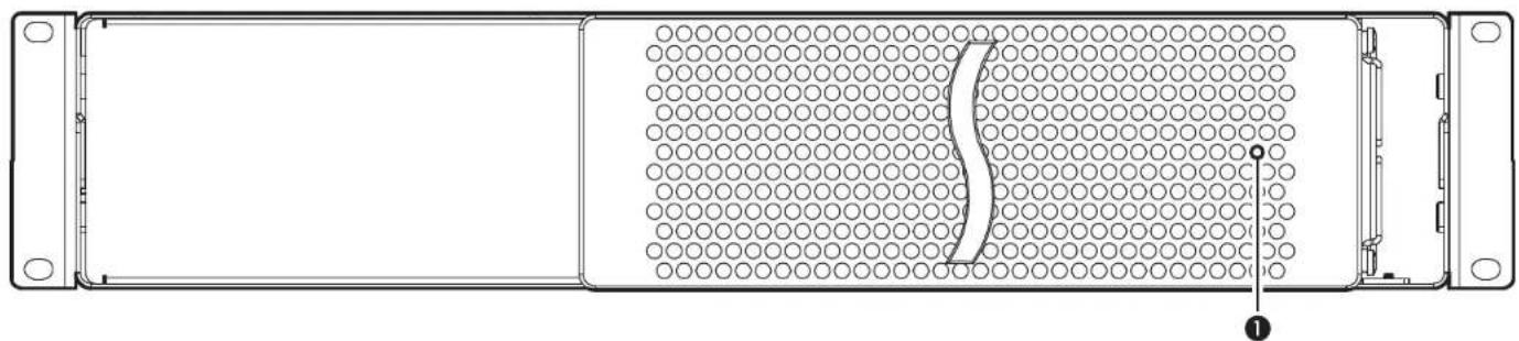
Technical line drawing of a rectangular electronic device with a grid pattern and a curved cutout (no text or symbols)1 - Power Indicator LED
This lights when: the Echo Express III-R is powered, the Thunderbolt cable between the chassis and your computer is plugged in securely, and the computer powered on.
text_image
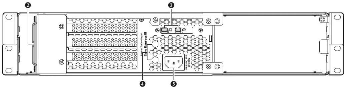
Sensor Technologies Elto Express III 11-200V, 2.6A Hi: 40-50 ④ ⑤2 - Temperature-Controlled Fans
These provide cooling for the installed PCIe cards and the chassis' supporting Thunderbolt circuitry. They operate at a whisper when the cards are running cool, and automatically speed up in steps as the temperature rises. Do not block the vent holes to prevent overheating.
Connect a Thunderbolt cable between either port and your computer's Thunderbolt port (or other Thunderbolt device in the chain connected to the computer); the other may be used to connect to another Thunderbolt device.
These accommodate the installation of BNC connectors like those used for HD/SDI output for the RED ROCKET-X transcoding card, or for MADI and word clock input and output from cards like RME's HDSPe MADI FX.
Connect the included AC power cable here.
3 - Thunderbolt Ports
4 - BNC Connector Mounting Holes
5 - Power Input Socket
Chapter 2 – Echo Express III-R Description
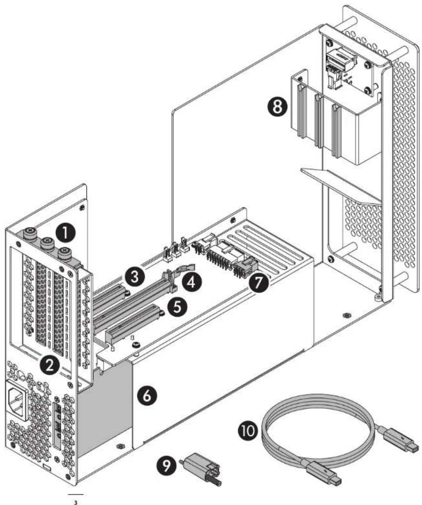
Inner Assembly
1 - PCIe Card Bracket Locking Plate This secures installed PCIe cards and port access covers.
2 - Port Access Covers
These cover openings in the chassis when PCIe slots are unoccupied.
3 - Slot 1
This is an x8 electrical (x8 mechanical) PCIe 2.0 slot. It is also compatible with PCIe 1.1 and 3.0 cards.
4 - Slot 2
This is an x8 electrical (x16 mechanical) PCIe 2.0 slot. It is also compatible with PCIe 1.1 and 3.0 cards.
5 - Slot 3
This is an x4 electrical (x8 mechanical) PCIe 2.0 slot. It is also compatible with PCIe 1.1 and 3.0 cards.
6 - Thunderbolt Interface Card
This card is installed in its own slot and may not be moved to another slot.
7 - 6-Pin Auxiliary Power Connector
Plugged into this connector is the auxiliary power cable for cards requiring extra power.
8 - PCIe Card Guides
When installing full-length cards, use these to support and secure the cards.
9 - Thunderbolt Connector Retainer Clip
This secures a Thunderbolt connector plugged into the Echo chassis' Thunderbolt port to prevent accidental cable disconnection. This clip is not compatible with optical Thunderbolt cables.
10- Thunderbolt Cable
Connect this cable between the Echo chassis and your computer (or other Thunderbolt device in the chain connected to the computer).
text_image
Technical diagram of an electronic device showing labeled components including power connectors, connectors, and a cable.Chapter 3 – PCIe Card Installation and Chassis Setup Steps
- Remove the Echo Express III-R from its packaging, and then set it on a flat, level surface.
-
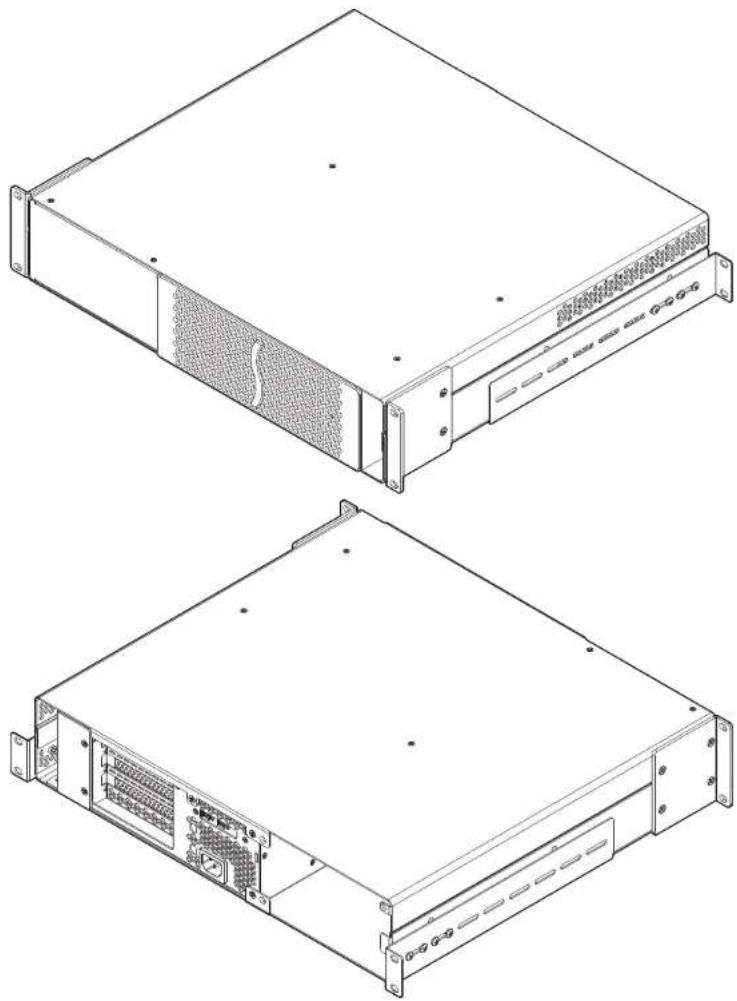
If necessary, adjust or remove the rackmount extension rails by removing the four screws securing each one to the side of the enclosure. As necessary, set the rails in place and secure them to the enclosure with no fewer than two screws on each rail (Figure 1).
-
Using a Phillips screwdriver, remove and set aside the five screws securing the inner assembly to the rackmount enclosure (Figure 2).
-
Push the back of the inner assembly into the enclosure, and then gently pull out the inner assembly through the front of the enclosure (Figure 2).
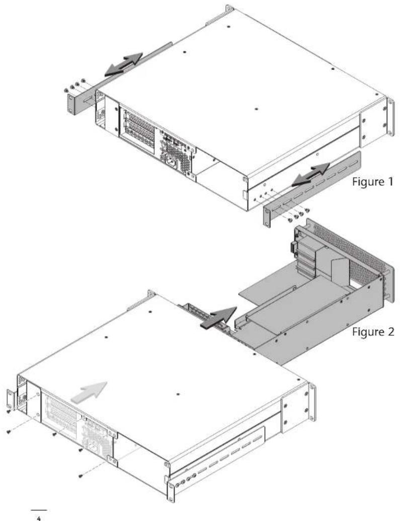
text_image
Figure 1 Figure 2Chapter 3 – PCIe Card Installation and Chassis Setup Steps
- OPTIONAL STEP: If you are going to install an optional Sonnet mobile rack device mounting kit into the III-R, remove and set aside the six screws securing the blank plate inside the enclosure, and then remove and set aside the cover plate (Figure 3).
- OPTIONAL STEP: Due to its size and weight, we recommend that you install the empty rackmount enclosure now. If you don't have full access to the back of the rack into which you'll install the III-R, or you are installing an optional mobile rack device mounting kit into a III-R that will reside in a mobile cart or rack, wait to install the assembled III-R until instructed to do so.

ortNote: To avoid damaging components due to static electricity discharge, wear an antistatic wrist strap while working the Echo Express chassis.
- Turn the inner assembly so the PCIe slots are facing up (Figure 4).
- Loosen all three thumbscrews of the PCIe card bracket locking plate, and then remove and set it aside (Figure 4).
- Remove and set aside the port access covers (Figure 4).

WARNING: When handling computer products, take care to prevent components from being damaged by static electricity; avoid working eted areas. Handle expansion cards only by their edges and avoiding connector traces and component pins. Also, avoid touching the basis' circuit boards and any of its components.
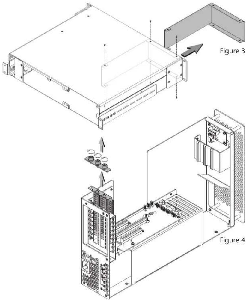
text_image
Figure 3 Figure 4Chapter 3 – PCIe Card Installation and Chassis Setup Steps
- OPTIONAL STEP: If you are installing a PCIe card which requires additional power and must be connected to auxiliary power, locate the wire harness connected the 6-pin connector indicated in the graphic to the right (Figure 5). Remove the cable twist tie securing the wire harness, and move the loose connector aside for later connection. Otherwise, go to the next step.

ortNote: If you are installing an Avid Pro Tools|HDX PCIe
card, you will need to disconnect the Echo chassis' auxiliary power
arness plugged into the 6-pin connector indicated in Figure 5. and
e it with the one included with the Avid card.
- OPTIONAL STEP: If you are installing BNC connectors into the chassis' mounting holes, skip to the appendix at the end of the document for instructions. Otherwise, go to the next step.
- Remove a PCIe card from its packaging, handling the card by its edges and without touching any components or gold connector pins.

ortNote: If you are installing an x8 PCIe 1.1 card like the
original Red Rocket (not Red Rocket-X), or certain 10 Gigabit
net cards, installing it into slot 3 may result in reduced performance.
We recommend you install it into either slot 1 or 2 for best performance.
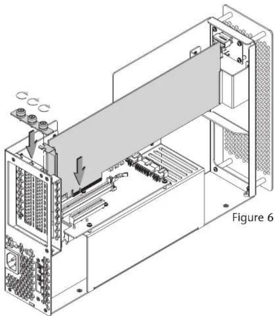
- Line up the card's connector with the slot, and then gently but firmly press the card straight into the slot; do not rock the card or force the card into the slot. If you encounter excessive resistance, check the card's connector and the slot for damage, and then try inserting the card again (Figure 6).
- Repeat steps 12 and 13 as necessary with any remaining cards.
- If you installed a card which requires auxiliary power, connect the auxiliary power connector to it now. If you installed cables with BNC connectors into the chassis, connect them to the card you installed.
- If there are any unoccupied slots, install the port access covers you removed previously (Figure 6).
- Secure the cards and port access covers using the previously-removed PCIe card bracket locking plate (Figure 6).
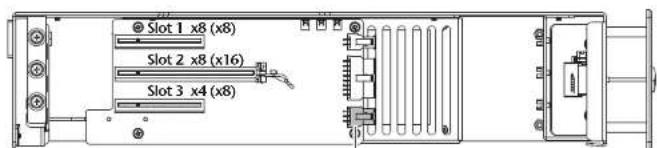
text_image
Slot 1 x8 (x8) Slot 2 x8 (x16) Slot 3 x4 (x8)6-pin connector
Figure 5
natural_image
Technical diagram of an internal server rack with cooling fans and ventilation slots (no text or labels)Chapter 3 – PCIe Card Installation and Chassis Setup Steps
- OPTIONAL STEP: If you are also installing a Sonnet mobile rack device mounting kit, refer to its user's guide now for instructions about installing it and the inner assembly. Otherwise, go to the next step.
- Gently push the inner assembly back inside the rackmount enclosure (Figure 7).
- Secure the inner assembly to the rackmount enclosure using the five screws you removed previously (Figure 7).
- If you haven't already installed the Echo Express III-R into its rack, do so now.

Support Note: Sonnet's ThunderLok™ Thunderbolt connector retainer clip secures the included Thunderbolt cable to the Echo to prevent accidental disconnects. Although it is compatible with copper Thunderbolt cables like Apple's, it is not compatible with Thunderbolt cables.
To attach the clip to the cable, remove them from their packaging, and then insert the connector into the connector clip as shown (Figure 8). Note that the connector will pass all the way through the clip; when you connect the cable to the chassis, the clip will secure the cable.
- Connect the included Thunderbolt cable between either Thunderbolt port on the Echo chassis and a Thunderbolt port on your computer, or other Thunderbolt device in the chain connected to the computer (Figure 8). Secure the retainer clip to the chassis if you attached it. If you are daisy chaining additional Thunderbolt devices, connect another Thunderbolt cable between the downstream device and the open Thunderbolt port on the Echo chassis.
- Connect interface cables between devices, PCIe cards, and computer as necessary.
- Connect the included power cord between a wall outlet or power strip and the Echo chassis' power socket. Note that the power indicator on the Echo Express III-R will not light until the computer, and any other Thunderbolt device connected between it and the Echo chassis, is powered on.
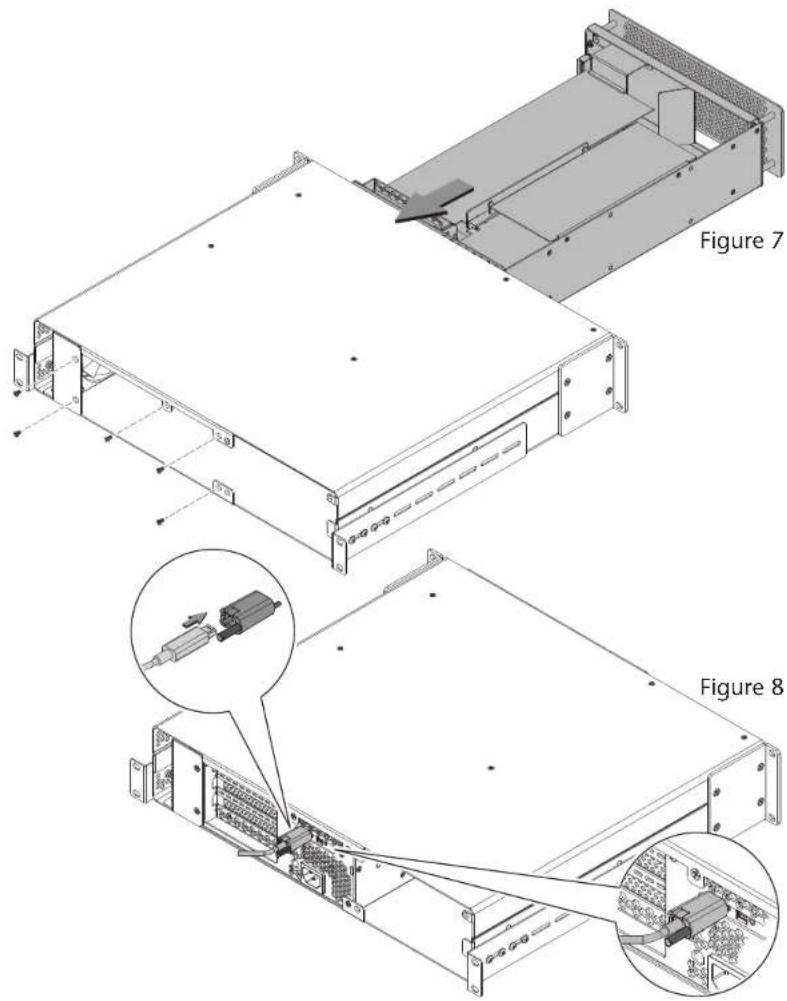
text_image
Figure 7 Figure 8Chapter 4 – Verify Connections Using OS X System Information
A - Verify the Echo Express III-R is Recognized
- With the Echo chassis powered and connected to the computer, turn on the computer.
- From the Apple menu, select About This Mac; the System Information application will launch.
- When the About This Mac window opens, click More Info; a summary of specifications will appear.
- Click System Report; a full report window will appear.
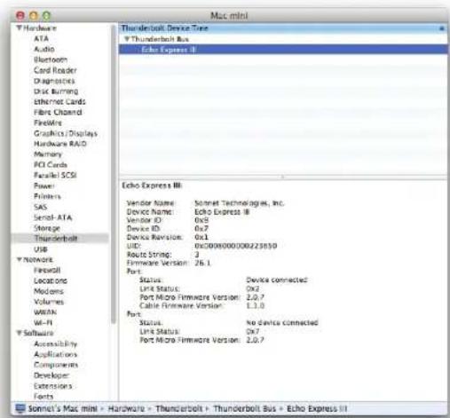
- In the System Information window, click Thunderbolt under the Hardware header in the left column (Figure 10).
- In the top right column under the Thunderbolt Device Tree header, you will see the computer, followed by "Echo Express III" (Figure 10).

Support Note: If "Echo Express III" is not listed, disconnect and reconnect the Thunderbolt cable between the computer and Echo. Note that it is not necessary to shut down the computer before connecting and reconnecting the cable.
B - Verify Installed Cards are Recognized
- When a card is installed into one of Echo chassis' PCIe slot(s), the PCIe slot (listed as a port), the Status should appear as connected.
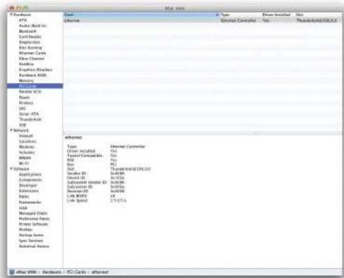
- Click PCI Cards under the Hardware header in the left column (Figure 11).
- At the top of the right column, installed cards are listed. By selecting a card at the top, detailed information is listed. You should see "Yes" next to Driver Installed and Tunnel Compatible, otherwise the card or driver may not be Thunderbolt compatible (Figure 11).

Support Note: While Echo Express expansion chassis require no drivers, installed cards require Thunderbolt-compatible drivers to their use.
text_image
Mac mini Hardware ATA Audio Bluetooth Card Reader Diagnostics Disk Burning Ethernet Cards Fiber Chond FireEye Graphics Displays Hardware RAID Memory PCI Cards Parallel SCSI Power Printers SAS Serial-ATA Storage Thunderbolt USB VMware Fireroll Locations Modems Volumes WWAN MI-FI Software Accessibility Applications Components Developer Extensions Fonts Thunderbolt Device Time Thunderbolt Bus Echo Express II Echo Express III: Vendor Name: Sonnet Technologies, Inc. Device Name: Echo Express III Vendor ID: 0x8 Device ID: 0x7 Device Revision: 0x1 UIC: 0x0000000000223650 Route String: 3 Firmware Version: 26.1. Port: Status: Device connected Link Status: 0x2 Port Micro Firmware Version: 2.0.7 Cable Firmware Version: 1.3.3 Port: Status: No device connected Link Status: 0x7 Port Micro Firmware Version: 2.0.7Figure 10
text_image
File Edit View Insert Help External Control No Temporary Data External Control External Control External Control External Control External Control External Control External Control External Control External Control External Control External Control External Control External Control External Control External Control External Control External Control External Control External Control External Control External Control External Control External Control External Control External Control External Control External Control External Control External Control External Control External Control External Control External Control External ControlFigure 11
Chapter 5 – Tips, General Information, and Known Issues
TIPS, GENERAL INFORMATION
Keeping the Cards Cool
With its optimized airflow design and temperature-controlled fans providing cooling at all times, the Echo Express III-R provides adequate cooling for the installed cards. Do not operate the Echo Express III-R with the inner assembly removed, and do not block any of the vents! Otherwise, the installed cards and Echo Express' components may overheat.
Hot Plugging the Echo Express III-R - Mac Users
When certified Thunderbolt-compatible cards (used with Thunderbolt-compatible drivers) are installed in Echo Express III-R, you may connect and disconnect the chassis while the computer is on. Of course, if you have anything connected to the cards, such as storage devices, cameras, etc., follow proper procedures for disconnecting those devices before unplugging the Echo Express chassis.
There's No Need to Unplug the Power Cable
Because the Echo Express III-R automatically powers on and off with the computer to which it's connected, there's no power switch, nor is there any need to disconnect the power cable under normal use.
Power Indicator LED Operation
Because the Echo Express III-R automatically powers on and off with the computer to which it's connected, its power indicator LED only turns on when the computer is on, and turns off when the computer is sleeping or powered off.
Connecting Additional Thunderbolt Devices
You may connect up to six Thunderbolt devices total in a daisy chain, including the Apple Thunderbolt Display.
Using Expansion Cards Without Drivers
Some Thunderbolt-compatible expansion cards, like Sonnet's Presto ^™ Gigabit Pro PCIe and Sonnet's Tempo ^™ SATA Pro 6Gb eSATA cards, use drivers built into the OS.
Replacing Cards or Adding Cards After Initial Installation
If you decide to replace or add a card to the Echo Express chassis after the initial setup, shut down the computer, and then disconnect the power cord and Thunderbolt cables before installing a card.
PCIe CARDS ARE NOT HOT-PLUGGABLE!
Never install a PCIe card into Echo Express while it is connected to a computer or power outlet! If you do, you risk injury, and damage to the card, chassis, and computer.
KNOWN ISSUES
Not all PCIe Cards Will Perform at 100%
Thunderbolt 2's PCIe bandwidth is limited to 20Gbps. While many cards will operate at full performance, some may not due to the fact they require more bandwidth than Thunderbolt is capable of delivering.
OS X Updates May Break Compatibility
Specific device drivers that work under one version of OS X may not work under a later version. Before updating to the latest OS, we recommend that you contact your PCIe cards' manufacturers to verify that the existing drivers work with the new OS version. Note that other software updates for the computer may also break compatibility.
Some Devices' Performance May be Affected by Where They Are Connected in a Thunderbolt Chain
However small, Thunderbolt introduces latency to a device chain. If you expand with additional Thunderbolt expansion chassis, you may need to experiment with which cards work better in chassis closer to or farther from the computer in the chain.
Thunderbolt Support Under Windows is Incomplete At the time of this writing, Intel and Microsoft have not settled on a certification standard for Thunderbolt devices under Windows. The main unresolved issues are how hot-plugging support and sleep mode support for Thunderbolt devices are handled. Support for these features exists under OS X, but is still in development under Windows.
While Thunderbolt-compatible cards will function in your Echo expansion chassis when attached to your computer at boot, we cannot guarantee how the Windows driver will respond to hot-plugging of the Thunderbolt cable after boot or how it will operate when returning from sleep. While we do expect these issues to be resolved in the future, at the present they are not.
Chapter 6 – Specifications, Precautions, FCC Compliance, and Support Information
Specifications
| External Connectors • Two Thunderbolt• One power (C14-type) | |
| Internal Connectors 6-pin | Mini-Fit Jr |
| Expansion Slots • One x8 | mechanical (x8 electrical) PCIe 2.0• One x16 mechanical (x8 electrical) PCIe 2.0• One x8 mechanical (x4 electrical) PCIe 2.0 |
| PCIe Cards Supported • | One full-length, full-height, double-width PCIe card, plus one single-width card or• Three full-length, full-height, single-width PCIe cards |
| Compatible PCIe Cards See Sonnet Website (www.sonnettech.com) | |
| Power Supply Universal 300W, 115-230V AC, 50-60 Hz(1) | |
| Operating Temperatures 0°C to 35°C (32°F to 95°F) | |
| Dimensions WxDxH | 19 x 16 x 3.48 in.(48.26 x 40.6 x 8.85 cm) |
| Weight | 19 lbs(8.6 kg) |
| RoHS Compliant | Yes |
| Package Contents | • Echo Express III-R chassis• Power cord• Thunderbolt cable• ThunderLok Thunderbolt connector retainer clip(2)• User's guide |
- Power supply will operate at 90-115V AC, with linear power deration of 240W-300W over that range.
- Not compatible with optical Thunderbolt cables.
SAFETY PRECAUTIONS
Please read this section carefully before proceeding. These precautions explain the correct and safe use of this device, thereby helping to prevent injury to you or others, and also help you to minimize the risk of damaging the device.
- Do not attempt to modify the enclosure. If this device appears to be malfunctioning, contact your reseller or local distributor.
- Do not drop the chassis; dropping or mishandling chassis may result in a malfunction leaving the product inoperable.
- Do not insert your fingers or foreign objects inside the slot(s).
- Do not expose the device to rain, use it near water or containers that contain liquids which might spill into any openings, or in damp or wet conditions.
- If unusual smells, sounds, or smoke come from the device, or if liquids enter it, unplug it from the electrical outlet immediately.
- Follow the instructions in this manual carefully; contact your reseller or local distributor for additional advice not covered in this User's Guide.
FCC Compliance
Echo Express III complies with Part 15 of the FCC Rules. Operation is subject to the following two conditions: This device may not cause harmful interference, AND this device must accept any interference received, including interference that may cause undesired operation.
Contacting Customer Service
The Sonnet Web site located at www.sonnettech.com has the most current support information and technical updates. Before you call Customer Service, please check our Web site for the latest updates and online support files, and check this User's Guide for helpful information.
When you call Customer Service, have the following information available so the customer service staff can better assist you:
- Product name
• Date and place of purchase - Computer model
- PCIe card models
- Operating system version
- Software/firmware versions
USA Customers
If further assistance is needed, please contact Sonnet
Customer Service at:
Tel: 1-949-472-2772
(Monday–Friday, 7 a.m.–4 p.m. Pacific Time)
E-mail: support@sonnettech.com
For Customers Outside the USA
For support on this product, contact your reseller or local distributor.
Visit Our Web Site
For the most current product information and online support files, visit the Sonnet Web site at www.sonnettech.com/support/. Register your product online at http://registration.sonnettech.com to be informed of future upgrades and product releases.
Appendix A - BNC Connector Installation Steps
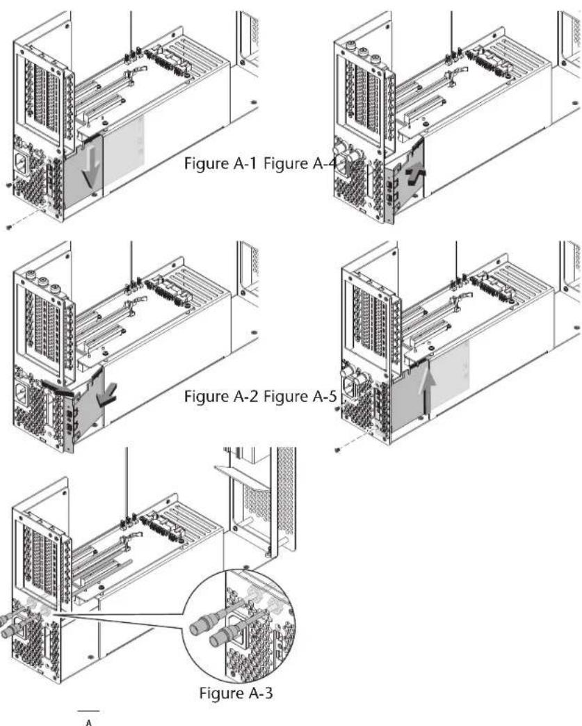
- Remove and set aside the two screws securing the Thunderbolt interface card to the inner assembly (Figure A-1).
- Gently push down on the edge of the card to disengage the card from its slot (Figure A-1).
- Grasping the card by its edges, rotate the card out of the inner assembly, and then pull it out (Figure A-2). Set aside the Thunderbolt interface card on flat surface, component side down.
- Insert the BNC cables through the BNC connector mounting holes in the inner assembly (Figure A-3). Route the cables out over the top of the PCIe slot riser card.
- Slide the connector nuts over the BNC cables, and then secure the connectors to the inner assembly (Figure A-3).
- Grasping the Thunderbolt interface card by its edges, insert the card back into the inner assembly (Figure A-4).
- Line up the card's connector with the slot, and then gently but firmly press the card straight into the slot; do not rock the card or force the card into the slot. If you encounter excessive resistance, check the card's connector and the slot for damage, and then try inserting the card again (Figure A-5).
- Using the two screws you removed previously, secure the Thunderbolt interface card to the inner assembly; do not overtighten the screws (Figure A-5).
- Return to step 12 on page 6 to complete the PCIe card and chassis setup steps.

SIMPLYFAST
www.sonnettech.com
©2015 Sonnet Technologies, Inc. All rights reserved Sonnet, the Sonnet logotype, Simply Fusr, the Simply Fusr logotype, Allegro, Echo, and Tempo are trademarks of Sonnet Technologies, Inc. FireWire, Mac, the Mac logo, and OS X are trademarks of Apple Inc., registered in the United States and other countries. Thunderbolt 2 and the Thunderbolt logo are trademarks of Intel Corporation in the U.S. and/or other countries. Other product names are trademarks of their respective owners. Product specifications subject to change without notice. Printed in the USA. UG-ECHO-EXP3FR-E-F-102715
Statement of Conformity
Sonnet Technologies, Inc.
8 Autry
Irvine, CA 92618
USA
Declare under our sole responsibility that the product(s):
Echo Express III Echo Express III-D Echo Express III-F
Product Name: Product Model(s):
To which this declaration relates is in conformity with the requirements of the following specifications:
ANSI C63.4-2009
FCC 47 CFR Part 15, Subpart B, Class B Digital Device. ICES-003 Issue 5
Supplementary information:
This device complies with part 15 of the FCC Rules. Operation is subject to the following two conditions: (1) This device may not cause harmful interference, and (2) this device must accept any interference received, including interference that may cause undesired operation.
| Signed by or for manufacturer:Name: George SmithTitle: Director of Hardware DevelopmentPlace and Date: Sugar Hill, GA USA, September 22, 2014 |
EC Declaration of Conformity In accordance with EN ISO 17050-1:2004
Sonnet Technologies, Inc.
8 Autry Irvine, CA 92618 USA
Manufacturer's Name:
Manufacturer's Address:
In accordance with Directive(s):
LVD (2006/95/EC).
EMC Directive (2004/108/EC)
hereby declare, that the product
Echo Express III
Echo Express III-D Echo Express III-R
Product Name:
Product Number(s):
Conforms to the following Product Specifications:
Safety: IEC 60950-1:2005/A1:2009, EN 60950-1:2006/A11:2009/A1:2010/A12:2011/AC:2011
EN 55022:2010
EN 55024:2010
EN 61000-3-2:2006 w/A1:2009 and A2:2009
EN 61000-3-3:2008
EMC:
I hereby declare that the equipment named above has been designed to comply with the relevant sections of the above referenced specifications. The unit complies with all applicable Essential Requirements of the Directives.
George Smith, Director of Hardware Development
Sugar Hill, GA USA
September 22, 2014