
AL2416W - Screen ACER - Free user manual and instructions
Find the device manual for free AL2416W ACER in PDF.


User questions about AL2416W ACER
0 question about this device. Answer the ones you know or ask your own.
Ask a new question about this device
Download the instructions for your Screen in PDF format for free! Find your manual AL2416W - ACER and take your electronic device back in hand. On this page are published all the documents necessary for the use of your device. AL2416W by ACER.
USER MANUAL AL2416W ACER
FCC Statement Warning....2
Canadian DOC Notice 2
Important Safety Instructions.... 3
Special Notes on LCD Monitors....3
Chapter 1 Installation .... 4
Unpacking....4
Viewing Angle Adjustment .... 4
Detaching LCD Monitor from Its Stand 4
Interface for Arm Applications....5
Connecting the Display....5
Connecting the AC Power 5
Power Management System....5
Chapter 2 Display Controls....6
General Instructions....6
Front Panel Control 7
How to Adjust a Setting....8
Adjusting the Picture 8
Chapter 3 Technical Information....10
Specifications....10
Standard Timing Table 13
Troubleshooting....15
Preface
This manual is designed to assist users in setting up and using the LCD Monitor. Information in this document has been carefully checked for accuracy; however, no guarantee is given to the correctness of the contents. The information in this document is subject to change without notice. This document contains proprietary information protected by copyright. All rights are reserved. No part of this manual may be reproduced by any mechanical, electronic or other means, in any form, without prior written permission of the manufacturer.
FCC Statement Warning
This equipment has been tested and found to comply with the limits for a Class B digital device, pursuant to Part 15 of the FCC Rules. These limits are designed to provide reasonable protection against harmful interference in a residential installation. This equipment generates, uses, and can radiate radio frequency energy, and if not installed and used in accordance with the instruction, may cause harmful interference to radio communications. However, there is no guarantee that interference will not occur in a particular installation. If this equipment does cause harmful interference to radio or television reception, which can be determined by turning the equipment off and on, the user is encouraged to try to correct the interference by one or more of the following measures:
- Reposition or relocate the receiving antenna.
- Increase the separation between the equipment and the receiver.
- Connect the equipment into an outlet on a circuit different from that to which the receiver is connected.
- Consult the dealer or an experienced monitor technician for help.
Warning
Use only shielded signal cables to connect I/O devices to this equipment. You are cautioned that changes or modifications not expressly approved by the party responsible for compliance could void your authority to operate the equipment.
Canadian DOC Notice

This Class B digital apparatus meets all requirements of the Canadian Interference-Causing Equipment Regulations.
Important Safety Instructions
Please read the following instructions carefully. This manual should be retained for future use.
- To clean LCD Monitor screen;
-- Power off LCD Monitor and unplug the AC Cord.
-- Spray a non-solvent cleaning solution onto a rag.
-- Gently clean the screen with dampened rag.
- Do not place the LCD Monitor near a window. Exposing the monitor to rain water, moisture or sunlight can severely damage it.
- Do not apply pressure to the LCD screen. Excess pressure may cause permanent damage to the display.
- Do not remove the cover or attempt to service this unit by yourself. Servicing of any nature should be performed by an authorized technician.
- Store LCD Monitor in a room with a room temperature of -20^ 60^ (or -4^ 140^ ). Storing the LCD Monitor outside this range could result in permanent damage.
- If any of the following occurs, immediately unplug your monitor and call an authorized technician.
* Monitor to PC signal cable is frayed or damaged.
* Liquid spilled into LCD Monitor or the monitor has been exposed to rain.
* LCD Monitor or the case is damaged.
- Only use the supplied main lead to connect the monitor. For a nominal current up to 6A and a device weight above 3 kg, a line not lighter than H05VV-F, 3G, 0.75 mm ^2 must be used.
Lamp Disposal

LAMP(S) INSIDE THIS PRODUCT CONTAIN MERCURY AND MUST BE RECYCLED OR DISPOSED OF ACCORDING TO LOCAL, STATE OR FEDERAL LAWS. FOR MORE INFORMATION, CONTACT THE ELECTRONIC INDUSTRIES ALLIANCE AT WWW.EIAE.ORG FOR LAMP SPECIFIC DISPOSAL INFORMATION CHECK WWW.LAMPRECYCLE.ORG
Special Notes on LCD Monitors
The following symptoms are normal with LCD monitor and do not indicate a problem.
NOTES
- Due to the nature of the fluorescent light, the screen may flicker during initial use. Turn off the Power Switch and then turn it on again to make sure the flicker disappears.
- You may find slightly uneven brightness on the screen depending on the desktop pattern you use.
- The LCD screen has effective pixels of 99.99% or more. It may include blemishes of 0.01% or less such as a missing pixel or a pixel lit all of the time.
- Due to the nature of the LCD screen, an afterimage of the previous screen may remain after switching the image, when the same image is displayed for hours. In this case, the screen is recovered slowly by changing the image or turning off the Power Switch for hours.
Chapter 1 Installation
Unpacking
Before unpacking the LCD Monitor, prepare a suitable workspace for your Monitor and computer. You need a stable and clean surface near a wall power outlet. Make sure that LCD Monitor has enough space around it for sufficient airflow. Though the LCD Monitor uses very little power, some ventilation is needed to ensure that the Monitor does not become too hot.
After you unpack the LCD Monitor, make sure that the following items were included in the box:
* LCD Monitor
* User's Manual
* Quick Setup Guide
* 1.8M Power Cord
* 1.8M Monitor-to-PC D-SUB Cable
* 1.8M Monitor-to-PC DVI Cable (option)
If you find that any of these items is missing or appears damaged, contact your dealer immediately.
Viewing Angle Adjustment
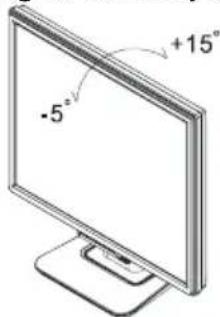
The LCD Monitor is designed to allow users to have a comfortable viewing angle. The viewing angle can be adjusted from -5^ to +15^ . (See fig. 1-1)
text_image
-5° +15°Figure 1-1
Warning
Do not force the LCD Monitor over its maximum viewing angle settings as stated above. Attempting this will result in damaging the Monitor and Monitor stand.
Detaching LCD Monitor from Its Stand
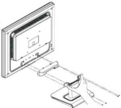
Unscrew screws the swivel base support column and pull down the hinge to release.
natural_image
Technical line drawing of a monitor mounted on a stand with a hand adjusting the handle (no text or symbols)Figure 1-2
Interface for Arm Applications
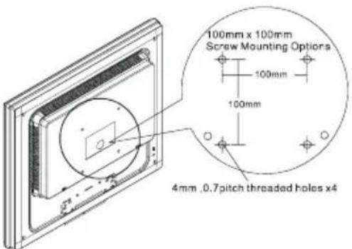
Before installing to mounting device, please refer to Fig.1-2. The rear of this LCD display has four integrated 4 mm, 0.7 pitches threaded nuts, as well as four 5 mm access holes in the plastic covering as illustrated in Figure 1-3. These specifications meet the VESA Flat Panel Monitor Physical Mounting Interface Standard (paragraphs 2.1 and 2.1.3, version 1, dated 13 November 1997).
Connecting the Display
- Power off your computer.
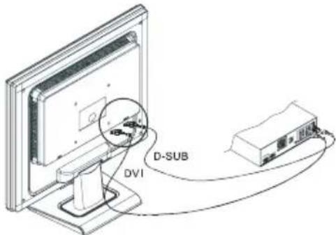
- Connect one end of the signal cable to the LCD Monitor's D-SUB or DVI (option) port.(See Fig 1-4)
- Connect the other end of the signal cable to the D-SUB or DVI (option) port on your PC.
- Make sure connections are secure.
text_image
100mm x 100mm Screw Mounting Options 100mm 100mm 4mm .0.7pitch threaded holes x4Figure 1-3
text_image
D-SUB DVIFigure 1-4
Connecting the AC Power
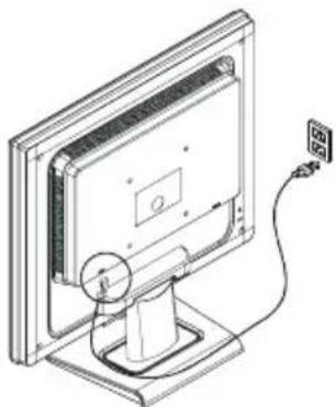
- Connect the power cord to the LCD Monitor. (See Fig. 1-5)
- Connect the power cord to an AC power source.
natural_image
Line drawing of a computer monitor with a cable and power cord, no text or symbols presentFigure 1-5
Power Management System
This LCD Monitor complies with the VESA DPMS (version 1.0) Power Management guidelines. The VESA DPMS provides four power saving modes through detecting a horizontal or vertical sync. signal. When the LCD Monitor is in power saving mode, the monitor screen will be blank and the power LED indicator will light yellow.
Chapter 2 Display Controls
General Instructions
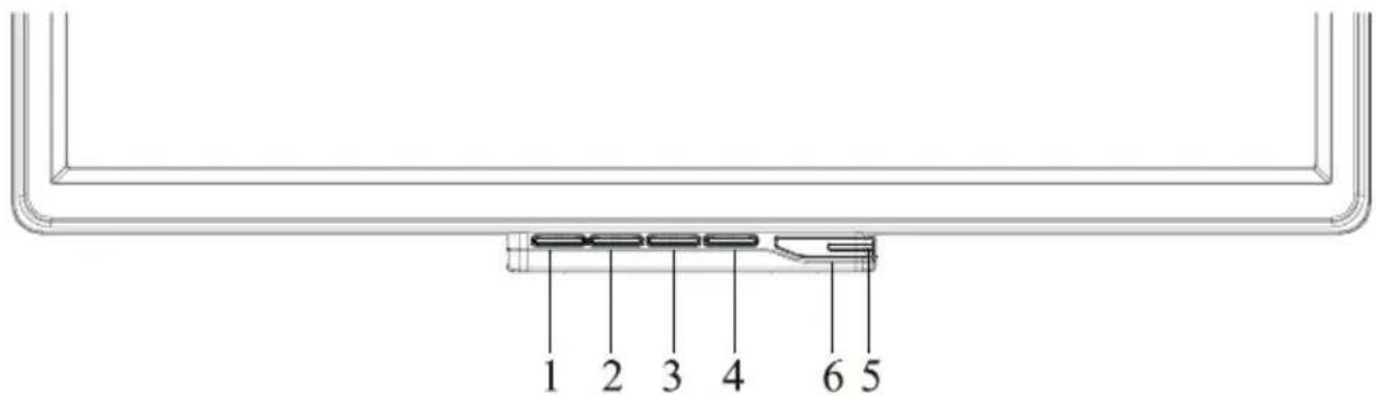
Press the power button to turn the monitor on or off. The other control buttons are located at front panel of the monitor (See Figure 2-1). By changing these settings, the picture can be adjusted to your personal preferences.
● The power cord should be connected.
- Connect the video cable from the monitor to the video card.
- Press the power button to turn on the monitor position. The power indicator will light up.
text_image
1 2 3 4 6 5Figure 2-1
External Controls
| 1 | Auto Adjust Key/Exit 4 MENU/ENTER | ||
| 2 | < 5 LED | ||
| 3 | > 6 | / Power Key |
Front Panel Control
Power Button:
Press this button to turn the monitor ON or OFF, And display the monitor's state.
Power Indicator:
Green — Power On mode.
Orange — off mode
MENU / ENTER :
Activate OSD menu when OSD is OFF or activate/de-activate adjustment function when OSD is ON
<:
Navigate through adjustment icons when OSD is ON or adjust a function when function is activated.
:
Navigate through adjustment icons when OSD is ON or adjust a function when function is activated.
Auto Adjust button / Exit:
-
When OSD menu is in active status, this button will act as EXIT-KEY (EXIT OSD menu).
-
When OSD menu is in off status, press this button for 2 seconds to activate the Auto Adjustment function. The Auto Adjustment function is used to set the HPos, VPos, Clock and Focus.
NOTES
Do not install the monitor in a location near heat sources such as radiators or air ducts, or in a place subject to direct sunlight, or excessive dust or mechanical vibration or shock.
- Save the original shipping carton and packing materials, as they will come in handy if you ever have to ship your monitor.
For maximum protection, repackage your monitor as it was originally packed at the factory.
To keep the monitor looking new, periodically clean it with a soft cloth. Stubborn stains may be removed with a cloth lightly dampened with a mild detergent solution. Never use strong solvents such as thinner, benzene, or abrasive cleaners, since these will damage the cabinet. As a safety precaution, always unplug the monitor before cleaning it.
How to Adjust a Setting
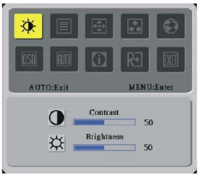
- Press the MENU-button to activate the OSD window.
- Press < or > to select the desired function.
- Press the MENU-button to select the function that you want to adjust.
- Press < or > to change the settings of the current function.
- To exit and save, select the exit function. If you want to adjust any other function, repeat steps 2-4.
text_image
AUTO:Exit MENU:Enter Contrast 50 Brightness 50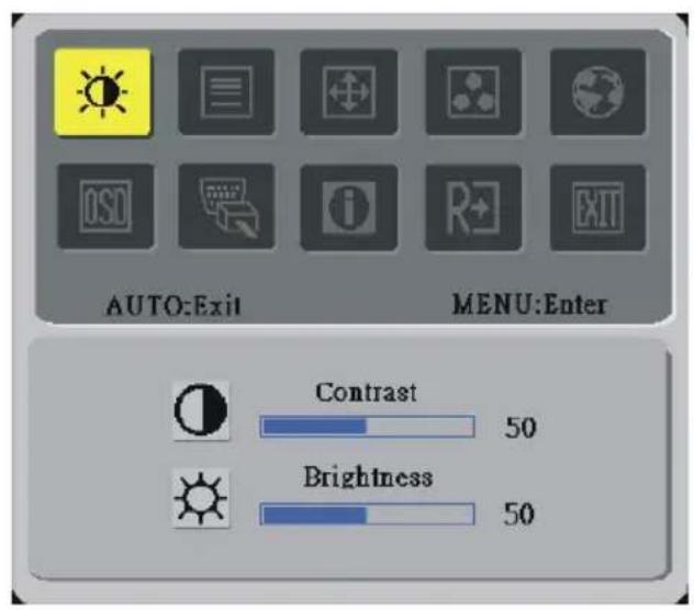
text_image
AUTO:Exit MENU:Enter Contrast 50 Brightness 50(option)
Adjusting the Picture
The descriptions for function control LEDS
| Main Menu Icon | Sub Menu Icon | Sub Menu Item Description |
 |  | Contrast |
 | Brightness | |
 | Focus | |
 | Clock | |
 |  | H. Position |
 | V. Position | |
 | Warm | |
| Cool | ||
 | User / Red | |
 | User / Green | |
 | User / Blue |
 | N/A | English | Multi-language selection. |
| N/A | 繁韻F1V | ||
| N/A | Deutsch | ||
| N/A | Français | ||
| N/A | Español | ||
| N/A | Italiano | ||
| N/A | 简体F1V | ||
| N/A | 日本語 | ||
 | H. Position | Adjust the horizontal position of the OSD. | |
 | V. Position | Adjust the vertical position of the OSD. | |
| OSD Timeout | Adjust the OSD timeout. | ||
 | N/A | Auto Config | Auto Adjust the H/V Position, Focus and Clock of picture. |
 | N/A | Source Change | Analog and Digital source change.(option) |
 | N/A | Information | Show the resolution, H/V frequency and input port of current input timing. |
 | N/A | Reset | Clear each old status of Auto-configuration and set the color temperature to Cool. |
 | N/A | Exit | Save user adjustment and OSD disappear. |
Chapter 3 Technical Information
Specifications
LCD Panel
Size 24"
Display Type Active matrix color TFT LCD
Resolution 1920 x 1200
Display Dot 1920 x (RGB) x 1200
Display Area (mm)(H x V) 518.4 x 324.0
Display Color 16.2M (ture 8bit)
Brightness 500 ^2 (typical) cd/m
Contrast Ratio 1000:1 (typical & I _L =6mA)
Response Time 6ms (Gray to Gray)
Lamp Voltage 1800 Vrms (typical)
Lamp Current 6.0 mA rms. (typical)
Viewing Angle Vertical: 178°
Horizontal: 178°
Video
Input Signal Analogue RGB 0.7Vp-p/ Digital TMDS
Input Impedance 75 Ohm ± 2%
Polarity Positive, Negative
Amplitude 0 - 0.7 ± 0.05 Vp
Multi-mode Supported Horizontal Frequency: 24 \~ 80 KHz
Vertical Frequency: 49 \~ 75 Hz
Control
Power switch On/Off switch with LED indicator
OSD
Brightness Digital
Contrast Digital
Horizontal Position Digital
Vertical Position Digital
Phase Digital
Clock Digital
Display Mode Setup Use EEPROM to save settings in memory
Power Management
| Mode | Power Consumption* | AC Input | LED Color |
| On 110W | maximum 240 VAC Green | ||
| DPMS 2W | maximum 240 VAC Yellow | ||
| Soft switch off | 1W maximum 240 VAC Dark | ||
| Disconnected 2W | maximum 240 VAC | Yellow: Standby, Suspend, OffDark: DC Power off |
* Meeting VESA DPMS requirements measured from AC Input end of AC power cord.
Sync Input
Signal Separate TTL compatible horizontal and vertical synchronization
Polarity Positive and negative
Plug & Play
Supports VESA DDC2B functions
External Connection
Power Input (AC input) AC socket
1.8M with 15-pin D-sub connector
1.8M with DVI connector (option)
Environment
Operating Condition: Temperature 5°C to 40°C/41°F to 104°F
Relative Humidity 20% to 80%
Storage Condition: Temperature -20°C to 60°C/-4°F to140°F
Relative Humidity 5% to 85%
Power Supply (AC Input)
Input Voltage Single phase, 100 240VAC 50 / 60Hz
Input Current 1.2 A maximum
Size and Weight
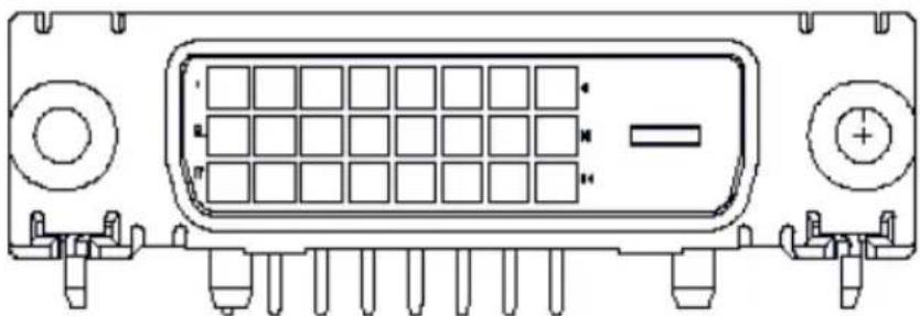
Pin assignment for DVI - D Connector (option):
natural_image
Technical line drawing of an electronic component with no visible text or symbolsStandard Timing Table
If the selected timing is NOT included in table below, this LCD monitor will use the most suitable available timing.
| TIMING | FH(KHZ)FV(HZ) | SYNC POLARITY | TOTAL (DOT/LINE) | ACTIVE (DOT/LINE) | SYNC WIDTH (DOT/LINE) | FRONT PORCH (DOT/LINE) | BACK PORCH (DOT/LINE) | PIXEL FOREQ. (MHZ) |
| 640x350 VGA-350 | 31.469 | + | 800 | 640 | 96 | 10 | ||
| 70.087 | - | 449 | 350 | 2 | 37 | |||
| 640x400 NEC PC9801 | 24.83 | - | 848 | 640 | 64 | 64 | ||
| 56.42 | - | 440 | 400 | 8 | 7 | 25 | ||
| 640x400 VGA-GRAPH | 31.469 | - | 800 | 640 | 96 | 10 | ||
| 70.087 | + | 449 | 400 | 2 | 12 | 35 | ||
| 640x400 NEC PC9821 | 31.5 | - | 800 | 640 | 64 | 16 | 80 | 25.197 |
| 70.15 | - | 449 | 400 | 2 | 13 | 34 | ||
| 640x480 VESA-PAL | 31.469 | - | 800 | 640 | 96 | 16 | 48 | 25.175 |
| 50.030 | - | 629 | 480 | 2 | 62 | 85 | ||
| 640x480 VGA-480 | 31.469 | - | 800 | 640 | 96 | 16 | ||
| 59.94 | - | 525 | 480 | 2 | 10 | 33 | ||
| 640x480 APPLE MAC-480 | 35.00 | - | 864 | 640 | 64 | 64 | ||
| 66.67 | - | 525 | 480 | 3 | 3 | 39 | ||
| 640x480 VESA-480-72Hz | 37.861 | - | 832 | 640 | 40 | 16 | 120 | 31.5 |
| 72.809 | - | 520 | 480 | 3 | 1 | 20 | ||
| 640x480 VESA-480-75Hz | 37.5 | - | 840 | 640 | 64 | 16 | 120 | 31.5 |
| 75 | - | 500 | 480 | 3 | 1 | 16 | ||
| 720x400 VGA-400-TEXT | 31.469 | - | 900 | 720 | 108 | 18 | ||
| 70.087 | + | 449 | 400 | 2 | 12 | 35 | ||
| 832x624 APPLE MAC-800 | 49.725 | - | 1152 | 832 | 64 | 32 | 224 | 57.2832 |
| 74.55 | - | 667 | 624 | 3 | 1 | 39 | ||
| 800x600 SVGA | 35.156 | + | 1024 | 800 | 72 | 24 | 128 | 36 |
| 56.25 | + | 625 | 600 | 2 | 1 | 22 | ||
| 800x600 VESA-600-60Hz | 37.879 | + | 1056 | 800 | 128 | 40 | 88 | 40 |
| 60.317 | + | 628 | 600 | 4 | 1 | 23 | ||
| 800x600 VESA-600-72Hz | 48.077 | + | 1040 | 800 | 120 | 56 | 64 | 50 |
| 72.188 | + | 666 | 600 | 6 | 37 23 | |||
| 800x600 VESA-600-75Hz | 46.875 | + | 1056 | 800 | 80 | 16 | 160 | 49.5 |
| 75 | + | 625 | 600 | 3 | 1 | 21 | ||
| 1024x768 XGA | 48.363 | - | 1344 | 1024 | 136 | 24 | 160 | 65 |
| 60.004 | - | 806 | 768 | 6 | 3 | 29 | ||
| 1024x768 COMPAQ-XGA | 53.964 | + | 1328 | 1024 | 176 | 16 | 112 | 71.664 |
| 66.132 | + | 816 | 768 | 4 | 8 | 36 | ||
| 1024x768 VESA-768-70Hz | 56.476 | - | 1328 | 1024 | 136 | 24 | 144 | 75 |
| 70.069 | - | 806 | 768 | 6 | 3 | 29 | ||
| 1024x768 VESA-768-75Hz | 60.023 | + | 1312 | 1024 | 96 | 16 | 176 | 78.75 |
| 75.029 | + | 800 | 768 | 3 | 1 | 28 | ||
| 1024x768 APPLE MAC-768 1152x864 | 60.24 | - | 1328 | 1024 | 96 | 32 | 176 | 80 |
| 75.02 | - | 803 | 768 | 3 | 3 | 29 | ||
| 54.054 | + | 1480 | 1152 | 96 | 40 | 192 | 80 |
60
| 59.270 | + | 912 | 864 | 3 | 13 | 32 | |||
| 60Hz | 63.851 | + | 1480 | 152 | 96 | 32 | 200 | ||
| 70.012 | + | 912 | 864 | 3 | 1 | 44 | |||
| 1152x864 | 67.50 | + | 1600 | 1152 | 128 | 64 | 256 | 108.00 | |
| 60Hz | 75.00 | + | 900 | 864 | 2 | 2 | 32 | ||
| 1280x960 | 60.00 | + | 1800 | 1280 | 112 | 96 | 312 | 108.00 | |
| 60Hz | 60.00 | + | 1000 | 960 | 3 | 1 | 36 | ||
| 1280x960 | 70.00 | + | 1800 | 1280 | 112 | 96 | 312 | 126.00 | |
| 70Hz | 70.00 | + | 1000 | 960 | 3 | 1 | 36 | ||
| 1280x960 | 75.00 | + | 1800 | 1280 | 112 | 96 | 312 | 135.00 | |
| 75Hz | 75.00 | + | 1000 | 960 | 3 | 1 | 36 | ||
| 1280x1024 | 64 | + | 1688 | 1280 | 112 | 48 | 248 | 108 | |
| VESA-1024-60Hz | 60 | + | 1066 | 1024 | 3 | 1 | 38 | ||
| 1280x1024 | 80 | + | 1688 | 1280 | 144 | 16 | 248 | 135 | |
| VESA-1024-75Hz | 75 | + | 1066 | 1024 | 3 | 1 | 38 | ||
| 1600x1200 | 75 | + | 2160 | 1600 | 192 | 64 | 304 | 162 | |
| VGSA-1200-60Hz | 60 | + | 1250 | 1200 | 50 | 1 | 46 | ||
| 1920x1200 | 74.6 | + | 2592 | 1920 | 200 | 136 | 336 | 193 | |
| VGSA-1200-60Hz | 60 | + | 1245 | 1200 | 6 | 3 | 36 | ||
Note: Mode 640x350, 640x400 and 720x400 will locate on middle position but cannot be expanded to full screen on vertical direction.
Troubleshooting
This LCD Monitor has pre-adjusted using factory standard VGA timings. Due to the output timing differences among various VGA cards in the market, users may initially experience an unstable or unclear display whenever a new display mode or new VGA card is selected.
Attention
This LCD Monitor Supports Multiple VGA Modes.
Refer to the Standard Timing Table for a listing of modes supported by this LCD Monitor.
PROBLEM Picture is unclear and unstable
The picture is unclear and unstable, please perform the following steps :
- Enter PC to "Shut Down Windows" status while you're in MS-Windows environment, except Windows XP. In Windows XP open the specific application where the problems appear.
- Check the screen to see if there's any black vertical stripes appear. If there are, take advantage of the "Clock" function in OSD menu and adjust (by increment or decrement numbers) until those bars disappear.
- Move to "Phase" function in OSD menu again and adjust the monitor screen to its most clear display.
- Click “No” on “Shut Down Windows” and back to the normal PC operating environment.
PROBLEM There is no picture on LCD Monitor
If there's no picture on the LCD Monitor, please perform the following steps:
- Make sure the power indicator on the LCD Monitor is ON, all connections are secured, and the system is running on the correct timing. Refer to Chapter 3 for information on timing.
- Turn off the LCD Monitor and then turn it back on again. If there is still no picture, press the Adjustment Control button several times.
- If step 2 doesn't work, connect your PC system to another external CRT. If your PC system Functions properly with a CRT Monitor but it does not function with the LCD Monitor, the output timing of the VGA card may be out of the LCD's synchronous range. Please change to an alternative mode listed in the Standard Timing Table or replace the VGA card, and then repeat steps 1 and 2.
PROBLEM There is no picture on LCD Monitor
If you have chosen an output timing that is outside of the LCD Monitor's synchronous range (Horizontal: 24 \~ 80 KHz and Vertical: 49 \~ 75 Hz), the OSD will display a “Out of Range” message. Choose a mode that is supported by your LCD Monitor.
Also, if the signal cable is not connected to LCD monitor at all or properly, the monitor screen will display a message “No Input Signal”.