
ARUV168DTE5 - Air-conditioner LG - Free user manual and instructions
Find the device manual for free ARUV168DTE5 LG in PDF.


User questions about ARUV168DTE5 LG
0 question about this device. Answer the ones you know or ask your own.
Ask a new question about this device
Download the instructions for your Air-conditioner in PDF format for free! Find your manual ARUV168DTE5 - LG and take your electronic device back in hand. On this page are published all the documents necessary for the use of your device. ARUV168DTE5 by LG.
USER MANUAL ARUV168DTE5 LG
Please read this installation manual completely before installing the product. Installation work must be performed in accordance with the national wiring standards by authorized personnel only.
Please retain this installation manual for future reference after reading it thoroughly.
MULTI V.5
Cooling Only
Original instruction
TIPS FOR SAVING ENERGY
Here are some tips that will help you minimize the power consumption when you use the air conditioner. You can use your air conditioner more efficiently by referring to the instructions below:
- Do not cool excessively indoors. This may be harmful for your health and may consume more electricity.
- Block sunlight with blinds or curtains while you are operating the air conditioner.
- Keep doors or windows closed tightly while you are operating the air conditioner.
- Adjust the direction of the air flow vertically or horizontally to circulate indoor air.
- Speed up the fan to cool or warm indoor air quickly, in a short period of time.
- Open windows regularly for ventilation as the indoor air quality may deteriorate if the air conditioner is used for many hours.
- Clean the air filter once every 2 weeks. Dust and impurities collected in the air filter may block the air flow or weaken the cooling / dehumidifying functions.
For your records
Staple your receipt to this page in case you need it to prove the date of purchase or for warranty purposes. Write the model number and the serial number here:
Model number :
Serial number :
You can find them on a label on the side of each unit.
Dealer's name :
Date of purchase :
IMPORTANT SAFETY INSTRUCTIONS
READ ALL INSTRUCTIONS BEFORE USING THE APPLIANCE.
Always comply with the following precautions to avoid dangerous situations and ensure peak performance of your product

WARNING
It can result in serious injury or death when the directions are ignored

CAUTION
It can result in minor injury or product damage when the directions are ignored

WARNING
- Installation or repairs made by unqualified persons can result in hazards to you and others.
- The information contained in the manual is intended for use by a qualified service technician familiar with safety procedures and equipped with the proper tools and test instruments.
- Failure to carefully read and follow all instructions in this manual can result in equipment malfunction, property damage, personal injury and/or death.
Installation
- Have all electric work done by a licensed electrician according to "Electric Facility Engineering Standard" and "Interior Wire Regulations" and the instructions given in this manual and always use a special circuit.
- If the power source capacity is inadequate or electric work is performed improperly, electric shock or fire may result.
- Ask the dealer or an authorized technician to install the air conditioner.
- Improper installation by the user may result in water leakage, electric shock, or fire.
• Always ground the product. - There is risk of fire or electric shock.
• Always install a dedicated circuit and breaker. - Improper wiring or installation may cause fire or electric shock.
- For re-installation of the installed product, always contact a dealer or an Authorized Service Center.
- There is risk of fire, electric shock, explosion, or injury.
- Do not install, remove, or re-install the unit by yourself (customer). - There is risk of fire, electric shock, explosion, or injury.
- Do not store or use flammable gas or combustibles near the air conditioner.
- There is risk of fire or failure of product.
- Use the correctly rated breaker or fuse.
- There is risk of fire or electric shock.
- Prepare for strong wind or earthquake and install the unit at the specified place.
- Improper installation may cause the unit to topple and result in injury.
- Do not install the product on a defective installation stand. - It may cause injury, accident, or damage to the product.
- Use a vacuum pump or Inert(nitrogen) gas when doing leakage test or air purge. Do not compress air or Oxygen and do not use Flammable gases. Otherwise, it may cause fire or explosion.
- There is the risk of death, injury, fire or explosion.
- When installing and moving the air conditioner to another site, do not charge it with a different refrigerant from the refrigerant specified on the unit.
- If a different refrigerant or air is mixed with the original refrigerant, the refrigerant cycle may malfunction and the unit may be damaged.
- Do not reconstruct to change the settings of the protection devices.
- If the pressure switch, thermal switch, or other protection device is shorted and operated forcibly, or parts other than those specified by LGE are used, fire or explosion may result.
- Ventilate before operating air conditioner when gas leaked out. - It may cause explosion, fire, and burn.
- Securely install the cover of control box and the panel.
- If the cover and panel are not installed securely, dust or water may enter the outdoor unit and fire or electric shock may result.
- If the air conditioner is installed in a small room, measures must be taken to prevent the refrigerant concentration from exceeding the safety limit when the refrigerant leaks.
- Consult the dealer regarding the appropriate measures to prevent the safety limit from being exceeded. Should the refrigerant leak and cause the safety limit to be exceeded, harzards due to lack of oxygen in the room could result.
Operation
- Do not damage or use an unspecified power cord.
- There is risk of fire, electric shock, explosion, or injury.
- Use a dedicated outlet for this appliance. - There is risk of fire or electrical shock.
- Be cautious that water could not enter the product. - There is risk of fire, electric shock, or product damage.
- Do not touch the power switch with wet hands. - There is risk of fire, electric shock, explosion, or injury.
- When the product is soaked (flooded or submerged), contact an Authorized Service Center.
- There is risk of fire or electric shock.
- Be cautious not to touch the sharp edges when installing. - It may cause injury.
- Take care to ensure that nobody could step on or fall onto the outdoor unit.
- This could result in personal injury and product damage.
- Do not open the inlet grille of the product during operation. (Do not touch the electrostatic filter, if the unit is so equipped.)
- There is risk of physical injury, electric shock, or product failure.
- If the supply cable is damaged, it must be replaced by a special cable or assembly available from the manufacturer of its service agent.

CAUTION
Installation
- Always check for gas (refrigerant) leakage after installation or repair of product.
- Low refrigerant levels may cause failure of product.
- Do not install the product where the noise or hot air from the outdoor unit could damage the neighborhoods.
- It may cause a problem for your neighbors.
- Keep level even when installing the product.
- To avoid vibration or water leakage.
- Do not install the unit where combustible gas may leak.
- If the gas leaks and accumulates around the unit, an explosion may result.
- Use power cables of sufficient current carrying capacity and rating.
- Cables that are too small may leak, generate heat, and cause a fire.
- Do not use the product for special purposes, such as preserving foods, works of art, etc. It is a consumer air conditioner, not a precision refrigeration system.
- There is risk of damage or loss of property.
- Keep the unit away from children. The heat exchanger is very sharp.
- It can cause the injury, such as cutting the finger. Also the damaged fin may result in degradation of capacity.
- When installing the unit in a hospital, communication station, or similar place, provide sufficient protection against noise.
- The inverter equipment, private power generator, high-frequency medical equipment, or radio communication equipment may cause the air conditioner to operate erroneously, or fail to operate. On the other hand, the air conditioner may affect such equipment by creating noise that disturbs medical treatment or image broadcasting.
- Do not install the product where it is exposed to sea wind (salt spray) directly.
- It may cause corrosion on the product. Corrosion, particularly on the condenser and evaporator fins, could cause product malfunction or inefficient operation.
- Means for disconnection must be incorporated in the fixed wiring in accordance with the wiring rules.
Operation
- Do not use the air conditioner in special environments.
- Oil, steam, sulfuric smoke, etc. can significantly reduce the performance of the air conditioner or damage its parts.
- Do not block the inlet or outlet.
- It may cause failure of appliance or accident.
- Make the connections securely so that the outside force of the cable may not be applied to the terminals.
- Inadequate connection and fastening may generate heat and cause a fire.
- Be sure the installation area does not deteriorate with age.
- If the base collapses, the air conditioner could fall with it, causing property damage, product failure, or personal injury.
- Install and insulate the drain hose to ensure that water is drained away properly based on the installation manual.
- A bad connection may cause water leakage.
- Be very careful about product transportation.
- Only one person should not carry the product if it weighs more than 20 kg.
- Some products use PP bands for packaging. Do not use any PP bands for a means of transportation. It is dangerous.
- Do not touch the heat exchanger fins. Doing so may cut your fingers.
-
When transporting the outdoor unit, suspending it at the specified positions on the unit base. Also support the outdoor unit at four points so that it cannot slip sideways.
-
Safely dispose of the packing materials.
- Packing materials, such as nails and other metal or wooden parts, may cause stabs or other injuries.
- Tear apart and throw away plastic packaging bags so that children may not play with them. If children play with a plastic bag which was not torn apart, they face the risk of suffocation.
- Turn on the power at least 6 hours before starting operation.
- Starting operation immediately after turning on the main power switch can result in severe damage to internal parts. Keep the power switch turned on during the operational season.
- Do not touch any of the refrigerant piping during and after operation.
- It can cause a burn or frostbite.
- Do not operate the air conditioner with the panels or guards removed.
- Rotating, hot, or high-voltage parts can cause injuries.
- Do not directly turn off the main power switch after stopping operation.
- Wait at least 5 minutes before turning off the main power switch.
Otherwise it may result in water leakage or other problems. - Auto-addressing should be done in condition of connecting the power of all indoor and outdoor units. Auto-addressing should also be done in case of changing the indoor unit PCB.
- Use a firm stool or ladder when cleaning or maintaining the air conditioner.
- Be careful and avoid personal injury.
- Do not insert hands or other objects through the air inlet or outlet while the air conditioner is plugged in.
- There are sharp and moving parts that could cause personal injury.
TABLE OF CONTENTS
2 TIPS FOR SAVING ENERGY
2 IMPORTANT SAFETY INSTRUCTIONS
5 INSTALLATION PROCESS
5 OUTDOOR UNITS INFORMATION
5 ALTERNATIVE REFRIGERANT R410A
6 SELECT THE BEST LOCATION
6 INSTALLATION SPACE
6 Individual Installation
7 LIFTING METHOD
8 INSTALLATION
8 The location of the Anchor bolts
8 Foundation for Installation
8 Preparation of Piping
10 Plumbing materials and storage methods
11 REFRIGERANT PIPING INSTALLATION
11 Precautions on Pipe connection / Valve operation
11 Connection of Outdoor units
11 Caution
12 PIPE CONNECTIONS BETWEEN INDOOR AND OUTDOOR UNIT
12 Preparation Work
13 Pipe Drawing Out during Single / Series connection
13 Refrigerant piping system
14 Pipe Connection Method between outdoor unit/indoor unit
16 Branch pipe Fitting
18 Distribution Method
18 Vacuum Mode
18 Leak Test and Vacuum drying
19 Refrigerant charging
20 Thermal insulation of refrigerant piping
21 ELECTRICAL WIRING
21 Caution
23 Control box and connecting position of wiring
23 Communication and Power Cables
24 Wiring of main power supply and equipment capacity
24 Field Wiring
29 Checking the setting of outdoor units
30 Automatic Addressing
30 The Procedure of Automatic Addressing
31 High Static Pressure Compensation mode
31 Night Low Noise Function
32 Setting the ODU address
32 Target pressure adjusting
32 Low Ambient Kit
32 High Efficiency Mode (Cooling Operation)
33 Auto Dust Removal Mode
33 Compressor Max. Frequency Limit
33 ODU Fan Max. RPM Limit
34 SLC (Smart Load Control)
34 Humidity Reference
34 Central Control Connection at Indoor Unit side
34 Compressor Input Current Limit
35 Power Consumption Display on wired remote controller
35 Comfort Cooling operation
36 Self-Diagnosis Function
39 CAUTION FOR REFRIGERANT LEAK
39 Introduction
39 Checking procedure of limiting concentration
40 INSTALLATION GUIDE AT THE SEASIDE
40 Model Designation
40 Airborne Noise Emission
INSTALLATION PROCESS
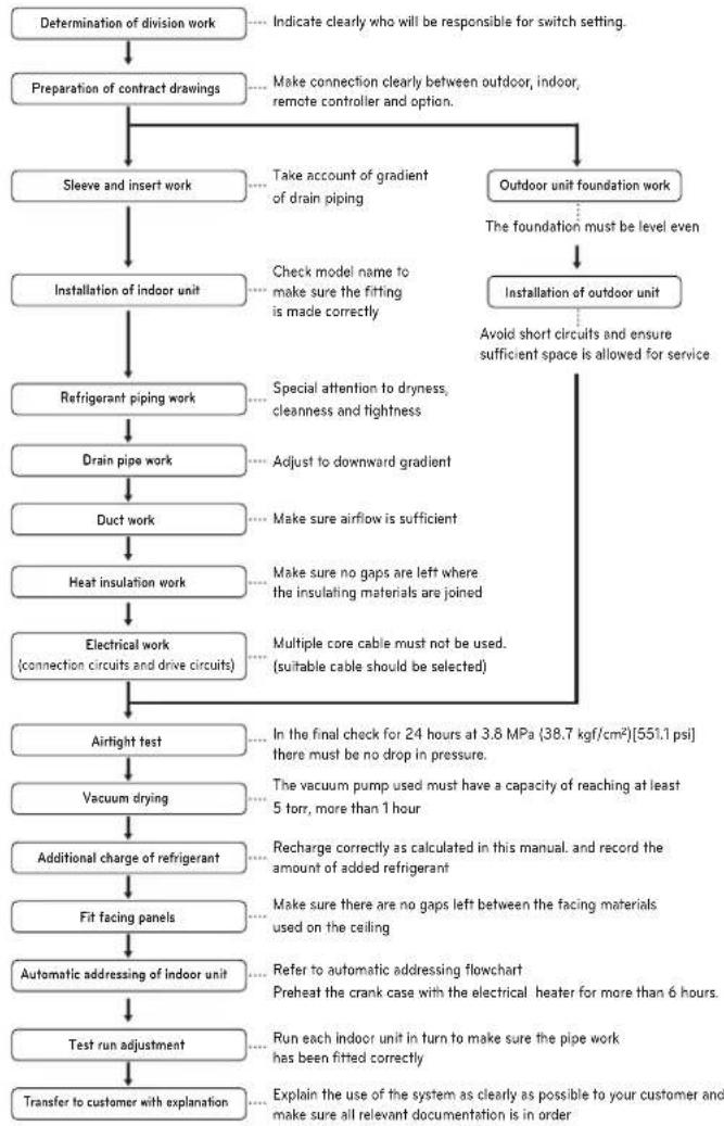
flowchart
graph TD
    A["Determination of division work"] --> B["Preparation of contract drawings"]
    B --> C["Sleeve and insert work"]
    C --> D["Installation of indoor unit"]
    D --> E["Refrigerant piping work"]
    E --> F["Drain pipe work"]
    F --> G["Duct work"]
    G --> H["Heat insulation work"]
    H --> I["Electrical work (connection circuits and drive circuits)"]
    I --> J["Airtight test"]
    J --> K["Vacuum drying"]
    K --> L["Additional charge of refrigerant"]
    L --> M["Fit facing panels"]
    M --> N["Automatic addressing of indoor unit"]
    N --> O["Test run adjustment"]
    O --> P["Transfer to customer with explanation"]

    B --> Q["Make connection clearly between outdoor, indoor, remote controller and option."]
    C --> R["Take account of gradient of drain piping"]
    C --> S["Check model name to make sure the fitting is made correctly"]
    D --> T["Special attention to dryness, cleanliness and tightness"]
    E --> U["Adjust to downward gradient"]
    F --> V["Make sure airflow is sufficient"]
    G --> W["Make sure no gaps are left where the insulating materials are joined"]
    H --> X["Multiple core cable must not be used. (suitable cable should be selected)"]

    J --> Y["In the final check for 24 hours at 3.8 MPa (38.7 kgf/cm²)[551.1 psi"] there must be no drop in pressure.]
    K --> Z["The vacuum pump used must have a capacity of reaching at least 5 torr, more than 1 hour"]
    L --> AA["Recharge correctly as calculated in this manual. and record the amount of added refrigerant"]
    M --> AB["Make sure there are no gaps left between the facing materials used on the ceiling"]
    N --> AC["Refer to automatic addressing flowchart Preheat the crank case with the electrical heater for more than 6 hours."]
    O --> AD["Run each indoor unit in turn to make sure the pipe work has been fitted correctly"]
    P --> AE["Explain the use of the system as clearly as possible to your customer and make sure all relevant documentation is in order"]

CAUTION
- The above list indicates the order in which the individual work operations are normally carried out but this order may be varied where local conditions warrants such change.
- The thickness of the piping should comply with the relevant local and national regulations for the designed pressure 3.8 MPa (551.1 psi).
- Since R410A is a mixed refrigerant, the required additional refrigerant must be charged in its liquid state.(If the refrigerant is charged in its gaseous state, its composition changes and the system will not work properly.)
OUTDOOR UNITS INFORMATION

CAUTION
Combination Ratio(50\~200%)
| Outdoor Number Connection Ratio | |
| Single outdoor units 200 | % |
| Double outdoor units 160 | % |
| Triple outdoor units 130 | % |
| Over the triple unit 130 | % |
Notes: * We can guarantee the operation only within 130 % combination. If you want to connect more than 130 % combination, please contact us and discuss the requirement like below.
- If the operation of indoor unit is more than 130% , the airflow will be operated as low in the all indoor units.
ALTERNATIVE REFRIGERANT R410A
The refrigerant R410A has the property of higher operating pressure in comparison with R22.
Therefore, all materials have the characteristics of higher resisting pressure than R22 ones and this characteristic should also be considered during the installation.
R410A is an azeotrope of R32 and R125 mixed at 50:50, so the ozone depletion potential (ODP) of R410A is 0.

CAUTION
- The wall thickness of the piping should comply with the relevant local and national regulations for the designed pressure 3.8MPa [551.1 psi]
- Since R410A is a mixed refrigerant, the required additional refrigerant must be charged in its liquid state. If the refrigerant is charged in its gaseous state, its composition changes and the system will not work properly.
- Do not place the refrigerant container under the direct rays of the sun to prevent it from exploding.
- For high-pressure refrigerant, any unapproved pipe must not be used.
- Do not heat pipes more than necessary to prevent them from softening.
- Be careful not to install wrongly to minimize economic loss because it is expensive in comparison with R22.
Select space for installing outdoor unit, which will meet the following conditions:
- No direct thermal radiation from other heat sources
- No possibility of annoying neighbors due to noise of unit
- No exposition to strong wind
- With strength which bears weight of unit
• Note that drain flows out of unit when heating
- Because of the possibility of fire, do not install unit to the space where generation, inflow, stagnation, and leakage of combustible gas is expected.
- Avoid unit installation in a place where acidic solution and spray (sulfur) are often used.
- Do not use unit under any special environment where oil, steam and sulfuric gas exist.
- It is recommended to fence round the outdoor unit in order to prevent any person or animal from accessing the outdoor unit.
- If installation site is area of heavy snowfall, then the following directions should be observed.
- Make the foundation as high as possible.
- Fit a snow protection hood.
- Select installation location considering following conditions to avoid bad condition when additionally performing defrost operation.
- Install the outdoor unit at a place well ventilated and having a lot of sunshine in case of installing the product at a place With a high humidity in winter (near beach, coast, lake, etc.)
(Ex : Rooftop where there is always sunshine.)
INSTALLATION SPACE
Individual Installation
During the installation of the unit, consider service, inlet, and outlet acquire the minimum space as shown in the figures below.
Side space should be more than 49 mm for operating of Auto Dust Removal mode.
| Category | Installation Space | Case 1 10 mm( 13/32inch) ≤ Side Space ≤ 49 mm( 13/14inch) | Case 2(Side Space≥49 mm(13/14 inch)) | |
| 4 sides are walls | 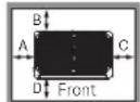 | A≥10 (13/32)B≥300 (11-13/16)C≥10 (13/32)D≥500 (19-11/16) | A≥50 (1-31/32)B≥100 (3-15/16)C≥50 (1-31/32)D≥500(19-11/16) | |
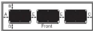 | A≥10 (13/32)B≥300 (11-13/16)C≥10 (13/32)D≥500 (19-11/16)E≥20 (25/32) | A≥50 (1-31/32)B≥100 (3-15/16)C≥50 (1-31/32)D≥500 (19-11/16)E≥100 (3-15/16)F≥500 (19-11/16) | ||
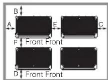 | A≥10 (13/32)B≥300 (11-13/16)C≥10 (13/32)D≥500 (19-11/16)E≥20 (25/32)F≥600 (23-5/8) | A≥50 (1-31/32)B≥100 (3-15/16)C≥50 (1-31/32)D≥500 (19-11/16)E≥100 (3-15/16)F≥500 (19-11/16) | ||
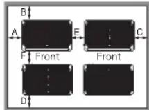 | A≥10 (13/32)B≥300 (11-13/16)C≥10 (13/32)D≥300 (11-13/16)E≥20 (25/32)F≥500 (19-11/16) | A≥50 (1-31/32)B≥100 (3-15/16)C≥50 (1-31/32)D≥100 (3-15/16)E≥100 (3-15/16)F≥500 (19-11/16) | ||
| Rear to Rear | 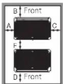 | A≥10 (13/32)B≥500 (19-11/16)C≥10 (13/32)D≥500 (19-11/16)F≥900 (35-7/16) | A≥50 (1-31/32)B≥500 (19-11/16)C≥50 (1-31/32)D≥500 (19-11/16)F≥600 (23-5/8) | |
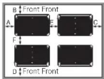 | A≥10 (13/32)B≥500 (19-11/16)C≥10 (13/32)D≥500 (19-11/16)E≥20 (25/32)F≥1200 (47-1/4) | A≥50 (1-31/32)B≥500 (19-11/16)C≥50 (1-31/32)D≥500 (19-11/16)E≥100 (3-15/16)F≥900 (35-7/16) | ||
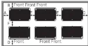 | A≥10 (13/32)B≥500 (19-11/16)C≥10 (13/32)D≥500 (19-11/16)E≥20 (25/32)F≥1800 (70-7/8) | A≥50 (1-31/32)B≥500 (19-11/16)C≥50 (1-31/32)D≥500 (19-11/16)E≥100 (3-15/16)F≥1200 (47-1/4) | ||
| Only 2 sides are walls | 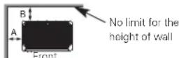 | A≥10 (13/32)B≥300 (11-13/16) | ||
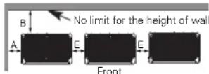 | A≥10 (13/32)B≥300 (11-13/16)E≥20 (25/32) | |||
| Limitations on the height of the wall(Refer to 4 side walls) | 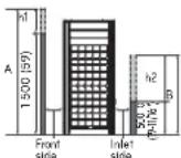 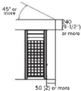 | The height of the wall on the front side must be 1 500 mm (59 inch) or less.The height of the wall on the inlet side must be 500 mm (19-11/16") or less.There is no limit to the wall on Inlet side.If the height of the walls on the front and Inlet side are higher than the limit, there must be additional space on the front and the side.- Additional Space on the front side by 1/2 of h1- Additional Space on the inlet side by 1/2 of h2-h1 = A(Actual height) - 1500 (59 inch)- h2 = B(Actual height) - 500 (19-11/16") | ||
Seasonal wind and cautions in winter
- Sufficient measures are required in a snow areas or severe cold areas in winter so that product can be operated well.
- Get ready for seasonal wind or snow in winter even in other areas.
• Install a suction and discharge duct not to let in snow or rain. - Install the outdoor unit In such a way that it should not come in contact with snow directly. If snow piles up and freezes on the air suction hole, the system may malfunction. If it is installed at snowy area, attach the hood to the system.
- Install the outdoor unit at the higher installation console by 50 cm (19.7 inch) than the average snowfall (annual average snowfall) if it is installed at the area with much snowfall.
-
Where snow accumulated on the upper part of the Outdoor Unit by more than 10 cm (3.9 inch), always remove snow for operation.
-
The height of H frame must be more than 2 times the snowfall and its width shall not exceed the width of the product. (If width of the frame is wider than that of the product, snow may accumulate)
- Don't install the suction hole and discharge hole of the Outdoor Unit facing the seasonal wind.
LIFTING METHOD
- When carrying the suspended, unit pass the ropes under the unit and use the two suspension points each at the front and rear.
• Always lift the unit with ropes attached at four points so that impact is not applied to the unit. - Attach the ropes to the unit at an angle of 40^ or less.
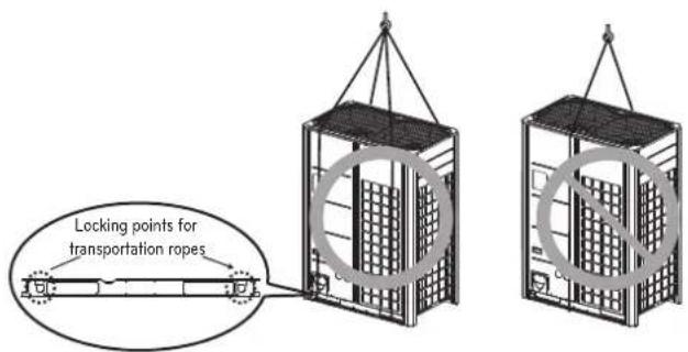
text_image
Locking points for transportation ropes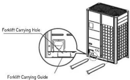
text_image
Forklift Carrying Hole Forklift Carrying GuideCAUTION
Be very careful while carrying the product.
- Do not have only one person carry product if it is more than 20 kg (44 lbs).
- PP bands are used to pack some products. Do not use them as a mean for transportation because they are dangerous.
- Do not touch heat exchanger fins with your bare hands. Otherwise you may get a cut in your hands.
- Tear plastic packaging bag and scrap it so that children cannot play with it. Otherwise plastic packaging bag may suffocate children to death.
- When carrying in Outdoor Unit, be sure to support it at four points. Carrying in and lifting with 3-point support may make Outdoor Unit unstable, resulting in a fall.
- Use 2 belts of at least 8 ~m (26.2 ft) long.
- Place extra cloth or boards in the locations where the casing comes in contact with the sling to prevent damage.
- Hoist the unit making sure it is being lifted at its center of gravity.
INSTALLATION
• Install at places where it can endure the weight and vibration/noise of the outdoor unit.
- The outdoor unit support blocks at the bottom shall have width of at least 100 mm (3-15/16 inch) under the Unit's legs before being fixed.
- The outdoor unit support blocks should have minimum height of 200 mm (7-7/8 inch).
- Anchor bolts must be inserted at least 75 mm (2-15/16 inch).
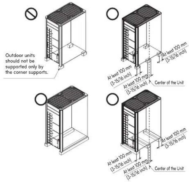
The location of the Anchor bolts
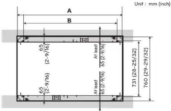
text_image
Unit : mm (inch) A B 65 (2-9/16) At least 65 (2-9/16) 65 (2-9/16) At least 65 (2-9/16) 731 (28-25/32) 760 (29-29/32)| Chassis A [mm (inch)] B [mm (inch)] | |
| UXA 930 (36-5/8) 748 (29-9/20) | |
| UXB 1 240 (47-1/4) 1 040 (40-15/16) |
Foundation for Installation
- Fix the unit tightly with bolts as shown below so that unit will not fall down due to earthquake or gust.
- Use the H-beam support as a base support
- Noise and vibration may occur from the floor or wall since vibration is transferred through the installation part depending on installation status. Thus, use anti-vibration materials (cushion pad) fully (The base pad shall be more than 200 mm (7-7/8 inch)).
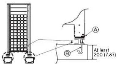
text_image
A B At least 200 (7.87)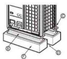
text_image
Technical diagram of a server rack with labeled components including power, socket, and drive slotsⒶ The corner part must be fixed firmly. Otherwise, the support for the installation may be bent.
⑧ Get and use M10 Anchor bolt.
© Put Cushion Pad between the outdoor unit and ground support for the vibration protection in wide area.
⑭ Space for pipes and wiring (Pipes and wirings for bottom side)
© H-beam support
⑤ Concrete support
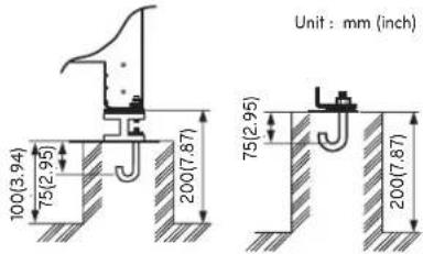
text_image
Unit : mm (inch) 100(3.94) 75(2.95) 200(7.87) 75(2.95) 200(7.87)WARNING
• Install where it can sufficiently support the weight of the outdoor unit.
If the support strength is not enough, the outdoor unit may drop and hurt people.
• Install where the outdoor unit may not fall in strong wind or earthquake.
If there is a fault in the supporting conditions, the outdoor unit may fall and hurt people.
- Please take extra cautions on the supporting strength of the ground, water outlet treatment(treatment of the water flowing out of the outdoor unit in operation), and the passages of the pipe and wiring, when making the ground support.
- Do not use tube or pipe for water outlet in the Base panel. Use drainage instead for water outlet. The tube or pipe may freeze and the water may not be drained.
CAUTION
- Be sure to remove the Pallet(Wood Support) of the bottom side of the outdoor unit Base panel before fixing the bolt. It may cause the unstable state of the outdoor settlement, and may cause freezing of the heat exchanger resulting in abnormal operations.
- Be sure to remove the Pallet(Wood Support) of the bottom side of the outdoor unit before welding. Not removing Pallet(Wood Support) causes hazard of fire during welding.
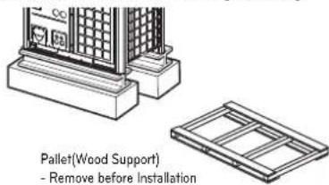
text_image
Pallet(Wood Support) - Remove before InstallationPreparation of Piping
Main cause of gas leakage is defect in flaring work. Carry out correct flaring work in the following procedure.
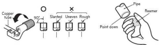
Cut the pipes and the cable
- Use the accessory piping kit or the pipes purchased locally.
- Measure the distance between the indoor and the outdoor unit.
- Cut the pipes a little longer than measured distance.
- Cut the cable 1.5 m (4.92 ft) longer than the pipe length.
text_image
Copper tube 90° Slanted Uneven Rough Point down Pipe ReamerBurrs removal
- Completely remove all burrs from the cut cross section of pipe/tube.
- Put the end of the copper tube/pipe to downward direction as you remove burrs in order to avoid to let burrs drop in the tubing.
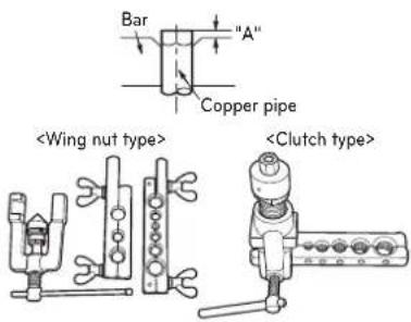
text_image
Bar "A" Copper pipeFlaring work
- Firmly hold copper pipe in a bar with the dimension shown in below table table below.
- Carry out flaring work with the flaring tool.
| Indoor unit [kW/(Btu/h)] | Pipe(mmlnch/l' A (mm) | Inch/l / Wing nut type 'A'(mmlnch/l) / Clutch type | type | |||
| Gas Liquid | Gas Liquid Gas | Liquid | ||||
| <5.6(19 100) | ∅ 12.7 (1/2) | ∅ 6.35 (1/4) | 0.06~0.07(1.6~1.8) | 0.04~0.05(1.1~1.3) | 0~0.02(0~0.5) | |
| <16.0(54 600) | ∅ 15.88 (5/8) | ∅ 9.52 (3/8) | 0.06~0.07(1.6~1.8) | 0.06~0.07(1.5~1.7) | ||
| <22.4(76 400) | ∅ 19.05 (3/4) | ∅ 9.52 (3/8) | 0.07~0.08(1.9~2.1) | 0.06~0.07(1.5~1.7) | ||
Check
- Compare the flared work with figure below.
- If flare is noted to be defective, cut off the flared section and do flaring work again.
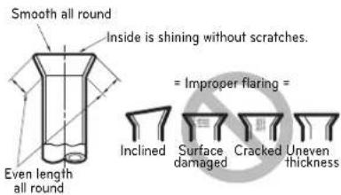
text_image
Smooth all round Inside is shining without scratches. Even length all round = Improper flaring = Inclined Surface damaged Cracked Uneven thicknessFlare shape and flare nut tightening torque
Precautions when connecting pipes
- See the following table for flare part machining dimensions.
- When connecting the flare nuts, apply refrigerant oil to the inside and outside of the flares and turn them three or four times at first. (Use ester oil or ether oil.)
- See the following table for tightening torque.(Applying too much torque may cause the flares to crack.)
- After all the piping has been connected, use nitrogen to perform a gas leak check.
| Pipe size [mm (inch)] | Tightening Torque N·m (lbs·ft) | A [mm (inch)] Flare shape | |
| ∅ 9.52 (3/8) | 38±4 (28±3.0) 12.8 (0 | 5)~13.2 (0.52) | 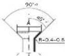 |
| ∅ 12.7 (1/2) | 55±6 (41±4.4) 16.2 (0 | 64)~16.6 (0.65) | |
| ∅ 15.88 (5/8) | 75±7 (55±5.2) 19.3 (0.76)~19.7(0.78) | ||

CAUTION
• Always use a charge hose for service port connection.
• After tightening the cap, check that no refrigerant leaks are present.
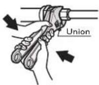
- When loosening a flare nut, always use two wrenches in combination. When connecting the piping, always use a spanner and torque wrench in combination to tighten the flare nut.
- When connecting a flare nut, coat the flare(inner and outer faces) with oil for R410A(PVE) and hand tighten the nut 3 to 4 turns as the initial tightening.
Opening shutoff valve
1 Remove the cap and turn the valve counter clockwise with the hexagon wrench.
2 Turn it until the shaft stops.
Do not apply excessive force to the shutoff valve. Doing so may break the valve body, as the valve is not a backseat type. Always use the special tool.
3 Make sure to tighten the cap securely.
Closing shutoff valve
1 Remove the cap and turn the valve clockwise with the hexagon wrench.
2 Securely tighten the valve until the shaft contacts the main body seal.
3 Make sure to tighten the cap securely.
* For the tightening torque, refer to the table on the below.
Tightening torque
| Shut off valve size (mm (inch)) | Tightening torque N·m (lbs·ft) (Turn clockwise to close) | ||||||
| Shaft (valve body) | Cap (Valve lid) | Service port | Flare nut | Gas line piping attached to unit | |||
| Closed Opened | Hexagonal wrench | ||||||
| ∅ 6.35 (1/4) | 6.0±0.6(4.4±0.4) | 5.0=0.0(3.7±0.4) | 4 mm(0.16 inch) | 17.6±2.0(13.0±1.5) | 12.7±2(9.4±1.5) | 16±2(12±1.5) | - |
| ∅ 9.52 (3/8) | 38±4(28±3.0) | ||||||
| ∅ 12.7 (1/2) | 10.0±1.0(7.4±0.7) | 20.0±2.0(14.8±1.5) | 55±6(41±4.4) | ||||
| ∅ 15.88 (5/8) | 12.0±1.2(8.9±0.9) | 5 mm(0.24 inch) | 25.0±2.5(18.4±1.8) | 75±7(55±5.1) | |||
| ∅ 19.05 (3/4) | 14.0±1.4(10.3±1.0) | 110±10(81.1±7.4) | |||||
| ∅ 22.2 (7/8) | 30.0±3.0(22.1±2.2) | 8 mm(0.31 inch) | - | ||||
| ∅ 25.4 (1) | 25±3(18.5±2.2) | ||||||
Insulation of shutoff valve
1 Use the heat insulation material for the refrigerant piping which has an excellent heat-resistance (over 120 °C [248 °F]).
2 Precautions in high humidity circumstance:
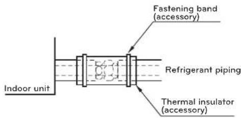
This air conditioner has been tested according to the "ISO Conditions with Mist" and confirmed that there is not any default. However, if it is operated for a long time in high humid atmosphere (dew point temperature: More than 23 °C [73.4 °F]), water drops are liable to fall. In this case, add heat insulation material according to the following procedure:
- Heat insulation material to be prepared: EPDM (Ethylene Propylene Diene Methylene)-over 120 °C [248 °F] the heat-resistance temperature.
- Add the insulation over 10 mm [0.39 inch] thickness at high humidity environment.
text_image
Fastening band (accessory) Refrigerant piping Thermal insulator (accessory) Indoor unitPlumbing materials and storage methods
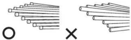
Pipe must be able to obtain the specified thickness and should be used with low impurities.
Also when handling storage, pipe must be careful to prevent a fracture, deformity and wound.
Should not be mixed with contaminations such as dust, moisture.
natural_image
Two groups of sticks: one with circles and another with crosses, both showing different lengths (no text or symbols)Refrigerant piping on three principles
| Drying | Cleanliness | Airtight | |
| Should be no moisture inside | No dust inside. | There is no refrigerant leakage | |
| Items | 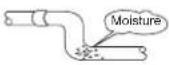 | 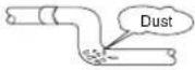 | 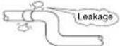 |
| Cause failure | - Significant hydrolysis of refrigerant oil- Degradation of refrigerant oil- Poor insula'tion of the compressor- Do not cold and warm- Clogging of EEV, Capillary | - Degradation of refrigerant oil- Poor insulation of the compressor- Do not cold and warm- Clogging of EEV, Capillary | - Gas shortages- Degradation of refrigerant oil- Poor insulation of the compressor- Do not cold and warm |
| Counter measure | - No moisture in the pipe- Until the connection is completed, the plumbing pipe entrance should be strictly controlled.- Stop plumbing at rainy day.- Pipe entrance should be taken side or bottom.- When removal burr after cutting pipe, pipe entrance should be taken down.- Pipe entrance should be fitted cap when pass through the walls. | - No dust in the pipe.- Until the connection is completed, the plumbing pipe entrance should be strictly controlled.- Pipe entrance should be taken side or bottom.- When removal burr after cutting pipe, pipe entrance should be taken down.- Pipe entrance should be fitted cap when pass through the walls. | - Airtightness test should be.- Brazing operations to comply with standards.- Flare to comply with standards.- Flange connections to comply with standards. |
Nitrogen substitution method
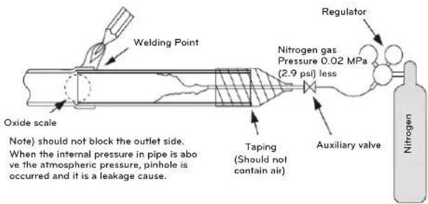
Welding, as when heating without nitrogen substitution a large amount of the oxide film is formed on the internal piping.
The oxide film is a caused by clogging EEV, Capillary, oil hole of accumulator and suction hole of oil pump in compressor.
It prevents normal operation of the compressor.
In order to avoid this problem, Welding should be done after replacing air by nitrogen gas.
When welding plumbing pipe, the work is required.
text_image
Welding Point Regulator Nitrogen gas Pressure 0.02 MPa (2.9 psi) less Oxide scale Taping (Should not contain air) Auxiliary valve Nitrogen Note) should not block the outlet side. When the internal pressure in pipe is above the atmospheric pressure, pinhole is occurred and it is a leakage cause.CAUTION
- Always use the nitrogen.(not use oxygen, carbon dioxide, and a Chevron gas): Please use the following nitrogen pressure 0.02 MPa (2.9 psi) Oxygen - Promotes oxidative degradation of refrigerant oil. Because it is flammable, it is strictly prohibited to use Carbon dioxide - Degrade the drying characteristics of gas Chevron Gas - Toxic gas occurs when exposed to direct flame.
• Always use a pressure reducing valve. - Please do not use commercially available antioxidant. The residual material seems to be the oxide scale is observed. In fact, due to the organic acids generated by oxidation of the alcohol contained in the anti-oxidants, ants nest corrosion occurs. (causes of organic acid alcohol + copper + water + temperature)
REFRIGERANT PIPING INSTALLATION
Precautions on Pipe connection / Valve operation
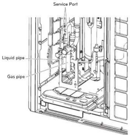
Pipe connection is done by connecting from the end of the pipe to the branching pipes, and the refrigerant pipe coming out of the outdoor unit is divided at the end to connect to each indoor unit. Flare connection for the indoor unit, and welding connection for the outdoor pipe and the branching parts.
- Use hexagonal wrench to open/close the valve.
text_image
Service Port Liquid pipe Gas pipe
WARNING
• Always careful not to leak the refrigerant during welding.
- The refrigerant generates poisonous gas harmful to human body if combusted.
- Do not perform welding in a closed space.
- Be sure to close the cap of the service port to prevent gas leakage after the work.

CAUTION
Please block the pipe knock outs of the front and side panels after installing the pipes.
(Animals or foreign objects may be brought in to damage wires.)
Connection of Outdoor units
When installing ODU series, refer below picture.
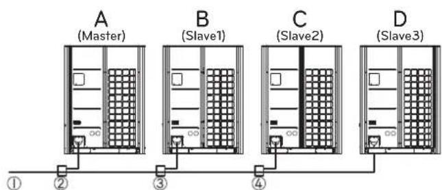
flowchart
graph TD
    A["Master"] -->|①| B["Slave1"]
    B -->|②| C["Slave2"]
    C -->|③| D["Slave3"]
    D -->|④| E["Slave2"]
    style A fill:#f9f,stroke:#333
    style B fill:#ccf,stroke:#333
    style C fill:#cfc,stroke:#333
    style D fill:#fcc,stroke:#333
A≥B≥C≥D
① IDU side connection pipe
② ODU to ODU connection pipe (1st branch)
③ ODU to ODU connection pipe (2st branch)
④ ODU to ODU connection pipe (3rd brach)
2, 3, 4 Outdoor Units
| Outdoor units | Model | Liquid Pipe | Gas Pipe | |
| 2 Unit | ARCNN21 | |||
| 3 Unit | ARCNN31 | |||
| 4 Unit | ARCNN41 | |||
For more information, refer accessory installation manual.
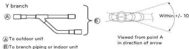
text_image
Y branch A To outdoor unit B To branch piping or indoor unit Viewed from point A in direction of arrow Within +/- 10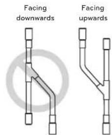
text_image
Facing downwards Facing upwards
CAUTION
Y-branches between the outside units must be installed horizontally.
Caution
1 Use the following materials for refrigerant piping.
- Material: Seamless phosphorous deoxidized copper pipe
- Wall thickness : Comply with the relevant local and national regulations for the designed pressure 3.8 MPa (551 psi). We recommend the following table as the minimum wall thickness.
| Outer diameter [mm/inch] | 6.35 (1/4) | 9.52 (3/8) | 12.7 (1/2) | 15.88 (5/8) | 19.05 (3/4) | 22.2 (7/8) | 25.4 (1) | 28.58 (1-1/8) | 31.8 (1-1/4) | 34.9 (1-3/8) | 38.1 (1-1/2) | 41.3 (1-5/8) | 44.45 (1-3/4) | 53.96 (2-1/8) |
| Minimum thickness [mm/inch] | 0.8 (0.03) | 0.8 (0.03) | 0.8 (0.03) | 0.99 (0.04) | 0.99 (0.04) | 0.99 (0.04) | 0.99 (0.04) | 0.99 (0.04) | 1.1 (0.04) | 1.21 (0.05) | 1.35 (0.05) | 1.43 (0.06) | 1.55 (0.06) | 2.1 (0.08) |
2 Commercially available piping often contains dust and other materials. Always blow it clean with a dry inert gas.
3 Use care to prevent dust, water or other contaminants from entering the piping during installation.
4 Reduce the number of bending portions as much as possible, and make bending radius as big as possible.
5 Always use the branch piping set shown below, which are sold separately.
| Y branch | Header | ||
| 4 branches | 7 branches | 10 branches | |
| ARBLB01621, ARBLB03321, ARBLB07121, ARBLB14521, ARBLB23220 | ARBL054 | ARBL057 | ARBL1010 |
| ARBL104 | ARBL107 | ARBL2010 | |
6 If the diameters of the branch piping of the designated refrigerant piping differs, use a pipe cutter to cut the connecting section and then use an adapter for connecting different diameters to connect the piping.
7 Always observe the restrictions on the refrigerant piping (such as rated length, difference in height, and piping diameter). Failure to do so can result in equipment failure or a decline in heating/cooling performance.
8 A second branch cannot be made after a header. (These are shown by ☑.)
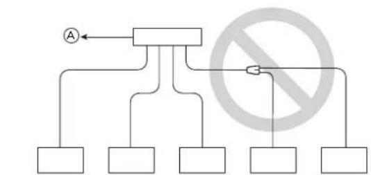
flowchart
graph TD
    A["Process Node"] --> B["Branch 1"]
    A --> C["Branch 2"]
    A --> D["Branch 3"]
    A --> E["Branch 4"]
    A --> F["Branch 5"]
    B --> G["Output"]
    C --> H["Output"]
    D --> I["Output"]
    E --> J["Output"]
    F --> K["Output"]
A To Outdoor Unit
B Sealed Piping
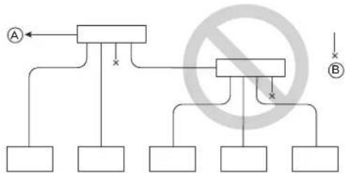
flowchart
graph TD
    A["Input"] --> B["Control Unit"]
    B --> C["Output 1"]
    B --> D["Output 2"]
    B --> E["Output 3"]
    B --> F["Output 4"]
    B --> G["Output 5"]
    H["No Prohibited Symbol"] --> I["Output 1"]
    H --> J["Output 2"]
    H --> K["Output 3"]
    H --> L["Output 4"]
    H --> M["Output 5"]
9 The Multi V will stop due to an abnormality like excessive or insufficient refrigerant. At such a time, always properly charge the unit. When servicing, always check the notes concerning both the piping length and the amount of additional refrigerant.
10 Never perform a pump down. This will not only damage the compressor but also deteriorate the performance.
11 Never use refrigerant to perform an air purge. Always evacuate air by using a vacuum pump.
12 Always insulate the piping properly. Insufficient insulation will result in a decline in heating/cooling performance, drip of condensate and other such problems.
13 When connecting the refrigerant piping, make sure the service valves of the Outdoor Unit is completely closed (the factory setting) and do not operate it until the refrigerant piping for the Outdoor and Indoor Units has been connected, a refrigerant leakage test has been performed and the evacuation process has been completed.
14 Always use a non-oxidizing brazing material for brazing the parts and do not use flux. If not, oxidized film can cause clogging or damage to the compressor unit and flux can harm the copper piping or refrigerant oil.
WARNING
When installing and moving the air conditioner to another site, be sure to make recharge refrigerant after perfect evacuation.
- If a different refrigerant or air is mixed with the original refrigerant, the refrigerant cycle may malfunction and the unit may be damaged.
- After selecting diameter of the refrigerant pipe to suit total capacity of the indoor unit connected after branching, use an appropriate branch pipe set according to the pipe diameter of the indoor unit and the installation pipe drawing.
PIPE CONNECTIONS BETWEEN INDOOR AND OUTDOOR UNIT
- Pipe connections can be done on the front side or on the side according to the installation environments.
- Be sure to let 0.2 kgf/cm² (2.8 psi) Nitrogen flow in the pipe when welding.
- If Nitrogen was not flown during welding, many oxidized membranes may form inside the pipe and disturb the normal operations of valves and condensers.
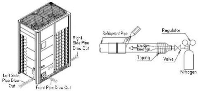
text_image
Left Side Pipe Draw Out Front Pipe Draw Out Right Side Pipe Draw Out Refrigerant Pipe Regulator Nitrogen Direction Taping Valve NitrogenPreparation Work
- Use Knock Outs of Base Pan of the outdoor unit for Left/Right or Bottom pipe drawing outs.
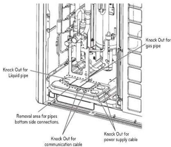
text_image
Knock Out for gas pipe Knock Out for Liquid pipe Removal area for pipes bottom side connections. Knock Out for communication cable Knock Out for power supply cableCAUTION
- Do not give damage to the pipe/base during the Knock Out work.
- Proceed to pipe work after removing burr after Knock Out work.
- Perform sleeve work to prevent damage to the wire when connecting wires using Knock Outs.
Remove leakage prevention cap
- Remove the leakage prevention cap attached to the outdoor unit service valve before pipe work.
-
Proceed the leakage prevention cap removal as follows:
-
Verify whether all the pipes are locked.
- Extract remaining refrigerant or air inside using the service port.
- Remove the leakage prevention cap
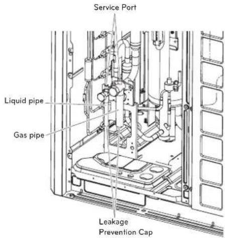
text_image
Service Port Liquid pipe Gas pipe Leakage Prevention CapPipe Drawing Out during Single / Series connection
Method of drawing out pipes on the front side
- Proceed with the pipe work as shown in the below figure for front side pipe drawing out.
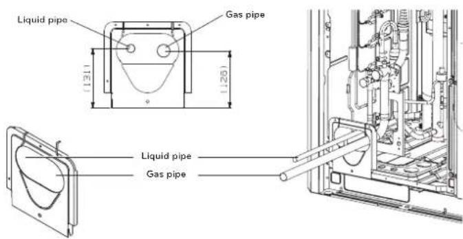
text_image
Liquid pipe Gas pipe Liquid pipe Gas pipeMethod of drawing out pipes on the bottom side
- Drawing out common pipe through side panel
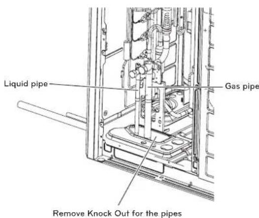
text_image
Liquid pipe Gas pipe Remove Knock Out for the pipesRefrigerant piping system
1 Outdoor Units
Y branch method
Ⓐ : Outdoor Unit
⑧ : 1st branch (Y branch)
©: Indoor Units
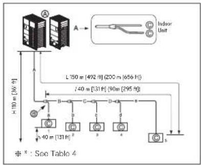
text_image
A A → Indoor Unit L10 m [36 ft] L 150 m [492 ft] (200 m) [656 ft] L40 m [131 ft] [90 m] [295 ft] B C D 40 m [131 ft] * : See Table 4Combination of Y branch/header Method
Ⓐ : Outdoor Unit
⑧ : 1st branch (Y branch)
©: Y branch
⑭: Indoor Unit
E: Header
⑤ : Sealed piping
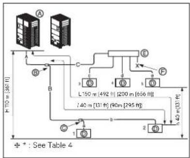
text_image
H 70 m [36 ft] A B C D E F L 150 m [492 ft] [200 m [656 ft]] L 40 m [131 ft] (90m [295 ft]) A 40 m [131 ft] + + : See Table 4Header Method
Ⓐ : Outdoor Unit
©: Indoor Units
⑭: Sealed piping
E: Header
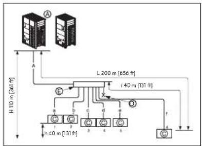
text_image
H10 m [361ft] L 200 m [656 ft] 140 m [131 ft] h 40 m [131ft]Series Outdoor Units (2 Units \~ 4 Units)
Y branch method
Ⓐ : Outdoor Unit
⑧: 1st branch (Y branch)
©: Indoor Units
⑤ : Connection branch pipe between Outdoor units: ARCNN41
⑤ : Connection branch pipe between Outdoor units : ARCNN31
G : Connection branch pipe between Outdoor units : ARCNN21
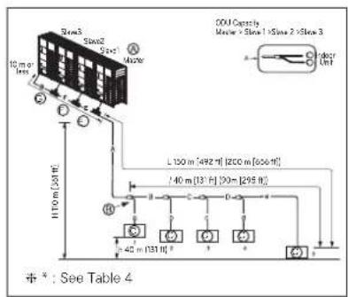
text_image
Master1 Master2 Master3 10 m or less 110 m (58 ft) L 100 m (492 ft) (200 m (606 ft)) 140 m (131 ft) (20 m (295 ft)) 42 m (131 ft) COU Capacity Master > Master 1 > Master 2 > Master 3 + * : See Table 4Combination of Y branch/ header Method
Ⓐ : Outdoor Unit
⑧: 1st branch(Y branch)
©: Y branch
⑭: Indoor Unit
⑤ : Connection branch pipe between Outdoor units : ARCNN41
⑤ : Connection branch pipe between Outdoor units : ARCNN31
⑥ : Connection branch pipe between Outdoor units : ARCNN21
⑧ : Header
① : Sealed piping
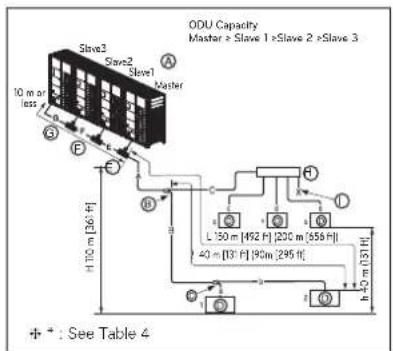
text_image
ODU Capacity Master ≥ Slave 1 > Slave 2 > Slave 3 Slave3 Slave2 Slave1 Master 10 m on less H 100 m [36 ft] L 150 m [492 ft] [200 m (556 ft)] 40 m [131 ft] [90m] [295 ft] + * : See Table 4Header Method
Ⓐ : Outdoor Unit
⑧ : Header
©: Indoor Units
⑭ : Sealed piping
⑤ : Connection branch pipe between Outdoor units : ARCNN41
⑤ : Connection branch pipe between Outdoor units : ARCNN31
G : Connection branch pipe between Outdoor units : ARCNN21
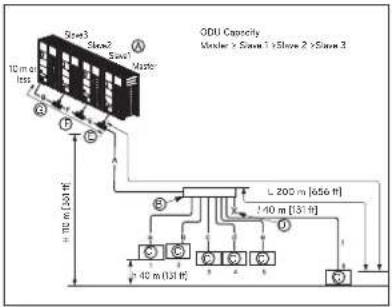
text_image
ODU Capacity Master > Slave 1 > Slave 2 > Slave 3 Size 3 Size 2 Size Master 10 m x 100 m (30 ft) L 200 m [656 ft] 140 m [131 ft] +40 m (131 ft)Pipe Connection Method between outdoor unit/indoor unit
flowchart
graph TD
    A["Master"] -->|L2| B["Indoor Unit"]
    C["Slave1"] -->|H1| D["F"]
    E["Slave2"] -->|G| D
    F["Slave3"] -->|L1| D
    B --> G["1st branch"]
    D --> G
    G --> H["Refrigerant pipe diameter from outdoor unit to first branch"]
    H --> I["40 m (131 ft)"]
    I --> J["h 40 m (131 ft)²"]
    J --> K["4"]
    K --> L["40 m (131 ft)³"]
    L --> M["4"]
    M --> N["40 m (131 ft)⁴"]
    N --> O["40 m (131 ft)⁵"]
    O --> P["40 m (131 ft)⁶"]
* See Table 2
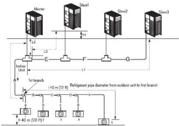
A: Refrigerant pipe diameter from outdoor unit to first branch
E: Refrigerant pipe diameter for outdoor unit capacity (Slave 1+ Slave 2+ Slave 3)
F : Refrigerant pipe diameter for outdoor unit capacity (Slave 2+ Slave 3)
G : Refrigerant pipe diameter for outdoor unit capacity(Slave 3)
! WARNING
- Branch pipe can not be used after header.
- It is recommended that difference in length of the pipes connected to the indoor units (a\~f) is minimized. Performance difference between indoor units may occur.
| Level Difference(Outdoor unit ↔ Outdoor unit) | 5 m [16.4 ft] |
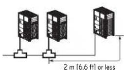
| Max length from first branch to each outdoor unit (L1, L2, L3) | Less than 10 m [32.8 ft](equivalent length of piping 13 m[42.7 ft]) |
(Table 1) Limit Pipe length
| Y branch Method | Combination of Y branch/header Method | Header Method | |||
| Max pipe length | Outdoor Unit ↔ Indoor Unit | Longest pipe length(L) | A+B+C+D+e ≤ 150 m [492 ft] (200 m [856 ft] : Conclonal application)* | A+B+b ≤ 150 m [492 ft] A+C+e ≤ 150 m [492 ft] (200 m [856 ft] : Conclonal application)* | A+f ≤ 200 m [658 ft] |
| Equivalent pipe length | 175 m [574 ft] (225 m [738 ft] : Conclonal application)* | 175 m [574 ft] (225 m [738 ft] : Conclonal application)* | 225 m [738 ft] | ||
| Total pipe length | 1000 m [3281 ft] 1000 m [3281 ft] | 1000 m [3281 ft] | |||
| Max difference in height | Outdoor Unit ↔ Indoor Unit | Difference in height(H) | 110 m [361 ft] 110 m | [361 ft] 110 m [361 ft] | |
| Indoor Unit ↔ Indoor Unit | Difference in height(h) | 40 m [131 ft] 40 m [131 ft] | 40 m [131 ft] | ||
| Longest pipe length after 1st branch | Pipe length(ℓ) | 40 m [131 ft] (90 m [295 ft] : Conclonal application)* | 40 m [131 ft] (90 m [295 ft] : Conclonal application)* | 40 m [131 ft] | |
* : See Table 4
! WARNING
Increased Pipe Diameter(table 2)
- When pipe length is 90 m [295 ft] or more from ODU to 1st branch
- When level difference is 50 m [164 ft] or more
(Table 2) Refrigerant pipe diameter from outdoor unit to first branch. (A)
| ODU capacity (hp) | Pipe diameter when pipe length is < 90 m (295 ft) (Standard) | Pipe diameter when pipe length is ≥ 90 m (295 ft) | Pipe diameter when height differential IODU × IDU s > 50 m (164 ft) | |||
| Liquid Pipe mm (inch) | Gas Pipe mm (inch) | Liquid Pipe mm (inch) | Gas Pipe mm (inch) | Liquid Pipe mm (inch) | Gas Pipe mm (inch) | |
| 8 | ∅ 9.52 (3/8) | ∅ 19.05 (3/4) ∅ | 12.7 (1/2) ∅ 22 | 2.2 (7/8) ∅ 12.7 | (1/2) Not increased | |
| 10 | ∅ 9.52 (3/8) | ∅ 22.2 (7/8) ∅ | 2.7 (1/2) | ∅ 28.58 (1-1/8) | ∅ 12.7 (1/2) | Not increased |
| 12~16 | ∅ 12.7 (1/2) | ∅ 26.58 (1-1/8) | ∅ 15.88 (5/8) | ∅ 34.9 (1-3/8) ∅ | 15.88 (5/8) | Not increased |
| 18~22 | ∅ 15.88 (5/8) | ∅ 28.58 (1-1/8) | ∅ 19.05 (3/4) | ∅ 34.9 (1-3/8) ∅ | 19.05 (3/4) | Not increased |
| 24 | ∅ 15.88 (5/8) | ∅ 34.9 (1-3/8) ∅ | 19.05 (3/4) ∅ | 41.3 (1-5/8) ∅ | 9.05 (3/4) | Not increased |
| 26~34 | ∅ 19.05 (3/4) | ∅ 34.9 (1-3/8) | ∅ 22.2 (7/8) | ∅ 41.3 (1-5/8) | ∅ 22.2 (7/8) | Not increased |
| 36~60 | ∅ 19.05 (3/4) | ∅ 41.3 (1-5/8) | ∅ 22.2 (7/8) | ∅ 44.5 (1-3/4) | ∅ 22.2 (7/8) | Not increased |
| 62~64 | ∅ 22.2 (7/8) | ∅ 44.5 (1-3/4) | ∅ 25.4 (1) | ∅ 53.98 (2-1/8) | ∅ 25.4 (1) | Not increased |
| 66~96 | ∅ 22.2 (7/8) | ∅ 53.98 (2-1/8) | ∅ 25.4 (1) | ∅ 53.98 (2-1/8) | ∅ 25.4 (1) | Not increased |
(Table 3) Refrigerant pipe diameter from first branch to last branch (B,C,D)
| Downward indoor unit total capacity [kW(Btu/h)] | Liquid pipe [mm(inch)] | Gas pipe [mm(inch)] |
| ≤ 5.6(19 100) | ∅ 6.35(1/4) | ∅ 12.7(1/2) |
| < 16.0 (54 600) | ∅ 9.52(3/8) | ∅ 15.88(5/8) |
| ≤ 22.4 (76 400) | ∅ 9.52(3/8) | ∅ 19.05(3/4) |
| < 33.6 (114 700) ∅ 9.52(3/8) | ∅ 22.2(7/8) | |
| < 50.4 (172 000) ∅ 12.7(1/2) | ∅ 28.58(1-1/8) | |
| < 67.2 (229 400) | ∅ 15.88(5/8) ∅ 28.58(1-1/8) | |
| < 72.8(248 500) | ∅ 15.88(5/8) | ∅ 34.9(1-3/8) |
| < 100.8(344 000) | ∅ 19.05(3/4) | ∅ 34.9(1-3/8) |
| < 173.6(592 500) | ∅ 19.05(3/4) | ∅ 41.3(1-5/8) |
| < 184.8(630 700) | ∅ 22.2(7/8) | ∅ 44.5(1-3/4) |
| ≤ 224.0(764 400) | ∅ 22.2(7/8) | ∅ 53.98(2-1/8) |
(Table 4) Conditional Application
- To satisfy below condition to make 40m 90m of pipe length after first branch.
| Condition | Example | ||
| 1 | Diameter of pipes between first branch and the last branch should be increased by one step, except pipe diameter B,C,D is same as Diameter A | 40 m [131 ft] < B+C+D+e90 m [295 ft] → B, C, D Change a diameter | ∅ 6.36(1/4) → ∅ 9.52(3/8), ∅ 9.52(3/8) → ∅ 12.7(1/2) ∅ 12.7(1/2) → ∅ 15.88(5/8), ∅ 15.88(5/8) → ∅ 19.05(3/4), ∅ 19.05(3/4) → ∅22.2(7/8), ∅ 22.2(7/8) → ∅ 25.4(1), ∅ 25.4(1) → ∅ 28.58(1-1/8), ∅ 28.58(1-1/8) → ∅ 31.8(1-1/4), ∅ 31.8(1-1/4) → ∅ 34.9(1-3/8), ∅ 34.9(1-3/8) → ∅ 38.1(1-1/2) |
| 2 | While calculating whole refrigerant pipe length, pipe B,C,D length should be calculated twice. | A+Bx2+Cx2+Dx2+a+b+c+d+e ≤ 1 000 m [3 281 ft] | 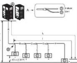 |
| 3 | Length of pipe from each indoor unit to the closest branch | a,b,c,d,e ≤ 40 m [131 ft] | |
| 4 | Length of pipe from outdoor unit to the farthest indoor unit 5 (A+B+C+D+ei) - [Length of pipe outdoor unit to the closest indoor unit 1 (A+a)] ≤ 40 m [131 ft] | (A+B+C+D+e)-(A+a) ≤ 40 m [131 ft] | |
WARNING
- In case of pipe diameter B connected after first branch is bigger than the main pipe diameter A, B should be of the same size with A.
Ex) In case indoor unit combination ratio 120 % is connected to 24 HP(67.2 kW) outdoor unit.
1) Outdoor unit main pipe diameter A : ∅ 34.9(1-3/8)(Gas pipe), ∅ 15.88(5/8)(liquid pipe)
2) Pipe diameter B after first branch according to 120 % indoor unit combination(80.6 kW): ∅ 34.9(1-3/8)(gas pipe), ∅ 19.05(3/4)(liquid pipe)
Therefore, pipe diameter B connected after first branch would be ∅ 34.9(1-3/8)(gas pipe) / ∅ 15.88(5/8)(liquid pipe) which is same with main pipe diameter.
Indoor Unit Connection
Indoor Unit connecting pipe from branch (a,b,c,d,e,f)
| Indoor Unit capacity [kW(Btu/h)] | Liquid pipe [mm(inch)] | Gas pipe [mm(inch)] |
| ≤ 5.6(19 100) | ∅ 6.35(1/4) ∅ 12.7(1/2) | |
| < 16.0(54 600) ∅ 9 | 52(3/8) ∅ 15.88(5/8) | |
| < 22.4(76 400) ∅ 9 | 52(3/8) ∅ 19.05(3/4) | |
| < 28.0(95 900) ∅ 9 | 52(3/8) ∅ 22.2(7/8) |
CAUTION
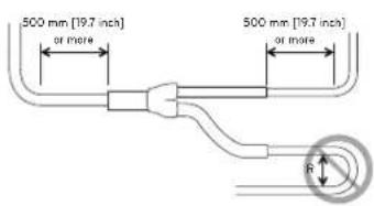
- Bending radius should be at least twice the diameter of the pipe.
- Bend pipe after 500 mm [19.7 inch] or more from branch (or header). Do not bend U type. It may affect performance or result in noise. If U type bending is required, the R should be more than 200 mm [7.9 inch]
text_image
500 mm [19.7 inch] or more 500 mm [19.7 inch] or more RPipe Connection Method/Precautions for Series connections between Outdoor units
- Separate Y branch joints are needed for series connections between outdoor units.
- Please refer to the below connection examples to install pipe connections between outdoor units.
Pipe connection between outdoor units (General Case)

text_image
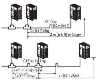
The maximum pipe length after the first branching between the outdoor units is 10 m [32.8 ft] or lessPipes between outdoor units are 2 m [6.6 ft] or less
Pipes between outdoor units are 2 m [6.6 ft] or longer
text_image
Oil Trap 2 m [6.6 ft] or less 2 m [6.6 ft] or longer Oil Trap Oil Trap 2 m [6.6 ft] or less 2 m [6.6 ft] or longer 2 m [6.6 ft] or longer- If the distance between the outdoor units becomes more than 2 m [6.6 ft], apply Oil Traps between the gas pipes.
- If the outdoor unit is located lower than the main pipe, apply Oil Trap.
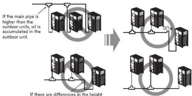
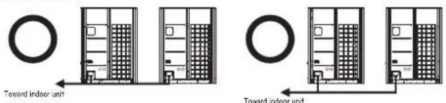
Examples of Wrong Pipe Connections
flowchart
graph TD
    A["Main Pipe"] --> B["Outdoor Units"]
    C["Oil"] --> D["Outdoor Units"]
    E["Difference"] --> F["Outdoor Units"]
    G["Difference"] --> H["Height"]
    style A fill:#f9f,stroke:#333
    style C fill:#f9f,stroke:#333
    style E fill:#f9f,stroke:#333
    style G fill:#f9f,stroke:#333
    style B fill:#ccf,stroke:#333
    style D fill:#ccf,stroke:#333
    style F fill:#ccf,stroke:#333
    style H fill:#ccf,stroke:#333
    note1["If the main pipe is higher than the outdoor units, oil is accumulated in the outdoor unit."]
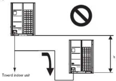
If there are differences in the height between the outdoor units, oil is accumulated in the lower outdoor unit.
(Example 1)
text_image
Toward indoor unit Toward indoor unit(Example 2)
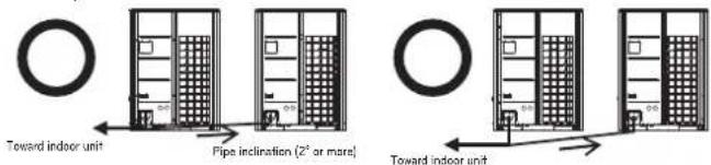
text_image
Toward indoor unit Pipe inclination (2° or more) Toward indoor unit(Example 3)
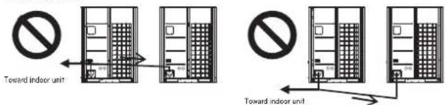
text_image
Toward indoor unit Toward indoor unit- Apply Oil Trap as shown below when the length of the pipe between the outdoor units is more than 2 m [6.6 ft]. Otherwise, the unit may not operate properly.
(Example 1)
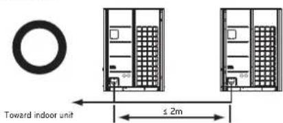
text_image
Toward indoor unit ≤ 2m(Example 2)
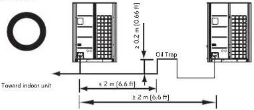
text_image
Toward indoor unit ≤ 2 m [6.6 ft] ≥ 2 m [6.6 ft] Oil Trap- When connecting the pipes between the outdoor units, the accumulation of oil in the slave outdoor unit should be avoided. Otherwise, the unit may not operate properly.
(Example 1)
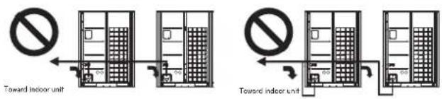
text_image
Toward Indoor unit Toward Indoor Unit(Example 2)
text_image
Toward indoor unit h(Example 3)
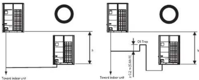
text_image
Toward indoor unit Oil Trapp ≥0.2 m (0.661) Toward indoor unit h hBranch pipe Fitting
Y branch

text_image
A ① To Outdoor Unit ② To Branch Piping or Indoor UnitCAUTION
Y-branches between the outside units must be installed horizontally.
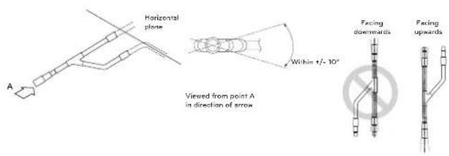
text_image
Horizontal plane A Viewed from point A in direction of arrow Within +/- 10° Facing downwards Facing upwards- There is no limitation on the joint mounting configuration.
- If the diameter of the refrigerant piping selected by the procedures described is different from the size of the joint, the connecting section should be cut with a pipe cutter.
- Branch pipe should be insulated with the insulator in each kit.
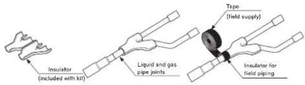
text_image
Insulator (included with kit) Liquid and gas pipe joints Tape (field supply) Insulator for field pipingHeader
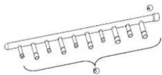
natural_image
Pure mechanical diagram of a lever system with multiple supports and a handle, no text or symbols present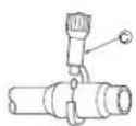
Ⓐ To Outdoor Unit
⑧ To Indoor Unit
- The indoor unit having larger capacity must be installed closer to Ⓐ than smaller one.
- If the diameter of the refrigerant piping selected by the procedures described is different from the size of the joint, the connecting section should be cut with a pipe cutter.
© Pipe cutter
- When the number of pipes to be connected is smaller than the number of header branches, install a cap to the unconnected branches.
- When the number of indoor units to be connected to the branch pipes is less than the number of branch pipes available for connection then cap pipes should be fitted to the surplus branches.
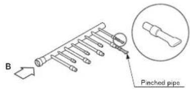
text_image
B Pinched pipe• Fit branch pipe lie in a horizontal plane.
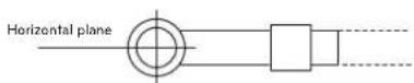
View from point B in the direction of the arrow
- Header should be insulated with the insulator in each kit.
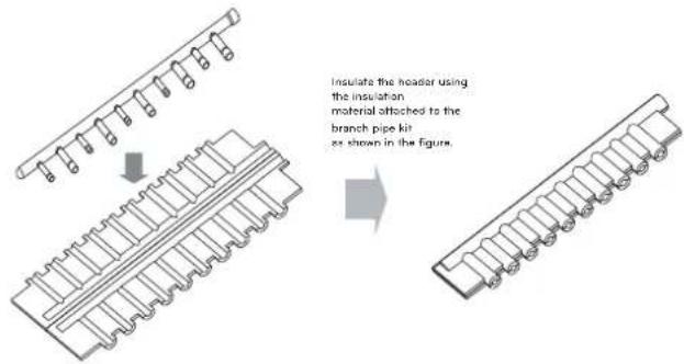
text_image
Insulate the header using the insulation material attached to the branch pipe kit as shown in the figure.- Joints between branch and pipe should be sealed with the tape included in each kit.
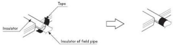
text_image
Tape Insulator Insulator of field pipe- Any cap pipe should be insulated using the insulator provided with each kit and then taped as described above.

text_image
Insulator for cap pipe Cap pipe TapeY branch pipe
[Unit:mm(inch)]
| Models | Gas pipe Liquid pipe | |
| ARBLN01621 | 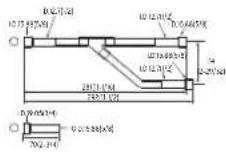 | 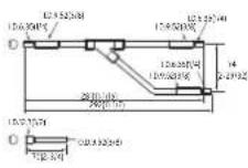 |
| ARBLN03321 | 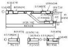 | 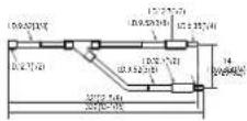 |
| ARBLN07121 | 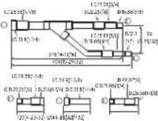 | 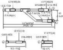 |
| ARBLN14521 | 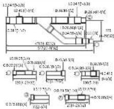 | 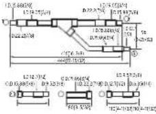 |
| ARBLN23220 | 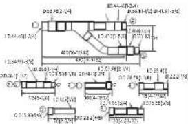 | 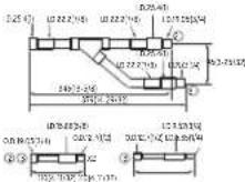 |
Header
[Unit:mm(inch)]
| Models | Gas pipe | Liquid pipe |
| 4 branch ARBL054 | 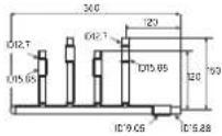 | 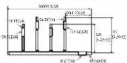 |
| 7 branch ARBL057 | 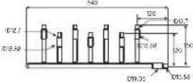 | 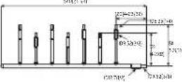 |
| 4 branch ARBL104 | 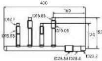 | 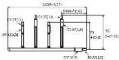 |
| 7 branch ARBL107 | 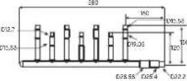 | 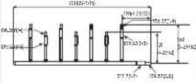 |
| 10 branch ARBL1010 | 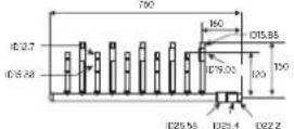 | 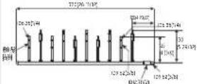 |
| 10 branch ARBL2010 | 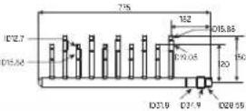 | 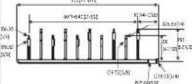 |
Distribution Method
Horizontal Distribution
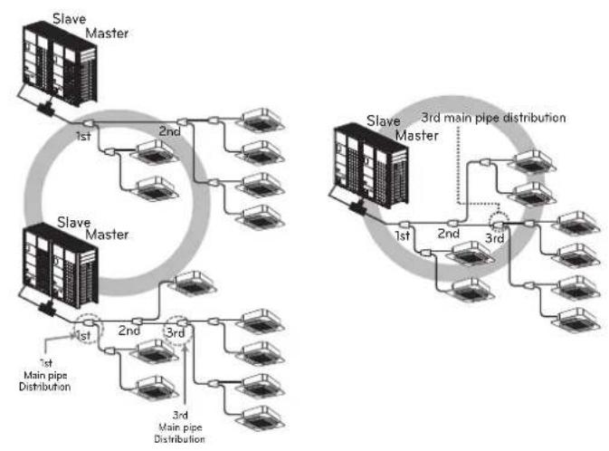
flowchart
graph TD
    subgraph_Master_Architecture["Slave Master"]
        A1["1st"] --> A2["2nd"]
        A2 --> A3["3rd"]
        A3 --> A4["1st"]
        A4 --> A5["2nd"]
        A5 --> A6["3rd"]
        A6 --> A7["1st"]
        A7 --> A8["2nd"]
        A8 --> A9["3rd"]
        A9 --> A10["1st"]
        A10 --> A11["2nd"]
        A11 --> A12["3rd"]
        A12 --> A13["1st"]
        A13 --> A14["2nd"]
        A14 --> A15["3rd"]
        A15 --> A16["1st"]
        A16 --> A17["2nd"]
        A17 --> A18["3rd"]
        A18 --> A19["1st"]
        A19 --> A20["2nd"]
        A20 --> A21["3rd"]
        A21 --> A22["1st"]
        A22 --> A23["2nd"]
        A23 --> A24["3rd"]
        A24 --> A25["1st"]
        A25 --> A26["2nd"]
        A26 --> A27["3rd"]
        A27 --> A28["1st"]
        A28 --> A29["2nd"]
        A29 --> A30["3rd"]
        A30 --> A31["1st"]
        A31 --> A32["2nd"]
        A32 --> A33["3rd"]
        A33 --> A34["1st"]
        A34 --> A35["2nd"]
        A35 --> A36["3rd"]
        A36 --> A37["1st"]
        A37 --> A38["2nd"]
        A38 --> A39["3rd"]
        A39 --> A40["1st"]
        A40 --> A41["2nd"]
        A41 --> A42["3rd"]
        A42 --> A43["1st"]
        A43 --> A44["2nd"]
        A44 --> A45["3rd"]
        A45 --> A46["1st"]
        A46 --> A47["2nd"]
        A47 --> A48["3rd"]
        A48 --> A49["1st"]
        A49 --> A50["2nd"]
        A50 --> A51["3rd"]
        A51 --> A52["1st"]
        A52 --> A53["2nd"]
        A53 --> A54["3rd"]
        A54 --> A55["1st"]
        A55 --> A56["2nd"]
        A56 --> A57["3rd"]
        A57 --> A58["1st"]
        A58 --> A59["2nd"]
        A59 --> A60["3rd"]
        A60 --> A61["1st"]
        A61 --> A62["2nd"]
        A62 --> A63["3rd"]
        A63 --> A64["1st"]
        A64 --> A65["2nd"]
        A65 --> A66["3rd"]
        A66 --> A67["1st"]
        A67 --> A68["2nd"]
        A68 --> A69["3rd"]
        A69 --> A70["1st"]
        A70 --> A71["2nd"]
        A71 --> A72["3rd"]
        A72 --> A73["1st"]
        A73 --> A74["2nd"]
        A74 --> A75["3rd"]
        A75 --> A76["1st"]
        A76 --> A77["2nd"]
        A77 --> A78["3rd"]
        A78 --> A79["1st"]
        A79 --> A80["2nd"]
        A80 --> A81["3rd"]
        A81 --> A82["1st"]
        A82 --> A83["2nd"]
        A83 --> A84["3rd"]
        A84 --> A85["1st"]
        A85 --> A86["2nd"]
        A86 --> A87["3rd"]
        A87 --> A88["1st"]
        A88 --> A89["2nd"]
        A89 --> A90["3rd"]
        A90 --> A91["1st"]
        A91 --> A92["2nd"]
        A92 --> A93["3rd"]
        A93 --> A94["1st"]
        A94 --> A95["2nd"]
        A95 --> A96["3rd"]
        A96 --> A97["1st"]
        A97 --> A98["2nd"]
        A98 --> A99["3rd"]
    end
Vertical Distribution
- Ensure that the branch pipes are attached vertically.
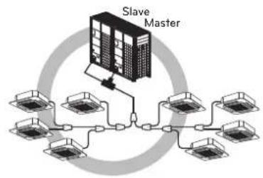
flowchart
graph TD
    A["Slave Master"] --> B["Server"]
    B --> C["Client 1"]
    B --> D["Client 2"]
    B --> E["Client 3"]
    B --> F["Client 4"]
    B --> G["Client 5"]
    B --> H["Client 6"]
    B --> I["Client 7"]
    B --> J["Client 8"]
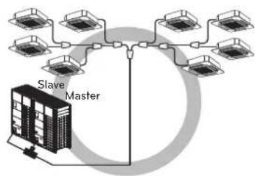
flowchart
graph TD
    A["Slave Master"] --> B["Central Hub"]
    B --> C["Database"]
    B --> D["Database"]
    B --> E["Database"]
    B --> F["Database"]
    B --> G["Database"]
    B --> H["Database"]
    B --> I["Database"]
    B --> J["Database"]
    B --> K["Database"]
    B --> L["Database"]
    B --> M["Database"]
    B --> N["Database"]
    B --> O["Database"]
    B --> P["Database"]
    B --> Q["Database"]
    B --> R["Database"]
    B --> S["Database"]
    B --> T["Database"]
    B --> U["Database"]
    B --> V["Database"]
    B --> W["Database"]
    B --> X["Database"]
    B --> Y["Database"]
    B --> Z["Database"]
The others
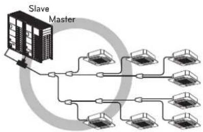
flowchart
graph TD
    A["Slave Master"] --> B["Server"]
    B --> C["Client Rack 1"]
    B --> D["Client Rack 2"]
    B --> E["Client Rack 3"]
    B --> F["Client Rack 4"]
    B --> G["Client Rack 5"]
    B --> H["Client Rack 6"]
    B --> I["Client Rack 7"]
    B --> J["Client Rack 8"]
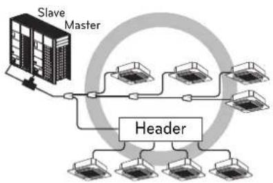
flowchart
graph TD
    A["Slave Master"] --> B["Server Rack"]
    B --> C["Header"]
    C --> D["Server Rack 1"]
    C --> E["Server Rack 2"]
    C --> F["Server Rack 3"]
    C --> G["Server Rack 4"]
    C --> H["Server Rack 5"]
Vacuum Mode
This function is used for creating vacuum in the system after compressor replacement, ODU parts replacement or IDU addition/replacement.
Vacuum mode setting method
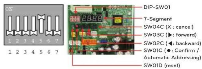
text_image
ON 1 2 3 4 5 6 7 1 2 3 4 5 6 7 DIP-SW01 7-Segment SW04C (X : cancel) SW03C (►: forward) SW02C (◄: backward) SW01C (●: Confirm / Automatic Addressing) SW01D (reset)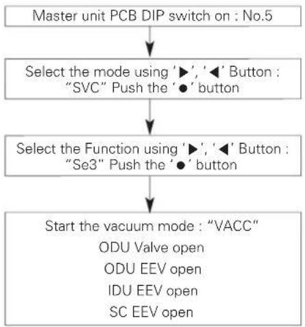
flowchart
graph TD
A["Master unit PCB DIP switch on : No.5"] --> B["Select the mode using '►', '◄' Button : "SVC" Push the '●' button"]
B --> C["Select the Function using '►', '◄' Button : "Se3" Push the '●' button"]
C --> D["Start the vacuum mode : "VACC"<br>ODU Valve open<br>ODU EEV open<br>IDU EEV open<br>SC EEV open"]
Vacuum mode off method
DIP switch off and push the reset button on Master unit PCB
CAUTION
ODU operation stops during vacuum mode. Compressor can't operate.
Leak Test and Vacuum drying
Leak test
Leak test should be made by pressurizing nitrogen gas to 3.8 MPa(38.7 kgf/cm²). If the pressure does not drop for 24 hours, the system passes the test. If the pressure drops, check where the nitrogen leaks. For the test method, refer to the following figure. (Make a test with the service valves closed. Be also sure to pressurize liquid pipe, gas pipe and high pressure gas pipe)
The test result can be judged good if the pressure has not be reduced after leaving for about one day after completion of nitrogen gas pressurization.
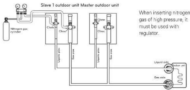
flowchart
graph TD
    A["Nitrogen gas cylinder"] --> B["Slave 1 outdoor unit"]
    B --> C["Master outdoor unit"]
    C --> D["Liquid side"]
    C --> E["Indoor unit"]
    C --> F["Gas side"]
    B --> G["Liquid pipe"]
    B --> H["Gas pipe"]
    style B fill:#f9f,stroke:#333
    note right of B: When inserting nitrogen gas of high pressure, it must be used with regulator.
WARNING
Use a vacuum pump or Inert(nitrogen) gas when doing leakage test or air purge. Do not compress air or Oxygen and do not use Flammable gases. Otherwise, it may cause fire or explosion.
- There is the risk of death, injury, fire or explosion.

NOTE
If the ambient temperature differs between the time when pressure is applied and when the pressure drop is checked, apply the following correction factor
There is a pressure change of approximately 0.01 Mpa(1.5 psi) for each 33.8 °F (1 °C) of temperature difference.
Correction= (Temp. at the time of pressurization - Temp. at the time of check) X 0.1
For example: Temperature at the time of pressurization
3.8 MPa(551psi) is 80.6 °F (27 °C)
24 hour later: 3.73 MPa(541 psi), 68 °F
(20 °C)
In this case the pressure drop of 0.07 MPa
(10 psi) is because of temperature drop
And hence there is no leakage in pipe
occurred.

CAUTION
To prevent the nitrogen from entering the refrigeration system in the liquid state, the top of the cylinder must be at higher position than the bottom when you pressurize the system.
Usually the cylinder is used in a vertical standing position.
Vacuum Drying
Vacuum drying should be made from the service port provided on the outdoor unit's service valve to the vacuum pump commonly used for liquid pipe, gas pipe and high/low pressure common pipe. (Make Vacuum from liquid pipe, gas pipe and high/low pressure common pipe with the service valve closed.)
* Never perform air purging using refrigerant.
• Vacuum drying: Use a vacuum pump that can evacuate to -100.7 kPa (-14.6 psi, 5 Torr, -755 mmHg).
- Evacuate the system from the liquid and gas pipes with a vacuum pump for over 2 hrs and bring the system to -100.7 kPa(-14.6 psi). After maintaining system under that condition for over 1 hr, confirm the vacuum gauge rises. The system may contain moisture or leak.
- Following should be executed if there is a possibility of moisture remaining inside the pipe.
(Rainwater may enter the pipe during work in the rainy season or over a long period of time)
After evacuating the system for 2 hrs, give pressure to the system to 0.05 MPa(7.3 psi) (vacuum break) with nitrogen gas and then evacuate it again with the vacuum pump for 1hr to -100.7 kPa(-14.6 psi)(vacuum drying). If the system cannot be evacuated to -100.7
kPa(-14.6 psi) within 2 hrs, repeat the steps of vacuum break and its drying. Finally, check if the vacuum gauge does not rise or not, after maintaining the system in vacuum for 1 hr.
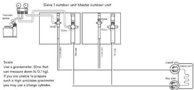
flowchart
graph TD
    A["Vacuum pump"] --> B["Slave 1 outdoor unit Master outdoor unit"]
    B --> C["Graviometer"]
    C --> D["Liquid side"]
    D --> E["Gas side"]
    style A fill:#f9f,stroke:#333
    style B fill:#ccf,stroke:#333
    style C fill:#cfc,stroke:#333
    style D fill:#fcc,stroke:#333
    style E fill:#cff,stroke:#333
! WARNING
Use a vacuum pump or Inert(nitrogen) gas when doing leakage test or air purge. Do not compress air or Oxygen and do not use Flammable gases. Otherwise, it may cause fire or explosion.
- There is the risk of death, injury, fire or explosion.
NOTE
Always add an appropriate amount of refrigerant. (For the refrigerant additional charge)
Too much or too little refrigerant will cause trouble.
To use the Vacuum Mode (If the Vacuum mode is set, all valves of Indoor units and Outdoor units will be opened.)
WARNING
When installing and moving the air conditioner to another site, recharge after perfect evacuation.
- If a different refrigerant or air is mixed with the original refrigerant, the refrigerant cycle may malfunction and the unit may be damaged.
Refrigerant charging
Heat Pump System Installation
Ⓐ Manifold Gauge
⑧ Low Pressure Side Handle
© High Pressure Side Handle
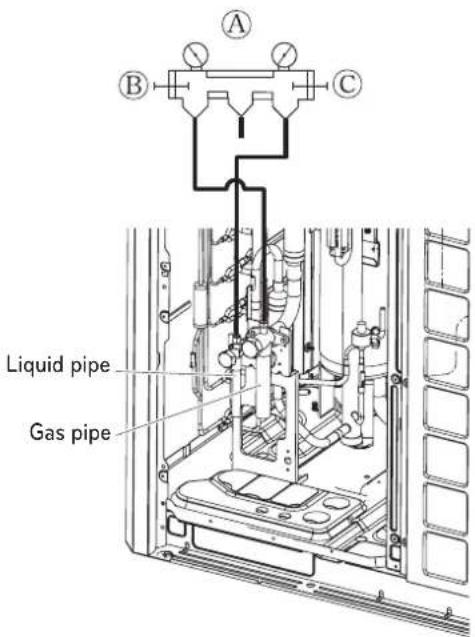
text_image
A B C Liquid pipe Gas pipeWARNING
- Pipe to be vacuumed: gas pipe, liquid pipe
- If the refrigerant amount is not exact, it may not operate properly.
- If additionally bottled refrigerant amount is over 10 %, condenser burst or insufficient indoor unit performance may be caused.
The amount of Refrigerant
The calculation of the additional charge should take into account the length of pipe and CF(correction Factor) value of indoor unit.
Additional charge(kg)
=
Total liquid pipe : ∅ 25.4 mm (1.0 inch)
× 0.480 kg/m (0.323 lbs/ft)
+
Total liquid pipe : ∅ 22.2 mm (7/8 inch)
× 0.354 kg/m [0.238 lbs/ft]
+
Total liquid pipe : ∅ 19.05 mm (3/4 inch)
× 0.266 kg/m [0.179 lbs/ft]
+
Total liquid pipe : ∅ 15.88 mm (5/8 inch)
× 0.173 kg/m (0.116 lbs/ft)
+
Total liquid pipe : ∅ 12.7 mm (1/2 inch)
× 0.118 kg/m (0.079 lbs/ft)
+
Total liquid pipe : ∅ 9.52 mm (3/8 inch)
× 0.061 kg/m (0.041 lbs/ft)
+
Total liquid pipe : ∅ 6.35 mm (1/4 inch)
× 0.022 kg/m (0.015 lbs/ft)
CF value of indoor unit
Amount refrigerant of Indoor units
Example) 4 Way Ceiling Cassette 14.5 kW -1ea, Ceiling concealed
Duct 7.3 kW-2 ea,
Wall Mounted 2.3 kW-4 ea
CF = [0.64 kg (1.411 lbs)×1 EA] + [0.26 kg (0.573 lbs)×2
EA] + [0.26 kg (0.529 lbs)×4 EA]
= 2.12 kg (4.67 lbs)
Attach the additional refrigerant table of IDU.

WARNING
• Regulation for refrigerant leakage
: the amount of refrigerant leakage should satisfy the following equation for human safety.
Total amount of refrigerant in the system
≤0.44 kg/m³
Volume of the room at which Indoor Unit of the least capacity is installed
(0.028 lbs/ft ^3 )
If the above equation can not be satisfied, then follow the following steps.
- Selection of air conditioning system: select one of the next
- Installation of effective opening part
- Reconfirmation of Outdoor Unit capacity and piping length
- Reduction of the amount of refrigerant
- Installation of 2 or more security device (alarm for gas leakage)
- Change Indoor Unit type
: installation position should be over 2 m (6.6 ft) from the floor (Wall mounted type → Cassette type)
- Adoption of ventilation system
: choose ordinary ventilation system or building ventilation system
- Limitation in piping work
: Prepare for earthquake and thermal stress
Thermal insulation of refrigerant piping
Be sure to give insulation work to refrigerant piping by covering liquid pipe and gas pipe separately with enough thickness heat-resistant polyethylene, so that no gap is observed in the joint between indoor unit and insulating material, and insulating materials themselves. When insulation work is insufficient, there is a possibility of condensation drip, etc. Pay special attention to insulation work to ceiling plenum.
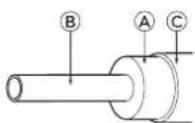
| Heat insulation material | Adhesive + Heat - resistant polyethylene foam + Adhesive tape | |
| Outer covering | Indoor V | nyl tape |
| Floor exposed | Water-proof hemp cloth + Bronze asphalt | |
| Outdoor | Water-proof hemp cloth + Zinc plate + Oily paint | |
Ⓐ Heat insulation material
⑧ Pipe
© Outer covering(Wind the connection part and cutting part of heat insulation material with a finishing tape.)
NOTE
When using polyethylene cover as covering material, asphalt roofing shall not be required.
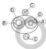
Bad example
- Do not insulate gas or low pressure pipe and liquid or high pressure pipe together.
text_image
A B F C D EⒶ Liquid pipe
⑧ Gas pipe
© Power lines
(d) Finishing tape
© Insulating material
f Communication lines
- Be sure to fully insulate connecting portion.
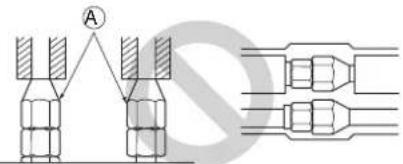
text_image
Technical diagram showing mechanical assembly with labeled component A and corresponding schematic viewⒶ These parts are not insulated.
Good example
text_image
D C B D A E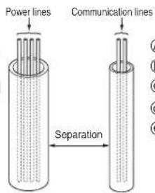
text_image
Power lines Communication lines SeparationⒶ Liquid pipe
⑧ Gas pipe
© Power lines
(d) Insulating material
© Communication lines
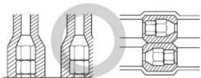
natural_image
Technical drawing of mechanical components with cross-sectional views (no text or symbols)Penetrations
Inner wall (concealed) Outer wall Outer wall (exposed)
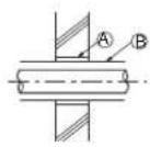
Floor (fireproofing)
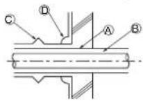
Penetrating portion on fire limit and boundary wall

Roof pipe shaft
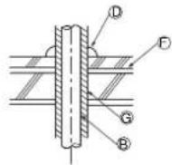
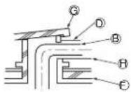
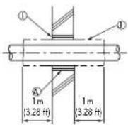
Ⓐ Sleeve
⑧ Heat insulating material
© Lagging
⑭ Caulking material
E Band
⑤ Waterproofing layer
© Sleeve with edge
⑧ Lagging material
① Mortar or other incombustible caulking
① Incombustible heat insulation material
When filling a gap with mortar, cover the penetration part with steel plate so that the insulation material will not be caved in. For this part, use incombustible materials for both insulation and covering. (Vinyl covering should not be used.)
ELECTRICAL WIRING
Caution
- Follow ordinance of your governmental organization for technical standard related to electrical equipment, wiring regulations and guidance of each electric power company.
WARNING
Be sure to have authorized electrical engineers do the electric work using special circuits in accordance with regulations and this installation manual.
If power supply circuit has a lack of capacity or electric work deficiency, it may cause an electric shock or fire.
- Install the Outdoor Unit communication cable away from the power source wiring so that it is not affected by electric noise from the power source. (Do not run it through the same conduit.)
- Be sure to provide designated grounding work to Outdoor Unit.
CAUTION
Be sure to correct the outdoor unit to earth. Do not connect ground wire to any gas pipe, liquid pipe, lightening rod or telephone earth line. If earth is incomplete, it may cause an electric shock.
- Give some allowance to wiring for electrical part box of Indoor and Outdoor Units, because the box is sometimes removed at the time of service work.
- Never connect the main power source to terminal block of communication cable. If connected, electrical parts will be burnt out.
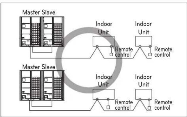
- Use the 2-core shielded wires for communication cable. (○ mark in the figure below) If communication cable of different systems are wired with the same multiplecore cable, the resultant poor transmitting and receiving will cause erroneous operations. (⊗ mark in the figure below)
- Only the communication cable specified should be connected to the terminal block for Outdoor Unit communication.
2-core shielded cables

flowchart
graph TD
    subgraph_Master_Slave_1["Master Slave 1"]
        A1["1 Unit"] --> B1["Slave 1"]
        A2["2 Unit"] --> B2["Slave 1"]
        A3["3 Unit"] --> B3["Slave 2"]
        A4["4 Unit"] --> B4["Slave 3"]
    end
    subgraph_Master_Slave_2["Master Slave 2 Slave 3"]
        B5["Master Slave 1"] --> C5["Slave 2"]
        B6["Master Slave 2 Slave 3"]
    end
    subgraph_Master_Slave_3["Master Slave 3"]
        C6["Master Slave 1"] --> D6["Slave 3"]
        C7["Master Slave 2 Slave 3"]
    end
    B1 --> E1["Indoor Unit"]
    B2 --> E2["Indoor Unit"]
    B3 --> E3["Indoor Unit"]
    B4 --> E4["Indoor Unit"]
    B5 --> F1["Remote control"]
    B6 --> F2["Remote control"]
    B7 --> F3["Remote control"]
    B8 --> F4["Remote control"]
    B9 --> F5["Remote control"]
flowchart
graph TD
    subgraph Master Slave
        A1["Desktop"] --> B1["Indoor Unit"]
        B1 --> C1["Remote control"]
    end
    subgraph Indoor Slave
        A2["Desktop"] --> B2["Indoor Unit"]
        B2 --> C2["Remote control"]
    end
    C1 --> D["Central Network"]
    C2 --> D
    D --> E["Indoor Unit"]
    D --> F["Indoor Unit"]
    style Master Slave fill:#f9f,stroke:#333
    style Indoor Slave fill:#bbf,stroke:#333
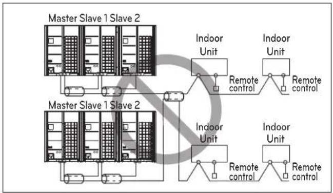
flowchart
graph TD
    subgraph Master Slave 1 Slave 2
        A["Server"] --> B["Indoor Unit"]
        C["Server"] --> D["Indoor Unit"]
        E["Server"] --> F["Indoor Unit"]
    end

    subgraph Master Slave 1 Slave 2
        G["Server"] --> H["Indoor Unit"]
        I["Server"] --> J["Indoor Unit"]
        K["Server"] --> L["Indoor Unit"]
    end

    B --> M["Remote control"]
    D --> N["Remote control"]
    F --> O["Remote control"]
    H --> P["Remote control"]
    J --> Q["Remote control"]
    L --> R["Remote control"]
    M --> S["Central Hub"]
    N --> S
    O --> S
    P --> S
    Q --> S
    R --> S
    S --> T["Output"]
    style Master Slave 1 Slave 2 fill:#f9f,stroke:#333
    style Master Slave 1 Slave 2 fill:#ccf,stroke:#333
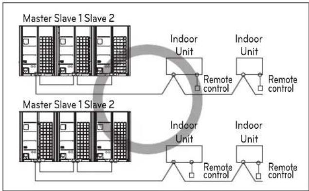
flowchart
graph TD
    subgraph Master Slave 1 Slave 2
        A["Server Block"] --> B["Indoor Unit"]
        B --> C["Remote control"]
    end
    subgraph Master Slave 1 Slave 2
        D["Server Block"] --> E["Indoor Unit"]
        E --> F["Remote control"]
    end
    B --> G["Indoor Unit"]
    F --> H["Remote control"]
    G --> I["Indoor Unit"]
    H --> J["Remote control"]
    style Master Slave 1 Slave 2 fill:#f9f,stroke:#333
    style Master Slave 1 Slave 2 fill:#ccf,stroke:#333
Multi-Core Cable
CAUTION
- Use the 2-core shielded wires for communication cables. Never use them together with power cables.
- The conductive shielding layer of cable should be grounded to the metal part of both units.
- Never use multi-core cable
- As this unit is equipped with an inverter, to install a phase leading capacitor not only will deteriorate power factor improvement effect, but also may cause capacitor abnormal heating. Therefore, never install a phase leading capacitor.
- Make sure that the power unbalance ratio is not greater than 2%. If it is greater the units lifespan will be reduced.
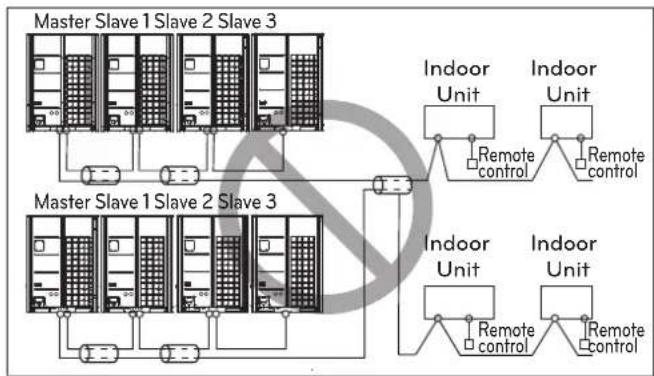
flowchart
graph TD
    subgraph Master Slave 1 Slave 2 Slave 3
        A["Server"] --> B["Node"]
        C["Server"] --> D["Node"]
        E["Server"] --> F["Node"]
        G["Server"] --> H["Node"]
    end

    subgraph Master Slave 1 Slave 2 Slave 3
        I["Server"] --> J["Node"]
        K["Server"] --> L["Node"]
        M["Server"] --> N["Node"]
        O["Server"] --> P["Node"]
    end

    subgraph Indoor Unit
        Q["Indoor Unit"] --> R["Remote control"]
        S["Indoor Unit"] --> T["Remote control"]
    end

    subgraph Indoor Unit
        U["Indoor Unit"] --> V["Remote control"]
        W["Indoor Unit"] --> X["Remote control"]
    end

    style Master Slave 1 Slave 2 Slave 3 fill:#f9f,stroke:#333
    style Indoor Unit fill:#ccf,stroke:#333
Precautions when laying power wiring
Use round pressure terminals for connections to the power terminal block.
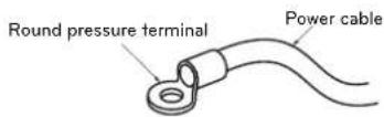
When none are available, follow the instructions below.
- Do not connect wiring of different thicknesses to the power terminal block. (Slack in the power wiring may cause abnormal heat.)
- When connecting cable which is the same thickness, do as shown in the figure below.
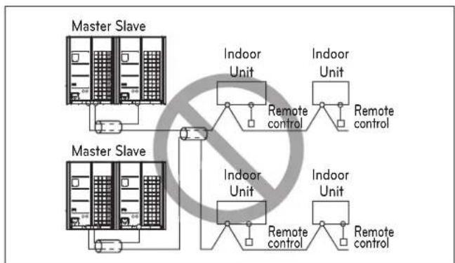
flowchart
graph TD
    subgraph Master Slave
        A1["Master Slave"] --> B1["Indoor Unit"]
        A2["Master Slave"] --> B2["Indoor Unit"]
        A3["Master Slave"] --> B3["Indoor Unit"]
    end
    subgraph Indoor Unit
        C1["Indoor Unit"] --> D1["Remote control"]
        C2["Indoor Unit"] --> D2["Remote control"]
    end
    B1 --> C1
    B2 --> C2
    B3 --> C3["Indoor Unit"]
    style Master Slave fill:#f9f,stroke:#333
    style Indoor Unit fill:#ccf,stroke:#333

natural_image
Three identical diagrams showing a vehicle inside a container with circular components, no text or symbols present.- For wiring, use the designated power cable and connect firmly, then secure to prevent outside pressure being exerted on the terminal block.
- Use an appropriate screwdriver for tightening the terminal screws. A screwdriver with a small head will strip the head and make proper tightening impossible.
- Over-tightening the terminal screws may break them.
Control box and connecting position of wiring
- Remove all of the screws at front panel and remove the panel by pulling it forward.
- Connect communication cable between main and sub outdoor unit through the terminal block.
- Connect communication cables between outdoor unit and indoor units through the terminal block.
- When the central control system is connected to the outdoor unit, a dedicated PCB must be connected between them.
- When connecting communication cable between outdoor unit and indoor units with shielded cable, connect the shield ground to the earth screw.
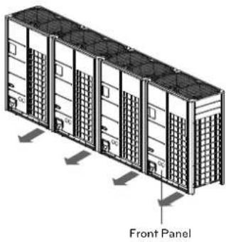
natural_image
Isometric diagram of a multi-unit server rack with front panel indicated (no text or symbols on the diagram itself)WARNING
The temperature sensor for outdoor air should not be exposed to direct sunlight.
- Provide an appropriate cover to intercept direct sunlight.
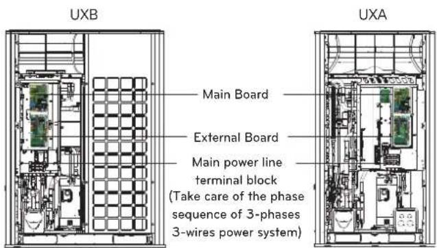
text_image
UXB Main Board External Board Main power line terminal block (Take care of the phase sequence of 3-phases 3-wires power system) UXACommunication and Power Cables
Communication cable
- Types : shielded wires or unshielded wires
- Cross section: 1.0 \~ 1.5 mm ^2 (1.55 × 10 ^-3 \~ 2.32 × 10 ^-3 in ^2 )
- Maximum allowable temperature: 60 °C (140 °F)
- Maximum allowable cable length: under 1 000 m (3 281 ft)
Remote control cable
- Types : 3-core cables
Central control cable
| Product type Cable | type Diameter | |
| ACP&AC Manager | 2-core wires (shielded) | 1.0 ~ 1.5 mm ^2 (1.55 × 10 ^-3 ~ 2.32 × 10 ^-3 in ^2 ) |
| AC Smart | 2-core wires (shielded) | 1.0 ~ 1.5 mm ^2 (1.55 × 10 ^-3 ~ 2.32 × 10 ^-3 in ^2 ) |
| Simple central controller | 4-core wires (shielded) | 1.0 ~ 1.5 mm ^2 (1.55 × 10 ^-3 ~ 2.32 × 10 ^-3 in ^2 ) |
| AC Ez | 4-core wires (shielded) | 1.0 ~ 1.5 mm ^2 (1.55 × 10 ^-3 ~ 2.32 × 10 ^-3 in ^2 ) |
CAUTION
In case of using the shielded wires, it should be grounded.
Separation of communication and power cables
- If communication and power cables are installed alongside each other then there is a strong likelihood of operational faults developing due to interference in the signal wiring caused by electrostatic and electromagnetic coupling. The tables below indicate our recommendation as to appropriate spacing of communication and power cables where these are to be run side by side
| Current capacity of power cable Spacing | |
| 100V or more | 10 A 300 mm (11-13/16 inch) |
| 50 A 500 mm (19-11/16 inch) | |
| 100 A 1 000 mm (39-3/8 inch) | |
| Exceed 100 A 1 500 mm (59-1/16 inch) | |
NOTE
- The figures are based on assumed length of parallel cabling up to 100 m [328 ft]. For length in excess of 100 m [328 ft] the figures will have to be recalculated in direct proportion to the additional length of cable involved.
- If the power supply waveform continues to exhibit some distortion the recommended spacing in the table should be increased.
- If the cable are laid inside conduits then the following point must also be taken into account when grouping various cable together for introduction into the conduits
- Power cable(including power supply to air conditioner) and communication cables must not be laid inside the same
- In the same way, when grouping the power wires and communication cables should not be bunched together.
CAUTION
If apparatus is not properly earthed then there is always a risk of electric shock, the grounding of the apparatus must be carried out by a qualified person.
Wiring of main power supply and equipment capacity
- Use a separate power supply for the Outdoor Unit and Indoor Unit.
- Bear in mind ambient conditions (ambient temperature, direct sunlight, rain water, etc.) when proceeding with the wiring and connections.
- The cable size is the minimum value for metal conduit wiring. The power cord size should be 1 rank thicker taking into account the line voltage drops. Make sure the power-supply voltage does not drop more than 10 %.
- Specific wiring requirements should adhere to the wiring regulations of the region.
- Power supply cords of parts of appliances for outdoor use should not be lighter than polychloroprene sheathed flexible cord.
- Don't install an individual switch or electrical outlet to disconnect each of indoor unit separately from the power supply.
| The thickness of Minimum wire (mm ^2 [ inch ^2 ]) | Leakage circuit breaker (4P ELCB) | |||
| Main power wire | Branch wire | Ground wire | ||
| 1 Unit | 2.5~16[3.875 × 10 ^3 ~2.48 × 10 ^2 ] | - | 2.5~4[3.875 × 10 ^3 ~6.2 × 10 ^3 ] | Below 20~60 A100 mA 0.1 sec |
| 2 Unit | 16~50[2.48 × 10 ^2 ~7.75 × 10 ^2 ] | - | 4~10[6.2 × 10 ^3 ~1.55 × 10 ^3 ] | Below 75~150 A100 mA 0.1 sec |
| 3 Unit | 50~95[7.75 × 10 ^2 ~1.4725 × 10 ^-1 ] | - | 10[1.55 × 10 ^2 ] | Below 150~200 A100 mA 0.1 sec |
| 4 Unit | 95~120[1.4725 × 10 ^-1 ~1.86 × 10 ^1 ] | - | 10~16[1.55 × 10 ^2 ~2.48 × 10 ^3 ] | Below 200~250 A100 mA 0.1 sec |
Ground wire
1 The power wire Between the master outdoor unit and slave 1 outdoor unit - minimum : 6 mm ^2 [9.3 × 10 ^-3 inch ^2 ]
2 The power wire Between the slave1 outdoor unit and slave2 outdoor unit - minimum : 4 mm² [6.2 × 10⁻³ inch²]
3 The power wire Between the slave2 outdoor unit and slave3 outdoor unit - minimum : 2.5 mm ^2 [3.875 × 10 ^-3 inch ^2 ]
* The above standard is CV wire standard.
* Please use the 3-phases 4-wires quadrupole Leakage circuit breaker of circuit breaker.

WARNING
- Follow ordinance of your governmental organization for technical standard related to electrical equipment, wiring regulations and guidance of each electric power company.
- Make sure to use specified cables for connections so that no external force is imparted to terminal connections. If connections are not fixed firmly, it may cause heating or fire.
- Make sure to use the appropriate type of overcurrent protection switch. Note that generated overcurrent may include some amount of direct current.

CAUTION
- Some installation site may require attachment of an earth leakage breaker. If no earth leakage breaker is installed, it may cause an electric shock.
- Do not use anything other than breaker and fuse with correct capacity. Using fuse and wire or copper wire with too large capacity may cause a malfunction of unit or fire.
Field Wiring
220-240V
Example Connection of Communication Cable
1 Outdoor Unit-3 ∅, 220-240 V
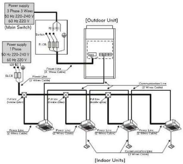
flowchart
graph TD
    A["Power supply 3 Phase 3 Wires\n50 Hz 220-240 V\n60 Hz 220 V\n(Main Switch)"] --> B["Switch"]
    B --> C["ELCB"]
    C --> D["Power Line (3 Wires Cable)"]
    D --> E["Outdoor Unit"]
    F["Power supply 1 Phase\n50 Hz 220-240 V\n60 Hz 220 V"] --> G["ELCB"]
    G --> H["Power Line (2 Wires Cable)"]
    H --> I["Pull box (inline option)"]
    I --> J["Power Line (2 Wires Cable)"]
    J --> K["Pull box (inline option)"]
    K --> L["Power Line (2 Wires Cable)"]
    L --> M["Pull box (inline option)"]
    M --> N["Power Line (2 Wires Cable)"]
    N --> O["Communication Line (2 Wires Cable)"]
    O --> P["Power Line (2 Wires Cable)"]
    P --> Q["Communication Line (3 Wires Cable)"]
    Q --> R["Power Line (2 Wires Cable)"]
    R --> S["Power Line (2 Wires Cable)"]
    S --> T["Power Line (2 Wires Cable)"]
    T --> U["Power Line (2 Wires Cable)"]
    U --> V["Power Line (2 Wires Cable)"]
    V --> W["Power Line (2 Wires Cable)"]
    W --> X["Power Line (2 Wires Cable)"]
    X --> Y["Power Line (2 Wires Cable)"]
    Y --> Z["Power Line (2 Wires Cable)"]
    Z --> AA["Power Line (2 Wires Cable)"]
    AA --> AB["Power Line (2 Wires Cable)"]
    AB --> AC["Power Line (2 Wires Cable)"]
    AC --> AD["Power Line (2 Wires Cable)"]
    AD --> AE["Power Line (2 Wires Cable)"]
    AE --> AF["Power Line (2 Wires Cable)"]
    AF --> AG["Power Line (2 Wires Cable)"]
    AG --> AH["Power Line (2 Wires Cable)"]
    AH --> AI["Power Line (2 Wires Cable)"]
    AI --> AJ["Power Line (2 Wires Cable)"]
    AJ --> AK["Power Line (2 Wires Cable)"]
    AK --> AL["Power Line (2 Wires Cable)"]
    AL --> AM["Power Line (2 Wires Cable)"]
    AM --> AN["Power Line (2 Wires Cable)"]
    AN --> AO["Power Line (2 Wires Cable)"]
    AO --> AP["Power Line (2 Wires Cable)"]
    AP --> AQ["Power Line (2 Wires Cable)"]
    AQ --> AR["Power Line (2 Wires Cable)"]
    AR --> AS["Power Line (2 Wires Cable)"]
    AS --> AT["Power Line (2 Wires Cable)"]
    AT --> AU["Power Line (2 Wires Cable)"]
    AU --> AV["Power Line (2 Wires Cable)"]
    AV --> AW["Power Line (2 Wires Cable)"]
    AW --> AX["Power Line (2 Wires Cable)"]
    AX --> AY["Power Line (2 Wires Cable)"]
    AY --> AZ["Power Line (2 Wires Cable)"]
    AZ --> BA["Power Line (2 Wires Cable)"]
    BA --> BB["Power Line (2 Wires Cable)"]
    BB --> BC["Power Line (2 Wires Cable)"]
    BC --> BD["Power Line (2 Wires Cable)"]
    BD --> BE["Power Line (2 Wires Cable)"]
    BE --> BF["Power Line (2 Wires Cable)"]
    BF --> BG["Power Line (2 Wires Cable)"]
    BG --> BH["Power Line (2 Wires Cable)"]
    BH --> BI["Power Line (2 Wires Cable)"]
    BI --> BJ["Power Line (2 Wires Cable)"]
    BJ --> BK["Power Line (2 Wires Cable)"]
    BK --> BL["Power Line (2 Wires Cable)"]
    BL --> BM["Power Line (2 Wires Cable)"]
    BM --> BN["Power Line (2 Wires Cable)"]
    BN --> BO["Power Line (2 Wires Cable)"]
    BO --> BP["Power Line (2 Wires Cable)"]
    BP --> BQ["Power Line (2 Wires Cable)"]
    BQ --> BR["Power Line (2 Wires Cable)"]
    BR --> BS["Power Line (2 Wires Cable)"]
    BS --> BT["Power Line (2 Wires Cable)"]
    BT --> BU["Power Line (2 Wires Cable)"]
    BU --> BV["Power Line (2 Wires Cable)"]
    BV --> BW["Power Line (2 Wires Cable)"]
    BW --> BX["Power Line (2 Wires Cable)"]
    BX --> BY["Power Line (2 Wires Cable)"]
    BY --> BZ["Power Line (2 Wires Cable)"]
    BZ --> CA["Power Line (2 Wires Cable)"]
    CA --> CB["Power Line (2 Wires Cable)"]
    CB --> CC["Power Line (2 Wires Cable)"]
    CC --> CD["Power Line (2 Wires Cable)"]
    CD --> CE["Power Line (2 Wires Cable)"]
    CE --> CF["Power Line (2 Wires Cable)"]
    CF --> CG["Power Line (2 Wires Cable)"]
    CG --> CH["Power Line (2 Wires Cable)"]
    CH --> CI["Power Line (2 Wires Cable)"]
    CI --> CJ["Power Line (2 Wires Cable)"]
    CJ --> CK["Power Line (2 Wires Cable)"]
    CK --> CL["Power Line (2 Wires Cable)"]
    CL --> CM["Power Line (2 Wires Cable)"]
    CM --> CN["Power Line (2 Wires Cable)"]
    CN --> CO["Power Line (2 Wires Cable)"]
    CO --> CP["Power Line (2 Wires Cable)"]
    CP --> CQ["Power Line (2 Wires Cable)"]
    CQ --> CR["Power Line (2 Wires Cable)"]
    CR --> CS["Power Line (2 Wires Cable)"]
    CS --> CT["Power Line (2 Wires Cable)"]
    CT --> CU["Power Line (2 Wires Cable)"]
    CU --> CV["Power Line (2 Wires Cable)"]
    CV --> CW["Power Line (2 Wires Cable)"]
    CW --> CX["Power Line (2 Wires Cable)"]
    CX --> CY["Power Line (2 Wires Cable)"]
    CY --> CZ["Power Line (2 Wires Cable)"]

WARNING
- Indoor unit ground lines are required for preventing electrical shock accident during current leakage, Communication disorder by noise effect and motor current leakage (without connection to pipe).
- Don't install an individual switch or electrical outlet to disconnect each of indoor unit separately from the power supply.
• Install the main switch that can interrupt all the power sources in an integrated manner because this system consists of the equipment utilizing the multiple power sources. - If there exists the possibility of reversed phase, lose phase, momentary blackout or the power goes on and off while the product is operating, attach a reversed phase protection circuit locally. Running the product in reversed phase may break the compressor and other parts.
- When using shielded wires, perform a single-point grounding only to the outdoor unit for grounding of communication wires.
Between Indoor and Master Outdoor unit
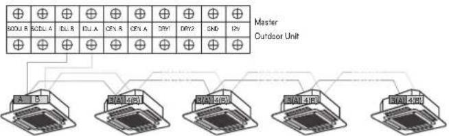
text_image
Master Curdoor Unit2 Outdoor Units-3 ∅, 220-240 V
When the power source is connected In series between the units.
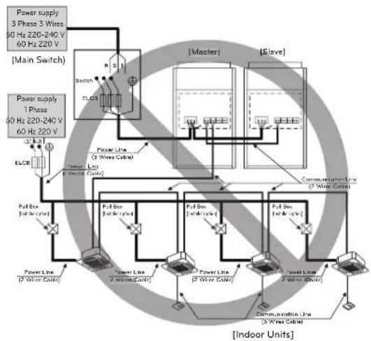
flowchart
graph TD
    A["Power supply 3 Phase 3 Wires\n50 Hz 220-240 V\n60 Hz 220 V\n(Main Switch)"] --> B["Switch"]
    B --> C["ELCE"]
    C --> D["Master"]
    D --> E["5 Grove"]
    D --> F["Communication Line (2 Wire Cable)"]
    D --> G["Full Box (1x1x1x1x1x1x1x1x1x1x1x1x1x1x1x1x1x1x1x1x1x1x1x1x1x1x1x1x1x1x1x1x1x1x1x1x1x1x1x1x1x1x1x1x1x1x1x1x1x1x1"] --> H["Power Line (2 Wire Cable)"]
    H --> I["Full Box (1x1x1x1x1x1x1x1x1x1x1x1x1x1x1x1x1x1x1x1x1x1x1x1x1x1x1x1x1x1x1x1x1x1x1x1x1x1"] --> J["Power Line (2 Wire Cable)"]
    J --> K["Full Box (2 Wire Cable)"]
    K --> L["Power Line (2 Wire Cable)"]
    L --> M["Full Box (2 Wire Cable)"]
    M --> N["Power Line (2 Wire Cable)"]
    N --> O["Power Line (2 Wire Cable)"]
    O --> P["Power Line (2 Wire Cable)"]
    P --> Q["Power Line (2 Wire Cable)"]
    Q --> R["Power Line (2 Wire Cable)"]
    R --> S["Power Line (2 Wire Cable)"]
    S --> T["Power Line (2 Wire Cable)"]
    T --> U["Power Line (2 Wire Cable)"]
    U --> V["Power Line (2 Wire Cable)"]
    V --> W["Power Line (2 Wire Cable)"]
    W --> X["Power Line (2 Wire Cable)"]
    X --> Y["Power Line (2 Wire Cable)"]
    Y --> Z["Power Line (2 Wire Cable)"]
    Z --> AA["Power Line (2 Wire Cable)"]
    AA --> AB["Power Line (2 Wire Cable)"]
    AB --> AC["Power Line (2 Wire Cable)"]
    AC --> AD["Power Line (2 Wire Cable)"]
    AD --> AE["Power Line (2 Wire Cable)"]
    AE --> AF["Power Line (2 Wire Cable)"]
    AF --> AG["Power Line (2 Wire Cable)"]
    AG --> AH["Power Line (2 Wire Cable)"]
    AH --> AI["Power Line (2 Wire Cable)"]
    AI --> AJ["Power Line (2 Wire Cable)"]
    AJ --> AK["Power Line (2 Wire Cable)"]
    AK --> AL["Power Line (2 Wire Cable)"]
    AL --> AM["Power Line (2 Wire Cable)"]
    AM --> AN["Power Line (2 Wire Cable)"]
    AN --> AO["Power Line (2 Wire Cable)"]
    AO --> AP["Power Line (2 Wire Cable)"]
    AP --> AQ["Power Line (2 Wire Cable)"]
    AQ --> AR["Power Line (2 Wire Cable)"]
    AR --> AS["Power Line (2 Wire Cable)"]
    AS --> AT["Power Line (2 Wire Cable)"]
    AT --> AU["Power Line (2 Wire Cable)"]
    AU --> AV["Power Line (2 Wire Cable)"]
    AV --> AW["Power Line (2 Wire Cable)"]
    AW --> AX["Power Line (2 Wire Cable)"]
    AX --> AY["Power Line (2 Wire Cable)"]
    AY --> AZ["Power Line (2 Wire Cable)"]
    AZ --> BA["Power Line (2 Wire Cable)"]
    BA --> BB["Power Line (2 Wire Cable)"]
    BB --> BC["Power Line (2 Wire Cable)"]
    BC --> BD["Power Line (2 Wire Cable)"]
    BD --> BE["Power Line (2 Wire Cable)"]
    BE --> BF["Power Line (2 Wire Cable)"]
    BF --> BG["Power Line (2 Wire Cable)"]
    BG --> BH["Power Line (2 Wire Cable)"]
    BH --> BI["Power Line (2 Wire Cable)"]
    BI --> BJ["Power Line (2 Wire Cable)"]
    BJ --> BK["Power Line (2 Wire Cable)"]
    BK --> BL["Power Line (2 Wire Cable)"]
    BL --> BM["Power Line (2 Wire Cable)"]
    BM --> BN["Power Line (2 Wire Cable)"]
    BN --> BO["Power Line (2 Wire Cable)"]
    BO --> BP["Power Line (2 Wire Cable)"]
    BP --> BQ["Power Line (2 Wire Cable)"]
    BQ --> BR["Power Line (2 Wire Cable)"]
    BR --> BS["Power Line (2 Wire Cable)"]
    BS --> BT["Power Line (2 Wire Cable)"]
    BT --> BU["Power Line (2 Wire Cable)"]
    BU --> BV["Power Line (2 Wire Cable)"]
    BV --> BW["Power Line (2 Wire Cable)"]
    BW --> BX["Power Line (2 Wire Cable)"]
    BX --> BY["Power Line (2 Wire Cable)"]
    BY --> BZ["Power Line (2 Wire Cable)"]
    BZ --> CA["Power Line (2 Wire Cable)"]
    CA --> CB["Power Line (2 Wire Cable)"]
    CB --> CC["Power Line (2 Wire Cable)"]
    CC --> CD["Power Line (2 Wire Cable)"]
    CD --> CE["Power Line (2 Wire Cable)"]
    CE --> CF["Power Line (2 Wire Cable)"]
    CF --> CG["Power Line (2 Wire Cable)"]
    CG --> CH["Power Line (2 Wire Cable)"]
    CH --> CI["Power Line (2 Wire Cable)"]
    CI --> CJ["Power Line (2 Wire Cable)"]
    CJ --> CK["Power Line (2 Wire Cable)"]
    CK --> CL["Power Line (2 Wire Cable)"]
    CL --> CM["Power Line (2 Wire Cable)"]
    CM --> CN["Power Line (2 Wire Cable)"]
    CN --> CO["Power Line (2 Wire Cable)"]
    CO --> CP["Power Line (2 Wire Cable)"]
    CP --> CQ["Power Line (2 Wire Cable)"]
    CQ --> CR["Power Line (2 Wire Cable)"]
    CR --> CS["Power Line (2 Wire Cable)"]
    CS --> CT["Power Line (2 Wire Cable)"]
    CT --> CU["Power Line (2 Wire Cable)"]
    CU --> CV["Power Line (2 Wire Cable)"]
    CV --> CW["Power Line (2 Wire Cable)"]
    CW --> CX["Power Line (2 Wire Cable)"]
    CX --> CY["Power Line (2 Wire Cable)"]
    CY --> CZ["Power Line (2 Wire Cable)"]
    CZ --> DA["Power Line (2 Wire Cable)"]
    DA --> DB["Power Line (2 Wire Cable)"]
    DB --> DC["Power Line (2 Wire Cable)"]
When the power source is supplied to Each outdoor unit individually.
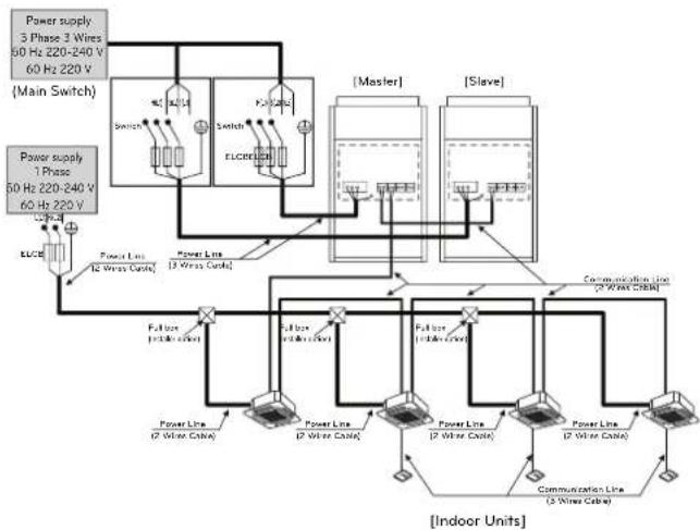
flowchart
graph TD
    A["Power supply 1 Phase 50 Hz 220-240 V 60 Hz 220 V (Main Switch)"] --> B["Switch"]
    A --> C["Switch"]
    A --> D["ELC"]
    E["Power supply 3 Phase 50 Hz 220-240 V 60 Hz 220 V"] --> F["ELC"]
    G["Power Line (2 Wires Cable)"] --> H["Power Line (2 Wires Cable)"]
    H --> I["Power Line (2 Wires Cable)"]
    I --> J["Power Line (2 Wires Cable)"]
    J --> K["Power Line (2 Wires Cable)"]
    K --> L["Power Line (2 Wires Cable)"]
    L --> M["Power Line (2 Wires Cable)"]
    M --> N["Power Line (2 Wires Cable)"]
    N --> O["Power Line (2 Wires Cable)"]
    O --> P["Power Line (2 Wires Cable)"]
    P --> Q["Power Line (2 Wires Cable)"]
    Q --> R["Power Line (2 Wires Cable)"]
    R --> S["Power Line (2 Wires Cable)"]
    S --> T["Power Line (2 Wires Cable)"]
    T --> U["Power Line (2 Wires Cable)"]
    U --> V["Power Line (2 Wires Cable)"]
    V --> W["Power Line (2 Wires Cable)"]
    W --> X["Power Line (2 Wires Cable)"]
    X --> Y["Power Line (2 Wires Cable)"]
    Y --> Z["Power Line (2 Wires Cable)"]
    Z --> AA["Power Line (2 Wires Cable)"]
    AA --> AB["Power Line (2 Wires Cable)"]
    AB --> AC["Power Line (2 Wires Cable)"]
    AC --> AD["Power Line (2 Wires Cable)"]
    AD --> AE["Power Line (2 Wires Cable)"]
    AE --> AF["Power Line (2 Wires Cable)"]
    AF --> AG["Power Line (2 Wires Cable)"]
    AG --> AH["Power Line (2 Wires Cable)"]
    AH --> AI["Power Line (2 Wires Cable)"]
    AI --> AJ["Power Line (2 Wires Cable)"]
    AJ --> AK["Power Line (2 Wires Cable)"]
    AK --> AL["Power Line (2 Wires Cable)"]
    AL --> AM["Power Line (2 Wires Cable)"]
    AM --> AN["Power Line (2 Wires Cable)"]
    AN --> AO["Power Line (2 Wires Cable)"]
    AO --> AP["Power Line (2 Wires Cable)"]
    AP --> AQ["Power Line (2 Wires Cable)"]
    AQ --> AR["Power Line (2 Wires Cable)"]
    AR --> AS["Power Line (2 Wires Cable)"]
    AS --> AT["Power Line (2 Wires Cable)"]
    AT --> AU["Power Line (2 Wires Cable)"]
    AU --> AV["Power Line (2 Wires Cable)"]
    AV --> AW["Power Line (2 Wires Cable)"]
    AW --> AX["Power Line (2 Wires Cable)"]
    AX --> AY["Power Line (2 Wires Cable)"]
    AY --> AZ["Power Line (2 Wires Cable)"]
    AZ --> BA["Power Line (2 Wires Cable)"]
    BA --> BB["Power Line (2 Wires Cable)"]
    BB --> BC["Power Line (2 Wires Cable)"]
    BC --> BD["Power Line (2 Wires Cable)"]
    BD --> BE["Power Line (2 Wires Cable)"]
    BE --> BF["Power Line (2 Wires Cable)"]
    BF --> BG["Power Line (2 Wires Cable)"]
    BG --> BH["Power Line (2 Wires Cable)"]
    BH --> BI["Power Line (2 Wires Cable)"]
    BI --> BJ["Power Line (2 Wires Cable)"]
    BJ --> BK["Power Line (2 Wires Cable)"]
    BK --> BL["Power Line (2 Wires Cable)"]
    BL --> BM["Power Line (2 Wires Cable)"]
    BM --> BN["Power Line (2 Wires Cable)"]
    BN --> BO["Power Line (2 Wires Cable)"]
    BO --> BP["Power Line (2 Wires Cable)"]
    BP --> BQ["Power Line (2 Wires Cable)"]
    BQ --> BR["Power Line (2 Wires Cable)"]
    BR --> BS["Power Line (2 Wires Cable)"]
    BS --> BT["Power Line (2 Wires Cable)"]
    BT --> BU["Power Line (2 Wires Cable)"]
    BU --> BV["Power Line (2 Wires Cable)"]
    BV --> BW["Power Line (2 Wires Cable)"]
    BW --> BX["Power Line (2 Wires Cable)"]
    BX --> BY["Power Line (2 Wires Cable)"]
    BY --> BZ["Power Line (2 Wires Cable)"]
    BZ --> CA["Power Line (2 Wires Cable)"]
    CA --> CB["Power Line (2 Wires Cable)"]
    CB --> CC["Power Line (2 Wires Cable)"]
    CC --> CD["Power Line (2 Wires Cable)"]
    CD --> CE["Power Line (2 Wires Cable)"]
    CE --> CF["Power Line (2 Wires Cable)"]
    CF --> CG["Power Line (2 Wires Cable)"]
    CG --> CH["Power Line (2 Wires Cable)"]
    CH --> CI["Power Line (2 Wires Cable)"]
    CI --> CJ["Power Line (2 Wires Cable)"]
    CJ --> CK["Power Line (2 Wires Cable)"]
    CK --> CL["Power Line (2 Wires Cable)"]
    CL --> CM["Power Line (2 Wires Cable)"]
    CM --> CN["Power Line (2 Wires Cable)"]
    CN --> CO["Power Line (2 Wires Cable)"]
    CO --> CP["Power Line (2 Wires Cable)"]
    CP --> CQ["Power Line (2 Wires Cable)"]
    CQ --> CR["Power Line (2 Wires Cable)"]
    CR --> CS["Power Line (2 Wires Cable)"]
    CS --> CT["Power Line (2 Wires Cable)"]
    CT --> CU["Power Line (2 Wires Cable)"]
    CU --> CV["Power Line (2 Wires Cable)"]
    CV --> CW["Power Line (2 Wires Cable)"]
    CW --> CX["Power Line (2 Wires Cable)"]
    CX --> CY["Power Line (2 Wires Cable)"]
    CY --> CZ["Power Line (2 Wires Cable)"]
    CZ --> DA["Power Line (2 Wires Cable)"]
    DA --> DB["Power Line (2 Wires Cable)"]
    DB --> DC["Power Line (2 Wires Cable)"]
    DC --> DD["Power Line (2 Wires Cable)"]
    DD --> DE["Power Line (2 Wires Cable)"]
    DE --> DF["Power Line (2 Wires Cable)"]
    DF --> DG["Power Line (2 Wires Cable)"]
    DG --> DH["Power Line (2 Wires Cable)"]
    DH --> DI["Power Line (2 Wires Cable)"]
    DI --> DJ["Power Line (2 Wires Cable)"]
    DJ --> DK["Power Line (2 Wires Cable)"]
    DK --> DL["Power Line (2 Wires Cable)"]
    DL --> DV["Power Line (2 Wires Cable)"]
    DV --> DW["Power Line (2 Wires Cable)"]
    DW --> DX["Power Line (2 Wires Cable)"]
    DX --> DY["Power Line (2 Wires Cable)"]

NOTE
- Field wiring diagram is to be used as a guideline only. Wiring should comply with applicable local and national codes
- ELCB must have function to prevent electrical short and over current at the same time.
- Use copper wires only.
- Unit must be grounded in compliance with the applicable local and national codes.
- ELCB and fuse/breaker must install to the power line

WARNING
- Indoor unit ground lines are required for preventing electrical shock accident during current leakage, Communication disorder by noise effect and motor current leakage (without connection to pipe).
- Don't install an individual switch or electrical outlet to disconnect each of indoor unit separately from the power supply.
- Install the main switch that can interrupt all the power sources in an integrated manner because this system consists of the equipment utilizing the multiple power sources.
- If there exists the possibility of reversed phase, lose phase, momentary blackout or the power goes on and off while the product is operating, attach a reversed phase protection circuit locally. Running the product in reversed phase may break the compressor and other parts.
Between Indoor and Master Outdoor unit
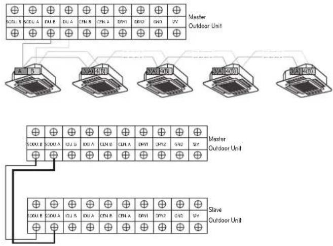
text_image
Master Outdoor Unit A 5 300U B 300U A 10U B 10U A 20N B 20N A 30V1 30V2 GND 12V Master Outdoor Unit 300U B 300U A 10U B 10U A 20N B 20N A 30V1 30V2 GND 12V Slave Outdoor Unit- It is not the point to make ground connection.
- Make sure that terminal number of master and slave outdoor units are matched.(A-A,B-B)
3 Outdoor Units-3 ∅, 220-240 V
When the power source is connected In series between the units.
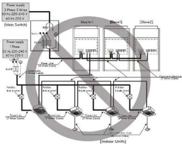
flowchart
graph TD
    A["Power supply 3 Phase 3 Wires 50 Hz 220-240 V 60 Hz 220 V (Main Switch)"] --> B["Switch"]
    C["Power supply 1 Phase 50 Hz 220-240 V 60 Hz 220 V"] --> B
    B --> D["FLCD"]
    D --> E["Master1"]
    D --> F["Slave1"]
    D --> G["Sleeve2"]
    E --> H["Power Line 13 Wire Cable"]
    F --> I["Power Line 21 Wire Cable"]
    G --> J["Power Line 12 Wire Cable"]
    H --> K["Pull Bit (Indoor Units)"]
    I --> L["Pull Bit (Indoor Units)"]
    J --> M["Pull Bit (Indoor Units)"]
    K --> N["Pull Bit (Indoor Units)"]
    L --> O["Pull Bit (Indoor Units)"]
    M --> P["Pull Bit (Indoor Units)"]
    N --> Q["Pull Bit (Indoor Units)"]
    O --> R["Pull Bit (Indoor Units)"]
    P --> S["Pull Bit (Indoor Units)"]
    Q --> T["Pull Bit (Indoor Units)"]
    R --> U["Pull Bit (Indoor Units)"]
    S --> V["Pull Bit (Indoor Units)"]
    T --> W["Pull Bit (Indoor Units)"]
    U --> X["Pull Bit (Indoor Units)"]
    V --> Y["Pull Bit (Indoor Units)"]
    W --> Z["Pull Bit (Indoor Units)"]
    X --> AA["Pull Bit (Indoor Units)"]
    Y --> AB["Pull Bit (Indoor Units)"]
    Z --> AC["Pull Bit (Indoor Units)"]
    AA --> AD["Pull Bit (Indoor Units)"]
    AB --> AE["Pull Bit (Indoor Units)"]
    AC --> AF["Pull Bit (Indoor Units)"]
    AD --> AG["Pull Bit (Indoor Units)"]
    AE --> AH["Pull Bit (Indoor Units)"]
    AF --> AI["Pull Bit (Indoor Units)"]
    AG --> AJ["Pull Bit (Indoor Units)"]
    AH --> AK["Pull Bit (Indoor Units)"]
    AI --> AL["Pull Bit (Indoor Units)"]
    AJ --> AM["Pull Bit (Indoor Units)"]
    AK --> AN["Pull Bit (Indoor Units)"]
    AL --> AO["Pull Bit (Indoor Units)"]
    AM --> AP["Pull Bit (Indoor Units)"]
    AN --> AQ["Pull Bit (Indoor Units)"]
    AO --> AR["Pull Bit (Indoor Units)"]
    AP --> AS["Pull Bit (Indoor Units)"]
    AQ --> AT["Pull Bit (Indoor Units)"]
    AR --> AU["Pull Bit (Indoor Units)"]
    AS --> AV["Pull Bit (Indoor Units)"]
    AT --> AW["Pull Bit (Indoor Units)"]
    AU --> AX["Pull Bit (Indoor Units)"]
    AV --> AY["Pull Bit (Indoor Units)"]
    AW --> AZ["Pull Bit (Indoor Units)"]
    AX --> BA["Pull Bit (Indoor Units)"]
    AY --> BB["Pull Bit (Indoor Units)"]
    AZ --> BC["Pull Bit (Indoor Units)"]
    BA --> BD["Pull Bit (Indoor Units)"]
    BB --> BE["Pull Bit (Indoor Units)"]
    BC --> BF["Pull Bit (Indoor Units)"]
    BE --> BG["Pull Bit (Indoor Units)"]
    BF --> BH["Pull Bit (Indoor Units)"]
    BG --> BI["Pull Bit (Indoor Units)"]
    BH --> BJ["Pull Bit (Indoor Units)"]
    BI --> BK["Pull Bit (Indoor Units)"]
    BJ --> BL["Pull Bit (Indoor Units)"]
    BK --> BM["Pull Bit (Indoor Units)"]
    BL --> BN["Pull Bit (Indoor Units)"]
    BM --> BO["Pull Bit (Indoor Units)"]
    BN --> BP["Pull Bit (Indoor Units)"]
    BO --> BQ["Pull Bit (Indoor Units)"]
When the power source is supplied to Each outdoor unit individually.
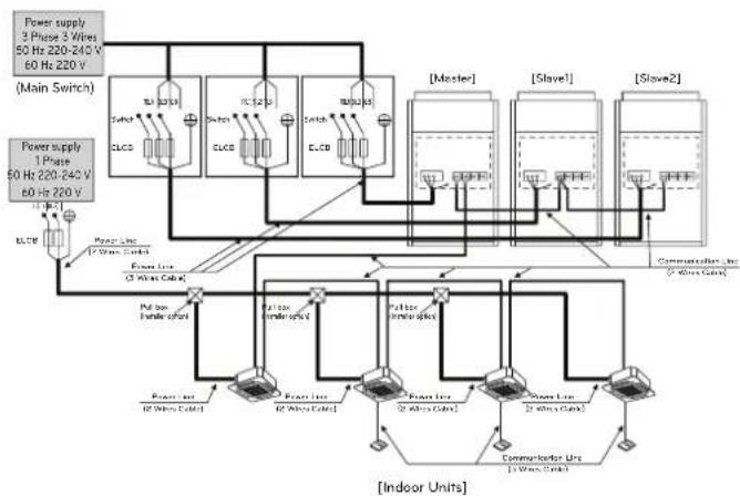
flowchart
graph TD
    A["Power supply 3 Phase 3 Wires 50 Hz 220-240 V 60 Hz 220 V (Main Switch)"] --> B["Switch"]
    A --> C["Switch"]
    A --> D["Switch"]
    A --> E["Switch"]
    F["Power supply 1 Phase 50 Hz 220-240 V 60 Hz 220 V (I-P1)"] --> G["BLTC"]
    G --> H["Power Line"]
    H --> I["Event Line"]
    I --> J["Pull box Handle short"]
    J --> K["Power Line"]
    J --> L["Pull box Handle long"]
    L --> M["Power Line"]
    L --> N["Pull box Handle short"]
    N --> O["Power Line"]
    N --> P["Pull box Handle long"]
    P --> Q["Power Line"]
    P --> R["Pull box Handle short"]
    R --> S["Power Line"]
    R --> T["Pull box Handle long"]
    T --> U["Power Line"]
    T --> V["Pull box Handle short"]
    V --> W["Power Line"]
    V --> X["Pull box Handle long"]
    X --> Y["Power Line"]
    X --> Z["Pull box Handle short"]
    Z --> AA["Power Line"]
    Z --> AB["Pull box Handle long"]
    AB --> AC["Power Line"]
    AB --> AD["Pull box Handle short"]
    AD --> AE["Power Line"]
    AD --> AF["Pull box Handle long"]
    AF --> AG["Power Line"]
    AF --> AH["Pull box Handle short"]
    AH --> AI["Power Line"]
    AH --> AJ["Pull box Handle long"]
    AJ --> AK["Power Line"]
    AJ --> AL["Pull box Handle short"]
    AL --> AM["Power Line"]
    AL --> AN["Pull box Handle long"]
    AN --> AO["Power Line"]
    AN --> AP["Pull box Handle short"]
    AP --> AQ["Power Line"]
    AP --> AR["Pull box Handle long"]
    AR --> AS["Power Line"]
    AR --> AT["Pull box Handle short"]
    AT --> AU["Power Line"]
    AT --> AV["Pull box Handle long"]
    AV --> AW["Power Line"]
    AV --> AX["Pull box Handle short"]
    AX --> AY["Power Line"]
    AX --> AZ["Pull box Handle long"]
    AZ --> BA["Power Line"]
    AZ --> BB["Pull box Handle short"]
    BB --> BC["Power Line"]
    BB --> BD["Pull box Handle long"]
    BD --> BE["Power Line"]
    BE --> BF["Pull box Handle short"]
    BF --> BG["Power Line"]
    BF --> BH["Pull box Handle long"]
    BH --> BI["Power Line"]
    BH --> BJ["Pull box Handle short"]
    BJ --> BK["Power Line"]
    BK --> BL["Pull box Handle long"]
    BL --> BM["Power Line"]
    BL --> BN["Pull box Handle short"]
    BN --> BO["Power Line"]
    BN --> BP["Pull box Handle long"]
    BP --> BQ["Power Line"]
    BP --> BR["Pull box Handle short"]
NOTE
- Field wiring diagram is to be used as a guideline only. Wiring should comply with applicable local and national codes
- ELCB must have function to prevent electrical short and over current at the same time.
- Use copper wires only.
- Unit must be grounded in compliance with the applicable local and national codes.
- ELCB and fuse/breaker must install to the power line
WARNING
- Indoor unit ground lines are required for preventing electrical shock accident during current leakage, communication disorder by noise effect and motor current leakage (without connection to pipe).
- Don't install an individual switch or electrical outlet to disconnect each of indoor unit separately from the power supply.
• Install the main switch that can interrupt all the power sources in an integrated manner because this system consists of the equipment utilizing the multiple power sources. - If there exists the possibility of reversed phase, lose phase, momentary blackout or the power goes on and off while the product is operating, attach a reversed phase protection circuit locally. Running the product in reversed phase may break the compressor and other parts.
Between Indoor and Master Outdoor unit

text_image
Master Outdoor Unit A 3 B(A)4(B)(A)4(B)3(A)4(B)(A)4(B) Master Outdoor Unit SODU B SODU A DUS IDU A CEN B CDN A DRY DRY SDN EY Slave1 Outdoor Unit SODU B SODU A DUS IDU A CEN B CDN A DRY DRY SDN EY Slave2 Outdoor Unit- It is not the point to make ground connection.
- Make sure that terminal number of master and slave outdoor units are matched.(A-A,B-B)
460V
Example Connection of Communication Cable
1 Outdoor Unit-3 ∅, 460 V
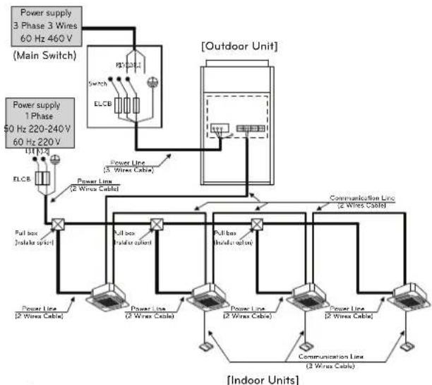
flowchart
graph TD
    A["Power supply 3 Phase 3 Wires 60 Hz 460 V (Main Switch)"] --> B["ELCB"]
    C["Power supply 1 Phase 50 Hz 220-240V 60 Hz 220 V"] --> D["ELCB"]
    B --> E["Power Line (2 Wires Cable)"]
    D --> F["Power Line (2 Wires Cable)"]
    E --> G["Pull box (Indicate slot)"]
    F --> H["Pull box (Indicate slot)"]
    G --> I["Power Line (2 Wires Cable)"]
    H --> J["Power Line (2 Wires Cable)"]
    I --> K["Power Line (2 Wires Cable)"]
    J --> L["Power Line (2 Wires Cable)"]
    K --> M["Communication Line (2 Wires Cable)"]
    L --> N["Communication Line (2 Wires Cable)"]
    M --> O["[Indoor Units"]]
    N --> P["[Indoor Units"]]
    style A fill:#f9f,stroke:#333
    style C fill:#f9f,stroke:#333
    style E fill:#ccf,stroke:#333
    style G fill:#cfc,stroke:#333
    style H fill:#cfc,stroke:#333
    style I fill:#fcc,stroke:#333
    style J fill:#fcc,stroke:#333
    style K fill:#fcc,stroke:#333
    style L fill:#fcc,stroke:#333
    style M fill:#fcc,stroke:#333
    style N fill:#fcc,stroke:#333
    style O fill:#fcc,stroke:#333
WARNING
- Indoor unit ground lines are required for preventing electrical shock accident during current leakage, Communication disorder by noise effect and motor current leakage (without connection to pipe).
- Don't install an individual switch or electrical outlet to disconnect each of indoor unit separately from the power supply.
- Install the main switch that can interrupt all the power sources in an integrated manner because this system consists of the equipment utilizing the multiple power sources.
- If there exists the possibility of reversed phase, lose phase, momentary blackout or the power goes on and off while the product is operating, attach a reversed phase protection circuit locally. Running the product in reversed phase may break the compressor and other parts.
Between Indoor and Master Outdoor unit
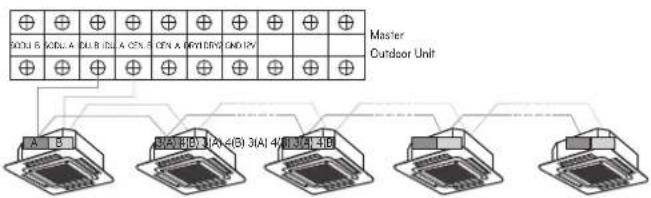
text_image
Master Outdoor Unit A 5 B 10 C 10 D 10 E 10 F 10 G 10 H 10 I 10 J 10 K 10 L 10 M 10 N 10 O 10 P 10 Q 10 R 10 S 10 T 10 U 10 V 10 W 10 X 10 Y 10 Z 102 Outdoor Units-3 ∅, 460 V
When the power source is connected In series between the units.
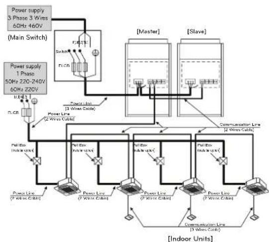
flowchart
graph TD
    A["Power supply 3 Phase 3 Wires 50Hz 460V (Main Switch)"] --> B["Switch"]
    B --> C["Power Line (2 Wires Cable)"]
    C --> D["Full Box (Indoor Units)"]
    D --> E["Power Line (2 Wires Cable)"]
    E --> F["Full Box (Subway)"]
    F --> G["Power Line (2 Wires Cable)"]
    G --> H["Full Box (Subway)"]
    H --> I["Power Line (2 Wires Cable)"]
    I --> J["Power Line (2 Wires Cable)"]
    J --> K["Power Line (Indoor Units)"]
    K --> L["Power Line (2 Wires Cable)"]
    L --> M["Full Box (Subway)"]
    M --> N["Power Line (2 Wires Cable)"]
    N --> O["Full Box (Subway)"]
    O --> P["Power Line (2 Wires Cable)"]
    P --> Q["Power Line (Indoor Units)"]
    Q --> R["Power Line (2 Wires Cable)"]
    R --> S["Power Line (Indoor Units)"]
    S --> T["Power Line (2 Wires Cable)"]
    T --> U["Power Line (Indoor Units)"]
    U --> V["Power Line (2 Wires Cable)"]
    V --> W["Power Line (Indoor Units)"]
    W --> X["Power Line (2 Wires Cable)"]
    X --> Y["Power Line (Indoor Units)"]
    Y --> Z["Power Line (2 Wires Cable)"]
    Z --> AA["Power Line (Indoor Units)"]
    AA --> AB["Power Line (2 Wires Cable)"]
    AB --> AC["Power Line (Indoor Units)"]
    AC --> AD["Power Line (2 Wires Cable)"]
    AD --> AE["Power Line (Indoor Units)"]
    AE --> AF["Power Line (2 Wires Cable)"]
    AF --> AG["Power Line (Indoor Units)"]
    AG --> AH["Power Line (2 Wires Cable)"]
    AH --> AI["Power Line (Indoor Units)"]
    AI --> AJ["Power Line (2 Wires Cable)"]
    AJ --> AK["Power Line (Indoor Units)"]
    AK --> AL["Power Line (2 Wires Cable)"]
    AL --> AM["Power Line (Indoor Units)"]
    AM --> AN["Power Line (2 Wires Cable)"]
    AN --> AO["Power Line (Indoor Units)"]
    AO --> AP["Power Line (2 Wires Cable)"]
    AP --> AQ["Power Line (Indoor Units)"]
    AQ --> AR["Power Line (2 Wires Cable)"]
    AR --> AS["Power Line (Indoor Units)"]
    AS --> AT["Power Line (2 Wires Cable)"]
    AT --> AU["Power Line (Indoor Units)"]
    AU --> AV["Power Line (2 Wires Cable)"]
    AV --> AW["Power Line (Indoor Units)"]
    AW --> AX["Power Line (2 Wires Cable)"]
    AX --> AY["Power Line (Indoor Units)"]
    AY --> AZ["Power Line (2 Wires Cable)"]
    AZ --> BA["Power Line (Indoor Units)"]
    BA --> BB["Power Line (2 Wires Cable)"]
    BB --> BC["Power Line (Indoor Units)"]
    BC --> BD["Power Line (2 Wires Cable)"]
    BD --> BE["Power Line (Indoor Units)"]
    BE --> BF["Power Line (2 Wires Cable)"]
    BF --> BG["Power Line (Indoor Units)"]
    BG --> BH["Power Line (2 Wires Cable)"]
    BH --> BI["Power Line (Indoor Units)"]
    BI --> BJ["Power Line (2 Wires Cable)"]
    BJ --> BK["Power Line (Indoor Units)"]
    BK --> BL["Power Line (2 Wires Cable)"]
    BL --> BM["Power Line (Indoor Units)"]
    BM --> BN["Power Line (2 Wires Cable)"]
    BN --> BO["Power Line (Indoor Units)"]
    BO --> BP["Power Line (2 Wires Cable)"]
    BP --> BQ["Power Line (Indoor Units)"]
    BQ --> BR["Power Line (2 Wires Cable)"]
    BR --> BS["Power Line (Indoor Units)"]
    BS --> BT["Power Line (2 Wires Cable)"]
    BT --> BU["Power Line (Indoor Units)"]
    BU --> BV["Power Line (2 Wires Cable)"]
    BV --> BW["Power Line (Indoor Units)"]
    BW --> BX["Power Line (2 Wires Cable)"]
    BX --> BY["Power Line (Indoor Units)"]
    BY --> BZ["Power Line (2 Wires Cable)"]
    BZ --> CA["Power Line (Indoor Units)"]
    CA --> CB["Power Line (2 Wires Cable)"]
    CB --> CC["Power Line (Indoor Units)"]
    CC --> CD["Power Line (2 Wires Cable)"]
    CD --> CE["Power Line (Indoor Units)"]
    CE --> CF["Power Line (2 Wires Cable)"]
    CF --> CG["Power Line (Indoor Units)"]
    CG --> CH["Power Line (2 Wires Cable)"]
    CH --> CI["Power Line (Indoor Units)"]
    CI --> CJ["Power Line (2 Wires Cable)"]
    CJ --> CK["Power Line (Indoor Units)"]

    subgraph Power Supply
        direction TB
        direction LR
        direction SB
        direction TB
        direction SB
        direction SB
        direction SB
        direction SB
        direction SB
        direction SB
        direction SB
        direction SB
        direction SB
        direction SB
        direction SB
        direction SB
        direction SB
        direction SB
        direction SB
        direction SB
        direction SB
        direction SB
        direction SB
        direction SB
        direction SB
        direction SB
        direction SB
        direction SB
        direction SB
        direction TB
        direction TB
        direction TB
        direction TB
        direction TB
        direction TB
        direction TB
        direction TB
        direction TB
        direction TB
        direction TB
        direction TB
        direction TB
        direction TB
        direction TB
        direction TB
        direction TB
        direction TB
        direction TB
        direction TB
        direction TB
        direction TB
        direction TB
        direction TB
        direction TB
        direction TC
        direction TC
        direction TC
        direction TC
        direction TC
        direction TC
        direction TC
        direction TC
        direction TC
        direction TC
        direction TC
        direction TC
        direction TC
        direction TC
        direction TC
        direction TC
        direction TC
        direction TC
        direction TC
        direction TC
        direction TC
        direction TC
        direction TC
        direction TC
        direction TC
        direction SC
        direction SC
        direction SC
        direction SC
        direction SC
        direction SC
        direction SC
        direction SC
        direction SC
        direction SC
        direction SC
        direction SC
        direction SC
        direction SC
        direction SC
        direction SC
        direction SC
        direction SC
        direction SC
        direction SC
        direction SC
        direction SC
        direction SC
        direction SC
        direction SC
        direction TC
        direction TC
        direction TC
        direction TC
        direction TC
        direction TC
        direction TC
        direction TC
        direction TC
        direction TC
        direction TC
        direction TC
        direction TC
        direction TC
        direction TC
        direction TC
        direction TC
        direction TC
        direction TC
        direction TC
        direction TC
        direction TC
When the power source is supplied to Each outdoor unit individually.
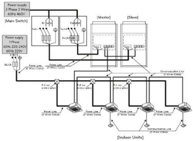
flowchart
graph TD
    A["Power supply 3 Phase 3 Wires 60Hz 460V (Main Switch)"] --> B["Switch"]
    A --> C["Switch"]
    A --> D["Switch"]
    A --> E["Power Line (12 Wires Cable)"]
    A --> F["Power Line (13 Wires Cable)"]
    G["Power supply 1 Phase 50Hz 220-240V 60Hz 220V"] --> H["LLC8"]
    H --> I["Power Line (12 Wires Cable)"]
    J["Power Line (12 Wires Cable)"] --> K["Power Line (12 Wires Cable)"]
    L["Power Line (12 Wires Cable)"] --> M["Power Line (12 Wires Cable)"]
    N["Power Line (12 Wires Cable)"] --> O["Power Line (12 Wires Cable)"]
    P["Power Line (12 Wires Cable)"] --> Q["Power Line (12 Wires Cable)"]
    R["Power Line (12 Wires Cable)"] --> S["Power Line (12 Wires Cable)"]
    T["Power Line (12 Wires Cable)"] --> U["Power Line (12 Wires Cable)"]
    V["Power Line (12 Wires Cable)"] --> W["Power Line (12 Wires Cable)"]
    X["Power Line (12 Wires Cable)"] --> Y["Power Line (12 Wires Cable)"]
    Z["Power Line (12 Wires Cable)"] --> AA["Power Line (12 Wires Cable)"]
    AB["Power Line (12 Wires Cable)"] --> AC["Power Line (12 Wires Cable)"]
    AD["Power Line (12 Wires Cable)"] --> AE["Power Line (12 Wires Cable)"]
    AF["Power Line (12 Wires Cable)"] --> AG["Power Line (12 Wires Cable)"]
    AH["Power Line (12 Wires Cable)"] --> AI["Power Line (12 Wires Cable)"]
    AJ["Power Line (12 Wires Cable)"] --> AK["Power Line (12 Wires Cable)"]
    AL["Power Line (12 Wires Cable)"] --> AM["Power Line (12 Wires Cable)"]
    AN["Power Line (12 Wires Cable)"] --> AO["Power Line (12 Wires Cable)"]
    AP["Power Line (12 Wires Cable)"] --> AQ["Power Line (12 Wires Cable)"]
    AR["Power Line (12 Wires Cable)"] --> AS["Power Line (12 Wires Cable)"]
    AT["Power Line (12 Wires Cable)"] --> AU["Power Line (12 Wires Cable)"]
    AV["Power Line (12 Wires Cable)"] --> AW["Power Line (12 Wires Cable)"]
    AX["Power Line (12 Wires Cable)"] --> AY["Power Line (12 Wires Cable)"]
    AZ["Power Line (12 Wires Cable)"] --> BA["Power Line (12 Wires Cable)"]
    BB["Power Line (12 Wires Cable)"] --> BC["Power Line (12 Wires Cable)"]
    BD["Power Line (12 Wires Cable)"] --> BE["Power Line (12 Wires Cable)"]
    BF["Power Line (12 Wires Cable)"] --> BG["Power Line (12 Wires Cable)"]
    BH["Power Line (12 Wires Cable)"] --> BI["Power Line (12 Wires Cable)"]
    BJ["Power Line (12 Wires Cable)"] --> BK["Power Line (12 Wires Cable)"]
    BL["Power Line (12 Wires Cable)"] --> BM["Power Line (12 Wires Cable)"]
    BN["Power Line (12 Wires Cable)"] --> BO["Power Line (12 Wires Cable)"]
    BP["Power Line (12 Wires Cable)"] --> BQ["Power Line (12 Wires Cable)"]
    BR["Power Line (12 Wires Cable)"] --> BS["Power Line (12 Wires Cable)"]
    BT["Power Line (12 Wires Cable)"] --> BU["Power Line (12 Wires Cable)"]
    BV["Power Line (12 Wires Cable)"] --> BW["Power Line (12 Wires Cable)"]
    BX["Power Line (12 Wires Cable)"] --> BY["Power Line (12 Wires Cable)"]
    BZ["Power Line (12 Wires Cable)"] --> CA["Power Line (12 Wires Cable)"]
    CB["Power Line (12 Wires Cable)"] --> CC["Power Line (12 Wires Cable)"]
    DD["Power Line (12 Wires Cable)"] --> DE["Power Line (12 Wires Cable)"]
    BEX["Power Line (12 Wires Cable)"] --> BEX["Power Line (12 Wires Cable)"]
    BFX["Power Line (12 Wires Cable)"] --> BFX["Power Line (12 Wires Cable)"]
    BGX["Power Line (12 Wires Cable)"] --> BHX["Power Line (12 Wires Cable)"]
    BHX --> BI["X(Indoor Units)"]
    BI --> BJ["X(Indoor Units"]
    BK["X(Indoor Units)"] --> BL["X(Indoor Units"]
    BL --> BM["X(Indoor Units"]
    BN["X(Indoor Units"] --> BO["X(Indoor Units"]
    BO --> BP["X(Indoor Units"]

NOTE
- Field wiring diagram is to be used as a guideline only. Wiring should comply with applicable local and national codes
- ELCB must have function to prevent electrical short and over current at the same time.
- Use copper wires only.
- Unit must be grounded in compliance with the applicable local and national codes.
- ELCB and fuse/breaker must install to the power line

WARNING
- Indoor unit ground lines are required for preventing electrical shock accident during current leakage, Communication disorder by noise effect and motor current leakage (without connection to pipe).
- Don't install an individual switch or electrical outlet to disconnect each of indoor unit separately from the power supply.
• Install the main switch that can interrupt all the power sources in an integrated manner because this system consists of the equipment utilizing the multiple power sources. - If there exists the possibility of reversed phase, lose phase, momentary blackout or the power goes on and off while the product is operating, attach a reversed phase protection circuit locally. Running the product in reversed phase may break the compressor and other parts.
Between Indoor and Master Outdoor unit
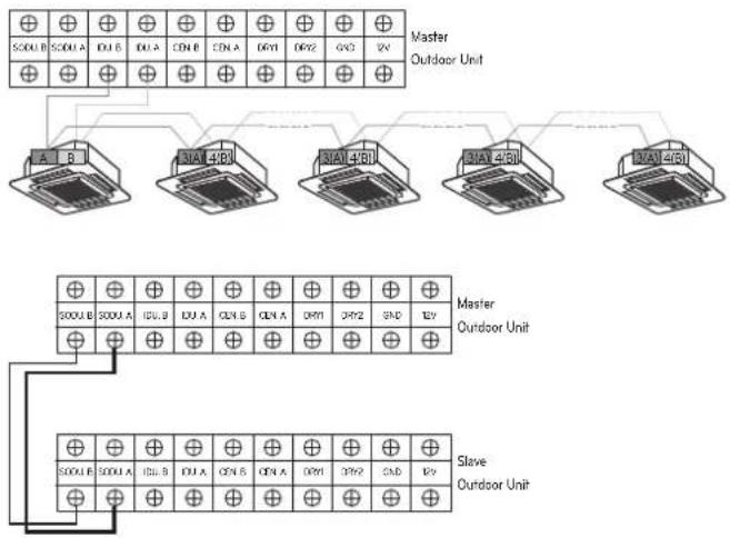
text_image
Master Outdoor Unit A B 3/A 4/B 3/A 4/B1 3/A 4/B1 3/A 4/B1 Master Outdoor Unit 3/A 4/B 3/A 4/B1 3/A 4/B1 Slave Outdoor Unit- It is not the point to make ground connection.
- Make sure that terminal number of master and slave outdoor units are matched.(A-A,B-B)
3 Outdoor Units-3 ∅, 460 V
When the power source is connected In series between the units.
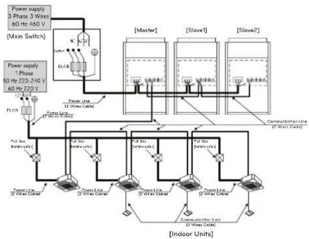
flowchart
graph TD
    A["Power supply 3 Phase 3 Wires 60 Hz 460 V (Main Switch)"] --> B["ECB"]
    C["Power supply 1 Phase 50 Hz 220-240 V 60 Hz 220 V"] --> D["ELCB"]
    D --> E["Power Line (12 Wires Cable)"]
    E --> F["Power Line (2 Wires Cabo)"]
    F --> G["Pull Box (bonds wire)"]
    G --> H["Power Line (2 Wires Cabo)"]
    H --> I["Pull Box (bonds wire)"]
    I --> J["Power Line (2 Wires Cabo)"]
    J --> K["Power Line (2 Wires Cabo)"]
    K --> L["Power Line (2 Wires Cabo)"]
    L --> M["Power Line (2 Wires Cabo)"]
    M --> N["Power Line (2 Wires Cabo)"]
    N --> O["Power Line (2 Wires Cabo)"]
    O --> P["Power Line (2 Wires Cabo)"]
    P --> Q["Power Line (2 Wires Cabo)"]
    Q --> R["Power Line (2 Wires Cabo)"]
    R --> S["Power Line (2 Wires Cabo)"]
    S --> T["Power Line (2 Wires Cabo)"]
    T --> U["Power Line (2 Wires Cabo)"]
    U --> V["Power Line (2 Wires Cabo)"]
    V --> W["Power Line (2 Wires Cabo)"]
    W --> X["Power Line (2 Wires Cabo)"]
    X --> Y["Power Line (2 Wires Cabo)"]
    Y --> Z["Power Line (2 Wires Cabo)"]
    Z --> AA["Power Line (2 Wires Cabo)"]
    AA --> AB["Power Line (2 Wires Cabo)"]
    AB --> AC["Power Line (2 Wires Cabo)"]
    AC --> AD["Power Line (2 Wires Cabo)"]
    AD --> AE["Power Line (2 Wires Cabo)"]
    AE --> AF["Power Line (2 Wires Cabo)"]
    AF --> AG["Power Line (2 Wires Cabo)"]
    AG --> AH["Power Line (2 Wires Cabo)"]
    AH --> AI["Power Line (2 Wires Cabo)"]
    AI --> AJ["Power Line (2 Wires Cabo)"]
    AJ --> AK["Power Line (2 Wires Cabo)"]
    AK --> AL["Power Line (2 Wires Cabo)"]
    AL --> AM["Power Line (2 Wires Cabo)"]
    AM --> AN["Power Line (2 Wires Cabo)"]
    AN --> AO["Power Line (2 Wires Cabo)"]
    AO --> AP["Power Line (2 Wires Cabo)"]
    AP --> AQ["Power Line (2 Wires Cabo)"]
    AQ --> AR["Power Line (2 Wires Cabo)"]
    AR --> AS["Power Line (2 Wires Cabo)"]
    AS --> AT["Power Line (2 Wires Cabo)"]
    AT --> AU["Power Line (2 Wires Cabo)"]
    AU --> AV["Power Line (2 Wires Cabo)"]
    AV --> AW["Power Line (2 Wires Cabo)"]
    AW --> AX["Power Line (2 Wires Cabo)"]
    AX --> AY["Power Line (2 Wires Cabo)"]
    AY --> AZ["Power Line (2 Wires Cabo)"]
    AZ --> BA["Power Line (2 Wires Cabo)"]
    BA --> BB["Power Line (2 Wires Cabo)"]
    BB --> BC["Power Line (2 Wires Cabo)"]
    BC --> BD["Power Line (2 Wires Cabo)"]
    BD --> BE["Power Line (2 Wires Cabo)"]
    BE --> BF["Power Line (2 Wires Cabo)"]
    BF --> BG["Power Line (2 Wires Cabo)"]
    BG --> BH["Power Line (2 Wires Cabo)"]
    BH --> BI["Power Line (2 Wires Cabo)"]
    BI --> BJ["Power Line (2 Wires Cabo)"]
    BJ --> BK["Power Line (2 Wires Cabo)"]
    BK --> BL["Power Line (2 Wires Cabo)"]
    BL --> BM["Power Line (2 Wires Cabo)"]
    BM --> BN["Power Line (2 Wires Cabo)"]
    BN --> BO["Power Line (2 Wires Cabo)"]
    BO --> BP["Power Line (2 Wires Cabo)"]
    BP --> BQ["Power Line (2 Wires Cabo)"]
    BQ --> BR["Power Line (2 Wires Cabo)"]
    BR --> BS["Power Line (2 Wires Cabo)"]
    BS --> BT["Power Line (2 Wires Cabo)"]
    BT --> BU["Power Line (2 Wires Cabo)"]
    BU --> BV["Power Line (2 Wires Cabo)"]
    BV --> BW["Power Line (2 Wires Cabo)"]
    BW --> BX["Power Line (2 Wires Cabo)"]
    BX --> BY["Power Line (2 Wires Cabo)"]
    BY --> BZ["Power Line (2 Wires Cabo)"]
When the power source is supplied to Each outdoor unit individually.
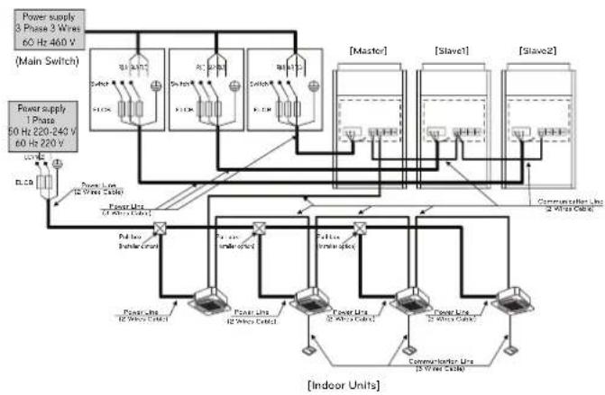
flowchart
graph TD
    A["Power supply 3 Phase 3 Wires 60 Hz 460 V (Main Switch)"] --> B["Switch"]
    A --> C["Switch"]
    A --> D["Switch"]
    B --> E["Power Line (12 Wires Cable)"]
    C --> F["Power Line (12 Wires Cable)"]
    D --> G["Power Line (12 Wires Cable)"]
    E --> H["Power Line (12 Wires Cable)"]
    F --> I["Power Line (12 Wires Cable)"]
    G --> J["Power Line (12 Wires Cable)"]
    H --> K["Power Line (12 Wires Cable)"]
    I --> L["Power Line (12 Wires Cable)"]
    J --> M["Power Line (12 Wires Cable)"]
    K --> N["Power Line (12 Wires Cable)"]
    L --> O["Power Line (12 Wires Cable)"]
    M --> P["Power Line (12 Wires Cable)"]
    N --> Q["Power Line (12 Wires Cable)"]
    O --> R["Power Line (12 Wires Cable)"]
    P --> S["Power Line (12 Wires Cable)"]
    Q --> T["Power Line (12 Wires Cable)"]
    R --> U["Power Line (12 Wires Cable)"]
    S --> V["Power Line (12 Wires Cable)"]
    T --> W["Power Line (12 Wires Cable)"]
    U --> X["Power Line (12 Wires Cable)"]
    V --> Y["Power Line (12 Wires Cable)"]
    W --> Z["Power Line (12 Wires Cable)"]
    X --> AA["Power Line (12 Wires Cable)"]
    Y --> AB["Power Line (12 Wires Cable)"]
    Z --> AC["Power Line (12 Wires Cable)"]
    AA --> AD["Power Line (12 Wires Cable)"]
    AB --> AE["Power Line (12 Wires Cable)"]
    AC --> AF["Power Line (12 Wires Cable)"]
    AD --> AG["Power Line (12 Wires Cable)"]
    AE --> AH["Power Line (12 Wires Cable)"]
    AF --> AI["Power Line (12 Wires Cable)"]
    AG --> AJ["Power Line (12 Wires Cable)"]
    AH --> AK["Power Line (12 Wires Cable)"]
    AI --> AL["Power Line (12 Wires Cable)"]
    AJ --> AM["Power Line (12 Wires Cable)"]
    AK --> AN["Power Line (12 Wires Cable)"]
    AL --> AO["Power Line (12 Wires Cable)"]
    AM --> AP["Power Line (12 Wires Cable)"]
    AN --> AQ["Power Line (12 Wires Cable)"]
    AO --> AR["Power Line (12 Wires Cable)"]
    AP --> AS["Power Line (12 Wires Cable)"]
    AQ --> AT["Power Line (12 Wires Cable)"]
    AR --> AU["Power Line (12 Wires Cable)"]
    AS --> AV["Power Line (12 Wires Cable)"]
    AT --> AW["Power Line (12 Wires Cable)"]
    AU --> AX["Power Line (12 Wires Cable)"]
    AV --> AY["Power Line (12 Wires Cable)"]
    AW --> AZ["Power Line (12 Wires Cable)"]
    AX --> BA["Power Line (12 Wires Cable)"]
    AY --> BB["Power Line (12 Wires Cable)"]
    AZ --> BC["Power Line (12 Wires Cable)"]
    BA --> BD["Power Line (12 Wires Cable)"]
    BB --> BE["Power Line (12 Wires Cable)"]
    BC --> BF["Power Line (12 Wires Cable)"]
    BE --> BG["Power Line (12 Wires Cable)"]
    BF --> BH["Power Line (12 Wires Cable)"]
    BG --> BI["Power Line (12 Wires Cable)"]
    BH --> BJ["Power Line (12 Wires Cable)"]
    BI --> BK["Power Line (12 Wires Cable)"]
    BJ --> BL["Power Line (12 Wires Cable)"]

NOTE
- Field wiring diagram is to be used as a guideline only. Wiring should comply with applicable local and national codes
- ELCB must have function to prevent electrical short and over current at the same time.
- Use copper wires only.
- Unit must be grounded in compliance with the applicable local and national codes.
- ELCB and fuse/breaker must install to the power line

WARNING
- Indoor unit ground lines are required for preventing electrical shock accident during current leakage, Communication disorder by noise effect and motor current leakage (without connection to pipe).
- Don't install an individual switch or electrical outlet to disconnect each of indoor unit separately from the power supply.
• Install the main switch that can interrupt all the power sources in an integrated manner because this system consists of the equipment utilizing the multiple power sources. - If there exists the possibility of reversed phase, lose phase, momentary blackout or the power goes on and off while the product is operating, attach a reversed phase protection circuit locally. Running the product in reversed phase may break the compressor and other parts.
Between Indoor and Master Outdoor unit
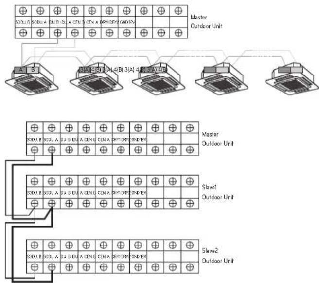
text_image
Master Outdoor Unit A 3 B4(1/2) [A, 4(B) 3(A) 4(B) 5(C) 6(D) Master Outdoor Unit SODU A SODU A DU B DL A CUX A CPU A CPU DRY GND PV SODU B SODU A DU B DL A CUX B CUX A CPU DRY GND EV Slave1 Outdoor Unit SODU B SODU A DU B DL A CUX B CUX A CPU DRY GND EV Slave2 Outdoor Unit- It is not the point to make ground connection.
- Make sure that terminal number of master and slave outdoor units are matched. (A-A,B-B)
Example) Connection of communication cable
[BUS type] [STAR type]
- Connection of communication cable must be installed like below figure between indoor unit to outdoor unit.
- Abnormal operation can be caused by communication defect, when connection of communication cable is installed like below figure(STAR type).
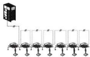
flowchart
graph TD
    A["Server"] --> B["Module 1"]
    A --> C["Module 2"]
    A --> D["Module 3"]
    A --> E["Module 4"]
    A --> F["Module 5"]
    A --> G["Module 6"]
    A --> H["Module 7"]
    A --> I["Module 8"]
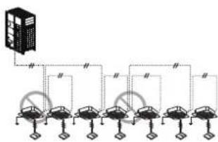
flowchart
graph TD
    A["Central Server"] --> B["Module 1"]
    A --> C["Module 2"]
    A --> D["Module 3"]
    A --> E["Module 4"]
    A --> F["Module 5"]
    A --> G["Module 6"]
    A --> H["Module 7"]
    A --> I["Module 8"]
    A --> J["Module 9"]
    A --> K["Module 10"]
    A --> L["Module 11"]
    A --> M["Module 12"]
    A --> N["Module 13"]
    A --> O["Module 14"]
    A --> P["Module 15"]
    A --> Q["Module 16"]
    A --> R["Module 17"]
    A --> S["Module 18"]
    A --> T["Module 19"]
    A --> U["Module 20"]
    A --> V["Module 21"]
    A --> W["Module 22"]
    A --> X["Module 23"]
    A --> Y["Module 24"]
    A --> Z["Module 25"]
Example) Connection of power and communication cable (UXA)
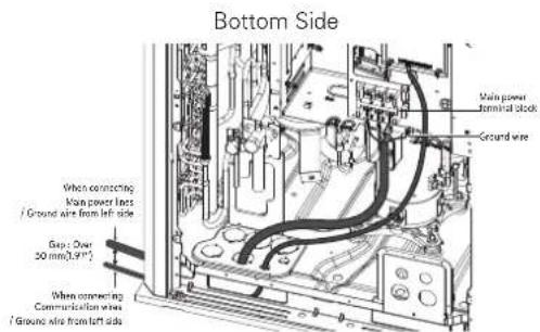
text_image
Bottom Side Main power Terminal block Ground wire When connecting Main power line / Ground wire from left side Gap: Over 50 mm(3.9") When connecting Communication wire / Ground wire from left side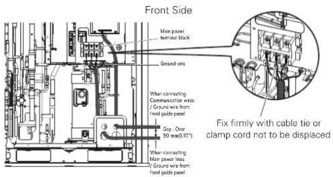
text_image
Front Side Main power narninal block Ground wire When connecting Communication wires / Ground wire from front guide panel Gap Over 50 mm(1.97") When connecting Main power lines / Ground wire from front guide panel Fix firmly with cable tie or clamp cord not to be displaced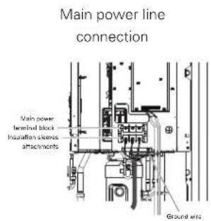
text_image
Main power line connection Main power terminal block Insulation sheeps attachments Ground wire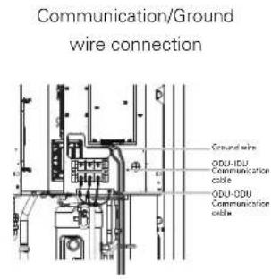
text_image
Communication/Ground wire connection Ground wire ODU-IDU Communication cable ODU-IDU Communication cableCAUTION
It should be wiring power cables or communication cables to avoid interference with the oil level sensor. Otherwise, That oil level sensor would be operated abnormally.
Example) Connection of power and communication cable (UXB)
Bottom Side
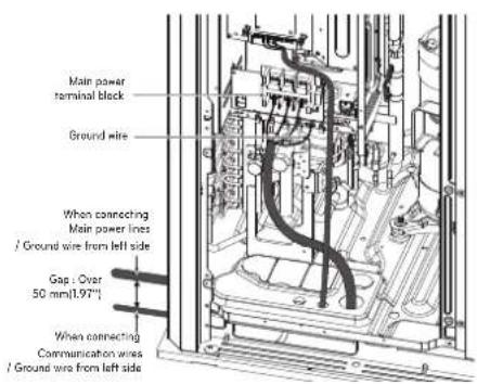
text_image
Main power terminal block Ground wire When connecting Main power lines / Ground wire from left side Gap : Over 50 mm(1.97") When connecting Communication wires / Ground wire from left sideFront Side
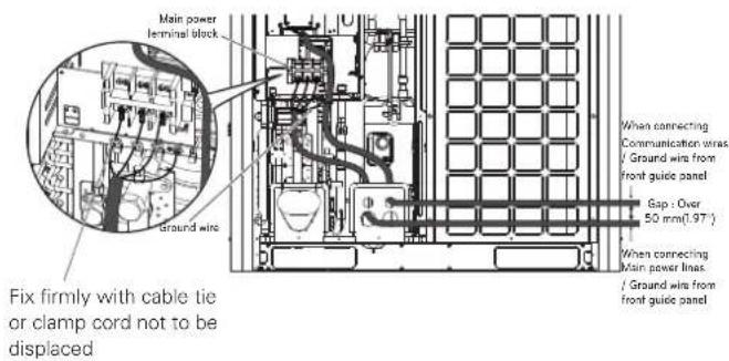
text_image
Main power terminal block ground wire Fix firmly with cable tie or clamp cord not to be displaced When connecting Communication wire / Ground wire from front guide panel Gap : Over 50 mm(1.97°) When connecting Main power lines / Ground wire from front guide panel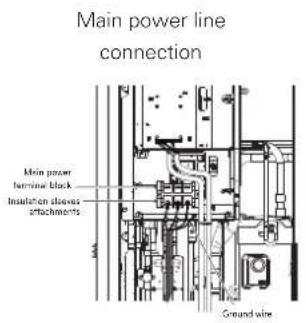
text_image
Main power line connection Main power terminal block Insulation sheaves attachments Ground wire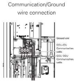
text_image
Communication/Ground wire connection Ground wire CQU-IDU Communication cable CQU-IDU Communicates cable
CAUTION
It should be wiring power cables or communication cables to avoid interference with the oil level sensor. Otherwise, That oil level sensor would be operated abnormally.
Checking the setting of outdoor units
Checking according to DIP switch setting
- You can check the setting values of the Master outdoor unit from the 7 segment LED.
The DIP switch setting should be changed when the power is OFF.
Checking the initial display
The number is sequentially appeared at the 7 segment in 5 seconds after applying the power. This number represents the setting condition.
[Main Board]
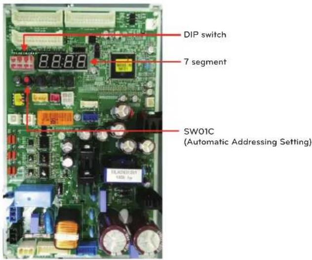
text_image
DIP switch 7 segment SW01C (Automatic Addressing Setting)Quick control Setting
In the factory setting, main PCB DIP switch setting is all "OFF".
- Check and make sure that all the indoor unit model name are ARNU*****4.
- Change the main PCB DIP switch No. 3 "OFF → ON" like below picture.
- Push the reset button.
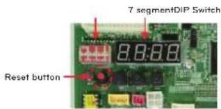
text_image
7 segmentDIP Switch Reset button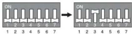
text_image
ON 1 2 3 4 5 6 7 1 2 3 4 5 6 7 ON 1 2 3 4 5 6 7 1 2 3 4 5 6 7- Initial display order
| Order No Mean | ||
| 1 | 10(8RT)~26(22RT) Master unit capacity | |
| 2 | 12(10RT)~24(20RT) Slave 1 unit capacity | |
| 3 | 12(10RT)~24(20RT) Slave 2 unit capacity | |
| 4 | 12(10RT)~24(20RT) Slave 3 unit capacity | |
| 5 | 10(8RT)~96(80RT) Total capacity | |
| 6 | 1 Cooling Only | |
| 7 | 38 380V model | |
| 46 460V model | ||
| 22 220V model | ||
| 8 | 50 Product type | |
| HP 10 | 12 | 14 | 18 | 20 | 22 | 24 | 26 | |||||
| RT 8 | 10 | 12 | 14 | 16 | 18 | 20 | 22 |
• Example) ARUV603BTE(R)5 (50RT)
60 hp 220 V Cooling Only System (Master unit: 18 HP(14 RT), Slave 1: 14 HP(12 RT), Slave 2: 14 HP(12 RT), Slave 3: 14 HP(12 RT))
| 1 2 | 3 4 | 5 6 | 7 | 8 | ||||
| 18 14 | 14 14 | 60 | 1 22 | 50 |
Master/Slave DIP switch setting
- Master Unit
| DIP switch setting | ODU Setting |
| Factory Setting |
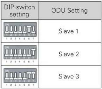 |
Automatic Addressing
The address of indoor units would be set by Automatic Addressing
- Wait for 3 minutes after supplying power. (Master and Slave outdoor units, indoor units)
- Press RED button of the outdoor units for 5 seconds. (SW01C)
- A "88" is indicated on 7-segment LED of the outdoor unit PCB.
- For completing addressing, 2\~7 minutes are required depending on numbers of connected indoor units
- Numbers of connected indoor units whose addressing is completed are indicated for 30 seconds on 7-segment LED of the outdoor unit PCB
- After completing addressing, address of each indoor unit is indicated on the wired remote control display window. (CH01, CH02, CH03, ....., CH06 : Indicated as numbers of connected indoor units)
Main Board
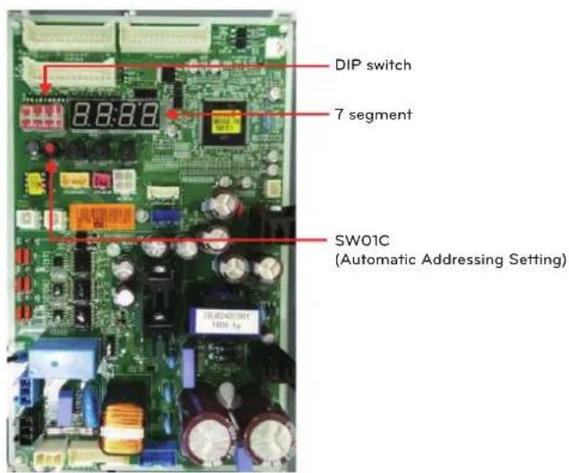
text_image
DIP switch 7 segment SW01C (Automatic Addressing Setting)The Procedure of Automatic Addressing
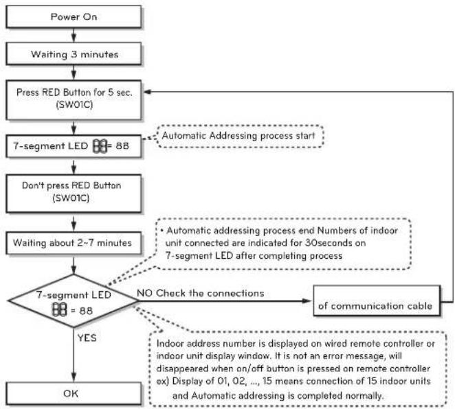
flowchart
graph TD
    A["Power On"] --> B["Waiting 3 minutes"]
    B --> C["Press RED Button for 5 sec. (SW01C)"]
    C --> D["7-segment LED = 88"]
    D --> E["Don't press RED Button (SW01C)"]
    E --> F["Waiting about 2-7 minutes"]
    F --> G{7-segment LED = 88}
    G -->|YES| H["OK"]
    G -->|NO Check the connections| I["of communication cable"]
    I --> C
    C --> J["Automatic Addressing process start"]
    F --> K["Automatic addressing process end Numbers of indoor unit connected are indicated for 30seconds on 7-segment LED after completing process"]
    K --> D
    K --> L["Indoor address number is displayed on wired remote controller or indoor unit display window. It is not an error message, will disappeared when on/off button is pressed on remote controller ex) Display of 01, 02, ..., 15 means connection of 15 indoor units and Automatic addressing is completed normally."]

CAUTION
- In replacement of the indoor unit PCB, always perform Automatic addressing setting again (At that time, please check about using Independent power module to any indoor unit.)
- If power supply is not applied to the indoor unit, operation error occur.
- Automatic Addressing has to be performed after more than 3 minutes to improve indoor unit communition when initial power is supplied.
- Please be sure that all the DIP switch (1\~7) of master outdoor unit is OFF before Automatic Addressing setting
Setting the optional function
Select the mode/function/option/value using '▶', '◀' Button and confirm that using the '●' button after DIP switch No.5 is turned on.

1 2 3 4 5 6 7
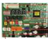
— DIP-SW01
7-Segment
SW04C (X : cancel)
SW03C (▶: forward)
— SW02C (◄: backward)
— SW01C (●: Confirm /
Automatic Addressing)
— SWOID (reset)
| Optional Mode Selection | Function Selection Option Selection | Remarks | ||||
| Content | Display (©) | Content | Display(◄, ►→ ©) | Default | Optional(◄, ►→ ©) | |
| FDD Fdd | Automatic Refrigerant Charging (Cooling) | Fd 1 -- | * Refer FDD guidance | |||
| Refrigerant Amount Check (Cooling) | Fd 3 -- | |||||
| Automatic system check mode (Cooling) | Fd 7 -- | |||||
| All IDU operation (Cooling) | Fd 8 -- | Compulsory Operation for 1 hour | ||||
| Installation Func | High Static Pressure Compensation mode | Fn 2 oFF | oFF,oP1-oP7 | Saving in EEPROM | ||
| Night Low Noise mode | Fn 3 oFF | oFF,oP1-oP12 | ||||
| ODU address setting | Fn 5 0 255 | |||||
| Target Pressure Adjusting | Fn 8 oFF | oFF,oP1-oP4 | ||||
| Low Ambient Kit Fn | 9 oFF on, oFF | |||||
| High Efficiency Mode (Cooling Operation) | Fn 10 oFF on, oFF | |||||
| Auto Dust Removal Mode | Fn 11 oFF | oFF,oP1-oP5 | ||||
| Compressor Max. Frequency Limit | Fn 12 oFF | oFF,oP1-oP9 | ||||
| ODU Fan Max. RPM Limit Mode settling | Fn 13 oFF | oFF,oP1-oP7 | ||||
| Smart Load Control Mode setting | Fn 14 oFF | oFF,oP1-oP3 | ||||
| Humidity Reference Mode setting | Fn 16 on on, oFF | |||||
| Central Control Connection at Indoor Unit side | Fn 19 oFF oFF, on | |||||
| Compressor Input Current Limit mode | Fn 20 oFF | oFF,oP1-oP10 | ||||
| Power Consumption Display on wired remote controller | Fn 21 SPL0 | SPL0, SPL1[Pd10~Pd11] | ||||
| User Idu | Comfort Cooling Mode setting | Id 10 EAch | * Refer Comfort Cooling guidance | Saving in EEPROM | ||
| Service SvC Vaccum Mode SE 3 vACC | - | 1time / 1Selection | ||||
* Functions save in EEPROM will be maintained continuously, though the system power was reset.

CAUTION
- To perform the optional function should be sure that All the IDU is off mode, unless the function will not be performed.
High Static Pressure Compensation mode
This function secures the air flow rate of ODU, in case static pressure has been applied like using duct at fan discharge of ODU.
Static pressure compensation mode setting method
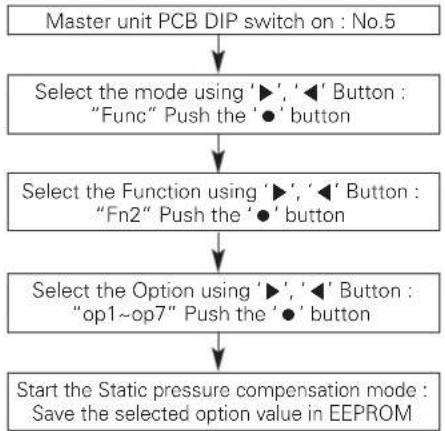
flowchart
graph TD
    A["Master unit PCB DIP switch on : No.5"] --> B["Select the mode using '►', '◄' Button : "Func" Push the '●' button"]
    B --> C["Select the Function using '►', '◄' Button : "Fn2" Push the '●' button"]
    C --> D["Select the Option using '►', '◄' Button : "op1~op7" Push the '●' button"]
    D --> E["Start the Static pressure compensation mode : Save the selected option value in EEPROM"]
FAN Maximum RPM of each step
| Chassis | UXA | UXB | |
| Max. RPM | Standard 880 | 1 000 | |
| Overload / Low Temperature | 1 000 | 1 150 | |
| op1 | 860 | 950 | |
| op2 | 840 | 900 | |
| op3 | 820 | 850 | |
| op4 | 800 | 800 | |
| op5 | 780 | 750 | |
| op6 | 760 | 700 | |
| op7 | 740 | 650 | |
Night Low Noise Function
In cooling mode, this function makes the ODU fan operate at low RPM to reduce the fan noise of ODU at night which has low cooling load.
Night low noise function setting method
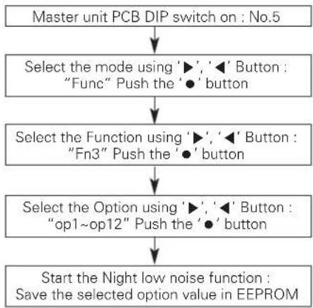
flowchart
graph TD
    A["Master unit PCB DIP switch on : No.5"] --> B["Select the mode using '►', '◄' Button : "Func" Push the '●' button"]
    B --> C["Select the Function using '►', '◄' Button : "Fn3" Push the '●' button"]
    C --> D["Select the Option using '►', '◄' Button : "op1~op12" Push the '●' button"]
    D --> E["Start the Night low noise function : Save the selected option value in EEPROM"]
Time Settings
| Step Judgment | Time(Hr) Operation Time(Hr) | |
| op1 8 9 | ||
| op2 6.5 10.5 | ||
| op3 5 12 | ||
| op4 8 9 | ||
| op5 6.5 10.5 | ||
| op6 5 12 | ||
| op7 8 9 | ||
| op8 6.5 10 | ||
| op9 5 12 | ||
| op10 Continuous operation | ||
| op11 Continuous operation | ||
| op12 Continuous operation | ||
Noise
| Chassis UXA UXB | |||
| Capacity 8~12 hp | 14~20 hp 22~26 hp | ||
| Step Noise(dBA) | |||
| op1~op3,op10 55 | 59 | 60 | |
| op4~op6,op11 52 | 56 | 57 | |
| op7~op9,op12 49 | 53 | 55 | |

CAUTION
- Request installer to set the function during installation.
- If ODU RPM changes, cooling capacity may go down.
Setting the ODU address
Mode setting method
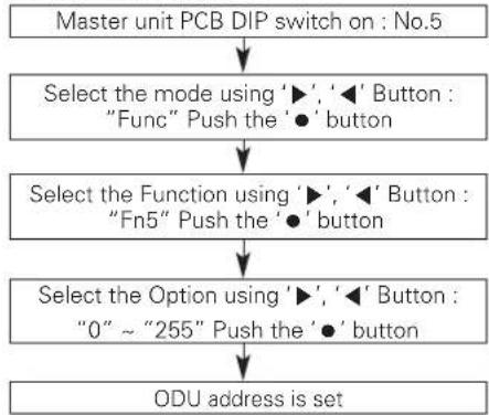
flowchart
graph TD
    A["Master unit PCB DIP switch on : No.5"] --> B["Select the mode using '►', '◄' Button : "Func" Push the '●' button"]
    B --> C["Select the Function using '►', '◄' Button : "Fn5" Push the '●' button"]
    C --> D["Select the Option using '►', '◄' Button : "0" ~ "255" Push the '●' button"]
    D --> E["ODU address is set"]

CAUTION
- Ask an authorized technician to setting a function.
- If use a function, first install a Central controller.
Target pressure adjusting
Mode setting method
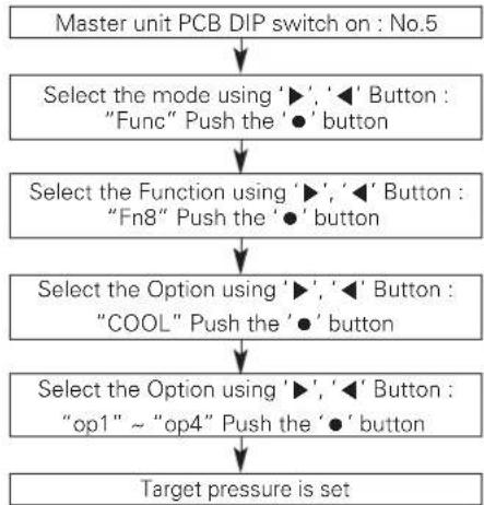
flowchart
graph TD
    A["Master unit PCB DIP switch on : No.5"] --> B["Select the mode using '►', '◄' Button : "Func" Push the '●' button"]
    B --> C["Select the Function using '►', '◄' Button : "Fn8" Push the '●' button"]
    C --> D["Select the Option using '►', '◄' Button : "COOL" Push the '●' button"]
    D --> E["Select the Option using '►', '◄' Button : "op1" ~ "op4" Push the '●' button"]
    E --> F["Target pressure is set"]
Setting
| Mode | Purpose | Condensing temperature variation | Evaporating temperature variation | |
| Heat | Cool | |||
| op1 | Increase capacity | Increase capacity | +2 °C(35.6 °F) | -3 °C(37.4 °F) |
| op2 | Decrease power consumption | Increase capacity | +2 °C(35.6 °F) | -1.5 °C(-34.7 °F) |
| op3 | Decrease power consumption | Decrease power consumption | -4 °C(-39.2 °F) | +2.5 °C(36.5 °F) |
| op4 | Decrease power consumption | Decrease power consumption | -6 °C(-42.8 °F) | -4.5 °C(-40.1 °F) |

CAUTION
- Ask an authorized technician to setting a function.
- If do not use a function, set an off-mode.
- Change a power consumption or capacity.
Low Ambient Kit
Mode setting method
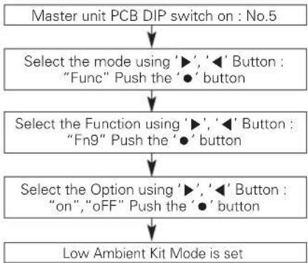
flowchart
graph TD
    A["Master unit PCB DIP switch on : No.5"] --> B["Select the mode using '►', '◄' Button : "Func" Push the '●' button"]
    B --> C["Select the Function using '►', '◄' Button : "Fn9" Push the '●' button"]
    C --> D["Select the Option using '►', '◄' Button : "on", "oFF" Push the '●' button"]
    D --> E["Low Ambient Kit Mode is set"]
* Reference for functional logic of I/O Module
High Efficiency Mode (Cooling Operation)
Target low pressure will change according to ODU temperature during the cooling operation.
Mode setting method
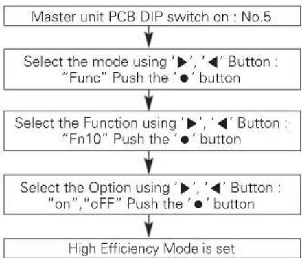
flowchart
graph TD
    A["Master unit PCB DIP switch on : No.5"] --> B["Select the mode using '►', '◄' Button : "Func" Push the '●' button"]
    B --> C["Select the Function using '►', '◄' Button : "Fn10" Push the '●' button"]
    C --> D["Select the Option using '►', '◄' Button : "on", "oFF" Push the '●' button"]
    D --> E["High Efficiency Mode is set"]
Auto Dust Removal Mode
The ability to set reverse run outdoor fan to remove dust, heat exchanger.
Mode setting method
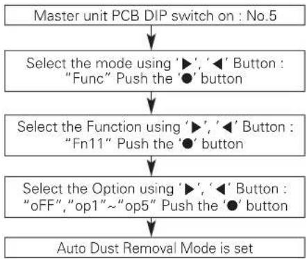
flowchart
graph TD
    A["Master unit PCB DIP switch on : No.5"] --> B["Select the mode using '►', '◄' Button : "Func" Push the '●' button"]
    B --> C["Select the Function using '►', '◄' Button : "Fn11" Push the '●' button"]
    C --> D["Select the Option using '►', '◄' Button : "oFF", "op1"~"op5" Push the '●' button"]
    D --> E["Auto Dust Removal Mode is set"]
Mode Setting
| Setting | Operation time | Operating time | Repeat cycle | Detail of function |
| op1 | Stop +2 hour | 5 minutes | 2hour | After product stopped 2 hour, fan operating 5 min(Repeated every 2 hours) |
| op2 | stop +5 minutes | 3 minutes | Twice in 2 hour | after product stopped 5 minutes, fan operating 3 min (Limited to two times within 2 hours) |
| op3 | stop +5 minutes | 3 minutes | 1 time | after product stopped 2 hour, fan operating 5 min(Repeated every 2 hours) |
| op4 | Stop +1 minutes | 1 minutes | 1 time | after product stopped 5 minutes, fan operating 3 min(when io module connection/one-time operation) |
| op5 | Stop +1 minutes | 1 minutes | Low speed | after product stopped 1 minutes, fan operating 1 min(every time the product stops) |
Compressor Max. Frequency Limit
Mode setting method
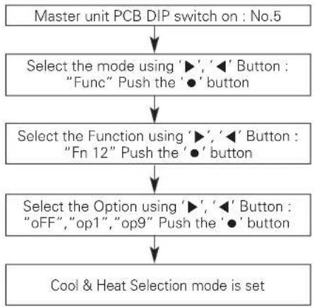
flowchart
graph TD
    A["Master unit PCB DIP switch on : No.5"] --> B["Select the mode using '►', '◄' Button : "Func" Push the '●' button"]
    B --> C["Select the Function using '►', '◄' Button : "Fn 12" Push the '●' button"]
    C --> D["Select the Option using '►', '◄' Button : "oFF", "op1", "op9" Push the '●' button"]
    D --> E["Cool & Heat Selection mode is set"]
Function setting
| Setting Inverter (Hz) | |
| oFF - | |
| op1 143 Hz | |
| op2 135 Hz | |
| op3 128 Hz | |
| op4 120 Hz | |
| op5 113 Hz | |
| op6 105 Hz | |
| op7 98 Hz | |
| op8 90 Hz | |
| op9 83 Hz |
CAUTION
- Ask an authorized technician to setting a function.
- If use a function, first install a Central controller.
ODU Fan Max. RPM Limit
Mode setting method
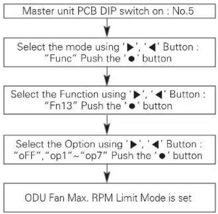
flowchart
graph TD
    A["Master unit PCB DIP switch on : No.5"] --> B["Select the mode using '►', '◄' Button : "Func" Push the '●' button"]
    B --> C["Select the Function using '►', '◄' Button : "Fn13" Push the '●' button"]
    C --> D["Select the Option using '►', '◄' Button : "oFF", "op1"~"op7" Push the '●' button"]
    D --> E["ODU Fan Max. RPM Limit Mode is set"]
MAX. RPM Limit Setting
| Chassis UXA UXB | |||
| Fan MAX. RPM Limit (RPM) | oFF 880 1000 | ||
| oP1 -20 -50 | |||
| oP2 -40 -100 | |||
| oP3 -60 -150 | |||
| oP4 -80 -200 | |||
| oP5 -100 -250 | |||
| oP6 -120 -300 | |||
| oP7 -140 -350 | |||
SLC (Smart Load Control)
Function for set the variable target pressure which for the high efficiency and comport operation depend on ODU load.
Mode setting method
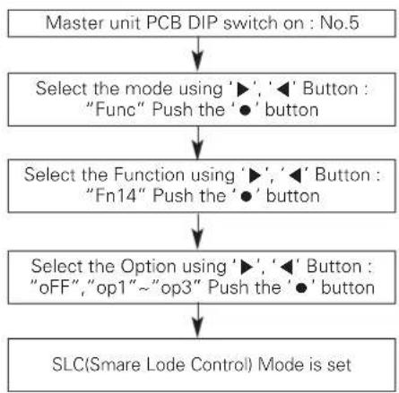
flowchart
graph TD
    A["Master unit PCB DIP switch on : No.5"] --> B["Select the mode using '►', '◄' Button : "Func" Push the '●' button"]
    B --> C["Select the Function using '►', '◄' Button : "Fn14" Push the '●' button"]
    C --> D["Select the Option using '►', '◄' Button : "oFF", "op1" ~ "op3" Push the '●' button"]
    D --> E["SLC(Smare Lode Control) Mode is set"]
SLC(Smare Lode Control) Mode
| Setting Mode Detail of function | |
| oFF Not Setting - | |
| oP1 Smooth Mode Slowly control, a target pressure value | |
| oP2 Normal Mode Normal control, a target pressure value | |
| oP3 Peak Mode Fast control, a target pressure value | |
Humidity Reference
Mode setting method

flowchart
graph TD
    A["Master unit PCB DIP switch on : No.5"] --> B["Select the mode using '►', '◄' Button : "Func" Push the '●' button"]
    B --> C["Select the Function using '►', '◄' Button : "Fn16" Push the '●' button"]
    C --> D["Select the Option using '►', '◄' Button : "oFF", "on" Push the '●' button"]
    D --> E["Humidity Reference Control mode is set"]
Mode setting
-on:using humidity sensor
- oFF:not setting
- When used cooling operation of SLC function, it will improve energy efficiency because evaporation temperature will be decreased
Central Control Connection at Indoor Unit side
Mode setting method
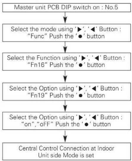
flowchart
graph TD
    A["Master unit PCB DIP switch on : No.5"] --> B["Select the mode using '►', '◄' Button : "Func" Push the '●' button"]
    B --> C["Select the Function using '►', '◄' Button : "Fn16" Push the '●' button"]
    C --> D["Select the Option using '►', '◄' Button : "Fn19" Push the '●' button"]
    D --> E["Select the Option using '►', '◄' Button : "on", "oFF" Push the '●' button"]
    E --> F["Central Control Connection at Indoor Unit side Mode is set"]
Compressor Input Current Limit
System Input Current Control
Mode setting method
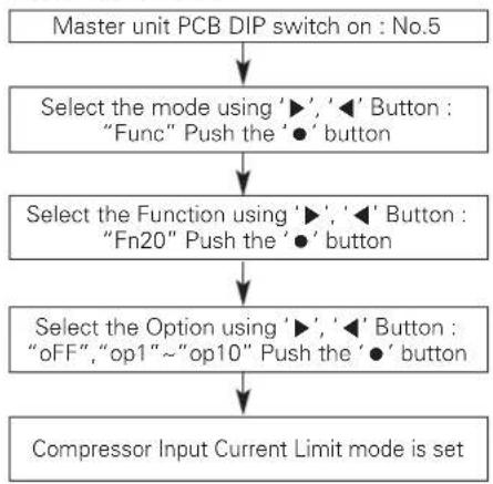
flowchart
graph TD
    A["Master unit PCB DIP switch on : No.5"] --> B["Select the mode using '►', '◄' Button : "Func" Push the '●' button"]
    B --> C["Select the Function using '►', '◄' Button : "Fn20" Push the '●' button"]
    C --> D["Select the Option using '►', '◄' Button : "oFF", "op1"~"op10" Push the '●' button"]
    D --> E["Compressor Input Current Limit mode is set"]
Compressor Input Current Limit
- Ask an authorized technician to setting a function.
- If do not use a function, set an off-mode.
- If use a function, capacity may go down.
Power Consumption Display on wired remote controller
Mode setting method
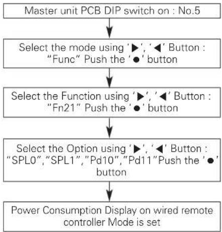
flowchart
graph TD
    A["Master unit PCB DIP switch on : No.5"] --> B["Select the mode using '►', '◄' Button : "Func" Push the '●' button"]
    B --> C["Select the Function using '►', '◄' Button : "Fn21" Push the '●' button"]
    C --> D["Select the Option using '►', '◄' Button : "SPL0", "SPL1", "Pd10", "Pd11" Push the '●' button"]
    D --> E["Power Consumption Display on wired remote controller Mode is set"]
| Setting Detail of function |
| SPL0 Not used Smart plug logic |
| SPL1 Using smart plug logic |
| Pd10 Not installation |
| Pd11 PDI was installed |
Comfort Cooling operation
It is function to reduce the ODU energy consumption by the continuous operation without thermo off.
Mode setting method
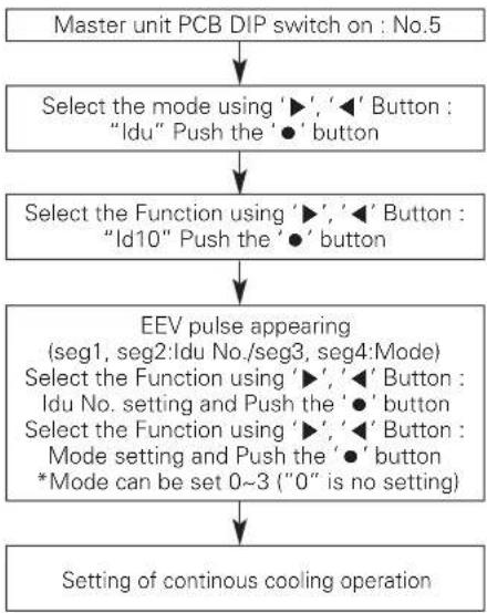
flowchart
graph TD
A["Master unit PCB DIP switch on : No.5"] --> B["Select the mode using '►', '◄' Button : "Idu" Push the '●' button"]
B --> C["Select the Function using '►', '◄' Button : "Id10" Push the '●' button"]
C --> D["EEV pulse appearing (seg1, seg2:Idu No./seg3, seg4:Mode)<br>Select the Function using '►', '◄' Button : Idu No. setting and Push the '●' button<br>Select the Function using '►', '◄' Button : Mode setting and Push the '●' button *Mode can be set 0~3 ("0" is no setting)"]
D --> E["Setting of continuous cooling operation"]
Setting of continuous cooling operation
| Mode setting Effect |
| 0 No setting |
| 1 Cooling capacity low,Power consumption low |
| 2 Cooling capacity mid,Power consumption mid |
| 3 Cooling capacity high,Power consumption high |
Self-Diagnosis Function
Error Indicator
- This function indicates types of failure in self-diagnosis and occurrence of failure for air condition.
- Error mark is displayed on display window of indoor units and wired remote controller, and 7-segment LED of outdoor unit control board as shown in the table.
- If more than two troubles occur simultaneously, lower number of error code is first displayed.
- After error occurrence, if error is released, error LED is also released simultaneously.
Error Display
1st, 2nd, 3rd LED of 7-segment indicates error number, 4th LED indicates unit number. ^* = 1: Master, 2: Slave 1, 3: Slave 2, 4: Slave 3)
Ex) 1051 : Error occurrence with error number 105 at No. 1 outdoor unit (=Master unit) In case of indoor unit error occurrence, the error number is only shown at remote controller without 7 segment LED of outdoor unit.
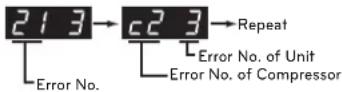
Ex) CH → 01 : Error occurrence with error number 01 (at remote controller) In case of compressor error occurrence, 7 segment LED of outdoor unit control board will display its error number alternately with compressor number.
Ex) 213 → C23 : It means that compressor error occurred with Error No. 21 at No. 3 Outdoor unit (=Slave2)
* Refer to the DX-Venitilation manual for DX-Venitilation error code.
| Display Title Cause of Error | |||||
| Indoor unit related errorOutdoor unit related error | 0 | 1 | - | Air temperature sensor of indoor unit | Air temperature sensor of indoor unit is open or short |
| 0 | 2 | - | Inlet pipe temperature sensor of indoor unit | Inlet pipe temperature sensor of indoor unit is open or short | |
| 0 3 | - | Communication error : wired remote controller ↔ indoor unit | Failing to receive wired remote controller signal in indoor unit PCB | ||
| 0 4 | - Drain pump Malfunction of drain pump | ||||
| 0 5 | - | Communication error : outdoor unit <> indoor unit | Failing to receive outdoor unit signal in indoor unit PCB | ||
| 0 | 6 | - | Outlet pipe temperature sensor of indoor unit | Outlet pipe temperature sensor of indoor unit is open or short | |
| 0 | 8 | - | Hydro Kit Hot water storage tank Temperature sensor | Pipe temperature sensor is open or short | |
| 0 9 | - Indoor EEPROM Error | In case when the serial number marked on EEPROM of Indoor unit is 0 or FFFFFFF | |||
| 1 0 | - Poor fan motor operation | Disconnecting the fan motor connector / Failure of indoor fan motor lock | |||
| 1 1 | - | Communication error : Hydro Kit Indoor unit <> Inv.PCB | Failing to receive Inv. PCB signal in indoor unit | ||
| 1 2 | - Hydro Kit Inv.PCB error Hydro Kit Inv.PCB error | ||||
| 1 | 3 | - | Hydro Kit Solar heat piping temperature sensor error | Pipe temperature sensor is open or short | |
| 1 4 | - Hydro Kit Indoor unit Flow switch error Flow switch flow detection error | ||||
| 1 | 5 | - | Hydro Kit Liquid pipe Strange overheat Error | Temperature sensor defective or hot water inflow | |
| 1 | 6 | - | Hydro KitIndoor unit Inlet and Outlet pipe Temperature sensor Error | Pipe temperature sensor is open or short | |
| 1 | 7 | - | Hydro Kit Indoor unit Inlet pipe Temperature sensor ErrorOutside air Introduction duct Inlet pipe Temperature sensor Error | Pipe temperature sensor is open or short | |
| 1 | 8 | - | Hydro Kit Indoor unit Outlet pipe Temperature sensor Error | Pipe temperature sensor is open or short | |
| 2 1 | * | Outdoor Unit Inverter Compressor IPM Fault | Outdoor Unit Inverter Compressor Drive IPM Fault | ||
| 2 2 | * | Inverter PCB Input Over Current(RMS) of Master Outdoor Unit | Outdoor Unit Inverter PCB Input Current excess (RMS) | ||
| 2 3 | * | Outdoor Unit Inverter Compressor DC Link Low or High Voltage | System is turned off by Master Outdoor Unit DC Link Low/High Voltage. | ||
| 2 4 | * Outdoor Unit High Pressure Switch | System is turned off by Master Outdoor Unit high pressure switch. | |||
| 2 5 | * | Outdoor Unit Input Voltage High/ Low Voltage | Over 310V or below 143V (ARUV***BTE(R)5)Over 598V or below 320V (ARUV***DTE5) | ||
• 1 : Master outdoor unit error, 2 : salve 1 outdoor unit error
- 3: slave2 outdoor unit error, 4: slave3 outdoor unit error
| Display Title Cause of Error | ||||||
| Outdoor unit related error | 2 6 | * Outdoor | Unit Inverter Compressor Start Failure | The first start failure by Outdoor Unit Inverter Compressor abnormality or Compressor locked | ||
| 2 | 9 | * | Outdoor Unit Inverter Compressor Over Current | Outdoor Unit Inverter Compressor Fault OR Drive Fault | ||
| 3 2 | * | Outdoor Unit Inverter Compressor1 High Discharge Temperature | Outdoor Unit Inverter Compressor1 High Discharge Temperature | |||
| 3 3 | * | Outdoor Unit Inverter Compressor2 High Discharge Temperature | Outdoor Unit Inverter Compressor2 High Discharge Temperature | |||
| 3 4 | * High Pressure of Outdoor Unit High Pressure of Outdoor Unit | |||||
| 3 5 | * Low Pressure of Outdoor Unit Low Pressure of Outdoor Unit | |||||
| 4 0 | * Outdoor | Unit Inverter Compressor CT Sensor Fault Outdoor Unit | Unit Inverter Compressor CT Sensor open or short | |||
| 4 1 | * | Outdoor Unit Inverter Compressor1 Discharge Temperature Sensor Fault | Outdoor Unit Inverter Compressor Discharge Temperature Sensor open or short | |||
| 4 2 | * Outdoor | Unit Low Pressure Sensor Fault Outdoor Unit Low Pressure Sensor open or short | ||||
| 4 3 | * Outdoor | Unit High Pressure Sensor Fault Outdoor Unit High Pressure Sensor open or short | ||||
| 4 | 4 | * | Outdoor Unit Air Temperature Sensor Fault | Outdoor Unit Air Temperature Sensor open or short | ||
| 4 5 | * | Outdoor Unit Heat Exchanger Temperature Sensor (Front side) Fault | Outdoor Unit Heat Exchanger Temperature Sensor(Front side) open or short | |||
| 4 | 6 | * | Outdoor Unit Suction Temperature Sensor Fault | Outdoor Unit Suction Temperature Sensor open or short | ||
| 4 7 | * | Outdoor Unit Inverter Compressor2 Discharge Temperature Sensor Fault | Outdoor Unit Inverter Compressor2 Discharge Temperature Sensor open or short | |||
| 4 9 | * Outdoor | Unit Faulty IPM Temperature Sensor Outdoor Unit IPM Temperature Sensor short/open | ||||
| 5 | 0 | * | Omitting connection of R, S, T power of Outdoor Unit | Omitting connection of outdoor unit | ||
| 5 1 | * Excessive capacity of indoor units | Excessive connection of indoor units compared to capacity of Outdoor Unit | ||||
| 5 | 2 | * | Communication error: inverter PCB → Main PCB | Failing to receive inverter signal at main PCB of Outdoor Unit | ||
| 5 | 3 | * | Communication error: indoor unit → Main PCB of Outdoor Unit | Failing to receive indoor unit signal at main PCB of Outdoor Unit. | ||
| 5 | 7 | * | Communication error: Main PCB → inverter PCB | Failing to receive signal main PCB at inverter PCB of Outdoor Unit | ||
| 6 0 | * Inverter | PCB EEPROM Error of Master Outdoor Unit Access Error of Inverter PCB of Outdoor Unit | ||||
| 6 2 | * Outdoor | Unit Inverter Heatsink High Temperature | System is turned off by Outdoor Unit Inverter Heatsink High Temperature | |||
| 6 | 5 | * | Outdoor Unit Inverter Heatsink Temperature Sensor Fault | Outdoor Unit Inverter Heatsink Temperature Sensor open or short | ||
| 6 7 | * Outdoor | Unit Fan Lock Restriction of Outdoor Unit | ||||
| 7 1 | * Inverter | CT Sensor Error of Master Outdoor Unit Inverter CT Sensor open or short of Outdoor Unit | ||||
| 7 5 | * Outdoor | Unit Fan CT Sensor Error Outdoor Unit Fan CT Sensor open or short | ||||
| 7 7 | * Outdoor | Unit Fan Over Current Error Outdoor Unit Fan Current is over 6A | ||||
| 7 9 | * Outdoor | Unit Fan Start Failure Error | The first start failure by Outdoor Unit Fan abnormality or Fan locked | |||
| 8 6 | * Outdoor | Unit Main PCB EEPROM Error | Communication Fail Between Outdoor Unit Main MICOM and EEPROM or omitting EEPROM | |||
| 8 7 | * Outdoor | Unit Fan PCB EEPROM Error | Communication Fail Between Outdoor Unit Fan MICOM and EEPROM or omitting EEPROM | |||
| 1 | 0 | 4 | * | Communication Error Between Outdoor Unit and Other Outdoor Unit | Failing to receive Slave Unit signal at main PCB of Outdoor Unit | |
| 1 | 0 | 5 | * | Outdoor Unit Fan PCB Communication Error | Failing to receive fan signal at main PCB of Outdoor unit | |
| 1 | 0 | 6 | * | Outdoor Unit Fan IPM Fault Error | Instant Over Current at Outdoor Unit Fan IPM | |
| Display Title Cause of Error | ||||||
| Outdoor unit related error | 1 | 0 | 7 | * | Outdoor Unit Fan DC Link Low Voltage Error | Outdoor Unit Fan DC Link Input Voltage is under 50V |
| 1 | 1 | 3 | * | Outdoor Unit Liquid pipe Temperature Sensor Error | Liquid pipe temperature sensor of Outdoor Unit is open or short | |
| 1 | 4 | * | Outdoor Unit Subcooling Inlet Temperature Sensor Error | Outdoor Unit Subcooling Inlet Temperature Sensor Error | ||
| 1 | 1 | 5 | * | Outdoor Unit Subcooling Outlet Temperature Sensor Error | Outdoor Unit Subcooling Outlet Temperature Sensor Error | |
| 1 | 6 | * | Outdoor | Unit Oil Level Sensor Error Oil Level Sensor of Outdoor Unit is open or short | ||
| 1 | 4 | 5 | * | Outdoor unit Main Board - External Board communication Error | Outdoor unit Main Board - External Board communication Error | |
| 1 | 5 | 0 | * | Unit Discharge Superheat not satisfied | Outdoor Unit Compressor Discharge Superheat not satisfied during 5 Min. | |
| 1 | 5 | 1 | * | Failure of operation mode conversion at Outdoor Unit | Failure of operation mode conversion at Outdoor Unit | |
| 1 | 5 | 3 | * | Outdoor Unit Heat Exchanger Temperature Sensor (upper part) Fault | Outdoor Unit Heat Exchanger Temperature Sensor (upper part) Fault | |
| 1 | 5 | 4 | * | Outdoor Unit Heat Exchanger Temperature Sensor (lower part) Fault | Outdoor Unit Heat Exchanger Temperature Sensor(lower part) open or short | |
| 1 | 8 | 2 | * | Outdoor unit External Board Main-Sub Micom communication Error | Outdoor Unit Main Board Main-Sub Micom communication failed | |
| 1 | 8 | 7 | Hydro - | Kit P,HEX bursting error | Inlet water temperature is below 5 degree or water temperature error during defrosting operation. | |
| 1 | 9 | 3 | * | Unit Fan Heatsink High Temperature | System is turned off by Outdoor Unit Fan Heatsink High Temperature | |
| 1 | 9 | 4 | * | Outdoor Unit Fan Heatsink Temperature Sensor Fault | Outdoor Unit Fan Heatsink Temperature Sensor open or short | |
| Network error | 2 | 4 | 2 | * | Network error of cntral controller Communication wiring defect | |
CAUTION FOR REFRIGERANT LEAK
The installer and system specialist shall secure safety against leakage according to local regulations or standards.
The following standards may be applicable if local regulations are not available.
Introduction
Though the R410A refrigerant is harmless and incombustible itself, the room to equip the air conditioner should be large to such an extent that the refrigerant gas will not exceed the Concentration limit even if the refrigerant gas leaks in the room.
Concentration limit
Concentration limit is the limit of Freon gas concentration where immediate measures can be taken without hurting human body when refrigerant leaks in the air. The Concentration limit shall be described in the unit of [kg/m^3 (lbs/ft ^3 )] (Freon gas weight per unit air volume) for facilitating calculation.
Concentration limit: 0.44 kg/m ^3 (0.028 lbs/ft ^3 ) (R410A)
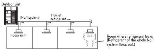
flowchart
graph LR
    A["Outdoor unit"] --> B["(No.1 system)"]
    B --> C["Indoor unit"]
    C --> D["Flow of refrigerant"]
    D --> E["Room where refrigerant leaks (Refrigerant of the whole No.1 system flows out.)"]
    E --> F["{ ... }"]
Checking procedure of limiting concentration
Check Concentration limit along following steps and take appropriate measure depending on the situation.
Calculate amount of all the replenished refrigerant [kg (lbs)] per each refrigerant system.
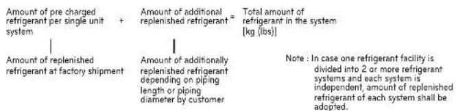
text_image
Amount of pre charged refrigerant per single unit + Amount of additional replenished refrigerant = Total amount of refrigerant in the system system [kg (lbs)] Amount of replenished refrigerant at factory shipment Amount of additionally replenished refrigerant depending on piping length or piping diameter by customer Note : In case one refrigerant facility is divided into 2 or more refrigerant systems and each system is independent, amount of replenished refrigerant of each system shall be adopted.Calculate refrigerant concentration level
Calculate the volume of the room where indoor unit is installed as single room or the smallest room.
- Without partition
- With partition but opened which serve passage of air to adjoining room
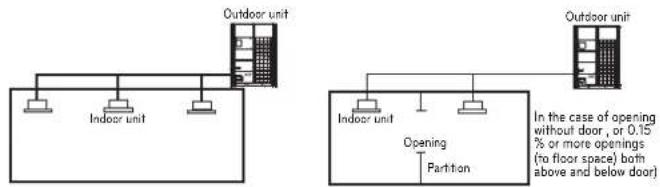
text_image
Outdoor unit Indoor unit Outdoor unit Indoor unit Opening Partition In the case of opening without door, or 0.15 % or more openings (to floor space) both above and below door)- With partition and without opening which serve as passage of air to adjoining room
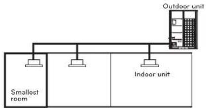
flowchart
graph TD
    A["Smallest room"] --> B["Indoor unit"]
    C["Outdoor unit"] --> B
    B --> D["Indoor unit"]
Calculate refrigerant concentration
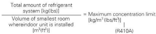
text_image
Total amount of refrigerant system [kg(lbs)] Volume of smallest room whereindoor unit is installed [m³(ft²)] = Maximum concentration limit [kg/m³ (lbs/ft³)] (R410A)- In case the result of calculation exceeds the Concentration limit, perform the same calculations by shifting to the second smallest, and the third smallest rooms until at last the result is below the Concentration limit.
In case the concentration exceeds the limit
When the concentration exceeds the limit, change original plan or take one of the countermeasures shown below:
• Countermeasure 1
Provide opening for ventilation.
Provide 0.15 % or More size of opening to floor space both above and below door, or provide opening without door.
- Countermeasure 2
Provide gas leak alarm linked with mechanical ventilator.
- Countermeasure 3
Reducing the system's refrigerant quantity by deviding into smaller separate system.
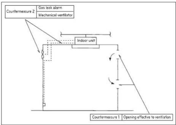
flowchart
graph TD
    A["Countermeasure 2"] --> B["Gas leak alarm"]
    B --> C["Mechanical ventilator"]
    D["Indoor unit"] --> E["Opening effective to ventilation"]
    F["Countermeasure 1"] --> G["Opening effective to ventilation"]
Pay a special attention to the place, such as a basement, etc. where refrigerant can stay, since refrigerant is heavier than air.
INSTALLATION GUIDE AT THE SEASIDE

CAUTION
• Air conditioners should not be installed in areas where corrosive gases, such as acid or alkaline gas, are produced.
- Avoid installing the product where it could be exposed to sea wind (salty wind) directly. It can result corrosion on the product. Corrosion, particularly on the condenser and evaporator fins, could cause product malfunction or inefficient operation.
- If outdoor unit is installed close to the seaside, should avoid direct exposure to the sea wind.
Selecting the location(Outdoor Unit)
If the outdoor unit is to be installed close to the seaside, direct exposure to the sea wind should be avoided. Install the outdoor unit on the opposite side of the sea wind direction.
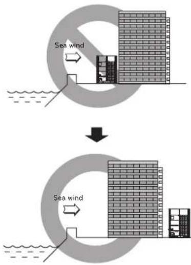
text_image
Sea wind Sea windIn case, to install the outdoor unit on the seaside, set up a windbreak not to be exposed to the sea wind.
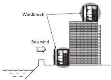
text_image
Windbreak Sea wind- It should be strong enough like concrete to prevent the sea wind from the sea.
- The height and width should be more than 150 % of the outdoor unit.
- It should be kept more than 70 cm (2.3 ft) of distance between outdoor unit and the windbreak for smooth air flow.
Select a well-drained place.
- Periodic (1 times per 6 month) cleaning of the dust or salt particles stuck on the heat exchanger is necessary by using clean water
If there is improper installation or maintenance not complying with the installation guide, product's performance and reliability is not guaranteed.
Model Designation
Product information
• Product Name : Air conditioner
- Model Name :
| Product Sales Name Model Factory Name | |
| ARUx***yTE5 series | |
| x = N (Heat Pump), V (Cooling Only), M (Heat Recovery / Heat Pump) | |
| y = B (220-240 V),D (460 V) | |
| *** = Numeric; (Cooling capacity) |
• Additional information : Serial number is refer to the bar code on the product.
Airborne Noise Emission
The A-weighted sound pressure emitted by this product is below 70 dB.
** The noise level can vary depending on the site.
The figures quoted are emission level and are not necessarily safe working levels.
Whilst there is a correlation between the emission and exposure levels, this cannot be used reliably to determine whether or not further precautions are required.
Factor that influence the actual level of exposure of the workforce include the characteristics of the work room and the other sources of noise, i.e. the number of equipment and other adjacent processes and the length of time for which an operator exposed to the noise. Also, the permissible exposure level can vary from country to country.
This information, however, will enable the user of the equipment to make a better evaluation of the hazard and risk.

LG
Life's Good