
HAS-WM06 - Wall mount HITACHI - Free user manual and instructions
Find the device manual for free HAS-WM06 HITACHI in PDF.

| Product Type | Wall mount for projector |
| Brand | Hitachi |
| Model | HAS-WM06 |
| Weight | 7.1 kg |
| Maximum Projector Weight | 7.6 kg |
| Compatible Projectors | Hitachi LP-AW4001, LP-AW3001, LP-AX3001 |
| Material | Steel |
| Adjustments | Horizontal position ±5°, horizontal keystone ±5°, vertical keystone ±5°, lateral position ±50 mm, image size 308 mm, vertical position ±35 mm |
| Included Items | Arm assembly, base bracket (center and sides), adjusting block, bracket, front cap, cable covers, screws, wrench, template sheet, manual |
| Wall Fasteners Required | M8 anchor bolts, at least 8, pull-out strength ≥2000 N each |
| Cable Management | Cable clamp and cable covers included |
| Installation | Professional installation recommended; follow manual for safe mounting |
| Safety | Do not modify; use only specified screws; inspect annually |
| Maintenance | Annual inspection for loose screws and damage |
| Warranty | See dealer or service center |
Frequently Asked Questions - HAS-WM06 HITACHI
User questions about HAS-WM06 HITACHI
0 question about this device. Answer the ones you know or ask your own.
Ask a new question about this device
Download the instructions for your Wall mount in PDF format for free! Find your manual HAS-WM06 - HITACHI and take your electronic device back in hand. On this page are published all the documents necessary for the use of your device. HAS-WM06 by HITACHI.
USER MANUAL HAS-WM06 HITACHI
Thank you for purchasing a wall mount unit specially designed for Hitachi projectors.
Be sure to read this manual and the User's Manual supplied with the projector before use so you will know how to install it properly. After you have finished reading these documents, put them away in a safe place for future reference.
Disclaimer
- The content of this manual and the specifications of the product it describes are subject to change without prior notice.
- Note that Hitachi will accept no liability whatsoever for injuries and damages arising from incorrect use or handling that exceeds normal operating limits.
Table of Contents
Disclaimer .... 1
Table of Contents ...... 1
Safety Symbols 1
Overview....2
Installation Precautions 2
Tools needed for installation 2
To the customer 3
To service personnel 3
Routine Inspections .... 3
Contents of this package .... 4
Base bracket attachment diagram ..... 5
Sheet projecting distance table 5
Template sheet usage 6
Installation procedure 7
① Wall mounting of the base assembly ..... 7
② Extending the arm bracket (IN) 8
③ Attaching Adjusting block (D) 8
④ Installation of the vertical adjustment screw (L) of the arm ... 9
⑤ Mounting of the arm assembly (A) 9
⑥ Installation of the arm fixing strut screw (K) ...10
⑦ Installation of the strut cover bracket (M) ...10
⑧ Removal and storage of screws .....11
⑨ Attaching bracket (F) ......11
⑩ Attaching projector ....12
⑪ Connecting cables....12
⑫ Installation and removal of the cable clamp (S)...13
Adjustments....14
⑬ Displaying image for making adjustments ...14
⑭ Image adjustments ..... 15
Installing exterior parts ....18
⑮ Procedure for installing exterior parts .....18
⑯ Attaching the cable cover....19
Adjustment precautions 20
Adjustment specifications....21
Applicable models....22
Safety Symbols
The following symbols are used in this manual to help you use this product safely and correctly, and to prevent injury to yourself and others or damage to property. Read through the safety instructions below so you can operate the product correctly.

WARNING
This symbol indicates information that, if ignored, could result in serious personal injury or even death due to incorrect handling.

CAUTION
This symbol indicates information that, if ignored, could result in personal injury or physical damage due to incorrect handling.
Indicates a prohibited action.
This symbol is accompanied by text indicating an action that must not be taken.

Indicates a mandatory action.
This symbol is accompanied by text indicating an action that must be taken.
This product is designed to mount a Hitachi projector on a wall.
Installation Precautions
Installation of this product requires special technical skills. Ask your dealer or service center (for details, see the User's Manual supplied with the projector) to handle the installation work.
Be sure to observe the following instructions when installing an projector.
- Considerable care is required in planning and performing the installation so that it will support the weight of the projector and wall mount unit. Refer to the table listing applicable models.
- If the temperature inside the projector gets too high, the temperature sensor will activate and turn off the projector to prevent damage. Do the following to avoid an abnormally high temperature.
(1) Use the projector within the operating temperature range shown in the User's Manual.
(2) Periodically clean the projector's air intake filter. For details on how often and how to clean the filter, see the Projector User's Manual.
(3) In a dusty location, the filter will need more frequent cleaning than in (2) above so install the projector in a location where cleaning is easy.
(4) To improve the ventilation at the exhaust port, leave a space of 30cm or more at the sides of the projector.
(5) Do not install the projector in a location exposed to sudden temperature changes, for example near air conditioners, or where the temperature rises above 40^ C. - Do not install the projector in a smoke-filled or extremely dusty environment as the tar in cigarette smoke will settle on the optics and lower performance.
- Do not install the projector in a location where the remote control sensor will be exposed to direct sunlight, other strong light sources or inverter fluorescent lamp light at close range to prevent remote control malfunction.
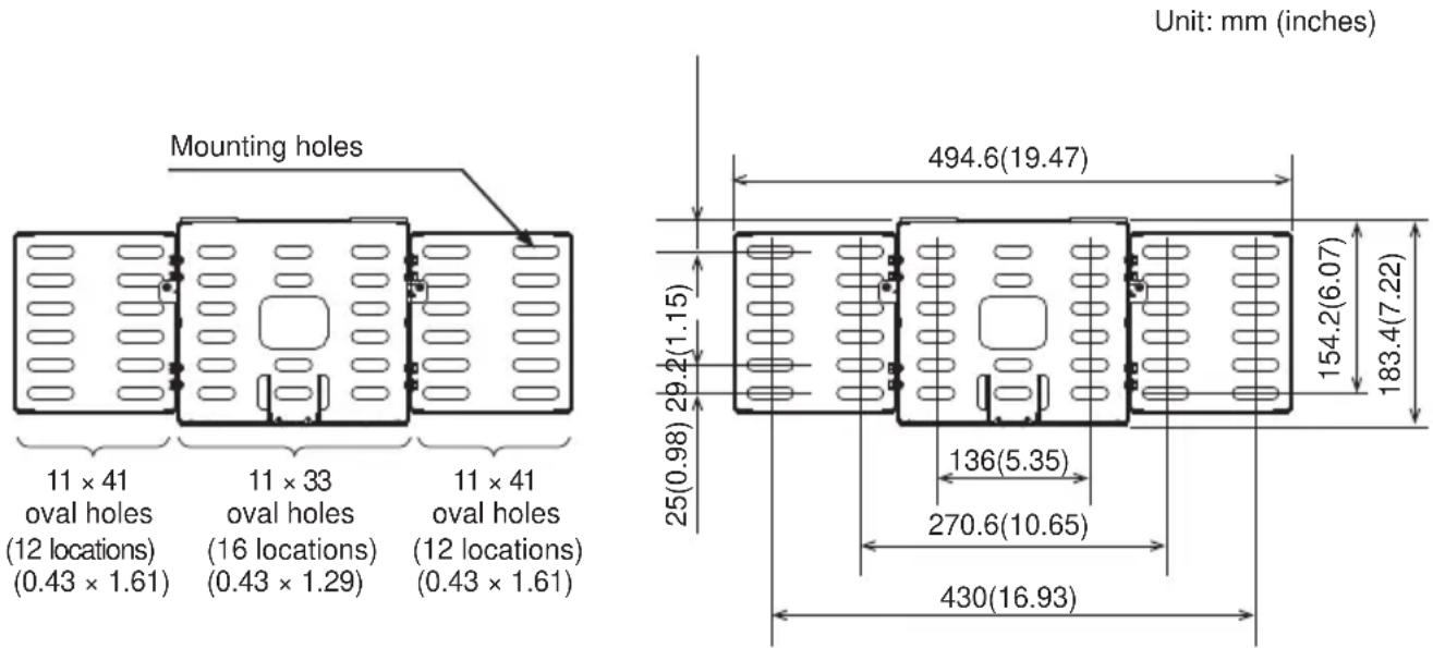
Tools needed for installation
- Have at least eight M8 anchor bolts on hand for attaching the wall-mount fixture to the wall. The fixture has 24 elongated 11mm × 41mm ( 0.43 × 1.61 -inch) holes and 16 elongated 11mm × 33mm ( 0.43 × 1.61 -inch) holes. The pull-out strength required of the bolts is at least 2,000N per bolt, so determine the appropriate length of bolts for the strength and thickness of the wall surface in order to meet this standard, and if necessary, increase the number of bolts.
WARNING
To the customer

- Do not attempt to install the projector yourself. Have your dealer or service center handle all installation work. Note that Hitachi will accept no liability whatsoever for accidents or injuries resulting from an incorrect installation or improper use.
■ Make sure that the projector is installed high enough so that there is no risk of people bumping their heads. If a sufficiently high installation cannot be made, be sure to take the necessary precautions when the projector is used.
■ Do not hang on the projector or the arm after installation as this could cause the projector to fall down or bend the arm resulting in injury or damage. - Do not install the projector in a location exposed to high humidity, dust or tobacco smoke or in a location exposed to smoke or steam.
■ Do not install the projector in a location exposed to vibrations.
■ After you have finished installation, keep this manual and accessories in a safe place for future reference.
■ Small parts could be swallowed by children and pets and should be kept out of their reach. If your child swallows any small parts, consult a doctor immediately.


To service personnel

■ Perform all installation work correctly according to this manual. Make sure that all specified screws and brackets are used in the installation.
■ Considerable care is required in planning and performing the installation so that it will support the weight of the projector and wall mount unit.
■ Never attempt to modify the wall mount unit. (We will not guarantee the strength of a unit that has been modified.)
■ Make sure that all screws are tightened to the proper torque after installation and adjustments. There must be no loose or over tightened screws.
■ Do not use adhesives, lubricants, lubricating oils or other chemicals designed to prevent loosening of fasteners on screws and bolts used to secure the projector ceiling mount. The use of such materials could cause the mount to fail and the projector to fall resulting in damage or injury.
■ Route electric cables as prescribed and take care not to damage them in the installation work.
- Be sure to read this manual and the User's Manual of the projector prior to installation to ensure that all safety instructions are observed and the projector is correctly installed.
■ Be sure to turn off the projector and disconnect the power plug from the wall outlet before starting installation work.


Routine Inspections
Like the projector, the wall mount unit should be inspected once a year.
- Check that the screws in the wall mount unit and adjusted parts are not loose.
- Check that the wall mount unit, adjusted parts and the set are not scarred or damaged.
Contents of this package
Check that the items listed in the table below are included in this package. If any are missing, please contact your dealer immediately. (The fasteners (screws, etc.) required for wall mounting are not supplied with the wall mount unit. Select fasteners that suit the structure of the wall to ensure they will properly support the projector and the wall mount unit.)
Part names in the figures on the following pages are indicated by the symbols given in the table below.
| Symbol | Part name | Quantity | Appearance | Symbol | Part name | Quantity | Appearance |
| A | Arm assembly | 1 | 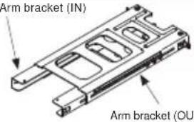 | K | M10 x 194mm Arm fixing strut screw | 2 | 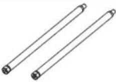 |
| B | Base bracket (center) | 1 | 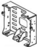 | L | M10 x 152mm Arm vertical adjustment screw | 1 | 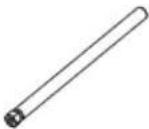 |
| C | Base bracket (sides) | 2 | 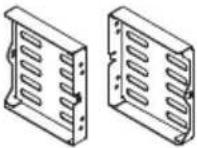 | M | Strut cover bracket | 2 | 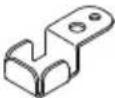 |
| D | Adjusting block | 1 | 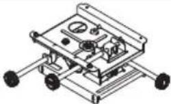 | N | M5 shoulder screw | 3 | 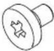 |
| E | Bracket | 1 | 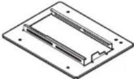 | O | Allen wrench | 1 | 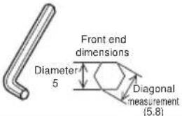 |
| F | Front cap | 1 | 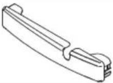 | P | Template sheet | 1 | 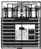 |
| G | Cable cover (middle) | 1 | 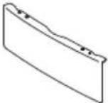 | Q | User's Manual (This book) | 1 | [W8SZ] |
| H | Cable cover (left) | 1 | 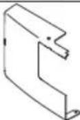 | R | M4 x 20mm cover mounting screws | 1 | 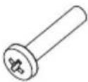 |
| I | Cable cover (right) | 1 S | Cable 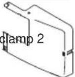 | 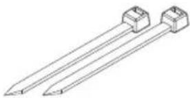 | |||
| J | M4 x 8 hexagon head screws | 17 | 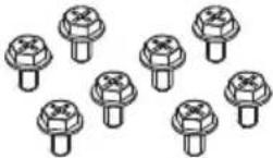 | T | M6 x 16 hexagon head screws | 4 |  |
Base bracket attachment diagram
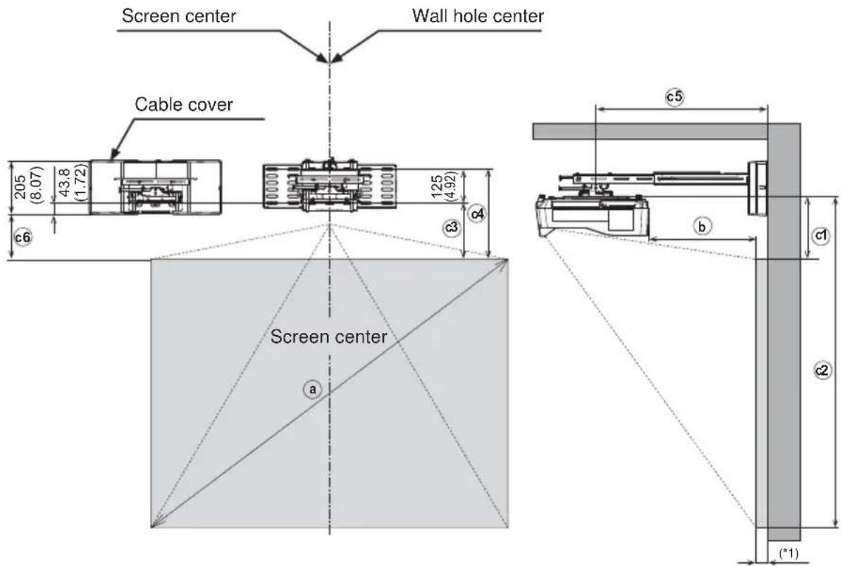
Screen thickness
Unit: mm (inches)
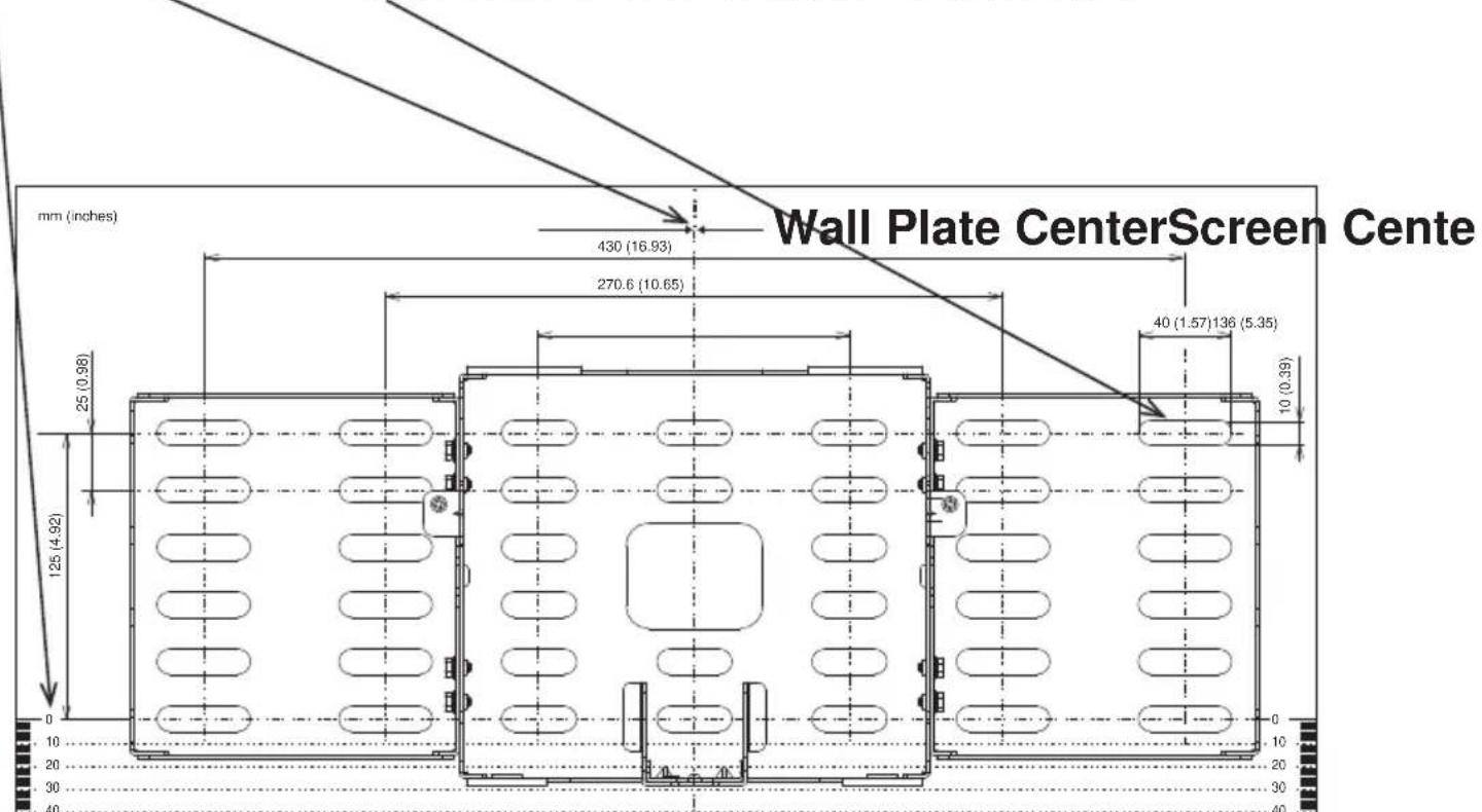
Sheet projecting distance table
16:10 screen (Full screen: Reference value for 1,280 × 800 pixel image.)
| a | b | c1 c2 c3 c4 c5 | ○ | ○ | ○ | c6 | |
| Diagonal size (inches) | mm (inches) | mm (inches) | mm (inches) | mm (inches) | mm (inches) | mm (inches) | mm (inches) |
| 70 149(5.9) | 254.1(10.0) | 196.1(47.1) | 226.2(8.9) | 351.2(13.8) | 398.7(15.7) | 182.4(7) | 2) |
| 80 219(8.6) | 278.1(10.9) | 355.1(53.4) | 250.2(9.8) | 375.2(14.8) | 468.7(18.5) | 206.4(8) | 1) |
| 90 289(11.4) | 302.1(11.9) | 1514.1(59.6) | 274.2(10.8) | 399.2(15.7) | 538.7(21.2) | 230.4(9.1) | |
| 100 359(14.1) | 327.1(12.9) | 1673.1(65.9) | 299.2(11.8) | 424.2(16.7) | 608.7(24.0) | 255.4(10.1) | |
| 110 429(16.9) | 352.1(13.9) | 1832.1(72.1) | 324.2(12.8) | 449.2(17.7) | 638.7(25.1) | 280.4(11.0) | |
4:3 screen (Full screen: Reference value for 1,024 × 768 pixel image.)
| a | b | c1 c2 c3 | c4 c5 | c6 | |||
| Diagonal size (inches) | mm (inches) | mm (inches) | mm (inches) | mm (inches) | mm (inches) | mm (inches) | mm (inches) |
| 70 | 118(4.6) | 244.1(9.6) | 1311.1(51.6) | 216.2(8.5) | 341.2(13.4) | 367.7(14.5) | 172.4(6.8) |
| 80 184(7.2) | 267.1(10.5) | 1486.1(58.5) | 239.2(9.4) | 364.2(14.3) | 433.7(17.1) | 195.4(7.7) | |
| 90 250(9.8) | 290.1(11.4) | 1662.1(65.4) | 262.2(10.3) | 387.2(15.2) | 499.7(19.7) | 218.4(8.6) | |
| 100 316(12.4) | 313.1(12.3) | 1837.1(72.3) | 285.2(11.2) | 410.2(16.1) | 565.7(22.3) | 241.4(9.5) | |
| 110 | 382(15.0) | 36.1(13.2) | 201.2(79.2) | 308.2(12.1) | 433.2(17.1) | 631.7(24.9) | 264.4(10.4) |
b Screen front from projector back c1 Screen top from bracket mounting surface c2 Screen bottom from bracket mounting surface c3 Screen top from bottom mounting hole on wall c4 Screen top from top mounting hole on wall c5 Bracket center from wall surface c6 Screen top from bottom of cable cover
(*1) For a screen thickness of 50mm, a maximum of up to 110 inches for XGA images and 100 inches for WXGA images can be projected.
For a screen thickness of 10mm, a maximum of up to 110 inches for WXGA images can be projected.
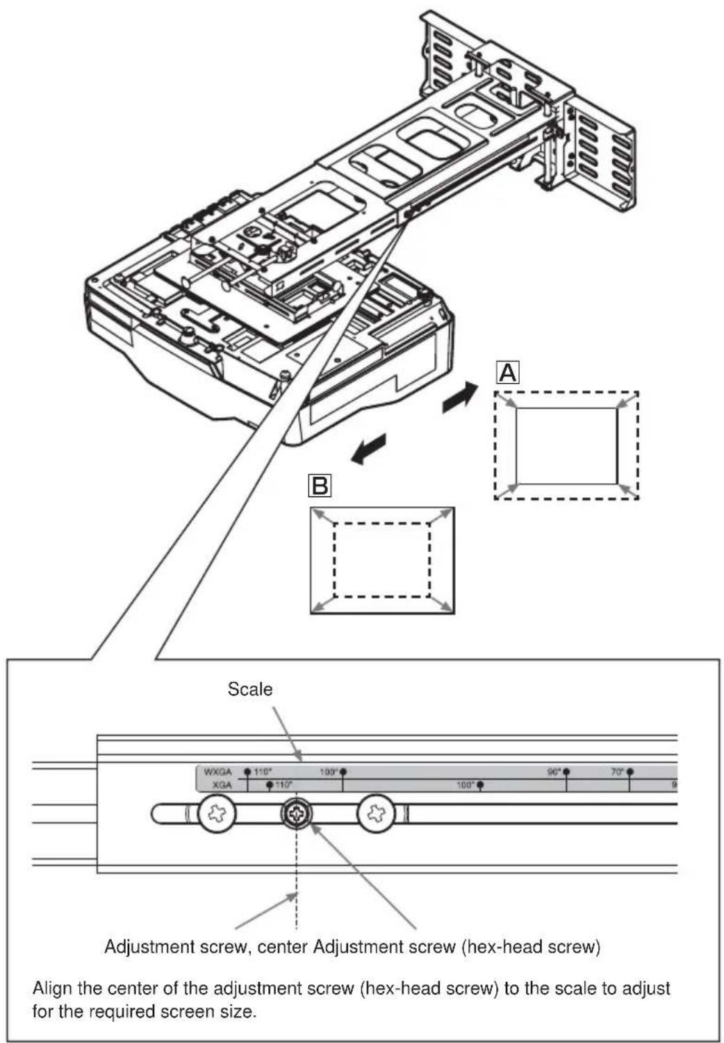
* Use of the supplied template sheet will facilitate positioning of the base bracket.
Note: Note that projection distance ⓑ will vary by ±3% depending on what product is used.
Template sheet usage
Determining location of wall holes
Place the template sheet (P) where you want to project the image.
① Vertical orientation: Align the top of the sheet with the upper edge of the image you want to project.
② Horizontal orientation: Align with the screen center.
③ Make a hole in the wall as indicated by the base bracket figure.
Template Sheet
Screen Center
Installation procedure
① Fasten the base bracket (center) (B) to the base brackets (side) (C) with the eight M4 x 8mm hex-head screws (J).
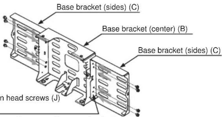
M4 × 8 hexagon head screws (J) (Eight places)
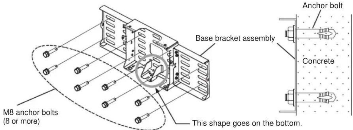
■ If mounting the base bracket assembly on a wall, use anchor bolts.
■ Use M8 anchor bolts.
■ Use anchor bolts of a length that suits the material, strength and thickness of the wall so that the pullout strength of each bolt meets or exceeds 2,000 N.
■ If the bolts cannot satisfy the required strength specifications, increase the number bolts.
■ When fastening the brackets with anchor bolts, use at least four bolts on the base bracket (center) (B) and at least two on each of the base brackets (side) (C) (for a total of at least 8 bolts).
- Base bracket (center) (B): at least 4 places
- Base brackets (side) (C): at least 2 places on each
WARNING
■ When attaching the wall mount unit to a wall covered with a layer of plaster or other weak finishing material, make sure the anchor bolts reach into the underlying concrete.
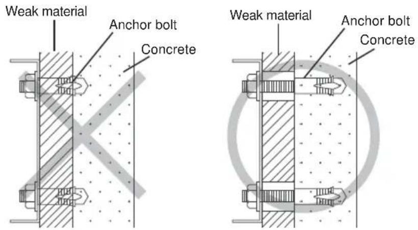
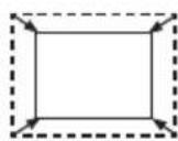
As shown in the figure, at least eight anchor bolts, two in each corner are required.
HAS-WM06
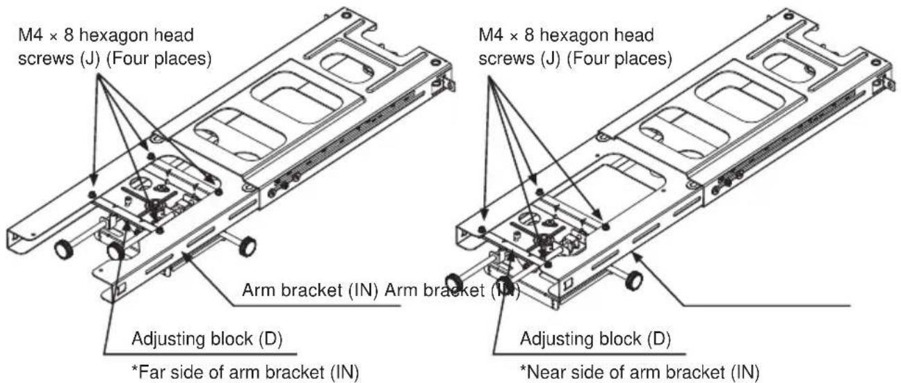
② Loosen the fastening screw (in the location indicated by the arrow in the diagram below) and extend the arm bracket (IN). Attach the adjustment block (D) to the arm bracket (IN).
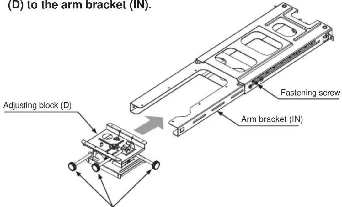
Note:
Face the knobs of the adjustment block (D) in the directions shown in this diagram.
③ Attach the adjustment block (D) to the arm bracket with four M4 x8mm hex-head screws (J). Align with the projection screen size and attach to the position as indicated in the diagram.
Tightening torque: 0.98 N·m (10 kgf·cm)
Projection screens 80 inches or larger Projection screens
than 80 inches.

CAUTION
■ Assemble the adjusting block (D) according to projection screen size.
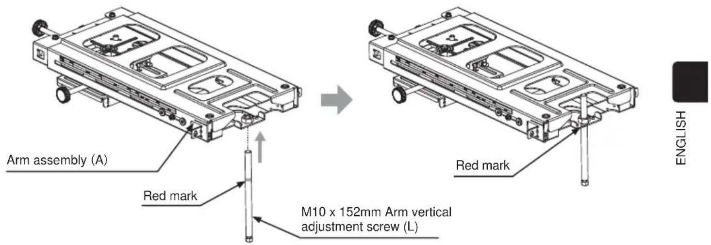
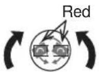
④ Attach the M10 x 162mm arm vertical adjustment screws (L) to the base bracket assembly (A) up to the red mark.
⑤ Mount the arm assembly (A) on the base bracket assembly.
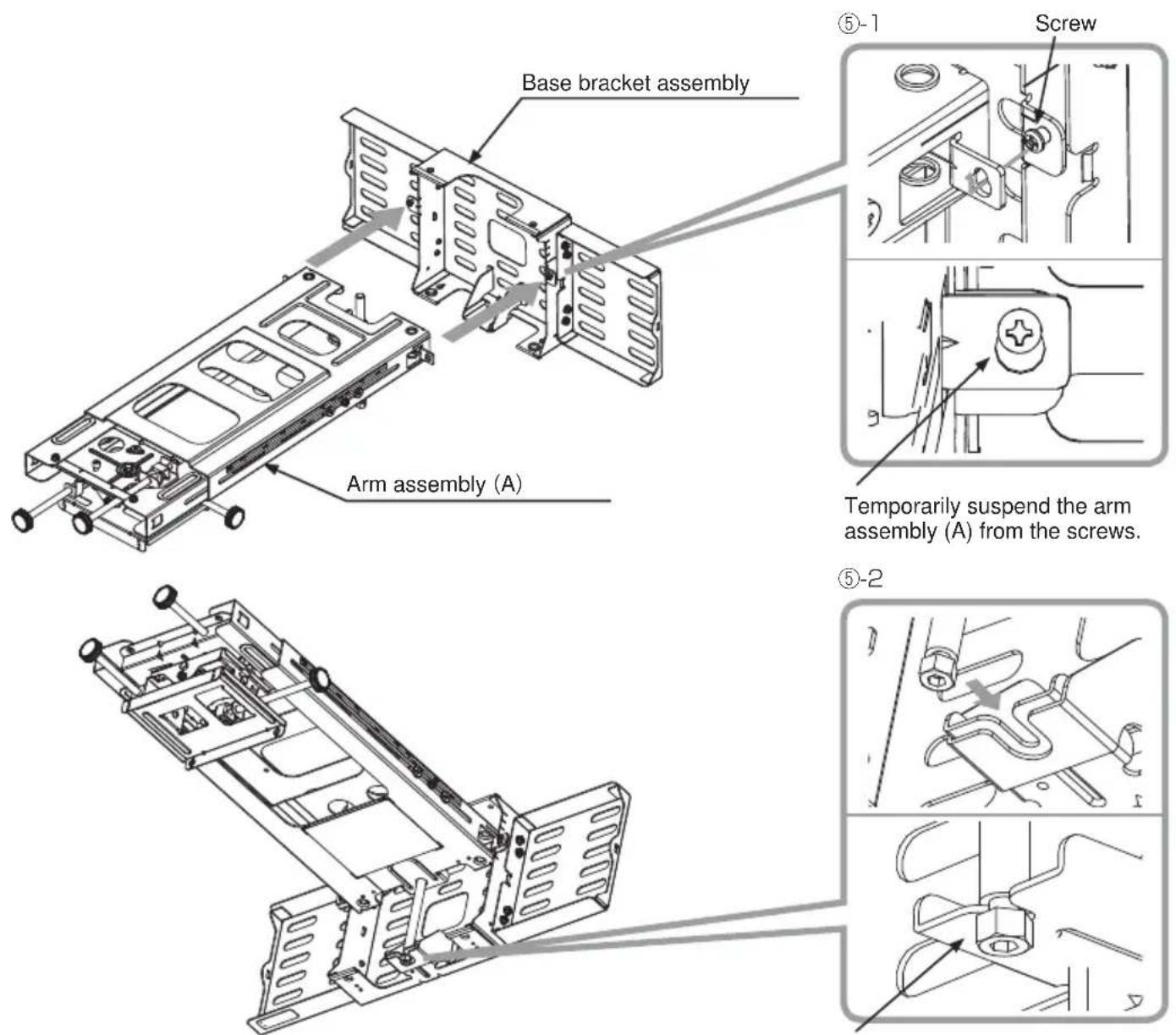
Hook the groove of the screw on the U-shape of the base bracket assembly.
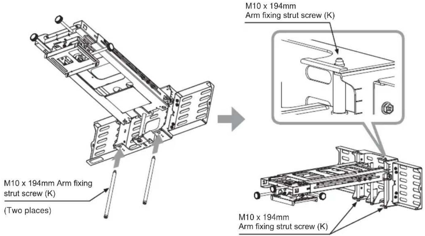
⑥ Pass the M10 x 194mm arm fixing strut screws (K) from under the base bracket (center) (B) and tighten them with a hex wrench (O) and fasten the arm assembly (A). (Two places)
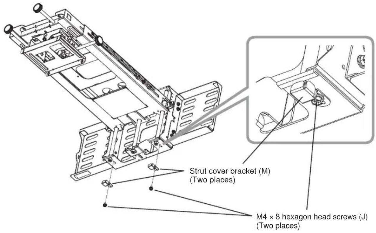
⑦ Fasten the strut cover bracket (M) with the M4 x 8mm hex-head screws (J). (Two places)
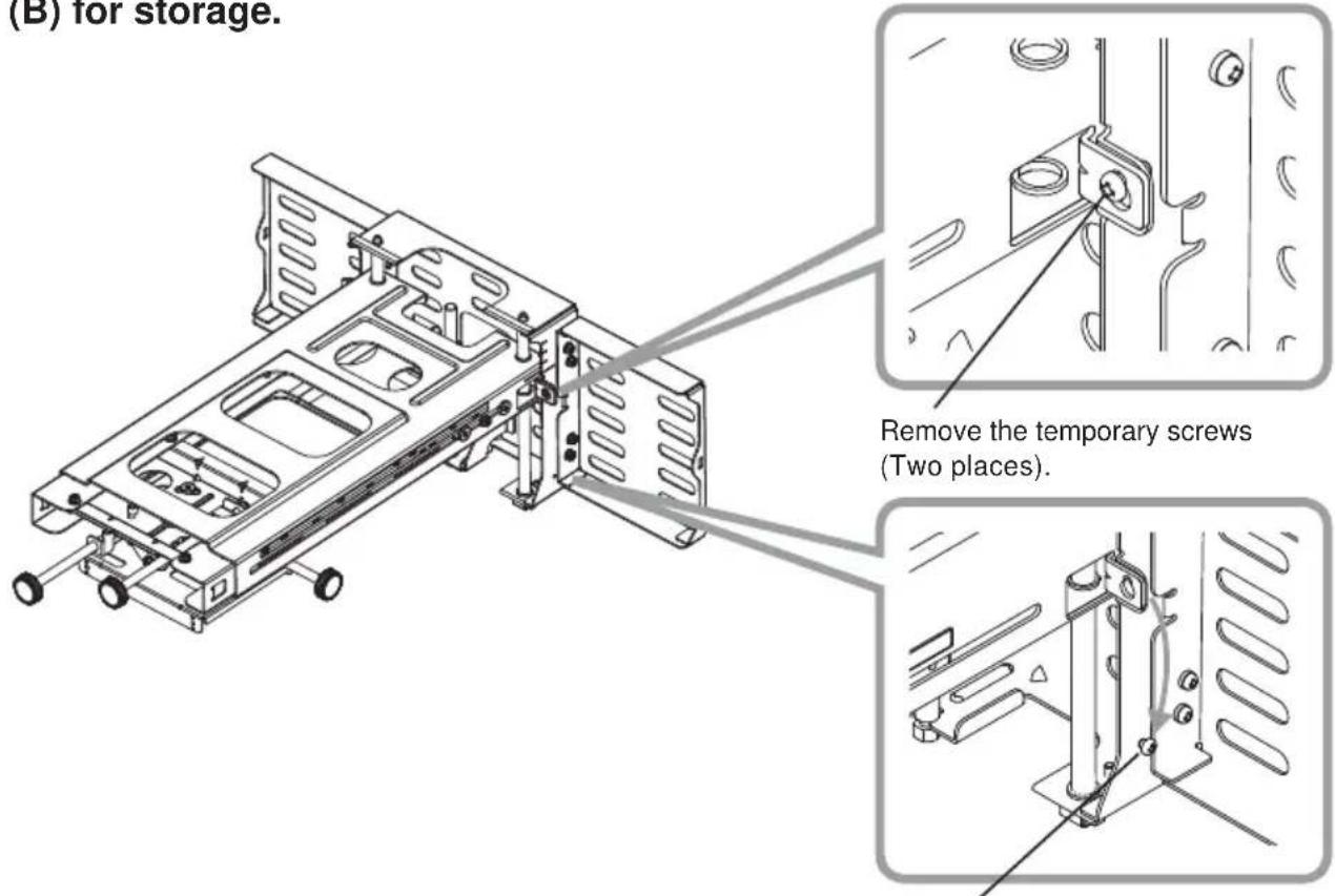
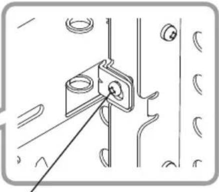
⑧ Remove the temporary mounting screws, and attach them to the base bracket (B) for storage.
natural_image
Technical line drawing of a mechanical bracket assembly with mounting holes and a connecting rod (no text or symbols)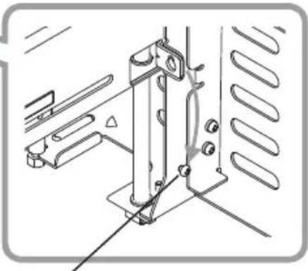
natural_image
Technical line drawing of a mechanical assembly with mounting brackets and a vertical support (no text or symbols)Attach to base bracket (B).
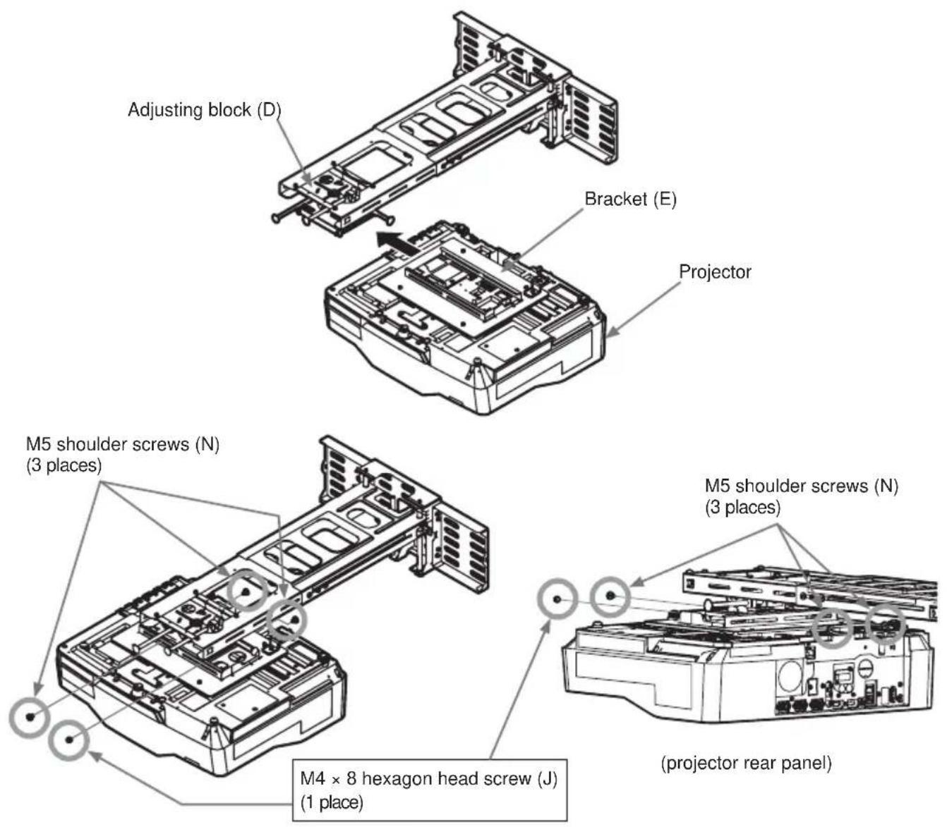
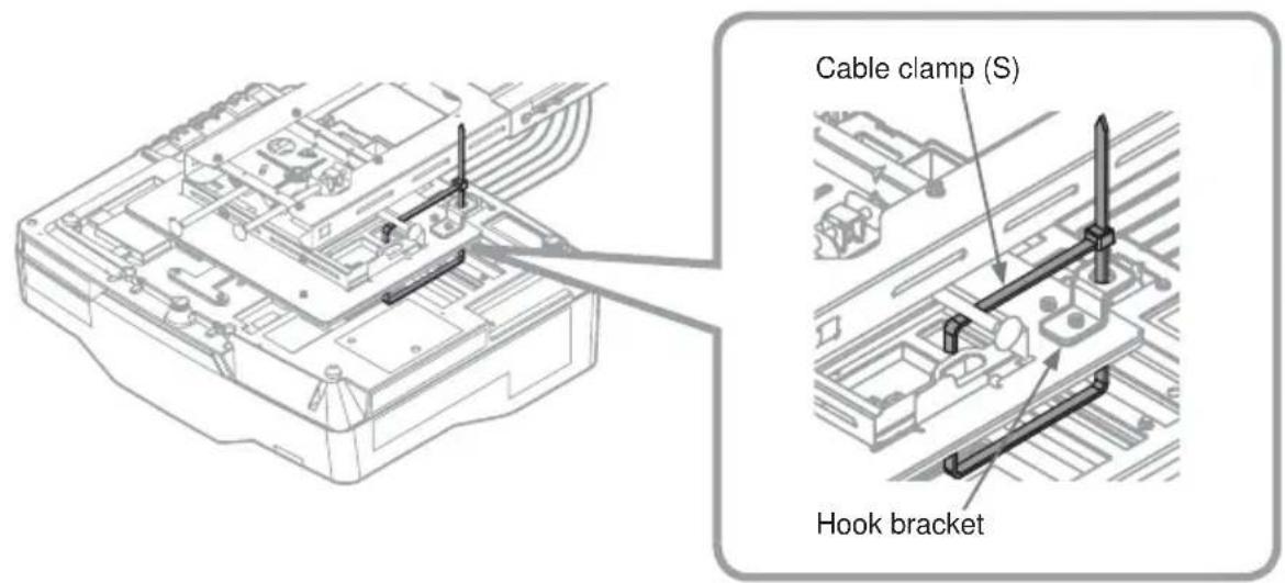
⑨ Attach the bracket (E) and the hook bracket enclosed with the projector to the projector using 5 M6 × 16 hex-head screws (T).
Tightening torque: 1.47 N·m (15 kgf·cm)
Note: Make sure that the bracket (E) is correctly oriented.
M6 × 16 hexagon head screws (T) (5 places)
Hook bracket
Bracket (E)
Take note of the orientation of this part.
Place cushioning material on a workbench. Turn over the projector and place it upside down on the cushioning material on the workbench.

WARNING
■ Never use screws other than those designated. Failure to heed this warning may cause the projector to fall or other hazard resulting in damage or injury.
HAS-WM06
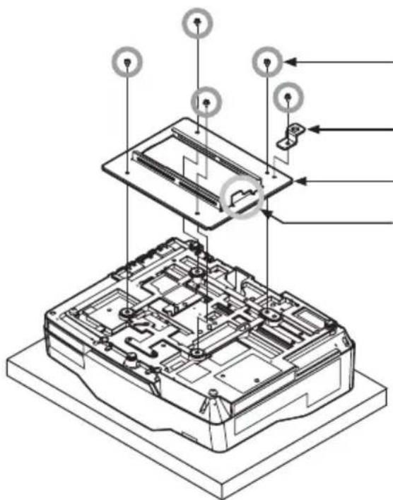
⑩ Mount bracket (E) from the direction of the arrow to the adjustment block (D).
Tighten the three M5 x 8mm shoulder screws (N) and 1 M4 x 8mm hex-head screw (J). Tightening torque: 0.98 N·m (10 kgf·cm)

WARNING
■ Never use screws other than those designated. Failure to heed this warning may cause the projector to fall or other hazard resulting in damage or injury.
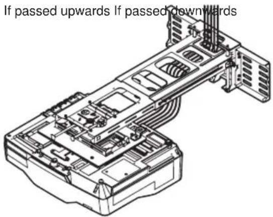
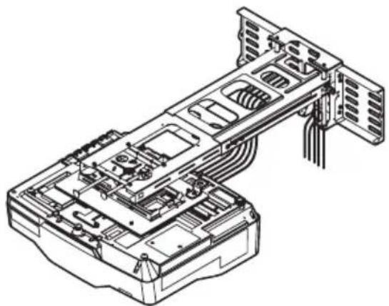
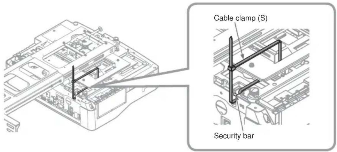
⑪ Connect the cables to the projector.
natural_image
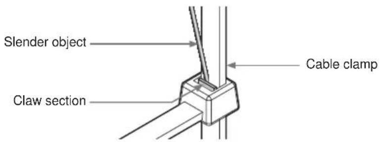
Technical line drawing of a server rack with internal components and ventilation ducts (no text or symbols)⑫ Installation and removal of the cable clamp (S)
To reuse the cable clamp, insert a slender object into the claw section as shown in the diagram to remove it.
⑬ Turn the projector on and project an image to make adjustments.
⑬-1. Project an image, adjust the image settings and focus on the projector.
- Adjust the focus.
- Select MIRROR.
- Set the D-ZOOM to its maximum value (full screen).
- Reset PERFECT FIT.
- Set the ⏰ KEYSTONE and ⬇ KEYSTONE values to 0.
* For details, see to the User's Manual for the projector.
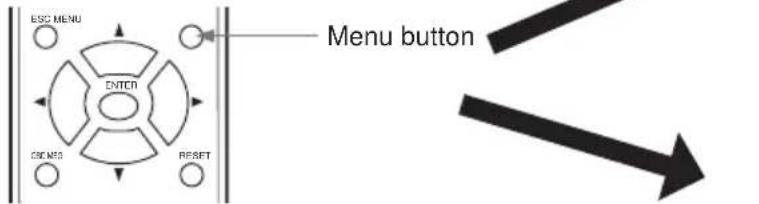
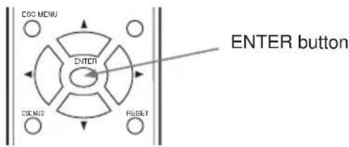
⑬-2. Use the remote control to select a screen for making adjustments.
① To simplify adjustments, press the Menu button on the remote control. The EASY MENU or ADVANCED MENU appears.
② Go to step ④ if the ADVANCED MENU appears.
③ If the EASY MENU appears, use the cursor buttons (▲/▼) to select the ADVANCED MENU.
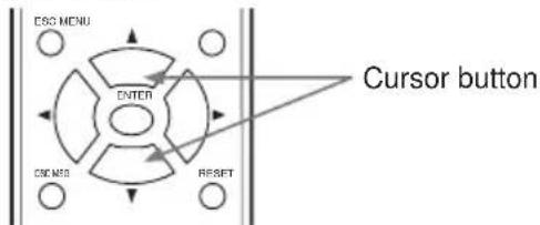
④ Use the cursor buttons (▲/▼) to select SCREEN.
⑤ Use the cursor buttons (▲/▼) to select WALL MOUNT in the illustrated template.
Press the ENTER button to display the selected WALL MOUNT.
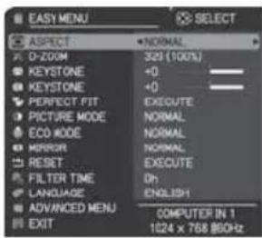
EASY MENU
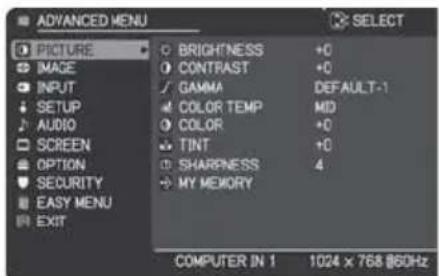
ADVANCED MENU
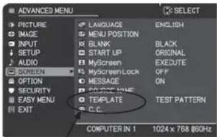
TEMPLATE
flowchart
graph TD
    A["Warning"] --> B["Display"]
    B --> C["Control Unit"]
    C --> D["Reset"]
    D --> E["Feedback Loop"]
    E --> F["Display"]
    style A fill:#f9f,stroke:#333
    style B fill:#ccf,stroke:#333
    style C fill:#cfc,stroke:#333
    style D fill:#fcc,stroke:#333
    style E fill:#cff,stroke:#333
    style F fill:#ffc,stroke:#333
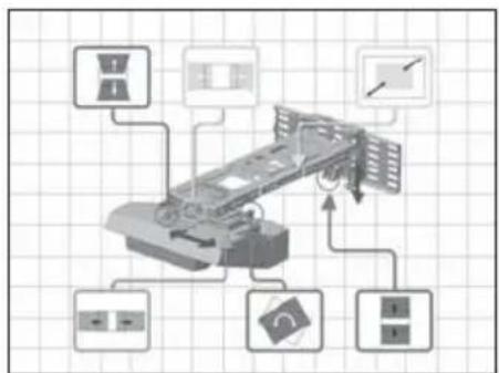
⑭ Adjust the image.
⑭ -1. Adjustment of image size.
- Slide the arm forward and backward to adjust image size.
HAS-WM06
⑭ -2. Make a rough focus adjustment.
For details, see the User's Manual for the projector.
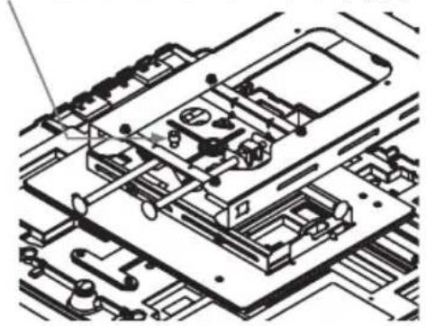
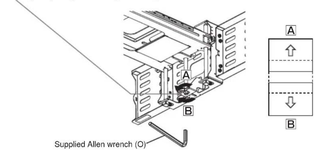
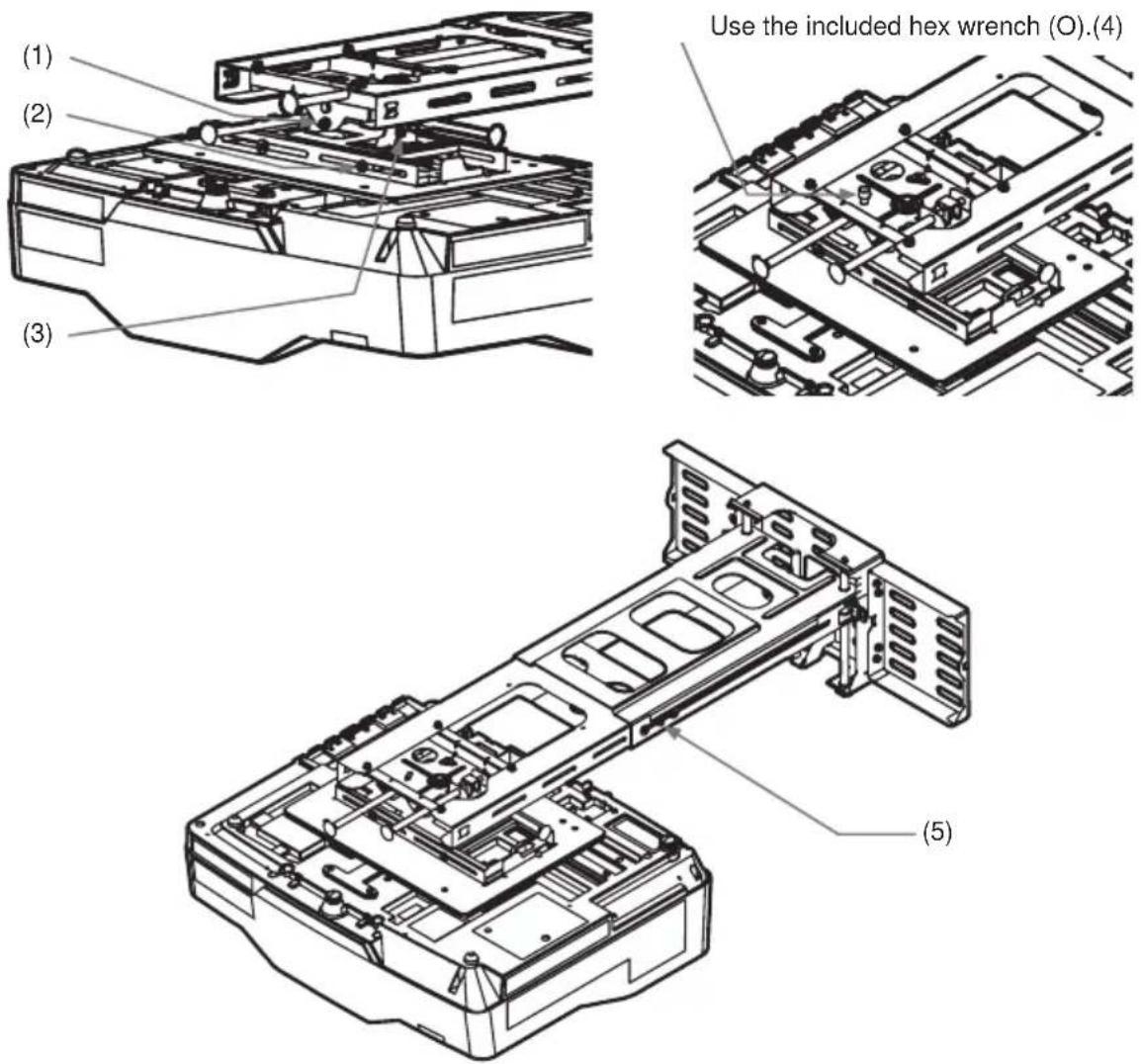
⑭ -3. Make fine adjustments.
Loosen fastening screws (1) to (4).
Follow the steps below to turn the adjusting screws and adjusting knobs to adjust the image.
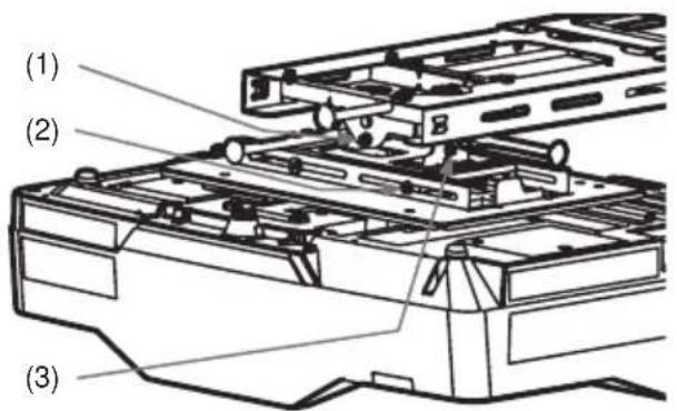
Use the included hex wrench (O).(4)
natural_image
Technical line drawing of an electronic device with internal components and circuitry (no text or symbols)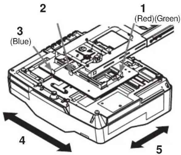
-
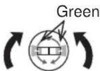
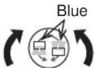
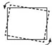
Fine adjustment of horizontal position
-
Fine adjustment of horizontal keystone
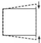
-
Fine adjustment of vertical keystone
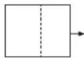
-
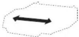
Fine adjustment of lateral position
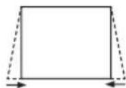
-
Fine adjustment of image size
- Fine adjustment of focus
For details, see the User's Manual for the projector.
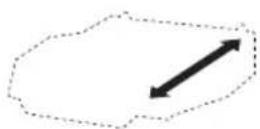
7. Fine adjustment of vertical position
Turn the height adjusting screw to adjust the height.
- Repeat steps 1 to 7 to fine adjust the image to the screen. See page 21 for details on adjustment range.
⑭ -4. Tighten the five loosened fastening screws (1) to (5).
Installing exterior parts
⑮ Procedure for installing exterior parts
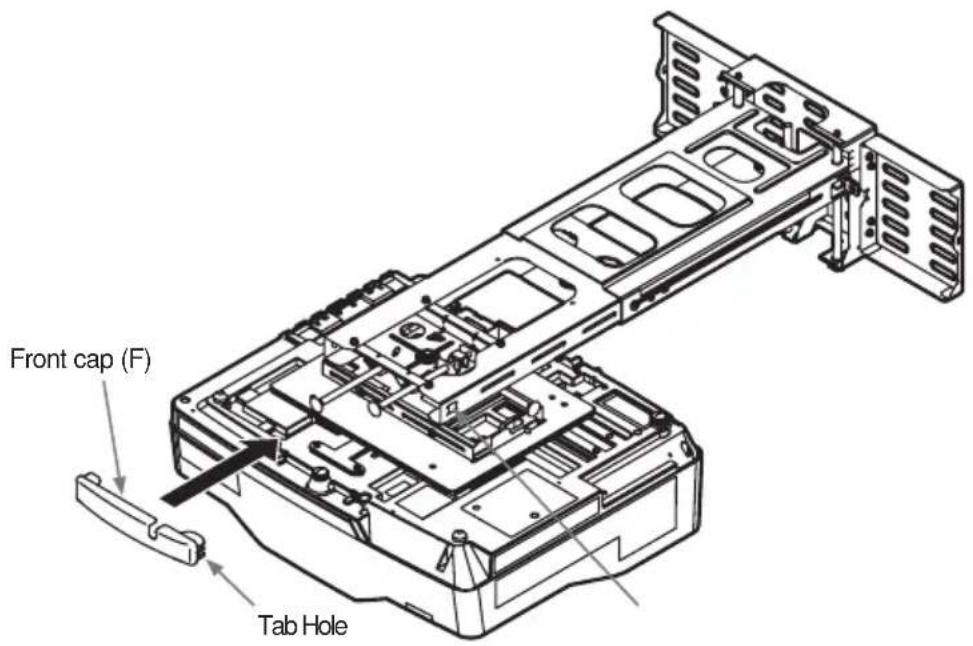
⑮-1. Attach the front cap (F) at the front end of the Arm bracket (IN).
Hook the tabs on either side in the holes in the arm bracket (IN).
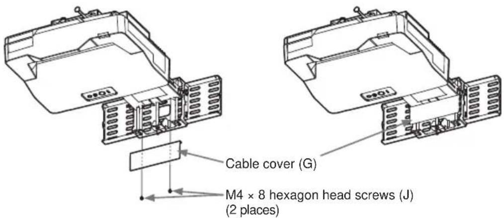
⑯ Attaching the cable cover
⑯-1. Fasten the cable cover (G) with the two M4 x 8mm hex-head screws (J).
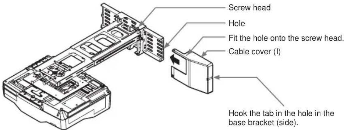
⑯-2. Attach cable cover (I) first.
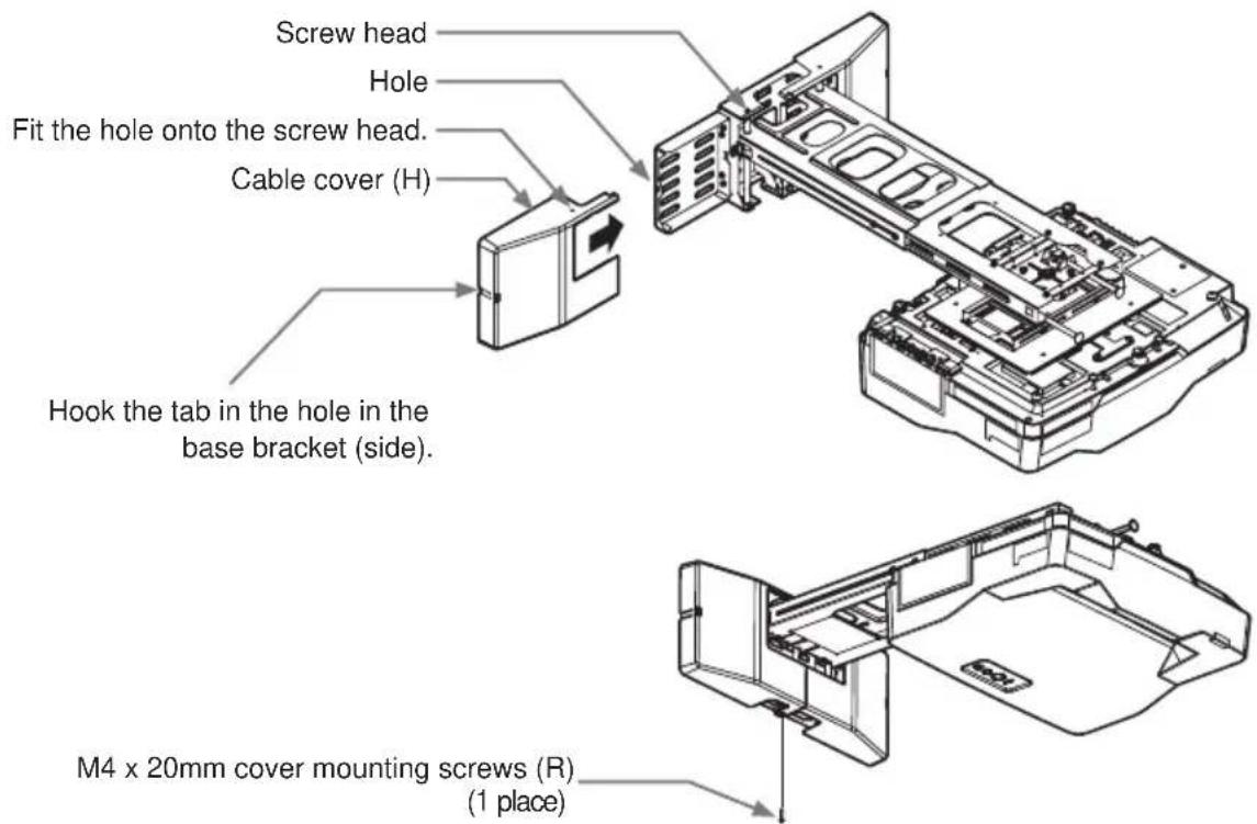
⑯-3. Attach cable cover (H) and fasten it with the one M4 x 20mm cover mounting screw (R).
Adjustment precautions
- Roll down screens and other screens that are not perfectly flat tend to substantially distort the projection surface and cannot be used. Use board screens or other flat screens.
Bead-type screens with a high screen gain are not suitable for this projector. Use of a matte screen with a wide viewing angle and a gain of about 1.0 is recommended.
Interaction between the screen pattern and LCD pixels may result in interference fringes (moiré). This is not a malfunction. Use a screen that suppresses this phenomenon. - The size of the image at the top of the screen changes with focus adjustment. Fine-tune screen position and angle after adjusting focus the first time.
- Reset corner fit before starting adjustments.
- Make sure that the digital zoom value is set to the maximum value (full screen) before starting adjustments.
• Make sure that the keystone control is set to 0 (no correction) before starting adjustments. - It takes about 30 minutes for lamp performance to stabilize and a change in environment may cause subtle changes in projection location and focus. Make proper adjustments to compensate for changes in focus.
Note:
- Changes in temperature, humidity and other ambient environmental factors may result in changes in screen size and location.
-
The minute vibrations and other phenomena that the wall mount unit and the mirror are exposed to will start to cause changes in projection location a week or so after installation.
-
• Set a screen size that is smaller relative to actual screen size to allow for changes after installation.
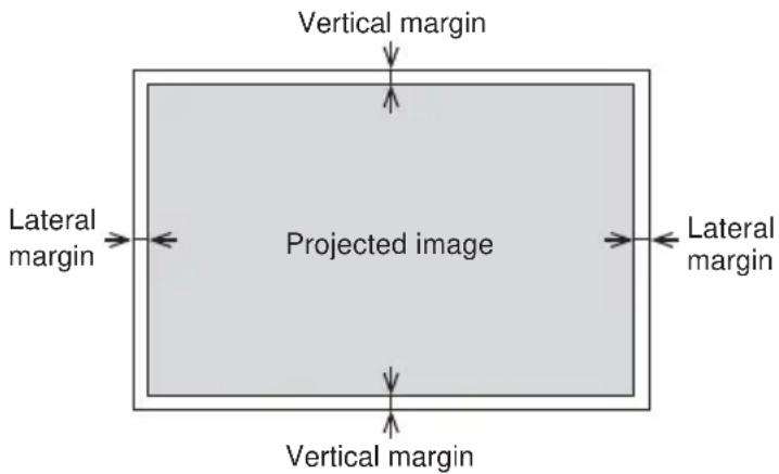
- Use the values in the table below to set a vertical and lateral margin.
- Set a margin for each corner to allow for screen distortion.
(both 4:3 and 16:10 screens)
| Screen sizeDiagonal size(inches) | Vertical margin(mm) | Lateral margin(mm) |
| 60 20 25 | ||
| 80 25 30 | ||
| 100 30 35 | ||
| 110 32 . | 5 37. 5 |
Adjustment specifications
| Item Image movement | Fine adjustment amount (amount of projector movement) | Description of adjustment method | |
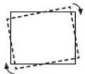
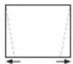
| Fine adjustment of horizontal position | 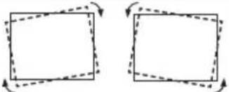 | ±5° page 15 | |
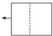
| Fine adjustment of horizontal keystone | 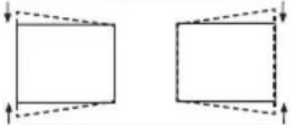 | ±5° page 15 | |
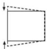
| Fine adjustment of vertical keystone | 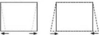 | ±5° page 15 | |
| Fine adjustment of lateral position | 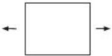 | ±50 mm (1.96 inches) page 15 | |
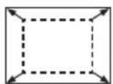
| Fine adjustment of image size | 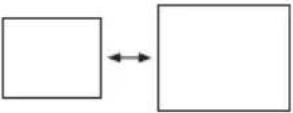 | 308 mm (12.1 inches) page 15 | |
| Fine adjustment of vertical position | 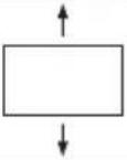 | ±35 mm (1.37 inches) page 16 | |
Applicable models
Supported Hitachi projector models
| Model Screen size Weight | |||
| Projector model A LP- | AW4001 | 16:10 | Approx. 7.6kg |
| LP-AW3001 | Approx. 7.4kg | ||
| LP-AX3001 | 4:3 Approx. 7.4kg | ||
| Wall mount unit HAS-W | WM06 Approx. 7.1kg | ||
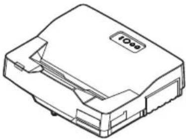
natural_image
Line drawing of a device with a label 'IOO' on the top surface (no other text or symbols)- Disclaimer
- Safety Symbols
- WARNING
- CAUTION
- Installation Precautions
- Be sure to observe the following instructions when installing an projector.
- Tools needed for installation
- To the customer
- To service personnel
- Routine Inspections
- Contents of this package
- Base bracket attachment diagram
- Sheet projecting distance table
- Template sheet usage
- Determining location of wall holes
- Installation procedure
- HAS-WM06
- ⑩ Mount bracket (E) from the direction of the arrow to the adjustment block (D).
- ⑪ Connect the cables to the projector.
- ⑫ Installation and removal of the cable clamp (S)
- ⑭ Adjust the image.
- ⑭ -1. Adjustment of image size.
- Fine adjustment of vertical position
- ⑭ -4. Tighten the five loosened fastening screws (1) to (5).
- Installing exterior parts
- ⑮ Procedure for installing exterior parts
- ⑯ Attaching the cable cover
- Adjustment precautions
- Note:
- Applicable models
Brand : HITACHI
Model : HAS-WM06
Category : Wall mount