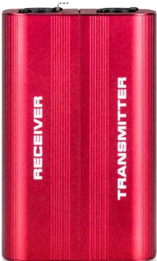
SPT-3rt - Uncategorized UNiKA - Free user manual and instructions
Find the device manual for free SPT-3rt UNiKA in PDF.


User questions about SPT-3rt UNiKA
0 question about this device. Answer the ones you know or ask your own.
Ask a new question about this device
Download the instructions for your Uncategorized in PDF format for free! Find your manual SPT-3rt - UNiKA and take your electronic device back in hand. On this page are published all the documents necessary for the use of your device. SPT-3rt by UNiKA.
USER MANUAL SPT-3rt UNiKA
Functions Instruction
Operation Guidance
Notes
Specification
Overview
SPT-3rt is the best tools of UNiKA Stage Series. This tool is suitable for any speaker manufacturer, touring and fixed installation applications. It can be used for testing phase either speaker or balance cable. An external microphone input socket can be connected external dynamic microphone to test the speakers that have been hung up. By using neodymium magnet to combine transmitter and receiver units for easy carrying.
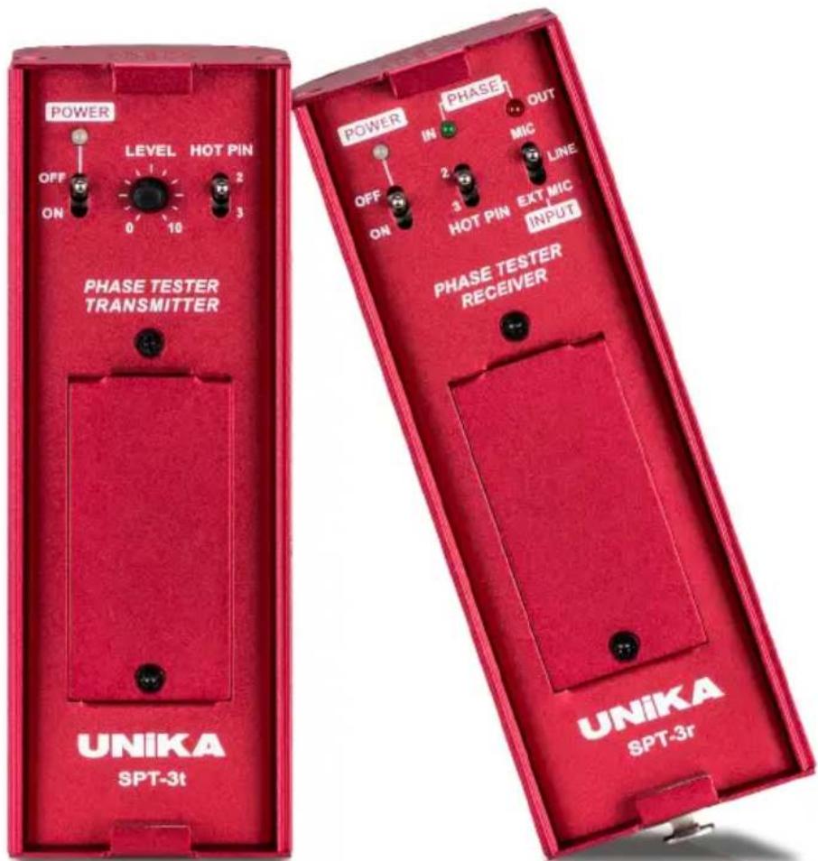
text_image
POWER OFF ON LEVEL HOT PIN 0 10 3 PHASE TESTER TRANSMITTER POWER IN PHASE OUT OFF ON MIC 2 3 HOT PIN EXT MIC INPUT PHASE TESTER RECEIVER UNIKA SPT-3t UNIKA SPT-3rFeatures
- Detect the phase accuracy in any audio system, prevent the musical signal from cancellation due to the opposite phase.
- Detect the XLR signal cable to prevent it from contact fail, brokerage or opposite connection.
- Built-in external microphone input socket in order to use for the harder environment such as the hanging speaker cluster.
- Testable range from 10 cm to 3 meters. Some ideal environment can be tested far away from the axis of speaker for 7 meters.
Functions Instruction

natural_image
Diagram of a device with a central dot array and four surrounding circular components, labeled with number 1 (no text or symbols beyond label)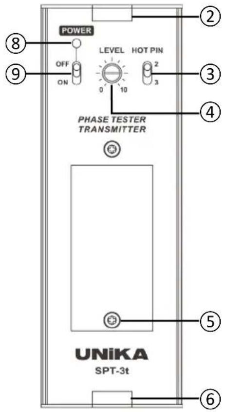
text_image
POWER OFF ON LEVEL HOT PIN 0 10 2 3 4 PHASE TESTER TRANSMITTER UNiKA SPT-3t ② ③ ④ ⑤ ⑥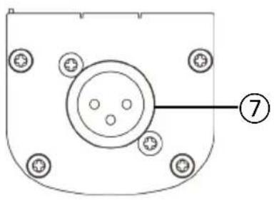
natural_image
Pure diagram of a mechanical component with no text, numbers, or symbolsSPT-3t Transmitter
① Buzzer to generate pulse tone.
② Neodymium magnet to combine SPT-3r receiver.
③ HOT PIN selector, select test pin of XLR cable either pin-2 or pin-3.
④ Linear pot to tune pulse tone level.
⑤ Release screw to open battery cabinet. Recommend to use 9V PP3 Alkaline battery.
⑥ Neodymium magnet to combine SPT-3r receiver.
⑦ Male XLR connector to connect balance cable to send pulse tone to mixer.
⑧ Power and pulse tone indicator.
⑨ Power switch.
Functions Instruction
text_image
① ② ③ ④ ⑤ ⑥ ⑦ ⑧ ⑨ ⑩ ⑪ POWER IN PHASE OUT OFF ON MIC HOT PIN EXT MIC INPUT PHASE TESTER RECEIVER UNiKA SPT-3r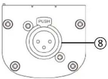
text_image
PUSH ⑧SPT-3r Receiver
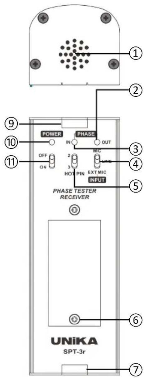
① Omni direction microphone.
② Red color out phase indicator.
③ Green color in phase indicator.
④ Input selector, select test sources and applications from built-in Mic/Cable test/EXT MIC etc.
⑤ HOT PIN selector, select test pin of XLR cable either pin-2 or pin-3.
⑥ Release screw to open battery cabinet. Recommend to use 9V PP3 Alkaline battery.
⑦ Neodymium magnet to combine SPT-3t transmitter.
⑧ Female XLR connector to connect external dynamic microphone.
⑨ Neodymium magnet to combine SPT-3t transmitter.
⑩ Blue color power indicator.
⑪ Power switch.
Operational Guidance
- Phase tester - Test XLR cable
flowchart
graph TD
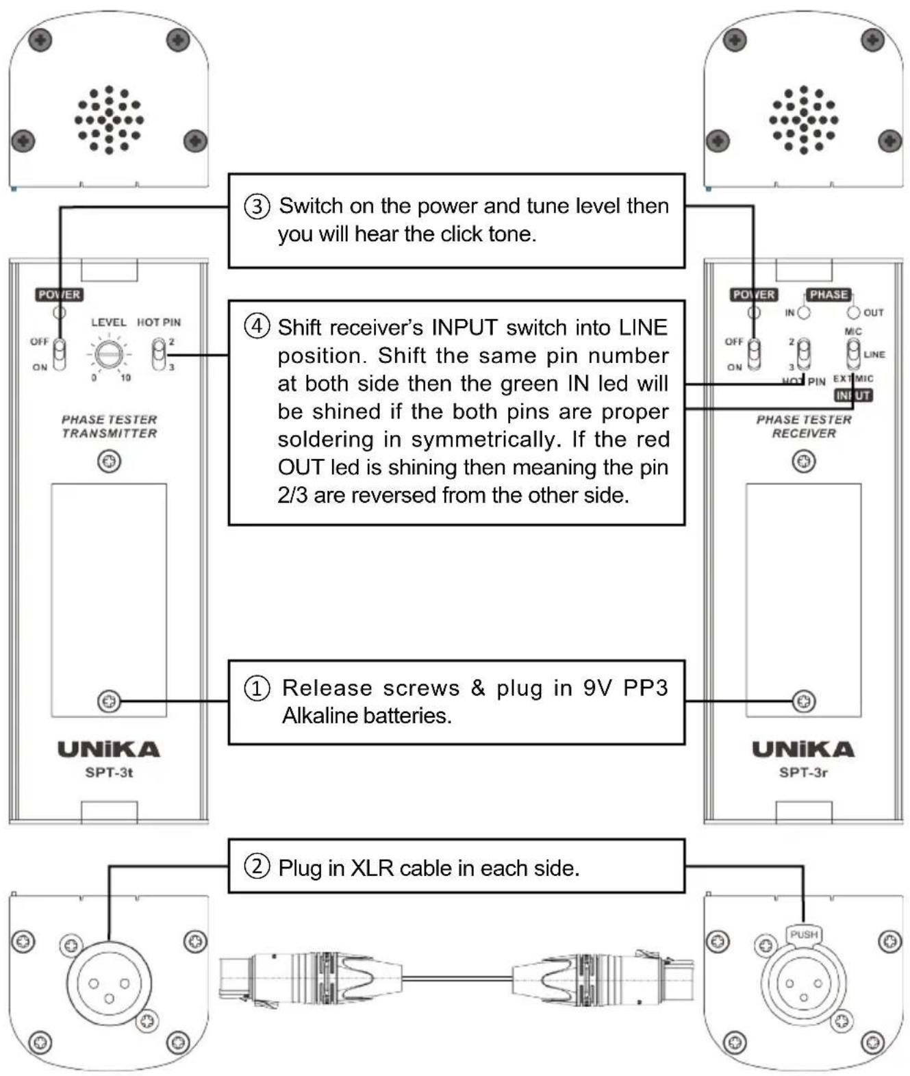
    A["① Release screws & plug in 9V PP3 Alkaline batteries."] --> B["② Plug in XLR cable in each side."]
    B --> C["③ Switch on the power and tune level then you will hear the click tone."]
    C --> D["④ Shift receiver's INPUT switch into LINE position. Shift the same pin number at both side then the green IN led will be shined if the both pins are proper soldering in symmetrically. If the red OUT led is shining then meaning the pin 2/3 are reversed from the other side."]
    D --> E["⑤ PHASE TESTER TRANSMITTER"]
    E --> F["POWER OFF ON LEVEL HOT PIN 0 10 2 3"]
    F --> G["UNiKA SPT-3t"]
    G --> H["UNiKA SPT-3r"]
- Test speaker's phase by built-in MIC

flowchart
graph TD
    A["⑤ Aiming receiver's built-in mic to axis position of speaker from 1 meter or more distance. If the green IN led is shined then the phase of speaker is proper. If the red OUT led is shined then the phase of speaker is reversed."] --> B["③ Switch on the power and tune level then you will hear the click tone."]
    B --> C["④ Shift the receiver's input switch into MIC position. And adjust transmitter's LEVEL. You can hear click tone from speaker."]
    C --> D["① Release screws & plug in 9V PP3 Alkaline batteries."]
    C --> E["② Plug female side of XLR connector into transmitter and plug male side of XLR connector into mixer or amplifier."]
Operational Guidance
- Test speaker's phase by EXT. MIC
text_image
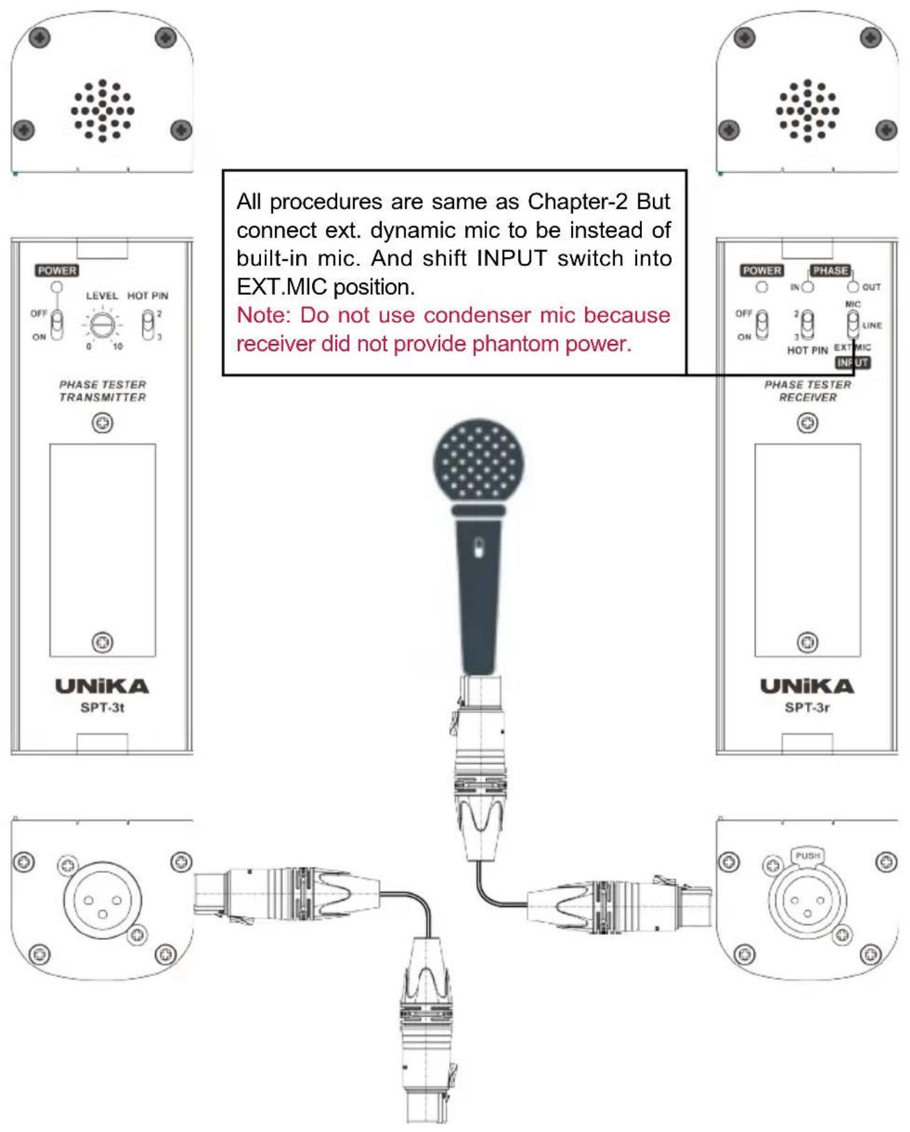
All procedures are same as Chapter-2 But connect ext. dynamic mic to be instead of built-in mic. And shift INPUT switch into EXT.MIC position. Note: Do not use condenser mic because receiver did not provide phantom power. POWER OFF ON LEVEL HOT PIN 2 0 10 PHASE TESTER TRANSMITTER UNiKA SPT-3t POWER IN OFF ON PHASE OUT MIC HOT PIN EXT MIC INPUT PHASE TESTER RECEIVER UNiKA SPT-3r PUSHNotes
- Avoid direct sun light and damp working environment.
- The unit is designed to operate between 0^55^ ( 32^122^ ) and in an atmosphere of relative humidity up to 80%.
- Recommend to use 9V PP3 Alkaline battery.
info@unikapro.com
If you still need further clarification, please send email to us and we will do our very best to reply you in short order.
Specification
The following information is subject to change without notice.
| TRANSMITTER | |
| Signal type | Pulse tone from buzzer |
| Frequency spectrum, electrical | 1Hz to 20KHz |
| Frequency spectrum, acoustic | 200Hz to 5KHz |
| Output level, electrical | 0 to 1V (Acoustic level is fixed) |
| Output load impedance | >1KΩ |
| Output source impedance | 1KΩ |
| Power supply | 9V PP3 Alkaline battery (approx. 50 hours) |
| Power consumption | 10mA |
| RECEIVER | |
| Frequency spectrum, electrical | 1Hz to 20KHz |
| Frequency spectrum, acoustic | 10Hz to 1KHz |
| Input impedance (Mic) | 1KΩ |
| Input impedance (Line) | 10KΩ |
| Input level (Mic) | 10mV - 1V |
| Input level (Line) | 0.5V to 50V |
| Output level | 0V to 1V |
| Power supply | 9V PP3 Alkaline battery (approx. 50 hours) |
| Power consumption | 10mA |
| PHYSICAL CHARACTERISTICS (whole set) | |
| Dimensions/Shipping dimensions (W x D x H) | 120 X 95 X 56 mm |
| 20pcs packs dimensions (W x D x H) | 245 X 195 X 117 mm |
| Weight/Shipping weight | 0.4 Kg / 0.45kg |
| 20pcs packs shipping weight | 10.0 Kg |
| Operating temperature | 0°~50°C |
| Storage temperature | -30°~+75°C |