
FC 56 C - Brush cutter STIHL - Free user manual and instructions
Find the device manual for free FC 56 C STIHL in PDF.


| Product Type | Brush Cutter (Edger) |
| Brand | STIHL |
| Model | FC 56 C |
| Engine Displacement | 27.2 cc (1.66 cu in) |
| Engine Power | 1.1 bhp (0.8 kW) at 8,500 rpm |
| Fuel Type | Unleaded gasoline mixed with STIHL two-stroke oil (50:1 ratio) |
| Fuel Tank Capacity | 11.5 fl oz (0.34 l) |
| Weight (dry, with deflector and blade) | 13.4 lbs (6.1 kg) |
| Cutting Blade Length | 200 mm (7.9 in) |
| Blade Thickness | 2.4 mm or 3.8 mm |
| Max. Output Shaft Speed (cutting blade) | 8,600 rpm |
| Idle Speed | 2,800 rpm |
| Cut-off Speed (rated) | 10,000 rpm |
| Spark Plug (resistor type) | NGK CMR 6 H |
| Electrode Gap | 0.5 mm (0.02 in) |
| Igntion System | Electronic magneto ignition |
| Fuel System | All-position diaphragm carburetor with integral fuel pump |
| Handle Type | Adjustable loop handle |
| Depth of Cut Adjustment | Wheel with wingnut, max 5 mm soil break |
| Safety Features | Throttle trigger lockout, stop switch, deflector, wear guard |
| Maintenance Interval (spark plug replacement) | Every 100 operating hours |
| Emission Compliance | EPA and CARB certified |
| Warranty | 2 years (emission-related parts) |
Frequently Asked Questions - FC 56 C STIHL
User questions about FC 56 C STIHL
0 question about this device. Answer the ones you know or ask your own.
Ask a new question about this device
Download the instructions for your Brush cutter in PDF format for free! Find your manual FC 56 C - STIHL and take your electronic device back in hand. On this page are published all the documents necessary for the use of your device. FC 56 C by STIHL.
USER MANUAL FC 56 C STIHL
natural_image
Close-up of a manual push-button shaver tool with metal blade and black handle (no visible text or symbols)WARNING
Read Instruction Manual thoroughly before use and follow all safety precautions – improper use can cause serious or fatal injury.
ADVERTENCIA
natural_image
Two black-and-white icons: a triangular warning triangle with an exclamation mark and a person reading a book (no text or symbols present)Instruction Manual
1 - 39
Guide to Using this Manual 2
Safety Precautions and Working Techniques 3
Using the Unit 13
Mounting the Loop Handle 15
Mounting the Cutting Blade 16
Fuel 17
Fueling 18
Starting / Stopping the Engine 20
Operating Instructions 22
Cleaning the Air Filter 22
Engine Management 23
Adjusting the Carburetor 23
Spark Plug 24
Engine Running Behavior 25
Storing the Machine 25
Replacing the Depth Wheel 26
Replacing the Skirt 26
Replacing the Cutting Blade 27
Checking and Replacing the Wear
Guard 27
Inspections and Maintenance by
Dealer 28
Maintenance and Care 29
Main Parts 31
Specifications 33
Maintenance and Repairs 33
Disposal 34
Limited Warranty 34
STIHL Incorporated Federal
Emission Control Warranty
Statement 34

FC 56 C
STIHL Incorporated California
Exhaust and Evaporative
Emissions Control Warranty
Statement 36
Trademarks
38
Allow only persons who fully understand this manual to operate your edger.
To receive maximum performance and satisfaction from your STIHL edger, it is important that you read, understand and follow the safety precautions and the operating and maintenance instructions in chapter "Safety Precautions and Working Techniques" before using your edger. For further information you can go to www.stihlusa.com.
Contact your STIHL dealer or the STIHL distributor for your area if you do not understand any of the instructions in this manual.

WARNING
Because an edger is a high-speed cutting tool some special safety precautions must be observed to reduce the risk of personal injury. Careless or improper use may cause serious or even fatal injury.
Make sure your unit is equipped with the proper deflector and handle for the type of cutting attachment being used.
Always wear proper eye protection.
This instruction manual is protected by copyright. All rights reserved, especially the rights to reproduce, translate and process with electronic systems.
English
Guide to Using this Manual
Pictograms
The meanings of the pictograms attached to or embossed on the machine are explained in this manual.
Depending on the model concerned, the following pictograms may be on your machine.

Fuel tank for gasoline and engine oil mixture

Press to operate decom- pression valve

Manual fuel pump

Press to operate manual fuel pump

Filler hole for gear lubricant

Air intake summer mode

Air intake winter mode

Handle heating
Symbols in Text
Many operating and safety instructions are supported by illustrations.
The individual steps or procedures described in the manual may be shown in different ways:
● A bullet indicates a step or procedure.
A description of a step or procedure that refers directly to an illustration may contain item numbers that appear in the illustration. For example:
- Remove the screw (1)
● Pull the spark arresting screen (2) upwards out of the muffler
In addition to the operating instructions, this manual may contain paragraphs that require your special attention. Such paragraphs are indicated with the symbols and signal words described below:

Indicates a hazardous situation that, if not avoided, will result in death or serious injury.

Indicates a hazardous situation that, if not avoided, could result in death or serious injury.
NOTICE
Indicates a risk of property damage, including damage to the machine or its individual components.
Engineering Improvements
STIHL's philosophy is to continually improve all of its products. As a result, engineering changes and improvements are made from time to time. Therefore, some changes, modifications and improvements may not be covered in this manual. If the operating characteristics or the appearance of your machine differs from those described in this manual, please contact your STIHL dealer or the STIHL distributor for your area for assistance.
Safety Precautions and Working Techniques

Because an edger is a high-speed, fast-cutting power tool, special safety precautions must be observed to reduce the risk of personal injury.

It is important that you read, fully understand and observe the following safety precautions and warnings. Read the instruction manual and the safety precautions periodically. Careless or improper use may cause serious or fatal injury.
WARNING
As more fully explained later in these Safety Precautions, to reduce the risk of personal injury, make sure your unit is equipped with the proper handle, harness and deflector. Use only cutting attachments that are specifically authorized by STIHL for use on your FC model.
Have your STIHL dealer show you how to operate your power tool. Observe all applicable local safety regulations, standards and ordinances.
WARNING
Do not lend or rent your power tool without the instruction manual. Be sure that anyone using it understands the information contained in this manual.
WARNING
The use of this machine may be hazardous. If the rotating blade comes in contact with your body, it will cut you. When it comes in contact with solid foreign objects such as rocks or bits of metal, it may fling them directly or by ricochet in the direction of bystanders or the operator. Striking such objects could damage the cutting attachment and may cause blades to crack, chip or break. Thrown objects, including broken blades, may result in serious or fatal injury to the operator or bystanders.
Use your edger only for edging in grass, weeds and soft green plants.
WARNING
Do not use it for other purposes, since misuse may result in personal injury or property damage, including damage to the machine.
WARNING
Minors should never be allowed to use this power tool. Bystanders, especially children, and animals should not be allowed in the area where it is in use.
WARNING
To reduce the risk of injury to bystanders and damage to property, never let your power tool run unattended. When it is not in use (e.g. during a work break), shut it off and make sure that unauthorized persons do not use it.
Most of these safety precautions and warnings apply to the use of all STIHL edgers. Different models may have
different parts and controls. See the appropriate section of your instruction manual for a description of the controls and function of the parts of your model.
Safe use of an edger involves
- the operator
- the power tool
- the use of the power tool.
THE OPERATOR
Physical Condition
You must be in good physical condition and mental health and not under the influence of any substance (drugs, alcohol, etc.) which might impair vision, dexterity or judgment. Do not operate this machine when you are fatigued.
WARNING
Be alert – if you get tired, take a break. Tiredness may result in loss of control. Working with any power tool can be strenuous. If you have any condition that might be aggravated by strenuous work, check with your doctor before operating this machine.
WARNING
Prolonged use of a power tool (or other machines) exposing the operator to vibrations may produce whitefinger disease (Raynaud's phenomenon) or carpal tunnel syndrome.
English
These conditions reduce the hand's ability to feel and regulate temperature, produce numbness and burning sensations and may cause nerve and circulation damage and tissue necrosis.
All factors which contribute to whitefinger disease are not known, but cold weather, smoking and diseases or physical conditions that affect blood vessels and blood transport, as well as high vibration levels and long periods of exposure to vibration are mentioned as factors in the development of whitefinger disease. In order to reduce the risk of whitefinger disease and carpal tunnel syndrome, please note the following:
- Most STIHL power tools are available with an anti-vibration ("AV") system designed to reduce the transmission of vibrations created by the machine to the operator's hands. An AV system is recommended for those persons using power tools on a regular or sustained basis.
- Wear gloves and keep your hands warm.
- Keep the AV system well maintained. A power tool with loose components or with damaged or worn AV elements will tend to have higher vibration levels.
- Maintain a firm grip at all times, but do not squeeze the handles with constant, excessive pressure. Take frequent breaks.
All the above-mentioned precautions do not guarantee that you will not sustain whitefinger disease or carpal tunnel syndrome. Therefore, continual and regular users should closely monitor the
condition of their hands and fingers. If any of the above symptoms appear, seek medical advice immediately.
WARNING
The ignition system of the STIHL unit produces an electromagnetic field of a very low intensity. This field may interfere with some pacemakers. To reduce the risk of serious or fatal injury, persons with a pacemaker should consult their physician and the pacemaker manufacturer before operating this tool.
Proper Clothing
WARNING
To reduce the risk of injury, the operator should wear proper protective apparel.
The deflector provided with your power tool will not protect the operator from all foreign objects (gravel, glass, wire, etc.) thrown back by the rotating cutting attachment. Thrown objects may also ricochet and strike the operator.
WARNING

To reduce the risk of injury to your eyes never operate your power tool unless wearing goggles or properly fitted protective glasses with adequate top and side protection complying with ANSI Z87 "+" (or your applicable national standard). If there is a risk of injury to the operator's face, STIHL also recommends that you also wear a face shield or face screen over your goggles or protective glasses.
WARNING

Power tool noise may damage your hearing. Wear sound barriers (ear plugs or ear mufflers) to protect your hearing. Continual and regular users should have their hearing checked regularly.
Be particularly alert and cautious when wearing hearing protection because your ability to hear warnings (shouts, alarms, etc.) is restricted.

Always wear heavy duty work gloves (e.g. made of leather or other wear resistant material) when handling the machine and metal blades. Heavy-duty, nonslip gloves improve your grip and help to protect your hands.

Clothing must be sturdy and snug-fitting, but allow complete freedom of movement. Wear long pants made of heavy material to help protect your legs. Do not wear shorts, sandals or go barefoot.
Avoid loose-fitting jackets, scarfs, neckties, jewelry, flared or cuffed pants, unconfined long hair or anything that could become caught on branches, brush or the moving parts of the unit. Secure hair so it is above shoulder level.

Good footing is very important. Wear sturdy boots with nonslip soles. Steel-toed safety boots are recommended.

Wear an approved safety hard hat to reduce the risk of injury to your head when there is a danger of head injuries.
THE POWER TOOL
For illustrations and definitions of the power tool parts see the chapter on "Main Parts."
FC 56 C
WARNING
Never modify this power tool in any way. Only attachments supplied by STIHL and expressly approved by STIHL for use with the specific STIHL model are authorized. Although certain unauthorized attachments are useable with STIHL power tools, their use may, in fact, be extremely dangerous.
If this tool is subjected to unusually high loads for which it was not designed (e.g. heavy impact or a fall), always check that it is in good condition before continuing work. Check in particular that the fuel system is tight (no leaks) and that the controls and safety devices are working properly. Do not continue operating this machine if it is damaged. In case of doubt, have it checked by your STIHL servicing dealer.
Transporting the Power Tool
WARNING
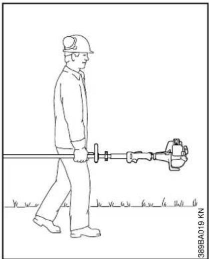
To reduce the risk of injury from loss of control and blade contact, never carry or transport your power tool with the cutting attachment moving.
natural_image
Line drawing of a worker in hard hat carrying a long tool, standing on grass (no text or symbols)It may be carried only in a horizontal position. Grip the shaft in a manner that the machine is balanced horizontally. Keep the hot muffler away from your body and the cutting attachment behind you.
WARNING
Always shut off the engine and make sure that the cutting attachment has stopped before putting an edger down. When transporting it in a vehicle, properly secure it to prevent turnover, fuel spillage and damage to the unit.
Fuel
Your STIHL power tool uses an oil-gasoline mixture for fuel (see the "Fuel" chapter in this instruction manual).
English

WARNING
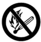
Gasoline is an extremely flammable fuel. If spilled and ignited by a spark or other ignition source, it can cause fire and serious burn injury or property damage. Use extreme caution when handling gasoline or fuel mix. Do not smoke or bring any fire or flame near the fuel or the power tool. Note that combustible fuel vapor may escape from the fuel system.
Fueling Instructions

WARNING
To reduce the risk of fire and serious personal injury, always place the power tool on the ground before attempting to fuel the machine.

WARNING

Pick a Safe Location
To reduce the risk of fire and explosion, fuel your power tool in a well-ventilated area, outdoors away from flames, pilot lights, heaters, electric motors, and other sources of ignition. Vapors can be ignited by a spark or flame many feet away. Select bare ground for fueling and move at least 10 feet (3 m) from the fueling spot before starting the engine. Wipe off any spilled fuel before starting your power tool. Take care not to get fuel on your clothing. If this happens, change your clothing immediately.
Allow the Power Tool to Cool Before Removing the Fuel Cap

WARNING
Gasoline vapor pressure may build up inside the fuel tank. The amount of pressure depends on a number of factors such as the fuel used, altitude and temperature. To reduce the risk of burns and other personal injury from escaping gas, vapor and fumes, always shut off the engine and allow it to cool before removing the fuel cap.
The engine is air cooled. When it is shut off, cooling air is no longer drawn across the cylinder and engine temperatures will rise for several minutes before starting to cool. In hot environments, cooling will take longer. To reduce the risk of burns and other personal injury from escaping gas, vapor and fumes, allow the power tool to cool. If you need to refuel before completing a job, turn off the machine and allow the engine to cool before opening the fuel tank.
Fuel Spraying or "Geysering"

WARNING
Removing the cap on a pressurized fuel tank can result in gasoline, vapors and fumes being forcefully sprayed out from the fuel tank in all directions. The escaping gasoline, vapors or fumes can cause serious personal injury, including fire and burn injury, or property damage.
Sometimes also referred to as "fuel geysering," fuel spraying is an expulsion of fuel, vapors and fumes which can occur in hot conditions, or when the engine is hot, and the tank is opened without allowing the power tool to cool adequately. It is more likely to occur when the fuel tank is half full or more.
Pressure is caused by fuel and heat and can occur even if the engine has not been running. When gasoline in the fuel tank is heated (by ambient temperatures, heat from the engine, or other sources), vapor pressure will increase inside the fuel tank.
Some blends of gasoline, particularly those designed for use in winter, are more volatile and may cause tanks to pressurize more quickly or create greater pressure. At higher altitudes, fuel tank pressurization is more likely.
How to Avoid Fuel Spraying
Removing the fuel cap on a pressurized tank can result in gasoline, vapors and fumes being forcefully sprayed out from the fuel tank in all directions. To reduce the risk of burns, serious injuries or property damage from fuel spraying:
– Follow the fueling instructions in this chapter.
- Always assume your fuel tank is pressurized.
- Allow the power tool to cool before removing the fuel cap.
- In hot environments, cooling will take longer.
- The engine is air cooled. When it is shut off, cooling air is no longer drawn across the cylinder and the engine temperature will rise for several minutes before starting to cool.
After the power tool has cooled appropriately, follow the safety instructions in this chapter for removing the cap.
Never remove the fuel filler cap by turning it directly to the open position. First check for residual pressure in the tank by slowly turning the cap approximately 1/2 turn counterclockwise. The cap should be held in place by the threads while allowing residual vapor/pressure to be relieved. Once the fumes or vapor have been relieved, turn the cap further until it can be removed from the tank opening.
Use only good quality fuel that is appropriate for the season (summer v. winter blends). Some blends of gasoline, particularly winter blends, are more volatile and can contribute to fuel spraying.
Removing the Threaded Fuel Filler Cap
WARNING
After allowing the power tool to cool, remove the fuel filler cap slowly and carefully to allow any remaining pressure build-up in the tank to release:
- While maintaining steady, downward pressure, slowly turn the cap approximately 1/2 turn counterclockwise.
- If any significant venting occurs, immediately re-seal the tank by turning the cap clockwise to the closed position. Allow the power tool to cool further before attempting to open the tank.
- Turn the cap to the open position only after the contents of the tank are no longer under pressure.
- Never remove the cap by turning it directly to the open position. First allow the power tool to cool adequately and then release any residual pressure by slowly turning it approximately 1/2 turn counterclockwise.
- Never attempt to remove the cap while the engine is still hot or running.
Installing the Threaded Fuel Filler Cap
WARNING
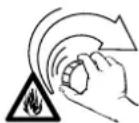
Unit vibrations can cause an improperly tightened fuel filler cap to loosen or come off and spill quantities of fuel. To reduce the risk of fuel spillage and fire, tighten the fuel filler cap by hand with as much force as possible.
Damaged or Broken Cap
If your fuel cap does not tighten properly, it may be damaged or broken. Stop using the power tool and take it to your authorized STIHL dealer for repair.
Vapor Lock
WARNING
Vapor lock occurs when fuel in the fuel line or carburetor vaporizes, causing bubbles to block the free flow of liquid fuel into the carburetor. Vapor lock cannot be relieved or affected by opening the fuel tank. Removing the fuel filler cap without first allowing the power tool to cool adequately can result in fuel spraying. Always follow the instructions in this section when removing the fuel cap.
English
To relieve vapor lock:
- Press the manual fuel pump bulb at least 20 to 30 times – even if the bulb is already filled with fuel – to clear the vapor and send liquid fuel into the carburetor. Then start the power tool. For specific starting instructions, see the appropriate section of your instruction manual.
- If the manual fuel pump bulb will not be filled, place the Choke Lever to the cold start position and pull the starter cord until the engine runs. If the engine does not fire after 10 pulls in the cold start position , place the Choke Lever to the warm start position and start the engine in the warm start position .
- If your power tool will not restart, or if vapor lock occurs again, the power tool is being used in conditions too extreme for the fuel being used. Discontinue use and let the engine cool completely before attempting to start the power tool.
Before Operation

WARNING
Always check your power tool for proper condition and operation before starting, particularly the throttle trigger, throttle trigger lockout, stop switch, cutting blade, deflector and harness. The throttle trigger must move freely and always spring back to the idle position. Never attempt to modify the controls or safety devices.

WARNING
Check fuel system for leaks, especially the visible parts, e.g., filler cap, hose connections, manual fuel pump (only for power tools equipped with a manual fuel pump). Do not start the engine if there are leaks or damage – risk of fire. Have the power tool repaired by a STIHL servicing dealer before using it.

WARNING
Never operate your power tool if it is damaged, improperly adjusted or maintained, or not completely and securely assembled.

WARNING
Check that the spark plug boot is securely mounted on the spark plug – a loose boot may cause arcing that could ignite combustible fumes and cause a fire.

WARNING
Do not mount any cutting attachment to a unit without proper installation of all required parts. Failure to use the proper parts may cause the blade to fly off and seriously injure the operator or bystanders.

WARNING
The cutting attachment must be properly tightened and not damaged. Inspect for loose parts (nuts, screws, etc.) and for cracked, bent, warped or damaged blades. Replace a damaged blade before using the power tool.
Keep the handles clean and dry at all times; it is particularly important to keep them free of moisture, pitch, oil, fuel mix, grease or resin in order for you to maintain a firm grip and properly control your power tool.

WARNING
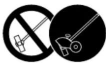
To reduce the risk of personal injury to the operator from blade contact and thrown objects, make sure your unit is equipped with the proper deflector, handle and harness.
natural_image
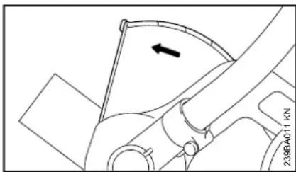
Technical line drawing of a mechanical component with an arrow indicating direction (no text or symbols)An arrow on the deflector shows the correct direction of rotation of the cutting blade.
The arrow on the deflector must always face away from you, so that cuttings and other debris will be diverted away from the machine and your position (see chapter "Working Techniques".)
For proper control and less fatigue during operation, adjust the loop handle to suit your size before starting work.
For specific starting instructions, see the appropriate section of your instruction manual.
Starting

WARNING
Start the engine at least 10 feet (3 m) from the fueling spot, outdoors only.
For specific starting instructions, see the appropriate section of your manual. Place the power tool on firm ground or other solid surface in an open area. Maintain good balance and secure footing.

WARNING
To reduce the risk of injury from blade contact, be absolutely sure that the cutting attachment is clear of you and all other obstructions and objects, including the ground, because when the engine starts at starting-throttle, engine speed will be fast enough for the clutch to engage and move the cutting attachment.
Once the engine has started, immediately blip the throttle trigger, which should release the starting throttle and allow the engine to slow down to idle.
With the engine running only at idle, attach the power tool to the spring hook of your harness (see appropriate chapter of this manual.)

WARNING
Your power tool is a one-person machine. Do not allow other persons in the general work area, even when starting.

WARNING
To reduce the risk of injury from loss of control, do not attempt to "drop start" your power tool.

WARNING
When you pull the starter grip, do not wrap the starter rope around your hand. Do not let the grip snap back, but guide the starter rope to rewind it properly. Failure to follow this procedure may result in injury to your hand or fingers and may damage the starter mechanism.
Important Adjustments

WARNING
To reduce the risk of personal injury from loss of control or contact with the running cutting attachment, do not use your unit with incorrect idle adjustment. At correct idle speed, the cutting attachment should not move. For directions on how to adjust idle speed, see the appropriate section of your instruction manual.
If you cannot set the correct idle speed, have your STIHL dealer check your power tool and make proper adjustments and repairs.

WARNING
This unit is equipped with an ignition system that is normally in operational readiness. After the setting lever is used to stop the engine, it automatically springs back to the "on" position. If the engine is warm, it may be possible to start it by simply pulling the starter rope, with no further adjustments. To reduce the risk of injury, be particularly alert to keep children away from the unit.
During Operation
Holding and Controlling the Power Tool
natural_image
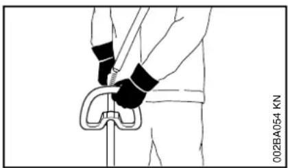
Illustration of a person performing a knuckle lift exercise (no text or symbols)Always hold the unit firmly with both hands on the handles while you are working. Wrap your fingers and thumbs around the handles.
Your right hand should grip the rear handle. This also applies to left-handers.

WARNING
To reduce the risk of injury from loss of control, never work on a ladder or on any other insecure support. Never hold the cutting attachment above waist height.
English

WARNING

Never attempt to operate your power tool with one hand. Loss of control of the power tool resulting in serious or fatal injury may result. To reduce the risk of cut injuries, keep hands and feet away from the cutting attachment. Never touch a moving cutting attachment with your hand or any other part of your body.

WARNING
Do not overreach. Keep proper footing and balance at all times. Special care must be taken in slippery conditions (wet ground, snow) and in difficult, overgrown terrain. Watch for hidden obstacles such as tree stumps, roots and ditches to avoid stumbling. For better footing, clear away scrub and cuttings. Be extremely cautious when working on slopes or uneven ground.
Working Conditions
Operate and start your power tool only outdoors in a well ventilated area. Operate it under good visibility and daylight conditions only. Work carefully.

WARNING

As soon as the engine is running, this product generates toxic exhaust fumes containing chemicals, such as unburned hydrocarbons (including benzene) and carbon monoxide, that are known to cause respiratory problems, cancer, birth defects, or other reproductive harm. Some of the gases (e.g. carbon monoxide) may be colorless and odorless. To reduce the risk of serious or fatal injury / illness from inhaling toxic fumes, never run the machine indoors or in poorly ventilated locations.

WARNING
If the vegetation being cut or the surrounding ground is coated with a chemical substance (such as an active pesticide or herbicide), read and follow the instructions and warnings that accompanied the substance at issue.

WARNING
Inhalation of certain dusts, especially organic dusts such as mold or pollen, can cause susceptible persons to have an allergic or asthmatic reaction. Substantial or repeated inhalation of dust and other airborne contaminants, in particular those with a smaller particle size, may cause respiratory or other illnesses. Control dust at the source
where possible. Use good work practices, such as operating the unit so that the wind or operating process directs any dust raised by the power tool away from the operator. Follow the recommendations of EPA / OSHA / NIOSH and occupational and trade associations with respect to dust ("particulate matter".) When the inhalation of dust cannot be substantially controlled, i.e., kept at or near the ambient (background) level, the operator and any bystanders should wear a respirator approved by NIOSH / MSHA for the type of dust encountered.
Operating Instructions

WARNING
Do not operate your power tool using the starting throttle lock, as you do not have control of the engine speed.
In the event of an emergency, switch off the engine immediately – move the slide control / stop switch to 0 or STOP.

WARNING
The cutting attachment continues to rotate for a short period after the throttle trigger is released (flywheel effect.)

WARNING
The rotating cutting attachment may fling foreign objects directly or by ricochet a great distance.
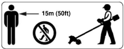
To reduce the risk of eye and other injury always wear proper eye protection (see the chapter on "Proper Clothing") and ensure that bystanders are at least 15 m (50 feet) away. To reduce the risk of damage to property, also maintain this distance from such objects as vehicles or windows. Even maintaining a minimum distance of 15 meters cannot exclude the potential danger. Any coworkers who must be in the restricted area should also wear goggles or protective glasses. Stop the engine immediately if you are approached.
WARNING

Inspect the work area: To reduce the risk of injury, remove stones, pieces of metal and other solid objects which could be thrown 15 meters or more by the cutting attachment or damage the cutting attachment and property (e.g. parked vehicles, windows).
WARNING
During cutting, check the tightness and the condition of the cutting attachment at regular short intervals with the engine and attachment stopped. If the behavior of the attachment changes during use, stop the engine immediately, wait until
the cutting attachment stops, and check the nut securing the attachment for tightness and the blade for cracks, wear and damage.
WARNING
A loose blade may vibrate, crack, break or come off the edger, which may result in serious or fatal injury. Make sure that the cutting attachment is properly tightened. Use the wrench supplied or one of sufficient length to obtain the proper torque. If the blade loosens after being properly tightened, stop work immediately. The retaining nut may be worn or damaged and should be replaced. If the blade continues to loosen, see your STIHL dealer. Never use an edger with a loose cutting attachment.
WARNING
Replace a cracked, bent, warped, damaged, dull or worn out blade immediately, even if damage is limited to superficial cracks. Such attachments may shatter at high speed and cause serious or fatal injury.
WARNING
When using your edger, avoid cutting close to fences, sides of buildings, tree trunks, stones or other such objects that could cause the power tool to kick out or could cause damage to the blade.
WARNING
If a rotating metal blade strikes a rock or other hard object, sparks may be created, which can ignite flammable materials under certain circumstances.
Flammable materials can include dry vegetation and brush, particularly when weather conditions are hot and dry. When there is a risk of fire or wildfire, do not use metal blades around flammable materials or around dry vegetation or brush. Contact your local fire authorities or the U.S. Forestry Service if you have any question about whether vegetation and weather conditions are suitable for the use of a metal blade.
WARNING
If the blade or deflector becomes clogged or stuck, always shut off the engine and make sure the cutting attachment has stopped before cleaning. Grass, weeds, etc. should be cleaned off the blade at regular intervals.
WARNING
To reduce the risk of unintentional rotation of the cutting attachment and injury, always shut off the engine before replacing the cutting attachment.
WARNING
The gearbox becomes hot during operation. To reduce the risk of burn injury, do not touch the gear housing when it is hot.
WARNING
Never modify your muffler. Any modification could cause an increase in heat radiation, sparks or sound level, thereby increasing the risk of fire, burn injury or hearing loss. You may also permanently damage the engine. Have your muffler serviced and repaired by your STIHL servicing dealer only.
English

WARNING
The muffler and other parts of the engine (e.g. fins of the cylinder, spark plug) become hot during operation and remain hot for a while after stopping the engine. To reduce risk of burns, do not touch the muffler and other parts while they are hot. Keep the area around the muffler clean. Remove excess lubricant and all debris such as pine needles, branches or leaves. Let the engine cool down sitting on concrete, metal, bare ground or solid wood away from any combustible substances.

WARNING
An improperly mounted or damaged cylinder housing or a damaged/deformed muffler shell may interfere with the cooling process of the muffler. To reduce the risk of fire or burn injury, do not continue work with a damaged or improperly mounted cylinder housing or a damaged/deformed muffler shell.
Your muffler is furnished with a spark arresting screen designed to reduce the risk of fire from the emission of hot particles. Never operate your unit with a missing or damaged spark arresting screen. If your gas/oil mix ratio is correct (i.e., not too rich), this screen will normally stay clean as a result of the heat from the muffler and need no service or maintenance. If you experience loss of performance and you suspect a clogged screen, have your muffler maintained by a STIHL servicing dealer. Some state or federal laws or regulations may require a properly maintained spark arrestor for certain uses. See the "Maintenance, Repair and Storing" section of these Safety Precautions. Remember that the risk of a brush or forest fire is greater in hot or dry conditions.

WARNING

Some STIHL power tools are equipped with a catalytic converter, which is designed to reduce the exhaust emissions of the engine by a chemical process in the muffler. Due to this process, the muffler does not cool down as rapidly as conventional mufflers when the engine returns to idle or is shut off. To reduce the risk of fire and burn injuries when using a catalytic converter, always set your power tool down in the upright position and never locate it where the muffler is near dry brush, grass, wood chips or other combustible materials while it is still hot.
USING THE CUTTING ATTACHMENT
For an illustration of the cutting attachment and instructions on proper mounting see the chapter on "Replacing the Cutting Blade" in your instruction manual.

WARNING
To reduce the risk of severe or fatal injury from blade contact and / or loss of control, never attempt to use a metal blade on an FC model for which it is not authorized.
MAINTENANCE, REPAIR AND STORING
Maintenance, replacement, or repair of the emission control devices and systems may be performed by any nonroad engine repair establishment or individual. However, if you make a warranty claim for a component which has not been serviced or maintained properly, STIHL may deny coverage.

WARNING
Use only identical STIHL replacement parts for maintenance and repair. Use of non-STIHL parts may cause serious or fatal injury.
Strictly follow the maintenance and repair instructions in the appropriate sections of your instruction manual.

WARNING
Always stop the engine and make sure that the cutting attachment is stopped before doing any maintenance or repair work or cleaning the power tool. Do not attempt any maintenance or repair work not described in your instruction manual. Have such work performed by your STIHL servicing dealer only.
Wear gloves when handling or performing maintenance on blades.
WARNING
Use the specified spark plug, and make sure it and the ignition lead are always clean and in good condition. Always press the spark plug boot snugly onto the spark plug terminal of the proper size. (Note: If the terminal has a detachable SAE adapter nut, it must be securely attached.) A loose connection between the spark plug and the ignition wire connector in the boot may create arcing that could ignite combustible fumes and cause a fire.
WARNING
Never test the ignition system with the spark plug boot removed from the spark plug or with a removed spark plug, since uncontained sparking may cause a fire.
WARNING
Do not operate your power tool if the muffler is damaged, missing or modified. An improperly maintained muffler will increase the risk of fire and hearing loss. Your muffler is equipped with a spark-arresting screen to reduce the risk of fire; never operate your power tool if the screen is missing, damaged or clogged. Remember that the risk of a brush or forest fire is greater in hot or dry weather.
In California, it is a violation of § 4442 or § 4443 of the Public Resources Code to use or operate gasoline-powered tools on forest-covered, brush-covered or grass-covered land unless the engine's exhaust system is equipped with a complying spark arrester that is maintained in effective working order. The owner/operator of this product is
responsible for properly maintaining the spark arrester. Other states or governmental entities/agencies, such as the U.S. Forest Service, may have similar requirements. Contact your local fire agency or forest service for the laws or regulations relating to fire protection requirements.
WARNING
Never repair damaged cutting attachments by welding, straightening or modifying the shape. This may cause parts of the cutting attachment to come off and result in serious or fatal injuries.
Tighten all nuts, bolts and screws, except the carburetor adjustment screws, after each use.
Do not clean your machine with a pressure washer. The solid jet of water may damage parts of the machine.
Store the power tool in a dry and high or locked location out of reach of children.
Before storing for longer than a few days, always empty the fuel tank. See chapter "Storing the Machine" in the instruction manual.
Using the Unit
natural_image
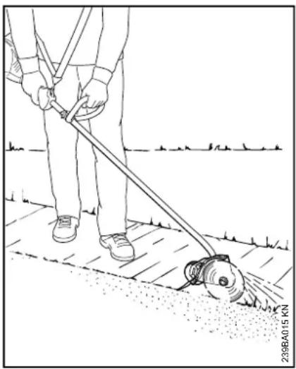
Line drawing of a person using a power tool on a paved surface, with no visible text or symbolsYour power edger is designed to produce sharp contoured borders around lawns and flower beds. It will cut almost all types of grass, weeds and soft green plants.
Preparations
If the work area is very dry, spray it lightly with water: this softens the soil and ensures that less dust is created. Slightly damp green plants are easier to cut.
WARNING
Clear away all obstacles and solid objects from the work area.
English
- Plan the best route for edging. Always hold and operate your edger on the right-hand side of your body.
Adjusting Depth of Cut
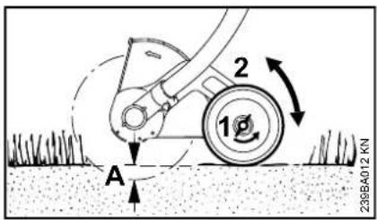
- Shut down the engine.
● Loosen the wingnut (1) counterclockwise. - Push wheel (2) upwards to increase the depth of cut (A) or downwards to reduce the depth of cut (A).
Adjust correctly
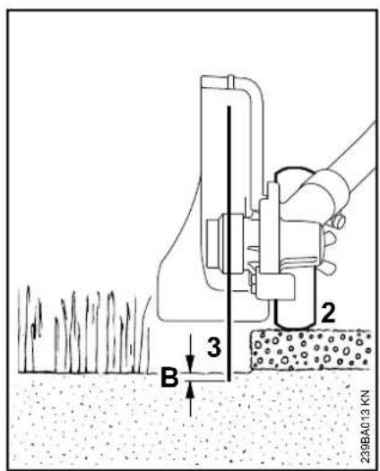
The depth of cut depends on the unevenness of the ground, your height and the way you hold the edger. Use the following procedure:
- Adjust the depth wheel (2) so that the blade (3) just touches the ground or breaks the surface of the soil by no more than 5 mm (B)
natural_image
Technical line drawing of a mechanical component with no visible text or symbols● Tighten down the wingnut clockwise.
● Standing in the normal working position, check the depth of cut again and correct it if necessary.
natural_image
Line drawing of a person using a power tool to clean or manage equipment on a paved surface (no text or symbols)WARNING
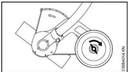
Do not adjust the deflector.
The deflector has been set at the factory so that the arrow on the deflector and the open side point away from the
operator. This ensures that cuttings and other debris are directed away from the power tool and operator.
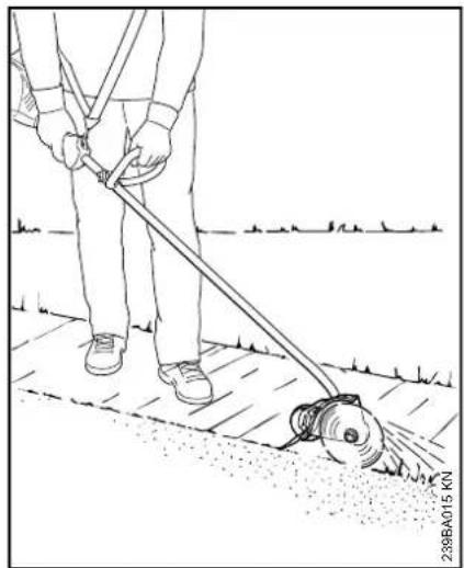
Edging
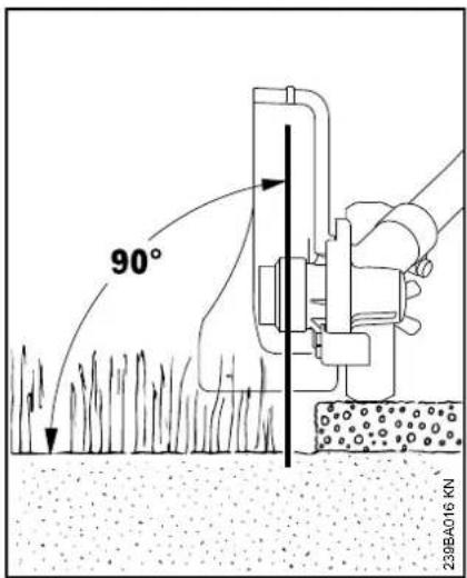
- Start the engine
- Start the cut at no less than half throttle and continue cutting at full throttle.
● Hold and guide your power tool so that the blade is vertical. - Cut steadily so that the engine is not lugged down – do not apply force.
● Operate at no more than a normal walking pace. - Do not push the blade into the ground.
● Always walk forwards when cutting, do not pull the unit towards you.
● Cut at a steady pace to avoid having to make several passes.
natural_image
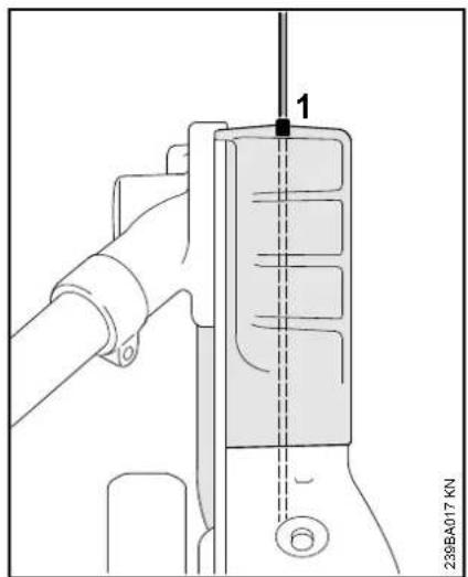
Technical diagram of a mechanical assembly with a vertical component labeled '1' and a base marked '239BA017 KN' (no readable text or symbols beyond label)- Use the gunning sight (1) to line the blade up with the edge of the bed.
Mounting the Loop Handle
Your new power tool comes with the loop handle mounted on the drive tube, but it must be turned and lined up to suit your requirements.
Adjusting loop handle with star knob screw
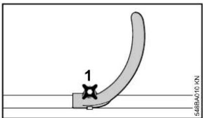
- Loosen the star knob screw (1).
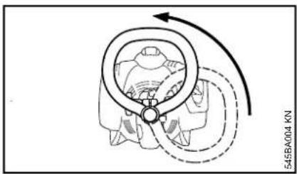
natural_image
Diagram of a mechanical component with directional arrows indicating motion (no text or symbols)● Turn the handle to the vertical position.
English
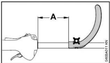
The loop handle can be adjusted to suit the height and reach of the operator and the application by changing distance (A).
Recommendation: distance (A): about 6 in (15 cm)
- Slide the handle to the required position.
● Tighten down the star knob so that the handle cannot be rotated on the shaft.
Adjusting loop handle without star knob screw
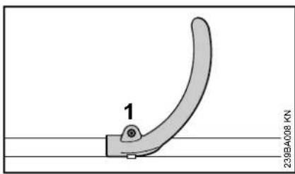
- Use the combination wrench to loosen the screw (1).
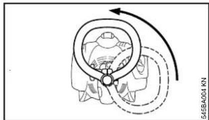
natural_image
Diagram of a mechanical component with directional arrows indicating motion (no text or symbols)● Turn the handle to the vertical position.
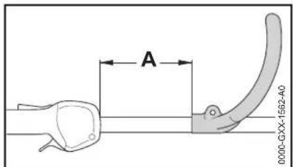
The loop handle can be adjusted to suit the height and reach of the operator and the application by changing distance (A).
Recommendation: distance (A): about 6 in (15 cm)
- Slide the handle to the required position.
● Tighten down the screw with the combination wrench so that the handle cannot be rotated on the drive tube.
Mounting the Cutting Blade
natural_image
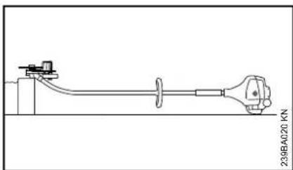
Technical line drawing of a mechanical assembly with no visible text or symbols- Place the edger so that the blade mounting (1) faces upwards
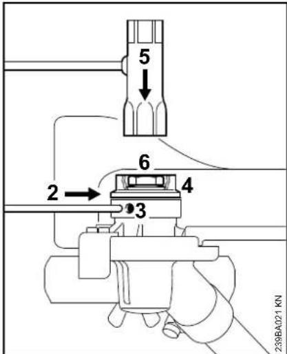
- Insert the locking pin (2) as far as possible into the bore (3), push lightly and rotate back and forth a little together with the thrust washer (4) until the shaft is blocked.
● Fit Allen wrench (5) onto nut (6).
● Turn nut clockwise (left-hand thread) and remove it.
- Remove the thrust washer.
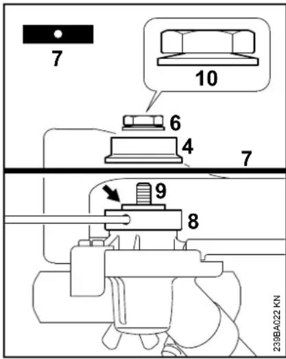
- Position the blade (7) on the thrust plate (8).
WARNING
The collar (arrow) must engage the hole in the blade.
● Fit the thrust washer (4) on the shaft (9) and block the shaft.
- Screw nut (6) counterclockwise onto shaft and tighten.
WARNING
If the cup spring (10) on the nut (6) becomes fatigued, then the nut must be replaced!
Fuel
This engine is certified to operate on unleaded gasoline and the STIHL two-stroke engine oil at a mix ratio of 50:1.
Your engine requires a mixture of high-quality gasoline and two-stroke air cooled engine oil.
Use mid-grade unleaded gasoline with a minimum octane rating of 89 ((R+M)/2) and no more than 10% ethanol content.
NOTICE
Fuel with an octane rating below 89 may increase engine temperatures. This, in turn, increases the risk of piston seizure and damage to the engine.
The chemical composition of the fuel is also important. Some fuel additives not only detrimentally affect elastomers (carburetor diaphragms, oil seals, fuel lines, etc.), but magnesium castings and catalytic converters as well. This could cause running problems or damage the engine. For this reason STIHL recommends that you use only quality unleaded gasoline!
NOTICE
Gasoline with an ethanol content of more than 10% can cause running problems and major damage in engines and should not be used.
For further details, see www.STIHLusa.com/ethanol
The ethanol content in gasoline affects engine speed – it may be necessary to readjust the carburetor if you use fuels with various ethanol contents.
WARNING
To reduce the risk of personal injury from loss of control and/or contact with the running cutting tool, do not use your unit with an incorrect idle adjustment. At correct idle speed, the cutting tool should not move.
If your machine's idle speed is incorrectly adjusted, have your authorized STIHL servicing dealer check your machine and make the proper adjustments and repairs.
The idle speed and maximum speed of the engine change if you switch from a fuel with a certain ethanol content to a fuel with a much higher or lower ethanol content.
This problem can be avoided by always using fuel with the same ethanol content.
To ensure the maximum performance of your STIHL engine, use a high quality 2-cycle engine oil. To help your engine run cleaner and reduce harmful carbon deposits, STIHL recommends using STIHL HP Ultra 2-cycle engine oil or ask your dealer for an equivalent fully synthetic 2-cycle engine oil.
To meet the requirements of EPA and CARB we recommend to use STIHL HP Ultra oil.
STIHL MotoMix
STIHL recommends the use of STIHL MotoMix. STIHL MotoMix has a high octane rating and ensures that you always use the right gasoline/oil mix ratio.
English
STIHL MotoMix uses STIHL HP Ultra two-stroke engine oil suited for high performance engines.
For further details, see www.STIHLusa.com/ethanol
If not using MotoMix, use only STIHL two-stroke engine oil or equivalent high-quality two-stroke engine oils that are designed for use in air cooled two-cycle engines.
The use of non-seasonal gasoline blends may increase the potential for pressure to build in the fuel tank during operation. For example, using a winter blend during the summer will increase pressure in the fuel tank. Always use gasoline blends appropriate to the season, altitude and other environmental factors.
Do not use NMMA or TCW rated (two-stroke water cooled) mix oils or other mix oils that state they are for use in both water cooled and air cooled engines (e.g., outboard motors, snowmobiles, chain saws, mopeds, etc.).

WARNING
Take care when handling gasoline. Avoid direct contact with the skin and avoid inhaling fuel vapor. When filling at the pump, first remove the container from your vehicle and place the container on the ground before filling. To reduce the risk of sparks from static discharge and resulting fire and/or explosion, do not fill fuel containers that are sitting in or on a vehicle or trailer.
The container should be kept tightly closed in order to limit the amount of moisture that gets into the mixture.
The machine's fuel tank should be cleaned as necessary.
Fuel mix ages
If not using MotoMix, only mix sufficient fuel for a few days of work, not to exceed 30 days of storage. Store in approved fuel-containers only. When mixing, pour oil into the container first, and then add gasoline. Close the container and shake it by hand to ensure proper mix of oil and gasoline.

WARNING
Shaking fuel can cause pressure to build in the fuel container. To reduce the risk of fire and severe personal injury or property damage from fuel spraying, allow the fuel container to sit for several minutes before opening. Open the container slowly to release any residual pressures. Never open the fuel container in the vicinity of any ignition source. Read and follow all warnings and instructions that accompany your fuel container.
| GasolineUS gal. US fl.oz. | Oil (STIHL 50:1 or equivalent high-quality oils) |
| 1 | 2.6 |
| 2 1/2 6.4 | |
| 5 12.8 |
Dispose of empty mixing-oil containers only at authorized disposal locations.
Fueling

WARNING

Removing the cap on a pressurized fuel tank can result in gasoline, vapors and fumes being forcefully sprayed out from the tank in all directions. The escaping gasoline, vapors or fumes, sometimes referred to as fuel spraying or "geysering," can cause serious personal injury, including fire and burn injury, or property damage.
Fuel spraying can occur when the engine is hot and the tank is opened while under pressure. It can occur in hot environments even if the engine has not been running. Spraying is more likely to occur when the fuel tank is half full or more.
Avoid Injuries from Fuel Spraying.
Always follow the fueling instructions in this manual:
- Treat every fuel tank as if it is pressurized, particularly if it is half full or more.
-
Always allow the power tool to cool adequately before attempting to open the fuel tank or refueling; this will take longer in hot conditions.
-
Never remove the cap by turning it directly to the open position. Turn it first approximately 1/2 of a turn counter-clockwise to relieve any residual pressure.
- Never open the fuel tank while the engine is still hot or running.
- Never open the fuel tank or re-fuel the power tool near any sparks, flames or other ignition sources.
- Pick the right fuel: use only good quality (89 octane or higher), fresh fuel blended for the season.
- Vapor lock: do not remove the fuel cap in an effort to relieve vapor lock. Removing the cap has no effect on vapor lock.
- Be aware that fuel spraying is more likely at higher altitudes.

Preparations
natural_image
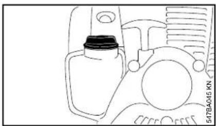
Line drawing of a mechanical device with a bottle and fan (no text or symbols)● Before fueling, clean the filler cap and the area around it to ensure that no dirt falls into the tank.
- Position the machine so that the filler cap is facing up.
WARNING
In order to reduce the risk of fire and other personal injury from escaping gas vapor and fumes, remove the fuel filler cap slowly and carefully so as to allow any pressure build-up in the tank to release slowly.
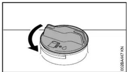
Opening
natural_image
Diagram of a circular device with a rotating arrow indicating rotation, no text or symbols presentWARNING
After allowing the power tool to cool, remove the fuel filler cap slowly and carefully to allow any remaining pressure build-up in the tank to release:
● While maintaining steady, downward pressure, slowly turn the cap approximately a 1/2 turn counter-clockwise.
- If any significant venting occurs, immediately re-seal the tank by turning the cap clockwise to the closed position. Allow the power tool to cool further before attempting to open the tank.
● Turn the cap to the open position only after the contents of the tank are no longer under pressure.
- Remove the fuel filler cap.
WARNING
Never remove the cap by turning it directly to the open position. First allow the power tool to cool adequately and then release any residual pressure by slowly turning the cap approximately 1/2 turn counter-clockwise. Never attempt to remove the cap while the engine is still hot or running.
Refueling
Take care not to spill fuel while fueling and do not overfill the tank – leave approximately 1/2" (13 mm) air space.
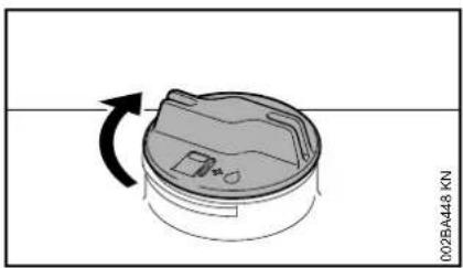
Closing
natural_image
Diagram of a circular device with a rotating arrow and component, no text or symbols presentWARNING
An improperly tightened fuel filler cap can loosen or come off and spill quantities of fuel. To reduce the risk of fuel spillage and fire from an improperly installed fuel cap, tighten the fuel filler cap by hand with as much force as possible:
English
- If your fuel cap still does not tighten properly, it may be damaged or broken. Stop using the power tool and take it to your authorized STIHL dealer for repair or replacement.
Starting / Stopping the Engine
Controls
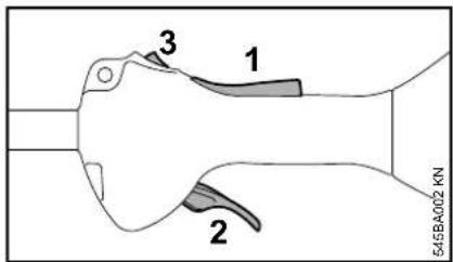
1 Throttle trigger lockout
2 Throttle trigger
3 Momentary stop switch with Run and 0 = Stop positions.
Function of stop switch and ignition system
The momentary stop switch is normally in the Run position: Ignition is on in this position – the engine is ready to start and may be started. If the momentary stop switch is moved to the 0 position, the ignition is off. It is automatically switched on again after the engine comes to a standstill.
Starting the Engine
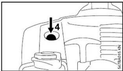
- Press the manual fuel pump bulb (4) at least five times – even if the bulb is already filled with fuel.
Cold engine (cold start)
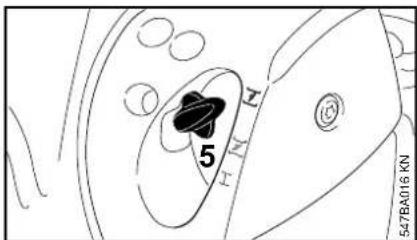
- Press in the choke lever (5) and turn it to 1 at the same time.
Warm engine (warm start)
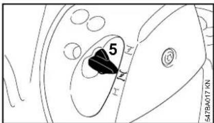
- Press in the choke lever (5) and turn it to ✕ at the same time.
Also use this setting if the engine has been running but is still cold.
Starting
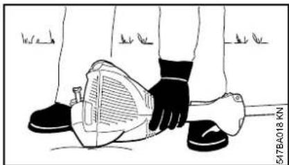
natural_image
Illustration of a person holding a small mechanical device with a tool, no text or symbols present- Place the unit on the ground: Check that the cutting blade is not touching the ground of any other obstacles.
● Make sure you have a firm footing. - Hold the unit firmly on the ground with your left hand and press down – do not touch the throttle trigger or throttle trigger lockout.
NOTICE
Do not stand or kneel on the drive tube.

natural_image
Line drawing of a person's legs and feet wearing gloves, with one foot adjusting the seat area (no text or symbols)- Pull the starter grip slowly with your right hand until you feel it engage and then continue pulling it slowly and steadily. Do not pull out the starter rope to full length – it might otherwise break.
- Do not let the starter grip snap back. Guide it slowly back into the housing so that the starter rope can rewind properly.
- Continue cranking until the engine runs.
As soon as the engine runs
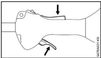
- Press down the throttle trigger lockout and open the throttle – the choke lever moves to the run position I. After a cold start, warm up the engine by opening the throttle several times.
WARNING
Make sure the carburetor is correctly adjusted. The cutting blade must not rotate when the engine is idling.
Your machine is now ready for operation.
Shut off the engine.
- Move the momentary stop switch in the direction of 0 – the engine stops – release the momentary stop switch – it springs back to the run position.
Other hints on starting
Engine stalls in cold start position 1 or under acceleration
- Move the choke lever to 7 and continue cranking until the engine runs.
English
Engine does not start in warm start position ↗
- Move the choke lever to and continue cranking until the engine runs.
If the engine does not start
- Check that choke lever is in correct position.
- Check that there is fuel in the tank and refuel if necessary.
- Check that the spark plug boot is properly connected.
- Repeat the starting procedure.
Engine is flooded
- Move the choke lever to I and continue cranking until the engine runs.
Fuel tank run until dry
- After refueling, press the manual fuel pump bulb at least five times – even if the bulb is filled with fuel.
- Set the choke lever to suit the engine temperature.
- Now start the engine.
Operating Instructions Cleaning the Air Filter
During break-in period
A factory-new machine should not be run at high revs (full throttle off load) for the first three tank fillings. This avoids unnecessary high loads during the break-in period. As all moving parts have to bed in during the break-in period, the frictional resistances in the engine are greater during this period. The engine develops its maximum power after about 5 to 15 tank fillings.
During Operation
After a long period of full throttle operation, allow the engine to run for a short while at idle speed so that engine heat can be dissipated by the flow of cooling air. This protects engine-mounted components (ignition, carburetor) from thermal overload.
After Finishing Work
Storing for a short period: Wait for the engine to cool down. Empty the fuel tank and keep the machine in a dry place, well away from sources of ignition, until you need it again. For longer out-of-service periods – see "Storing the Machine".
If there is a noticeable loss of engine power
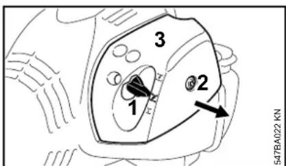
- Move the choke lever (1) to .
● Turn the screw (2) in the filter cover (3) counterclockwise until the cover is loose. - Ease the filter cover (3) over the choke lever and lift it away.
● Clean away loose dirt from around the filter.
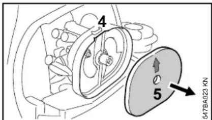
- Reach into the recess (4) in the filter housing and take out the felt filter (5).
- Fit a new felt filter element (5). As a temporary measure you can knock it out on the palm of your hand or blow it out with compressed air. Do not wash.
NOTICE
Replace damaged parts.
- Fit the felt filter (5) in the filter housing, make sure it is properly seated – the arrow points to the recess.
- Move the choke lever (1) to .
● Fit the filter cover in position, making sure the screw is square. Tighten down the screw.
Engine Management Adjusting the Carburetor
Exhaust emissions are controlled by the design of the engine and components (e.g. carburation, ignition, timing and valve or port timing).
The carburetor comes from the factory with a standard setting.
On this machine it is no longer necessary to adjust the carburetor.
It has been set at the factory to provide an optimum fuel-air mixture in all locations and operating conditions.
Adjusting Idle Speed
Engine stops while idling
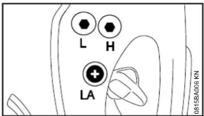
● Warm up the engine for about 3 minutes.
- Turn the idle speed screw (LA) slowly clockwise until the engine runs smoothly – the cutting attachment must not move.
Cutting attachment runs when engine is idling
● Turn the idle speed screw (LA) counterclockwise until the cutting attachment stops running and then turn the screw about another 1/2 to 3/4 turn in the same direction.
English

WARNING
If the working tool or cutting attachment continues to run when the engine is idling, have your machine checked and repaired by your servicing dealer.
Spark Plug
If there is a loss of engine power, the machine is difficult to start or runs poorly at idle, first check the spark plug.
Install a new spark plug after approximately 100 operating hours or earlier if the electrodes are eroded/corroded.
The wrong fuel mix (too much engine oil in the gasoline), a dirty air filter and unfavorable running conditions (mostly at part throttle etc.) affect the condition of the spark plug. These factors cause deposits to form on the insulator nose, which may degrade performance.
Removing the Spark Plug
● Shut off the engine.
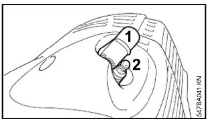
- Remove the spark plug boot (1).
● Unscrew the spark plug (2).
Checking the spark plug
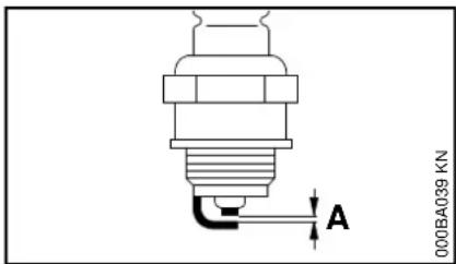
● Clean the spark plug if it is dirty
- Check the electrode gap (A) and readjust if necessary – see "Specifications"
- Use only resistor type spark plugs of the approved range. See the chapter "Specifications" in this instruction manual
Correct the problems that have caused fouling of the spark plug:
- too much oil in fuel mix;
– dirty air filter; or
– unfavorable running conditions, e.g. operating at part throttle.
Engine Running Behavior Storing the Machine
If engine running behavior is unsatisfactory even though the air filter is clean and the carburetor is properly adjusted, the cause may be the muffler.
Have the muffler checked for contamination (carbonization) by your servicing dealer.
STIHL recommends that you have servicing and repair work carried out exclusively by an authorized STIHL servicing dealer.
For periods of 3 months or longer
● Drain and clean the fuel tank in a well ventilated area.
- Dispose of fuel properly in accordance with local environmental requirements.
- Run the engine until the carburetor is dry – this helps prevent the carburetor diaphragms sticking together.
- Thoroughly clean the machine – pay special attention to the cylinder fins and air filter.
- Remove, clean and inspect the cutting blade.
- Store the machine in a dry, high or locked location, out of the reach of children and other unauthorized persons.
WARNING
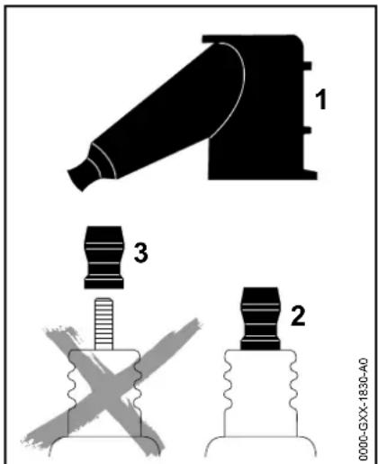
To reduce the risk of fire and burn injury, use only spark plugs authorized by STIHL. Always press the spark plug boot (1) firmly and securely onto the spark plug terminal (2).
Do not use a spark plug with a detachable SAE adapter terminal (3). Arcing may occur that could ignite combustible fumes and cause a fire. This can result in serious injuries or damage to property.
- Only use resistor type spark plugs with solid, non-threaded terminals
Installing the Spark Plug
- Screw the spark plug into the cylinder.
- Press the boot firmly onto the spark plug.
FC 56 C
English
Replacing the Depth Wheel
Have a worn depth wheel replaced by a servicing dealer. STIHL recommends that you have servicing and repair work carried out exclusively by an authorized STIHL servicing dealer.
Depth Wheel
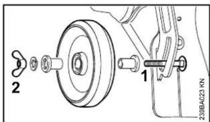
● The end of the thread on the screw (1) is peened over to ensure that the wingnut (2) does not work loose and be lost.
A very high torque has to be applied to remove the wingnut from the screw. If the parts are then reassembled, the captive function is no longer guaranteed. In such a case have the screw and wingnut replaced by a servicing dealer.
Replacing the Skirt
Removing the skirt
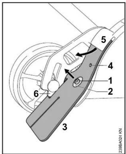
- Undo and remove the screw (1).
- Remove the washer (2)
● Pull the skirt (3) out of the segment (6) and out of the gap (5) in the deflector
Fitting the skirt
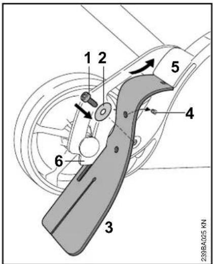
- In order to push the skirt easily into the gap on the deflector, apply a thin coating of resin-free oil to the top of the skirt
- Thread the skirt (3) into the segment (6) and push into the gap (5) of the deflector – the bore in the skirt must be fixed in the arbor (4)
- Place washer (2) onto screw (1).
- Insert and tighten the screw (1)
Replacing the Cutting Blade
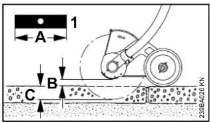
Do not attempt to straighten or weld a bent or cracked blade – it may break – it must be replaced – see "Mounting the Cutting Blade".
STIHL recommends you use only the following original STIHL cutting blades:
Length Thick - Marking ness
200 mm 2.4 mm 4133 / 01
200 mm 3.8 mm 4133 / 02
Do not resharpen the blade.
- Replace the blade (1) if its length (A) is no longer sufficient to maintain the necessary ground clearance (B) and obtain the required depth of cut (C).
Checking Out-of-Balance
To avoid out-of-balance:
- Have your dealer check the blade for out-of-balance on a STIHL balancer (special accessory) – STIHL recommends an authorized STIHL servicing dealer. If blade is out-of-balance, fit a new one – see "Mounting the Cutting Blade".
Checking and Replacing the Wear Guard
Checking the protection against wear
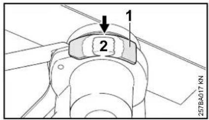
● Before starting up the machine, check that the protection against wear (1) is not damaged
- Replace the protection against wear at the latest when the gearbox (2) becomes visible (arrow)
NOTICE
If worn deflectors are not replaced in time, this can cause serious damage to the gearbox.
Replacing the protection against wear
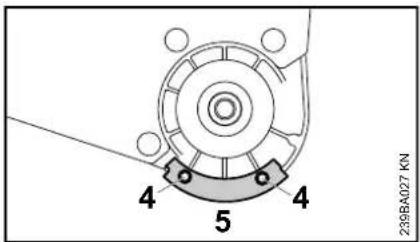
- Remove the blade – see "Fitting the blade"
● Unscrew screws (4) - Replace the protection against wear (5)
● Screw in and tighten screws (4) - Fit the blade – see "Fitting the blade"
English
Inspections and Maintenance by Dealer
Spark arresting screen in muffler

WARNING
To reduce the risk of fire caused by hot particles escaping from the machine, never operate the machine without a spark arresting screen, or with the spark arresting screen damaged. Do not modify the muffler or spark arresting screen. To reduce the risk of fire from accumulated debris such as pine needles, branches or leaves, ensure that the muffler plugs are in place before taking up work.
NOTICE
According to the law or regulations in some countries or federal states, certain operations may only be carried out if a properly serviced spark arresting screen is provided.
- If the engine is down on power, check the spark arresting screen in the muffler.
- If the muffler plugs are missing or damaged, mount new plugs.
STIHL recommends that maintenance and repair work be carried out only by authorized STIHL dealers.
Maintenance and Care
| The following intervals apply to normal operating conditions only. If your daily working time is longer or operating conditions are difficult (very dusty work area, etc.), shorten the specified intervals accordingly. | before starting work | after finishing work or daily | after each refueling stop | weekly | monthly | every 12 months | if problem | if damaged | as required | |
| Complete machine | Visual inspection (condition, leaks) X X | |||||||||
| Clean X | ||||||||||
| Control handle Check operation X | X | |||||||||
| Air filter | Clean X X | |||||||||
| Replace X | ||||||||||
| Manual fuel pump (if fitted) | Check X | |||||||||
| Have repaired by servicing dealer ^1) | X | |||||||||
| Pickup body in fuel tank | Check X | |||||||||
| Replace X X X | ||||||||||
| Fuel tank | Clean X X | |||||||||
| Carburetor | Check idle adjustment – the blade must not rotate | X | X | |||||||
| Readjust idle | X | |||||||||
| Spark plug | Readjust electrode gap | X | ||||||||
| Replace after every 100 operating hours | ||||||||||
| Cooling inlets | Visual inspection | X | ||||||||
| Clean | X | |||||||||
| Spark arresting screen in muffler | Have checked by servicing dealer ^1) | X | ||||||||
| Have cleaned or replaced by servicing dealer ^1) | X | X | ||||||||
| All accessible screws and nuts (not adjusting screws) | Retighten | X | ||||||||
English
| The following intervals apply to normal operating conditions only. If your daily working time is longer or operating conditions are difficult (very dusty work area, etc.), shorten the specified intervals accordingly. | before starting work | after finishing work or daily | after each refueling stop | weekly | monthly | every 12 months | if problem | if damaged | as required | |
| Blade | Visual inspection X X | |||||||||
| Replace X | ||||||||||
| Check tightness of blade X | X | |||||||||
| Safety labels Replace X | ||||||||||
1) STIHL recommends an authorized STIHL servicing dealer.
Main Parts
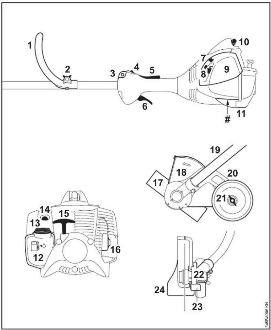
1 Loop Handle
2 Wing Screw
3 Carrying Ring
4 Stop Switch
5 Throttle Trigger Lockout
6 Throttle Trigger
7 Carburetor Adjusting Screws
8 Choke Lever
9 Air Filter Cover
10 Spark Plug Boot
11 Machine Support
12 Fuel Tank
13 Fuel Filler Cap
14 Manual Fuel Pump
15 Starter Grip
16 Muffler with Spark Arresting Screen
17 Cutting Blade
18 Deflector
19 Drive Tube
20 Wheel
21 Wingnut
22 Gearbox
23 Wear Guard
24 Skirt
Serial Number
English
Definitions
1 Loop Handle
For easy control of machine during cutting work.
2 Wing Screw (optional)
Locks loop handle in selected position.
3 Carrying Ring
Connects the edger to the harness.
4 Stop Switch
Switches the engine's ignition off and stops the running engine.
5 Throttle Trigger Lockout
Must be depressed before the throttle trigger can be activated.
6 Throttle Trigger
Controls the speed of the engine.
7 Carburetor Adjusting Screws
For tuning the carburetor.
8 Choke Lever
Eases engine starting by enriching mixture.
9 Air Filter Cover
Covers and protects the air filter element.
10 Spark Plug Boot
Connects the spark plug with the ignition lead.
11 Machine Support
For resting machine on the ground.
12 Fuel Tank
For fuel and oil mixture.
13 Fuel Filler Cap
For closing the fuel tank.
14 Manual Fuel Pump
Provides additional fuel feed for a cold start.
15 Starter Grip
The grip of the pull starter, for starting the engine.
16 Muffler with Spark Arresting Screen Muffler reduces exhaust noises and diverts exhaust gases away from operator. Spark arresting screen is designed to reduce the risk of fire.
17 Cutting Blade
Metal cutting blade for cutting weeds and soft green plants.
18 Deflector
The deflector is designed to reduce the risk of injury from flying objects hurled aside by the cutting blade and from contact with the cutting blade.
19 Drive Tube
Encloses and protects the drive shaft between the engine and gearbox.
20 Wheel
The wheel mounted on the deflector guides the cutting blade of the edger over the ground at a preset height.
21 Wing Nut
Must be loosened to move the wheel for setting the cutting depth.
22 Gearbox
Reduces input speed to required axle speed.
23 Wear Guard
Protects the gearbox from wear.
24 Skirt
The skirt is designed to reduce the risk and injury from flying objects hurled aside by the cutting blade.
Specifications
EPA / CEPA
The Emission Compliance Period referred to on the Emissions Compliance Label indicates the number of operating hours for which the engine has been shown to meet Federal emission requirements.
Category
A = 300 hours
B = 125 hours
C = 50 hours
CARB
The Emission Compliance Period used on the CARB-Air Index Label indicates the terms:
Extended = 300 hours
Intermediate = 125 hours
Moderate = 50 hours
Engine
Single cylinder two-stroke engine
Displacement: 1.66 cu.in
(27.2 cc)
Bore: 1.34 in (34 mm)
Stroke: 1.18 in (30 mm)
Engine power to
1.1 bhp (0.8 kW)
ISO 8893:
at 8,500 rpm
Idle speed: 2,800 rpm
Cut-off speed (rated): 10,000 rpm
Max. output shaft
speed (cutting blade): 8,600 rpm
Ignition System
Electronic magneto ignition
Spark plug (resistor
type): NGK CMR 6 H
Electrode gap: 0.02 in (0.5 mm)
Fuel System
All position diaphragm carburetor with integral fuel pump
Fuel tank capacity: 11.5 fl.oz (0.34 l)
Weight
dry, with deflector and
blade 13.4 lbs (6.1 kg)
Maintenance and Repairs
Users of this unit should carry out only the maintenance operations described in this manual. STIHL recommends that other repair work be performed only by authorized STIHL servicing dealers using genuine STIHL replacement parts.
Genuine STIHL parts can be identified by the STIHL part number, the
STIHL ^ logo and, in some cases, by the STIHL parts symbol G_ . The symbol may appear alone on small parts.
For repairs of any component of this unit's air emissions control system, please refer to the air emissions systems warranty in this manual.
English
Disposal
Observe all country-specific waste disposal rules and regulations.

STIHL products must not be thrown in the garbage can. Take the product, accessories and packaging to an approved disposal site for environment-friendly recycling.
Contact your STIHL servicing dealer for the latest information on waste disposal.
Limited Warranty STIHL Incorpor
STIHL Incorporated Limited Warranty Policy for Non-Emission-Related Parts and Components
This product is sold subject to the STIHL Incorporated Limited Warranty Policy, available at
www.stihlusa.com/warranty.html.
It can also be obtained from your authorized STIHL dealer or by calling 1-800-GO-STIHL (1-800-467-8445).
A separate emissions control system warranty is provided for emission-related components.
rated Federal Emission Control Warranty Statement
Not for California
Your Warranty Rights and Obligations
The U.S. Environmental Protection Agency (EPA) and STIHL Incorporated are pleased to explain the Emission Control System Warranty on your equipment type engine. In the U.S. new 1997 and later model year small off-road equipment engines must be designed, built and equipped, at the time of sale, to meet the U.S. EPA regulations for small non road engines. The equipment engine must be free from defects in materials and workmanship which cause it to fail to conform with U.S. EPA standards for the first two years of engine use from the date of sale to the ultimate purchaser.
STIHL Incorporated must warrant the emission control system on your small off-road engine for the period of time listed below provided there has been no abuse, neglect or improper maintenance of your small off-road equipment engine.
Your emission control system includes parts such as the carburetor and the ignition system. Also included may be hoses, and connectors and other emission-related assemblies.
Where a warrantable condition exists, STIHL Incorporated will repair your small off-road equipment engine at no cost to you, including diagnosis (if the diagnostic work is performed at an authorized dealer), parts, and labor.
Manufacturer's Warranty Coverage
In the U.S., 1997 and later model year small off-road equipment engines are warranted for two years. If any emission-related part on your engine is defective, the part will be repaired or replaced by STIHL Incorporated free of charge.
Owner's Warranty Responsibilities
As the small off-road equipment engine owner, you are responsible for the performance of the required maintenance listed in your instruction manual. STIHL Incorporated recommends that you retain all receipts covering maintenance on your small off-road equipment engine, but STIHL Incorporated cannot deny warranty solely for the lack of receipts or for your failure to ensure the performance of all scheduled maintenance.
Any replacement part or service that is equivalent in performance and durability may be used in non-warranty maintenance or repairs, and shall not reduce the warranty obligations of the engine manufacturer.
As the small off-road equipment engine owner, you should be aware, however, that STIHL Incorporated may deny you warranty coverage if your small off-road equipment engine or a part has failed due to abuse, neglect, improper maintenance or unapproved modifications.
You are responsible for presenting your small off-road equipment engine to a STIHL service center as soon as a problem exists. The warranty repairs will be completed in a reasonable amount of time, not to exceed 30 days.
If you have any questions regarding your warranty rights and responsibilities, please contact a STIHL customer service representative at 1-800-467-8445 or you can write to
STIHL Inc., 536 Viking Drive, P.O. Box 2015, Virginia Beach, VA 23450-2015
www.stihlusa.com
Coverage by STIHL Incorporated
STIHL Incorporated warrants to the ultimate purchaser and each subsequent purchaser that your small off-road equipment engine will be designed, built and equipped, at the time of sale, to meet all applicable emissions regulations. STIHL Incorporated also warrants to the initial purchaser and each subsequent purchaser that your engine is free from defects in materials and workmanship which cause the engine to fail to conform with applicable emissions regulations for a period of two years.
Warranty Period
The warranty period will begin on the date the utility equipment engine is purchased by the initial purchaser. Product registration is recommended, so that STIHL has a means to contact you if there ever is a need to communicate repair or recall information about your product, but it is not required in order to obtain warranty service.
If any emission-related part on your engine is defective, the part will be replaced by STIHL Incorporated at no cost to the owner. Any warranted part which is not scheduled for replacement as required maintenance, or which is scheduled only for regular inspection to the effect of "repair or replace as necessary" will be warranted for the warranty period. Any warranted part which is scheduled for replacement as required maintenance will be warranted for the period of time up to the first scheduled replacement point for that part.
Diagnosis
You, as the owner, shall not be charged for diagnostic labor which leads to the determination that a warranted emissions part is defective. However, if you claim warranty for an emissions component and the machine is tested as non-defective, STIHL Incorporated will charge you for the cost of the emission test. Mechanical diagnostic work will be performed at an authorized STIHL servicing dealer. Emission test may be performed either at STIHL Incorporated or at any independent test laboratory.
Warranty Work
STIHL Incorporated shall remedy warranty defects at any authorized STIHL servicing dealer or warranty station. Any such work shall be free of charge to the owner if it is determined that an emissions warranted part is defective.
Any manufacturer-approved or equivalent replacement part may be used for any warranty maintenance or repairs on emission-related parts and must be provided without charge to the owner. STIHL Incorporated is liable for damages to other engine components caused by the failure of a warranted part still under warranty.
English
The following list specifically defines the emission-related warranted parts:
- Air Filter
– Carburetor (if applicable)
- Fuel Pump
- Choke (Cold Start Enrichment System) (if applicable)
- Control Linkages
- Intake Manifold
- Magneto or Electronic Ignition System (Ignition Module or Electronic Control Unit)
- Flywheel
- Spark Plug
- Solenoid Valve (if applicable)
- Injection Valve (if applicable)
– Injection Pump (if applicable)
– Throttle Housing (if applicable)
- Cylinder
- Muffler
– Catalytic Converter (if applicable)
- Fuel Tank
- Fuel Cap
- Fuel Line
- Fuel Line Fittings
- Clamps
- Fasteners
Where to make a Claim for Warranty Service
Bring the product to any authorized STIHL servicing dealer.
Maintenance Requirements
The maintenance instructions in this manual are based on the application of the recommended 2-stroke fuel-oil mixture (see also instruction "Fuel"). Deviations from this recommendation regarding quality and mixing ratio of fuel and oil may require shorter maintenance intervals.
Limitations
This Emission Control Systems Warranty shall not cover any of the following:
● repair or replacement required because of misuse, neglect or lack of required maintenance,
● repairs improperly performed or replacements not conforming to STIHL Incorporated specifications that adversely affect performance and/or durability, and alterations or modifications not recommended or approved in writing by STIHL Incorporated,
and
● replacement of parts and other services and adjustments necessary for required maintenance at and after the first scheduled replacement point.
STIHL Incorporated California Exhaust and Evaporative Emissions Control Warranty Statement
For California only
Your Warranty Rights and Obligations
The California Air Resources Board (CARB) and STIHL Incorporated are pleased to explain the emissions control system warranty on your 2021 and later small off-road equipment engine.
In California, new equipment that uses small off-road engines must be designed, built, and equipped to meet the State's stringent anti-smog standards. STIHL Incorporated must warrant the emissions control system on your small off-road engine for the periods of time listed below provided there has been no abuse, neglect or improper maintenance of your small off-road engine or equipment leading to the failure of the emissions control system.
Your emissions control system may include parts such as the carburetor or fuel-injection system, the ignition system, catalytic converter, fuel tanks, fuel lines (for liquid fuel and fuel vapors), fuel caps valves canisters, filters, clamps and another associated components. Also included may be hoses, belts, connectors or other emission-related assemblies.
Where a warrantable condition exists, STIHL Incorporated will repair your small off-road equipment engine at no cost to you including diagnosis, parts and labor.
Manufacturer's Warranty Responsibilities
The exhaust and evaporative emissions control system on your small off-road equipment engine is warranted for two years. If any emission-related part on your small off-road equipment engine is defective, the part will be repaired or replaced by STIHL Incorporated free of charge.
Owner's Warranty Responsibilities
As the small off-road equipment engine owner, you are responsible for the performance of the required maintenance listed in your instruction manual. STIHL Incorporated recommends that you retain all receipts covering maintenance on your small off-road equipment engine, but STIHL Incorporated cannot deny warranty coverage solely for the lack of receipts or for your failure to ensure the performance of all scheduled maintenance.
As the small off-road equipment engine owner, you should however be aware that STIHL Incorporated may deny you warranty coverage if your small off-road equipment engine or a part has failed due to abuse, neglect, or improper maintenance or unapproved modifications.
You are responsible for presenting your small off-road equipment engine to a STIHL servicing dealer as soon as the problem exists. The warranty repairs should be completed in a reasonable amount of time, not to exceed 30 days. If you have any questions regarding your warranty rights and responsibilities, please contact a STIHL customer service representative at 1-800-467-8445 or you can write to
STIHL Inc., 536 Viking Drive, P.O. Box 2015, Virginia Beach, VA 23450-2015.
www.stihlusa.com
Coverage by STIHL Incorporated
STIHL Incorporated warrants to the ultimate purchaser and each subsequent purchaser that your small off-road equipment engine is designed, built and equipped, at the time of sale, to meet all applicable emission regulations.
STIHL Incorporated also warrants to the initial purchaser and each subsequent purchaser that your engine is free from defects in materials and workmanship which cause the engine to fail to conform to applicable emission regulations for a period of two years.
Defects Warranty Period
The warranty periods will begin on the date the utility equipment engine is purchased by the initial purchaser. If any emission-related part on your engine is defective, the part will be replaced by STIHL Incorporated at no cost to the owner.
Add-on or modified parts that are not exempted by CARB may not be used. The use of any non-exempted add-on or modified parts will be grounds for disallowing a warranty claim. STIHL Incorporated will not be liable to warrant failures of warranted parts caused by the use of a non-exempted add-on or modified part.
The warranty on emissions-related parts will be interpreted as follows:
-
Any warranted part that is not scheduled for replacement as required maintenance in the written instructions required in the Emission Warranty Parts List (see below) must be warranted for the warranty period defined in Subsection COVERAGE BY STIHL INCORPORATED, see above. If any such part fails during the period of warranty coverage, it must be repaired or replaced by the manufacturer according to Subsection (4) below. Any such part repaired or replaced under the warranty must be warranted for the remaining warranty period.
-
Any warranted part that is scheduled only for regular inspection in the written instructions required by the Emission Warranty Parts List (see below) must be warranted for the warranty period defined in Subsection COVERAGE BY STIHL INCORPORATED, see above. A statement in such written instructions to the effect of "repair or replace as necessary" will not reduce the period of warranty coverage. Any such part repaired or replaced under warranty must be warranted for the remaining 99warranty period.
-
Any warranted part that is scheduled for replacement as required maintenance in the written instructions required by the Emission Warranty Parts List (see below) must be warranted for the period of time prior to the first scheduled replacement point for
English
that part. If the part fails prior to the first scheduled replacement, the part must be repaired or replaced by the engine manufacturer according to Subsection (4) below. Any such part repaired or replaced under warranty must be warranted for the remainder of the period prior to the first scheduled replacement point for the part.
- Repair or replacement of any warranted part under the warranty must be performed at a warranty station at no charge to the owner.
- Notwithstanding the provisions of Subsection (4) above, warranty services or repairs will be provided at all manufacturer distribution centers that are authorized to service the subject engines.
- The owner must not be charged for diagnostic labor that leads to the determination that a warranted part is in fact defective, provided that such diagnostic work is performed at a warranty station.
Warranty Work
STIHL Incorporated shall remedy warranty defects at any authorized STIHL servicing dealer or warranty station. Any such work shall be free of charge to the owner if it is determined that a warranted part is defective. Any manufacturer approved or equivalent replacement part may be used for any warranty maintenance or repairs on emission-related parts and must be provided without charge to the owner. STIHL Incorporated is liable for damages to other engine components caused by the failure of a warranted part still under warranty.
Emission Warranty Parts List
Air Filter, Carburetor (if applicable), Fuel Pump, Choke (Cold Start Enrichment System) (if applicable), Control Linkages, Intake Manifold, Magneto or Electronic Ignition System (Ignition Module or Electronic Control Unit), Fly Wheel, Spark Plug, Solenoid Valve (if applicable), Injection Valve (if applicable), Injection Pump (if applicable), Throttle Housing (if applicable), Cylinder, Muffler, Catalytic Converter (if applicable), Fuel Tank, Fuel Cap, Fuel Line (for liquid fuel and fuel vapors), Fuel Line Fittings, Clamps, Fasteners.
Where to make a Claim for Warranty Service
Bring the STIHL product to any authorized STIHL servicing dealer.
Limitations
The repair or replacement of any warranted part otherwise eligible for warranty coverage may be excluded from such warranty coverage if STIHL Incorporated demonstrates that the STIHL product has been abused, neglected, or improperly maintained, and that such abuse, neglect, or improper maintenance was the direct cause of the need for repair or replacement of the part. That notwithstanding, any adjustment of a component that has a factory installed, and properly operating, adjustment limiting device is still eligible for warranty coverage.
Trademarks
STIHL Registered Trademarks
STIHL®
STIHL
G
The color combination orange-grey (U.S. Registrations #2,821,860; #3,010,057, #3,010,058, #3,400,477; and #3,400,476)




MASTERWRENCH STIHL
SERVICE®
AutoCut®
FARM BOSS®
iCademy®
MAGNUM®
MasterWrench Service®
MotoMix®
OIOMATIC®
English
ROCK BOSS®
STIHL Cutquik®
STIHL DUROMATIC®
STIHL Quickstop®
STIHL ROLLOMATIC®
STIHL WOOD BOSS®
TIMBERSPORTS®
WOOD BOSS®
YARD BOSS®
Some of STIHL's Common Law Trademarks

STIHL Injection™

4-MIX ^TM
BioPlus ^TM
Easy2Start ™
EasySpool ™
ElastoStart ™
Ematic ^TM
FixCut ^TM
IntelliCarb ™
Master Control Lever ^TM
Micro ^TM
Pro Mark ^TM
Quiet Line ^TM
STIHL M-Tronic ^TM
FC 56 C
STIHL OUTFITTERS ^TM
STIHL PICCO ^TM
STIHL PolyCut ^TM
STIHL PowerSweep ^TM
STIHL Precision Series ^TM
STIHL RAPID ^TM
STIHL SuperCut ^TM
TapAction ^TM
TrimCut ^TM
This listing of trademarks is subject to change.
Any unauthorized use of these
trademarks without the express written consent of
Waiblingen is strictly prohibited.
Contenido
natural_image
Line drawing of a worker in uniform walking with a tool, no text or symbols presentnatural_image
Technical diagram of a mechanical component with an arrow indicating direction (no text or symbols present)natural_image
Illustration of a person using a grip device (no text or symbols visible)natural_image
Line drawing of a person using a tool to cut a saw on a paved surface, with no text or symbols present.natural_image
Technical line drawing of a mechanical component with no visible text or symbolsnatural_image
Line drawing of a person using a power tool on a paved surface, no text or symbols presentADVERTENCIA
natural_image
Technical diagram of a mechanical assembly with a vertical component and a numbered marker (no text or symbols present)Adjusting loop handle with star knob screw
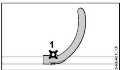
● Loosen the star knob screw (1).
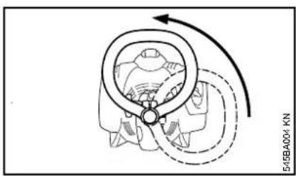
natural_image
Diagram of a mechanical component with directional arrows indicating motion (no text or symbols)Adjusting loop handle without star knob screw
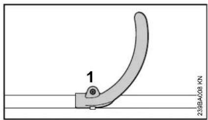
natural_image
Diagram of a mechanical component with directional arrows indicating motion (no text or symbols)natural_image
Technical line drawing of a mechanical device with no visible text or symbolsnatural_image
Line drawing of a mechanical device with a bottle and fan (no text or symbols)natural_image
Diagram of a circular device with a rotating arrow indicating rotation, no text or symbols presentADVERTENCIA
natural_image
Diagram of a mechanical component with rotational arrow indicating motion (no text or symbols)
ADVERTENCIA
natural_image
Illustration of a person using a tool on a surface, no text or symbols presentnatural_image
Illustration of two hands performing a physical maneuver on a foot, one pressing down and the other holding the foot (no text or symbols present)Intermediate = 125 horas
Moderate = 50 horas
Motor
STIHL Inc., 536 Viking Drive, P.O. Box 2015,
Virginia Beach, VA 23450-2015.
www.stihlusa.com
MasterWrench Service®
MotoMix®
OILOMATIC®
ROCK BOSS®
STIHL Cutquik®
STIHL DUROMATIC®
STIHL Quickstop®
STIHL ROLLOMATIC®
STIHL WOOD BOSS®
TIMBERSPORTS®
WOOD BOSS®
YARD BOSS®
This product contains chemicals known to the State of California to cause cancer, birth defects or other reproductive harm.

WARNING
The engine exhaust from this product contains chemicals known to the State of California to cause cancer, birth defects or other reproductive harm.
0458-545-8621-E
0458-545-8621-E

- WARNING
- ADVERTENCIA
- English
- Guide to Using this Manual
- Pictograms
- Symbols in Text
- NOTICE
- Engineering Improvements
- Safety Precautions and Working Techniques
- THE OPERATOR
- Physical Condition
- Proper Clothing
- THE POWER TOOL
- Fuel
- Fueling Instructions
- Pick a Safe Location
- Allow the Power Tool to Cool Before Removing the Fuel Cap
- Fuel Spraying or "Geysering"
- How to Avoid Fuel Spraying
- Removing the Threaded Fuel Filler Cap
- Installing the Threaded Fuel Filler Cap
- Damaged or Broken Cap
- Vapor Lock
- Before Operation
- Starting
- Important Adjustments
- During Operation
- Working Conditions
- Operating Instructions
- USING THE CUTTING ATTACHMENT
- MAINTENANCE, REPAIR AND STORING
- Preparations
- Adjusting Depth of Cut
- Edging
- Mounting the Loop Handle
- STIHL MotoMix
- Fuel mix ages
- Fueling
- Avoid Injuries from Fuel Spraying.
- Refueling
- Starting / Stopping the Engine
- Function of stop switch and ignition system
- Shut off the engine.
- Other hints on starting
- Operating Instructions Cleaning the Air Filter
- During break-in period
- After Finishing Work
- Engine Management Adjusting the Carburetor
- Adjusting Idle Speed
- Spark Plug
- Removing the Spark Plug
- Checking the spark plug
- Engine Running Behavior Storing the Machine
- Installing the Spark Plug
- Replacing the Depth Wheel
- Replacing the Skirt
- Replacing the Cutting Blade
- Checking Out-of-Balance
- Checking and Replacing the Wear Guard
- Inspections and Maintenance by Dealer
- Main Parts
- 11
- Serial Number
- Definitions
- Skirt
- Specifications
- EPA / CEPA
- CARB
- Engine
- Ignition System
- Fuel System
- Weight
- Maintenance and Repairs
- Disposal
- Limited Warranty STIHL Incorpor
- rated Federal Emission Control Warranty Statement
- Manufacturer's Warranty Coverage
- Owner's Warranty Responsibilities
- Coverage by STIHL Incorporated
- Warranty Period
- Diagnosis
- Warranty Work
- Maintenance Requirements
- Limitations
- STIHL Incorporated California Exhaust and Evaporative Emissions Control Warranty Statement
- For California only
- Your Warranty Rights and Obligations
- Manufacturer's Warranty Responsibilities
- Defects Warranty Period
- Emission Warranty Parts List
- Where to make a Claim for Warranty Service
- Trademarks
- STIHL Registered Trademarks
- STIHL
- G
- Contenido
- Motor
Brand : STIHL
Model : FC 56 C
Category : Brush cutter