
NetWave NW1 - Access Point ComNet - Free user manual and instructions
Find the device manual for free NetWave NW1 ComNet in PDF.


| Product Type | Industrial Outdoor 802.11a/n Wireless Ethernet Access Point |
| Model Number | NetWave NW1 (FCC Version, User Configurable) |
| Wireless Standard | 802.11a/n (5 GHz) |
| Maximum Throughput | Up to 95 Mbps (MIMO technology) |
| Operating Mode | Access Point or Client (user-configurable via web interface) |
| Maximum Clients | Up to 15 simultaneous clients (point-to-multipoint) |
| Antenna | Integrated directional antenna; external omni antenna support |
| Power Supply | Passive PoE (Power over Ethernet) 24 VDC via included injector |
| Power Consumption | Approximately 12 W (typical) |
| Ethernet Interface | 1x 10/100 Mbps RJ-45 (shielded CAT5 or better) |
| LED Indicators | Power, Ethernet/RSSI2, RSSI3, Status/RSSI4 |
| Web Interface Default IP | 192.168.10.101 |
| Web Interface Credentials | Username: admin / Password: admin |
| Wireless Security | WEP, WPA/WPA2-PSK, WPA2-AES, 802.1x (EAP-TTLS, EAP-PEAP) |
| Mounting | Outdoor pole mount (up to 2.5" / 65 mm diameter); optional upgrade bracket NWBKT1 |
| Environmental | Industrial hardened, wide operating temperature range |
| Certification | FCC Part 15 Class A, ICES-003, CE (ETSI version available) |
| Dimensions (Approx.) | 200 x 150 x 50 mm (without bracket) |
| Weight (Approx.) | 0.8 kg (without bracket and cables) |
| Care and Cleaning | Wipe with a dry, soft cloth. Do not use liquid cleaners. |
| Safety | Install in controlled access area; only ComNet service personnel to service. |
| Spare Parts / Repairability | Contact ComNet support for replacement parts or service. |
| General Information | Point-to-multipoint wireless bridge. Default WPA pre-shared key: 12345678. Long range support up to 4000+ m with proper configuration. |
Frequently Asked Questions - NetWave NW1 ComNet
User questions about NetWave NW1 ComNet
0 question about this device. Answer the ones you know or ask your own.
Ask a new question about this device
Download the instructions for your Access Point in PDF format for free! Find your manual NetWave NW1 - ComNet and take your electronic device back in hand. On this page are published all the documents necessary for the use of your device. NetWave NW1 by ComNet.
USER MANUAL NetWave NW1 ComNet
Communication Networks
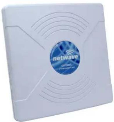
natural_image
White electronic device with 'netwave' logo and network wave design (no readable text beyond branding)INSTALLATION AND OPERATION MANUAL

INDUSTRIAL OUTDOOR 802.11A/N WIRELESS ETHERNET
This manual serves the following ComNet Model Numbers:
NW1
NW2
NWK1
NWK2
Thank you for purchasing NetWave ^® from ComNet. This installation guide applies to the following models:
NW1: Industrial Multipoint, FCC Version, User Configurable
NW2: Industrial Multipoint, ETSI Version, User Configurable
NWK1: Industrial Point to Point Kit, FCC Version (Includes NWK1_AP and NWK1_CL)
NWK2: Industrial Point to Point Kit, ETSI Version (Includes NWK2_AP and NWK2_CL)
The NetWave ^® industrially hardened wireless Ethernet transmission link from ComNet ^™ can be configured through the embedded User Interface as a Client or as an Access Point. This point-to-multipoint model allows multiple Ethernet endpoints to be connected to a central Access Point. Up to 15 endpoints can be linked to a central access point. The NW1 and NW2 support up to 95Mbps throughput using MIMO technology. An easy to read LED array displays unit operational status along with received signal strength ensuring optimal installation and operation. The units are passive powered by PoE (Power over Ethernet) through a supplied PoE injection module. The NW1 is FCC certified and the NW2 is ETSI, DFS and TPC certified.
About This Guide
This guide is intended for different users such as engineers, integrators, developers, IT managers, and technicians.
It assumes that users have some PC competence and are familiar with Microsoft Windows operating systems and web browsers such as Windows Internet Explorer and Mozilla Firefox, as well as have knowledge of the following:
»Installation of electronic equipment
»Electrical regulations and guidelines
»Knowledge of Local Area Network technology
Related Documentation
The following documentation is also available:
»NW1/NW2 and NWK1/NWK2 Datasheets
»NW1/NW2 and NWK1/NWK2 Quick Start Guides
Website
For information on ComNet's entire product line, please visit the ComNet website at http://www.comnet.net
Support
For any questions or technical assistance, please contact your sales person (sales@comnet.net) or the customer service support center (techsupport@comnet.net)
Safety
» Only ComNet service personnel can service the equipment. Please contact ComNet Technical Support.
» The equipment should be installed in locations with controlled access, or other means of security, and controlled by persons of authority.
Contents
About This Guide 2
Related Documentation 2
Website 2
Safety 2
Overview 4
Legal Information 4
1.0 Introduction 5
2.0 Point to Multi-Point - NW1 and NW2 6
3.0 Point to Point Systems - NWK1 and NW2 6
4.0 Cabling Requirements 6
5.0 Hardware Installation 7
5.1 NW1 and NW2 Outdoor Ethernet Gland Installation 7
5.2 NW1 and NW2 Indicating LED Details 9
5.3 NW1 and NW2 Outdoor Standard Mounting Hardware 10
5.4 NW1 and NW2 Outdoor Upgrade Mounting Hardware 11
6.0 Key Default Configurations 12
7.0 Quick Configuration 13
8.0 Detailed Configuration 14
8.1 STATUS Page - Access Point 14
8.2 STATUS-Client Page - Client 17
8.3 WIRELESS SETTINGS Page - Access Point 20
8.4 WIRELESS SETTINGS-Client Page - Client 25
8.5 NETWORK SETTINGS Page - Client or Access Point 29
8.6 SYSTEM TOOLS Page - Client and Access Point 31
8.7 ADMIN Page - Client or Access Point 36
10.0 Agency Compliance 41
11.0 GPL (General Public License) Statement 43
Overview
Legal Information
No part of this document may be reproduced or transmitted in any form or by any means, electronic and mechanical, for any purpose, without the express written permission of ComNet.
Copyright
Copyright © 2013 ComNet. All rights reserved.
Disclaimer
ComNet reserves the right to make changes in specifications at any time without notice. The information furnished by ComNet in this material is believed to be accurate and reliable. However, ComNet assumes no responsibility for its use.
1.0 Introduction
The NetWave® industrially hardened wireless Ethernet transmission link from ComNet™ can be configured through the embedded User Interface as a Client or as an Access Point. This point-to-multipoint model allows multiple Ethernet endpoints to be connected to a central Access Point. Up to 15 endpoints can be linked to a central access point. The NW1 and NW2 support up to 95Mbps throughput using MIMO technology. An easy to read LED array displays unit operational status along with received signal strength ensuring optimal installation and operation. The units can be powered by an IEEE 802.3af PoE compliant switch or through the supplied power injection module. The NW1 is FCC certified and the NW2 is ETSI, DFS and TPC certified.
This manual contains detailed information covering ComNet NetWave outdoor 802.11n wireless products. NetWave was designed for use in a wide ambient operating temperature range. NetWave provides a cost effective 802.11-based solution. The units come configured for either point to point or point to multipoint applications.
This manual contains detailed operational and configuration information not covered in the quick start guides.
This guide applies to the following models:
NW1 - Industrial Multipoint, FCC Version, User Configurable
NW2- Industrial Multipoint, ETSI Version, User Configurable
NWK1 - Industrial Point to Point Kit, FCC Version (Includes NWK1_AP and NWK1_CL)
NWK2 - Industrial Point to Point Kit, ETSI Version (Includes NWK2_AP and NWK2_CL)
2.0 Point to Multi-Point - NW1 and NW2
These individual units allow the user to configure for either multipoint access point or client operation. There is a MAC address lock feature that can be enabled through the user interface but is not enabled by default. The NWx supports integrated directional and external omni directional antennas. See the ComNet website for the latest information regarding antenna support.
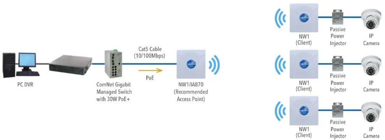
flowchart
graph LR
    A["PC DVR"] --> B["Server"]
    B --> C["ComNet Gigabit Managed Switch with 30W PoE+"]
    C --> D["Cat5 Cable (10/100Mbps)"]
    D --> E["NW1/IA870 (Recommended Access Point)"]
    E --> F["IP Camera"]
    E --> G["NW1 (Client)"]
    E --> H["NW1 (Client)"]
    E --> I["NW1 (Client)"]
    E --> J["NW1 (Client)"]
    F --> K["Passive Power Injector"]
    G --> L["Passive Power Injector"]
    H --> M["Passive Power Injector"]
    I --> N["Passive Power Injector"]
    J --> O["Passive Power Injector"]
3.0 Point to Point Systems - NWK1 and NW2
Each point to point kit comes with a preconfigured access point and client. Both units will not only be configured to operate on the same SSID but also MAC addressed locked to each other. This simplifies installations as well as enabling higher operating EIRP for FCC versions. The NetWave preconfigured kit supports integrated directional and external omni directional antennas. See the ComNet website for the latest information regarding antenna support.

flowchart
graph LR
    A["PC DVR"] --> B["Server"]
    B --> C["ComNet Gigabit Managed Switch with 30W PoE+"]
    C --> D["NW1/IA870 (Recommended Access Point)"]
    D --> E["NWK1 (Client)"]
    E --> F["Passive Power Injector"]
    F --> G["IP Camera"]
    H["Cat5 Cable (10/100Mbps)"] --> C
    I["PoE"] --> D
4.0 Cabling Requirements
Shielded CAT 5 or better should be used for all out of plant Ethernet connection and should be properly grounded through the PoE AC ground. Industrial grade shielded Ethernet cable is recommended to help prevent ESD damage commonly experienced with outdoor installations. Visit www.comnet.net/comnet-products/cables
5.0 Hardware Installation
5.1 NW1 and NW2 Outdoor Ethernet Gland Installation
There will be at least one cable gland included with each outdoor enclosure. Below is an image of the individual parts of the gland with an Ethernet cable routed through.
Note: The split rubber washer allows a pre-terminated Ethernet cable to be used.
Once the cable has been routed through the weather connection as shown, push the split rubber gasket into place and loosely screw the cap that goes over the rubber washer.
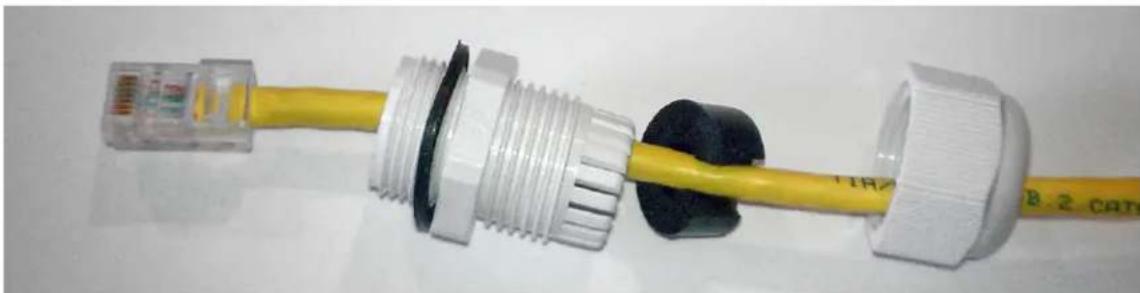
natural_image
Close-up of a yellow cable with white connectors and black plastic cap, attached to a transparent plastic connector (no text or symbols visible)Below is an image with the Ethernet connection made to the node and the gland assembly about to be installed.
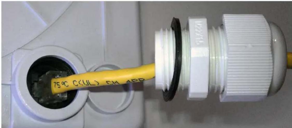
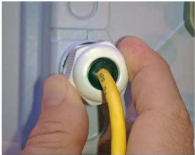
Once the RJ45 connection has been made, screw in the gland into the housing making sure it is tight enough for a water tight seal.
Once the gland is tight in the housing, tighten the outer nut/cap making sure the rubber seal squeezes and seals the Ethernet cable to the gland as shown below.
natural_image
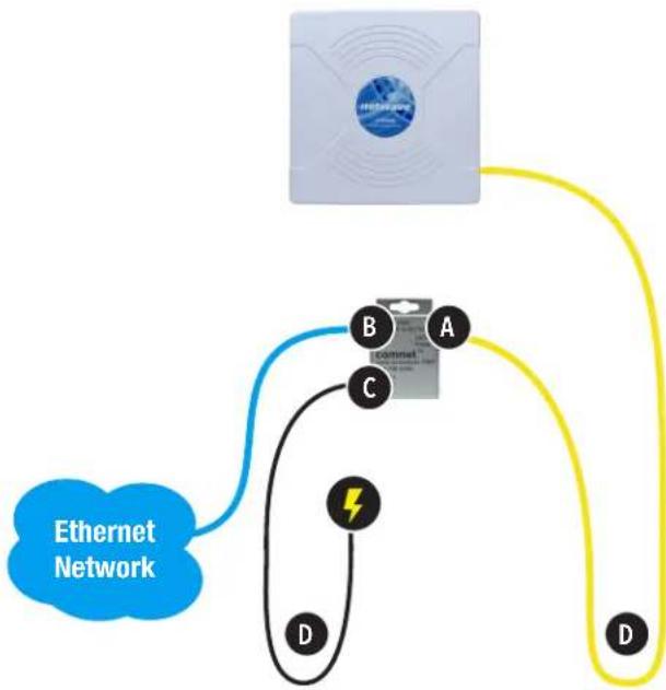
Close-up of hands inserting a yellow cable into a white plastic connector (no text or symbols visible)Connect one end of an RJ-45 Ethernet cable to the LAN OUT port of the Power Injection Module (PIM) and the other end to LAN of the access point - as sown below.
Note: Maximum length of the RJ-45 CAT5 cable is 90 meters.
Connect the RJ-45 Ethernet cable attached to the PIM to a network device, such as a switch or to the configuration PC. Then plug the power adaptor to an AC power outlet and power plug into the socket of the PIM – as shown in the diagram below.
Note: DC Passive PoE input for the NW1 and NW2 is 24 VDC.
flowchart
graph TD
    A["Router"] --> B["Router"]
    B --> C["Switch 1"]
    B --> D["Switch 2"]
    B --> E["Switch 3"]
    B --> F["Switch 4"]
    B --> G["Switch 5"]
    style B fill:#f9f,stroke:#333
    note right of B "Ethernet Network"
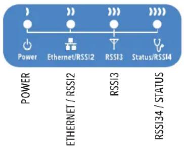
5.2 NW1 and NW2 Indicating LED Details
flowchart
graph LR
    A["Power"] --> B["Ethernet/RSSI2"]
    B --> C["RSSI3"]
    C --> D["Status/RSSI4"]
    style A fill:#fff,stroke:#000
    style B fill:#fff,stroke:#000
    style C fill:#fff,stroke:#000
    style D fill:#fff,stroke:#000
| LED VISUAL CUE INDICATION | ||
| POWER | SOLID RED Power is supplied to the NW1/NW2 | |
| OFF No power is supplied to the NW1/NW2 | ||
| ETHERNET / RSSI2 | SOLID RED Ethernet connection is established | |
| FLASH RED Ethernet connection is established and there is activity present | ||
| OFF No Ethernet connection established | ||
| RSSI3 SOLID GREEN | Good signal strength | |
| RSSI4 / STATUS | FLASH GREEN Unit is booting up | |
| SOLID GREEN Excellent signal strength | ||
SIGNAL STRENGTH:
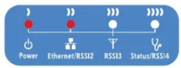
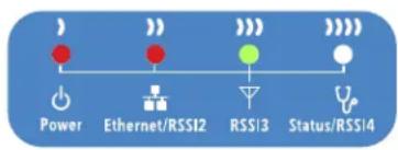
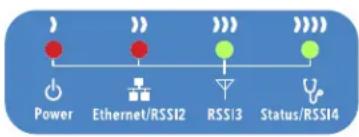
MINIMUM SIGNAL MAXIMUM SIGNAL
Power - will illuminate when there is power applied to the Ethernet port
Ethernet - will illuminate when there is an active Ethernet connection
RSSI3 – will illuminate when the RSSI threshold goes above what is set in the RSSI LED Setting section of the WIRELESS SETTINGS page
Status/RSSI4 - Provided status during boot and will illuminate solid when the RSSI threshold goes above what is set in the RSSI LED Setting section of the WIRELESS SETTINGS page
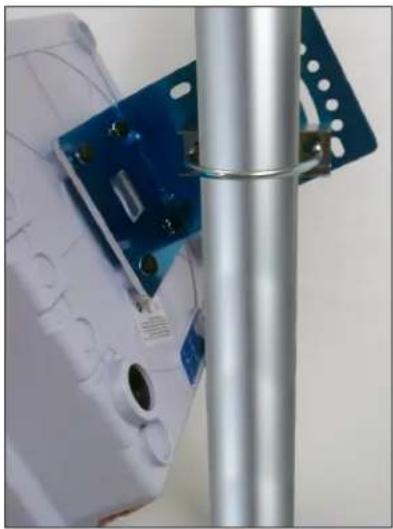
5.3 NW1 and NW2 Outdoor Standard Mounting Hardware
This mounting hardware will support pole diameters up to 2.5 inches or 65mm.
Below are the parts contained in the standard mounting hardware
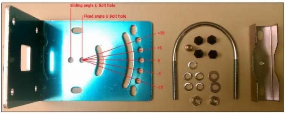
Here is the mounting hardware assembled shown in a +45° and -45° vertical position
natural_image
Close-up of a white electronic device with blue circuit board and metal bracket, no visible text or symbols
natural_image
Close-up of a white plastic panel with visible wiring and a blue plastic bracket attached to a metal pole (no text or symbols)5.4 NW1 and NW2 Outdoor Upgrade Mounting Hardware
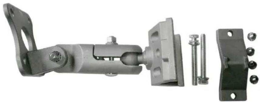
An upgrade to the outdoor mounting hardware is available. This optional version is of heavier construction supporting an articulating joint and is designed for wall or pole mount supporting up to a 3 inch or 76mm pole.
Note: This hardware is sold separately under part number NWBKT1
natural_image
Mechanical assembly diagram showing a linkage mechanism with bolts and mounting bracket (no text or symbols)6.0 Key Default Configurations
IP Address of Web Server 192.168.10.100 for NWK x_AP 192.168.10.101 for all other models
LAN Mode for Web Server Static Addressing
Web Server User ID admin
Web Server Password admin
WPA Pre-shared Key 12345678
Channel-Frequency (AP) Auto
Channel Spectrum Width 20/40M
Long Range Parameters Enabled and defaulted to 1000m
Note: A Reset to defaults (performed on the ADMIN page) will erase all user configurations including the factory set MAC lock on Point to Point (NWKx) models.
7.0 Quick Configuration
- Connect an Ethernet cable from the port labelled as IN on the power Injection Module to either a laptop or a PC LAN port.
- Connect the second Ethernet cable from the OUT port on the Power Injection Module to the NetWave LAN port.
- Apply 24VDC to the Power Injection Module with the provided power supply. You should notice the green LED illuminate in the Power Injection Module and the power LED on the NetWave unit.
- Set the IP address of the laptop being used to configure NetWave to static and the subnet to 192.168.10.x /24 subnet.
-
Point the browser to 192.168.10.101. This is the default address.
-
A login prompt will pop up. Enter:
ID admin
Password admin
- Select the NETWORK SETTINGS tab and set the desired network settings.
Select Apply Settings
Select Save
Note: This will be the network address for the NetWave web server. It is not necessary to set to the same subnet as the operating network but it is recommended.
-
Select the WIRELESS SETTINGS tab and set:
-
Wireless mode - Set to AP or Client (Only need to do this on the NW1 and NW1 models)
- Country code - Only required if setting up the NW2 (ETSI) model
Note: It is the user's responsibility to ensure that the correct country is chosen. ComNet accepts no liability for incorrect equipment set up. - Output RF power - if RSSI is greater than 70, it is recommended to reduce RF TX power.
- Set SSID - if changing from the default setting
- Channel Spectrum Width - May want to reduce to 20M from the default 20/40M if the 5GHz spectrum is crowded
- Wireless Security - if changing from default settings
- Select Apply Settings
- Select Save
Note: NWKx point to point kits have been set up at the factory and locked to each other. No need to set Wireless Mode and may not need to set the IP address. These are designed to connect to each other once powered and properly aligned.
Note: NW1 and NW2 Multipoint nodes will need to have the Wireless Mode set to either AP or Client (default is Client). And the IP addresses will need to be all set to different addresses (default address is 192.168.10.101). Once this is done, all the clients will connect to the multipoint AP with all other setting kept at default.
8.0 Detailed Configuration
8.1 STATUS Page - Access Point
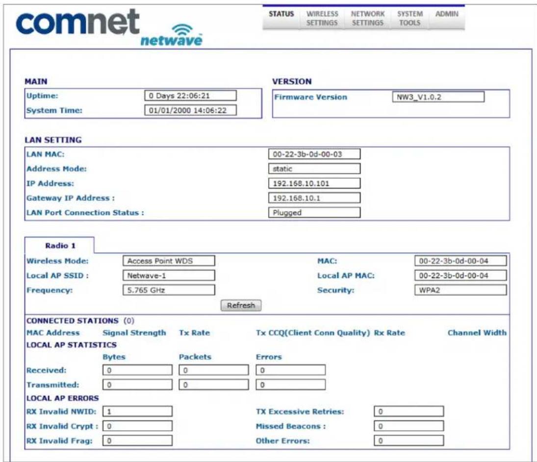
8.1.1 STATUS\_AP Page MAIN Section
This section will list the unit uptime as well as the system time which can be set on the SYSTEM TOOLS page.
8.1.2 STATUS\_AP Page LAN SETTING Section
LAN MAC Lists the MAC address for the electrical copper Ethernet port
Address Mode Shows the current setting for setting the IP address for the embedded web server. This is configured on the NETWORK SETTINGS page
IP Address Current IP address for the embedded web server
Gateway IP Address IP address for the network gateway
LAN Port Connection Shows connection status for the copper Ethernet port.
8.1.3 STATUS\_AP Page RADIO Section
Wireless Mode Shows the operational mode for the radio. This can be set on the WIRELESS SETTINGS page.
Local AP SSID SSID that this AP is broadcasting.
Frequency Frequency that the AP is operating on
MAC MAC address of the AP radio
Local AP MAC MAC address of the AP radio
Security Operating security. This can be selected on the WIRELESS SETTINGS page
8.1.4 STATUS\_AP Page CONNECTED STATIONS Section
MAC Address Lists the MAC addresses of the connected stations
Signal Strength Lists the RSSI values of the connected stations
Tx Rate will show the transmit radio connection rate
TX CCQ Client Connection Quality. Given in % and provide the radio connection quality with the connected AP with 100% being the best.
| Channel Width | channel width the radio connection is using. This is automatically determined based on the radio connection quality when 20/40M channel bandwidth is selected on the WIRELESS SETTINGS page. Possible connections that may be displayed are listed below starting with the best/fastest connectionHT40+HT40HT40-HT20HT10 |
Refresh Button This will cause the data that feeds this page to be refreshed.
8.1.5 STATUS\_AP Page LOCAL AP ERRORS Section
| RX Invalid NWID Shows the number of SSIDs detected that is different from the Remote AP SSID. This number will continually count up and will count up faster in congested RF environments. It is normal to see this count increase. | |
| RX Invalid Crypt Represents the number of transmitted and received packets which were encrypted with the wrong encryption key and failed the decryption routines. It can be used to detect invalid wireless security settings and encryption break attempts. | |
| RX Invalid Frags This value represents dropped packets due to packet reassembly failure due to link layer fragments. | |
| TX Excessive Retries | Represents the number of packet delivery failures. Undelivered packets are retransmitted a set number of times before an error is logged and counted. |
| Missed Beacons Beacons are management packets sent by an AP and this value represents the number of beacons which were not received by the client. Missed Beacon counts could indicate that there is too much distance between the Client and AP. | |
| Other Errors This count represents the total number of transmitted and received packets that were lost or discarded for reasons other than what is listed above. | |
8.2 STATUS-Client Page - Client
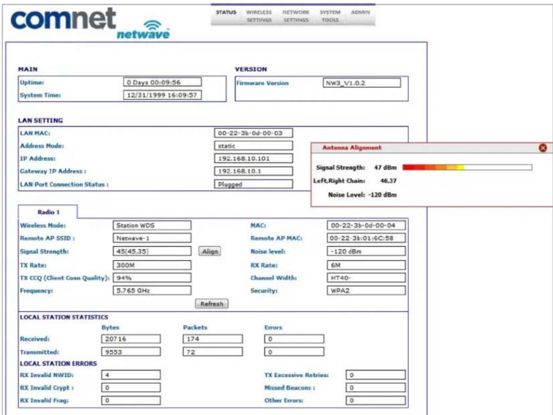
8.2.1 STATUS-Client Page MAIN Section
This section will list the unit uptime as well as the system time which can be set on the SYSTEM TOOLS page.
8.2.2 STATUS-Client Page LAN SETTING Section
| LAN MAC Lists the MAC address for the electrical copper Ethernet port | |
| Address Mode Shows the current setting for setting the IP address for the embedded web server. This is configured on the NETWORK SETTINGS page | |
| IP Address Current IP address for the embedded web server | |
| Gateway IP Address | IP address for the network gateway |
| LAN Port Connection | Shows connection status for the copper Ethernet port. |
8.2.3 STATUS-Client Page RADIO Section
Wireless Mode Lists the operational mode for the radio. This can be set on the WIRELESS SETTINGS page.
Remote AP SSID SSID for that the client will scan and connect to.
Noise Level Receiver noise floor. A higher number indicates an operating environment with more RF noise/congestion.
Signal Strength Received signal strength.
TX Rate Radio connect rate for the transmit portion
RX Rate Radio connect rate for the receive portion
TX CCQ Client Connection Quality. Given in % and provide the radio connection quality with the connected AP with 100% being the best.
Frequency Frequency the client is using to connect to the AP
MAC MAC address of the client radio
Remote AP MAC MAC address of the connected AP radio
Channel Width channel width the radio connection is using. This is automatically determined based on the radio connection quality when 20/40M channel bandwidth is selected on the WIRELESS SETTINGS page. Possible connections that may be displayed are listed below starting with the best/fastest connection HT40+ HT40 HT40- HT20 HT10
Security Operating security. This can be selected on the WIRELESS SETTINGS page
Align Button This will produce a pop up Antenna Alignment window (shown below) that will render a graphical RSSI meter. This meter will present a scale between 0 and 100. This tool may be helpful when performing antenna alignments.
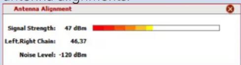
NOTE: RSSI values above 70 will begin to cause reduction of link throughput. RSSI values greater than 75 will significantly reduce link throughput but RSSI values this high are normally experienced during bench testing.
Refresh Button This will cause the data that feeds this page to be refreshed.
8.2.4 STATUS-Client Page LOCAL STATION STATICS Section
Received Shows Bytes, Packets, and Errors received
Transmitted Shows Bytes, Packets, and Errors transmitted
8.2.5 STATUS-Client Page LOCAL STATION ERROR Section
| RX Invalid NWID Shows the number of SSIDs detected that is different from the Remote AP SSID. This number will continually count up and will count up faster in congested RF environments. It is normal to see this count increase. | |
| RX Invalid Crypt Represents the number of transmitted and received packets which were encrypted with the wrong encryption key and failed the decryption routines. It can be used to detect invalid wireless security settings and encryption break attempts. | |
| RX Invalid Frags This value represents dropped packets due to packet reassembly failure due to link layer fragments. | |
| TX Excessive Retries | Represents the number of packet delivery failures. Undelivered packets are retransmitted a set number of times before an error is logged and counted. |
| Missed Beacons Beacons are management packets sent by an AP and this value represents the number of beacons which were not received by the client. Missed Beacon counts could indicate that there is too much distance between the Client and AP. | |
| Other Errors This count represents the total number of transmitted and received packets that were lost or discarded for reasons other than what is listed above. | |
8.3 WIRELESS SETTINGS Page - Access Point
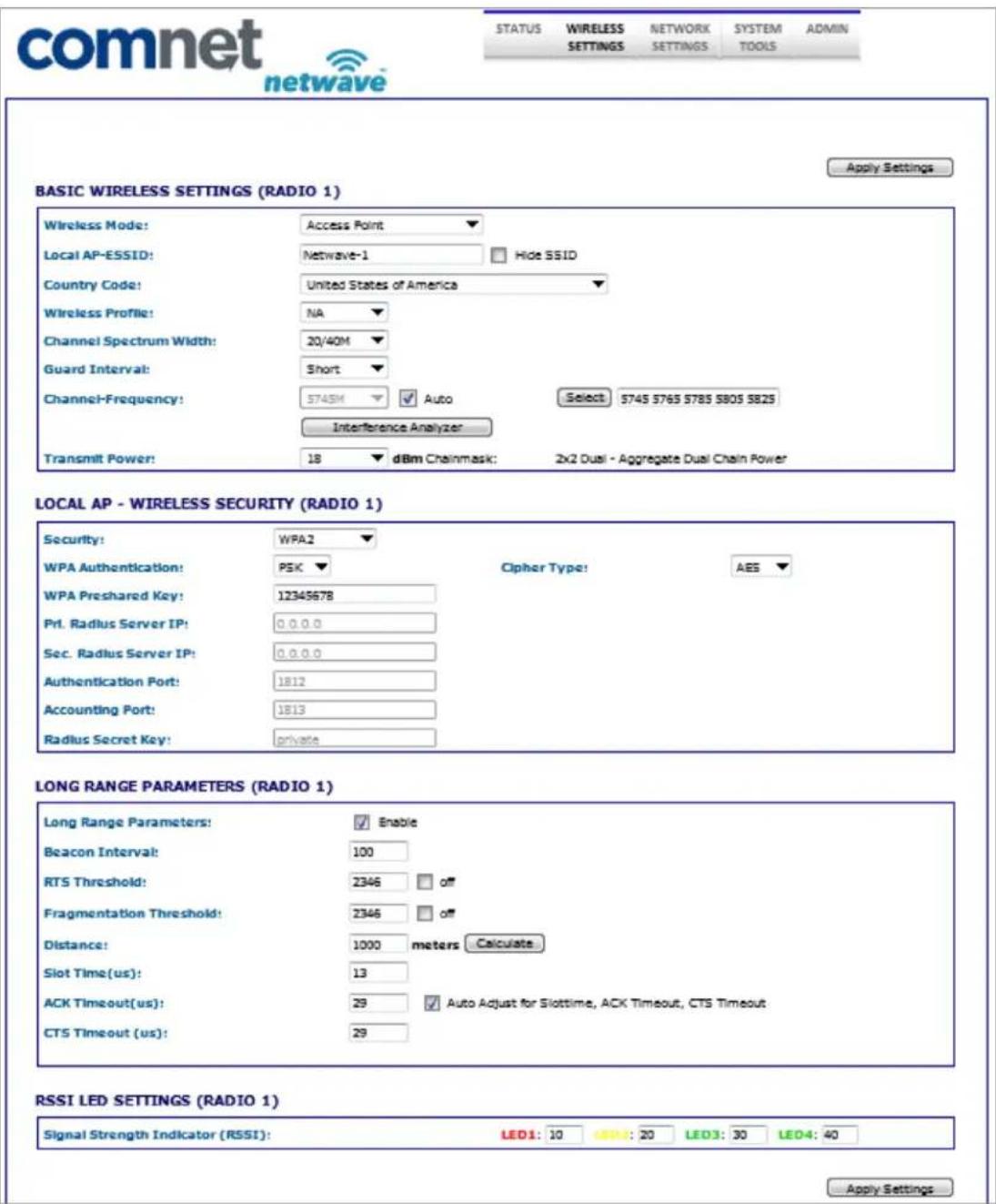
8.3.1 WIRELESS SETTINGS-AP Page BASIC WIRELESS SETTINGS Section
Note: Any settings changes made on this page will require the hitting Apply Settings button then Select Save.
Wireless Mode The user can select either Access Point or Client mode of operation.
Local AP-ESSID The SSID this AP will broadcast.
Country Code A country of operation can be selected from the pull down.
NOTE: For the FCC version, only United States will be in the list while countries participating in the ETSI harmonized standards will populate this list for the ETSI version.
Wireless Profile Select either NA or NG operation. NA is 802.11a and 802.11n (5GHz operation). NG is 802.11g and 802.11n (2.4GHz operation).
NOTE: Some models may only support the NA (5GHz) option.
| Channel Spectrum Width | The user can select the operation channel width. 20/40M lets the units determine the best channel width with the maximum 40MHz as an option under good RF conditions. One may want to choose 20MHz for noisy or congested RF environments. Options available are 20/40M, 20M, and 10M. |
Guard Interval This represents the guard interval between packets. The options are Short and Long. The Long option is recommended for links greater than 2Km in distance.
| Channel Frequency | Auto is enabled by default. When Auto is unchecked, the user can select from a number of frequencies available from the drop down list. When Auto is checked and during boot up, the AP will select the operational channel with least interference. |
Select Button When pressed, a pop up screen comes up like the one below:
5745 MHz 5765 MHz 5785 MHz 5805 MHz 5825 MHz
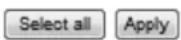

This allows the user to select which frequencies the AP will scan for during reboot and when Auto mode is checked/enabled.
Interference Analyzer Button
When pressed, will generate a pop up window showing all the detected AP signals like the image below:

bar
Channel Bandwidth: 2040M Scan Channels: $745 5765 5785 5805 5825 Frequency Interference | Frequency | Interference | | :--- | :--- | | 5180 | 0 | | 5200 | 0 | | 5220 | 0 | | 5240 | 0 | | 5260 | 0 | | 5280 | 0 | | 5300 | 0 | | 5320 | 0 | | 5500 | 0 | | 5520 | 0 | | 5540 | 0 | | 5560 | 0 | | 5580 | 0 | | 5600 | 0 | | 5620 | 0 | | 5640 | 0 | | 5660 | 0 | | 5680 | 0 | | 5700 | 0 | | 5745 | 40 | | 5765 | 68 | | 5785 | 71 | | 5805 | 74 | | 5825 | 68 | Close this window.Transmit Power This section will set the RF transmit power. The maximum RF power available will be limited in software based on the gain of the integrated antenna and the region the unit was programmed to operate in. The default will set the unit to maximum allowed RF power. Here the user can reduce the RF power in case the RX RSSI levels on the remote unit exceed 65.
Remember to select Apply Settings if any changes were made.
8.3.2 WIRELESS SETTINGS-AP Page WIRELESS SECURITY Section
| Security Here the end user can select the wireless security mode. Options available are None, WEP, WPA, WPA2, and 802.1x port-based security. 802.1x is for secure user-based authentication through a centralized authentication server. | |
| WPA Authentication | Options here will set the authentication depending on the security selected above. PSK (Pre-Shared Key) is the default for WPA/WPA2 security. EAP-TTLS and EAP-PEAP are the two authentication methods for 802.1x security. NOTE: Operating with 802.1x security will limit link throughput to a maximum of 54Mbps. |
| Cipher Type Options for WPA/WPA2 are TKIP (Temporal Key Integrity Protocol) which uses the RC4 encryption algorithm and AES (Advanced Encryption Standard). AES is the default setting and is the recommended cipher allowing the highest link throughput. TKIP will limit throughput to a maximum of 54Mbps. | |
Remember to select Apply Settings if any changes were made.
Pre-shared Key (For use with WPA security) Here an alpha-numeric between 8 and 63 character long pre-shared key can be entered.
Identity (For use with 802.1x security) identification credential and be entered here to be used by the WPA supplicant for EAP authentication.
User Name (For use with 802.1x security) Identification credential used by the APA supplicant for EAP - tunnelled authentication in an unencrypted form.
User Password (For use with 802.1x security) Password credential used by the WPA supplicant for EAP authentication.
Remember to select Apply Settings if any changes were made.
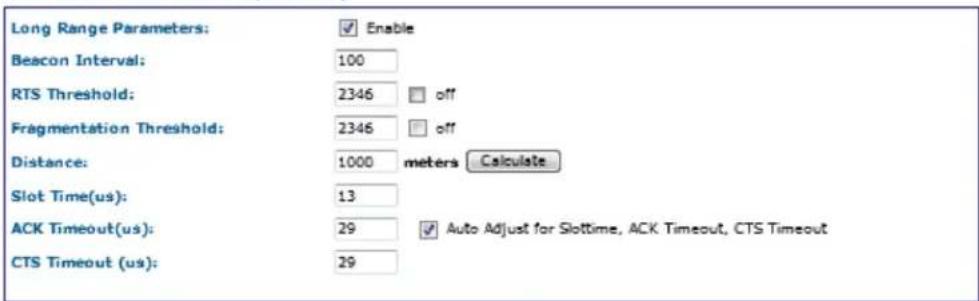
8.3.3 WIRELESS SETTINGS-AP Page LONG RANGE PARAMETERS Section
| Long Range Parameters | Check box to enable long range parameters. This is enabled and set to 1000m by default. 1000m should meet a majority of the system link distances but if the link distance goes beyond 1000m, this section will need to be adjusted on both ends of the link - see Distance and the Calculate Button section below. |
| Beacon interval | Defines the time interval (in ms) between AP beacon broadcasts. Not recommended to change the default 100ms setting. |
| RTS Threshold | RTS (Request to Send) threshold. This parameter controls what size data packet the low level RF protocol issues to an RTS packet. The default is 2346 with the valid range of 0-2346.There are several trade-offs to consider setting this parameter. Using a small value causes RTS packets to be sent more often, consuming more of the available bandwidth potentially reducing the throughput of the network packet. However, the more RTS packets that are sent, the quicker the system can recover from interference or collisions -- as would be the case in a wireless network with interference. |
| Fragmentation Threshold | Default is 2346 with a valid range is 256-2346. This parameter sets the threshold where the wireless transmission will fragment any packet if the packet size exceeds the threshold value. This setting/rule will not apply to broadcast and multicast packets. |
| Distance and the Calculate Button | Distance in meters that will be used to calculate Slot time, ACK timeout and CTS timeout. The default is 1000 meters but this value should be increased if the link distance goes beyond 1000m. Settings above 4000m will gradually start to affect link throughput. Once the distance value has been entered, press the Calculate button. This will update the Slot time, ACK Timeout, and CTS Timeout fields. Once these have been updated, press the Apply Settings button. |
Remember to select Apply Settings if any changes were made.
8.3.4 WIRELESS SETTINGS-AP Page RSSI LED INDICATOR Section
This section allows the user to set the LED threshold for the RSSI Indicating LEDs.
Note: LED1 on this page is not brought out on the external LED label, LED2 corresponds to Ethernet/RSSI2 on the LED label, LED3 corresponds to RSSI3, and LED4 corresponds to Status/RSSI4.
Remember to select Apply Settings if any changes were made.
8.4 WIRELESS SETTINGS-Client Page - Client
comnet

| STATUS | WIRELESS SETTINGS | NETWORK SETTINGS | SYSTEM TOOLS | ADMIN |
Apply Settings
BASIC WIRELESS SETTINGS (RADIO 1)
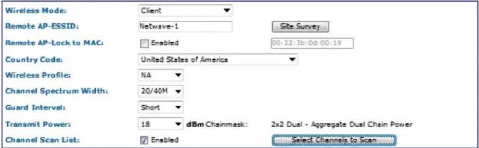
REMOTE AP - WIRELESS SECURITY:
LONG RANGE PARAMETERS (RADIO 1)
RSSI LED SETTINGS (RADIO 1)
| Signal Strength Indicator (RSSI): | LED1: 10 | LED2: 20 | LED3: 30 | LED4: 40 |
Apply Settings
8.4.1 WIRELESS SETTINGS-Client Page BASIC WIRELESS SETTINGS Section
Note: Any settings changes made on this page will require selecting the 'Save' pop up button then the 'Apply Settings' button.
Wireless Mode The user can select either Access Point or Client mode of operation.
Remote AP-ESSID Remote Access point SSID can be entered here.
Site Survey Button When pressed, will generate a pop up screen showing all the potential APs that it can connect to like the image below:
Scanned channels: 5745 5765 5785 5805 5825
| MAC address | ESSID | Encryption | ALG | Signal, dBm | Channel | Frequency |
| 00:22:3b:0d:00:19 | Netwave-1 | WPA2-PSK | AES | 40 | 149 | 5745 |
| 00:22:3b:01:6c:58 | Netwave-1 | WPA2-PSK | AES | 30 | 153 | 5765 |
| 00:22:3b:01:6c:59 | Netwave-Eng2 | WPA2-PSK | AES | 67 | 161 | 5805 |

NOTE: If there is an AP you wish to connect to, just double click on the desired AP line this window will close and auto populate the Remote AP-SSID box and the Remote AP-Lock to MAC address box.
Country Code A country of operation can be selected from the pull down.
NOTE: for the FCC version, only United States will be in the list while countries participating in the ETSI harmonized standards will populate this list for the ETSI version.
Wireless Profile Select either NA or NG operation. NA is 802.11a and 802.11n (5GHz operation). NG is 802.11g and 802.11n (2.4GHz operation). NOTE - some models may only support the NA (5GHz) option.
Channel Spectrum Width The user can select the operation channel width. 20/40M lets the units determine the best channel width with the maximum 40MHz as an option under good RF conditions. One may want to choose 20MHz for noisy or congested RF environments. Options available are 20/40M, 20M, and 10M.
Guard Interval This represents the guard interval between packets. The options are Short and Long. The Long option is recommended for links greater than 2Km in distance.
Transmit Power This section will set the RF transmit power. The maximum RF power available will be limited in software based on the gain of the integrated antenna and the region the unit was programmed to operate in. The default will set the unit to maximum RF power and here the user can reduce the RF power in case the RX RSSI levels on the remote unit exceed 65.
Channel Scan List When enabled, the client will only scan the channels selected.
Select Channels When this button is pressed, a new client scan window will pop up shown below:
5745 MHz 5765 MHz 5785 MHz 5805 MHz 5825 MHz
Select all
Clean all
Apply
Close this window
Here the user can select which channels the client will scan. This can reduce link lock times if the desired AP is fixed to a known frequency.
Remember to select Apply Settings if any changes were made.
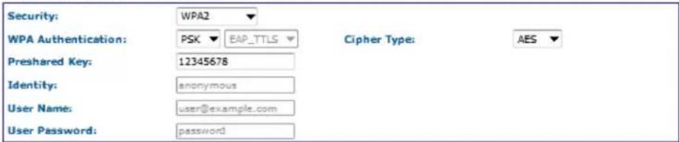
8.4.2 WIRELESS SETTINGS-Client Page WIRELESS SECURITY Section
| Security Here the end user can select the wireless security mode. Options available are None, WEP, WPA, WPA2, and 802.1x port-based security. 802.1x is for secure user-based authentication through a centralized authentication server. | |
| WPA Authentication | Options here will set the authentication depending on the security selected above. PSK (Pre-Shared Key) is the default for WPA/WPA2 security. EAP-TTLS and EAP-PEAP are the two authentication methods for 802.1x security.Note: Operating with 802.1x security will limit link throughput to a maximum of 54Mbps. |
| Cipher Type Options for WPA/WPA2 are TKIP (Temporal Key Integrity Protocol) which uses the RC4 encryption algorithm and AES (Advanced Encryption Standard). AES is the default setting and is the recommended cipher allowing the highest link throughput. TKIP will limit throughput to a maximum of 54Mbps. | |
Remember to select Apply Settings if any changes were made.
| Pre-shared Key (For use with WPA security) Here an alpha-numeric between 8 and 63 character long pre-shared key can be entered. |
| Identity (For use with 802.1x security) identification credential and be entered here to be used by the WPA supplicant for EAP authentication. |
| User Name (For use with 802.1x security) Identification credential used by the APA supplicant for EAP - tunnelled authentication in an unencrypted form. |
| User Password (For use with 802.1x security) Password credential used by the WPA supplicant for EAP authentication. |
Remember to select Apply Settings if any changes were made.
8.4.3 WIRELESS SETTINGS-Client Page LONG RANGE PARAMETERS Section
| Long Range Parameters | Check box to enable long range parameters. This is enabled and set to 1000m by default. 1000m should meet a majority of the system link distances but if the link distance goes beyond 1000m, this section will need to be adjusted on both ends of the link - see Distance and the Calculate Button section below. |
| Beacon interval | Defines the time interval (in ms) between AP beacon broadcasts. Not recommended to change the default 100ms setting. |
| RTS Threshold | RTS (Request to Send) threshold. This parameter controls what size data packet the low level RF protocol issues to an RTS packet. The default is 2346 with the valid range of 0-2346.There are several trade-offs to consider setting this parameter. Using a small value causes RTS packets to be sent more often, consuming more of the available bandwidth potentially reducing the throughput of the network packet. However, the more RTS packets that are sent, the quicker the system can recover from interference or collisions -- as would be the case in a wireless network with interference. |
| Fragmentation Threshold | Default is 2346 with a valid range is 256-2346. This parameter sets the threshold where the wireless transmission will fragment any give packet if the packet size exceeds the threshold value. This setting/rule will not apply to broadcast and multicast packets. |
| Distance and the Calculate Button | Distance in meters that will be used to calculate Slot time, ACK timeout and CTS timeout. The default is 1000 meters but this value should be increased if the link distance goes beyond 1000m. Settings above 4000m will gradually start to affect link throughput. Once the distance value has been entered, press the Calculate button. This will update the Slot time, ACK Timeout, and CTS Timeout fields. Once these have been updated, press the Apply Settings button. |
Remember to select Apply Settings if any changes were made.
8.4.4 WIRELESS SETTINGS-Client Page RSSI LED INDICATOR Section
This section allows the user to set the LED threshold for the RSSI Indicating LEDs.
Note: LED1 on this page is not brought out on the external LED label, LED2 corresponds to Ethernet/RSSI2 on the LED label, LED3 corresponds to RSSI3, and LED4 corresponds to Status/RSSI4.
Remember to select Apply Settings if any changes were made.
8.5 NETWORK SETTINGS Page - Client or Access Point
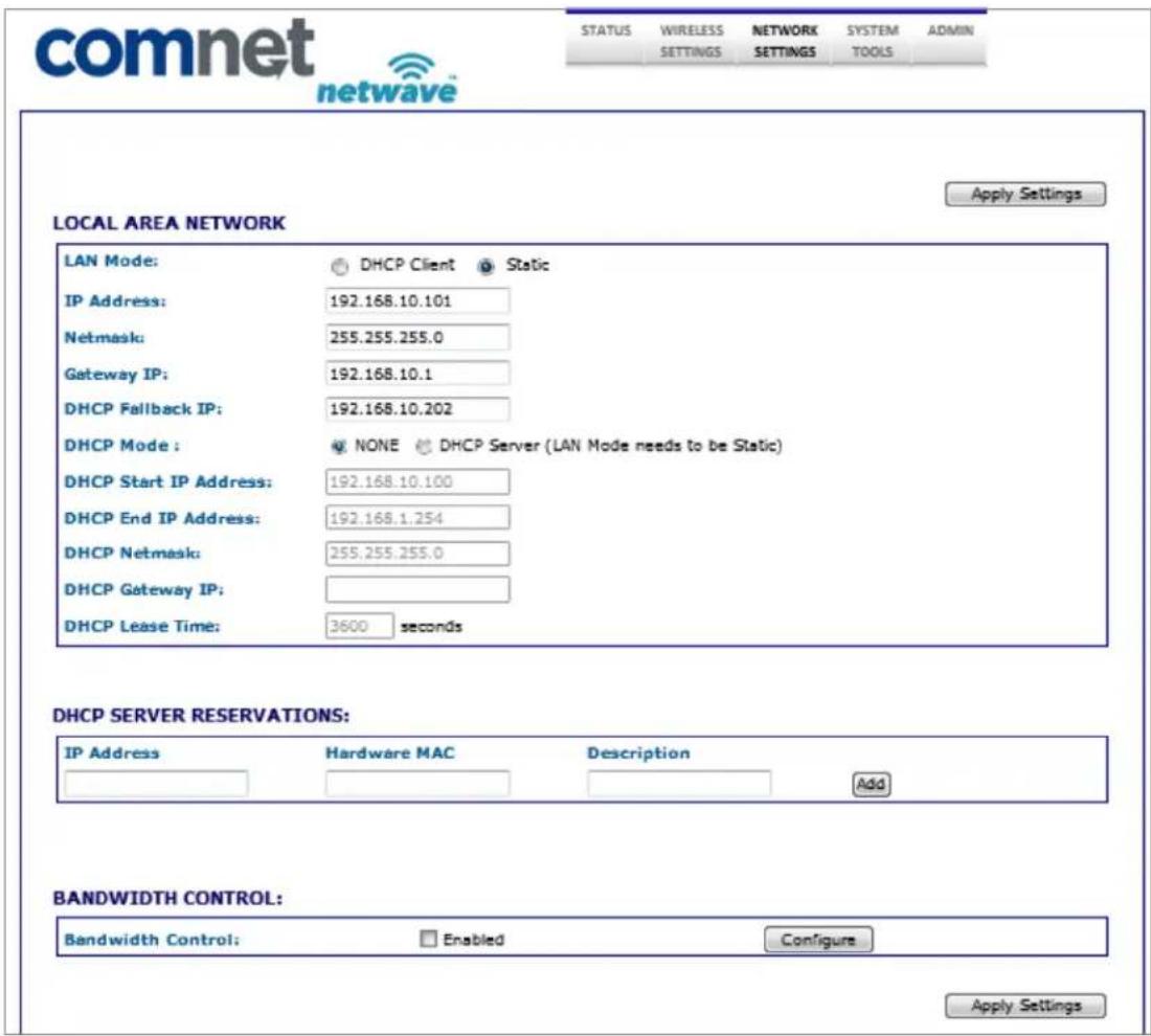
8.5.1 NETWORK SETTINGS Page LOCAL AREA NETWORK Section
| LAN Mode Embedded web server addressing mode. Options are static or dynamic for an address from a local DHCP server. | |
| IP Address For setting the static address for the embedded web server. | |
| Netmask Static network mask | |
| Gateway IP Static gateway IP address | |
| DHCP Fallback IP This will be the address the web server will default to if it cannot establish communications with a DHCP server | |
| DHCP Mode This enables an option to make the node act as a DHCP server. Note: Can only set DHCP server if the node is statically addressed. Once the DHCP Server option has been selected, DHCP option fields below are enabled for entry. | |
| DHCP Start IP DHCP address block start addressAddress | |
| DHCP Stop IP Address | DHCP address block stop address |
| DHCP Netmask | DHCP Network mask that the DHCP sever will pass to the DHCP clients |
| DHCP Gateway | IP address for the network segment gateway that the DHCP sever will pass to the DHCP clients |
| DHCP Lease Times | Lease time for the DHCP addresses. Default is 1 hour or 3600 seconds. |
Remember to select Apply Settings if any changes were made.
8.5.2 NETWORK SETTINGS Page DHCP SERVER RESERVATIONS Section
Here one can assign IP addresses to specific MAC addresses. Once the IP address and MAC address has been entered, click the ADD button. Make sure the IP address assigned is within the DHCP start and end address block.
Remember to select Apply Settings if any changes were made.
8.5.3 NETWORK SETTINGS Page BANDWIDTH CONTROL Section
When enabled is checked, this will limit up and download speeds specified by the page that will launch when the configure button is pressed as shown below:
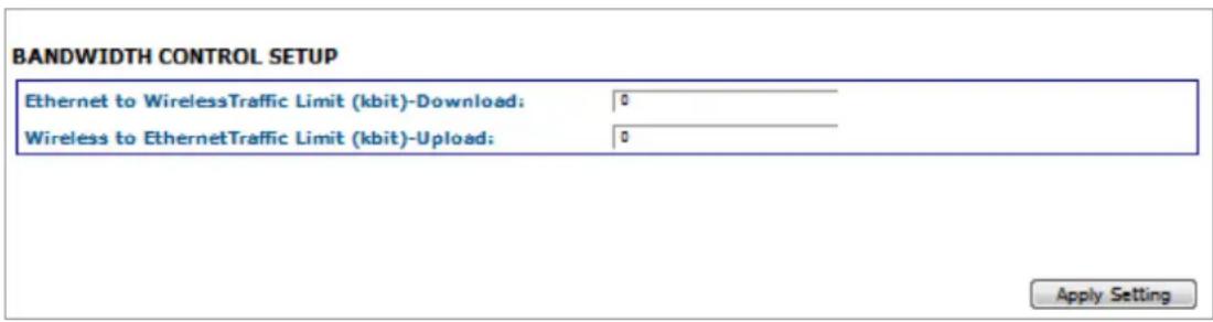
Enter in the throughput limiting values for upload and download then hit the Apply Setting button. This feature could be useful when configuring clients connecting to a single multipoint AP or in a repeating system thus keeping within the maximum throughput of any one hop or multipoint AP.
8.6 SYSTEM TOOLS Page - Client and Access Point

| STATUS | WIRELESS SETTINGS | NETWORK SETTINGS | SYSTEM TOOLS | VLAN SETTINGS | ADMIN |
SPANNING TREE PROTOCOL (STP) SETUP
| Enable STP: | |
| Root Priority: | 32768 (Range : 0 to 65536) |
| Root Hello Time: | 1 (Range : 1 to 10) |
| Root Forward Delay: | 8 (Range : 4 to 30) |
| Root Maximum Age: | 7 (Range : 6 to 40) |
| Apply |
DIAGNOSTIC TOOLS
| Throughput Test: | Launch Window |
| Throughput Monitor: | Launch Window |
| Ping Utility: | Launch Window |
| Bridge Table: | Launch Window |
| DHCP Active Leases: | Launch Window |
| ARP Table: | Launch Window |
PING WATCHDOG
| Enable Ping Watchdog: | |
| IP Address To Ping: | 192.168.10.1 |
| Ping Interval: | 5 seconds |
| Startup Delay: | 60 seconds |
| Failure Count To Reboot: | 5 |
| Apply |
AUTO-REBOOT
| Auto Reboot Mode: | Disabled |
| Apply |
SNMP SETUP
| Enable SNMP: | |
| Read Password: | public |
| Write Password: | private |
| Engine ID: | 800007e5BC0000270e000 |
| Enable SNMP Trap: | |
| Trap Destination IP: | 192.168.10.1 |
| Community: | public |
| Apply |
NTP SETUP
| Select Your Time Zone: | GMT-07:00 (Mountain Time (US & Canada), ...) | |
| Current Router Time: | 01/06/2000 15:15:21 | GMT-07:00 |
| Proposed Router Time: | 12/29/2014 10:38:11 | Adjust |
| Enable NTP Client: | ||
| Known Time Server: | bonehed.ics.mit.edu | |
| Time Server: | time.nst.gov | |
| Apply | ||
TELNET SERVER
| Enable Telnet Server: | ✓ |
| Server Port: | 23 |
| Apply |
SYSTEM LOG
| Enable System Log: | |
| Logging IP/Domain Name: | 192.168.10.1 |
| Logging Port: | 514 |
| Apply |
8.6.1 SYSTEM TOOLS Page STP Section
| Enable STP Not enabled by default | |
| Root Priority Allows the user to set priorities in each node used during the root bridge selection process. | |
| Root Hello Timer For setting STP hello times. Default is 2 | |
| Root Forward For setting STP forward delay. Default is 15 Delay | |
| Root Max Age For setting STP maximum age timer. Default is 20 |
Remember to select Apply if any changes were made.
8.6.2 SYSTEM TOOLS Page PING WATCHDOG Section
The ping watchdog utility can be a useful tool if a node needs to be periodically rebooted. Wireless equipment can sometimes require reboot to re-establish a connection if operating in noisy environments
| Enable Ping Watchdog | Not enabled by default. |
| IP Address to ping | Network address that the watchdog utility will ping. |
| Ping Interval Interval in seconds that the watchdog utility will send ICMP ping requests out. Default is 5 seconds | |
| Startup Delay One time delay after node is booted. Default is 60 seconds. | |
| Failure Count to Reboot | The number of successive ping failures before the node will initiate a reboot. |
Remember to select Apply if any changes were made.
8.6.3 SYSTEM TOOLS Page AUTO-REBOOT Section
This can bet set to reboot a certain time every day or by a set number of hours. This is disabled by default.
Remember to select Apply if any changes were made.
8.6.4 SYSTEM TOOLS Page SNMP SETUP Section
Enable SNMP Not enabled by default
Read Password Password to query the device
Engine ID Engine ID for the SNMP agent. Default is 800007e5BD00002704D000007c
Enable SNMP trap Not enabled by default.
Trap Destination IP Destination IP address where the trap messages will be sent.
Community Enter the SNMP community string
Remember to select Apply if any changes were made.
8.6.5 SYSTEM TOOLS Page NTP SETUP Section
Select your Time Zone:
| Current Router Time | This is the time the node is set to. This will be updated and displayed in the STATUS page by either setting to the browsing computer system clock or by a connected NTP server. |
| Proposed Router Time | This will display the system clock of the device that is browsing to the node. If the Adjust button is pressed, The time displayed in this box will overwrite the clock on the device. |
| Enable NTP Client not enabled by default. | |
| Known Time Server | Select a time server from the drop down list. Note: The node will need to have access to the internet to connect to any one of these servers. |
| Time server Manually enter in a time server if the desired one is not in the Known Timer Server list. | |
Remember to select Apply if any changes were made.
8.6.6 SYSTEM TOOLS Page TELNET SERVER Section
Enable Telnet Server Enabled by default
Telnet server port Port 23 is the default
8.6.7 SYSTEM TOOLS Page SYSTEM SERVER Section
| Enable Syslog Not enabled by default | |
| Logging IP/Domain Name | Enter in the destination IP address of the device to receive the system log |
| Logging port | Port 514 is the default. Port 514 is common for receiving UDP system logs |
8.6.8 SYSTEM TOOLS Page Diagnostic Tools Section
DIAGNOSTIC TOOLS
| Throughput Test: | Launch Window |
| Throughput Monitor: | Launch Window |
| Ping Utility: | Launch Window |
| Bridge Table: | Launch Window |
| DHCP Active Leases: | Launch Window |
| ARP Table: | Launch Window |
Throughput Test
Throughput Test can measure throughput between radios.
Enter the IP address of the remote device and pre Measure Throughput.
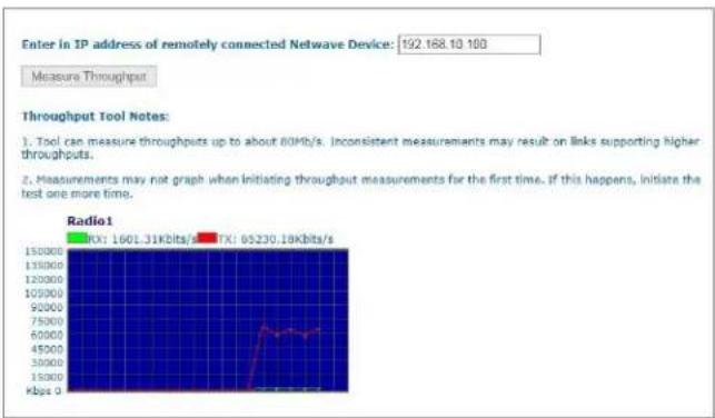
Throughput Monitor
Displays currently used throughput used by the Ethernet Port and Wireless Radio.
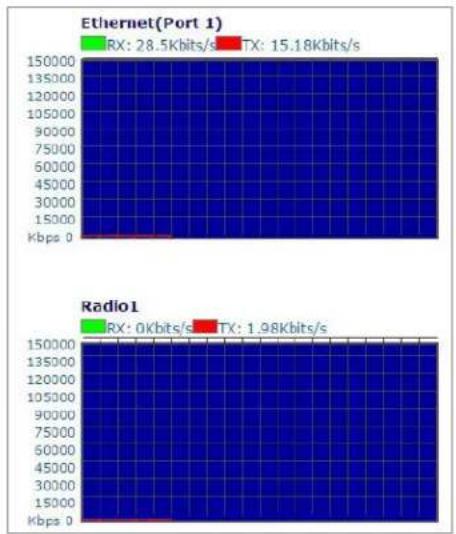
line
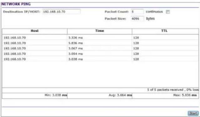
| Provider | RX (Kbits/s) | TX (Kbits/s) | | ------------ | ------------ | ------------ | | Ethernet(Port 1) | 28.5 | 15.18 | | Radio1 | 0 | 1.98 |Ping Utility
Use this utility to test network connections using ICMP ping.
When Ping Utility is selected, a pop up screen with come up as shown below:
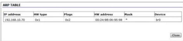
ARP Table
When ARP Table is selected, the below pop up screen comes up listing all ARP entries:
Bridge Table
This table displays a list of devices connected to the node bridge interface as shown below
| Port No | Mac Address | Is Local | Agein Timer |
| 2 | 00:10:83:5b:ee:46 | no | 87.48 |
| 2 | 00:13:21:0d:51:48 | no | 7.23 |
| 2 | 00:18:f8:a9:c3:bf | no | 104.87 |
| 2 | 00:19:d1:d6:b13:32 | no | 63.66 |
| 2 | 00:1a:a0:de:2d:86 | no | 29.82 |
| 2 | 00:1b:78:30:40:e6 | no | 33.78 |
| 2 | 00:1b:78:ba:20:8a | no | 5.62 |
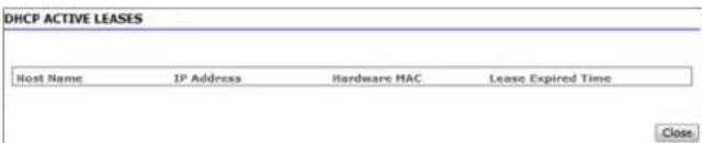
DHCP Active Leases
This table displays a list of active DHCP leases if this node were configured as a DHCP server.
8.7 ADMIN Page - Client or Access Point
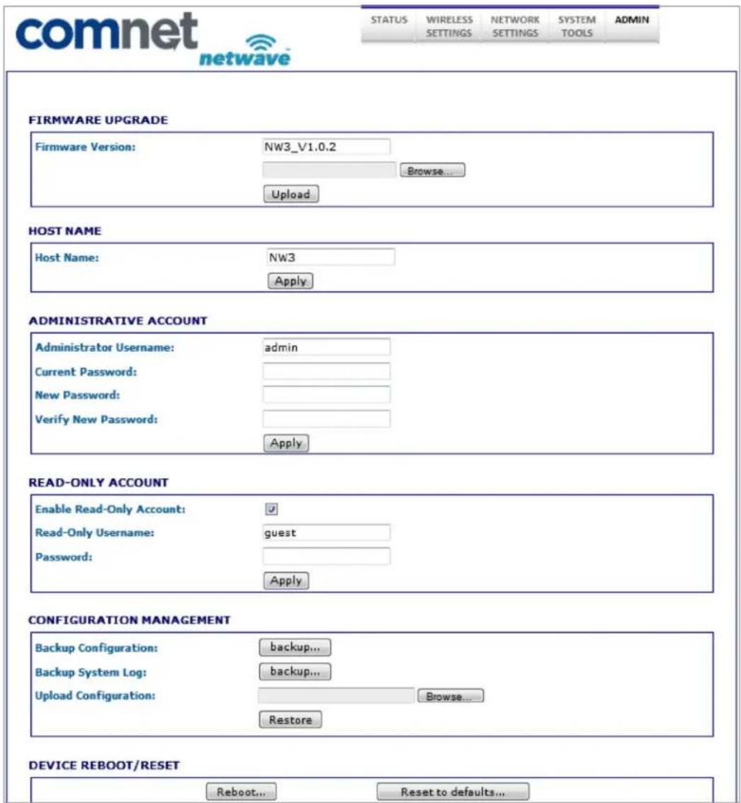
8.7.1 ADMIN Page FIRMWARE UPGRADE Section
Firmware Version: Displays the version currently running
Firmware Upgrade procedure:
- Press the browse button to browse to a location where the upgrade image is located
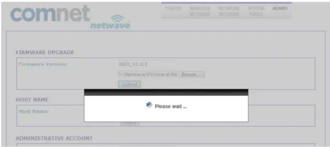
- Once the file has been located hit the Upload button. You should see the following screen while the image is uploading:
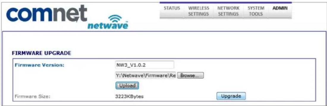
- Once the image has been uploaded, an Upgrade button will appear as shown:
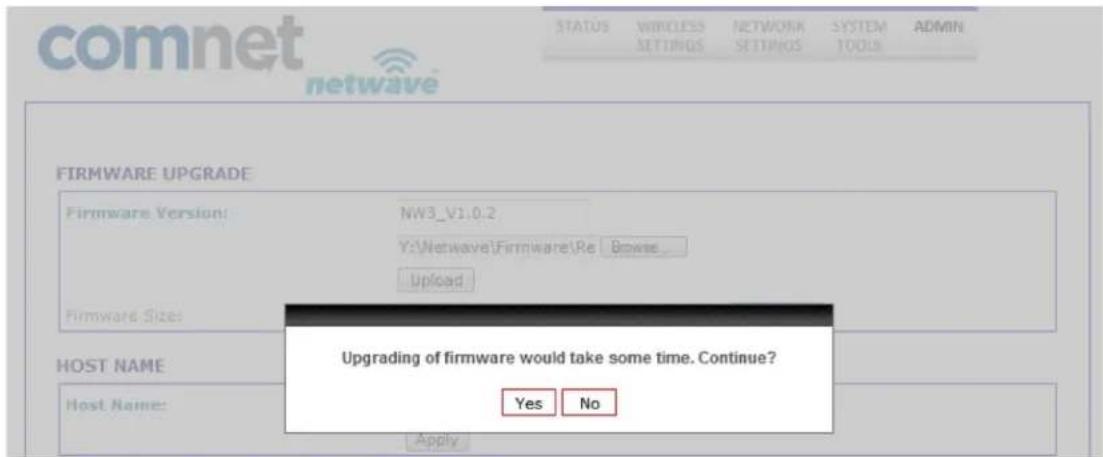
- Press the upgrade button and you should see a prompt confirming the upgrade to continue. Select Yes:
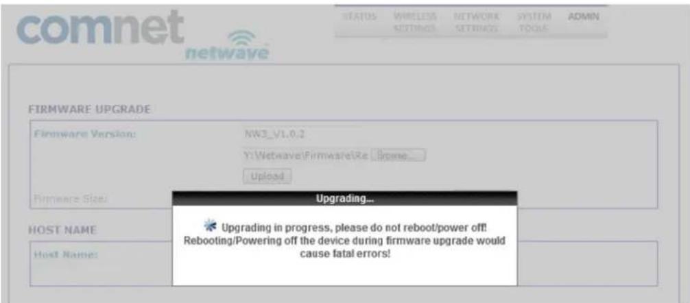
- The following screen will now show reminding the user to not reboot during an upgrade process. This screen should render for at least 60 seconds if the PC browsing to this particular node is locally connected.
Note: If a firmware upgrade is being performed on a node connected on the remote end of a wireless connection, It may take several minutes for this screen to clear as the link needs to re-establish and connections to restart. One may have to clear ARP cash on the connected PC by issuing arp -d command at the command prompt.
• The last screen will confirm to reboot. Hit Yes.

- Unit will reboot and the page will refresh after about 60 seconds.
- It is recommended that a factory reset be performed by hitting the Restore to Default button at the bottom of the ADMIN page but may not be required. Consult ComNet tech support for further detail on the particular upgrade or refer to the firmware release notes.
• End of Firmware upgrade procedure
8.7.2 ADMIN Page HOST NAME Section
Enter in the desired host name.
Remember to select Apply if any changes were made.
8.7.3 ADMIN Page ADMIN ACCOUNT Section
Administrator Username Default is admin
Current Password Default is admin
Remember to select Apply if any changes were made.
8.7.4 ADMIN Page READ-ONLY ACCOUNT Section
The read only account is for monitoring only with no configuration authorization
Enable Read-Only Account Enabled by Default
Read-only Username Default is guest
Password Default is guest
Remember to select Apply if any changes were made.
8.7.5 ADMIN Page CONFIG MANAGEMENT Section
This section allows the user to save the current configuration of the node in a file allowing backup of node configuration.
| Backup Configuration | When the Backup button is presses, a prompt will pop up asking where to store the configuration file. |
| Backup System Log | When Backup is pressed, a page showing the contents of the current log files will be displayed. This then can be saved. One will have to hit the back button to get to the previous ADMIN page. |
| Upload Configuration | Hit browse to the location of a backup configuration file then hit restore. This will restore the unit configuration to the stored configuration. |
8.7.6 ADMIN Page DEVICE REBOOT/RESET Section
Reboot Button Will reboot the node
Reset to defaults Will restore the node to factory defaults erasing all user set parameters.
10.0 Agency Compliance
FCC
Changes or modifications not expressly approved by the party responsible for compliance could void the user's authority to operate the equipment. This device complies with Part 15 of the FCC Rules. Operation is subject to the following two conditions:
- This device may not cause harmful interference, and
- This device must accept any interference received, including interference that may cause undesired operation.
This equipment has been tested and found to comply with the limits for a Class A digital device, pursuant to part 15 of the FCC Rules. These limits are designed to provide reasonable protection against harmful interference when the equipment is operated in a Industrial environment. This equipment generates, uses, and can radiate radio frequency energy and, if not installed and used in accordance with the instruction manual, may cause harmful interference to radio communications. Operations of this equipment in a residential area is likely to cause harmful interference in which case the user will be required to correct the interference at his own expense.
Industry Canada
This Class A digital apparatus complies with Canadian ICES-003. To reduce potential radio interference to other users, the antenna type and its gain should be so chosen that the equivalent isotropically radiated power (EIRP) is not more than that permitted for successful communication. This device complies with Industry Canada license-exempt RSS standard(s).
Operation is subject to the following two conditions:
• This device may not cause interference, and
- This device must accept any interference, including interference that may cause undesired operation of the device.
The antennas used for this transmitter must be installed to provide a separation distance of at least 2.52m from all persons and must not be located or operating in conjunction with any other antenna or transmitter.
CE marking on this product represents the product is in compliance with all directives that are applicable to it.
This equipment may be operated in the following countries:
Great Britain and Northern Ireland, Austria, Belgium, Denmark, Finland, France, Germany, Ireland, Italy, Netherlands, Norway, Portugal, Romania, Switzerland, Sweden
Installer Compliance Responsibility
Devices must be professionally installed and it is the professional installer's responsibility to make sure the device is operated within local country regulatory requirements.
RoHS/WEEE Compliance Statement
European Directive 2002/96/EC requires that the equipment bearing this symbol on the product and/or its packaging must not be disposed of with unsorted municipal waste. The symbol indicates that this product should be disposed of separately from regular household waste streams. It is your responsibility to dispose of this and other electric and electronic equipment via designated collection facilities appointed by the government or local authorities. Correct disposal and recycling will help prevent potential negative consequences to the environment and human health. For more detailed information about the disposal of your old equipment, please contact your local authorities, waste disposal service, or the shop where you purchased the product.
11.0 GPL (General Public License) Statement
You may have received from ComNet products that contained - in part - free software (software licensed in a way that ensures your freedom to run, copy, distribute, study, change and improve the software). Such products include NetWave series of products.
As part of these products, ComNet may have distributed to you hardware and/or software that contained a version of free software programs developed by the Free Software Foundation, a separate not-for-profit organization without any affiliation to ComNet.
See http://www.gnu.org/philosophy/free-sw.html for more details. If ComNet distributed any portions of these free software programs to you, you were granted a license to that software under the terms of either the GNU General Public License or GNU Lesser General Public License "License", copies of which are available from http://www.gnu.org/licenses/licenses.html. The Licenses allow you to freely copy, modify and redistribute that software without any other statement or documentation from us.
ComNet will provide to anyone who contacts us at the contact provided below, for a charge of no more than our cost of physically performing source code distribution, a complete machine-readable copy of the complete corresponding source code for the free software programs used in the version of the programs that we distribute to you. The cost will be free if the delivery medium of the machine-readable copy is through the Internet.
Contact information:
Email: techsupport@comnet.net
Tel: 203-796-5300
Address: 3 Corporate Drive, Danbury, CT 06810 USA
We will reply within 7 working days once the request has been made through email or telephone.
ComNet Customer Service
Customer Care is ComNet Technology's global service center, where our professional staff is ready to answer your questions at any time.
Email ComNet Global Service Center: customercare@comnet.net
Contact Information
ComNet - www.comnet.net
| North America | ComNet Corporate Headquarters and Customer Support Center | Tel: +1-203 -796 -530 0Tel: +1-888-6789427Email: info@comnet.net |
| EMEA, PACRIM, South America | ComNet Europe Ltd, Leeds | Tel: +44 (0)113 307 6400Tel: +44 (0)113 307 6409Email: info-europe@comnet.net |
- Communication Networks
- INSTALLATION AND OPERATION MANUAL
- INDUSTRIAL OUTDOOR 802.11A/N WIRELESS ETHERNET
- This manual serves the following ComNet Model Numbers:
- About This Guide
- Related Documentation
- Website
- Support
- Safety
- Contents
- About This Guide 2
- Overview 4
- Overview
- Legal Information
- Copyright
- Disclaimer
- Introduction
- Point to Multi-Point - NW1 and NW2
- Point to Point Systems - NWK1 and NW2
- Cabling Requirements
- Hardware Installation
- NW1 and NW2 Outdoor Ethernet Gland Installation
- Note: Maximum length of the RJ-45 CAT5 cable is 90 meters.
- Note: DC Passive PoE input for the NW1 and NW2 is 24 VDC.
- NW1 and NW2 Indicating LED Details
- NW1 and NW2 Outdoor Standard Mounting Hardware
- NW1 and NW2 Outdoor Upgrade Mounting Hardware
- Key Default Configurations
- Quick Configuration
- Detailed Configuration
- STATUS Page - Access Point
- STATUS\_AP Page MAIN Section
- STATUS\_AP Page LAN SETTING Section
- STATUS\_AP Page RADIO Section
- STATUS\_AP Page CONNECTED STATIONS Section
- STATUS\_AP Page LOCAL AP ERRORS Section
- STATUS-Client Page - Client
- STATUS-Client Page MAIN Section
- STATUS-Client Page LAN SETTING Section
- STATUS-Client Page RADIO Section
- STATUS-Client Page LOCAL STATION STATICS Section
- STATUS-Client Page LOCAL STATION ERROR Section
- WIRELESS SETTINGS Page - Access Point
- WIRELESS SETTINGS-AP Page BASIC WIRELESS SETTINGS Section
- WIRELESS SETTINGS-AP Page WIRELESS SECURITY Section
- WIRELESS SETTINGS-AP Page LONG RANGE PARAMETERS Section
- WIRELESS SETTINGS-AP Page RSSI LED INDICATOR Section
- WIRELESS SETTINGS-Client Page - Client
- comnet
- BASIC WIRELESS SETTINGS (RADIO 1)
- REMOTE AP - WIRELESS SECURITY:
- LONG RANGE PARAMETERS (RADIO 1)
- RSSI LED SETTINGS (RADIO 1)
- WIRELESS SETTINGS-Client Page BASIC WIRELESS SETTINGS Section
- WIRELESS SETTINGS-Client Page WIRELESS SECURITY Section
- Remember to select Apply Settings if any changes were made.
- WIRELESS SETTINGS-Client Page LONG RANGE PARAMETERS Section
- WIRELESS SETTINGS-Client Page RSSI LED INDICATOR Section
- NETWORK SETTINGS Page - Client or Access Point
- NETWORK SETTINGS Page LOCAL AREA NETWORK Section
- NETWORK SETTINGS Page DHCP SERVER RESERVATIONS Section
- NETWORK SETTINGS Page BANDWIDTH CONTROL Section
- SYSTEM TOOLS Page - Client and Access Point
- SYSTEM TOOLS Page STP Section
- SYSTEM TOOLS Page PING WATCHDOG Section
- SYSTEM TOOLS Page AUTO-REBOOT Section
- SYSTEM TOOLS Page SNMP SETUP Section
- SYSTEM TOOLS Page NTP SETUP Section
- SYSTEM TOOLS Page TELNET SERVER Section
- SYSTEM TOOLS Page SYSTEM SERVER Section
- SYSTEM TOOLS Page Diagnostic Tools Section
- Throughput Test
- Throughput Monitor
- Ping Utility
- ARP Table
- Bridge Table
- DHCP Active Leases
- ADMIN Page - Client or Access Point
- ADMIN Page FIRMWARE UPGRADE Section
- Firmware Upgrade procedure:
- ADMIN Page HOST NAME Section
- ADMIN Page ADMIN ACCOUNT Section
- ADMIN Page READ-ONLY ACCOUNT Section
- ADMIN Page CONFIG MANAGEMENT Section
- ADMIN Page DEVICE REBOOT/RESET Section
- Agency Compliance
- FCC
- Industry Canada
- Installer Compliance Responsibility
- RoHS/WEEE Compliance Statement
- GPL (General Public License) Statement
- ComNet Customer Service
- Contact Information
Brand : ComNet
Model : NetWave NW1
Category : Access Point