Focus Bolt - Hi-Fi System SmallHD - Free user manual and instructions
Find the device manual for free Focus Bolt SmallHD in PDF.


User questions about Focus Bolt SmallHD
0 question about this device. Answer the ones you know or ask your own.
Ask a new question about this device
Download the instructions for your Hi-Fi System in PDF format for free! Find your manual Focus Bolt - SmallHD and take your electronic device back in hand. On this page are published all the documents necessary for the use of your device. Focus Bolt by SmallHD.
USER MANUAL Focus Bolt SmallHD
Regulatory Information.... 5
Legal Information....6
Hardware....7
BT-1 Remote 8
User Interface....12
User interface quick-start (joystick)....13
User interface quick-start (touchscreen)....19
Working with Pages 23
Output Page 24
Touchscreen Gestures 25
Multi-View Page 27
Pixel Zoom....28
Settings Menu 31
Tutorial for Joystick Monitors (section) 32
Input/Output 33
Wireless Pairing 40
Display 46
Controls 52
Capture 60
Accessories 63
Interface....65
User 69
System 72
Camera Control 74
ARRI CAMERA CONTROL 75
RED CAMERA CONTROL....79
Tools - Framing 81
Aspect (guides) 82

SmallHD User Manual
Safe (guides) 87
Crosshair 90
Crosshatch 92
Tools - Exposure....94
Exposure Assist (False Color) 95
Zebra 115
Color Picker 123
Tools - Scopes....130
Histogram....131
Waveform 139
Vectorscope 150
Tools - Focusing....157
Focus Assist....158
Peaking 164
Tools - Overlay....166
Look (3D LUT)....167
Image Overlay....172
Image Capture 178
Audio Meters 190
Metadata 193
Tools - Scale....195
Crop & Scale 196
Size & Position 204
Anamorphic 210
Tools - Addons 212
RT Teradek Motion Overlay 213
Shotover Gimbal Overlay 215
Firmware Updates....216
OS3 Software Update....217
Samples & Tutorials....219
How to use Look (3D LUT) files with your monitor 220
How to auto-calibrate your monitor 221
How to make a LUT....222
How to use Tools - Case Study (Touchscreen) 227
How to use Tools - Case Study (Joystick)....239
Exposure - Case Study 251
Focusing Tips....264
Regulatory Information
Legal Information

On product information can be found in the monitor's Settings menus under Compliance.
FCC 15.21 Information to user
Please be aware that changes or modifications not expressly approved by the party responsible for compliance could void the user's authority to operate the equipment.
FCC 15.105 Class A compliance statement
NOTE: This equipment has been tested and found to comply with the limits for a Class A digital device, pursuant to part 15 of the FCC Rules. These limits are designed to provide reasonable protection against harmful interference when the equipment is operated in a commercial environment. This equipment generates, uses, and can radiate radio frequency energy and, if not installed and used in accordance with the instruction manual, may cause harmful interference to radio communications. Operation of this equipment in a residential area is likely to cause harmful interference in which case the user will be required to correct the interference at his own expense.
Hardware
BT-1 Remote
The SmallHD BT-1 Remote allows wireless control of our on-camera monitors. This can be useful when the monitor is in an inaccessible location, touching the monitor might disturb the camera, or when using a touchscreen is not a good option.
Compliance Information
Model: BTR1
FCC ID: 2AELXBTR1
IC: 20120-BTR1
This device complies with Part 15 of the FCC rules. Operation is subject to the following two conditions: (1) This device may not cause harmful interference, and (2) this device must accept any interference received, including interference that causes undesired operation.
FCC Statement
NOTE: This equipment has been tested and found to comply with the limits for a Class B digital device, pursuant to Part 15 of the FCC Rules. These limits are designed to provide reasonable protection against harmful interference in a residential installation. This equipment generates, uses, and can radiate radio frequency energy and, if not installed and used in accordance with the instructions, may cause harmful interference to radio communications. However, there is no guarantee that interference will not occur in a particular installation. If this equipment does cause harmful interference to radio or television reception, which can be determined by turning the equipment off and on, the user is encouraged to try to correct the interference by one or more of the following measures:
- Reorient or relocate the receiving antenna.
-
Increase the separation between the equipment and receiver.
-
Connect the equipment into an outlet on a circuit different from that to which the receiver is connected.
- Consult the dealer or an experienced radio/TV technician for help.
47 CFR Part 15.21 FCC Statement

CAUTION: changes or modifications not expressly approved by the party responsible for compliance could void the user's authority to operate the equipment.
FCC Exposure Statement
This equipment complies with FCC radiation exposure limits set forth for an uncontrolled environment. This equipment is in direct contact with the body of the user under normal operating conditions. This transmitter must not be co-located or operating in conjunction with any other antenna or transmitter.
The BT-1 Remote will work with any of our monitors that are not Legacy Products:
- 500 Series
- 700 Series
- FOCUS Series
- Cine7 Series
The remote can only be paired with one monitor at a time, but you can pair multiple remotes with one monitor (up to 3).
Connecting the Remote
To connect the remote, go to the Settings menu under Remote and make sure it is enabled. Hold the blue joystick down for about 5 seconds. You should see the Remote link under the status column. Select it on the monitor and it will "bind". Once this is tied (Active), it will work as a normal joystick would. It will blink blue light slowly when paired. It will blink fast blue when not paired. If pairing fails, try power cycling the monitor.
When first connecting your remote to a monitor, or after any firmware update on the monitor, your remote's firmware may be automatically updated by the monitor. This update may take up to 4 minutes. Please keep the remote next to the monitor during this time. If the update is interrupted, such as from the remote moving out of range of the monitor, erratic behavior including persistent disconnects may occur. If you experience this behavior, turn the remote off and back on and allow the monitor to update the remote's firmware.
Settings
Selecting an "active" remote in the menu setting will give a few options for joystick orientation:
• 90°
- Filp X
- Filp Y
There is also a setting to Unbind the remote. You will need to "unpair" a remote to have it work on another monitor. This is done through the Menu Settings. Have both the remote on and the monitor on. Select "active" and choose "unbind".
Battery
If the remote is blinking red and blue quickly, you will need to replace the batteries. It takes 2× CR1620 watch style batteries.
Controls
The remote has four buttons:
The Joystick, which can be clicked to select and moves up, down, left, and right. This will act the same as the joystick on the monitor or your touch interactions on a touch screen.
The Back or Close button [<]. This allows you to cancel an action or return to a previous screen.
There is an Image Capture button [0]. This allows you to use the image capture function and will work even without the tool being active. It works just like the hardware image capture button on SmallHD 501, 502, 701, and 702 monitors.
The power Button (located on top of the remote above the Joystick). You can power off the monitor using the remote and also power it back on.

The power button will not turn the monitor on if there has been a hard power cycle (where the battery or power source to the monitor has been completely removed or interrupted).
TROUBLESHOOTING TIPS
The Remote won't pair with the monitor.
-Check the batteries, they may need to be replaced.
-You will need to "unpair" a remote to have it work on another monitor. This is done through the Menu Settings. Have both the remote on and the Monitor on. Select "active" and choose "unbind".
-If for some reason the remote is acting incorrectly, you can do a reset by holding the image capture button down until the Red light goes off.
User Interface
User interface quick-start (joystick)
Once you get your monitor plugged in via HDMI or SDI, this is a quick overview of the touchscreen interface. There are more detailed sections in the guide that expands on many of these features, this is a quick overview to get you rolling.

A tutorial is built into the monitor itself under Settings > Help which will run you through the basics via on-screen prompts. This written guide can be followed separately if you don't have a monitor in your hands to train with.
Navigation & Interface
To Navigate, simple use of the joystick nob to move :
Left or Right - to change Pages
Down - Enter Pages mode
UP - Zoom or Exit Pages mode
Click (press in, toward the back of the panel) - select and open TOOL bar
Back button (<) - click to close or navigate back/ exit. (on some models, the Back Button is also the power button, used by Holding for 3+ seconds).
Function (F#) buttons can be programmed as shortcuts.
Pixel Zoom
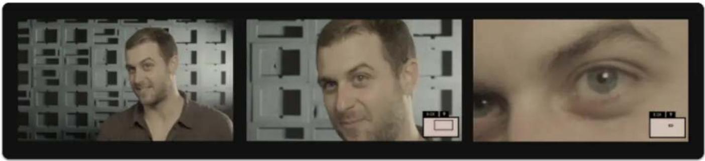
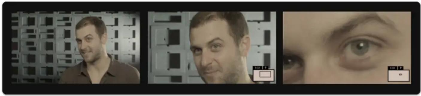
To zoom into any page for quick spot checks, press up on the joystick.
natural_image
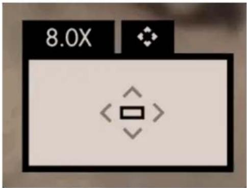
Three-panel image showing a man in a lab setting, a close-up of his face, and a close-up of an eye (no visible text or symbols)To pan when zoomed in, click the joystick.
text_image
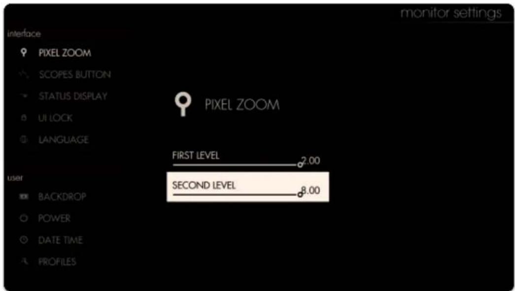
8.0XIf you wish to adjust the maximum zoom level go to Settings > Interface > Pixel Zoom
text_image
interface PIXEL ZOOM SCOPES BUTTON STATUS DISPLAY UI LOCK LANGUAGE PIXEL ZOOM FIRST LEVEL 2.00 user SECOND LEVEL 8.00 BACKDROP POWER DATE TIME PROFILES monitor settingsSelect an Input
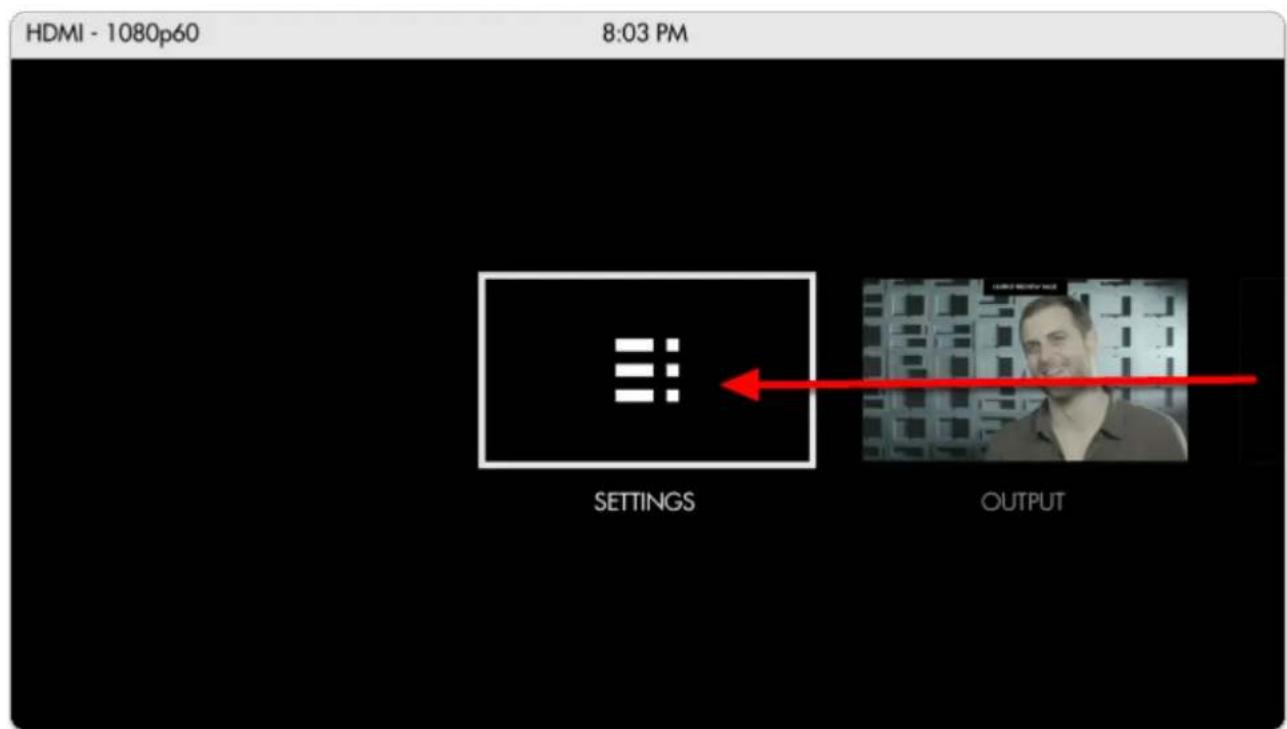
To start, ensure you have an input being displayed on your monitor by visiting the Settings page.
text_image
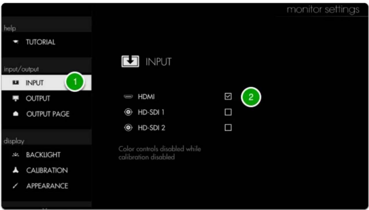
HDMI - 1080p60 8:03 PM SETTINGS OUTPUTTo select the monitor's input press the joystick left until you reach the Monitor Settings page. Navigate with the joystick to the (1) Input section and click to go 'into' the input menu. From here (2) select HDMI or HD-SDI depending on which signal you wish to display.
text_image
monitor settings help TUTORIAL input/output INPUT OUTPUT OUTPUT PAGE display BACKLIGHT CALIBRATION APPEARANCE INPUT HDMI HD-SDI 1 HD-SDI 2 2 Color controls disabled while calibration disabledPress the Back button once to access the rest of the settings menu, and press it once more to get to a zoomed-out view of all the monitor's 'Pages'
PAGES

The SETTINGS, page contains all the monitors attributes, Preferences which controls settings that affect the entire monitor is always located to the far left.
The OUTPUT page allows for you to see/select what signal you are sending downstream (on applicable models).
The CONTROL page allows for camera control (on applicable monitors, with appropriate license- sold separately).
The MULTI-VIEW page allows for Side-by-side viewing of two inputs (on applicable models).
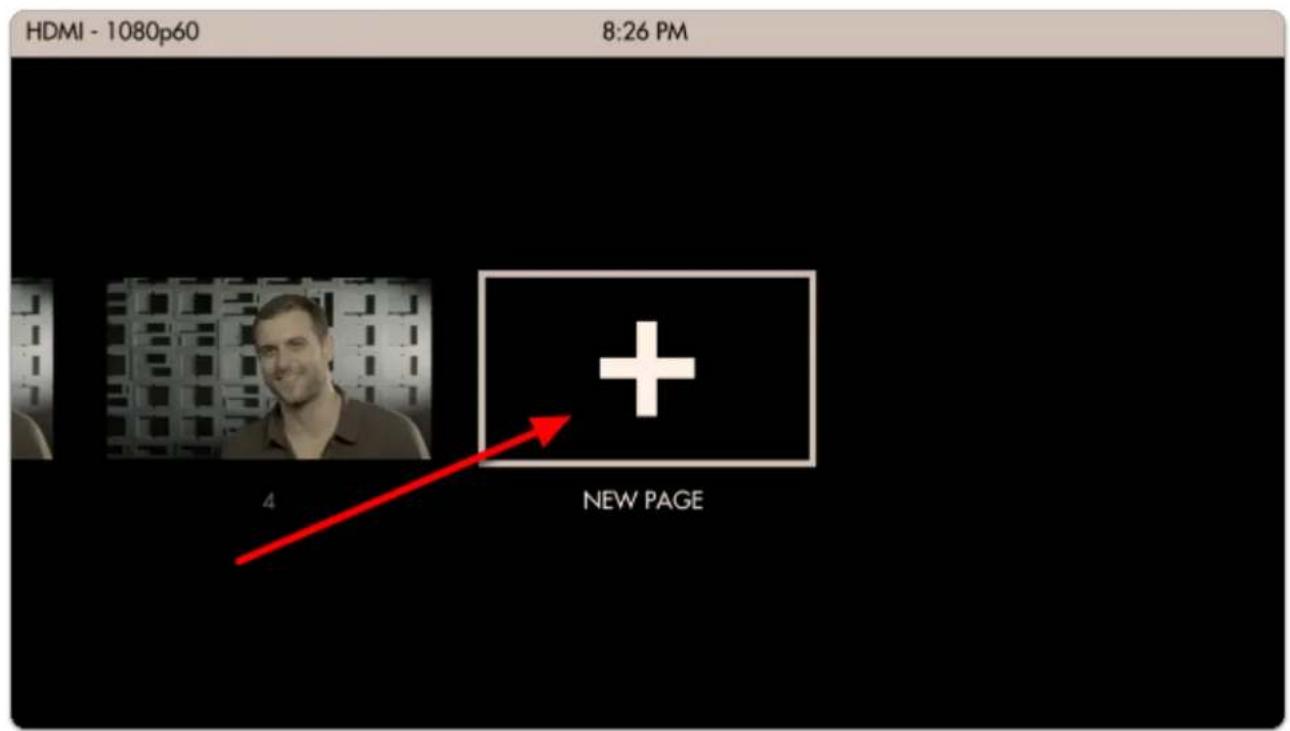
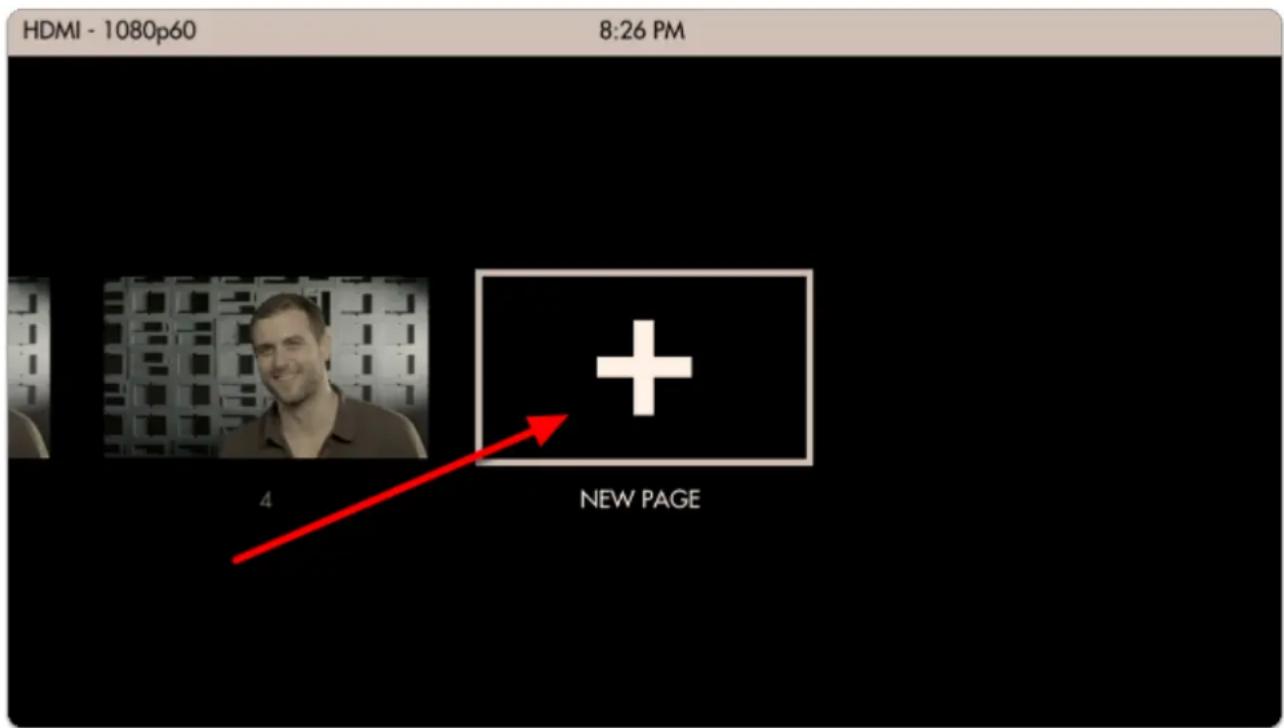
While still zoomed-out, scroll all the way to the right and click the joystick (or press upward) when the '+' is selected. This will add a brand new page that you can customize however you wish to accomplish a range of on-set tasks. You can create a maximum of 8 pages.
text_image
HDMI - 1080p60 8:26 PM 4 NEW PAGE
The entire monitor is based on the concept of customizablePages- instead of having to enable and disable features individually when needing to change a setup, create pages with a task in mind, for example setting exposure, and quickly joystick (switch) between each page on-set for a highly efficient workflow.
Using TOOLS
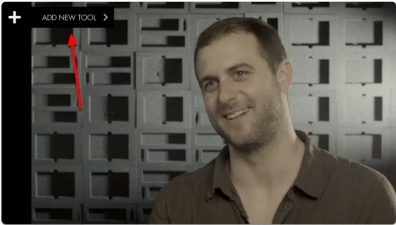
Click the joystick to bring up the 'add new tool' menu.
Tools can apply to a single page or all pages.
You can have up to 8 tools in use on a page at the same time (this includes the Global tools).
To Delete a tool, select it, and touch the trashcan icon on the bottom. It will ask you to confirm you want to delete it and selecting it again will remove the tool form your toolbar.
text_image
ADD NEW TOOL >
Tools offer a variety of... well... tools, to help you in your filmmaking process and workflows. This should not be associated with the PA who is just there because his Uncle is a producer... These are helpful tools. :)
TOOLS are broken down into subsections:
FRAME
EXPOSE
SCOPES
FOCUS
OVERLAY
SCALE
ADDONS
User interface quick-start (touchscreen)
Once you get your monitor plugged in via HDMI or SDI, this is a quick overview of the touchscreen interface. There are more detailed sections in the guide that expands on many of these features, this is a quick overview to get you rolling.
GESTURES - Introduction
There are many touchscreen gestures that are outlined here. Below are some basics to get you up and running.
To Navigate, simple use one finger to move (swipe):
Left or Right - to change Pages
Down - Enter Pages mode
UP - Exit Pages mode
Tap to Select and open the TOOL bar on a page.
Pinch-to-zoom (fingers stat apart and pinch together) activates the 'Pixel Zoom' function, giving you a clear view of your signal for critical focusing & catching tiny details. The PIXEL ZOOM function that allows for a digital zoom on your image. This is helpful for a detailed view of your image for critical focusing & catching tiny details.
natural_image
Three-panel image showing a man in a grid-patterned room, a close-up of his face with a green eye, and a close-up of the eye's eyes (no text or symbols visible)PAGES
The entire monitor is based on the concept of customizable Pages - instead of having to enable and disable features individually when needing to change a setup, create pages with a task in mind, for example setting exposure, and quickly swipe between each page on-set for a highly efficient workflow.
For a zoomed-out overview of your pages, swipe down on the monitor. Create a new page by swiping over to the far right and tapping on '+ New Page'. More info on Pages can be found here
text_image
HDMI - 1080p60 8:26 PM 4 NEW PAGE
The SETTINGS, page contains all the monitors attributes, Preferences which controls settings that affect the entire monitor is always located to the far left.
The OUTPUT page allows for you to see/select what signal you are sending downstream (on applicable models).
The CONTROL page allows for camera control (on applicable monitors, with appropriate license- sold separately).
The MULTI-VIEW page allows for Side-by-side viewing of two inputs (on applicable models).
Using TOOLS
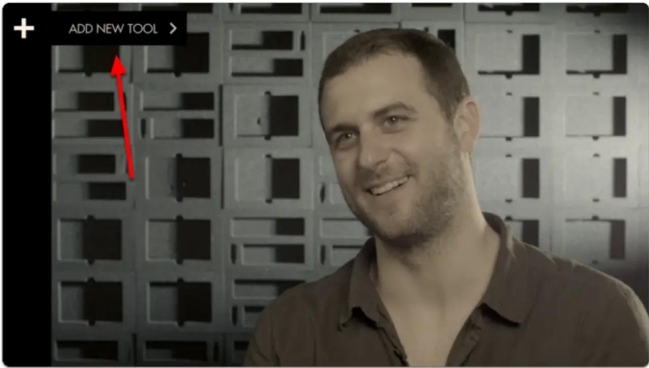
Tap the screen to bring up the 'add new tool' menu.
Tools can apply to a single page or all pages.
You can have up to 8 tools in use on a page at the same time (this includes the Global tools).
To Delete a tool, select it, and touch the trashcan icon on the bottom. It will ask you to confirm you want to delete it and selecting it again will remove the tool form your toolbar.
text_image
ADD NEW TOOL >Tools offer a variety of... well... tools, to help you in your filmmaking process and workflows. This should not be associated with the PA who is just there because his Uncle is a producer... These are helpful tools. :)
These TOOLS are broken down into subsections:
FRAME
EXPOSE
SCOPES
FOCUS
OVERLAY
SCALE
ADDONS
Working with Pages
Pages allows you to have several different views set up using tools on multiple screens that can be customized to the users needs. This will allow you to quickly swipe/ joystick between screens with applied tools. i.e. This can be helpful when needing to use False color or Scopes to check exposure and then want to return to see the final LUT look applied while shooting with your audio tool.
{VID}?
Pages can be Added, Moved (in order, Left or Right), Deleted or Named. To enter Pages Mode, swipe/joystick down.
{pic}
From here, to add a new Page, click the PLUS sign. You can create a maximum of 8 Custom Pages in SmallHD OS3, not including the Settings Page, Output Page, Control Page or Multi-View Page (if available on your monitor).
{pic}
You can also RENAME, MOVE, or DELETE a page by selecting the box with downward carrot or arrow.
{PIC}
Troubleshooting TIPS
In Pages view, you can see what signal the monitor thinks it is receiving from the selected input in the upper left corner. You can also see the time and power data, even if you have the status bar hidden when working on a page.
Tools can be applied to all pages or by page individually. (OS 3.4+)
Output Page
This page will show you what you are outputting. This page can be turned off in the settings menu.
[pic]
You will have only limited tools on the output page: Look and add ons.
[pic]
Troubleshooting Tips
Output page allows you to see what you are sending downstream to the selected output in the menu settings. Some monitors have a FIXED passthrough on the #2 output from the #2 input.
Touchscreen Gestures
There are several gestures that allow you to control your monitor if it has a touch screen.
Pinch In: Zoom In
This is the same as most mobile devices.
Fingers together then spread apart zooms in.
Fingers apart then together zooms out.
(When Using Pixel Zoom) Two-Finger Drag: Adjust What You Are Seeing
When using the Pixel Zoom tool you can also drag the image around in addition to zooming in and out. When zoomed in, leave two fingers on the screen and move them around in the direction you wish to move the viewing area.
Pinch Out: Zoom Out
This is the opposite of most cell phones. By placing two fingers together and then separating them, the image will zoom out. This will only work if there is signal.
Swipe Left or Right: Page Change
This is done with a single finger anywhere on the screen left or right (horizontally). You will need to move at least an inch in the direction you want to switch pages. When in Pages View you can still swipe between pages.
Swipe Down: Pages View
This is done with a single finger anywhere on the page swiping down about a half inch or so. In pages mode you can see all your pages; they appear in a smaller view. You will also get metadata at the top of
the screen, like the video signal you are receiving and the time and battery life. This will be present even if you have the Status bar hidden, so it is a way to check that data if you do not want to see it on a page.
Hold (3 Seconds): UI Lock/Unlock
There is a UI lock that is activated in the Menus>Interface>UI Lock. This must be checked to function. Once checked, hold a single finger on the screen for 3 seconds. You will see a status bar near the top center as it locks. Once locked, it will say "Locked". To unlock, you will need to repeat the 3 second hold with a single finger. There will be no progress bar, but after 3 seconds you will see a message at the top of the screen "Unlocked".
Two-Finger Swipe: Jump to Settings Menu from a Page or from Settings Menu back to the Last Page
Using two-finger swiping from the Left to Right you will jump directly to the Settings menu page. Using a two-finger swiping motion while in the Settings menu from Right to Left will take you back to the page you were on. This gesture is helpful if you are several pages in and want to access the Settings menu quickly. Another way would be to go to pages view and select the Settings page. Using the two-finger swipe off the menus will take you back to the last page you were on.
Tap: Open Toolbar
A single tap on a page screen will bring up the toolbar on the left. The toolbar will disappear on its own if there is no interaction after 5 seconds. Here you can add your tools, enable or disable tools, or adjust their settings. For more information please see the tools section of the guide.
(While the Toolbar is Open) Swipe Right: Opens Selected Tool's Configuration Menu
Select a tool by touching it on the toolbar. A tool will remain selected even after the toolbar hides itself. Swiping with a single finger left to right will open the menu for that selected tool. After you finish adjusting the settings you can return to the page by either taping the screen or swiping right to left.
Multi-View Page
Multi-view will allow you to view two inputs side by side.
On the Left side will be your primary input (this is the input on all of your pages).
On the Right side, this will be your secondary input, which is only viewable on the Multi-View page.
{PIC}
Multi-View in OS3
You can toggle your inputs by selecting the screen and then changing your INPUT. You can do with with an assigned button or navigating through the menus.
*Inputs will vary depending on Monitor Model (HDMI, SDI, WIRELESS)
{PIC}
Troubleshooting Tips
Multi-View screen size and placement are fixed.
Changing your primary input (what you see on your pages) will change the input on the left side of the Multi-View page.
Pixel Zoom
natural_image
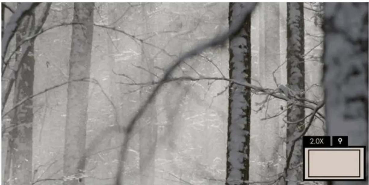
Black-and-white photo of frost-covered trees with bare branches, no visible text or symbolsZooms directly into your image on the monitor to get you an exact idea of your focus distance and any other fine details.
This tool requires a video feed.
Pixel Zoom - Overview
Enable Pixel Zoom by pressing up on the joystick or pinch-to-zoom/swipe up on touchscreen monitors when viewing your camera feed normally. When zoomed in, press the joystick/tap to switch to pan mode to move around the image.
With Pixel Zoom it's very easy and thorough to set proper focus when you have time to do so but the other methods- Focus Assist and Peaking can often be used more quickly when added to a page to swipe to for a quick spot-check.
Pixel Zoom gives you a zoomed-in view of your camera's feed which means it's most likely the tool that will enable you to spot areas where you can make improvements, be it precise focus or a piece of set dressing that's not angled correctly towards the camera, a stray light stand in the corner of the shot, etc.
As long as you have no image-altering features activated, Pixel Zoom lets you see exactly your image zoomed in, making it the best tool for 'seeing it for yourself'.
Pixel Zoom - Settings
Because Pixel Zoom isn't added to a page in the traditional way tools operate, its settings can be found in the Settings Menu > Interface > Pixel Zoom
Pixel Zoom - Quick Start
In this section we'll use Pixel Zoom to set focus and enable us to spot issues with our image.
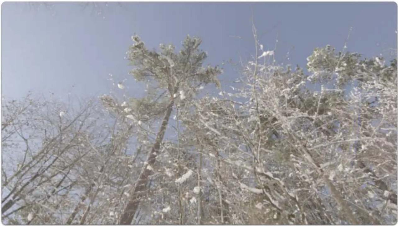
From a distance this outdoor shot looks in focus but using Pixel Zoom reveals we need to make a slight adjustment.
natural_image
Snow-covered evergreen trees against a clear blue sky (no text or symbols visible)If using a touchscreen, pinch-to-zoom to your desired level to check focus. (same and most mobile devices)
If using a joystick, press up to zoom in up to 8x (maximum zoom level may be adjusted in Pixel Zoom Settings).
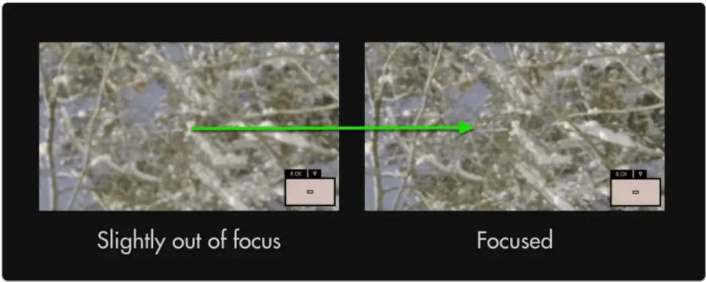
text_image
Slightly out of focus FocusedThough a minor adjustment, this has increased the effective resolution of the entire image.
With 4k and 8k cameras becoming commonplace, achieving proper focus becomes even more important to properly utilize available resolution.

To pan around the image once zoomed-in, click the joystick once and then move in any direction. To pan on touchscreen monitors, drag with one finger around the image when zoomed in.
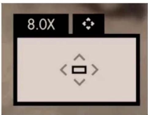
text_image
8.0XPixel Zoom, Focus Assist and Peaking are excellent tools to help keep your shots in focus. We recommend trying each to find which works best for your shooting style.
Settings Menu
Tutorial for Joystick Monitors (section)
Tutorial Settings

TUTORIAL
If you wish to have your monitor teach you about your monitor, this is where to go.
Start Tutorial (button)
START TUTORIAL
Begins a step-by-step overview to get you familiar with the monitor's user interface.
Once the Tutorial is started, you may exit anytime by pressing the BACK (<) button twice quickly at any time.
The Tutorial will walk you though adding a page, adding a tool and swiping between pages.
Input/Output
Define which signal you wish to view and where to output; set up color properties to monitor your footage in its intended color space, for example DCI-P3 for previewing your footage the way it may appear in cinema projection.

Actual Input/Output settings dependent on monitor model.
Input Settings

INPUT
Use this section to choose your input and adjust related settings.
HDMI

HDMI

View the signal plugged into 'HDMI IN'.
SDI 1

HD-SDI 1

View the HD-SDI signal plugged into 'SDI IN 1' (or 'SDI IN' depending on monitor model).
SDI 2

HD-SDI 2

View the HD-SDI source plugged into 'SDI IN 2'.

Dual HD-SDI inputs available on SmallHD's Production monitors (13" and up). SDI 2 is a pass though, only SDI 1 OUT is assignable.

The following options become available when the monitor has been calibrated (see Calibration section for details). This allows you to safely define a color space, white point and Log correction that are within the bounds of your calibration.
Wireless Settings

WIRELESS
Manage settings related to wireless protocols (*Option only available on Teradek TX or RX Integrated monitors).
Airplane Mode
AIRPLANE MODE

If shooting video on an airplane, check this box to disable Wireless if required. This can help save power/ extend your battery life.
Color Space
COLOR SPACE
Here is where you want to select the exact color space your camera is outputting to display properly on the monitor.
White Point
WHITE POINT
Here is where you want to select the white point your camera is outputting to see it reflected on the monitor.
Log Correction
LOG CORRECTION
If your camera is outputting a log-based gamma, here is where you select your intended output color space/gamma.
Output Settings

OUTPUT
Choose how signals flow once you plug in your camera.
HDMI

HDMI

This option will send HDMI 'downstream' via the 'HDMI OUT' port on the monitor.

Any tools you have applied to the Output Page (such as a Look/3D LUT) will display on any monitor connected via HDMI OUT
HD-SDI

HD-SDI

This option will send HD-SDI 'downstream' via the 'HDMI OUT' port on the monitor.

Any tools you have applied to the Output Page (such as a Look/3D LUT) will display on any monitor connected via HD-SDI OUT
Output Page Settings

OUTPUT PAGE
The Output Page enables lets you apply tools to a downstream output just like with any other page, enabling any monitor or TV to display, for example, a properly graded image on set, especially useful for client monitoring.
Always Show
ALWAYS SHOW

If you wish to apply tools to the output of your monitor before an output is physically connected (for example to set it up before shooting), check this option.
Show if Output Enabled
SHOW IF OUTPUT ENABLED

This will enable the output page only if you are outputting a signal. This option is useful when you wish to keep your interface free of clutter when no signal is being output but still allows you the ability to configure it when it is.
Never Show
NEVER SHOW

If you know you will not need to add and configure tools to apply to an output feed, check this option to keep the output page hidden even when an output signal is being sent downstream.
Wireless Pairing
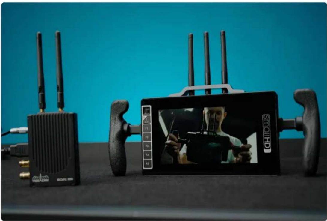
Pair a SmallHD TX Monitor or Teradek TX Transmitter to a SmallHD RX Monitor or Teradek RX Receiver following the steps below.
natural_image
Exterior view of a modern office building (no signage)Enabling Pairing mode on the SmallHD Monitor(s)
Power on your SmallHD and navigate left to access the Settings Menu.
Scroll down & click on INPUT options underneath INPUT/OUTPUT & ensure the input is set to WIRELESS.
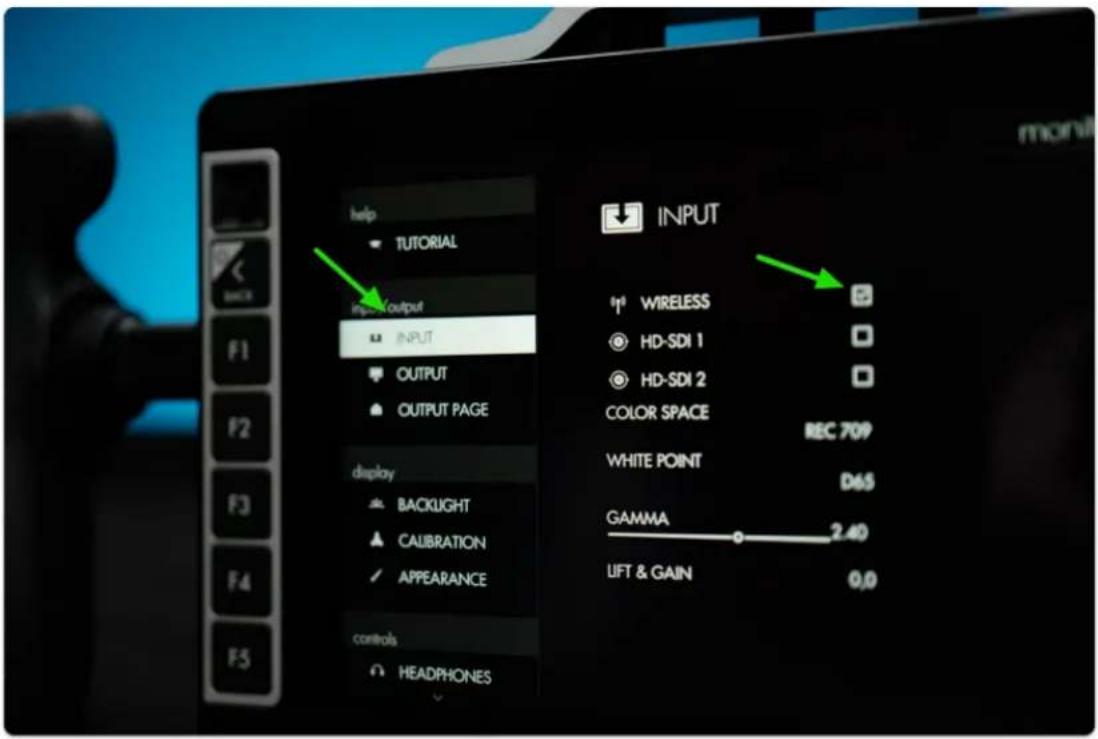
text_image
help TUTORIAL input/output INPUT OUTPUT OUTPUT PAGE display BACKLIGHT CALIBRATION APPEARANCE controls HEADPHONES INPUT 1# WIRELESS HD-SDI 1 HD-SDI 2 COLOR SPACE REC 709 WHITE POINT D65 GAMMA 2.40 LIFT & GAIN 0.0Navigate downward to find the WIRELESS option under the ACCESSORIES category.
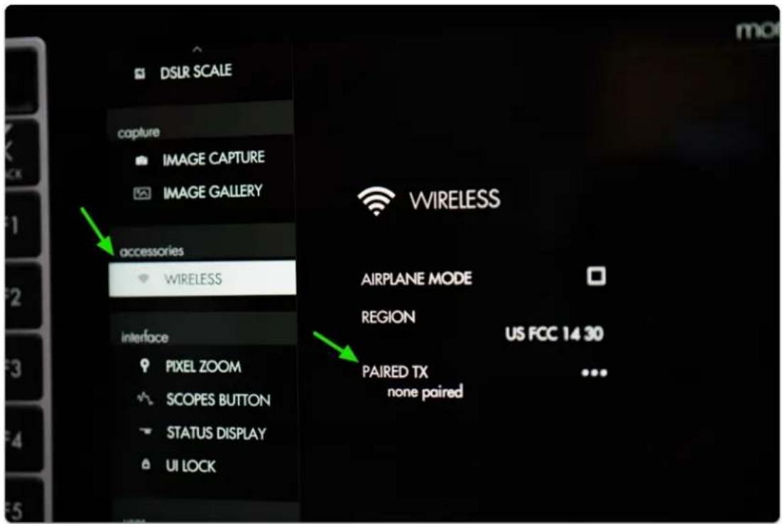
text_image
DSLR SCALE capture IMAGE CAPTURE IMAGE GALLERY accessories WIRELESS interface PIXEL ZOOM SCOPES BUTTON STATUS DISPLAY UI LOCK WIRELESS AIRPLANE MODE REGION US FCC 14 30 PAIRED TX none paired ...
SmallHD User Manual
Click the joystick and select PAIRED TX/RX to enter pairing mode which will wait for a wireless signal from a compatible transmitter(TX) or Receiver (RX). Do this on both the TX and RX if you are pairing two SmallHD monitors.

If a transmitter is already paired and you wish to unpair it, select where it says 'PAIRED TX/RX' and then click the option to 'UNPAIR'.
Pairing to a Teradek Device
First ensure your Teradek device is connected to DC power & a video source/destination via HDMI or SDI.
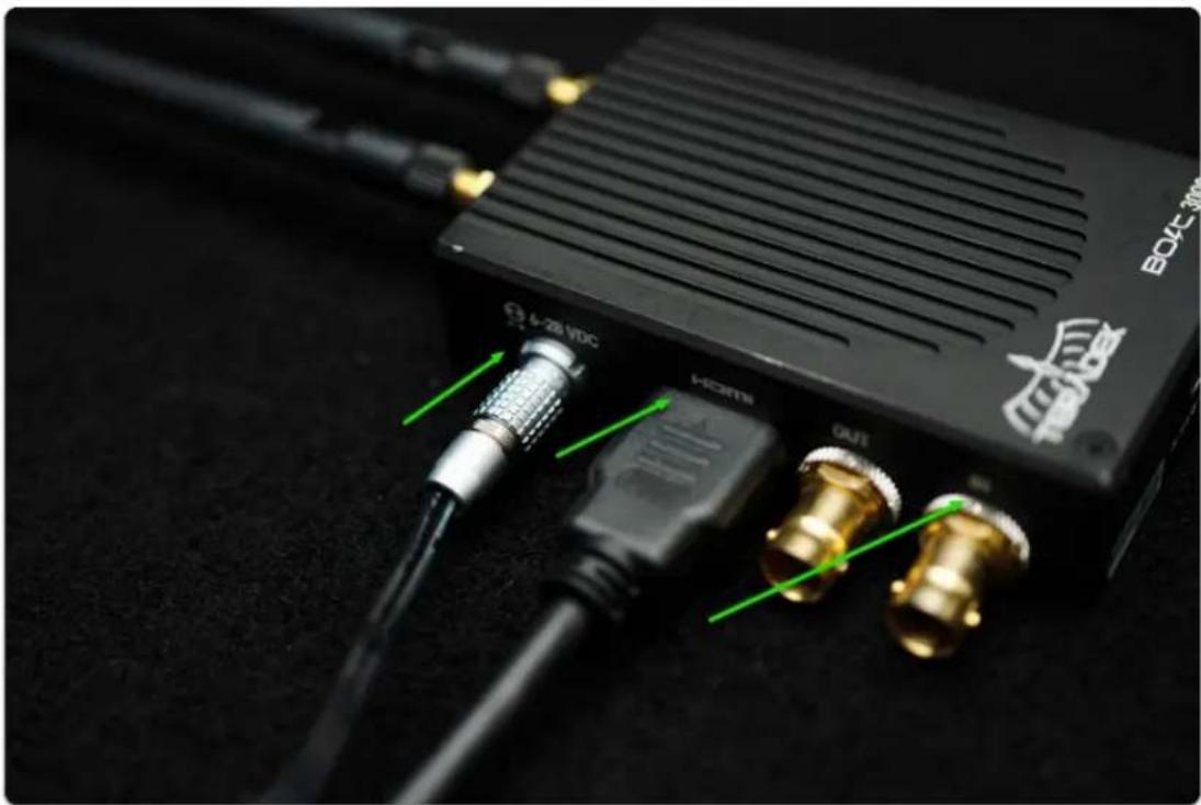
text_image
BOX 300 4-26 VDC HDMI OUTPower on the Teradek via the switch opposite the inputs:

natural_image
Close-up of a black electronic device with indicator lights and a green arrow pointing to a small component (no readable text or symbols)Using a paperclip (or similar precision instrument) press the Reset button on the transmitter until the blue cloud LED begins to blink quickly:
*We recommend using BoltManager software on a computer for the pairing process. You will need a Micro USB cable. and simply hit the pair button.
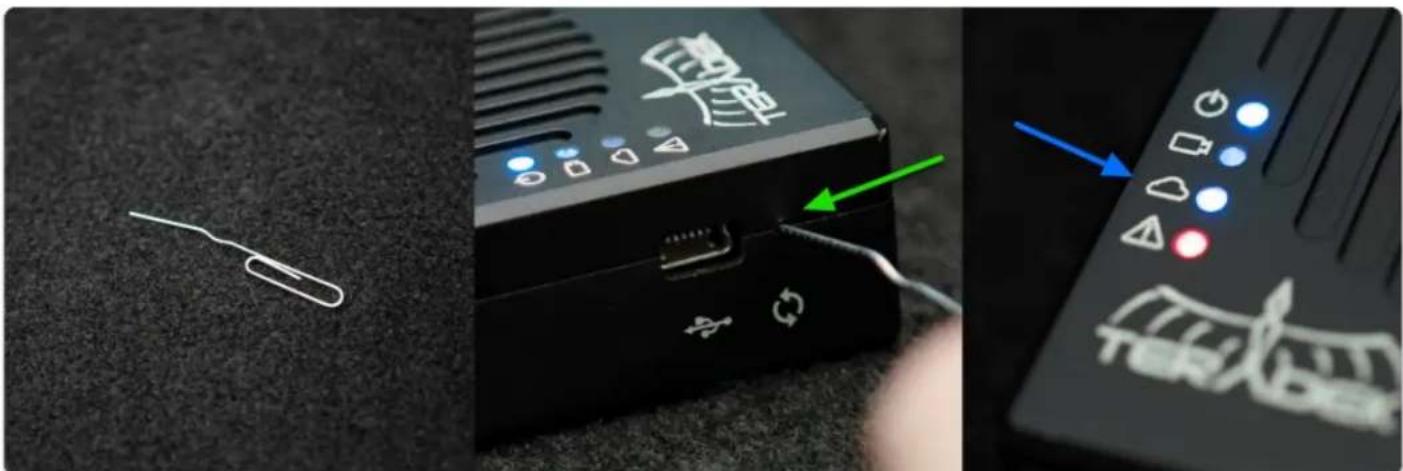
text_image
Close-up of a black remote control device with white annotations and a green arrow pointing to a cable, alongside a close-up of its internal components.Select 'PAIR' on the monitor will begin pairing which typically takes 10-30 seconds but can take up to 3 minutes in the presence of heavy 5Ghz interference.

Wireless interference is a common culprit for pairing issues. If the red fault LED stops blinking without having paired, or the 703 Bolt indicates that pairing has failed - try and move to an area with less wireless traffic specifically in the 5Ghz spectrum (ie away from wifi routers, antenna masts, etc). Once paired, the signal will be far less susceptible to issues caused by interference.
We also advise placing the devices around 1 Meter/ 3 feet apart from one other.
*Sometimes, removing the antennas before starting the pairing process and adding a single after the pairing process has started can help the units work through interference.
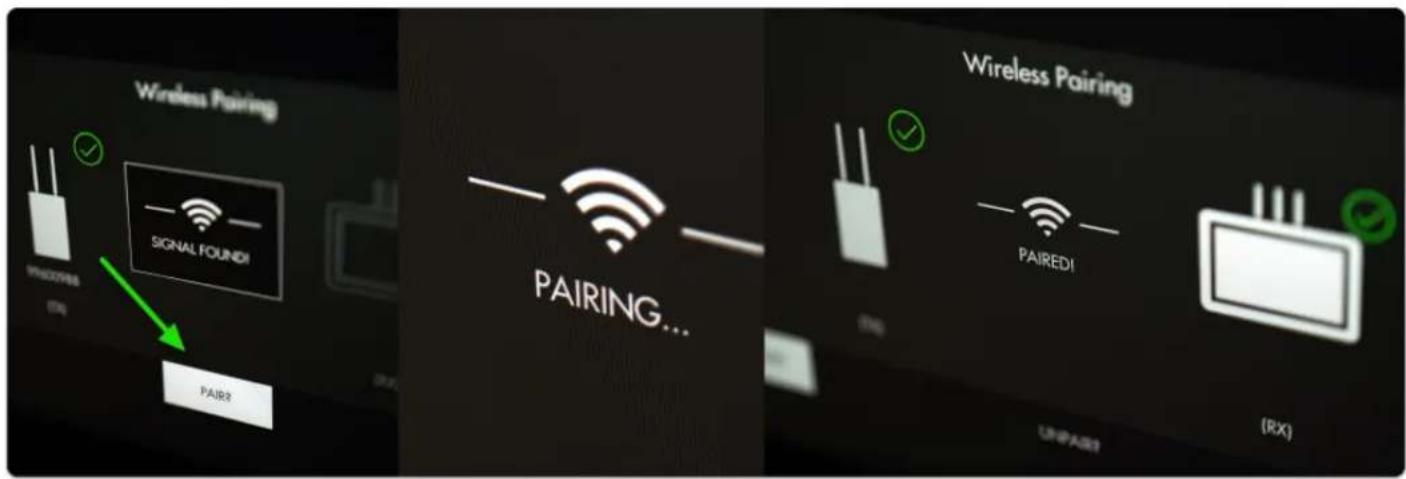
text_image
Wireless Pairing SIGNAL FOUNDI PHOSOPES (EN) PAIRR PAIRING... Wireless Pairing PAIREDI (RX) UNIPARTCongratulations, you're paired up and receiving a wireless signal!
You can confirm by navigating (joystick or swipe) down and in the upper left corner you will see the signal type being sent or received with a green wireless icon.
Teradek Wireless Products compatible with SmallHD Wireless Monitors

The SmallHD Sidekick (SK) RX and 703 Bolt are compatible with: Teradek Bolt 500 (+ LT & XT)
Teradek Bolt 1000 (+ LT & XT)
Teradek Bolt 3000 (+ XT)
Teradek ACE 500
The SmallHD 500 RX/TX series are compatible with:
Teradek Bolt 500 (+ LT & XT)
Teradek ACE 500
TROUBLESHOOTING TIPS FOR WIRELESS PAIRING
*You can only pair one RX to a TX at a time, you can have 4 RX units paired to a single TX.
*We recommend turning off all other wireless TX/RX units and work one at a time on set to help speed up the pairing process.
*Use Bolt-manager (on a computer) if on a Teradek product, it's easier to Pair and be sure everything is up to date. https://teradek.com/pages/downloads#bolt
*Be sure both RX and TX units are up to date on the latest firmware. (You can update the Teradek unit via Bolt-manager).
*The region settings must match between all devices (USA, Europe, Japan Indoor, etc.).
To prevent interference when pairing a transmitter and receiver:
*Turn off all other transmitter/receiver sets, and only turn on the transmitter and single receiver you are trying to pair.
*Turn off any receivers that are already paired to the same transmitter. Only have the transmitter and the one receiver you're trying to pair turned on!
*Have the transmitter and receiver at least 3 feet or 1 meter apart -- do not place them right next to each other!
*Remove the Antennas before pairing. Once you start the pairing process, add a single antenna to both the RX and TX.
*NOTE: Sometimes if there is a lot of interference in the area, it may take a few tries to get the units to lock, continue to try the pairing process.
Display
Settings that affect the output of the display can be found here such as backlight adjustment & auto calibration.

Individual options dependent on monitor model.
Backlight Settings
BACKLIGHT
Set up and fine-tune the brightness of the LED backlight.
STANDARD RANGE
STANDARD RANGE

This option enables adjustment of the backlight up to its maximum limit within the specified color space.
STUDIO BRIGHTNESS
STUDIO BRIGHTNESS

If you are in a studio or other low-light environment, use this option to limit the backlight to 100 nits which enables a fine-tune adjustment within that range.
*Some monitors will default to Studio Brightness if the power source (voltage) is low to help save energy. Change power sources to allow for Full Backlight capabilities.
BACKLIGHT
BACKLIGHT
80
Adjusts the actual output of the backlight or in the case of OLED adjusts the maximum pixel brightness.
* OLED panels do not DIM the same as an LCD, be aware adjusting the brightness of an OLED will affect its performance.
Calibration Settings
CALIBRATION
Your monitor ships calibrated from the factory with selectable calibration colorspace LUTs depending on how you may want to display your image, for example DCI color space for cinema projection or Rec. 2020 for HDR production (available on select monitors).
Auto-calibration can be performed here to account for long-term color drift by using a compatible calibration puck on select monitors. This will automatically set the gamma and white point to ensure your monitor is perfectly displaying its intended color space.
More information about Panel Calibration is located here.
Enable Calibration LUT
ENABLE CALIBRATION LUT

This turns on or off the current Calibration LUT.
*You will want to disable the Calibration LUT when making a new one/ calibrating the monitor.
Calibration LUT
CALIBRATION LUT
If you already have a saved calibration LUT you wish to use, you can browse your SD card and apply it here. Once a LUT is loaded onto the monitor it will save it to the hardware.
*Doing a factory reset on the calibration will reapply the factory LUT that came with the monitor.
Targeted Color Space:
Targeted Color Space:
DCI-P3
(not editable) Lists the color space that your monitor is currently displaying post-calibration.
*This is set during the calibration process, if using an intermediary, you can select a different colorspace.
Targeted White Point:
Targeted White Point:
D65
(not editable) Lists the white point that your monitor is currently displaying post-calibration.
*This is set during the calibration process, if using an intermediary, you can select a different whitepoint, we recommend using D65.
Reset Calibration LUT
RESET CALIBRATION LUT
Reverts to the factory calibration LUT that is shipped with the monitor.
Run Auto-Calibration (On select models)
RUN AUTO CALIBRATION
Automatically sets the white point and gamma of your monitor by using a compatible color calibration probe. Results may vary.
*This is not available on all monitors. Results may vary. Run the Auto Calibration at your own risk.
Appearance Settings

APPEARANCE
This menu allows you to directly alter the display's RGB output post-calibration if adjustments need to be made to match a lesser monitor on set.

This menu directly affects (and can therefore negate) the extensive calibration capability of the monitor - modify at your own risk.
This does not affect output or pass though signals.
Gamma Shift
GAMMA SHIFT
0.00
Adjusts the gamma curve being applied to the final output.
Sharpness
SHARPNESS
0.00
Adjusts the intensity of edge detection. See Peaking for a more user-friendly version of this.
Contrast, Brightness, Saturation (Con, Brt, Sat)
CON, BRT, SAT
100,0,100
Standard Contrast, Brightness and Saturation controls.
Red, Green, Blue Gain (RGB Gain)
R,G,B GAIN
100,0,100
Adjusts the Gain or Contrast of the Red, Green and Blue channels individually.
Red, Green, Blue Offset (RGB Offset)
R,G,B OFFSET
0,0,0
Adjusts the amount of offset for Red, Green and Blue color channels.
Controls
Miscellaneous settings we had a hard time categorizing :)
HEADPHONES

VOLUME
Control output volume of the 1/8" stereo port and internal speakers if applicable.
Headphone Volume
HEADPHONE VOLUME
80
Adjusts the output of the 1/8" stereo mini port
Speaker Volume

Only available on SmallHD Production Monitors
SPEAKER VOLUME
80
If using a monitor with speakers (Production Monitors 13" and up), adjust their output volume here.
Image Rotate Settings

IMAGE ROTATE
Use this section to rotate/flip the image and/or menu to enable operation from a funny angle.
Auto Flip Image
AUTO FLIP IMAGE

Depending on how your monitor is oriented (portrait, upside down) select this to automatically flip the displayed image, similar to a smartphone.
Rotate Image
ROTATE IMAGE

This will rotate the displayed image 180° bypassing any automatic functionality
Mirror Image
MIRROR IMAGE

Mirrors the image horizontally, useful when pointed towards the talent/scene for more intuitive framing.
Match Menu to Video
MATCH MENU TO VIDEO

For situations with an upside-down camera - low mode on a stabilizer for example - use this option to rotate the image and not the menu.

The following options become available when "MATCH MENU TO VIDEO" is disabled.
Auto Flip Menu
AUTO FLIP MENU

This option keeps the menu right-side up regardless if the image itself is set to rotate.
Rotate Image
ROTATE MENU

If you wish to explicitly flip the menu independently of the image select this option. (disables auto rotation)
Mirror Menu
MIRROR MENU

For the one person who needs to view and operate the monitor through a mirror but keeping the image itself un-flipped, congratulations this option is for you :-)
DSLR SCALE
[pic]
This is basically a digital crop zoom for older cameras that output a 4x3 frame at lower resolutions.
[pic]
INTERLACE
[pic]
Our monitors prefer a progressive image. With Interlaced images, we select either Even or ODD fields to view. The BOB and WEAVE selections choose between this. The terms are referring to fix how the footage is behaving. When using an Interlaced (i) signal, try switching between bob or weave if you are having issues.
*We also recommend that you change the cameras output setting to a 1080 p signal (if possible). You can record in your desired format and this will yield your best results for monitoring the image.
Anamorphic Settings
Anamorphic de-squeeze moved from the Settings to a Tool beginning in firmware version 3.5.0. This tool has more flexibility than the older setting. If you don't see this setting, check under Tools > Scale. If you'd like to take advantage of these new features, we recommend updating your firmware.

ANAMORPHIC
If using anamorphic lenses which squeeze the picture horizontally, the following options will 'desqueeze' your image, stretching it out horizontally.
1X (off)
1X (off)

This option performs no image de-squeeze - for use with non-anamorphic lenses.
1.33X
1.33X


SmallHD User Manual
Use to de-squeeze anamorphic footage using lenses or adapters with a 1.33X squeeze factor.
1.5X
1.5X

Use to de-squeeze anamorphic footage using lenses or adapters with a 1.5X squeeze factor.
1.66X
1.66X

Use to de-squeeze anamorphic footage using lenses or adapters with a 1.66X squeeze factor.
2X
2X

Use to de-squeeze anamorphic footage using lenses or adapters with a 2X squeeze factor.
DSLR Scale Settings

DSLR SCALE
For older Canon DLSRs that like to output a cropped image over HDMI, use these options to 'uncrop' for a fullscreen view.
None (no scaling)
NONE

Scales the HDMI feed from a Canon 5DMKII to fill the screen properly.
Canon 7D
CANON 7D

Scales the HDMI feed from a Canon 7D to fill the screen properly.
Capture
Settings related to capturing and viewing images on the monitor.
Image Capture Settings

IMAGE CAPTURE
These options will help determine what happens when you use the built in Image Capture function. *This is a tool for some monitors.
Capture LUTs (Look files)
CAPTURE LUTS (LOOK FILES)

When capturing an image, this option will apply any user Look files (3D LUTs) to the saved image, great for reviewing color-graded stills of a shoot day.
Timestamp in Filename
TIMESTAMP IN FILENAME

To get a precise measure of when a screen capture is taken for easier file sorting/searching, enable this option.
Capture on Record Start
CAPTURE ON RECORD START

This will automatically capture an image as soon as the monitor detects the camera is recording- useful for a quick overview of a shoot day.

This feature is currently available for SDI signals only
Reset Capture Number
RESET CAPTURE NUMBER:
0451
Resets the naming of captured images starting with 0001, useful when beginning a shoot for easy grouping of captured files.
Capture Location
CAPTURE LOCATION
Choose where to save your image captures- save to an SD card for quickly dropping files onto a computer or save to the monitor's internal memory.
*You can set the folder structure on your computer which will be accessible when using the SD card.
*SD card needs to be 2,4,8 or 16 GB
Reset Capture Location
RESET CAPTURE LOCATION
Sets the Image Capture location back to the monitor's internal memory.
Image Gallery Settings
IMAGE GALLERY
View and access files taken with Image Capture
Open Media Gallery
OPEN MEDIA GALLERY
Opens the image browser where you can view and manage files taken via Image Capture.
*This may slow down the UI the more data there is on the card. We recommend keeping the data clean to hep with lag in the UI.
Accessories
Manage and control accessories connected to the monitor.
Remote

REMOTE
Use this section to pair up to three bluetooth remotes to your monitor for bump-free menu access.

The remote is a great option for steadicam, gimbal, crane/jib or even sensitive tripod work because it allows you to access the entire monitor without physically coming in contact with it.
[Remote Slots]
SLOT
STATUS
1
ACTIVE
1
FOUND
1
EMPTY
![SmallHD Focus Bolt - [Remote Slots] - 1](/content/2026/05/817447/images/17cb36793a2b8451b1399cf637734213abeba0908d7dcfc5d0c38a8ab4df86a8.jpg)
SmallHD User Manual
Pairing the remote:
To connect the remote, go to the menus under remote and be sure its enabled. Hold the blue joystick down for about 5 seconds, you should see the Remote link under the status column. Select it on the monitor and it will "bind". Once this is tied (Active), it will work as a normal joystick would. It will blink blue light slowly when paired. It will blink fast blue when not paired.

If a bluetooth remote is found within range (make sure to remove the battery cover on the remote) it will display as 'Found' - select this to pair your remote which will change the readout to 'Active'. After that you should be all set!
TROUBLEHSOOTING TIPS
*Remotes will remain paired to a specific monitor and will need to be Unpaired if you want to use it with a different monitor.
*BT-1 remotes update with firmware when they first pair, it is recommended if you have not used the remote recently, to allow 3-4 minutes for the remote to update upon first pairing.
*If the remote is blinking red and blue quickly, you will need to replace the batteries. It takes 2x CR1620 watch style batteries.
*More BT-1 Remote Tips here.
Interface
Options related to customizing the user interface for your shooting style.
Pixel Zoom Settings

PIXEL ZOOM
These settings adjust the functionality of Pixel Zoom which enables you to zoom in on your image at any time when viewing your shot (move up on joystick or swipe up on touch screens)
First Level
This option determines the desired zoom level for the first 'stage' of pixel zoom.
Second Level
This option determines the desired zoom level for the second 'stage' of pixel zoom, by pressing up twice on the joystick (swiping on touchscreen) when viewing a shot.
Scopes Button

Only available on SmallHD Production Monitors and UltraBright Monitors

SCOPES BUTTON
These settings determine which scopes are displayed when the Scopes Button is activated on the front face of SmallHD's production monitors.
Waveform
Displays the Waveform on-screen when the Scopes button is activated.
Histogram
Displays the Histogram on-screen when the Scopes button is activated.
Vectorscope
Displays the Vectorscope on-screen when the Scopes button is activated.
Status Display Settings

STATUS DISPLAY
The Status Display is a discreet information bar at the top or bottom of the image for displaying signal format, frame rate, time and battery life (if applicable).
Off
Turns the Status Display off.
Top
Enables the Status Display and places it at the top of the image.
Bottom
Enables the Status Display and places it at the bottom of the image.
Show Frames/Sec
Displays the frames per second next to your camera's resolution on the status bar.
Show Fields/Sec
Displays the fields per second next to your camera's resolution on the status bar.
UI Lock Settings
UI Lock is like a 'hold' switch which disables user input while active. This is useful in scenarios where there is a risk of the monitor's controls getting bumped.

UI Lock was added to touchscreen monitors in firmware 3.5.0. Once enabled in the Settings menu, pressing a finger on the screen for 2½ seconds will lock the screen. Pressing the screen again for 2½ seconds will unlock the screen.

UI LOCK
Hold Joystick to Lock UI/ Press and Hold screen to Lock
Enables or disables the UI lock at any time via a press-and-hold on the joystick or touchscreen for 5 seconds.
When you touch the screen or hold the joystick down, you will see a progress bar appear at the top of the screen and then it will say locked. There will be no other indication that the screen is locked. To unlock, again, hold for 5 seconds and the word Unlocked will appear.
Language Settings

LANGUAGE
Choose your preferred language in which to operate the user interface.
English
Sets the user interface language to English.
简体中文 简体中文
Sets the user interface language to Chinese (Simplified).
日本語 日本語
Sets the user interface to Japanese.
User
Settings related to monitor personalization.
BACKDROP
Your monitor has a default backdrop. This is what will show when there is no signal on your monitor.
You can have this turned on or off (which will display NO SIGNAL over a black background) or you can load your own custom backdrop.
To load a custom file, select the custom checkbook and then custom file "..." This will allow you to load a file form your SD card.
*We recommend making the custom file the same resolution as the panel for best results.
Power
POWER
This section is for controlling user-definable power options.
Auto Recover
Automatically turns the monitor back on after a power loss.
Date & Time

DATE & TIME
Use this menu to adjust the current date & time - this will keep you organized when taking screen captures by using a date in the file name.
Date
Sets the month/day/year.
Time
Sets the current time.
24H Display
Displays the clock in a 00:00 to 24:00 format, known commonly as 'military time' which makes 12am and 12pm slightly less confusing.
MONITOR ID

This feature is available in firmware 3.6+
This setting will allow you to give your monitor a specific name. You can have 19 alpha numeric character or symbols.
*If desired, this is where you could record your Serial Number incase you lose the sticker or if you have a number of units there there is an internal ID system that you use for inventory.
Profiles [Settings]
![SmallHD Focus Bolt - Profiles [Settings] - 1](/content/2026/05/817447/images/cfc8f0887175089cf132b0526ec1af7739d967a45e38790524328ba5f86d5db8.jpg)
PROFILES
Save and load profiles between monitors to keep your monitor's configuration consistent on set or between sets.
A profile will contain the settings on your pages, tools and most of the settings in your menus. It will not save the Calibration, appearance, date time, monitor ID or firmware.
Profile Name:
The default will be Config, you can change this if desired.
Save Profile to Storage
Saves a profile files, with the name selected name onto your SD card.
Load Profile from Storage
Load a saved profile from internal memory or SD card to keep from having to reconfigure all your settings, pages and tools if moving from monitor to monitor. To load a profile, select load profile, and then navigate to the file and select it.
System
Update system firmware or reset to factory defaults.
Firmware Settings

FIRMWARE
Go to this section to update & manage your firmware via SD card.
If no SD card or update files is recognized, it will tell you your current Firmware version.
UPDATE TO X.X (SD)
Current version: 3.0
Once an SD card with an appropriate file(s) is inserted into the monitor, it will give you the files firmware version and your current one.
Selecting this option will update your firmware to the version contained on your SD card (if any).
*When doing a firmware update, be sure not to lose power during the process.@ If you do, the firmware will not boot in many cases, and if this happens, you will need to reach out to support@smallhd.com

The latest SmallHD firmware is always available from smallhd.com/pages/software. To apply the update, unzip the file, drop the resulting .bin file right onto the main directory of your SD card, plug it into the monitor and select this option to perform the update.
Factory Reset Settings

FACTORY RESET
Go to this section to reset the monitor's pages & settings to how it was when it came out of the box.
Execute Factory Reset
Select this option to reset the monitor to its factory default settings.
A default factory reset will reset all settings in the menus and pages data. It will keep the firmware, calibration file and registration information. You can reset these also, if you select the appropriate box.

Factory Reset is useful when swapping between different users or when encountering issues that may be a result of fiddling around with unfamiliar settings of if there has been a lot of issues. Reloading the firmware, or updating to the lasted stable version are also ways to troubleshoot issues. ;-)
Camera Control
ARRI CAMERA CONTROL
Applicable to both tutorials: first connect Ethernet (RJ45) to the monitor and the LEMO cable (for Alexa Mini / Mini LF) to the camera on the port labeled 'ETH' - for the Amira use a standard RJ45 to RJ45 cable.
USING THE EVF TO CONNECT
Via ARRI EVF:
Access the MENU on your ARRI camera & navigate to 'System'.
Navigate to 'Camera access protocol (CAP)'.
Ensure 'CAP server enabled' is checked - this is what will allow communication with the ARRI camera.
If the default password 'arri' has been altered, you can locate or modify the password here.
Press 'BACK' on the camera and navigate to 'Network / WiFi'.
Ensure LAN IP mode set to 'Static'.
Lastly make sure the IP Address field to the left matches the 'LAN static IP' field from the camera, then press Connect.
USING THE WIFI TO CONNECT
Via WIFI:
Known: If Wifi password has changed from its default and the password is not known, an EVF will be required to control the camera (as far as I know) to reset the camera's factory defaults (which this guide is based on).
Turn on camera
On a computer, connect the wifi network the camera has created: "MINI-XXXXX" (5 digit number is the serial # of the camera) with the default password "arriarri"

SmallHD User Manual
On a web browser go to http://mini-XXXXX.local (replace XXXXX with the same serial number as seen in the previous step)
Once connected click 'Menu' on the left
Navigate to System > Camera Access Protocol (CAP) > and check "CAP SERVER ENABLED"
For a clean feed, navigate to Monitoring > SDI > SDI 1 Image (or SDI 2 Image) > "Clean"
Connect lemo>ethernet cable from the 'ETH' port on the Alexa to the ethernet port on the monitor
Go the Arri control page and connect to the camera from the monitor
ARRI MINI LF
*Be sure your SmallHD Firmware is 3.6.4 or later to use the MINI LF Control.
Troubleshooting
If you are on firmware 3.5.2 or below and your monitor is failing to connect to the camera's IP address, you may need to adjust what you type for the IP address. Please eliminate any leading zeros in the IP address. For example, your camera may show an IP address of 192.168.010.000. On your monitor you will need to type 192.168.10.0. Firmware 3.6.0 fixes this issue.
If you suspect the Ethernet to 10-pin LEMO cable might not be working you can connect the cable to the Ethernet port on your computer and try connecting to the camera's web control interface.

The next step assumes you have some familiarity with computer networking. If you do not, ask a friend or colleague who does for assistance.
If you suspect the Ethernet interface for the monitor is not working, you can connect the monitor using a standard Ethernet cable to a router. You should be able to locate the monitor's IP address in the router's DHCP table and you can try to ping the monitor at that IP address.
FEATURES
ARRI camera control is limited by the manufacturer to the following features:
RecordStart
RecordStop
Playback control
Set & read TC
Set & read Project Rate

SmallHD User Manual
Read & set system date/time
Read Clip List from medium
Camera Type
Camera Serial
Camera State
Look Filename
Color Temperature
Tint Variable
Exposure Index
Sensor FPS List
Sensor FPS
Shutter Angle List
Shutter Angle
Exposure Time List
Exposure Time
Exposure Index List
ND Filter List
ND Filter
White Balance List
Media Status
Recording Mode
Clip Scene
Clip Take
Medium Type
Model Name
Serial Number
Clip Count
Current Reel
Medium Size
Medium Status
Write Protection
Clip Count
Current Reel
Free Capacity
Clip Filename
Clip UUID
Clip Project Rate
Clip Start TC
Clip Duration TC
RED CAMERA CONTROL
Red camera control is available as a license on Cine 7 monitors and is compatible with cameras that have a DSMC2 Brain. A specific USB cable must be purchased as well to allow the monitor to communicate with the camera. The license and cable are available bundled directly from SmallHD or authorized resellers.
Activating Your License
Your license kit comes with a card that has your activation code as a special link in a QR code. Scan this link with your smartphone or enter it on a computer to go to the activation webpage.
On your monitor, go to Settings and scroll down to System > Licenses. Tap the button to add a new license.
Your monitor will display a token. Enter this token on the activation webpage. The webpage will then display your activation key to enter on the monitor. Once entered your monitor will add a Camera Control page where you can control your camera.
Connecting Your Camera
Connect your USB cable to the port on the back of your Cine 7, below the battery plate. Tighten the locking connector into the adjacent screw for security. Connect the other end of the cable to your camera.

You will need to enable serial communication on your camera prior to connecting the monitor. Try Menu > Settings > Setup > Communication > Serial and choose Red Command Protocol
Once all physical connections are made, go to your monitor's camera control page. If you have more than one camera control license, choose the Red license, then click the Connect button.

Your monitor will remain connected to the camera even if the camera enters sleep mode. Turning the monitor off will require you to re-connect to the camera. If you need to connect to a different camera, you will need to turn the monitor off and then on again.
FEATURES
Supported control will depend on your version of RED camera. Certain cameras have features others do not. You should have control over all aspects available minus the ones listed below.
This is a list of the features NOT currently available: (3.6.1)
Configuring User Buttons
Custom Profiles (User Presets)
Goalposts
Color Matrix
TROUBLESHOOTING TIPS
"Check cable Connection" - If you are getting this error and have followed the above steps, be sure to check all 3 connection points (monitor to adapter, adapter to cable, cable to camera).
You can remove the USB adapter, click connect and then re-plug in the USB adapter to the monitor.
Sometimes this does not seat quite right the first time.
The 4 pin lemo cable can be checked with a Volt meter to be sure the connections are good. It's a 1:1 pin configuration.
To check the Micro USB port, you can get a Micro USB to SD card reader and plug in your SmallHD (or 2,4,8,16 GB) SD card and see if the monitor can see it, if not, then there is an issue with the port. [Or thumb drive]
*Monitoring Audio Levels:
You will have a couple options. To use any tools, you can set them up on the next page and swipe between the two.
You can also use the RED overlay sent down the SDI:
RED Menus > Monitoring > HD-SDI > Auto-Hide Menus Option
The drawback of this method is it reduces your screen real estate and the actual image from the camera a bit.
Tools - Framing
Aspect (guides)

text_image
[ ] Aspect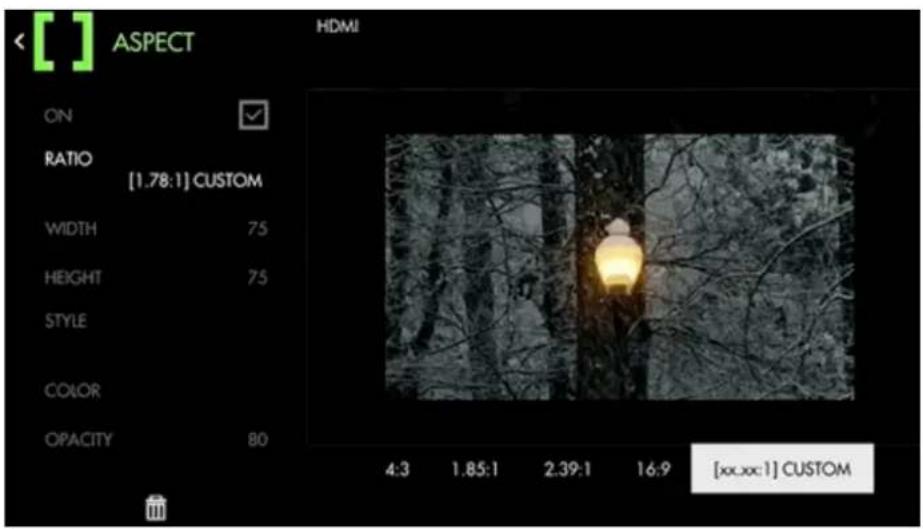
text_image
[ ] ASPECT HDMI ON RATIO [1.78:1] CUSTOM WIDTH 75 HEIGHT 75 STYLE COLOR OPACITY 80 4:3 1.85:1 2.39:1 16:9 [xx.xx:1] CUSTOMIf you are shooting in a different aspect ratio than the expected final output, place an Aspect Guide on your page for framing your shots instead of just using gaffer tape. These act like a Matte, but do not affect your footage.
Aspect - Settings
ON
Enable/Disable the Aspect guide. You can also enable or disable the tool by selecting it on the tool bar. It will be Green when enabled and Grey when disabled.
RATIO
Select the aspect ratio you wish to visualize with the guide. There are several presets that you can use. If none of these meet your needs, you can create your own with the Custom setting if using a non-

SmallHD User Manual
standard ratio.
Custom Ratio (x.xx : 1) will open two new menu options:
WIDTH - This sill translate as a % from left to right.
HEIGHT - This will translate as a % from top to bottom of the frame.
STYLE
You have two options.
MATTE - will give you "bars" over the top of the image.
LINE - Will have a 2-3 Pixel line, like a guide line, showing you the edges of the aspect you have selected.
*Line style may be more helpful when needing to see very clearly what is outside the active area as it will not get 'painted' over as it does with solid color.
Color
Define the color of the overlay area if using 'MATTE' style or define the color of the border when using 'LINE' style.
Opacity
Adjusts the opacity/transparency of the matte area or line borders depending on the chosen Style.
Aspect - Quick Start
For this example we will be preparing for a cinemascope (2.39:1) aspect ratio while filming in standard 16x9. This means we wish to visualize the top and bottom of the image being cropped for the final product via Aspect Guides.
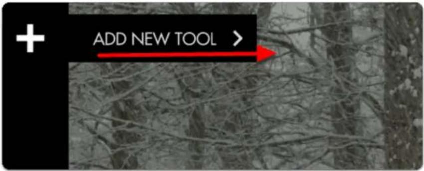
From any page, click the joystick or tap the screen on a touchscreen monitor and select 'Add New Tool'
text_image
ADD NEW TOOL >Navigate to Frame > Aspect and select the '+' to add it to the current page.
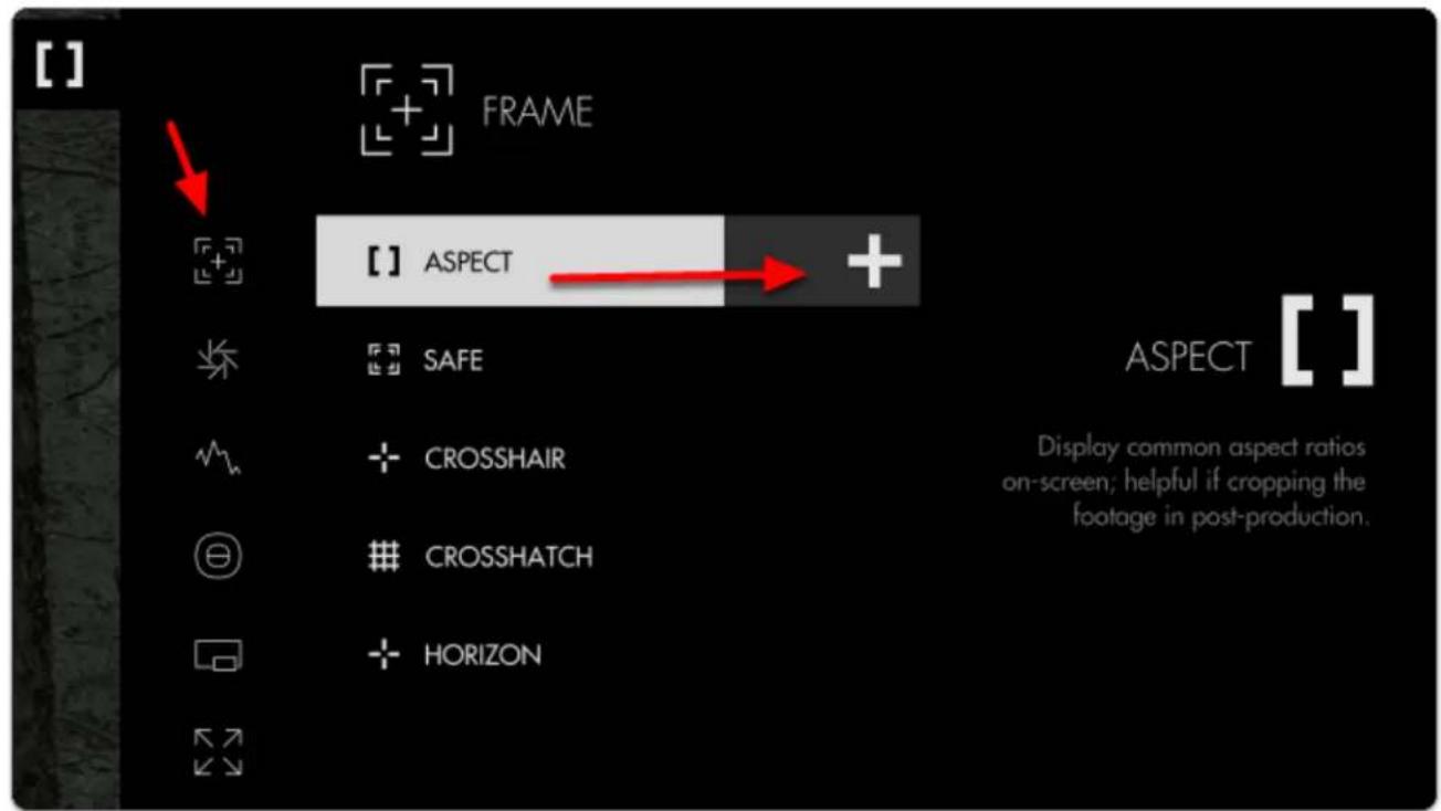
text_image
[ ] FRAME [ ] ASPECT + SAFE ASPECT [ ] Display common aspect ratios on-screen; helpful if cropping the footage in post-production. CROSSHAIR CROSSHATCH HORIZONOnce added you can edit the settings by navigating right or tapping the right arrow when 'Aspect' is highlighted.
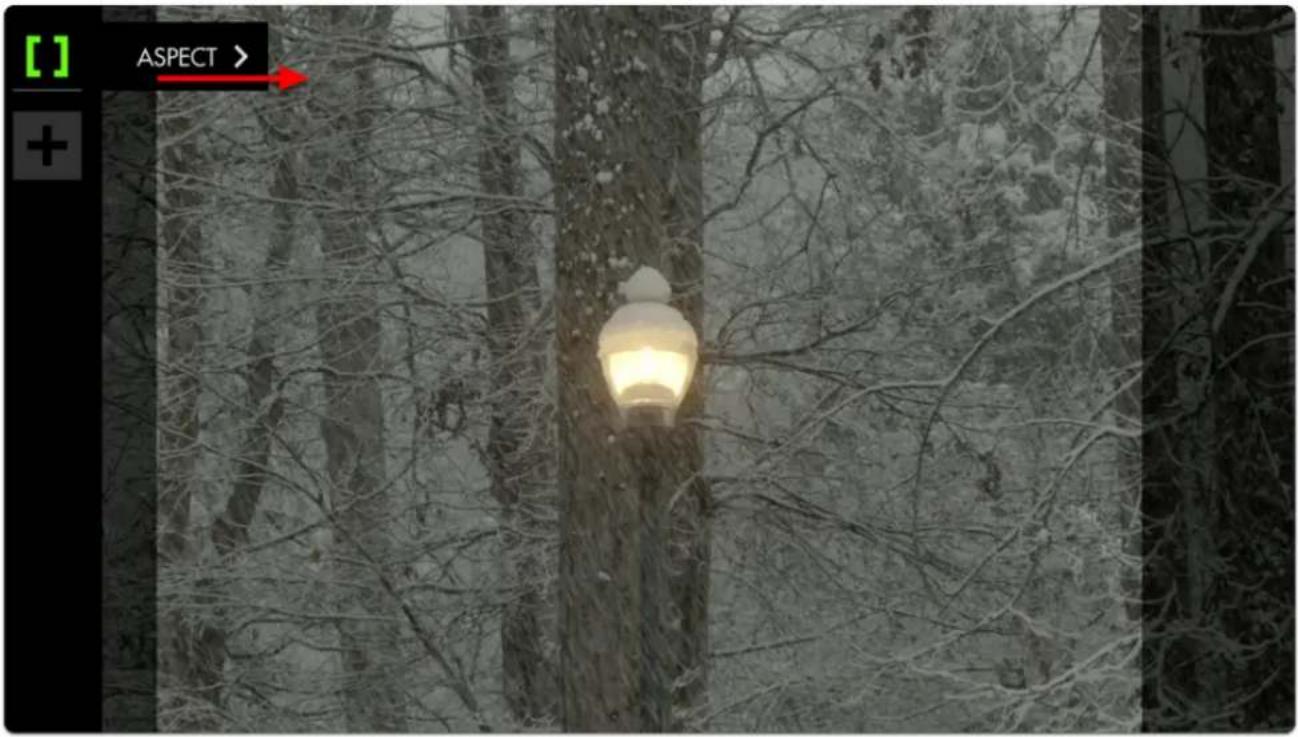
text_image
[ ] ASPECT > +The default setting is for previewing a 4:3 aspect ratio for older TVs. Select 'Ratio' and change it to 2:39 to see the black bars switch to a horizontal configuration.
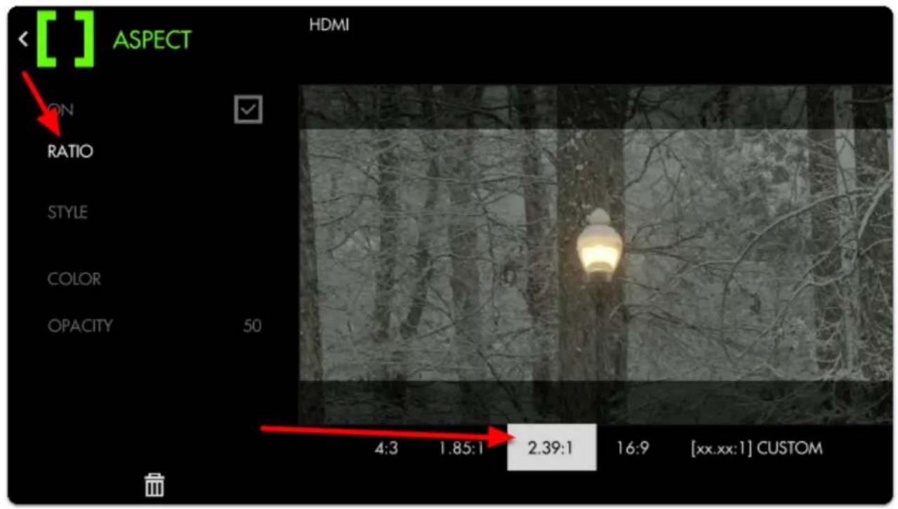
text_image
[ ] ASPECT HDMI ON RATIO STYLE COLOR OPACITY 50 4:3 1.85:1 2.39:1 16:9 [xx.xx:1] CUSTOM
SmallHD User Manual
By default the bars are set to 50% opacity; adjust 'style' and 'opacity' to taste for whatever you find most viewable. Here I set the opacity to 80% to keep the off-screen areas from being distracting.

If your production relies on boom audio, you can use the top and bottom dead zones to give your boom operator a 'grace area' for getting close-but-not-too-close.
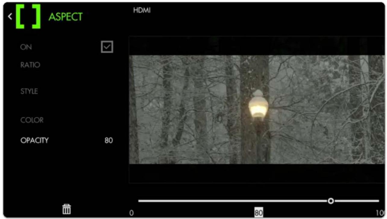
text_image
[ ] ASPECT HDMI ON RATIO STYLE COLOR OPACITY 80 0 80 10Safe (guides)

Safe
Also known as Title-safe, this tool provides a simple line border near edges of the frame as a friendly reminder to keep important elements in-frame to account for 'overscan'- some TVs will crop out part of the frame to fit various aspect ratios/resolutions being sent and title safe is still used by broadcast stations and other users not using an internet medium.
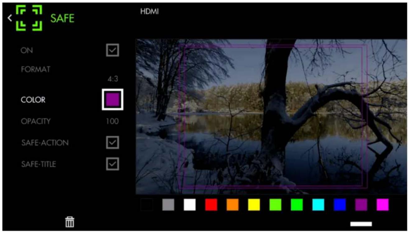
text_image
SAFE HDMI ON FORMAT 4:3 COLOR OPACITY 100 SAFE-ACTION SAFE-TITLESafe (guides) - Settings
On
Enable/Disables Safe guides. This can also be done at the tool bar level by activating or deactivating the tool. It will be Green when active and Grey wen not.
Format
Adjusts the aspect ratio of the safe guides; set this to what you consider the 'least common denominator', i.e. if you have to make a 16x9 AND a 4x3 deliverable, use the 4x3 guide to account for the 'worst case'.
*These are the two standard when it comes to Broadcast Television. If you know you will need a custom title safe area, you can use the ASPECT tool in line mode.
Color
Choose the line color of the guides for easier view-ability depending on your shot.
Opacity
Adjust the transparency/visibility of the guide lines, best practice is typically to go with 'visible but not distracting'.
Safe-Action
Enables/disables the Action safe (outside) border.
*This again dates back to broadcast, if you wanted to be sure that the crop of the panel on the TV would not interfere with your image/ or action in the frame.
Safe-Title
Enables/disables the Title safe (inside) border.
*This again dates back to broadcast, if you wanted to be sure that graphics would not interfere with your image/ or action in the frame.
Safe (guides) - Quick Start
Let's apply Safe guides to a page to help judge where to keep titles and action
From any page, click the joystick or tap the screen to bring up 'Add New Tool'.
Navigate to Frame > Safe and select to add it to the current page.
Odds are the default setup is all you will need but you can edit the settings by navigating right when 'Safe' is highlighted.
Let's change the aspect ratio to 4:3 so we can visualize how an old TV would crop our image.
If the guides are not visible in your viewing environment you can edit the Color and Opacity for better viewability.
Crosshair
Crosshair
Places a crosshair reticule in the center of your image; great reference point on shoots when symmetry or panning accuracy is an important part of the composition.
*You will need a video signal to use most tools.
Crosshair - Settings
On
Enable/Disables the Crosshair. This can also be done on the tool bar by selecting the tool and activating or deactivating it. Active tools are green, inactive are grey.
Style
You have three choices:
CROSS +
BOX □
POINT •
Color
Define the color of the Crosshair for better visibility depending on your shot.
Size
Choose the size of the Crosshair to taste for your preferred balance of visibility and cleanliness.
Opacity
Sets the transparency/opacity of the crosshair.
Crosshair - Quick Start
From any page, click the joystick or tap the screen to bring up 'Add New Tool' and navigate to Frame > Crosshair and select to add it to the current page.
A crosshair will be placed on your image. You can edit the settings by navigating right when 'Crosshair' is highlighted.
Crosshatch
Crosshatch
Also known as "Grid" this tool will overlay ta geometric grid pattern over your image with customizable rows/columns for a variety of on-set compositional needs.
Crosshatch is beneficial for aligning elements of a shot into a grid-like and structured pattern, and can also be used for frame balance/ composure.
Crosshatch - Settings
On
Enable/Disable the Crosshatch. This can also be done on the tool car by activating or deactivating the tool. It will be Green when active, and Grey when inactive.
Color
Set the line color of the Crosshatch to adjust its visibility.
Opacity
This will adjust how much you can "see through" the grid.
Regions
This setting lets you define the density of the Crosshatch grid for achieving the desired amount of granularity.
You can have 2x2
Crosshatch - Quick Start
'Add New Tool' and navigate to Frame > Crosshatch and select to add it to the current page.
Once the Crosshatch is added you can edit the settings by navigating right when 'Crosshatch' is highlighted.
The pattern is going to be a 1:1 in sections. So if you want a 3x3 (rule of thirds) it will give you 3 wide by three high which is 9 equal squares in total.
Tools - Exposure
Exposure Assist (False Color)

text_image
Exposure Assist (False Color)
natural_image
Illustration of a person in profile with green facial features, set against a stylized landscape background (no text or symbols)Exposure Assist is a highly visible, quick and accurate guide to setting exposure for your shots by 'painting' pixels when they hit a specified luma (brightness) value. This helps you pinpoint the exact areas your image may be clipping and quickly roll exposure to adjust for it, particularly in difficult viewing conditions (outdoors or on a gimbal or crane)
Exposure Assist - Overview
Use this section to compare Exposure Assist with SmallHD's other exposure tools to help you find what suits your personal preference.
Because Exposure Assist 'paints' your image different colors depending on what their luma (brightness) value is, it can be beneficial to memorize these colors to make the most sense of your exposure range.

SmallHD User Manual
Alternately you can now create your own exposure/color scale if you find the presets not to your tastes or suitable for your camera.
Exposure Assist is a very fast tool for finding proper exposure because you can simply look at your image - if a desired portion of the picture is being painted the color designated for highlights for example, that typically means you'll have to bring down the exposure to regain the detail in that area. As an example it can be used for shots that need to have an even exposure, like a keyed background (green screen).

If the colorizing effect of Exposure Assist is too distracting for your other on-set tasks, try creating a new page specifically for it so that you can flip back and forth for a quick exposure spot-check when needed.
Because the Exposure Assist scale can now be customized allowing you to map many colors to many brightness ranges, it can give you an incredibly comprehensive look at your exposure values. The Waveform only offers slightly more utility in that it can be used to gauge chrominance (color) in addition to luminance (exposure) when using Parade or RGB modes.

If you would rather look at a graph to expose your image than to have it 'painted over', have a look at the Waveform.
Because of the nature of Exposure Assist and how it paints the image various colors, it can become distracting to other necessary jobs on set. Tools like the Zebra, though less comprehensive, may work better for you. This is a simplified single spectrum IRE tool. EXPOSURE ASSIST is meant for more complicated exposure level monitoring of the image.
Exposure Assist - Settings
Access Exposure Assist's settings menu by navigating right or pressing the right arrow when the Waveform is highlighted.
On
Toggles Exposure Assist Off/On. You can also do this on the tool bar by selecting the tool and activate ot deactivating it. It will be green when active and grey when inactive.
Style
Choose from a preset exposure assist scale or start with a generic map that you can customize.
You will have the Following Options:
ARRI - R(99-100), Y(97-99), Pk(52-56), G(38-42), B(2.5-4), Pu(0-2.5)
Spectrum - Rainbow Gradient from Pink(0) to Red(0)
MAP (1,2,3) - Custom settings that you create
Edit (MAP)
You can make up to 3 different MAP styles.
You can have up to 10 different gradient selections on a single MAP setting.
The new customizable MAP allows you to really fine tune your exposure settings to your liking.
Once a MAP is selected, entering edit mode will bring up the IRE guide.
Select the [+]
This will add a line with a COLOR box, MIN value, MAX value and GRADIENT slider.
Adjusting the MIN and MAX will set your values for start and stop for that color against your exposed image.
This will be represented on the slider. Selecting the slider, you can adjust the overall position of the MIN/MAX against the overall gradient form 0-100.
Selecting the trashcan will delete that line/ color.
Once finished you can hit save to store your settings.
Ignore Look
Allows Exposure Assist to work on the signal directly from the camera even if you have a Look (3D LUT) applied as a tool on the monitor which would otherwise affect the results on the scale. Uncheck if you wish to monitor exposure values AFTER a look has been applied to see what effect it may bring to the final image.

We recommend leaving this on for most shooting scenarios unless you are baking a LUT into your footage on set and do not intend to color grade in post.
Show IRE Guide
Display a visual 'legend' to help make sense of the colors that correspond to brightness values. This is helpful as a reminder if you have a wide variety of aspects you are monitoring.
Guide Location
Set the location of the IRE guide to a spot of your choosing.
This can be moved to 6 positions on the monitor:
TOP = Left, Center, Right
BOTTOM = Left, Center, Right
Intensity
Dial in the intensity of Exposure Assist to make its effect more subtle, allowing an easier view of the original image. Dialing back the Intensity will also decrease Exposure Assist's greyscale influence, bringing saturation back into your image.
Exposure Assist - Customization
NEW with firmware version 3.0! - Continue this section to learn how to get the most out of Exposure Assist by creating your own preset (MAP).
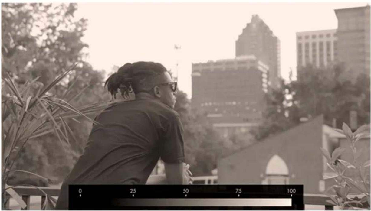
Many cameras, particularly when shooting in 'log' mode keep their brightest highlight and darkest shadow at values other than 100% and 0% respectively. Full shadow clipping might be as high as 10% and highlights might be as low as 90% for example. Customizing the Exposure Assist scale ensures these settings are tuned to your specific camera for guaranteed accuracy.
natural_image
Black-and-white photo of a man sitting on a balcony overlooking a cityscape with high-rise buildings in the background (no visible text or symbols)To begin setting the scale we need to first find the limits. For the following example I'm using a DVX200 set to V-Log gamma but this procedure applies to any camera or gamma.
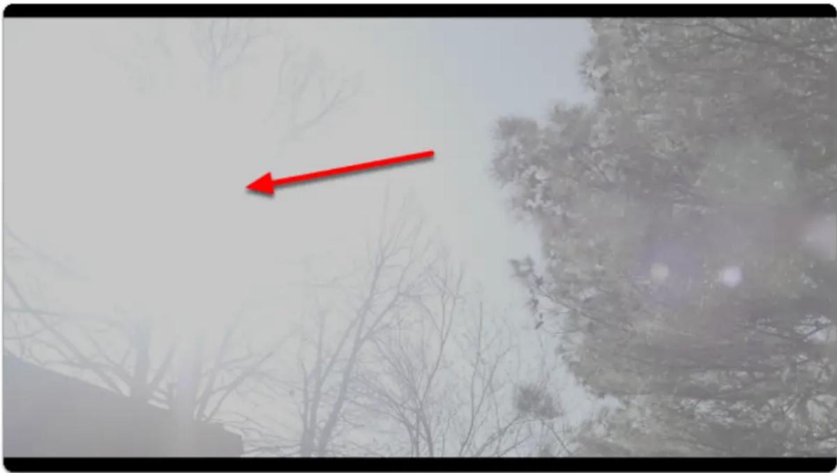
First, point the camera toward any bright objects that will overexpose the shot (a white car or exposed concrete on a bright day will do fine) - turn off ND filters, open the aperture and decrease the shutter speed if needed:
natural_image
Snowy landscape with bare trees and a red arrow pointing to a distant tree (no text or symbols)
I briefly pointed the camera towards the sun during midday for this shot - this is generally not advisable to keep the sensor safe but I did it so you don't have to ;-)
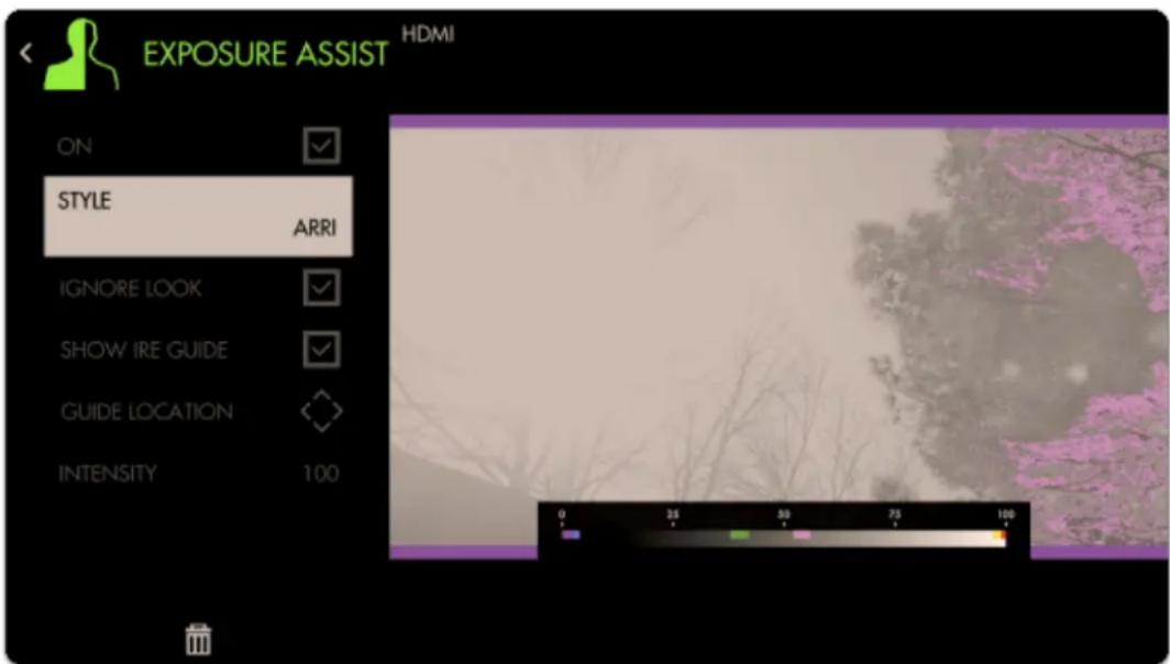
Add an Exposure Assist via Add Tool > Expose > Exposure Assist if not already applied.
text_image
EXPOSURE ASSIST HDMI ON STYLE ARRI IGNORE LOOK SHOW IRE GUIDE GUIDE LOCATION INTENSITY 100
SmallHD User Manual
Even though the sun area is clearly clipping, the Arri false color scale doesn't pick it up - we need to fix this for an accurate reading.
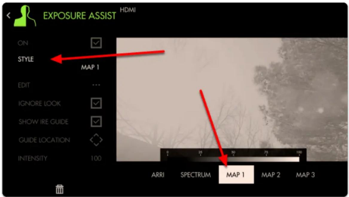
Select 'Style' and choose 'Map1' to start with an empty preset that we can modify.
text_image
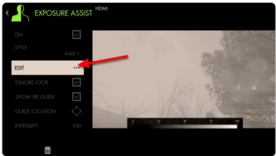
EXPOSURE ASSIST HDMI ON STYLE MAP 1 EDIT ... IGNORE LOOK SHOW IRE GUIDE GUIDE LOCATION INTENSITY 100 0 25 50 75 100 ARRI SPECTRUM MAP 1 MAP 2 MAP 3Select 'EDIT' to begin customization
text_image
EXPOSURE ASSIST HDMI ON STYLE MAP 1 EDIT ... IGNORE LOOK SHOW IRE GUIDE GUIDE LOCATION INTENSITY 100To begin adding a range, select the '+'

SmallHD User Manual

text_image
MIN MAX +A default color and range is placed onto the scale; let's change this color by selecting it
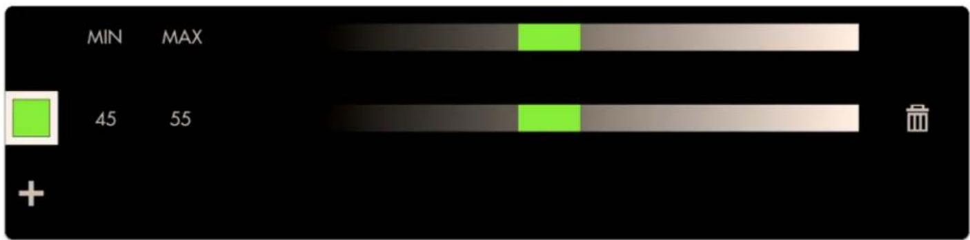
bar
| Category | Value | | -------- | ----- | | MIN | 45 | | MAX | 55 |Let's choose red to act as an overexposure clip warning.
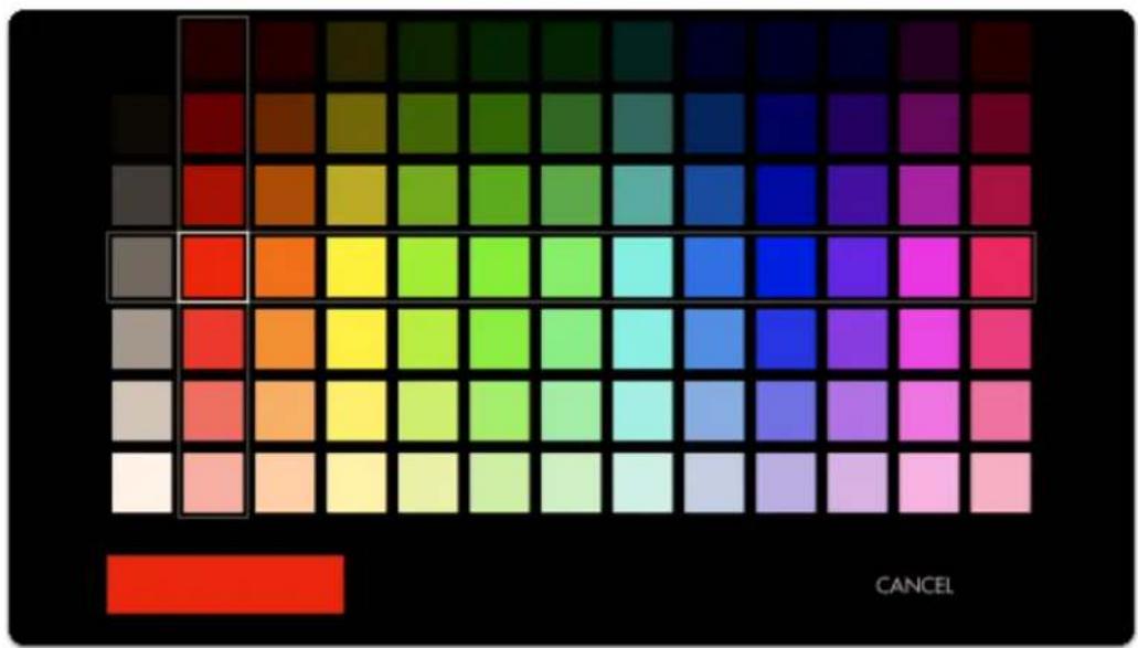
heatmap
| Color | Value | |---|---| | Dark Red | 100 | | Brown | 95 | | Olive | 90 | | Green | 85 | | Dark Green | 80 | | Dark Blue | 75 | | Purple | 70 | | Black | 65 | | Brown | 60 | | Orange | 55 | | Yellow | 50 | | Light Green | 45 | | Cyan | 40 | | Blue | 35 | | Magenta | 30 | | Pink | 25 | | Light Pink | 20 | | White | 15 | | Pink | 10 | | Light Grey | 5 | | Grey | 0 | | Red | 0 | CANCELNext we can edit the position of this color on the luminosity scale by selecting it and dragging in either direction
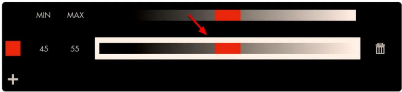
bar
| Metric | Value | |--------|-------| | MIN | 45 | | MAX | 55 |Move the color block to the far right - now any values in the 90%-100% range will get painted red. As can be seen none of the values in this image even reach 90% so we need to decrease the 'MIN' until we see a red blob appear where the sun is located.
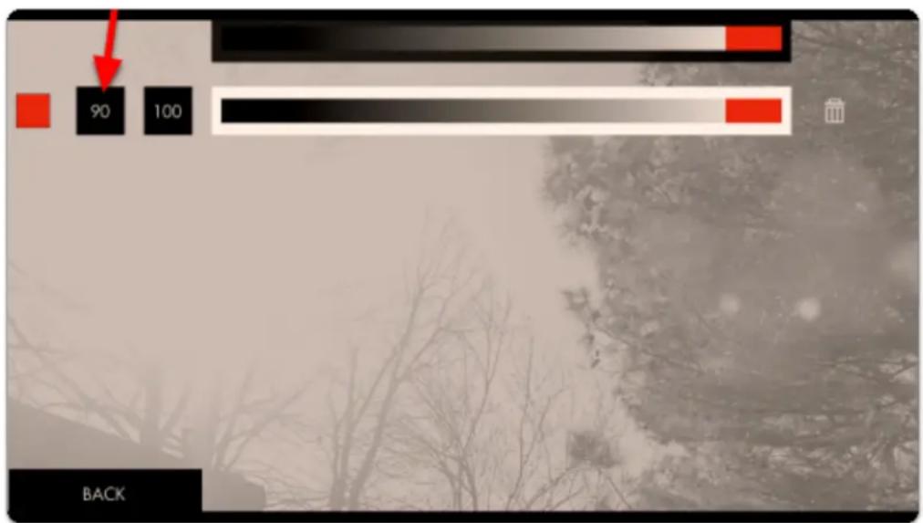
text_image
90 100 BACKWhen decreased to 80%, we have finally found the limit at which this camera clips highlights.
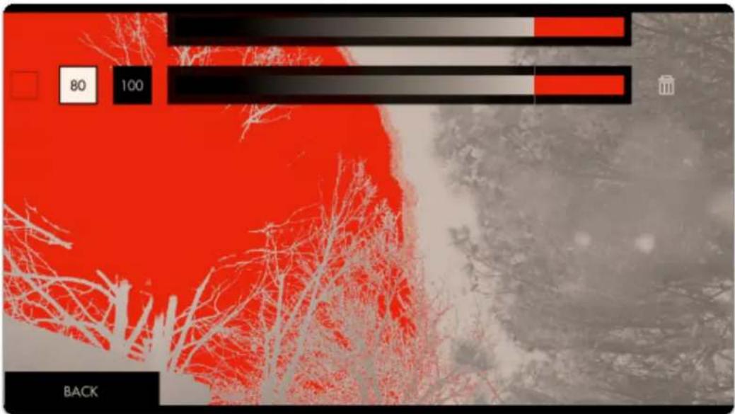
text_image
80 100 BACKThis red area is telling you 'this data is getting clipped' so let's set up another small color value immediately beside this one to act as a warning:
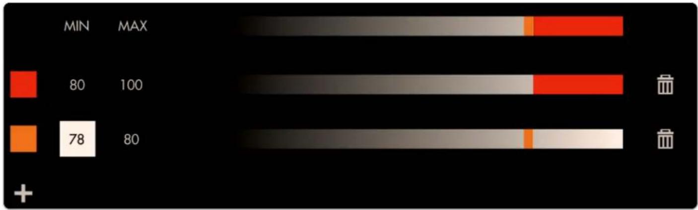
bar_stacked
| Category | MIN | MAX | |---|---|---| | Red Square | 80 | 100 | | Orange Square | 78 | 80 | The chart displays the total values for each category (MIN) and an additional value for the orange square (MAX). The red portion represents the maximum value, while the gray portion indicates the minimum value. A battery icon appears in the top-right corner. No explicit title or axis labels are provided.Now if you see orange it means you're almost clipping highlights and if you see red you are clipping highlights.
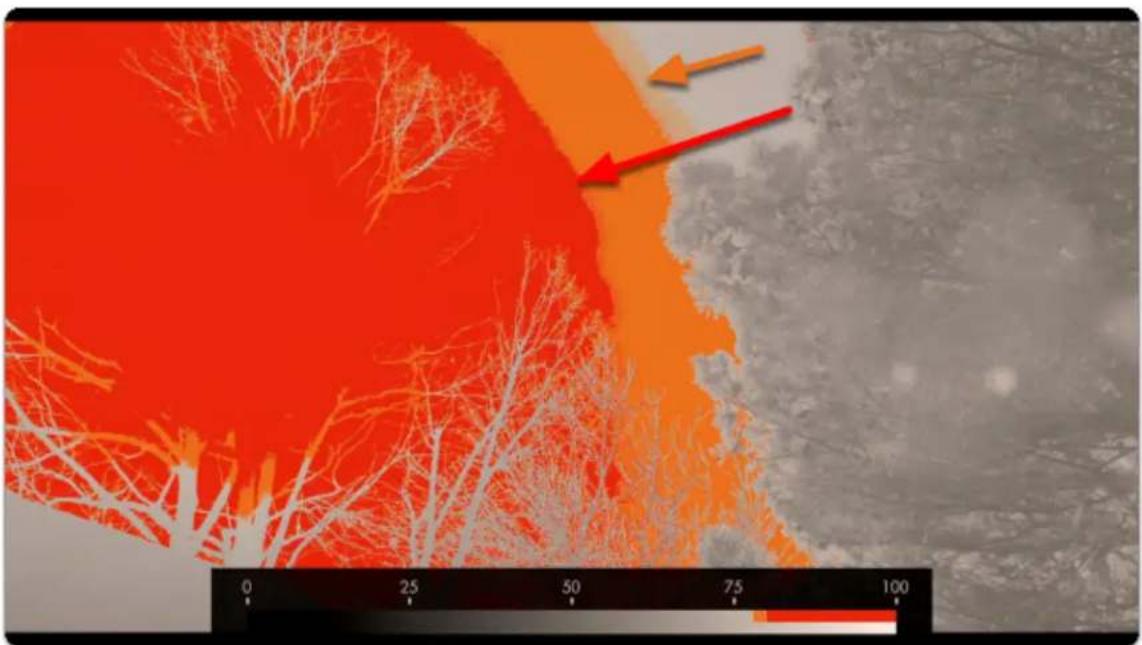
natural_image
Satellite or aerial view of a coastal area with red-orange vegetation and a scale bar at the bottom (no text or symbols on the main image)Repeat the same process but this time to the darker extremes - I have my shot set up in a dark environment but you may simply cover the lens for this stage when looking to pinpoint the camera & gamma's native black point.
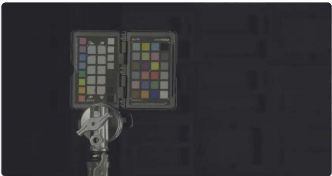
natural_image
Close-up of a camera lens and a color picker tool against a dark background (no text or symbols visible)Create a new color band for the shadows - I prefer 'cool' colors for dark areas and normally set highlights to 'warm' colors to help me identify each zone quickly but feel free to use any configuration that makes sense to you!
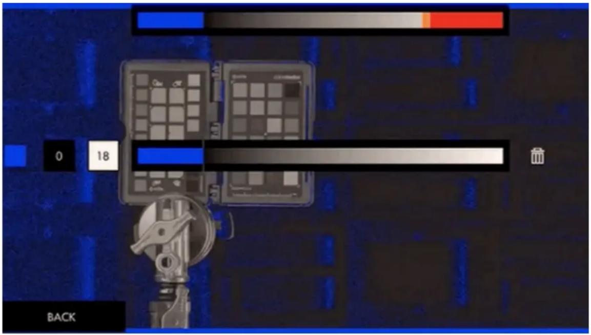
text_image
0 18 BACKSet the MIN to 0 and adjust the MAX value to the point where color starts being introduced - You can customize this value until the noise level is acceptable to you (anything that gets painted blue is considered 'clipped', so increase the MAX to 'clip' more of the noise).

Because Exposure Assist is ultimately a guide, setting these ranges is for keeping us aware of issues as soon as they show up. In this case if we see a deep blue on someone's face, we'll need to increase exposure or the footage will be noisy.
Next we can add a small 'warning zone' next to our 'clipping zone' just like with the highlights:
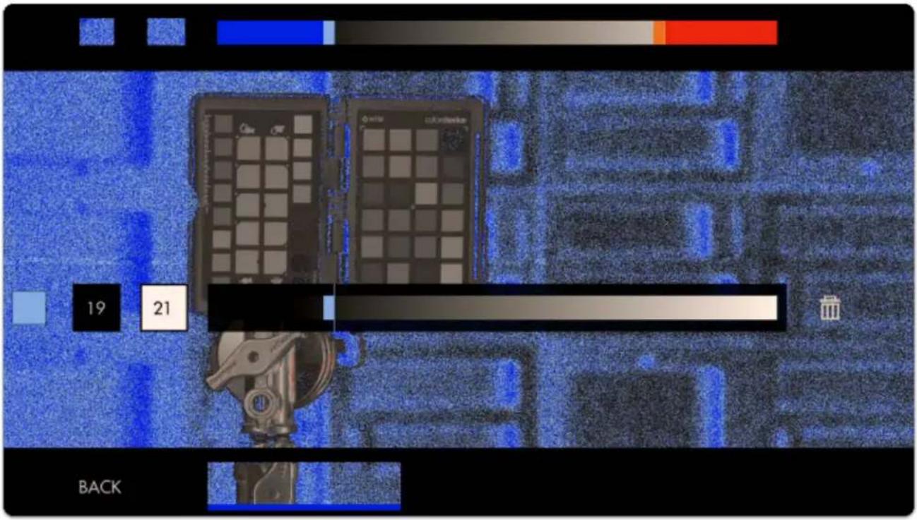
text_image
19 21 BACKThis is what our scale looks like with the upper and lower ranges applied:
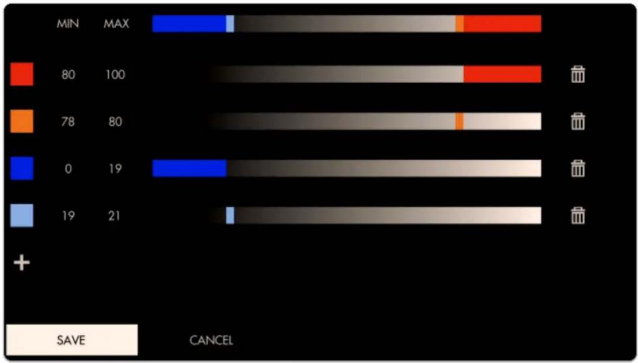
bar_stacked
| Category | Blue Segment | Orange Segment | Gray Segment | Red Segment | | -------- | ------------ | -------------- | ------------ | ----------- | | MIN | 0 | 0 | 0 | 0 | | MAX | 19 | 0 | 0 | 10 | | 80 | 0 | 0 | 0 | 0 | | 78 | 0 | 0 | 0 | 0 | | 0 | 0 | 0 | 0 | 0 | | 19 | 0 | 0 | 0 | 0 | | 19 | 21 | 0 | 0 | 0 |
SmallHD User Manual
Here is what a shot looks like when we're employing the new exposure scale. The colors reveal precisely which areas are recoverable and which are lost.
Red areas are clipped highlights, blue areas are noisy/clipped shadows.
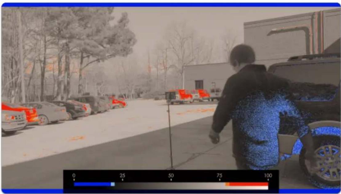
natural_image
Person walking past parked cars in a snowy urban setting, with trees and buildings in the background (no visible text or symbols)You may continue to add colors to the scale, for example a midpoint to represent skin tones or an 18% grey card/chart.
Exposure Assist - Quick Start
From any page, click the joystick or tap the screen to bring up (1) 'Add New Tool' and navigate to (2) Expose > (3) Exposure Assist and select to add it to the current page.
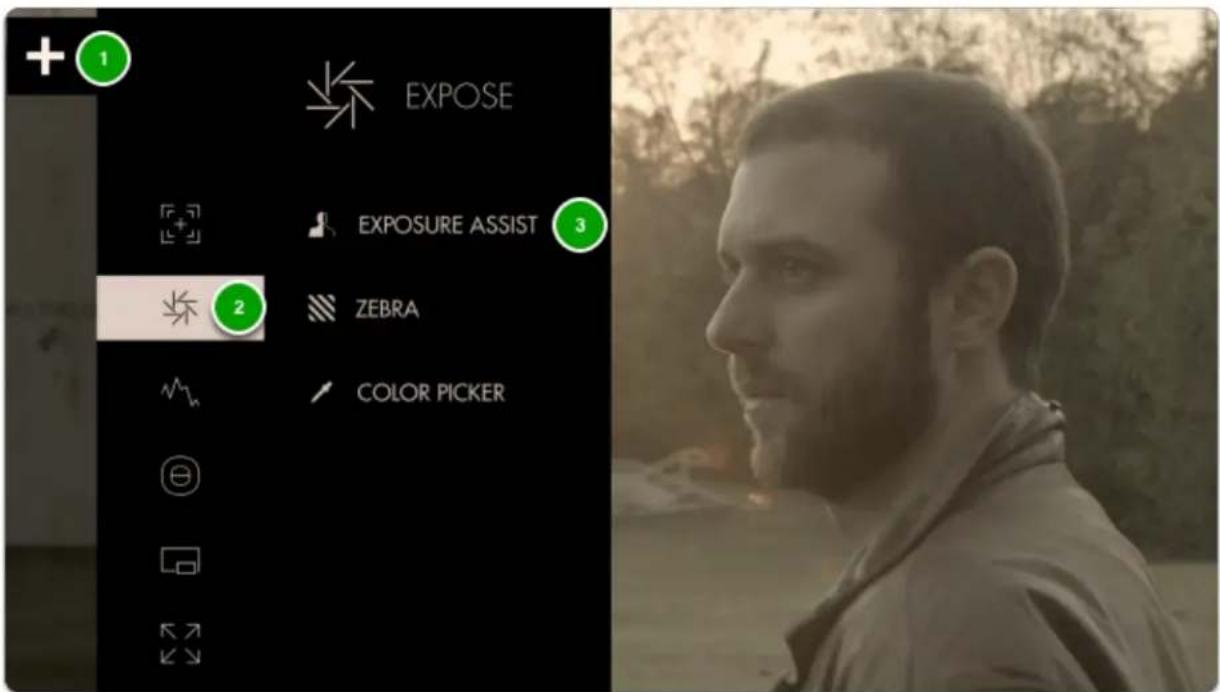
text_image
EXPOSE EXPOSURE ASSIST 3 ZEBRA COLOR PICKEROnce added you can edit the settings by navigating right or tapping the right arrow when 'Exposure assist' is highlighted.
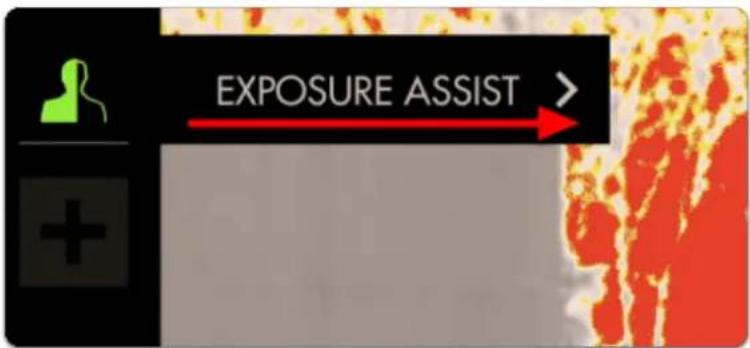
text_image
EXPOSURE ASSIST >By default the Arri False Color scale is used which is a great place to start.
You will also have the Spectrum False color, which is a gradient of color from Pink-Blue-Green-Yellow-Red. This is easily seen on the Guide bar.
You can also create your own custom set, up to 3.
The chart below describes what each color means for ARRI- essentially when an element in your scene gets colorized, that means it is within the brightness range specified here.
| Color | Level | Description |
| red | 99 – 100% | White clipping |
| yellow | 97 – 99% | Just below white clipping/white shoulder |
| pink | 52 – 56% | One stop over medium gray (Caucasian skin) |
| green | 38 – 42% | 18% neutral gray |
| blue | 2.5 – 4.0% | Just above black clipping/black slope |
| purple | 0 – 2.5% | Black clipping |
This allows you to make exposure decisions that are based on numeric values as opposed to simply how the image appears, which depending on viewing environment and many other factors can yield inconsistent results.
Enable 'SHOW IRE GUIDE' to get an on-monitor view of which values are getting mapped to the colors on the scale.
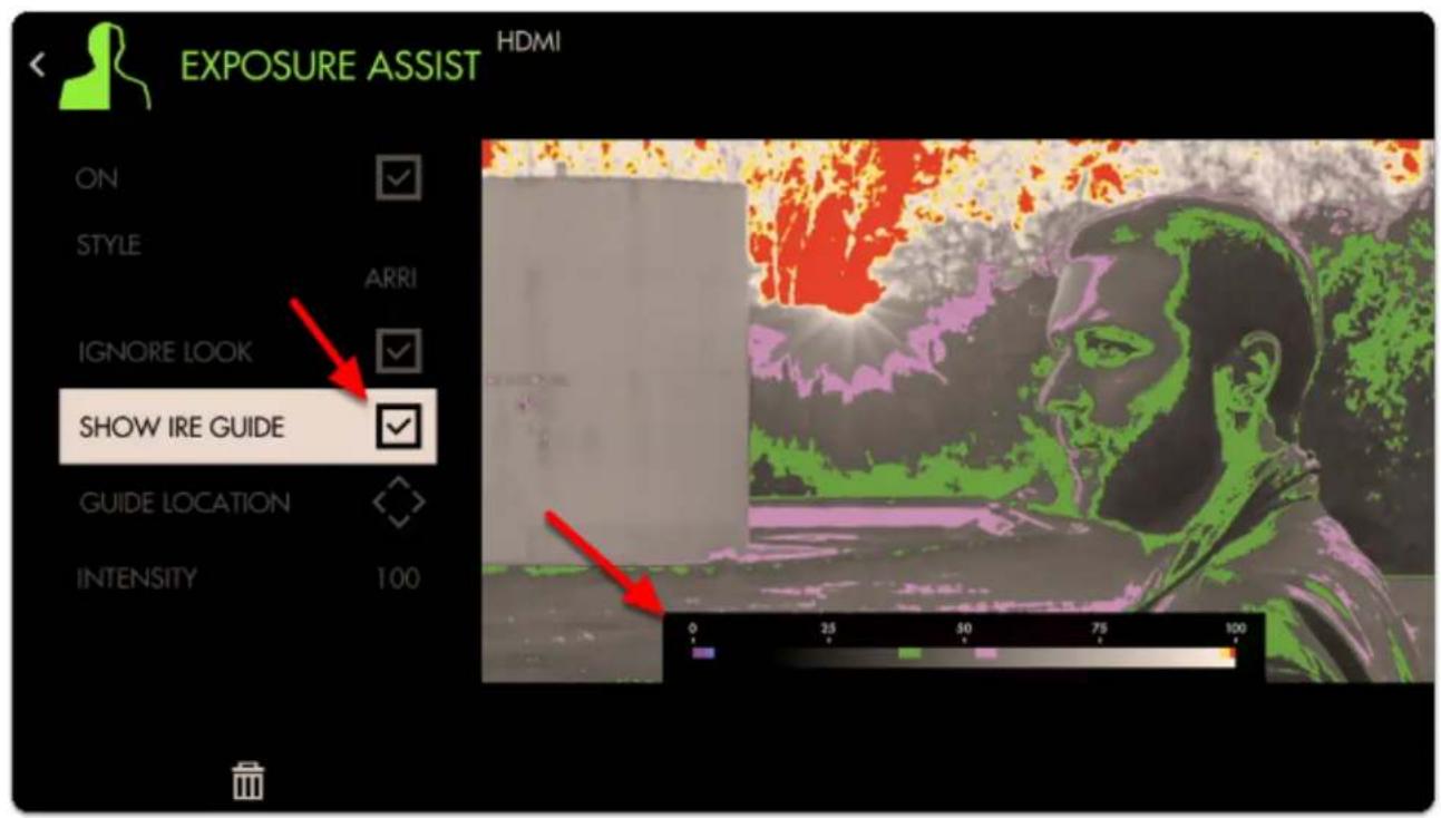
text_image
EXPOSURE ASSIST HDMI ON STYLE ARRI IGNORE LOOK SHOW IRE GUIDE GUIDE LOCATION INTENSITY 100 0 25 50 75 100Exposure values near the 50% mark on the scale will generally provide the most natural result on human skin. With the Arri scale this means the pink and green bands provide a great guide as the upper and lower range for exposing faces.
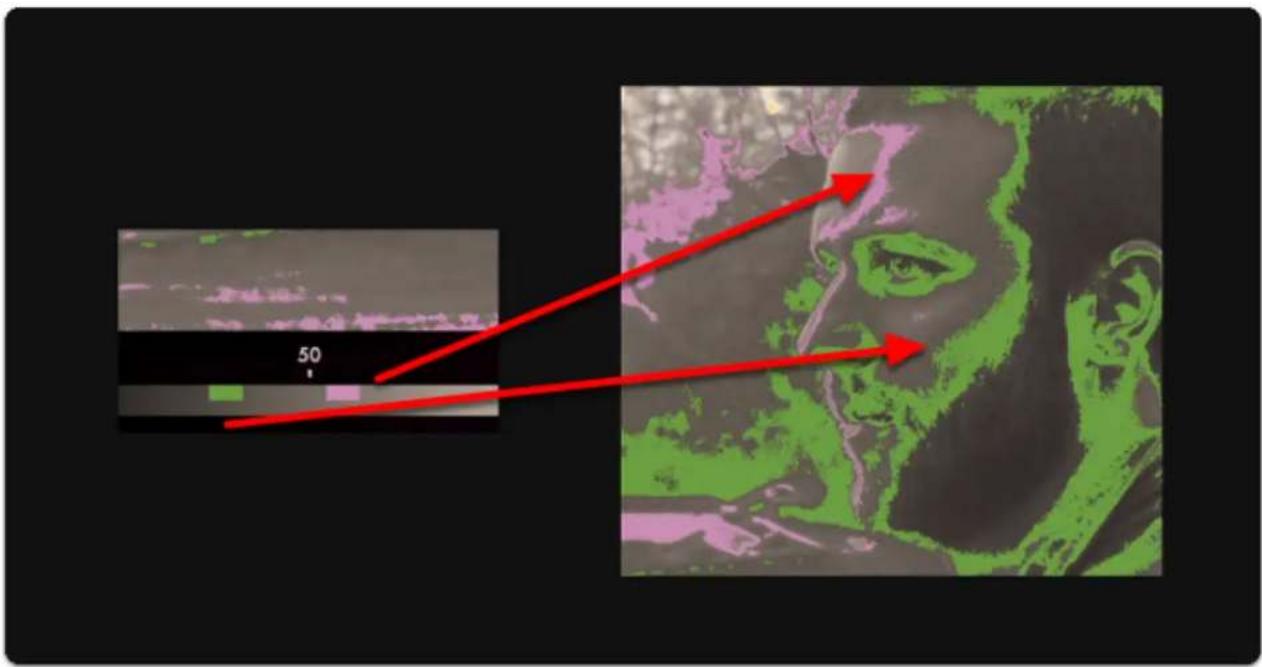
text_image
50Sticking with this exposure value means we'll be clipping a portion of the sky & sun - Exposure Assist makes it clear which areas will be clipping/losing detail as a result of overexposure by painting such areas red.
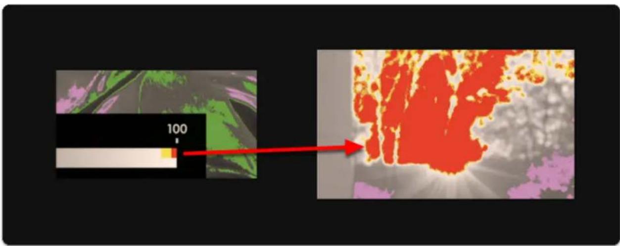
text_image
100Clipped areas are tricky to manipulate in post production because they are effectively comprised of a single 'blob' of color/value.
If I darken the entire shot, the clipped areas of the sky & sun appear quite unnatural:

SmallHD User Manual
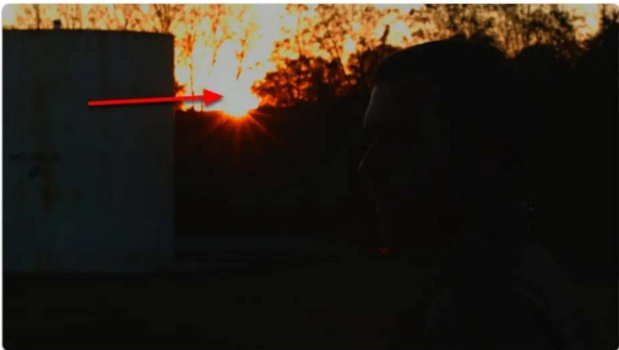
natural_image
Silhouette of a person standing at night with a red arrow pointing to the bright sun, against a sunset sky and trees (no text or symbols visible)If I darken everything but the sky/sun, they each appear much more acceptable:
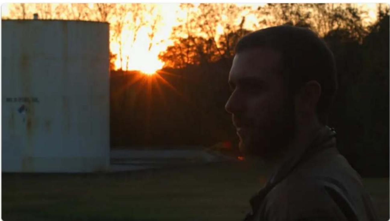
natural_image
Silhouette of a person standing outdoors at sunset with bright sun rays, no visible text or symbolsWhen graded normally, skin tones maintain plenty of detail due to being exposed in an optimal range.
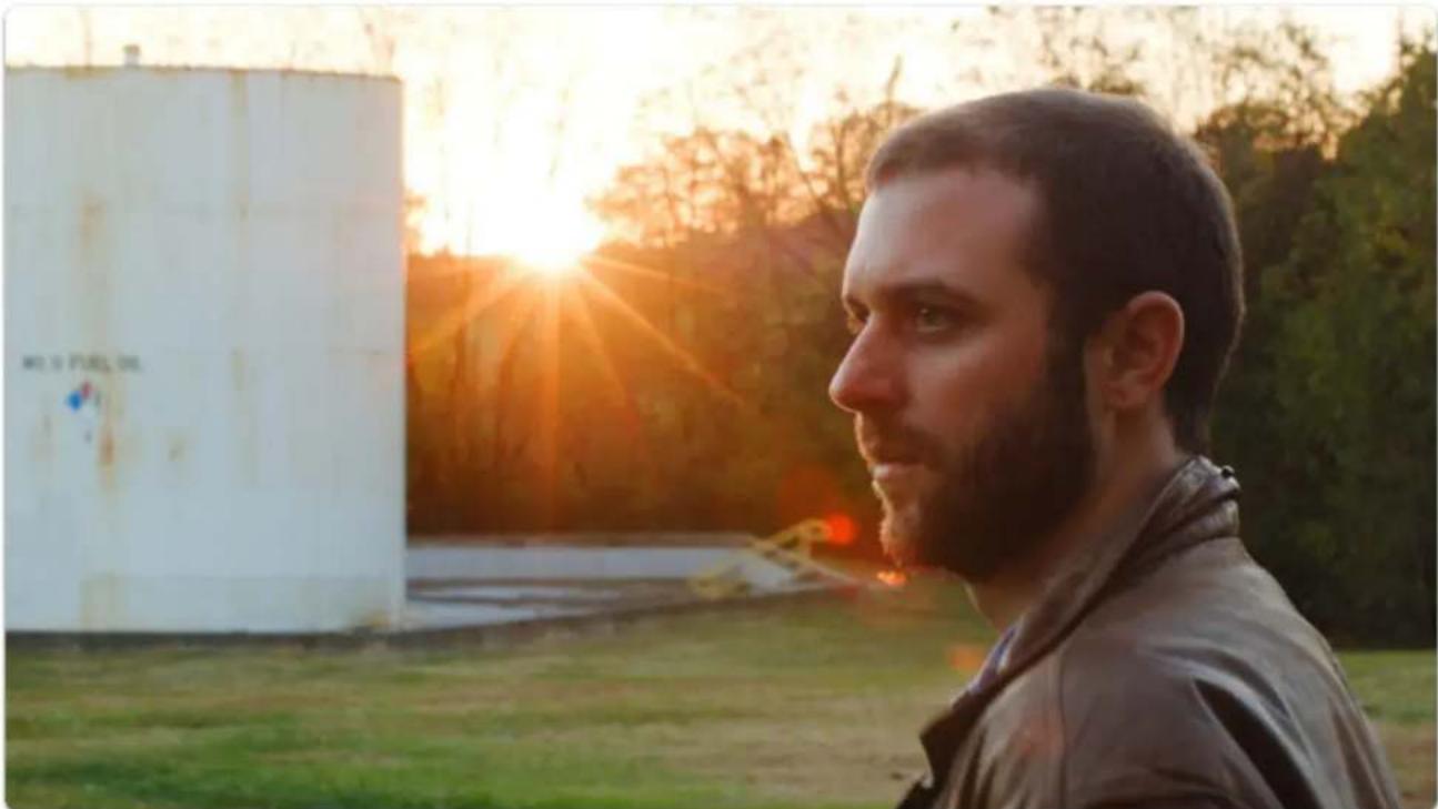
natural_image
Side profile of a man with beard looking toward a white storage tank at sunset (no text or symbols visible)Below-left is an example of normally-exposed face, below-right is an example of an underexposed face that has been brought up in color grading - take note the difference in image noise.
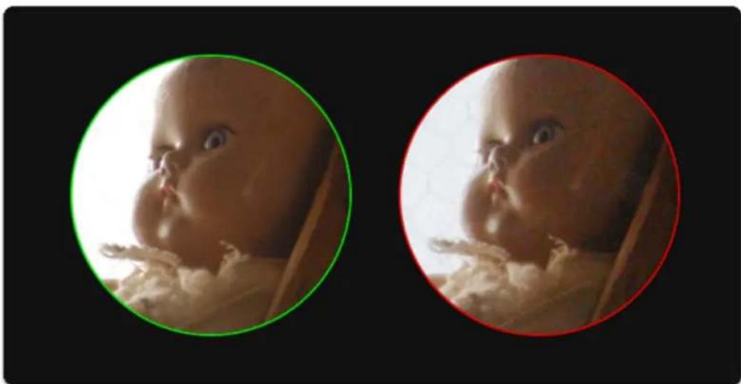
natural_image
Two circular frames showing a baby's face, one green and one red, with no visible text or symbols.Exposing a shot 'just right' will vary greatly between shoots, operators and cameras but is always a compromise in some way. You must decide how important are your highlights and shadows and what will contribute to the better final image, and this can vary depending on many elements including

SmallHD User Manual
intended color grade, delivery methods, VFX and of course the camera itself - some handle highlights better than shadows for example, others vice-versa.
Zebra

text_image
Zebra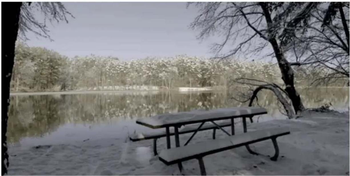
natural_image
Snow-covered park scene with a table and tree, reflected in calm water (no text or symbols visible)Similar to Exposure Assist, the Zebra tool helps you monitor exposure to your image properly by displaying a stripe pattern (sometimes called marching ants) over a specific brightness range (IRE) on your image.
This is useful for essentially setting exposure 'boundaries' typically for highlights but you can add one for shadows as well; as soon as a value hits the range you specify, a zebra pattern is displayed on that portion of the image to warn you of over or under exposure if desired.
Zebras - Overview
The Zebra tool acts on only one brightness range at a time (maximum of 2 instances of Zebra allowed simultaneously) AND it doesn't desaturate the image like Exposure Assist.
If set to the proper range, In many cases using the Zebra tool is as fast as rolling the iris until you don't see -- or see the appropriate amount of -- zebra stripes. If the zebra pattern effect is still too distracting

SmallHD User Manual
for your other on-set tasks, try creating a new page specifically for it so that you can flip back and forth for a quick exposure spot-check when needed.

If you would rather look at a graph to exposure your image than to have it 'painted over', have a look at the Waveform.
Zebra - Settings
Access Zebra tool settings menu by navigating right or pressing the right arrow when Zebra is highlighted in the tool list.
On
Toggles Zebra Off/On. This can also be done on the tool bar by selecting the tool and activating or deactivating it. It will be Green when active and Grey when inactive.
Min IRE
Sets the minimum IRE (brightness value) that will activate the Zebra functionality. This will be the exposure you will 'start" to see the stripes.
Max IRE
Sets the maximum IRE (brightness value) that will activate the Zebra functionality. This will be where the 'stripes' will stop showing.
Color
Choose the background color of the zebra pattern - adjust for visibility in difficult viewing conditions such as outdoors or on a jib/gimbal.
Ignore Look
When using a Look (3D LUT) file, you may want to enable this feature which applies the zebra tool to the original picture coming into the monitor and ignores the applied 3D LUT which would alter the points at which the tool would activate. This is important because it allows you to adjust for the original shot, giving you the most flexibility in post.
*We recommend keeping this option activated unless you plan to apply a Look/3D LUT directly to your footage in post without any additional adjustments before exporting.
Zebra - Quick Start
In this section we will add a Zebra to a page and customize it to use as a functional exposure aid.
Here we have a shot that is overexposed; we can use the Zebra tool to determine what we need to do to compensate for it and by how much.
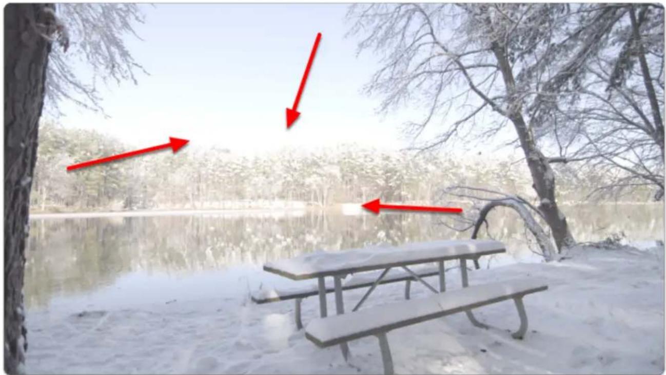
natural_image
Winter scene with a table and snow-covered water, surrounded by bare trees and a tree (no text or symbols visible)From any page, click the joystick or tap the screen to bring up 'Add New Tool'

SmallHD User Manual
Navigate to Expose > Zebra and select the '+' to add it to the current page.
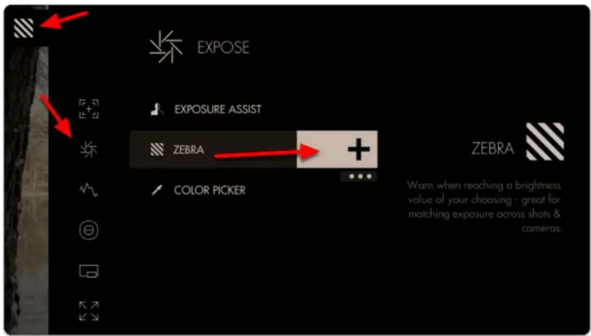
text_image
EXPOSE EXPOSURE ASSIST ZEBRA COLOR PICKER ZEBRA Warn when reaching a brightness value of your choosing - great for matching exposure across shots & cameras.We don't see any effect yet because the Zebra tool only activates by default on 100% brightness and above (confusingly, luma values can reach below 0% and above 100%).
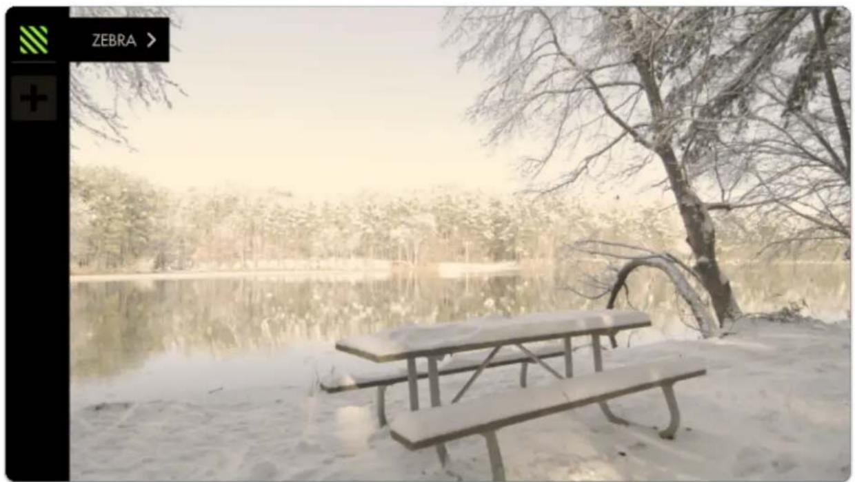
natural_image
Snow-covered park scene with a wooden bench and bare trees reflected in the water (no text or symbols visible)
SmallHD User Manual
Because our camera places its overexposure limit below 100% or 100 IRE (quite common when shooting in log/flat gammas) we need to adjust the minimum IRE until the Zebra is activated.
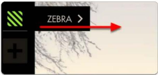
text_image
ZEBRA >You can edit the settings by navigating right (tap the arrow on touchscreen) when 'Zebra' is highlighted.
Now decrease the 'MIN IRE' setting until you can see a zebra pattern being painted over the brightest portion of your image.
This adjustment will vary between cameras/gammas.
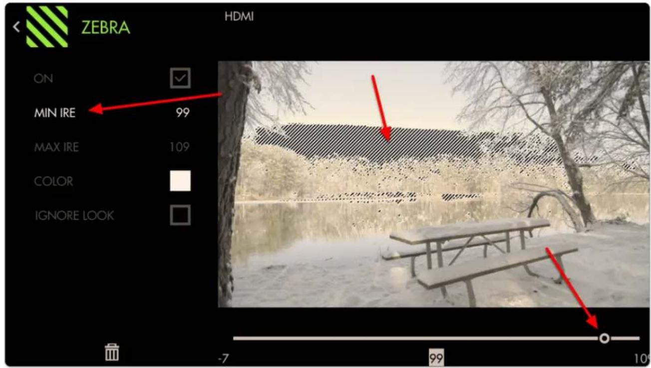
text_image
ZEBRA HDMI ON MIN IRE 99 MAX IRE 109 COLOR IGNORE LOOK -7 99 10The zebra pattern is now informing us the exact area on our image that the camera clips highlights; this marks the 'top end' of our dynamic range. From now on if we see a zebra pattern, we know for sure that the shot is being overexposed in that portion of the frame.

Bright objects, lights, sun often need to be overexposed and will display a zebra pattern in these cases.
If you wish to make the Zebra pattern more visible (purely cosmetic) you can change the color of the highlighted area. I have changed mine to red to make a very distinct overexposure warning area.
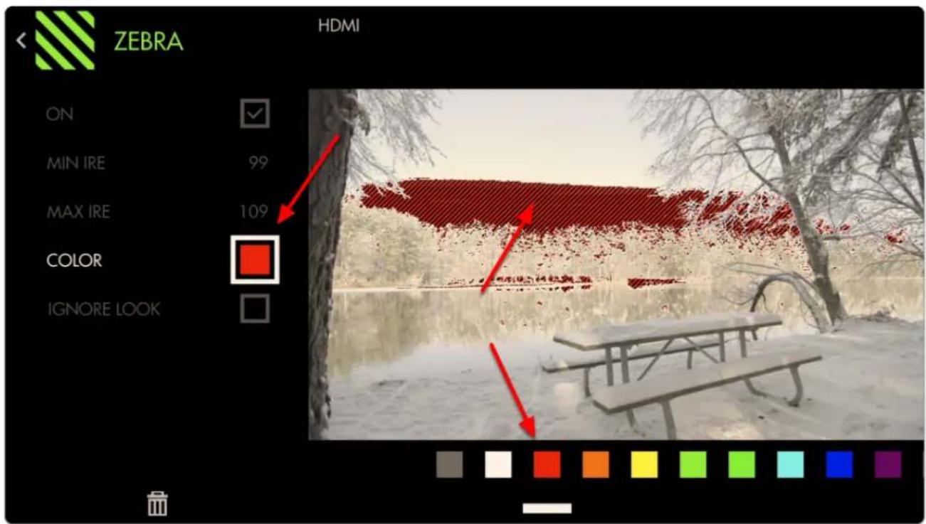
text_image
ZEBRA HDMI ON MIN IRE 99 MAX IRE 109 COLOR IGNORE LOOKAt this stage we can roll exposure down, add an ND filter, decrease ISO or increase shutter speed to darken the image until the zebra pattern is no longer visible to get highlight detail back.
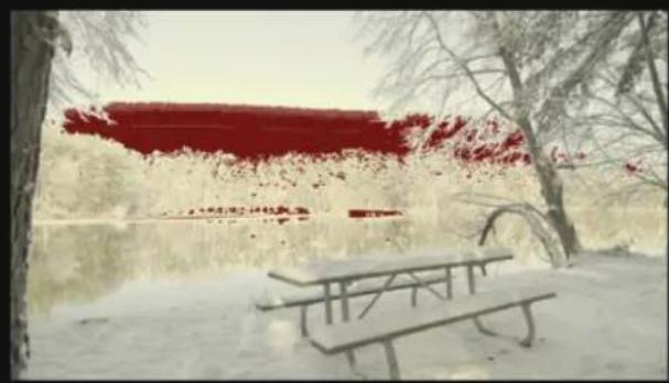
natural_image
Snow-covered park scene with a wooden bench and bare trees, no visible text or symbolsOverexposed
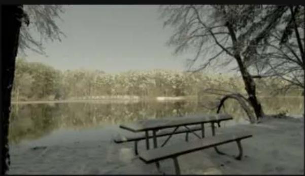
natural_image
Pound of a wooden bench by a calm lake, surrounded by bare trees and distant forest (no text or symbols visible)Normal exposure
At this point you may wish to add a second Zebra tool and set its range to shadow areas to act as exposure 'boundaries' to help maximize dynamic range.
Here we place the MIN IRE at its lowest possible setting then set the MAX IRE to 0 and increase if necessary until pitch-black shadow areas activate the filter.
Feel free to place a lens cap on your camera to gauge what it considers pitch black.
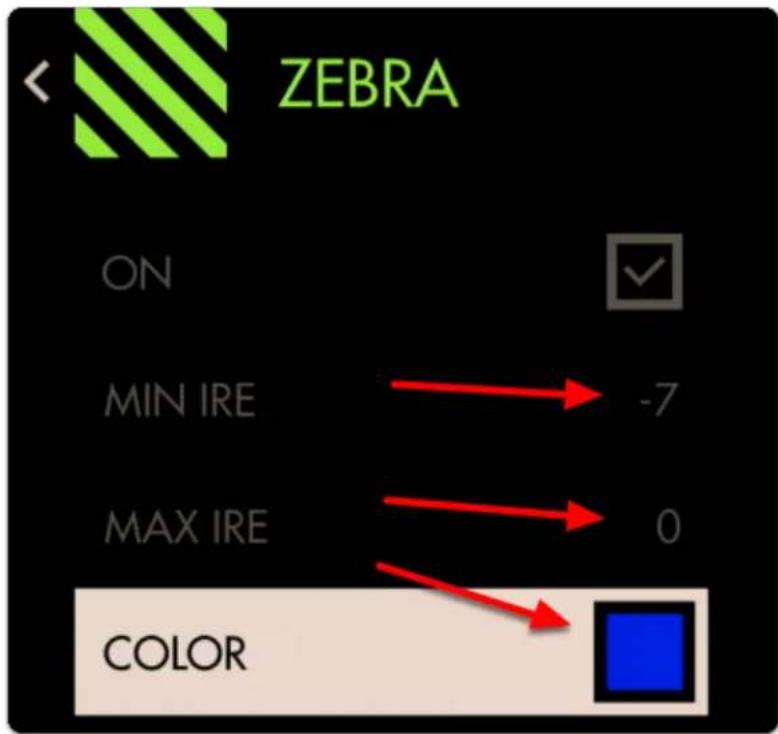
text_image
ZEBRA ON MIN IRE -7 MAX IRE 0 COLOR
natural_image
Winter outdoor scene with a wooden bench and bare trees, no visible text or symbolsOverexposed
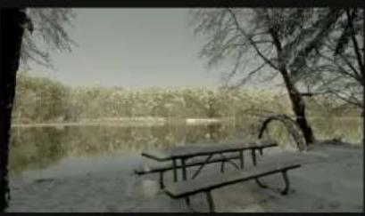
natural_image
Snowy outdoor scene with a wooden bench and bare trees near a calm lake (no text or symbols visible)Normal exposure
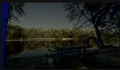
natural_image
Landscape photo of a calm lake with trees and a small table, no visible text or symbolsUnderexposed
Now we have a page configured to warn us when we are overexposing and when underexposing our footage. Anything in these areas will be clipped so you can now adjust for these limits consistently and precisely.
Because the Zebra tool doesn't activate on parts of the image outside the specified ranges, it combines well with other tools such as a Focus Assist or Frame Guides without the screen becoming too cluttered.
Color Picker

text_image
Color Picker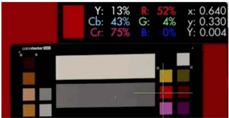
text_image
Y: 13% R: 52% x: 0.640 Cb: 43% G: 4% y: 0.330 Cr: 75% B: 0% Y: 0.004Color Picker samples color/value information from a single pixel to give a precise readout of a specific location. Great for matching multiple cameras or getting consistent exposure in changeable lighting conditions by sampling from a color chart or an actor/subject's face.

The Color Picker is unique in that it doesn't remain active when not in use, meaning when the tool is activated, moving the joystick will move the crosshair around the image and not flip through pages. To freely move between pages, disable the Color Picker. You must have a video signal to use this tool.
Color Picker - Overview
The Color Picker is easily placed anywhere on the image moving the joystick or tapping on the touchscreen for a quick select and then touch hold and scrolling with your finger for more delicate movement around the screen. Making judgements based on the data will depend on the user's preference.

An example use case for the color picker is placing the sampler on a mid grey card before every take during changing weather conditions. Roll exposure to keep the values matched for consistent exposure throughout the day.
Speed is not where the Color Picker shines for setting exposure if you need to keep an eye on several areas simultaneously - for the fastest exposure tools we recommend Zebra, Exposure Assist or the Waveform if you prefer a scope. (Scroll speed is adjustable, but this is a very precise tool).
The Color Picker serves exposure decisions that can be made from a single point such as a human face or a color chip on a test chart. To gauge a slightly wider area, have a look at the Spot Meter function of the Waveform.
The Color Picker displays only a crosshair and a popup containing some information on the pixel that's being highlighted so it keeps a relatively low profile, allowing other imaging decisions to be made without too much on-screen distraction.
Color Picker - Settings
On
Toggles Color Picker Off/On. This is also done on the tool bar by selecting the tool. It will be Green when it is active and Grey when it is not.
Format
Choose how you wish to display brightness ranges:
PERCENT - (%)
RAW - image value which will change depending on bit depth (8-bit is 0-255, 10-bit is 0-1023, etc).
Location
Set the location of the on-screen display to a spot of your choosing for best readability or to make room for the crosshair itself. You have 6 positions:
TOP - Left, Center, Right
BOTTOM - Left, Center, Right
Color
Adjusts the color of the crosshair for easier viewability.
Joy Speed
Adjusts the speed at which the color picker crosshair will glide across the screen when moved.
Color Picker - Quick Start
In this section we will add a Color Picker to a page and use it to set exposure in differing lighting conditions using a calibration chart.
From any page with a video feed, click the joystick or tap the screen to bring up 'Add New Tool'.
Navigate to Expose > Color Picker and select to add it to the current page.
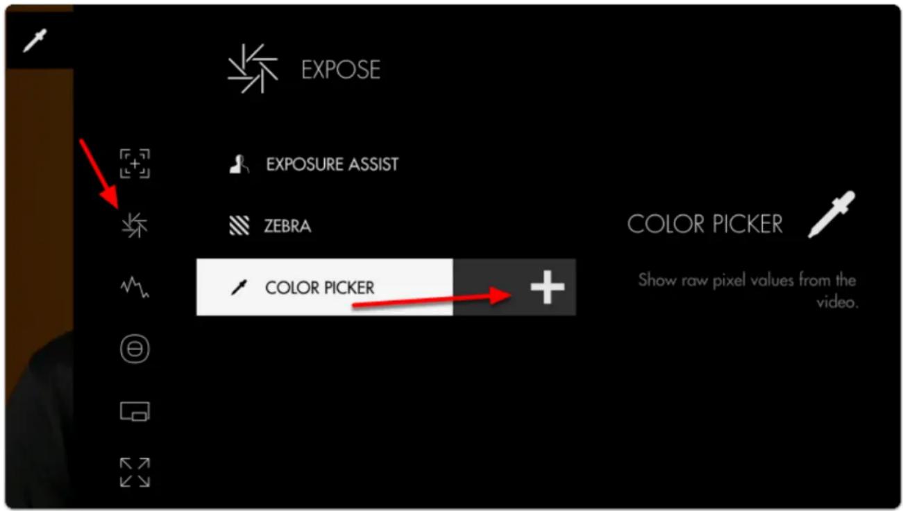
text_image
EXPOSE EXPOSURE ASSIST ZEBRA COLOR PICKER Show raw pixel values from the video.A stats window and crosshair populate the window; if we move the joystick or tap the screen we can change the point currently being sampled.
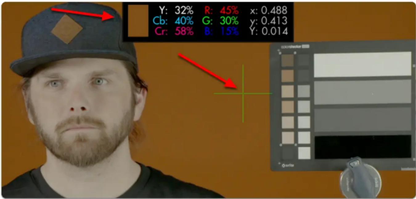
text_image
Y: 32% R: 45% x: 0.488 Cb: 40% G: 30% y: 0.413 Cr: 58% B: 15% Y: 0.014Set the crosshair on a point on the image that you wish to get a precise reading from. In my case I will pick the middle grey chip on an X-Rite ColorChecker Video chart.
This enables us to set consistent exposure shot-to-shot, resulting in less work fixing levels in post.
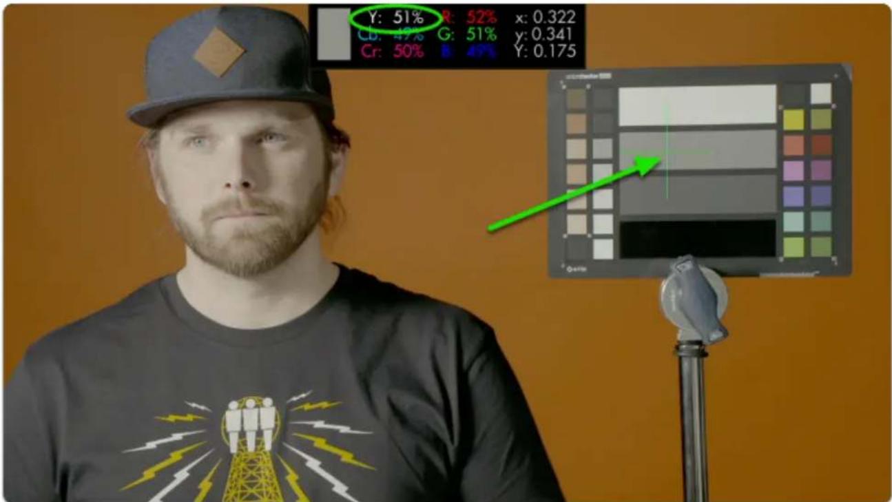
text_image
Y: 51% Cb: 49% G: 51% Y: 0.341 Cr: 50% B: 49% Y: 0.175This particular color chip has been designed to read as 'middle grey'. Look for the 'Y' (luma/brightness) percentage and roll exposure until it reads near 50%.
Changing the light setup means our exposure gets thrown out of its proper range:
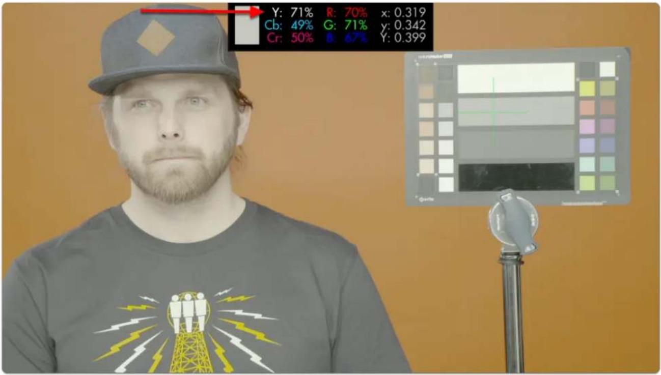
text_image
Y: 71% R: 70% x: 0.319 Cb: 49% G: 71% y: 0.342 Cr: 50% B: 67% Y: 0.399To compensate all we need to do is roll (close) the iris until we get back to the same value from before.
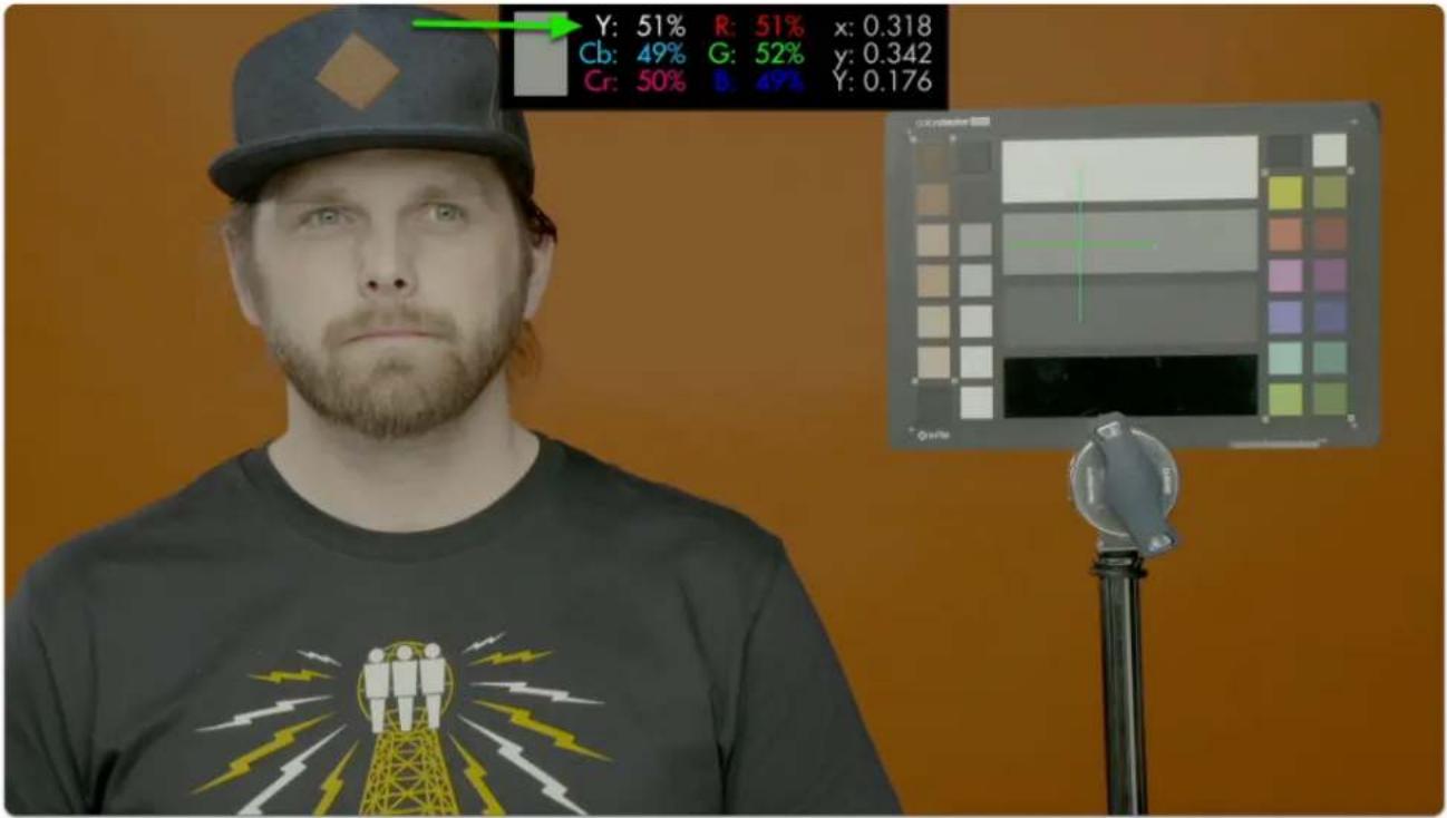
text_image
Y: 51% R: 51% x: 0.318 Cb: 49% G: 52% y: 0.342 Cr: 50% B: 47% Y: 0.176
SmallHD User Manual
Using the same technique we can adjust for exposure under any lighting condition and arrive at a clean result that will give us consistent, gradeable footage!
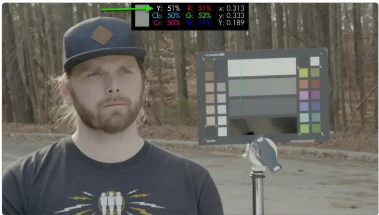
text_image
Y: 51% R: 51% x: 0.313 Cb: 50% G: 52% y: 0.333 Cr: 50% B: 51% Y: 0.189Tools - Scopes
Histogram

text_image
Histogram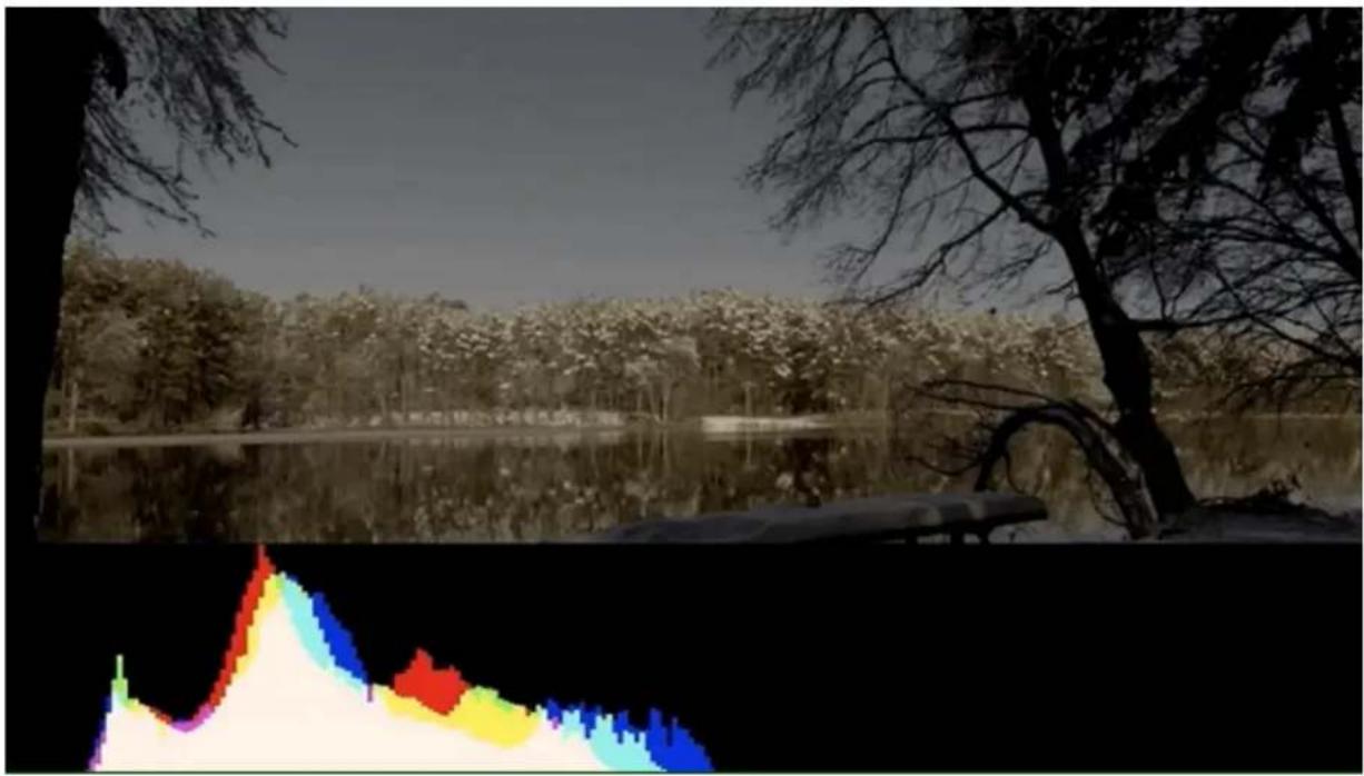
natural_image
Scenic lakeside view with trees and a reflective water surface, no visible text or symbolsThe Histogram is a brightness graph - left side is darker values, right side brighter. Use it to judge the overall balance of exposure in your image.
Histogram - Overview
Determining where your exposure is balanced is simple with the Histogram- if a 'lump' is shifting more to the left, more of your image is in shadow, if a 'lump' is towards the right, your image is largely in highlight.
One quick glance of the Histogram is enough to determine the overall exposure balance of your image -- not fine details about it but a general gauge of where most of your image is 'weighted'.

SmallHD User Manual
Beyond determining exposure balance, the Histogram is outclassed in utility by the other exposure aids that are more suitable for pinpointing specific issues on the image. For the most versatile scope for most setups, have a look at the Waveform.
The Histogram is a good low-profile scope as it doesn't generally lose any utility by being scaled down and mostly out of the way.
Histogram - Settings
On
Toggles Histogram Off/On. This can also be done on the tool bar by selecting the tool and either activating or deactivating it. It will be Green when active and Grey when inactive.
Style
Pick your flavor of Histogram-
LUMA - displays a brightness/luma plot only
RGB - displays Luman, red, green and blue values individually for a look at the chromaticity of the image.
Full Screen
Displays the histogram in a full-screen view, which is useful when viewing from a distance or if using multiple monitors where another can be displaying the image itself.
Width
Scales the Histogram horizontally to help with rearranging your workspace.
Height
Scales the Histogram vertically.
Location
Set the location of the Histogram to a spot of your choosing - useful when placing multiple tools/scopes on screen.

SmallHD User Manual
There are 9 locations to place the Histogram field:
TOP - Left, Center, Right
MIDDLE - Left, Center, Right
BOTTOM - Left, Center, Right
*(Full Screen is another option)
Opacity
Adjusts the transparency of the black background behind the Histogram for readability. Boosting Intensity helps to compensate for a lower Opacity.
Ignore Look
Because monitoring with a Look (3D LUT) alters the image and therefore its exposure, it can be useful to ignore its effects on exposure tools. This means you can monitor with any graded Look while using the Histogram to set up your camera to be exposed properly for any other grading possibilities in post because it's working off the camera's original ungraded image.

We recommend leaving this on for most shooting scenarios unless you are baking a LUT into your footage on set and do not intend to color grade in post.
Histogram - Quick Start
In this section we will add a Histogram to a page and use it to set exposure.
From any page with a feed, click the joystick or tap the screen to bring up 'Add New Tool'
Navigate to Scopes > Histogram and select the '+' to add it to the current page.
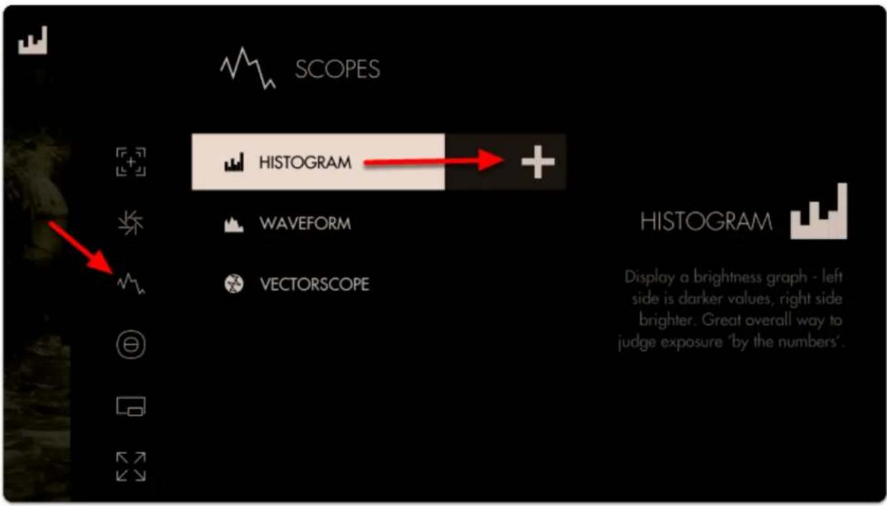
text_image
SCOPES HISTOGRAM WAVEFORM VECTORSCOPE HISTOGRAM Display a brightness graph - left side is darker values, right side brighter. Great overall way to judge exposure 'by the numbers'.A graph appears in the top-right of the image. It will default to LUMA values (Overall Exposure). Histograms read Shadow levels on the left and Highlights on the right. The weight of the curve will tell you where your exposure values are falling along that scale.
The overall 'weight' of the image data is positioned towards the left of the graph; this is telling us we have a lot more shadow areas than highlight areas.
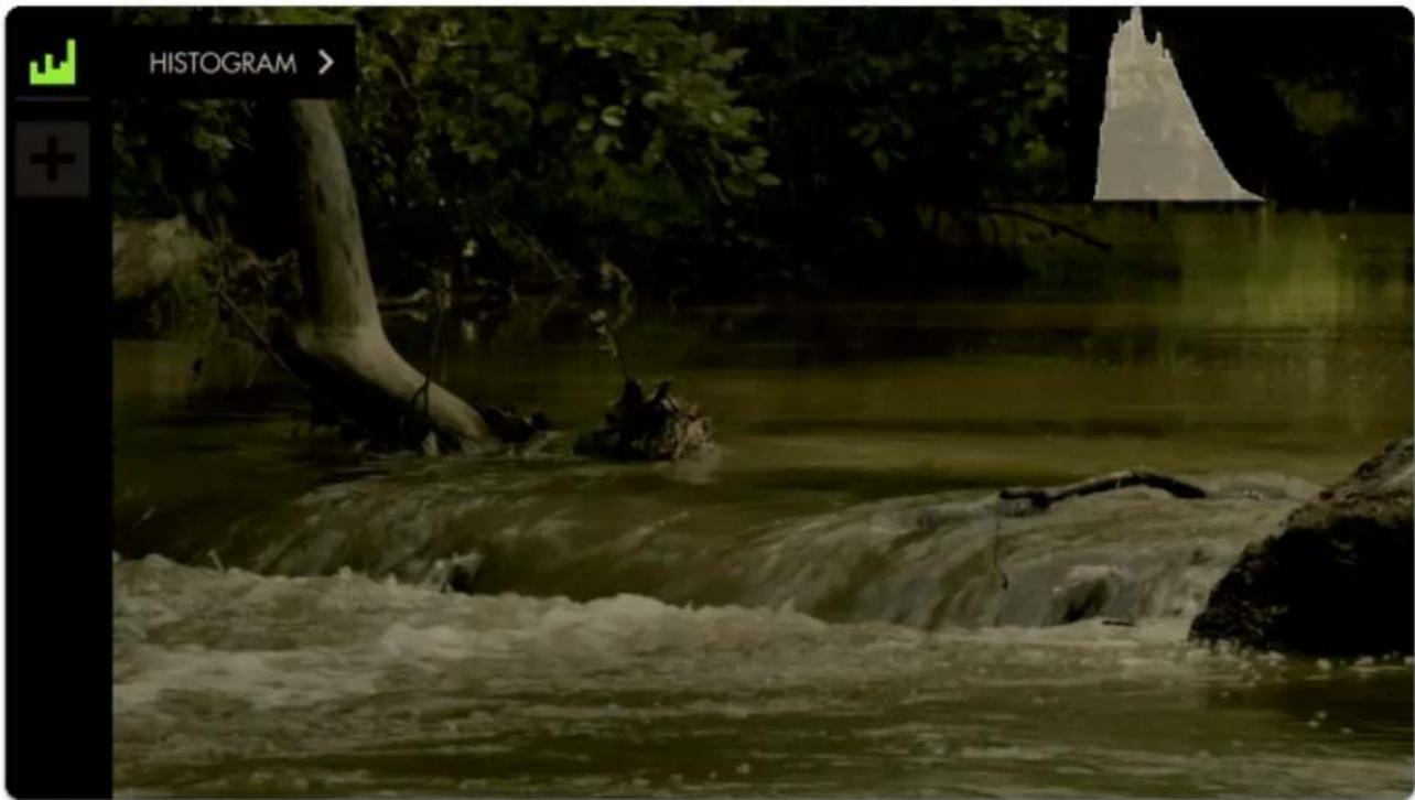
text_image
HISTOGRAM >Since this is a daytime shot with relatively even light (no super-bright objects) we can roll exposure to better balance the 'lump' of the graph toward the center.
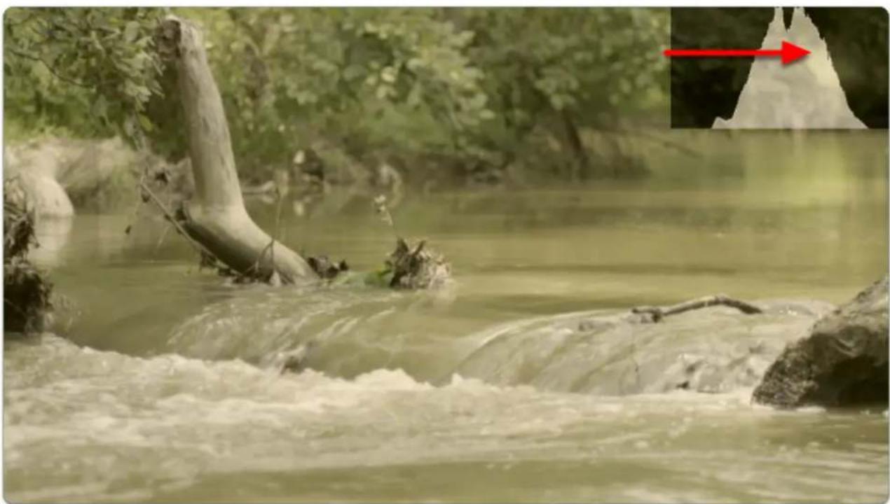
natural_image
Fresh water flowing through a forested stream with tree trunks and rocks, no visible text or symbols
SmallHD User Manual
There are no 'spikes' toward the far-left or far-right of the graph, meaning everything in our shot is within a usable exposure range and as a result no clipping is occurring.
Let's edit how the graph appears by navigating right or tapping the arrow when 'Histogram' is highlighted.
For a bit more useful info you can navigate to 'STYLE' and set from LUMA to RGB to get access to color information in addition to luma/value.
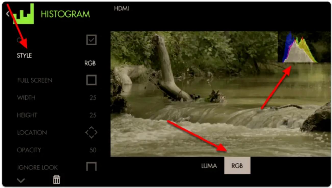
text_image
HISTOGRAM STYLE RGB FULL SCREEN WIDTH 25 HEIGHT 25 LOCATION OPACITY 50 IGNORE LOOK LUMA RGB
Just as with Waveform, using RGB mode lets you see the individual luma values of red, green and blue that make up your image - If you see a distinct separation of colors on the graph you will notice more colorization/saturation.
To adjust the position of the Histogram on the screen (to arrange with other tools or for better general visibility) alter the LOCATION and use the joystick or tap around the screen to place the graph.
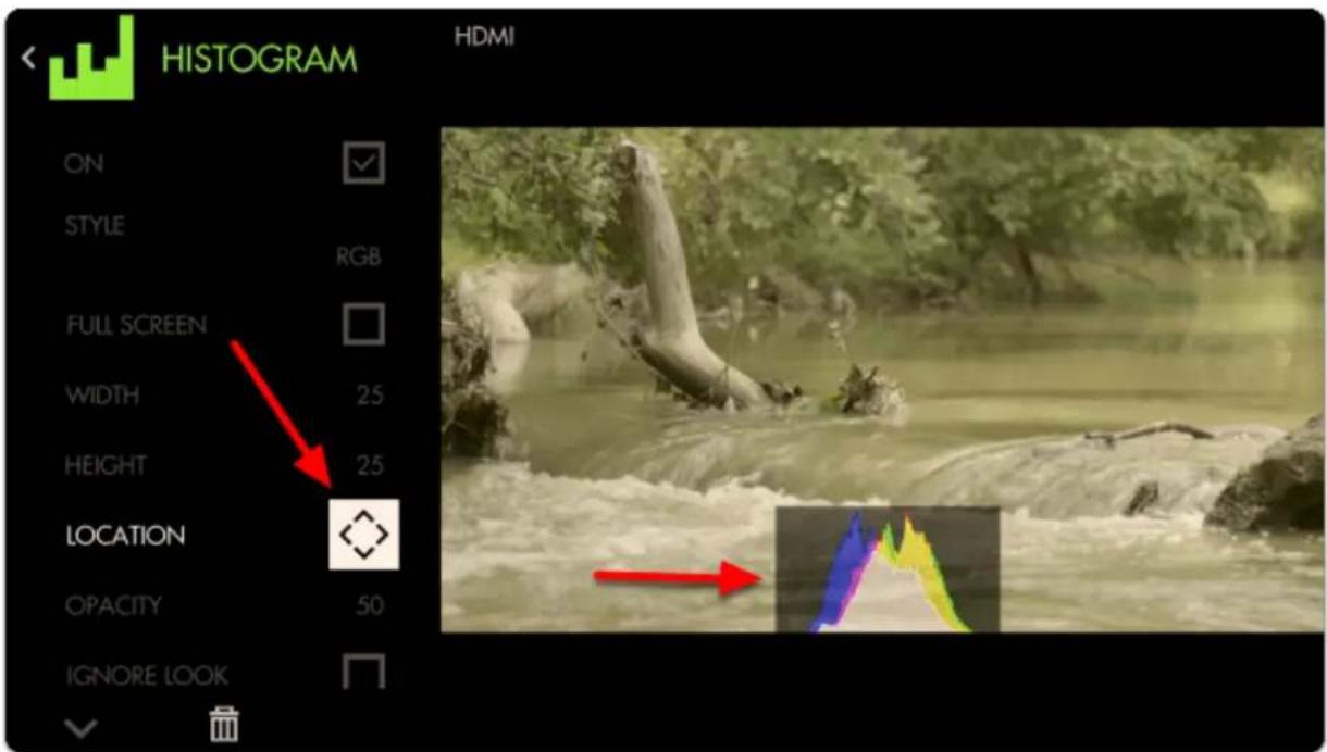
text_image
HISTOGRAM ON STYLE RGB FULL SCREEN WIDTH 25 HEIGHT 25 LOCATION OPACITY 50 IGNORE LOOKWe can also adjust the size of the graph any way we wish (or use FULL SCREEN to dedicate an entire page to the feature)
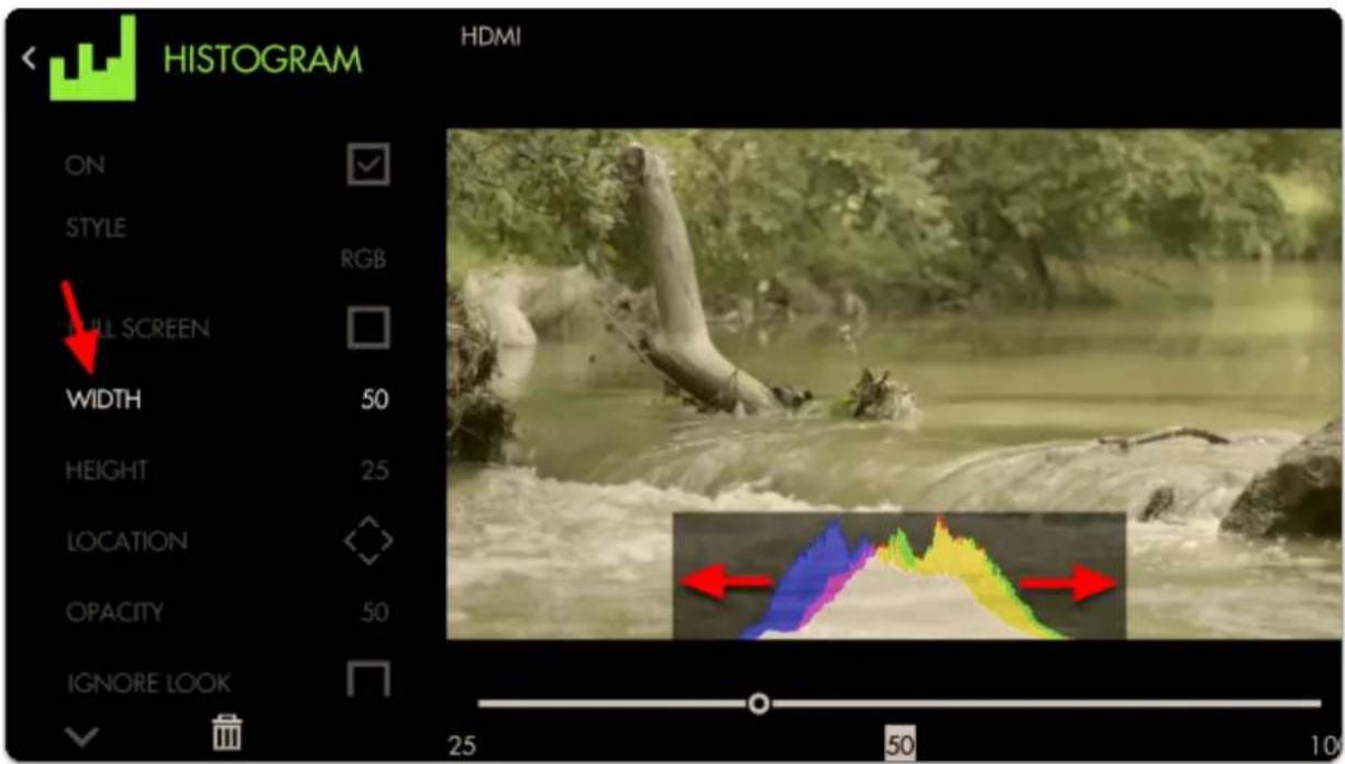
text_image
HISTOGRAM HDMI ON STYLE RGB FULL SCREEN WIDTH 50 HEIGHT 25 LOCATION OPACITY 50 IGNORE LOOK 25 50 10With the addition of RGB data, we can tell that our image has a warm cast toward the brighter end (yellow area) and a cooler cast in the shadows (blue area).

Cameras which have an 'auto exposure' will often use an internal histogram as their guide, meaning it will center the 'weight' on the graph as best as possible just as we are doing here manually.

Because the Histogram does not know the context of your shot it can sometimes be tricky to use for exposure balance. For example a brightly lit snow scene will weigh heavily on the right but if we roll exposure to center the 'lump', the whole scene will then be too dark, because brightly lit snow should appear brightly lit. Conversely if you are shooting a subject under a spotlight but against a dark background, the Histogram may appear as if you have an underexposed image if it's reacting to the dark background. For these cases we recommend the Waveform, Exposure Assist or Zebra as they can report issues from discrete portions of the image.
Waveform

text_image
WAVEFORM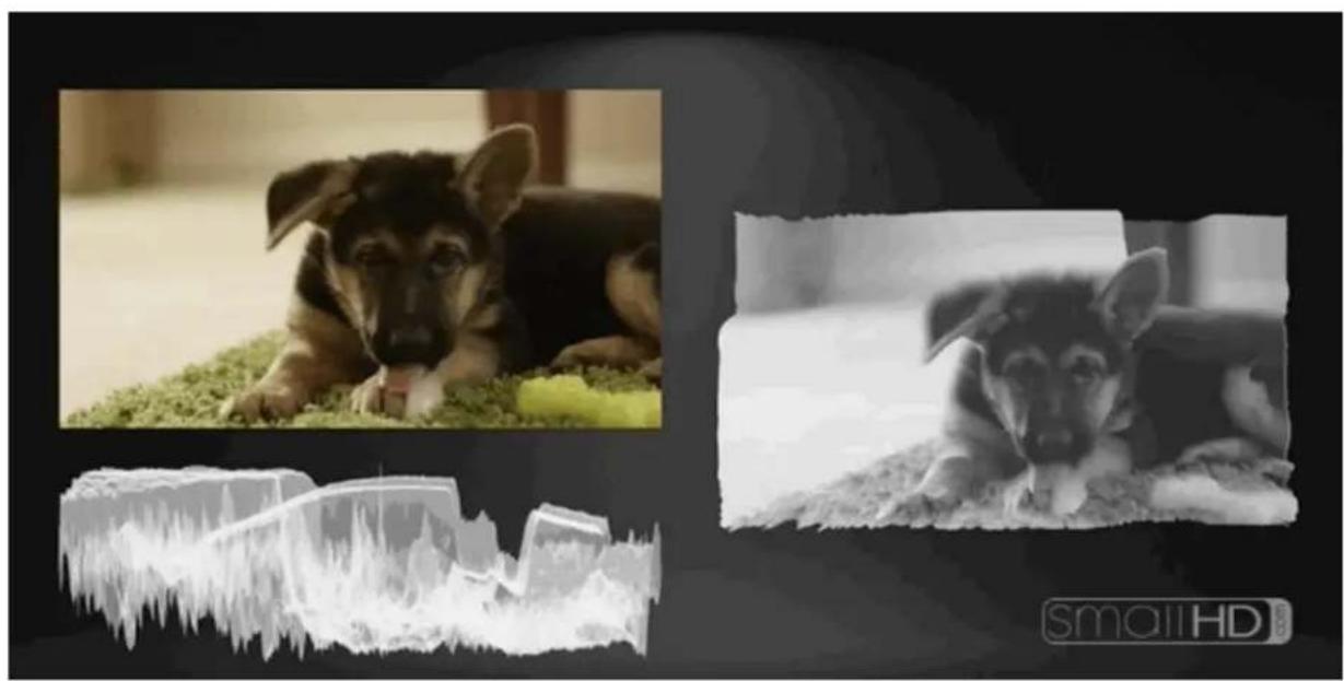
natural_image
Composite image showing a German Shepherd dog resting on grass, a close-up of a German Shepherd dog lying on the ground, and a 3D ice cream strip labeled 'smallHD' (no text or symbols in the main visual elements)The Waveform is generally considered the most robust exposure tool because it plots your image's luminance (brightness) – and chrominance if using RGB mode – to a graph but unlike the Histogram, it physically matches the screen from left-to-right.
1. Waveform - Overview
Although SmallHD provides many available tools to help with setting proper exposure, most of the decision will be down to what works for you. Use this section if you need help deciding where to start.
The Waveform is an extremely comprehensive exposure tool but when needing to understand your exposure levels from a quick glance, Exposure Assist or Zebra may be better options.

SmallHD User Manual
Once you get comfortable with how the Waveform works you can quickly reach optimal exposure with it by balancing exposure between the top and bottom of the graph to make sure highlights and shadows aren't being clipped too harshly. If they are, perhaps adding some light into shadow areas or diffusing/filtering highlights can help compensate.
Waveform is often considered the best exposure tool because it allows very precise measurement of all aspects of the image's luma (brightness) and chroma (color) by setting the 'style' to RGB.

Because the Waveform gains the most benefit when using the full width of the screen (so that it matches the image horizontally) it might consume more of your image than you are comfortable with. It might work best as its own screen or taking up the lower portion (1/3) of the screen, but you can use this tool however it will work best for you.
2. Waveform Settings
Access the Waveform's settings menu by navigating right or pressing the right arrow when the Waveform is highlighted.
On
Toggles the Waveform On/Off. This can also be done on the tool bar by selecting the tool and activating or deactivating it. It will be Green when active and Grey when inactive.
Ignore Look
Allows you to apply a Look (3D LUT) to your footage while monitoring a waveform that is not affected by the Look. This lets you make exposure decisions based on the signal coming from the monitor for ideal flexibility in post-production.

We recommend leaving this on (Ignoring your LUT) for most shooting scenarios so that the waveform applies to the footage being recorded instead of shifting around while adding or adjusting a 3D LUT.
Style
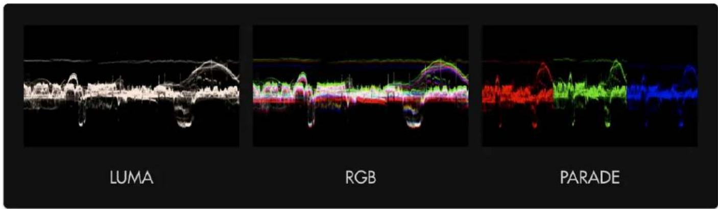
text_image
LUMA RGB PARADEYou will have three options:
LUMA displays a brightness/luma plot only
RGB graphs each primary color on top of one another.
RGB PARADE physically separates the Red, Blue and Green channels into discrete sections from left to right so they can be viewed easily in isolation.
LAYOUT
Layout has a set of Submenus that will allow you to set the positioning, scale and visibility of the Waveform.
\*Full Screen
Displays the waveform in a full-screen view, useful when viewing from a distance or if using multiple monitors where another can be displaying the image itself.
\*Width
Scales the Waveform horizontally.

We recommend leaving this at 100 (or set to the same width as your image) to gain the benefit if the graph matching up evenly with your image from left-to-right.
\*Color
This is only available if using LUMA Style.
You can select the color of the waveform if desired from a specified set.
\*Height
Scales the Waveform vertically.
\*Location
Set the location of the Waveform to a spot of your choosing - useful when placing multiple tools/scopes on screen.
There are 9 positions to choose from:
TOP - Left, Center, Right
MIDDLE - Left, Center, Right
BOTTOM - Left, Center, Right
(Full screen is also an option)
\*Intensity
Adjusts the brightness of the waveform graph (the plotted portion) - increase if the graph appears too faint. This affects the colored part of the graph, not the black background, adjust the Opacity to change that.
\*Opacity
Adjusts the transparency of the black background behind the Waveform. 100 is black, 0 is opaque.

For better visibility, boost Intensity to compensate for a lower Opacity if desired.
SPOT METER
Brings up a small, moveable 'window' you can place on the image that highlights the portion of the Waveform it corresponds to. Useful for getting very specific exposure information from a specific part of the image such as skin tones, hot spots or calibration charts.
This will open a submenu for more settings.
\*Enabled
Toggles visibility of the Spot Meter. This must be enabled to open the sub menu.
\*Width
Adjusts the width of the Spot Meter.
\*Height
Scales the height of the Spot Meter.
\*Spot Location
Set the location of the Spot Meter to an area of your choosing. It follows a 7x7 grid giving you a preset 49 locations.
LEGEND
Places a guide onto the Waveform graph listing numeric IRE (brightness) values for measuring levels.
This will open up a set of submenus.
\*Overlaid
Toggles if the legend is outside of the waveform (right) or over the top of it (left).
*If in full screen mode, the outside will push the legend off the screen. If you want the legend outside and have a full screen waveform, you will need to adjust the size manually rather than using the fill screen and shorten the width 94.
\*Num Labels
This breaks the measurements from 0 to 100 into multiples:
2 - x100 (0,100)
3 - x50 (50,100)
4 - x33 (33,66...)
5 - x24 (25,50...)
6 - x20 (20,40...)
7 - x17 (16,33...)
8 - x14 (14,28...)
9 - x13 (12,25...)
10 - x11 (11,22...)
11 - x10 (10,20...)
\*Legend Color
Change the legend (numbers) color if in need of extra readability of IRE values against your background.
\*Line Color
Change the line color of the graph to more clearly see when your values are reaching a specific level. This will correlate to any numbers on your legend, giving you a horizontal line to use for measurement.
Adjusts the opacity of the graph lines to make them stand out - or invisible to improve graph visibility.
Adjusts the thickness of the graph lines for readability.
Pixel 0-5.
3. Waveform - Quick-Start
Press right on the joystick or tap the right arrow next to 'ADD NEW TOOL' and navigate to Scopes > Waveform and select to add it to the current page.
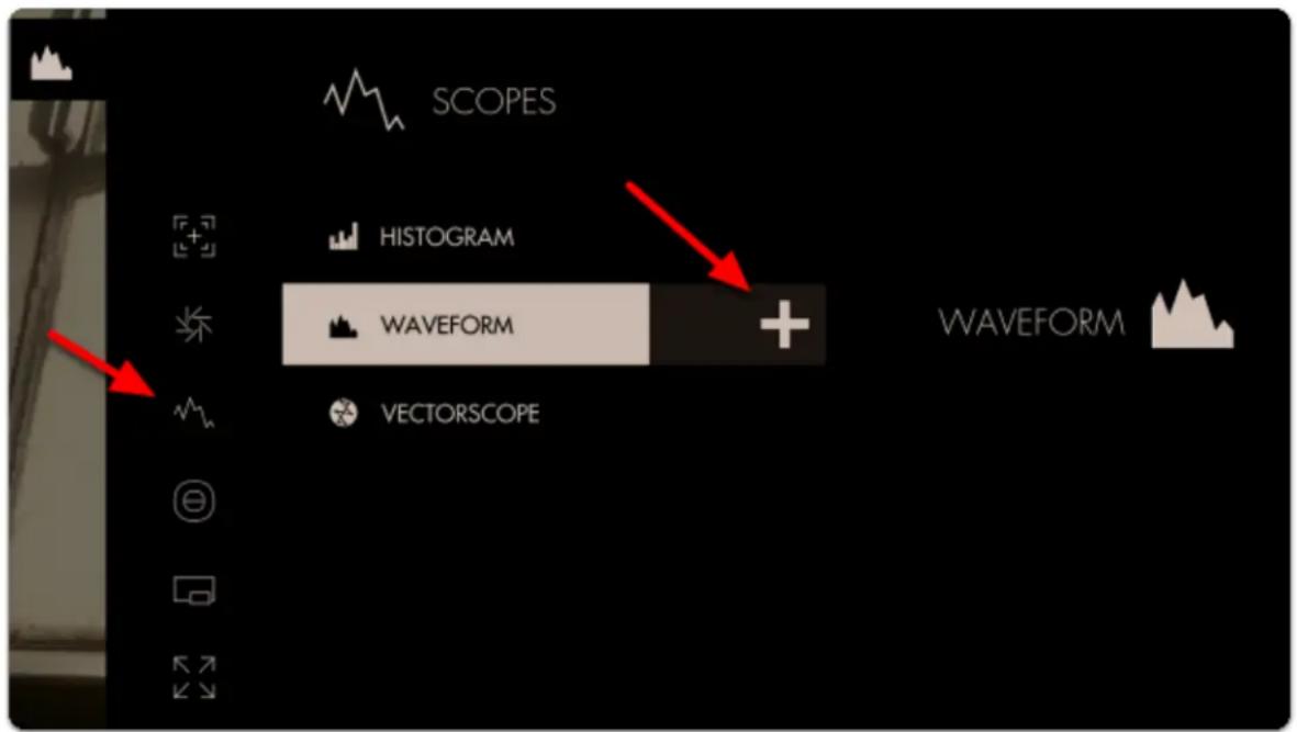
text_image
SCOPES HISTOGRAM WAVEFORM + WAVEFORM VECTORSCOPEOnce added you can edit the settings by navigating right when 'Waveform' is highlighted.
Select 'Style' and switch from LUMA to RGB - this will let you observe each Red, Green and Blue value simultaneously - a unique benefit of the Waveform.
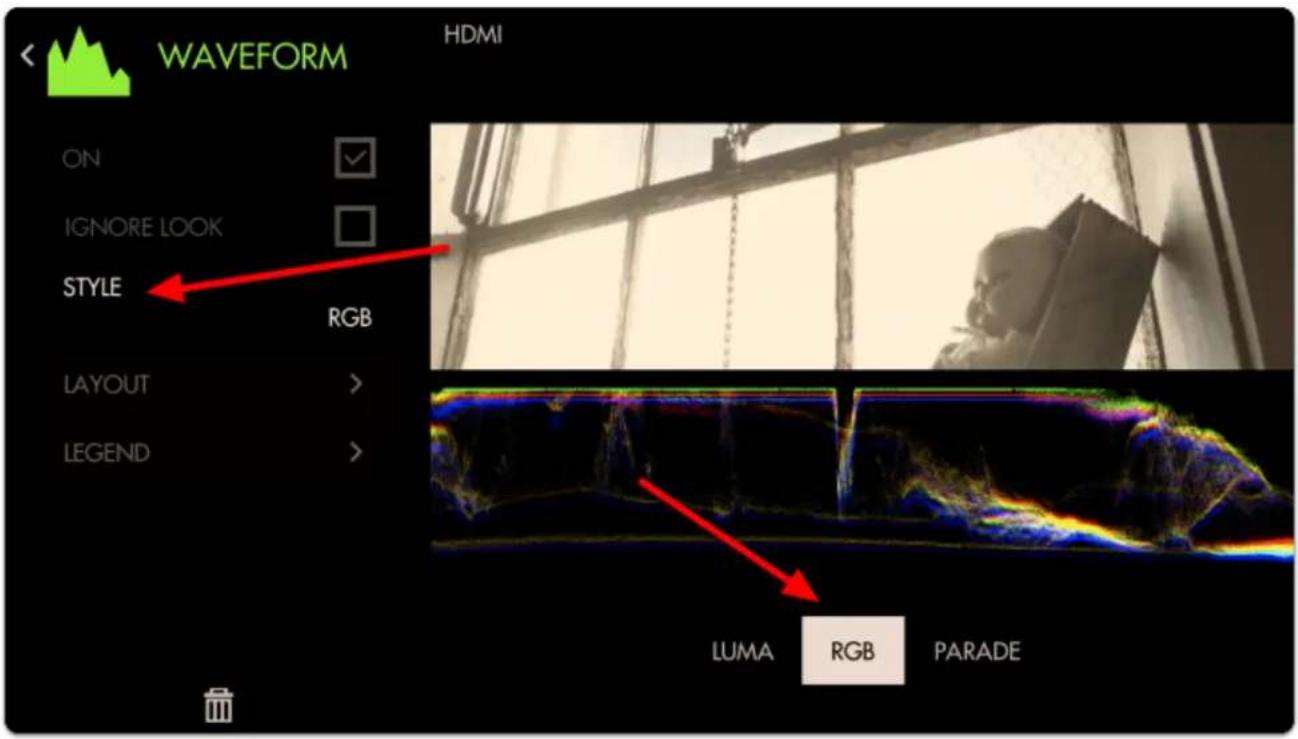
text_image
WAVEFORM HDMI ON IGNORE LOOK STYLE RGB LAYOUT > LEGEND LUMA RGB PARADEBack out of the Edit Tool menu to observe the waveform in action and to accurately expose your footage.
The Waveform 'flattens' at the top when highlights are being blown or 'clipped' - this will result in footage that is a solid 'block' of color without the ability to manipulate it meaningfully in post production.
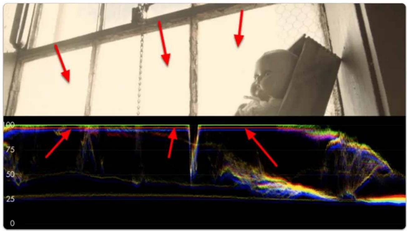
natural_image
Composite image showing a person in a window, red arrows pointing to features, and a 3D thermal or electrocardiogram (likely electrocardiogram) with color gradients from 0 to 100 on the bottom panel.Rolling exposure downwards, the lines 'un-flatten' and much more of the window can now be manipulated in color grading while some areas remain overexposed.
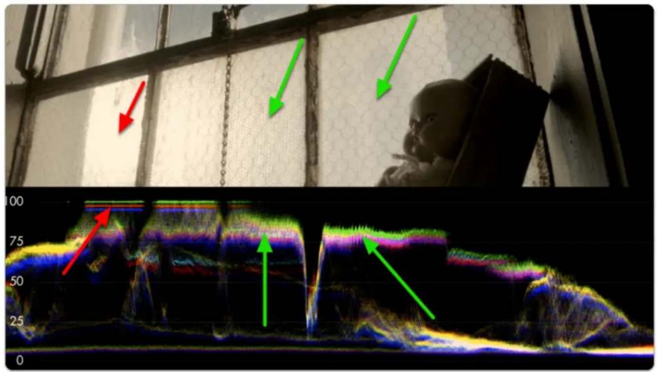
text_image
Medical imaging comparison showing a child near a window with red and green arrows pointing to features, alongside a 3D ultrasound image with color-coded regions.
SmallHD User Manual
If we keep rolling exposure down (closing the aperture) we will continue seeing more 'into' the brighter details at the expense of shadow details which become 'crushed' or 'clipped' and effectively lost similar to overexposure.

The key to finding a healthy exposure relies on a graceful balance between clipped highlights (top of graph) and crushed/noisy shadows (bottom of graph).
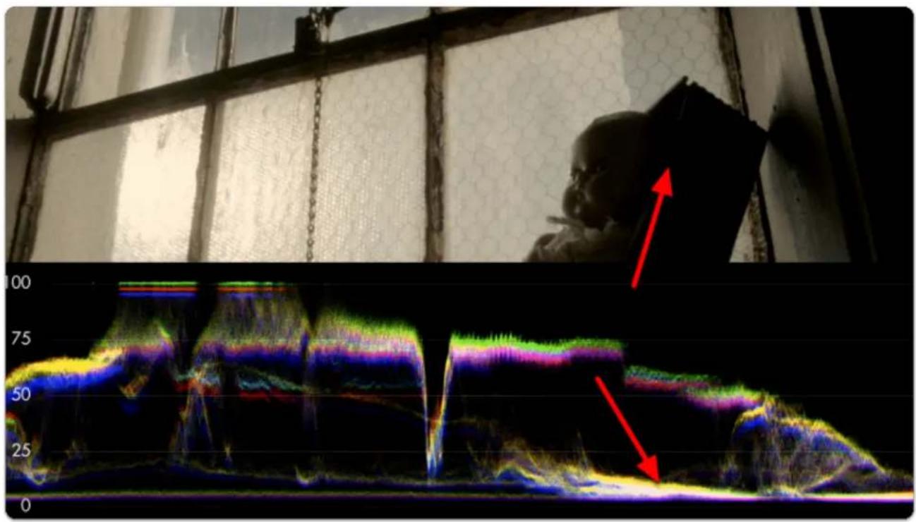
natural_image
Interior view of a room with a person looking up at a window and overlaid with a color-coded ultrasound or electrocardiogram (no text or symbols visible)
The difference between the darkest and the brightest areas that a camera can effectively see detail is known as its dynamic range - this is why high dynamic range is a highly sought after feature among cameras; you are able to capture and therefore manipulate more of your image.
As mentioned before, because we're looking at an RGB Waveform we can can use it to make color decisions in addition to luminance.
If a pure white or pure gray element occupies part of your scene, you can actually white balance with the waveform. Many newer cameras will do this automatically, but it is a good idea to use the spot meter if using a local source.
*Using a Macbeth or Grey card in the field works well.
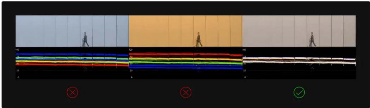
text_image
Diagram showing a multi-level color-coded signal or waveform with labeled axes (100, 25, 50) and marked regions using symbols like red X and green checkmark.Notice how adjusting the white balance setting on the camera shifts the RGB 'bands' - when lined up they turn white, indicating a proper white balance setting.
Vectorscope

text_image
Vectorscope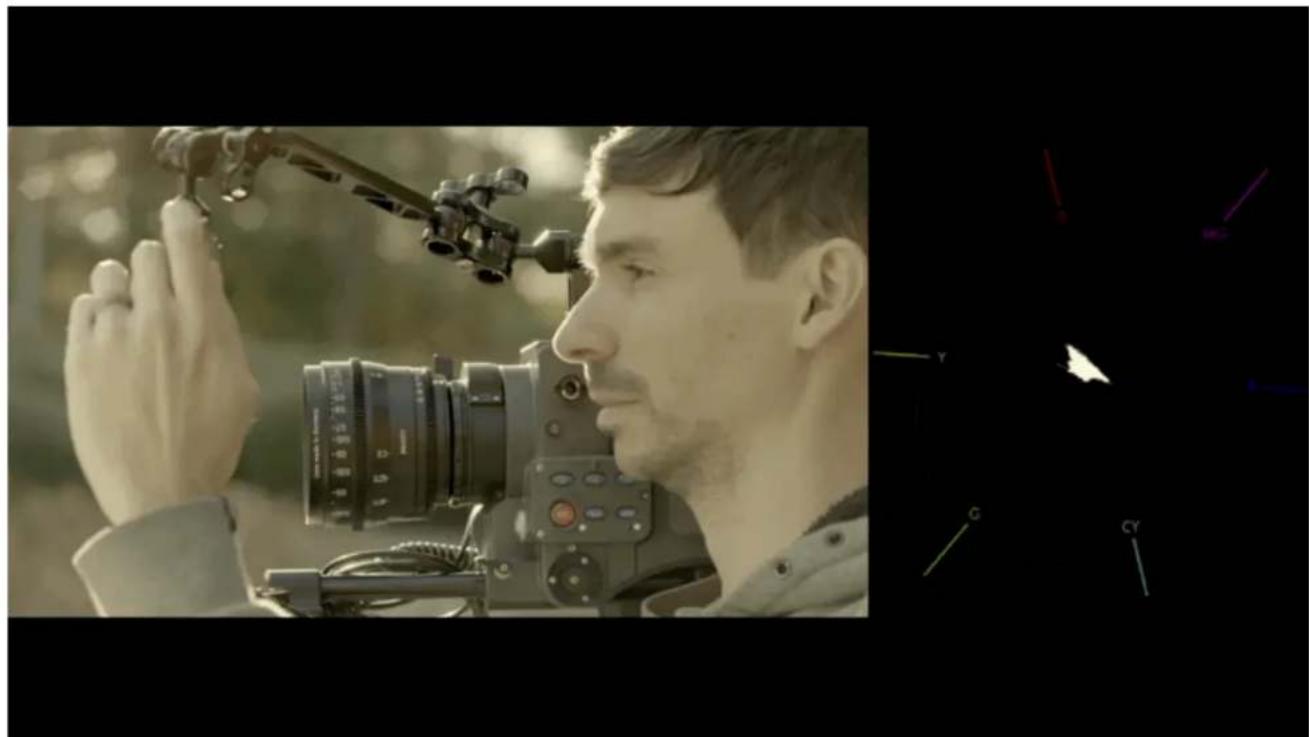
natural_image
Side profile of a person using a camera with a lens, against a blurred natural background (no visible text or symbols)Though generally not considered as 'mission critical' during shooting as exposure scopes such as Waveform & Histogram, the Vectorscope plots the chromaticity, or the hue + saturation of your image onto a color wheel so you can help gauge complimentary color, ensure skin tones are being colorized properly, to visualize how overall scene color is being placed, and where potential adjustments may need to be made in general.
Vectorscopes are also used in Broadcast to make sure that the colors of the footage are exact. Vectorscopes will have a target for each zone. The idea would be if shooting a pure sample (such as a color or macbeth card) that the targets would be hit. You will see vector scopes used in post production to be sure that the colors from shot to shot will match.
Vectorscope - Settings
Access Vectorscope tool settings menu by navigating right or pressing the right arrow when Vectorscope is highlighted in the tool list.
On
Toggles Vectorscope Off/On. This can be done on the Tool Bar by selecting the tool. Active tools are Green, while inactive tools are Grey.
Size
Adjust the size of the Vectorscope for best view-ability.
The size ranges from 20 to 60. At 60, the scope takes up about 2 quadrants of a 3x3 grid.
Location
Arrange the Vectorscope on-screen using various pre-set locations.
There are 9 positions:
TOP - Left, Center, Right
MIDDLE - Left, Center, Right
BOTTOM - Left, Center, Right
Opacity
Set the transparency/opacity of the black background and Vectorscope graticule/graph.
Show Skintone
Displays a skin-tone line/taget directly on the Vectorscope to indicate where to place skin color during lighting to achieve a neutral, natural result.
Vectorscope - Quick Start
In this section we will add a Vectorscope to a page and use it to light a scene with complimentary colors.
'Add New Tool' Navigate to Scopes > Vectorscope and select the '+' to add it to the current page.
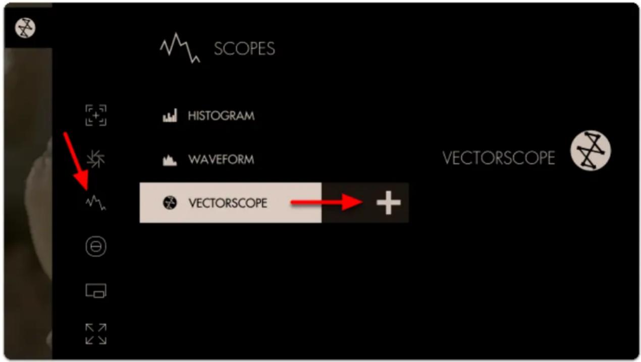
text_image
SCOPES HISTOGRAM WAVEFORM VECTORSCOPE VECTORSCOPEA Vectorscope appears at the bottom of the image. The 'blob' is largely contained in the center of the graticule/crosshairs which means the colors of the current image are not very saturated (which is especially true as this footage is using log-based gamma).
The Vectorscope represents saturation as distance from the center of the circle, and hue as the angle around it.

text_image
Red Magenta Yellow Green Cyan BlueIf we apply a LUT to this page, the Vectorscope reacts by expanding its plotted area. The scope confirms that we are viewing a more heavily saturated image after applying the look.

text_image
no LUT LUT applied
The Vectorscope uses the same layout as a color wheel and therefore principles of color theory apply - for example we can achieve complimentary colors by ensuring our scene plots to the graph on exactly opposing sides. Perhaps the most common example of this is the
famous/infamous 'teal/orange' look popularized in Hollywood where skin is orange and nearly everything else gets colorized as teal.
We can edit some settings by navigating right or tapping the right arrow when 'Vectorscope' is highlighted in the toolbar.
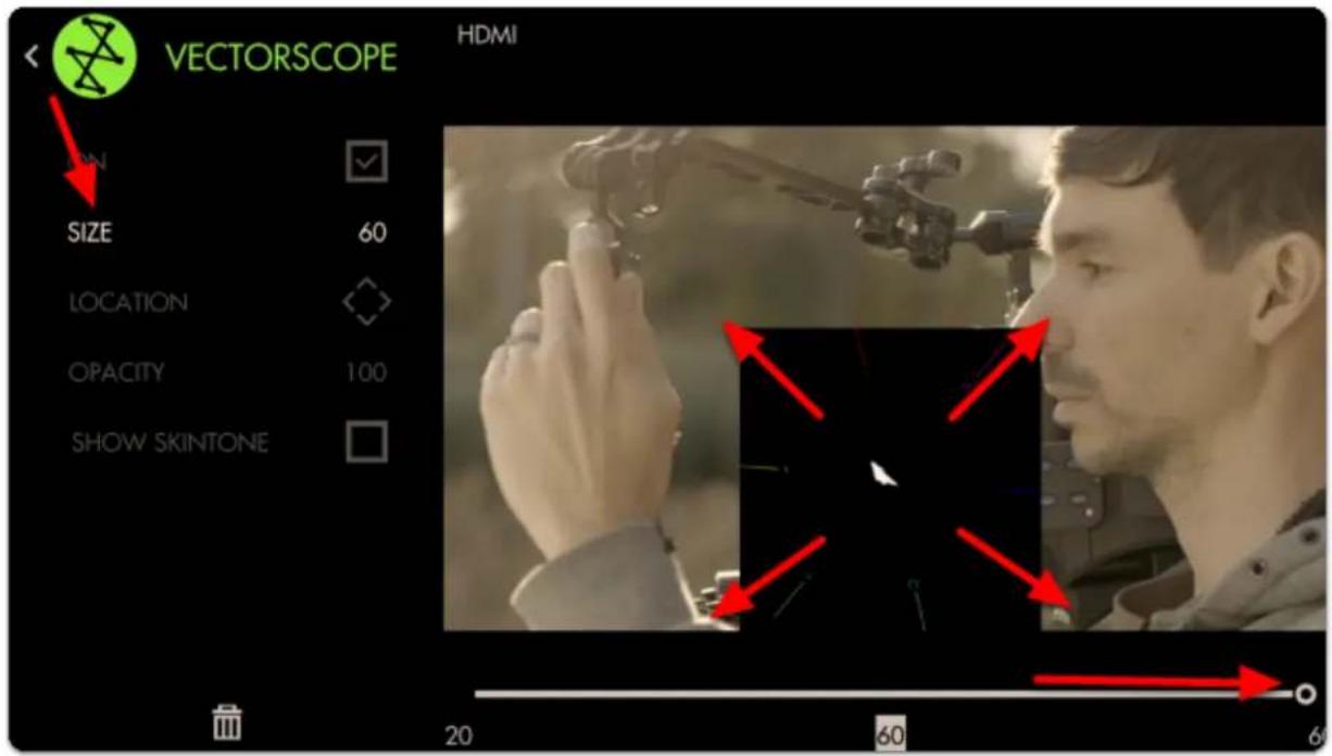
text_image
VECTORSCOPE HDMI ON SIZE 60 LOCATION OPACITY 100 SHOW SKINTONE 20 60 60You can adjust the SIZE of the graph for better visibility. At this stage feel free to use Size & Position or Crop & Scale to arrange the image and scope so that they don't overlap.
Next let's enable SHOW SKINTONE - this provides a line on the graph for where to keep skintone hues for the most natural result under neutral lighting.
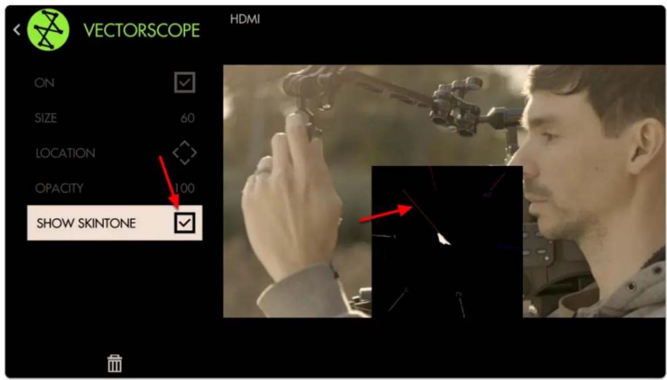
text_image
VECTORSCOPE HDMI ON SIZE 60 LOCATION OPACITY 100 SHOW SKINTONEBecause the entire image is being plotted to the graph all at once, we can check the status of individual areas by using Pixel Zoom in combination with the Vectorscope for spot meter functionality!
Press up on the joystick or pinch-to-zoom on touchscreens while the scope is activated to see its effect.
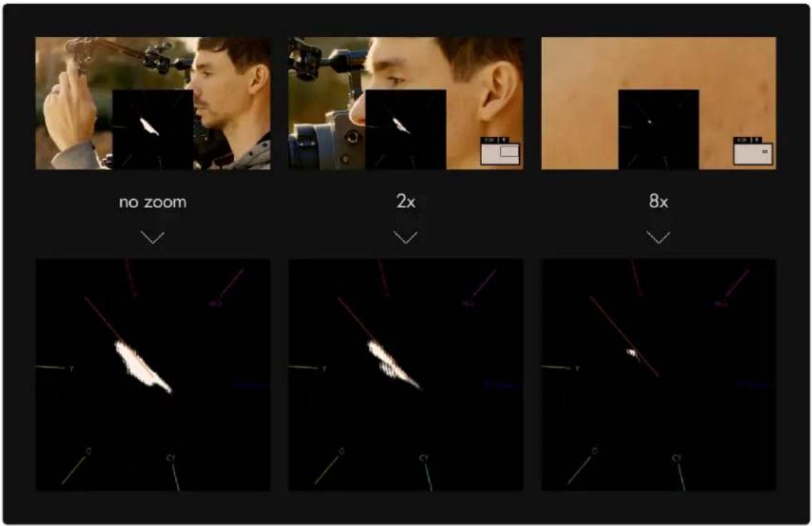
text_image
no zoom 2x 8xZooming into an area consisting of only skin tones reveals the exact hue in which they plot - the result is slightly toward the yellow side - this is the result of a golden reflector which was used to bounce light onto the face. If we had used a silver reflector, the facial tones would rest precisely on the skin tone line.
Tools - Focusing
Focus Assist
Focus Assist
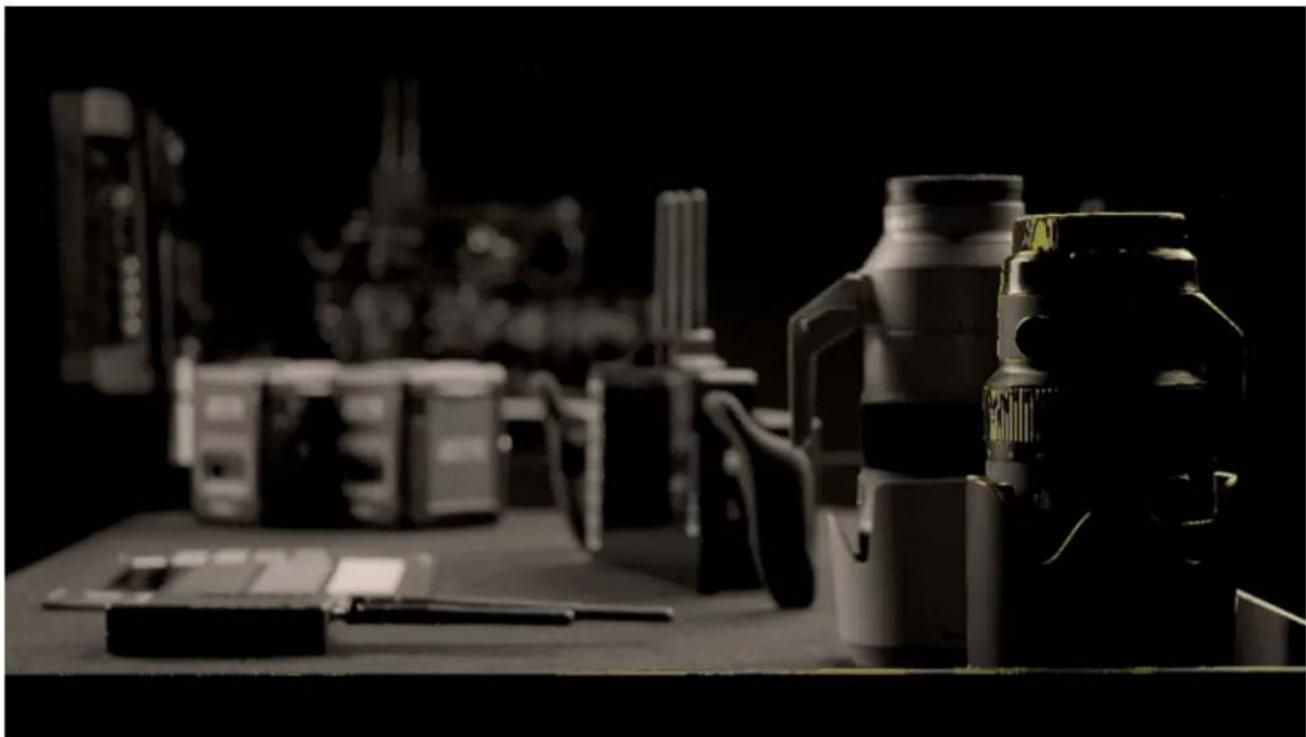
natural_image
Black-and-white photo of various electronic devices including thermos, batteries, and a scanner on a desk (no visible text or symbols)Paints a highlight around in-focus edges, enabling very fast and accurate focusing on-the-fly without needing any additional tools. We have some Tips for focusing here.
Focus Assist - Overview
If configured properly, Focus Assist makes finding your focus point extremely easy- simply roll focus until your subject is displaying bright edge highlights. Focus Assist is a method to find your focus point because of its pronounced effect on in-focus edges.
Focus Assist is versatile and accurate, only at a slight disadvantage to Pixel Zoom in its overall utility since it doesn't allow for as much direct scrutiny of the underlying image, but at the advantage of

SmallHD User Manual
speedy usage. The way it works is that the filter is looking for hard, crisp edges. When it sees crisp lines, it will add digital noise over the top, giving you a visual cue that those areas are in focus.
*FOCUS ASSIST is a tool that can be very useful for critical focus. It is best used when your depth of field is shallow and you want to be sure that your subject falls within the goldilocks zone. Focus Assist will not be very helpful when used in shots where you have a large depth of field. You will be better off to use calculations based on your Stop, distance and lens.
Depending on how it is set up, Focus Assist generally has a pronounced enough effect on the image that it tends to require its own page to not confuse readings with another feature or other aspects of the image. If you wish to, for example be able to focus and expose your image on the same page with minimal overlays, perhaps try a combination of Peaking and Zebra.
Focus Assist - Settings
On
Enable/Disable Focus Assist tool. You can also do this on the tool bar. Select the tool and activate or deactivate it as desired. Green tools are active, they are Grey when inactive.
Color
Choose the edge highlight color of the Focus Assist- this can be useful to modify if the current color isn't visible enough against your footage.
*If this is still an issue after adjusting color, try lowering the Brightness and/or Contrast
Sensitivity
Sensitivity adjusts the intensity of Focus Assist - a low number causes a faint edge highlight, high numbers cause many more edges to be detected.
In essence this will increase how many edges it will highlight.
Peak Threshold (Peak Thresh)
Peak Threshold is like a 'confidence' slider, the higher the Peak Threshold, the more confident Focus Assist needs to be about an area to paint it as 'in-focus'. Increase this setting to taste after increasing Sensitivity for best results.
B&W Background
Makes the underlying image monochrome so that the highlight color is more visible. This can be useful when you have trouble finding a color for the highlight that will not separate from your background.
Brightness
Adjust the brightness, which will affect black levels and luminance. (ie not a flat log signal) source, translating into a clearer view of what is in focus.

Any active exposure tools will respond to changes in brightness and contrast made here unless "Ignore Look" has been applied on each exposure tool - we recommend leaving these settings checked so that you are making exposure judgements off your original unmanipulated footage.
Contrast
Adjust the contrast of the image, affecting gamma levels.
Focus Assist - Quick Start
Focus Assist benefits from being configured for each camera due to differences in noise levels which can affect readings and exhibit false positives.
'Add New Tool'. Navigate to Focus > Focus Assist and select to add it to the current page.
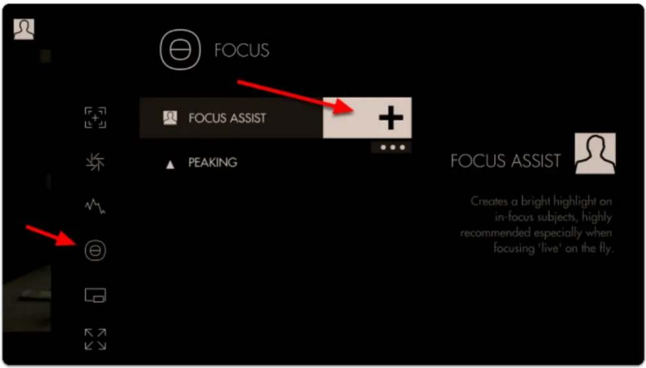
text_image
FOCUS FOCUS ASSIST + ▲ PEAKING FOCUS ASSIST Creates a bright highlight on in-focus subjects, highly recommended especially when focusing 'live' on the fly.Once added you can edit the settings by navigating right or tapping the right arrow when 'Focus Assist' is highlighted.
The default sensitivity is usually a good starting point but if you are not seeing enough edge highlighting, give this value a boost.
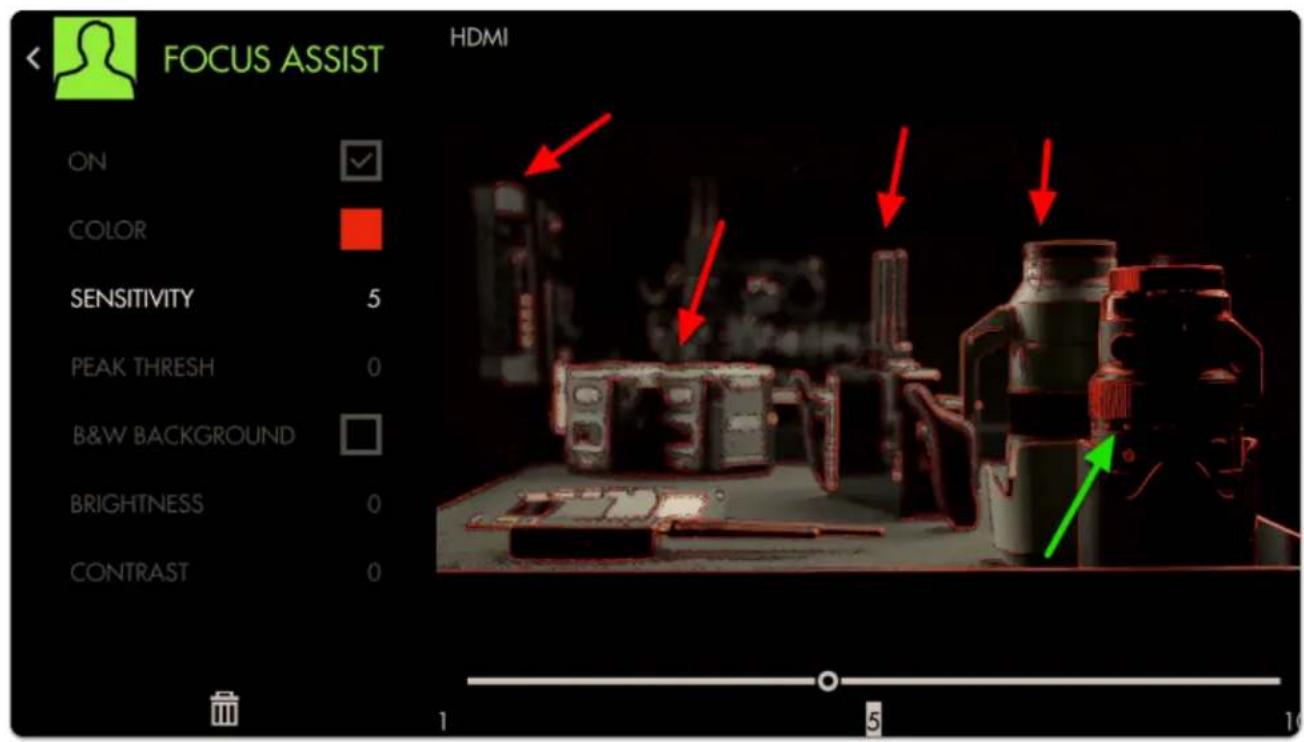
text_image
FOCUS ASSIST HDMI ON COLOR SENSITIVITY 5 PEAK THRESH 0 B&W BACKGROUND BRIGHTNESS 0 CONTRAST 0 1 5 10Notice how we are picking up many edges that are not in focus in addition to the areas that are in focus.
Increase the next slider labeled 'Peak Thresh' to help eliminate the false positives.
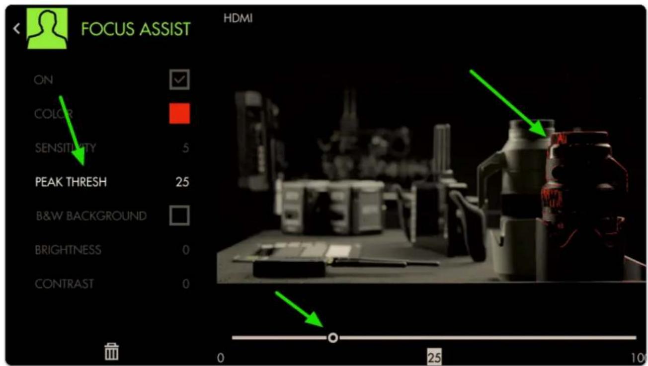
text_image
FOCUS ASSIST HDMI ON COLOR SENSITIVITY 5 PEAK THRESH 25 B&W BACKGROUND BRIGHTNESS 0 CONTRAST 0 0 25 10Now we are getting a much more isolated area of focus with this particular setup.

A good rule-of-thumb for sensitivity/threshold is to adjust until image noise is just out of range of affecting the filter drastically. Some false positives will almost always be present and proper usage is generally about looking at the 'center of mass' of the colorized area as the focus distance.
You can check 'B&W Background' to make the colorizing effect stand out more if view ability is compromised.
Accurately rack focusing on-the-fly is now made vastly less tricky by way of Focus Assist!
Peaking

text_image
PeakingPeaking essentially mimics an exaggerated 'sharpening' filter like you may find on a consumer TV - this effectively increases contrast on in-focus portions of your image while retaining full color unlike Focus Assist. Because of its relatively benign effect on the image this makes it great to use in combination with other features.
Peaking - Overview
Focusing with Peaking is simple- just look at where edges are being highlighted more drastically than others and this gives an indication of where your focus is placed.
Apart from the effect not being as visible as with Focus Assist, getting focus with Peaking can be done very quickly if within a clear enough view of your monitor.
Because Peaking doesn't have an extremely pronounced overall effect, critical applications where you may not have as clear a view of the monitor may benefit when using Pixel Zoom or Focus Assist.
Because it only enhances edges to a certain degree and doesn't otherwise mess with the image, Peaking is very useful in combination with other tools and scopes.
Peaking - Settings
On
Enables/disables the Peaking tool. You can also enable or disable the tool by selecting it on the tool bar. It will be Green when enabled and Grey when disabled.
Intensity
Adjust the opacity of the edge highlighting effect - increase for a more visible 'halo' with which to focus.
Brightness/Contrast
Adjust the brightness/contrast of the image to feed the Peaking filter with an adequate (ie not a flat log signal) source, translating into a clearer view of what is in focus.

Any active exposure tools will respond to changes in brightness and contrast made here unless "Ignore Look" has been applied on each exposure tool - we recommend leaving these checked so that you are making exposure judgements off your original footage.
Peaking - Quick Start
The main benefit of using Peaking to focus your shot is that due to its relatively low impact on the image, we can use multiple tools along with it on a single page. in this example we'll add Peaking to a page that already has Frame Guides, a Look (3D LUT) file and the Zebra tool applied.
From any page, click the joystick or tap the screen to bring up 'Add New Tool' and navigate to Focus > Peaking and select to add it to the current page.
Once added you can edit the settings by navigating right when 'Peaking' is highlighted.
To make the effect more visible on footage, increase the intensity slider.
Press the Back button to get to a full screen view of your footage.
You can look at the white 'haloing' appearing around in-focus edges to determine where your focus plane is. Pointing the camera at the ground, you can very clearly what area is in focus.

For tricky shots where you need to focus on a subject as they move toward or away from the camera, try using the ground as a reference point before shooting to get a feel for moving the lens, how far/how fast to turn etc.
If you want a similar but more pronounced effect with which to focus your shot, try Focus Assist
Tools - Overlay
Look (3D LUT)

text_image
LookA Look or 3D LUT is a simple but very powerful way to apply a color grade to footage. 3D LUT files are quite small, (often around 1MB) and can be produced with most any color grading software and can be saved on to an SD card for use on the monitor or at any point in post production.

3D LUTs are particularly powerful when used with SmallHD monitors - many can be applied simultaneously on several pages so visualizing color variants on set is made as easy as swiping from page to page. We have some sample LUTS that you can
Look - Settings
Access Look tool settings menu by navigating right/pressing the right arrow when Look is highlighted in the tool list.
On
Toggles the Look Off/On. You can also do this on the tool bar. Select the tool and activate or deactivate it as desired. Green tools are active, they are Grey when inactive.
Look File
This will list the LUT file associated with this too. To add a LUT, Select this option and it will open a browser for your SD card. There should be some default Internal LUTS that we have provided as a base, but we always recommend that you use one that is ade for your production by either your DIT or Editor to give the closest results to Final.

SmallHD User Manual
*Many camera manufactures will post LUTS for corrections for their specific camera models on their websites. This is a god place to go to get a base LUT.
*REMEMBER this is an approximation to show what the footage will remember when finalized. Since there has been no post processing (color enhancements etc) this will not be the Final result but rather a representation.
Intensity
This setting lets you scale back the effect of the Look for situations where color & value are being pushed too far. Leave this at 100% if you wish to maintain accuracy of the LUT, this will in effect, change the "overlay opacity" like in photoshop.
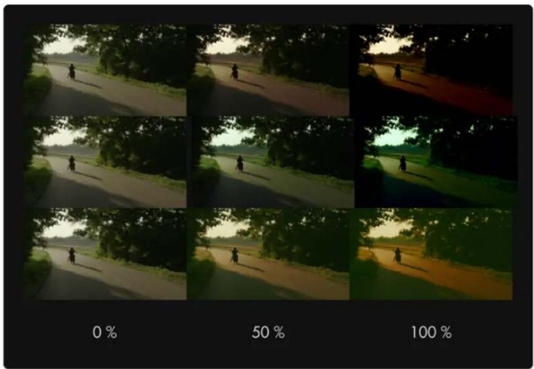
text_image
0 % 50 % 100 %
For LUTs with a high default intensity, this is a great option to be able to visualize a 'toned down' version - just apply the same LUT with the same intensity in your color grading application to match the look on set!
Input Data Range
If your LUT has been designed for 'legal' broadcast range (16-235 for 8-bit, 64-940 for 10-bit), use this setting so that your signal gets displayed properly. If you aren't sure what this means, leave at the 'full' setting. Full should give you the spectrum set in the LUT itself. This will be most noticeable when using scopes.
Output Data Range
This setting currently mirrors the selection of 'Input Data Range' - splitting input/output data ranges is on the roadmap for a future firmware update.
Converting a LUT using Davinci Resolve
If you need help creating a LUT or are having issue loading one, we have a tutorial that can help. We also have a more detailed walkthrough of the using the LUT process that you may also find helpful.
Look (3D LUT) - Quick Start
In this section we'll place a downloaded look on an SD card and apply it to a page.
Using a computer, place as many Look files as you wish onto an SD card. For this example we'll be using our very own "Movie Looks" pack that you can download here for free.
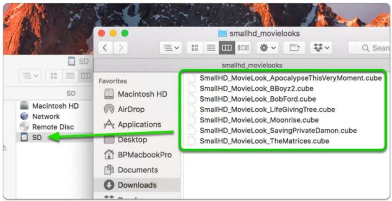
text_image
smallhd_movielooks sd Macintosh HD Network Remote Disc SD Favorites Macintosh HD AirDrop Applications Desktop BPMacbookPro Documents Downloads SmallHD_MovieLook_ApocalypseThisVeryMoment.cube SmallHD_MovieLook_BBoyz2.cube SmallHD_MovieLook_BobFord.cube SmallHD_MovieLook_LifeGivingTree.cube SmallHD_MovieLook_Moonrise.cube SmallHD_MovieLook_SavingPrivateDamon.cube SmallHD_MovieLook_TheMatrices.cubeWith the LUTs placed on the SD card, insert it into your monitor. From any page with a video feed, click the joystick or tap the screen to bring up 'Add New Tool' and navigate to Overlay > Look.
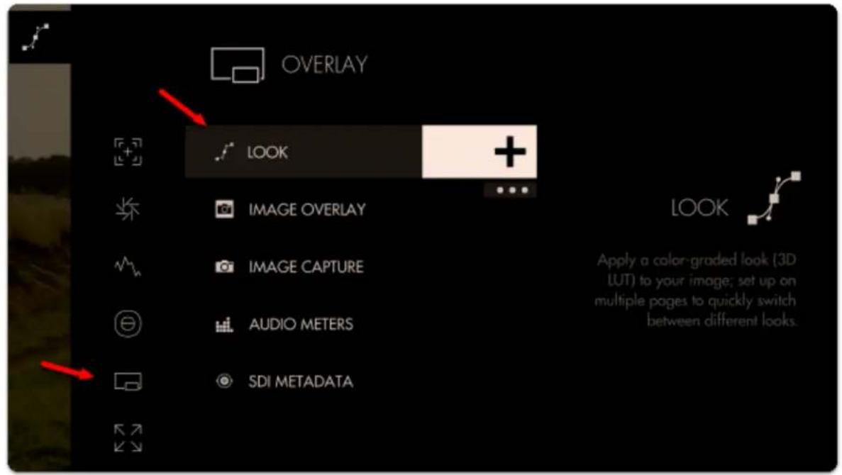
text_image
OVERLAY LOOK IMAGE OVERLAY IMAGE CAPTURE AUDIO METERS SDI METADATA APPY Apply a color-graded look (3D LUT) to your image; set up on multiple pages to quickly switch between different looks.You will then be presented with a file browser where you can select your Look. You can see a preview before making a selection.
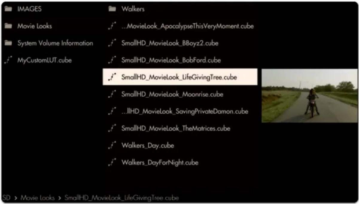
text_image
IMAGES Movie Looks System Volume Information MyCustomLUT.cube Walkers ...MovieLook_ApocalypseThisVeryMoment.cube SmallHD_MovieLook_BBoyz2.cube SmallHD_MovieLook_BobFord.cube SmallHD_MovieLook_LifeGivingTree.cube SmallHD_MovieLook_Moonrise.cube ...IIHD_MovieLook_SavingPrivateDamon.cube SmallHD_MovieLook_TheMatrices.cube Walkers_Day.cube Walkers_DayForNight.cube SD > Movie Looks > SmallHD_MovieLook_LifeGivingTree cubeThe Look is now applied to the page. To get the most benefit out of this feature, try applying different Looks to several pages to switch between them at any point to help inform your decisions about how to approach any given shot!
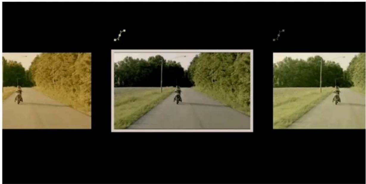
natural_image
Three-panel image showing a motorcyclist riding on a rural road surrounded by trees and grass, with no visible text or symbols.Image Overlay

text_image
Image Overlay
natural_image
Pixel art character with red shirt standing next to a small white object on a white surface against an orange background (no text or symbols)Image Overlay places an image (taken with the Image Capture function or manually placed from a computer onto the SD card) directly on top of your footage - very useful for judging shot continuity, particularly when using the built-in 'blink' feature.
Image Overlay - Settings
Access Image Overlay tool settings menu by navigating right or pressing the right arrow when Image Overlay is highlighted in the tool list.
On
Toggles display of the currently selected Image Capture. You can also do this on the tool bar. Select the tool and activate or deactivate it as desired. Green tools are active, they are Grey when inactive.
Opacity
Set the transparency/opacity of the Image Overlay.
Blink Speed
Blinks the overlaid image at a speed of your choosing. Leaving this at zero disables the Blink functionality. Speed of 1 = on for 2 seconds, off for 2 seconds. Speed of 10 = on and off 2x per second.
Use Latest Capture
Displays the latest Image Capture automatically, even as a new one is taken.
Turning off this option will open the Choose Image option.
Navigate to the image you wish to use, select and confirm and the image name will appear on the tool panel.
Image Overlay - Quick Start
In this section we will add an Image Overlay to a page to help us shot-match.

Having already used the Image Capture function to take a snapshot of our scene, we can now use Image Overlay to display that snapshot back on top of our footage.
From any page with a feed, click the joystick or tap the screen to bring up 'Add New Tool'
Navigate to Overlay > Image Overlay and click on the '+' to add it to the current page.
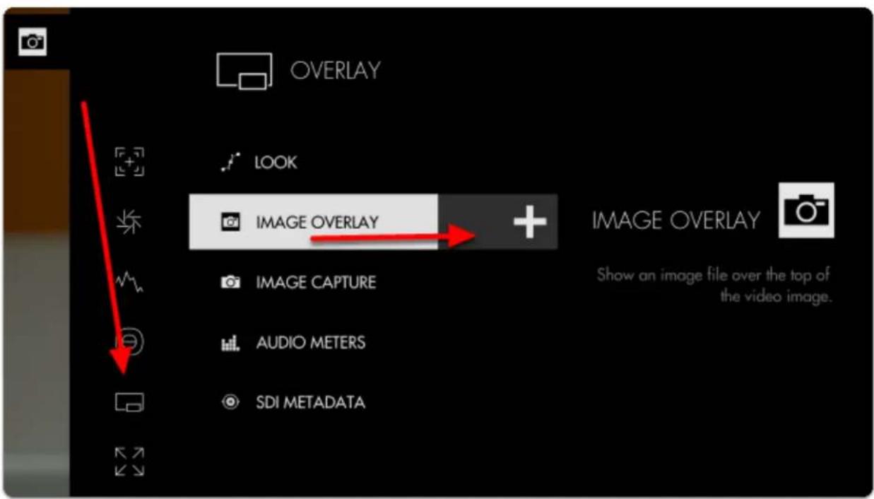
text_image
OVERLAY LOOK IMAGE OVERLAY IMAGE OVERLAY Show an image file over the top of the video image. IMAGE CAPTURE AUDIO METERS SDI METADATABy default Image Overlay displays the latest snapshot taken with Image Capture at 50% opacity.
You can edit the settings by navigating right with a joystick or tapping the right arrow on a touchscreen when 'Image Overlay' is highlighted.
If you wish to overlay a different image, disable 'USE LATEST CAPTURE' and select 'CHOOSE IMAGE'
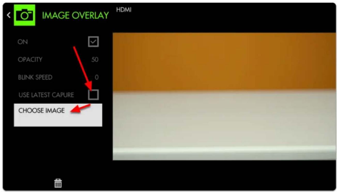
text_image
IMAGE OVERLAY HDMI ON OPACITY 50 BLINK SPEED 0 USE LATEST CAPURE CHOOSE IMAGE
If you wish to overlay an image from a computer, first ensure it is in .jpg format and save it anywhere to the SD card. You can select it with CHOOSE IMAGE [above]
If we then dial up BLINK SPEED the monitor will flash alternately between the live feed and the Image Capture, offering a very clear view of how to fix the shot.
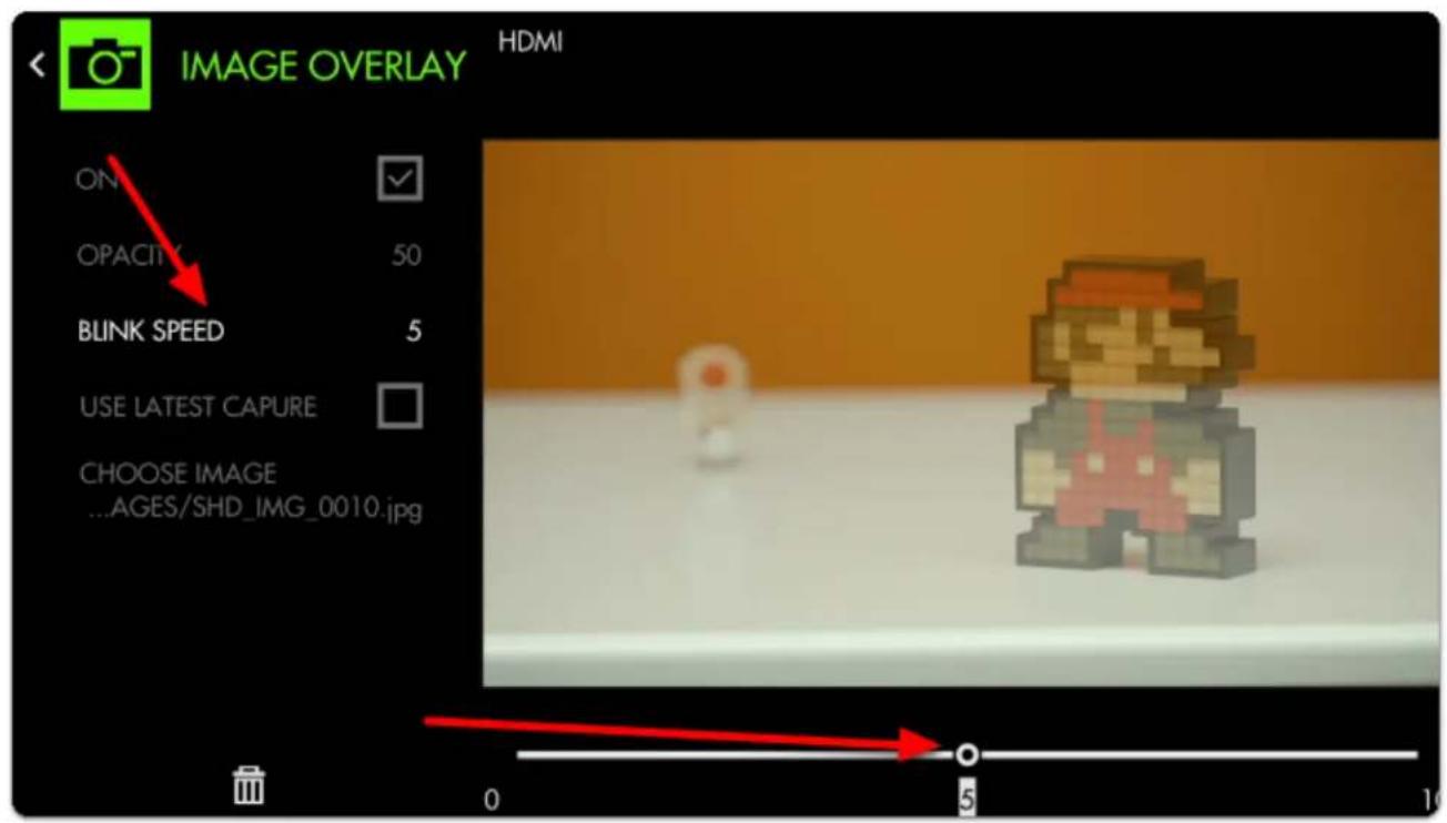
text_image
IMAGE OVERLAY HDMI ON OPACITY 50 BLINK SPEED 5 USE LATEST CAPURE CHOOSE IMAGE ...AGES/SHD_IMG_0010.jpg 0 5 10Increasing the OPACITY gives us a clearer distinction between the two images when blinking (if not set to blink, this will make the overlaid image completely opaque, covering the underlying feed)
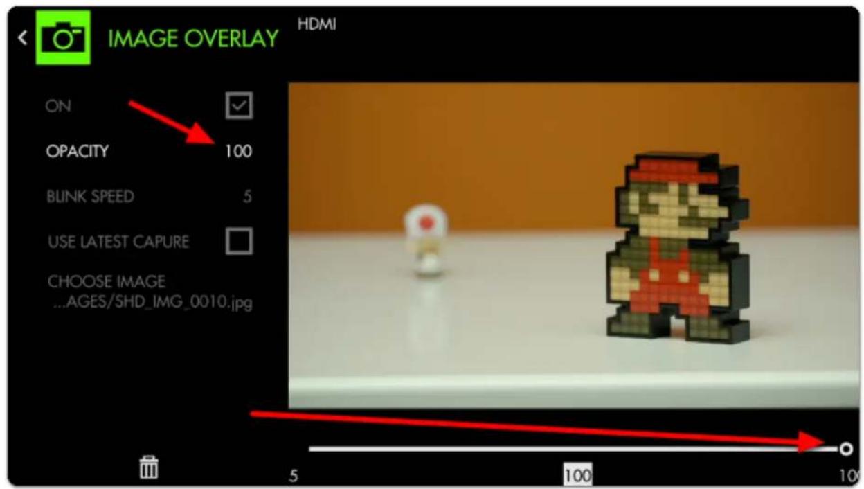
text_image
IMAGE OVERLAY HDMI ON OPACITY 100 BLINK SPEED 5 USE LATEST CAPURE CHOOSE IMAGE ...AGES/SHD_IMG_0010.jpg
SmallHD User Manual
With Image Overlay blinking, we now have a straightforward means of matching the original placement of characters on screen!
natural_image
Pixel art character with red cape and green body, standing on a white surface against an orange background (no text or symbols)Image Capture

text_image
Image Capture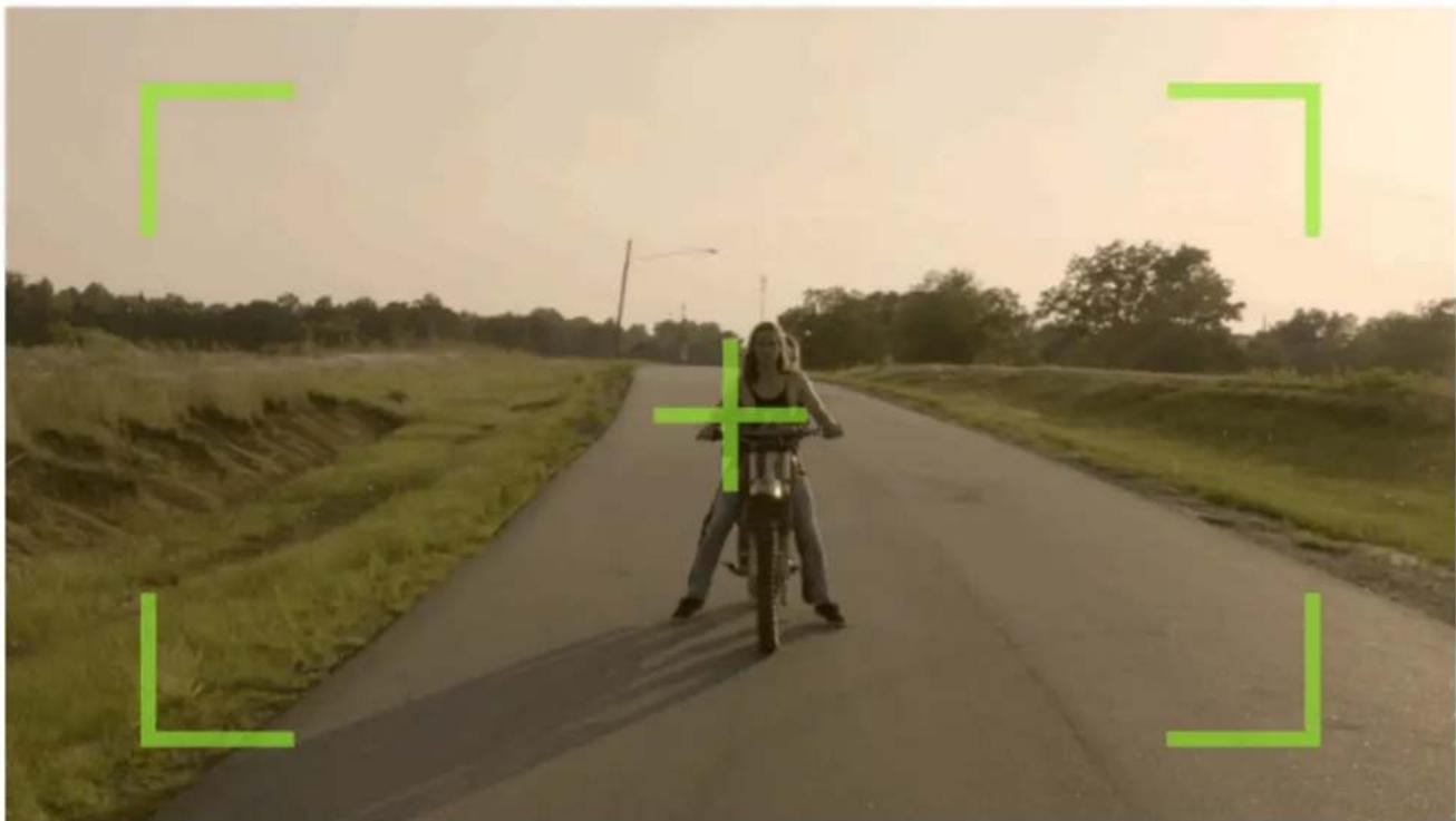
natural_image
A woman riding a motorcycle on a rural road with green landscape background (no text or symbols visible)Image Capture takes a snapshot of the video feed being sent through SDI or HDMI (combined with a LUT if desired) and saves it to an SD card - great for shot matching (continuity) or a quick overview of the days' shots.

If using a 500/700 (joystick) series monitor, the snapshot function can be quickly accessed by pressing the 'O' (capture) button on the top-right of the unit. On Production monitors press the 'CAP' button next to the joystick. Touchscreen monitors will need to tap to activate the tool bar and tap the tool icon to take an image.
*The BT-1 remote can be used with its capture button for any paired monitor.
Image Capture - Settings

Image Capture Settings can be found in the global Settings Menu > Capture > Image Capture
Image Capture - Quick Start
In this section we will add Image Capture to a page and set it up so that a snapshot (with a LUT) gets taken every time we press record on our camera (currently compatible with SDI cameras only) resulting in graded stills of each take from the day's footage.
First insert an SD card on which to save your images.
*You can set a folder structure on your computer and select the destination is the settings menu.
From any page with a feed, click the joystick or tap the screen to bring up 'Add New Tool'.
Navigate to Overlay > Image Capture and select the '+' to add it to the current page.
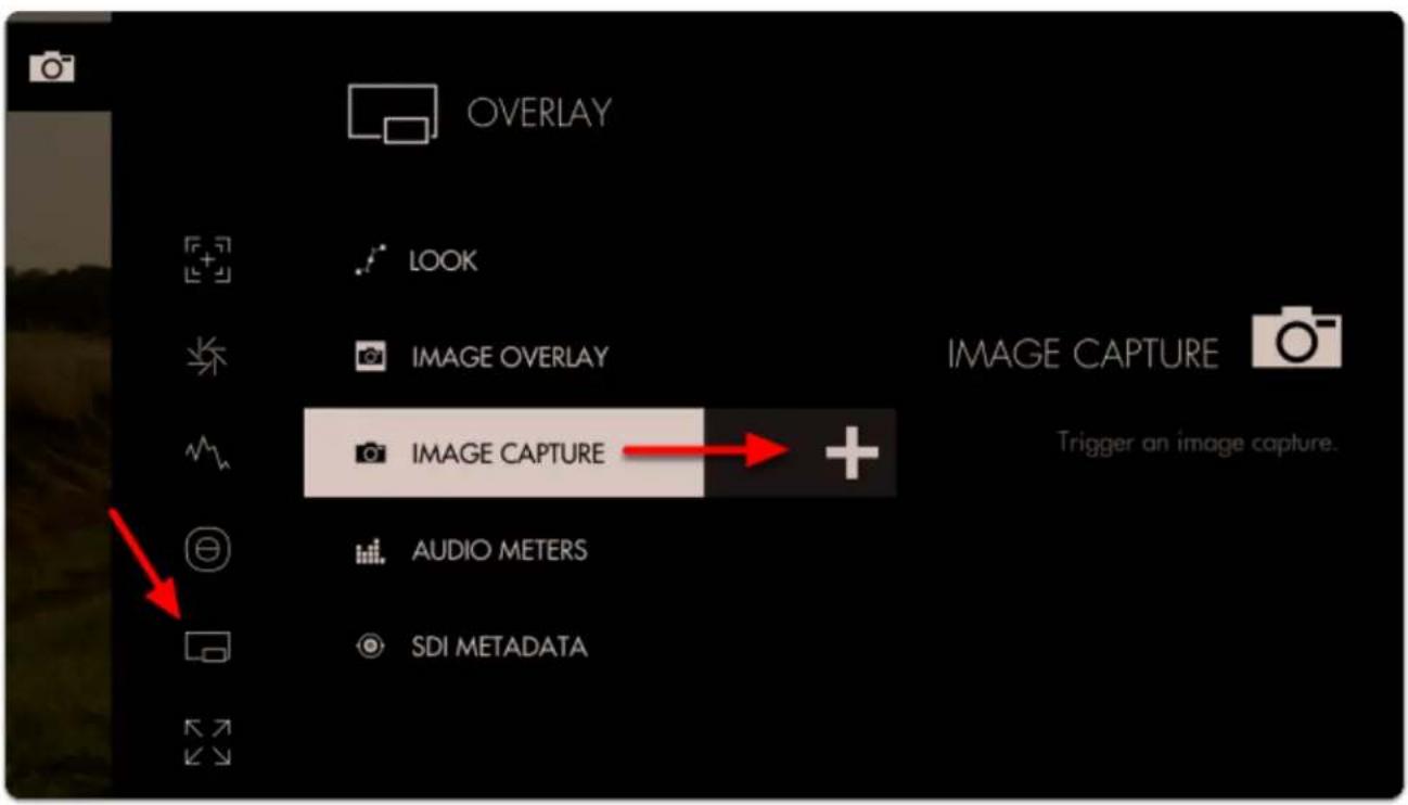
text_image
OVERLAY LOOK IMAGE OVERLAY IMAGE CAPTURE Trigger an image capture. IMAGE CAPTURE AUDIO METERS SDI METADATAYou will see the snapshot overlay appear indicating the monitor is ready for a snapshot.
*This is just letting you know the tool is active, it does not get captured to the image. It does not apply to the capture zone. The Capture will be of the entire frame.
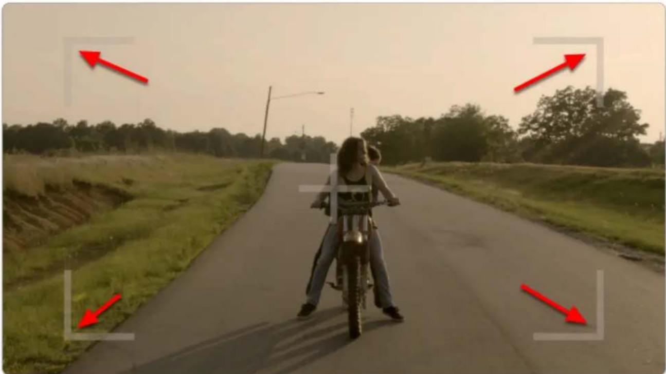
natural_image
Person riding a motorcycle on a rural road with red arrows pointing to the lane (no text or symbols visible)Click the joystick (or tap the touchscreen) to capture an image.
A flag appears at the top to inform you of where you are saving your image and its name.
Next let's enable the capture of LUTs so that we can take color-graded snapshots.
Start by pressing down on the joystick or swiping down on a touchscreen monitor to access the zoomed-out view.
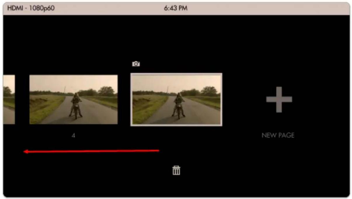
text_image
HDMI - 1080p60 6:43 PM 4 + NEW PAGEMove left until you reach the global Settings menu.
Image Capture settings are located in the far-left Settings menu since they affect the way images are captured globally across the monitor.
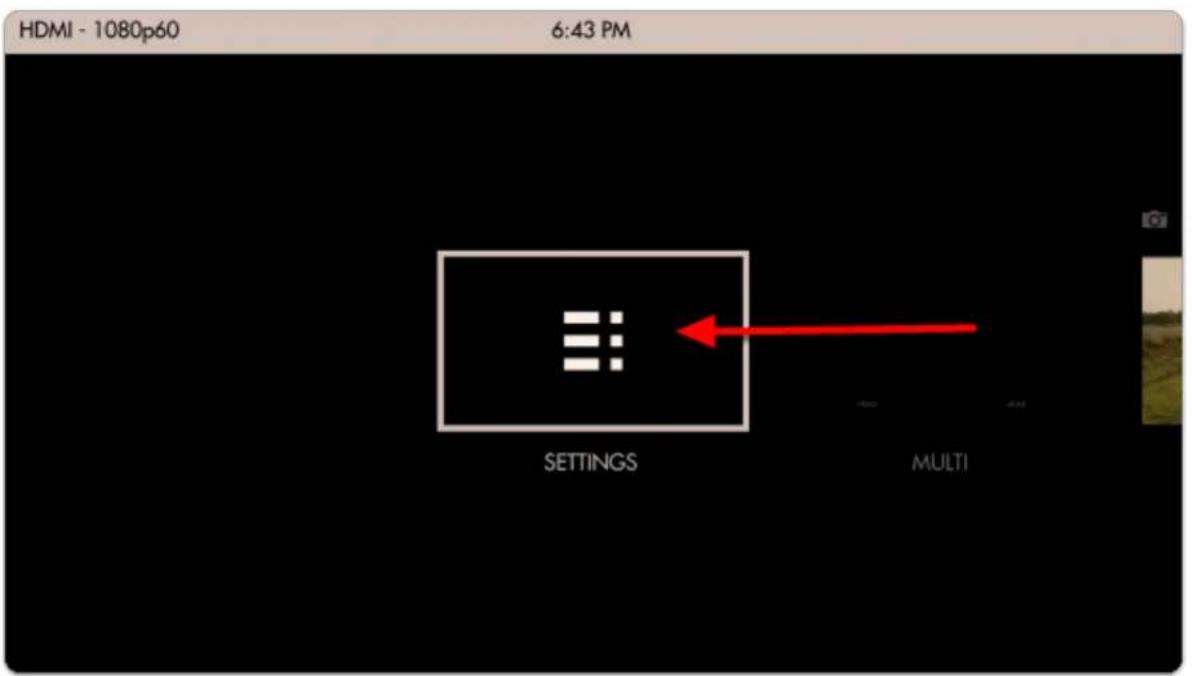
text_image
HDMI - 1080p60 6:43 PM SETTINGS MULTINavigate to Capture > Image Capture and select 'CAPTURE LUTS' to automatically apply any active Look/3D LUT to the saved image.
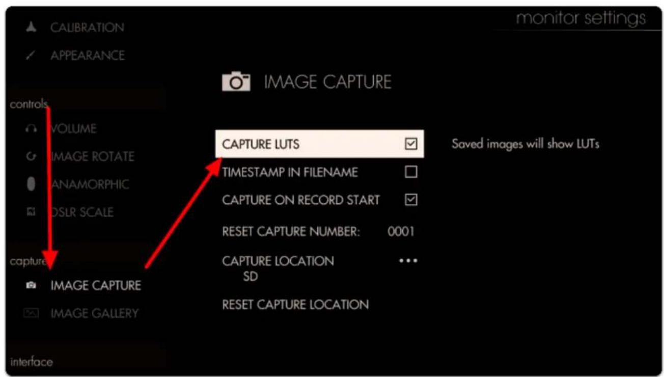
text_image
CALIBRATION APPEARANCE Image CAPTURE controls VOLUME IMAGE ROTATE ANAMORPHIC DSLR SCALE CAPTURE IMAGE CAPTURE IMAGE GALLERY interface CAPTURE LUTS TIMESTAMP IN FILENAME CAPTURE ON RECORD START RESET CAPTURE NUMBER: 0001 CAPTURE LOCATION SD RESET CAPTURE LOCATION Saved images will show LUTsFlip back over to the page with Image Capture applied so that we can take a snapshot.
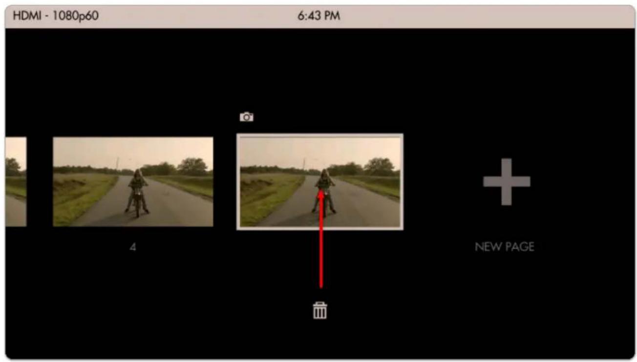
text_image
HDMI - 1080p60 6:43 PM 4 + NEW PAGELet's add a Look (3D LUT) to the page via Add Tool > Overlay > Look

text_image
OVERLAY LOOK IMAGE OVERLAY IMAGE CAPTURE AUDIO METERS SDI METADATA Apply a color-graded look (3D LUT) to your image; set up on multiple pages to quickly switch between different looks.Next select a Look/3D LUT from an SD card or the internal memory.

If you wish to learn how to create your own Look/3D LUT in Davinci Resolve, follow our video tutorial!
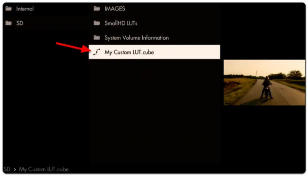
text_image
Internal SD IMAGES SmallHD LUTs System Volume Information My Custom LUT.cube SD > My Custom LUT.cubeWe're finally ready to take a snapshot! Select Image Capture that's already in the toolbar.
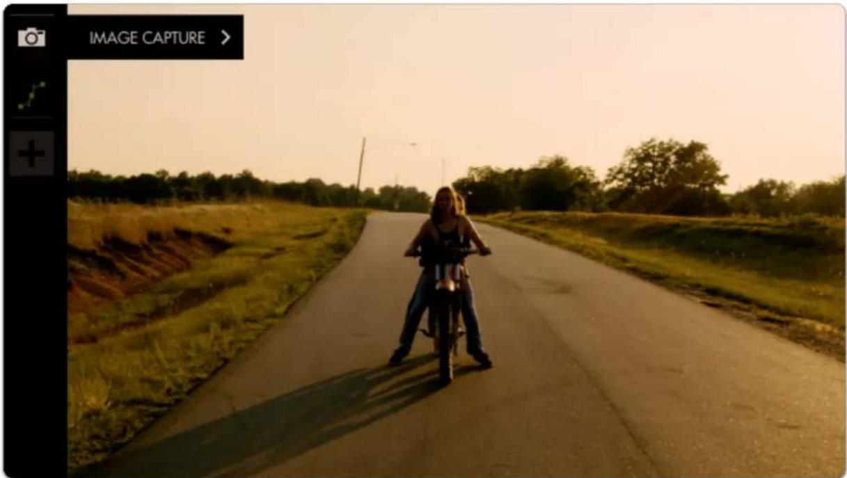
natural_image
A person riding a motorcycle on a rural road beside a dirt path, with trees and open land in the background (no text or symbols visible)A grey snapshot overlay will appear; click the joystick or tap the screen and the overlay turns green, indicating a snapshot has been taken. The screen will also appear to flicker.
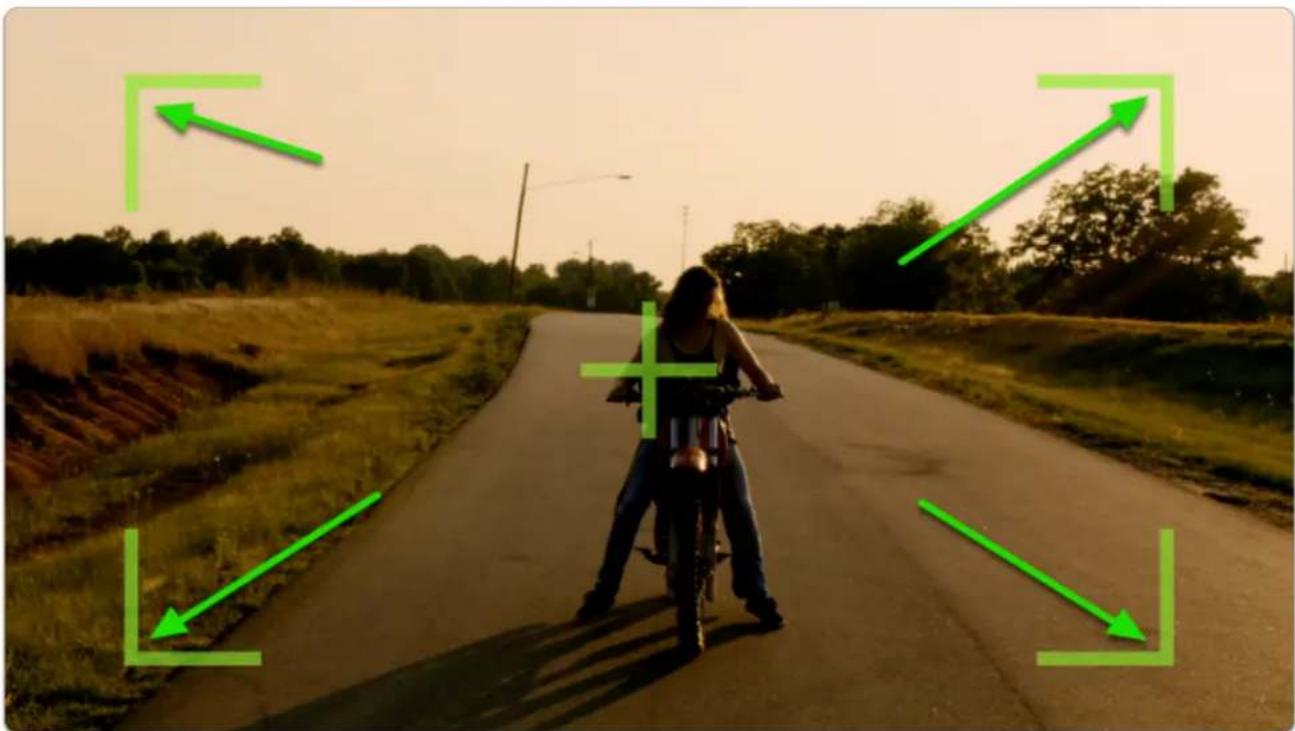
natural_image
Person riding a motorcycle on a rural road at sunset, with green directional arrows and no visible text or symbols.
SmallHD User Manual
To browse through your captured images on the monitor, you can access the Image Gallery back from within the global Settings menu.
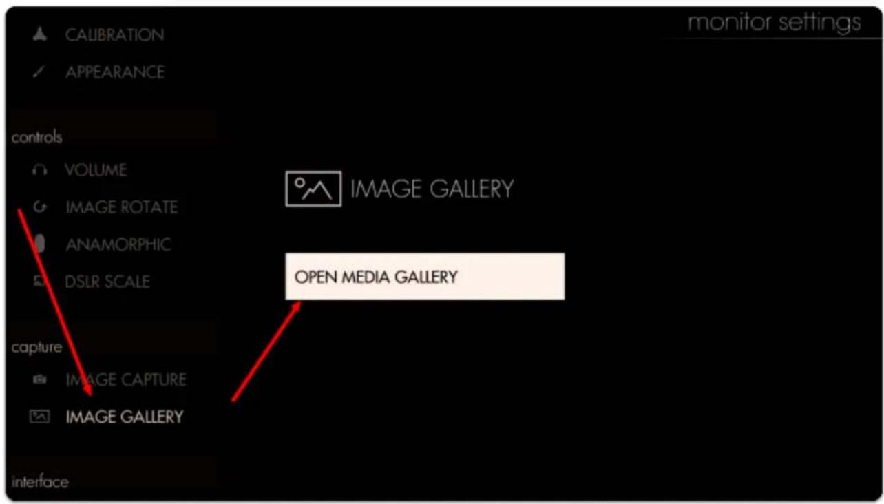
text_image
CALIBRATION APPEARANCE controls VOLUME IMAGE ROTATE ANAMORPHIC DSLR SCALE IMAGE GALLERY OPEN MEDIA GALLERY capture IMAGE CAPTURE IMAGE GALLERY interface monitor settingsThe default capture location is under the SD/IMAGES, so navigate to this folder by selecting the appropriate folders in the Image Gallery.
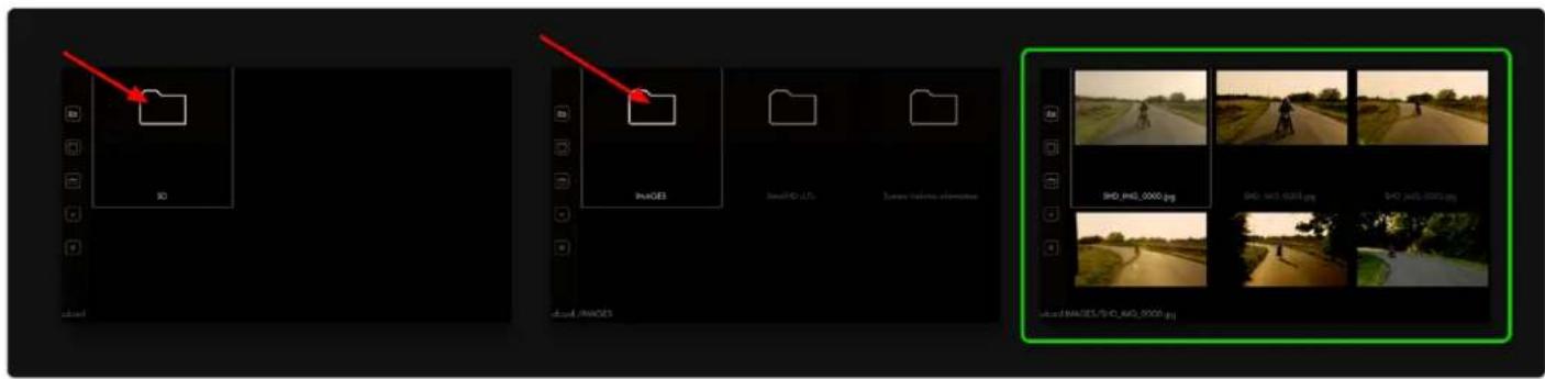
text_image
3D PHASES SHD-010_0000.jpg SHD-010_0001.jpg SHD-010_0002.jpg SHD-010_0003.jpg SHD-010_0004.jpg SHD-010_0005.jpg SHD-010_0006.jpgNote the difference in color grade between our first capture and each additional capture due to the application of the Look/3D LUT.
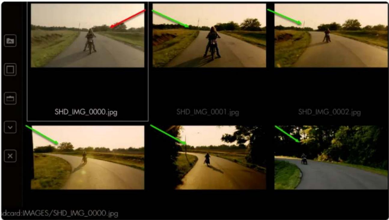
text_image
SHD_IMG_0000.jpg SHD_IMG_0001.jpg SHD_IMG_0002.jpgSelect any image to display it in full screen.
*If you are having issue displaying the image full screen on the LITE series, use the Image Overlay tool at 100% to preview your images.
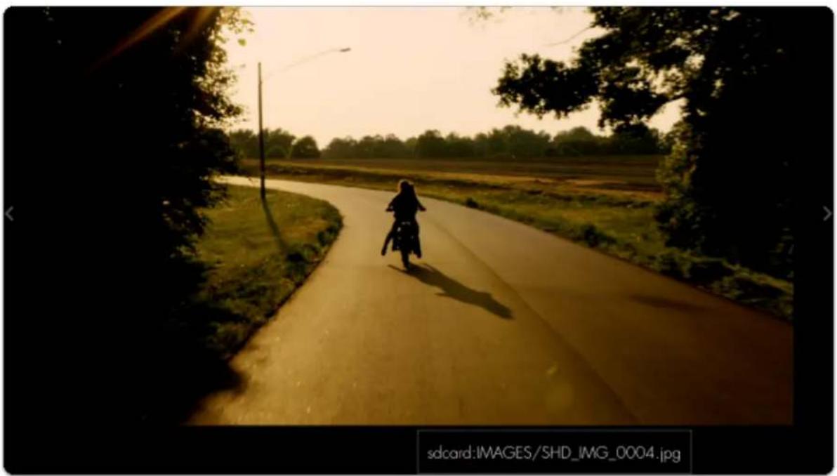
natural_image
Silhouette of a person riding a motorcycle on a rural road under a golden sky, surrounded by trees and fields (no text or symbols visible)
SmallHD User Manual
At this point you could apply any screenshot as an Image Overlay for help with continuity/shot matching or plug the SD card into a computer to backup/save/edit.
Audio Meters

text_image
Audio MetersMonitor up to 8 channels of audio with a built-in clip warning.
Audio Meters - Settings
Access Audio Meters tool settings by navigating right or pressing the right arrow when Audio Meters is highlighted in the tool list.
On
Toggles the Audio Meters Off/On. You can also do this on the tool bar. Select the tool and activate or deactivate it as desired. Green tools are active, they are Grey when inactive.
Size
Adjust the size of the Audio Meters to make way for other tools or for better visibility when viewing from a distance. The range is from 20% to 100% and this translates to horizon real estate. It will scale form the position/ location you have selected.
Channels
Adjust the amount of audio channels you wish to monitor - up to 4x stereo (8 channels in total)- which stack vertically.
Location
Arrange the Audio Meters on-screen using various pre-set locations to make way for other tools or the image itself. You have 6 options:
TOP - Left, Center, Right
BOTTOM - Left, Center, Right
Opacity
Set the transparency/opacity of the Audio Meters.
Audio Meters - Quick Start
In this section we will add Audio Meters to a page so we can keep an eye on levels.
From any page with a feed, click the joystick or tap the screen to bring up 'Add New Tool' and navigate to Overlay > Audio Meters and select to add it to the current page.
This may be all you need at this point, but let's increase the size of the meter for better viewability.
When 'Audio Meters' is highlighted, press the joystick right or tap the right arrow to edit its settings.
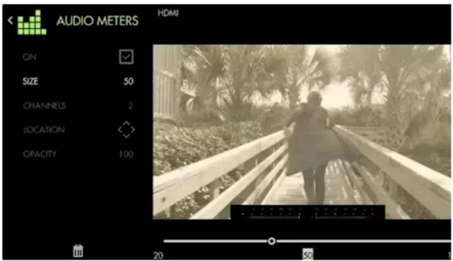
text_image
AUDIO METERS HDMI ON SIZE 50 CHANNELS 2 LOCATION OPACITY 100 20 50
SmallHD User Manual
Select 'Size' and bring it up to 100 for a full-width audio meter.
You can also increase the amount of channels being displayed if your production requires it.

If you don't wish to have Audio Meters covering your image, you can scale the image to make room with Size & Position.
Metadata
SDI Metadata
Displays a small information bar containing metadata information being sent over HDMI or SDI such as timecode and tally flags. Useful for ensuring the camera is recording without having to take your eyes off the monitor.

Not all cameras support outputting metadata over HDMI or SDI. Some cameras may not have metadata enabled by default. Please refer to your camera's user manual for information on supported metadata and how to enable this feature.
Metadata - Settings
Access Metadata settings by pressing to the right when the tool is highlighted.
On
Toggles Metadata Off/On. You can also do this on the tool bar. Select the tool and activate or deactivate it as desired. Green tools are active, they are Grey when inactive.
Timecode
Enables display of the camera's timecode being sent over HDMI or SDI. This will appear in a small black box in the location selected.
Record
Enables display of the camera's record flag being sent over HDMI or SDI. This displays as a red rectangle around the edge of the monitor frame.
Location
Arrange the SDI Metadata on-screen using various pre-set locations to make way for other tools or the image itself.
You have 6 locations:
TOP - Left, Center, Right BOTTOM - Left, Cetner, Right
Opacity
Set the transparency/opacity of the Metadata.
Metadata - Quick Start
Let's add Metadata to a page.
From any page displaying an SDI signal, click the joystick or tap the screen and select Add New Tool > Overlay > Metadata.
By default timecode and record tally are enabled, meaning you will be able to view your camera's specific timecode value and an indicator if the camera is currently recording.
Tools - Scale
Crop & Scale
Crop & Scale
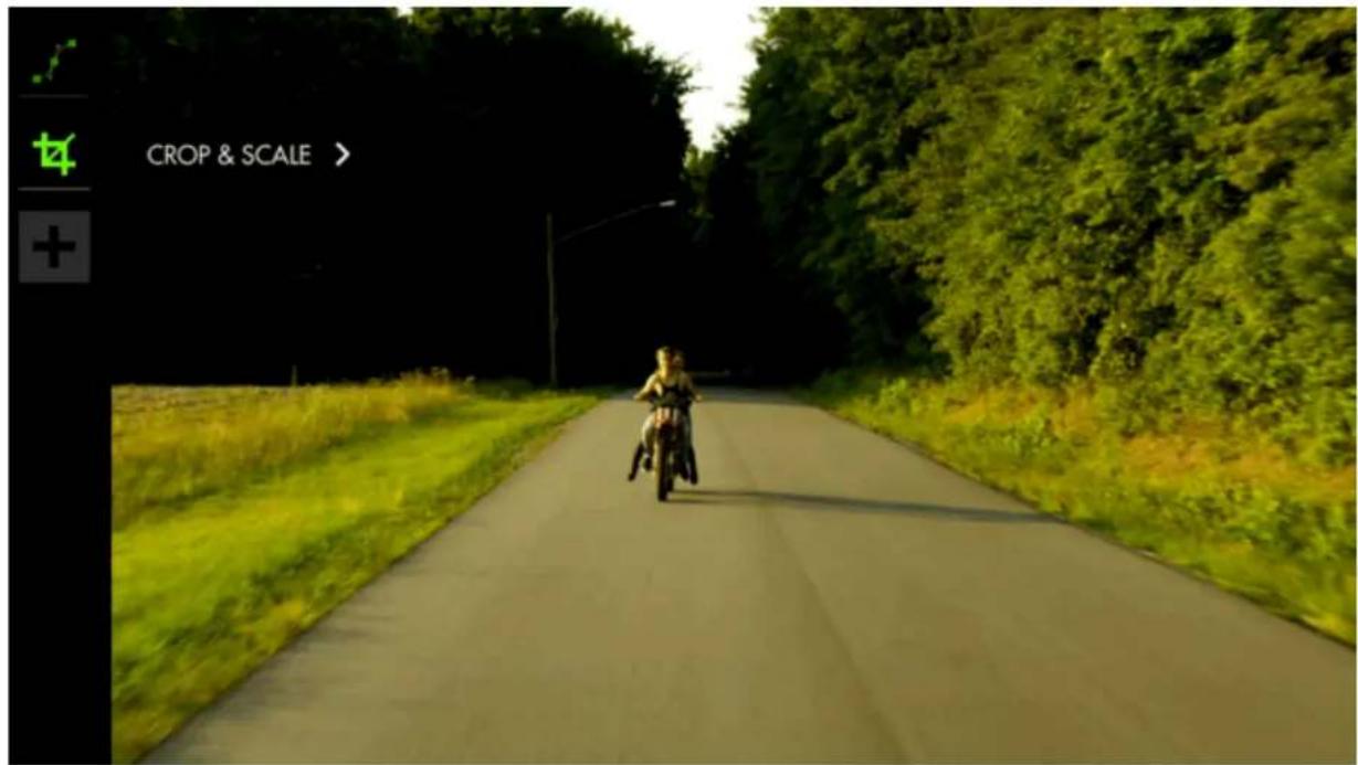
text_image
CROP & SCALE >If you plan to crop your image, for example shooting interviews in 4K and zooming in post for the 'close up' or for cameras that don't send a fullscreen feed to the monitor, this tool lets you pre-visualize a custom crop and will automatically scale up the remaining portion to fill the page.
You will need a video signal to use this tool.
Crop & Scale - Settings
Access Crop & Scale tool settings menu by navigating right or pressing the right arrow when Crop & Scale is highlighted in the tool list.
Once you make your adjustments, the image will become full screen. When in the tool module, you will see a red guide to show where your selected frame line is.
On
Toggles Crop & Scale Off/On. You can also do this on the tool bar. Select the tool and activate or deactivate it as desired. Green tools are active, they are Grey when inactive.
Center Crop
If you wish to crop your image symmetrically, select this option. It will crop down to the center point.
\*Width
When 'Center Crop' is selected, this will adjust the width of the cropped area symmetrically.
\*Height
When 'Center Crop' is selected, this will adjust the height of the cropped area from the center of the image.
Left
When 'Center Crop' is unselected, this will adjust the amount of cropping being applied to the left-hand side of the image.
Right
When 'Center Crop' is unselected, this will adjust the amount of cropping being applied to the right-hand side of the image.
Top
When ‘Center Crop’ is unselected, this will adjust the amount of cropping being applied to the top of the image.
Bottom
When ‘Center Crop’ is unselected, this will adjust the amount of cropping being applied to the bottom of the image.
Crop & Scale - Quick Start
In this section we will make highly efficient use of screen space by employing Crop & Scale to preview a 2.39 cinemascope aspect ratio and a full-width Waveform with no overlapping elements or wasted space.
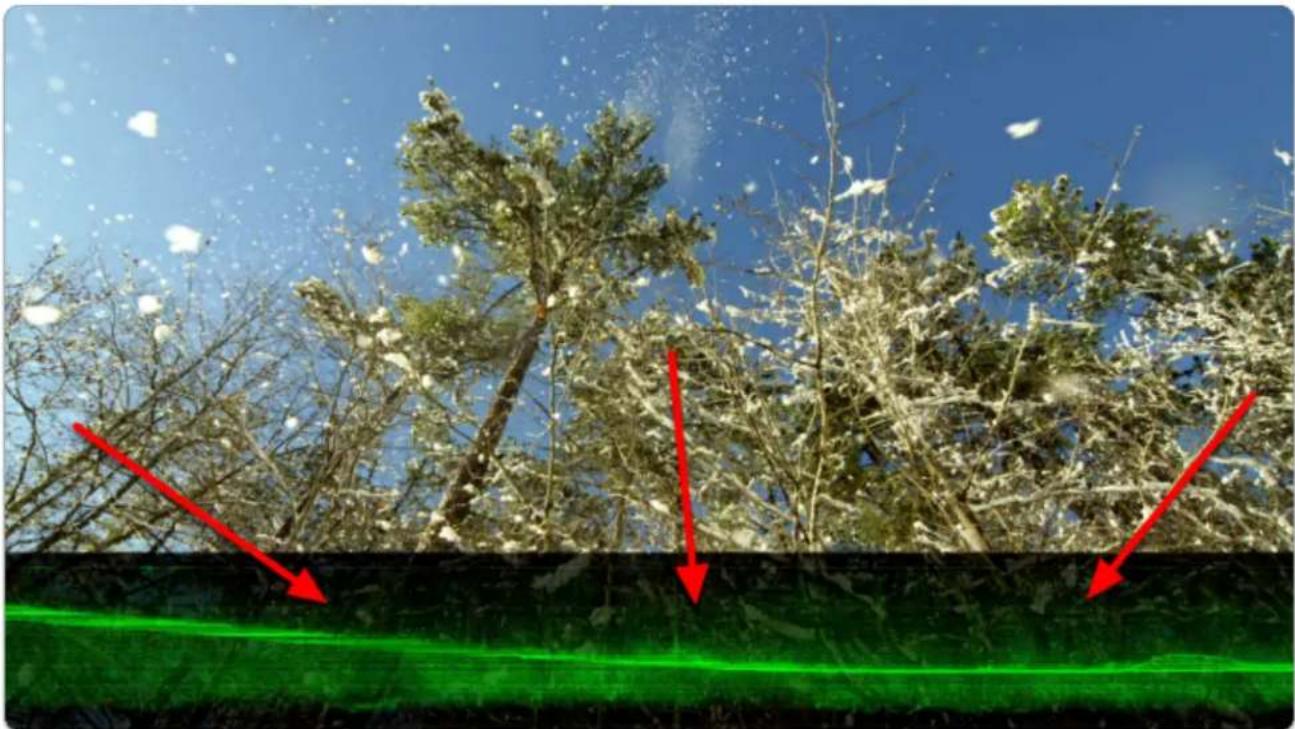
natural_image
Snow-covered tree branches under a clear blue sky, with red arrows pointing to a green textured surface (no text or symbols)From any page with a feed, click the joystick or tap the screen to bring up 'Add New Tool'.
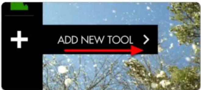
text_image
ADD NEW TOOL >Navigate to Scale > Crop & Scale and select the '+' to add it to the current page.
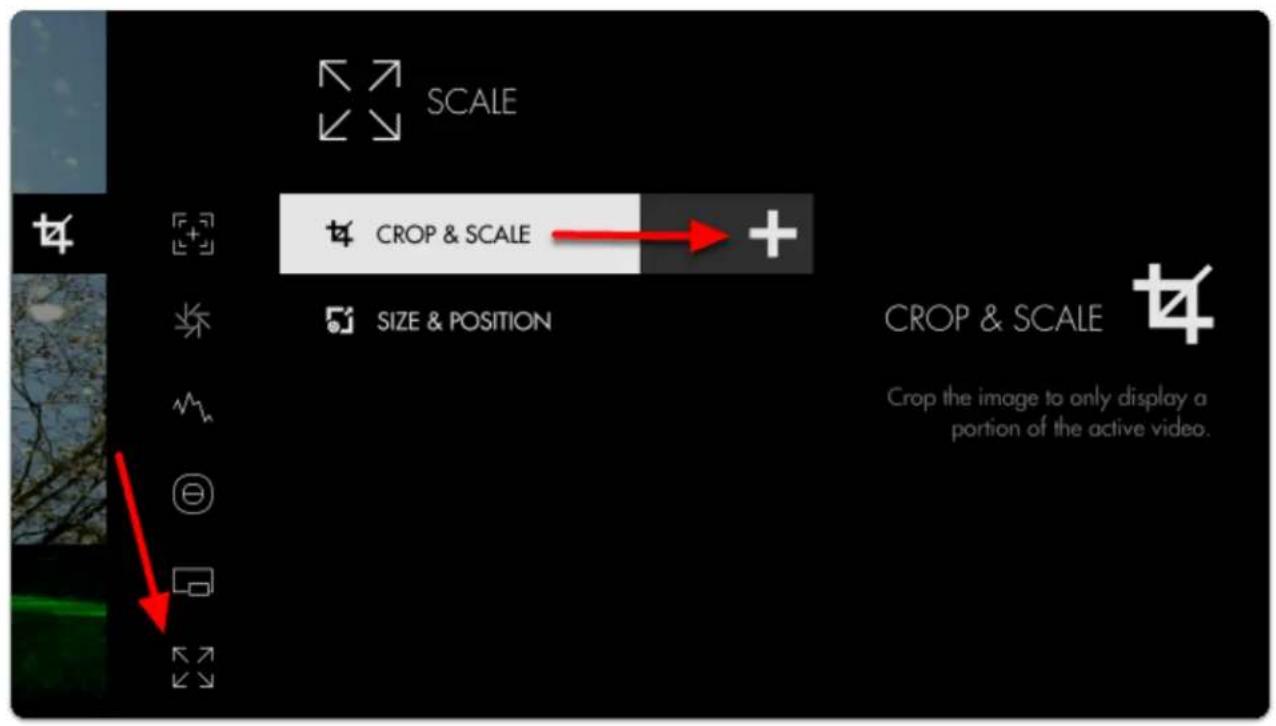
text_image
SCALE CROP & SCALE SIZE & POSITION CROP & SCALE Crop the image to only display a portion of the active video.Once added you can edit the settings by navigating right or tapping the right arrow when 'Crop & Scale' is highlighted.
Navigate to HEIGHT.

Take note of the red border - anything outside this area gets cropped when exiting the tool.
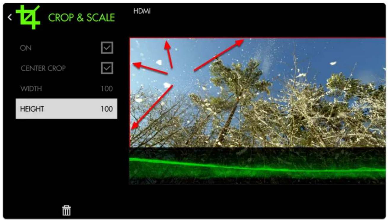
text_image
CROP & SCALE HDMI ON CENTER CROP WIDTH 100 HEIGHT 100Decrease the HEIGHT to 75% which simulates the same cropped area as a 2.39:1 aspect ratio.
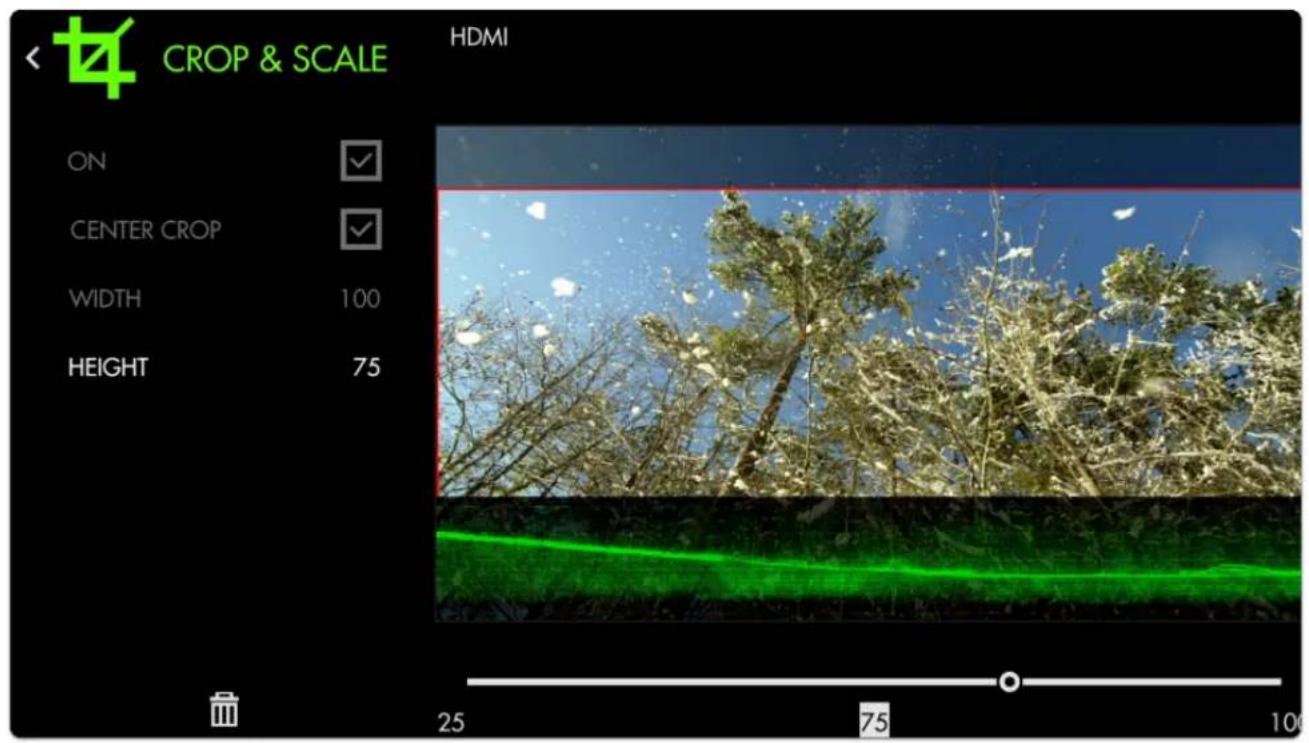
text_image
CROP & SCALE HDMI ON CENTER CROP WIDTH 100 HEIGHT 75 25 75 100Press the Back button or tap the top-left arrow to back out of the edit menu.

SmallHD User Manual
Now our image is being cropped to the setting we chose. We just need to shift it upwards with Size & Position so it no longer overlaps with the Waveform.
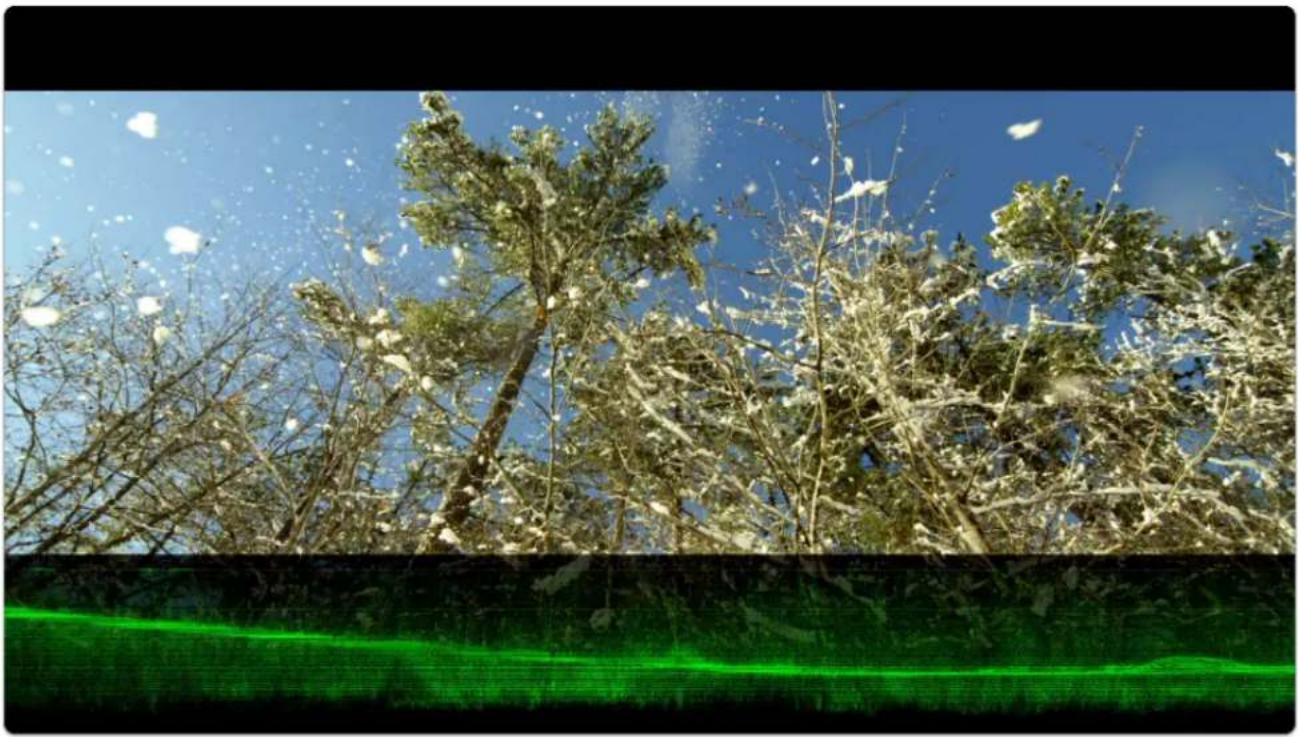
natural_image
Snow-covered tree branches against a clear blue sky, with a green laser beam in the foreground (no text or symbols visible)Add Size & Position via Add New Tool > Scale > Size & Position.
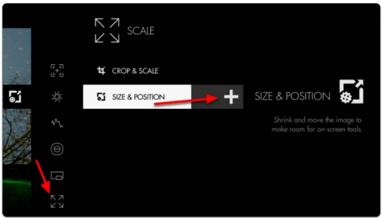
text_image
SCALE CROP & SCALE SIZE & POSITION + SIZE & POSITION Shrink and move the image to make room for on-screen tools.
SmallHD User Manual
Once added, open the edit menu by tapping or pressing right on the Size & Position tool.
Select LOCATION and then tap towards the top of the image or press up on the joystick.
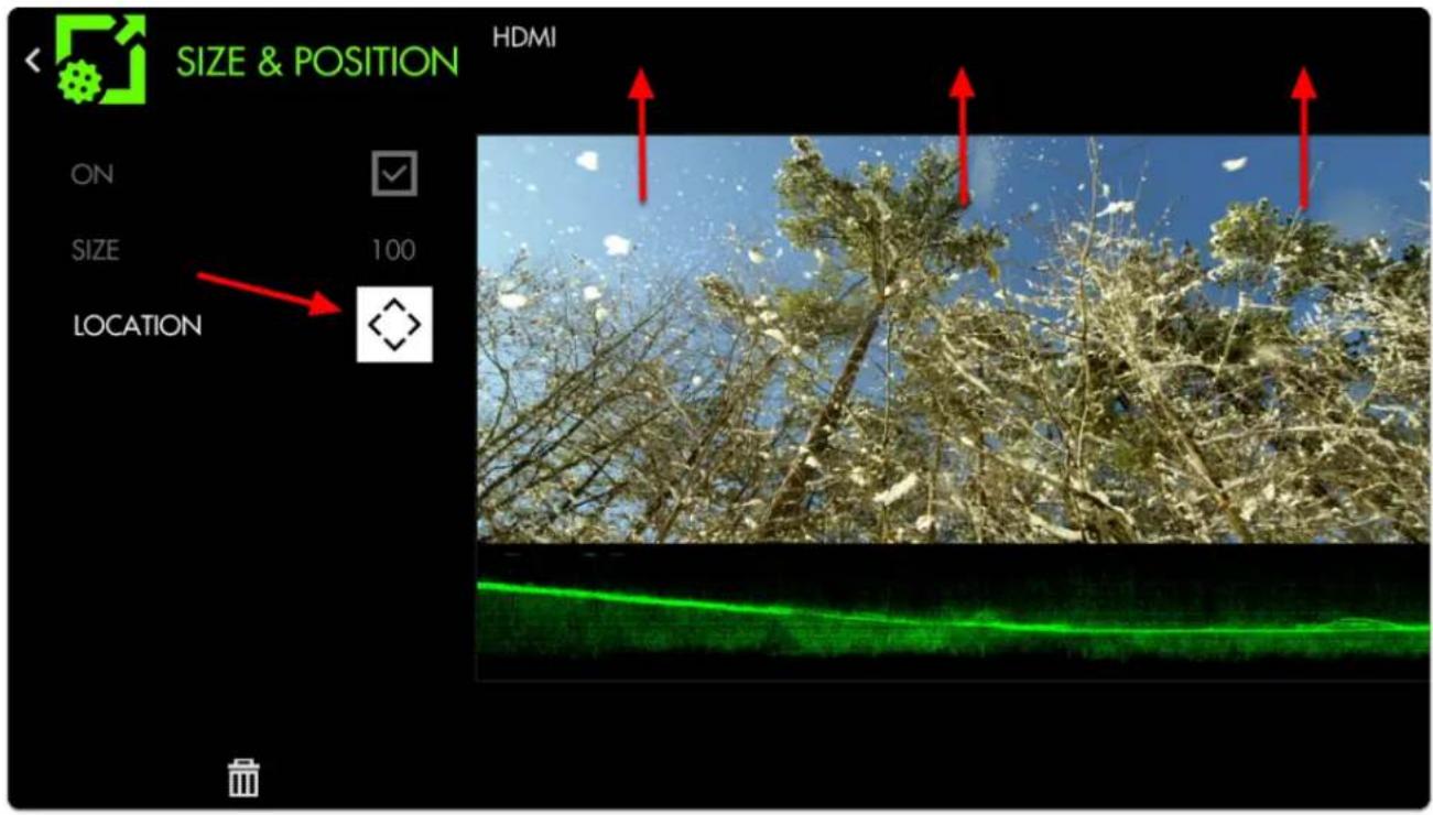
text_image
SIZE & POSITION HDMI ON SIZE 100 LOCATIONBack out of the edit menu for a full-screen view of a 2.39 cinemascope aspect ratio accompanied by a full-width Waveform!
Size & Position

text_image
Size & PositionResize and position your image to accommodate other features you may wish to simultaneously view, such as scopes or audio meters. This will be helpful for users that want to keep multiple tools on the same screen, rather than using pages.
Size & Position - Settings
On
Enables/disables the Size & Position tool. You can also do this on the tool bar. Select the tool and activate or deactivate it as desired. Green tools are active, they are Grey when inactive.
Size
Adjusts the size of the image proportionally within a page compressing toward the center of the selected location.
Location
After scaling the image, use this to position it where desired. There are 9 positions:
TOP - Left, Center, Right
MIDDLE - Left, Center, Right
BOTTOM - Left, Center, Right
Size & Position - Quick Start
In this section we will use Size & Position to help arrange the image so that a full-width Waveform will not overlap the footage, enabling a clean view of the picture and the scope on the same page.
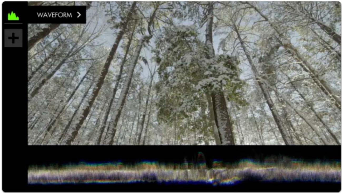
text_image
WAVEFORM >I have already added a Waveform to an empty page and adjusted its height from 50 down to 25 to make a bit more room for the image, but it is still covering a portion of the picture which we can address with Scale & Position.
Click the joystick or tap the screen to bring up 'Add New Tool'.
Navigate to Scale > Size & Position & select the '+' to add it to the current page.
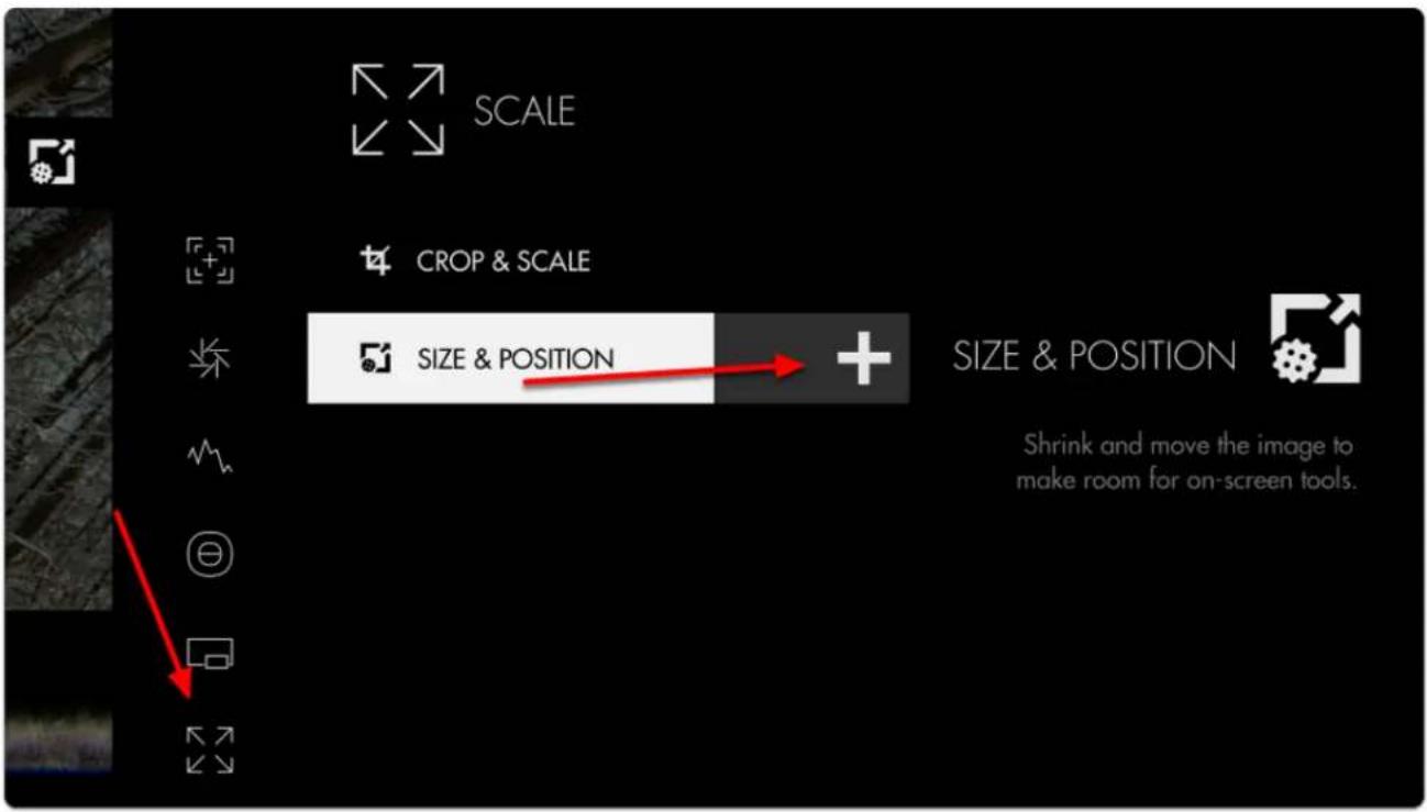
text_image
SCALE CROP & SCALE SIZE & POSITION + SIZE & POSITION Shrink and move the image to make room for on-screen tools.Once added you can edit the settings by navigating right when 'Size & Position' is highlighted.
Navigate to SIZE and adjust it from 100 to 75- you will notice the image scaling from its' center point.

Because the Waveform is scaled to 25% height, the image fits perfectly when scaled to 75%.
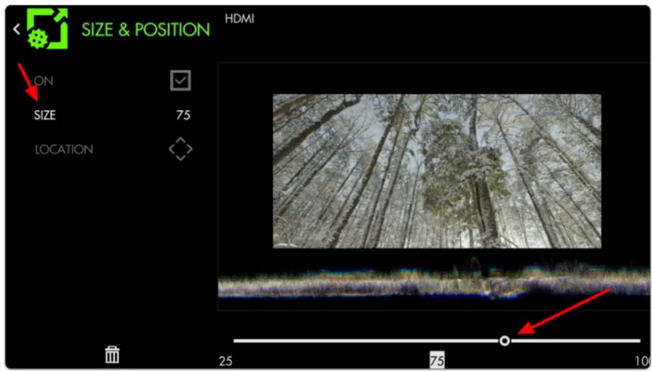
text_image
SIZE & POSITION HDMI ON SIZE 75 LOCATION 25 75 100Now move the image to the top of the frame by selecting LOCATION and pressing up on the joystick or tapping the top portion of the image. This leaves us with an unobstructed view of the Waveform.
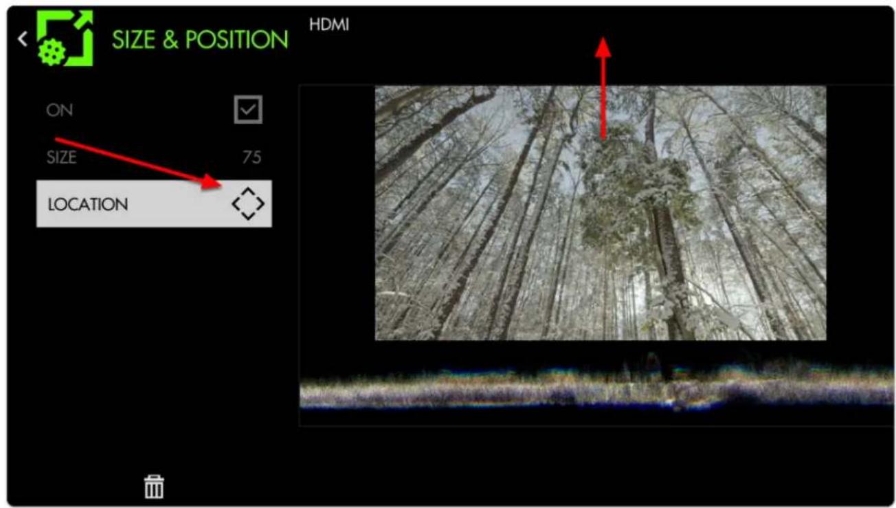
text_image
SIZE & POSITION HDMI ON SIZE 75 LOCATION
SmallHD User Manual
Press Back or tap the left arrow at the top right hand corner to exit.
Next we edit the Waveform and scale its WIDTH to 75 to match the width of the image.

text_image
WAVEFORM HDMI ON IGNORE LOOK STYLE RGB LAYOUT FULL SCREEN WIDTH 75 HEIGHT 25 LOCATION 100 75 80 25 0 5 75 100We now have an unobstructed view of our image and its corresponding Waveform!
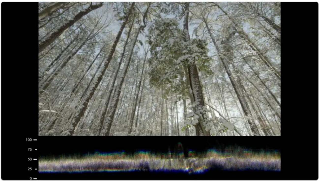
natural_image
Dense forest scene with tall trees and snow-covered ground, overlaid with a grayscale color gradient bar at the bottom (no text or symbols)At this stage you can use the LOCATION adjustment to add & arrange more tools such as a Vectorscope and Histogram if you wish.
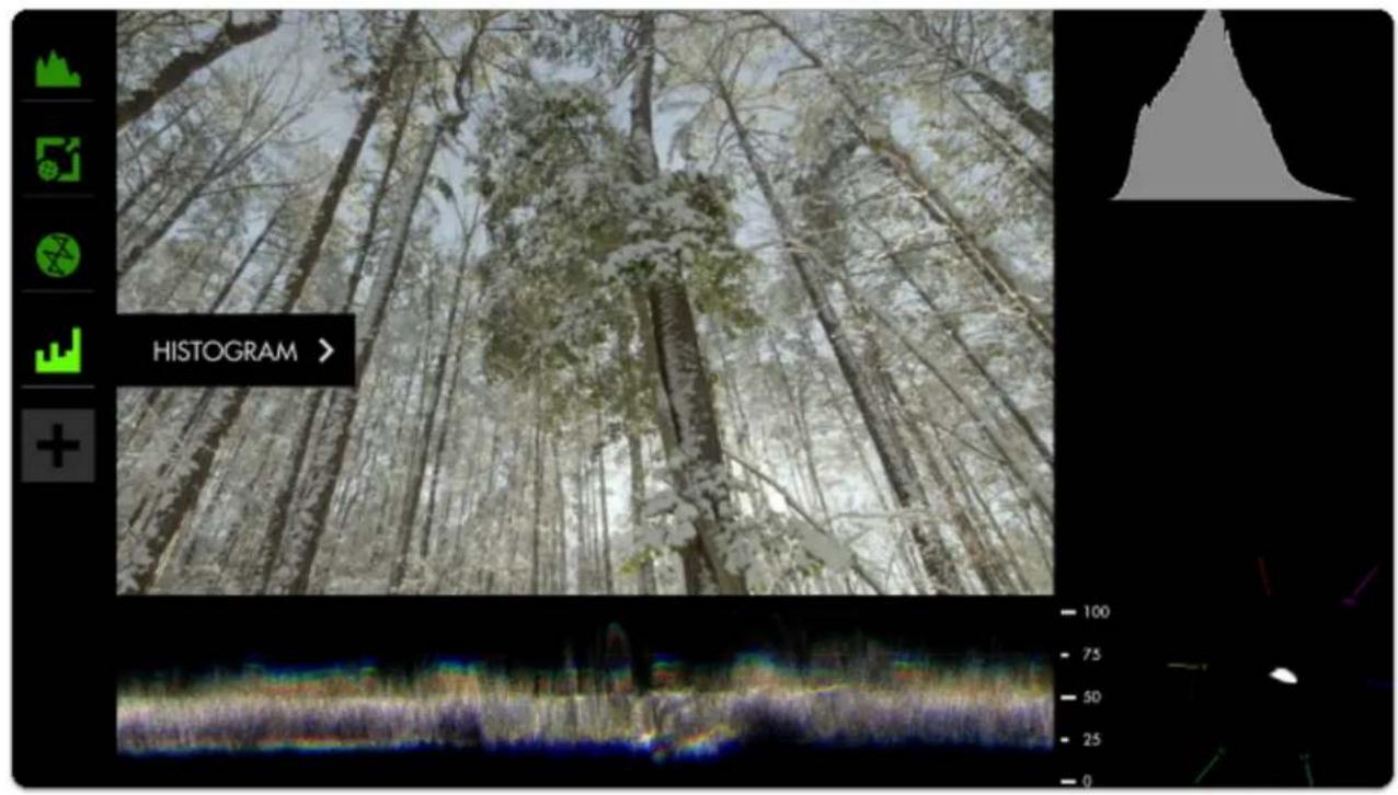
text_image
HISTOGRAM >Anamorphic
Anamorphic video is a technique where an image is squeezed horizontally during the recording process. On film sets this is done to make better use of the film or sensor's vertical space using specialty lenses. It is also often seen when footage originated in HD needs to pass through SD equipment. In all cases an anamorphic de-squeeze can restore footage to its native aspect ratio, although lost resolution is not recovered. Lost horizontal resolution is generally not perceptible to human eyes; lost vertical resolution (such as from HD footage being sent through SD equipment) may be noticeable.
Anamorphic - Settings
On
Enables/Disables Anamorphic de-squeeze
Input Video

The monitor will automatically attempt to determine the correct aspect ratio for the video from its resolution and any flags in the video stream. In some cases those flags are incorrect and this tool can be used to fix the video.
Select the aspect ratio of the video input (4:3 or 16:9), regardless of what the monitor identifies the input video as being. (This will squeeze a 16:9 image into a 4:3 frame for example if 4:3 is selected and you are sending it a 16:9 image).
If you need to correct video that has been incorrectly identified as 16:9 or 4:3, this may be the only setting you need to adjust.
Desqueeze
Choose the amount to de-squeeze your input by. Choices are 1×, 1.33× (this will stretch a 4×3 video back to 16×9), 1.5×, 1.66×, 1.79×, 2×, or Custom.
Selecting Custom from the Desqueeze setting will add this additional setting. It brings up a slider allowing you to adjust your anamorphic de-squeeze by a custom value between 1.00× to 3.00×. Please note that this is an adjustment factor based off your video input, not the aspect ratio you are working in.
Anamorphic - Quick Start
Anamorphic was added as a tool in firmware version 3.5.0. Previous firmware versions had a limited Anamorphic de-squeeze function in the monitor Settings under Controls.
From any page, click the joystick or tap the screen to bring up Add New Tool.
Navigate to Scale > Anamorphic and choose Add to This Page or Add to All Pages
If the footage connected to your monitor is all coming from an anamorphic source you may want to add this tool to all pages
Tools - Addons
RT Teradek Motion Overlay
https://support.teradek.com/hc/en-us/articles/360020392513-Teradek-RT-SmallHD-Integration
Below are steps to activate the Lens Data Overlay feature.
Before continuing, please see the following requirements:
If you have a CTRL.1, you need to purchase a Lens Mapping License. If you have a CTRL.3, the license is already included.
- A compatible SmallHD/Teradek RT Controller Interface Cable
Be sure you purchase the appropriate cable for your monitor. can be purchased at teradek.com
Cables
UPDATE YOUR CONTROLLER AND MONITOR TO THE LATEST FIRMWARE
MONITOR:
- Visit https://www.smallhd.com/community/os3 and download firmware version 3.4.0 or later to a compatible SD card.
- Insert the SD card into the monitor.
- From the main screen, swipe left to access the monitor settings, then scroll down to the system menu and select firmware. You will then be prompted to install the firmware file from the SD card.
- Restart your monitor.
CTRL.1/CTRL.3:
- If you have a CTRL.1, be sure to purchase a lens mapping license before you continue. If you have a CTRL.3, the lens mapping license is already included.
- Visit https://teradek.com/pages/downloads#teradekrt and download version 1.1.0 or later of the RTFW application. Run the RTFW software once it completes the installation.
- Turn the controller off and connect it to your computer via a USB to mini-USB cable.
- Turn the controller back on. RTFW will automatically detect the controller.
- Click Update Device.
- If you have not yet activated lens mapping on CTRL.1, visit https://activate.teradek.com/ and enter your controller's UID to generate a license key.
- From the controller, navigate to LENS>LENSMAP and select one of the configured lens maps. If you have not yet created a lens map, follow the instructions here: https://player.vimeo.com/video/301290121
- Firmware 1.4 and earlier : Press the MENU button to return to the main menu, then navigate to ADV>SMALLHD. Select YES to activate SmallHD Comms.
- Firmware 1.5 and later: Press the MENU button to return to the main menu, then navigate to IO CONFIG, select SMALLHD, and press SET.
CONNECT A CABLE FROM THE CONTROLLER'S WIRED MODE CONNECTOR TO THE MONITOR'S USB PORT:
- 5-pin to micro-USB for Focus (part number 11-1469)
- 5-pin to 5-pin for 703/703 Bolt
- 5-pin to USB-A for larger monitors
CONFIGURE YOUR MONITOR:
- Tap the screen on the monitor and navigate to ADD NEW TOOL>ADD ONS.
- Select TERADEK RT.
- The Lens Map Overlay will appear on the right and move according to the controller's knob movements.
ABOUT:
- The Teradek RT tool appears when a lens map is selected. If no lens map is selected, no information will be displayed on the monitor.
- The focus units will match those configured on the controller unless overridden by the Focus Units option in the Teradek RT tool configuration.
- The overlay only displays the axis that is currently being controlled by CTRL.1.
Shotover Gimbal Overlay
Firmware Updates
OS3 Software Update

Latest version overview can be found here.
Compatibility
OS3 firmware is compatible with all current SmallHD monitors (FOCUS series monitors, 500 series monitors, 700 series monitors, Cine 7 series monitors, all Bolt monitors, 1300 series monitors, 1700 series monitors, 2400 series monitors, and 3200 series monitors).

OS3 is not compatible with legacy monitors (DP1, DP6, DP4, AC7, and DP7-PRO).
How to Install OS3 Firmware

CAUTION: Make sure you do not lose power during firmware update
Download the latest firmware update
- Click the .zip download file to extract the .bin (firmware file).
- Drag and drop the .bin file onto your SD card
• Card must be 16 GB or smaller
- Formatted as FAT or FAT32 for Windows, MS-DOS (FAT) for macOS (if partitioned, select the MBR Master Boot Record option under Scheme)
- Remove SD Card from computer or card reader attached to computer
- Insert SD card into your SmallHD monitor
- Turn on your monitor
- Swipe/toggle left to the monitor's Settings Menu
- Select "FIRMWARE" in Settings Menu and follow on-screen prompts
- Once the firmware is installed and the on-screen prompts tell you to reboot your monitor – Hold down the power button for at least 5 seconds and then release.
- Press the power button again to begin operating your SmallHD monitor with the new firmware installed.
How to Format an SD Card
You must format the SD card using a computer. The monitor cannot format the card.
Windows Instructions
Formatting a card in Windows
macOS Instructions
Format your card using Disk Utility.
Click Erase to begin the formatting process.
When choosing the format, be sure to select MS-DOS (FAT).
Samples & Tutorials
How to use Look (3D LUT) files with your monitor
How to auto-calibrate your monitor
*Please be aware that the SmallHD branded i1 Xrite probe has been discontinued. (2019)
The probe will work on some of our older products for the "Auto Calibration Function". The unit must have a USB port and be within the specs that the Probe will function with.
The Probe can be used with an intermediary (computer) as long as the Panel is below 1000 nit and is not recommended for OLED or HDR.
*You should calibrate your monitor at your own risk.
**The probe does NOT work will ALL SmallHD Products.
The Probe can work with the following models:
501, 502, 502 Bright (90%), 702 (90%), FOCUS, FOCUS 7 (90%), 1303 Studio, 1703 Studio/ P3/ P3X, 2403 Studio
How to make a LUT
TROUBLESHOOTING TIPS
All Monitors - SmallHD - Technical - Conversion LUTs
PROBLEM
Is there a way to get the LUTs pre-installed on my SmallHD Focus monitor from the monitor to my computer? In particular the one converting the slog-3 to a rec 709. Any chance I can get that one?
SOLUTION
Unfortunately that internal conversion is not made with a LUT. We recommend this free pack of utility/conversion LUTs, though, which includes S-Log3 to Rec 709:
https://luts.iwltbap.com/free-lut-log-to-rec709-and-rec709-to-log-conversion/#freeware
We also offer a free pack of look LUTs for download here:
https://www.smallhd.com/community/gradetrade
Keywords
LUTs, conversion, Log, S-Log, S-Log2, S-Log3, Rec 709, Rec 2020, DCI P3
Firmware Software – All – Troubleshooting - LUTs not displaying correctly
PROBLEM
My Luts are not displaying correctly. They either don't work or don't act right. one even makes the picture black and white. Why are these not working? Downloaded directly from Canon
SOLUTION
These luts appear to be in a different configuration that the monitor is used to seeing. This can be solved by converting this to a 3D lut. This can be done with a free program called Davinci Resolve. The instructions are below:
https://www.blackmagicdesign.com/products/davinciresolve/
- Drop the LUT file into your Davinci Resolve LUT folder; on a mac this is in:

SmallHD User Manual
(Mac HD) > Library > Application Support > Blackmagic Design > Davinci Resolve
or in Windows:
C:/ProgramData/Blackmagic Design/DaVinci Resolve/Support/LUT/
-
Select the Edit page at the bottom of the main window
-
Drag and drop a video clip from the desktop into the timeline - (any video clip will work, we will only use it to ensure the LUT actually gets applied)
-
Click on the Color page at the bottom of the main window
-
In the Node view in the upper-right, right-click the only node (01) and select LUTs > (location of your LUT from step 1) to apply the grade to the clip
-
You should see a grid icon appear at the bottom of the node indicating it has a 3D LUT applied.
-
Select the clip itself toward the middle-left of the main window (as opposed to the node at the upper-right)
-
Right-click and select 'Generate 3D LUT (CUBE)'

SmallHD User Manual
- Save to an SD card for use in SmallHD monitors and elsewhere (ensure that the file retains a .cube extension or the LUT will not be recognized by the monitor).
Keywords
Sony, Canon, fuji, panasonic, 3d, 1d, LUT, LUTS, camera, card, sd card, profile, loading,
How to use Tools - Case Study (Touchscreen)
USING TOOLS - CASE STUDY
Below we will walk through an example of adding a few tools: FOCUS ASSIST, CROSSHAIR,
We will start by making a new page into a 'focus + framing' page that we can flip to for composing our shot and nailing focus. This will include a focus assist, a crosshair for accuracy performing pan/tilt and custom frame guides for a cinemascope aspect ratio.
Navigate to Focus (1) > Focus Assist (2) and select the '+' (3) to add Focus Assist to this page.
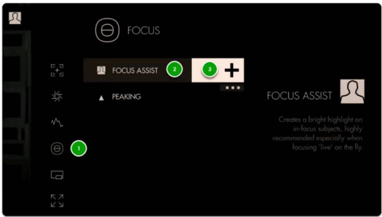
text_image
FOCUS FOCUS ASSIST 2 3 + PEAKING FOCUS ASSIST Creates a bright highlight on in-focus subjects, highly recommended especially when focusing 'live' on the fly.Focus Assist will paint a highlight around areas it determines to be in focus based on small/harsh changes in contrast.
The Peak Threshold is a bit high, meaning we are picking up extraneous edges on the back wall which are not quite in focus.
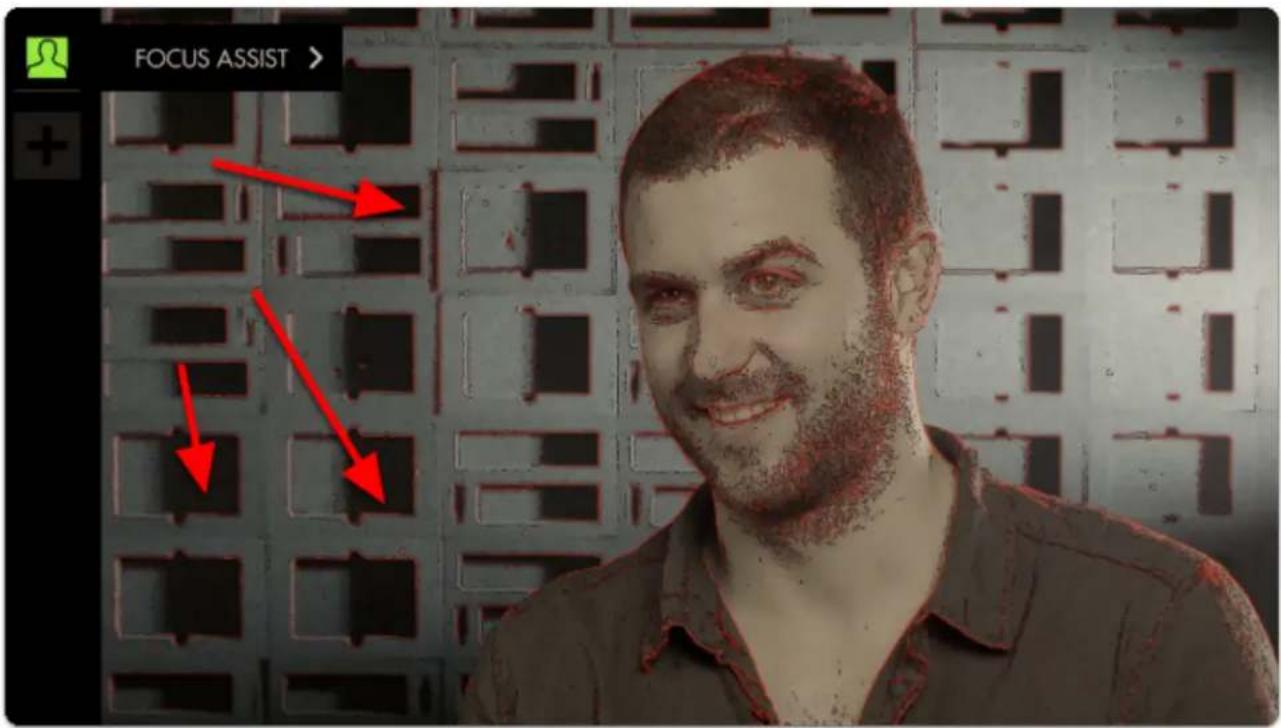
text_image
FOCUS ASSIST >To fix this, edit Focus Assist by tapping on it when it is highlighted in the tool bar, and navigate to Peak Threshold.
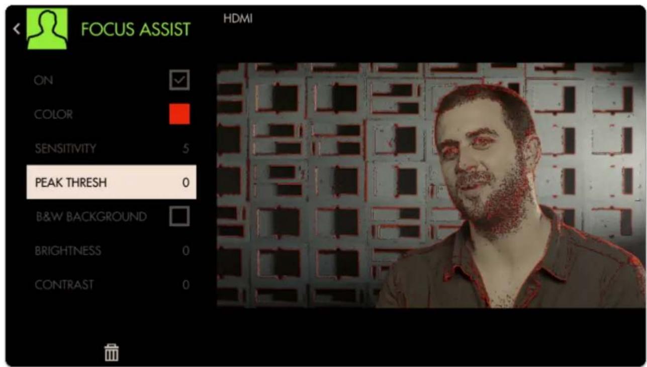
text_image
FOCUS ASSIST HDMI ON COLOR SENSITIVITY 5 PEAK THRESH 0 B&W BACKGROUND BRIGHTNESS 0 CONTRAST 0
SmallHD User Manual
Bringing Peak Threshold up to around 30 does a better job of causing only in-focus areas to activate the filter but this is ultimately a balance that may need tweaking depending on the camera/shot.
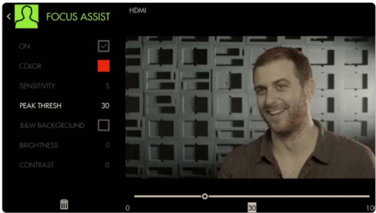
text_image
FOCUS ASSIST HDMI ON COLOR SENSITIVITY 5 PEAK THRESH 30 B&W BACKGROUND BRIGHTNESS 0 CONTRAST 0 0 30 10To make the effect more visible we can boost up the Sensitivity and change the Color.
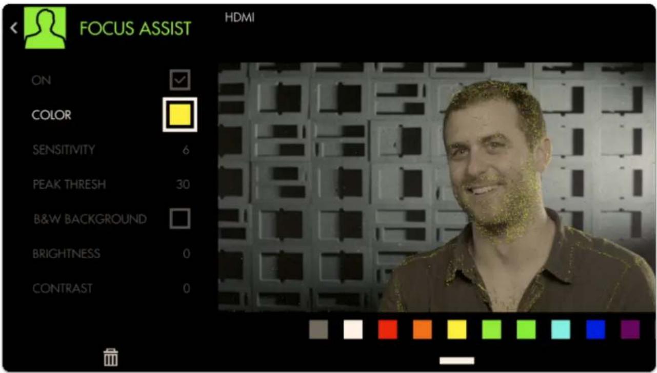
text_image
FOCUS ASSIST HDMI ON COLOR SENSITIVITY 6 PEAK THRESH 30 B&W BACKGROUND BRIGHTNESS 0 CONTRAST 0Next Add a Crosshair to the page by going through Add Tool > Frame > Crosshair
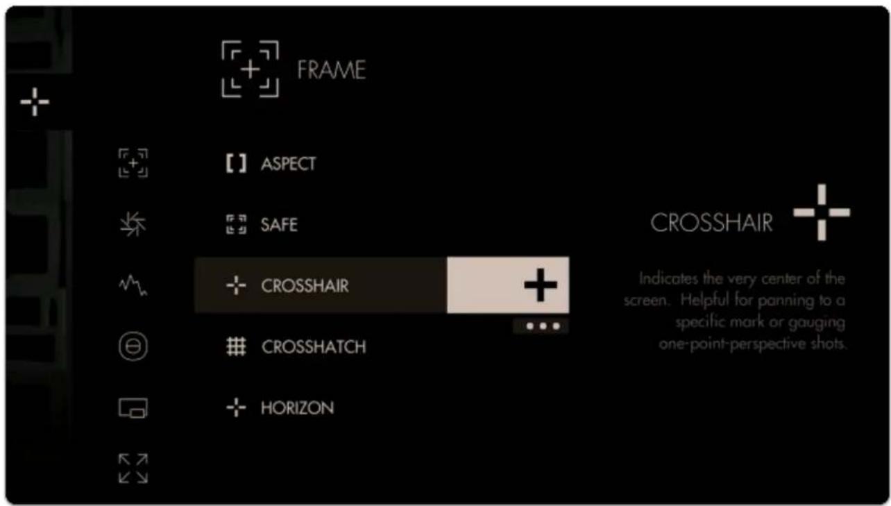
text_image
FRAME 【】 ASPECT SAFE CROSSHAIR CROSSHATCH HORIZON Indicates the very center of the screen. Helpful for panning to a specific mark or gauging one-point-perspective shots.
SmallHD User Manual
Finally we can add an Aspect Guide to all pages simultaneously by going to Add Tool > Frame > but this time press-and-hold Aspect briefly to keep the menu up then tap the three dots under the '+'.
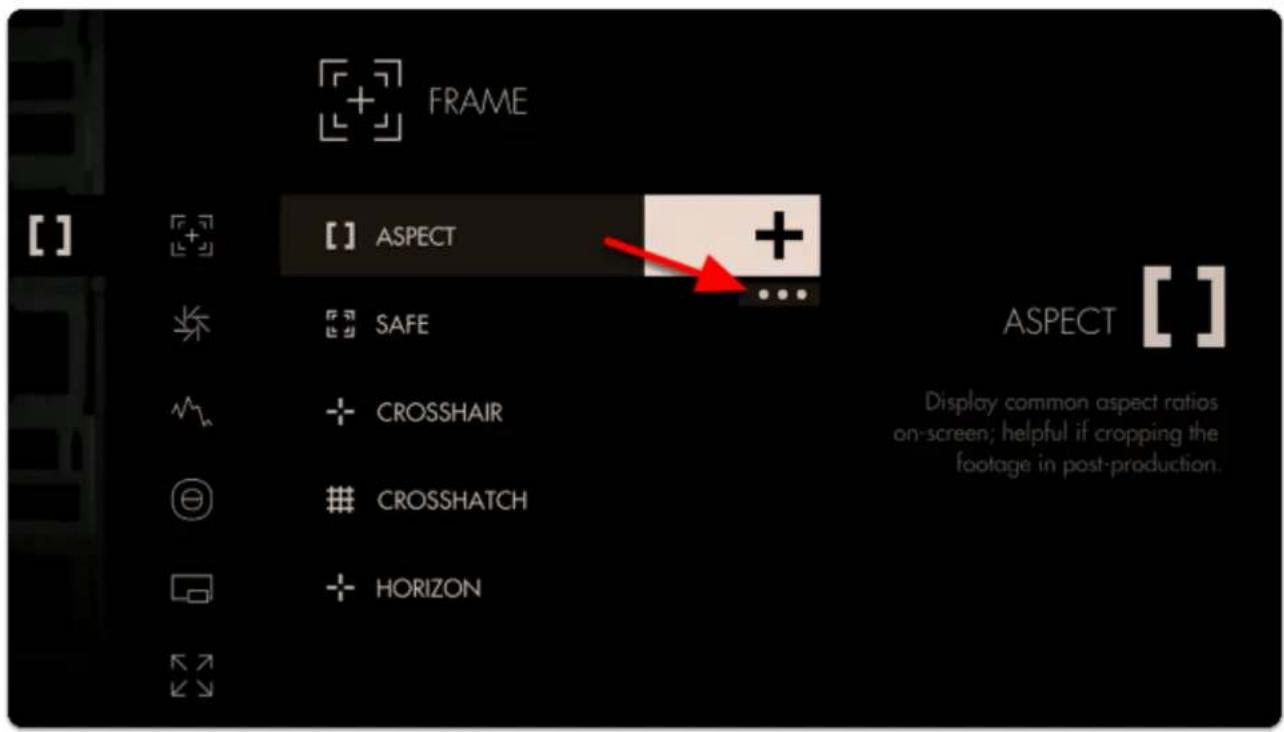
text_image
FRAME [ ] ASPECT + SAFE CROSSHAIR CROSSHATCH HORIZON ASPECT [ ] Display common aspect ratios on-screen; helpful if cropping the footage in post-production.Next tap the pictured icon to add Aspect Guides to all pages.
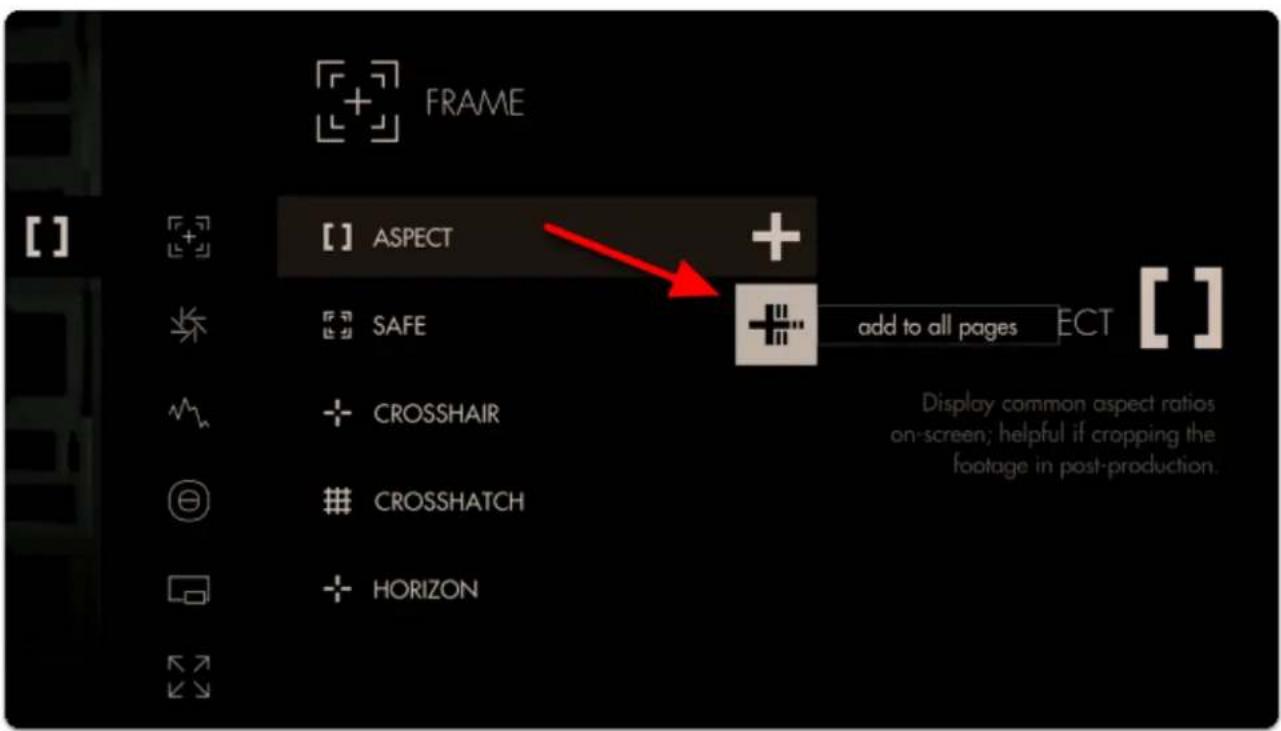
text_image
FRAME [ ] ASPECT + SAFE add to all pages ECT [ ] CROSSHAIR CROSSHATCH HORIZON Display common aspect ratios on-screen; helpful if cropping the footage in post-production.This will ensure you are able to view this tool on every page of the monitor, and any edits to it are made globally. Any tool can be added to all pages, including scaling adjustments and Look (3D LUT) files.
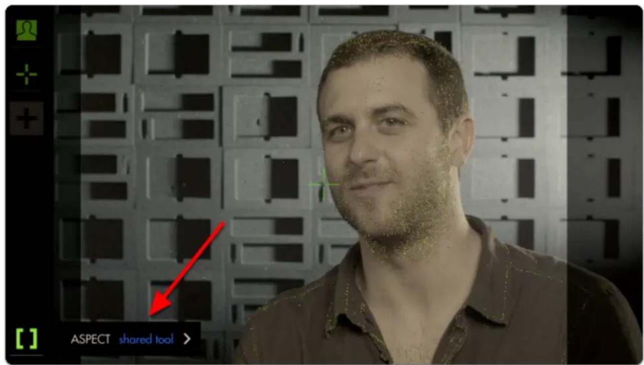
text_image
ASPECT shared tool >
SmallHD User Manual
By default the Aspect Guide is set up for a 4x3 aspect ratio for times when you're needing to preview the cutoff area of an old-school monitor.
Tap on the Aspect Guide to edit the tool.
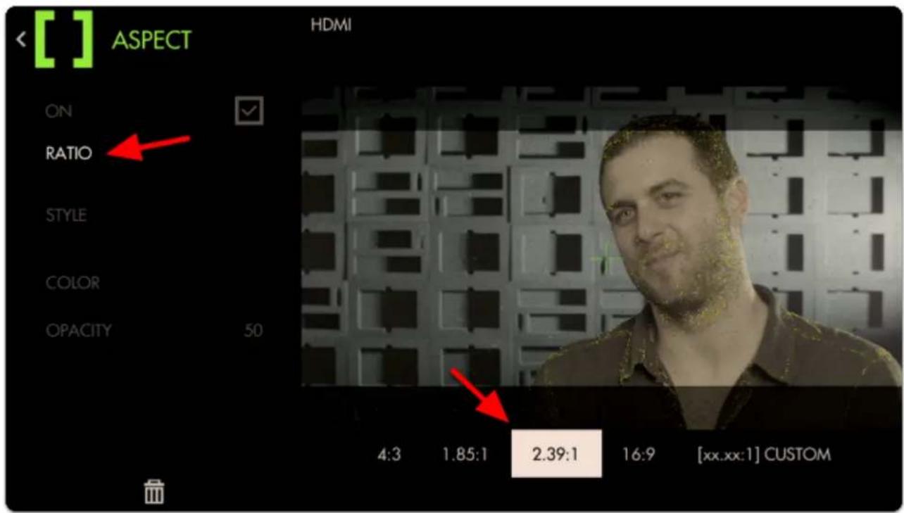
text_image
[ ] ASPECT HDMI ON RATIO STYLE COLOR OPACITY 50 4:3 1.85:1 2.39:1 16:9 [xx.xx:1] CUSTOMNavigate to "Ratio", select it and change the aspect ratio to "2.39" for cinemascope viewing.
Next move down to 'Opacity' and increase its percentage to view the guide becoming more opaque for a more visible effect.
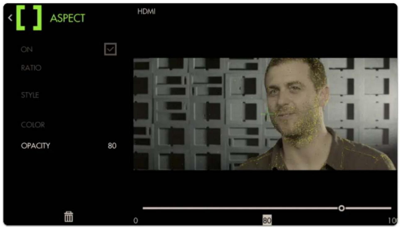
text_image
[ ] ASPECT HDMI ON ✓ RATIO STYLE COLOR OPACITY 80 0 80 10
Now we have a page that lets us focus our shot and frame it up properly for the common 2.39 aspect ratio.
Adding a Look (3D LUT) file to a page
Look Up Table files (3D LUTs) are a great way to visualize color grades without 'baking' anything into the footage - great for testing out different looks on set. Try our free 'Movie Looks' pack which can be placed on an SD card for use on your monitor or at any point in post production.
Let's add a Look to a new page - start by swiping down to navigate back to the zoomed-out view, move to the far right and select 'New Page' once more.
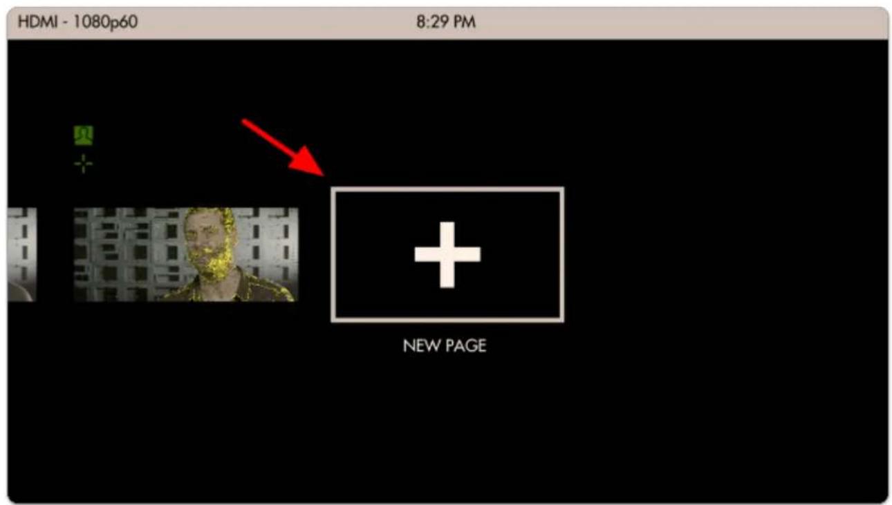
text_image
HDMI - 1080p60 8:29 PM NEW PAGENotice how when you add a new page, the Aspect Guide that was set for 'all pages' shows up automatically.
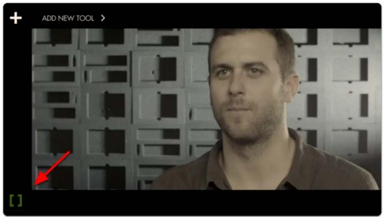
text_image
ADD NEW TOOL > [ ]
SmallHD User Manual
Tap to add a new tool, navigate to Overlay > Look and select the '+'.
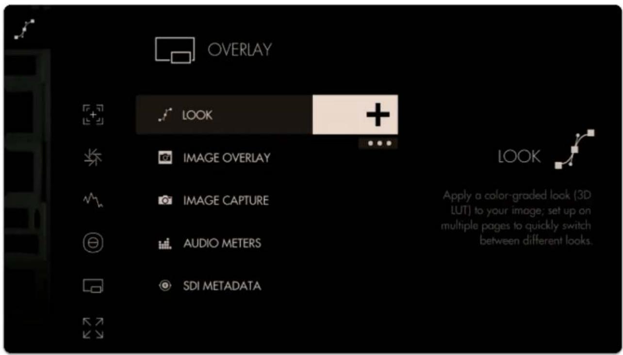
text_image
OVERLAY LOOK IMAGE OVERLAY IMAGE CAPTURE AUDIO METERS SDI METADATA Look Apply a color-graded look (3D LUT) to your image; set up on multiple pages to quickly switch between different looks.You will immediately be presented with a file browser to select a 3D LUT file. If you have any on an SD card, insert it into the monitor and it will be visible here.

SmallHD User Manual
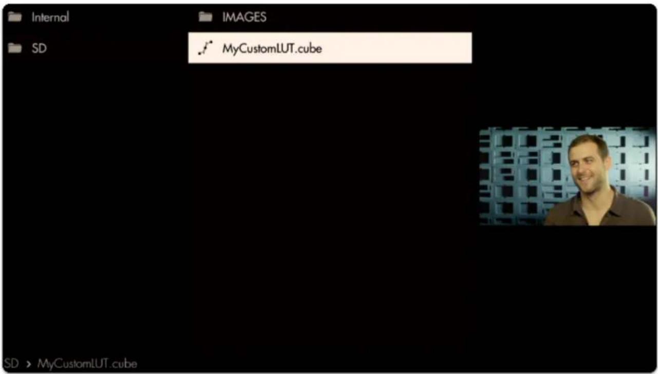
text_image
Internal IMAGES SD MyCustomLUT.cube SD > MyCustomLUT.cubeSelecting the LUT applies it to this page.
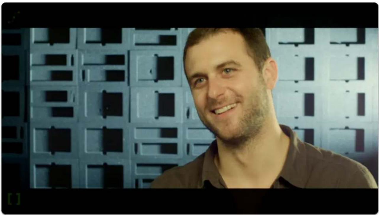
natural_image
Portrait of a smiling man with short hair, wearing a brown shirt, standing in front of a dark grid-patterned wall (no text or symbols visible)
natural_image
Portrait of a man with short hair against a blue grid-patterned background (no text or symbols visible)
Adding several LUTs to several pages can be a great way to test out looks for a shoot while mobile, enabling creative decisions to be made early rather than in post production.

To learn how to create your own color grade in Davinci Resolve and save the result as a LUT to be used on your monitor, check out the tutorial video (19m).
Conclusion
As you can see Pages & Tools can take very different roles depending on your needs. Don't be afraid to experiment to find the best setups!
How to use Tools - Case Study (Joystick)
USING TOOLS - CASE STUDY
Below we will walk through an example of using tools.
Let's make a new page into a 'focus + framing' page that we can flip to for composing our shot and nailing focus. This will include a focus assist, a crosshair for accuracy performing pan/tilt and custom frame guides for a cinemascope aspect ratio. We will also go over adding a LUT to a new page and show the benefit of using the page system.
Open the TOOL bar. From here press right or click the joystick to select, and navigate to (1) Focus > (2) Focus Assist and select the '+' to add Focus Assist to this page.
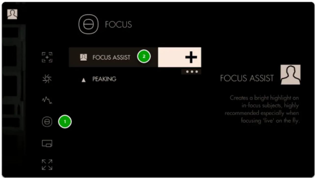
text_image
FOCUS FOCUS ASSIST 2 + ▲ PEAKING FOCUS ASSIST Creates a bright highlight on in-focus subjects, highly recommended especially when focusing 'live' on the fly.Focus Assist will paint a highlight around areas it determines to be in focus based on small/harsh changes in contrast.
The Peak Threshold is a bit high, meaning we are picking up extraneous edges on the back wall which are not quite in focus.
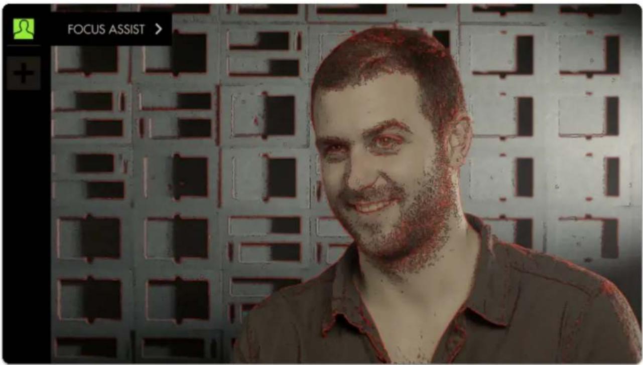
text_image
FOCUS ASSIST >To fix this, edit Focus Assist by pressing to the right when it is highlighted in the tool bar, and navigate to Peak Threshold.
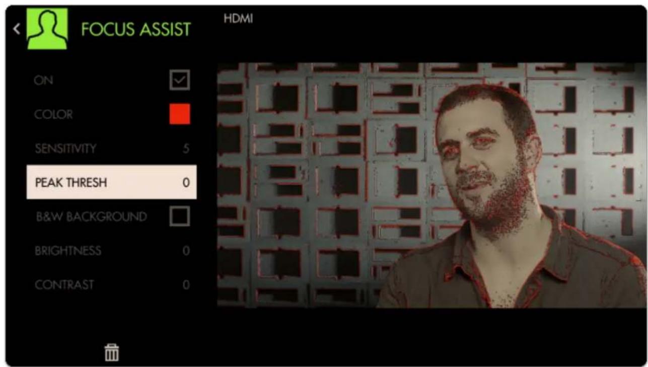
text_image
FOCUS ASSIST HDMI ON COLOR SENSITIVITY 5 PEAK THRESH 0 B&W BACKGROUND BRIGHTNESS 0 CONTRAST 0
SmallHD User Manual
Bringing Peak Threshold up to around 30 does a better job of causing only in-focus areas to activate the filter but this is ultimately a balance that may need tweaking depending on the camera/shot.
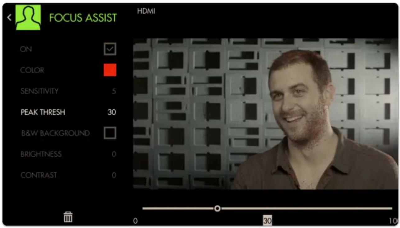
text_image
FOCUS ASSIST HDMI ON COLOR SENSITIVITY 5 PEAK THRESH 30 B&W BACKGROUND BRIGHTNESS 0 CONTRAST 0 0 30 10To make the effect more visible we can boost up the Sensitivity and change the Color.

Click here for an in-depth look at Focus Assist
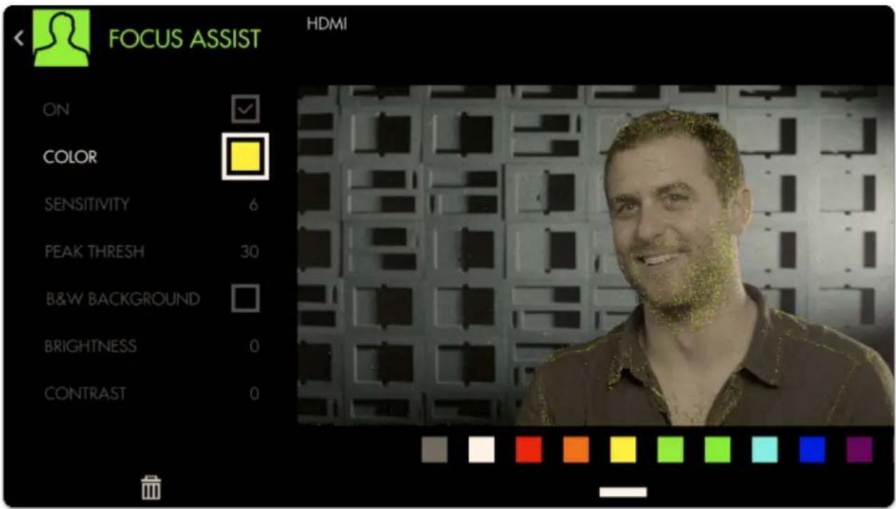
text_image
FOCUS ASSIST HDMI ON COLOR SENSITIVITY 6 PEAK THRESH 30 B&W BACKGROUND BRIGHTNESS 0 CONTRAST 0Next Add a Crosshair to the page by going through Add Tool > Frame > Crosshair
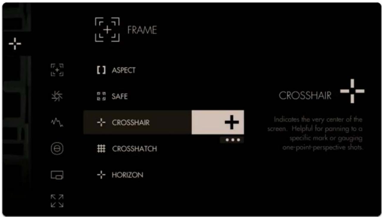
text_image
FRAME 【】 ASPECT SAFE CROSSHAIR CROSSHATCH HORIZON Indicates the very center of the screen. Helpful for panning to a specific mark or gauging one-point-perspective shots.Finally we can add an Aspect Guide by going to Add Tool > Frame > Aspect.
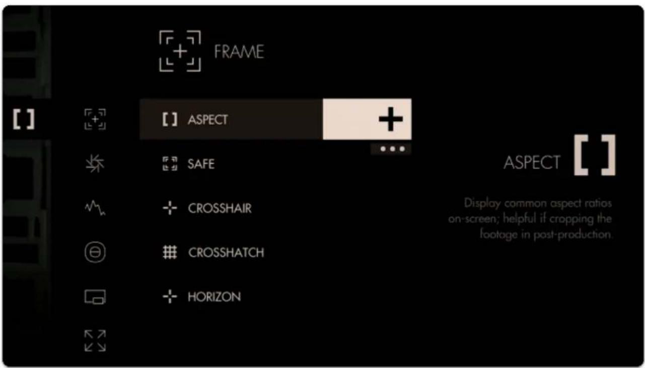
text_image
FRAME [ ] ASPECT + SAFE CROSSHAIR CROSSHATCH HORIZON ASPECT [ ] Display common aspect ratios on-screen; helpful if cropping the footage in post-production.This time when highlighting the '+', press down once and click to add Aspect Guides to all pages.
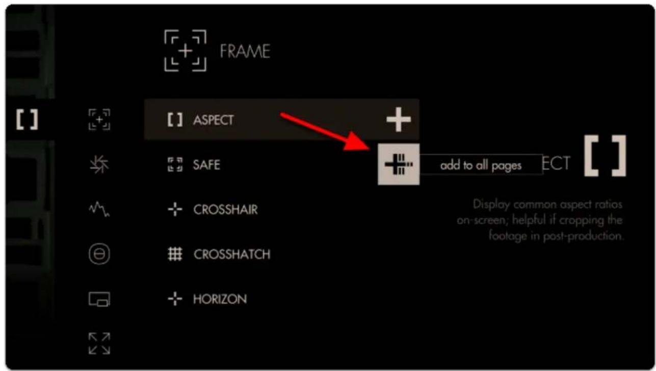
text_image
FRAME [ ] ASPECT + SAFE add to all pages ECT [ ] + CROSSHAIRCROSSHATCH
+ HORIZON Display common aspect ratios on-screen; helpful if cropping the footage in post-production.
SmallHD User Manual
This will ensure you are able to view this tool on every page of the monitor, and any edits to it are made globally. Any tool can be added to all pages, including scaling adjustments and Look (3D LUT) files.
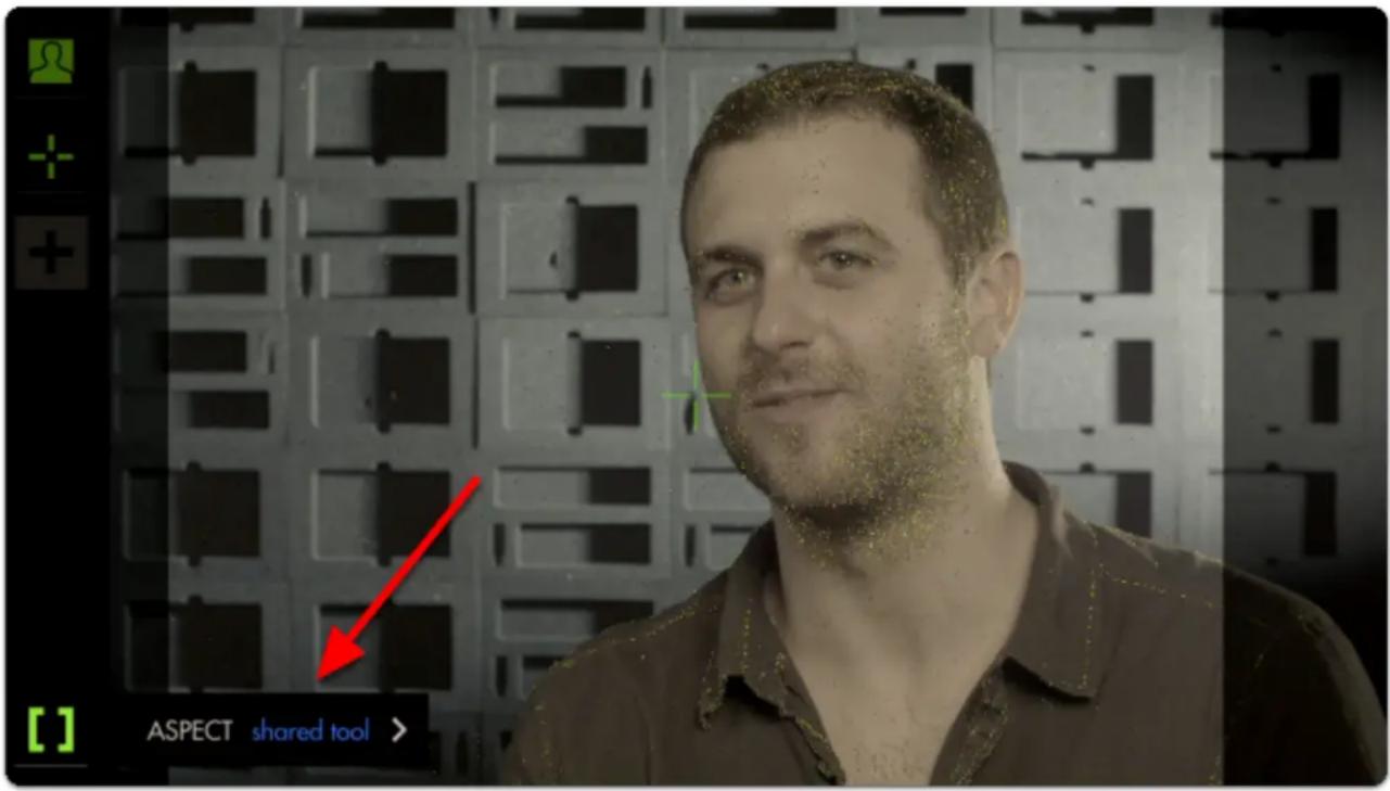
text_image
ASPECT shared tool >By default the Aspect Guide is set up for a 4x3 aspect ratio for times when you're needing to preview the cutoff area of an old-school monitor.
Press right to edit the Aspect Guide.
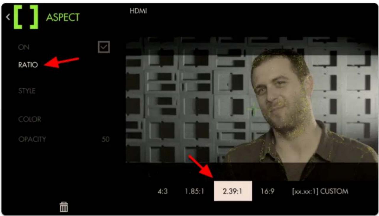
text_image
[ ] ASPECT HDMI ON RATIO STYLE COLOR OPACITY 50 4:3 1.85:1 2.39:1 16:9 [xx.xx:1] CUSTOMNavigate to "Ratio", select it and change the aspect ratio to "2.39" for cinemascope viewing.
Next move down to 'Opacity' and increase its percentage to view the guide becoming more opaque for a more visible effect.
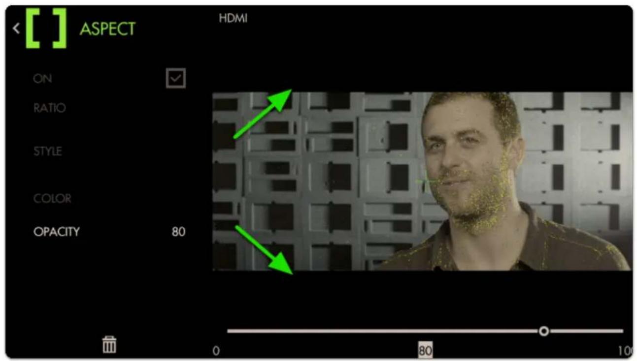
text_image
[ ] ASPECT HDMI ON RATIO STYLE COLOR OPACITY 80 0 80 10
Now we have a page that lets us focus our shot and frame it up properly for the common 2.39 aspect ratio.
Adding a Look (3D LUT) file to a page
Look files (3D LUTs) are a great way to visualize color grades without 'baking' anything into the footage - great for testing out different looks on set. Try our free 'Movie Looks' pack which can be placed on an SD card for use on your monitor or at any point in post production.
Let's add a Look to a new page - start by navigating back to the zoomed-out view, moving to the far right and selecting 'New Page' once more.
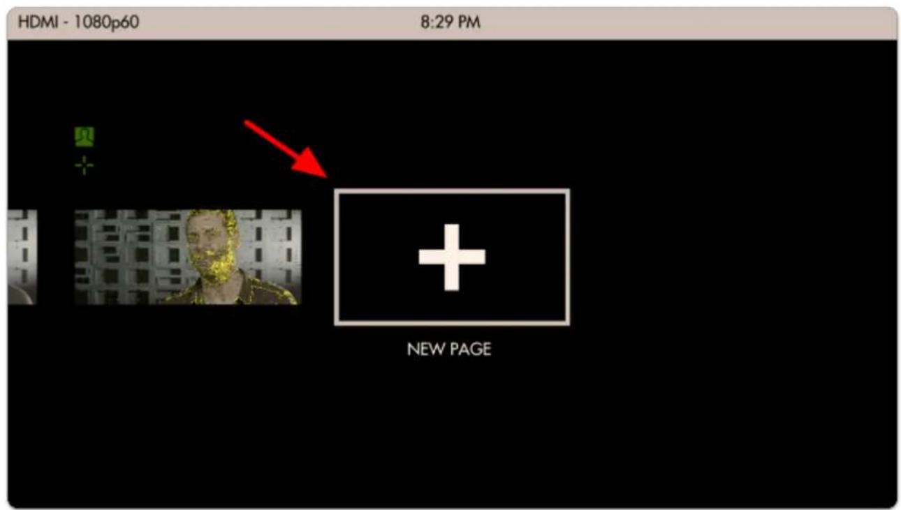
text_image
HDMI - 1080p60 8:29 PM NEW PAGENotice how when you add a new page, the Aspect Guide that was set for 'all pages' shows up automatically.
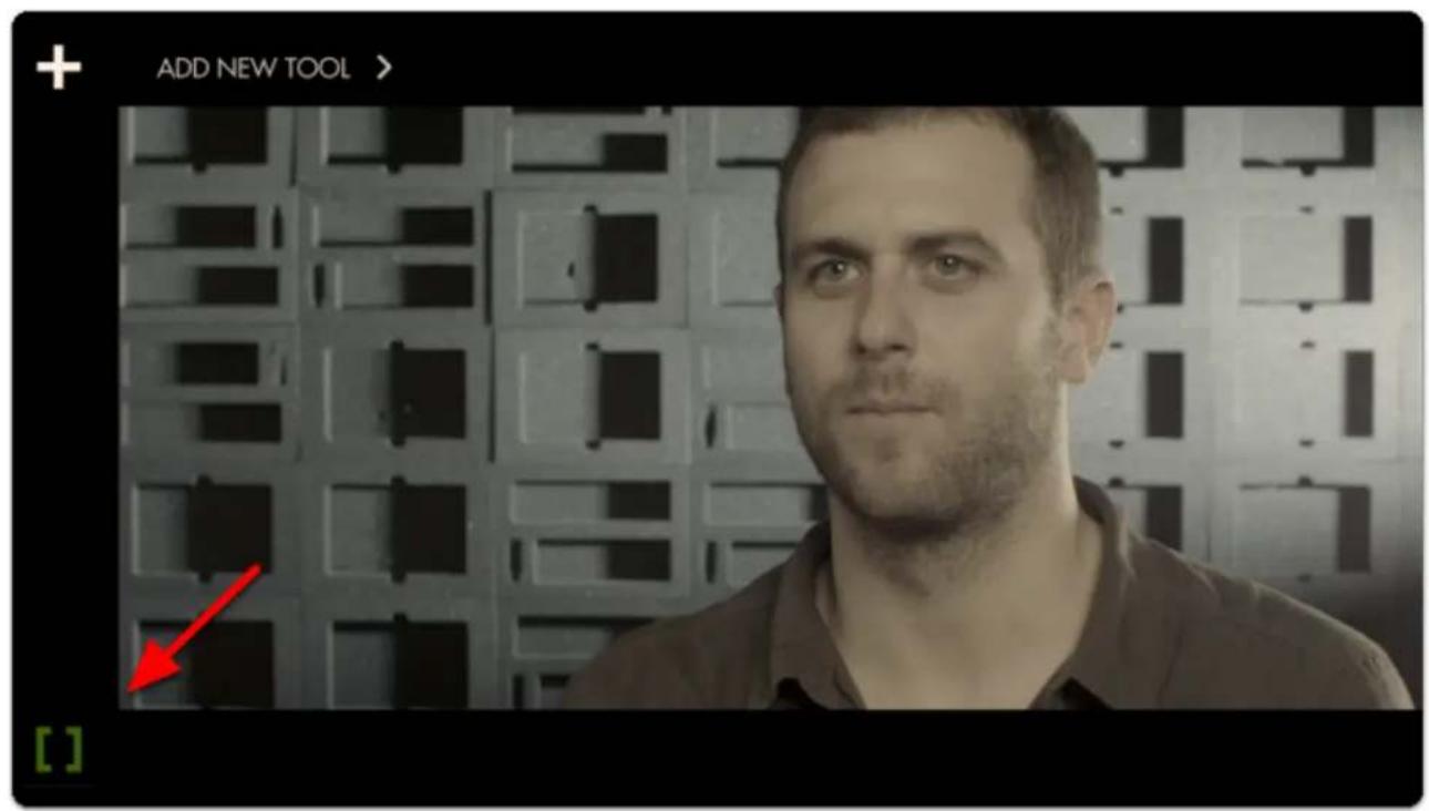
text_image
ADD NEW TOOL > [ ]
SmallHD User Manual
Click to add a new tool and this time navigate to Overlay > Look and select the '+'.
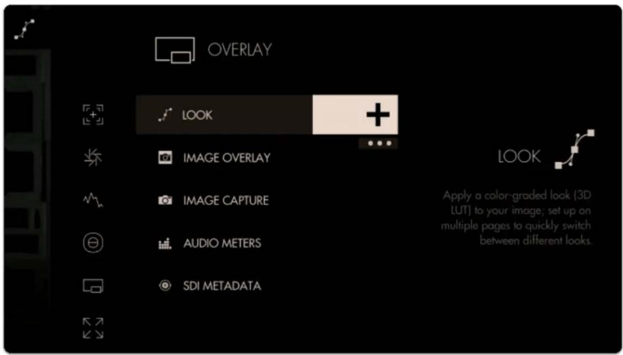
text_image
OVERLAY LOOK IMAGE OVERLAY IMAGE CAPTURE AUDIO METERS SDI METADATA Look Apply a color-graded look (3D LUT) to your image; set up on multiple pages to quickly switch between different looks.You will immediately be presented with a file browser to select a 3D LUT file.
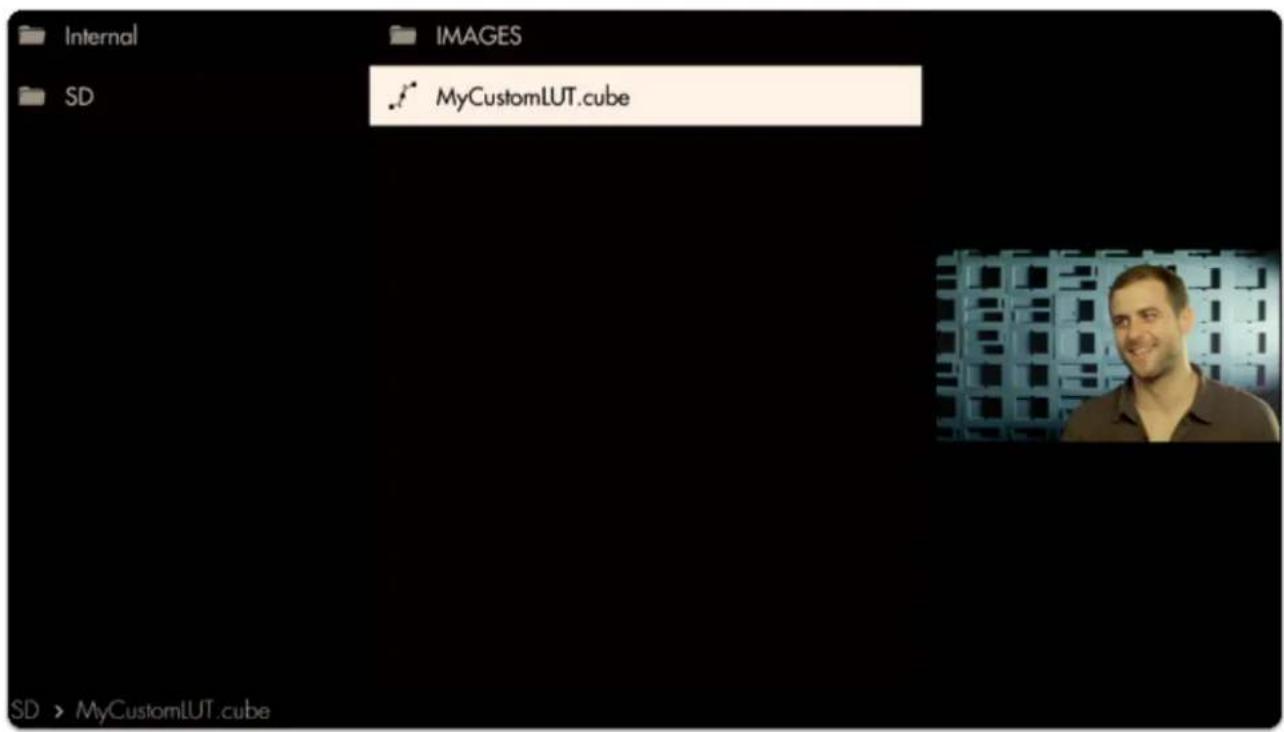
text_image
Internal IMAGES SD MyCustomLUT.cube SD > MyCustomLUT.cube
SmallHD User Manual
Selecting it will apply it to this page.
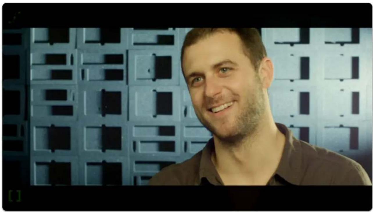
natural_image
Portrait of a smiling man with short hair and beard, standing in front of a patterned metal grid background (no text or symbols visible)
Adding several LUTs to several pages can be a great way to test out looks for a shoot while mobile, enabling creative decisions to be made early rather than in post production.
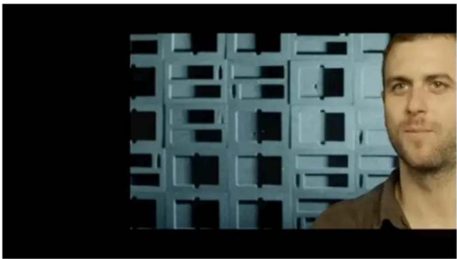
natural_image
Portrait of a man with short hair standing in front of a blue grid-patterned wall (no text or symbols visible)
To learn how to create your own color grade in Davinci Resolve and save the result as a LUT to be used on your monitor, check out the tutorial video (19m).
Conclusion
As you can see Pages can take very different roles depending on your needs. Don't be afraid to experiment to find the best setups!
Exposure - Case Study
Either before or after reading this guide you will have an understanding of how to set proper exposure using SmallHD's industry-leading toolset. Learn how Waveform, Exposure Assist, Zebra, Histogram and Color Picker compare and how to get the most from each.
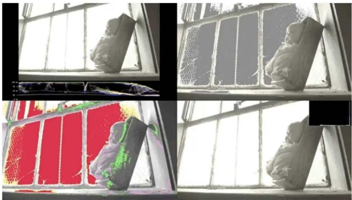
natural_image
Four-panel composite image showing a window with broken panels, a close-up of a textured surface, and a close-up of a person in a red shirt (no text or symbols visible)The Dynamic Range 'bucket'
Cameras have a limited dynamic range; this is the range between the darkest dark and the brightest bright a camera can simultaneously see and retain detail. If this range is set incorrectly, it can mean important details get lost or clipped.
The philosophy of the SmallHD toolset has always been to help free up the operator's mental burden - combined with pages, SmallHD's tools are designed to promote a level of confidence in the technical aspects of a shot to help free up creative energy. We haven't performed a formal study but we'd wager shooting with SmallHD monitors decreases stress on set.

SmallHD User Manual
Ambient lighting conditions change human perception of on-screen images so drastically that eyeballing the exposure range without aid can be highly risky; tools that present the range clearly are generally considered critical for consistent footage gathering.
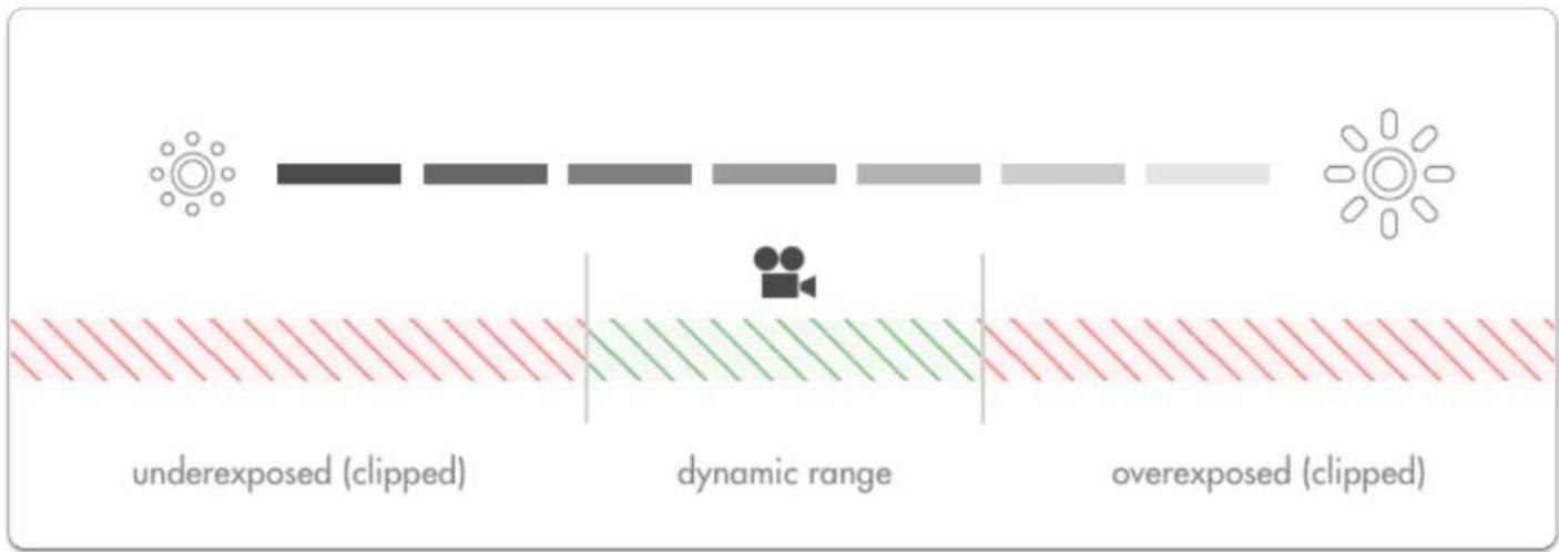
text_image
underexposed (clipped) dynamic range overexposed (clipped)Adjusting exposure will shift the dynamic range to capture brighter or darker detail in order to accommodate the most important aspects of the image. Anything outside the dynamic range gets clipped, meaning a badly placed exposure is wasting the camera's potential.
Exposure Examples
Let's look at the problems we face with a shot with a relatively low exposure (underexposed) and one with a relatively high exposure (overexposed).

natural_image
Silhouette of a person standing in front of a window with large windows and scattered debris (no text or symbols visible)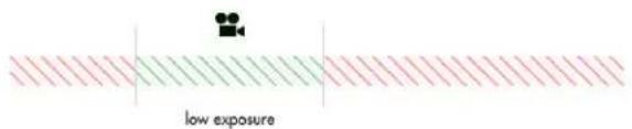
text_image
low exposure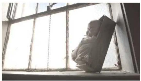
natural_image
Silhouette of a person sitting in a window with large windows, viewed from above (no text or symbols visible)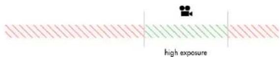
text_image
high exposureFor an easier direct comparison these shots have been color graded to roughly match one another:
natural_image
A child sitting on a wooden bench viewed through a window with large windows, no visible text or symbols.(Low exposure - brightened)
natural_image
Interior window with barred windows and a small wooden object on the left (no visible text or symbols)(High exposure - darkened)
natural_image
Two circular images: one showing a textured white surface, the other a close-up of a baby's face (no text or symbols visible)
natural_image
Two circular cropped images: one showing a red circular frame with small text, the other showing a close-up of a baby's face (no visible text or symbols)Underexposure --> Brightened Overexposure --> Darkened
| 1. Bright highlight detail remains in-tact (good) | 3. Bright highlights have been clipped, meaning the detail of the window cannot be recovered (bad) |
| 2. Shadow tones reveal noise when boosted (bad) | 4. The face of the doll is exposed well and contains minimal image noise (good) |

There will almost always be something in your image that is clipping like a dark shadow or a light bulb - the key is to be aware of and balance the extremes while ensuring the desired midtones (typically skin tones) are placed in the center of the camera's dynamic range.
Adjusting exposure
There are several ways to control exposure on a camera and it is critical when operating to have a firm grasp of the benefits and trade-offs of each. Let's have a look at them:
Scene lighting
If you have the benefit of a set with controllable lighting, the best scene exposure can be generally achieved without touching the camera. Because this is such a huge topic, we will just be covering adjustments that can be made on-camera.
Iris/Aperture
The most commonly used method for controlling exposure, the Iris or Aperture adjusts the physical size of the opening in the lens at which light passes through to reach the camera's imaging plane.

text_image
Aperture f22 f16 f8 f4 f2.8 f1.4 Brightness Depth of field ‘deep’ depth-of-field ‘shallow’ depth-of-field smalHDNotes on adjusting iris/aperture for exposure
Speed - Iris/Aperture is most often a physical ring on the lens, making it very quick to turn and immediately see a result.
Fine-tuned control - Higher-end & cinema lenses often have smooth or 'de-clicked' aperture rings making very precise exposure adjustments simple to achieve.
Affects depth of field - If part of the intended look of the scene is to have a character in focus with the background blurry, just be aware that adjusting the iris will affect the amount of blurriness (bokeh) in out-of-focus objects.
ISO
Increasing camera ISO essentially 'boosts' the camera's image digitally beyond its native ISO level, brightening the image but increasing the likelihood of image noise.
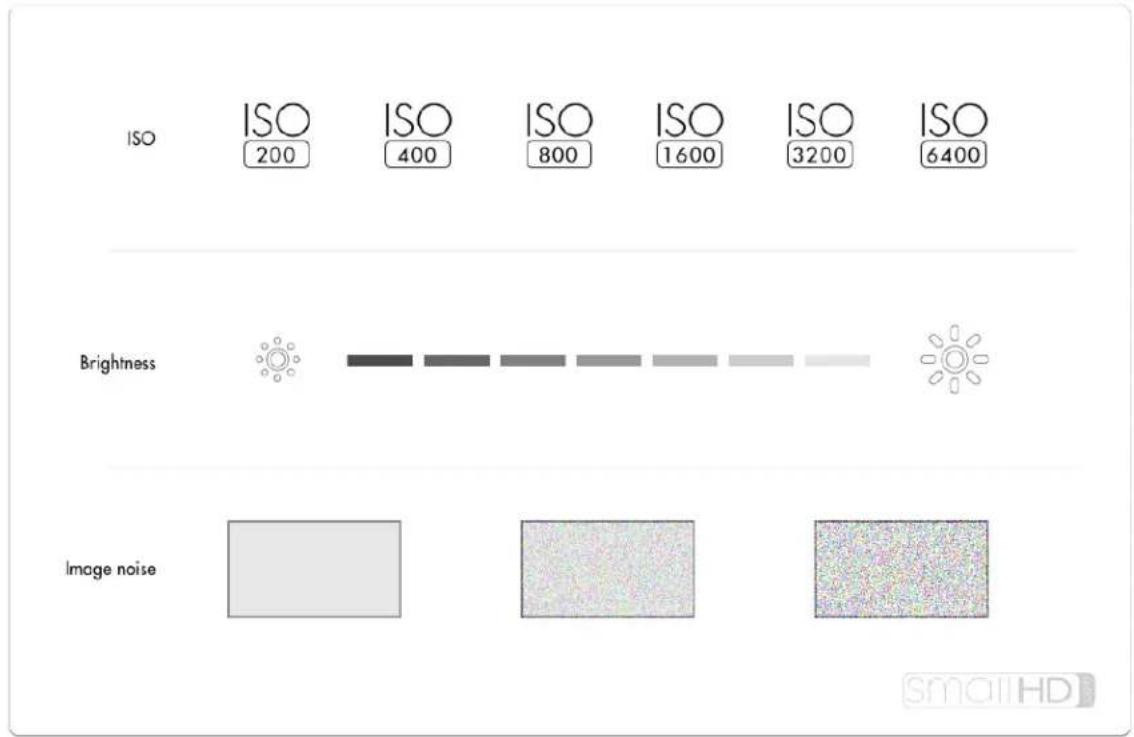
text_image
ISO ISO 200 ISO 400 ISO 800 ISO 1600 ISO 3200 ISO 6400 Brightness Image noiseNotes on adjusting ISO for exposure
Flexibility/Night Shooting - Some cameras have incredibly low-noise sensors and effective noise processing that can allow for high ISO values without noticeable artifacting meaning easier shooting in the dark. Mileage varies greatly and older cameras tend not to fare as well in this respect.
Notes on adjusting ISO for exposure
Variable Image Noise - Because adjusting ISO is artificially 'boosting' the output of the sensor, image noise, especially in shadows becomes more apparent at higher ISO values.

Every digital camera has a native ISO which tends to produce the least noisy results and the most dynamic range. Pushing the ISO up is asking the camera to reach further outside its 'comfort zone' and will increasingly apply image noise/lessen dynamic range.
Shutter Speed
Shutter speed refers to the amount of time the sensor is being exposed to light for each frame. Shutter speed is slightly less commonly used when adjusting exposure due to it having a more pronounced stylistic effect at different extremes.
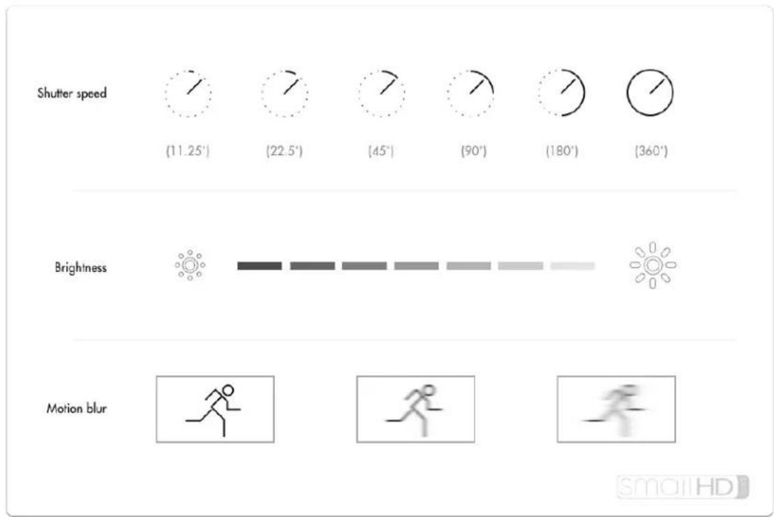
text_image
Shutter speed (11.25°) (22.5°) (45°) (90°) (180°) (360°) Brightness Motion blur smalHDNotes on adjusting shutter speed for exposure
Controls perceived 'smoothness' of motion - if footage motion appears too smooth for the intended
Notes on adjusting shutter speed for exposure
style, increasing shutter speed will increase a 'strobing' effect, think the 'Saving Private Ryan' look where action appears frozen in time.
Consistency of shots - If adjusting shutter speed for every shot to compensate for lighting, the amount of 'strobing' (ie perceived smoothness) will vary shot-to-shot as well and this may be displeasing to some viewers.

An extremely common & widely acceptable shutter speed setting is at half the frame rate being captured, commonly referred to as a 180^ shutter. If shooting at 24 frames per second, this means the shutter speed would be 1/48th of a second.
Lens Filters
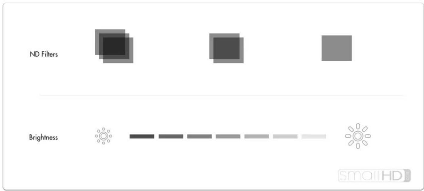
text_image
ND Filters Brightness smallHDLens filters offer creative flexibility on brightly lit scenes - instead of having to raise shutter speed and increase strobing, or close down the aperture and deepen the depth of field, ND (neutral density - aka darkening) filters can darken the shot without adjusting the aesthetic.
Notes on adjusting lens filtration for exposure
Shallow depth of field on bright days - dense ND (neutral density ie darkening) filters make shallow depth-of-field possible on very bright days - other options are to close down the iris (resulting in deep depth of field) or increasing shutter speed (resulting in stuttery motion).
Localized Adjustments - ND filters often have a graduated (dark to light) effect so that adjustments are made only to a portion of the image - great for dimming a bright sky while keeping a darker foreground in tact.
Speed of operation will vary - Many cameras have built-in ND filters which are speedy to operate but for cameras that dont, they will have to be threaded onto to a lens or slid into a matte box which can be slower options than rolling the iris/aperture.
Choosing an exposure tool
We have found personal preference to be the biggest factor when choosing an exposure tool. Wish to see exposure issues directly on the image as they happen? Exposure Assist or Zebra may be right for the job. Prefer an untouched image with a separate graph to provide value readings for spotting issues? Waveform or Histogram may suit your needs better.
Exposure Assist

EXPOSURE ASSIST
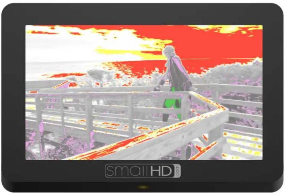
natural_image
Illustration of a person standing on a balcony overlooking a sunset sky with red and yellow hues (no text or symbols)Exposure Assist is a great overall balance of utility and ease of use and can benefit most shooting scenarios. It allows 'painting' the image depending on the intensity of a pixel's luma value. For example you could set 97% IRE and up to turn bright red as an overexposure warning while creating a scale to turn green when a face is exposed properly at 55%, etc. (& anything else you wish to plot to any points on the range). Click to learn more about Exposure Assist.

New firmware 3.0 feature - Exposure Assist scale is now fully customizable!
Zebra

ZEBRA
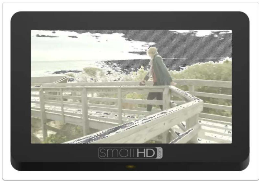
natural_image
Person walking on a wooden balcony overlooking a coastal landscape with ocean and trees (no visible text or symbols)Zebra is essentially a simplified version of Exposure Assist which allows the specific 'painting' of areas depending on brightness value but is less destructive to the underlying image -- it is however limited to painting one value range at a time, though up to two Zebra tools can be activated simultaneously. Click to learn more about the Zebra tool.
Waveform

text_image
WAVEFORM
text_image
smallHD comWaveform plots the value of the entire image onto a graph that physically matches it from left-to-right, meaning if you see an area that's too bright on the left side of the image, it will create a 'peak' on the left side of the waveform graph. It also has other benefits by way of RGB & RGB Parade modes. Click to learn more about the Waveform.

Use the Waveform to check evenness of lighting across a solid-color backdrop- just look for a straight line all the way across.
Histogram

text_image
HISTOGRAM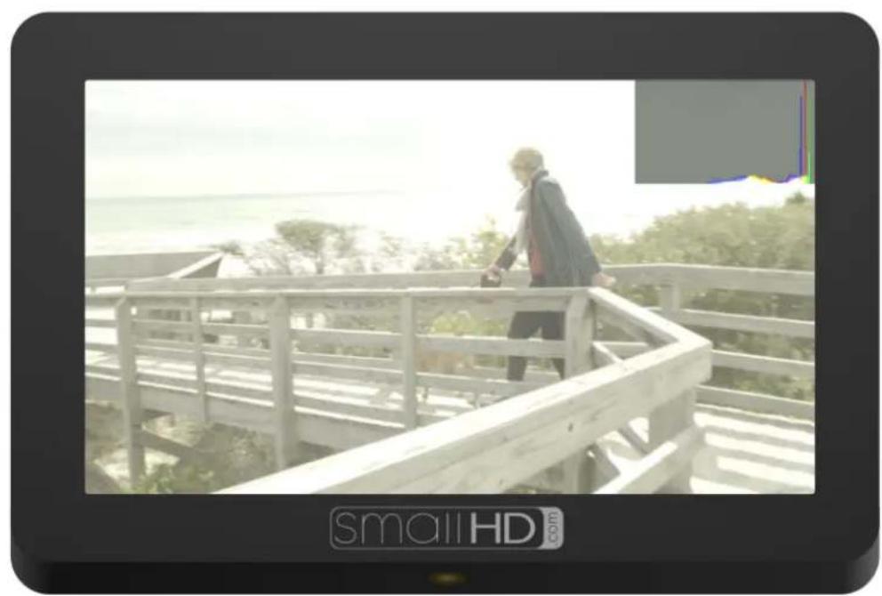
natural_image
Person walking on a wooden deck overlooking a coastal landscape with ocean and trees (no text or symbols visible)Histogram sorts every pixel in your image based on its brightness and plots it to a chart; darker values on the left and brighter values on the right. Click to learn more about the Histogram.

If you see that the Histogram is mostly a 'lump' towards the left hand side, you may have a generally under-exposed image (or a normally-exposed night scene). If it is stacked up towards the right, you may have an over-exposed image (or a normally-exposed day time snow scene).
Color Picker
Color Picker
Color Picker samples color/value information from a single pixel to give a precise readout of a specific location. Click to learn more about the Color Picker.

When you need an extra level of information on a very precise location, set up a color picker on your subject's face and as light levels change, roll exposure or relight to compensate to achieve the same or a similar readout.
Focusing Tips
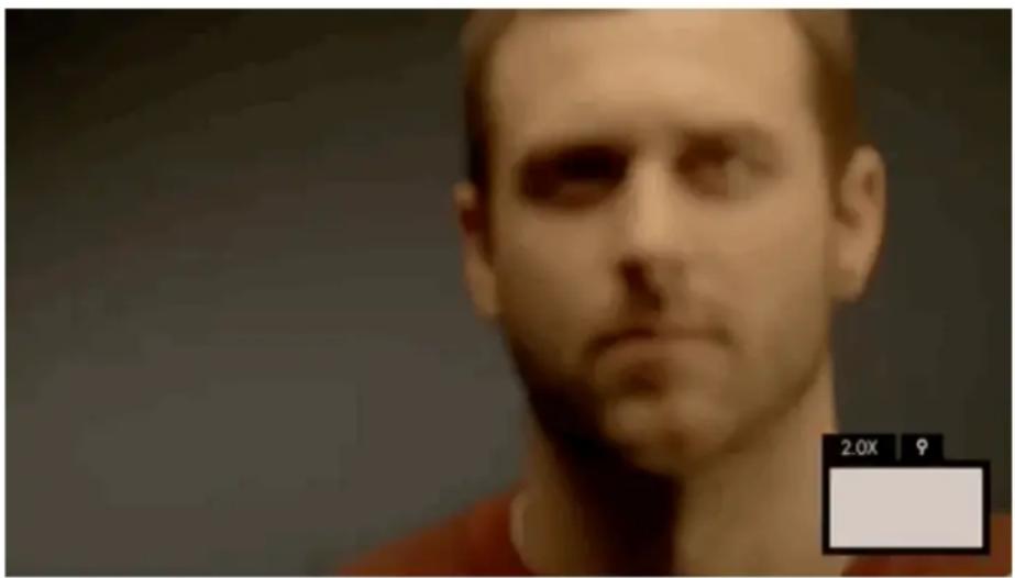
natural_image
Close-up portrait of a man with short hair and beard, wearing a red shirt (no visible text or symbols)Manually focusing a camera with accuracy can be difficult, thankless, and if unchecked can lead to a surprise of the worst kind in post-production. Use SmallHD's industry-leading focusing toolset to help achieve razor-sharp focus every time and to free you up for other on-set tasks.
Pixel Zoom

text_image
Pixel ZoomPixel Zoom lets you quickly 'push in' to your image to make careful judgements over any details and to check for accurate focus before rolling. Because you're seeing the actual image up close you can be extra confident making decisions using this tool.
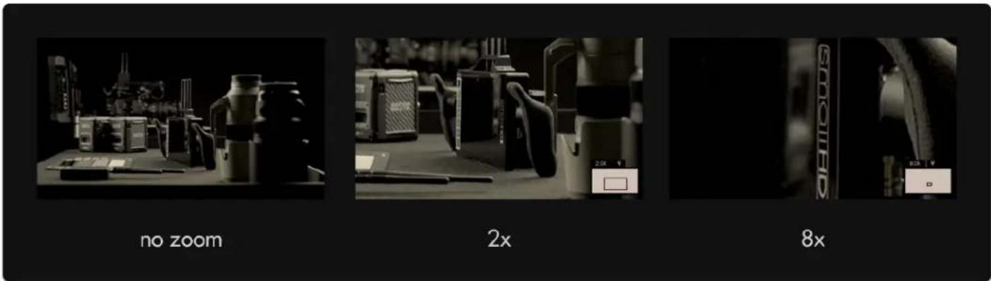
text_image
no zoom 2x 8x
Pixel zoom is unique in that it isn't added to a page like other tools but is accessible from any time by pushing up on the joystick or using pinch-to-zoom on touchscreen monitors.
Focus Assist
Focus Assist
Focus Assist is a filter that looks at your image for areas of dense contrast and highlights those areas with a color of your choosing. This represents the 'in-focus' portion of your image which can be seen clearly in a wide variety of viewing conditions.
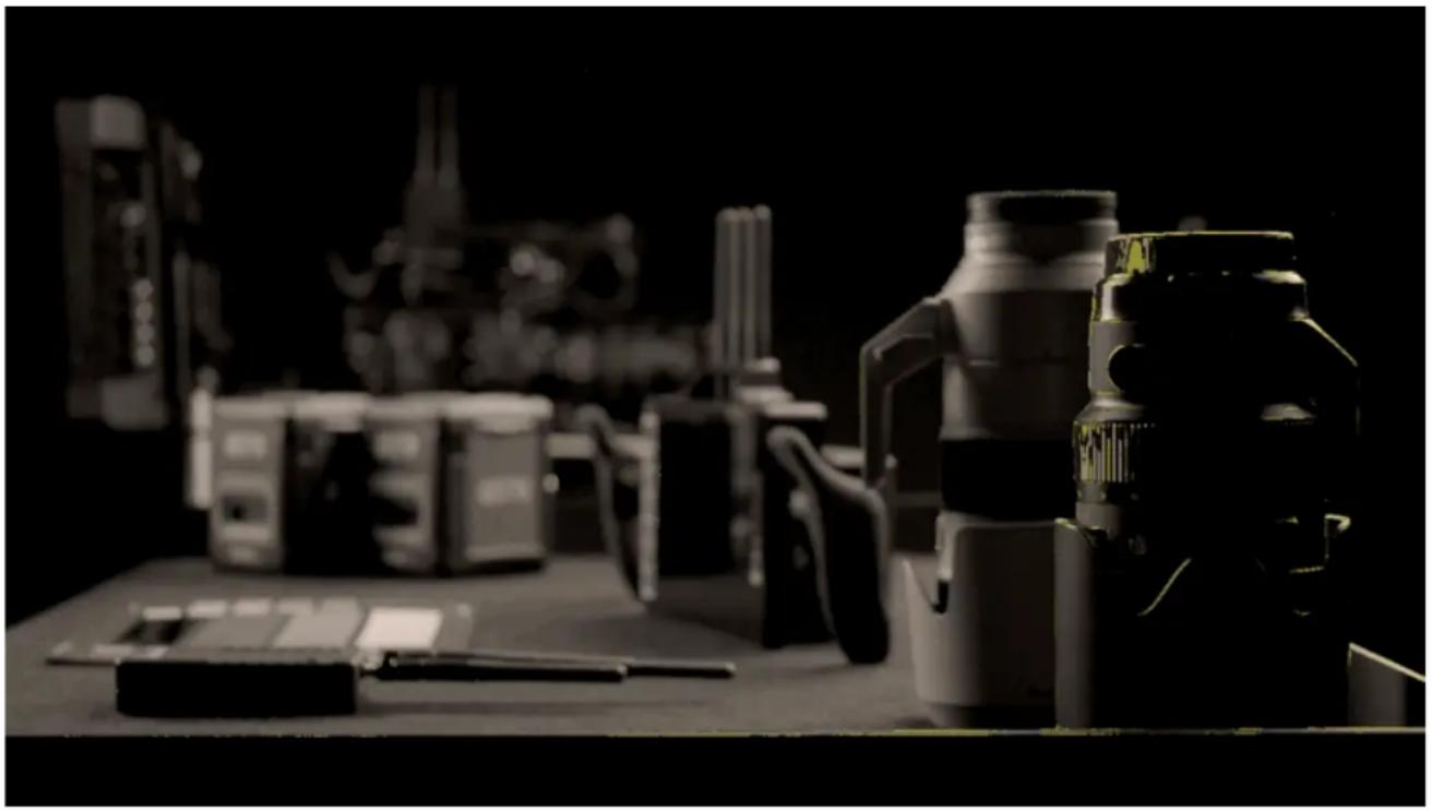
natural_image
Black-and-white photo of various electronic devices including thermos, batteries, and a camera on a desk (no visible text or symbols)
If you need the fastest, most apparent view of what's in focus, for example when shooting with a gimbal where you can't get a close view of the screen, Focus Assist is a great option.
Peaking

text_image
PeakingPeaking is essentially the 'sharpness' filter turned all the way up -- meaning in-focus edges highlight similarly to Focus Assist, but it doesn't alter the image as drastically which can be helpful when used in combination with other tools.
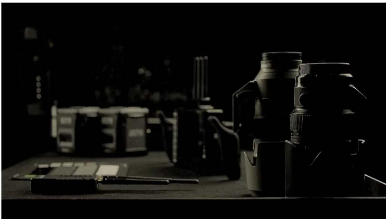
natural_image
Black-and-white photo of a professional setting with multiple cameras and a handheld device on a desk (no visible text or symbols)
If you need to manage several aspects of your image at once while still focusing, Peaking may be the correct tool for the job since it doesn't mess around too much with the integrity of the original image.