
Microline 420N - Printer OKI - Free user manual and instructions
Find the device manual for free Microline 420N OKI in PDF.


User questions about Microline 420N OKI
0 question about this device. Answer the ones you know or ask your own.
Ask a new question about this device
Download the instructions for your Printer in PDF format for free! Find your manual Microline 420N - OKI and take your electronic device back in hand. On this page are published all the documents necessary for the use of your device. Microline 420N by OKI.
USER MANUAL Microline 420N OKI
natural_image
Line drawing of a microarray printer with control panel and display screen (no text or symbols)Oki, Network Solutions
for a Global Society
59348301
ML 420/421 User's Guide
P/N 59348301, Revision 1.2
February, 2006
Every effort has been made to ensure that the information in this document is complete, accurate, and up-to-date. Oki Data assumes no responsibility for the results of errors beyond its control. Oki Data also cannot guarantee that changes in software and equipment made by other manufacturers and referred to in this guide will not affect the applicability of the information in it. Mention of software products manufactured by other companies does not necessarily constitute endorsement by Oki Data.
Copyright 2002, 2007 by Oki Data. All rights reserved.
Written and produced by the Oki Data Training and Publications Department.
Web Site: http://www.okiprintingsolutions.com.
Trademark Information
OKI and MICROLINE are registered trademarks of Oki Electric Industry Company, Ltd.
Epson is a registered trademark of Epson America, Inc. IBM is a registered trademark of International Business Machines Corp.
Microsoft and Windows are either registered trademarks or trademarks of Microsoft Corporation in the United States and other countries.
Safety
Your Oki printer has been carefully designed to give you years of safe, reliable performance. As with all electrical equipment, there are a few basic precautions you should take to avoid hurting yourself or damaging the printer:
- Carefully read all setup and operating instructions. Be sure to save all documents for future reference.
- Read and follow all warning and instruction labels on the printer itself.
- Place your printer on a firm, solid surface. If you put in on something unsteady, it might fall and be damaged.
- Avoid overheating the printer. Do not place it on a soft surface, such as a rug, sofa, or bed. The vents may be blocked, causing the printer to overheat.
-
The printer must be installed near a power outlet which will remain easily accessible.
-
Be certain that your power source matches the rating listed on the back of the printer. If you aren't sure, check with your dealer or with your local power company.
- Your printer has a grounded, 3-prong plug as a safety feature. It will only fit into a grounded outlet. If you can not plug it in, chances are that you have an older, non-grounded outlet. Contact an electrician to have it replaced with a grounded outlet. Do not use an adapter to defeat the grounding.
- To avoid damaging the power cord, do not put anything on it or place it where it will be walked on. If the cord becomes damaged or frayed, replace it immediately.
-
If you're using an extension cord or power strip with the printer, make sure that the total of the amperes required by all the equipment on the extension is less than the extension's rating. Generally, the total ratings of all equipment plugged into any one power line should not exceed 15 amperes. Don't exceed this unless you know that the power line your equipment is plugged into has a rating above 15 amperes.
-
Unplug the printer before you clean it. Use only a damp cloth. Do not use liquid or aerosol cleaners.
- To protect your printer from overheating, make sure no openings on the printer are blocked. Do not put the printer on or near a heat source, such as a radiator or heat register. If you put the printer in any kind of enclosure, make sure it is well ventilated.
- The printhead can get quite hot when it has been printing for a length of time. Do not touch the printhead until it has had a chance to cool off.
- Do not use your printer near water. Do not spill liquid of any kind into it.
- Do not poke anything into the ventilation slots on the sides of the printer. You could get a shock or cause a fire.
- Aside from the routine maintenance described in this document, don't try to service the printer yourself. Opening the cover may expose you to shocks or other hazards. Don't make any adjustments other than those outlined in the document. You might cause damage requiring extensive repair work.
- If anything happens that indicates that your printer is not working properly or has been damaged, unplug it immediately. Then, follow the procedures in “Service and Support” for having your printer serviced.
These are some of the things to look for:
– The power cord or plug is frayed or damaged.
– Liquid has been spilled into the housing, or the printer has been exposed to water.
- The printer has been dropped or its cabinet has been damaged.
- The printer doesn't function normally when you're following the operating instructions.
Contents
Safety.... 3
Chapter 1: Introduction ...... 7
Printer Features....7
Chapter 2: Helpful Hints .... 8
Saving Money: Forms Tear-Off....8
Saving Time....8
Internet Support 8
Paper Park 8
Operation Tips 9
Top of Form (TOF) 9
Turning the Platen Knob 9
Controlling Access to the Printer 9
Chapter 3: Using Your Printer .... 10
Parts Identification: Rear Feed (Continuous Forms).... 10
Parts Identification: Top Feed (Single Sheets) 11
Top of Form (TOF) 12
Top of Form (TOF) and Forms Tear-Off.... 12
Determining if Forms Tear-Off is Off or On.... 13
Setting Top of Form (TOF):
Forms Tear-Off OFF (Default Setting) 14
Setting Top of Form (TOF):
Forms Tear-Off Set to ON 15
Temporarily Changing the Top of Form Position 16
Resetting Top of Form to the Factory Default 16
Forms Tear-Off Feature 17
Potential Problems with Software Packages 17
Changing the Forms Tear-Off Setting 18
Manual Forms Tear Off.... 18
Paper Park....18
Changing Paper Paths.... 19
Printhead Gap 21
Print Quality 22
Character Pitch 23
Printer Reset 24
Emulations 24
Chapter 4: Menu Mode ...... 25
Menu Mode Keys.... 25
Entering and Exiting Menu Mode 26
Resetting the Menu to the Factory Defaults 26
Printing the Menu Settings.... 26
Changing the Menu Settings 27
Menu Settings Table.... 28
Explanations of Menu Items 35
Chapter 5: Maintenance.... 42
Replacing the Ribbon Cartridge 42
Loading Paper.... 44
Rear Feed 44
Top Feed (Single Sheets) 53
Clearing Paper Jams 55
Rear-Feed Paper Jams 55
Rear-Feed, Repeating Paper Jams.... 56
Single-Sheet Paper Jams 58
Cleaning the Housing 59
Chapter 6: Troubleshooting.... 60
General Information 60
Problems / Solutions 61
Appendix A: Parts & Accessories...... 66
Purchasing Parts & Accessories 66
Replacement Parts 67
Accessories 68
Appendix B: Printer Control Codes 69
IBM Proprinter III Commands 69
Epson FX Commands.... 72
Oki MICROLINE Standard Commands 75
Appendix C: Specifications.... 78
Appendix D: Installation.... 84
Location 84
Unpack....84
Install the Ribbon Cartridge 87
Power Connection 88
Computer Connections 88
Parallel (LPT): IEEE 1284 88
USB: Specification 1.1 Compliant....89
Loading Paper....89
Testing the Printer....90
Font Sample Test 90
Rolling ASCII Test 91
Hexadecimal Dump Mode 92
Emulations 92
Printer Drivers 92
Loading the OKI Driver 93
Using a Compatible Driver 93
Index 94
Chapter 1: Introduction
Printer Features
- Super reliable, durable operation: 20,000 hours Mean Time Between Failures (MTBF) at 25% duty cycle and 35% page density
- Advanced paper handling, with built-in rear push tractor and zero-tear forms capability.
- Blazing print speeds, in characters per second:
– High Speed Draft (HSD) Mode: 507 cps
- Utility Mode: 380 cps
– Near Letter Quality (NLQ) Mode: 95 cps
– Super Speed Draft (SSD) Mode: 570 cps
- This rugged 9-pin printer can meet the needs of harsh and demanding environments.
Oki Data on the Internet
The Oki Data Web Sites provide the most current information available on your printer.
On-line documents are available for viewing and downloading via Oki Data's Web Sites.
You may reach Oki Data via the Internet at:
- www.okidata.com
- my.okidata.com
Chapter 2: Helpful Hints
Saving Money: Forms Tear-Off
The Forms Tear-Off feature allows a printed continuous forms page to be torn off without wasting paper or adjusting the printer.
When printing stops, Forms Tear-Off automatically moves the paper to align the perforation with the tear bar (located under the access cover), after a time interval which you select through the menu.
Paper remains in the tear-off position until the printer receives more data. Then, the paper moves back down for printing.
Note: This feature is normally turned off.
Important!
Forms Tear-Off and the Top of Form settings interact. For more information, see “Top of Form (TOF) and Forms Tear-Off” in Chapter 3.
Saving Time
Internet Support
Oki Data provides support via the Internet:
- www.okidata.com is the main web site, the gateway to Oki Data's products and services.
- http://my.okidata.com is a powerful area of Oki Data's web site designed to help you personalize the information and service you get from Oki Data.
Paper Park
Your printer's paper park feature allows you to print a single sheet (cut-sheet) page without removing continuous feed paper from the printer.
For more information, see "Paper Park" in Chapter 3.
Operation Tips
Top of Form (TOF)
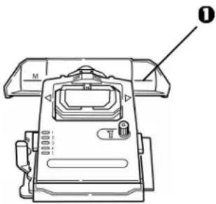
Top of Form (TOF) sets the print start position. The factory default is 1" from the top.
The Top of Form can be changed in increments of 1/180", either for a single print job or set to a new default. The overall amount of adjustment is limited to avoid paper jams.
The first line prints at the red line of the plastic paper shield (1) on the printhead.
text_image
Technical diagram of a mechanical device with labeled parts and numbered componentFor more information, see “Top of Form (TOF)” in Chapter 3.
Turning the Platen Knob
Important!
Always turn the printer off before turning the platen knob! If you turn the platen knob when the printer is on, the Top of Form misaligns.
Controlling Access to the Printer
You can control access to the printer by changing the setting for the Operator Panel Function in the Menu from Full Operation (the factory default) to Limited Operation.
When Limited Operation is selected, the PRINT QUALITY and CHARACTER PITCH keys don't work. This prevents these settings from being changed from the control panel when several people are using the printer.
For more information, see “Changing the Menu Settings” in Chapter 3.
Chapter 3: Using Your Printer
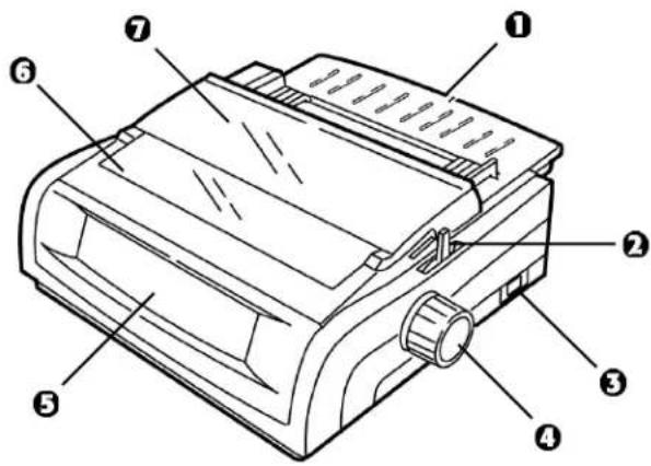
Parts Identification: Rear Feed (Continuous Forms)
Note: The serial number of your printer is on a label on the back, beside "S/N."
① Sheet Guide
② Paper Lever
③ On-Off Switch
4 Platen Knob
⑤ Control Panel
⑥ Acoustic Cover
⑦ Access Cover
Note: For rear feed, the paper lever must be forward.
text_image
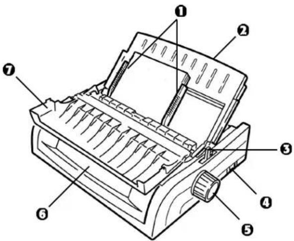
Technical diagram of a mechanical device with numbered parts labeled 1 through 7Parts Identification: Top Feed (Single Sheets)
① Paper Guides
② Sheet Guide
③ Paper Lever
④ On-Off Switch
⑤ Platen Knob
⑥ Control Panel
⑦ Acoustic Cover (open)
Note: For single-sheet printing, the paper lever must be in the middle position.
text_image
Technical diagram of a printer with numbered parts labeled 1 through 7Using Your Printer 11
Top of Form (TOF)
Important!
If you turn the platen knob when the printer is on, the Top of Form misaligns. Always shut the printer off before turning the platen knob!
Note: The factory default setting for the Top of Form (where the printing should begin) is 1" down from the top of the page.
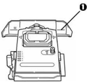
Top of Form sets the print start position for the printer. It is adjustable in increments of 1/144 of an inch. The amount of adjustment is limited to avoid paper jams.
The first line prints at the red line of the plastic paper shield (1) on the printhead.
natural_image
Technical line drawing of a mechanical device with labeled parts (no readable text or symbols)12 Microline 420/421 User's Guide
Top of Form (TOF) and Forms Tear-Off
Note: Your software may print the first line of print above or below where TOF is set. You may need to adjust the TOF to meet your software's requirements.
The Top of Form and Forms Tear-Off settings of your printer interact. How you set the Top of Form depends on whether Forms Tear-Off is On (set to 500 ms, 1 sec, or 2 sec) or OFF (the factory default setting).
Determining if Forms Tear-Off is Off or On
There are two ways to determine the status of the Forms Tear-Off menu setting:
- Print the Menu.
- Use the TEAR key.
flowchart
graph LR
    A["1 SEL"] --> B["2 SEL MENU"]
    B --> C["3 LF Micro Feed Down"]
    C --> D["4 TEAR"]
    D --> E["5 PARK"]
    E --> F["6 QUIET TOF"]

    subgraph EXIT POWER
        B --> G["EXIT POWER"]
        H["ALARM"] --> I["ALARM"]
        J["GROUP"] --> K["GROUP"]
        L["ITEM"] --> M["ITEM"]
        N["SET"] --> O["SET"]
        P["PRINT"] --> Q["PRINT"]
    end
To print the Menu:
1 Make sure paper is loaded.
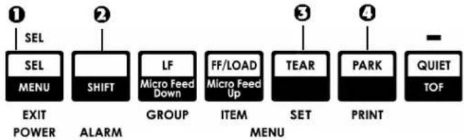
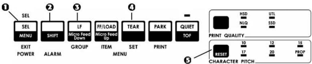
2 Hold SHIFT (2), then press SEL (1) to enter the Menu Mode.
3 Press PARK (4) to print the menu.
4 Look for the Form Tear-Off setting in the paper feed group you are using (Rear Feed, Bottom Feed or Top Feed—Forms Tear-Off appears in the Top Feed group only if the optional Roll Paper Stand is installed).
To use the TEAR key:
1 Make sure paper is loaded.
2 Press TEAR (3).
- If the paper moves up, Forms Tear-off is off.
- If the paper moves down, Forms Tear-off is on.
Setting Top of Form (TOF): Forms Tear-Off OFF (Default Setting)
Important!
If you turn the platen knob when the printer is on, the Top of Form misaligns. Always turn the printer off before turning the platen knob!
flowchart
graph TD
    A["① SEL"] --> B["② SEL MENU"]
    B --> C["③ LF Micro Feed Down"]
    C --> D["④ FF/LOAD Micro Feed Up"]
    D --> E["⑤ TEAR"]
    E --> F["⑥ PARK"]
    F --> G["⑦ QUIET TOF"]
    style A fill:#000,stroke:#000,color:#fff
    style B fill:#000,stroke:#000,color:#fff
    style C fill:#000,stroke:#000,color:#fff
    style D fill:#000,stroke:#000,color:#fff
    style E fill:#000,stroke:#000,color:#fff
    style F fill:#000,stroke:#000,color:#fff
    style G fill:#000,stroke:#000,color:#fff
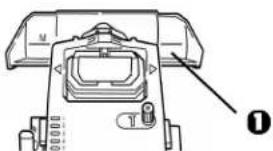
Note: The first line prints at the red line (1) of the plastic paper shield on the printhead.
text_image
Technical diagram of a mechanical device with labeled parts and an arrow pointing to component 014 Microline 420/421 User's Guide
With paper loaded and the printer on and selected:
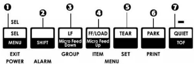
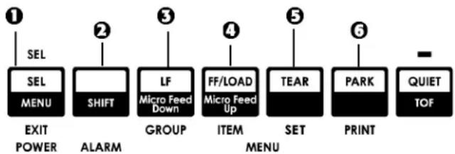
1 Press SEL | MENU (1) to take the printer off line. The SEL light goes out.
2 Press and hold SHIFT (2), then
Note: When you begin pressing the Micro Feed key, the printhead will move to the right.
- Press LF | Micro Feed Down (3) to set the TOF higher (the paper moves down).
- Press FF/LOAD | Micro Feed Up (4) to set the TOF lower (the paper moves up).
3 When you have the TOF set where you want it, press and hold SHIFT (2), then press QUIET/TOF (7) to engage the new setting. The printhead moves back to the left margin.
4 Press SEL/MENU (1) to save the setting and place the printer back on line.
Note: To reset the Top of Form to the factory default, see "Resetting Top of Form to the Factory Default" later in this chapter.
Setting Top of Form (TOF): Forms Tear-Off Set to ON
Important!
If you turn the platen knob when the printer is on, the Top of Form misaligns. Always turn the printer off before turning the platen knob!
flowchart
graph TD
    A["① SEL"] --> B["SEL MENU"]
    B --> C["EXIT POWER"]
    D["② SHIFT"] --> E["GROUP"]
    F["③ LF"] --> G["ITEM"]
    H["④ FF/LOAD"] --> I["MENU"]
    J["⑤ TEAR"] --> K["SET"]
    L["⑥ PARK"] --> M["PRINT"]
    N["⑦ QUIET TOF"] --> O["OUTPUT"]
Note: The first line prints at the red line (1) of the plastic paper shield on the printhead.
natural_image
Technical diagram of a mechanical component with labeled parts (no readable text or symbols)With paper loaded and the printer on and selected:
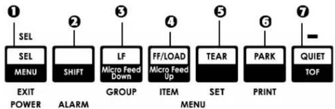
1 Press PARK (6) to park the paper.
The SEL light goes off and the red alarm light comes on.
2 Press SHIFT (2) and QUIET/TOF (7) to reset the current TOF.
3 Press FF/LOAD (4) to load the paper.
4 Wait briefly until the paper moves up to the tear position, then press and hold TEAR (5). The paper moves to the current TOF.
5 Keep holding TEAR, then press and hold SHIFT (2) and release TEAR.
6 Continue to hold SHIFT, then
Note: When you begin pressing the Micro Feed key, the printhead will move to the right.
- Press LF | Micro Feed Down (3) to set the TOF higher (the paper moves down).
- Press FF/LOAD | Micro Feed Up (4) to set the TOF lower (the paper moves up).
7 When you have the TOF set where you want it, press and hold SHIFT (2), then press QUIET/TOF (7) to engage the new setting. The printhead moves back to the left margin.
8 Press SEL/MENU (1) to save the setting and place the printer back on line.
Note: To reset the Top of Form to the factory default, see the next page.
Temporarily Changing the Top of Form Position
Important
Do not use the platen knob to change the Top of Form. If you turn the platen knob when the printer is turned on, the Top of Form misaligns. Always turn the printer off before turning the platen knob!
To move the Top of Form position lower for one page only:
1 Press SEL to deselect the printer.
2 Press LF to lower the position of the Top of Form.
Resetting Top of Form to the Factory Default
The factory default setting for the Top of Form (where the printing should begin) is 1" down from the top of the page.
To reset the Top of Form to the factory default:
1 Remove paper from the paper path.
2 Turn the printer off.
3 Press and hold PARK + QUIET/TOF while turning on the printer.
4 Reload paper.
Forms Tear-Off Feature
Note: This feature is normally turned off. To use Forms Tear-Off, you must enter the menu and change the setting to the desired time interval (see next page).
The Forms Tear-Off feature allows a printed continuous forms page to be torn off without wasting paper or adjusting the printer. It can be used for rear feed continuous forms, bottom feed continuous forms (with the optional push tractor installed) or for top feed roll paper (with optional roll paper stand installed).
When the printer is turned on, the paper feeds to the tear-off position.
When data is received, the paper automatically moves down to the print position (TOF) and printing begins.
Note: You can also move the paper down to the print position manually by pressing TEAR.
When printing stops, Forms Tear-Off automatically moves the paper to align the perforation with the tear bar (located under the access cover), after the time interval which you selected through the menu.
Paper remains in the tear-off position until the printer receives more data. Then, the paper moves back down for printing.
Notes: The status of the Forms Tear-Off menu setting affects how you set the Top of Form: see “Top of Form (TOF) and Forms Tear-Off” earlier in this chapter.
Do not use Forms Tear-Off with labels or multipart forms!
Forms Tear-Off cannot be used when the optional pull tractor is engaged.
Potential Problems with Software Packages
If Forms Tear-Off is set to On and the software package you are using “pauses” for a long enough interval while sending data to the printer, Forms Tear-Off may be activated. No data is lost, but this causes uneven print registration due to the paper movement.
If this occurs, use the menu to turn off this feature, then use the TEAR key to move the paper up to the tear position manually (see next page).
Changing the Forms Tear-Off Setting
Note: The default setting for Forms Tear-Off is OFF.
flowchart
graph LR
    A["① SEL"] --> B["SEL MENU"]
    B --> C["EXIT POWER"]
    D["② SHIFT"] --> E["ALARM"]
    E --> F["GROUP"]
    G["③ LF"] --> H["Micro Feed Down"]
    I["④ FF/LOAD"] --> J["Micro Feed Up"]
    K["⑤ TEAR"] --> L["ITEM MENU"]
    M["⑥ PARK"] --> N["PRINT"]
    O["QUIET TOF"] --> P["-"]
To change the Forms Tear-Off setting:
1 Press SHIFT (2) + SEL (1).
2 Press GROUP (3) repeatedly until the Rear Feed or Bottom Feed group shows in the first column of the printed line, depending on which paper feed you are using,
3 Press ITEM (4) repeatedly until Form Tear-Off appears in the second column:
Rear Feed Form Tear-Off Off
4 Press SET (5) until the time interval you wish to select appears in the third column:
Rear Feed Form Tear-Off 1 Sec
5 Press SHIFT (2) + SEL (1) to exit Menu Mode and save the setting.
18 Microline 420/421 User's Guide
Manual Forms Tear Off
If you don't wish to engage the Forms Tear-Off feature, you can advance
- rear-feed continuous forms loaded on the built-in tractor or
- bottom-feed continuous forms loaded on the optional push tractor
up to the tear off position manually by pressing TEAR (5).
Paper Park
Important!
Never park labels!
Paper park allows you to switch to single-sheet printing without removing continuous feed paper from the printer.
When you wish to print single sheets, simply press PARK (6) to retract the continuous form paper from the paper path, then lift the sheet guide, load the sheet and send the print job.
Changing Paper Paths
Continuous Forms to Single Sheets
1 Tear off any printed pages, then press PARK.
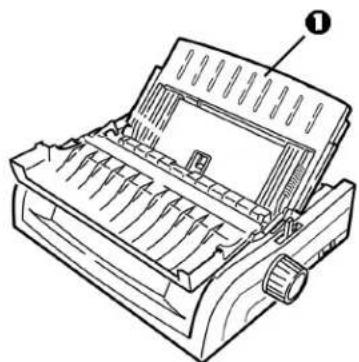
2 Raise the sheet guide (1) to the single-sheet feed position.
natural_image
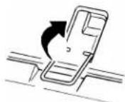
Line drawing of a printer with a paper feeding mechanism (no text or symbols)3 Pivot the wire feed guide into the sheet guide.
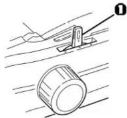
4 Move the paper lever (1) to the middle position marked "TOP."
natural_image
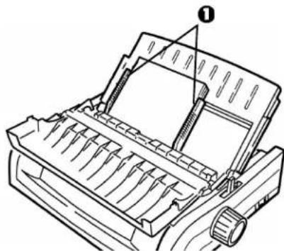
Technical line drawing of a mechanical component with a cylindrical part and a lever, no text or symbols present5 Adjust the paper guides (1) for the size paper you are using, then place a sheet of paper in the sheet guide.
natural_image
Technical line drawing of a mechanical device with internal components and a numbered label (no text or symbols present)Single Sheets to Continuous Forms
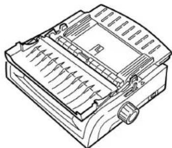
1 Press FF/LOAD to remove the single-sheet paper.
2 Lower the sheet guide into the continuous-forms position.
natural_image
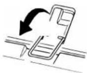
Line drawing of a mechanical device with internal blades and mounting features (no text or symbols)3 Swing the wire feed guide over onto the pull-up roller.
4 Move the paper lever to the appropriate position.
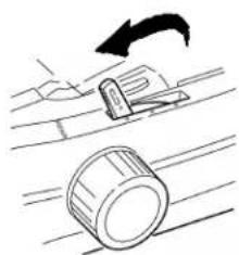
- Rear feed:
natural_image
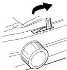
Diagram showing a mechanical device moving on a surface with an arrow indicating motion (no text or symbols)- Bottom feed:
natural_image
Diagram showing a hand moving a tool with an arrow indicating rotation, and a cylindrical object below (no text or symbols)5 If necessary, load continuous-form paper.
6 Press FF/LOAD.
Printhead Gap
The printhead gap is the distance between the printhead and the platen.
CAUTION!
Make sure the printer is turned off before you open the access cover.
To adjust the gap, open the access cover and move the blue lever (1) to the recommended setting from the table.

natural_image
Technical line drawing of a mechanical device with no visible text or symbolsSetting Media
| 1 Regular paper |
| 2 2-part form (with carbon) |
| 3 3-part form (with carbon) |
| 4 4-part form (with carbon) |
| 5 Envelopes or extra thick paper |
Note: When the head gap is set to 2, 3, 4 or 5, the printer automatically slows down for better print quality with multipart forms.
Print Quality
Important!
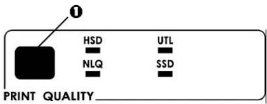
Front panel settings for print quality and character pitch are normally overridden by software commands.
text_image
PRINT QUALITY HSD NLQ UTL SSDPress PRINT QUALITY (1) to select:
UTL: Utility—the default
• Medium quality, medium speed (380 cps)
- Gothic typeface only
HSD: High Speed Draft
- Lower quality, higher speed (507 cps)
- Gothic typeface only
SSD: Super Speed Draft
- Lowest quality, highest speed (570 cps)
- Gothic typeface only
NLQ: Near Letter Quality
• Highest quality, slowest speed (95 cps)
- Courier or Gothic
Character Pitch
Important!
Front panel settings for character pitch are normally overridden when the SI command is received from your software.
text_image
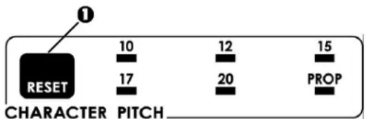
① RESET 10 12 15 17 20 PROP CHARACTER PITCHCharacter pitch determines how many characters will print on each line. You can choose a specific fixed width for each character in characters per inch (CPI), or Proportional. The higher cpi settings are often used for spreadsheets.
Proportional (PROP) sets character widths based on the character itself: e.g., the letter i is assigned a narrower width than the letter m. This provides a more polished, typeset appearance.
Note: To reset the printer to the factory default character pitch, deselect the printer, then press and hold the SHIFT key while pressing the CHARACTER PITCH key.
Epson and IBM Emulations
Set the character pitch by pressing CHARACTER PITCH (1) until the light beneath the desired setting is lit:
• 10 cpi
• 12 cpi
• 15 cpi
• 17 cpi
• 20 cpi
- Proportional
MICROLINE Emulation
In the MICROLINE emulation, the Character Pitch choices are:
• 10 cpi, Proportional or non-proportional
• 12 cpi, Proportional or non-proportional
• 15 cpi, Proportional or non-proportional
• 17 cpi, Proportional or non-proportional
• 20 cpi, Proportional or non-proportional
To select Proportional, press the CHARACTER PITCH key until both the cpi value and PROP lights are lit.
To select non-proportional, press the CHARACTER PITCH key until the light for the cpi value you wish to use is lit.
flowchart
graph LR
    A["① SEL"] --> B["② SEL MENU"]
    B --> C["③ LF"]
    C --> D["④ FF/LOAD"]
    D --> E["⑤ RESET"]

    subgraph Control Panel
        F["PRINT QUALITY"] --> G["HSD"]
        F --> H["UTL"]
        F --> I["NLQ"]
        F --> J["SSD"]
        G --> K["10"]
        H --> L["12"]
        J --> M["15"]
        K --> N["17"]
        L --> O["20"]
        M --> P["PROP"]
    end

    subgraph System Details
        Q["EXIT POWER"] --> R["ALARM"]
        S["GROUP"] --> T["ITEM"]
        U["SET"] --> V["PARK"]
        W["PRINT"] --> X["QUIET TOF"]
    end
Printer Reset
Clearing some error conditions requires that you reset (reinitialize) the printer. To do this:
1 Press and release SEL (1) to take the printer off-line. The SEL light goes out.
2 Press and hold SHIFT (2), then press the RESET/CHARACTER PITCH key.
Important!
Pressing SHIFT + RESET reinitializes the printer, but does not affect any menu settings and does not reset the printer to the factory defaults. For information on resetting the printer to the factory defaults, see “Resetting the Menu to the Factory Defaults” later in this chapter.
Emulations
- IBM ^ Proprinter III — factory setting
- Epson ^® FX
- Oki ^® MICROLINE ^®
Changing Emulations
1 Make sure paper is loaded.
2 Press and hold SHIFT (2), then press SEL (1).
3 Press LF (3).
The following line prints:
Printer Control Emulation Mode IBM PPR
4 Press TEAR (4) repeatedly until the emulation you wish to select prints in the right-hand column.
5 Press and hold SHIFT (2), then press SEL (1) to save your setting and exit the Menu Mode.
Chapter 4: Menu Mode
Note: Please print the current Menu Mode settings before you reset or change them. This is the only way to have a record of the settings.
In Menu Mode, you use the front panel keys to change the defaults for the printer parameters. The changes you make in the Menu Mode are automatically saved when you exit the Menu Mode and are retained, even when you turn the printer off.
Menu Mode Keys
flowchart
graph LR
    A["SEL"] --> B["MENU"]
    B --> C["EXIT POWER"]
    D["SHIFT"] --> E["GROUP"]
    F["LF"] --> G["Micro Feed Down"]
    H["FF/LOAD"] --> I["Micro Feed Up"]
    J["TEAR"] --> K["ITEM"]
    L["PARK"] --> M["SET"]
    N["QUIET"] --> O["TOF"]
    P["1"] --> Q["2"]
    R["3"] --> S["4"]
    T["5"] --> U["5"]
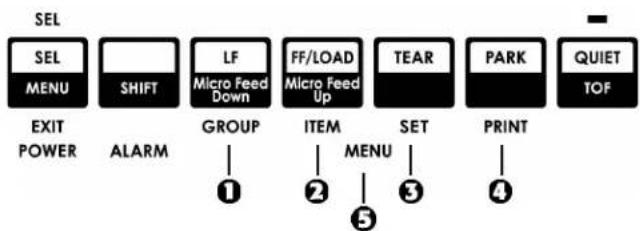
GROUP Key
Prints the next Group in the Menu.
With the SHIFT key, prints the previous Group.
② ITEM Key
Prints the next Item in the Group.
With the SHIFT key, prints the previous Item in the Group.
3 SET Key
Prints the next setting for an Item.
With the SHIFT key, prints the previous setting for an Item.
4 PRINT Key
Prints a copy of all the Menu settings.
With the SHIFT key, prints the current settings for the Group selected.
⑤ MENU Light
Glows when the printer is in the Menu Mode.
Entering and Exiting Menu Mode
To enter or exit the Menu Mode, hold SHIFT while pressing SEL.
Resetting the Menu to the Factory Defaults
Note: Please print the current Menu Mode settings before you reset or change them. This is the only way to have a record of the settings.
To reset the Menu to the standard settings (factory defaults):
1 Turn the printer off.
2 Press SEL + LF while turning the printer on.
Printing the Menu Settings
Printing the Current Menu Settings
1 Make sure paper is loaded in the printer.
2 Press and hold SHIFT, then press SEL to enter the Menu Mode.
3 Press PRINT (PARK key).
Printing All Menu Settings
To print out a listing of the settings for all menu items, regardless of the emulation selected or the accessories installed:
1 Make sure paper is loaded in the printer.
2 Press and hold SHIFT, then press SEL to enter the Menu Mode.
3 Press and hold SHIFT, then press PRINT QUALITY.
Changing the Menu Settings
Note: Please print the current Menu Mode settings before you reset or change them. This is the only way to have a record of the settings.
1 Press and hold SHIFT, then press SEL to enter the Menu Mode.
2 Use the GROUP, ITEM and SET keys to make your changes:
a Press GROUP until the Group you wish to change appears in the first column.
b Press ITEM until the Item you wish to change appears in the second column.
c Press SET until the setting you want appears in the third column.
3 Press and hold SHIFT, then press SEL to exit the Menu Mode and save your settings.
Important!
If you turn off the printer without first exiting the Menu Mode, the changes you have made will be lost.
Menu Settings Table
For a complete explanation of each menu item, see “Explanations of Menu Items” later in this chapter.
The table below shows the items which may appear in the menu. Settings which are engaged at the factory (defaults) are set in bold italic. Some groups or entries will only appear when a specific emulation is engaged, as noted.
| Group Item Settings (Defaults are set in bold italic) | ||
| Printer Control Emulation Mode IBM PPR, Epson FX, ML | ||
| Font | Print ModeDRAFT Mode HSD, SSDPitch 10 cpi, 12 cpi, 15 cpi,Proportional Spacing No, YesStyle Normal, ItalicsSize Single, Double | LQ Courier, LQ Roman, LQ Swiss, LQ Swiss Bold, LQ Orator, LQ Gothic,LQ Prestige, Utility, HSD7.1 cpi, 20 cpi |
| Symbol Sets | Character SetLanguage SetZero CharacterCode Page | Set I, Set II [Epson and IBM mode]Standard, Line Graphics, Block Graphics [ML Mode]American, French, German, British, Danish I, Swedish, Italian, Spanish I,Japanese, Norwegian, Danish II, Spanish II, Latin American, French Canadian,Dutch, PublisherSlashed, UnslashedUSA, Canada French, Multilingual, Portugal, Norway, BRASCII, Abicomp,Multilingual 858, ISO 8859-15 |
| Rear Feed Line Spacing 6 LPI, 8 LPIForm Tear-OffSkip Over Perforation No, YesPage Width (wide model) 13.6", 8"Page Length | Off, 500 ms, 1 sec, 2 sec11", 11-2/3", 12", 14", 17", 5", 3", 3.5", 4", 5.5", 6", 7", 8", 8.5" | |
| Bottom Feed Line Spacing 6 LPI, 8 LPIForm Tear-Off Off, 500 ms, 1 sec, 2 secSkip Over Perforation No, YesPage Width (wide model) 13.6", 8"Page Length | 11", 11-2/3", 12", 14", 17", 5", 3", 3.25", 3.5", 4", 5.5", 6", 7", 8", 8.5" | |
| Top Feed Line Spacing 6 LPI, 8 LPIForm Tear-Off*Bottom Margin Valid, InvalidPage Width (wide model) 8", 13.6"Page LengthWait TimePage Length Control | Off, 500 ms, 1 sec, 2 sec11", 11-2/3", 12", 14", 17", 5", 3", 3.25", 3.5", 4", 5.5", 6", 7", 8", 8.5"500 ms, 1 sec, 2 secby Actual Page Length, by MENU Setting | |
| Set-Up Graphics Bi-directional, Uni-directional7 or 8 Bit Graphics†Receive Buffer SizePaper Out Override | 8, 71 Line, 32K, 64K, 128KNo, Yes | |
* Appears only when the optional Roll Paper Stand is installed.
Appears only when the MICROLINE emulation is selected.
Menu Settings Table (Continued)
| Group Item Settings (Defaults are set in bold italic) | ||
| Setup (cont.) | Print Registration 1 | 0, range to 0.25 mmm to the right or left, set in 0.05 mm increments• press SEL to shift registration to the left;• press SHIFT + SEL to shift registration to the right. |
| Print Registration 2 | 0, range to 0.25 mmm to the right or left, set in 0.05 mm increments• press SEL to shift registration to the left;• press SHIFT + SEL to shift registration to the right. | |
| 7 or 8 Bits Data Word* 8, 7Operator Panel Function Full Operation, Limited OperationReset Inhibit No, Yes | ||
| Print Suppress Effective No | Yes | |
| Auto LF | No, Yes | |
| Auto CR† | No, Yes | |
| CSF Bin Select** | Bin 1, Bin 2 | |
| Print DEL Code* | No, Yes | |
* Appears only when MICROLINE emulation is selected.
Appears only when the IBM emulation is selected.
** Appears only if the optional Cut Sheet Feeder is installed.
Menu Settings Table (Continued)
| Group Item Settings (Defaults are set in bold italic) | ||
| SI Select Pitch (10 cpi)* 15 cpi, 17.1 cpiSI Select Pitch (12 cpi)* 12 cpi, 20 cpiTime Out Print Valid, InvalidAuto Select No, YesCentering Position DEFAULT, MODE 1, MODE 2CSF Type† Wide, NarrowPower Saving Enable, DisablePower Save Time 5 min, 10 min, 15 min, 30 min, 60 min | ||
| Parallel I/F | I-PrimePin 18 +5V, OpenAuto Feed XT**Bi-Direction | Buffer Print, Buffer Clear, InvalidInvalid, ValidEnable, Disable |
* Appears only when the IBM emulation is selected.
^ Appears only when optional Cut Sheet Feeder is installed.
** Appears only if the Epson emulation is selected.
Menu Settings Table (Continued)
| Group Item Settings (Defaults are set in bold italic) | ||
| Serial IF* Parity | None, Odd, Even | |
| Serial Data 7/8 Bits 8 Bits, 7 | Bits | |
| Protocol Ready/Busy, X/On | X/Off | |
| Diagnostic Test No, Yes | ||
| Busy Line SSD-, SSD+, DTR, RTS | ||
| Baud Rate | 19200 bps, 9600 bps, 4800 bps, 2400 bps, 1200 bps, 600 bps, 300 bps | |
| DSR Signal Valid, Invalid | ||
| DTR Signal Ready on Power | Up, Ready on Select | |
| Busy Time | 200 ms, 1 sec. | |
| CSF Bin 1* Line | Spacing 6 LPI, 8 LPIBottom Margin Valid, InvalidPage Width (Wide model) 8", 13.6"Page Length | 11", 11-2/3", 12", 14", 17", 5", 3.5", 4", 5.5", 6", 7", 8", 8.5" |
| CSF Bin 2* Line | Spacing 6 LPI, 8 LPIBottom Margin Valid, InvalidPage Length | 11", 11-2/3", 12", 14", 17", 5", 3.5", 4", 5.5", 6", 7", 8", 8.5" |
* Appears only when the optional Cut Sheet Feeder is installed.
Explanations of Menu Items
These explanations are in alphabetical sequence to make it easier to look them up. Some items only appear when optional accessories are installed; others appear in several groups in the menu.
7 or 8 Bit Graphics, Default = 7
Change this setting to 8 if your system uses 8-bit graphics.
7 or 8 Bit Data Word, Default = 8
Change this setting to 7 if your system uses 7-bit data word lengths.
Auto CR, Default = No
IBM emulation only. If you want the printer to automatically add a carriage return when a Line Feed is received at the end of a line, change the setting to Yes.
Auto LF, Default = No
If your printout is consistently double spaced, select No; if it overprints, select Yes.
Auto Feed XT, Default = Invalid
Epson emulation only. In the Epson emulation, the XT signal on pin 14 of the parallel interface can control automatic line feed. Some interface cables are wired in such a way that automatic line feed is always in effect: this item eliminates this potential problem. If your system uses pin 14 of the parallel interface to control automatic line feed, change the setting to Valid.
Auto Select, Default = No
Determines whether or not your printer will automatically be selected after you load in paper. With the factory default engaged, the printer will be deselected so that you can set the Top of Form. If you always use the same Top of Form position, change the setting to Yes.
Baud Rate, Default = 9600 bps
Appears only if optional Serial Interface is installed. Set this to match your system's transmission speed.
Bi-direction, Default = Enable
Change this setting if you wish to disable bidirectional transmission (PnP) in Nibble mode.
Bottom Margin, Default = Valid
Change to Invalid if you want the printer to ignore the bottom margin setting.
CAUTION!!
Setting the Bottom Margin to Invalid can cause loss of data and damage the printhead by allowing printing without paper.
Busy Line, Default = SSD-
Appears only when the optional Serial Interface is installed. If Ready/Busy protocol (factory default) is selected, you can choose which line your system monitors for a busy signal:
- SSD -9V, select SSD-
- SSD +9V, select SSD+
- DTR -9V, select DTR
- RTS -9V, select RTS
Busy Time, Default = 200 ms
Appears only when the optional Serial Interface is installed. Sets the length of the busy signal when the Ready/Busy protocol (factory default) is engaged,
Centering Position, Default = DEFAULT
Used to limit printhead travel when printing narrow columns.
- Select Mode 1 for the narrow carriage printer.
- Select Mode 1 or Mode 2 for the wide carriage printer.
Character Set, Default = IBM Set I
Epson and IBM emulations only. Use this to switch character sets to IBM Set II
Character Set, Default = Standard
MICROLINE emulation only. Use this to switch the character set to Line Graphics.
Code Page, Default = USA
Choose the Code Page character set you wish to use: USA, Canada French, Multilingual, Portugal, Norway, BRASCII, Abicomp, Multilingual 858, or ISO 8859-15.
CSF Bin Select, Default = Bin 1
Appears only when the optional Dual-Bin Cut Sheet Feeder is installed. Use this to switch to Bin 2 as the default.
CSF Type, Default = Wide
To avoid paper jams, change this setting to Narrow if you are using the optional Cut Sheet Feeder on the wide model ML421 printer.
Diagnostic Test, Default = No
Appears only when the optional Serial Interface is installed. Select yes to perform a diagnostic test of the serial interface.
DRAFT Mode, Default = HSD
Applies only when the Print Mode is set to DRAFT. Selects the draft mode to be used: HSD (High Speed Draft) or SSD (Super Speed Draft).
DSR Signal, Default = Valid
Appears only when the optional Serial Interface is installed. Used with the Ready/Busy protocol (factory default) to select the way your system handles the DSR signal.
DTR Signal, Default = Ready on Power Up
Appears only when the optional Serial Interface is installed. Change to Ready on Select if the DTR signal is required when the printer is selected (leave as Ready on Power Up if the DTR signal is required when the printer is turned on).
Emulation Mode, Default = IBM PPR
Selects the printer command set (emulation) you want to engage.
ESC SI Pitch, Default = 17 cpi
Sets the character pitch used when the ESC SI command is received.
Form Tear-Off, Default = Off
Choose 500 ms, 1 sec, or 2 sec to turn the Form Tear-Off feature on and to set the time interval for the printer to wait before advancing the paper.
Graphics, Default = Bi-directional
Change to uni-directional graphics for better registration, but slower printing. With this set for bi-directional, you can optimize the registration using the Print Registration setting in the Menu.
I-Prime, Default = Buffer Print
Determines what the printer will do when it receives the
I-Prime signal from the software.
- Buffer Print: prints out the buffer contents before resetting.
- Buffer Clear: dumps the buffer contents immediately.
- Invalid: causes the printer to ignore the I-Prime command. Select this setting if you wish to enter settings through the printer's control panel which will not be automatically overridden by the software's settings when the I-Prime signal is sent.
Language Set, Default = American
Replaces certain standard symbols with special characters used in foreign languages.
Line Spacing, Default = 6 lpi
Change to 8 lines per inch (lpi) to get more lines on a page.
Operator Panel Function, Default = Full Operation
Change to Limited Operation to deactivate the PRINT QUALITY and CHARACTER PITCH buttons, so that these features can only be controlled through your software. This prevents these from being changed from the control panel when several people are using the printer.
Important!
This feature also prevents access to the Menu. To access the Menu in these circumstances, turn the printer off, then hold down the SEL key while turning on the printer.
Page Length, Default = 11"
Selects the length of the paper you are using. This enables the printer to keep track of the initial printing position (TOF) on each page.
Page Length Control, Default = by Actual Page Length
If you are printing single sheets no longer than 17 inches and wish the printer to acknowledge the menu setting for Top Feed Page Length, change the setting to “by Menu Setting.”
Page Width, Default = Depends on Feed Path
Wide carriage model only.
For rear and bottom paths, the default is 13.6". Change to 8" if you will be printing on narrow paper. This prevents printing on the platen which can damage the printhead and the platen, and can cause loss of data.
For the top feed path the default is 8". Change to 13.6" to print on wide paper.
Paper Out Override, Default = No
Senses when less than 1" (25 mm) of paper remains and stops printing. Change to Yes to override the sensor and print closer to the bottom of the page.
Caution!!
Engaging Paper Out Override can cause loss of data and damage the printhead by allowing printing without paper.
Parity, Default = None
Appears only when the optional Serial Interface is installed. Selects the type of parity your system uses: None, Odd or Even.
Pin 18, Default = +5V
Sets the signal on pin 18 to +5 volts or open.
Pitch, Default = 10 cpi
Choose the character width, in characters per inch (cpi).
Power Save Time, Default = 5 min
Sets the interval the printer waits for more data before it goes into the power save mode. Power Saving must be set to Enable (the factory default) for this to be effective.
Power Saving, Default = Enable
Change to Disable if you wish to prevent the printer from entering the Power Save mode after the selected interval.
Print Mode, Default = Utility
Choose the quality and typeface of printing. Switch to NLQ Courier or NLQ Gothic for Near Letter Quality printing. If you are printing draft-type documents, select DRAFT, then select either HSD or SSD under DRAFT Mode. Both of these Items are in the Font Group.
Print Registration, Default = 0
Change the setting as required to obtain the best registration for bi-directional printing.
Print Suppress Effective, Default = Yes
If your system uses the DC1 and DC3 codes for something other than the print suppress mode, change the setting to No.
Proportional Spacing, Default = No
Change the setting to Yes to engage proportional spacing of characters.
Protocol, Default = Ready/ Busy
Appears only if the optional Serial Interface is installed. Change to X-ON / X-Off if that is the type of protocol your system uses.
Receive Buffer Size, Default = 64K
Selects the amount of memory devoted to holding received data. Choosing 1 Line will tie up your computer while printing, but if you abort the print job, the printer will stop much sooner.
Reset Inhibit, Default = No
Select Yes if you wish the printer to ignore the reset command sent by software. This prevents your software from changing the settings you make through the front panel controls or through printer commands.
Note: This will also prevent your software from clearing out existing settings when you finish printing one document and switch to another.
Serial Data 7/8 Bits, Default = 8 Bits
Appears only if the optional Serial Interface is installed. Change to 7 Bits if you systems uses a 7-bit data format.
SI Select Pitch 10 cpi, Default = 17.1 cpi
IBM emulation only. Sets the pitch to be engaged when the printer control panel is set for 10 cpi and the SI command is received.
SI Select Pitch 12 cpi, Default = 20 cpi
IBM emulation only. Sets the pitch to be engaged when the printer control panel is set for 12 cpi and the SI command is received.
Size, Default = Single
Change to Double for double width and height printing.
Skip Over Perforation, Default = No
Change to Yes if you want the printer to go to the next page when it comes within 1" (25 mm) of the bottom of the page. Keep it set to No if your software has its own page formatting controls.
Style, Default = Normal
Change to italics if you want the printed characters to be slanted.
Time Out Print, Default = Valid
If your software spends a long time processing between portions of data it feeds to the printer, change the setting to Invalid to keep your printer from dumping the received data while it is waiting for more.
Wait Time, Default = 1 sec
Sets the amount of time the printer will wait for more data before moving to the form tear-off position.
Zero Character, Default = Slashed
If you do not want the printer to use a slash to distinguish the number zero from the capital letter O, change the setting to Unslashed.
Chapter 5: Maintenance
Replacing the Ribbon Cartridge
Important!
Make sure you have the correct replacement ribbon for the your printer. The wrong ribbon will not print when installed in your printer. Look for the printer model number on the ribbon package.
Ribbon Cartridge Handling
- Leave unused ribbon cartridges in their packages until needed.
- Careful; the ribbon ink may cause permanent stains.
- Ribbon ink on skin or clothing can usually be removed with soap and water.
1 Make sure the printer is turned OFF.
2 Open the access cover and center the printhead.
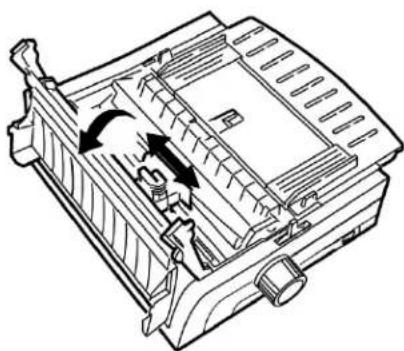
natural_image
Technical line drawing of a mechanical device with internal components and directional arrows indicating motion (no text or symbols)CAUTION!
The printhead may be HOT!
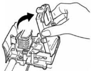
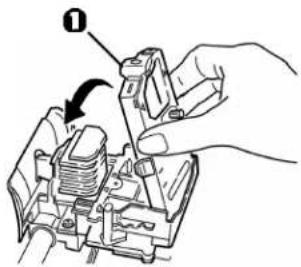
3 Swing the used ribbon cartridge up off the printhead, lift it out, and discard it.
natural_image
Hand holding a mechanical component with a black arrow indicating rotation (no text or symbols)4 Unpack the new ribbon cartridge and install it.
Important!
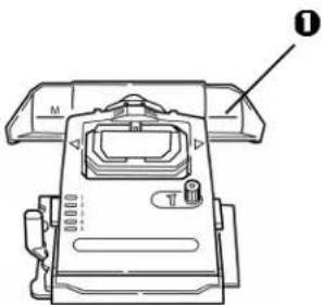
Do not remove the ribbon shield (1) from the ribbon!
text_image
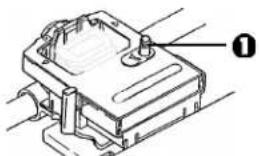
Diagram showing a hand operating a mechanical component with labeled part 1 and directional arrow indicating rotation or assembly.5 Turn the take-up knob (1) in the direction of the arrow to take up any ribbon slack.
natural_image
Technical line drawing of a mechanical component with no visible text or symbols6 Close the access cover and turn the printer back on.
CAUTION!
If ribbon should contact the eyes:
Flush eyes with large quantities of water for 15 minutes, keeping eyelids open with fingers. Seek medical attention.
If ribbon should contact the skin
Wash thoroughly with soap and water.
For more information
See the Material Safety Data Sheet in your Warranty, Regulatory, and Safety Information booklet.
Loading Paper
Rear Feed
Note: If you have any paper in the paper path, remove it before installing rear feed paper.
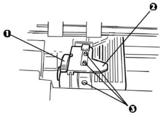
Lock Lever
② Upper Tractor Cover
3 Pins
text_image
Technical diagram of a mechanical assembly with numbered components labeled 1, 2, and 3Loading Rear Feed Paper from the Back of the Printer
Note: These instructions assume you have ready access to the back of the printer. If you do not, skip down to "Loading Rear Feed Paper from the Front of the Printer."
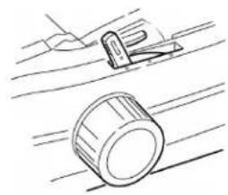
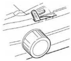
1 Make sure the paper lever is forward (position marked "REAR").
natural_image
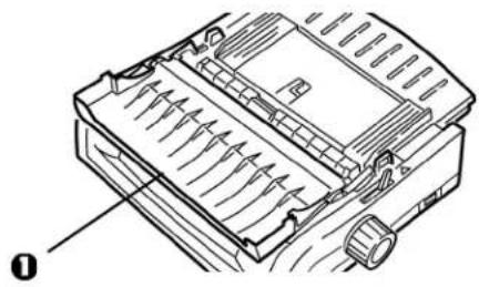
Simple line drawing of a tool and a mechanical component (no text or symbols)2 Open the access cover (1).
natural_image
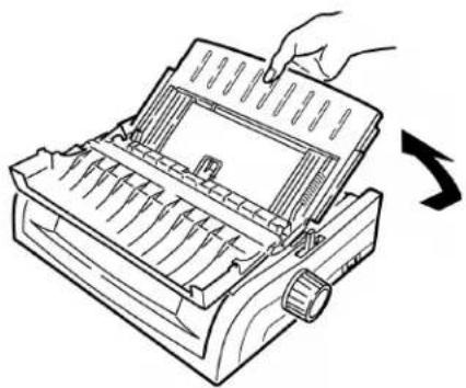
Technical line drawing of a mechanical component with internal channels and a knob (no text or symbols)3 Grasp the sheet guide. Lift it slightly, then slide it back.
natural_image
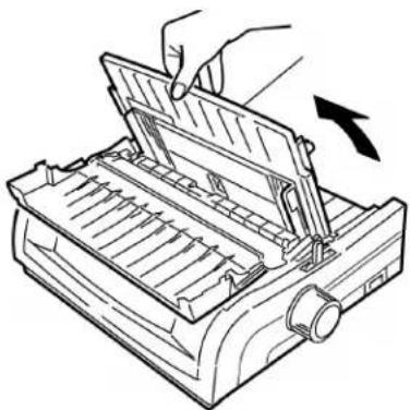
Line drawing of a hand inserting a card into a printer (no text or symbols)4 Pivot the sheet guide forward and gently rest it against the roller assembly.
Careful!
If you push the sheet guide too hard against the roller assembly, it may dislodge it. If it does, be sure to reseat the roller assembly before continuing.
natural_image
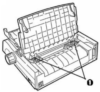
Line drawing of a hand using a device to press or adjust a tray (no text or symbols visible)5 From the back of the printer, locate the tractors (1).
natural_image
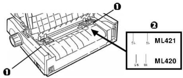
Technical line drawing of a mechanical assembly with no visible text or symbols6 Open the lock levers (1) and move the right tractor (as viewed from the back of the printer) to the reference mark (2) matching the width of the paper you are loading. Then close the lock lever on the right tractor:
text_image
① ② SL SL ML421 S6 01 ML420Note: The movement of the right tractor is limited to ensure that the paper covers the paper sensor.
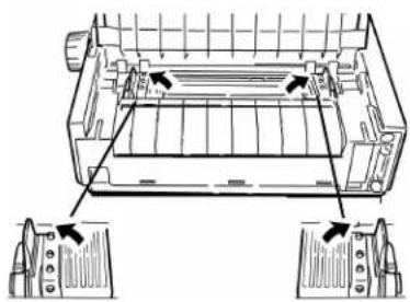
7 Open the tractor covers.
natural_image
Technical line drawing of a mechanical component with two views (no text or symbols)46 Microline 420/421 User's Guide
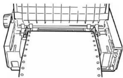
8 Place continuous forms paper on the first two pins of either tractor.
Important!
You must keep the number of paper holes engaged on either pin the same. If you don't the paper will skew and jam.
natural_image
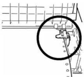
Technical line drawing of a mechanical component with internal channels and mounting holes (no text or symbols)9 Close the right tractor cover.
natural_image
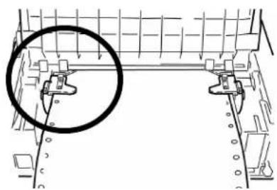
Pure mechanical diagram showing a gear or cam mechanism without any text, numbers, or symbols10 Adjust the left tractor until the holes in the paper are centered on the pins then lock the lever and close the left tractor cover.
Note: If the paper is too loose or too tight it can cause jams.
natural_image
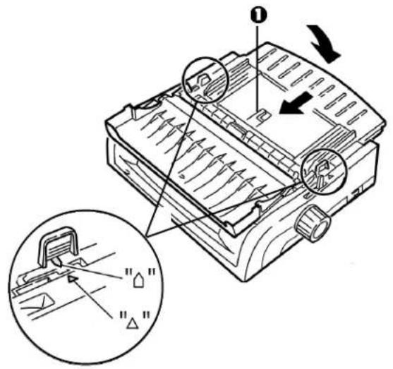
Technical line drawing of a mechanical assembly with a circled detail (no text or symbols)11 Lower the sheet guide and slide it toward the front of the printer until the marks align.
text_image
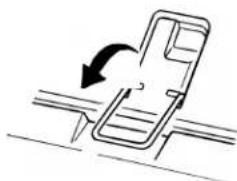
Technical diagram of a mechanical device with labeled parts and directional arrows indicating motion or assembly.12 Place the wire guide ("1" in the illustration for the step above) in the sheet guide on the pull-up roller assembly.
natural_image
Diagram of a mechanical component with an arrow indicating rotational motion (no text or symbols)13 Press FF/LOAD.
Note: The factory default setting for the Top of Form (where the printing should begin) is 1" down from the top of the page. To change the setting, see "Top of Form (TOF)" in Chapter 3.
Loading Rear Feed Paper from the Front of the Printer
Note: These instructions assume you do not have ready access to the back of the printer. If you do, go back to "Loading Rear Feed Paper from the Rear of the Printer" earlier in this chapter.
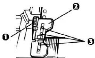
Lock Lever
② Upper Tractor Cover
3 Pins
text_image
Technical diagram of a mechanical assembly with numbered components labeled ①, ②, and ③I Make sure the paper lever is forward (position marked "REAR").
natural_image
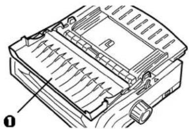
Simple line drawing of a tool and a mechanical component on a surface (no text or symbols)2 Open the access cover (1).
natural_image
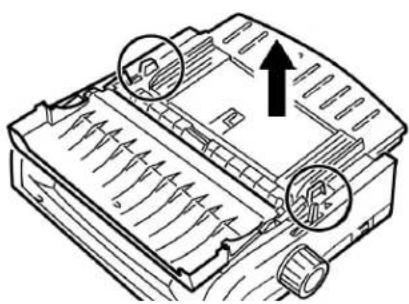
Technical line drawing of a mechanical device with internal components and directional arrows (no text or symbols)3 Grasp the tabs and lift off the sheet guide.
natural_image
Technical line drawing of a mechanical component with directional arrows and circular features (no text or symbols)4 Pull up on the lock levers to release them.
Note: The movement of the left tractor (as viewed from the front of the printer) is restricted to ensure that the paper covers the paper out sensor.
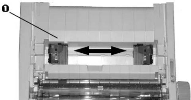
5 You will find reference marks (1 in illustration below) on the printer for the two most common paper sizes:

text_image
ML420: 10 9.5 ML421: 16 156 Move the left tractor to the position to match your paper size and push back on the lever to lock it in place, then move the right tractor to fit the width of the paper.
natural_image
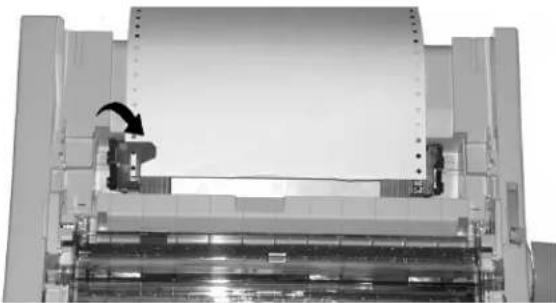
Mechanical assembly diagram showing a cylindrical component with internal components and directional arrows (no text or symbols)7 Open the tractor covers and place continuous forms paper on the first two pins of either tractor, then close the left tractor cover.
Important!
You must keep the number of paper holes engaged on either pin the same. If you don't the paper will skew and jam.
natural_image
Industrial machine with a rotating press mechanism (no visible text or symbols)50 Microline 420/421 User's Guide
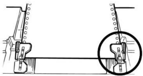
8 Adjust the position of the right tractor to center the holes in the paper on the pins. Then, close its tractor cover and push back the lock lever. Do not stretch the paper.
Note: If the paper is too loose or too tight it can cause jams.
natural_image
Mechanical assembly diagram showing a linkage mechanism with a magnified inset (no text or labels)9 Reinstall the sheet guide.

text_image
Technical diagram showing three steps of a vehicle chassis with labeled parts and an inset magnified view highlighting the component.Maintenance 51
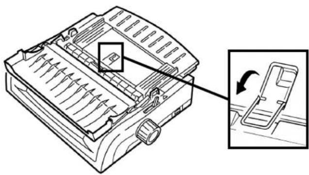
10Place the wire guide (1) in the sheet guide on the pull-up roller assembly.
natural_image
Technical line drawing of a mechanical component with an inset showing a close-up of the internal structure (no text or symbols)11 Press FF/LOAD.
Note: The factory default setting for the Top of Form (where the printing should begin) is 1" down from the top of the page. To change the setting, see "Top of Form (TOF)" in Chapter 3.
52 Microline 420/421 User's Guide
Top Feed (Single Sheets)
Note: If you have continuous form paper in the path, press PARK to remove it before loading single sheets.
1 Make sure the printer is on and deselected (SEL light off).
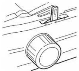
2 Place the paper lever in the center position (marked "TOP").
natural_image
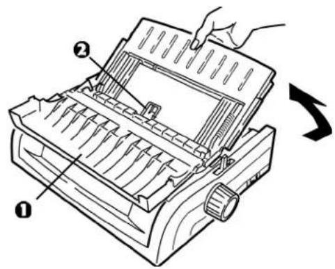
Simple line drawing of a mechanical component with motion lines, no text or symbols present3 Open the acoustic cover (1) and raise the sheet guide to the single-sheet position. Pivot the wire feed guide (2) up into the sheet guide.
text_image
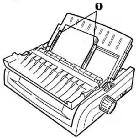
Diagram of a printer with labeled parts and directional arrow indicating rotation or change4 Adjust the paper feed guides (1) for the width of the paper, then place a sheet of paper in the separator. The paper will feed into the printer.
natural_image
Line drawing of a mechanical device with internal components and a labeled component (no text or symbols)Important!
If the paper does not feed in, remove it. Check the paper lever position. Make sure the ALARM light is on: if it is flashing, hold the SHIFT key and press the CHARACTER PITCH/RESET key. Reload the sheet of paper.
Note: The factory default setting for the Top of Form (where the printing should begin) is 1" down from the top of the page. To change the setting, see "Top of Form (TOF)" in Chapter 3.
Clearing Paper Jams
Rear-Feed Paper Jams
1 Turn off the printer.
2 Use the platen knob to back the paper all the way out of the printer.
CAUTION!
Make sure the printer is turned off before you open the access cover.
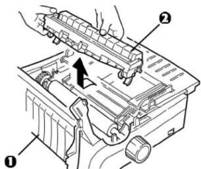
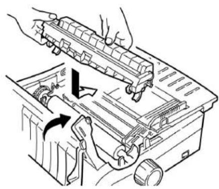
3 Open the access cover (1) and remove the pull-up roller assembly (2). Remove any torn pieces of paper.
text_image
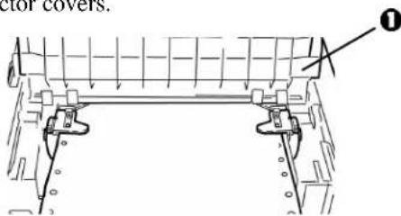
Technical diagram of a mechanical device with labeled parts and an arrow indicating direction or force5 Lift the sheet guide (1) and reload paper. Make sure you lock the tractor covers.
text_image
ector covers. ①5 Lower the sheet guide, then install the pull-up roller assembly and close the access cover.
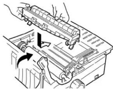
natural_image
Technical line drawing of a mechanical assembly with hands operating a component (no text or symbols visible)6 Turn on the printer and press FF/LOAD.
Rear-Feed, Repeating Paper Jams
If the paper keeps jamming, you may have:
- defective paper
- misaligned paper
- bits of paper stuck in the paper path
Defective Paper
Replace the paper with a fresh stack.
Misaligned Paper
1 Turn off the printer.
2 Use the platen knob to back the paper all the way out of the printer.
3 Tear off a couple of sheets of paper, leaving a new, clean, square-cut edge.
4 Reload the paper and turn the printer back on.
Bits of Paper Stuck in the Paper Path
1 Turn off the printer.
2 Use the platen knob to back the paper all the way out of the printer.
CAUTION!
Make sure the printer is turned off before you open the access cover.
3 Open the access cover (1) and remove the pull up roller assembly (2). Then grasp the tabs (3) on the sheet guide (4) and lift it off the printer.
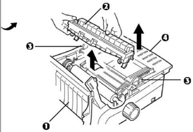
text_image
Diagram of a mechanical device with numbered parts and directional arrows indicating assembly or operation4 Remove any torn pieces of paper.
5 Fold some continuous-form paper over three times to make a page four sheets thick. Then, load it on the tractors and close and lock the covers.
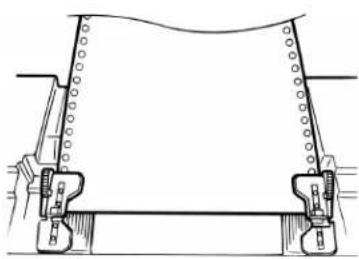
natural_image
Technical line drawing of a mechanical assembly with no visible text or symbols6 Use the platen knob to draw the quadruple-thick page around the platen. This brings out jammed pieces of paper.
7 Remove the paper pieces. Then, use the platen knob to back the paper out.
8 Load regular paper, close and lock the tractor covers.
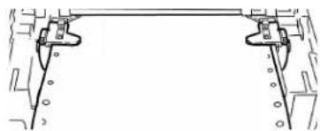
natural_image
Pure mechanical assembly diagram showing two vertical supports connected to a horizontal beam, without any text, labels, or symbols.9 Install the sheet guide, then install the pull-up roller assembly and close the access cover.
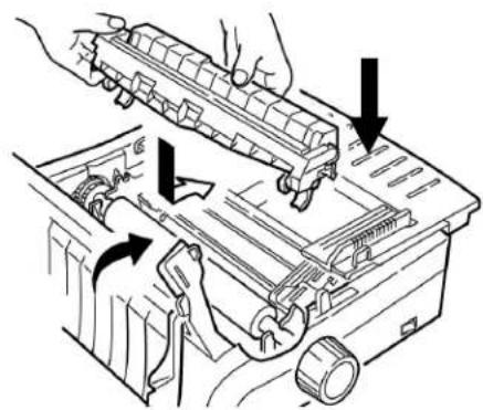
natural_image
Diagram of hands installing or adjusting a mechanical component with arrows indicating assembly (no text or symbols present)10 Turn the printer on and press FF/LOAD.
Single-Sheet Paper Jams
1 Turn off the printer.
2 Use the platen knob to back the paper out.
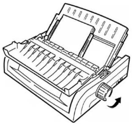
natural_image
Line drawing of a mechanical printer or scanner with a scroll wheel and paper holder (no text or symbols)3 Open the access cover (1) and remove the pull-up roller assembly (2).
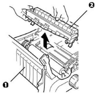
text_image
Technical diagram showing mechanical assembly with labeled parts and directional arrow indicating motion4 Remove any torn pieces from around the carriage.
5 Reinstall the pull-up roller assembly and close the access cover.
Cleaning the Housing
You should clean the printer housing every six months (or after about 300 hours of operation).
CAUTION!
Never use strong solvents or strong detergents on the cabinet—they could damage the housing.
1 Turn off the printer.
2 Use the platen knob to back the paper out of the printer.
CAUTION!
Make sure the printer is turned off before you open the access cover.
3 Open the access cover (1) and remove the pull-up roller assembly (2).
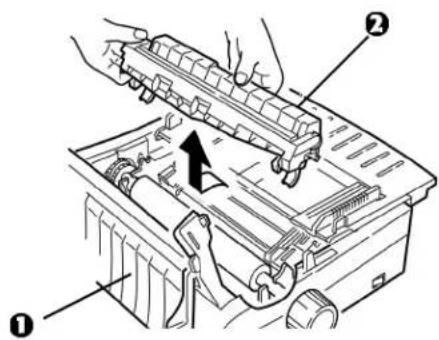
text_image
Technical diagram showing a mechanical assembly with labeled parts, including a tool and directional arrow indicating movement.4 Use a clean, dry cloth to dust around the carriage shaft and platen. Remove any loose bits of paper.
5 Reinstall the pull-up roller assembly and close the access cover.
natural_image
Technical line drawing of a mechanical assembly with hands operating a component (no text or symbols)Chapter 6: Troubleshooting
General Information
Here are some general things to check before proceeding with detailed troubleshooting.
- Is the printer plugged in and turned on?
- Are the connections (power and interface) secure?
- Is the product being operated under the proper ambient conditions?
- Does the paper being used meet the specifications for this product?
• Is the paper properly installed? - Is the ribbon properly installed?
• Is an Oki ribbon being used? - Is the printhead gap correctly set?
- Are the correct printer drivers being used for the printer?
Note: Settings in your software application will normally override any settings in your printer driver.
Printer driver settings normally override settings from the printer menu or printer front panel.
Problems / Solutions
Problem
My word processor files do not print the way I have the menu and front panel set.
Solution
Remember:
- Settings in your software application can override settings in your printer driver.
- Your printer driver settings can override any settings from the printer menu or printer front panel.
Before sending a file to the printer, many word processors send either an “initialization string” or an I-Prime signal to the printer.
The initialization string contains codes that override the panel and menu settings. To change your printer to ignore the reset code, enter the Menu Mode, go to the Set-Up group and change the setting for Reset Inhibit to Yes.
The I-Prime signal will automatically override any front panel settings you have made. To eliminate this problem, enter the Menu Mode, go to the Parallel Interface group and change the setting for I Prime to Invalid.
For more information on changing menu settings, see “Changing the Menu Settings” in Chapter 4.
Problem
Nothing happens when I turn on the printer.
Solution
Check the power cord connection to the outlet and to the printer. If you are using a power strip, make sure it is turned on, and that the fuse hasn't blown or that the circuit breaker hasn't tripped.
Problem
The printer does not print when the computer sends data.
Solutions
1 Is the SEL light on? If not, press the SEL key.
2 Check that the interface cable is securely connected to both the printer and the computer.
3 If you have the optional serial interface board installed, check to be sure that it is firmly seated in the printer.
Problem
I'm getting strange symbols, incorrect fonts, etc., when I try to print a document.
Solutions
1 Check to be sure that the printer driver you have selected in your software matches the printer emulation.
- Press SHIFT and SEL keys, then press GROUP key.
- This will print a line showing the emulation you have selected.
2 If you have embedded any printer commands in your software, check to be sure that you entered them correctly.
Problem
Ink smears on the paper when I print narrow columns.
Solution
This may be caused by excessive printhead travel from the centering position. Enter the Menu and set the Centering Position to MODE 1. See “Using Your Printer, Menu Mode.”
For the wide-carriage printer, if MODE 1 doesn't work, try setting the Centering Position to MODE 2.
Problem
I've installed a new ribbon and the printing is smeared and streaked.
Solution
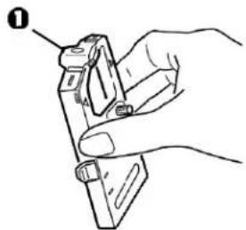
The ribbon shield (1) is either loose or missing.
natural_image
Hand holding a mechanical component with a label pointing to it (no text or symbols present)Remove the ribbon cartridge and check the ribbon shield.
- If it is loose, secure it.
- If it is missing, find it and install it.
Problem
There are dots missing in my printouts.
Solution
The head gap may not be set correctly. Try moving the headgap lever to a lower setting. If that doesn't help, the printhead may be damaged; call for service.
Problem
The ALARM light is flashing.
Solution
Try turning the printer off and then back on again. If the light still blinks, call for service.
Problem
The ALARM light is on and the Character Pitch 10 light is flashing.
Solution
This indicates that the paper lever is set at the wrong position for the paper you are trying to use. Move it to the proper setting.
Problem
The ALARM light is on and the Character Pitch 15 light is flashing.
Solution
This indicates a paper jam. Press the SEL key and correct the paper jam situation. See “Clearing Paper Jams,” in Chapter 4.
Problem
The printer needs paper. The ALARM is not on and I can't load paper.
Solution
1 Press and release the SEL key.
2 Press and hold the SHIFT key and press the RESET / CHARACTER PITCH key.
The ALARM light comes on and you can now load paper.
Problem
Continuous-form paper sticks to the sheet guide.
Solution
In cold dry weather, static charges can build up and make the paper cling to the sheet guide. Try moving the paper guides together so that the paper rests on the guides rather than on the separator.
Problem
The Print Quality and Character Pitch keys on the front panel don't work.
Solution
The Operator Panel Function in the printer menu can be used to disable these buttons (Limited Function). If the printer is part of a customized system or if it is used by a number of people, the system manager may have used this option to make sure the printer is always set properly.
Check with your system manager before changing any menu settings.
Appendix A: Parts & Accessories
Purchasing Parts & Accessories
Before you purchase, know your printer model number (see the front of the unit) and have the correct part number and description of the item. Item descriptions and part numbers are provided in this section.
- Consult the dealer where your purchased your printer.
- Locate an Authorized Oki Data Reseller by visiting one of our web sites
http://my.okidata.com (allows you to register your product and personalize your own support needs)
http://www.okidata.com (provides general information)
• In the United States, purchase directly from Oki Data
- Via the Internet http://my.okidata.com http://www.okidata.com
- Via telephone Order toll-free by phone at 1-800-654-3282 (1-800-OKI-DATA) using VISA ^® , MasterCard ^® , or AmEx ^® .
• In Canada, call 888-309-4570.
Replacement Parts
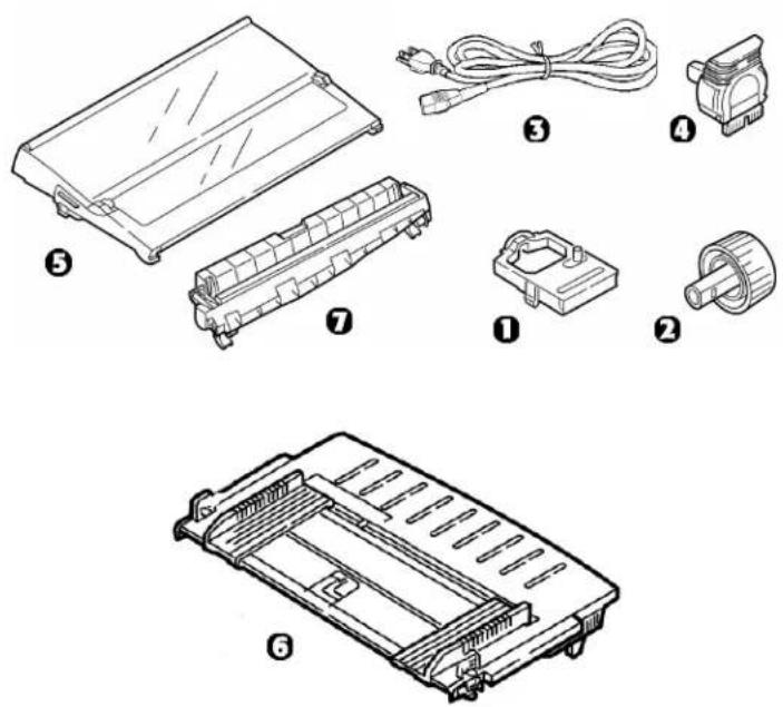
Item Part Number
Both Models
Ribbon Cartridge (1)---- 42377801
Platen Knob (2)---- 51902220
Power Cord (3) 56631801
Printhead (4) 41923901
Model ML420
Access Cover (5) 42115401
Sheet Guide (6) 51009509
Pull-Up Roller Assembly (7) 42044701
Model ML421
Access Cover (5) 42115301
Sheet Guide (6) 51009410
Pull-Up Roller Assembly (7) 42045701
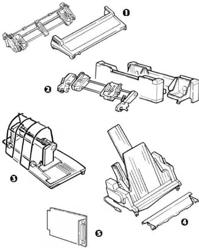
Accessories
Option Part Number
Model ML420
Pull Tractor, Top-Mount (1)---- 70030501
Push Tractor, Bottom-Mount (2) 70030701
Roll Paper Stand (3) 70023301
Model ML421
Pull Tractor, Top-Mount 70030601
Push Tractor, Bottom-Mount (2) 70030801
Both Models
Cut Sheet Feeder (4) 70030101
Serial Interface (5) 70012801
OkiLAN® 6120i 10/100 Base-T Ethernet
Internal Print Server (not shown) 70046501
OkiLAN 6020e 10/100 Base-T Ethernet
External Print Server (not shown) ---- 70036001
OkiLAN 6010 10 Base-T Ethernet
External Print Server (not shown) 70034401
Appendix B: Printer Control Codes
This section lists the most commonly used printer control codes.
You will find a comprehensive listing of the control codes (English only), on your Printer CD.
To access it:
1 Place the CD in your CD-ROM drive and wait for it to AutoPlay.
2 Select your printer model, then click Continue.
3 Click Documentation and follow the on-screen prompts to view the file.
IBM Proprinter III Commands
| IBM Command ASCII Decimal | ||
| Backspace BS 8 | ||
| Carriage Return CR 13 | ||
| Character Pitch | ||
| Select 10 cpi DC2 18 | ||
| Select 12 cpi ESC : 27 58 | ||
| Select 15 cpi ESC g 27 103 | ||
| Select Condensed Print ESC SI, or SI 27 15, or 15 | ||
| Character Sets | ||
| IBM Set I | ESC 7 27 55 | |
| IBM Set II | ESC 6 27 54 | |
| Publisher | ESC ! Z | 27 33 90 |
| Slashed Zero | ESC ! @ | 27 33 64 |
| Unslashed Zero ESC ! A | 27 33 65 | |
| Double Width On ESC W 1 27 87 49 | ||
| Double Width Off ESC W 0 27 87 48 | ||
| Emphasized Printing On ESC E 27 69 | ||
| Emphasized Printing Off ESC F 27 70 | ||
| Enhanced Printing On ESC G 27 71 | ||
| Enhanced Printing Off ESC H 27 72 | ||
| Form Feed FF | 12 | |
| Form Length | ||
| n inches (n = 1 to 255) | ESC C NUL n | 27 67 0 n |
| n lines (n = 1 to 255) | ESC C n | 27 67 n |
| Horizontal Tab, Execute | HT | 9 |
| Italics On | ESC % G | 27 37 71 |
| Italics Off | ESC % H | 27 37 72 |
| IBM Command ASCII Decimal | ||
| Line Feed, Execute | ||
| w/ Carriage Return | LF | 10 |
| n/144" (n = 1 to 127) | ESC % 5 n | 27 37 53 n |
| n/216" (n = 0 to 255) | ESC J n | 27 74 n |
| Reverse | ESC ] | 27 93 |
| Auto Line Feed On | ESC 5 1 | 27 53 49 |
| Auto Line Feed Off | ESC 5 0 | 27 53 48 |
| Line Spacing | ||
| Set Spacing to 1/8" | ESC 0 | 27 48 |
| Set Spacing to 7/72" | ESC 1 | 27 49 |
| Set Spacing to n/72" (n = 0 to 255) | ESC A n | 27 65 n |
| Store Spacing Set by ESC A n | ESC 2 | 27 50 |
| Set Spacing to n/144" (n = 1 to 127) | ESC % 9 n | 27 37 57 n |
| Set Spacing to n/216" (n = 0 to 255) | ESC 3 n | 27 51 n |
IBM Proprinter III Commands (continued)
| IBM Command ASCII Decimal | |
| Overscore On ESC_1 27 95 49 | |
| Overscore Off ESC_0 27 95 48 | |
| Paper Out Sensor Off ESC 8 27 56 | |
| Paper Out Sensor On ESC 9 27 57 | |
| Print Quality, Select HSD ESC # 0 27 35 48 | |
| Print Suppress Mode OnML420 ESC Q ETX 27 81 3ML421 ESC Q SYN 27 81 22 | |
| Print Suppress Mode Off DC1 17 | |
| Proportional Spacing On ESC P 1 | 27 80 49 |
| Proportional Spacing Off ESC P 0 | 27 80 48 |
| Reset: Clear Print Buffer CAN | 24 |
| IBM Command | ASCII | Decimal |
| Software I-Prime | ESC } NUL 27 125 0 | |
| Stop Printing | ESC j | 27 106 |
| Subscript On | ESC S 1 27 83 49 | |
| Superscript On | ESC S 0 27 83 48 | |
| Subscript/Superscript Off | ESC T | 27 84 |
| Top of Form,Set at Current Position | ESC 4 27 52 | |
| Underline Printing On | ESC - 1 | 27 45 49 |
| Underline Printing Off | ESC - 0 | 27 45 48 |
| Uni-Directional Print On | ESC U 1 | 27 85 49 |
| Uni-Directional Print Off | ESC U 0 | 27 85 48 |
| Vertical Tab, Execute | VT | 11 |
Epson FX Commands
| Epson Command ASCII Decimal | ||
| Backspace BS 8 | ||
| Carriage Return, Execute CR 13 | ||
| Character Pitch Select 10 cpi ESC P 27 80 Select 12 cpi ESC M 27 77 Select 15 cpi ESC g 27 103 Begin 10 cpi ESC SI, or SI 27 15, or 15 | ||
| Cancel Condensed Print DC2 18 | ||
| Delete | DEL | 127 |
| Epson Command | ASCII Decimal | |
| Double Height On | ESC w 1 | 27 119 49 |
| Double Height Off ESC w 0 | 27 119 48 | |
| Double Width On | ESC W 1 | 27 87 49 |
| Double Width Off | ESC W 0 | 27 87 48 |
| Emphasized Print On | ESC E | 27 69 |
| Emphasized Print Off | ESC F | 27 70 |
| Enhanced Print On | ESC G | 27 71 |
| Enhanced Print Off | ESC H | 27 72 |
| Epson Set 1, Select | ESC t 0 | 27 116 48 |
| Epson Set 2, Select | ESC t 1 | 27 116 49 |
| Italic Printing On | ESC 4 | 27 52 |
| Italic Printing Off | ESC 5 | 27 53 |
| Form Feed | FF | 12 |
| Epson Command ASCII Decimal | ||
| Form Lengthn Inches (n = 1 to 22) ESC C NUL n 27 67 0 nn Lines (n = 1 to 127) ESC C n 27 67 n | ||
| Horizontal Tab HT 9 | ||
| JustificationLeft ESC a 0 27 97 48Center ESC a 1 27 97 49Right ESC a 2 27 97 50Full | ESC a 3 27 97 51 | |
| Line Feed, ExecuteSelect 10 cpi | ESC P | 27 80 |
| Select 12 cpi | ESC M | 27 77 |
| w/ Carriage Return | LF | 10 |
| n/216" (n = 0 to 255) | ESC J n | 27 74 n |
| n/144" (n = 0 to 127) | ESC % 5 n | 27 37 53 n |
| Reverse, n/216"(n = 0 to 255) | ESC j n | 27 106 n |
| Epson Command | ASCII | Decimal |
| Line Spacing, Set | ||
| n/144" (n = 0 to 127) | ESC % 9 n 27 37 57 n | |
| n/216" (n = 0 to 255) | ESC 3 n 27 51 n | |
| n/72" ESC A n(n = 0-85 or 128-213) | 27 65 n | |
| 1/6" | ESC 2 | 27 50 |
| 1/8" | ESC 0 | 27 48 |
| 7/72" ESC 1 | 27 49 n | |
| Paper Out Sensor Off | ESC 8 | 27 56 |
| Paper Out Sensor On | ESC 9 | 27 57 |
Epson FX Commands (continued)
| Epson Command ASCII Decimal | |
| Print Quality/Font | |
| Select HSD/SSD | |
| (depends on setting for Draft Mode) ESC ( 0 27 40 48 | |
| Select NLQ ESC x 1 27 120 49 | |
| Select Courier(NLQ only) ESC k 0 27 107 48 | |
| Select Gothic(NLQ only) ESC k 1 27 107 49 | |
| Select UTL ESC x 0 27 120 48 | |
| Print Speed | |
| Half-Speed On ESC s 1 27 115 49 | |
| Half-Speed Off ESC s 0 27 115 48 | |
| Print Suppress Mode On DC3 19 | |
| Print Suppress Mode Off | DC1 17 |
| Proportional Spacing On | ESC p 1 27 112 49 |
| Proportional Spacing Off | ESC p 0 27 112 48 |
| Epson Command ASCII Decimal | ||
| Reset Printer | ||
| Clear Buffer & Initialize | ESC @ | 27 64 |
| Clear Print Buffer | CAN | 24 |
| Skip Over Perforation, Cancel | ESC O | 27 79 |
| Software I-Prime | ESC } NUL | 27 125 0 |
| Subscript On | ESC S 1 | 27 83 49 |
| Superscript On | ESC S 0 | 27 83 48 |
| Subscript/Superscript Off | ESC T | 27 84 |
| Underline On | ESC - 1 27 45 49 | |
| Underline Off | ESC - 0 27 45 48 | |
| Uni-Directional Printing | ||
| One Line Only | ESC < 27 60 | |
| On | ESC U 1 | 27 85 49 |
| Off | ESC U 0 | 27 85 48 |
| Vertical Tab, Execute | VT | 11 |
Oki MICROLINE Standard Commands
| Oki Command ASCII Decimal | ||
| Backspace BS 8 | ||
| Carriage Return CR 13 | ||
| Character Pitch | ||
| Select 10 cpi RS 30 | ||
| Select 12 cpi FS 28 | ||
| Select 15 cpi ESC g 27 103 | ||
| Select 17.1 cpi GS 29 | ||
| Select 20 cpi ESC # 3 27 35 51 | ||
| Character Sets | ||
| Standard ESC ! 0 | 27 33 48 | |
| Block Graphic ESC ! 1 | 27 33 49 | |
| Line Graphics ESC ! 2 | 27 33 50 | |
| Publisher | ESC ! Z | 27 33 90 |
| Oki Command ASCII Decimal | ||
| Slashed Zero | ESC ! @ | 27 33 64 |
| Unslashed Zero ESC ! A | 27 33 65 | |
| Double Height On | ESC US 1 | 27 31 49 |
| Double Height Off | ESC US 0 | 27 31 48 |
| Double Width Printing | US 31 | |
| Emphasized Printing On | ESC T | 27 84 |
| Emphasized Printing Off | ESC I | 27 73 |
| Enhanced Printing On | ESC H | 27 72 |
| Enhanced Printing Off | ESC I | 27 73 |
| Form Feed | FF | 12 |
| Horizontal Tab, Execute | HT 9 | |
| Italic On | ESC ! / | 27 33 47 |
| Italic Off | ESC ! * | 27 33 42 |
| Line Feed Commands | ||
| w/ Carriage Return LF 10 | ||
| w/o Carriage Return ESC DC2 27 18 | ||
| n/144" (n = 0 to 127) ESC % 5 n 27 37 53 n | ||
| Reverse ESC LF 27 10 | ||
| Line Spacing | ||
| Set Spacing to 1/6" ESC 6 27 54 | ||
| Set Spacing to 1/8" ESC 8 27 56 | ||
| Set Spacing, in n/144" | ||
| (n = 0 to 127) ESC % 9 n 27 37 57 n | ||
| Skip Over Perforation | ||
| 1/3" increments | ||
| (n = 1 to 9) | ESC G n n | 27 71 n n |
| Default | ESC % S 0 | 27 37 83 48 |
| Oki Command ASCII Decimal | ||
| Paper Out Sensor Off | ESC E 1 | 27 69 49 |
| Paper Out Sensor On | ESC E 0 | 27 69 48 |
| Print Quality | ||
| Select HSD/SSD | ESC # 0 27 35 48 | |
| Select NLQ Courier | ESC 1 27 49 | |
| Select NLQ Gothic | ESC 3 27 51 | |
| Select Utility | ESC 0 27 48 | |
| Print Speed, Set to Full | ESC > | 27 62 |
| Print Speed, Set to Half | ESC < | 27 60 |
| Print Suppress On DC3 | 19 | |
| Print Suppress Off | DC1 | 17 |
| Proportional Printing | ||
| On | ESC Y | 27 89 |
| Off | ESC Z | 27 90 |
| Reset: Clear Print Buffer | CAN | 24 |
| Shift-In SI 15Shift-Out SO 14 | ||
| Software I-Prime ESC } NUL 27 125 0 | ||
| Subscript Printing On ESC L 27 76 | ||
| Subscript Printing Off ESC M 27 77 | ||
| Superscript Printing On | ESC J | 27 74 |
| Superscript Printing Off | ESC K | 27 75 |
| Underline Printing On | ESC C | 27 67 |
| Underline Printing Off | ESC D | 27 68 |
| Uni-Directional Print On | ESC - | 27 45 |
| Uni-Directional Print Off | ESC = 27 61 | |
| Vertical Tab, Execute | VT | 11 |
Appendix C: Specifications
Note: Specifications are subject to change without notice.
Print Method
Impact dot matrix
Printhead
9 pins, 0.30 mm (0.0118") diameter, with thermal protection
Interfaces
Standard: Centronics parallel, IEEE-1284 compliant USB 1.1
Optional: RS-232C Serial
Ethernet Print Servers:
6120i 10/100 Base-T, Internal
6020e 10/100 Base-T, External
6010e 10 Base-T, External
Receive Buffer Size
Maximum 128K
Reliability
Ribbon Life
4 million characters, on average, 10 cpi utility
Printhead Life
400 million characters average in 10 cpi utility mode at 25% duty and 35% page density
Mean Time Between Failures (MTBF)
20,000 hours at 25% duty cycle and 35% page density
Mean Time to Repair (MTTR)
15 minutes
Emulations (co-resident)
- IBM Proprinter III
- Epson FX
• Oki MICROLINE Standard
Print Speed
| Speed Mode (Characters per Second) |
| Super Speed Draft (SSD) 570 cps |
| High Speed Draft (HSD) 507 cps |
| Utility 380 cps |
| Near Letter Quality (NLQ) 95 cps |
Characters per Line (cpl)
| Setting ML420 ML421 |
| 10 cpi 80 cpl 136 cpl |
| 12 cpi 96 cpl 163 cpl |
| 15 cpi 120 cpl 204 cpl |
| 17.1 cpi 137 cpl 233 cpl |
| 20 cpi 160 cpl 272 cpl |
Graphics Resolution
| Emulation Density (Dots per inch) |
| Max. Resolution |
| IBM, Epson Single 60 x 216 dpi |
| Double 120 x 216 dpi |
| Quadruple 240 x 216 dpi |
| Oki MICROLINE Single 72 x 72 dpi |
| Double 144 x 144 dpi |
| Quadruple 288 x 144 dpi |
Resident Fonts
| Print Quality Available Fonts |
| Near Letter Quality Courier, Gothic |
| Utility Gothic |
| High Speed Draft Gothic |
| Super Speed Draft Gothic |
Bar Codes
- Code 39
- UPC A, UPC E
• EAN 8, EAN 13 - Interleaved 2 of 5
• Code 128
• Postnet
Paper Thickness: Tractor Feed
Rear Feed: 0.014" (0.36 mm) maximum
Bottom Feed: 0.017" (0.44 mm) max.
Requires optional push or pull tractor.
Paper Specifications: ML420
Single (Cut) Sheets
Feed: Top Only
Weight: 14 to 24 lb. US Bond (52.6 to 90 g/m ^2 )
Width Range: 7.2" to 8.5" (183 to 216 mm)
Single-part, continuous forms
Feed: Rear, Bottom*
Weight: 12 to 24 lb. US Bond (45 to 90 g/m ^2 )
Width Range: 3" to 10" (76 to 254 mm)
Carbonless continuous forms (orig. + 4 copies)
Feed: Rear, Bottom*
Weight: 9 to 11 lb.
Width Range: 3" to 10" (76 to 254 mm)
Interleaf continuous forms (orig. + 4 copies)
Feed: Rear, Bottom*
Weight: 10 to 12 lb. paper, 9 lb carbon
Width Range: 3 to 10" (76 to 254 mm)
* Bottom feed requires optional pull or push tractor
Labels
Feed: Bottom* Only
Weight: Not applicable
Width Range: 3" to 10" (76 to 254 mm)
Envelopes, single feed
Feed: Top Only
Weight: Max. 24 lb.
Width Range: 6.5" to 9.5" (165 to 241 mm)
Envelopes, continuous feed, non-overlap type
Feed: Bottom* Only
Weight: Max. 24 lb.
Width Range: 6.5" to 9.5" (165 to 241 mm)
Card Stock
Feed: Bottom*
Weight: Max. 100 lb. Index (180 g/m ^2 )
Width Range: Not applicable
Paper Specifications: ML421
Single (Cut) Sheet
Feed: Top Only
Weight: 14 to 24 lb. US Bond (52.6 to 90 g/m ^2 )
Width Range: 7.2" to 14.3" (182.8 to 363.2 mm)
Single-part, continuous forms
Feed: Rear, Bottom*
Weight: 12 to 24 lb. US Bond (45 to 90g / m^2
Width Range: 3" to 16" (76.2 to 406.4 mm)
Carbonless continuous forms
Feed: Rear, Bottom*
Weight: 9 to 11 lb.
Width Range: 3" to 16" (76.2 to 406.4 mm)
Interleaf continuous forms
Feed: Rear, Bottom*
Weight: 10 to 12 lb. paper, 9 lb. carbon
Width Range: 3" to 16" (76.2 to 406.4 mm)
* Bottom feed requires optional pull or push tractor
82 Microline 420/421 User's Guide
Labels
Feed: Bottom* Only
Weight: Not applicable
Width Range: 3" to 16" (76.2 to 406.4 mm)
Envelopes, single feed
Feed: Top Only
Weight: Max. 24 lb.
Width Range: 6.5" to 9.5" (165.1 to 241.3 mm)
Envelopes, continuous feed, non-overlap
Feed: Bottom* Only
Weight: Max. 24 lb.
Width Range: 6.5" to 9.5" (165.1 to 241.3 mm)
Card stock
Feed: Bottom* Only
Weight: Max. 100 lb. Index (180 g/m ^2 )
Width Range: Not applicable
Environmental Requirements
Temperature
Operating: 41 to 95°F (5 to 36°C)
Storage: 14 to 122°F (-10 to 50°C)
Humidity
Operating: 20 to 80% RH
Storage: 5 to 95% RH
Electrical Requirements
• 120 volts ac, (+6%, -15%)
50 or 60 Hz (±2%)
58 W Typical, 10 W idle
- 230 ac, (+15%, -14%)
50 or 60 Hz (±2%)
58 W Typical, 10 W idle
Physical Specifications
Note: Height dimensions do not include the acoustic cover.
ML420
Size (WxDxH): 17.1" x 16.1" x 6"
(434 x 409 x 153 mm)
Weight: 16.7 lbs. (7.6 kg)
ML421
Size (WxDxH): 23.1" x 16.1" x 6"
(588 x 409 x 153 mm)
Weight: 21.1 lbs. (9.6 kg)
Appendix D: Installation
Location
- Place your printer on a firm, solid surface.
- Allow enough space around the printer to easily access the platen knob and the various paper feed paths.
- Make sure a suitable grounded power outlet is available nearby.
Unpack
- If any items are missing, contact your dealer immediately.
- Keep your packing materials and carton in case you ever need to ship or transport the printer.
- Interface cable and paper are sold separately.
1 Printer
② Ribbon Cartridge
③ Power Cord
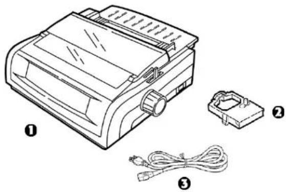
natural_image
Line drawing of a portable printer with three labeled components: cover, connector, and cable (no text or symbols present)1 Remove any packing tape, then grasp the tabs (1) at either end of the access cover and pivot it toward the front of the printer as far as it will go.
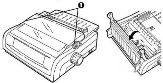
natural_image
Technical line drawing of a printer with a close-up view showing internal components (no text or symbols)2 Remove the printhead shipping restraint.
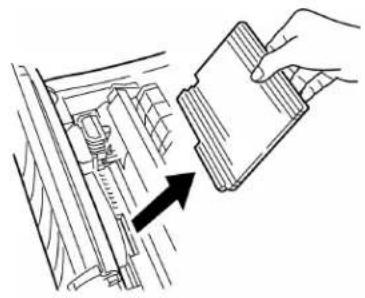
natural_image
Line drawing of a hand holding a document with an arrow pointing to a mechanical component (no text or symbols present)3 Remove the shipping restraint from the pull-up roller assembly (1).
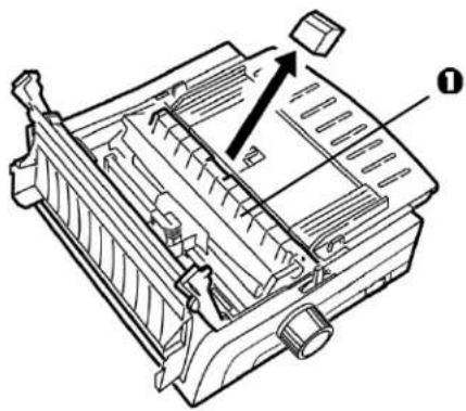
natural_image
Technical line drawing of a mechanical component with no visible text or symbols4 Use the tabs (1) to lift and remove the sheet guide, then remove the shipping restraint.
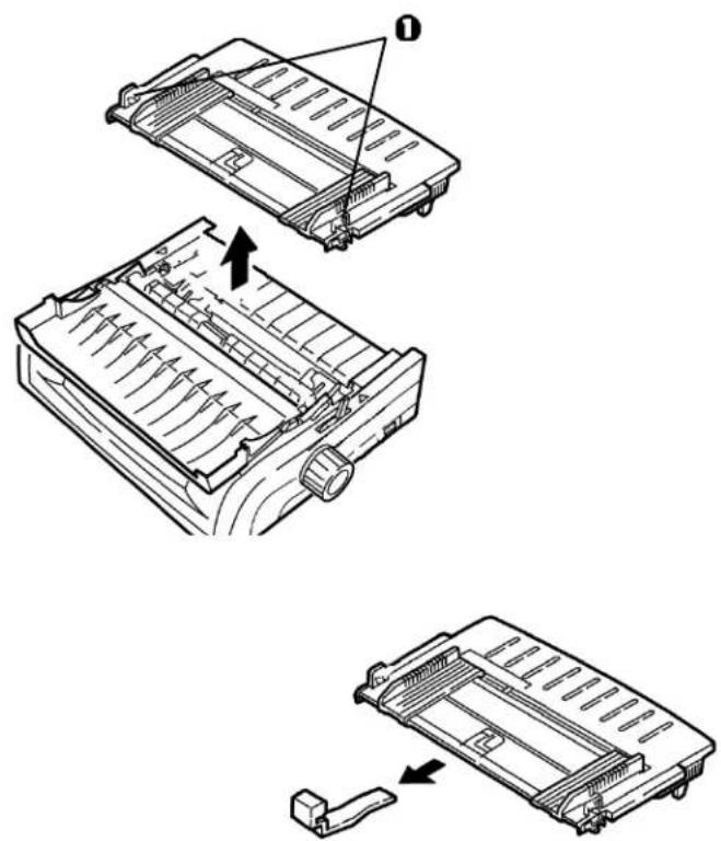
text_image
Technical diagram showing three-step assembly of a mechanical component with labeled parts and directional arrows indicating motion.5 Reinstall the sheet guide: insert the clips on either side of the separator into the notches marked with a triangle, then press down to secure the separator in place.
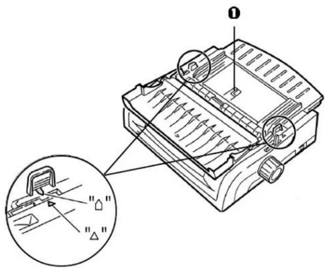
text_image
Technical diagram of a mechanical device with labeled parts and an inset view showing internal components.86 Microline 420/421 User's Guide
Install the Ribbon Cartridge
Important!
Make sure you have the correct replacement ribbon for your printer. The wrong ribbon will not print when installed in your printer.
Ribbon Cartridge Handling
- Leave unused ribbon cartridges in their packages until needed.
- Careful; the ribbon ink may cause permanent stains.
- Ribbon ink on skin or clothing can usually be removed with soap and water.
1 Make sure the printer is turned OFF.
2 Open the access cover and center the printhead (1).
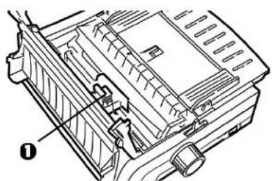
natural_image
Technical line drawing of a mechanical component with no visible text or symbolsCAUTION! The printhead may be HOT!
3 Unpack the new ribbon cartridge and install it on the printhead.
Important!
Do not remove the ribbon shield (1) from the ribbon!
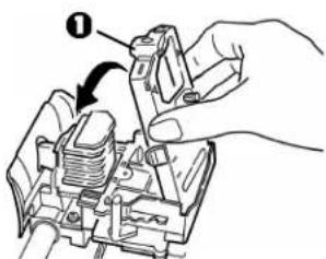
text_image
Diagram showing a hand adjusting a mechanical component with labeled parts and an arrow indicating direction4 Turn the take-up knob (1) in the direction of the molded-in arrow to take up any ribbon slack.
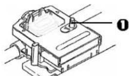
natural_image
Technical line drawing of a mechanical component with labeled part 0 (no text or symbols beyond label)5 Close the access cover and turn the printer on.
Power Connection
1 Make sure both the printer and the computer are OFF.
2 Plug the power cord into the back of the printer, then into a grounded outlet.
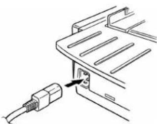
natural_image
Line drawing of a cable connector inserted into a vehicle chassis (no text or symbols)3 Turn on the printer.
Computer Connections
Parallel (LPT): IEEE 1284
- Requires bidirectional cable, max. length 6 ft. (1.8 m), not supplied.
• Printer has 36-pin socket
1 Make sure the printer and computer are both turned off.
2 Attach a suitable bidirectional cable to the parallel connector on the back of the printer. Then attach and secure the cable to your computer.
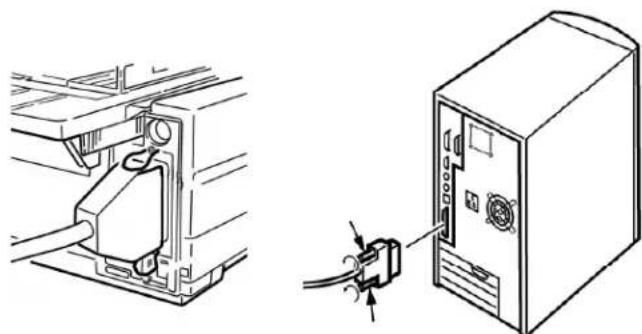
natural_image
Technical line drawing showing a cable connector inserted into a computer tower, with a close-up of the device's cable being inserted (no text or symbols present)3 Turn the printer and computer back on.
USB: Specification 1.1 Compliant
- Requires USB 1.1 cable, maximum length 19.7 ft. (5 m), not supplied.
- Printer has USB "B" receptacle.
1 Make sure the printer and computer are both turned off.
2 Attach a suitable USB cable to the printer. Then attach the cable to your computer.
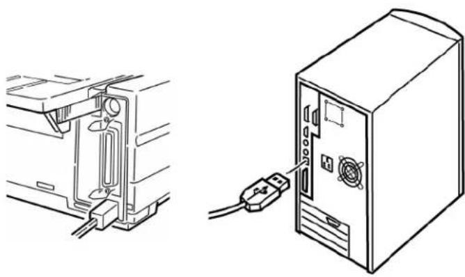
natural_image
Technical line drawing showing a computer setup with an open panel and a desktop tower connected to a USB cable (no text or symbols present)3 Turn the computer and printer back on.
Loading Paper
For instructions on loading paper, see "Loading Paper" in Chapter 5.
Testing the Printer
- Font Sample Test
- Rolling ASCII Test
- Hexadecimal Dump Mode
Font Sample Test
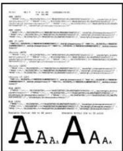
text_image
A A A A A A A A A A A A A A A A A A A A A A A A A A A A A A A A A A A A A A A A A A A A A A A A A A A A A A A A A A A A A A A A A A A A A A A A A A A A A A A A A A A A A A A A A A A A A A A A A A A A A A A A A A A A A A A A A A A A A A A A A A A A A A A A A A A A A A A A A A A A A A A AImportant!
Wide carriage Model ML421: If you are using 8.5" paper to run the tests, make sure the paper width selection in the printer menu is set to 8.5 inches. Otherwise, printing on the platen may damage the printer. See Chapter 4: Menu Mode for more information.
The Font Sample Test prints a sample of the fonts standard to the printer.
The top of the printout shows the Printer Model, Emulation, Country Code, Interface, and Firmware Revision Level.
1 Make sure paper is loaded.
2 Turn off the printer.
3 Press and hold the LF key while turning the printer back on. The printer prints a page of font samples and the test ends.
Rolling ASCII Test
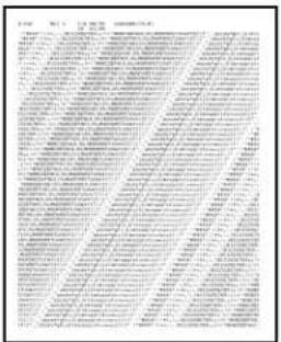
text_image
Scanned document with multiple columns of Chinese text, likely a form or report with structured content.Important!
Wide carriage Model ML421: If you are using 8.5" paper to run the tests, make sure the paper width selection in the printer menu is set to 8.5 inches. Otherwise, printing on the platen may damage the printer. See Chapter 4: Menu Mode for more information.
The Rolling ASCII Print Test produces a continuous printout of all 96 ASCII characters in a rolling pattern in whatever typeface is selected (default = LQ Courier).
The top of the printout shows the Printer Model, Emulation, Country Code, and Firmware Revision Level.
1 Make sure continuous forms paper is loaded.
2 Turn the printer off.
3 Press and hold the QUIET/TOF key while turning the printer back on. (If the printer comes on without starting the Rolling ASCII test print, you did not hold the QUIET/TOF key long enough.)
The printer prints the rolling ASCII text page after page.
4 Press SEL to end the test.
Hexadecimal Dump Mode
When the printer is placed in the Hexadecimal Dump Mode, all data received, including text and printer commands, is printed in both hexadecimal and ASCII format.
For example, the following line of BASIC code
LPRINT CHR\(27); "0"; CHR\ (30); "This is an example of a hexadecimal dump."
would print like this:

Note: In the ASCII format, all non-printable characters are represented by a period.
To engage the Hexadecimal Dump Mode:
1 Make sure paper is loaded.
2 Turn off the printer.
3 Hold the SEL and FF/LOAD keys for several seconds while turning on the printer.
To exit the Hexadecimal Dump Mode:
- Press the SEL key. or
- Turn the printer off, then on again.
92 Microline 420/421 User's Guide
Emulations
The factory default emulation for your printer is IBM Proprinter III.
If you wish to change to one of the other emulations, see “Changing Emulations” in Chapter 3.
Printer Drivers
The Oki driver for your printer is provided on the CD included with the printer. You can either load the Oki driver or select one of the compatible drivers listed below in your software application.
Loading the OKI Driver
Parallel Interface
1 Insert the CD into your CD-ROM drive.
Note: If the CD does not AutoPlay, click Start → Run → Browse, then browse to your CD-ROM drive, double-click Install.exe and click OK.
2 Select your printer model.
3 When the Menu Installer window appears, click the Printer Software button.
4 Follow the on-screen instructions.
USB Interface
1 Turn the printer on. The Windows Add New Hardware Wizard window displays.
2 Click Next.
3 Insert the CD into your CD-ROM drive.
4 Follow the on-screen instructions to install the software for your printer model.
Using a Compatible Driver
Note: See your software documentation for information on how to select a printer driver.
The drivers below are listed by decreasing compatibility with your printer. Use one as close to the top of the list as possible.
IBM Proprinter III
- IBM Proprinter III
- IBM Proprinter II
- IBM Proprinter
Epson FX
- Epson FX286e
- Epson FX 850/1050
- Epson FX 800/1000
Index
A
Accessories 68
Alignment problems ......9
ASCII Test 91
Auto Carriage return....35
Auto LF (Line Feed)....31, 35
Auto Select 32
B
Bar Codes 80
Bi-directional printing ....30, 40
Bottom Feed 81, 82
Form Tear-Off 29
Line Spacing 29
Skip Over Perforation ......29
Buffer
Clearing 38
Receive Buffer Size 78
C
Carbonless continuous forms .....81, 82
Card Stock 81, 82
Centering printhead position ....63
Character Pitch 39
Selecting 23
Character Set 28,36
Character Width....39
Characters Per Second (CPS) .....7
Code Page Character Set ....36
Codes, Printer Control ....69
Commands
Epson FX 72–74
IBM Proprinter III ......69–71
Oki Microline Standard .....75–77
Control Codes 69
Cut Sheet Feeder....68
E
Electrical Requirements......83
Emulations 24, 92
Mode 37
Envelopes 81, 82
Environmental Requirements 83
Epson FX Commands....72–74
F
Factory defaults, menu mode ......26
Font Sample Test 90
Fonts
Embedded Printer Commands ......62
Resident 80
Selecting 40
Forms Tear-Off 37
Changing....18
Top of Form 12, 17
Wait Time....41
Front Panel
Keys 9
Menu Mode......25
G
Graphics
Printing 30,37
Resolution 80
GROUP, Menu Mode ....25
H
Height, Double Height Printing......41
Hex Dump Mode 92
Humidity....83
|
I-Prime 32, 38, 61
IBM
Character Set....36
Proprinter III Commands....69–71
Initialization string....61
Interleaf Continuous Forms......82
Interleaf continuous forms....81
Interleaved 2 of 5....80
Italics 28,41
L
Labels 81, 82
Language 28
Length, Page
Rear Feed 29
Top Feed 30
Limited Operation ......9, 38, 65
Line Spacing ....38
Bottom Feed 29
Rear Feed 29
Top Feed 30
M
Margin, Bottom 30, 36
Mean Time Between Failures (MTBF) ..78
Mean Time to Repair (MTTR) .....78
Memory,Receive Buffer Size 78
MENU light 25
Menu Mode 25
Changing Settings 27
Entering 26
Exiting 26
Front Panel keys ......25
Printing the Menu Settings .....26
Reset to factory defaults .....26
Settings Table....28-42
0
Oki MICROLINE Standard
Commands....75–77
Operator Panel Function......65
Options 66
P
Page Length
Rear Feed 29
Top Feed 30
Page Width....39
Bottom Feed 29
Rear Feed 29
Setting in the Printer Menu......30, 39
Top Feed 30
Paper
Cut Sheet....68
Single Sheet 53
Static 65
Thickness 80
Weight....82
Widths 30, 39, 82
Paper Jams 64–66
Paper Lever....64
Paper Out 65
Override 30, 39
Paper Park....18
Paper Path, switching ....19
Parallel Interface....32
I-PRIME Signal 61
Parts, replacement, purchasing ....66
Perforation, skip over .....29, 41
Pitch, character ......28, 39
PlatenKnob part number......67
Postnet 80
Power rating....3
Print Method 78
Print Mode 28,40
Print Registration 31,40
Print Server Option.... 68
Print Size 79
Print Speed....7, 79
Print Suppress ....31, 40
Printer Control Codes 69-77
Printer Drivers, Selecting .....92–93
Printer Parameters ......25
Printhead....78
Gap....21
Proportional Spacing ......28, 40
Pull Tractor 68
Push Tractor....68
R
Rear Feed
Continuous Forms......10
Form Tear-Off 29,30
Jams, Repetitive ....56
Line Spacing 29
Paper Jam 55
Skip Over Perforation ......29
Receive Buffer Size 78
Reliability 78
Replacement Parts 66
Resolution (Graphics)...... 80
Ribbon Cartridge
Replacement Order No. 67
Replacing 42
Ribbon Shield ....43, 63, 87
Roll Paper Stand 68
RS-232C Serial Interface.... 78
S
Self Tests....90
Serial Interface....68
Serial Interface Option ......62
Server, Print Option ......68
Sheet Guide 67
Single Sheet Cut Sheet Feeder Option....68
Jams 58
Loading 53
Skip Over Perforation.... 29
Software Embedded commands....62
Matching drivers to emulations .....62
Software vs. printer settings ......61
Specifications 78
Standard Character Set ....28
Symbol Sets 28,38
T
Temperature Specifications ....83
Tests ASCII Test ....91
Font Sample Test 90
Hex Dump....92
Thickness, Paper......80
Time Out 32,41
Top Feed 81–84
Bottom Margin....30
Line Spacing 30
Pull Tractor 68
Single Sheet 11
Top of Form 35
Forms Tear-Off 8, 12, 17
Paper Shield 9,12
Reset to factory default.... 16
Setting 12
Standard Setting....12, 16
Typefaces 28
Selecting 40
U
Uni-directional printing, graphics .....30
Utility Front Panel Light ....80
Print Speeds 7
Utility Mode Print Quality ......22
W
Wait Time 30,41
Weight, Paper 82
Width Character....39
Double width printing....41
Page Bottom Feed....29 Rear Feed....29 Top Feed....30
Paper 82
Setting in the Printer Menu ....30, 39
Z
Zero character (slashed, unslashed).28, 41