Q11 - Security Camera ACTi - Free user manual and instructions
Find the device manual for free Q11 ACTi in PDF.


User questions about Q11 ACTi
0 question about this device. Answer the ones you know or ask your own.
Ask a new question about this device
Download the instructions for your Security Camera in PDF format for free! Find your manual Q11 - ACTi and take your electronic device back in hand. On this page are published all the documents necessary for the use of your device. Q11 by ACTi.
USER MANUAL Q11 ACTi
natural_image
Abstract geometric design with a red square and a five-pointed star-like shape (no text or symbols)Covert and Pinhole Covert Camera Series Hardware Manual
Q11, Q12, Q14, Q19, Q110, Q112
2016/04/11
Table of Contents
Precautions 4
Safety Instructions 6
Introduction 7
The List of Models 7
Package Contents......8
Physical Description 9
Mounting Solutions 11
Installing the Main Unit 12
Mounting on DIN Rail 12
Using the Bundled Mounting Rail 12
Installing the Camera Using the Flush Mount 13
Step 1: Install the Flush Mount.... 13
Step 2: Mount the Camera .... 15
Step 3: Route and Connect the Camera Cable....17
Step 4: Connect to the Network....18
Step 5: Access the Camera Live View....18
Cable Connections 19
Connecting a Power Adapter (Optional)....19
Connecting DI/DO Devices (Optional)....21
Connecting Audio In / Out Devices (Optional) 24
Connecting Serial Devices (Optional) 25
Other Accessories 26
How to Install / Remove the Memory Card 26
How to Insert the Memory Card 26
How to Remove the Memory Card....27
How to Shorten the Camera Cable 28
Accessing the Camera 31
Configure the IP Addresses....31
Access the Camera....35
Precautions
Read these instructions
Read all the safety and operating instructions before using this product.
Heed all warnings
Adhere to all the warnings on the product and in the instruction manual. Failure to follow the safety instructions given may directly endanger people, cause damage to the system or to other equipment.
Servicing
Do not attempt to service this product yourself as opening or removing covers may expose you to dangerous voltage or other hazards. Refer all servicing to qualified service personnel.
Trademarks
ACTi and ACTi logo are registered trademarks of ACTi Corporation. All other names and products used in this manual are registered trademarks of their respective companies.
Liability
Every reasonable care has been taken during the writing of this manual. Please inform your local office if you find any inaccuracies or omissions. ACTi will not be held responsible for any typographical or technical errors and reserves the right to make changes to the product and manuals without prior notice.
Federal Communications Commission Statement

This equipment has been tested and found to comply with the limits for a class B digital device, pursuant to Part 15 of the FCC Rules. These limits are designed to provide reasonable protection against harmful interference in a residential installation. This equipment generates, uses, and can radiate radio frequency energy and, if not installed and used in accordance with the instructions, may cause harmful interference to radio communications. However, there is no guarantee that interference will not occur in a particular installation. If this equipment does cause harmful interference to radio or television reception, which can be determined by turning the equipment off and on, the user is encouraged to try to correct the interference by one or more of the following measures:
- Reorient or relocate the receiving antenna.
- Increase the separation between the equipment and receiver.
- Connect the equipment into an outlet on a circuit different from that to which the receiver is connected.
- Consult the dealer or an experienced radio/TV technician for help.
Warning: Changes or modifications to the equipment that are not expressly approved by the responsible party for compliance could void the user's authority to operate the equipment.
European Community Compliance Statement

This product has been tested and found to comply with the limits for Class B Information Technology Equipment according to European Standard EN 55022
and EN 55024. In a domestic environment, this product may cause radio interference in which cause the user may be required to take adequate measures.
Safety Instructions
Cleaning
Disconnect this product from the power supply before cleaning.
Accessories and Repair Parts
Use only the accessories and repair parts recommended by the manufacturer. Using other attachments not recommended by the manufacturer may cause hazards.
Installation
Do not use the device near water, for example, in a web basement or near a swimming pool and the likes. Install the device (such as PoE injector, alarm, etc.) that will be used with the camera in a dry place protected from weather.
Servicing
Do not attempt to service this product yourself. Refer all servicing to qualified service personnel.
Damage Requiring service
Disconnect this product from the power supply immediately and refer servicing to qualified service personnel under the following conditions.
1) When the power-supply cord or plug is damaged
2) If liquid has been spilled, or objects have fallen into the product.
3) If the inner parts of product have been directly exposed to rain or water.
4) If the product does not operate normally even by following the operating instructions in this manual. Adjust only those controls that are covered by the instruction manual, as improper adjustment of other controls may result in damage, and will often require extensive work by a qualified technician to restore the product to its normal operation.
Safety Check
Upon completion of any service or repairs to this product, ask the service technician to perform safety checks to determine if the product is in proper operating condition.
Introduction
The List of Models
This hardware manual contains the following models:
| Q11 | 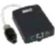 | 2MP Indoor Covert with Basic WDR, SLLS, Fixed lens, f3.6mm/F1.85 |
| Q12 | 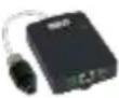 | 2MP Indoor Covert with Basic WDR, SLLS, Fixed lens, f2.55mm/F2.2 |
| Q14 | 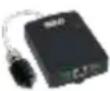 | 2MP Indoor Pinhole Covert with Basic WDR, SLLS, Fixed lens, f3.7mm/F2.5 |
| Q19 | 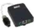 | 5MP Indoor Covert with Basic WDR, Fixed lens, f2.93mm/F2.0 |
| Q110 |  | 5MP Indoor Covert with Basic WDR, Fixed lens, f1.9mm/F2.8 |
| Q112 |  | 5MP Indoor Pinhole Covert with Basic WDR, Fixed lens, f3.7mm/F2.5 |
Package Contents
Check if the camera package comes with the following items.
| Camera (Lens vary per model) | Main Unit | Mounting Rail |
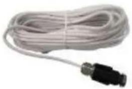 | 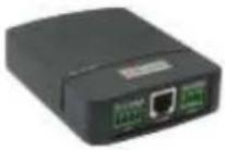 | 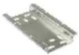 |
| Terminal Block (for Power) | Terminal Block (for DI/DO) | Terminal Block (for Audio In/Out) |
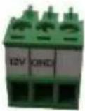 | 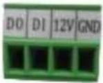 | 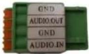 |
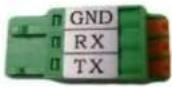
| Terminal Block (for RS-232) | Quick Installation Guide | Warranty Card |
 |  |  |
Mounting Accessories
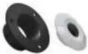
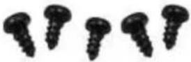
| Flush Mount | Rubber(for Pinhole Covert only) | Camera Set Screw |
 |  |  |
| Flush Mount &Mounting Rail Screws | Drill Template | |
 |  | |
Physical Description
text_image
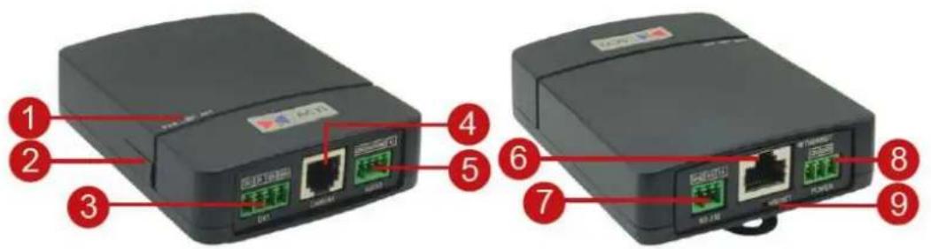
Diagram of two network device ports with labeled ports and connectors, numbered 1 to 9 for identification.| Item | Description | |
| 1 | LED Indicators | Power LED (PWR): Lights BLUE to indicate power is connected.Link LED (LINK): Lights GREEN to indicate network is connected.Activity LED (ACT) : Flashes AMBER to indicate network activity is in progress. |
| 2 | Memory Card Slot | Insert a memory card (not included) into the slot for local recording purposes. SeeHow to Install / Remove the Memory Cardon page 26 for more information.NOTE:Supports only microSDHC and microSDXC cards. |
| 3 | Digital Input / Output | Connects to digital input or output devices, such as an alarm trigger, panic button, etc. Digital Input (DI) and Digital Output (DO) devices are used in applications like motion detection, event triggering, alarm notifications, etc. SeeConnecting DI/DO Devices (Optional) on page 21 for information. |
| 4 | Camera Port | Connects the camera. |
| 5 | Audio Input / Output | Connects to audio input and output devices, such as microphones and speakers. SeeConnecting Audio In / Out Devices (Optional) on page 24 for more information. |
| 6 | Ethernet Port | Connects to a network using an Ethernet cable. |
| 7 | Serial Port | Connects to serial device using the RS-232 protocol. SeeConnecting Serial Devices (Optional) on page 25 for more information. |
| 8 | DC 12V Power Input | In case the camera is connected to a non-PoE (Power over Ethernet) switch, use this connector to connect the camera to an external power adapter. SeeConnecting a Power Adapter (Optional) on page 19 for more information. |
| 9 | Reset Button | Restores the factory default settings of the camera. To reset the camera, while the power is on, press and hold the Reset Button for at least 5 seconds or until the Power LED goes off. |
Mounting Solutions
There are several mounting options that you can use to install the camera. Select the most suitable solution for your installation environment.
| Mount Types | Accessories |
| Flush Mount | Use the bundled flush mount to install the camera behind the surface of wall or ceiling. Only the lens can be seen outside the surface. SeeInstalling the Camera Using the Flush Mounton page 13. |
| Tiltable Flush Mount | Suitable if the camera is required to be tilted to acquire the desired viewing angle when mounted on high walls or ceiling. The tiltable flush mount is available for purchase. Installation procedures are covered in the Installation Guide downloadable from the website (http://www.acti.com/mountingselector). |
| Bracket Mount | Suitable for mounting on a hard surface, such as an enclosure or ceiling or wall made from cement, wood, or metal. Common application will be inside an ATM machine. The bracket is available for purchase. Installation procedures are covered in the Installation Guide downloadable from the website (http://www.acti.com/mountingselector). |
| Corner Mount | Suitable when mounting the camera on corner walls, like an elevator, hallway, etc. The camera is tilted 20^ to capture a larger viewing angle below the camera and less on the ceiling. The corner mount is available for purchase. Installation procedures are covered in the Installation Guide downloadable from the website (http://www.acti.com/mountingselector). |
NOTE:
- For more information about the mounting solutions and accessories, please check the Mounting Accessory Selector in our website (http://www.acti.com/mountingselector).
Installing the Main Unit
The main unit can be directly mounted on a DIN rail or use the bundled mounting rail for flexible installations. Before installation, determine the location to mount the camera and the main unit. Consider that the camera cable is 12 meters long. The main unit can be installed apart from where the camera is mounted, like in a secured area or separate room.
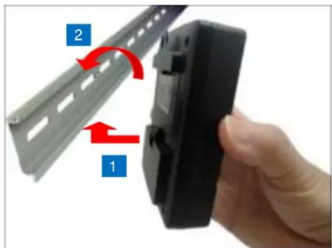
Mounting on DIN Rail
- Attach the lower end of the main unit to the DIN rail.
- Slightly push up the main unit and snap the upper end into place.
natural_image
Hand holding a black plastic clip attached to a metal rack, with red arrows indicating rotation (no text or symbols)Using the Bundled Mounting Rail
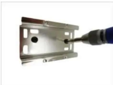
- Install the mounting rail on the surface using the two (2) screws.
natural_image
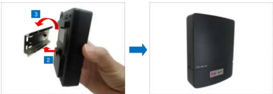
Close-up of a metal screwdriver inserted into a metal bracket component (no text or symbols visible)- Attach the lower end of the main unit to the mounting rail.
- Slightly push up the main unit and snap the upper end into place.
text_image
Instructional image showing a hand holding a device with labeled parts and a close-up of its device, indicating assembly or repair.Installing the Camera Using the Flush Mount
This section describes the procedures in mounting the covert or pinhole covert camera on a flat surface, such as wall or ceiling, with the use of the bundled flush mount. This installation requires access to the back of the surface. The main unit can be installed apart from where the camera is mounted, like in a secured area or separate room.
NOTE: The following pictures are for reference only, actual lens differs depending on the camera model.
Before installation, consider the following:
- Requires access to the back of the surface
• Supported surface thickness: 1 \~ 10 mm
• Camera cable length: 12 meters - Mounting location of camera and the main unit can be separate
Step 1: Install the Flush Mount
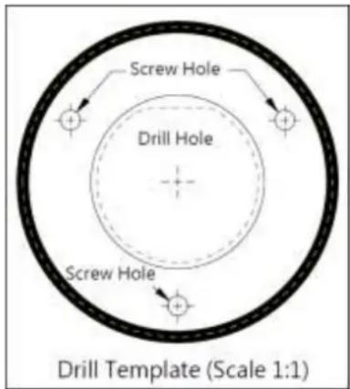
- Attach the bundled Flush Mount drill template sticker on the target installation surface.
- Mark the screw holes and the perimeter where to mount the flush mount.
- Drill the lens hole.
text_image
Screw Hole Drill Hole Screw Hole Drill Template (Scale 1:1)-
After drilling the lens hole, remove the drill template.
-
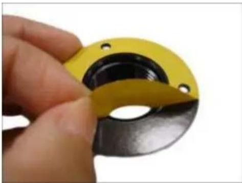
Peel off the sticker from the flush mount.
natural_image
Close-up of a hand holding a yellow and black mechanical component (no text or symbols visible)- Attach the flush mount to the surface according to the marked area where the two (2) set screw holes should either face up or down.
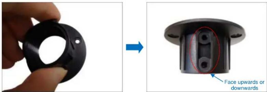
text_image
Face upwards or downwards- The adhesive on the flush mount is sufficient to hold the mount against most types of surfaces. Nevertheless, three (3) screws are bundled with the camera package that can be used to secure the flush mount. Use the screws as needed.
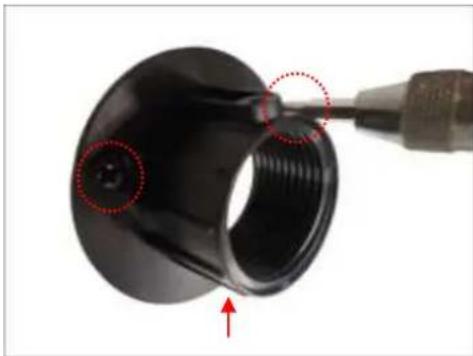
natural_image
Close-up of a black mechanical component with red dotted circles highlighting a feature, and a red arrow pointing to a detail (no text or symbols visible)Step 2: Mount the Camera
- Screw the camera to the flush mount. The depth of installing the camera through the flush mount varies on the thickness of the wall.
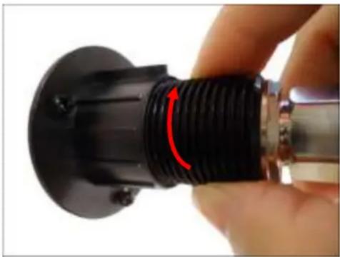
natural_image
Close-up of a hand holding a black plastic connector with a red arrow indicating rotation (no text or symbols visible)- When the correct depth is reached, make sure the flat area on the lens module is aligned with the set screw holes (either upward or downward). The flat area indicates the correct viewing orientation of the camera.

natural_image
Close-up of a black threaded connector with a red arrow pointing to its tip, attached to a white cable (no text or symbols visible)- Attach the set screw to one of the holes on the flush mount to fix the depth of the lens position.
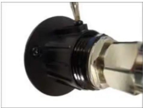
natural_image
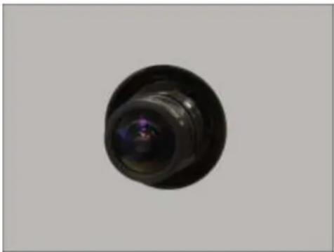
Close-up of a mechanical component with a black circular base and metallic shaft (no visible text or symbols)Meanwhile, the installation on the other side of the surface will only show the camera lens. Example image below:
natural_image
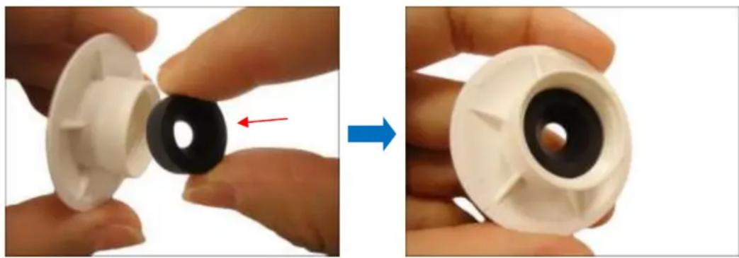
Close-up of a black circular object with a lens-like cutout, isolated on a plain gray background (no text or symbols visible)- For pinhole covert models, insert the rubber into the top cover. Skip this step for non-pinhole covert models.
natural_image
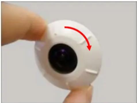
Two hands holding a white plastic component, one showing a black hole and the other showing a black hole with red arrow (no text or symbols)- Attach the top cover to the lens module to complete the installation.
natural_image
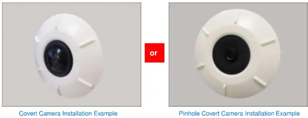
Close-up of a white spherical object with a black center and red curved arrow indicating rotation (no text or symbols)Final installation examples below:
Step 3: Route and Connect the Camera Cable
The camera cable is 12 meters long. This allows the camera and the main unit to be installed apart, such as in a separate area or room, etc.
- The main unit should be mounted at this point, if not, install the main unit, see Installing the Main Unit on page 12 for details.
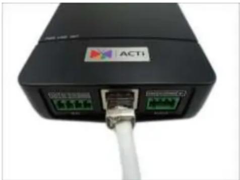
- Route the camera cable towards the main unit accordingly. Probably along the surface or may pass through a hole on the surface and towards the main unit.
- Connect the camera cable connector to the Camera port of the main unit.
natural_image
Close-up of a black ACTi network switch with visible ports and a white cable (no text or symbols on the device body)Step 4: Connect to the Network
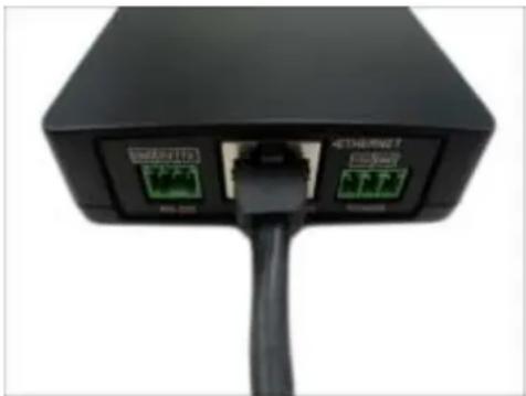
- Connect one end of a network cable to the Ethernet port of the main unit.
natural_image
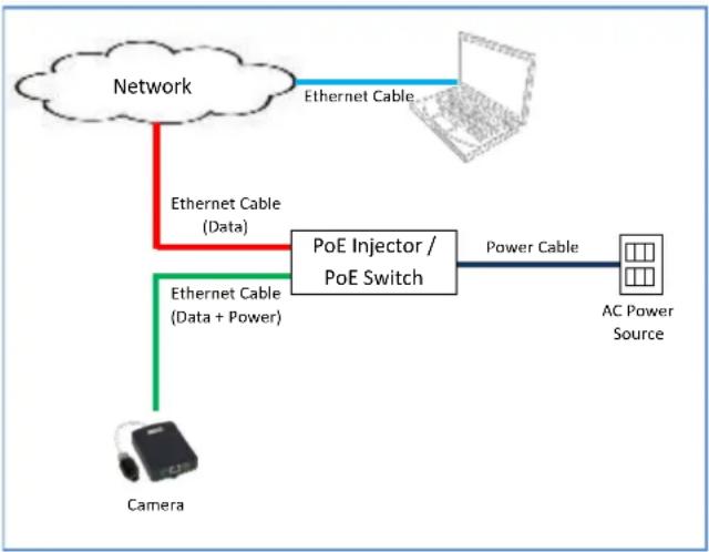
Close-up of a black USB port with two green Ethernet ports and a black cable (no visible text or symbols)- Connect the other end to a switch or injector. Then, connect the switch or injector to a network or PC and a power source. See Power-over-Ethernet (PoE) example connection diagram below.
flowchart
graph TD
    A["Network"] -->|Ethernet Cable (Data)| B["PoE Injector / PoE Switch"]
    B -->|Power Cable| C["AC Power Source"]
    B -->|Ethernet Cable (Data + Power)| D["Camera"]
    D -->|Ethernet Cable| A
In case of using a non-PoE switch, power up the camera using a power adapter (not supplied). See Connecting a Power Adapter (Optional) on page 19 for more information.
- As needed, connect and power up other devices, such as digital input/output, audio, or serial device. See Cable Connections on page 19 for more information on connecting other devices.
Step 5: Access the Camera Live View
See Accessing the Camera on page 31 for more information.
Cable Connections
This section describes the procedures in preparing the external devices that you can connect to the camera. The camera main unit supports DC12V power input, Digital Input and Output (DI/DO), Audio Input and Output, and Serial devices using the bundled terminal blocks. The use of these devices, however, is optional.
Connecting a Power Adapter (Optional)
The camera can be powered by a Power over Ethernet (PoE) switch that is IEEE802.3af compliant. In case of using a non-PoE switch or your PoE switch has limited power supply, you can purchase a power adapter and directly connect the camera to a power outlet. The power adapter must be connected to the supplied terminal block before use.
To do this, follow the procedures below:
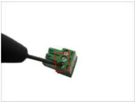
- Loosen the screws of the 12V and GND pins of the power terminal block.
natural_image
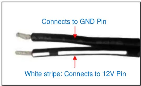
Close-up of a green electrical connector being inserted with a black tool (no text or symbols visible)- Take note that a standard power adapter cable has two (2) different wires:
text_image
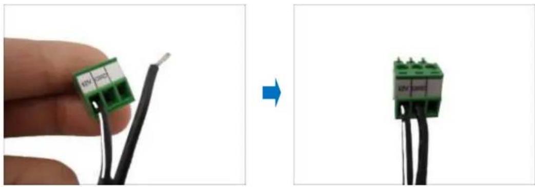
Connects to GND Pin White stripe: Connects to 12V Pin- Connect the wire with the white stripe to the 12V pin and the other to the GND pin.
natural_image
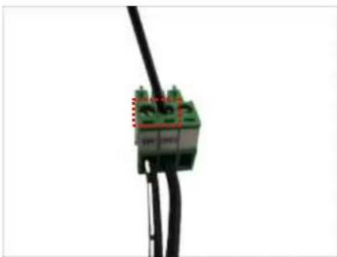
Two-step diagram showing a hand holding a green terminal block connected to black wires, before and after transformation (no text or symbols)- Tighten the screws of the 12V pin and the GND pins to secure the wire connection.
natural_image
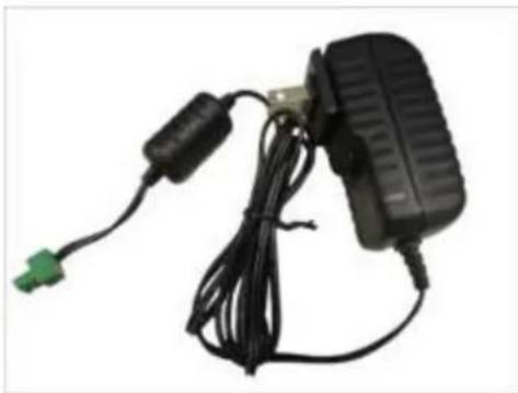
Close-up of a green electrical connector with red dashed lines indicating connection points (no text or symbols visible)- Set the prepared power adapter for connection later. Below is an example of a power adapter with an attached terminal block.
natural_image
Black electronic device with attached cable and connector, no visible text or symbolsNOTE: The power adapter is not bundled in the package.
Connecting DI/DO Devices (Optional)
Depending on your surveillance needs, you may connect one (1) digital input and one (1) digital output device to the main unit to trigger events or notifications.
Digital Input (DI) devices can be used to notify the camera about an activity in the camera site. DI can be triggers of events. For example, you can connect a “panic button” to the camera; as such when the panic button is pressed, the alarm signal will be sent through the camera. Other common DI device applications are emergency button, smoke detector, passive infrared sensor, etc.
Digital Output (DO) devices are external devices that are activated by the camera upon an event inside the camera. For example, you can connect an “alarm horn” to the camera; as such when an event occurs inside the camera (e.g. detected intruder), the alarm horn will sound. Other common DO device applications are motion-triggered lights, electric fence, magnetic door locks, etc.
- Loosen the screws on the terminal block.
- Connect the input/output pins to the corresponding pins on the terminal block, see mapping table below.
- Tighten the screws on the terminal block when done.
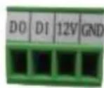
To connect an input device (DI), map the pins as below:
| Device | Pin | Mapping Instructions |
| Digital Input (DI) | GND | Connect the wires of the digital input device to GND and DI. |
| DI |
To connect an output device (DO), map the pins as below:
| Device | Pin | Mapping Instructions |
| Digital Output (DO) | 12V | Connect the wires of the digital output device to 12V and DO. |
| DO |
The table below shows the DI/DO connection specifications:
| Device | |||
| DI | Connection design | TTL - compatible logic levels | |
| Voltage | To trigger (low) | Logic level 0: 0V ~ 0.4V | |
| Normal (high) | Logic level 1: 3.1V ~ 30V | ||
| Current | 10mA ~ 100mA | ||
| DO | Connection design | Transistor (Open Collector) | |
| Voltage & Current | < 24V DC, < 50mA | ||
Typical Connection
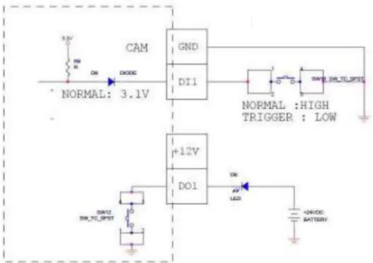
Based on these specifications, if the DI device has a voltage of 0V \~ 30V or the DO device has a voltage of < 24V (<50mA), then the camera can supply internal power to these devices and there is no need to connect the DI/DO device to an external power source.
In this case, wire connection to GND and DI pins to connect a DI device and use the 12V and DO pins to connect a DO device. See wiring scheme below:
text_image
CAM GND DI1 NORMAL: 3.1V +12V DOI DAYU SW_TC_SPDT ON LED NORMAL : HIGH TRIGGER : LOW +DIVDC BATTERYHigh Voltage DO Device Connection
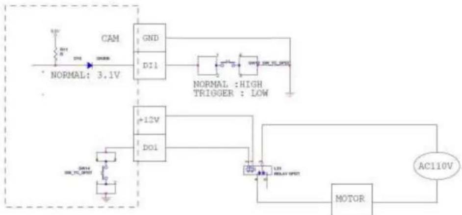
Even though the camera provides 12V power, this may not be enough for some high voltage DO devices, such as a ceiling light or a motor that opens or closes a gate. In this case, there is a need to connect an external relay. See wiring scheme below:
flowchart
graph TD
    A[" Kam "] --> B[" GND "]
    B --> C[" D11 "]
    C --> D[" NORMAL : HIGH TRIGGER : LOW "]
    E[" NORMAL: 3.1V "] --> F[" +12V "]
    F --> G[" DOI "]
    G --> H[" MOTOR "]
    H --> I[" AC110V "]
    J[" SOUT 3.1V"] --> K[" SOUT 3.1V"]
    L[" SOUT 3.1V"] --> M[" SOUT 3.1V"]
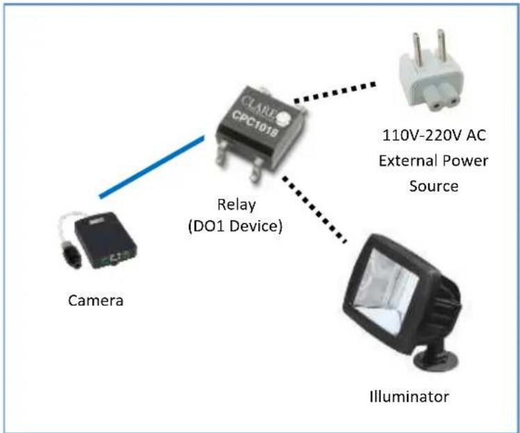
Note that when choosing an appropriate relay, please refer to its specifications and make sure they match the above design. The triggering circuit voltage has to be around 12V DC and the switch-controlled circuit voltage has to match the external power supply (e.g. 110V AC or 220V AC).
The illustration below is a graphic example of connecting a relay to a high voltage DO device.
text_image
CAMBR CPC101B Relay (DO1 Device) Camera 110V-220V AC External Power Source IlluminatorNOTE: For more information on DI/DO connections, please refer to the Knowledge Base article All About Digital Input and Digital Output downloadable from the link below (http://Download.acti.com?id=516).
Connecting Audio In / Out Devices (Optional)
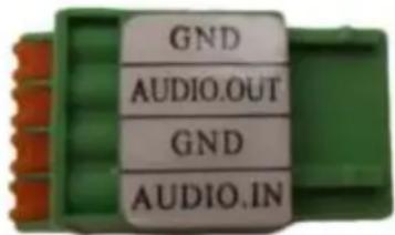
Depending on your surveillance needs, you may connect audio input or output device, such as an active microphone or speaker, to the main unit. In this case, you need to connect the audio input/output device to the supplied audio terminal block.
text_image
GND AUDIO.OUT GND AUDIO.INTo connect audio input / output devices, map the pins to one of the pin combinations below:
| Device | Pin | Mapping Instructions |
| Audio Output | GND | Connect the wires of the audio output device to GND and AUDIO.OUT. |
| AUDIO.OUT | ||
| Audio Input | GND | Connect the wires of the audio input device to GND and AUDIO.IN. |
| AUDIO.IN |
Press and hold the orange tab as you insert the wire through the pin slot, then release the orange tab to secure the wire.
NOTE: For more information about AUDIO in connections, please refer to the Knowledge Base article How to Use Audio-in of ACTi Cameras. downloadable from the link below (http://Download.acti.com?id=534).
Connecting Serial Devices (Optional)
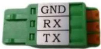
Depending on your needs, you may connect a serial device to the main unit. In this case, you need to connect the serial device to the supplied RS-232 terminal block.
text_image
GND RX TXTo connect a serial device, map the pins as below:
| Terminal Block | Wire Mapping | |
| Pin Number / Label | Main Unit | Serial Device |
| TX | TX | RX |
| RX | RX | TX |
| GND | Ground pin | |
Press and hold the orange tab as you insert the wire through the pin slot, then release the orange tab to secure the wire.
Other Accessories
How to Install / Remove the Memory Card
The camera supports local video recording to a memory card (not supplied).
NOTE: Supports microSDHC and microSDXC cards.
How to Insert the Memory Card
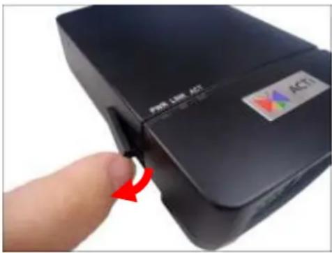
- Open the memory card slot cover.
natural_image
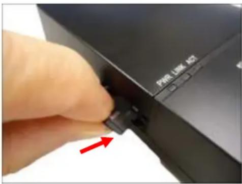
Close-up of a black electronic device with a red arrow pointing to a button, no visible text or symbols on the device itself.- Insert the memory card with the metal contacts facing down the main unit.
text_image
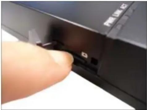
PHR LINK AG- Push the card until it clicks into place.
natural_image
Close-up of a finger pressing a black button on a device (no visible text or symbols)Once inserted, make sure to access the camera Web Configurator and "mount" the card to prepare the card for local recording. Refer to the camera Firmware User's Manual for more information.
How to Remove the Memory Card
In case there is a need to remove the card, make sure to access the camera Web Configurator to safely “unmount” the card first (see the camera Firmware User’s Manual for more information). Once unmounted from the firmware, push the card to eject it from the slot.
How to Shorten the Camera Cable
In case the camera cable is too long for the application environment, follow the procedures below to shorten the cable.
- Prepare the following tools:
• RJ-12 Connector (with shielding is recommended)
- RJ-12 Crimping Tool
- Scissors
- Unsnap the ferrite core from the camera cable, and set it aside for later use.
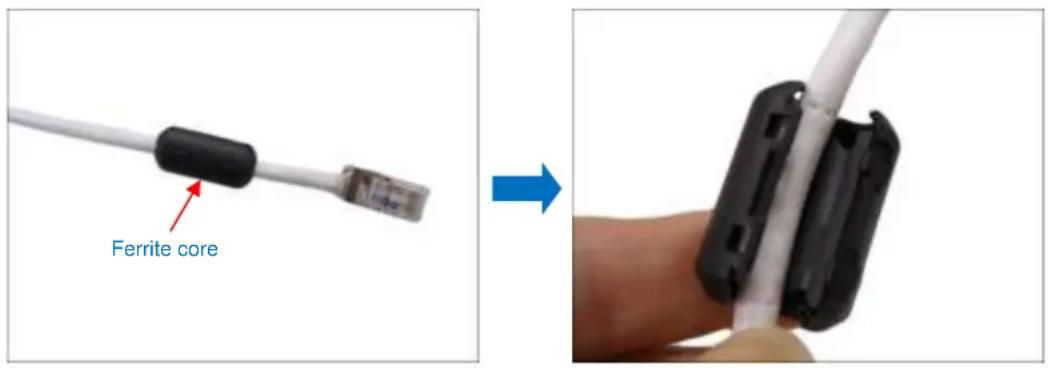
text_image
Ferrite core- Measuring from the camera end, cut the cable according to desired length.
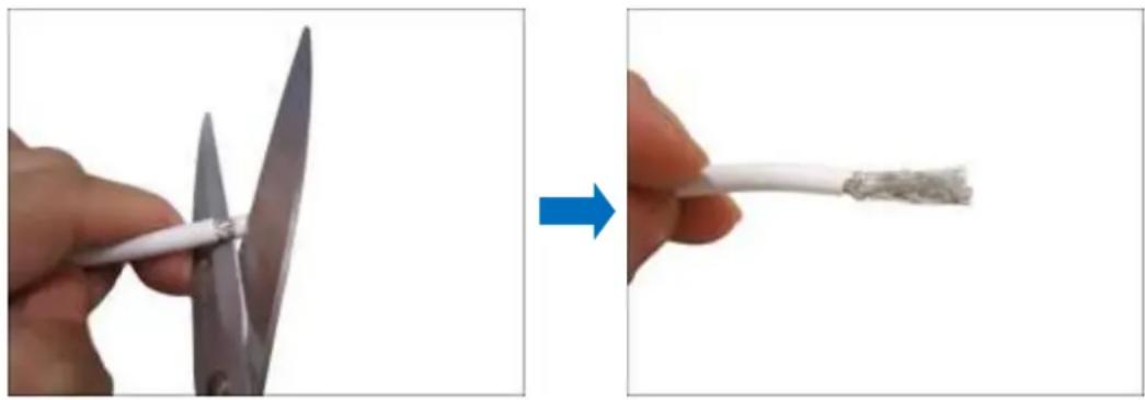
- Strip about 10 mm of the plastic coating at the end of the cable.
natural_image
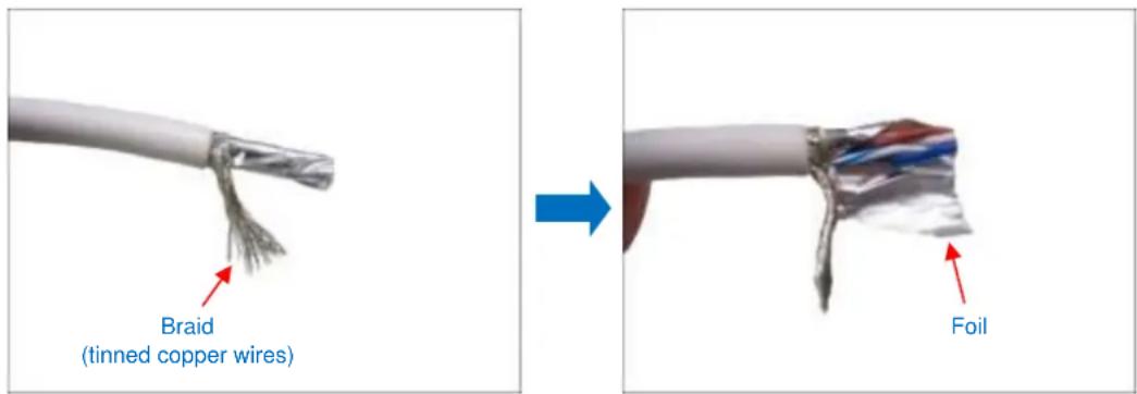
Two-step illustration showing a hand holding scissors and a white cable being cut (no text or symbols)- Twist the braid or tinned copper wires together and remove the foil coating.
text_image
Braid (tinned copper wires) Foil- Unwind the wires and arrange them according to the color sequence below.
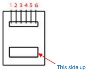
text_image
1 2 3 4 5 6 This side up| 1 | Brown |
| 2 | Stripe Brown |
| 3 | Unused |
| 4 | Unused |
| 5 | Stripe Blue |
| 6 | Blue |
- Push the wires into the connector all the way to the end.
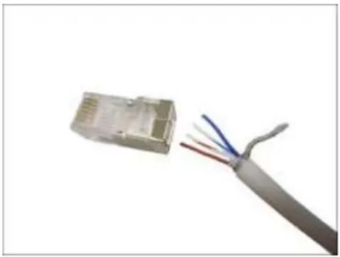
natural_image
Close-up of a gray cable with three colored wires attached to a white rectangular connector (no text or symbols visible)- Place the connector into the crimping tool, and cinch down to secure the RJ-12 connector to the cable.
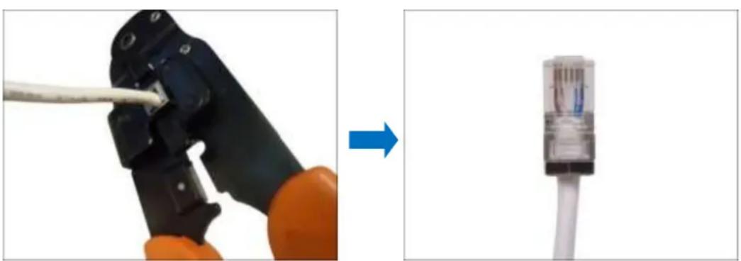
natural_image
Two-step diagram showing a wire being inserted into a black crimping tool and then connected to a white cable via a connector (no text or symbols present)NOTE: If the RJ-12 connector has metal shielding, solder the braid on the connector shielding.
- Snap the ferrite core back to the cable with a distance of 30 mm from the cable connector.
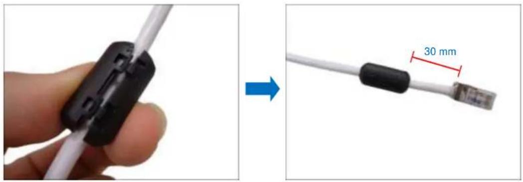
text_image
30 mmNOTE: The ferrite core is used to suppress electromagnetic interference (EMI) from the camera that may affect other devices, as well as prevent the EMI from other electronic devices to affect the performance of the camera.
Accessing the Camera
Configure the IP Addresses
In order to be able to communicate with the camera from your PC, both the camera and the PC have to be within the same network segment. In most cases, it means that they both should have very similar IP addresses, where only the last number of the IP address is different from each other. There are 2 different approaches to IP Address management in Local Area Networks – by DHCP Server or Manually.
Using DHCP server to assign IP addresses
If you have connected the computer and the camera into the network that has a DHCP server running, then you do not need to configure the IP addresses at all – both the camera and the PC would request a unique IP address from the DHCP server automatically. In such case, the camera will immediately be ready for the access from the PC. The user, however, might not know the IP address of the camera yet. It is necessary to know the IP address of the camera in order to access it using a Web browser.
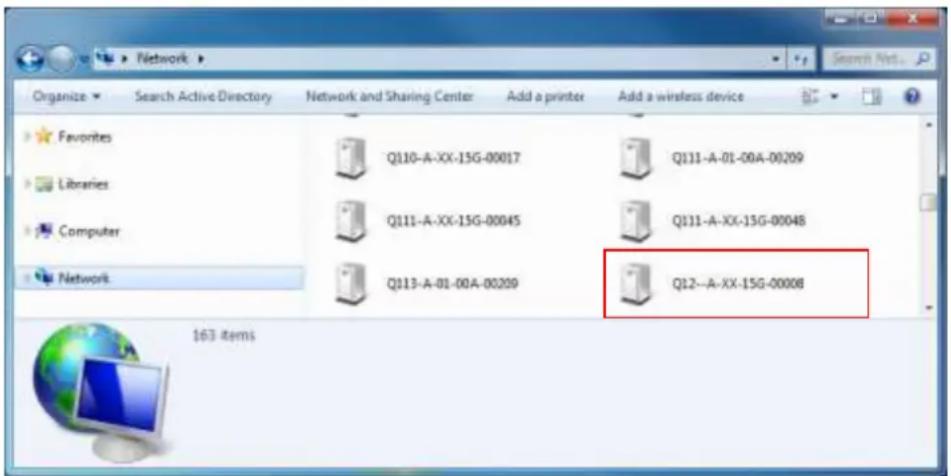
The quickest way to discover the cameras in the network is to use the simplest network search, built in the Windows system – just by pressing the “Network” icon, all the cameras of the local area network will be discovered by Windows, thanks to the UPnP function support of our cameras.
In the example below, the camera that has just been connected to the network is successfully found.
text_image
Network Organize Search Active Directory Network and Sharing Center Add a printer Add a wireless device Favorites Q110-A-XX-15G-00017 Q111-A-01-00A-00209 Libraries Q111-A-XX-15G-00045 Q111-A-XX-15G-00048 Computer Q113-A-01-00A-00209 Q12--A-XX-15G-00008 Network 163 itemsDouble-click the mouse on the camera model name, the default browser of the PC is automatically launched and the IP address of the target camera is already filled in the address bar of the browser.
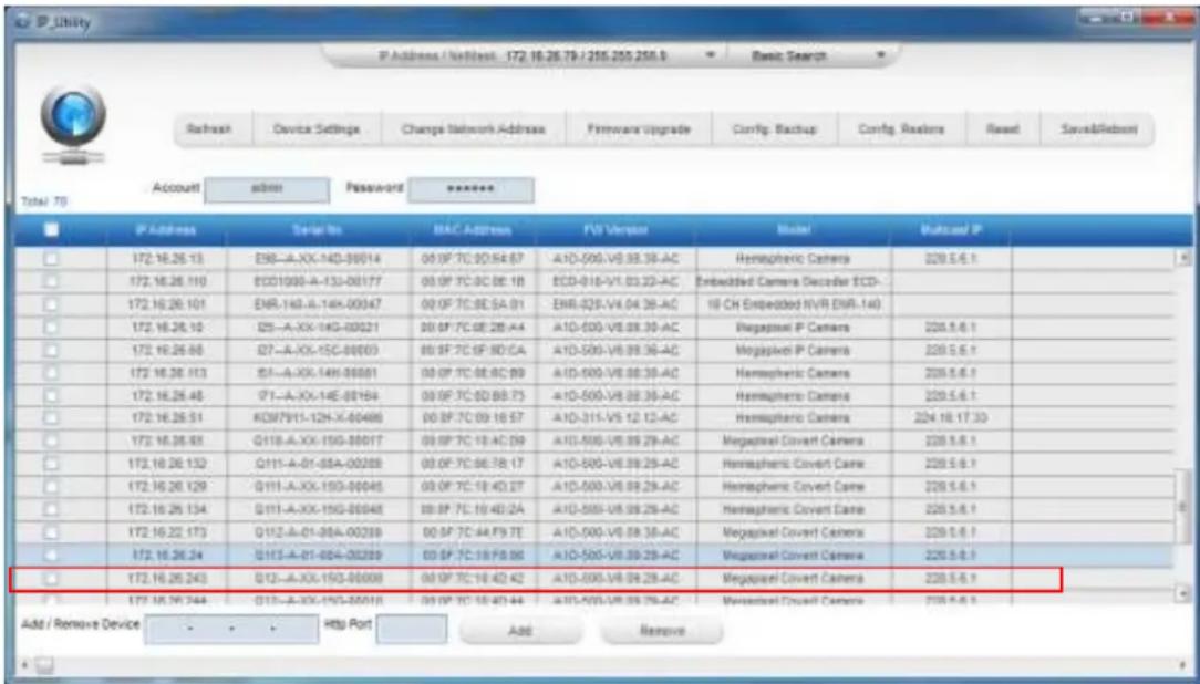
If you work with our cameras regularly, then there is even a better way to discover the cameras in the network – by using IP Utility. The IP Utility is a light software tool that can not only discover the cameras, but also list lots of valuable information, such as IP and MAC addresses, serial numbers, firmware versions, etc, and allows quick configuration of multiple devices at the same time.
Search and download IP Utility for free from http://www.acti.com/DownloadCenter.
When you launch IP Utility, the list of connected cameras in the network will be shown. See sample illustration below:
text_image
P_Utility P Address / WebHost: 172.16.26.79 / 255.255.258.5 Basic Search Refresh Device Settings Change Network Address Firmware Upgrade Config Backup Config Reuters Reset Save&Redo Total: 70 Account submit Password ****** P Address Serial No MAC Address FV Version Master Multicel P 172.16.26.13 E98-A.XX-14D-00014 00:0F TC 00:04:07 A1D-505-V8:08:38-AC Hemaphenic Camera 220.5.6.1 172.16.26.110 E001000-A-153-00177 00:0F TC 0C 0E:1B ECD-016-V1.03:33-AC Embedded Camera Decoder ECD- 172.16.26.101 ENR-140-A-14K-00047 00:0F TC 0E:SA:01 ENR-025-V4:04:38-AC 10 CH Embedded NVR ENR-140 172.16.26.10 I25-A.XX-14G-00021 00:0F TC 08:28:4A A1D-505-V8:08:39-AC Megapixel P Camera 220.5.6.1 172.16.26.68 I27-A.XX-15C-00003 00:0F TC 0F:8C/CA A1D-505-V8:09:36-AC Megapixel P Camera 220.5.6.1 172.16.26.113 I51-A.XX-14H-00001 00:0F TC 08:6C:89 A1D-505-V8:08:39-AC Hemaphenic Camera 220.5.6.1 172.16.26.48 I71-A.XX-14E-00164 00:0F TC 0D:8B:73 A1D-505-V8:08:39-AC Hemaphenic Camera 220.5.6.1 172.16.26.51 KDM7911-12H-X-60486 00:0F TC 09:16:57 A1D-311-V5:12:12-AC Hemaphenic Camera 224.18.17:33 172.16.26.83 Q11B-A.XX-15G-88017 00:0F TC 1B:4C:39 A1D-505-V8:09:29-AC Megapixel Coveri Camera 220.5.6.1 172.16.26.132 Q11I-A-01-88A-00288 00:0F TC 06:7B:17 A1D-505-V8:09:29-AC Hemaphenic Coveri Camera 220.5.6.1 172.16.26.129 Q11I-A.XX-15G-99445 00:0F TC 1B:4D:2T A1D-505-V8:09:29-AC Hemaphenic Coveri Camera 220.5.6.1 172.16.26.134 Q11I-A.XX-15G-99448 00:0F TC 1B:4D:2A A1D-505-V8:09:29-AC Hemaphenic Coveri Camera 220.5.6.1 172.16.22.173 Q11Z-A-01-98A-00289 00:5F TC 4A:F9:7E A1D-505-V8:09:38-AC Megapixel Coveri Camera 220.5.6.1 172.16.26.34 Q11Z-A-01-98A-00289 03:5F TC 3B:F8:8E A1D-505-V8:09:29-AC Megapixel Coveri Camera 220.5.6.1 172.16.26.243 Q12-A.XX-15G-99998 00:5F TC 1B:4D:4Z A1D-505-V8:09:29-AC Megapixel Coveri Camera 220.5.6.1 172.16.26.244 Q13-A.XX-15G-99999 03:5F TC 1B:4D:4A A1D-505-V8:09:36-AC Megapixel Coveri Camera 220.5.6.1 Add / Remove Device Http Port Add RemoveYou can quickly notice the camera model in the list. Click on the IP address to automatically launch the default browser of the PC with the IP address of the target camera already filled in the address bar of the browser.
Use the default IP address of the camera
If there is no DHCP server in the given network, the user may have to manually assign the IP addresses to both the PC and the camera to make sure they are in the same network segment.
When the camera is plugged into the network and it does not detect any DHCP services, it will automatically assign itself a default IP:
192.168.0.100
Whereas the default port number would be 80. In order to access that camera, the IP address of the PC has to be configured to match the network segment of the camera.
Manually adjust the IP address of the PC
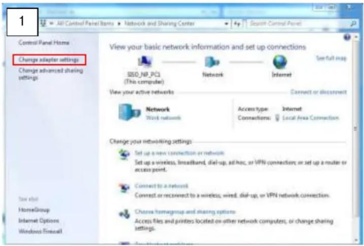
In the following example, based on Windows 7, we will configure the IP address to
192.168.0.99 and set Subnet Mask to 255.255.255.0 by using the steps below:
text_image
1 All Control Panel Items > Network and Sharing Center > 4p Search Control Panel Control Panel Home Change adapter settings Change advanced sharing settings View your basic network information and set up connections SSO_NP_PCI (This computer) Network Internet See full map View your active networks Connect or disconnection Network Work network Access type: Internet Connections: Local Area Connection Change your networking settings Set up a new connection or network Set up a wireless, broadband, dial-up, ad hoc, or VPN connections; or set up a router or access point. Connect to a network Connect or reconnect to a wireless, wired, dial-up, or VPN network connection. Choose homegroup and sharing options Access files and printers located on other network computers; or change sharing settings.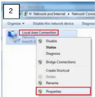
text_image
2 Organize Enable this network device Diagnosis Local Area Connection Network Inter(R) E Disable Status Diagnose Bridge Connections Create Shortcut Delete Rename Properties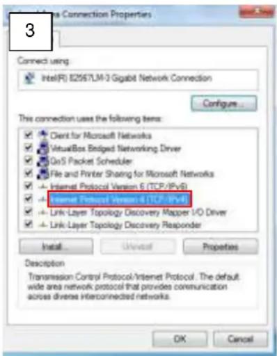
text_image
3 Connect using: Intel(R) E2957LM-3 Gigabit Network Connection Configure... This connection uses the following items: ✓ Client for Microsoft Networks ✓ VirtualBox Bridged Networking Driver ✓ GoS Packet Scheduler ✓ File and Printer Sharing for Microsoft Networks ✓ Internet Protocol Version 6 (TCP/IPvB) ✓ Link Layer Topology Discovery Mapper I/O Driver ✓ Link Layer Topology Discovery Reponder Install Unreal Properties Description Transmission Control Protocol/Internet Protocol. The default wide area network protocol that provides communication across diverse interconnected networks. OK Cancel
text_image
4 You can get IP settings assigned automatically if your network supports this capability. Otherwise, you need to ask your network administrator for the appropriate IP settings. Obtain an IP address automatically Use the following IP address: IP address: 192 . 168 . 0 . 99 Subnet mask: 255 . 255 . 255 . 0 Default gateway: Obtain DNS server address automatically Use the following DNS server addresses: Preferred DNS server: Alternate DNS server: Validate settings upon exit Advanced... OK CancelManually adjust the IP addresses of multiple cameras
If there are more than one camera to be used in the same local area network and there is no DHCP server to assign unique IP addresses to each of them, all of the cameras would then have the initial IP address of 192.168.0.100, which is not a proper situation for network devices – all the IP addresses have to be different from each other. The easiest way to assign cameras the IP addresses is by using IP Utility:
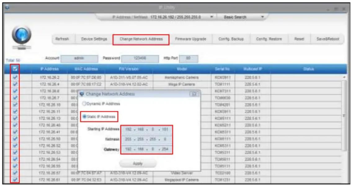
text_image
P Address / NetBank 172.16.25.182 / 255.255.256.0 Refresh Device Settings Change Network Address Firmware Upgrade Config. Backup Config. Restore Reset Save&Reboot Total 56 Account admin Password 123456 Http Port 80 IP Address MAC Address FW Version Model Serial No Multicast IP Status 172.16.26.2 00:0F:7C:87:DE:85 A1D-311-V5.07.05-AC Hemispheric Camera KCM3911 230.5.6.1 172.16.26.4 00:0F:7C:88:17:C2 A1D-310-V4.12.03-AC Mega IP Camera TOM1111 230.5.6.1 172.16.26.6 00:0F:7C:88:17:C2 Change Network Address Dynamic IP Address Static IP Address Starting IP Address 192 . 168 . 8 . 101 Netmask 255 . 255 . 255 . 8 Gateway 192 . 168 . 8 . 254 Apply TOM5B11 230.5.6.1 TOM5B11 230.5.6.1 TOM5B11 230.5.6.1 TOM5B11 230.5.6.1 TOM5B11 230.5.6.1 TOM5B11 230.5.6.1 TOM5B11 230.5.8.1 TOM5B11 230.5.6.1 TOM5B11 230.5.6.1 TOM5B100 230.5.6.1 TOM5B100 230.5.6.1 TOM5B100 230.5.6.1With the procedure shown above, all the cameras will have unique IP addresses, starting from 192.168.0.101. In case there are 20 cameras selected, the last one of the cameras would have the IP 192.168.0.120.
Later, by pressing the "Refresh" button of the IP Utility, you will be able to see the list of cameras with their new IP addresses.
text_image
IP_Utility RefreshPlease note that it is also possible to change the IP addresses manually by using the Web browser. In such case, please plug in only one camera at a time, and change its IP address by using the Web browser before plugging in the next one. This way, the Web browser will not be confused about two devices having the same IP address at the same time.
Access the Camera
Now that the camera and the PC are both having their unique IP addresses and are under the same network segment, it is possible to use the Web browser of the PC to access the camera.
You can use any of the browsers to access the camera, however, the full functionality is provided only for Microsoft Internet Explorer.
The browser functionality comparison:
| Functionality | Internet Explorer | Other browsers |
| Live Video | Yes | Yes* |
| Live Video Area Resizable | Yes | No |
| PTZ Control | Yes | Yes |
| Capture the snapshot | Yes | Yes |
| Video overlay based configuration (Motion Detection regions, Privacy Mask regions) | Yes | No |
| All the other configurations | Yes | Yes |
* When using non-Internet Explorer browsers, free third-party software plug-ins must be installed to the PC first to be able to get the live video feed from the camera:
| Browser | Required Plug-In |
| Safari | QuickTime (http://www.apple.com/quicktime/download/) |
| Other non-Internet Explorer browsers | Basic VLC Media Player (http://www.videolan.org) |
Disclaimer Notice: The camera manufacturer does not guarantee the compatibility of its cameras with VLC player or QuickTime – since these are third party softwares. The third party has the right to modify their utility any time which might affect the compatibility. In such cases, please use Internet Explorer browser instead.
When using Internet Explorer browser, the ActiveX control for video stream management will be downloaded from the camera directly – the user just has to accept the use of such control when prompted so. No other third party utilities are required to be installed in such case.
The examples in this manual are based on Internet Explorer browser in order to cover all functions of the camera.
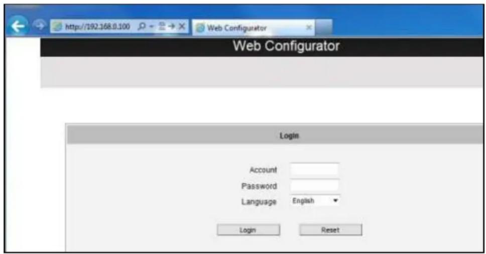
Assuming that the camera's IP address is 192.168.0.100, you can access it by opening the Web browser and typing the following address into Web browser's address bar:
http://192.168.0.100
Upon successful connection to the camera, the user interface called Web Configurator would appear together with the login page. The HTTP port number was not added behind the IP address since the default HTTP port of the camera is 80, which can be omitted from the address for convenience.
text_image
http://192.168.0.100 Web Configurator Web Configurator Login Account Password Language English Login ResetBefore logging in, you need to know the factory default Account and Password of the camera.
Account: Admin
Password: 123456
For further operations, please refer to the Firmware User Manual.

ACTi
Connecting Vision
Copyright © 2015, ACTi Corporation All Rights Reserved
7F, No. 1, Alley 20, Lane 407, Sec. 2, Ti-Ding Blvd., Neihu District, Taipei, Taiwan 114, R.O.C.
TEL: +886-2-2656-2588 FAX: +886-2-2656-2599
Email: sales@acti.com