TCM-7411 - Security Camera ACTi - Free user manual and instructions
Find the device manual for free TCM-7411 ACTi in PDF.


User questions about TCM-7411 ACTi
0 question about this device. Answer the ones you know or ask your own.
Ask a new question about this device
Download the instructions for your Security Camera in PDF format for free! Find your manual TCM-7411 - ACTi and take your electronic device back in hand. On this page are published all the documents necessary for the use of your device. TCM-7411 by ACTi.
USER MANUAL TCM-7411 ACTi
H.264 Megapixel IP Outdoor Rugged Dome Camera Hardware User's Manual
(DC 12V / PoE)
Ver. 2010/1/5
Table of Contents
0. Precautions 3
1. Introduction 4
Package Contents......4
Features and Benefits .... 5
Safety Instructions 7
Physical description....9
2. Installation Procedure 13
Connect the IP Outdoor Rugged Dome 13
1) Remove the cover.... 13
2) Insert the cable....14
3) Connect cables to connectors .... 14
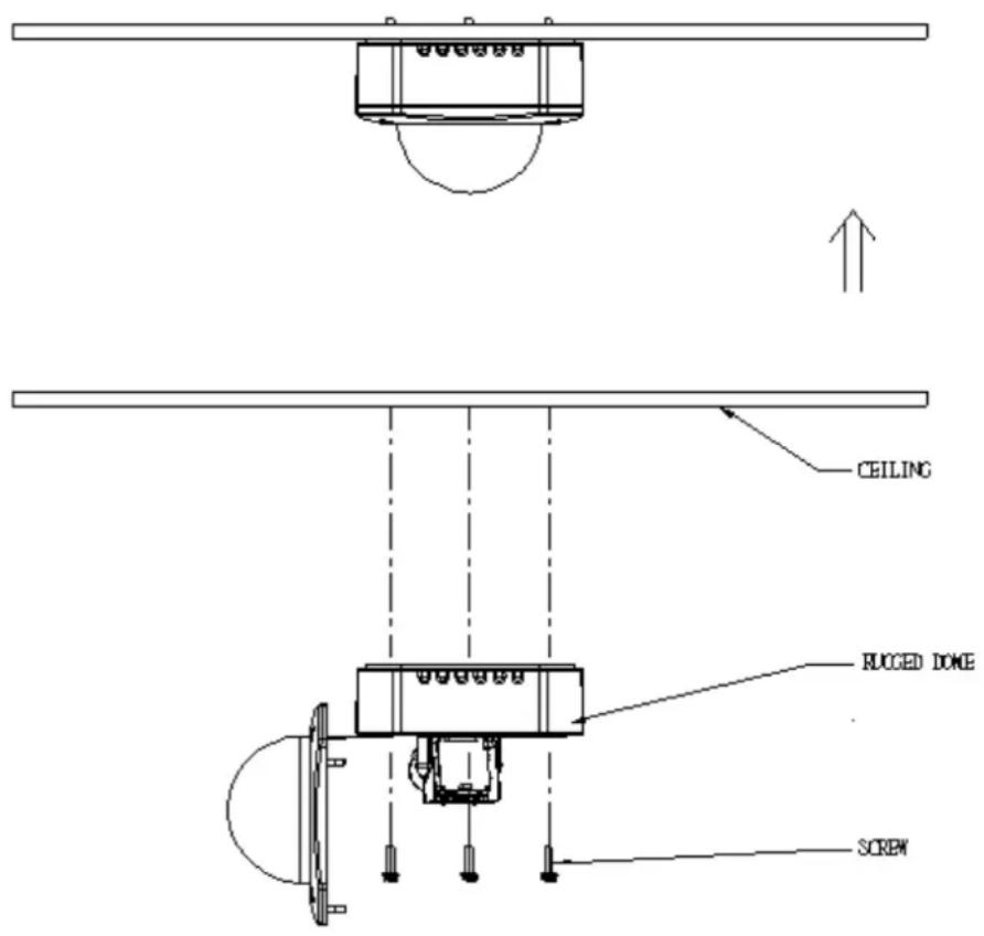
Mount the IP Outdoor Fixed Dome (Surface).... 15
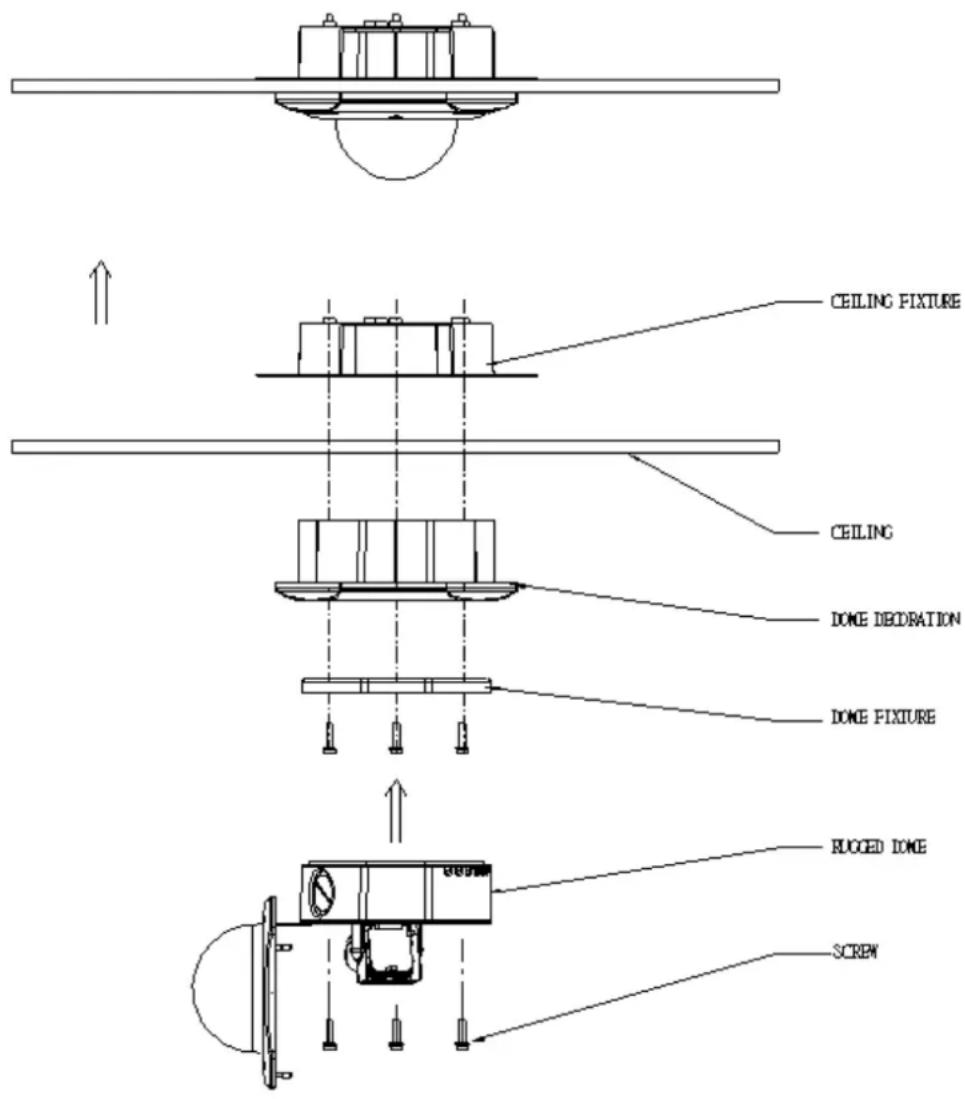
Mount the IP Outdoor Fixed Dome (Flush).... 16
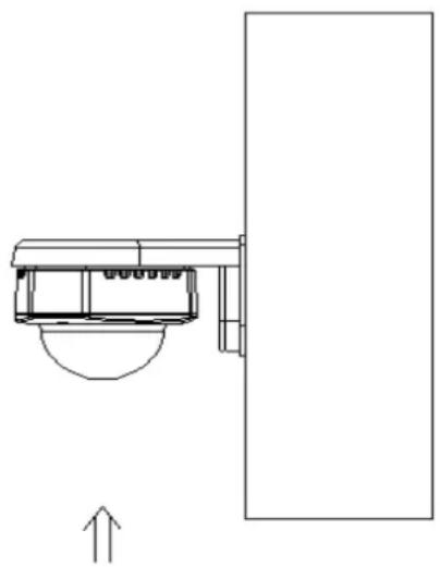
Mount the IP Indoor Fixed Dome (Wall) 17
Adjust the camera....18
Adjust zoom and focus.... 18
Adjust camera functions....18
Product Specification 19
3. Accessing Camera 20
If you have DHCP server / router in your network: 20
If you do NOT have DHCP server / router in your network: ..... 20
0. Precautions
Read these instructions
You should read all the safety and operating instructions before using this product.
Heed all warnings
You must adhere to all the warnings on the product and in the instruction manual. Failure to follow the safety instruction given may directly endanger people, cause damage to the system or to other equipment.
Servicing
Do not attempt to service this video device yourself as opening or removing covers may expose you to dangerous voltage or other hazards. Refer all servicing to qualified service personnel.
Trademarks
All names used in this manual are probably registered trademarks of respective companies.
Liability
Every reasonable care has been taken during the writing of this manual. Please inform your local office if you find any inaccuracies or omissions. We cannot be held responsible for any typographical or technical errors and reserve the right to make changes to the product and manuals without prior notice.
FCC/CE Regulation
NOTE: This equipment has been tested and found to comply with the limits for a Class A digital device, pursuant to Part 15 of the FCC Rules. These limits are designed to provide reasonable protection against harmful interference when the equipment is operated in a commercial environment. This equipment generates, uses, and can radiate radio frequency energy and, if not installed and used in accordance with the instruction manual, may cause harmful interference to radio communications. Operation of this equipment in a residential area is likely to cause harmful interference in which case the users will be required to correct the interference at their own expense.
1. Introduction
Package Contents
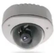
TCM-7411
Power Adaptor (Optional)
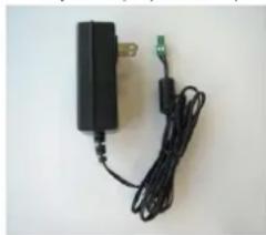
natural_image
Black electronic device with attached cable and connector (no visible text or symbols)Product CD
text_image
ACTI www.acti.comTerminal Blocks for Power, DI/O & Audio
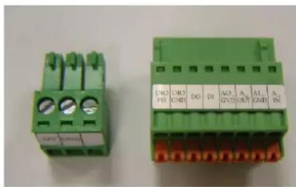
text_image
DRO PV DRO GND DO DI AO GND A OUT AI GND A INWarranty Card
text_image
UNITED HARDWARE STAFFS Copyright: 100% Copyright: 100% Copyright: 100% Copyright: 100% Copyright: 100% Copyright: 100% Copyright: 100% Copyright: 100% Copyright: 100% Copyright: 100% Copyright: 100% Copyright: 100% Copyright: 100% Copyright: 50% Copyright: 50% Copyright: 50% Copyright: 50% Copyright: 50% Copyright: 50% Copyright: 50% Copyright: 50% Copyright: 50% Copyright: 50% Copyright: 50% Copyright: 50% Copyright: 50% Copyright: 50% Copyright: 50% Copyright: 50% Copyright: 50% Copyright: 50% Copyright: 50% Copyright: 50% Copyright: 50% Copyright: 50% Copyright: 50% Copyright: 50% Copyright: 50% Copyright: 50% Copyright: 50% Copyright: 50% Copyright: 50% Copyright: 50% Copyright: 50% Copyright: 100% Copyright: 100% Copyright: 100% Copyright: 100% Copyright: 100% Copyright: 100% Copyright: 100% Copyright: 100% Copyright: 100% Copyright: 100% Copyright: 100% Copyright: 100% Copyright: 25% Copyright: 25% Copyright: 25% Copyright: 25% Copyright: 25% Copyright: 25% Copyright: 25% Copyright: 25% Copyright: 25% Copyright: 25% Copyright: 25% Copyright: 25% Copyright: 25% Copyright: 25% Copyright: 25% Copyright: 25% Copyright: 25% Copyright: 30% Copyright: 30% Copyright: 30% Copyright: 30% Copyright: 30% Copyright: 30% Copyright: 30% Copyright: 30% Copyright: 30% Copyright: 30% Copyright: 30% Copyright: 30% Copyright: 30% Copyright: 30% Copyright: 30% Copyright: 30% Copyright: 30% Copyright: -1 Copyright: -1 Copyright: -1 Copyright: -1 Copyright: -1 Copyright: -1 Copyright: -1 Copyright: -1 Copyright: -1 Copyright: -1 Copyright: -1 Copyright: -1 Copyright: -1 Copyright: -1 Copyright: -1 Copyright: -1 Copyright: -1 Copyright: -1 Copyright: -1 Copyright: -1 Copyright: -1Accessories
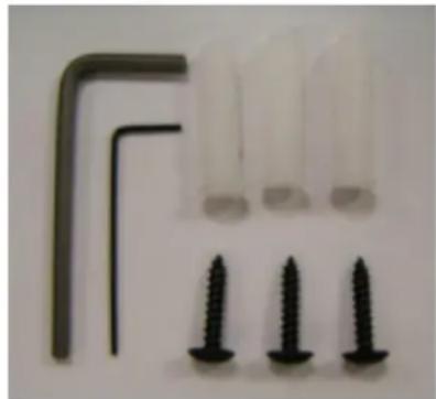
natural_image
Close-up of three white plastic test tubes and three black screws arranged in a row (no text or symbols visible)Drill Template
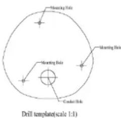
text_image
Mounting Hole Mounting Hole Cractor Hole Drill template(scale 1:1)Features and Benefits
This is a cutting-edge digital video surveillance camera. It can compress and transmit real time images with outstanding image quality (18 FPS @ SXGA, 1280x1024) through a standard TCP/IP network. This camera is your best choice to build an intelligent IP surveillance system.
H.264/MPEG-4/MJPEG Triple Codec Dual Streaming
This device supports 3 compression formats, H.264, MPEG-4 and MJPEG. It brings superior image quality at 18 frames per second up to a resolution of SXGA (1280 x 1024) pixels, and offers up to 26 frames per second in HD720 (1280x720). In D1 (720 x 480) / VGA (640 x 480) / QVGA / QQVGA the device reaches 30 frames per second.
Wide Dynamic Range
This IP camera includes a special process that enhances the view in the brightest and darkest areas. This provides for more evenly illuminated image and brings out greater details to the eye.
Rugged Vandal-Proof Construction withstands all kinds of abuse.
Special engineer polymer clear dome shell protects against brute force impact. It is extremely durable against any tampering intruder. IP66 construction isolates electronics against the elements. Rain, sleet or snow, nothing goes through. Temperature control ensures cold-start capability for use in the worst of weathers.
Built-in Hardware Motion Detection
No more external motion sensors are required. You may assign up to 3 video motion detection areas. By tuning the object size and sensitivity, it will reliably detect objects passing through in view. Hardware motion detection also offers better sensitivity and faster response time than software motion detection.
Powerful Bundled Surveillance Software
To extend the capabilities of the IP Camera, a powerful surveillance program is included in the package for free. Users can easily use an existing PC as a digital video recorder. Scheduled recording and manual recording keep every important video recorded in the local hard disk. Reliable and accurate motion detection with instant warning enables immediate response in every condition. Quick and simple search and playback function lets you easily find the images and video you want.
Software Development Kit Support
This IP Camera can be integrated or controlled by applications from third party software developers. Software developers can save considerable efforts by using our Streaming Library or ActiveX control. Please contact us for details on integration support.
Digital Time Code Embedded
The “Digital Time Code Embedded” function records video time in the video stream. Therefore, each image frame is marked with its original recording time. It is very useful when users want to find the video at an exact time or between a certain time intervals.
Safety Instructions
Don't use the power supply with other voltages
This device is likely to be damaged or damage other equipments / personnel, if you use a power supply with different voltage than the one included with this device. All warranty of this product will be voided in the situations above.
Cleaning
Disconnect this video product from the power supply before cleaning.
Attachments
Do not use attachments not recommended by the video product manufacturer as they may cause hazards.
Water and Moisture
Do not use this video product near water, for example, near a bathtub, washbowl, kitchen sink, or laundry tub, in a wet basement, or near a swimming pool and the like.
Don't use accessories not recommended by the manufacturer
Only install this device and the power supply in a dry place protected from weather
Servicing
Do not attempt to service this video product yourself as opening or removing covers may expose you to dangerous voltage or other hazards. Refer all servicing to qualified service personnel.
Damage Requiring service
Disconnect this video product from the power supply immediately and refer servicing to qualified service personnel under the following conditions.
1) When the power-supply cord or plug is damaged
2) If liquid has been spilled, or objects have fallen into the video product.
3) If the video product has been directly exposed to rain or water.
4) If the video product does not operate normally by following the operating Instructions in this manual. Adjust only those controls that are covered by the instruction manual, as an improper adjustment of other controls may result in damage, and will often require extensive work by a qualified technician to restore the video product to its normal operation.
Safety Check
Upon completion of any service or repairs to this video product, ask the service technician to perform safety checks to determine if the video product is in proper operating condition.
Physical description
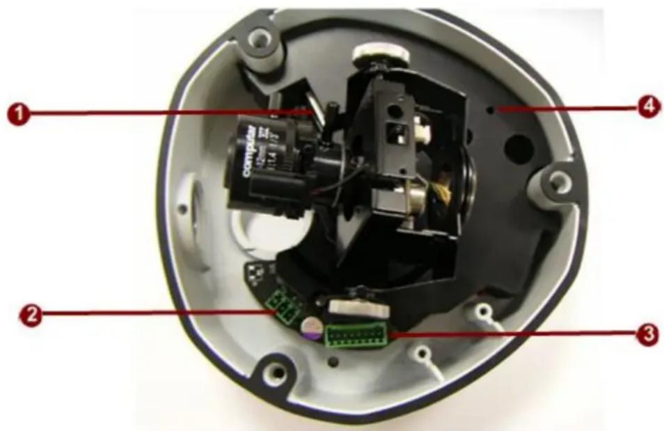
text_image
Labeled diagram of an electronic device showing internal components and parts with numbered annotations1) Ethernet Port
The IP device connects to the Ethernet via a standard RJ45 connector. Supporting NWAY, this IP device can auto detect the speed of local network segment (10Base-T/100Base-TX Ethernet).
2) Power Input
Connect the power adaptor here if your power input is DC12V.
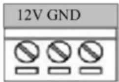
text_image
12V GND| PIN | NAME | DESCRIPTION |
| 1 | 12V | DC Power Input |
| 2 | GND | Ground Pin |
3) Digital Input / Output & Audio Terminal Connector
This IP Camera supports DI/O & Audio input / output via terminal block.
Used in applications like motion detection, event triggering, time lapse recording, alarm notifications, etc., the I/O terminal connector provides an interface to respective devices. The Terminal Block wiring diagram is as follows:
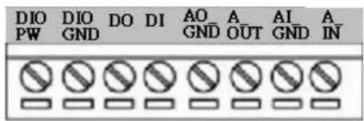
text_image
DIO PW DIO GND DO DI AO GND A OUT AI GND A IN| PIN | NAME | DESCRIPTION |
| 1 | DIO PW | DC12VIN |
| 2 | DIO GND | DGND |
| 3 | DO | DO1_TO_OUTSIDE |
| 4 | DI | DI1_FROM_OUTSIDE |
| 5 | AO_GND | DGND |
| 6 | A_OUT | Audio_OUT_LR |
| 7 | AI_GND | DGND |
| 8 | A_IN | Audio_IN |
This camera provides:
-1 transistor output - For connecting external devices such as relays and LEDs. Connected devices can be activated by Output buttons on the Live View page or through video management software.
-1 Digital Input - An alarm input for connecting devices that can toggle between an open and closed circuit, for example: PIRs, door/window contacts, glass break detectors, etc. The device will detect the change in digital input and transmit the signal to video surveillance servers.
Terminal Pin Define is described as below:
| Pin Name | Description | Spec |
| DIO PW | Electrically connected in parallel with the connector for the power supply, this pin provides an auxiliary connector for mains power to the unit. This pin can also be used to power auxiliary equipment, with a maximum current of 100mA. | Voltage: 12V DC, Max: 1.2W |
| DIO GND | Ground | |
| DO (Transistor Output) | Uses an open-collector NPN transistor with the emitter connected to the GND pin. If used with an external relay, a diode must be connected in parallel with the load, for protection against transient voltages. | Max load = <100mA Max voltage = 24V DC (to the transistor) |
| DI (Digital Input) | Connect to GND to activate, or leave floating (or unconnected) to deactivate. | Must not be exposed to voltages greater than 30V DC. |
4) Reset Button
Step 1: Switch off IP device by disconnecting the power cable
Step 2: Press and continue to hold the Reset Button (with a sharp tipped object, like a pen.)
Step 3: Reconnect the power cable while continuing to hold the reset button. The red Power LED light will flash on for 3 second first, turn off for about 15 seconds, flash on for another second and turn off again. By this time the reset to default operation is already completed. This will take around 20 seconds from power up. You may then release the reset button. This length of time fluctuates slightly with the environment. The Power LED light will come back on and stay on after a few more seconds. The unit will start up with factory default settings automatically.
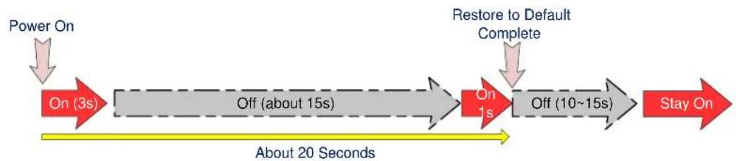
flowchart
graph LR
    A["Power On"] --> B["On (3s)"]
    B --> C["Off (about 15s)"]
    C --> D["On 1s"]
    D --> E["Off (10~15s)"]
    E --> F["Stay On"]
    G["Restore to Default Complete"] --> D
    H["About 20 Seconds"] --> I
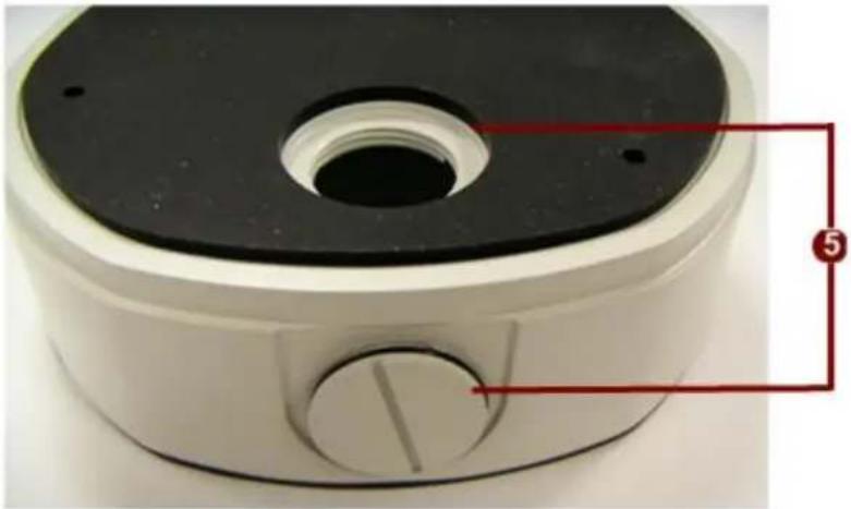
5) Conduit Hole
Conduit Holes are openings where cables pass through. There are two conduit holes on this device, used for different mounting angles.
natural_image
Close-up of a mechanical component with a black top and central hole, labeled with red annotation number 5 (no text or symbols on the object itself)6) LED Descriptions
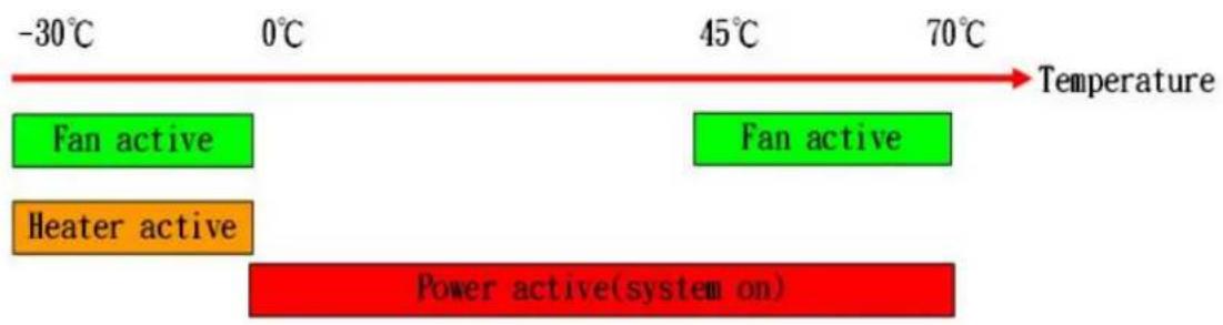
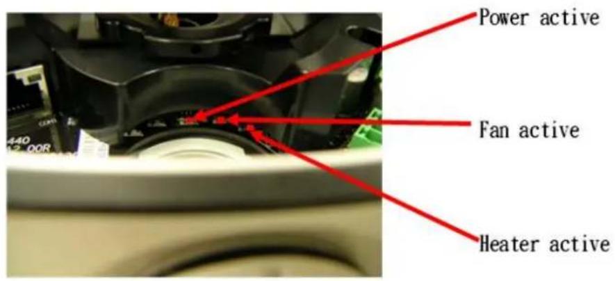
There are three Red LEDs in the system. They indicate the operational status for power, fan and heater. These LEDs will light up in different configurations under different temperature, indicating the temperature control mechanism at work. The detail is shown in the chart below. Please note that this is the "Internal Temperature" as measured by the electronics. The external temperature will be different from the internal temperature in most cases.
Note: PoE powered rugged dome does not have enough power available and cannot support Heater.
flowchart
graph LR
    A["-30°C"] --> B["Fan active"]
    C["0°C"] --> D["Heater active"]
    E["45°C"] --> F["Fan active"]
    G["70°C"] --> H["Power active(system on)"]
    style A fill:#fff,stroke:#000
    style C fill:#fff,stroke:#000
    style E fill:#fff,stroke:#000
    style G fill:#fff,stroke:#000
    style H fill:#fff,stroke:#000
text_image
Power active Fan active Heater active2. Installation Procedure
There are three types of installation methods for this IP outdoor rugged dome camera.
| Surface mount | Flush mount | Wall mount | |
| Pictures |  | 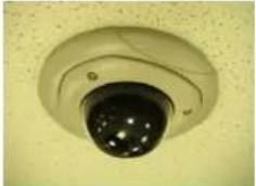 | 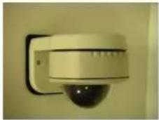 |
| Optional Bracket required | ● | ● |
The mounting procedure can be divided into two parts,
1st: Connect the IP outdoor rugged dome series
2^nd : Mount the IP outdoor rugged dome series
Connect the IP Outdoor Rugged Dome
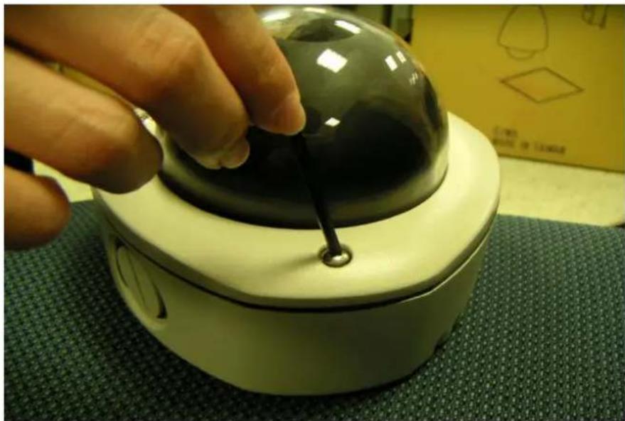
1) Remove the cover
Remove the dome cover with special hex wrench in the accessory kit.
natural_image
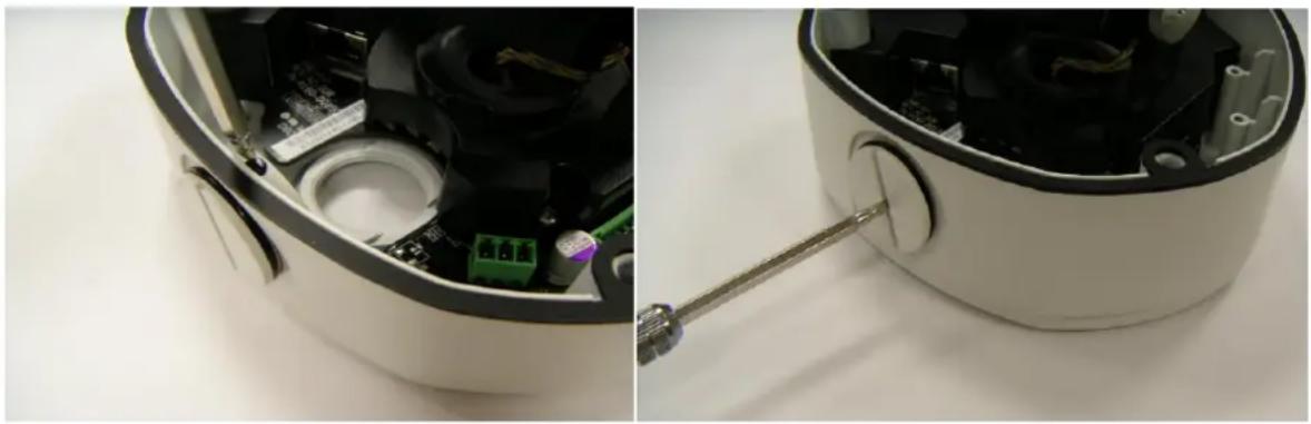
Close-up of a hand adjusting a black dome-shaped object with a string, placed on a green textured surface (no visible text or symbols)2) Insert the cable
There are two conduit holes on this rugged dome. One is at the bottom, while the other is at the side and covered with a plug. Remove the plug if your cable will go through the one at the side of the rugged dome
natural_image
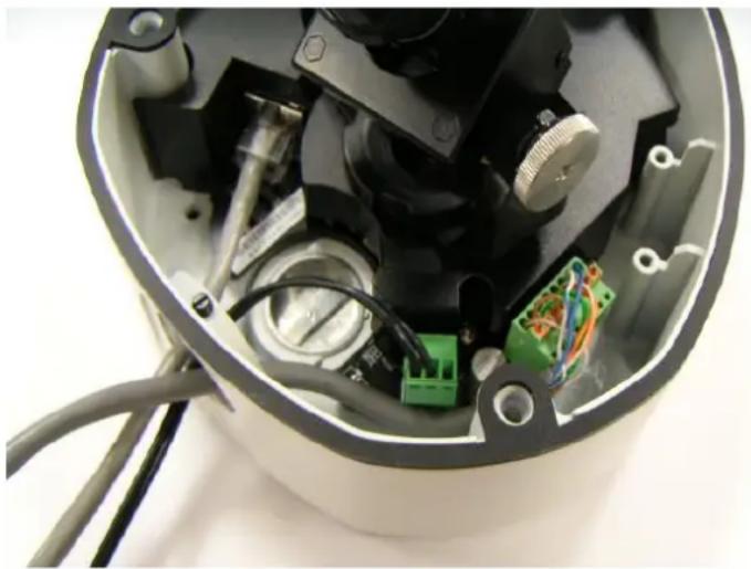
Interior view of a device showing internal components and a tool inserted into a circular housing (no visible text or symbols)3) Connect cables to connectors
Please follow the instructions in the Physical Description section for how to connect to each connector.
natural_image
Interior view of an open industrial device showing internal components like a green connector and wiring (no visible text or symbols)Mount the IP Outdoor Fixed Dome (Surface)
text_image
CEILING ROCCED DOME SCREWMount the IP Outdoor Fixed Dome (Flush)
text_image
CEILING FIXTURE CEILING DONE DEEDRATION DONE FIXTURE RUGGED DIME SCREWMount the IP Indoor Fixed Dome (Wall)
natural_image
Simple line drawing of a wall-mounted device mounted on a vertical panel, with an upward arrow indicating motion (no text or symbols)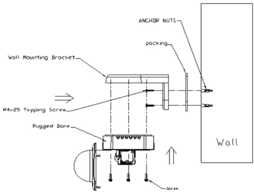
text_image
ANCHOR NUTS pocking WALL Mounting Bracket M4×25 Topping Screw Rugged Done Wall Screw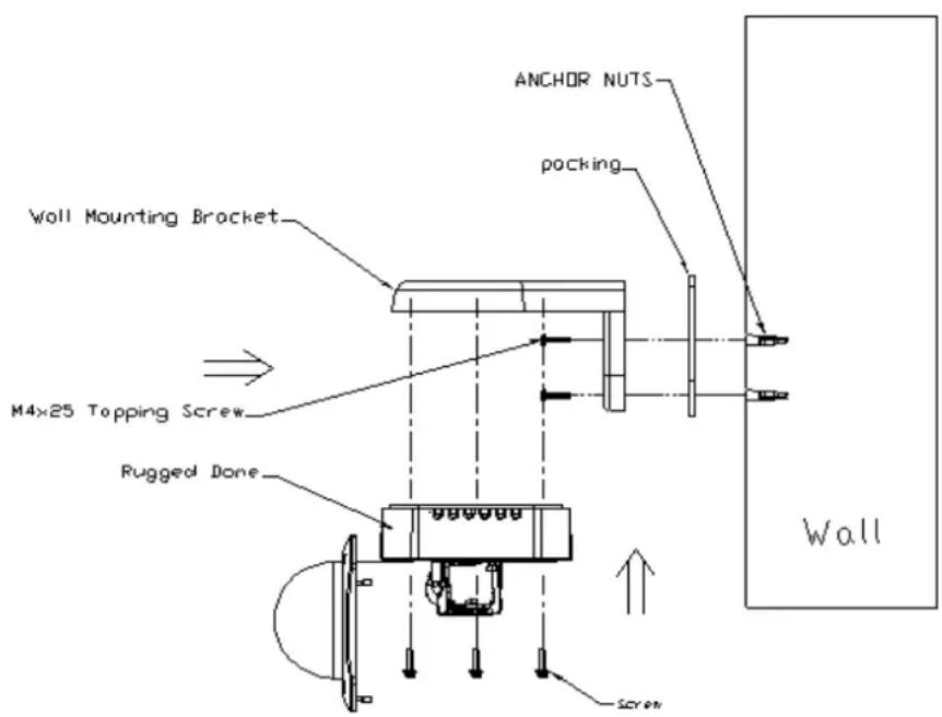
text_image
ANCHOR NUTS pocking WALL Mounting Bracket M4×25 Topping Screw Rugged Done Screw WallAdjust the camera
Adjust zoom and focus
Please adjust the camera direction first. Then move the focus and the zoom lever adjust the zoom and the focus. Fix the zoom and focus after adjusting.
Adjust camera functions
The illustration below shows where to adjust each axis.
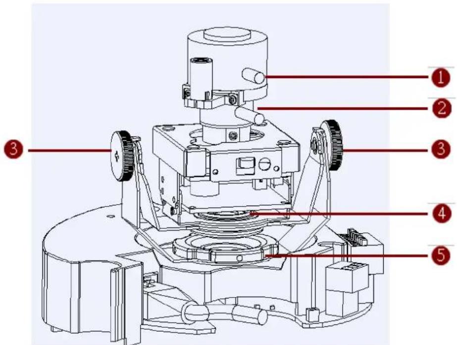
text_image
Technical diagram of a mechanical device with numbered parts labeled 1 to 5Picture 1
- Focus lever
- Zoom lever
- Tilt adjustment screw
- Image adjustment axis
- Pan adjustment screw
Product Specification
| TCM-7411 | ||
| Image | Device Micron Progressive Scan CMOS | |
| Size 1/3 inch | ||
| Effective Pixels 1280(H) x 1024 (V) | ||
| Min. scene Illumination | Color Color mode automatically switched to B/W mode under 4 Lux | |
| B/W 0.05 Lux at F1.0 (2400 °K, 30 IRE) | ||
| CDS Sensor Yes | ||
| IR Sensitivity from 700nm to 1100nm | ||
| Lens | Lens f3.3mm~ 12mm/ F1.6 | |
| Viewing Angle 89.8° ~ 23.9° (Horizontal) | ||
| Camera Angle Adjustment | X (Panning) 0° ~360° | |
| Y (Tilting) | 0° ~180° | |
| Z (Rotating) | 0° ~360° | |
| Synchronization | Sync. System | Internal |
| Day/Night functions | Mechanical IR Cut Filter | Yes |
| Functions | Motion Detection | Yes (3 Windows) |
| Electronic shutter | 1/5 ~ 1/15,000 sec | |
| Fixed Shutter (Manual) | 1/30 ~ 1/1,000 sec. (60Hz)1/25 ~ 1/1,000 sec. (50Hz) | |
| Flickerless | 1/120 sec. (60Hz)1/100 sec. (50Hz) | |
| BLC | Yes | |
| AGC | Automatic (User defined) | |
| White Balance | Auto, Indoor1, Indoor2, Outdoor1, Outdoor2, Hold Current, Manual | |
| Wide Dynamic Range | Yes | |
| S/N Ratio | S/N Ratio | Better than 44 dB |
| Video Compression | Compression | H.264/ MPEG-4 SP/ MJPEG simultaneous dual streams selectable |
| Picture Resolution | SXGA (1280x1024)HD 720 (1280x720)VGA (640x480)QVGA (320x240)QQVGA (160x112) | |
| Bit Rate | 28K ~ 6M bps | |
| Image Frame Rate | 18 fps at SXGA; 26 fps at HD720; 30 fps at VGA; 30 fps at QVGA; 30 fps at QQVGA | |
| Audio Input | Compression | 8kHz, Mono, PCM |
| Audio Line Input | Unbalanced, 1.4Vp-p, 1Vrms, terminal block | |
| Audio Output | Compression | 8kHz, Mono, PCM |
| Audio Line Output | Unbalanced, 1.4Vp-p, 1Vrms, terminal block | |
| Alarm | Digital Input | 1, TTL, Terminal Block |
| Digital Output | 1, TTL, Terminal Block | |
| External I/O | Reset Button | Factory Default |
| LED | System status/ Fan / Heater | |
| Casing | IP66 Rated | Weatherproof casing with IP66 standard |
| Vandal Proof | Vandal proof supports, durability up to 659.23 KgF | |
| Mount Types | Surface / Flush / Wall | |
| Network | Ethernet | Ethernet(10/100 Base-T), RJ-45 connector |
| Protocol | TCP, UDP, HTTP, HTTPS, DHCP, PPPoE, RTP, RTSP, DNS, DDNS, NTP, ICMP, ARP, IGMP, SMTP, FTP, UPnP, IPv6 | |
| Software | Web Browser | Microsoft Internet Explorer 6.0 or above |
| SDK | ACTi SDK-10000 | |
| Security | Password Protection: Configured by the Administrator | |
| Operating | Heater/ Fan | Yes (Built in) |
| Temperature | -30 °C ~ 50 °C (-22 °F ~ 122 °F) for DC 12V; -5 °C ~ 50 °C (7 °F ~ 122 °F) for PoE | |
| Power | Power Requirement | PoE (IEEE 802.3af) with Class 3 |
| Power Consumption | 4.8 W (DC 12V) w/o Heater & Fan13.68 W (DC 12V) w/ Heater ON & Fan ON6.24 W (PoE) w/o Heater & Fan7.68 W (PoE) w/ Fan ON* | |
| Physical | Dimensions (∅ xH) | 151.69 mm x 114.9 mm (6.0" x 4.5") |
| Weight | 1040 g (2.29 lb) | |
| Approvals | Certificate | CE, FCC, IP66 |
* PoE cannot support Heater.
3. Accessing Camera
If you have DHCP server / router in your network:
Many network server / routers are able to automatically provide IP addresses through DHCP. If you are using such a network, just plug in your computer and IP Camera into the network and your IP device will acquire network address by itself. Find and access the device with our IP Utility program. You may download it at:
http://www.acti.com/product/detail/Software/ACTi_Utility_Suite
If you do NOT have DHCP server / router in your network:
- Configure your PC to use the same subnet by changing your PC's IP address to the subnet with prefix 192.168.0.XXX. The last number should be anything from 1 to 254 except 100 and other occupied IP addresses. Subnet mask should be 255.555.255.0.
- The default IP used by this device is 192.168.0.100. Please make sure your PC is NOT using this address and that no two equipments use the same IP address in the network.
- Change your IP address by going to Control Panel ->Manage Network Connections -> Right click on the connection to change -> Option -> TCP/IP IPv4 Properties.
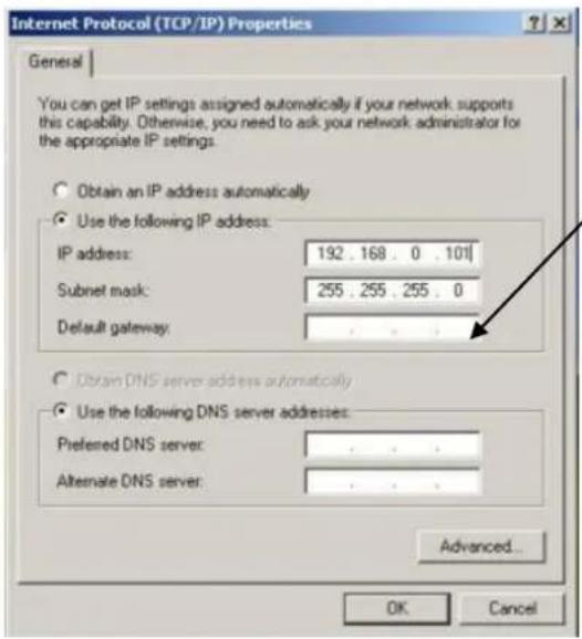
text_image
Internet Protocol (TCP/IP) Properties General You can get IP settings assigned automatically if your network supports this capability. Otherwise, you need to ask your network administrator for the appropriate IP settings. Obtain an IP address automatically Use the following IP address: IP address: 192 . 168 . 0 . 101 Subnet mask: 255 . 255 . 255 . 0 Default gateway: Obtain DNS server address automatically Use the following DNS server addresses: Preferred DNS server: Alternate DNS server: Advanced... OK CancelPlease set the settings as below.
●
- IP address: 192.168.0.xxx
- Subnet mask: 255.255.255.0
(NOTE: xxx should be a number from 1 to 254 except 100, which is used by the IP device. Please also make sure that no two equipments use the same IP address in the same network..)
- Open Internet Explorer (Version 6.0 or above), and type in the Default IP:
192.168.0.100
- When you see the login window, please input default user and password:
Default User: Admin
Password: 123456
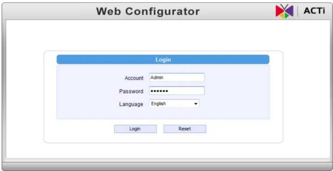
text_image
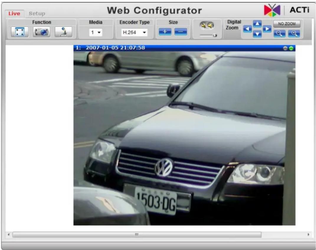
Web Configurator Login Account Admin Password ••••••• Language English Login Reset- After logging in, you will see the video from camera. To go to the main menu, click the "Setup" button on the top left.
text_image
Web Configurator Live Setup ACTi Function Media Encoder Type Size Digital Zoom NO ZOOM 1: 2007-01-05 21:07:58 1503-DGIf you are using a single camera, this is enough to access the device.
If you are using multiple devices, you need to change the current device to another unused IP address, so that when the next device is connected to the network, no two devices use the same IP. Please perform the following steps.
- Go to Network -> Connection Type
- Change the IP mode to Static.
- Change the IP to 192.168.0.101 or any other unused IPs. Do NOT use the PC's IP address or 192.168.0.100.). If this is not the first device you add to the network, please also avoid other devices' IPs.
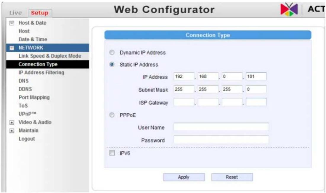
text_image
Web Configurator Live Setup Host & Date Host Date & Time NETWORK Link Speed & Duplex Mode Connection Type IP Address Filtering DNS DDNS Port Mapping ToS UPnP™ Video & Audio Maintain Logout Connection Type Dynamic IP Address Static IP Address IP Address 192 168 0 101 Subnet Mask 255 255 255 0 ISP Gateway PPPoE User Name Password IPV6 Apply Reset-
Click "Apply"
-
Please go to Maintain -> Save & Reboot, and click "Apply". Internet Explorer will close after a few seconds. This is normal.
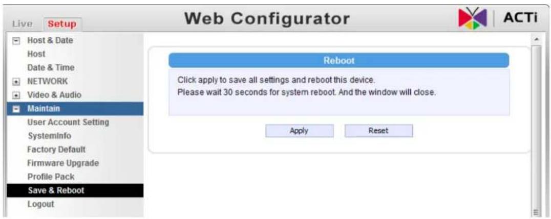
text_image
Web Configurator Live Setup Host & Date Host Date & Time NETWORK Video & Audio Maintain User Account Setting SystemInfo Factory Default Firmware Upgrade Profile Pack Save & Reboot Logout Reboot Click apply to save all settings and reboot this device. Please wait 30 seconds for system reboot. And the window will close. Apply Reset- Wait for 30 seconds, and open IE again to connect to the new IP. (In this example, 192.168.0.101). For the second device or more you add into the network, please type the correct IP.
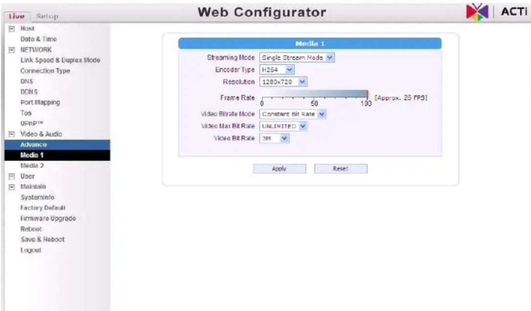
- Adjust the default Video setting by going to Video & Audio -> Media 1