
C1121X-8PLTEPWE - Router CISCO - Free user manual and instructions
Find the device manual for free C1121X-8PLTEPWE CISCO in PDF.


User questions about C1121X-8PLTEPWE CISCO
0 question about this device. Answer the ones you know or ask your own.
Ask a new question about this device
Download the instructions for your Router in PDF format for free! Find your manual C1121X-8PLTEPWE - CISCO and take your electronic device back in hand. On this page are published all the documents necessary for the use of your device. C1121X-8PLTEPWE by CISCO.
USER MANUAL C1121X-8PLTEPWE CISCO
natural_image
Rooftop solar panel array in front of a modern city skyline at sunset, with no visible text or symbols.HardwareInstallationGuidefortheCisco1000SeriesIntegrated ServicesRouter
AmericasHeadquarters
CiscoSystems, Inc.
170WestTasmanDrive
SanJose, CA95134-1706
USA
http://www.cisco.com
Tel:408526-4000
800553-NETS(6387)
Fax:408527-0883
THE SPECIFICATIONS AND INFORMATION REGARDING THE PRODUCTS IN THIS MANUAL ARE SUBJECT TO CHANGE WITHOUT NOTICE. ALL STATEMENTS, INFORMATION, AND RECOMMENDATIONS IN THIS MANUAL ARE BELIEVED TO BE ACCURATE BUT ARE PRESENTED WITHOUT WARRANTY OF ANY KIND, EXPRESS OR IMPLIED. USERS MUST TAKE FULL RESPONSIBILITY FOR THEIR APPLICATION OF ANY PRODUCTS.
THE SOFTWARE LICENSE AND LIMITED WARRANTY FOR THE ACCOMPANYING PRODUCT ARE SET FORTH IN THE INFORMATION PACKET THAT SHIPPED WITH THE PRODUCT AND ARE INCORPORATED HEREIN BY THIS REFERENCE. IF YOU ARE UNABLE TO LOCATE THE SOFTWARE LICENSE OR LIMITED WARRANTY, CONTACT YOUR CISCO REPRESENTATIVE FOR A COPY.
The following information is for FCC compliance of Class A devices: This equipment has been tested and found to comply with the limits for a Class A digital device, pursuant to part 15 of the FCC rules. These limits are designed to provide reasonable protection against harmful interference when the equipment is operated in a commercial environment. This equipment generates, uses, and can radiate radio-frequency energy and, if not installed and used in accordance with the instruction manual, may cause harmful interference to radio communications. Operation of this equipment in a residential area is likely to cause harmful interference, in which case users will be required to correct the interference at their own expense.
The following information is for FCC compliance of Class B devices: This equipment has been tested and found to comply with the limits for a Class B digital device, pursuant to part 15 of the FCC rules. These limits are designed to provide reasonable protection against harmful interference in a residential installation. This equipment generates, uses and can radiate radio frequency energy and, if not installed and used in accordance with the instructions, may cause harmful interference to radio communications. However, there is no guarantee that interference will not occur in a particular installation. If the equipment causes interference to radio or television reception, which can be determined by turning the equipment off and on, users are encouraged to try to correct the interference by using one or more of the following measures:
- Rcorient or relocate the receiving antenna.
- Increase the separation between the equipment and receiver.
- Connect the equipment into an outlet on a circuit different from that to which the receiver is connected.
- Consult the dealer or an experienced radio/TV technician for help.
Modifications to this product not authorized by Cisco could void the FCC approval and negate your authority to operate the product.
The Cisco implementation of TCP header compression is an adaptation of a program developed by the University of California, Berkeley (UCB) as part of UCB's public domain version of the UNIX operating system. All rights reserved. Copyright 1981, Regents of the University of California.
NOTWITHSTANDING ANY OTHER WARRANTY HEREIN, ALL DOCUMENT FILES AND SOFTWARE OF THESE SUPPLIERS ARE PROVIDED "AS IS" WITH ALL FAULTS. CISCO AND THE ABOVE-NAMED SUPPLIERS DISCLAIM ALL WARRANTIES, EXPRESSED OR IMPLIED, INCLUDING, WITHOUT LIMITATION, THOSE OF MERCHANTABILITY, FITNESS FOR A PARTICULAR PURPOSE AND NONINFRINGEMENT OR ARISING FROM A COURSE OF DEALING, USAGE, OR TRADE PRACTICE.
IN NO EVENT SHALL CISCO OR ITS SUPPLIERS BE LIABLE FOR ANY INDIRECT, SPECIAL, CONSEQUENTIAL, OR INCIDENTAL DAMAGES, INCLUDING, WITHOUT LIMITATION, LOST PROFITS OR LOSS OR DAMAGE TO DATA ARISING OUT OF THE USE OR INABILITY TO USE THIS MANUAL, EVEN IF CISCO OR ITS SUPPLIERS HAVE BEEN ADVISED OF THE POSSIBILITY OF SUCH DAMAGES.
Any Internet Protocol (IP) addresses and phone numbers used in this document are not intended to be actual addresses and phone numbers. Any examples, command display output, network topology diagrams, and other figures included in the document are shown for illustrative purposes only. Any use of actual IP addresses or phone numbers in illustrative content is unintentional and coincidental.
All printed copies and duplicate soft copies of this document are considered uncontrolled. See the current online version for the latest version.
Cisco has more than 200 offices worldwide. Addresses and phone numbers are listed on the Cisco website at www.cisco.com/go/offices.
Cisco and the Cisco logo are trademarks or registered trademarks of Cisco and/or its affiliates in the U.S. and other countries. To view a list of Cisco trademarks, go to this URL: https://www.cisco.com/e/cn/us/about/legal/trademarks.html. Third-party trademarks mentioned are the property of their respective owners. The use of the word partner does not imply a partnership relationship between Cisco and any other company. (1721R)
© 2017–2019 Cisco Systems, Inc. All rights reserved.

natural_image
City skyline with modern skyscrapers and solar panels in foreground, no visible text or symbolsCONTENTS
CHAPTER 1
OverviewofCisco1000SeriesIntegratedServicesRouters1
About Cisco 1000 Series Integrated Service Routers 1
Chassis Views 4
LED Indicators 13
Reset Button 20
Power Supply 20
Slots and Interfaces 21
About Slots, Subslots, and Port Numbering 21
Specifications of Cisco 1100 Series Integrated Services Routers 21
Periodic Inspection and Cleaning 21
CHAPTER 2
PrepareforRouterInstallation23
Safety Recommendations 23
Safety With Electricity 24
Prevent Electrostatic Discharge Damage 24
General Site Requirements 24
Site Selection Guidelines 25
Rack Requirements 25
Safety Recommendations 26
Power Guidelines and Requirements 26
Network Cabling Specifications 27
Console Port Considerations 27
EIA/TIA-232 27
USB Serial Console 27
Console Port Considerations 28
Prepare for Router Installation 29
Ethernet Connections 29
Required Tools and Equipment for Installation and Maintenance 29
CHAPTER 3
InstallandConnecttheRouter31
Unpack the Router 31
Set up Router on Desktop, Rack, or Wall 31
Rack Mount 32
Attach the Brackets for C111x 32
Attach the Rack Mounting Brackets for C112x 33
Mount the Router 34
Mount the Router under a Desk or a Shelf 35
Mount Router using DIN Rail Brackets 36
Attach Din-Rail Brackets on C112x 37
Wall Mount the Router 38
Wall Mount Using Key-hole Slots 38
Wall Mount using DIN Rail Brackets 45
Chassis Grounding 48
Connect Power Cable 50
Connect the Router to a Console 52
Connect to the Serial Port with Microsoft Windows 54
Connect to the Console Port with Mac OS X 55
Connect to the Console Port with Linux 55
Connect WAN and LAN Interfaces 56
Ports and Cabling 56
Connection Procedures and Precautions 57
Configure the Router at Startup 57
CHAPTER 4
InstallandUpgradeInternalModulesandFieldReplaceableUnits59
Replace the Chassis Covers for C111X and C1111x 59
Remove the Cover 60
Replace the Cover 61
External Modules 62
Locate External Slots for Modules 62
Install and Remove Small Form Pluggable Modules 63
Install Small Form Pluggable Module 63
Remove Small Factor Pluggable Module 63
Install an LTE Pluggable Module 64
Install an LTE Pluggable Module on a C1101-4P 65
Install a Micro-SIM Card into a USB LTE Dongle 69
Antenna Mounting Instructions 72
Rack Mount of the Antenna 72
Wall Mount of the Antenna 74
Ceiling Mount of the Antenna 76
CHAPTER 5
ROMMONitorOverview79
ROM Monitor Overview 79
CHAPTER 6
SupplierDeclarationofConformity81
Contents

text_image
CHAPTER 1OverviewofCisco1000SeriesIntegrated ServicesRouters
Cisco 1000 Series Integrated Services Routers (ISRs) with Cisco IOS XE Software are high-performance devices that are easy to deploy and manage. The routers combine Internet access, comprehensive security, and wireless services (LTE Advanced 3.0, Wireless WAN and Wireless LAN).
- About Cisco 1000 Series Integrated Service Routers, on page 1
• Periodic Inspection and Cleaning, on page 21
AboutCisco1000SeriesIntegratedServiceRouters
The Cisco 1000 series Integrated Services Routers are the next generation, IOS XE based, multi core, br routers. They are available in both fixed and modular form factors. The Cisco 1000 series is best suited small and midsize businesses, enterprise branches and as customer premises equipment in managed service environments.
Table1:BaseModelsoftheCisco1000SeriesISR
| Base Models | Panel Switch Ports | ConsolePortW/ANR04aFront(Optional) POE | WLAN | (Optional)LTE | (Optional) DSL | |
| 8C111x-8P (1 Combo RJ-45/SFP + 1 RJ-45) | Micro USB | None4PoE/2P | 4E+Serial RJ LTE-Advanced (CAT6) with carrier aggregation | |||
| 8C111X28P1 Combo RJ-45/SFP + 1 RJ-45) | Micro USB | NoneNoneNone4PoE/ | ||||
| Base Models | Panel Switch Ports | ConsolePortWAP PortsFront POE | (Optional) WLAN | (Optional) LTE | (Optional) DSL | |
| 4C111x-4P (1 Combo RJ-45/SFP + 1 RJ-45) | Serial RJ-45, Micro USB | 2 POE/1 POE+ | 802.11ac WAVE 2 | 4G LTE-Advanced (CAT6) with carrier aggregcation | VDSL2 and ADSL2/2+ | |
| NoneMicro | USB11 RJ-454 WAVE 2 (C104PLIPWx) | C104PLIPWx pluggable LTE (CAT 4) and pluggable LTE Advanced (CAT 6) with carrier aggregcation | None4G | |||
| NoneNoneNoneNoneMic | ||||||
| NoneNoneMicro USB1 R (CAT 4) | N4624C109-2LTE | |||||
| NoneMicro USB11 RJ-454 WAVE 2 (C104PLIPWx) | C110-4LTE2P pluggable modcms - 4G pluggable LTE (CAT 4) and pluggable LTE Advanced (CAT 6) with carrier aggregcation | NoneDual | ||||
| NoneNoneNoneNoneNoneLTE CAT4: B1, B3, B8, B11, B18, B19, B21 3G UMTS HSPA+ | NoneEWN7605-G | |||||
| Base Models | Panel Switch Ports | ConsolePortW/ATMortaFront POE | (Optional) WLAN | (Optional) LTE | (Optional) DSL | |
| NoneNoneNoneNoneNoneLTE CAT4: B1, B3, B5, B8, B40, B41*3G UMTS DC-HSPA+ * B41 supported frequency range:(2535-2655 MHz) | NOTEWR7608-G | |||||
| NoneNoneNoneNoneNoneLTE CAT4: B2, B4, B5, B12, B13, B14, B17, B663G UMTS DC-HSPA+, HSPA+, HSPA, WCDMA | NOTE-MRNA10-G | |||||
| 4C1121-4PRJ45/SFP+1 RJ45 | Micro USB2(1 Combo POE+) | NoneNoneNone2 PO | ||||
| 4C1121-4PLTEPRJ45/SFP+1 RJ45 | Micro USB2(1 Combo POE+) | None2 POE | 1 Pluggable LTE (CAT 4) and pluggable LTE Advanced (CAT 6) with carrier aggregation | None4G | ||
| * | 8C11x1(X)-8PRJ45/SFP+1 RJ45 | Micro USB2(1 Combo POE+) | NoneNoneNone4 PO | |||
| Base Models | Panel Switch Ports | ConsolePortW(AM)PortsFrontPOE | (Optional)WLAN | (Optional)LTE | (Optional)DSL | |
| 8PLTEP * | 8C11x1(X)-RJ45/SFP+1RJ45 | Micro USB2(1 Combo POE+) | None4 POE/ | 2G Pluggable LTE (CAT 4) and pluggable LTE Advanced (CAT 6) with carrier aggregation | VDSL2, ADSL2/2+, G.SHDSL | |
| 8C12XSLHWxRJ45/SFP+1RJ45 | Micro USB2(4 ROE/Bo POE+) | 802.11 AC WAVE 2 | Pluggable LTE (CAT 4) and pluggable LTE Advanced (CAT 6) with carrier aggregation | None4G | ||

Note
Base Models with an 'X' has 8GB of DRAM and Flash memory. Example: C1111X-8P
Base Models without an 'X' have 4GB of DRAM and Flash Memory. Example: C1111-8P
For base model-C11x1X-8PLTEP, 'x' represents the CPU performance level.
For more information on the features and specifications of Cisco 1100 Series Integrated Services Routers (ISRs), refer to the Cisco 1000 Series Integrated Services Routers Solution Overview document and Cisco 1000 Series Integrated Services Routers datasheet.
ChassisViews
This section contains front and back panel views of the C1100 Series ISR-showing locations of the power and signal interfaces, interface slots, status indicators, and chassis identification labels.
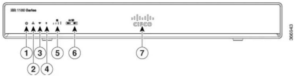
Figure1:C111xSeries-BezelView
text_image
IBM 1180 Ethernet ① ③ ⑤ ⑥ ② ④ ⑦ CISCO 366943| VPN2Status1 | |||
| GPS4WiFi3 | |||
| LTE Data/SIM6LTE Signal Intensity5 | |||
| Illuminated Cisco Logo7 |
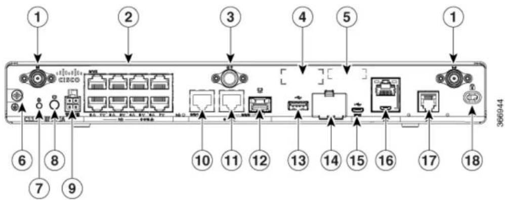
Figure2:C111x-8P-I/OView
text_image
1 2 3 4 5 1 6 7 8 9 366944| Ethernet Switch2LTE Antennas - Main and Diver | |||
| CLEI Label4GPS Connection3 | |||
| Grounding6Serial Number | |||
| 7 | 8Reset | ButtonSwitch | |
| 9 | 4-pin Power Connector | 10 | GE 0/0/1 |
| 11 | GE 0/0/0 - RJ45 | 12 | GE 0/0/0 - SFP |
| 13 | USB3.0 | 14 | Lower slot0Upper slot1 |
| 15 | LTE Provisioning Port | 16 | RJ45 / Micro USB Console |
| 17 | DSL | 18 | Kensington Lock Slot |
Product Identification Number (PID)19

Note
For more information on the Reset Button, refer to the Reset Overview section in the ISR 1000 Series Integrated Services Routers.
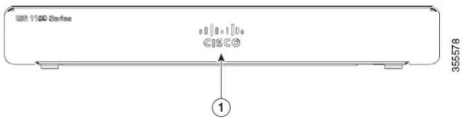
Figure3:C1101-4PISR-FrontView
text_image
IOUT 1100 Series CISCO 355578 ①Non-illuminated Cisco Logol
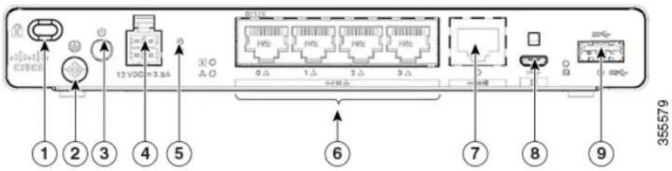
Figure4:C1101-4PISR-I/OView
text_image
1 2 3 4 5 12 VDD 3.8A 6 7 8 9 355579| Grounding2Kensington Lock Slot1 | |||
| 4-pin Power Connector4Power Switch3 | |||
| LAN: 0-46Reset Button5 | |||
| Micro USB Console8GE WAN7 | |||
| USB3.09 | |||
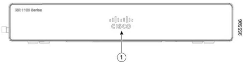
Figure5:C1101-4PLTEP-BezelView
text_image
XR 1100 Server CISCO ① 355586| Non-illuminated Cisco logol |
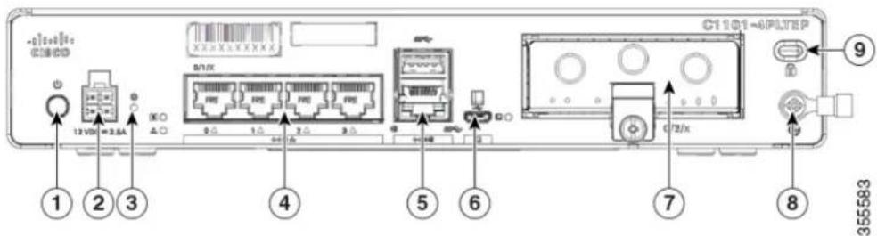
Figure6:C1101-4PLTEP-I/OView
text_image
C1101-6PLTEP ① ② ③ ④ ⑤ ⑥ ⑦ ⑧ ⑨ 12 VD = 2.6A A: 3 X: 4 5 X: 6 7 X: 8 355583| 4-pin Power Connector2Power Switch1 | |||
| LAN:0-44Reset Button3 | |||
| Micro-USB console Port6GE WAN5 | |||
| Grounding8Pluggable7 | |||
| Kensington Lock Slot9 | |||
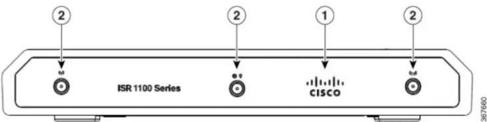
Figure7:C1109-2PLTE-BezelView
text_image
2 ISR 1100 Series 2 CISCO 1 2 367660| Non-illuminated Cisco logol | |
| Main and Diversity Antenna2 |
Figure8:C1109-2PLTE-I/OView

text_image
① ② ③ ④ ⑤ ⑥ ⑦ ⑧ ⑨ ⑩ I/O: I/O1 I/O2 367659| Grounding2Kensington Lock Slot1 | |||
| Power Switch4Reset Button3 | |||
| LAN: 0 & 164-pin Power Connector5 | |||
| Micro-USB console Port8GE WAN7 | |||
| Micro-SIM slots 0 and 110USB 3.09 |
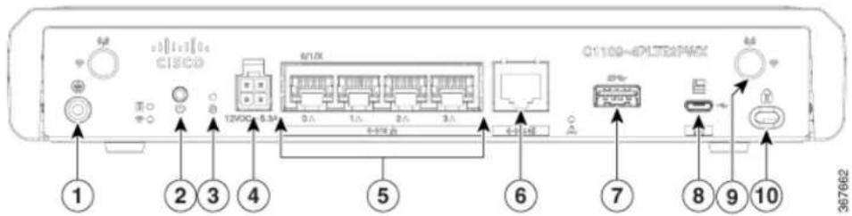
Figure9:C1109-4PLTE2PWX-I/OView
text_image
I2VDC C18CO 6/10X Q1100-4EPLTD2P46X 1 2 3 4 5 6 7 8 9 10 2676662| Power Switch2Grounding1 | |||
| 4-pin Power Connector4Reset Button3 | |||
| GE SWAN6LAN:0-4 | |||
| Micro-USB console Port8USB 3.07 | |||
| Kensington Lock Slot10LTE Antenna |
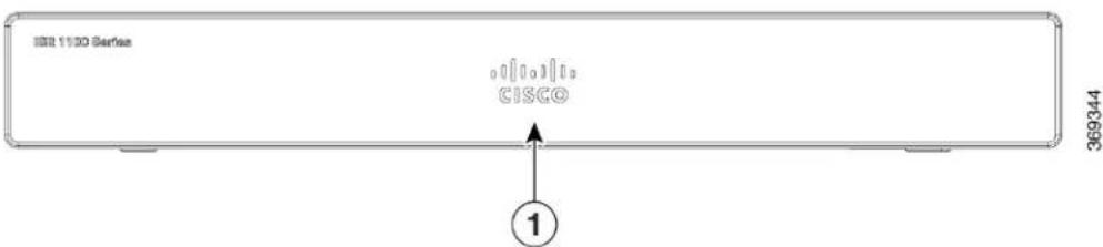
Figure10:C1121-4Px-BezelView
text_image
1100 Series CISCO ① 369344| Non-illuminated Cisco logo1 |
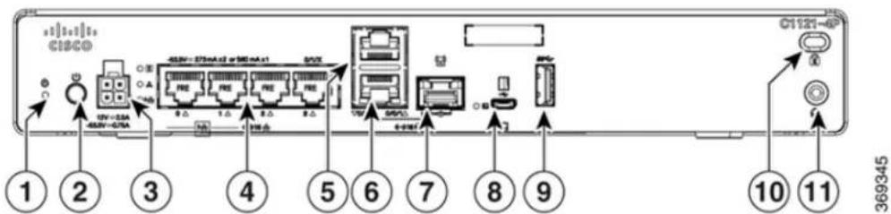
Figure11:C1121-4PI/OView
text_image
CISCO 1 2 3 4 5 6 7 8 9 10 11 369345| Power Switch2Reset Button1 | |||
| Ethernet Switch44-pin Power Connector3 | |||
| GE WAN 0/0/0 -RJ456RJ-45 Stacked Co | |||
| Micro-USB console8GE WAN 0/0/0 -SFP | |||
| Kensington Lock Slot10USB 3.09 | |||
| 11 | Grounding |
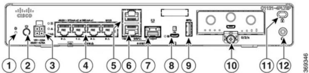
Figure12:C1121-4PLTEPI/OView
text_image
CISCO 1 2 3 4 5 6 7 8 9 10 11 12 369346| Power Switch2Reset Button1 | |||
| Ethernet Switch44-pin Power Connector3 | |||
| GE WAN 0/0/0 -RJ456GE 0/0/1 | |||
| Micro-USB console8GE WAN 0/0/0 -SFP | |||
| 10USB | Plugable | ||
| 12Kens | Groundingck Slot11 |
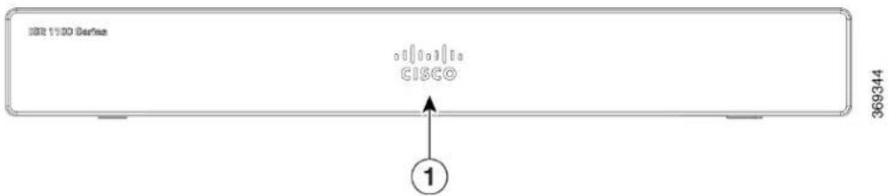
Figure13:C1121(X)-8P-BezelView
text_image
IBB 1100 Server CISCO ① 369344| Non-illuminated Cisco logo1 |
Figure14:C1121(X)-8PI/OView
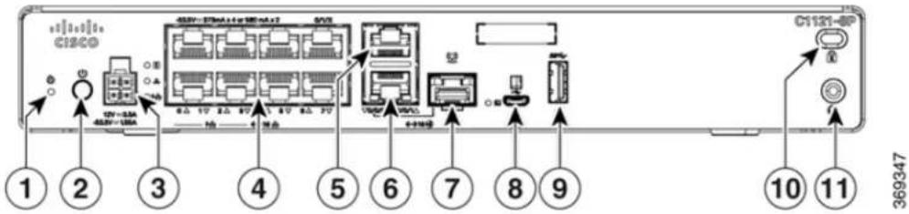
text_image
C12CD ① ② ③ ④ ⑤ ⑥ ⑦ ⑧ ⑨ ⑩ ⑪ 369347| Power Switch2Reset Button1 | |||
| Ethernet Switch44-pin Power Connector3 | |||
| GE WAN 0/0/0 -RJ456RJ-455 | |||
| Micro-USB console8GE WAN 0/0/0 -SFP | |||
| Kensington Lock Slot10USB 3.09 | |||
| 11 | Grounding |
Figure15:C1121-8PLTEPI/OView
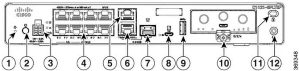
text_image
CISCO 1 2 3 4 5 6 7 8 9 10 11 12 369348| Power Switch2Reset Button1 | |||
| Ethernet Switch44-pin Power Connector3 | |||
| GE WAN 0/0/0 -RJ456GE 0/0/1 | |||
| Micro-USB console8GE WAN 0/0/0 -SFP | |||
| 10USB | Pable | ||
| Grounding12Kensington Lock Slot11 |
Figure16:C1121-8PLTEPWxBezelView
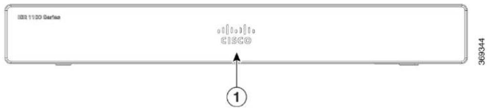
text_image
I/O 1100 Series CISCO ① 369344| Non-illuminated Cisco logol |
Figure17:C1121(X)-8PLTEPWI/OView
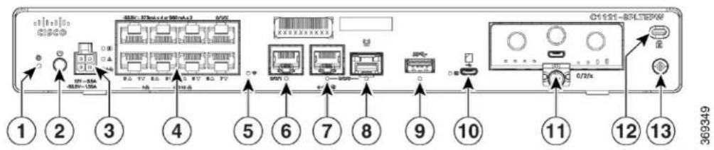
text_image
1 2 3 4 5 6 7 8 9 10 11 12 13 369349| Power Switch2Reset Button1 | |||
| Ethernet Switch44-pin Power Connector3 | |||
| GE 0/0/16Wi-Fi Status5 | |||
| GE WAN 0/0/0 -SFP8GE WAN 0/0/0 -R | |||
| 9 | 10Mic | 16SUSB.0console | |
| Kensington Lock1$lot12Pluggable | |||
| Grounding13 |
| Non-illuminated Cisco logol |
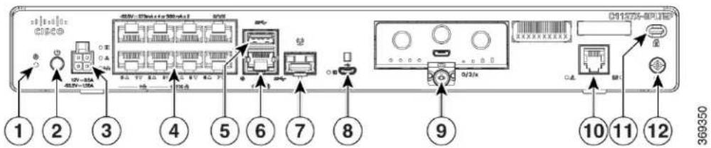
Figure19:C1127X-8PLTEPIOPanelView
text_image
① ② ③ ④ ⑤ ⑥ ⑦ ⑧ ⑨ ⑩ ⑪ ⑫ 369350| Power Switch2Reset Button1 | |||
| Ethernet Switch44-pin Power Connector3 | |||
| GE WAN 0/0/0 -RJ456RJ-455 | |||
| Micro-USB console8GE WAN 0/0/0 -SFP | |||
| DSL10Pluggable9 | |||
| 11 | 12Kensfingtundingck Slot | ||
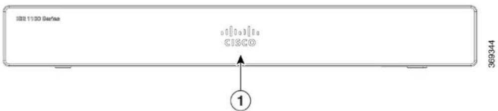
Figure20:C1128-8PLTEPBezelView
text_image
369344 CISCO ①| 1 | Non-illuminated Cisco logo |
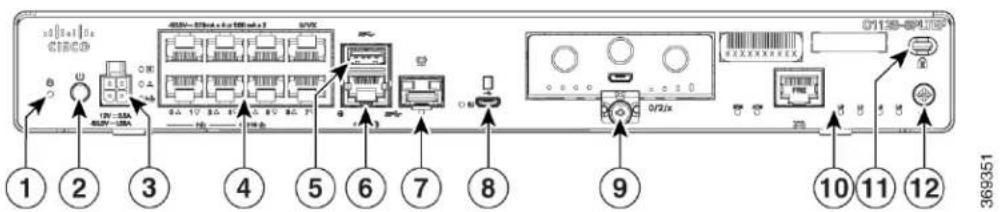
Figure21:C1128-8PLTEPI/OPanelView
text_image
1 2 3 4 5 6 7 8 9 10 11 12 369351| Power Switch2Reset Button1 | |||
| Ethernet Switch44-pin Power Connector3 | |||
| GE WAN 0/0/0 -RJ456USB 3.0 | |||
| Micro-USB console8GE WAN 0/0/0 -SFP | |||
| 10PluggSHOSL | |||
| 11 | 12KensignandLock Slot | ||
LEDIndicators
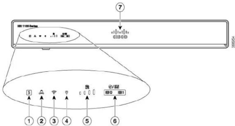
The following figures and table summarizes the LED indicators that are located in the bezel or chassis of C111x series.
Figure22:LEDIndicators-BezelSide
text_image
7 I/O 1100 Series C1308 45692 5 ① ② ③ ④ ⑤ ⑥ ⑦ ⑧/磁 I/O I/O| VPN2Status1 | |||
| GPS4WLAN3 | |||
| LTE DATA/SIM6LTE RSSI/Mode5 | |||
| Cisco Logo7 | |||
Figure23:LEDIndicators-I/OSide
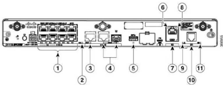
text_image
Diagram of a network device rear panel with labeled ports and connectors, showing numbered components from 1 to 11.| 1 | 1,3,5,7 at the bottom) | PoE LED2GE WAN Ports: 0-7 (0,2,4,6 at the to | |
| GE0 LED4GE1 LED3 | |||
| 5 | 6USBLED Console LED | ||
| 7 | 8USBMiconoUSB Console LED | ||
| 9 | CD LED | 10 | DATA LED |
Figure24:Cisco1121-4PxLEDIndicators
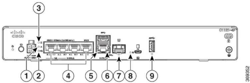
text_image
C120-4P 3 1 2 4 5 6 7 8 9 +12mA +1V 1V 2V 3V 4V 5V 6V 4.5V=370mA x 2x 500 mA x 1 +4mA +4V 369352| PoE LED2VPN1 | |||
| Ethernet Switch Ports 0-34Status3 | |||
| GE 0/0/1 LED6GE 0/0/0 RJ45 LED5 | |||
| Micro USB Console LED8GE 0/0/0 RJ45 | |||
| USB LED9 |
LED7
Figure25:Cisco1121-4PLTEPLEDIndicators
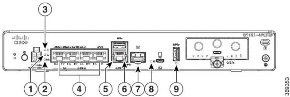
text_image
C160 Cisco 3 1 2 45.5V=870mA x 2 or 580 mA x 1 0/UX 4+1% 6+1% 8+1% 9 0/2/x C1121-4PLTEP 369353| PoE LED2VPN1 | |||
| Ethernet Switch Ports 0-34Status3 | |||
| GE 0/0/1 LED6GE 0/0/0 RJ45 LED5 | |||
| Micro USB Console LED8GE 0/0/0 RJ45 | |||
| USB LED9 |
LED7
Figure26:Cisco11x1(X)-8P/C11x1(X)-8PLTEPLEDIndicators
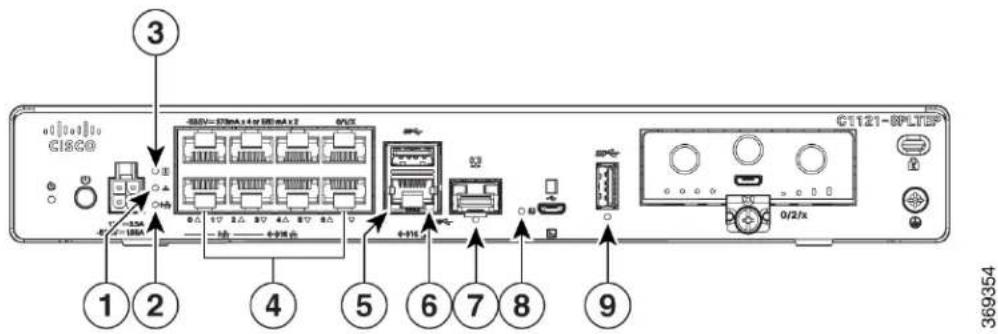
text_image
C1121-8PLTF 0/2/x 3 ③ ① ② ④ ⑤ ⑥ ⑦ ⑧ +12mA +16A +11A +11A +11A +11A +11A +11A +11A 369354| PoE LED2VPN1 | |||
| 4Status | Ethernet Switch Ports 0-7 (0,2,4,6 at the and 1,3,5,7 at the bottom) | ||
| GE 0/0/1 LED6GE 0/0/0 RJ45 LED5 | |||
| Micro USB Console LED8GE 0/0/0 RJ45 | |||
| USB LED9 |
top LED7
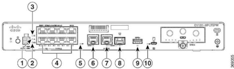
Figure27:Cisco11x1(X)-8PLTEPWxLEDIndicators
text_image
③ ① ② ④ ⑤ ⑥ ⑦ ⑧ ⑨ ⑩ C1121-BPLTSPW 369355| PoE LED2VPN1 | |||
| 4Status | Ethernet Switch Ports 0-7 (0,2,4,6 at the and 1,3,5,7 at the bottom) | ||
| GE 0/0/0 RJ45 LED6Wi-Fi5 | |||
| GE 0/0/0 SFP LED8GE 0/0/1 LED7 | |||
| Micro USB Console LED10USB LED9 |
top
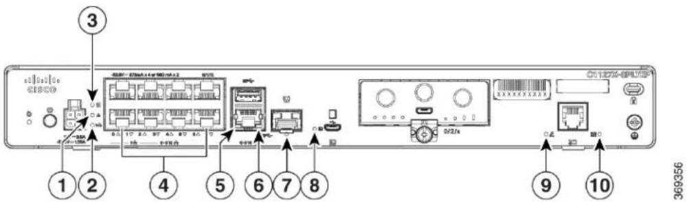
Figure28:Cisco1126(X)-8PLTEP/C1127(X)-8PxLTEPLEDIndicators
text_image
③ ① ② ④ ⑤ ⑥ ⑦ ⑧ 369356| PoE LED2VPN1 | |||
| 4Status | Ethernet Switch Ports 0-7 (0,2,4,6 at the and 1,3,5,7 at the bottom) | ||
| USB5 LED6GE 0/0/0 RJ45 LED5 | |||
| Micro USB Console LED8GE 0/0/0 SFP | |||
| CD LED9 |
top
LED7
The following table summarizes the LED indicators that are located in the bezel or chassis of the C111x sc
Table2:LEDIndicatorsforC111x
| ControlSourceDescription | |||
| Cisco Logo | Blue | Illuminated Cisco logo. Indicates router power is good. | Bezel side |
| STATUS (System Status) | Green and Amber | Steady Green - System operates normally. | Bezel side. All models. of not |
| Off—System is not out reset or BIOS image is loadable. | |||
| Blinking Amber — BIOS/Rommon is booting. | |||
| Steady Amber — BIOS/Rommon has completed booting, and the system is at the Rommon prompt or booting the platform software. |
LEDColorPoI
| ControlSourceDescriptionLEDColor | |||
| VPN OK | Bezel sideOff-No tunnel.Green | ||
| Steady On- At least one tunnel is up. | |||
| LTE RSSI/Mode | Green and Amber | Service | Bezel SideNo LEDs On-No |
| 1 LED On- RSSI is under -100dBm. | |||
| 2 LEDs On- Low RSSI, -99dbm <> -90dBm. | |||
| 3 LEDs On- Medium RSSI -89dBm <> -70dBm. | |||
| 4 LEDs On- High RSSI, > -69dBm. | |||
| Green- LTE | |||
| Amber- 3G | |||
| GPS | Bezel SideOff: GPS not configu | ||
| On: GPS configured | |||
| Blink: GPS Acquiring | |||
| WLAN | Green, Red, and Amber | operating condition with at least one wireless client association. | Bezel sideGreen- Normal |
| Red-Ethernet link is not operational or Ethernet failure. | |||
| Amber-Software upgrade is in progress. | |||
| Ethernet Switch GE LAN Ports, Non-PoE | I/O sideOff- No linkGreen | ||
| Steady On- link | |||
| Blink- TXD/RXD data | |||
| ControlSourceDescriptionLEDColorP | |||
| Ethernet Switch GE LAN Ports, with PoE | Green and Amber | powered, PD denied power, power delivery fault PoE administratively disabled.Green Steady On— link; if PoE device, power is enabled.Green Blink— TXD/RXD dataAmber - PoE Fault | I/O sideOff— No link,no device |
| GreenPoE OK | -53.5V PoE power supply connected and all powered port operating normally. | I/O sideGreen Steady On— | |
| Off — No -53.5V PoE power supply connected to router. | |||
| GE WAN Ports | I/O sideOff— No linkGreen | ||
| Steady On— link | |||
| Blink— TXD/RXD data | |||
| DSL CD | I/O SideOff— ShutGreen | ||
| Green Blink— Training, or no shut and cable disconnected. | |||
| Green Steady On— Trained | |||
| DSL Data | I/O SideOff— No DataActivityGre | ||
| Green Blink— TX/RX Data | |||
| Console | Green | enabled. | I/O sideGreen On— Console |
| GreenUSB Console | discovered. | I/O sideOff— No USB device | |
| On— USB device discovered. | |||
| ControlSourceDescriptionLEDCol | |||
| USB | Green | discovered. | I/O SideOff: No USB device |
| On: USB device discovered. |
Table3:LEDIndicatorsforC1101andC1109
| ControlSourceDescriptionColorLEC | |||
| Green+AmberPower | Off: No PowerGreenSteadyOn: Normal operationGreenBlink: Boot up phase or in ROM Monitor modeAmberSteadyonOr Blink: Some issues with the system. | I/OSystem Power Status | |
| GreenVPN OK | Off: No tunnelSteadyon:At least one tunnel is up | I/OVPN Status | |
| Ports | GreenEthernet Switch GE LANOff: No linkSteadyon: LinkBlink: TXD/RXD Data | I/OLink Activity | |
| GreenGE WAN Ports | Off: No linkSteadyon: LinkBlink: TXD/RXD Data | I/OLink ActivityControlSourceDescriptionColorLED | |
| (C1101-4PLTEPWzC1101-4PLTEPC1101-4PLTEPw) | Green and AmberLTE | DATA/SIMmodem with SIM switch-over capability)Off: Modem not up or modem up and no SIMAmberSteadyOn:Modem up, SIM installed but not active.GreenBlink: LTE data activity. | Bezel SideSingle LTE Modem (one |
| WLAN(C1101-4PLTEPWx) | & Amber; | I/OWLAN Functions3-color LED: C | |
| GreenUSB Console | OFF: USB console not activeON: USB console active | I/OUSB Console Status | |
| GreenUSB 3.0 | OFF: No USB device discoveredON: USB device discoveredUSB activity | I/OUSB 3.0 Status | |
ResetButton
The actuation of the Reset button is only recognized during ROMMON boot, that is, as the router comes to the ROMMON prompt.
The Reset button does not require much force to be actuated. The Reset button should be actuated only with a small implement such as the tip of a pen or a paper clip. When the Reset button is pressed at startup, the system LED turns green.
For more information, see the "Reset Overview" section of the Cisco 1100 Software Configuration Guide.
PowerSupply
C111x Series ISRs support PoE and PoE + power to endpoints. The product power specifications are as follow
• AC input voltage: Universal 100 to 240 VAC
• Frequency: 50 to 60 Hz
- Maximum output power: Up to 66W for non-PoE supply and upto 150W for PoE supply
- Optional PoE and PoE+
- Output voltage: +12VDC for system power and -53.5VDC for PoE power
SlotsandInterfaces
AboutSlots, Subslots, and Port Numbering
The Cisco 1100 series designates its interfaces using a 3-tuple notation that lists the slot, sub slot and p the format slot/sub-slot/port. The slot number is reserved for the mother board, which is "0". Each interf: type is allocated a sub slot and the port number is a unique port on the interface.
Table4: Slot, Bay, and Port Numbering
| InterfaceTypeSubslot | |
| Ethernet LAN0 | |
| Ethernet WAN1 | |
| 2 | LTE |
| 3 | DSL |
| WIFI4 |
SpecificationsofCisco1100SeriesIntegratedServicesRouters
For specifications on the Cisco 1100 Series ISRs, refer to the Cisco 1100 Series ISR Specifications document.
PeriodicInspectionandCleaning
We recommend that you periodically inspect and clean the external surface of the router is recommended to minimize the negative impact of environmental dust or debris. The frequency of inspection and cleaning dependent upon the severity of the environmental conditions, but we recommend a minimum once every months. Cleaning involves vacuuming router air intake and exhaust vents.

Note
Sites with ambient temperatures consistently above 25^ C or 77^ F and with potentially high levels of dust debris might require periodic preventative maintenance cleaning.
PeriodicInspectionandCleaning

text_image
CHAPTER 2PrepareforRouterInstallation
Before you install the Cisco 1100 Series Integrated Services Routers, you must prepare your site for the installation. This chapter provides pre-installation information, such as recommendations and requirements that should be considered before installing your router.
See the following sections to prepare for installation:
• Safety Recommendations, on page 23
• General Site Requirements, on page 24
- Rack Requirements, on page 25
• Safety Recommendations, on page 26
• Power Guidelines and Requirements, on page 26
• Network Cabling Specifications, on page 27
- Required Tools and Equipment for Installation and Maintenance, on page 29
SafetyRecommendations

Warning
IMPORTANT SAFETY INSTRUCTIONS
This warning symbol means danger. You are in a situation that could cause bodily injury. Before you won any equipment, be aware of the hazards involved with electrical circuitry and be familiar with standard practices for preventing accidents. Use the statement number provided at the end of each warning to locate its translation in the translated safety warnings that accompanied this device. Statement 1071
SAVE THESE INSTRUCTIONS

Warning
Ultimate disposal of this product should be handled according to all national laws and regulations. Staten 1040.
SafetyWithElectricity

Warning
Only trained and qualified personnel should be allowed to install or replace this equipment Statement 1030

Warning
Do not locate the antenna near overhead power lines or other electric light or power circuits, or where it come into contact with such circuits. When installing the antenna, take extreme care not to come into contact with such circuits, as they may cause serious injury or death. For proper installation and grounding of the antenna, please refer to national and local codes (for example, U.S.:NFPA 70, National Electrical Code, Article 810, Canada:Canadian Electrical Code, Section 54). Statement 1052
PreventElectrostaticDischargeDamage
Electrostatic discharge (ESD) can damage equipment and impair electrical circuitry. It can occur if electronic printed circuit cards are improperly handled and can cause complete or intermittent failures. Always follow ESD prevention procedures when removing and replacing modules:
- Ensure that the router chassis is electrically connected to ground.
- Wear an ESD-preventive wrist strap, ensuring that it makes good skin contact. Connect the clip to an unpainted surface of the chassis frame to channel unwanted ESD voltages safely to ground. To guard against ESD damage and shocks, the wrist strap and cord must operate effectively.
- If no wrist strap is available, ground yourself by touching a metal part of the chassis.

Caution
For the safety of your equipment, periodically check the resistance value of the anti-static strap. It should b between 1 and 10 megohms (Mohm).
GeneralSiteRequirements
This section describes the requirements your site must meet for the safe installation and operation of your router. Ensure that the site is properly prepared before beginning installation. If you are experiencing shutdown or unusually high errors with your existing equipment, the guidelines provided in this section can also help you isolate the cause of failures and prevent future problems.

Warning
Installation of the equipment must comply with local and national electrical codes. Statement 1074

Warning
Connect the Chassis to Earth Ground—To reduce the risk of electric shock, the chassis of this equipment needs to be connected to permanent earth ground during normal use. Statement 445

Warning
This product relies on the building's installation for short-circuit (overcurrent) protection. Ensure that the protective device is rated not greater than: 20A. Statement 1005

Warning
To prevent bodily injury when mounting or servicing this unit in a rack, you must take special precaution ensure that the system remains stable. The following guidelines are provided to ensure your safety:
- This unit should be mounted at the bottom of the rack if it is the only unit in the rack.
- When mounting this unit in a partially filled rack, load the rack from the bottom to the top with 1 heaviest component at the bottom of the rack.
- If the rack is provided with stabilizing devices, install the stabilizers before mounting or servicing the unit in the rack. Statement 1006.

Warning
To prevent the system from overheating, do not operate the devices in an area that exceeds the maximum recommended ambient temperature:
Statement 1047

Warning
For connections outside the building where the equipment is installed, the following ports must be connected through an approved network termination unit with integral circuit protection, LAN, PoE. Statement 1044.

Warning
To prevent airflow restriction, allow clearance around the ventilation openings to be at least: 1.75 in. (4.4 cm). Statement 1076.
SiteSelectionGuidelines
The Cisco 1100 Series ISRs require specific environmental operating conditions. Temperature, humidity, altitude, and vibration can affect the performance and reliability of the router. The following sections pro specific information to help you plan for the proper operating environment.
The Cisco 1100 Series ISRs are designed to meet the industry EMC, safety, and environmental standards described in the Regulatory Compliance and Safety Information for the Cisco 1100 Series ISR document.
RackRequirements
For the Cisco

Note
Rack requirements is applicable only for
The following information can help you plan your equipment rack configuration:
- Allow clearance around the rack for maintenance.
- Allow at least one rack unit of vertical space between routers; more clearance is required when stackin multiple Cisco
. Provide adequate heat removal mechanism to keep the surrounding air temperature well within the specified operating temperature condition.

Note More spacing may be required depending on the installation environment.
- Enclosed racks must have adequate ventilation. Ensure that the rack is not congested because each rout generates heat. An enclosed rack should have louvered sides and a fan to provide cooling air. Heat generated by the equipment near the bottom of the rack can be drawn upward into the intake ports of equipment above it.
- When mounting a chassis in an open rack, ensure that the rack frame does not block the intake or exports. If the chassis is installed on slides, check the position of the chassis when it is seated in the rack
SafetyRecommendations

Warning
IMPORTANT SAFETY INSTRUCTIONS
This warning symbol means danger. You are in a situation that could cause bodily injury. Before you work on any equipment, be aware of the hazards involved with electrical circuitry and be familiar with standard practices for preventing accidents. Use the statement number provided at the end of each warning to locate its translation in the translated safety warnings that accompanied this device. Statement 1071
SAVE THESE INSTRUCTIONS

Warning
Ultimate disposal of this product should be handled according to all national laws and regulations. Statement 1040.
PowerGuidelinesandRequirements
Check the power at your site to ensure that you are receiving power that is free of spikes and noise. Insta power conditioner, if necessary.
This section lists the power requirements for the Cisco
Table5:PowerRequirementsfor
| OutputRatedInputRatedPowerSource | ||
| (PWR-66W-AC-V2) | 12 VDC, 5.5A100-240V, 2A66W AC P | |
| (PWR-115W-AC) | 12V, 4.6A, -53.5V 1.12A100-240VAC, 2 | |
| (PWR-30W-AC) | 12V , 2.5A100-240 VAC, 1A30W AC | |
| (PWR-150W-AC) | 12V 5.5A, -53.5 1.5A100-240 VAC, 2A | |
| 66W DC Power Adapter(PWR-66W-I-DC) | 30 V DC input range) | 12 VDC, 5.5A24 V DC Nominal (19.7V |
NetworkCablingSpecifications
The following sections describe the cables and thee specifications required to install Cisco 1100 Series IS
ConsolePortConsiderations
The router includes an asynchronous serial console port. The console ports provide access to the router u a console terminal connected to the console port. This section discusses important cabling information to consider before connecting the router to a console terminal or modem.
Console terminals send data at speeds slower than modems do; therefore, the console port is ideally suited for use with console terminals.
EIA/TIA-232
Depending on the cable and the adapter used, this port appears as a DTE or DCE device at the end of cable. Only one port can be used at the same time.
The default parameters for the console port are 9600 baud, 8 data bits, 1 stop bit, and no parity. The c port does not support hardware flow control. For detailed information about installing a console terminal, the Connecting to a Console Terminal or Modem section.
For cable and port pinouts, see the Cisco Modular Access Router Cable Specifications document located Cisco.com.
USB Serial Console
The USB serial console port connects directly to the USB connector of a PC using a USB Type A to micro USB Type-B cable. The USB Console supports full speed (12Mb/s) operation. The console port does not support hardware flow control.

Note
Always use shielded USB cables with a properly terminated shield.
The default parameters for the console port are 9600 baud, 8 data bits, no parity, and 1 stop bit. For detail information about installing a console terminal, see the Connecting to a Console Terminal or Modem section on page 3-19.
For operation with a Microsoft Windows OS version older than Windows 7, the Cisco Windows USB Cons Driver must be installed on any PC connected to the console port. If the driver is not installed, prompts go you through a simple installation process.
The Cisco Windows USB Console Driver allows plugging and unplugging the USB cable from the console port without affecting Windows HyperTerminal operations. No special drivers are needed for Mac OS X or Linux.
Only one console port can be active at a time. When a cable is plugged into the USB console port, the R port becomes inactive. Conversely, when the USB cable is removed from the USB port, the RJ-45 port becor active.
Baud rates for the USB console port are 1200, 2400, 4800, 9600, 19200, 38400, 57600, and 115200 bps.

Note
4-pin micro USB Type-B connectors are easily confused with 5-pin micro USB Type-B connectors. Only the 5-pin micro USB Type-B is supported.
USBConsoleOSCompatibility
- Windows 10, Windows 8, Windows 7, Windows 2000, Window XP 32 bit, Windows Vista 32 bit
• Mac OS X version 10.5.4
• Redhat / Fedora Core 10 with kernel 2.6.27.5-117 - Ubuntu 8.10 with kernel 2.6.27-11
- Debian 5.0 with kernel 2.6
• Suse 11.1 with kernel 2.6.27.7-9
ConsolePortConsiderations
The router includes an asynchronous serial console port. The console ports provide access to the router using a console terminal connected to the console port. This section discusses important cabling information to consider before connecting the router to a console terminal or modem.
Console terminals send data at speeds slower than modems do; therefore, the console port is ideally suited for use with console terminals.
PrepareforRouterInstallation
Before you install the Cisco 1100 Series Integrated Services Routers, you must prepare your site for the installation. This chapter provides pre-installation information, such as recommendations and requirements that should be considered before installing your router.
See the following sections to prepare for installation:
EthernetConnections
The IEEE has established Ethernet as standard IEEE 802.3. The routers support the following Ethernet implementations:
- 1000BASE-T—1000 Mb/s full-duplex transmission over a Category 5 or better unshielded twisted-pai (UTP) cable. Supports the Ethernet maximum length of 328 feet (100 meters).
- 100BASE-T—100 Mb/s full-duplex transmission over a Category 5 or better unshielded twisted-pair (UTP) cable. Supports the Ethernet maximum length of 328 feet (100 meters).
- 10BASE-T—10 Mb/s full-duplex transmission over a Category 5 or better unshielded twisted-pair (UTP) cable. Supports the Ethernet maximum length of 328 feet (100 meters).
See the Cisco Modular Access Router Cable Specifications document at Cisco.com for information about Ethernet cables, connectors, and pinouts.
RequiredToolsandEquipmentforInstallationandMaintenance
You need the following tools and equipment to install and upgrade the router and its components:
- An ESD-preventive cord and a wrist strap
• A number 2 Phillips screwdriver - Phillips screwdrivers: small, 3/16-in. (4 to 5 mm) and medium 1/4-in. (6 to 7 mm). You might need when you install or remove modules, and when you remove the cover (when you upgrade the memory or other components)
- Screws that fit your rack
- A wire crimper
- A wire for connecting the chassis to an earth ground: AWG 14 (2 mm ^2 ) or larger wire
- An appropriate user-supplied UL or a CSA-certified ring terminal with an inner diameter of 1/4 in. 7 mm)

text_image
CHAPTER 3InstallandConnecttheRouter
This chapter describes how to install and connect Cisco 1000 Series Integrated Services Router (ISR) to and WAN networks.

Warning
Read the installation instructions before using, installing or connecting the system to the power source. Statement 1004
Installing the Cisco 1000 Series Integrated Services Routers involve these tasks:
- Unpack the Router, on page 31
- Set up Router on Desktop, Rack, or Wall, on page 31
- Connect Power Cable, on page 50
- Connect the Router to a Console, on page 52
- Connect WAN and LAN Interfaces, on page 56
- Configure the Router at Startup, on page 57
UnpacktheRouter
Unpack the router only when you are ready to install it. If the installation site is not ready, to prevent a damage, keep the chassis in its shipping container until you are ready to install.
The router, accessory kit, publications, and any optional equipment you order may be shipped in more than one container. When you unpack the containers, check the packing list to ensure that you have received listed items.
SetupRouteronDesktop,Rack,orWall
After unpacking, based on your requirements, you can set up a Cisco 1100 Series Integrated Services Rc (ISRs) on a desktop, a rack, or the wall.

Note
You can install external modules before or after mounting a router. However, if you choose to install the external modules after mounting the router on the rack or wall, ensure that you have optimal access to the back/front panel of the router.
For information on modules and Field Replaceable Units (FRUs), see the Install and Upgrade Modules and FRUs section.
Depending on the model, the available options for mounting a Cisco 1100 ISR are:
Table6:ModelsandMountingOptions
| MountingOptionsModel | |
| C111x and C1111X | Dscktop, Rack Mount, Wall Mount using Key-hole Slots, Wall Mount using-Din-Rail |
| Desktop, Wall Mount using Key-hole SlotsC1101-4P | |
| Desktop, Wall Mount using Key-Hole SlotsC1101-4PLTEPWx | |
| Desktop, Wall Mount using Key-Hole Slots,C1109-2PLTExx | |
| Desktop, Rack Mounting using Din-Rail Brackets, Under DeskC1121-4Px | |
| C1126(X)-8PLTEP | Desktop, Rack Mounting using Din-Rail Brackets, Under Desk |
| C1128(X)-8PLTEP | Desktop, Rack Mounting using Din-Rail Brackets, Under Desk |
If you choose to setup the router on a desktop, you can place the router on a desktop, bench top or on a
RackMount
Secure the rack mounting brackets on the sides of the chassis. You must first secure rack mounting bracket on the chassis before you set up the chassis on the rack.

Caution
Do not stack multiple Cisco 1000 ISRs when mounting the routers on a table top.

Note
When mounting Cisco 1000 ISRs on a rack, ensure that there is ample surrounding space. This ensures more heat removal, which in turn will enable the surrounding air temperature to stay within the specified operatin conditions.
AttachtheBracketsforC111x
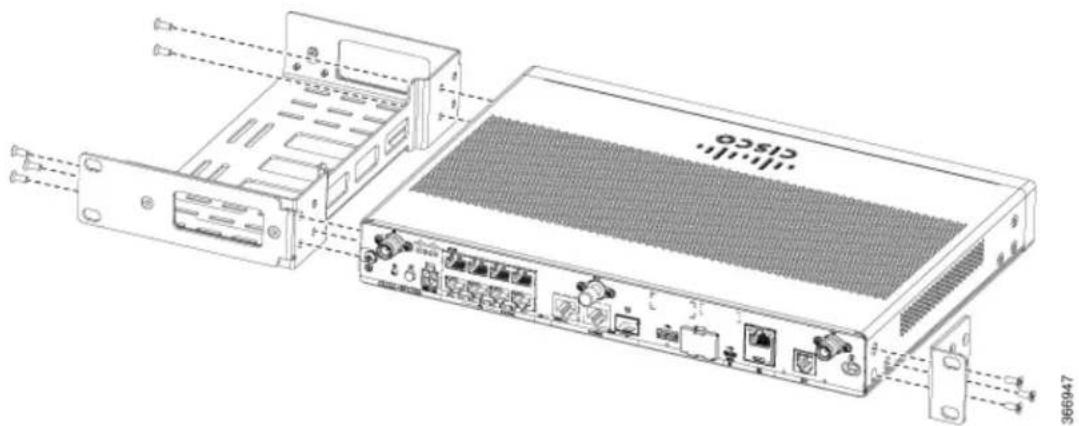
This procedure describes how to attach the brackets on the router chassis:
Step1 Secure the brackets to the router chassis (on the left) as shown in figure below:
Example:
Figure29:BracketInstallationforLeft-SideMounting-C111x
text_image
Technical diagram of a network device showing internal components and labeled ports, including a CISCO-branded base and external connectors.Step2 Similarly, secure the brackets on the right-side of the chassis for mounting the router.
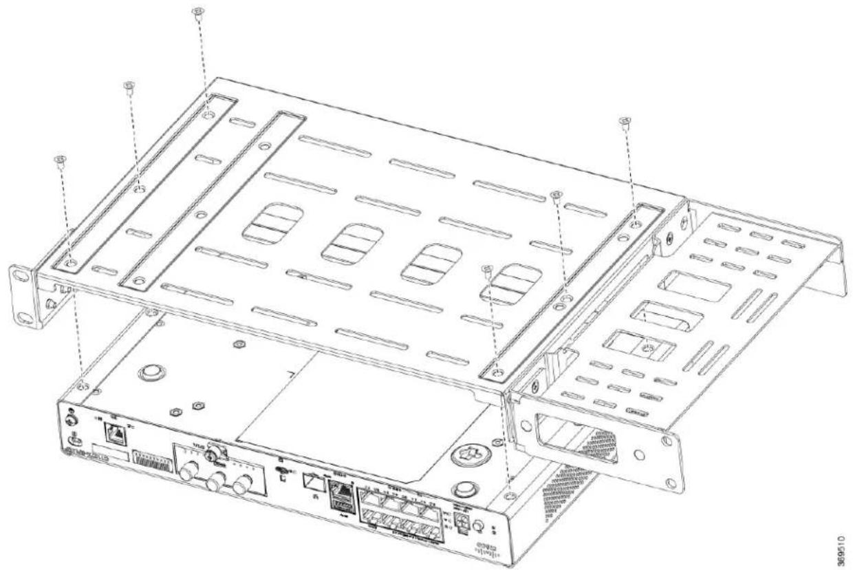
AttachtheRackMountingBracketsforC112x
This procedure describes how to attach the brackets on the router chassis:
Step1Remove the 6 screws from the bottom of the chassis.
Step2Place the platform into the bottom tray.
Step3Secure the original screws from the bottom side of the tray.
Example:
Figure30:BracketInstallationforC1121-4Px,C1126-8PLTEPandC1128-8PLTEP
text_image
Technical diagram of a server rack with labeled ports and connectors, showing internal structure and mounting points.MounttheRouter
Before mounting the router on to the rack, refer to the following safety warning statements:

Warning
To prevent airflow restriction, allow clearance around the ventilation openings to be at least: 1.75 in. (4.4 cm). Statement 1076.

Warning
• To prevent bodily injury when mounting or servicing this unit in a rack, you must take special precautions to ensure that the system remains stable. The following guidelines are provided to ensure your safety:
- This unit should be mounted at the bottom of the rack if it is the only unit in the rack.
- When mounting this unit in a partially filled rack, load the rack from the bottom to the top with the heaviest component at the bottom of the rack.
- If the rack is provided with stabilizing devices, install the stabilizers before mounting or servicing the unit in the rack. Statement 1006.
Procedure
| PurposeCommandorAction | ||
| Step1 | To install the router, use the screws provided with the accessory kit to secure the router when you mount it on the rack. |
MounttheRouterunderaDeskoraShelf
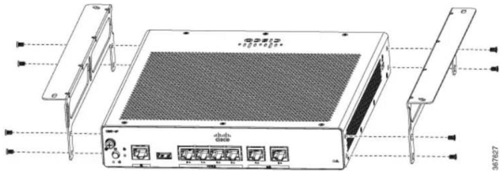
Installing the router under a desk requires an optional bracket kit that is not included with the router. It contains the rack-mount brackets and screws to secure the brackets to the router and the underside of the You can order these kits from your Cisco representative. This procedure describes how to mount router to a desk or a shelf.
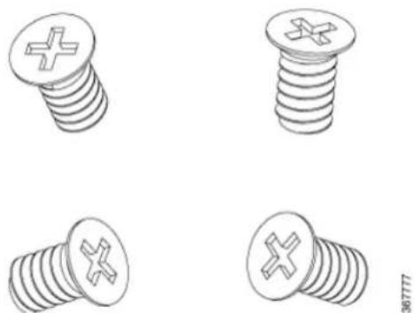
Step 1 Attach a bracket to one side of the router using the flat-head screws. Follow the same steps to attach the second bracket to the opposite side.
Figure31: Attaching BracketstotheRouter
text_image
CD8132 CD8132 CD8132 CD8132 CD8132 CD8132 CD8132 CD8132 CD8132 CD8132 CD8132 CD8132 CD8132 CD8132 CD8132 CD8132 CD8132 CD8167627Figure32: Flat-headMachineScrews
natural_image
Four technical illustrations of screw head designs with cross symbols, shown from different angles (no text or labels)Figure33:RouterwithBracketsAttached

natural_image
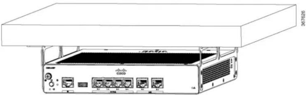
Technical line drawing of an industrial rack-mounted server unit with ventilation grilles and ports (no text or symbols)Step 2 After the brackets are attached, drill a 2 mm hole under the desk and insert the wooden screws provided. Mount the router under the desk or shelf using the pan-head wood screws).
Figure34:MountingtheRouterunderaDeskorShelf
natural_image
Line drawing of a Sony 367626 industrial rack unit with ports and connectors (no text or symbols on the device itself)Figure35:Pan-headWoodScrews

natural_image
Four different types of screw fasteners shown in line drawings (no text or symbols)MountRouterusingDINRailBrackets
The router is shipped with DIN Rail brackets that are to be secured on the bottom side of the chassis. You chassis installation must allow unrestricted airflow for chassis cooling.
To attach the DIN Rail brackets to the router chassis, use the PHMS screws and the plastic spacers provided for a bracket.
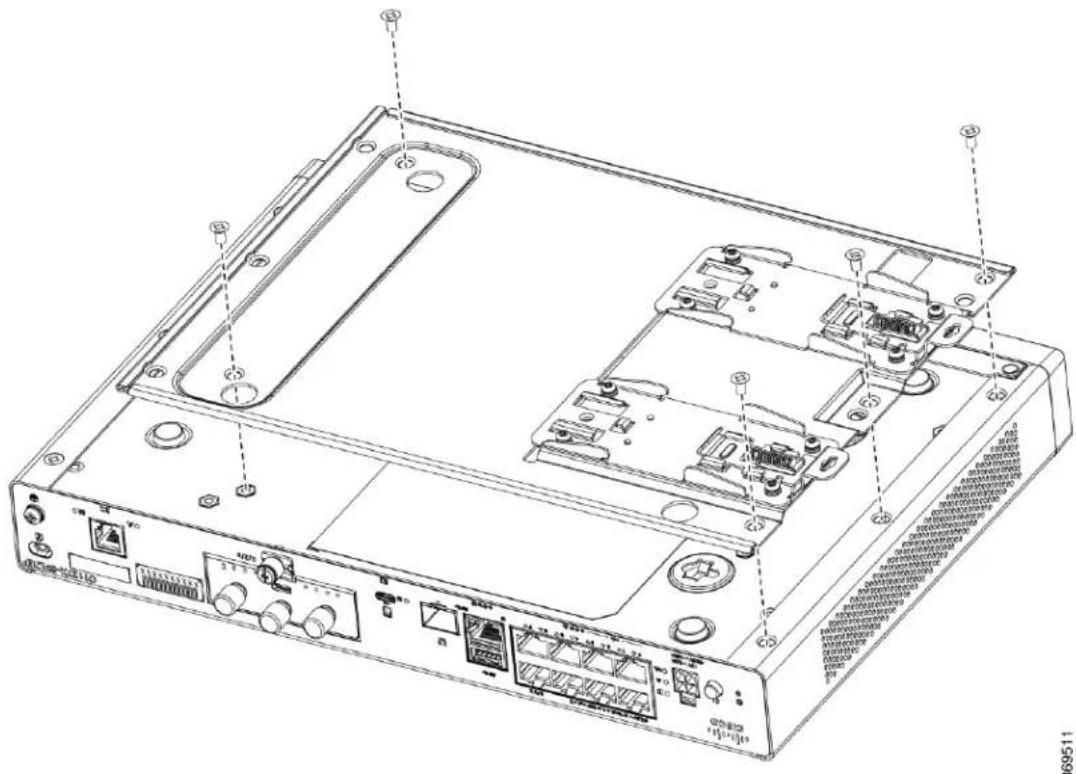
AttachDin-RailBracketsonC112x
This procedure describes how to attach the brackets on the router chassis:
Step1Remove the 3 bottom screws from the chassis.
Step2Place the din-rail tray assy on the bottom side of the chassis.
Step 3 Secure the original screw from bottom side of tray, leverage the existing chassis screws to secure the din rail mounting bracket from the bottom of the chassis.
Step4Take the other two screws to secure the din-rail trail assy
Example:
Figure36: Attaching Din Rail Brackets for C1121-4Px, C1126-8 PLTEP and C1128-8 PLTEP
text_image
Technical diagram of a device rear panel with labeled ports and connectorsWallMounttheRouter
Depending on the models of the Cisco 1100 Series Integrated Services Routers (ISRs), the tasks for mountir the router chassis on the wall may vary.

Warning
Read the wall-mounting instructions carefully before beginning installation. Failure to use the correct hardware or to follow the correct procedures could result in a hazardous situation to people and damage to the system Statement 378.

Note
The recommended clearance when a router is horizontally mounted is 1.5 inches on both sides for clearance and 1.75 inches on top. I/O side clearance is needed as it is required to access the cable connections. Clear is not required on the backside (opposite side from I/O face) unless mounting on a DIN Rail. Clearance is required to attach and mount the DIN rail bracket.
There are two ways to mount a router on the wall, using Key-hole Slots and DIN Rail Brackets.
WallMountUsingKey-holeSlots
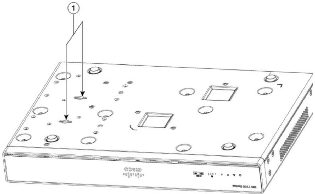
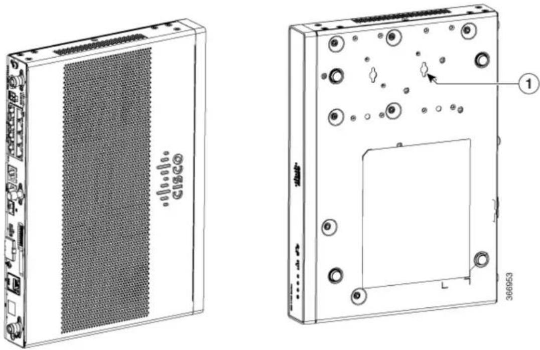
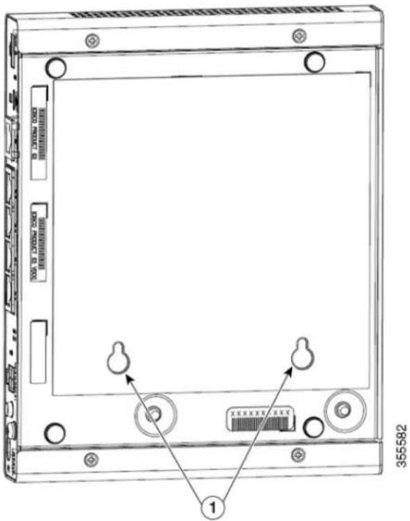
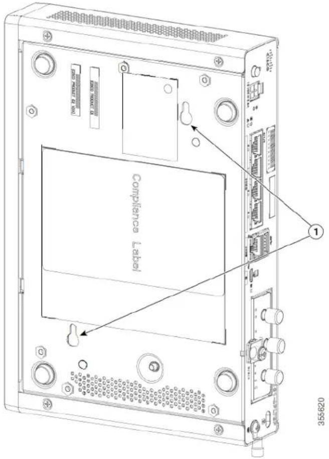
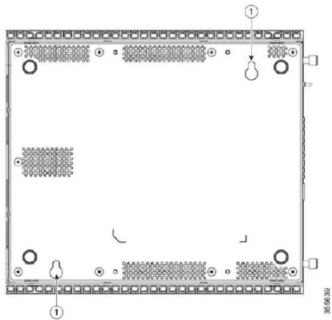
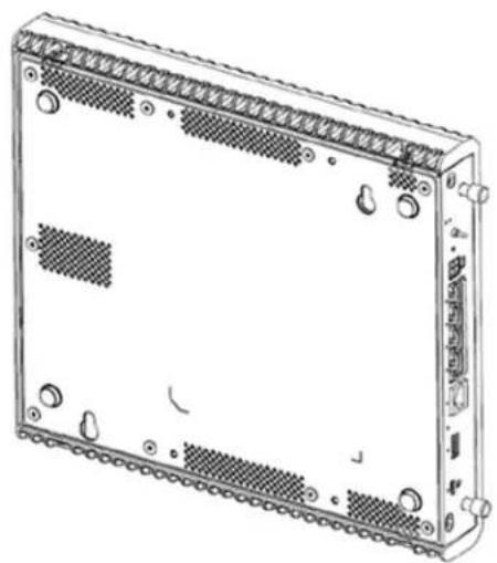
The Cisco 1100 Series Integrated Services Routers (ISRs) have key-hole slots at the bottom of the chassis f mounting on a wall or any vertical surface.

Note
Do not mount the router with the output ports facing downwards. For the C111x series, ensure that the cab are placed on the sides.

Note
When choosing a location for wall mounting the router, consider cable limitations and wall structure.

Note
To attach a router to the wall stud, each bracket should have one number10 wood screw (pan-head) with number10 washers, or two number10 washer-head screws. The screws must be long enough to penetrate at least 1.5 inches (38.1 mm) into the supporting wood or metal wall stud.

Note
For hollow-wall mounting, each bracket requires two wall anchors with washers. Wall anchors and washers must be size number 6 (pan-head). Route the cables so that they do not put a strain on the connectors or mounting hardware.
Figure37: WallMountUsingKey-holeSlots-C111x
text_image
1 CISCO 100 1:100 GB/MB| Key-hole slots1 |
Figure38: WallMountOrientation-C111x
natural_image
Technical line drawings of a server rack and its internal components, showing front and side views with no visible text or symbols.| Key-hole slots1 |
Figure39: Wallmountusingkey-holeslots-C1101-4P
text_image
355582 1| 1 | Key-hole slotsKey-hole slots-spacing: 3.024in (76.81mm) |
Figure40: Wallmountusingkey-holeslots-C1101-4PLTEP
text_image
File PRICE: $1.00 SAR SAR Compliance Label 355620| 1 | Key-hole slotsHorizontal spacing: 3.100in (78.74mm)Vertical spacing: 5.758inin (146.25mm) |
Figure41: Wallmountusingkey-holeslots-C1109-2P
text_image
Technical diagram of a server rack with labeled components and status indicators| 1Key-hole slots | Horizontal spacing: 7.302in (185.47mm)Vertical spacing: 7.430in (188.72mm) |
Figure42: Wallmountusingkey-holeslots-C1109-4PLTEP
natural_image
Technical line drawing of a rectangular electronic device with multiple ports and mounting holes (no text or symbols)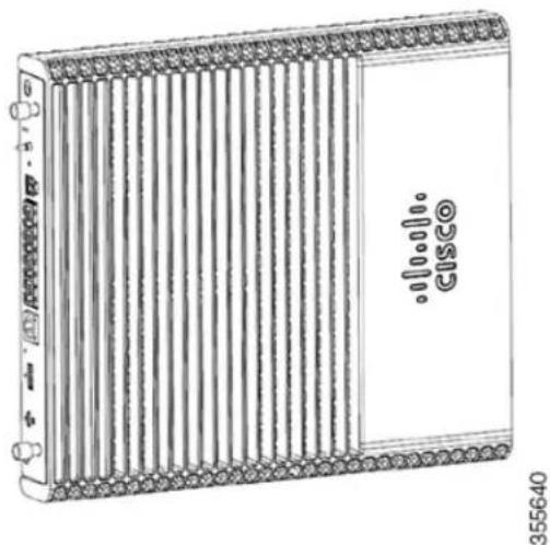
natural_image
Line drawing of a server rack with ventilation slots and a Cisco logo (no text or symbols on the diagram itself)| 1 | Key-hole slotsHorizontal spacing: 3.100in (78.74mm)Vertical spacing: 5.758inin (146.25mm) |
Figure43: Wallmountusingkey-holeslots-C1126-8PLTEP
natural_image
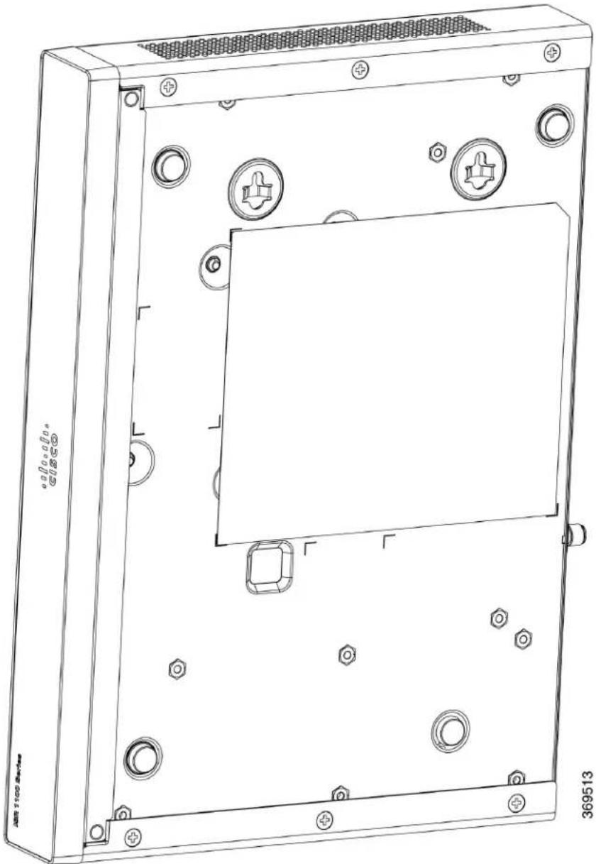
Technical line drawing of a device casing with mounting holes and circular components (no text or symbols)| 1 | Key-hole slotsHorizontal spacing: <>Vertical spacing: <> |
WallMountusingDINRailBrackets
The router is shipped with DIN Rail brackets that are to be secured on the bottom side of the chassis. chassis installation must allow unrestricted airflow for chassis cooling.

Note
Wall mount using DIN Rail brackets is applicable only for C111x.
To attach the DIN Rail brackets to the router chassis, use the PHMS screws and the plastic spacers provided for a bracket.
Figure44:DINRailBracketInstallation-C111xandC111X

natural_image
Abstract red pixelated geometric shape on white background, framed by gray border (no text or symbols)| Screws1 | |
| DIN Rail Brackets2 |
Figure45: Orientation of DIN Rail Brackets
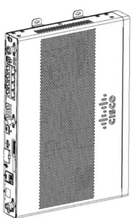
natural_image
Line drawing of a rectangular electronic device with a mesh panel and mounting tabs (no text or symbols)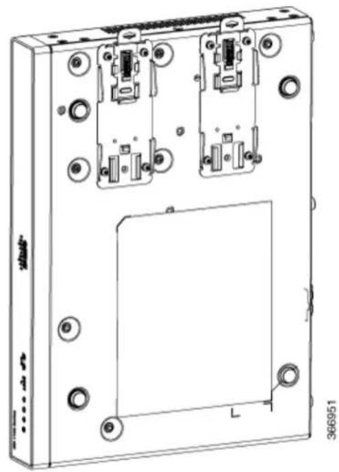
natural_image
Technical line drawing of a device rear panel with mounting holes and internal components (no text or symbols)Figure46:DINRailBracketsandMount
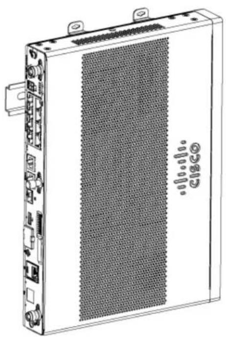
natural_image
Line drawing of a server rack unit with ventilation grating and ports (no text or symbols visible)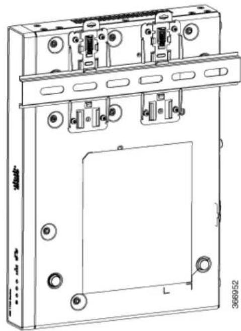
natural_image
Technical line drawing of a mechanical or electronic device with mounting holes and a central panel (no text or symbols)Note Do not over-torque the screws. The recommended torque is 8 to 10 inch-lbf (0.9 to 1.1 N-m).
ChassisGrounding

Warning
Connect the Chassis to Earth Ground—To reduce the risk of electric shock, the chassis of this equipment needs to be connected to permanent earth ground during normal use. Statement 445

Warning
Only trained and qualified personnel should be allowed to install or replace this equipment Statement 1030
After you set up the router, connect the chassis to a reliable earth ground; the ground wire must be installed in accordance with local electrical safety standards. For safety information on grounding the chassis, refer to the chassis ground connection procedures.
- For grounding the chassis, use a copper wire of size of 14 AWG (2 mm ^2 ) and the ground lug. These are not a part of the accessory kit.
- Use the UNC 6-32 screws, which have a length of about 0.25 inches.
To install the ground connection for your router, perform these steps:
1.Strip one end of the ground wire to the length required for the ground lug or terminal.
- For the ground lug—approximately 0.75 inch (20 mm)
-
For user-provided ring terminal—as required
-
Crimp the ground wire to the ground lug or ring terminal, using a crimp tool of the appropriate size.
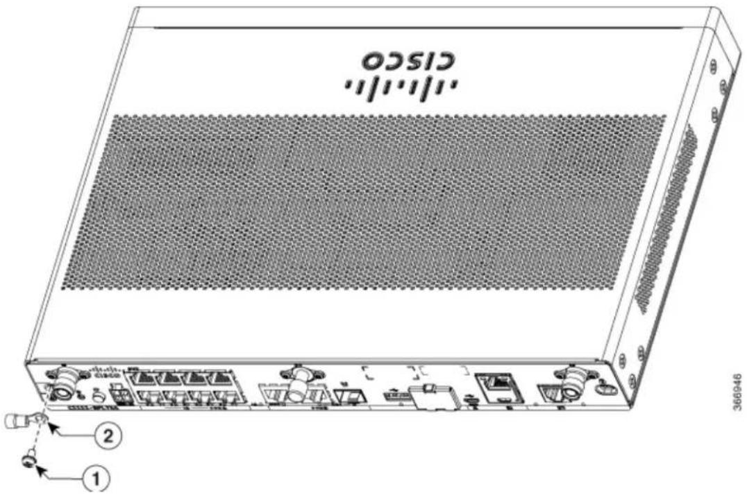
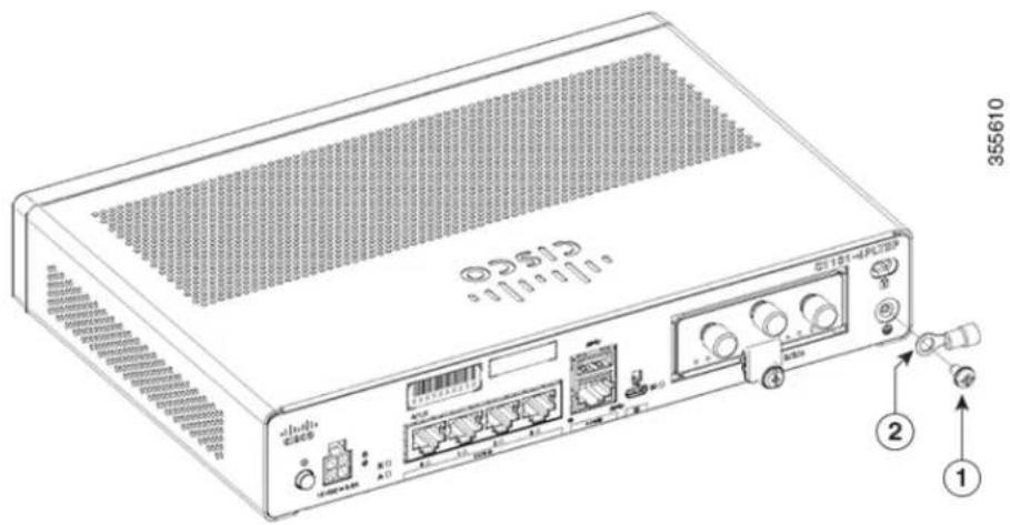
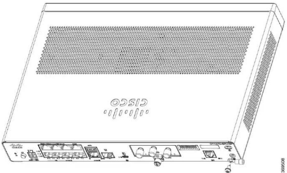
- Attach the ground lug or ring terminal to the chassis as shown in the below figures. The screw for the ground lug is provided. Tighten the screw; the recommended torque is 8 to 10 inch-lbf (0.9 to 1.1 N-m
Figure47: ChassisGroundConnection-Cisco111x
text_image
CISCO 366946| Screw (UNC 6-32)1 | |
| Ground Lug2 |
Figure48: ChassisGroundConnection-Cisco1101-4PLTEP
text_image
355610 ① ② ③ ④ ⑤ ⑥ ⑦ ⑧ ⑨ ⑩ ⑪ ⑫ ⑬ ⑭ ⑮ ⑯ ⑰ ⑱ ⑲ ⑳ ㉑ ㉒ ㉓ ㉔ ㉕ ㉖ ㉗ ㉘ ㉙ ㉚ ㉛ ㉜ ㉝ ㉞ ㉟ ㉳ ㉟ ㉟A A1 A2 A3 A4 A5 A6 A7 A8 A9 A10 A11 A12 A13 A14 A15 A16 A17 A18 A19 A20 A21 A22 A23 A24 A25 A26 A27 A28 A29 A30 A31 A32 A33 A34 A35 A36 A37 A38 A39 A40| Screw (UNC 6-32)1 | |
| Ground Lug2 |
Figure49: ChassisGroundConnection-Cisco1121X-8PLTEP
text_image
GISCO 08/06/2013| Screw (UNC 6-32)1 | |
| Ground Lug2 |
ConnectPowerCable
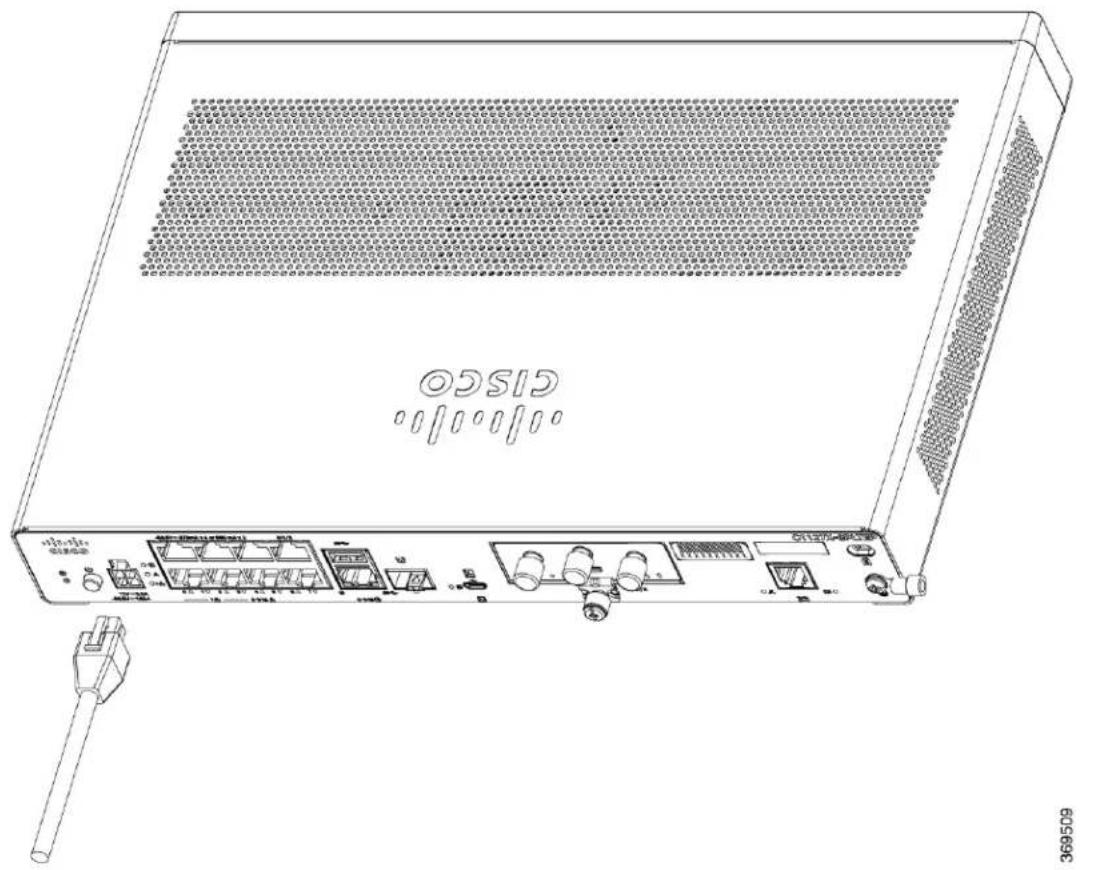
Power supply of the Cisco 1000 Series ISRs is an external AC to DC power adapter. The external DC power connector plugs into the router's 4 points power connector.
Figure50:PowerCableforC111x

natural_image
Abstract geometric pattern with red pixelated X shape inside a black square frame (no text or symbols)| Power Cable1. |
Figure51:PowerCableforC1127-8PLTEP
text_image
CISCO 369509| Power Cable1. |
ConnecttheRoutertoaConsole
The C111x Series ISR has an asynchronous serial port. This port provides administrative access to the route through a console terminal or a PC.
Figure52:ConsoleAdapterforC1101-4PLTEP

text_image
355619 355619| Micro USB to RJ45 console adapter1. |
Figure53: ConsoleAdapterforC1127X-8PLTEP
natural_image
Line drawing of a network switch device with ports and connectors, no text or symbols present| Micro USB to RJ45 console adapter1. |
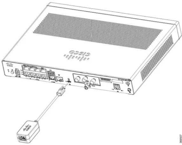
Use the USB or RJ-45 console port on the router to access the Cisco Internet Operating System (IOS-XE) command line interface (CLI) on the router and perform configuration tasks. A terminal emulation program is required to establish communication between the router and a PC.
To configure the router through the Cisco IOS CLI, you must establish a connection between the router cons port and either a PC or a terminal.
Use the following cables and adapters to establish a local or remote connection.
Table7: LocalandRemoteConnections
| ActionCablePortType | ||
| Serial (RJ-45) | C111x,C1111X: RJ-45 Serial console cableCAB-CON-USB (Serial USB to RJ-45 serial cable) | Connecting to the Serial Port w Microsoft Windows |
| C110x: CAB-CON-USBRJ45Serial (USB) |
ConnecttotheSerialPortwithMicrosoftWindows
To establish a physical connectivity between the router and a PC, you need to install a Microsoft Windows USB.
Use the USB Console cable plugged into the USB serial port to establish this connection.
- Connect the end of the console cable with the RJ-45 connector to the light blue console port on the router.
2.OR
Connect a USB 5-pin micro USB Type-B to the USB console port. If you are using the USB serial port for the first time on a Windows-based PC, install the USB driver.

Note
You cannot use the USB port and the EIA port concurrently. When the USB port is used it takes priority the RJ-45 EIA port.
- Connect the end of the cable with the DB-9 connector (or USB Type-A) to the terminal or PC. If your terminal or PC has a console port that does not accommodate a DB-9 connector, you must provide an appropriate adapter for that port.
- Start a terminal emulator application to communicate with the router. Configure the software with the following parameters:
• 9600 baud
- 8 data bits
- no parity
- 1 stop bit
- no flow control
ConnecttotheConsolePortwithMacOSX
This procedure describes how to connect a Mac OS X system USB port to the console using the built X Terminal utility.
Step1 Use the Finder to go to Applications > Utilities > Terminal.
Step2Connect the OS X USB port to the router.
Step3Enter the following commands to find the OS X USB port number
Example:
macbook:user$ cd /dev
macbook:user$ ls -ltr /dev/*usb*
crw-rw-rw- 1 root wheel 9, 66 Apr 1 16:46 tty.usbmodem1a21 DT-macbook:dev user$
Step4Connect to the USB port with the following command followed by the router USB port speed
Example:
macbook:user$ screen /dev/tty.usbmodem1a21 9600
TodisconnecttheOSXUSBconsolefromtheTerminalwindow
Enter Ctrl-a followed by Ctrl-\
ConnecttotheConsolePortwithLinux
This procedure shows how to connect a Linux system USB port to the console using the built in Linux' utility.
Step1Open the Linux Terminal window.
Step2Connect the Linux USB port to the router.
Step3Enter the following commands to find the Linux USB port number
Example:
root@usb-suse# cd /dev
root@usb-suse /dev# ls -ltr *ACM*
crw-r--r-- 1 root root 188, 0 Jan 14 18:02 ttyACMO
root@usb-suse /dev#
Step4Connect to the USB port with the following command followed by the router USB port speed
Example:
root@usb-suse /dev# screen /dev/ttyACM0 9600
TodisconnecttheLinuxUSBconsolefromtheTerminalwindow
Enter Ctrl-a followed by : then quit
ConnectWANandLANInterfaces
This section describes how to connect WAN and LAN interface cables. Before you connect the interface cables, refer to the following warning statements:

Warning
Never install telephone jacks in wet locations unless the jack is specifically designed for wet locations. Statement 1036.

Warning
Never touch uninsulated telephone wires or terminals unless the telephone line has been disconnected at the network interface. Statement 1037.

Warning
For connections outside the building where the equipment is installed, the following ports must be connected through an approved network termination unit with integral circuit protection, LAN, PoE. Statement 1044.

Warning
Avoid using or servicing any equipment that has outdoor connections during an electrical storm. There may be a risk of electric shock from lightning. Statement 1088.
PortsandCabling
This section summarizes typical WAN and LAN connections for Cisco 1100 Series ISRs. The connections summarized here are described in detail in the Cisco Modular Access Router Cable Specifications document on cisco.com.
Table8: WANandLANConnections
| PortorConnection | 1 | CableConnectionPortType,Color | |
| RJ-45, yellowEthernet switch | Ethernet hub or Ethernet switch | Category 5 or higher Ethernet | |
| Gigabit Ethernet SFP, optical | LC, color according optical wavelength | t000BASE-SX, -LX, -LH-ZX, -CWDM | Optical fiber as specified applicable data sheet |
| copper | Category 5, 5c, 6 UTP1000BASE-TR | ||
| (VDSL2 / ADSL2/2+) | RJ-11 telephone kDSPOTS or ISDN |
^1 Cable color codes are specific to Cisco cables.
ConnectionProceduresandPrecautions
After you have installed the router chassis, perform these steps to connect the WAN and LAN interfaces
- Connect each WAN and LAN to the appropriate connector on the chassis.
- Position the cables carefully so that you do not strain the connectors.
- Organize cables in bundles so that cables do not intertwine.
- Inspect the cables to make sure that the routing and bend radius is satisfactory. If necessary, reposi the cables.
• Install cable ties in accordance with site requirements.
ConfiguretheRouteratStartup
After installing the router and connecting the cables, you can configure the router with basic configuratio For more information on how to configure the router, see the Cisco 1100 Series Software Configuration Guide.

text_image
CHAPTER 4InstallandUpgradeInternalModulesandField ReplaceableUnits
The Cisco 1100 Series Integrated Services Routers have internal modules and field-replaceable units (FRU that can be quickly and easily removed and replaced without having to send the entire router for repair.
This section describes how to install the internal modules and FRUs in the Cisco 1100 Series ISRs. The information is contained in the following sections:
- Replace the Chassis Covers for C111X and C1111x, on page 59
• External Modules, on page 62
• Install and Remove Small Form Pluggable Modules, on page 63
• Install an LTE Pluggable Module, on page 64
ReplacetheChassisCoversforC111XandC1111x
To access the internal modules on the router, you must first remove the chassis cover. See the instruction below on how to remove and later replace the chassis cover on the routers.

Warning
Only trained and qualified personnel should be allowed to install, replace or service this equipment. State 1030
Cisco 1100 Series ISRs have removable covers. Do not run the routers with the cover off. Doing so car the router to overheat very quickly.
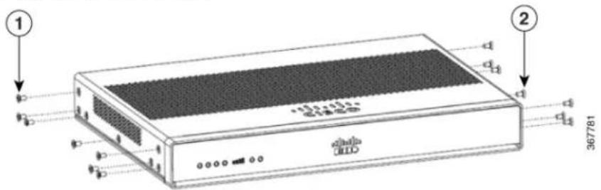
Use a number-2 Phillips screwdriver to perform the following tasks.
RemovetheCover
To remove the cover, do these
text_image
① ② 367781steps:
Remove the 14 screws from either side of the cover.1 and 2
text_image
367782 367780Step 1 Read the Safety Warnings and disconnect the power supply before you perform any module replacement.
Step2 Confirm the router is turned off and disconnected from the power supply.
Step 3 Disconnect all port cables connected to the router. Ensure that you do not work on the router with cables still attached to the router in the event of lightning or surges.
Step4 Installer to disconnect all cables connected to the system.
Step5 Place the chassis on a flat surface.
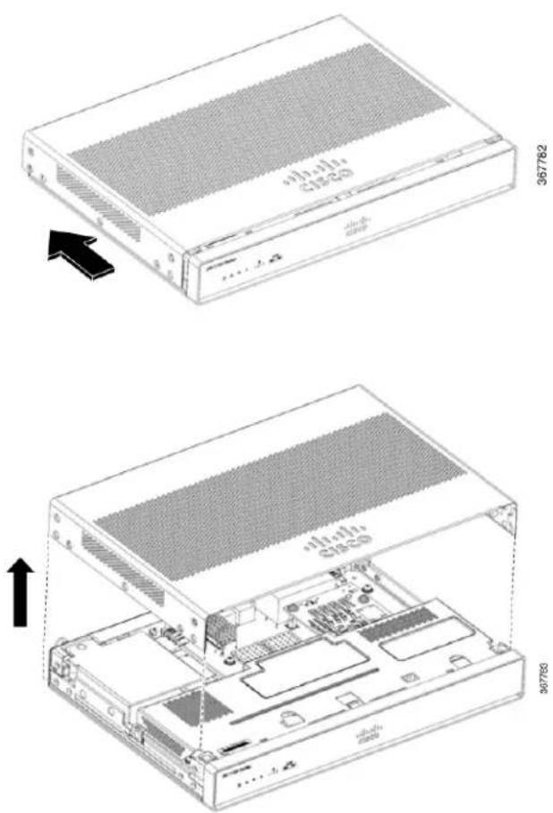
Step6Remove the 14x cover screws on the two sides of the router cover. See figure.
Step7Slide the cover from bezel side to I/O side until it stops.
Step8Pull the cover vertically to disengage from the chassis.
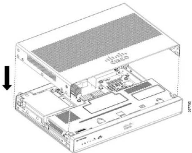
ReplacetheCover
To replace the cover, do these steps:

Warning
The covers are an integral part of the safety design of the product. Do not operate the unit without the installed. Statement 1077.
text_image
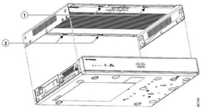
Technical diagram of an electronic device showing front and back views with labeled components and internal structure.Replace the 14 screws on either side of the cover.1 and 2
natural_image
Technical diagram of an open computer chassis showing internal components and a ventilation grille (no text or symbols)Step 1 Read the Safety Warnings and disconnect the power supply before you perform any module replacement.
Step2 Confirm the router is turned off and disconnected from the power supply.
Step 3 Disconnect all port cables connected to the router. Ensure that you do not work on the router with cables still attached to the router in the event of lightning or surges.
Step4Place the chassis on a flat surface.
Step 5 Align hooks on the cover to slots on the chassis base and lower the cover onto chassis base.
Step6Slide the cover from the I/O side to the bezel side
Step7 Install the fourteen screws on both sides of the chassis. Torque to 6-8 in-lbs.
ExternalModules
The Cisco 1100 Series Integrated Services Routers have external modules and field-replaceable units (FRUs) that can be quickly and easily removed and replaced without having to send the entire router for repair.
This section describes how to install external modules and FRUs in the Cisco 1100 Series ISRs. The informat is contained in the following sections:

Warning
Only trained and qualified personnel should be allowed to install, replace or service this equipment. Statement 1030.
LocateExternalSlotsforModules
This section describes the locations of external modules on the router motherboard.
InstallandRemoveSmallFormPluggableModules
This section describes how to install and remove Small Form Pluggable (SFP) modules in the Cisco 110 Series ISRs. The information is contained in the following sections:

Warning
Pluggable optical modules comply with IEC 60825-1 Ed. 3 and 21 CFR 1040.10 and 1040.11 with or w exception for conformance with IEC 60825-1 Ed. 3 as described in Laser Notice No. 56, dated May 8,
InstallSmallFormPluggableModule
This section describes how to install optional small-form-factor pluggable (SFP) modules in the Cisco ISR1 series Integrated Services routers to provide optical Gigabit Ethernet connectivity.
Only SFP modules certified by Cisco and complies with IEC 60825-1:2014 are supported on these router. For more information, refer to SFPs Supported on Cisco 1100 ISRs.

Note
The SFP module-GLC-GE-100FX V01 is not supported on the Cisco111x Series.

Warning
Class 1 laser product. Statement 1008.

Warning
Pluggable optical modules comply with IEC 60825-1 Ed. 3 and 21 CFR 1040.10 and 1040.11 with or w exception for conformance with IEC 60825-1 Ed. 3 as described in Laser Notice No. 56, dated May 8,
RemoveSmallFactorPluggableModule
To remove a small factor pluggable (SFP) module from the chassis:
Step1 Disconnect all cables from the SFP.
Step2 Disconnect the SFP latch.
Note SFP modules use various latch designs to secure the module in the SFP port. For information on the SFP technology type and model, see the label on the side of the SFP module.
Tip Use a pen, screwdriver, or other small straight tool to gently release a bale-clasp handle if you cannot rea with your fingers.
Step3 Grasp the SFP on both sides and remove it from the chassis.
InstallanLTEPluggableModule

Warning
To reduce the risk of electric shock, the chassis of this equipment needs to be connected to permanent cart ground during normal use Statement 445

Warning
Blank faceplates and cover panels serve three important functions: they prevent exposure to hazardous voltages and currents inside the chassis; they contain electromagnetic interference (EMI) that might disrupt other equipment; and they direct the flow of cooling air through the chassis. Do not operate the system unless all cards, faceplates, front covers, and rear covers are in place. Statement 1029.

Warning
Only trained and qualified personnel should be allowed to install, replace, or service this equipment. Statemer 1030.

Warning
Pluggable optical modules comply with IEC 60825-1 Ed. 3 and 21 CFR 1040.10 and 1040.11 with or without exception for conformance with IEC 60825-1 Ed. 3 as described in Laser Notice No. 56, dated May 8, 201 Statement 1255.
| LTEPluggableTechnologyLTEPluggables | |
| 3.0 LTEEA (CAT6)P-LTEA-EA | |
| 3.0 LTEL A (CAT6)P-LTEA-LA | |
| Complies withIMDA StandardsDB101992 | Pro (CAT18)P-LTEAP18-G |
| System and spare CAT4 LTE PluggableP-LTE-VZ | |
| System and spare CAT4 LTE PluggableP-LTE-US | |
| System and spare CAT4 LTE PluggableP-LTE-GB | |
| WP7605-GP-LTE-JNLTE CAT4 | |
| WP7608-GP-LTE-INLTE CAT4 | |
| WP7610-GP-LTE-MNA | |
| LTE CAT4 |
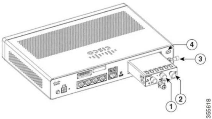
InstallanLTEPluggableModuleonaC1101-4P
To insert the LTE pluggable module into the router, do these steps:
Step 1 Insert and then gently push the LTE pluggable into the pluggable slot of C1101-4P until firmly fixed.
Step2 Tighten the screw, the recommended torque is 10-12 in-lb.
Figure54:LTEPluggable-C1101-4P
text_image
355618| DescriptionItem | |
| GPS Antenna1 | |
| LTE Antenna2 | |
| Ground Lug3 | |
| Kensington Lock Slot4 |
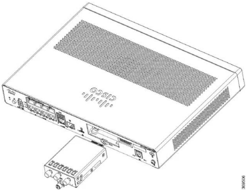
Figure55:LTEPluggable-C1127X-8PLTEP
natural_image
Line drawing of a network switch device with ports and ventilation grilles (no text or symbols)| DescriptionItem | |
| GPS Antenna1 | |
| LTE Antenna2 | |
| Ground Lug3 | |
| Kensington Lock Slot4 |
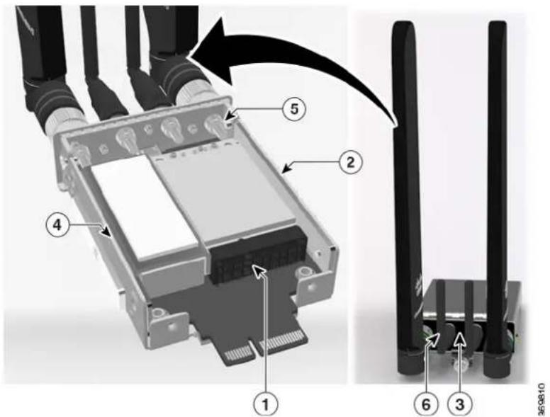
Figure56:LTEPluggable-C1118-8PLTEAP
text_image
Technical diagram of a wireless device showing labeled components including a connector, cable, and network ports.| DescriptionItem | |
| Mini-PCIE1 | |
| Common heat spreader + thermal interface2 | |
| 3 | I/O |
| Enclosure base to support 4-antenna4 | |
| 4-1 SMA-MHF4 cable assembly5 | |
| SMA Diversity Antenna for usability and Micro-USB port access6 |
Figure57:LTEPluggable-C1118-8PLTEAPBackPanel
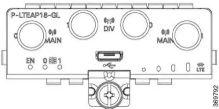
text_image
P-LTEAP18-GL MAIN DIV MAIN EN 0 1 LTE 369792Figure58:C1118-8PLTEAPwithMicroSIMSlots
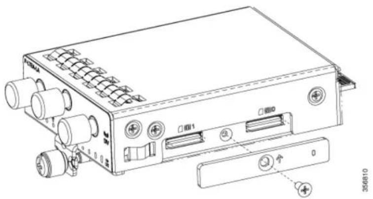
text_image
FATEA FATE1 FATE0 ↑ 0 356810This section describes how to insert a Micro-SIM card into an LTE pluggable module.
To insert the Micro-SIM cards into an LTE Pluggable module:

Note
Ensure to use the correct tool for removing the Micro-SIM door.
- Place the pluggable module on its bottom side, remove the SIM door screw, use a #1 Philips screw driver for removing the screws, and then carefully remove the Micro-SIM cover from the pluggable module.

Caution
Do not touch any part of the exposed PCB circuit area when the Micro-SIM cover is removed.
- In the figure, step 2 below shows the Micro-SIM slot 1 (label 1) and Micro-SIM slot 0 (label 2).
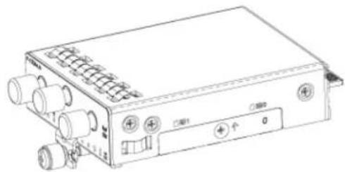
- Push in each Micro-SIM card (label 3) into the slot until it clicks. Secure the Micro-SIM cover with a screw, use a number 1 Philips screw driver to secure the screw on the Micro-SIM cover. The recommen torque is 2.8 - 3.8 inch LBF.
- You have now successfully inserted the Micro-SIM cards into the LTE pluggable module. The marking on the Mirco-SIM door should align with Micro-SIM0 on the pluggable module with the arrow pointing upward.
Figure59:InserttheMicro-SIMcards
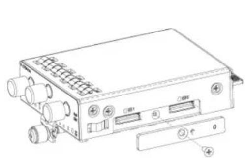
natural_image
Line drawing of a rectangular electronic device with ports and connectors (no text or symbols)STEP 1
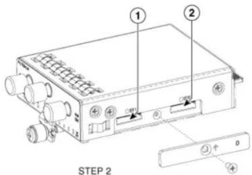
text_image
STEP 2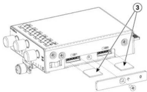
text_image
Technical diagram of an electronic device with labeled ports and buttons, showing internal components and a control panel.STEP 3
natural_image
Line drawing of an electronic device with ports and connectors (no text or symbols)STEP 4
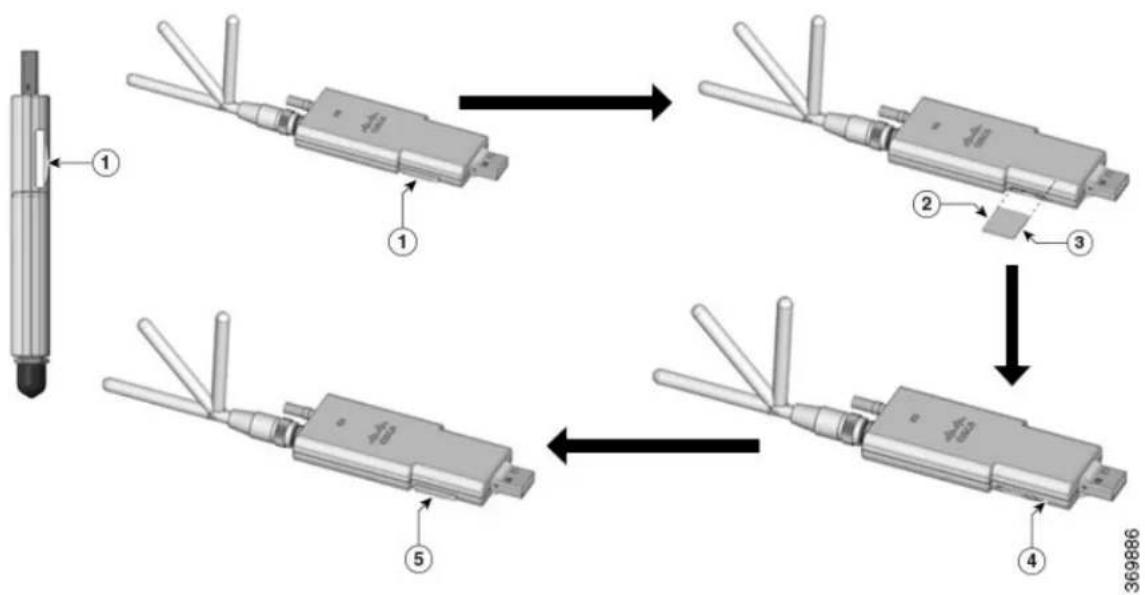
InstallaMicro-SIMCardintoaUSBLTEDongle
This section describes how to insert a micro-SIM card into a USB LTE dongle in a C1101-4P router.
Figure60: Micro-SIMCardSlotwithDustCover
flowchart
graph TD
    A["Sensor Input"] --> B["1"]
    B --> C["2"]
    C --> D["3"]
    D --> E["4"]
    E --> F["5"]
    F --> G["6"]
    style A fill:#f9f,stroke:#333
    style B fill:#ccf,stroke:#333
    style C fill:#cfc,stroke:#333
    style D fill:#fcc,stroke:#333
    style E fill:#cff,stroke:#333
    style F fill:#ffc,stroke:#333
    style G fill:#cfc,stroke:#333
Step1To insert a micro-SIM card into a USB LTE dongle, do these steps:
a. Tap open the micro-SIM protective cap on the USB dongle, gently insert the micro-SIM card with its edge oriented as shown in the figure until the SIM is seated in the socket.
b.Tap close the micro-SIM protective cap on the USB to close the slot.
Step2To remove a micro-SIM card into a USB LTE dongle, do these steps:
a. Tap open the dust cover, and then gently push the micro-SIM card to eject the card from the SIM slot.
b.Tap close the micro-SIM protective cap on the USB to close the slot.

Note
The antenna orientation may need to be adjusted for optimal performance.
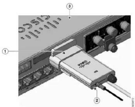
Perform the following steps to insert the USB LTE dongle with the SIM card into a horizontal slot on the panel of a C110x series router:
-
Ensure the micro-SIM is installed in the LTE USB dongle.
-
Plug the LTE USB dongle into the magnet holder.
-
Attach the magnet holder into the USB port on the metal front panel of C1101-4P.
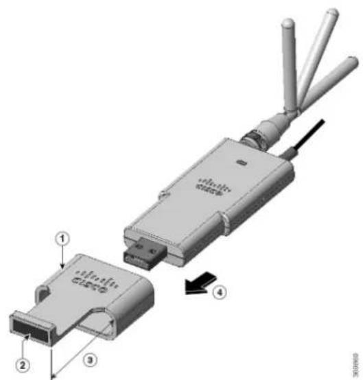
Figure61: LTEUSB2.0DongleforC1101-4P
text_image
Technical diagram of a device with numbered components and labeled parts, likely for assembly or manufacturing documentation.| DescriptionNumber | |
| Supporting ring1 | |
| Magnct2 | |
| Extend outward 30mm3 | |
| Plug-in direction4 |
text_image
Diagram of an electronic device showing labeled components including a USB drive and ports, with numbered annotations.| DescriptionNumber | |
| Supporting ring1 | |
| Donglc holder with magnet2 | |
| Router-C1101-4PLTEPW3 |
Follow the same procedure to install the USB LTE dongle onto routers with a vertical USB slot.
AntennaMountingInstructions
This section describes how to mount the antenna on Cisco 1000 Series ISRs. The information is contained in the following sections:
RackMountoftheAntenna
To install the antenna on a rack, do these steps:
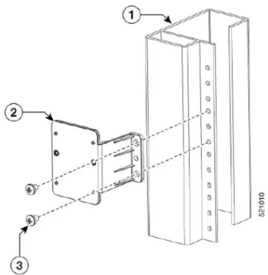
OptionA-RackMountataDifferentHeightwiththePlatform
Step1Pick up the R-Brackets (700-121611-01)
Step2Place and fix the bracket at an appropriate location on the rack using two screws.
Step3 Tighten the screw, the recommended torque is 10-12 in-lb.
text_image
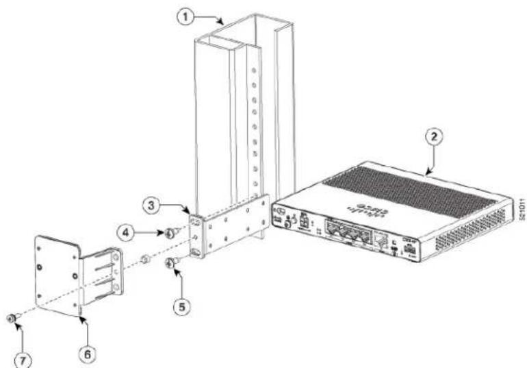
Technical diagram showing assembly steps of a mechanical component with numbered parts and dimension label 52/1010OptionA-RackMountattheSameHeightwiththePlatform
Step 1 Pick up the R-Brackets (700-121611-01) Place and fix the bracket at an appropriate location on the rack using two screws.
Step2 Tighten the screw, the recommended torque is 10-12 in-lb.
text_image
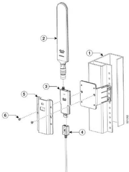
Diagram of an electronic device showing labeled components including a switch, ports, and a server unit with port 52-1011.Both options - A and B should follow these remaining steps to complete the mounting procedure:
- Assemble dongle, USB, cable and antenna together in advance.
- Pick up the wall-mounting bracket (700-121609-01) and 2 SCREWS (48-0580-01).
- Align and fasten the screws.
- Plug the USB cable to the USB port on the chassis to complete the mounting procedure.
text_image
Technical diagram of a mechanical device assembly with numbered components and labeled parts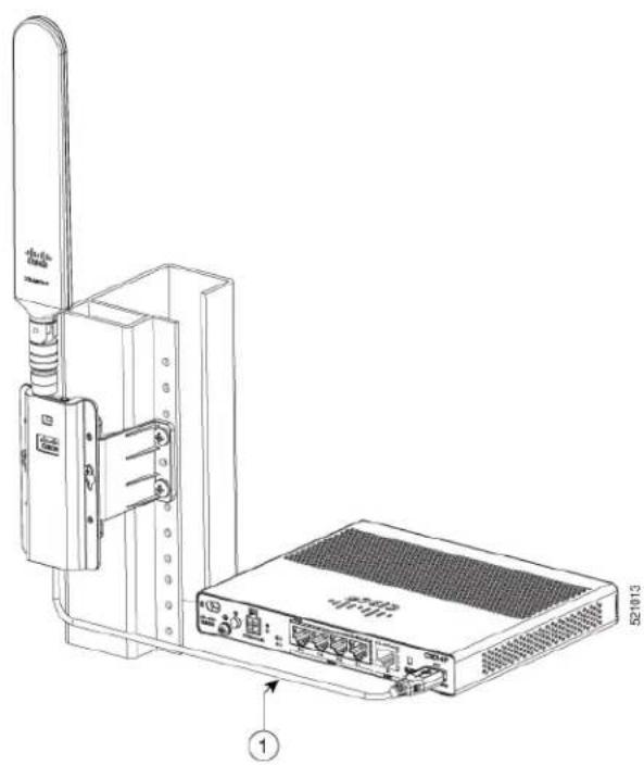
natural_image
Technical line drawing of a wireless device with an Ethernet port and network equipment (no text or symbols)WallMountoftheAntenna
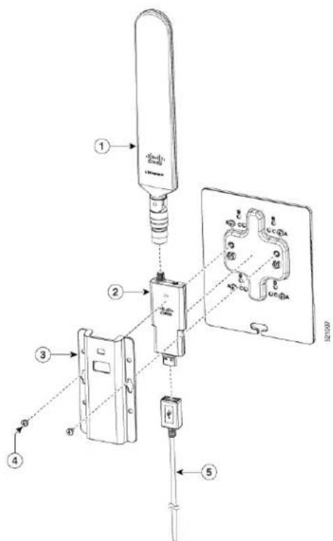
To install the antenna on a wall, do these steps:
Step 1 Pick up the C-Bracket (700-121628-01), place the bracket and then fix it on the wall using four screws.
Step 2 Assemble the USB cable (74-122795-01), dongle and antenna (07-100470-01) together. Pick up the wall-mount bracket (700-121609-01), two SCREWS (48-0580-01). Align and fasten the screws (recommended torque is 10-12 in-lb), the wall-mount is complete.
text_image
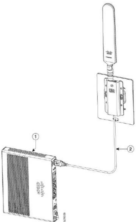
Technical diagram of a device assembly with numbered components and labeled partsConnecttheAntennatotheDevice
Step1 Ensure the reserved USB cable length is sufficient to reach the device.
Step 2 Ensure the use the cable clip within USB cable kit (74-122795-01) to manage cable routing and to hold the cable weight.
Step3 Ensure there are no sharp radius within the USB cable routing.
text_image
Diagram showing a device connection with labeled parts including a 1-chip connector and a battery pack, connected by wires.CeilingMountoftheAntenna
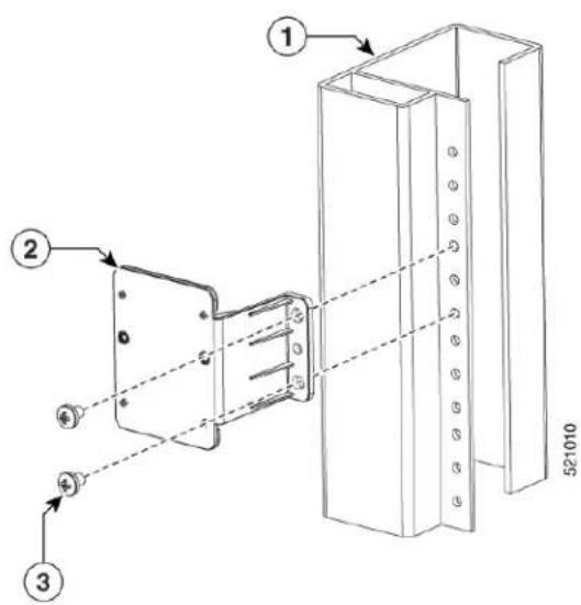
To install the antenna on a rack, do these steps:
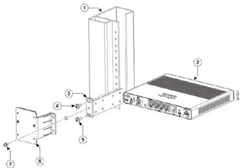
OptionA-RackMountataDifferentHeightwiththePlatform
Step1Pick up the R-Brackets (700-121611-01)
Step2Place and fix the bracket at an appropriate location on the rack using two screws.
Step3 Tighten the screw, the recommended torque is 10-12 in-lb.
text_image
① ② ③ 521010OptionA-RackMountattheSameHeightwiththePlatform
Step 1 Pick up the R-Brackets (700-121611-01) Place and fix the bracket at an appropriate location on the rack using two screws. Step2 Tighten the screw, the recommended torque is 10-12 in-lb.
text_image
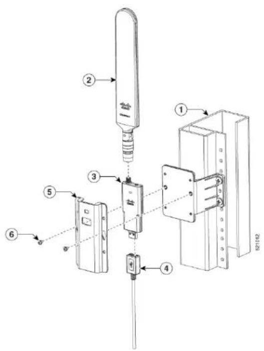
Diagram of an electronic device showing labeled components including a switch, ports, and a rack unit.Both options - A and B should follow these remaining steps to complete the mounting procedure:
-
Assemble donglc, USB, cable and antenna together in advance.
-
Pick up the wall-mounting bracket (700-121609-01) and 2 SCREWS (48-0580-01).
-
Align and fasten the screws.
-
Plug the USB cable to the USB port on the chassis to complete the mounting procedure.
text_image
Technical diagram of a mechanical assembly with numbered components, likely for industrial or laboratory testing.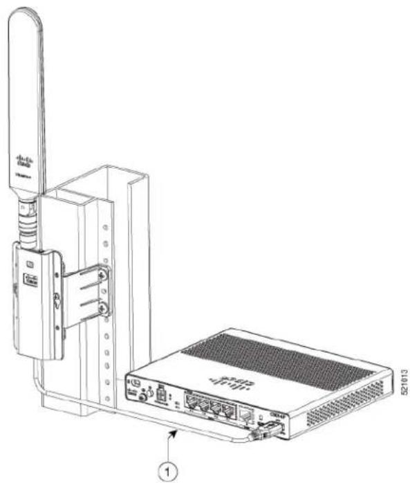
natural_image
Technical line drawing of a wireless device with an attached network switch and ports (no text or symbols)
natural_image
City skyline with modern skyscrapers under bright sunlight, foreground shows rooftop solar panels (no visible text or symbols)CHAPTER 5
ROMMonitorOverview
The ROMMON is the bootloader that initializes the hardware when the platform is powered on or reset. the ROMMON prompt, a Cisco IOS XE image can be manually booted. There is also an autoboot option boot a specified IOS XE image for every power-on or reset. When new features or significant defects are resolved, a newer ROMMON release is available on CCO. To determine the current ROMMON version; the location of the latest ROMMON release, these details are available in the following sections:
• ROM Monitor Overview, on page 79
ROMMonitorOverview
The ROM Monitor software is also known as ROMMON, boot software, boot image, or boot helper. Although it is distributed with routers that use the Cisco IOS XE software, the ROMMON is a separate program the Cisco IOS XE software. During normal startup, ROMMON initializes the router, and then, the contro passes to the Cisco IOS XE software.
When you connect a terminal to the router that is in ROMMON mode, the ROMMON command-line int (CLI) prompt is displayed.
Access the ROMMON mode to perform these tasks:
- Specify config-register value to use for the next boot up
- Boot a valid IOS XE image
- Bypass NVRAM settings and config-register value for password recovery

Note
After the Cisco IOS XE software boots up, ROMMON is no longer in use.
EnvironmentalVariablesandtheConfigurationRegister
Two primary connections exist between ROMMON and the Cisco IOS XE software: the ROMMON environment variables and the configuration register.
The ROMMON environment variables define the location of the Cisco IOS XE software and describe how to load it. After ROMMON has initialized the router, it uses the environment variables to locate and load t Cisco IOS XE software.
The configuration register is a software setting that controls how a router starts up. One of the primary uses of the configuration register setting is to control whether the router starts in ROMMON mode or Administration EXEC mode. The configuration register is set in either ROMMON mode or Administration EXEC mode as needed. You can set the configuration register using the Cisco IOS XE software prompt when you need to use ROMMON mode. When maintenance in ROMMODE mode is complete, change the configuration register back so that the router reboots with the Cisco IOS XE software.
AccessROMMONModewithaTerminalConnection
When the router is in ROMMODE mode, you can access the ROMMODE software only from a terminal connected directly to the console port of the card. Because the Cisco IOS XE software (EXEC mode) is in operation, the nonmanagement interfaces are not accessible. Therefore, all Cisco IOS XE software resources are unavailable.
NetworkManagementAccessandROMMONMode
ROMMON mode is a router mode, not a mode within the Cisco IOS XE software. The ROMMON softwar and the Cisco IOS XE software are two separate programs that run on the same router. At any given time, router is running one of these programs, but it never runs both at the same time.
One area that can be confusing when using ROMMON and the Cisco IOS XE software is the area that defines the IP configuration for the Management Ethernet interface. Most users are comfortable with configuring the Management Ethernet interface in the Cisco IOS XE software. When the router is in ROMMON mode, however, the router is not running the Cisco IOS XE software, therefore, Management Ethernet interface configuration is not available.
When you want to access other devices, such as a TFTP server, while in ROMMON mode on the router, must configure the ROMMON variables with IP access information.
For more information on ROMMON and Basic Procedures, refer to the Upgrading Field-Programmable Hardware Devices for Cisco 1000 Series ISRs

text_image
CHAPTER 6SupplierDeclarationofConformity
This equipment has been tested and found to comply with the limits for a Class A digital device, pursu: Part 15 of the FCC Rules. These limits are designed to provide reasonable protection against any harmful interference when the equipment is operated in a commercial environment. This equipment generates, uses and can radiate radio frequency energy, and if it is not installed and used in accordance with the instruct manual, it may may cause harmful interference to radio communications.
• This device may not cause harmful interference.
- This device must accept any interference received, including interference that may cause an undesire operation.
The operation of this equipment in a residential area is likely to cause harmful interference, in which ca users are required to correct the interference at their own expense.
RadioCompliance
This system uses both licensed and licensed exempt radio frequencies. The radios are evaluated to the follo regulations:
The Wi-Fi Radio is evaluated to 47 Code of Federal Regulations Part 15.247 and Part 15.407.
Part 15 Radio Systems operating outdoors in the 5150-5250 MHz band must comply with the antenna installation requirements as set forth in the FCC Part 15.407 rules.
The LTE radio is evaluated to 47 Code of Federal Regulation Part 24 and 27.
The LTE radio operates on licensed frequency bands and requires a radio license to operate. It must be under the control of a Licensed Service Provider or Wireless Carrier.
ModificationsbyUserorInstaller
Modifying the equipment without Cisco's authorization may result in the equipment being no longer compl with FCC requirements for Class A digital devices. In that event, your right to use the equipment may I limited by FCC regulations, and you may be required to correct any interference to radio or television communications at your own expense.
Changes or modifications not expressly approved by the party responsible for compliance could void the user's authority to operate the equipment.
FCCRFExposureCompliance
This product has been found to be compliant to the requirements set forth in CFR 47 Section 1.1307 add RF Exposure from radio frequency devices, as defined in Evaluating Compliance with FCC Guidelines for Human Exposure to Radio Frequency Electromagnetic Fields.
To maintain compliance, the minimum separation distance from the antenna to general bystander is 20 cm (8.7 inches) or more.
CANADA
This Class [*] digital apparatus complices with Canadian ICES-003.
This product complies with RSS-247 of the Industry Canada Rules. Its operation is subject to the following two conditions:
- This device may not cause harmful interference.
- This device must accept any interference received, including interference that may cause an undesired operation.
The device for operation in the band 5150-5250 MHz is only for indoor use to reduce the potential for hair interference to co-channel mobile satellite system.
For devices with detachable antenna(s), the maximum antenna gain permitted for devices in the bands 5250-535 MHz and 5470-5725 MHz must be such that the equipment still complies with the e.i.r.p. limit.
For devices with detachable antenna(s), the maximum antenna gain permitted for devices in the band 5725-585 MHz must be such that the equipment still complies with the e.i.r.p. limits as appropriate.
For systems that are capable of operating outdoors or with antennas mounted outdoors (where applicable antenna type(s), antenna models(s), and worst-case tilt angle(s)) are necessary to remain compliant with the e.i.r.p, therefore, the elevation mask requirement set forth in section 6.2.2.3 should be clearly indicated.
Radio(WiFi)
This product complies with the RSS of the Industry Canada rules.
RadiationExposureStatement
This equipment complies with IC radiation exposure limits set forth for an uncontrolled environment. This equipment should be installed and operated with a minimum distance of 20 cm (7.87 in.) between the radia and yourself.

Note
C1109-4PLTE2P = 27 cm
This telecommunication equipment conforms to NTC/NBTC technical requirement (optional)
Radiocommunication equipment has electromagnetic field strength in compliance with the Safety Standard for the Use of Radiocommunication Equipment on Human Health announced by the National Telecommunication Commission.