
C1116-4PWE - Router CISCO - Free user manual and instructions
Find the device manual for free C1116-4PWE CISCO in PDF.


User questions about C1116-4PWE CISCO
0 question about this device. Answer the ones you know or ask your own.
Ask a new question about this device
Download the instructions for your Router in PDF format for free! Find your manual C1116-4PWE - CISCO and take your electronic device back in hand. On this page are published all the documents necessary for the use of your device. C1116-4PWE by CISCO.
USER MANUAL C1116-4PWE CISCO
natural_image
Rooftop solar panel array in front of a modern city skyline at sunset (no text or symbols visible)Hardware Installation Guide for the Cisco 1100 Series Integrated Services Router
Last Modified: 2018-04-04
Americas Headquarters
Cisco Systems, Inc.
170 West Tasman Drive
San Jose, CA 95134-1706
USA
http://www.cisco.com
Tel: 408 526-4000
800 553-NETS (6387)
Fax: 408 527-0883
© 2017-2017 Cisco Systems, Inc. All rights reserved.

natural_image
City skyline with modern skyscrapers under a bright sky, no visible text or signageCONTENTS
Preface
Preface vii
Audience vii
Document Organization vii
Document Conventions viii
Related Documentation ix
Obtaining Documentation and Submitting a Service Request x
CHAPTER 1
Overview of Cisco 1000 Series Integrated Services Routers 1
Overview 1
About Cisco 1100 Series Integrated Service Routers 1
Chassis Views 2
Labels on the Router 3
For Additional Help Locating Labels on the Router 4
Hardware Features 4
Interface Ports 4
Power-over-Ethernet (PoE) 5
LED Indicators 5
Reset Button 10
Slots and Interfaces 10
About Slots, Subslots, and Port Numbering 10
Subslot/Bay Numbering 11
Specification 11
Periodic Inspection and Cleaning 14
CHAPTER 2
Preparing for Router Installation 15
Preparing for Router Installation 15
Safety Recommendations 15
Safety With Electricity 15
Preventing Electrostatic Discharge Damage 16
General Site Requirements 16
Site Selection Guidelines 17
Rack Requirements 17
Router Environmental Requirements 17
Power Guidelines and Requirements 18
Network Cabling Specifications 18
Console Port Connections 19
EIA/TIA-232 19
USB Serial Console 19
Console Port Considerations 20
Preparing for Network Connections 20
Ethernet Connections 20
Required Tools and Equipment for Installation and Maintenance 20
Installation Checklist 21
Creating a Site Log 22
CHAPTER 3
Installing and Connecting the Router 23
Installing and Connecting the Router 23
Safety Warnings 23
What You Need to Know 23
Before You Begin 24
Unpacking the Router 24
Installing the Router 24
Installing a Cisco 1100 Series ISR 24
Attaching the Chassis 25
Mounting on the Wall 25
Attaching DIN Rail Brackets 28
Mounting the Router in a Rack 30
Setting the Chassis on a Desktop 31
Chassis Grounding 31
Connecting to a Console Terminal or Modem 32
Connecting to the Serial Port with Microsoft Windows 33
Connecting to the Console Port with Mac OS X 34
Connecting to the Console Port with Linux 34
Installing the Cisco Microsoft Windows USB Device Driver 35
Installing the Cisco Microsoft Windows XP USB Driver 35
Installing the Cisco Microsoft Windows 2000 USB Driver 36
Installing the Cisco Microsoft Windows Vista USB Driver 36
Installing the Cisco Microsoft Windows 8/Windows 10 USB Driver 36
Uninstalling the Cisco Microsoft Windows USB Driver 37
Uninstalling the Cisco Microsoft Windows XP and 2000 USB Driver 37
Uninstalling the Cisco Microsoft Windows Vista USB Driver 38
Connecting WAN and LAN Interfaces 38
Ports and Cabling 39
Connection Procedures and Precautions 39
CHAPTER 4
ROM Monitor Overview and Basic Procedures 41
ROM Monitor Overview and Basic Procedures 41
ROM Monitor Overview 41
Entering ROM Monitor Mode 42
Checking the Current ROMmon Version 42
Commonly Used ROM Monitor Commands 43
Displaying the Available ROM Monitor Commands 43
Examples 44
Changing the ROM Monitor Prompt 44
Displaying the Configuration Register Setting 44
Environment Variable Settings 45
Frequently Used Environmental Variables 45
Displaying Environment Variable Settings 45
Entering Environment Variable Settings 46
Saving Environment Variable Settings 46
Exiting ROM Monitor Mode 46
Configuration Example 47
Upgrading the ROMmon for a Router 47
CHAPTER 5
Installing and Upgrading Internal Modules and FRUs 49
Installing and Upgrading Internal Modules and FRUs 49
Safety Warnings 49
Accessing Internal Modules 49
Replacing the Chassis Cover 50
Removing the Cover 50
Replacing the Cover 51
Locating Internal and External Slots for Modules 51
Installing the Internal PoE Daughter Card 52
Removing and Replacing the Internal PoE Daughter Card 53
Removing and Replacing the USB Flash Token Memory Stick 53
AC Power Supplies 54
Overview of the AC Power Supply 54
Installing and Removing SFP Modules 54
Installing SFPs 61
Removing SFP Modules 61
CHAPTER 6
Declaration of Conformity for RF Exposure 63
Declaration of Conformity of RF Exposure 63

natural_image
City skyline with modern high-rise buildings and waterfront, bathed in warm sunlight (no visible text or signage)Preface
• Audience, page vii
• Document Organization, page vii
• Document Conventions, page viii
• Related Documentation, page ix
- Obtaining Documentation and Submitting a Service Request, page x
Audience
This guide is intended for Cisco equipment providers and service personnel who are technically knowledgeable and familiar with Cisco routers and Cisco IOS software and features. They would understand how to install, configure, and maintain the router, and they should be familiar with electronic circuitry and wiring practices, and have experience as an electronic or electromechanical technician. This guide identifies certain procedures that should be performed only by trained and qualified personnel.
Document Organization
| DescriptionTitleChapter//Appendix | ||
| Chapter 4 | ROM Monitor Overview and Basic Procedures | Provides an overview of ROM Monitor concepts and operations. |
| Chapter 5 | Installing and Upgrades Internal Modules and FRUs | Describes how to install and upgrade internal modules and field replaceable unit on the router. |
^1 Field Replaceable Unit
Document Conventions
This document uses the following conventions:
| DescriptionConvention | |
| ^ or Ctrl | Both the ^ symbol and Ctrl represent the Control (Ctrl) key on a keyboard. For example, the key combination ^D or Ctrl-D means that you hold down the Control key while you press the D key. (Keys are indicated in capital letters but are not case sensitive.) |
| bold font | Commands and keywords and user-entered text appear in bold font. |
| Italic font | Document titles, new or emphasized terms, and arguments for which you supply values are in italic font. |
| Courier font | Terminal sessions and information the system displays appear in courier font. |
| Bold Courier font | Bold Courier font indicates text that the user must enter. |
| Elements in square brackets are optional.[x] | |
| ... | An ellipsis (three consecutive nonbolded periods without spaces) after a syntax element indicates that the element can be repeated. |
| | | A vertical line, called a pipe, indicates a choice within a set of keywords or arguments. |
| [x | y] | Optional alternative keywords are grouped in brackets and separated by vertical bars. |
| {x | y} | Required alternative keywords are grouped in braces and separated by vertical bars. |
| [x {y | z}] | Nested set of square brackets or braces indicate optional or required choices within optional or required elements. Braces and a vertical bar within square brackets indicate a required choice within an optional element. |
| string | A nonquoted set of characters. Do not use quotation marks around the string or the string will include the quotation marks. |
| Nonprinting characters such as passwords are in angle brackets.< > | |
| Default responses to system prompts are in square brackets.[ ] | |
| !, # | An exclamation point (!) or a pound sign (#) at the beginning of a line of code indicates a comment line. |
Reader Alert Conventions
This document uses the following conventions for reader alerts:

Note
Means reader take note. Notes contain helpful suggestions or references to material not covered in the manual.

Tip
Means the following information will help you solve a problem.

Caution
Means reader be careful. In this situation, you might do something that could result in equipment damage or loss of data.

Timesaver
Means the described action saves time. You can save time by performing the action described in the paragraph.

Warning
Means reader be warned. In this situation, you might perform an action that could result in bodily injury.
Related Documentation
For related release documentation, see the following URLs:
Cisco 1100 Series ISR Release Notes: https://www.cisco.com/c/en/us/td/docs/routers/access/1100/release/16-6-2/isr1k-rel-notes-xe-16-6.html
Cisco 1100 Series ISR Configuration Guide - https://www.cisco.com/c/en/us/td/docs/routers/access/1100/software/configuration/guide/cisco_1100_series_swcfg.html
Obtaining Documentation and Submitting a Service Request
For information on obtaining documentation, submitting a service request, and gathering additional information, see What's New in Cisco Product Documentation at: http://www.cisco.com/cn/US/docs/general/whatsnew/whatsnew.html.
Subscribe to What's New in Cisco Product Documentation, which lists all new and revised Cisco technical documentation, as an RSS feed and deliver content directly to your desktop using a reader application. The RSS feeds are a free service.

text_image
CHAPTER 1Overview of Cisco 1000 Series Integrated Services Routers
• Overview, page 1
Overview
Cisco 1000 Series Integrated Services Routers (ISRs) with Cisco IOS XE Software combine Internet access, comprehensive security, and wireless services (LTE Advanced 3.0, Wireless WAN and Wireless LAN), are high-performance devices that are easy to deploy and manage. The routers are well suited for deployment as customer premises equipment (CPE) in enterprise branch offices, and in service provider managed service environments.
The Cisco 1000 ISRs provide enterprise grade-wired line-like functionality, such as quality of service (QoS) for cellular, Multi-VRF, advanced VPN, and unified communications solutions over LTE.
The 1000 Series also provides the ability to extend Cisco product-based networks to remote offices with a relatively low incremental investment, as well as to enable managed services offerings based on end-to-end Cisco system architecture.
4-port platforms are midrange performance, managed service provider platforms and enterprise platforms having:
• 4-port integrated front panel switch ports
• VDSL2 and ADSL2/2+ support
- Optional POE on LAN daughter card supporting 2PoE/1PoE+ ports
- Optional WLAN support - 802.11ac WAVE 2
• 4G LTE-Advanced support with carrier aggregation
Chassis Views
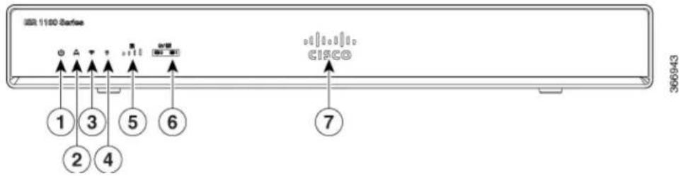
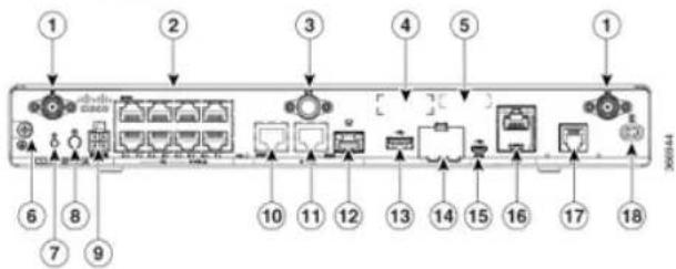
This section contains views of the front and back panels of the Cisco 1100 Series ISR, showing locations of the power and signal interfaces, interface slots, status indicators, and chassis identification labels.
Bezel View
Figure 1: Cisco 1100 Series ISR - Bezel View
text_image
IBM 1100 Series 1 3 5 6 2 4 Cisco 7 366943| VPN2Status1 | |||
| GPS4WiFi3 | |||
| LTE Data/SIM6LTE Sig | |||
| Illuminated Cisco Logo7 | |||
I/O View
Figure 2: Cisco 1100 Series ISR - I/O Views
text_image
1 2 3 4 5 1 6 7 8 9 10 11 12 13 14 15 16 17 18| 1 | LTE Antennas - Main and Diversity | 2 | LAN |
| 3 | GPS Connection | 4 | CLEI Label |
| 5 | Serial Number | 6 | Grounding |
| 7 | Reset Button | 8 | Power Switch |
| 9 | 4-pin Power Connector | 10 | GE 0/0/1 |
| 11 | GE 0/0/0 - RJ45 | 12 | GE 0/0/0 - SFP |
| 13 | USB3.0 | 14 | uSIM*2 |
| 15 | LTE Provisioning Port | 16 | RJ45 / Micro USB Console |
For Additional Help Locating Labels on the Router
Overview of Cisco 1000 Series Integrated Services Routers
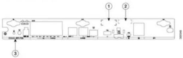
Figure shows the location of the labels on the Cisco 1100 Series ISRs:
Figure 3: Labels on the Routers
flowchart
graph TD
    A["Initial Setup"] --> B["Intermediate Processing"]
    B --> C["Final Output"]
    subgraph Step 1
        D["Start"] --> E["Process Unit"]
        F["End"] --> G["Output"]
    end
    subgraph Step 2
        H["Start"] --> I["Process Unit"]
        J["End"] --> K["Output"]
    end
| Sl. No | Name | Description |
| 1 | CLEI Number | Common Language Equipment Identifier (CLEI) number |
| 2 | Serial Number | |
| 3 | PID Family Name | Product Identification Number |
For Additional Help Locating Labels on the Router
Use the Cisco Product Identification (CPI) tool to find labels on the router. The tool provides detailed illustrations and descriptions of where the labels are located on Cisco products. It includes the following features:
- A search option that allows browsing for models by using a tree-structured product hierarchy
• A search field on the final results page that makes it easier to look up multiple products
The Cisco ISR C1100-4P series comes with 4-Gigabit Ethernet LAN ports, and two WAN ports, with or for one LTE modem and one WLAN interface.
Power-over-Ethernet (PoE)
The C1100-8P series has 8 Ethernet LAN ports. Four of the Ethernet LAN ports are PoE-capable, LAN 0-3. A total of 80W of PoE power is available across the four PoE-capable ports on the C1100-8P series. The C1100-4P series has 4 Ethernet LAN ports. Two of the Ethernet LAN ports are PoE-capable, LAN 0-1. A total of 60W of PoE power is available across the two PoE-capable ports on the C1100-4P series. Each individual PoE-capable Ethernet LAN port is capable of PoE 802.3af or PoE + 802.3at functionality. The total number of PoE and/or PoE + devices that can be enabled on the PoE ports at any one time is of the PoE power available from the external power supply. Software will allocate PoE power based on PoE power requested by the device on each port; and manage the total available power so as not to all more power than what is available.
LED Indicators
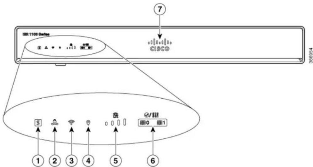
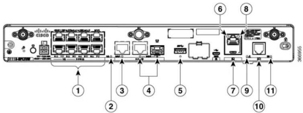
The following figures and table summarizes the LED indicators that are located in the router bezel or ch but not on the interface cards and modules.
Figure 4: LED Indicators - Bezel Side
text_image
DDR 1100 Server Cisco ⑦ 366954 ① ② ③ ④ ⑤ ⑥ #/柜 HHQ HH1| VPN2Status1 | |||
| GPS4WLAN3 | |||
| LTE DATA/SIM6LTE R | |||
| Cisco Logo7 |
Figure 5: LED Indicators - I/O Side
text_image
368055 ① ② ③ ④ ⑤ ⑥ ⑦ ⑧ ⑨ ⑩| 1 | (0,2,4,6 at the top and 1,3,5,7 at the bottom) | PoE LED2GE WAN Ports: 0-7 | |
| GE0 LED4GE1 LED3 | |||
| RJ-45 Console LED6USB LED5 | |||
| Micro USB Console LED8USB Co. | |||
| DSL10CD LED9 | |||
| DATA LED11 |
Table 1: LED Indicators - Description
| Port | LED Color | Description | Location |
| BlueCisco Logo | logo. Indicates router power is good. | Bezel sideBezel illuminated Cisco |
LocationDescriptionLED ColorPort
Green and AmberSTATUS
Bezel side. All models.Steady C
(System Status)
operates normally
Off—System is not out of reset; or BIOS image is not loadable.
Blinking Amber — BIOS/Rommon is booting.
Steady Amber — BIOS/Rommon has completed booting, and the system is at the Rommon prompt or booting the platform software.
GreenVPN OK
Off—No tunnel.
Bezel side
Steady On— at least one tunnel is up
Green and AmberLTE
RNSI/Mode On—No Service
Bezel Side
1 LED On— RSSI is under -100dBm
2 LEDs On— Low RSSI, -99dbm ◇ -90dBm
3 LEDs On— Medium RSSI -89dBm ◇ -70dBm
4 LEDs On— High RSSI,
-69dBm
Green— LTE
Amber— 3G
| LocationDescriptionLED ColorPort | |||
| Green and AmberGPS | Amber— Assisted GPS (Reserved for Future Use) | Bezel Side | |
| Green— Standalone GPS | |||
| Off— GPS not configured | |||
| On— GPS configured | |||
| Blink— GPS Acquiring | |||
| Green and AmberLTE DATA/SIM modem with SIM switch-over capability) | Bezcl SideSingle LTE Modem (one or | ||
| Green, Red, and Amber | WLAN— Normal operating condition with at least one wireless client association. | Bezcl side | |
| Red—Ethernet link is not operational or Ethernet failure. | |||
| Amber—Software upgrade is in progress. | |||
| Ports, Non-PoE | GreenEthernet Switch G | OffAN No link | I/O side |
| Steady On— link | |||
| Blink— TXD/RXD data | |||
| Port | LED Color | Description | Location |
| Ethernet Switch GE LAN Ports, with PoE | Green and Amber | Off— No link, no device powered, PD denied power, power delivery fault PoE administratively disabled. | I/O side |
| Green Steady On— link; if PoE device, power is enabled. | |||
| Green Blink— TXD/RXD data | |||
| Amber - PoE Fault | |||
| GE WAN Ports | Green | Off— No link | I/O side |
| Steady On— link | |||
| Blink— TXD/RXD data | |||
| DSL CD | Green | Off— Shut | I/O Side |
| Green Blink— Training, or no shut and cable disconnected. | |||
| Green Steady On— Trained | |||
| PoE OK | Green | Green Steady On— -53.5V PoE power supply connected and all | I/O Side |
Slots and Interfaces
Overview of Cisco 1000 Series Integrated Services Routers
| Port | LED Color | Description | Location |
| Console/AUX | Green and Amber | Green On— Console enabled. | I/O side |
| Amber On— AUX enabled. | |||
| USB Console | Green | Off— No USB device discovered. | I/O side |
| On— USB device discovered. | |||
| USB | Green | Off: No USB device discovered. | I/O Side |
| On: USB device discovered. |
Reset Button
The actuation of the Reset button is only recognized during Rommon boot, that is, as the router comes to the Rommon prompt.
The Reset button does not require much force to be actuated. The Reset button should be actuated only with a small implement such as the tip of a pen or a paper clip. When the Reset button is pressed at startup, the system LED will turn green.
For more information, see the "Reset Overview" section of the Cisco 1100 Series Software Configuration Guide.
Slots and Interfaces
Table 2: Slot, Bay, and Port Numbering
| PortBaySlot3- Tuple Example | |||
| 3rd2nd00/1/2 | |||
| 2nd1st00/0/1 |
Subslot/Bay Numbering
All interfaces are integrated interfaces. There is only one Bay, and the interface 'Type' is defined by a s number. In this example there is only one slot, 0, and each interface is a bay:
Bay 0 Ethernet WAN
Bay 1 Ethernet LAN (Switch)
Bay 2 LTE
Bay 3 DSL
Bay 4 WiFi
Chassis type: C1117-4PLTEEANE
Slot Type State Insert time (ago)
0 C1117-4PLTEEANE ok 00:05:58
0/0 C1117-1x1GE ok 00:03:03
0/1 C1117-ES-4 ok 00:03:01
0/2 C1117-LTE ok 00:02:52
0/3 C1117-VADSL-A ok 00:01:56
0/4 ISR-AP1100AC-E ok 00:03:13
Specification
The following table provide Cisco 1100 ISR specification:
Table 3: Cisco 1100 Series ISR Specification
| SpecificationDescription | |
| Physical Properties | |
| Dimensions (H x W x D) | Non-LTE models:H x W X D = 1.75 x 12.7 x 9.03 in. (42 x 323 x 230mm) (includes rubber feet) |
| LTE models:H x W X D = 1.75 x 12.7 x 9.6 in. (44 x 323 x 24 mm) (includes rubber feet) | |
| 5.5 Lbs. (2.5 kg) maximumWeight with AC PS (w/o m | |
| AC Input Power | |
| Universal 100 to 240 VACInput voltage | |
| 50-60 HzFrequency | |
| Input current | PoE not enabled: 0.82A maximumPoE enabled: 1.55A Maximum |
| 90 A peak and less than 8 Arms per half cycle Surge current | |
| Ports | |
| One RJ-45: Separate console portMicro USB Port | |
| USB port | USB 3.0 Type A host portUSB devices supported:• USB flash memory |
| Console port | One USB 5-pin micro Type B: Console management connectivity |
| 10/100/1000 Gigabit Ethernet | Two GE ports allocated among RJ45 and SFP as:One combo port with 10/100/1000RJ-45 Ethernet port or SFP Ethernet port (labeled GE0/0/0)One dedicated 10/100/1000RJ-45 Ethernet port (labeled GE0/0/1) |
| 32 (encrypted and non-encrypted VLANs)Wireless VLANs | |
| 2x2 .11ac Wave 2Wireless specifications | |
| 4GBDefault and maximum DRAM | |
| 4GBDefault and maximum flash | |
| Inline PoE | 4 ports for -8P PIDs, 2 ports for -4P PIDs802.3af-compliant PoE or 802.3at-compliant PoE+ |
| Not Applicable - Fanless designAcoustic for Cisco 1100 Sc | |
| Description | Specification |
| Approvals and compliance | Emission47 CFR Part 15CISPR 32 Edition 2EN 300 386 V1.6.1EN 55032:2012/ AC:2013EN 55032:2015EN61000-3-2 2014EN61000-3-3: 2013FCC §15.21ICES-003 ISSUE 6:2016KN 32: 2015V-2/2015.04V-3/2015.04TCVN 7189: 2009CNS13438: 2006IEC 60950-1EN 60950-1UL 60950-1CSA C22.2 No. 60950-1ImmunityCISPR24: 2010 + AI: 2015 |
| SpecificationDescription | |
| Operating humidity | 5 to 85% relative humidity |
| Operating temperature | 32 to 104°F (0 to 40°C) Sea Level;32 to 77°F (0°C to 25°C) at 10,000 ft1.5°C derating per 1000 ft |
| 0-6560 ft (0-2000 m)Altitude in China | |
| 0-10,000 ft (0-3050 m)Altitude in all other countries | |
| Transportation and Storage | |
| -40 to 158°F (-40 to 70°C)Nonoperating temperature | |
| 5 to 95% relative humidity (noncondensing)Nonoperating hu | |
| 0 to 15,000 ft (0 to 4570m)Nonoperating altitude | |
Periodic Inspection and Cleaning
Periodic inspection and cleaning of the external surface of the router is recommended to minimize the negati impact of environmental dust or debris. The frequency of inspection and cleaning is dependent upon the severity of the environmental conditions, but a minimum of every six months is recommended. Cleaning involves vacuuming of router air intake and exhaust vents.

Note
Sites with ambient temperatures consistently above 25^ C or 77^ F and with potentially high levels of dust or debris might require periodic preventative maintenance cleaning.

text_image
CHAPTER 2Preparing for Router Installation
• Preparing for Router Installation, page 15
Preparing for Router Installation
This document provides pre-installation information, such as recommendations and requirements that should be before installing your router. See the following sections to prepare for installation:
Safety Recommendations

This warning symbol means danger. You are in a situation that could cause bodily injury. Before you work on any equipment, be aware of the hazards involved with electrical circuitry and be familiar with standard practices for preventing accidents. Use the statement number provided at the end of each warning to locate its translation in the translated safety warnings that accompanied this device

Warning There is the danger of explosion if the battery is replaced incorrectly. Replace the battery only with the same or equivalent type recommended by the manufacturer. Dispose of used batteries according to the manufacturer's instructions. Statement 1015
Warning Only trained and qualified personnel should be allowed to install or replace this equipment Statement 1030
Warning Do not locate the antenna near overhead power lines or other electric light or power circuits, or where it can come into contact with such circuits. When installing the antenna, take extreme care not to come into contact with such circuits, as they may cause serious injury or death. For proper installation and grounding of the antenna, please refer to national and local codes (for example, U.S.:NFPA 70, National Electrical Code, Article 810, Canada:Canadian Electrical Code, Section 54). Statement 1052
Warning Do not use this product near water; for example, near a bath tub, wash bowl, kitchen sink or laundry tub, in a wet basement, or near a swimming pool. Statement 1035
Warning Installation of the equipment must comply with local and national electrical codes. Statement 1074
Preventing Electrostatic Discharge Damage
Electrostatic discharge (ESD) can damage equipment and impair electrical circuitry. It can occur if electronic printed circuit cards are improperly handled and can cause complete or intermittent failures. Always follow ESD prevention procedures when removing and replacing modules:
- Ensure that the router chassis is electrically connected to ground.
- Wear an ESD-preventive wrist strap, ensuring that it makes good skin contact. Connect the clip to an unpainted surface of the chassis frame to channel unwanted ESD voltages safely to ground. To guard against ESD damage and shocks, the wrist strap and cord must operate effectively.
- If no wrist strap is available, ground yourself by touching a metal part of the chassis.
Caution For the safety of your equipment, periodically check the resistance value of the anti-static strap. It should be between 1 and 10 megohms (Mohm).
General Site Requirements
This section describes the requirements your site must meet for safe installation and operation of your router. Ensure that the site is properly prepared before beginning installation. If you are experiencing shutdowns or
unusually high errors with your existing equipment, this section can also help you isolate the cause of failures and prevent future problems.

This product relies on the building's installation for short-circuit (overcurrent) protection. Ensure that the protective device is rated not greater than: 20A. Statement 1005

To prevent the system from overheating, do not operate it in an area that exceeds the maximum recommended ambient temperature of: 40 degrees C. Statement 1047
Site Selection Guidelines
The Cisco 1100 Series ISRs require specific environmental operating conditions. Temperature, humidity, altitude, and vibration can affect the performance and reliability of the router. The following sections provide specific information to help you plan for the proper operating environment.
The Cisco 1100 Series ISRs are designed to meet the industry EMC, safety, and environmental standards described in the Regulatory Compliance and Safety Information for the Cisco 1100 Series ISRs document.
Rack Requirements
Cisco 1100 Series ISRs require brackets for use with a 19-inch rack.
The following information can help you plan your equipment rack configuration:
- Allow clearance around the rack for maintenance.
- Allow at least one rack unit of vertical space between routers; more clearance is required when stacking multiple Cisco 1100 Series ISRs. Provide adequate heat removal mechanism to keep the surrounding air temperature well within the specified operating temperature condition.

Note
More spacing may be required depending on the installation environment.
cause malfunctions and shutdowns, and can make maintenance difficult. Plan for access to both front and rear panels of the router.
When planning your site layout and equipment locations, refer to the General Site Requirements, section. If you are currently experiencing shutdowns or an unusually high number of errors with your existing equipment, these precautions and recommendations may help you isolate the cause of failure and prevent future problems.
- Ensure that the room where your router operates has adequate air circulation. Electrical equipment generates heat. Without adequate air circulation, ambient air temperature may not cool equipment to acceptable operating temperatures.
• Always follow ESD-prevention procedures described in the Preventing Electrostatic Discharge Damage to avoid damage to equipment. Damage from static discharge can cause immediate or intermittent equipment failure. - Baffles can help to isolate exhaust air from intake air, which also helps to draw cooling air through the chassis. The best placement of the baffles depends on the airflow patterns in the rack, which can be found by experimenting with different configurations.
- When equipment installed in a rack (particularly in an enclosed rack) fails, try operating the equipment by itself, if possible. Power off other equipment in the rack (and in adjacent racks) to allow the router under test a maximum of cooling air and clean power.
Power Guidelines and Requirements
Check the power at your site to ensure that you are receiving "clean" power (free of spikes and noise). Install a power conditioner if necessary.
Power Guidelines and Requirements lists power requirements for the Cisco 1100 Series ISRs.
Table 5: Power Requirements for Cisco 1100 Series ISRs
| Power Source | Input Rated | Output Rated |
| 66W AC Power Adapter(PWR-66W-AC-V2) | 100-240V, 2A | 12 VDC, 5.5A |
Console Port Connections
The router has both EIA/TIA-232 asynchronous (RJ-45) and USB 5-pin micro Type B, 2.0 compliant ser console ports. The console ports do not have any hardware flow control. Shielded USB cables with prop terminated shields are recommended.
EIA/TIA-232
Depending on the cable and the adapter used, this port appears as a DTE or DCE device at the end of cable. Only one port can be used at the same time.
The default parameters for the console port are 9600 baud, 8 data bits, 1 stop bit, and no parity. The c port does not support hardware flow control. For detailed information about installing a console terminal, the Connecting to a Console Terminal or Modem section.
For cable and port pinouts, see the Cisco Modular Access Router Cable Specifications document located Cisco.com.
USB Serial Console
The USB serial console port connects directly to the USB connector of a PC using a USB Type A to micro USB Type-B cable. The USB Console supports full speed (12Mb/s) operation. The console port does not support hardware flow control.

Always use shielded USB cables with a properly terminated shield. Note
The default parameters for the console port are 9600 baud, 8 data bits, no parity, and 1 stop bit. For d information about installing a console terminal, see the Connecting to a Console Terminal or Modem sec on page 3-19.
For operation with a Microsoft Windows OS version older than Windows 7, the Cisco Windows USB C Driver must be installed on any PC connected to the console port. If the driver is not installed, prompts you through a simple installation process.
The Cisco Windows USB Console Driver allows plugging and unplugging the USB cable from the console port without affecting Windows HyperTerminal operations. No special drivers are needed for Mac OS X Linux.
Only one console port can be active at a time. When a cable is plugged into the USB console port, the port becomes inactive. Conversely, when the USB cable is removed from the USB port, the RJ-45 port be active.
Baud rates for the USB console port are 1200, 2400, 4800, 9600, 19200, 38400, 57600, and 115200 bps

Note
4-pin micro USB Type-B connectors are easily confused with 5-pin micro USB Type-B connectors. On the 5-pin micro USB Type-B is supported.
USB Console OS Compatibility
- Windows 10, Windows 8, Windows 7, Windows 2000, Window XP 32 bit, Windows Vista 32 bit
• Mac OS X version 10.5.4
• Redhat / Fedora Core 10 with kernel 2.6.27.5-117
• Ubuntu 8.10 with kernel 2.6.27-11
- Debian 5.0 with kernel 2.6
• Suse 11.1 with kernel 2.6.27.7-9
Console Port Considerations
The router includes an asynchronous serial console port. The console ports provide access to the router using a console terminal connected to the console port. This section discusses important cabling information to consider before connecting the router to a console terminal or modem.
Console terminals send data at speeds slower than modems do; therefore, the console port is ideally suited for use with console terminals.
Preparing for Network Connections
When setting up your router, consider distance limitations and potential electromagnetic interference (EMI) as defined by the applicable local and international regulations.
Network connection considerations are provided for:
See the following online document for more information about network connections and interfaces:
• Cisco Modular Access Router Cable Specifications
Ethernet Connections
The IEEE has established Ethernet as standard IEEE 802.3. The routers support the following Ethernet implementations:
- 1000BASE-T—1000 Mb/s full-duplex transmission over a Category 5 or better unshielded twisted-pair (UTP) cable. Supports the Ethernet maximum length of 328 feet (100 meters).
- 100BASE-T—100 Mb/s full-duplex transmission over a Category 5 or better unshielded twisted-pair (U730) with. Surveys the Ethernet maximum length of 328 feet (100 meters).
• To install or remove modules
* To remove the cover, if you are upgrading memory or other components
- Screws that fit your rack
- Wire crimper
- Wire for connecting the chassis to an earth ground:
- AWG 14 (2 mm 2 ) or larger wire for NEC-compliant chassis grounding
- For NEC-compliant grounding, an appropriate user-supplied ring terminal, with an inner diameter of 1/4 in. (5 to 7 mm)
Installation Checklist
The sample installation checklist lists items and procedures for installing a new router. Make a copy of this checklist and mark the entries when completed. Include a copy of the checklist for each router in your site log (described in the next section, Creating a Site Log).
Table 6: Checklist
| Task | Verified By | Date |
| Installation checklist copied | ||
| Background information placed in Site Log | ||
| Site power voltages verified | ||
| Installation site power check completed | ||
| Required tools available | ||
| Chassis components verified | ||
| Initial electrical connections established | ||
| ASCII terminal (for local configuration) or modem (for remote configuration) available | ||
| Signal distance limits verified | ||
| Startup sequence steps completed | ||
| Initial operation verified | ||
| Software image verified |
Creating a Site Log
The Site Log provides a record of all actions related to the router. Keep it in an accessible place near the chassis where anyone who performs tasks has access to it. Use the installation checklist to verify steps in the installation and maintenance of the router. Site Log entries might include the following information:
- Installation progress—Make a copy of the installation checklist and insert it into the site log. Make entries as each procedure is completed.
- Upgrade and maintenance procedures—Use the site log as a record of ongoing router maintenance and expansion history. A site log might include the following events:
*Removal or replacement of PoE daughter card
-Configuration changes

text_image
CHAPTER 3Installing and Connecting the Router
• Installing and Connecting the Router, page 23
Installing and Connecting the Router
This document describes how to install and connect the Cisco 1100 Series Integrated Services Routers (ISRs) to LAN and WAN networks. The following sections provide technical details.
Safety Warnings

Read the installation instructions before using, installing or connecting the system to the power source. Statement 1004
What You Need to Know
Software Licenses
To use all the features on the router, you must purchase a software package.
See the Licensing section of the Software Configuration Guide for the Cisco 1100 Series ISRs for more information.
Before You Begin
Before installing and connecting a Cisco Integrated Services Router, read the safety warnings and gather the following tools and equipment. For more information about the required tools and equipment.

Note
For more information on cable specifications, see the Cisco Modular Access Router Cable Specifications document on Cisco.com.
Unpacking the Router
Do not unpack the router until you are ready to install it. If the final installation site will not be ready for time, keep the chassis in its shipping container to prevent accidental damage. When you are ready to install the router, proceed with unpacking it.
The router, accessory kit, publications, and any optional equipment you ordered may be shipped in more than one container. When you unpack the containers, check the packing list to ensure that you received all of the items on the list.
Installing the Router
If you need to install PoE daughter card, you can install them before you install the router. Ideally, the PoE daughter card should be purchased pre-installed.
There are two methods of installing the router:

Caution
To prevent damage to the chassis, never attempt to lift or tilt the chassis by holding it by the plastic panel on the front. Always hold the chassis by the sides of the metal body.
Installing a Cisco 1100 Series ISR
This section describes how to install the Cisco 1100 Series ISR. These routers can be installed on a table 1 or other flat horizontal surface mounted on a wall or DIN rail.

Warning
Radiofrequency Exposure - To maintain compliance, installations should ensure a separation distance of at least 20 cm.

Note
More clearance is required when stacking multiple Cisco 1100 ISRs or having heat removal capability to maintain the surrounding air temperature to stay within the specified operating condition.
Attaching the Chassis
The tasks that you perform for attaching the router chassis to the wall or for mounting it in a rack are on the specific model of the Cisco 1100 Series Integrated Service Router.
The recommended clearance when horizontally mounted is 1.5 inches on both sides for clearance and 1.7 inches on top. I/O side clearance is needed as it is required to access the cable connections. Clearance is required on the backside (opposite side from I/O face) unless DIN rail mounting is required. Clearance is required to attach and mount the DIN rail bracket.
Mounting on the Wall
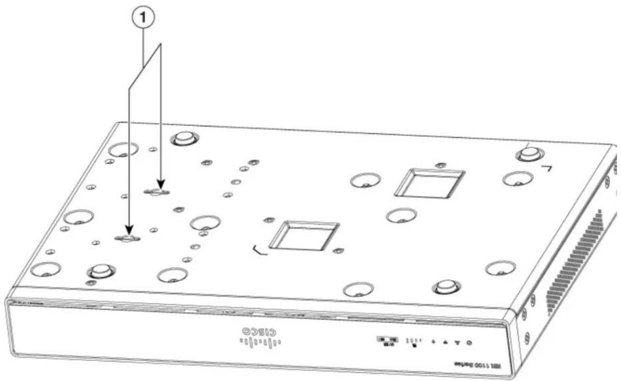
The Cisco 1100 Series ISRs have mounting key-hole slots on the bottom of the chassis for mounting the on a wall or other vertical surface, as shown in the figure below.

Note
The unit must not be mounted with the output ports facing downwards. You must mount the unit with the cables going sideways.
Figure 6: Mounting on the Wall
text_image
1 H2S6C H2S6C H2S6C H2S6C H2S6C H2S6C H2S6C H2S6C H2S6C H2S6C H2S6C H2S6C H2S6C H2S6C H2S6C H2S6C H2S6C H2N 10000000000000000000000000000000000000000000000000000000000000000000000000000000000000000000000000000| Key-hole slots1 |

Note
To attach to a wall stud, each bracket requires one number-10 wood screws (round- or pan-head) with number-10 washers, or two number-10 washer-head screws. The screws must be long enough to penetrate at least 1.5 inches (38.1 mm) into the supporting wood or metal wall stud.

Note
For hollow-wall mounting, each bracket requires two wall anchors with washers. Wall anchors and washers must be size number 10. Route the cables so that they do not put a strain on the connectors or mounting hardware.

Note
When choosing a location for wall-mounting the router, consider cable limitations and wall structure.
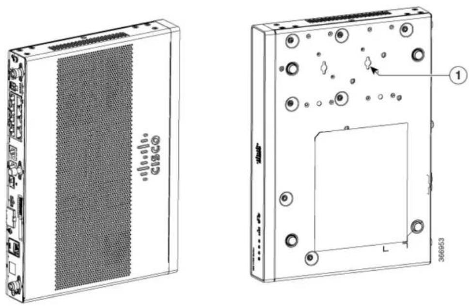
The figure below shows the orientation for wall mounting of the router.
Figure 7: Wall-Mount Orientation
natural_image
Technical line drawings of a server rack and its internal components, showing front and side views with no visible text or symbols.| Key-hole slots1 |
Attaching DIN Rail Brackets
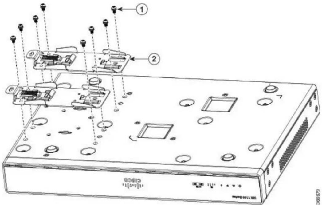
Step 1: Attach the brackets to the router chassis as shown in the figure below, using the PHMS screws and the plastic spacers provided for each bracket.
Figure 8: DIN Rail Bracket Installation
text_image
Technical diagram of a network device with labeled components and wiring connections| Screws1 | |
| DIN Rail Brackets2 |

Note
Do not over-torque the screws. The recommended torque is 8 to 10 inch-lbf (.9 to 1.1 N-m).

Your chassis installation must allow unrestricted airflow for chassis cooling. Note
Step 2: Attach the router to the wall using the key-hole slots.
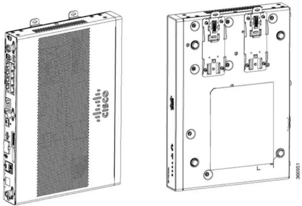
The figure below displays the orientation of the DIN rail bracket.
Figure 9: DIN Rail Bracket Orientation
natural_image
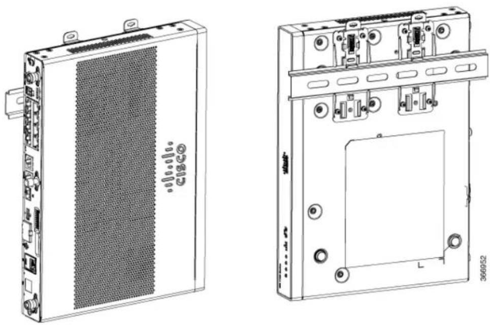
Technical line drawings of two electronic device modules, one with a CSCO port and the other showing internal components (no text or symbols)The figure below displays the DIN rail orientation and mount.
Figure 10: DIN Rail Orientation and Mount
natural_image
Technical line drawings of two electronic device modules, one with a mesh panel and the other with labeled ports and mounting holes (no text or symbols beyond labels)Installing the Router
Installing and Connecting the Router
After the router is installed, you must connect the chassis to a reliable earth ground. For the chassis ground connection procedures, see the "Chassis Grounding" section.
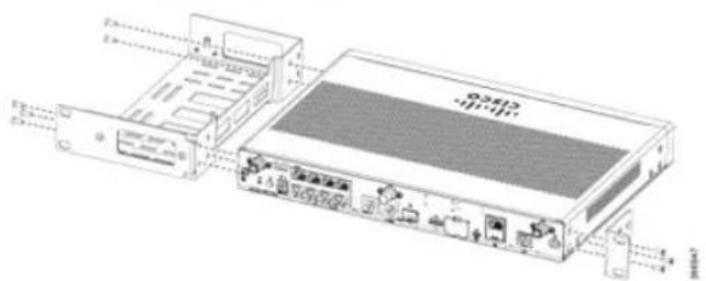
Mounting the Router in a Rack
1 Attach the brackets to the router chassis (towards the left or right) as shown in figure below.
Figure 11: Bracket Installation for Left-Hand-Mounting
text_image
Technical diagram of a network device showing ports, connectors, and I/O labels with Chinese annotations
Note
In the similar manner, you can install the bracket on the right-hand for mounting.
2 Use the screws provided with the rack to install the chassis in the rack.

Warning
To prevent bodily injury when mounting or servicing this unit in a rack, you must take special precautions to ensure that the system remains stable. The following guidelines are provided to ensure your safety:
- This unit should be mounted at the bottom of the rack if it is the only unit in the rack.
Setting the Chassis on a Desktop
You can place the router on a desktop, bench top, or shelf.
After the router is installed, you must connect the chassis to a reliable earth ground. For the chassis gro connection procedures, see the Chassis Grounding section.
Chassis Grounding

Warning
This equipment must be grounded. Never defeat the ground conductor or operate the equipment in the absence of a suitably installed ground conductor. Contact the appropriate electrical inspection authority or an electrician if you are uncertain that suitable grounding is available. Statement 1024
You must connect the chassis to a reliable earth ground; the ground wire must be installed in accordance with local electrical safety standards.
- For grounding, use size 14 AWG copper wire and the ground lug (which are not a part of the acc kit).
- Use the UNC 6-32 screws, which have a length of about 0.25 inches

Use 14AWG wire for installation.Note
To install the ground connection for your router, perform the following steps:
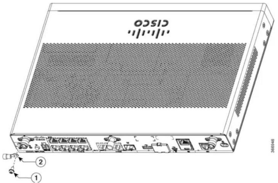
1 Strip one end of the ground wire to the length required for the ground lug or terminal.
• For the ground lug—approximately 0.75 inch (20 mm)
- For user-provided ring terminal—as required
2 Crimp the ground wire to the ground lug or ring terminal, using a crimp tool of the appropriate size
3 Attach the ground lug or ring terminal to the chassis as shown in Figure. For a ground lug, one of the screws provided. Tighten the screw to a torque of 8 to 10 in-lb (0.9 to 1.1 N-m).
Figure 12: Chassis Ground Connection on the Router
text_image
CISCO 360946| Screw (UNC 6-32)1 | |
| Ground Lug2 |
Connecting to a Console Terminal or Modem
The router has asynchronous serial ports. These ports provide administrative access to the router either local (with a console terminal or a PC) or remotely (with a modem). To configure the router through the Cisco 10 CLI, you must establish a connection between the router console port and either a terminal or a PC.
Use the following cables and adapters to establish a local or remote connection.
Table 7: Local and Remote Connections
| Port Type | Cable | Section | |
| Serial (RJ-45) | EIA RJ-45 | Connecting to the Serial Port with Microsoft Windows, on page 33 | |
| Serial (USB) | Micro USB Type-B to USB Type-A |
Connecting to the Serial Port with Microsoft Windows

Note
Install the USB device driver before establishing a physical connection between the router and the PC using the USB Console cable plugged into the USB serial port, otherwise the connection will fail. See the "Installing the Cisco Microsoft Windows USB Device Driver" section.
1 Connect the end of the console cable with the RJ-45 connector to the light blue console port on the router.
2 or
Connect a USB 5-pin micro USB Type-B to the USB console port. If you are using the USB serial port for the first time on a Windows-based PC, install the USB driver now according to the instructions in the following sections.
- "Installing the Cisco Microsoft Windows XP USB Driver" section
• "Installing the Cisco Microsoft Windows 2000 USB Driver" section - "Installing the Cisco Microsoft Windows Vista USB Driver" section
Connecting to a Console Terminal or Modem
Installing and Connecting the Router
• no parity
• I stop bit
- no flow control
Connecting to the Console Port with Mac OS X
This procedure describes how to connect a Mac OS X system USB port to the console using the built in OS X Terminal utility.
Step 1 Use the Finder to go to Applications > Utilities > Terminal.
Step 2 Connect the OS X USB port to the router.
Step 3 Enter the following commands to find the OS X USB port number
Example:
macbook:user$ cd /dev
macbook:user$ ls -ltr /dev/*usb*
crw-rw-rw- 1 root wheel 9, 66 Apr 1 16:46 tty.ubsmodunla21 DT-macbook:dev user$
Step 4 Connect to the USB port with the following command followed by the router USB port speed
Example:
macbook:user\$ screen /dev/tty.usbmodam121 9600 To disconnect the OS X USB console from the Terminal window Enter Ctrl-a followed by Ctrl-
Connecting to the Console Port with Linux
Example:
root@usb-suse /dev# screen /dev/ttyACM0 9600
To disconnect the Linux USB console from the Terminal window
Enter Ctrl-a followed by : then quit
Installing the Cisco Microsoft Windows USB Device Driver
A USB device driver must be installed the first time a Microsoft Windows-based PC is connected to the serial port on the router.
This section contains the following topics:
Installing the Cisco Microsoft Windows XP USB Driver
This procedure shows how to install the Microsoft Windows XP USB driver.
Before you begin, download the appropriate driver for your router model from the Cisco Software Downl site, USB Console Software category: http://www.cisco.com/cisco/software/navigator.html
Step 1 Unzip the file Cisco_usbconsole_driver_X_X.zip (where X is a revision number).
Step 2 If using 32-bit Windows XP double-click the file setup.exe from the Windows_32 folder, or if using 64-bit Windo XP double-click the file setup(x64).exe from the Windows_64 folder.
Step 3 The Cisco Virtual Com InstallShield Wizard begins. Click Next.
Step 4 The Ready to Install the Program window appears, Click Install.
Step 5 The InstallShield Wizard Completed window appears. Click Finish.
Step 6 Connect the USB cable to the PC and router USB console. The LED of the USB console port turns green, and few moments the Found New Hardware Wizard appears. Follow the instructions to complete the installation of the
Step 7 The USB console is now ready for use.
Installing the Cisco Microsoft Windows 2000 USB Driver
This procedure shows how to install the Microsoft Windows 2000 USB driver.
Step 1 Obtain the file Cisco_usbconsole_driver.zip from the Cisco.com web site and unzip it.
Step 2 Double-click the file setup.exe.
Step 3 The Cisco Virtual Com InstallShield Wizard begins. Click Next.
Step 4 The Ready to Install the Program window appears, Click Install.
Step 5 The InstallShield Wizard Completed window appears. Click Finish.
Step 6 Connect the USB cable to the PC and router USB console ports. The LED for the USB console port turns green, an within a few moments a series of Found New Hardware Wizard windows appear. Follow the instructions to complete the installation of the driver.
Step 7 The USB console is now ready for use.
Installing the Cisco Microsoft Windows Vista USB Driver
This procedure shows how to install the Microsoft Windows Vista USB driver.
Step 1 Obtain the file Cisco_usbconsole_driver.zip from the Cisco.com web site and unzip it.
Step 2 If using 32-bit Windows Vista double-click the file setup.exe from the Windows_32 folder, or if using 64-bit Window Vista double-click the file setup(x64).exe from the Windows_64 folder.
Step 3 The Cisco Virtual Com InstallShield Wizard begins. Click Next.
Step 4 The Ready to Install the Program window appears, Click Install. Note If a User Account Control warning appears, click "Allow - I trust this program..." to proceed.
Step 5 The InstallShield Wizard Completed window appears. Click Finish.
Step 6 Connect the USB cable to the PC and router USB console ports. The LED for the USB console port turns green, an within a few moments a pop up window stating "Installing device driver software" appears. Follow the instructions to complete the installation of the driver.
Step 7 The USB console is now ready for use.
Installing the Cisco Microsoft Windows 8/Windows 10 USB Driver
This procedure shows how to install the Microsoft Windows 8/Windows 10 USB driver.
Step 1 Obtain the Cisco USB console driver file from the Cisco.com web site and unzip it. Note You can download the driver file from the Cisco.com site for downloading the router software.
Step 2 If using 32-bit Windows 8 or Windows 10, double-click the setup.exe file in the Windows_32 folder. If using 64-Windows Vista or Windows 8 or Windows 10, double-click the setup(x64).exe file in the Windows_64 folder.
Step 3 The Cisco Virtual Com InstallShield Wizard begins. Click Next.
Step 4 The Ready to Install the Program window appears, Click Install. Note If a User Account Control warning appears, click Allow - I trust this program to proceed.
Step 5 The InstallShield Wizard Completed window appears. Click Finish.
Step 6 Connect the USB cable to the PC and router USB console ports. The LED for the USB console port turns green, within a few moments a series of Found New Hardware Wizard windows appear. Follow the instructions to compl the installation of the driver.
Step 7 The USB console is now ready for use.
Uninstalling the Cisco Microsoft Windows USB Driver
This section provides instructions for how to uninstall the Cisco Microsoft Windows USB device driver.
- Uninstalling the Cisco Microsoft Windows XP and 2000 USB Driver, on page 37
- Uninstalling the Cisco Microsoft Windows Vista USB Driver, on page 38
Uninstalling the Cisco Microsoft Windows XP and 2000 USB Driver
This procedure shows you how to uninstall both the Microsoft Windows XP and 2000 USB driver. The can be removed using the Windows Add Remove Programs utility or the setup.exe program.
Using the Add Remove Programs utility
Disconnect the router console terminal before uninstalling the driver.
1 Click Start > Control Panel > Add or Remove Programs.
2 Scroll to Cisco Virtual Com and click Remove.
3 When the Program Maintenance window appears, select the Remove radio button. Click Next.
Using the Setup.exe program

Disconnect the router console terminal before uninstalling the driver.Note
1 Run the setup.exe for Windows 32-bit or setup(x64).exe for Windows-64bit. Click Next.
2 The InstallShield Wizard for Cisco Virtual Com appears. Click Next.
3 When the Program Maintenance window appears, select the Remove radio button. Click Next.
4 When the Remove the Program window appears, click Remove.
5 When the InstallShield Wizard Completed window appears click Finish.
Connecting WAN and LAN interfaces
Installing and Connecting the Router
Uninstalling the Cisco Microsoft Windows Vista USB Driver
This procedure shows you how to uninstall the Microsoft Windows Vista USB driver.

Note
Disconnect the router console terminal before uninstalling the driver.
Step 1 Run the setup.exe for Windows 32-bit or setup(x6-1).exe for Windows-64bit. Click Next.
Step 2 The InstallShield Wizard for Cisco Virtual Com appears. Click Next.
Step 3 When the Program Maintenance window appears, select the Remove radio button. Click Next.
Step 4 When the Remove the Program window appears, click Remove.
Note If a User Account Control warning appears, click "Allow - I trust this program..." to proceed.
Step 5 When the InstallShield Wizard Completed window appears click Finish.
Connecting WAN and LAN Interfaces
This section describes how to connect WAN and LAN interface cables. It covers the following topics:

rning
Do not work on the system or connect or disconnect cables during periods of lightning activity. Statement 1001

rning
Class 1 laser product. Statement 1008

4
| Warning | Never install telephone jacks in wet locations unless the jack is specifically designed for wet locations. Statement 1036 |
| Warning | Never touch uninsulated telephone wires or terminals unless the telephone line has been disconnected at the network interface. Statement 1037 |
| Warning | For connections outside the building where the equipment is installed, the following ports must be connected through an approved network termination unit with integral circuit protection, LAN, PoE. Statement 1044 |
| Warning | Avoid using or servicing any equipment that has outdoor connections during an electrical storm. There may be a risk of electric shock from lightning. Statement 1088 |
Ports and Cabling
This chapter summarizes typical WAN and LAN connections for routers. The connections summarized here are also described in detail in the document on Cisco.com: Cisco Modular Access Router Cable Specifications
Table 8: WAN and LAN Connections
| Port or Connection | Port Type, Color ^2 | Connection: | Cable |
| Ethernet | RJ-45, yellow | Ethernet hub or Ethernet switch | Category 5 or higher Ethernet |
| Cisco serial | 60-pin D-sub, blue | CSU/DSU and serial network or equipment | Cisco serial transition cable that matches the signaling protocol (EIA/TIA-232, EIA/TIA-449, V.35, X.21, or EIA-530) and the serial port operating mode |
| Cisco Smart serial | Cisco Smart compact connector, blue | CSU/DSU and serial network or equipment |
Connecting WAN and LAN Interfaces
Installing and Connecting the Router
- Position the cables carefully, so that they do not put strain on the connectors.
- Organize cables in bundles so that cables do not intertwine.
- Inspect the cables to make sure that the routing and bend radius is satisfactory. Reposition cables, if necessary.
• Install cable ties in accordance with site requirements.
For cable pinouts, see Cisco Modular Access Router Cable Specifications.

text_image
CHAPTER 4ROM Monitor Overview and Basic Procedures
• ROM Monitor Overview and Basic Procedures, page 41
ROM Monitor Overview and Basic Procedures
This chapter provides an overview of ROM Monitor concepts and operations.
This chapter includes the following main topics:
ROM Monitor Overview
The ROM Monitor is a bootstrap program that initializes the hardware and boots the Cisco IOS XE software when you power on or reload a router. When you connect a terminal to the router that is in ROM Monitor mode, the ROM Monitor command-line interface (CLI) prompt is displayed.
If your system (router, switch, or access server) does not find a valid system image to load when it is booting, the system will enter the ROM monitor mode. ROM monitor (ROMMON) mode can also be accessed by interrupting the boot sequence during startup.
The ROM monitor mode is used to:
The ROM Monitor environment variables define the location of the Cisco IOS XE software and describe how to load it. After ROM Monitor has initialized the router, it uses the environment variables to locate and load the Cisco IOS XE software.
The configuration register is a software setting that controls how a router starts up. One of the primary uses of the configuration register is to control whether the router starts in ROM Monitor mode or Administration EXEC mode. The configuration register is set in either ROM Monitor mode or Administration EXEC mode as needed. Typically, you set the configuration register using the Cisco IOS XE software prompt when you need to use ROM Monitor mode. When the maintenance in ROM Monitor mode is complete, you change the configuration register so the router reboots with the Cisco IOS XE software.
Accessing ROM Monitor Mode with a Terminal Connection
When the router is in ROM Monitor mode, you can access the ROM Monitor software only from a terminal connected directly to the console port of the card. Because the Cisco IOS XE software (EXEC mode) is not operating, the nonmanagement interfaces are not accessible. Basically, all Cisco IOS XE software resources are unavailable.
Network Management Access and ROM Monitor Mode
ROM Monitor mode is a router mode, not a mode within the Cisco IOS XE software. ROM Monitor softw and the Cisco IOS XE software are two separate programs that run on the same router. At any given time, router is running one of these programs, but it never runs both at the same time.
One area that can be confusing when using ROM Monitor and the Cisco IOS XE software is the area that defines the IP configuration for the Management Ethernet interface. Most router users get comfortable with configuring the Management Ethernet interface in the Cisco IOS XE software. When the router is in ROM Monitor mode, however, the router is not running the Cisco IOS XE software, so that Management Ethernet interface configuration is not available.
When you want to access other devices, such as a TFTP server, while in ROM Monitor mode on the route you must configure the ROM Monitor variables with IP access information.
Entering ROM Monitor Mode
The following sections describe how to enter the ROMMON mode, and contains the following sections:
Checking the Current ROMmon Version
To display the version of ROMmon running on a router, use the show rom-monitor command or the show platform command.
Router# show rom-monitor r0
System Bootstrap, Version 12.2[16.6(1r)RC3], DEVELOPMENT SOFTWARE
Copyright (c) 1994-2017 by cisco Systems, Inc.
Compiled at Fri Jul 28 13:07:32 2017 by user5

Router# show platform
Chassis type: C1111-8PLTELAWN

Slot Type State Insert time (ago)
0 C1111-8PLTELAWN ok 00:04:56
0/0 C1111-2x1GE ok 00:02:41
0/1 C1111-ES-8 ok 00:02:40
0/2 C1111-LTE ok 00:02:41
0/3 ISR-AP1100AC-N ok 00:02:41
R0 C1111-8PLTELAWN ok, active 00:04:56
F0 C1111-8PLTELAWN ok, active 00:04:56
P0 PWR-12V ok 00:04:30
Slot CPLD Version Firmware Version
0 17100501 16.6(1r)RC3
R0 17100501 16.6(1r)RC3
F0 17100501 16.6(1r)RC3
Commonly Used ROM Monitor Commands
This table summarizes the commands commonly used in ROM Monitor. For specific instructions on using these commands, refer to the relevant procedure in this document.
Table 9: Commonly Used ROM Monitor Commands
| DescriptionROMMON Command | |
| Manually boots a Cisco IOS XE software image.boot in | |
| Changes the config-register setting.confreg | |
| Displays the available local storage devices.dev | |
| Displays the files on a storage device.dir | |
| Resets the node.reset | |
| set | Displays the currently set ROM Monitor environmental settings. |
| sync | Saves the new ROM Monitor environmental settings. |
| unset | Removes an environmental variable setting. |
Displaying the Available ROM Monitor Commands
This topic describes the available help commands for ROM Monitor mode.
Table 10: Help Commands in ROMMON
| DescriptionCommand | |
| help or ? | Displays a summary of all available ROM Monitor commands. |
| -? | Displays information about command syntax. |
Note Commands are case-sensitive. You can halt any command by pressing Ctrl-C.
Examples
The following example shows what appears when you enter the ? command on a router:
rommon 2 > ?
alias set and display aliases command
boot boot up an external process
confreg configuration register utility
dev list the device table
dir list files in file system
help monitor builtin command help
history monitor command history
meminfo main memory information
repeat repeat a monitor command
reset system reset
set display the monitor variables
showmon display currently selected ROM monitor
sync write monitor environment to NVRAM
token display board's unique token identifier
unalias unset an alias
unset unset a monitor variable
Changing the ROM Monitor Prompt
You can change the prompt in ROM Monitor mode by using the PS1= command as shown in the following example:
rommon 8 > PS1="ISR1110 rommon ! > "
ISR1110 rommon 9 >
Changing the prompt is useful if you are working with multiple routers in ROM Monitor at the same time. This example specifies that the prompt should be "ISR1110 rommon", followed by the line number, and then followed by " > " by the line number.
Displaying the Configuration Register Setting
To display the current configuration register setting, enter the confreg command without parameters as follows:
rommon 3 > confreg
Configuration Summary
(Virtual Configuration Register: 0x0)
enabled are:
[ 0 ] break/abort has effect
[ 1 ] console baud: 9600
boot:..... the ROM Monitor
do you wish to change the configuration? y/n [n]: n
The configuration register setting is labeled Virtual Configuration Register. Enter the no command to avoid changing the configuration register setting.
Environment Variable Settings
The ROM Monitor environment variables define the attributes of the ROM Monitor. Environmental variab are entered like commands and are always followed by the equal sign (=). Environment variable settings entered in capital letters, followed by a definition. For example:
IP ADDRESS=10.0.0.2
Under normal operating conditions, you do not need to modify these variables. They are cleared or set of when you need to make changes to the way ROM Monitor operates.
This section includes the following topics:
Frequently Used Environmental Variables
The table shows the main ROM Monitor environmental variables. For instructions on how to use these variables, see the relevant instructions in this document.
Table 11: Frequently Used ROM Monitor Environmental Variables
| DescriptionEnvironmental variable | |
| IP_ADDRESS=ip_address | Sets the IP address for the Management Ethernet interface. |
| IP_SUBNET_MASK=ip_address | Sets the subnet mask for the Management Ethernet interface. |
| Sets the default gateway that serves.DEFAULT_GATEV | |
| TFTP_SERVER=ip_address | Sets the IP address of the TFTP server where a bootable software image is located. |
| TFTP_FILE=path/file | Sets the directory and filename of a bootable software image. |
| BOOT=path/file | Identifies the boot software for a node. This variable is usually set automatically when the router boots. |
Displaying Environment Variable Settings
To display the current environment variable settings, enter the set command :
rommon 1 > set
PS1=rommon ! >
LICENSE_SUITE=
LICENSE_BOOT_LEVEL=
MCP_STARTUP_TRACEFLAGS=00000000:00000000
RET_2_RTS=
RANDOM_NUM=1721712417
BSI=0
RET_2_RCALTS=
Entering Environment Variable Settings
Environment variable settings are entered in capital letters, followed by a definition. The following example shows the environmental variables used to configure the control Ethernet port on a router:
rommon > IP_ADDRESS=10.0.0.2
Saving Environment Variable Settings
To save the current environment variable settings, enter the sync command:

Note
rommon > sync
Environmental values that are not saved with the sync command are discarded whenever the system is reset or booted.
Exiting ROM Monitor Mode
To exit ROM Monitor mode, you must change the configuration register and reset the router.
SUMMARY STEPS
- confreg
- Respond to each prompt as instructed.
- reset
DETAILED STEPS
| PurposeCommand or Action | ||
| Step 1 | Example:rommon 1> confreg | Initiates the configuration register configuration prompts.confreg |
| Step 2 | Respond to each prompt as instructed. | See the example that follows this procedure for more information. |
| Step 3 | Example:rommon 2> reset | Resets and initializes the router.reset |
Configuration Example
rommon 5 > confreg

Configuration Summary
(Virtual Configuration Register: 0x0)
enabled are:
[ 0 ] break/abort has effect
[ 1 ] console baud: 9600
boot:...... the ROM Monitor
do you wish to change the configuration? y/n [n]: y enable "diagnostic mode"? y/n [n]:
disable "break/abort has effect"? y/n [n]:
enable "ignore system config info"? y/n [n]:
change console baud rate? y/n [n]:
change the boot characteristics? y/n [n];

Configuration Summary
(Virtual Configuration Register: 0x0)
enabled are:
[ 0 ] break/abort has effect
[ 1 ] console baud: 9600
boot:...... the ROM Monitor
do you wish to change the configuration? y/n [n]:
Upgrading the ROMmon for a Router
Use this procedure to upgrade the ROMmon on a router:
SUMMARY STEPS
- (Optional) Run the show platform command or the show rom-monitor slot command on the router to see the current release numbers of ROMmon on the hardware.
- If the ROMmon image has not been copied onto the router, copy the PKG file that is made available part of this ROMmon release onto the bootflash: or usb[0-1]: file system using the copy source-location destination-location command.
- Run the dir file-system command to verify that the ROMmon file is copied into the specified directory.
- Run the upgrade rom-monitor filename location all command to begin the ROMmon image upgrade, where location is the path to the ROMmon file.
- Messages pertaining to the upgrade are displayed on the console. After the display of these messages and the router prompt is available, run the reload command to reload the router.
- If autoboot has not been enabled by using the config-register 0x2102 command, run the boot filesystem::file-location command at the ROMmon prompt to boot the Cisco IOS XE image, where filesystem::file-location is the path to the consolidated package file. The ROMmon upgrade is not permanent for any piece of hardware until the Cisco IOS XE image is booted.
- Run the enable command at the user prompt to enter the privileged EXEC mode after the boot is complete.
- Run the show platform command or the show rom-monitor slot command to verify whether the ROMmon has been upgraded.
DETAILED STEPS
Step 1 (Optional) Run the show platform command or the show rom-monitor slot command on the router to see the current release numbers of ROMmon on the hardware.
Step 2 If the ROMmon image has not been copied onto the router, copy the PKG file that is made available as part of this ROMmon release onto the bootflash: or usb[0-1]: file system using the copy source-location destination-location command.
Step 3 Run the dir file-system command to verify that the ROMmon file is copied into the specified directory.
Step 4 Run the upgrade rom-monitor filename location all command to begin the ROMmon image upgrade, where location is the path to the ROMmon file.
Caution Do not remove hardware, turn off power, or interrupt the router in any way during the ROMmon upgrade. Although the router should be able to recover from most interruptions during the ROMmon upgrade, certain scenarios may cause unpredictable problems.
Step 5 Messages pertaining to the upgrade are displayed on the console. After the display of these messages stops and the router prompt is available, run the reload command to reload the router.
Step 6 If autoboot has not been enabled by using the config-register 0x2102 command, run the boot filesystem::file-location command at the ROMmon prompt to boot the Cisco IOS XE image, where filesystem::file-location is the path to the consolidated package file. The ROMmon upgrade is not permanent for any piece of hardware until the Cisco IOS XE image is booted.
Step 7 Run the enable command at the user prompt to enter the privileged EXEC mode after the boot is complete.
Step 8 Run the show platform command or the show rom-monitor slot command to verify whether the ROMmon has been upgraded.

text_image
CHAPTER 5Installing and Upgrading Internal Modules and FRUs
• Installing and Upgrading Internal Modules and FRUs, page 49
Installing and Upgrading Internal Modules and FRUs
This document describes how to install and upgrade internal modules and field replaceable units (FRUs) in the Cisco 1100 Series Integrated Services Routers (ISRs). The install and upgrade information is contained in these sections:
Safety Warnings
| Warning | Class I laser product. Statement 1008 |
| ⚠️ |
Replacing the Chassis Cover
The Cisco 1100 Series ISRs have a removable cover.
Do not run the router with the cover off. Doing so can cause the router to overheat very quickly. Use a number-2 Phillips screwdriver to perform the following tasks.
Removing the Cover
To remove the cover, perform the following steps.
Step 1 Read the Safety Warnings and disconnect the power supply before you perform any module replacement.
Step 2 Confirm the router is turned off and disconnected from the power supply or power supplies. If a redundant power is used, disconnect from the redundant power supply.
Step 3 Place the chassis on a flat surface.
Step 4 Remove all the screws on the both sides of the router; seven on each side.
Step 5 Pull the cover to disengage the slots along the front (bezel) edge of the chassis, as shown in the figure below.
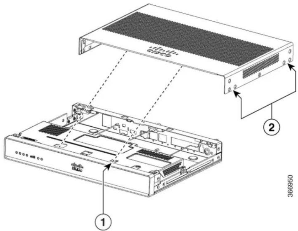
text_image
Technical diagram of a server rack with labeled components and part numbersFigure 13: Removing the Cover
| Screw holes (7 numbers on each side)2 |
Replacing the Cover
To replace the cover, perform the following steps.
Step 1 Read the Safety Warnings, on page 49 and disconnect the power supply before you begin.
Step 2 Confirm the router is turned off and disconnected from the power supply or power supplies. If a redundant power disconnect from the redundant power supply.
Step 3 Place the chassis on a flat surface.
Step 4 Locate the cover hooks on the mating slots and slide the cover towards the bezel side.
Step 5 Install seven screws on each side.
Locating Internal and External Slots for Modules
This section describes the locations of internal modules on the router motherboard. Internal modules inclu PoE daughter card on the Cisco1100 Series ISRs.
Figure 14: Module Location in the Cisco 1100 Series ISR
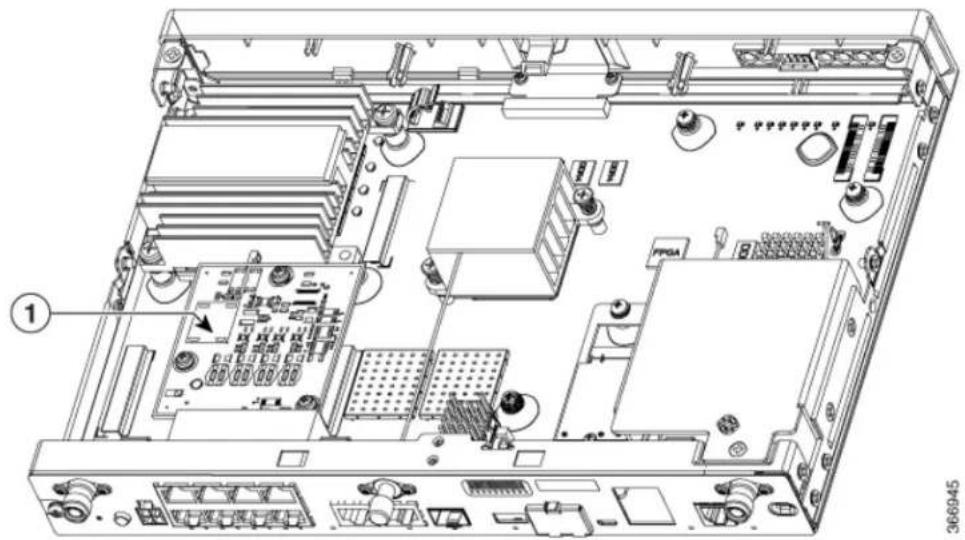
text_image
Technical diagram of an internal computer motherboard with labeled components and numbered parts| PoE Module1 |
Installing the Internal PoE Daughter Card
Use the following procedure to install an Internal PoE daughter card:
Step 1 Read the Safety Warnings and disconnect the power supply before you perform any module installation.
Step 2 Confirm the router is turned off and disconnected from the power supply.
Step 3 Open the chassis according to the instructions in the Removing the Chassis section.
Step 4 Locate the three metal standoff holes, and install the metal standoffs into the three holes. Make sure that the standoffs are straight when installed. Tighten them gently but firmly, to a torque of 6-8 in-lbf.
Step 5 Place the PoE daughter card on top of the three metal standoffs, lining up the screw holes in the PoE daughter card the metal standoffs.
Step 6 Gently push the PoE daughter card down towards the system board until it is firmly fixed.
Step 7 Insert the three M3 (48-0530-01) screws provided, through the PoE daughter card and into the metal standoffs. Tight the screws using a torque of 5 in-lb.
Step 8 Close the chassis cover according to the instructions in the Replacing the Cover section, and connect the power suppl cable.
Figure 15: Internal PoE Daughter Card Assembly
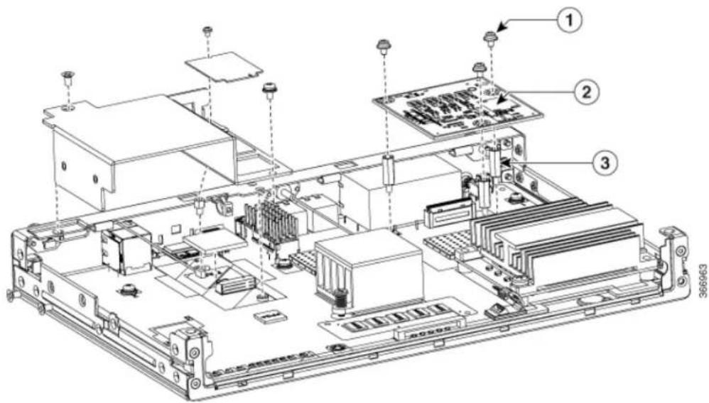
text_image
Technical diagram of an electronic device chassis with labeled components and connectors| PoE Daughter Card2Screws1 | |||
| Metal Standoffs3 |
Removing and Replacing the Internal PoE Daughter Card
Use the following procedure to remove and replace the Internal PoE daughter card:
Step 1 Read the Safety Warnings and disconnect the power supply before you remove or replace the module.
Step 2 Open the chassis, locate the PoE daughter card assembly.
Step 3 Remove the three M3 (48-0530-01) screws.
Step 4 Pull the PoE daughter card out of the connector. If replacing the card, insert the new PoE daughter card and tigh screws to a torque of 5 in-lb.
Step 5 Place the removed card in an anti-static bag to protect it from ESD damage.
Note To upgrade the PoE daughter card, follow the steps mentioned in the Installing the Internal PoE Daughter section.
Removing and Replacing the USB Flash Token Memory Stick
The Cisco 1100 Series ISRs contain port for a 1 GB flash token memory stick to store configurations of IOS XE consolidated packages.

Only Cisco USB Flash memory modules are supported by Cisco routers. Note

Caution
Do not remove a USB Flash memory module when issuing some file access command or a read/write operation to the Flash memory module when it is processing. The router might reload or the USB Flash memory module can be damaged. You can check to see if the USB activity LED on the router front panel is flashing, prior to the removal of the USB device
To remove and then replace a USB flash token memory stick from the router, follow these steps:
Step 1 Pull the memory stick from the USB port.
Step 2 To replace a Cisco USB Flash memory stick, simply insert the module into the USB port. The Flash memory mo can be inserted in only one way, and can be inserted or removed regardless of whether the router is powered up
What to Do Next
This completes the USB Flash memory installation procedure.
AC Power Supplies
Overview of the AC Power Supply
Power supply of the Cisco 1100 Series ISRs is an external AC to DC power adapter. The external power adapter DC power connector plugs in to the router 4-pin power connector, to power the unit.
Figure 16: Power Supply Unit

natural_image
Diagram of a Sony 36081 network switch with ports and connectors (no text labels beyond component identifiers)| Power Cable1 |
Installing and Removing SFP Modules
This section describes how to install optional small-form-factor pluggable (SFP) modules in the router to provide optical Gigabit Ethernet connectivity.
The SFP module installs into a slot on the router rear panel. When selected in Cisco IOS software, it is ass port gigabitethernet 0/0/0. The default is the built-in RJ-45 1000Base-T connector, which is enabled on this port.
Only SFP modules certified by Cisco are supported on the routers.
Table 12: SFPs Supported on the Router
| Cisco Model Number | IOS-XE Version | DescriptionMinimum |
| 3.15GLC-EX-SMD00BASE-EX SFP transceiver module, SMF, 1310nm, DOM |
| Cisco Model Number | IOS-XE Version | DescriptionMinimum |
| 3.10GLC-LH-SMGE SFP, LC connectorLX/LH transceiver | ||
| 9/1251000Base-ZXGLC-ZX-SM-X= | ||
| 3.10GLC-LH-SMDE SFP, LC connectorLX/LH transceiver; with DOM | ||
| 3.10GLC-SX-MMGE SFP, LC connector SX transceiver | ||
| 3.10GLC-SX-MMEE SFP, LC connector SX transceiver; with DOM | ||
| 3.10GLC-ZX-SM1000BASE-ZX SFP | ||
| 3.16.1GLC-ZX-SMID0BASE-ZX SFP; with DOM | ||
| 3.10GLC-FE-100FX0BASE-FX SFP for FE port | ||
| 3.10GLC-FE-100LIX0BASE-LX SFP for FE port | ||
| 3.10GLC-FE-100ZX0BASE-ZX SFP (80km) | ||
| 3.10GLC-FE-100EX0BASE-EX SFP (40km) | ||
| 3.11GLC-FE-100XID0BASE-BX10-D SFP | ||
| 3.11GLC-FE-100XID0BASE-BX10-U SFP | ||
| V02 | 3.10GLC-GE-100100 V02 SFP on GE ports |
| Cisco Model Number | IOS-XE Version | DescriptionMinimum |
| 3.16.1GLC-BX80 | 4D00BASE-BX80SFP, 1570NM | |
| 3.16.1GLC-BX80 | 4D00BASE-BX80SFP, 1490NM | |
| 3.16.1GLC-BX40 | 4D00BASE-BX40SFP, 1550NM | |
| 3.16.1GLC-BX40 | 4D00BASE-BX40SFP, 1310NM | |
| 3.10GLC-BX-D | 1000BASE-BXSFP, 1490NM | |
| 3.10GLC-BX-U | 1000BASE-BXSFP, 1310NM | |
| 3.13SFP-GE-S | 1000BASE-SXSFP transceiver module for MMF, 850-nm wavelength, extended operating temperature range and DOM support, dual LC/PC connector | |
| 3.10CWDM-SFP-1 | 4DWDM 1470NM SFP Gigabit Ethernet and 1G/2G FC | |
| 3.10CWDM-SFP-1 | 4DWDM 1490NM SFP Gigabit Ethernet and 1G/2G FC | |
| 3.10CWDM-SFP-1 | 5DWDM 1510NM SFP Gigabit Ethernet and 1G/2G FC | |
| 3.10CWDM-SFP-1 | 5DWDM 1530NM SFP Gigabit Ethernet and 1G/2G FC | |
| 3.10CWDM-SFP-1 | 50WDM 1550NM SFP Gigabit Ethernet and 1G/2G FC | |
| 3.10CWDM-SFP-1 | 50WDM 1570NM SFP Gigabit Ethernet and 1G/2G FC | |
| 3.10CWDM-SFP-1 | 50WDM 1590NM SFP Gigabit Ethernet and 1G/2G FC | |
| 3.10CWDM-SFP-1 | 60WDM 1610NM SFP Gigabit Ethernet and 1G/2G FC | |
| 3.10DWDM-SFP-3 | 60WDM SFP 1530.33 nm SFP (100 GHz ITU grid) | |
| 3.10DWDM-SFP-3 | 100WDM SFP 1531.12 nm SFP (100 GHz ITU grid) | |
| 3.10DWDM-SFP-3 | 100WDM SFP 1531.90 nm SFP (100 GHz ITU grid) | |
| 3.10DWDM-SFP-3 | 100WDM SFP 1532.68 nm SFP (100 GHz ITU grid) | |
| 3.10DWDM-SFP-3 | 100WDM SFP 1534.25 nm SFP (100 GHz ITU grid) | |
| 3.10DWDM-SFP-3 | 100WDM SFP 1535.04 nm SFP (100 GHz ITU grid) | |
| 3.10DWDM-SFP-3 | 582WDM SFP1535.82 nm SFP(100 GHz ITU grid) | |
| 3.10DWDM-SFP-3 | 68DWDM SFP1536.61 nm SFP(100 GHz ITU grid) | |
| 3.10DWDM-SFP-3 | 88DWDM SFP1538.19 nm SFP(100 GHz ITU grid) | |
| 3.10DWDM-SFP-3 | 88DWDM SFP1538.98 nm SFP(100 GHz ITU grid) | |
| 3.10DWDM-SFP-3 | 98DWDM SFP1539.77 nm SFP(100 GHz ITU grid) | |
| 3.10DWDM-SFP-4 | 108DWDM SFP1540.56 nm SFP(100 GHz ITU grid) | |
| 3.10DWDM-SFP-4 | 12DWDM SFP1542.14 nm SFP(100 GHz ITU grid) | |
| 3.10DWDM-SFP-4 | 12DWDM SFP1542.94 nm SFP(100 GHz ITU grid) | |
| 3.10DWDM-SFP-4 | 12DWDM SFP1543.73 nm SFP(100 GHz ITU grid) | |
| 3.10DWDM-SFP-4 | 12DWDM SFP1544.53 nm SFP(100 GHz ITU grid) | |
| 3.10DWDM-SFP-4 | 6DWDM SFP1546.12 nm SFP(100 GHz ITU grid) | |
| 3.10DWDM-SFP-4 | 6DWDM SFP1546.92 nm SFP(100 GHz ITU grid) | |
| 3.10DWDM-SFP-4 | 7DWDM SFP1547.72 nm SFP(100 GHz ITU grid) | |
| 3.10DWDM-SFP-4 | 8DWDM SFP1548.51 nm SFP(100 GHz ITU grid) | |
| 3.10DWDM-SFP-5 | 9DWDM SFP1550.12 nm SFP(100 GHz ITU grid) | |
| 3.10DWDM-SFP-5 | 10DWDM SFP1550.92 nm SFP(100 GHz ITU grid) | |
| 3.10DWDM-SFP-5 | 11DWDM SFP1551.72 nm SFP(100 GHz ITU grid) | |
| 3.10DWDM-SFP-5 | 12DWDM SFP1552.52 nm SFP(100 GHz ITU grid) | |
| 3.10DWDM-SFP-5 | 13DWDM SFP1554.13 nm SFP(100 GHz ITU grid) | |
| 3.10DWDM-SFP-5 | 14DWDM SFP1554.94 nm SFP(100 GHz ITU grid) | |
| 3.10DWDM-SFP-5 | 5DWDM SFP1555.75 nm SFP(100 GHz ITU grid) | |
| 3.10DWDM-SFP-5 | 6DWDM SFP1556.55 nm SFP(100 GHz ITU grid) | |
| 3.10DWDM-SFP-5 | 8DWDM SFP1558.17 nm SFP(100 GHz ITU grid) | |
| 3.10DWDM-SFP-5 | 9DWDM SFP1558.98 nm SFP(100 GHz ITU grid) | |
| 3.10DWDM-SFP-5 | 10DWDM SFP1559.79 nm SFP(100 GHz ITU grid) | |
| 3.10DWDM-SFP-6 | 11DWDM SFP1560.61 nm SFP(100 GHz ITU grid) |

Use the show controller command at the Cisco IOS prompt to determine whether you are using an SFP certified by Cisco.

Currently, GLC-GE-100FX V01 is not supported. Note
Installing SFPs
Removing SFP Modules
Follow these steps to remove an SFP from the router:
Step 1 Read the Safety Warnings section and disconnect the power supply before you perform any module replacement.
Step 2 Disconnect all cables from the SFP.
Warning Invisible laser radiation may be emitted from disconnected fibers or connectors. Do not stare into beams view directly with optical instruments. Statement 1051
Caution The latching mechanism used on many SFPs locks the SFP into place when cables are connected. Do n pull on the cabling in an attempt to remove the SFP.
Step 3 Disconnect the SFP latch.
Note SFP modules use various latch designs to secure the module in the SFP port. Latch designs are not linked to SFP model or technology type. For information on the SFP technology type and model, see the label on the SFP.
Tip Use a pen, screwdriver, or other small straight tool to gently release a bale-clasp handle if you cannot reach with your fingers.
Step 4 Grasp the SFP on both sides and remove it from the router.
Installing and Removing SFP Modules

text_image
CHAPTER 6Declaration of Conformity for RF Exposure
This product has been found to be compliant to the requirements set forth in CFR 47 Section 1.1307 addr RF Exposure from radio frequency devices as defined in Evaluating Compliance with FCC Guidelines for Human Exposure to Radio Frequency Electromagnetic Fields.
To maintain compliance, the minimum separation distance from the antenna to general bystander is 25 cm (9.8 inches) or more from the body of all persons.
• Declaration of Conformity of RF Exposure, page 63
Declaration of Conformity of RF Exposure
The following is the declaration of conformity of RF exposure for the United States and Canada:
United States
This product has been evaluated and found compliant to the requirements as set forth in CFR 47 Section 1.1307 addressing RF Exposure from radio frequency devices.
To maintain compliance, the minimum separation distance from the antenna to general bystanders is 25 c (9.8 inches) or more from the body of all persons.
Canada
This device complies with RSS-247 of the Industry Canada Rules. Operation is subject to the following conditions:
• This device may not cause harmful interference
- This device must accept any interference received, including interference that may cause undesired operation
Radiation Exposure Statement
This equipment complies with IC radiation exposure limits set forth in an uncontrolled environment. This equipment should be installed and operated with minimum distance 20 cm (7.87 in.) between the radiator at your body.
natural_image
Panoramic cityscape with modern skyscrapers under a bright sky, no visible text or signageINDEX
? command (ROM Monitor) 43, 44
1 GB flash token memory stick 53
C
chassis 31
desktop installation 31
confreg command (ROM Monitor) 44
displaying configuration register setting 44
connections 20
Ethernet 20
network 20
D
desktop installation 31
E
environment variables 41, 45, 46
displaying 45
entering 46
introduction 41,45
saving 46
Ethernet cable types 20
H
help command (ROM Monitor) 43
|
installation 18, 20, 31
desktop 31
site requirements 18
tools required tools required for installation 20
L
LAN 20,38
connections 38
interface types 20
N
network connections 20
P
packing list 24
power 18
requirements 18
power supplies 18
requirements 18
R
record keeping, site log 22
ROM monitor 46
exiting 46
ROM Monitor prompt 41
s
set command (ROM Monitor) 45
sync command (ROM Monitor) 46
T
Tables 18
power requirements 18
W
Warnings 20, 23, 38
lightning activity 38
restricted access 23
SELV circuit 20
qualified personnel 23