
RC-1043 - Régulateur DENON - Free user manual and instructions
Find the device manual for free RC-1043 DENON in PDF.


| Type | Remote Control Unit |
| Brand | Denon |
| Model | RC-1043 |
| Dimensions (W x H x D) | 52 x 243 x 21 mm |
| Weight (with batteries) | 175 g (approx. 6.2 oz) |
| Batteries | 2 x R6P/AA (included) |
| Operating Range | Up to 7 m (23 ft), horizontal angle up to 30° |
| Compatibility | Denon AVR-887 and other components with preset codes |
| Key Functions | Power, volume, input selection, surround mode, system setup, navigation |
| Preset Memory | Yes, for controlling non-Denon components |
| Punch Through Function | Yes, allows volume control from another device mode |
| LED Indicator | Yes, for operation feedback |
| Material | Plastic (est.) |
| Color | Black (est.) |
| Battery Life | Depends on usage; replace when unresponsive |
Frequently Asked Questions - RC-1043 DENON
User questions about RC-1043 DENON
0 question about this device. Answer the ones you know or ask your own.
Ask a new question about this device
Download the instructions for your Régulateur in PDF format for free! Find your manual RC-1043 - DENON and take your electronic device back in hand. On this page are published all the documents necessary for the use of your device. RC-1043 by DENON.
USER MANUAL RC-1043 DENON
The lightning flash with arrowhead symbol, within an equilateral triangle, is intended to alert the user to the presence of uninsulated "dangerous voltage" within the product's enclosure that may be of sufficient magnitude to constitute a risk of electric shock to persons.

The exclamation point within an equilateral triangle is intended to alert the user to the presence of important operating and maintenance (servicing) instructions in the literature accompanying the appliance.
WARNING:
TO REDUCE THE RISK OF FIRE OR ELECTRIC SHOCK, DO NOT EXPOSE THIS APPLIANCE TO RAIN OR MOISTURE.
SAFETY INSTRUCTIONS
- Read Instructions – All the safety and operating instructions should be read before the product is operated.
- Retain Instructions - The safety and operating instructions should be retained for future reference.
- Heed Warnings - All warnings on the product and in the operating instructions should be adhered to.
- Follow Instructions - All operating and use instructions should be followed.
- Cleaning – Unplug this product from the wall outlet before cleaning. Do not use liquid cleaners or aerosol cleaners.
- Attachments – Do not use attachments not recommended by the product manufacturer as they may cause hazards.
- Water and Moisture – Do not use this product near water – for example, near a bath tub, wash bowl, kitchen sink, or laundry tub, in a wet basement; or near a swimming pool; and the like.
- Accessories – Do not place this product on an unstable cart, stand, tripod, bracket, or table. The product may fall, causing serious injury to a child or adult, and serious damage to the product. Use only with a cart, stand, tripod, bracket, or table recommended by the manufacturer, or sold with
the product. Any mounting of the product should follow the manufacturer's instructions, and should use a mounting accessory recommended by the manufacturer.
- A product and cart combination should be moved with care. Quick stops, excessive force, and uneven surfaces may cause the product and cart combination to overturn.
- Ventilation – Slots and openings in the cabinet are provided for ventilation and to ensure reliable operation of the product and to protect it from overheating, and these openings must not be blocked or covered. The openings should never be blocked by placing the product on a bed, sofa, rug, or other similar surface. This product should not be placed in a built-in installation such as a bookcase or rack unless proper ventilation is provided or the manufacturer's instructions have been adhered to.
- Power Sources - This product should be operated only from the type of power source indicated on the marking label. If you are not sure of the type of power supply to your home, consult your product dealer or local power company. For products intended to operate from battery power, or other sources, refer to the operating instructions.
- Grounding or Polarization – This product may be equipped with a polarized alternating current line plug to plug having one blade wider than the other. This plug will fit into the power outlet only one way. This is a safety feature. If you are unable to insert the plug fully into the outlet, try reversing the plug. If the plug should still fail to fit, contact your electrician to replace your obsolete outlet. Do not defeat the safety purpose of the polarized plug.

- Power-Cord Protection - Power-supply cords should be routed so that they are not likely to be walked on or pinched by items placed upon or against them, paying particular attention to cords at plugs, convenience receptacles, and the point where they exit from the product.
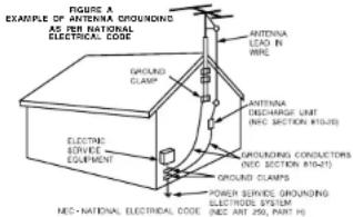
- Outdoor Antenna Grounding - If an outside antenna or cable system is connected to the product, be sure the antenna or cable system is grounded so as to provide some protection against voltage surges and built-up static charges. Article 810 of the National Electrical Code, ANSI/NFPA 70, provides information with regard to proper grounding of the most and supporting structure, grounding of the lead in wire to an antenna discharge unit, size of grounding conductors, location of antenna discharge unit, connection to grounding electrodes, and requirements for the grounding electrode. See Figure A.
- Lightning - For added protection for this product during a lightning storm, or when it is left unattended and unused for long periods of time, unplug it from the wall outlet and disconnect the antenna or cable system. This will prevent damage to the product due to lightning and power-line surges.
- Power Lines - An outside antenna system should not be located in the vicinity of overhead power lines or other electric light or power circuits, or where it can fall into such power lines or circuits. When installing an outside antenna system, extreme care should be taken to keep from touching such power lines or circuits as contact with them might be fatal.
- Overloading - Do not overload wall outlets, extension cords, or integral convenience receptacles as this can result in a risk of fire or electric shock.
- Object and Liquid Entry – Never push objects of any kind into this product through openings as they may touch dangerous voltage points or short-out parts that could result in a fire or electric shock. Never spill liquid of any kind on the product.
- Servicing - Do not attempt to service this product yourself as opening or removing covers may expose you to dangerous voltage or other hazards. Refer all servicing to qualified service personnel.
- Damage Requiring Service – Unplug this product from the wall outlet and refer servicing to qualified service personnel under the following conditions:
a) When the power-supply cord or plug is damaged,
b) If liquid has been spilled, or objects have fallen into the product,
c) If the product has been exposed to rain or water,
d) If the product does not operate normally by following the operating instructions. Adjust only those controls that are covered by the operating instructions as an improper adjustment of other controls may result in damage and will often require extensive work by a qualified technician to restore the product to its normal operation,
e) If the product has been dropped or damaged in any way, and
II When the product exhibits a distinct change in performance – this indicates a need for service.
- Replacement Parts - When replacement parts are required, be sure the service technician has used replacement parts specified by the manufacturer or have the same characteristics as the original part. Unauthorized substitutions may result in fire, electric shock, or other hazards.
- Safety Check – Upon completion of any service or repairs to this product, ask the service technician to perform safety checks to determine that the product is in proper operating condition.
- Wall or Ceiling Mounting - The product should be mounted to a wall or ceiling only as recommended by the manufacturer.
- Heat - The product should be situated away from heat sources such as radiators, heat registers, stoves, or other products (including amplifiers) that produce heat.
| FCC INFORMATION (For US customers) |
| 1. PRODUCTThis product complies with Part 15 of the FCC Rules. Operation is subject to the following two conditions: IN this product may not cause harmful interference, and 2) this product must accept any interference received, including interference that may cause undesired operation. |
| 2. IMPORTANT NOTICE: DO NOT MODIFY THIS PRODUCTThis product, when installed as indicated in the instructions contained in this manual, meets FCC requirements. Modification not expressly approved by DENON may void your authority, granted by the FCC, to use the product. |
| 3. NOTEThis product has been tested and found to comply with the limits for a Class B digital device, pursuant to Part 15 of the FCC Rules. These limits are designed to provide reasonable protection against harmful interference in a residential installation.This product generates, uses and can radiate radio frequency energy and, if not installed and used in accordance with the instructions, may cause harmful interference to radio communications. However, there is no guarantee that interference will not occur in a particular installation. If this product does cause harmful interference to radio or television reception, which can be determined by turning the product OFF and ON, the user is encouraged to try to correct the interference by one or more of the following measures:Reorient or relocate the receiving antenna.Increase the separation between the equipment and receiverConnect the product into an outlet on a circuit different from that to which the receiver is connected.Consult the local retailer authorized to distribute this type of product or an experienced radio/TV technician for help. |
This Class B digital apparatus complies with Canadian ICES-003.
NOTE ON USE
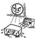 A void high temperaturesAllow for sufficient heat dispersion when installed in a rack. A void high temperaturesAllow for sufficient heat dispersion when installed in a rack. | 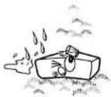 Keep the apparatus free from moisture, water, and dust. Keep the apparatus free from moisture, water, and dust. | 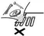 Do not let foreign objects into the apparatus. Do not let foreign objects into the apparatus. |
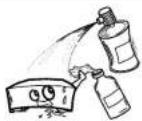 Do not let insecticides, benzene, and thinner come in contact with the apparatus. Do not let insecticides, benzene, and thinner come in contact with the apparatus. | ||
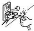 I handle the power cord carefullyHold the plug when unplugging the cord. I handle the power cord carefullyHold the plug when unplugging the cord. | 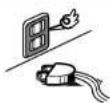 Unplug the power cord when not using the apparatus for long periods of time. Unplug the power cord when not using the apparatus for long periods of time. | |
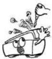 Never disassemble or modify the apparatus in any way Never disassemble or modify the apparatus in any way | ||
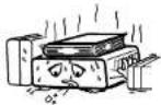 (For apparatuses with ventilation holes)Do not obstruct the ventilation holes. (For apparatuses with ventilation holes)Do not obstruct the ventilation holes. |
ENGLISH
Thank you for choosing the DENON AVR-887 AV Surround Receiver. This remarkable component has been engineered to provide superb surround sound listening with home theater sources such as DVD, as well as providing outstanding high fidelity reproduction of your favorite music sources. As this product is provided with an immense array of features, we recommend that before you begin hookup and operation that you review the contents of this manual before proceeding.
Contents
Getting Started
Accessories 2
Before using 3
Cautions on installation....3
About the remote control unit....3
Inserting the batteries....3
Operating range of the remote control unit 3
Front panel 4
Display 4
Rear panel 5
Remote control unit 5,6
Part names and functions
Easy Setup Procedure
Easy to setup flow 7
Speaker layout [Basic layout] 7
Speaker connections 8
Connecting a DVD player and monitor 9
Auto Setup/Room Equalizer (Room EQ) Functions
① Connecting a microphone 10
② Before performing the Auto Setup procedure 11
③ Perform the Auto Setup procedure....11
④ Assigning power amplifiers 11
⑤ Switching the front speaker 11
⑥ Starting Auto Setup 12
⑦ Checking and storing the measurement results 12
Error messages 13
Connecting Other Sources
Cable Indications 14
The video conversion function....15
Relationship between the video input signal and monitor output according to the video convert settings……15, 16
The analog video to HDMI conversion function....16
Connecting equipment with HDMI terminals
[To convert analog video signals to HDMI signals]....17
Connecting a TV/DBS tuner 17
Connecting a video camera or video game....17
Connecting a CD player 18
Connecting a turntable 18
Connecting the external inputs (EXT. IN) terminals 18
Connecting equipment with HDMI terminals 19
Connecting a DVD recorder....20
Connecting a VCR 20
Connecting a tape deck, CD recorder or MD recorder....21
Connecting the iPod ^® 21
Connecting the antenna terminals 22
Connecting the XM terminal 22
ZONE2 out connections 23
ZONE2 speaker out connections 23
Connecting the PRE OUT terminals 24
Connecting the power supply cord 24
Connecting the MULTI ZONE terminals
Basic Operation
Playing the input source 25
Turning the sound off temporarily (MUTING)....26
Listening over headphones 26
Switching the front speakers 26
Checking the currently playing program source, etc. 26
Switching the brightness of the display 26
Types of surround modes and their features 26, 27
Selecting the play mode (PURE DIRECT/DIRECT/STEREO)……27
Selecting the Dolby Digital and DTS Surround mode
(only with digital input) 28
Selecting the Dolby Pro Logic IIIx (Pro Logic II) mode....29
Selecting the DTS NEO:6 mode 30
Selecting the NEURAL SURROUND mode 30
Checking the input signals 30
Surround modes and parameters....31 - 33
Using the surround modes
Using the DENON original surround modes
Types of surround modes and their features....34
Selecting the DSP surround simulation 35
Setting the tone control 36
Adjusting the speaker volume 36
Using the fader function 36
Auto tuning 37
Manual tuning 37
Preset memory 38
Checking the preset stations 38
Recalling preset stations 38
Checking the XM signal strength and Radio ID 39
Channel selection 39
Category search 39
Listening to the radio
XM Satellite Radio 38
Advanced Operation
Night mode 40
User mode function
Storing the settings in the memory 40
Calling the settings out 40
Combining the currently playing sound
with the desired image (VIDEO SELECT function)....40
Personal memory plus function....40
Playing the iPod® 40
Listening to music....41
Viewing still pictures and videos
(only for iPods equipped with the slideshow / video function)....41
Disconnecting the iPod 41
Multi zone music entertainment system
Outputting a program source to amplifier, etc.,
in the ZONE2 room (ZONE2 SELECT mode) 43
Remote control unit operations during multi-source playback……43
Recording (audio and/or video) 44
About the memory functions....44
Initialization of the microprocessor (Reset) 44
Advanced Setup – Part 1
System setup items and default values 45 - 47
Navigating through the System Setup Menu
About the on screen display and front display 49
Audio Input Setup
Setting the Digital In Assignment 49
Setting the EXT. IN Subwoofer Level 50
Setting the iPod Assignment 50
Setting the Input Function Level 50
Setting the Function Rename 51
Setting the Tuner Presets 51, 52
Video Setup
Setting the HDMI In Assignment 53
Setting the Component In Assignment 53
Setting the Video Convert 54
Setting the HDMI Out Setup 54
Setting the Audio Delay 55
Setting the On Screen Display (IOSDI) 55
Advanced Playback
Setting the 2ch Direct/Stereo 56
Setting the Dolby Digital Downmix Option Setup 56
Setting the Auto Surround Mode 57
Setting the Manual Equalizer Setup 57
Option Setup
Setting the Power Amplifier Assignment 58
Setting the Volume Control 5B
Setting the Setup Lock 59
Advanced Setup – Part 2
Speaker Setup
Setting the Speaker Configuration 60
Setting the Subwoofer Setup 61
Setting the Distance....61
Setting the Channel Level 62
Setting the Crossover Frequency 63
Others Setup
Setting the Room Equalizer Setup 63
Setting the Direct Mode Setup 64
Check the parameter 64
Operating the remote control unit
Operating DENON audio components 65
Setting the preset memory function....65
Operating a component stored in the preset memory....66 - 68
Setting the punch through function....69
Additional Information 70 \~ 72
Troubleshooting 72, 73
Specifications 74
List of preset codes ......End of this manual
Getting Started
Accessories
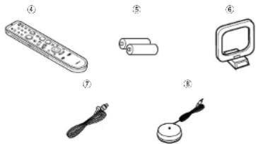
Check that the following parts are attached in addition to the main unit:
① Operating instructions ....1
② Warranty (for North America model only)....1
③ Service station list ....1
④ Remote control unit (RC-1043)....1
⑤ R6P/AA batteries 2
⑥ AM loop antenna ....1
⑦ FM indoor antenna ....1
⑧ Setup microphone (DM-S205) (Approx. 20 ft / 6 m) .....1
natural_image
Illustration of six different household appliances and devices, including a remote control, rolled documents, computer monitor, cable, and earbell (no text or symbols present)ENGLISH
Getting Started Getting Started
Before using
Pay attention to the following before using this unit:
- Moving the unit.
To prevent short-circuits or damaged wires in the connection cables, always unplug the power supply cord and disconnect the connection cables between all other audio components when moving the unit.
• Cautions on using mobile phones.
Using a mobile phone near this unit may result in noise. If so, move the mobile phone away from this unit when it is in use. - B before turning the power operation button on.
Check once again that all connections are correct and that there are not problems with the connection cables. Always set the power operation button to the standby position before connecting and disconnecting connection cables. - Store the operating instructions in a safe place.
After reading the operating instructions, store them in a safe place as they could come in handy in the future. - Whenever the power operation button is in the STANDBY state, the unit is still connected to AC line voltage.
Please be sure to turn off the power operation button or unplug the cord when you leave home for, say, a vacation. - Note that the illustrations in these instructions may differ from the actual unit for explanation purposes.
Cautions on Installation
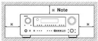
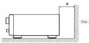
Note:
For heat dispersal, do not install this unit in a confined space such as a bookcase or similar enclosure.
natural_image
Simple line drawing of a rectangular container with a wall and side supports, no text or symbols present.About the remote control unit
In addition to controlling the AVR-887, the attached remote control unit (RC-1043) can also be used to control the following products:
① DENON component products
② Component products other than DENON:
- Set using the preset memory function (page 65).
Inserting the batteries
① Remove the remote control unit's rear cover.
② Set two R6P/AA batteries in the battery compartment in the indicated direction.
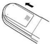
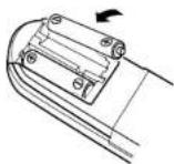
③ Put the rear cover back on.
Notes on batteries:
- Replace the batteries with new ones if the set does not operate even when the remote control unit is operated nearby the unit. (The attached batteries are only for verifying operation.)
- When inserting the batteries, be sure to do so in the proper direction, following the "⊕" and "⊖" marks in the battery compartment.
• To prevent damage or leakage of battery fluid:
- Do not use a new battery together with an old one.
- Do not use two different types of batteries.
- Do not short-circuit, disassemble, heat or dispose of batteries in flames.
- Remove the batteries from the remote if it will not be in use for long periods.
- If the battery fluid should leak, carefully wipe the fluid off the inside of the battery compartment and insert new batteries.
- When replacing the batteries, have the new batteries ready and insert them as quickly as possible.
Operating range of the remote control unit
- Point the remote control unit at the remote sensor when operating it.
- The remote control unit can be used from a distance of approximately 23 feet/7 meters, at a horizontal angle of up to 30^ with respect to the sensor.
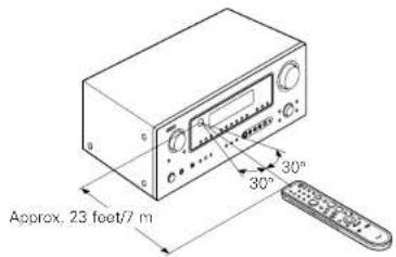
NOTE:
- It may be difficult to operate the remote control unit if the remote sensor is exposed to direct sunlight or strong artificial light.
Getting Started Getting Started
Part names and functions
For details on the functions of these parts, refer to the pages given in parentheses ( ).
Front panel
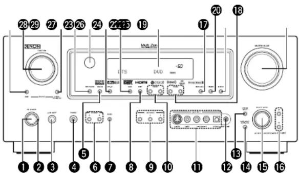
① Power operation button
(ON/STANDBY)....(11)
② Power indicator ……(11)
③ Power switch .....(11, 44)
4 Headphones jack (PHONES)....(26)
⑤ ANALOG button ……(25)
⑥ SPEAKER buttons....(26)
⑦ ZONE2 button....(43)
8 SHIFT button (38)
9 USER MODE buttons ......(40)
⑩ PRESET buttons....(37)
⑪ V.AUX INPUT terminals
Remove the cap covering the terminals when you want to use them.
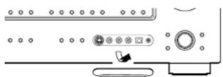
⑫ SETUP MIC jack .....(10)
⑬ SYSTEM SETUP button .....(11)
14 SURR. MODE/SURR. PARA button....(25, 35)
15 SELECT/ENTER knob ......(11, 35)

- The SELECT/ENTER knob on the main unit operates in the same way as the CURSOR ◀ and ▷ buttons on the remote control unit.

- The control functions in the same way as the CURSOR < button when turned counterclockwise,
as the CURSOR ▷ button when turned clockwise. - The control functions in the same way as the ENTER button when pressed the knob.
⑯ Cursor buttons (△, ▽)……(11)
⑰ MASTER VOLUME control knob......(25)
⑱ TUNING buttons (▲, ▼) ......(37)
19 STATUS button....(26)
20 DIMMER button....(26)
② VIDEO SELECT button .....(40)
22 Display
23 BAND button....(37)
24 EXT. IN button (25)
25 Remote control sensor....(3)
26 INPUT MODE button....(25)
⑳ ZONE2/ REC SELECT button....(43)
28 FUNCTION knob (25)
29 MAIN button ......(25)
Display
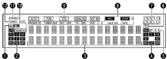
① Input signal indicators
② Input signal channel indicators
- The audio channel(s) included in the input signal light(s).
• This lights when the digital signal is inputted.
③ Information display
④ Output signal channel indicators
The audio channels that can be output light.
⑤ Speaker indicators
This lights corresponding to the settings of the front speakers of the various surround modes.
⑥ ZONE2 output indicator
⑦ Master volume indicator
This displays the volume level.
The Setup item number is displayed in System Setup.
⑧ ZONE2/REC SELECT INDICATORS
Lights while selecting the ZONE2 or REC SELECT mode. (Off when the "SOURCE" is selected.)
⑨ Input mode indicators
10 AUTO indicator
This lights when the broadcast station is selected in the AUTO tuning mode.
11 STEREO Indicator
This lights when an FM stereo broadcast has been received.
⑫ TUNED Indicator
This lights when an FM/AM broadcast has been received.
ENGLISH
ENGLISH
Getting Started Getting Started
Rear panel
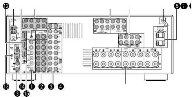
① DIGITAL terminals
(Optical/Coaxial) (9)
②VIDEO/S-VIDEO terminals....(9)
③ AUDIO terminals....191
④ Speaker terminals ..... [8]
⑤ AC outlets ......(24)
⑤ Power supply cord ......(24)
⑦ PRE OUT terminals (24)
⑧ COMPONENT VIDEO terminals....(9)
⑨ EXT. IN terminals (18)
⑩ DOCK CONTROL jack .....(21)
⑪ ANTENNA terminals ......(22)
⑫ HDMI terminals....(19)
⑬ SIGNAL GND terminal .....(18)
⑭ REMOTE CONTROL jacks .....(23)
⑮ XM terminal .....(22)
Remote control unit
![[ Front ] Indicator ....(65) Function buttons ....(25) System buttons ....(66 ~ 68) VIDEO SELECT/SETUP button ....(40, 66) Cursor buttons (△△△△△) ....(11) ON SCREEN/DISPLAY button ....(26, 66) DIMMER/MENU button ....(26, 66) Remote control signal transmitter....(3) Power buttons ....(11) Tuner system/ System buttons ....(37, 67) Master volume control buttons....(25) MUTING button ....(26) NIGHT/AUDIO button ....(40, 66) CH SELECT/ ENTER button ....(11, 36) STATUS/ RETURN button ....(26, 66) Mode selector switches....(11, 85)](/content/2026/05/817266/images/fe946d7193f634f9a00b323504cf8398c3cb96f8aba0c67975aaa6d2840443de.jpg)
NOTE:
- If buttons on the front or rear are pressed strongly, the button on the opposite side will be activated too.
Getting Started Getting Started
![[ Rear ] ZONE2 buttons......(43) Function / Number buttons......(25, 66) Tuner system/ System buttons......(37, 66) TEST TONE/ DISPLAY button......(62, 66) Cursor buttons (▲▼▼▼▼▼▼▼▼▼▼▼▼▼▼▼▼▼▼▼▼▼▼▼▼▼▼▼▼▼▼▼▼▼▼▼▼▼▼▼▼▼▼▼▼▼▼▼▼▼▼▼▼▼▼▼▼▼▼▼▼▼▼▼▼▼▼▼▼▼▼▼▼▼▼▼▼▼▼▼▼▼▼▼▼▼▼▼▼▼▼▼▼▼▼▼▼▼▼▼▼▲ MAIN buttons......(43) SURROUND MODE buttons......(27) SYSTEM SETUP/SETUP button......(11, 66) SURROUND PARAMETER/ AUDIO button......(25, 66) ENTER button......(11) INPUT MODE/ RETURN button......(25, 66)](/content/2026/05/817266/images/9b2c6937272837e0e4f8cbcefa02f0e636ae3c610177a2511b3861a2766b6d1d.jpg)
NOTE:
- If buttons on the front or rear are pressed strongly, the button on the opposite side will be activated too.
ENGLISH
Easy Setup Procedure
Easy Setup Procedure
- This section contains the basic steps necessary to configure the AVR-887 according to your listening room environment and the source equipment and loudspeakers you are using.
- To set the sound field manually (page 60 - 63).
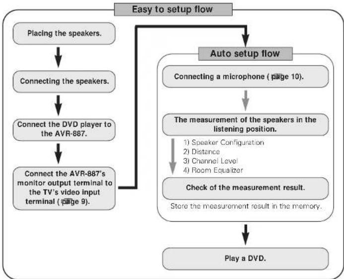
flowchart
graph TD
    A["Placing the speakers."] --> B["Connecting the speakers."]
    B --> C["Connect the DVD player to the AVR-887."]
    C --> D["Connect the AVR-887's monitor output terminal to the TV's video input terminal (page 9)."]
    D --> E["Auto setup flow"]
    E --> F["Connecting a microphone (page 10)."]
    F --> G["The measurement of the speakers in the listening position."]
    G --> H["1) Speaker Configuration\n2) Distance\n3) Channel Level\n4) Room Equalizer"]
    G --> I["Check of the measurement result.\nStore the measurement result in the memory."]
    I --> J["Play a DVD."]
Speaker layout [Basic layout]
Example of basic layout with eight speakers and a monitor.
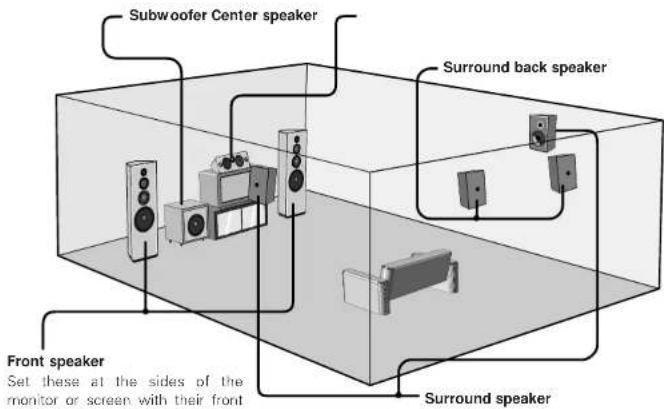
![DENON RC-1043 - Speaker layout [Basic layout] - 2](/content/2026/05/817266/images/96c60f6ea32121e52bdf1d4ce1aa547e681b28f3a8cf0e929e068bac6b59471c.jpg)
- Do not plug in the power supply cord until all connections have been completed.
Easy Setup Procedure
ENGLISH
Speaker connections
Connect the speaker terminals with the speakers making sure that like polarities are matched with , with .
NOTE:
When making connections, take care that none of the individual conductors of the speaker cable come in contact with adjacent terminals, with other speaker cable conductors, or with the rear panel and screws.
NEVER touch the speaker terminals when the power is on. Doing so could result in electric shocks.
Connecting the speaker cables

- Loosen by turning counterclockwise
Either tightly twist or terminate the core vires.
- Insert the cable.

- Tighten by turning clockwise.
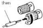
Connecting banana plugs
Turn clockwise to tighten, then insert the banana plug.
□ Speaker impedance
| ImpedanceSpeaker | |
| 6 ~ 16 Ω/ohmsFrom A, B | |
| 12 ~ 16 Ω/ohmsFront A+B | |
| Center | 6 - 16 Ω/ohms |
| Surround | |
| Surround back / ZONE2 |
Note on speaker impedance
When using speakers with an impedance below the designated value (for example 4 Ω/chms), playing for long periods of time with the volume high could cause the temperature to rise, activating the protection circuit.
When the protection circuit is activated, the output to the speakers is cut off and the power indicator blinks. If this happens, unplug the power cord, wait for the set to cool off and improve ventilation around the unit. Also check the wiring of the input cables and the speaker cables. After doing this, plug the power cord back in and turn the unit's power back on. If the protection circuit is activated again even though there are no problems with the wiring or the ventilation around the unit, switch off the power and contact a DENON service center.
Connections
- With the AVR-887, up to ten speakers can be connected for surround playback.
- When making connections, also refer to the operating instructions of the other components.
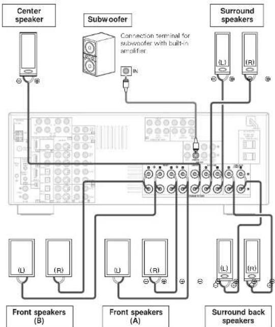
flowchart
graph TD
    A["Center speaker"] --> B["Subwoofer"]
    B --> C["Surround speakers"]
    C --> D["Front speakers (A)"]
    C --> E["Front speakers (B)"]
    C --> F["Front speakers (C)"]
    C --> G["Front speakers (D)"]
    style A fill:#f9f,stroke:#333
    style B fill:#ccf,stroke:#333
    style C fill:#cfc,stroke:#333
    style D fill:#fcc,stroke:#333
    style E fill:#cff,stroke:#333
    style F fill:#ffc,stroke:#333
    style G fill:#fcc,stroke:#333
When using only one surround back speaker, connect it to the left channel.
ENGLISH
Easy Setup Procedure
Easy Setup Procedure
Connecting a DVD player and monitor
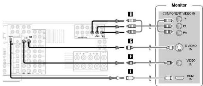
• To connect the video output from the DVD player to the AVR-BB7, you only need to choose one connection type. For more information about the video up conversion function (page 15).
- To connect the digital audio output from the DVD player, you can choose from either the coaxial or optical connections. If you choose to use the coaxial connection, it needs to be assigned. For more information about Digital Input Assignment (page 49).
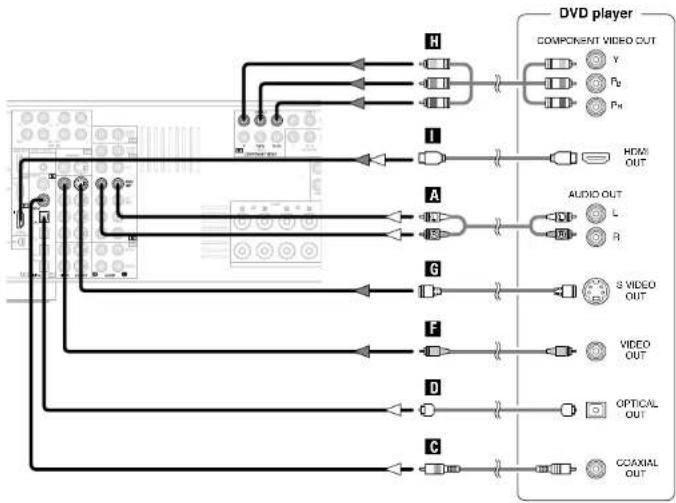
flowchart
graph TD
    A["Component"] --> B["DVD player"]
    B --> C["COMPONENT VIDEO OUT"]
    B --> D["HYM OUT"]
    B --> E["AUDIO OUT"]
    B --> F["S VIDEO OUT"]
    B --> G["VIDEO OUT"]
    B --> H["OPTICAL OUT"]
    B --> I["CCAXIAL OUT"]
* Audio signal flow is shown with white arrows, video signal flow is shown with gray arrows.

- Connect a non-DVD video disc player (such as a laser disc, VCD/SVCD, or future high definition disc player) to the DVD/VDP terminals in the same way.
- For best picture quality (especially with progressive DVD and other high definition sources), choose the component video or HDMI connection to your monitor. S-Video and composite video outputs are also provided if your monitor does not have component video inputs.
flowchart
graph TD
    A["Input Module"] --> B["Sensor 1"]
    A --> C["Sensor 2"]
    A --> D["Sensor 3"]
    A --> E["Sensor 4"]
    A --> F["Sensor 5"]
    A --> G["Sensor 6"]
    A --> H["Sensor 7"]
    A --> I["Sensor 8"]
    A --> J["Sensor 9"]
    A --> K["Sensor 10"]
    L["Monitor"] --> M["COMPONENT VIDEO IN"]
    M --> N["Y"]
    M --> O["Ps"]
    M --> P["Ps"]
    M --> Q["S VIDEO IN"]
    M --> R["VIDEO IN"]
    M --> S["HDMI IN"]

- The AVR-887 is equipped with HDMI terminals, so it can be connected to a DVD player or monitor using an HDMI cable.
- The component video input and/or output terminals may be labelled differently on some monitors or video components. Check the owner's manuals for other components for further information.
- Audio signals are only output from the HDMI monitor out terminal when audio signals are input to the HDMI input terminal.
- When connecting the AVR-887 and DVD player using an HDMI cable, also connect the AVR-887 and monitor using an HDMI cable (page 19).
Easy Setup Procedure Easy Setup Procedure
![SYSTEM SETUP △▽ ◀>, ENTER [ON/SOURCE] ENTER △▽◀▶ [MODE SELECTOR 1] SYSTEM SETUP △▽◀▶ ENTER](/content/2026/05/817266/images/ea173f8c60db0bfca5d6f081b6d29954a37e28d829470ffea7f4fb57ec3809af.jpg)
![About the button names in this explanation < > : Buttons on the main unit [ ] : Buttons on the remote control unit Button name only : Buttons on the main unit and remote control unit](/content/2026/05/817266/images/e7ec9ab89bcc001cd69a1ba945bef7771d9e04e333af768c35b894ebe0c31ba0.jpg)
Auto Setup/Room Equalizer (Room EQ) Functions
- The AVR-887's auto setup and room equalizer functions use the attached microphone to measure the acoustic properties in the room and automatically make the optimum settings.
- When the auto setup procedure is performed, one of the following three correction curves can be selected for the room equalizer function.
Normal:
Adjust the frequency response of all speaker suitable for general surround system.
Front:
This adjusts the characteristics of each speaker to the characteristics of the front speakers.
Flat:
This the frequency response of all speakers flat. This mode is optimum for playing multi-channel signal music.

• To make the sound field settings manually (page 60 \~ 63).
① Connecting a microphone
1 Connect the attached setup microphone to
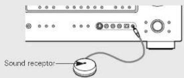
2 Mount the setup microphone on a camera tripod, etc., and set with the receptor pointing towards the ceiling.
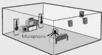
* Place the setup microphone's sound receptor at the height of the ears in the listening position.
※ It is not possible to measure properly if there are any obstacles between the speakers and microphone. Check that there are no obstacles.
NOTE:
- Once the settings are completed, disconnect the setup microphone.
ENGLISH
ENGLISH
Easy Setup Procedure Easy Setup Procedure
② Before performing the Auto Setup procedure
1 Turn on your subwoofer.
※ Set the volume to halfway and set the crossover frequency to the maximum or Low pass filter off if your subwoofer can adjust the output volume and the crossover frequency.
※ Some subwoofers have a standby mode. Be sure to turn this function off before performing the Auto Setup procedure.
2 Turn on your monitor.
3 Press
ON:
The power indicator lights red
OFF:
The power turns off and the indicator is off.
4 Press
• The power indicator blinks green and the power turns on.
5 Set [MODE SELECTOR 1] to "AUDIO".
③ Perform the Auto Setup procedure
1 Press SYSTEM SETUP.
2 Press ∧△ ∨ select "Auto Setup / Room EQ", then press ENTER.
3 Press ∧△ to select "Auto Setup", then press ENTER.
The message "Connect Microphone" is displayed if no microphone is connected. If so, connect the auto setup microphone.
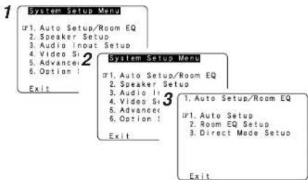

- "System Setup Menu" is not displayed when using headphones.
④ Assigning power amplifiers
The surround back output can be assigned to the "Front" or "ZONE2" output.
Press △△ ▽to select "Power Amp Assign", then press ◀◀ ▶to set.
Surround Back:
Assign to use as surround back speaker.
ZONE2:
Assign to use as "ZONE2" speakers.
Front A. Front B
Assign to use the "Front A" or "Front B" speakers with bi-amp connections.
* When assigned to "Front" or "ZONE2", skip the surround back channel measurement.
* During the auto setup procedure, test tones are not output to "ZONE2".
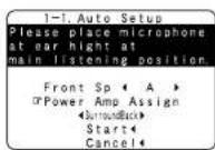
⑤ Switching the front speaker
Press to select "Front Sp", then press to select the speaker.

Easy Setup Procedure Easy Setup Procedure
⑥ Starting Auto Setup
Press △△ to select "Start", then press ◀.
- Start the measurements.
* Measurement of each channel is performed as follows:

*1: The subwoofer speaker is measured twice.
*2: Not displayed when "ZONE2" and "Front" are set at "Setting the Power Amplifier Assignment" (page 58).
- After each channel is measured, "Calculating" appears.
- The display switches to the Auto Setup check screen automatically.
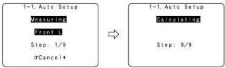
flowchart
graph LR
    A["1-1. Auto Setup\nMeasuring\nFront L\nStep: 1/9\nCancel"] --> B["1-1. Auto Setup\nCalculating\nStep: 9/9"]
NOTE:
- Do not change the speaker connections or subwoofer volume after making the measurements.
- Do not turn off the power while the data is being stored.
Cautions during measurements:
- Loud test tones are output during the measurements. Be careful for example when small children are nearby.
- Proper measurements may not be possible if there are obstacles between the speaker and the setup microphone.
- During the measurements, do not stand between or near the speakers and setup microphone.
- To avoid influencing the measurements, turn off the power of air-conditioners or any other equipment producing sound in the room. Perform the measurements with the room as quiet as possible.
- Measurement is cancelled when VOLUME is operated while the Auto Setup is performed.
□ About automatic retry
To confirm the results of the measurements, remeasurement is automatically performed.
Remeasurement is performed up to two times. During this time, "Retry1" or "Retry2" is displayed on the screen.
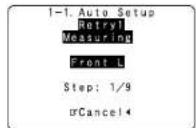
ENGLISH
⑦ Checking and storing the measurement results
1 Press △△ to select an item, then press ENTER.
* The measurement results of each item can be checked here.
2 After checking, press ENTER, then press △ △ to set.
Store:
All the settings are stored in the memory.
Retry:
Perform the measurement again.
Measurement is repeated.
Cancel:
Cancel the auto setup settings.
3 When "Store" is selected: Press ◀.
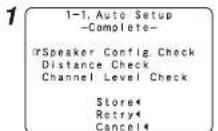
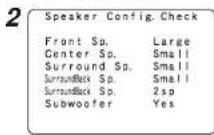
Example: Speaker Configuration Check

- When measurements have been made using the measurement microphone, speakers with a built-in filter such as subwoofers might be set with a value that differs from the physical distance because of the internal electrical delay.
ENGLISH
Easy Setup Procedure Easy Setup Procedure
Error messages
• These error screens may be displayed when performing Auto Setup measurement and the automatic measurements can not be completed because of the speaker arrangement, measurement environment, or other factors. Please check the following matters, reset the pertinent items, and measure again.
- When there is too much noise in the room, the speakers may not be detected properly. Should this happen, perform the measurements when the noise level is low, or switch off the power of the equipment that is producing the noise for the duration of the measurements.
Press △△ to select the items, then press ◀.
| MeasuresCauseExample | ||
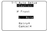 | 1 This screen will be displayed when the speakers required for producing suitable reproduction have not been detected. | • Check that the pertinent speakers are properly connected. |
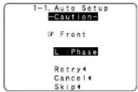 | 2 This screen will be displayed when the speaker polarity is connected in reverse. | • Check the polarity of the pertinent speakers. For some speakers, this screen may be displayed even though the speakers are properly connected.If so, select "Skip". |
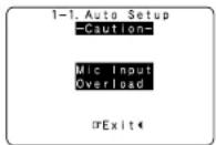 | 3 This screen will be displayed when accurate measurements cannot be made due to the input level of the microphone being too high. | • Set up the speakers so that their position is farther away from the listening position.• Lower the volume of the subwoofer speaker. |
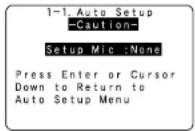 | 4 This screen will be displayed when the measurement microphone is not connected. | • Connect the measurement microphone to the microphone connector. |
Connecting Other Sources
Cable indications
The hookup diagrams on the subsequent pages assume the use of the following optional connection cables (not supplied).
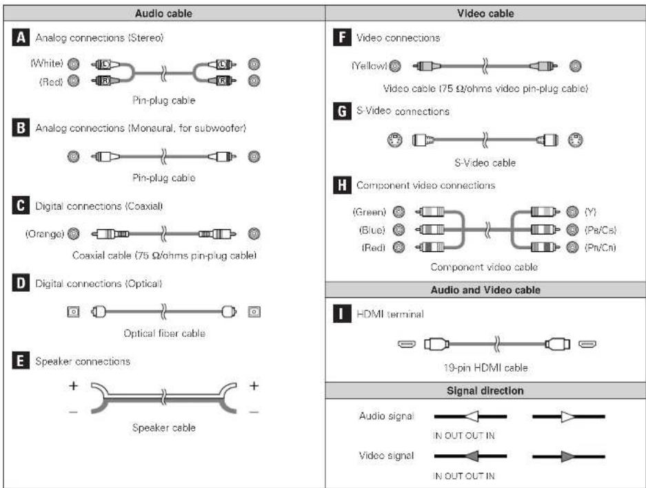
NOTE:
- Do not plug in the power supply cord until all connections have been completed.
- When making connections, also refer to the operating instructions of the other components.
- Be sure to connect the left and right channels properly (left with left, right with right).
- Do not bundle power cords together with speaker cables. Doing so could result in humming or noise.
ENGLISH
Connecting Other Sources Connecting Other Sources
The video conversion function
- Even if the formats of the video signals from the various players differ, the different formats can be converted and the signals output to the monitor from a single video output terminal. We recommend outputting with the format offering the highest quality video signals possible.
- With analog video signal connections, generally quality is higher in the order shown below.
The flow of the video signals.
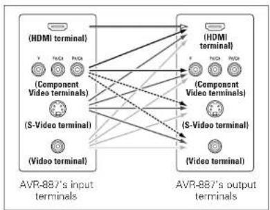
flowchart
graph LR
    subgraph_Input_Terminals["AVR-887's input terminals"]
        A1["(HDMI terminal)"]
        A2["(Component Video terminals)"]
        A3["(S-Video terminal)"]
        A4["(Video terminal)"]
    end
    subgraph_Output_Terminals["AVR-887's output terminals"]
        B1["(HDMI terminal)"]
        B2["(Component Video terminals)"]
        B3["(S-Video terminal)"]
        B4["(Video terminal)"]
    end
    A1 --> B1
    A1 --> B2
    A1 --> B3
    A1 --> B4
    A2 --> B1
    A2 --> B2
    A2 --> B3
    A2 --> B4
    A3 --> B1
    A3 --> B2
    A3 --> B3
    A3 --> B4
    A4 --> B1
    A4 --> B2
    A4 --> B3
    A4 --> B4
----: only 480/576i
Relationship between the video input signal and monitor output according to the video convert settings
| Video convert | Input signals | MONITOR OUT | ||||||
| VIDEOS-VIDEO COMPONENT HDMI | VIDEOS-AVIDE | |||||||
| ON | XX | XX | XXX | XX | XX | XX XX | ||
| XX | XX | XXXO | VIDEO | VIDEO | VIDEO | VIDEO | ||
| XX | XX | OOXX | S-VIDEO | S-VIDEO | S-VIDEO S-VIDEO | |||
| XX | XX | OOO | SAVIDEO | S-VIDEO | S-VIDEO S-VIDEO | |||
| XX | O(120p) | XXX | XX | COMPONENT | XXX XX | |||
| XX | O(480p - 720p) | XXX | COMPONENT | COMPONENT | XXX XX | |||
| XX | O(480/576i) | XXX | COMPONENT | COMPONENT | COMPONENT | COMPONENT | ||
| XX | O(120p) | XXXO | VIDEO | COMPONENT *1 | VIDEO | VIDEO | ||
| XX | O(480p - 720p) | XXXO | COMPONENT *1 | COMPONENT *1 | XX X3 | VIDEO | ||
| XX | O(480/576i) | XXXO | COMPONENT *1 | COMPONENT *1 | COMPONENT | VIDEO | ||
| XX | O(120p) | OOXX | S-VIDEO | COMPONENT *2 | S-VIDEO S-VIDEO | |||
| XX | O(480p - 720p) | OOXX | COMPONENT *2 | COMPONENT *2 | S-VIDEO | S-VIDEO | ||
| XX | O(480/576i) | OOXX | COMPONENT *2 | COMPONENT *2 | S-VIDEO | S-VIDEO | ||
| XX | O(120p) | OOO | S-VIDEO | COMPONENT *2 | S-VIDEO S-VIDEO | |||
| XX | O(480p - 720p) | OOO | COMPONENT *2 | COMPONENT *2 | S-VIDEO | S-VIDEO | ||
| XX | O(480/576i) | OOO | COMPONENT *2 | COMPONENT *2 | S-VIDEO | S-VIDEO | ||
| CO | XX | XXX | HDMI | XX | XXX | |||
| CO | XX | XXXO | HDMI *1 | VIDEO | VIDEO | VIDEO | ||
| CO | XX | OOXX | HDMI *2 | S VIDEO | S VIDEO S VIDEO | |||
| CO | XX | OOO | HDMI *2 | S VIDEO | S VIDEO S VIDEO | |||
| CO | O(other than 480/576i) | XXX | HDMI | COMPONENT | XXX XX | |||
| CO | O(480/576i) | XXX | HDMI | COMPONENT | COMPONENT | COMPONENT | ||
| CO | O(120p) | XX | OO | HDMI *1 | COMPONENT *1 | VIDEO | VIDEO | |
| CO | O(480p - 720p) | XX | OO | HDMI *1 | COMPONENT *1 | XX X3 | VIDEO | |
| CO | O(480/576i) | XXXO | HDMI *1 | COMPONENT *1 | COMPONENT | VIDEO | ||
| CO | O(other than 480/576i) | OOXX | HDMI *2 | COMPONENT *2 | S-VIDEO S-VIDEO | |||
| CO | O(480/576i) | OOXX | HDMI *2 | COMPONENT *2 | S-VIDEO S-VIDEO | |||
| CO | O(other than 480/576i) | OOO | HDMI *2 | COMPONENT *2 | S-VIDEO S-VIDEO | |||
| CO | O(480/576i) | CO | OO | HDMI *2 | COMPONENT *2 | S-VIDEO | S-VIDEO | |
OQ Signal input
xx: No signal
480p - 720p : 480p/576p/1090/720p

- The video conversion function is compatible with the following format: NTSC, PAL, SECAM, NTSC4.43, PAL-N, PAL-M and PAL-80.
- When SECAM signals of video input are up converted, the signals are output in PAL format from the S-Video terminal.
- Signals up converted to HDMI are output to the HDMI monitor with the resolution at which they are input. Note that resolutions of 1080p are not handled.
XX : Not output
*1 : On screen display superimposed on video signal and output
*2 On screen display superimposed on S-Video signal and output.
*3. Video signals are output when the "Analog to HDMI convert" is set to "OFF".
COMPONENT : On screen display only displayed for SYSTEM SETUP, SURROUND PARAMETER and ON SCREEN buttons.
HDMI : The on screen display is displayed when the "Analog to HDMI convert" is set to "ON".
: Video signals are not output when the "Analog to HDMI convert" is set to "OFF".
Connecting Other Sources Connecting Other Sources
| Video convert | S-VIDEO MONITOR OUT | Input signals | MONITOR OUT | ||||||
| VIDEOS-VIDEO COMPONENT-FDMI | VIDEOS-VIDEO | ||||||||
| OFF | - | × × | × × | × × | × × | × × | × × | × × | × × |
| - | × × | × × | × | O | × × | × × | × × | VIDEO | |
| - | × × | × × | O | × | × × | × × | S-VIDEO | × × | |
| Used | × × | × × | O | O | × × | × × | S-VIDEO | VIDEO *2 | |
| Not used | × × | × × | O | O | × × | × × | - | VIDEO | |
| - | × × | O | × | × | × × | COMPONENT | × × | × × | |
| - | × × | O | × | O | × × | COMPONENT × 1 | × × | VIDEO | |
| - | × × | O | O | × | × × | COMPONENT × 2 | S-VIDEO | × × | |
| Used | × × | O | O | O | × × | COMPONENT × 2 | S-VIDEO | VIDEO *2 | |
| Not used | × × | O | O | O | × × | COMPONENT × 1 | - | VIDEO | |
| - | O | × | × | × | HDMI | × | × | × | |
| - | O | × × | × | O | HDMI | × × | × × | VIDEO | |
| - | O | × × | O | × | HDMI | × × | S-VIDEO | × × | |
| Used | O | × × | O | O | HDMI | × × | S-VIDEO | VIDEO *2 | |
| Not used | O | × × | O | O | HDMI | × × | - | VIDEO | |
| - | O | O | × | × | HDMI | COMPONENT | × × | × × | |
| - | O | O | × | O | HDMI | COMPONENT *1 | × × | VIDEO | |
| - | O | O | O | × | HDMI | COMPONENT *2 | S-VIDEO | × × | |
| Used | O | O | O | O | HDMI | COMPONENT *2 | S-VIDEO | VIDEO *2 | |
| Not used | O | O | O | O | HDMI | COMPONENT *1 | - | VIDEO | |
O: Signal input
XX No signal
XX : Net output
※1 : On screen display superimposed on video signal and output.
*2 : On screen display superimposed on S-Video signal and output.
COMPONENT : On screen display only displayed for SYSTEM SETUP, SURROUND PARAMETER and ON SCREEN buttons.
HDMI : The on screen display is displayed when the "Analog to HDMI convert" is set to "ON".
The analog video to HDMI conversion function
- The AVR-B87's video up-conversion function lets you output analog video input signals (component - 480i/576i, 480p/576p, 1080i or 720p; S-Video and composite video - 480i/576i) to the HDMI monitor output terminal with the original resolution.
- The on screen display signals are output from the HDMI monitor output terminal with a resolution of 480i/576i. Because of this, if the monitor equipped with HDMI terminal is compatible with the 480i/576i resolution, all the signals the AVR-887 handles can be output to the monitor with a single HDMI cable.

- If your monitor is compatible with a resolution of 480i, the set can be used with "Analog to HDMI Convert" at "Setting the HDMI Out Setup" (page 54) set to "ON".
- The resolutions with which the monitor is compatible can be checked using the STATUS button or the ON SCREEN button on the remote control unit.
- It is not possible to down-convert from HDMI input signals to the component, S-Video or composite video monitor output terminals.
- If the monitor equipped with HDMI terminal is not compatible with the 480/576i resolution, connect the player and the AVR-887 using a component cable and set the player's resolution to one which the monitor can handle.
- Video down conversion to the monitor output is only possible when the component video input resolution is 480i (interlaced standard definition video - NTSC format, for North America) or 576i (interlaced standard definition video - PAL format, for Europe and other countries).
- To set the video conversion function to "OFF" (page 54).
☐ On screen display for component video outputs and HDMI output
- When viewing component video signals or HDMI signals via the AVR-887, the on screen display is displayed on the monitor when the "System Setup" operations are performed and when the remote control unit's ON SCREEN button is operated.
- When only component video signals are input to the AVR-887, the characters of the on screen display are not displayed over the picture.
ENGLISH
Connecting Other Sources Connecting Other Sources
Connecting equipment with HDMI terminals [To convert analog video signals to HDMI signals]
• The AVR-887 is equipped with a function for converting analog video signals into HDMI signals. You can do this by either a component or a video or a S-Video connection.
- Audio signals are not output from the HDMI monitor output terminal, so also make analog or digital audio connections. To play sound using digital audio connections, assign the digital terminal (coaxial or optical) at "Setting the Digital In Assignment" (page 49).
![DENON RC-1043 - Connecting equipment with HDMI terminals [To convert analog video signals to HDMI signals] - 1](/content/2026/05/817266/images/fdde9f3f6de8eab22a260fa4b5793cd260f4598d1910b80d0ed5a08f0bf28bcf.jpg)
flowchart
graph TD
    A["Monitor"] --> B["MONI IN"]
    B --> C["Component VIDEO OUT"]
    C --> D["Y"]
    C --> E["Pk"]
    C --> F["Pk"]
    D --> G["VIDEO OUT"]
    E --> H["S VIDEO OUT"]
    F --> I["AUDIO OUT"]
    H --> J["L"]
    H --> K["H"]
    I --> L["OPTICAL OUT"]
    J --> M["CCAXIAL OUT"]
    K --> N["CCAXIAL OUT"]
    style A fill:#f9f,stroke:#333
    style B fill:#ccf,stroke:#333
    style C fill:#cfc,stroke:#333
    style D fill:#fcc,stroke:#333
    style E fill:#cff,stroke:#333
    style F fill:#ffc,stroke:#333
    style G fill:#fcf,stroke:#333
    style H fill:#cff,stroke:#333
    style I fill:#ffc,stroke:#333
    style J fill:#cfc,stroke:#333
    style K fill:#cfc,stroke:#333
    style L fill:#fcc,stroke:#333
    style M fill:#fcc,stroke:#333
![DENON RC-1043 - Connecting equipment with HDMI terminals [To convert analog video signals to HDMI signals] - 2](/content/2026/05/817266/images/4c80a8d8645da635c70b73188795cffb288334a391421cc72bfcd796e471805f.jpg)
- Use an HDMI monitor compatible with an HDMI input resolution of 480i or 576i.
- If your monitor is not equipped with an HDMI terminal, connect the AVR-887 to the monitor using the component video, S-Video, or composite video terminals.
Connecting a TV/DBS tuner
- For best picture quality choose the component video connection to your TV or DBS tuner. S-Video and composite video outputs are also provided.
• To connect the digital audio output from the TV or DBS tuner, you can choose from either the coaxial or optical connections. If you choose to use the coaxial connection, it needs to be assigned. For more information about Digital Input Assignment I page 491.
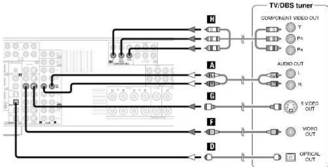
flowchart
graph TD
    A["Input Module"] --> B["Component A"]
    A --> C["Component B"]
    A --> D["Component C"]
    A --> E["Component D"]
    B --> F["Output Y"]
    B --> G["Output P3"]
    B --> H["Output P4"]
    C --> I["Output L"]
    C --> J["Output R"]
    D --> K["Output 8 VIDEO OUT"]
    D --> L["Output VIDEO OUT"]
    E --> M["Output OPTICAL OUT"]
Connecting a video camera or video game
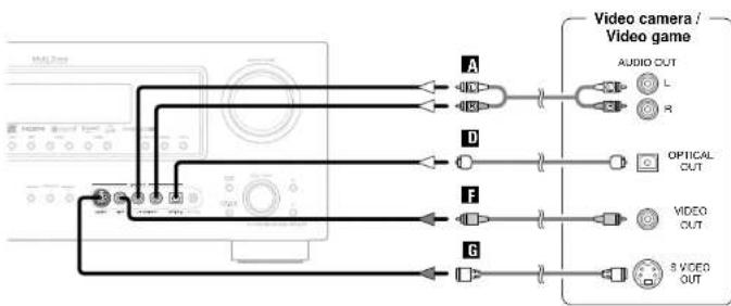
flowchart
graph TD
    A["Audio OUT"] --> B["O"]
    A --> C["IN"]
    D["Optical OUT"] --> E["D"]
    D --> F["F"]
    G["Video OUT"] --> H["G"]
    G --> I["3 VIGED OUT"]
Connecting Other Sources Connecting Other Sources
Connecting a CD player
To connect the digital audio output from the CD player, you can choose from either the coaxial or optical connections. If you choose to use the optical connection, it needs to be assigned. For more information about Digital Input Assignment (page 49).
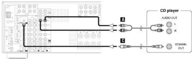
flowchart
graph LR
    A["CD player"] --> B["AUDIO OUT L"]
    A --> C["R"]
    A --> D["CAC/AXIAL OUT"]
Connecting a turntable
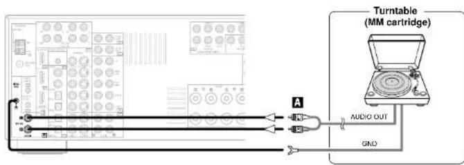

- The phono input can accept signals from moving magnet IMMI and high output moving coil (IMCI) phono cartridges. If your turntable is equipped with a low output MC cartridge, you will need to use a separate MC head amplifier or step-up MC transformer.
NOTE:
- If humming or other noise is generated when the ground wire is connected to the SIGNAL GND terminal, disconnect the ground wire.
ENGLISH
Connecting the external inputs (EXT. IN) terminals
- These terminals are for inputting multi-channel audio signals from an outboard decoder, or a component with a different type of multi-channel decoder, such as a DVD-Audio player, or a multi-channel Super Audio CD player, or other future multi-channel sound format decoder.
- The video signal connection is the same as that for a DVD player (page 9).
- For instructions on playback using the external input (EXT, IN) terminals (page 25).
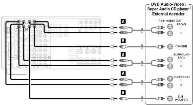
flowchart
graph TD
    A["Video Input"] --> B["7.10n AUDIO OUT"]
    B --> C["FRONT L n"]
    B --> D["CENTER"]
    B --> E["SURROUND BACK L n"]
    B --> F["SURROUND L n"]
    B --> G["SUB-WOOFER"]

- With discs on which special copyright protection measures have been taken, however, the digital signals may not be output from the DVD player. In this case, connect the DVD player's analog multi-channel output to the AVR-887's EXT. IN terminals for playback. Also refer to your DVD player's operating instructions.
ENGLISH
Connecting Other Sources Connecting Other Sources
Connecting equipment with HDMI terminals
- A simple 1-cable connection (using a commercially available cable) with a device having an HDMI (High-Definition Multimedia Interface) terminal allows digital transfer of the digital images of DVD-Video and other sources, and the multi-channel sound of DVD-Audio and DVD-Video.
- To provide audio output from AVR-887's audio output terminal, select "Amp" at the "HDMI In Assign". To provide audio output from the TV, select "TV" at the "HDMI In Assign" (page 53).
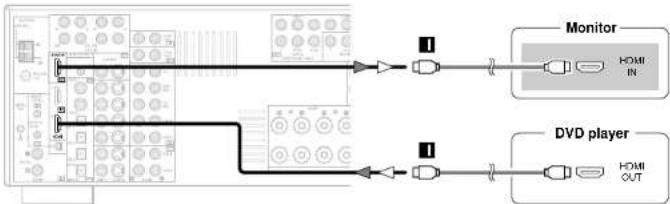
The AVR-887 is HDMI Ver. 1.1 compatible.
□ Copyright Protection System
To play back the digital video and audio of DVD-Video and DVD-Audio through an HDMI/DVI-D connection, both the connected player and monitor are required to support a copyright protection system called HDCP (High-bandwidth Digital Content Protection System). HDCP is copy protection technology that comprises data encryption and authentication of the partner equipment.
The AVR-887 supports HDCP. Please see the user's manual of your video display for more information about this.

- If your digital monitor or DVD player only supports DVLD, please obtain and use an HDMI-DVI conversion cable or adaptor, available from your dealer.
NOTE:
- The audio signals on the multi/stereo area of Super Audio CDs are not output. If the Super Audio CD is a hybrid CD, only the audio signals in the CD area are output.
- Use a compatible player to play DVD-Audio discs that are copyright protected by CPPM.
- Among the devices that support HDMI, some devices can control other devices via the HDMI terminal; however, the AVR-887 cannot be controlled by another device via the HDMI terminal.
- The audio signals from the HDMI terminal (including the sampling frequency and bit length) may be limited by the equipment that is connected.
- The video signals are not output properly if a device not compatible with HDCP is used.
- Use an HDMI monitor compatible with an HDMI input resolution of 480i or 576i.
- The video signals input from the HDMI input terminals are output to the HDMI monitor with their original resolution, so the image will not be displayed if the resolutions of the input signal and the monitor being used are not matched. In this case, change the setting of the resolution on the source device (player) to one which the monitor can handle.
- Use a cable including the HDMI logo (HDMI certified product) for connection of the HDMI terminal. Normal playback may not be possible if a cable that does not include the HDMI logo (non-HDMI-certified product) is used.
□ Connections with an HDMI/DVI-D conversion cable (adapter)
- The HDMI video stream signals [video signals] are theoretically compatible with DVI-D. When connecting to a monitor, etc., equipped with DVI-D terminals, it is possible to connect using an HDMI/DVI-D conversion cable, but depending on the combination of devices used the image might not be output.
- When using an HDMI/DVI-D conversion adapter, the image may not be output properly due to poor contact with the connected cable, etc.
Connecting Other Sources Connecting Other Sources
Connecting a DVD recorder
- For best picture quality choose the component video connection to your DVD recorder. S-Video and composite video outputs are also provided. If you choose to use the optical connection, it needs to be assigned. For more information about Digital Input Assignment (page 49).
- If you wish to perform analog dubbing from a digital sources, such as a DVD recorder to an analog recorder such as a cassette deck, you will needs connect the analog inputs and outputs as shown below, in addition to the digital audio connections.
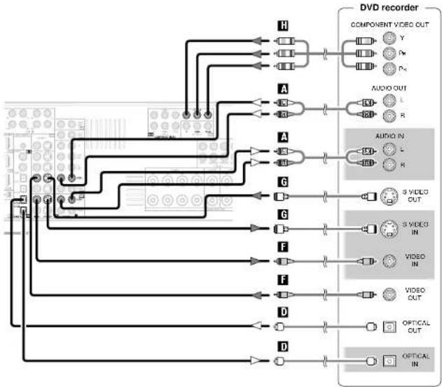
flowchart
graph TD
    A["Input Channel"] --> B["Component Video Out"]
    B --> C["Audio OUT"]
    C --> D["Audio IN"]
    D --> E["S VIDEO CUT"]
    E --> F["Video IN"]
    F --> G["Video OUT"]
    G --> H["Optical OUT"]
    H --> I["Optical IN"]
    style A fill:#f9f,stroke:#333
    style B fill:#ccf,stroke:#333
    style C fill:#cfc,stroke:#333
    style D fill:#fcc,stroke:#333
    style E fill:#cff,stroke:#333
    style F fill:#ffc,stroke:#333
    style G fill:#cfc,stroke:#333
    style H fill:#fcc,stroke:#333
    style I fill:#ffc,stroke:#333

- When recording to a DVD recorder, it is necessary that the type of cable used with the playback source equipment be the same type that is connected to the AVR-887 VCR-1 (to 2) OUTPUT terminal.
Example: TV IN → S-Video cable : VCR-1 OUT → S-Video cable TV IN → Video cable : VCR-1 OUT → Video cable
- The source selected for MAIN ZONE is output from the digital output terminal (OPT-3). The source selected in the REC SELECT mode is not associated with the output from the digital output terminal (OPT-3).
NOTE:
- Do not connect the output of the component connected to the OPTICAL 3 OUT terminal on the AVR-887's rear panel to any terminal other than the OPTICAL 3 IN terminal.
Connecting a VCR
- There are two sets of video deck (VCR) terminals, so two video decks can be connected for simultaneous recording or video copying.
- If you choose to use the component video connection, it needs to be assigned. For more information about Component Input Assignment (Page 53).
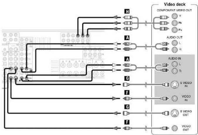
flowchart
graph TD
    A["Component"] --> B["Video deck"]
    B --> C["Component OUT"]
    C --> D["X"]
    C --> E["Y"]
    C --> F["Pb"]
    C --> G["R"]
    D --> H["A"]
    E --> I["A"]
    F --> J["A"]
    G --> K["A"]
    H --> L["A"]
    I --> M["A"]
    J --> N["A"]
    K --> O["A"]
    L --> P["AUDIO IN"]
    M --> Q["AUDIO IN"]
    N --> R["AUDIO IN"]
    O --> S["AUDIO IN"]
    P --> T["S VIDEO IN"]
    Q --> U["S VIDEO IN"]
    R --> V["S VIDEO OUT"]
    S --> W["S VIDEO OUT"]
    T --> X["S VIDEO OUT"]
    U --> Y["S VIDEO OUT"]

- When recording to a VCR, it is necessary that the type of cable used with the playback source equipment be the same type that is connected to the AVR-887 VCR-1 (to 2) OUT terminal.
Example: VCR-1 IN → S-Video cable : VCR-2 OUT → S-Video cable VCR-2 IN → Video cable : VCR-1 OUT → Video cable
ENGLISH
ENGLISH
Connecting Other Sources Connecting Other Sources
Connecting a tape deck, CD recorder or MD recorder
- If you wish to perform analog dubbing from a digital source, such as a CD or MD recorder to an analog recorder such as a tape deck, you will need to connect the analog inputs and outputs as shown below, in addition to the digital audio connections.
- If you choose to use the coaxial connection, it needs to be assigned. For more information about Digital Input Assignment I page 491.
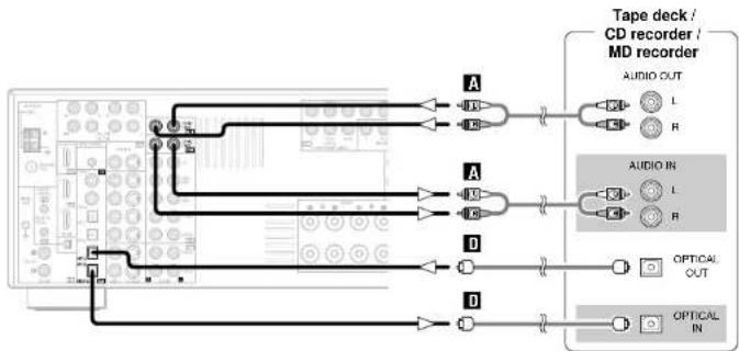
flowchart
graph TD
    A["CD/MD recorder"] -->|A| B["Audio OUT"]
    A -->|A| C["Audio IN"]
    A -->|D| D["Optical OUT"]
    A -->|D| E["Optical IN"]

- The source selected for MAIN ZONE is output from the digital output terminal (OPT-3). The source selected in the REC SELECT mode is not associated with the output from the digital output terminal (OPT-3).
NOTE:
- Do not connect the output of the component connected to the OPTICAL 3 OUT terminal on the AVR-887's rear panel to any terminal other than the OPTICAL 3 IN terminal.
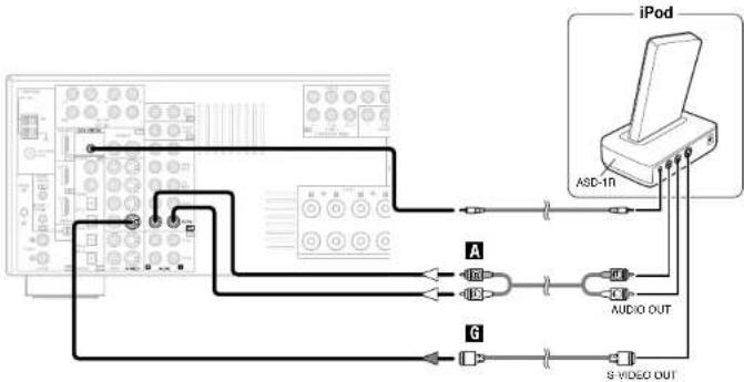
Connecting the iPod®
When using an iPod, you must connect the Control Dock for iPod (ASD-1R, sold separately) and the DOCK CONTROL jack on the AVR-887 with a mini-jack and assign the iPod to any AUDIO and/or S-VIDEO terminals. The diagram below shows an example of connections for when the iPod is assigned to the VCR-2 terminal.
For instructions on assigning the iPod to a specific terminal, see "Setting the iPod Assignment" (page 50).
* For instructions on playing the iPod, see "Playing the iPod" (page 40).
flowchart
graph TD
    A["Audio OUT"] --> B["A"]
    B --> C["1Hz"]
    B --> D["1.5V"]
    B --> E["Ground"]
    F["iPod"] --> G["A&D-1n"]
    G --> H["Audio OUT"]
    H --> I["S VIDEO OUT"]
    I --> J["Ground"]
    style A fill:#f9f,stroke:#333
    style F fill:#ccf,stroke:#333
    style G fill:#cfc,stroke:#333
    style H fill:#fcc,stroke:#333
    style I fill:#cff,stroke:#333

- The optional standard Control Dock for iPod is DENON ASD-1R sold separately.
Connecting Other Sources Connecting Other Sources
Connecting the antenna terminals
An F-type FM antenna cable plug can be connected directly.
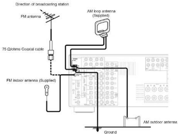
□ AM loop antenna assembly
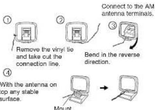
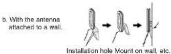
Connection of AM antennas

↓

↓

-
Push the lover.
-
Insert the conductor.
-
Return the lever.
NOTE:
- Do not connect two FM antennas simultaneously.
- Even if an external AM antenna is used, do not disconnect the AM loop antenna.
• Make sure the AM loop antenna lead terminals do not touch metal parts of the panel.
Note to CATV system installer:
This reminder is provided to call the CATV system installer's attention to Article B20-40 of the NEC which provides guidelines for proper grounding and, in particular, specifies that the cable ground shall be connected to the grounding system of the building, as close to the point of cable entry as practical.
Connecting the XM terminal
- A VR-887 is the XM Ready® receiver. You can receive XM® Satellite Radio by connecting to the XM Passport System (sold separately) and subscribing to the XM service.
- Plug the XM Passport System into XM terminal on the rear panel.
- Position the XM Passport System near a south-facing window to receive the best signal. For details, see "XM Satellite Radio" (Figure 38, 391).
When making connections, also refer to the operating instructions of the XM Passport System.
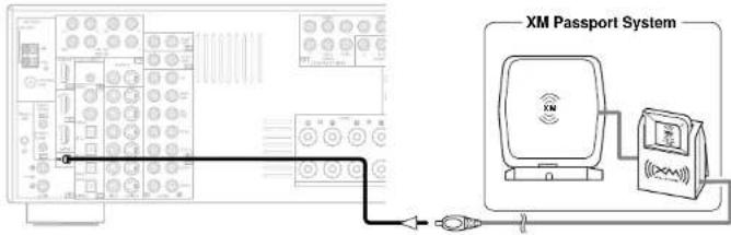
NOTE:
- Keep the power supply cord unplugged until the XM Passport System connection has been completed.
- The XM name and related logo are registered trademarks of XM Satellite Radio Inc. All rights reserved.
- XM Ready is a registered trademark of XM Satellite Radio Inc. All rights reserved.
ENGLISH
ENGLISH
Connecting Other Sources Connecting Other Sources
Connecting the MULTI ZONE terminals
For instructions on operations using the MULTI ZONE functions (page 42 \~ 44).
ZONE2 out connections
- When the power amplifier is assigned to the ZONE2 output channel at "Power Amp Assignment" in the "System Setup Menu", the surround back pre-out terminals can be used as the ZONE2 pre-out terminals (page 58).
- If another power amplifier or pre-main (integrated) amplifier is connected, the ZONE2 out (variable level) terminals can be used to play a different program source in ZONE2 the same time (page 42).
- When a sold separately room-to-room remote control unit (DENON RC-616, 617 or 618) is wired and connected between the MAIN ZONE and ZONE2, the remote-controllable devices in the MAIN ZONE can be controlled from ZONE2 using the remote control unit.
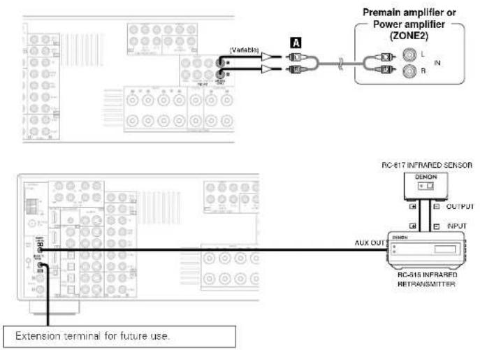
NOTE:
- For instructions on installation and operation of separately sold devices, refer to the devices' operating instructions.
ZONE2 speaker out connections
- When the power amplifier is assigned to the ZONE2 output channel at "Power Amp Assignment" in the "System Setup Menu", the surround back speaker terminals can be used as the ZONE2 speaker out terminals (page 58).
- The connections diagram below is an example for when the surround back speaker is assigned to the ZONE2 stereo 2 channel.
In this case, surround back speaker out can not be used for MAIN ZONE.
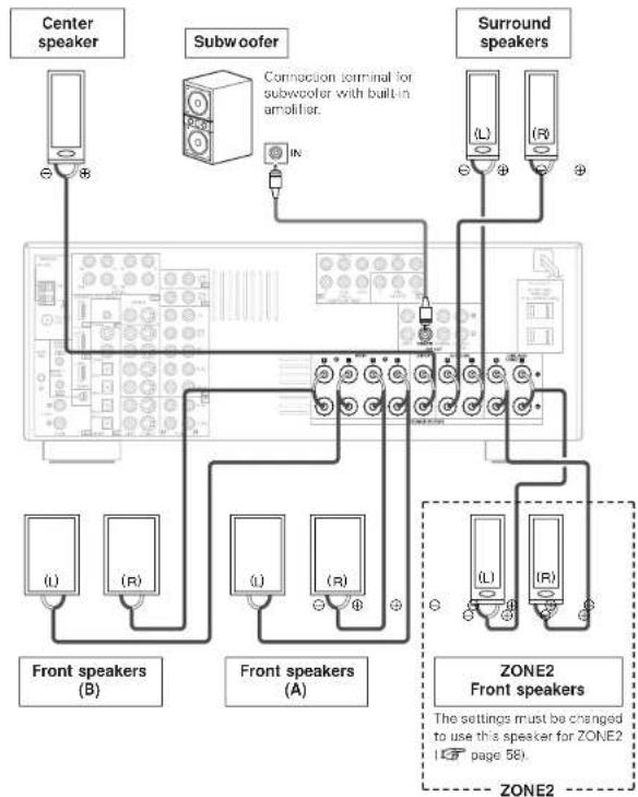
flowchart
graph TD
    A["Center speaker"] --> B["Subwoofer"]
    B --> C["Connection terminal for subwoofer with built-in amplifier."]
    D["Surround speakers"] --> E["Front speakers (A)"]
    D --> F["Front speakers (B)"]
    D --> G["Front speakers (C)"]
    H["ZONE2 Front speakers"] --> I["Front speakers (A)"]
    H --> J["Front speakers (B)"]
    K["Zone2"] --> L["Front speakers (A)"]
    K --> M["Front speakers (B)"]
    N["Ground"] --> O["Ground"]
Connecting Other Sources Connecting Other Sources
Connecting the PRE OUT terminals
- Use these terminals if you wish to connect external power amplifier(s) to increase the power of the front, center, surround and surround back sound channels, or for connection to powered loudspeakers.
- When using only one surround back speaker, connect it to the left channel.
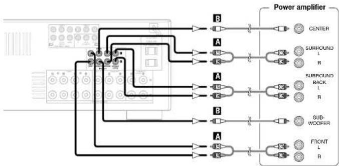
flowchart
graph TD
    A["Central Module"] --> B1["Power Amplifier"]
    A --> B2["Power Amplifier"]
    A --> B3["Power Amplifier"]
    A --> B4["Power Amplifier"]
    A --> B5["Power Amplifier"]
    B1 --> C1["CENTER"]
    B2 --> C2["SURROUND L R"]
    B3 --> C3["SURROUND BACK L R"]
    B4 --> C4["SUB-WOOFER"]
    B5 --> C5["FRONT L R"]
Connecting the power supply cord
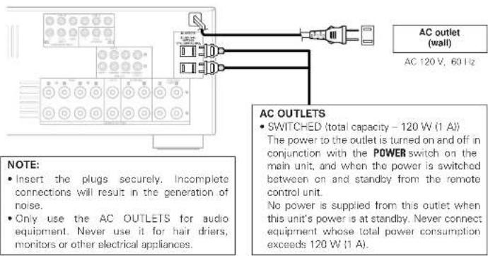
ENGLISH
ENGLISH
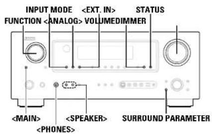
![FUNCTION VOLUME [MUTING] [ON SCREEN] DIMMER STATUS FUNCTION SURROUND PARAMETER INPUT MODE](/content/2026/05/817266/images/f4e0e872cb4b96ee2bff078420fc01cc8e270b7f73962ea3515e7c3930170f50.jpg)
![About the button names in this explanation < > : Buttons on the main unit [ ] : Buttons on the remote control unit Button name only : Buttons on the main unit and remote control unit](/content/2026/05/817266/images/252e14ea0c191366e9ad14f29b917089ea58f9ae9486ffc731841c661151b900.jpg)
Basic Operation
Playing the input source
1 Use FUNCTION to select the input source you want to play.
* To select the input source when ZONE2/REC SELECT is selected, press
2 Press INPUT MODE.
• The input mode indicator lights.
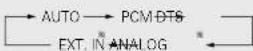
* Press
AUTO (All auto model:
The type of input signal is detected and the AVR-88/7's surround mode is switched automatically. Can be selected for sources for which the "Digital In Assignment" (137 page 49) is made. The mode switches automatically to DTS / Dolby Digital / PCM. The input switches to the analog input terminals is no digital signals are being input.
PCM (exclusive PCM signal playback mode) and
DTS (exclusive DTS signal playback mode):
Played when the various signals are input. Noise may be generated when a mode different from the input signal is set.
ANALOG (exclusive analog audio signal playback model) and
EXT. IN (External decoder input terminal selection mode): The signals input to the various input terminals are played.
* To lower the subwoofer channel level in the EXT. IN mode, press SURROUND PARAMETER and select "SW. ATT". For some players the playback level of the SW channel may seen strong. If so, set to "ON".
3 Start playback on the selected component.
* For operating instructions, refer to the component's manual.
4 Use VOLUME to adjust the volume.
• The volume level is displayed on the master volume level display.
* The volume can be adjusted between the range of -80 - 0 - 18 dB. Depending on the channel level settings and the different surround mode settings and when in the down-mix mode, it may not be possible to adjust the volume to 18 dB.

- Canceling the EXT. IN mode:
Press INPUT MODE or
- To use the EXT. IN mode together with a picture, select the input source to which the video signal is connected first, then set the input mode. - The "DIGITAL" indicator lights when digital signals are being input properly. If the "DIGITAL" indicator does not light, check whether the "Digital In Assignment" (page 49) and connections are correct.
NOTE:
- When the input mode is set to the external input (EXT, IN), the surround mode cannot be set.
- In play modes other than the external input mode, the signals connected to these terminals cannot be played.
Cautions when playing DTS sources:
- For DTS sources, be sure to connect the device to the digital input terminal and set "AUTO" or "DTS" for the input source. Noise will be generated if you play in the "ANALOG" or "PCM" mode.
- When playing DTS signals in the "AUTO" mode, noise may be generated when you first start playing and during searching. If so, play in the "DTS" mode.
Basic Operation Basic Operation
Turning the sound off temporarily (MUTING)
Press [MUTING].
※ You can adjust the muting level (range 58).
![DENON RC-1043 - Press [MUTING]. - 1](/content/2026/05/817266/images/16ea274b55582b622be0c79c3cc43203dd9efa23d863eca74b2177f2f4abe5c4.jpg)
- Canceling MUTING mode
To cancel the muting mode, either press [MUTING] or adjust the volume.
Listening over headphones
Connect the headphones to .
- No sound is produced from the speakers automatically.
NOTE:
- To prevent hearing loss, be careful not to raise the volume level excessively when using headphones.
Switching the front speakers
Press
Checking the currently playing program source, etc.

On screen display
Press [ON SCREEN].
- The current program source and various settings are displayed on the monitor screen.
![DENON RC-1043 - Press [ON SCREEN]. - 1](/content/2026/05/817266/images/9f7bf3f4cf55e396c50db5f7d3d8ed74e730a319688d5e2d06c49584aab2675e.jpg)
Front panel display
Press STATUS.
- The current program source and various settings are indicated on the display.
Switching the brightness of the display
Press DIMMER.
The brightness of the display can be adjusted in three steps. The display can also be turned off.
Using the surround modes
Types of surround modes and their features
The AVR-887 is equipped with many surround modes. We recommend using the surround modes as described below in order to achieve the maximum effect for the specific signal source.

☐ is a 6.1-channel/7.1-channel surround mode.
Sources recorded in Dolby Digital EX
DOLBY DIGITAL EX / +PLIIx*
(page 28)
- This mode is optimized for playing sources recorded in Dolby Digital EX.
Sources recorded in DTS-ES
DTS-ES DSCRT 6.1 / MTRX 6.1, +PLIIx*
(Page 28)
- This is the optimum mode for playing sources recorded in DTS-ES.
Dolby Digital or DTS Surround (5.1 ch sources)
2 ch sources recorded in Dolby Surround
DOLBY DIGITAL / DOLBY DIGITAL+PLIIx ^4
DTS SURROUND / DTS 96/24 / DTS+PLIIx ^™
DTS+NEO:6 (page 28)
- This mode is optimized for playing 5.1-channel or 7.1-channel music.
- For Dolby Surround recording sources, Dolby Pro Logic II playback is conducted.
2-channel sources recorded in XM HD Surround
NEURAL SURROUND (page 30)
[NO TEXT]
- This is the optimum mode for playing sources recorded in XM HD Surround.
ENGLISH
ENGLISH
Basic Operation Basic Operation
Sources recorded in stereo Sources recorded in monaural
PURE DIRECT
- Use this mode to play analog input music sources with extremely high quality.
DIRECT / STEREO
• Effective for achieving pure playback.
- If there is no need for tone control or distribution of the low frequencies in function of the speaker configuration, select the DIRECT mode to achieve the best sound quality.
DENON Original Surround Modes (page 35)
- Select these for 7.1-channel playback with sources recorded in stereo or monaural.
- The effects are different for each of the surround modes. Select the one most suited for the source being used.
DTS NEO:6 | page 30)
- This is a surround mode for playing 6.1- or 7.1-channel stereo sources developed by Digital Theater Systems.
• One of two playing modes, MUSIC (for music sources) or CINEMA (for movie sources), can be selected according to your preferences.
- Developed by Dolby Laboratories, this surround mode provides 7.1-channel surround sound with conventional stereo (2-channel) sources.
- Select CINEMA mode for movie surround soundtracks, MUSIC for music sources, and GAME for 2-channel game box audio sources.

- Surround modes marked with an asterisk (*) cannot be used when the surround back speaker is set to "NONE".
- The "+PLIIx Cinema" mode cannot be selected when only one surround back speaker is being used.
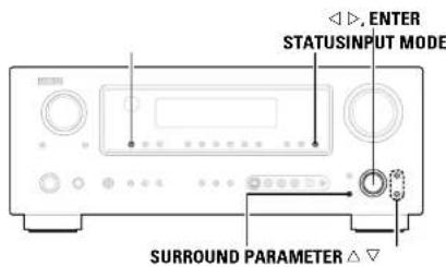
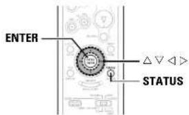
![[PURE DIRECT] [DIRECT/STEREO] ENTER [STANDARD] SURROUND PARAMETER INPUT MODE](/content/2026/05/817266/images/910f972882c1f95b5141dd822b687c710046d49f68f933bbd73d26fee6001e43.jpg)
About the button names in this explanation
< > : Buttons on the main unit
[ ] : Buttons on the remote control unit
Button name only
Buttons on the main unit and remote control unit
Selecting the play mode
(PURE DIRECT/DIRECT/STEREO)
The AVR-887 is equipped with three 2-channel playback modes exclusively for music. Select the mode to suit your tastes.
□ PURE DIRECT mode
This mode reproduces the sound with extremely high quality. The audio signals do not pass through the tone circuits, etc., and the display and surrounding circuits that could affect the audio signals are turned "OFF".
Press [PURE DIRECT].
□ DIRECT mode
This mode is for playing with high quality sound. The audio signals are transmitted directly, without passing through the tone circuits, etc.
Press [DIRECT/STEREO] to select "DIRECT".
STEREO DIRECT
□ STEREO mode
Use this mode to adjust the tone and achieve the desired sound.
Press [DIRECT/STEREO] to select "STEREO".
![DENON RC-1043 - Press [DIRECT/STEREO] to select "STEREO". - 1](/content/2026/05/817266/images/c0219be8373d9d9439df03380048ff78a3212dfc2a834501e34a44c280d1848c.jpg)
- The system setup function cannot be used when the PURE DIRECT mode is set. To use the system setup function, cancel the PURE DIRECT mode.
- If the HDMI input terminal is selected, video outputs are output in the PURE DIRECT mode.
- The channel level and surround parameters in the PURE DIRECT mode are the same as in the DIRECT mode.
Basic Operation Basic Operation
Selecting the Dolby Digital and DTS Surround mode (only with digital input)
1 Select an input source for which digital (COAXIAL, OPTICAL etc.) is set (page 49).
2 Press INPUT MODE to select "AUTO".
3 Press [STANDARD] to select "STANDARD (Dolby/DTS Surround)".
4 Play a program source with the mark
• " DIGITALC lights, also ending on the source.
5 Press SURROUND PARAMETER.
6 Press △△ to select the item, then press ◀◀ to set.
CINEMA EQ.:
Use this if movie dialogues sound harsh to lower the treble sound.
* Effective source mode
Dolby Pro Logic IIx / Dolby Pro Logic / Dolby Digital /
DTS Surround / DTS NEO:6
D.COMP.
The dynamic range is compressed. Select one of four modes: "OFF",
"LOW", "MID" (middle) or "HIGH".
* Effective source mode
Dolby Digital /
DTS (For DTS sources, only displayed for compatible software.)
LFE:
To play the various types of software properly, we recommend
setting to the values shown below.
• To play Dolby Digital software: "0 dB"
• To play DTS movie software: "0 dB"
• To play DTS music software: "-10 dB"
TONE:
Adjust the tone control.
※ Can be set in surround modes other than direct mode.
Can be set separately for the different surround modes. (Adjusted together for the Dolby/DTS SURROUND modes.)
Room EQ:
Sets the equalizer individually for each surround mode.
• Normal, Front, Flat:
See page 63
- Manual:
See page 57
SB CH OUT
Select the play mode or surround back channel playback method.
• The "SB-1SB" in SBator lights.
(1) For multi-channel sources
• SB OFF (OFF):
Not played.
• NON MTRX:
Surround channel signal played.
• MTRX ON:
Surround channel signal played with digital matrix processing
- ES MTRX:
DTS signal played with digital matrix processing.
• ES DSCRT:
Signal included in DTS-ES discrete 6.1-channel sources played.
• PLIX CINEMA:
Decoded in Dolby Pro Logic IIx Cinema mode, surround back signal played.
* Set the surround back speaker to "2spkrs" at "Speaker Configuration" (page 60).
• PLIIx MUSIC:
Decoded in Dolby Pro Logic Tx Music mode, surround back signal played
※ Set the surround back speaker to "1spkr" or "2spkrs" at "Speaker Configuration" (page 60).
(2) For 2-channel sources
• OFF: Not played.
• ON: Surround channel signal played.
7 Press ENTER or SURROUND PARAMETER.
![DENON RC-1043 - Press [DIRECT/STEREO] to select "STEREO". - 2](/content/2026/05/817266/images/e4d8adfc536d0a0bfa653c8b93728708496891a3868727bb7dac96f121911c81.jpg)
Example: Dolby Digital
Example: DTS
![DENON RC-1043 - Press [DIRECT/STEREO] to select "STEREO". - 3](/content/2026/05/817266/images/7726735ddbdf7a96ac144341847203d7e04e2aa5299823ab009238c9800ebc41.jpg)
- Select "Default Yes" and press< to reset all the settings.
☐ Dialog normalization function
This operates automatically when playing Dolby Digital sources. This is a function for automatically correcting the standard signal level for different program sources. The correction value can be checked by pressing STATUS.
![DENON RC-1043 - Press [DIRECT/STEREO] to select "STEREO". - 4](/content/2026/05/817266/images/678f293778caedc26b41acab136326fc9720d84bbecd114b4765c52835777633.jpg)
The numbers are the correction value when corrected to the standard level
ENGLISH
Basic Operation Basic Operation
![SURROUND PARAMETER ENTER [ON SCREEN] ENTER [STANDARD] SURROUND PARAMETER ENTER](/content/2026/05/817266/images/f4844416a2f1a8d97411d8875a2e430725b89a3e229172b35e4145c267e2817b.jpg)
About the button names in this explanation
< > : Buttons on the main unit
[ ] : Buttons on the remote control unit
Button name only :
Buttons on the main unit and remote control unit
Selecting the Dolby Pro Logic IIx (Pro Logic II) mode
It is possible to play analog input signals and digital input signals (2-channels) in the surround mode.
This mode is optimal for playing program sources recorded in Dolby Surround.
1 Press [STANDARD] to select "DOLBY PLIIx".
![DENON RC-1043 - Press [STANDARD] to select "DOLBY PLIIx". - 1](/content/2026/05/817266/images/889d02e30e37b818c25bf221aafe3dbaab6ff2a11210c856f03c411e3d50d1fb.jpg)
2 Play a program source.
3 Press SURROUND PARAMETER.
4 Press ◀◀ to select the play mode.
CINEMA:
This mode is suited for playing movie sources recorded in Dolby Surround and general sources recorded in stereo.
MUSIC:
This mode is suited for playing stereo music signals in the surround mode. With music signals, the sound field expansion differs according to the type of music, the recording conditions (live/studio), etc.. Because of this, the MUSIC mode offers a number of optional parameters for further adjusting the sound field.
GAME:
This mode is optimum for games. The GAME mode can only be used for 2-channel audio sources.
PL:
This mode is compatible with conventional Dolby Pro Logic sources.
* Optional parameters can only be set in the MUSIC mode. Select "OPTIONS", then press <1>
Press ENTER to return to the previous screen.
5 Press △△ to select the item, then press ◀◀ to set.
When "MUSIC" mode is selected:
PANORAMA:
This is effective when the surround effect seems weak
DIMENSION:
This shifts the center of the sound field image to the front or surround side. This compensates for when the sound field image seems unbalanced. (0 to 6, default: 3)
CENTER WIDTH:
A natural expansion to the front can be achieved by adjusting the center signal's output balance between the center and front channels. (0 to 7, default: 3)
6 Press ENTER or SURROUND PARAMETER.
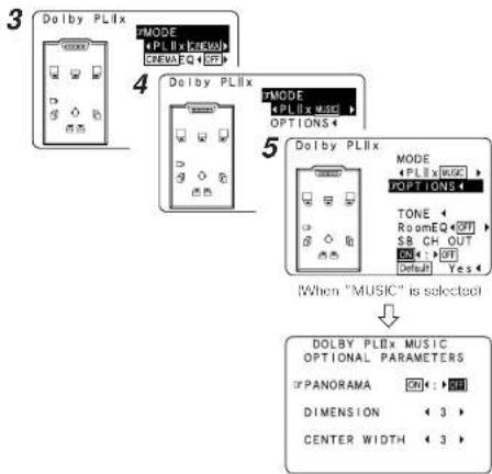
flowchart
graph TD
    A["3 Dolby PLix"] --> B["4 MODE"]
    B --> C["5 MODE"]
    C --> D["When "MUSIC" is selected"]
    D --> E["DOLBY PLix MUSIC OPTIONAL PARAMETERS"]
    E --> F["DOLBY PLix MUSIC OPTIONAL PARAMETERS"]
    style A fill:#f9f,stroke:#333
    style B fill:#ccf,stroke:#333
    style C fill:#cfc,stroke:#333
    style D fill:#fcc,stroke:#333
    style E fill:#cff,stroke:#333
(When "OPTIONS" is selected)
Basic Operation Basic Operation
Selecting the DTS NEO:6 mode
It is possible to play analog input signals and digital input signals (2-channels) in the surround mode.
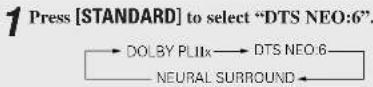
2 Play a program source.
3 Press SURROUND PARAMETER.
4 Press ◀◀ to select the play mode.
CINEMA:
This mode is optimum for playing movies. Decoding is performed with emphasis on separation performance to achieve the same atmosphere with 2-channel sources as with 6.1-channel sources.
MUSIC:
This mode is suited mainly for playing music.
5 Press △△ to select the item, then press ◀◀ to set.
When "MUSIC" mode is selected:
CNTR. IMAGE:
The expansion of the center channel can be adjusted. (0.0 to 1.0, default: 0.3)
6 Press ENTER or SURROUND PARAMETER.
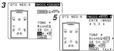
(When "MUSIC" is selected)
Selecting the NEURAL SURROUND mode
It is possible to play analog input signals and digital input signals (2-channels) in the surround mode.
This is the optimum mode for playing sources recorded in XM HD Surround (range 38, 39).

2 Play a program source.
3 Press SURROUND PARAMETER.
4 Press △△ to select the item, then press ◀◀ to set.
5 Press ENTER or SURROUND PARAMETER.
Checking the input signals
1 Press [ON SCREEN].
Room EQ:
Displays the type of equalizer currently set
SIGNAL
Displays the type of input signal.
fs:
Displays the input signal's sampling frequency.
FORMAT:
Displays the input signal's number of channels (front / surround / LFE on/off). "SURROUND" is displayed for 2-channel signal sources recorded in Dolby Surround.
ENGLISH
OFFSET:
Displays the dialog normalization offset value.
FLAG:
"MATRIX" is displayed if the input signal has undergone matrix processing, "DISCRETE" is displayed if the input signal has undergone discrete processing.
2 Press [ON SCREEN] again.
* OSD-1 : Input signal
OSD-2 : HDMI monitor information
OSD-3 : Input/output settings
OSD-4: Auto surround mode
OSD-5\~7:USER MODE 1\~3
OSD-8 \~ 14 ; Tuner preset stations
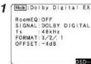
Example: Dolby Digital
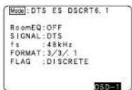
Example: DTS
The image is too blurry to recognize any text content.
- "OSD-1"-FLAG" is not displayed if there is no FLAG identification signal in the input signal.
- OSD-2:
The monitor's resolution is displayed when an HDMI monitor is connected to the AVR-887. - OSD-4
This is displayed when the auto surround mode is set to "ON" (page 57) and the input mode is set to "AUTO". It is not displayed when the input mode is set to "ANALOG" or "EXT. IN".
ENGLISH
Basic Operation Basic Operation
Surround modes and parameters
| Surround Mode | Signals and adjustability in the different modes | |||||||||||||||||||||
| Channel output Parameter default values are shown in parentheses | ||||||||||||||||||||||
| FRONT L/R | CENTER | SURROUND L/R | SURROUND BACK L/R | SUB-WOFFER | D. COMP *1 | LFE *2 | Route EC | SELL OUT | TONE CONTROL | CINEMA EQ. MODE | ROOM SIZE | EFFECT LEVEL | Dolby Digital | DELAY TIME | SURWACOFFR ON/OFF | PRO LOGIC INT'L MUSIC MODE only | NEOG MUSIC MODE only | EXT. IN any | ||||
| PANOFAMA | DIMENSION | CENTER WIDTH | CENTER IMAGE | SW ATI | ||||||||||||||||||
| PURE DIRECT, DIRECT | ○○ | ×× | ×× | ×× | ○○○ | ○○(OFF) | ○○(dB) | ○○(OFF) | ×× | ×× | ×× | ×× | ×× | ×× | ○○(OFF) | ×× | ○○ | ×× | ×× | ×× | ×× | ×× |
| MULTI CH DIRECT | ○○ | ○○○ | ○○○ | ○○○ | ○○○ | ×× | ○○(dB) | ○○(OFF) | ○○ | ×× | ×× | ×× | ×× | ×× | ×× | ×× | ×× | ×× | ×× | ×× | ×× | ×× |
| STEREO | ○○ | ×× | ×× | ×× | ○○○ | ○○(OFF) | ○○(dB) | ○○(OFF) | ×× | ○○(dB) | ×× | ×× | ×× | ×× | ○○(OFF) | ×× | ×× | ×× | ×× | ×× | ×× | ×× |
| EXT. IN | ○○ | ○○○ | ○○○ | ○○○ | ○○○ | ×× | ×× | ×× | ×× | ×× | ×× | ×× | ×× | ×× | ×× | ×× | ×× | ×× | ×× | ×× | ×× | ○○ |
| MULTI CH IN | ○○ | ○○○ | ○○○ | ○○○ | ○○○ | ×× | ○○(dB) | ○○(OFF) | ○○ | ○○(dB) | ×× | ×× | ×× | ×× | ×× | ×× | ×× | ×× | ×× | ×× | ×× | ×× |
| COLDY PRO LOGIC IIe | ○○ | ○○○ | ○○○ | ○○○ | ○○○ | ○○(OFF) | ×× | ○○(OFF) | ○○ | ○○(dB) | ○○(NOTE 2) | ○○(INEMAN) | ×× | ×× | ○○(OFF) | ×× | ×× | ○○(OFF) | ○○(2) | ○○(2) | ×× | ×× |
| COLDY PRO LOGIC II | ○○ | ○○○ | ○○○ | ×× | ○○○ | ○○(OFF) | ×× | ○○(OFF) | ○○ | ○○(dB) | ○○(NOTE 3) | ○○(INEMAN) | ×× | ×× | ○○(OFF) | ×× | ×× | ○○(OFF) | ○○(2) | ○○(2) | ×× | ×× |
| CTS NEO G | ○○ | ○○○ | ○○○ | ○○○ | ○○○ | ○○(Off) | ×× | ○○(Off) | ○○ | ○○(dB) | ○○(NOTE 2) | ○○(INEMAN) | ×× | ×× | ○○(Off) | ×× | ×× | ×× | ×× | ×× | ○○(2) | ×× |
| COLDY DIGITAL | ○○ | ○○○ | ○○○ | ○○○ | ○○○ | ○○(Off) | ○○(dB) | ○○(Off) | ○○ | ○○(dB) | ○○(OFF) | ×× | ×× | ×× | ○○(Off) | ×× | ×× | ×× | ×× | ×× | ×× | ×× |
| CTS SURROUND | ○○ | ○○○ | ○○○ | ○○○ | ○○○ | ○○(Off) | ○○(dB) | ○○(Off) | ○○ | ○○(dB) | ○○(OFF) | ×× | ×× | ×× | ×× | ×× | ×× | ×× | ×× | ×× | ×× | ×× |
| MURAL SURROUND | ○○ | ○○○ | ○○○ | ○○○ | ×× | ×× | ○○(Off) | ○○(Off) | ○○ | ○○(dB) | ×× | ×× | ×× | ×× | ×× | ×× | ×× | ×× | ×× | ×× | ×× | ×× |
| SOLY/OUI STROO | ○○ | ○○○ | ○○○ | ○○○ | ○○○ | ○○(Off) | ○○(dB) | ○○(Off) | ○○ | ○○(dB) | ×× | ×× | ×× | ×× | ○○(Off) | ×× | ×× | ×× | ×× | ×× | ×× | ×× |
| ROCK ARENA | ○○ | ○○○ | ○○○ | ○○○ | ○○○ | ○○(Off) | ○○(dB) | ○○(Off) | ○○ | ○○(NOTE 1) | ×× | ×× | ○(Medium) | ○○(Off) | ○○(Off) | ×× | ×× | ×× | ×× | ×× | ×× | ×× |
| JAZZ CLUB | ○○ | ○○○ | ○○○ | ○○○ | ○○○ | ○○(Off) | ○○(dB) | ○○(Off) | ○○ | ○○(dB) | ×× | ×× | ○(Medium) | ○○(Off) | ○○(Off) | ×× | ×× | ×× | ×× | ×× | ×× | ×× |
| MONO MOVE | ○○ | ○○○ | ○○○ | ○○○ | ○○○ | ○○(Off) | ○○(dB) | ○○(Off) | ○○ | ○○(dB) | ×× | ×× | ○(Medium) | ○○(Off) | ○○(Off) | ×× | ×× | ×× | ×× | ×× | ×× | ×× |
| VIDEO GAME | ○○ | ○○○ | ○○○ | ○○○ | ○○○ | ○○(Off) | ○○(dB) | ○○(Off) | ○○ | ○○(dB) | ×× | ×× | ○(Medium) | ○○(Off) | ○○(Off) | ×× | ×× | ×× | ×× | ×× | ×× | ×× |
| MATRIX | ○○ | ○○○ | ○○○ | ○○○ | ○○○ | ○○(Off) | ○○(dB) | ○○(Off) | ○○ | ○○(dB) | ×× | ×× | ×× | ×× | ○○(Off) | ○○(Off) msct | ×× | ×× | ×× | ×× | ×× | ×× |
| VIRTUAL | ○○ | ×× | ×× | ×× | ○○○ | ○○(Off) | ○○(dB) | ○○(Off) | ×× | ○○(dB) | ×× | ×× | ×× | ×× | ○○(Off) | ×× | ×× | ×× | ×× | ×× | ×× | ×× |
COSigna
No signal
Turned on or off by speaker
configuration setting
○○ Adjustable
XX Not adjustable
NOTE 1. BASS +6 dB, TREBLE +4 dB
NOTE 2: This parameter is available when the "MODE" is set to "CINEMA".
NOTE 3. This parameter is available when the "MODE" is set to "CINEMA" or "PL"
^37 : When playing Dolby Digital and DTS signals.
*2. When playing Dolby Digital, DTS, DVD Audio and Super Audio CD.
COSignal
×No signal
○○Adjustable
XX Not adjustable
Basic Operation Basic Operation
☐ Differences in surround mode names depending on the input signals
| Button | Note | Input signals | ||||||||||||||
| Surround Mode | ANALOG LINEAR PCM | DTS DOLBY DIGITAL | DVD AUDIO | |||||||||||||
| DTS ES DSCRT | DTS ES MTRX | DTS (5.1ch) | DTS 96/21 | COLBY DIGITAL EX | DOLEY DIGITAL EX | COLBY DIGITAL (5.1ch) | DOLEY DIGITAL (3,4,5ch) | COLBY DIGITAL (2ch) | DVD Audio (multi ch) | DVD Audio (2ch) | 176.4/192Hz | |||||
| STANDARD | ||||||||||||||||
| DTS SURROUND | ||||||||||||||||
| DTS ES DSCRT3.1 | *1 | XX | XX | ● | XX | XX | XX | XX | XX | XX | XX | XX | XX | XX | ||
| DTS ES MTRXE.1 | *1 | XX | XX | XX | ● | XX | XX | XX | XX | XX | XX | XX | XX | XX | ||
| DTS SURROUND | XX | XX | OO | OO | ● | XX | XX | XX | XX | XX | XX | XX | XX | |||
| DTS 86/24 | XX | XX | XX | XX | XX | ● | XX | XX | XX | XX | XX | XX | XX | |||
| DTS + PLIX CINEMA | *2 | XX | XX | OO | OO | OO | OO | XX | XX | XX | XX | XX | XX | XX | ||
| DTS + PLIX MUSIC | *1 | XX | XX | OO | OO | OO | OO | XX | XX | XX | XX | XX | XX | XX | ||
| DTS + NTO.6 | *1 | XX | XX | XX | OO | OO | OO | XX | XX | XX | XX | XX | XX | XX | ||
| DTS NFO.B CINEMA | OO | OO | XX | XX | XX | XX | XX | XX | XX | OO | XX | OO | XX | |||
| DTS NFO.B MUSIC | OO | OO | XX | XX | XX | XX | XX | XX | XX | OO | XX | OO | XX | |||
| DOLBY SURROUND | ||||||||||||||||
| DOLBY DIGITAL EX | *1 | XX | XX | XX | XX | XX | XX | OO | OO | OO | OO | XX | XX | XX | ||
| DOLBY DIGITAL | XX | XX | XX | XX | XX | XX | OO | ● | ● | ● | XX | XX | XX | |||
| DOLBY DIGITAL+PLIX CINEMA | *2 | XX | XX | XX | XX | XX | XX | ● | OO | OO | OO | XX | XX | XX | ||
| DOLEY DIGITAL+PLIX MUSIC | *1 | XX | XX | XX | XX | XX | XX | OO | OO | OO | OO | XX | XX | XX | ||
| DOLEY PRO LOGIC IX CINEMA | OO | OO | XX | XX | XX | XX | XX | XX | XX | XX | ● | XX | OO | |||
| DOLEY PRO LOGIC IX MUSIC | OO | OO | XX | XX | XX | XX | XX | XX | XX | XX | OO | XX | OO | |||
| DOLEY PRO LOGIC IX GAME | OO | OO | XX | XX | XX | XX | XX | XX | XX | XX | OO | XX | OO | |||
| DOLEY PRO LOGIC IX CINEMA | OO | OO | XX | XX | XX | XX | XX | XX | XX | XX | OO | XX | OO | |||
| DOLEY PRO LOGIC II MUSIC | OO | OO | XX | XX | XX | XX | XX | XX | XX | XX | OO | XX | OO | |||
| DOLEY PRO LOGIC II GAME | OO | OO | XX | XX | XX | XX | XX | XX | XX | XX | OO | XX | OO | |||
| DOLEY PRO LOGIC | OO | OO | XX | XX | XX | XX | XX | XX | XX | XX | OO | XX | OO | |||
| NEURAL SURROUND | OO | OO | XX | XX | XX | XX | XX | XX | XX | XX | XX | XX | XX | |||
| MULTI CH IN | ||||||||||||||||
| MULTI CH IN | XX | XX | XX | XX | XX | XX | XX | XX | XX | XX | XX | ● | XX | XX | ||
| MULTI IN + PLIX CINEMA | *2 | XX | XX | XX | XX | XX | XX | XX | XX | XX | XX | XX | OO | XX | XX | |
| MULTI IN + PLIX MUSIC | *1 | XX | XX | XX | XX | XX | XX | XX | XX | XX | XX | XX | OO | XX | XX | |
● : Mode selectable in default status
○○Selectable mode
XX Non-selectable mode
NOTE :
*1: This mode is not available when the Surround Back speaker setup is set to "None".
*2: This mode is not available when the Surround Back speaker setup is set to "1spkr" or "None".
ENGLISH
ENGLISH
Basic Operation Basic Operation
| Button | Input signals | |||||||||||||
| Surround Mode | Note | ANALOG LINEAR PCM | DTS DOLBY DIGITAL | DVD-AUDIO | ||||||||||
| DTS ES DISCHT | DTS ES MTRX | DTS [5.1ch] | DTS 98/24 | COLBY DIGITAL EX | DOLEY DIGITAL EX | DOLBY DIGITAL [5.1ch] | DOLEY DIGITAL [3.4.5ch] | DOLBY DIGITAL [2ch] | DVD-Audio (multi-ch) | DVD-Audio (5ch) | 173.4/192Hz | |||
| DIRECT | ||||||||||||||
| DIRECT | ○○ | ○○ | ○○ | ○○ | ○○ | ○○ | ○○ | ○○ | ○○ | ○○ | ×× | ○○ | ○○ | |
| MULTI CH DIRECT | ×× | ×× | ×× | ×× | ×× | ×× | ×× | ×× | ×× | ×× | ○○ | ×× | ×× | |
| M DIRECT + PLIX CINEMA | *2 | ×× | ×× | ×× | ×× | ×× | ×× | ×× | ×× | ×× | ×× | ○○ | ×× | ×× |
| M DIRECT + PLIX MUSIC | *1 | ×× | ×× | ×× | ×× | ×× | ×× | ×× | ×× | ×× | ×× | ○○ | ×× | ×× |
| PURE DIRECT | ||||||||||||||
| PURE DIRECT | ○○ | ○○ | ○○ | ○○ | ○○ | ○○ | ○○ | ○○ | ○○ | ○○ | ×× | ○○ | ○○ | |
| MULTI CH PURE DIRECT | ×× | ×× | ×× | ×× | ×× | ×× | ×× | ×× | ×× | ×× | ○○ | ×× | ×× | |
| M PURE D + PLIX CINEMA | *2 | ×× | ×× | ×× | ×× | ×× | ×× | ×× | ×× | ×× | ×× | ○○ | ×× | ×× |
| M PURE D + PLIX MUSIC | *1 | ×× | ×× | ×× | ×× | ×× | ×× | ×× | ×× | ×× | ×× | ○○ | ×× | ×× |
| CSP SIMULATION | ||||||||||||||
| SCH/CH STEREO | *3 | ○○ | ○○ | ○○ | ○○ | ○○ | ○○ | ○○ | ○○ | ○○ | ○○ | ○○ | ×× | ×× |
| ROCK ARENA | ○○ | ○○ | ○○ | ○○ | ○○ | ○○ | ○○ | ○○ | ○○ | ○○ | ○○ | ×× | ×× | |
| JAZZ CLUB | ○○ | ○○ | ○○ | ○○ | ○○ | ○○ | ○○ | ○○ | ○○ | ○○ | ○○ | ×× | ×× | |
| MONO MOVIE | ○○ | ○○ | ○○ | ○○ | ○○ | ○○ | ○○ | ○○ | ○○ | ○○ | ○○ | ×× | ×× | |
| MOFFO GAME | ○○ | ○○ | ○○ | ○○ | ○○ | ○○ | ○○ | ○○ | ○○ | ○○ | ○○ | ×× | ×× | |
| MATRIX | ○○ | ○○ | ○○ | ○○ | ○○ | ○○ | ○○ | ○○ | ○○ | ○○ | ○○ | ×× | ×× | |
| WHITUAL | ○○ | ○○ | ○○ | ○○ | ○○ | ○○ | ○○ | ○○ | ○○ | ○○ | ○○ | ×× | ×× | |
| STEREO | ||||||||||||||
| STEREO | ● | ● | ○○ | ○○ | ○○ | ○○ | ○○ | ○○ | ○○ | ○○ | ○○ | ● | ● | |
● : Mode selectable in default status
○○Selectable mode
× Non-selectable mode
NOTE :
*1: This mode is not available when the Surround Back speaker setup is set to "None".
*2: This mode is not available when the Surround Back speaker setup is set to "1sokr" or "None".
*3: If the Surround Back speaker setup is set to "None", then "5CH STEREO" is displayed.
Basic Operation Basic Operation
Using the DENON original surround modes
The AVR-887 is equipped with a high performance digital signal processor (DSP) that uses digital signal processing to recreate sound fields artificially. One of seven surround modes can be selected according to the program source and parameters can be further adjusted to achieve even more realistic sound fields.
Types of surround modes and their features
| 5CH/7CH STEREO (NOTE 1) | This mode lets you enjoy stereo sound with seven speakers. The front L (R) channel signals are played from the surround and surround back L (R) channels and only the in-phase component of the L and R channels is played on the center channel. |
| ROCK ARENA | This mode recreates the atmosphere of a live concert in an arena. |
| JAZZ CLUB | This mode recreates the atmosphere of a live concert in a club with low ceilings, hard walls and the artist just in front of you. |
| MONO MOVIE (NOTE 2) | This mode recreates the atmosphere of an expansive sound field for movie sources recorded in monaural. |
| VIDEO GAME | This mode provides a rich sense of presence for video games. |
| MATRIX | This mode recreates music sources recorded in stereo with an enhanced sense of expansion. |
| VIRTUAL | This mode can be used to enjoy surround sound with only front speakers or when using headphones. |
NOTE 1: "5CH STEREO" is displayed when "SB CH OUT" is set to "OFF".
NOTE 2: When playing sources recorded in monaural, the sound will be one-sided if signals are only input to one channel (left or right), so input signals to both channels. If you have a source component with only one audio output (monophonic camcorder, etc.) obtain a "Y" adapter cable to split the mono output to two outputs, and connect to the L and R inputs.

- Depending on the program source being played, the effect may not be very noticeable. In this case, try other surround modes, without worrying about their names, to create a sound field suited to your tastes.
ENGLISH
Basic Operation Basic Operation
![, SURROUND PARAMETER [CH SELECT], ENTER [DSP SIMULATION] ENTER SURROUND PARAMETER](/content/2026/05/817266/images/9d50621c178f90e64fc6b0b16aa624187908dcc3656c9ebbc6352e45fcf131e4.jpg)
About the button names in this explanation
< > ; Buttons on the main unit
[ ] : Buttons on the remote control unit
Buttons on the main unit and remote control unit
Button name only
Selecting the DSP surround simulation
☐ To operate the surround mode and the surround parameters from the remote control unit
1 Press [DSP SIMULATION].
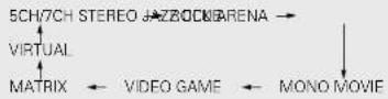
2 Press SURROUND PARAMETER.
3 Press △△ to select the item, then press ◀◀ to set.
SB CH OUT
• ON:
Surround back channel played.
• OFF:
Surround back channel not played.
ROOM SIZE:
Adjust the imaginary size of the recreated sound field space. (Does not express size of room in which played.)
There are five parameters: "small", "med.s", "medium", "med.l" and "large".
EFFECT LEVEL:
Adjust the strength of the surround effect.
DELAY TIME: (MATRIX mode only)
Adjust the delay time between "0 ms" and "110 ms".
4 Press ENTER or SURROUND PARAMETER.
2
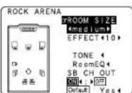

- Select "Default Yes" and press to reset all the settings.
☐ Operating the surround mode and the surround parameters from the main unit's panel
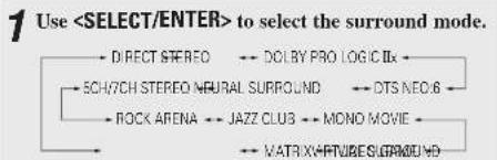
flowchart
graph TD
    A["DIRECT STEREO"] --> B["SCH/7CH STEREO NEURAL SURROUND"]
    B --> C["ROCK ARENA"] --> D["JAZZ CLUB"] --> E["MONO MOVIE"]
    E --> F["MATRIX CAPTURES SURROUND"]
    style A fill:#f9f,stroke:#333
    style B fill:#ccf,stroke:#333
    style C fill:#cfc,stroke:#333
    style D fill:#fcc,stroke:#333
    style E fill:#cff,stroke:#333
    style F fill:#ffc,stroke:#333
* To select the surround mode while adjusting the surround parameters, tone defeat or tone control, press
2 Perform steps 2 to 4 under "Selecting the DSPsurround simulation".
Basic Operation Basic Operation
Setting the tone control
Adjust the bass and treble to suit your tastes.
□ Adjusting the tone
1 Press SURROUND PARAMETER.
2 Press △△ to select "TONE", then press ◀.
※ In the direct mode, "TONE" cannot be selected
3 Press ▷ to select "OFF".
4 Press △△ to select "Bass" or "Treble", then press ◀◀◀ ▷to set the level.
* Can be adjusted within the range of -6 dB to +6 dB.
5 Press ENTER or SURROUND PARAMETER.
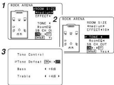
□ When you do not want to adjust the tone
Set "Tone Defeat" to "ON" at step 3 in "Adjusting the tone".
Adjusting the speaker volume
1 Press [CH SELECT].
2 Press △△ or [CH SELECT] to select the speaker.
※ The settable speaker switches each time this button is pressed.
3 Press [◀ ▷] to adjust the volume.
* The SW channel level can be turned off by decreasing it one step from -12.0 dB.
$$ \mathrm{OFF} \leftrightarrow - 1 2. 0 \mathrm{dB} \leftrightarrow + 1 2. 0 \mathrm{dB} $$
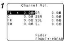

- "SB" when surround back speaker set to "1spkr". Not displayed when "None" set.
Using the fader function
With this function, the volume of all the front side speakers or all the rear side speakers can be adjusted (attenuated) at once.
1 Press [CH SELECT].
2 Press △ △ or[CH SELECT] to select "Fader".
3 Press [◀] to attenuate the volume of all the front side speakers, [▶] to attenuate the volume of all the rear side speakers.
* The fader function does not affect the subwoofer.
* It is possible to adjust so that the volume of the speaker whose volume is the lowest is -12.0 dB.
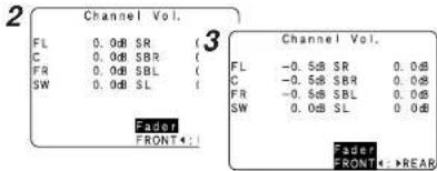
ENGLISH
Basic Operation Basic Operation
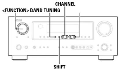
![SHIFT [FM/AM] CHANNEL [ON SCREEN]](/content/2026/05/817266/images/07f93c2da515924f138aa8a77d4dd1859b9b021f2f545f3ffa313e15e7de6782.jpg)
![[TUNER] TUNING [MODE] BAND [MEMORY]](/content/2026/05/817266/images/1303ff59ed447f8694c7ebc45f7acfbd82f4547b11f97b4c117d30240ea498fc.jpg)
About the button names in this explanation
< > : Buttons on the main unit
[ ] : Buttons on the remote control unit
Buttons on the main unit and remote control unit
Button name only
Listening to the radio
Check that the remote control unit is set to "AUDIO".
Auto tuning
1 Use
2 Press BAND to select "AM", "FM" or "XM".
* When listening to the XM Satellite Radio (page 38, 39).
3 Press [MODE] to set the auto tuning mode.
• The "AUTO" indicator lights
4 Press TUNING.
• Automatic searching begins.

- If tuning does not stop at the desired station, use to the "Manual tuning" operation.
- "AM" or "FM" can be selected directly by pressing [FM/AM].
Manual tuning
1 Use
2 Press BAND to select "AM", "FM" or "XM".
※ When listening to the XM Satellite Radio (page 38, 39).
3 Press [MODE] to set the manual tuning mode.
※ Check that the display's "AUTO" indicator turns off.
4 Press TUNING.
※ The frequency changes continuously when the button is held in.

- When the manual tuning mode is set, FM stereo broadcasts are received in monaural and the "STEREO" indicator turns off.
- "AM" or "FM" can be selected directly by pressing [FM/AM].
Basic Operation Basic Operation
Preset memory
1 Use the "Auto tuning" or "Manual tuning" operation to tune in the station to be preset in the memory.
2 Press [MEMORY].
3 Press SHIFT to select the desired memory block (A to G).
4 Press CHANNEL to select the desired preset channel (1 to 8).
5 Press [MEMORY] again.
• Store the station in the preset memory.

• To preset other channels, repeat steps 2 to 5.
A total of 56 broadcast stations can be preset — 8 stations (channels 1 to 8) in each of blocks A to C.
- The memory block can also be selected by pressing SHIFT.
Checking the preset stations
Press [ON SCREEN] repeatedly until the "Tuner Preset Stations" screen appears on the on screen display.
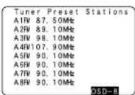
Recalling preset stations
1 Press SHIFT to select the memory block.
2 Press CHANNEL to select the desired preset channel.
XM Satellite Radio
AVR-B87 is the XM Ready receiver. You can receive XM® Satellite Radio by connecting to the XM Passport System (sold separately) and subscribing to the XM service.
□ Introducing XM Satellite Radio
There's a world of audio listening pleasure beyond AM and FM. XM Satellite Radio. Select from over 170 channels of music, news, sports, comedy, talk, and entertainment. Coast-to-coast coverage. Digital quality sound. With all music channels 100% commercial free. Questions?: Visit www.xmradio.com.
□ How to Subscribe
Listeners can subscribe by visiting XM on the Web at www.xmradio.com or by calling XM's Listener Care at (800) 967-2346. Customers should have their Radio ID and credit card ready. The Radio ID can be found by selecting channel 0 on the radio.
□ A Warning Against Reverse Engineering
It is prohibited to copy, decompile, disassemble, reverse engineer, or manipulate any technology incorporated in receivers compatible with the XM Satellite Radio system.
Furthermore, the AMBE® voice compression software included in this product is protected by intellectual property rights including patent rights, copyrights, and trade secrets of Digital Voice Systems, Inc. The user of this or any other software contained in an XM Radio is explicitly prohibited from attempting to copy, decompile, reverse engineer, or disassemble the object code, or in any other way convert the object code into human-readable form. The software is licensed solely for use within this product.
Hardware and required \$12.95 monthly service subscription sold separately. Other fees and taxes, including a one-time activation fee may apply. Subscription fee is consumer only. All fees and programming subject to change. Channels with frequent explicit language are indicated with an XL. Channel blocking is available for XM radio receivers by calling 1-800-XMRADIO. Subscriptions subject to Customer Agreement available at xmradio.com. XM service only available in the 48 contiguous United States. ©2006 XM Satellite Radio Inc. All rights reserved.
ENGLISH
ENGLISH
Basic Operation Basic Operation
![FUNCTION BAND TUNING STATUS VIDEO SELECT FUNCTION [XM RADIO] VIDEO SELECT [NIGHT] [△▽<▷] STATUS FUNCTION [TUNER] TUNING BAND [△▽<▷】](/content/2026/05/817266/images/6ca69a6591657d8363ad19c6d00d97ab26aed7531bf8695e9650bf1501c07cc4.jpg)
About the button names in this explanation
< > : Buttons on the main unit
[ ] : Buttons on the remote control unit
Button name only
Buttons on the main unit and remote control unit
Checking the XM signal strength and Radio ID
1 Use
2 Press BAND to select "XM".
3 Press STATUS until "SIGNAL" is displayed.
- The display changes as shown below according to the receiving condition.
| ConditionDisplay | |
| GOOD Signal strength is good | |
| MARGINAL Signal strength is marginal | |
| WEAK Signal strength is poor | |
| NO | Loss of the signal |
4 Adjust the antenna location until "SIGNAL:GOOD" is displayed.
5 Press STATUS until the XM channel (ex.XM001) is displayed.
6 Press TUNING to select channel 0 (XM000).

Channel selection
1 Use
2 Press BAND to select "XM".

3 Press TUNING to reach the desired channel.
※ The channel changes continuously when you press and hold TUNING. ※ When the artist name and song title are received, they are displayed.
Category search
1 Press [◀◀] in the XM mode. • The current category name is displayed.
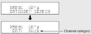
flowchart
graph TD
    A["CATEGORY SEARCH"] --> B["CMT"]
    B --> C["Channel category"]
2 Press [◀◀] to select the category, and press [△△] to select the channel within the selected category.

- "LOADING" is displayed while receiving the channel or information.
- "UPDATING" is displayed while updating encryption code.
- When the selected channel is not available, "XM - - -" is displayed.
- Information on the artist name, song title, category and signal level can be checked using STATUS.
- The XM Satellite Radio channels can be preset in the same way as AM/FM band I page 381.
- "XIV" can be selected directly by pressing [XM RADIO].
Advanced Operation
Night mode
The night mode can be set when playing Dolby Digital sources. The dialogues are easier to hear at night and when listening with the volume low.
Press [NIGHT].
![DENON RC-1043 - Press [NIGHT]. - 1](/content/2026/05/817266/images/fda11cac83d2286e0f5c7783cfce5be82f8f0ebbf3ba58f4a99b17729757c135.jpg)
![DENON RC-1043 - Press [NIGHT]. - 2](/content/2026/05/817266/images/88b1d2afdb1f790b18b0090b8dcececfff868f92f39a82f2b582d3dd3a14f650.jpg)
- Canceling night mode: Press [NIGHT] again.
- When the right mode is set to "ON", the "D.COMP" surround parameter can not be selected.
User mode function
The AVR-887 is equipped with a function for storing the selected input source, the auto surround mode and input mode in the memory and selecting these settings when you want to use them.
Storing the settings in the memory
1 The following are stored in the memory:
① Currently set input source
② Currently set surround mode
③Currently set input mode
2 Press
Calling the settings out
Press
Combining the currently playing sound with the desired image (VIDEO SELECT function)
Press VIDEO SELECT until the desired image appears on the monitor.

- To cancel, press VIDEO SELECT to select "SOURCE"
- The video source selected with the video select function is stored in the memory for the different input sources.
- It is not possible to select HDMI input signals:
- When playing HDMI video input signals, the analog video signal of another function cannot be selected for the HDMI video output.
Personal memory plus function
The surround mode last selected and the input mode setting are stored individually for the different input sources.
The surround parameters, tone control settings and playback level balance for the different output channels are memorized for each surround mode.
Playing the iPod®
The music recorded on the iPod can be played when using a Control Dock for iPod (ASD-1R, sold separately). The iPod can be controlled using the buttons on the main unit and the remote control unit.

iPod is a trademark of Apple Computer, Inc., registered in the U.S. and other countries.
* With the iPod, non-copyrighted contents and contents that may be legally reproduced or played may be reproduced and played by individuals for their personal use. Violating copyrights is prohibited by law.
1 Connect the AVR-887 and iPod using the Control Dock for iPod (ASD-1R) (page 21).
2 Assign the input terminal at "Setting the iPod Assignment" (page 50).
3 Use FUNCTION to select the function assigned in step 2.
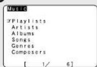
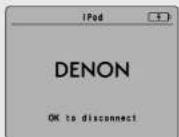
(iPod screen)
* If the screens above are not displayed, the iPod may not be properly connected. Check the connections and settings.

- The optional standard Control Dock for iPod is DENON ASD-1R sold separately.
NOTE:
- DENON will accept no responsibility whatsoever for loss or damage of data on an iPod occurring when the iPod is used connected to the AVR-887.
- Some of the functions may not operate, depending on the type of iPod and the software version.
ENGLISH
Advanced Operation Advanced Operation
![STATUSZONE2 [OFF] [ENTER] [VOLUME] [△▽◀▶] STATUS ZONE2 [MODE] [ENTER] [△▽◀▶] [MEMORY]](/content/2026/05/817266/images/e77ac0e974b4ee850bd26a94623744a3cc714c73ba1cb1a23d7fbf484ab3456f.jpg)
About the button names in this explanation
< > : Buttons on the main unit
[ ] : Buttons on the remote control unit
Button name only:
Buttons on the main unit and remote control unit
Listening to music
1 Press [△△] to select the music file, then press [ENTER] or [▷].
* Press [<] to return to the music menu screen.
2 Press [ENTER] or [▶]• Playback starts.
Pause:
Press [ENTER] during playback. Press again to resume.
Manual search:
Press and hold in [△△] during playback.
- △Fast reverse - ∨Fast forward
Track search:
Press [△△] during playback. • △Move to beginning of previous track • ∨Move to beginning of next track
Stop:
Press [ENTER] for at least 2 seconds during playback.
Repeat play:
Press [MODE]. The mode switches as follows each time [MODE] is pressed. • RPT One: Single track repeat • RPT All: All track repeat
Shuffle play:
Press [MEMORY]. The mode switches as follows each time [MEMORY] is pressed. SFL Songs: Single track shuffle SFL Albums: Album shuffle
※ The mode switches between the Browse mode and the Remote mode if [MODE] is pressed for at least 2 seconds. In the Remote mode, only [ ] and [ENTER] can be used.

- When STATUS is pressed during playback, the front panel display switches between the title name, print name and album name.
- Depending on the iPod's software version, it may not be possible to operate the iPod from the AVR-887. Use the latest version of the software. Information on the latest version of the software can be obtained on the Apple Computer website.
- If you do not want the on screen display to be displayed while playing the iPod, set "Function/Mode Status" at "Setting the On Screen Display" to "OFF" (page 55).
- With the AVR-887 it is possible to display folder names and file names on the screen like titles. The AVR-887 can display up to 64 characters, consisting of numbers, capital letters and small letters. A "?" mark is displayed in place of non-compatible characters.
Viewing still pictures and videos (only for iPods equipped with the slideshow / video function)
Use this procedure to view photo and video data stored on the iPod on a monitor.
Press [MODE] for at least 2 seconds to switch from the 1 Browse mode to the Remote mode.
- "Remote iPod" is displayed on the AVR-887's display.
Watching the iPod's screen, press [△] to select "Photos" or "Video", then press [ENTER] or [▷].
• The iPod's photo and video data are displayed on the monitor.

- To output photo or video data recorded on the iPod to the monitor, the iPod's "TV Out" setting (under "Video Settings") must be set to "ON".
For details, refer to the iPod's operating instructions.
Disconnecting the iPod
Press
* The iPod can be disconnected after switching to a function other than the one to which the iPod input is assigned.
Advanced Operation Advanced Operation
Multi zone music entertainment system
- When the outputs of the ZONE2 OUT terminals are wired and connected to integrated amplifiers installed in other rooms, different sources can be played in rooms other than the MAIN ZONE in which this unit and the playback devices are installed. (Refer to ZONE2 on the diagram below.)
- ZONE2 speaker out and pre-out can be used when "ZONE2" is selected at "Power Amp Assignment" in the "System Setup Menu". In this case, surround back speaker out cannot be used for MAIN ZONE.
- When a sold separately room-to-room remote control unit (DENON RC-616, 617 or 618) is wired and connected between the MAIN ZONE and ZONE2, the remote-controllable devices in the MAIN ZONE can be controlled from ZONE2 using the remote control unit.

- For the AUDIO outputs, use high quality pin-plug cables and wire in such a way that there is no humming or noise.
- For instructions on installation and operation of separately sold devices, refer to the devices' operating instructions.
- When the main unit is set to the recording output mode, ZONE2 remote control button cannot be operated.
☐ When using the SURR.BACK/ZONE2 amplifier as the ZONE2
- The SPEAKER OUT and PRE OUT terminals can be used simultaneously in ZONE2.
• To use the ZONE2, turn on ZONE2 - The output of the ZONE2 SPEAKER OUT terminals can be adjusted with [VOLUME] (ZONE2).
[System configuration and connections example 1]
Using this unit's internal amplifier as the ZONE2.
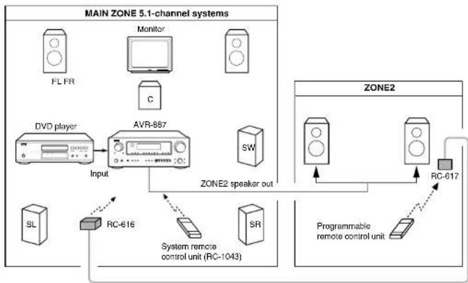
flowchart
graph TD
    subgraph MAIN ZONE 5.1-channel_systems
        A["FL FR"] --> B["DVD player"]
        C["Monitor"] --> D["AVR-887"]
        E["C"] --> D
        F["SL"] --> G["RC-616"]
        H["SR"] --> I["System remote control unit (RC-1043)"]
        J["SW"] --> K["Output"]
    end

    subgraph ZONE2
        L["Programmable remote control unit"] --> M["RC-617"]
        N["ZONE2 speaker out"] --> O["Output"]
    end

    M --> L
    M --> N
    style MAIN ZONE 5.1-channel_systems fill:#f9f9f9,stroke:#333
    style ZONE2 fill:#f9f9f9,stroke:#333
[System configuration and connections example 2]
Using external amplifier.
![DENON RC-1043 - [System configuration and connections example 2] - 1](/content/2026/05/817266/images/8f8897fdfdca4739d13688d32b3d836c7ad66ce9b4df1bfbfe37a70a86e730a3.jpg)
flowchart
graph TD
    subgraph MAIN ZONE 5.1-channel_systems["MAIN ZONE 5.1-channel systems"]
        A["FL FR"] --> B["DVD player"]
        C["Monitor"] --> D["AVR-867"]
        E["SL"] --> F["Input"]
        G["SW"] --> H["ZONE2 Audio out (Variable out)"]
        I["RC-616"] --> F
        J["SR"] --> F
        K["Programmable remote control unit"] --> L["RC-617"]
    end

    subgraph_ZONE2["ZONE2"]
        M["Radio Station"] --> N["Radio System"]
        O["Radio Station"] --> P["Radio System"]
        Q["Radio Station"] --> R["Radio System"]
        S["Radio Station"] --> T["Radio System"]
        U["Radio Station"] --> V["Radio System"]
        W["Radio Station"] --> X["Radio System"]
        Y["Radio Station"] --> Z["Radio System"]
        AA["Radio Station"] --> AB["Radio System"]
        AC["Radio Station"] --> AD["Radio System"]
        AE["Radio Station"] --> AF["Radio System"]
        AG["Radio Station"] --> AH["Radio System"]
        AI["Radio Station"] --> AJ["Radio System"]
        AK["Radio Station"] --> AL["Radio System"]
        AM["Radio Station"] --> AN["Radio System"]
        AO["Radio Station"] --> AP["Radio System"]
        AQ["Radio Station"] --> AR["Radio System"]
        AS["Radio Station"] --> AT["Radio System"]
        AU["Radio Station"] --> AV["Radio System"]
        AW["Radio Station"] --> AX["Radio System"]
        AY["Monitor"] --> AZ["Monitor"]
    end

    style MAIN ZONE 5.1-channel_systems fill:#f9f,stroke:#333
    style ZONE2 fill:#ccf,stroke:#333
Room-to-room remote control system (separately sold) control line
— : Multi source audio signal cable
—— : Speaker cable
* Refer to "Connections" (page 23).
ENGLISH
ENGLISH
Advanced Operation Advanced Operation
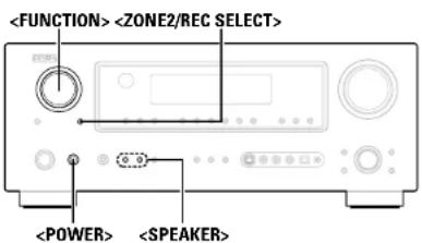
![[FUNCTION] [CHANNEL] [VOLUME] [MODE SELECTOR 1] [MODE SELECTOR 2] [ZONE2 OFF] [ZONE2 ON] [MAIN ON/OFF] [FUNCTION]](/content/2026/05/817266/images/cff5452cba904132e75919af0ccd7b5e156bc9380c93ddaf32942ca995029bb0.jpg)
About the button names in this explanation

Buttons on the main unit and remote control unit
Outputting a program source to amplifier, etc., in the ZONE2 room (ZONE2 SELECT mode)
1 Press
ZONE2 ←→ RECOUT
2 With "ZONE2 SOURCE" displayed, turn
- The "ZONE indicator and the indicator for the selected source light.
3 Start playing the source to be output.
* For operating instructions, refer to the manuals of the respective components.

- The signals of the source selected in the ZONE2 mode are also output from the VCR-1, VCR-2 and CD-R/TAPE recording output terminals.
• Digital signals are not output from the ZONE2 audio output terminals. - About the MULTI ZONE connections (page 42).
Remote control unit operations during multi-source playback
This is only possible when the main unit in the ZONE2 mode (58).
1 Set [MODE SELECTOR 1] to the "AUDIO".
2 Set [MODE SELECTOR 2] to the "ZONE2".
3 Press [ZONE2 ON].
• The "22 indicator lights.
* Tocancel the ZONE2 mode: Press [ZONE2 OFF].
4 Press [FUNCTION].
- The “ZONE” indicator and the indicator for the selected source light.
※ The ZONE2 source switches directly.
5 The output level of the ZONE2 SPEAKER OUT terminals can be controlled pressing [VOLUME].
※ Default setting (ZONE2 volume level): --- dB (Minimum)
6 When the ZONE2 SOURCE function is set to "TUNER", the preset channel can be selected pressing [CHANNEL].

- When using ZONE2, it is possible to turn the power for the MAIN ZONE only on or off by pressing [MAIN ON/OFF].
Advanced Operation Advanced Operation
Recording (audio and/or video)
1 Press
ZONE2 ←→ RECOUT
2 Use
- The "REC" indicator and the indicator for the selected source light.
3 Record (the audio or video signals).
* For operations, see the operating instructions of the device from which you are recording (audio or video signals).

- To cancel, press=ZONE2/REC SELECT> and set the function to "ZONE2".
- The source selected for MAIN ZONE is output from the digital output terminal (IOPT-3).
The source selected in the REC SELECT mode is not associated with the output from the digital output terminal (OPT-3).
NOTE:
- When the REC OUT mode is selected, [ZONE2] and [FUNCTION] (ZONE2) cannot be operated.
• Digital signals are not output from the analog REC OUT terminal.
About the memory functions
□ Last function memory
The various settings set when the AVR-887's power is switched to standby are stored in the memory. When the power is turned back on, the settings made when the power was switched to standby are recalled.
□ Backup memory
The various settings are stored in the memory for about 1 week, even when the power is turned off or the power cord is unplugged.
Initialization of the microprocessor (Reset)
Use the procedure described below to reset the microprocessor if the display is abnormal or if the buttons on the main unit or the remote control unit do not operate.
1 Switch off the unit using
2 Hold the following
3 Check that the entire display is blinking with an interval of about 1 second, and release your fingers from the 2 buttons.
• The microprocessor will be initialized.

- If step 3 does not work, start over from step 1
- If the microprocessor has been reset, all the settings are reset to the default values.
ENGLISH
Advanced Setup – Part 1
System setup items and default values
| PageDefault setting | ||||
| 1. Auto Setup/Room EQ or1. Auto Setup 2. Room EQ Setup 3. Direct Mode Setup 4. Parameter Check Exit | Auto Setup | The AVR-887 performs an analysis of the speaker system and measures the acoustic characteristics of your room to permit an appropriate automatic setting. | - | 10 ~ 13 |
| Room EQ Setup | Set the Room Equalizer setting with "All" or "Assign" for each surround mode. | All, Room EQ = OFF | 63 | |
| Direct Mode Setup | Set the ON/OFF setting of Room Equalizer, in the case of the surround mode is in "DIRECT" or "PURE DIRECT". | OFF | 64 | |
| PageDefault setting | |||||||||||||
| 1 | Speaker Configuration | Automatically set the output component and properties for the various channels according to the combination of speakers to be actually used for surround playback. | Front Sp. | Center Sp. Surround Sp.Subwoofer | Surround Back Sp. | 60 | |||||||
| Large | Small Small Yes | Small / 2spks | |||||||||||
| 2 | Subwoofer Setup | Select the method of playback of the subwoofer for playing the low bass signals. | LTC | 61 | |||||||||
| 3 | Distance | This parameter is for optimizing the timing with which the audio signals are produced from the speakers and subwoofer according to the listening position. | Front L & R | Center | Subwoofer | Surround L & R | Surround Back | 61 | |||||
| 10 ft [3.0 m]12 | 1 (3.0 ft)2D/dt18.5 m² 12 ft [3.5 m²] | ||||||||||||
| 4 | Channel Level | Set the volume of the various speakers so that the sound output from the speakers and the subwoofer seems to have the same volume level. | Front L | Front R | Center Sur | Surround NSL Subwoofer | Surround Back L | Surround Back R | 62 | ||||
| 0 dB 0 | dB 0 dB | 0 dB 0 dB | 0 dB | 0 dB 0 dB | |||||||||
| 5 | Crossover Frequency | Set the frequency (Hz) below which the bass sound of the various speakers is to be output from the subwoofer. | 80 Hz | 63 | |||||||||
Advanced Setup – Part 1 Advanced Setup – Part 1
- Audio Input Setup
| 3. Audio Input Setup or1. Digital In Assign 2. EXT, IN Subwoofer Level 3. iPod Assign 4. Input Function Lev. 5. Function Rename 6. Tuner Presets Exit | 1 | Digital In Assignment | This assigns the digital input terminals for the different input sources. | Input source | CO OVE / VDP IV / DOS VCH 1 | VCH 2 | COR / TAPE | V. AUX | 49 | |||
| Digital Inputs | COAX 1 | OPT 1 | OPT 2 | COAX 2 | OFF | OPT 3 | OPT 4 | |||||
| 2 | EXT. IN Subwoofer Level | Sets the playback level of the analog signal that was input to the EXT. IN subwoofer terminal. | SW Level = +15 dB | 50 | ||||||||
| 3 | IPod Assignment | It is possible to assign the Control Dock for iPod's (ASD-1R, sold separately) audio and/or video signals to any input terminals on the AVR-887 and play them. | iPod Function = OFF | 50 | ||||||||
| 4 | Input Function Level | The playback level is corrected individually for the different input sources. | PHONO COTUNER | COR / TAPE | CVO / VDP | TV / DNS | VCR-1 | VCR-2 | V. AUX | |||
| 0 dB 0 dB 0 dB 0 dB | 0 dB | 0 dB 0 dB 0 dB | ||||||||||
| 5 | Function Rename | The name of the input function that is displayed can be changed. | PHONO COTUNER | COR / TAPE | CVO / VDP | TV / DNS | VCH 1 | VCR 2 | V. AUX | |||
| 6 | Tuner Presets | Up to 56 FM stations can be preset automatically. | Auto Preset Memory | A1 - A8 | 87.5/69.1/38.1/107.3/50.1/30.1/30.1/50.1 MHz | 51 | ||||||
| B1 - B8 | 520/500/1000/1400/1500/1/10 kHz, 30.1/50.1 MHz | |||||||||||
| C1 - C8 | 90.1 MHz | |||||||||||
| D1 - D8 | 90.1 MHz | |||||||||||
| E1 - E8 | 90.1 MHz | |||||||||||
| G1 - G8 | 90.1 MHz | |||||||||||
| Preset channels that are not used often can be skipped. | Preset Skip | All press channels = ON | b2 | |||||||||
| The preset channels can be given the names you want. | Preset Name | 52 | ||||||||||
- Video Setup
| 4. Video Setup or1. HDMI In Assign 2. Component In Assign 3. Video Convert 4. HDMI Out Setup 5. Audio Delay 6. On Screen Display Exit | 1 | HDMI In Assignment | The HDMI input terminals are assigned for the different input sources. Select the HDMI audio signal play/ack method. | DVD / VDP | TV / DBS | VCR-1 | VCR-2 | V AUX | 53 |
| NONE | NONE | NONE | NONE | NONE | |||||
| 2 | Component In Assignment | This assigns the component video input terminals for the different input sources. | DVD / VDF | TV / DBS | VCR-1 | VCR-2 | V AUX | 53 | |
| 1-RCA | 2-RCA | 3-RCA | NONE | NONE | |||||
| 3 | V Ideo Convert | This sets whether or not to use the video conversion function. | ON | 54 | |||||
| 4 | HDMI Out Setup | Set whether or not to up convert from analog video signals to HDMI. When this function is used, the format of the signal output from the HDMI terminal can be set. | OFF | 54 | |||||
| Audio Delay5 | Adjust the time delay between the video and audio signals. | 0 ms | 55 | ||||||
| 6 | On Screen Display | Set whether or not to display the on screen display for indications other than the menu screens. | Function/Mode = CN Master Volume = ON Mode = Mode 1 | 55 | |||||
ENGLISH
fault setting
ENGLISH
Advanced Setup – Part 1 Advanced Setup – Part 1
- Advanced Playback
| 5. Advanced Playbackor1. 2ch Direct/Stereo2. Dolby Digital Setup3. Auto Surround Mode4. Manual EQ SetupExit | 1 | 2chDirect/ Stereo | Make the 2-channel direct mode and stereo mode speaker settings. | Basic | 56 |
| 2 | Dolby Digital Setup | Turn the audio compression on or off when down-mixing Dolby Digital signals. | OFF | 56 | |
| 3 | Auto Surround Mode | Set whether or not to store the surround mode last played for the input signal. | Auto Surround Mode = ON | 57 | |
| 4 | Manual EQ Setup | Adjust the tone of the various speakers while listening to the playback signals. | All Channels and Frequency = 0 dB | 57 |
- Option Setup
| 6. Option Setup1. Power Amp Assign2. Volume Control3. Setup Lock | 1 | Power Amp Assign | To suit your preference, a surround back channel's power amplifier can be assigned to the front channel ("Front A" or "Front B") for bi-amp playback, ZONE2. | S Back | 58 | |
| 2 | V olume Control | This sets the volume level of output. | Main | Vallimir - OFFF On Lev - LASTMate Lev - FUT | 58 | |
| 3 | Setup Lock | This sets whether or not to lock the system setup settings so that they cannot be changed. | Setup Lock - OIT | 59 | ||
Advanced Setup – Part 1 Advanced Setup – Part 1
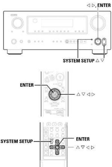
Use System Setup to customize a variety of settings to suit your listening environment. For the contents of a system menu and the initial setting of this unit (page 45 - 47).
Navigating through the System Setup Menu
![1 Press SYSTEM SETUP. • The "System Setup Menu" appears. 2 Press △△ to select the item you want to set, then press ENTER. 3 Press △△ again to select the item you want to set, then press ENTER. 4 Tochange the setting: Press △△ to select the item you want to change, then press < to change the setting. * Select "Default Yes", then press < to reset to the default setting. 5 Press ENTER and set a new item. 6 Press SYSTEM SETUP to return to the "System Setup Menu" or the main menu. [ On screen display ] [ Display ] System Setup Menu 1. Auto Setup/Room EQ 2. Speaker Setup 3. Audio Input Setup 4. Video Setup 3. Audio Input Setup #1. Digital In Assign 2. EXT. IN Subcofter Level 3. iPod Assign 4. Input Function Lev. 3-1. Digital In Assign #CE: COAX# DVD OPT1 TV OPT2 VCH COAX2 RCH OFF System Setup Menu 1. Auto Setup/Room EQ 2. Speaker Setup 3. Audio Input Setup 4. Video Setup 5. Advanced Playback 6. Option Setup #Exit #SYSTEM SETUP Audio In Setup *Audio In Setup Digital In +D Sital In CD: COAX1# *SYSTEM SETUP Exit](/content/2026/05/817266/images/f46d359ff6151b68c4862e130b3151c5c53cc3075c22d0e995262d67eb1c7e06.jpg)
![About the button names in this explanation < > : Buttons on the main unit [ ] : Buttons on the remote control unit Button name only : Buttons on the main unit and remote control unit](/content/2026/05/817266/images/7db130bd0c87aa78dccfa55971826c94923997740799f2c44bc3b08a6622a28b.jpg)
ENGLISH
ENGLISH
Advanced Setup – Part 1 Advanced Setup – Part 1
About the on screen display and front display
The AVR-887 is equipped with an intuitive and easy-to-understand on screen display, and is equipped with an alphanumeric front panel display that can also be used to check and adjust settings. We recommend that you use the on screen display when you make system adjustments. Some representative front display and on screen display examples are shown below.
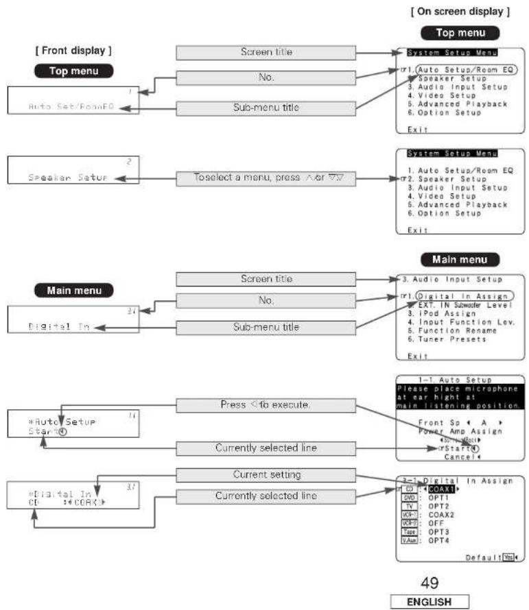
flowchart
graph TD
    A["Front display"] --> B["Top menu"]
    B --> C["Screen title"]
    C --> D["System Setup Menu"]
    D --> E["1. Auto Setup/Room EQ"]
    E --> F["Speaker Setup"]
    F --> G["Audio Input Setup"]
    G --> H["Video Setup"]
    H --> I["Advanced Playback"]
    I --> J["Option Setup"]
    J --> K["Exit"]
    L["Speaker Setup"] --> M["Toselect a menu, press /or //7"]
    M --> N["System Setup Menu"]
    N --> O["1. Auto Setup/Room EQ"]
    O --> P["Speaker Setup"]
    P --> Q["Audio Input Setup"]
    Q --> R["Video Setup"]
    R --> S["Advanced Playback"]
    S --> T["Option Setup"]
    T --> U["Exit"]
    V["Main menu"] --> W["Screen title"]
    W --> X["Main menu"]
    X --> Y["Digital In"]
    Y --> Z["21"]
    Z --> AA["Screen title"]
    AA --> AB["3. Audio Input Setup"]
    AB --> AC["Digital In Assign"]
    AC --> AD["EXT. IN Summerer Level"]
    AD --> AE["iPod Assign"]
    AE --> AF["Input Function Lev."]
    AF --> AG["Function Rename"]
    AG --> AH["6. Tuner Presets"]
    AH --> AI["Exit"]
    AJ["*Auto Setup Start@"] --> AK["Press Info execute"]
    AK --> AL["1-1 Auto Setup Please place microphone at ear hight at main listening position"]
    AL --> AM["Front Sp < A > Power Amp Assign"]
    AM --> AN["Current setting"]
    AN --> AO["*Digital In CE: *DCOR*"]
    AN --> AP["Currently selected line"]
    AP --> AQ["Current setting"]
    AQ --> AR["4-1 Digital In Assign"]
    AR --> AS["OPT1: COAX1"]
    AR --> AT["OPT2: OPT1"]
    AR --> AU["OPT2: OPT2"]
    AR --> AV["OPT3: COAX2"]
    AR --> AW["OPT4: OFF"]
    AR --> AX["V/Aux: OPT4"]
Audio Input Setup
Setting the Digital In Assignment
This assigns the digital input terminals for the different input sources.
1 Press △△ TO select "Audio Input Setup", then press ENTER.
2 Press △ △ ∨ to select "Digital In Assign", then press ENTER.
3 Press △ △ to select the input source, then press ◀ ◀ ◀ to set.
COAX1, COAX2, OPT1, OPT2, OPT3, OPT4:
Assign the different terminals according to the devices connected to the AVR-887's input terminals.
The HDMI input terminal is displayed when it is assigned to the input source at "HDMI In Assignment" (page 53).
4 Press ENTER.
![1 System Setup Menu 1. Auto Setup/Room EQ 2. Speaker Setup 3. Audio Input Setup 4. Video S 5. Advance 2 6. Option 1 Exit 2 3. Audio Input Setup UI. Digital In Assign 2. EXT, IN [Standard Level] 3. iPod As 4. Input F 5. Function 6. Tuner P Exit 3 3-1. Digital In Assign CD: COAX1 DVD OPT1 TV OPT2 GCM COAX2 GCS OFF Time OPT3 VAuto OPT4 Default[Base]](/content/2026/05/817266/images/aec8e7b5cd54e221cb92c4f8cf58949b6715419d91777e4babc50d3d3ea2801d.jpg)

- "PHONO" and "TUNER" cannot be selected on the "Digital In Assign" screen.
- It is not possible to make the "Digital In Assignment" settings for the function assigned at "iPod Assignment".
Advanced Setup – Part 1 Advanced Setup – Part 1
Setting the EXT. IN Subwoofer Level
Sets the playback level of the analog signal that was input to the EXT. IN subwoofer terminal.
1 Press △△ to select "EXT. IN Subwoofer Level", then press ENTER.
2 Press ◀◀ to set.
3 Press ENTER.
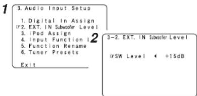
Setting the iPod Assignment
It is possible to assign the Control Dock for iPod's (ASD-1R, sold separately) audio and/or video signals to any input terminals on the AVR-887 and play them.
1 Press △△ to select "iPod Assign", then press ENTER.
2 Press ◀ ▷ to set.
OFF: This is the factory default setting.
CD, CDR/TAPE: When using a Control Dock for iPod, it is possible to connect with the audio input terminal of the assigned function.
DVD/VDP, TV/DBS, VCR-1, VCR-2, V. AUX: When using a Control Dock for iPod, it is possible to connect with the audio and video input terminals of the assigned function.
3 Press ENTER.
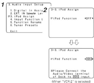
flowchart
graph TD
    A["3. Audio Input Setup\n1. Digital In Assign\n2. EXT. IN Subwoofer Len\n3. iPod Assign\n4. Input Function L\n5. Function Rename\n6. Tuner Presets\nExit"] --> B["3-3. iPod Assign\n@iPod Function OFF"]
    B --> C["3-3. iPod Assign\n@iPod Function VCR-2\n#Please Connect the Audio/Video terminal of Dock to VCR-2 input\n(When "VCR-2" is selected)"]
Setting the Input Function Level
The playback level is corrected individually for the different input sources.
1 Press △△ to select "Input Function Lev.", then press ENTER.
2 Press △△ ▽ to select the input source, then press ◀◀ ▶▶ to set.
※ The volume can be adjusted within the range -12 dB to +12 dB.
3 Press ENTER.
![1 3. Audio Input Setup 1. Digital In Assi 2 2. EXT. IN Subwoofer Lei 3. iPod Assign 4. Input Function 1 5. Function Rename 6. Tuner Presets Exit 3-4. Input Function Lev. Tuner 0dB VND-0: 0dB Phone 0dB VAA: 0dB CD 0dB Tape 0dB BVD 0dB Cap 0dB VCD-1 0dB Default[Bus]](/content/2026/05/817266/images/1bb303ba6451c6ed2d25e3964105aaa201fd53c717f86f586fdcc37d77cd4931.jpg)

- After completing this setting, check that the playback levels for the different sources are the same.
ENGLISH
ENGLISH
Advanced Setup – Part 1 Advanced Setup – Part 1
Setting the Function Rename
The name of the input function that is displayed can be changed.
1 Press △△ to select "Function Rename", then press ENTER.
2 Press △△ to select the input function, then press ◀◀ ▷ to set.
3 Press ◀◀▶to move the cursor (■) to the desired position, then press △△ ▽▼ to select the character.
※ Up to 8 characters can be input. The characters that can be input are shown below.
ABCDEFGHIJKLMNOPQRSTUVWXYZ abcdefghijklmnopqrstuvwxyz01234 56789 !" # % & ' ) * + , - . / ; ; <= > ? @ [ \ ] (space)
4 Repeat step 3 to input the input source name.
* To set the input function name back to how it was: ① Press <1> to highlight the input function name, then press △▽ ② Press △▽ to select "Default Yes", then press ◀
5 Once all the characters have been input, press ENTER.
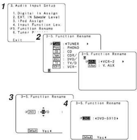
Setting the Tuner Presets
□ Auto Preset Memory
Up to 56 FM stations can be preset automatically
1 Press △ △ to select "Tuner Presets", then press ENTER.
2 Press △△ to select "Auto Preset Memory", then press ENTER.
2 Press ◀ to select "Yes".
- "Search" blinks on the screen and searching begins. - "Completed" appears once searching is completed.
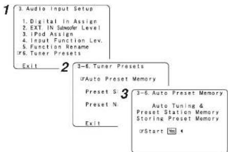

- If an FM station cannot be preset automatically due to poor reception, use the "Manual tuning" operation ( page 371 to tune in the station, then preset it using the manual "Preset memory" operation ( page 38).
Advanced Setup – Part 1 Advanced Setup – Part 1
□ Preset Skip
Preset channels that are not used often can be skipped.
1 Press △△ TO select "Preset Skip", then press ENTER.
2 Press △ △ ▽ to select the preset channel, then press ◀◀ ▶ to set.
ON.OFF
Select "OFF" to skip the preset channel, "ON" if you do not want to skip.
* When v is pressed at the very bottom of the screen, then the next preset memory block appears.
3 Press ◀◀ to select the preset memory block.
4 Repeat steps 2 and 3.
5 Press ENTER.
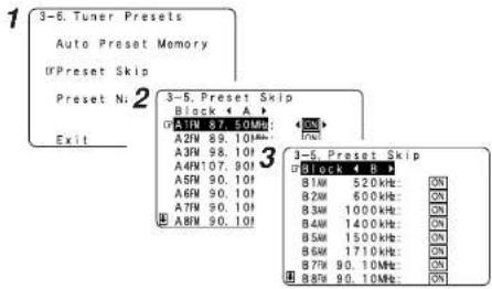
□ Preset Name
The preset channels can be given the names you want. (Except the XM channels.)
1 Press △ △ to select "Preset Name", then press ENTER.
2 Press △ △ to select the preset channel, then press ◀ to set.
3 Press ◀◀ to move the cursor( ■) to the desired position, then press △△ ▽to select the character.
* Up to 8 characters can be input.
The characters that can be input are shown below.
ABCDEFGHIJKLMNOPQRSTUVWXYZ abcdefghijklmnopqrstuvwxyz01234 56789 !" # % & ' ) . + , - . / : ; <= > ? @ [ \ ] (space)
4 Repeat step 3 to input the preset channel name.
※ To set the preset channel name back to how it was:
① Press ◀ highlight the preset channel, then press △ ∨.
② Press △▽ to select "Default Yes", then press ◀
5 Once all the characters have been input, press ENTER.
6 Press ENTER.
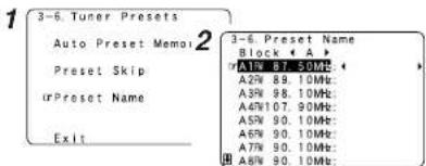
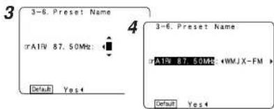
ENGLISH
Advanced Setup – Part 1 Advanced Setup – Part 1
Video Setup Setting the Component In Assignment
Setting the HDMI In Assignment
The HDMI input terminals are assigned for the different input sources. Select the HDMI audio signal playback method.
1 Press △△ to select "Video Setup", then press ENTER.
2 Press △△ ▽ to select "HDMI In Assign", then press ENTER.
3 Press △△ to select the input source, then press ◀◀ ▶▶ to set.
HDMI1, HDMI2:
Assign the "HDMI1" or "HDMI2" input terminal to the input function.
4 Press △△ to select "Audio", then press ◀◀ to select where to output the audio signals.
AMP:
Output the speakers connected to the AVR-B87.
TV:
Output the TV connected to the AVR-887.
5 If no audio signal is included in the input signal: Press △△ to select the input source, then press ◀◀▶▶ to set.
EXT. IN, ANALOG:
If there is no HDMI audio signal, the signal automatically switches to the input from the set terminal.
6 Press ENTER.


- If a monitor is connected with an HDMI cable but the monitor is not compatible with HDMI audio signal playback, only the video signals are output to the monitor from the AVR-B87.
- Audio signals input from the analog and digital terminals are not output to the TV.
- With HDMI, the video and audio signals are transferred simultaneously. When HDMI is assigned to an input source, the digital audio input assignment switches to HDMI along with the video input.
When this setting is made for input sources to which a digital audio input (COAXIAL or OPTICAL) is previously assigned, the digital audio assignment is set to HDMI.
In this case, reassign the digital input using the procedure described at "Digital In Assign" (Page 49). - It is not possible to make the "HDMI In Assignment" settings for the function assigned at "iPod Assignment".
This assigns the component video input terminals for the different input sources.
1 Press to select "Component In Assign", then press ENTER.
2 Press △△ ▽ to select the input source, then press ◀◀ ▶▶ to set.
- It is not possible to make the "Component In Assignment" settings for the function assigned at "iPod Assignment".
Advanced Setup – Part 1 Advanced Setup – Part 1
Setting the Video Convert
This sets whether or not to use the video conversion function.
1 Press △△ to select "Video Convert", then press ENTER.
2 Press △△ ∅ to select the input source, then press ◀◀ ▶▶ to set.
ON.OFF:
Select "ON" to use the video conversion function, "OFF" if you do not want to use it.
3 Press ENTER.
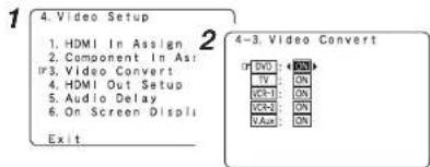

- If the resolution of the input component video signal is something other than 480/576, down-conversion from the component video signal to S-Video or video signals is not possible. If you do not want to use the component video output terminal, connect the player to the S-Video or video input terminal (Page 15, 16).
- When a non-standard video signal from a game machine or some other source is input, the video conversion function might not operate. If this happens, please set the conversion mode to "OFF".
- When the video conversion function has been used, information such as that of text broadcasts which has been added to the video signal might not be output. If this happens, please set the conversion mode to "OFF".
Setting the HDMI Out Setup
Set whether or not to up-convert from analog video signals to HDMI. When this function is used, the format of the signal output from the HDMI terminal can be set.
1 Press △△ ▽ to select "HDMI Out Setup", then press ENTER.
2 Press ◀ to select "ON".
3 Press △△ ▶to select the item, then press ◀◀ to set.
Analog to HDMI Convert:
• OFF
This is the factory default setting.
Setting for not converting analog video signals into HDMI signals.
• ON:
Setting for converting analog video signals into HDMI signals.
A monitor compatible with a resolution of 480i is required in order to use this function.
The on screen display signals of AVR-BB7 are output with a resolution of 480i.
Analog video signals are converted into digital video signals with the same resolution with which they were input and are then output from the HDMI terminal.
Example:
Analog signals input with a resolution of 480i are output from the HDMI terminal with a resolution of 480i.
Color Space:
• YCb Cr:
The YCb Cr format video signals is output via the HDMI output terminal.
• RGB
The RGB format video signals is output via the HDMI output terminal.
RGB Mode Setup:
• Normal:
Signals are output via the HDMI output terminal with a digital RGB video range (data range) of 16 (black) to 235 (white).
• Enhanced:
Signals are output via the HDMI output connector with a digital RGB video range (data range) of 0 (black) to 255 (white).
When the HDMI terminals are connected, the black may seem to stand out, depending on the TV or the monitor. In this case, set this to "Enhanced".
ENGLISH
4 Press ENTER.
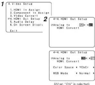

- When "Y Co Cr" is selected under "Color Space", "RGB Mode Setup" will have no effect.
- "Color Space" and "RGB Mode Setup" are only displayed when "Analog to HDMI Convert" is set to "ON".
- When connecting to an HDCP compatible monitor equipped with DVI-D terminal using an HDMI/DVI-D converter cable, the signals are output in RGB format, regardless of the "Color Space" setting.
- To view the on screen display using an HDMI monitor, set "Analog to HDMI Convert" at "HDMI Out Setup" to "ON" (default).
ENGLISH
Advanced Setup – Part 1 Advanced Setup – Part 1
Setting the Audio Delay
Adjust the time delay between the video and audio signals.
1 Press △△ to select "Audio Delay", then press ENTER.
2 Press ◁ ◁ to set.
0 ms \~ 200 ms:
Adjust the time delay.
※ With a movie source, for example, adjust so that the movement of the actors' lips is synchronized with the sound.
3 Press ENTER.
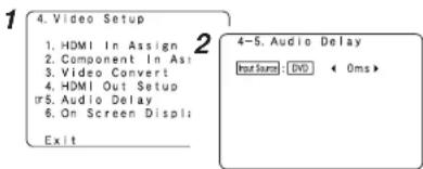

- By default, this menu is not displayed when no digital signals are being input.
- To make this setting for the component video signal, select the delay time and turn the on screen display off, then check that the timing of the component video and audio match.
- The audio delay setting does not apply when playing in the EXT. IN mode or in the analog input direct mode or stereo mode (Front speaker setting "Large", TONE DEFEAT "ON" and Room EQ "OFF").
Setting the On Screen Display (OSD)
Set whether or not to display the on screen display for indications other than the menu screens.
1 Press △△ ▽ to select "On Screen Display", then press ENTER.
2 Press △△ to select the item, then press ◀◀ to set.
Function/ Mode Status:
• ON, OFF:
Select "ON" to display the on screen display when the input source is selected, "OFF" if you do not want to display it.
Master Volume Status:
• ON, OFF:
Select "ON" to display the on screen display when the main volume is adjusted, "OFF" if you do not want to display it.
Display Mode:
- Mode1
Flickering is not prevented.
- Mode2:
Prevents flickering of the on screen display when there is no video signal.
Use this mode if the on screen display is not displayed in "Mode1".
3 Press ENTER.
1
-
Video Setup
-
HDMI In Assign
- Component In Assign
- Video Convert
- HDMI Out Satve
- Audio Delay
- On Screen Display
Exit
2
4-6. On Screen Display
Function/Mode Status

Master Volume Status

Display Mode
Mode1←:►Mode2
Advanced Setup – Part 1 Advanced Setup – Part 1
Advanced Playback
Setting the 2ch Direct/ Stereo
Make the 2-channel direct mode and stereo mode speaker settings.
1 Press △△ to select "Advanced Playback", then press ENTER.
2 Press △△ to select "2ch Direct / Stereo", then press ENTER. • The current settings are displayed.
3 Press ◀◀ [to] select "Basic" or "Custom".
Basic:
The "Speaker Setup" settings are displayed.
Custom:
The speaker settings for the 2-channel direct and stereo modes can be changed.
4 Press △△ ▽ to select the item, then press ◀◀ to set.
* For a description of the settings for the different items, see pages 60 \~ 63.
5 Press ENTER.
1
System Setup Menu
- Auto Setup/Room
- Speaker Setup
- Audio Input Setu
- Video Setup or 5. Advanced Playback
- Option Setup
Exit
5.
- Advanced Playback ir1. 2ch Direct/Stereo
- Dolby Digital Setup
- Auto Surround Mode
- Manual EQ Setup
Exit
3
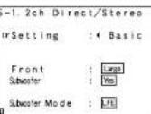
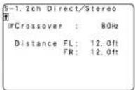
4
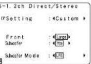
Setting the Dolby Digital Downmix Option Setup
Turn the audio compression on or off when down-mixing Dolby Digital signals.
1 Press △△ to select "Dolby Digital Setup", then press ENTER.
2 Press ◀◀◀ to set.
ON:
The dynamic range is compressed automatically according to the combination of speakers being used. Set "Compression" to "ON" if it seems that sound is distorted because the input level exceeds the allowable input for the front speakers.
OFF:
The dynamic range is not compressed. Normally using in this mode.
3 Press ENTER.
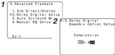

- When a center speaker or surround speakers are not connected, the sounds in those channels are directed to the front speakers.
ENGLISH
Advanced Setup – Part 1 Advanced Setup – Part 1
Setting the Auto Surround Mode
Set whether or not to store the surround mode last played for the input signal.
The surround mode used at last for the four types of input signals shown below is stored in the memory, and the signal is automatically played with that surround mode the next time it is input.
① Analog and PCM 2-channel signals (STEREO)
② 2-channel signals of Dolby Digital, DTS or other multi-channel format (DOLBY PLIIx Cinema)
③ Multi-channel signals of Dolby Digital, DTS or other multi-channel format (DOLBY/DTS SURROUND)
④ PCM multi-channel signals other than Dolby Digital and DTS (MULTI CH IN)
* Default settings are indicated in ( ).
* During playback in the PURE DIRECT mode, the surround mode does not change even if the input signal is changed.
1 Press △▽ to select "Auto Surround Mode", then press ENTER.
2 Press ◀◀ □to set.
3 Press ENTER.
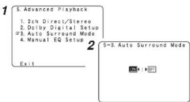
Setting the Manual Equalizer Setup
Adjust the tone of the various speakers while listening to the playback signals.
1 Press △△ ▽ to select "Manual EQ Setup", then press ENTER.
2 Press ◀◀ to set, then press ENTER.
All CH:
All channels can be adjusted simultaneously.
L/R CH:
The left and right channels of the pair of speakers can be adjusted simultaneously.
Each CH:
The channels can be adjusted separately.
3 Press ◀◀ to select the speaker.
※ The display changes as follows.
① Select "L/R CH"
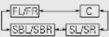
② Select "Each CH"
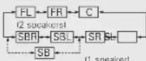
③ Select "All CH" In this case, speaker selection is not performed.
4 Press △△ to select the frequency, then press ◀◀ to adjust.
* The level of the various frequencies can be adjusted between -6.0 dB and +6.0 dB.
5 Press ENTER.
1 5. Advanced Playback
- 2ch Direct/Steri
- Dolby Digital Si
- Auto Surround M
- Manual EQ Setup
Ex | t
S-4. Manual EQ
Default Yes
orAdjust CH
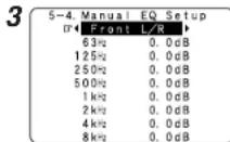
Advanced Setup – Part 1
Option Setup
Setting the Power Amplifier Assignment
To suit your preference, a surround back channel's power amplifier can be assigned to the front channel ("Front A" or "Front B") for bi-amp playback, ZONE2.
| Power Amplifier Assignment | SPEAKER OUT | PRE-OUT S.BACK/ZONE2 | |
| MAIN ZONE | ZONE2 | ||
| Surround Back 7.1 | 1ch system | - | Surround back |
| ZONE2 | 5.1ch system | 2ch system | ZONE2 |
| Bi-Amp 5.1ch system | - | - | |
1 Press △△ to select "Option Setup", then press ENTER.
2 Press △△ ▽to select "Power Amp Assign", then press ENTER.
3 Press ◀◀ □to set.
Surround Back:
The surround back speakers are used in MAIN ZONE.
Front A, Front B:
This provides a bi-amp mode for the two main front speakers, replicating the front A or front B amplifier channel's outputs.
ZONE2:
This mode assigns the surround back amplifier channels to provide ZONE2 speaker-level outputs from the surround back speaker terminals.
4 Press ENTER.
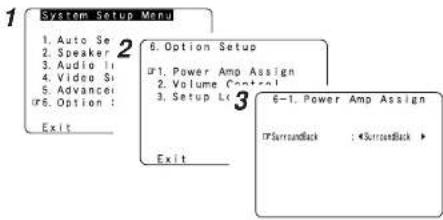
Front Bi-Amp connections
Dynamic sound with a range wider than that of full range systems can be played by connecting bi-amp compatible speakers to the AVR-887. Be sure to consult the owner's manual of your bi-amp-capable speakers for further information before proceeding.
![AVR-887 Speaker [R] Speaker [L]](/content/2026/05/817266/images/c3b7eb6bf4ae03ef6188d6a2a36b0b3f44baee41e3a57d02516c098d4f138de7.jpg)
NOTE:
- When making bi-amp connections, be sure to remove the short-circuiting bar included with the speaker.
ENGLISH
Advanced Setup – Part 1
Setting the Volume Control
This sets the volume level of output.
1 Press △△▽to select "Volume Control", then press ENTER.
2 Press △ △ to select the item, then press ◀◀ to set.
Volume Limit:
Set the volume's upper limit.
• OFF:
If you do not want to set a volume limit, select "OFF". In this case, the volume can be set to the AVR-887's maximum volume (output) level of +18 dB, which is extremely loud.
-20 dB, -10 dB, 0 dB:
The volume cannot be increased above the selected levels.
Power On Lev.:
Set the volume level when the power is turned on. You can adjust the MAIN ZONE volume level within the range of -80 to +18 dB (and ZONE2 volume level within the range of -70 to +18 dB).
LAST:
The volume set when the AVR-887 was last used is stored in the memory and set when the power is turned on.
- --- (Mute):
The volume is always muted when the power is turned on.
Mute Lev.:
Set the level of volume attenuation in the mute mode.
FULL:
The volume is fully muted.
-20 dB, -40 dB:
The volume is lowered 20 dB or 40 dB from the current level.
3 Press ENTER.
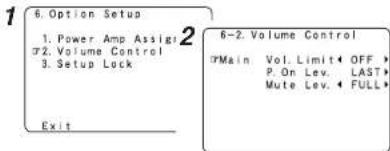
ENGLISH
Advanced Setup – Part 1 Advanced Setup – Part 1
Setting the Setup Lock
This sets whether or not to lock the system setup settings so that they cannot be changed.
1 Press △△ to select "Setup Lock", then press ENTER.
2 Press ◀ to select "ON", then press ENTER.
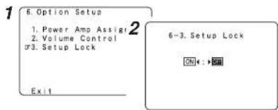

- When the setup lock function is activated, the settings listed below cannot be changed, and "SETUP LOCKED!" is displayed when related buttons are operated.
- System setup settings
• Surround parameter settings - Tone control settings
• Channel level settings (including test tones)
• Room EQ settings - To unlock, press SYSTEM SETUP again and display the "Setup Lock" screen, then select "OFF" and press ENTER.
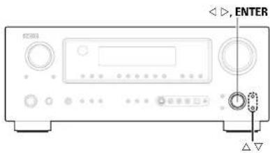
![ENTER [TEST TONE] ENTER Δ▽](/content/2026/05/817266/images/caf1146075af718eb649ac4cbb74f8fc1b4f6f427228d0ca86c3f289484fab12.jpg)
Advanced Setup – Part 2
Speaker Setup
- If the "Auto Setup" procedure has already been performed, there is no need to make this setting.
- Perform this setting if you wish to make the settings for your speaker systems manually.
Setting the Speaker Configuration
Automatically set the output component and properties for the various channels according to the combination of speakers to be actually used for surround playback.
1 Press △△ ∨fo select "Speaker Setup", then press ENTER.
2 Press △△ √to select "Speaker Config.", then press ENTER.
3 Press △ △ to select the speaker, then press ◀ ◀ to set.
Large:
Select this when using large speakers with ample low frequency reproduction capabilities.
Small:
Select this when using small speakers without ample low frequency reproduction capabilities.
None:
Select this when no speaker is connected.
Yes / No:
Select "Yes" when a subwoofer is connected, "No" when no subwoofer is connected.
2spkrs / 1spkr:
Select the number of surround back speakers.
* A subwoofer with sufficient low frequency playback capability can better handle deep bass than most main and surround speakers, and the system's overall performance will be greatly enhanced when "Small" is set for the main (front) and surround speakers.
* When "Front" is set to "Small", "Subwoofer" is automatically set to "Yes", and when "Subwoofer" is set to "No", "Front" is automatically set to "Large".
4 Press ENTER.
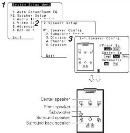
flowchart
graph TD
    A["System Setup Menu"] --> B["1. Auto Setup/Room EQ"]
    B --> C["2. Speaker Setup"]
    C --> D["3. Audio If"]
    D --> E["4. Video Si"]
    E --> F["5. Advanced"]
    F --> G["6. Option I"]
    G --> H["Exit"]
    C --> I["2. Speaker Setup"]
    I --> J["3. 1. Speaker Config."]
    J --> K["2. Subwoofer Setup"]
    K --> L["3. Distance"]
    L --> M["4. Channel"]
    M --> N["5. Crossov"]
    N --> O["Exit"]
    C --> P["2-1. Speaker Config."]
    P --> Q["Center Speaker"]
    P --> R["Front Speaker"]
    P --> S["Subwoofer"]
    P --> T["Surround back speaker"]
    Q --> U["Center Sp."]
    Q --> V["Center Sp."]
    Q --> W["Subwoofer"]
    Q --> X["No"]

- Select "Large" or "Small" not according to the actual size of the speaker but according to the speaker's capacity for playing low frequency (bass sound below the frequency set for the Crossover Frequency) signals. If you do not know, try comparing the sound at both settings (setting the volume to a level low enough so as not to damage the speakers) to determine the proper setting.
ENGLISH
ENGLISH
Advanced Setup – Part 2 Advanced Setup – Part 2
Setting the Subwoofer Setup
Select the method of playback of the subwoofer for playing the low bass signals.
1 Press △△ ▽ to select "Subwoofer Setup", then press ENTER.
2 Press ◁ ◁ | to set.
LFE:
For any channels) that are set to "Large", low frequencies in that channel's corresponding source are directed to that loudspeaker only. The low frequencies played from the subwoofer are only the LFE signals and the low frequencies of channels set to "Small".
LFE+Main:
Low frequencies from speaker channels that have been set to "Large" are reproduced from those speakers as well as from the subwoofer(s).
3 Press ENTER.
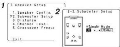

- The subwoofer mode setting is only valid when and "Yes" is set for the subwoofer in the "Setting the Speaker Configuration".
- Select the "LFE+Main" mode if you want low frequency signals to always be played from the subwoofer channel.
- Select the mode achieving a voluminous bass sound when playing music or movie sources.
Setting the Distance
This parameter is for optimizing the timing with which the audio signals are produced from the speakers and subwoofer according to the listening position.
Preparations:
Measure the distances between the listening position and the speakers (L1 to L8 on the diagram at the below).
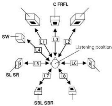
flowchart
graph TD
    A["C FRFL"] -->|L1| B["Switch"]
    A -->|L2| C["Switch"]
    A -->|L3| D["Switch"]
    A -->|L4| E["Switch"]
    A -->|L5| F["Switch"]
    A -->|L6| G["Switch"]
    A -->|L7| H["SBL SBR"]
    A -->|L8| I["SBL SBR"]
    J["SW"] --> K["Switch"]
    K --> L["L1"]
    K --> M["L2"]
    K --> N["L3"]
    K --> O["L4"]
    K --> P["L5"]
    K --> Q["L6"]
    R["Listening position"] --> S["Switch"]
    R --> T["Switch"]
    R --> U["Switch"]
1 Press △△ to select "Distance", then press ENTER.
2 Press ◀◀ to select "Meters" or "Feet".
3 Press △△ to select the speaker, then press ◀◀ to set.
4 Press ENTER.
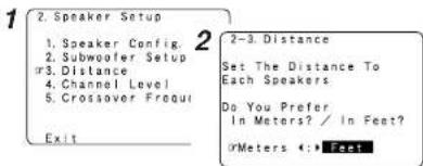
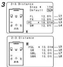

- Press^to select "Step", then press <◀ ptp change the amount of variation if so desired.
- The distance changes in units of 1 foot (0.1 meters) or 0.1 foot (0.01 meters) each time the button is pressed. Select the value closest to the measured distance.
- Please note that the difference of distance for every speaker should be 20 ft (6.0 m) or less. If you set an invalid distance, a CAUTION notice, such as screen right will appear. In such cases, move the appropriate speaker to the position of the displayed value.
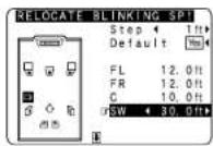
Advanced Setup – Part 2 Advanced Setup – Part 2
Setting the Channel Level
Set the volume of the various speakers so that the sound output from the speakers and the subwoofer seems to have the same volume level.
1 Press △△ to select "Channel Level", then press ENTER.
2Press ◀◀ |to set.
Auto:
Adjust the level while listening to the test tones produced automatically from each speaker.
Test tones are automatically emitted from each speaker.
Manual:
Adjust with the speaker from which the test tone is output switched manually.
3 Press △△ to select "Test Tone Start", then press ◀ to select "Yes".
When "Auto" mode is selected:
Press ◀◀ to adjust the volume.
-1 • Test tones are output automatically, in the order shown below.
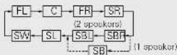
* The volume can be adjusted within the range -12.0 dB to +12.0 dB.
When "Manual" mode is selected:
-2 Press △△ to select the speaker, then press ◀◀ to adjust the volume.
5 Press ENTER.
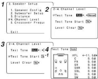

- To cancel the setting, press and select "Level Clear", then press and select "Yes".
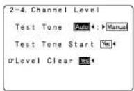
- To adjust the channel level separately for the different play modes after setting the channel level, perform the operation on page 36.
ENGLISH
□ Adjusting the test tone using the remote control unit
Adjustment of the test tones using the remote control unit is only possible in the "Auto" mode and only valid in the STANDARD (Dolby / DTS Surround) mode. The adjusted levels are automatically stored for the different surround modes.
1 Press [TEST TONE]. Test tones are output from the different speakers.
2 Press ◀◀ to adjust the volume.
3 Press [TEST TONE].
ENGLISH
Setting the Crossover Frequency
Set the frequency (Hz) below which the bass sound of the various speakers is to be output from the subwoofer. For speakers that are set to "Small", frequencies under the crossover frequency are cut before the signal is output, and the low frequency component that was cut is output from the subwoofer or the speakers that are set to "Large".
1 Press to select "Crossover Frequency", then press ENTER.
2 Press ◀◀ to set.
40, 60, 80, 90, 100, 110, 120, 150, 200, 250 Hz: Set as desired according to your speakers' bass playback ability.
3 Press ENTER.
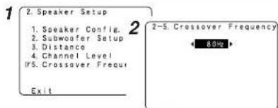

- The crossover frequency mode is valid only when subwoofer is set to "ON", and when one or more speakers are set to "Small", as described in section "Setting the Speaker Configuration" (Page 60).
- If "LFE+Main" is set at "Subwoofer Setup", "SW:LFE+Main" (page 61) is displayed at the top right of the screen.
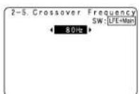
- Set to "80 Hz" when using regular speakers. When using small speakers, we recommend setting to a higher frequency.
Others Setup
Setting the Room Equalizer Setup
Set the Room Equalizer setting with "All" or "Assign" for each surround mode.
1 Press △△ ▽ to select "Room EQ Setup", then press ENTER.
2 Press ◀◀ to set, then press ENTER.
All: Sets the equalizer for all surround modes.
Assign: Sets the equalizer individually for each surround mode (page 28).
3 When "All" is selected: Press ◀◀ to set.
OFF: The equalizer is not used.
Normal: Adjust the frequency response of all speaker suitable for general surround system.
Front: Adjusts the frequency response of the surround speakers to match the characteristics of the front channel speakers.
Flat: Adjusts the frequency response of all speakers to the flattest response. This mode is suitable for multi-channel music surround sound sources.
Manual: Selects the setting value that was set in the "Setting the Manual Equalizer Setup" (Page 57).
4 Press ENTER.
Advanced Setup – Part 2 Advanced
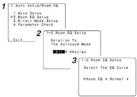

- The equalizer setting of "Normal", "Front" and "Flat" can be selected after performing the Auto Setup.
- When the speaker set as "None" with the Auto Setup is changed to on manually, the equalizer of "Normal", "Front" and "Flat" cannot be used.
- When headphones are connected, the Room Equalizer cannot be used.
Advanced Setup – Part 2 Advanced Setup – Part 2
Setting the Direct Mode Setup
Set the ON/OFF setting of Room Equalizer, in the case of the surround mode is in "DIRECT" or "PURE DIRECT".
1 Press △△ ▽to select "Direct Mode Setup", then press ENTER.
2 Press ◀◀ [to set.
ON.OFF:
Select "ON" to use the room equalizer, "OFF" if you do not want to use it.
3 Press ENTER.
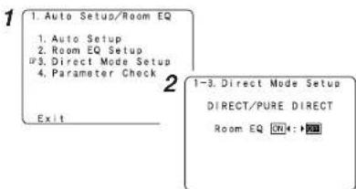
Check the parameter
The results of the measured items can be checked.
This item is displayed, after the measurement result of the "Auto Setup" is decided.
1 Press △△ ∇ to select "Parameter Check", then press ENTER.
2 Press △ △ to select the item, then press ENTER.
* For instructions on checking the results of each item (page 12).
3 Press △▽to select "EQ Parameter Check", then press ENTER.
4 Press △△ ▽ to select the type of equalizer, then press ENTER.
5 Press ◀◀ to select the speaker.
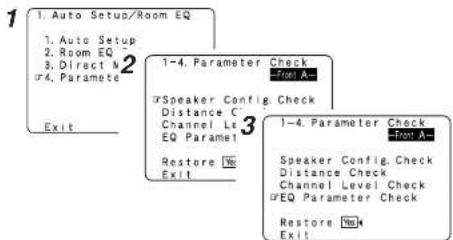
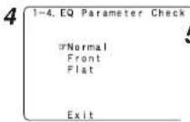
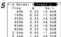
ENGLISH

• To reset;
Press △△ to select "Restore" at the "Parameter Check" screen, then press ◀◀
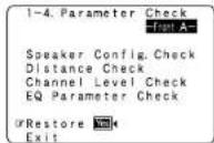
ENGLISH
![[MODE SELECTOR 1] [MODE SELECTOR 2] ZONE2 OFF [NUMBER] [MAIN ON]](/content/2026/05/817266/images/39804ca090391e990a321982a84d70274985523712e57063478dc6b5eab237ef.jpg)
Operating the remote control unit
Operating DENON audio components
1 Set [MODE SELECTOR 1] to "AUDIO".
2 Set [MODE SELECTOR 2] to the position for the component to be operated (CD, CD-R/MD or TAPE).
3 Operate the audio component.
* For details, refer to the component's operating instructions. * While this remote control is compatible with a wide range of infrared controlled components, it may be the case that some component models cannot be operated with this remote control.
Setting the preset memory function
- DENON and other makes of components can be operated by setting the preset memory.
- This remote control unit can be used to operate components of other manufacturers without using the learning function by registering the manufacturer of the component as shown in the list of preset codes (End of this manual).
• Operation is not possible for some models.
1 Set [MODE SELECTOR 1] to "AUDIO" or "VIDEO".
Set to the AUDIO side for the CD, TAPE or CD-R/MD position, and to the VIDEO side for the DVD/VDP, DBS/CABLE, VCR or TV position.
2 Set [MODE SELECTOR 2] to the component to be registered.
3 Press [ZONE2 OFF] and [MAIN ON] at the same time.
• The indicator starts flashing.
4 Referring to the included list of preset codes, press [NUMBER] to input the preset code (a 3-digit number) for the manufacturer of the component whose signals you want to store in the memory.
5 Tostore the codes of another component in the memory, repeat steps 1 to 4.

- The signals for the pressed buttons are emitted while setting the preset memory. To avoid accidental operation, cover the remote control unit's transmitting window while setting the preset memory.
- Depending on the model and year of manufacture, this function cannot be used for some models, even if they are of makes listed in the list of preset codes.
- Some manufacturers use more than one type of remote control code. Refer to the included list of preset codes to change the number and verify correct operation.
- The preset memory can be set for one component only among the following: CD-R/MD, DVD/MDP and DBS/CABLE.
Operating the remote control unit Operating the remote control unit
Operating a component stored in the preset memory
1 Set [MODE SELECTOR 1] to "AUDIO" or "VIDEO".
* Set to the AUDIO side for the CD, TAPE or CD-R/MD position, and to the VIDEO side for the DVD/VDP, DBS/CABLE, VCR or TV position.
2 Set [MODE SELECTOR 2] to the component you want to operate.
3 Operate the component.
* For details, refer to the component's operating instructions. * Some models cannot be operated with this remote control unit.
![[OFF] [SHIFT] [CHANNEL +] [▶], [■], [■], [A/B], [◀], [DISC SKIP +] [◀◀ ▶▶▶], [◀◀◀▶▶▶-] [VCR CH + -] [MODE SELECTOR 1] [ON/SOURCE] [SETUP], [△▽◀▶▶], [AUDIO], [ENTER], [DISPLAY], [RETURN], [MENU] [MODE SELECTOR 2]](/content/2026/05/817266/images/9561db9fa14ae31baca4fb458015c2921a5fba4ad28d34e56886af1620ab1252.jpg)
![[NUMBER] (0-9, +10) [TV/VCR] [TUNING + - ], [TV VOL. + - ], [MODE/MENU] [BAND/PICTURE ADJUST], [MEMORY/SUBTITLE] [SETUP], [△▽ ◀>], [AUDIO], [ENTER], [DISPLAY], [RETURN]](/content/2026/05/817266/images/fddba769b011b7ad3ff9ca7703e592a97d1f4d586807389a1093ba632c08c5e8.jpg)
ENGLISH
ENGLISH
Operating the remote control unit Operating the remote control unit
□ Functions of buttons for the different devices
[Front]
| Device operated | CD player | CD recorder | MD recorder | Tape deck | DVD player | Video disc player | Video deck | Satellite tuner | Cable TV | TV(Monitor) |
| MODE SELECTOR 1 | AUDIO | VIDEO | ||||||||
| MODE SELECTOR 2 | CD | CD-R / MD | TAPE | DVD / VDP | VCR | DBS / CABLE | TV | |||
| OFF | - | - | - | - | Power off | - | - | - | - | - |
| ON / SOURCE | - | - | - | - | Power on | Power on /Standby | Power on /Standby | Power on /Standby | Power on /Standby | Power on /Standby |
| SHIFT | Preset channel selection | Preset channel selection | Preset channel selection | Preset channel selection | ||||||
| CHANNEL - | Preset channel selection | Preset channel selection | Preset channel selection | Preset channel selection | Channels - | Channels - | Channels - | Channels - | Channels - | Channels - |
| CHANNEL + | Preset channel selection | Preset channel selection | Preset channel selection | Preset channel selection | Channels + | Channels + | Channels + | Channels + | Channels + | Channels + |
| ▶ | Play | Play | Play | Forward play Play PlayPlay | Punch through | Punch through | Punch through | |||
| ■ | Stop Stop | Stop Stop Stop | Stop Stop | |||||||
| II, A/B | Pause | Pause | Pause | A/B switching | Pause | Pause | Pause | |||
| ◀. DISC SKIP + | Disc skip - | Reverse play | Disc skip | |||||||
| ◀◀ | Search (reverse) | Search (reverse) | Search (reverse) | Rewind | Search (reverse) | Search (reverse) | Search (reverse) | |||
| ▶▶ | Search (forward) | Search (forward) | Search (forward) | Fast forward | Search (forward) | Search (forward) | Search (forward) | |||
| I◀◀, VCR CH - | Skip (reverse) | Skip (reverse) | Skip (reverse) | - | Skip (reverse) | Skip (reverse) | Channels - | |||
| ▶▶I, VCR CH + | Skip (forward) | Skip (forward) | Skip (forward) | - | Skip (forward) | Skip (forward) | Channels + | |||
| SETUP | - | - | - | - | Setup | - | - | - | - | - |
| △▽ ◀ ▷ | - | - | - | - | Cursor operation | - | - | Cursor operation | Cursor operation | Cursor operation |
| AUDIO | Audio | |||||||||
| ENTER | - | - | - | - | Enter | - | - | Enter | Enter | Enter |
| DISPLAY | - | - | - | - | Display selection | - | - | Display selection | Display selection | Display selection |
| RETURN | - | - | - | - | Return | - | - | Return | Return | Return |
| MENU | Menu | Menu | Menu | Menu | ||||||
ENGLISH
Operating the remote control unit Operating the remote control unit
[Rear]
| Device operated | CD player | CD recorder | MD recorder | Tape deck | DVD player | Video disc player | Video deck | Satellite tuner | Cable TV | TV(Monitor) |
| MODE SELECTOR 1 | AUDIO | VIDEO | ||||||||
| MODE SELECTOR 2 | CD | CD-R / MD | TAPE | DVD / VDP | VCR | DBS / CABLE | TV | |||
| NUMBER (0 ~ 9, +10) | - | - | - | - | Number input / Track selection | Number input / Track selection | - | Channels | Channels | Channels |
| TV/ VCR | - | - | - | - | Input mode selection | Input mode selection | Input mode selection | Input mode selection | Input mode selection | Input mode selection |
| TUNING + / TV VOL + | Tuning | Tuning | Tuning | Tuning | Volume control i | Volume control i | Volume control i | Volume control i | Volume control i | Volume control i |
| TUNING - / TV VOL - | Tuning | Tuning | Tuning | Tuning | Volume control | Volume control | Volume control | Volume control | Volume control | Volume control |
| MODE / MENU | Auto/Manual switching | Auto/Manual switching | Auto/Manual switching | Auto/Manual switching | Menu | - | - | Maru | Maru | Menu |
| SETUP | - | - | - | - | - | - | - | Setup - | ||
| V < D | - | - | - | - | Cursor operation | - | - | Cursor operation | Cursor operation | Cursor operation |
| AUDIO | - | - | - | - | Audio | - | - | - | - | - |
| BAND / PICTURE ADJUST | AM/FM/XM switching | AM/FM/XM switching | AM/FM/XM switching | AM/FM/XM switching | Picture adjust | - | - | - | - | - |
| ENTER | - | - | - | - | Enter | - | - | Enter | Enter | Enter |
| MEMORY / SUBTITLE | Preset memory | Preset memory Preset monImpact memory | Subtile | - | - | - | - | |||
| DISPLAY | - | - | - | - | Display selection | - | - | Display selection | Display selection | Display selection |
| RETURN | - | - | - | - | Return | - | - | Return | Return | Return |
| Default setting (Preset code) | DENON(111) | DENON(111) | - | DENON(111) | DENON(111) | - | HITACHI(108) | - | ABC(007) | HITACHI(134) |
| Special remarks | 1 | 1 | 1 | 1. 2 | 1 | 1. 3 | 1. 3 | |||
Special remarks:
① It is only possible to set the preset memory for one device per mode. When a new code is preset, the previous code is automatically deleted.
② Note that the function names of the DVD buttons on the remote control unit may differ for some brands. Check beforehand.
③ The CD, CD-R/MD, TAPE, VCR or DVD/VDP buttons can be assigned to a TV or satellite tuner (or cable TV) (page 69).
ENGLISH
Operating the remote control unit Operating the remote control unit
![[MODE SELECTOR 1] [MODE SELECTOR 2] DENOM [MEMORY] [INPUT MODE]](/content/2026/05/817266/images/f8d9cd54c1eb73c4594d9ec50768851dc1f9912507ec414b2ae9a560d17890d5.jpg)
Setting the punch through function
"Punch Through" is a function allowing you to operate ▶, ■, ◀◀, ▶▶, ◀◀ and ▶▶ on CD, TAPE, CD-R/MD, DVD/VDP or VCR components when in the DBS/CABLE or TV mode. By default, nothing is set.
1 Set [MODE SELECTOR 1] to "VIDEO".
2 Set [MODE SELECTOR 2] to the component to be registered (DBS/CABLE or TV).
3 Press [MEMORY] and [INPUT MODE] at the same time. • The indicator starts flashing.
4 Input the number of the component you want to set.
| No. | |
| CD | 1 |
| TAPE 2 | |
| CD-R/MD 3 | |
| DVD/VDP 4 | |
| VCR 5 | |
| No setting 0 |
Additional Information
About the speakers
Surround back speakers
Sound position directly to the rear can be achieved easily by adding a surround back speaker to a 5.1-channel system. In addition, the acoustic image extending between the sides and the rear is narrowed, thus greatly improving the expression of the surround signals for sounds moving from the sides to the back and from the front to the point directly behind the listening position.
Change of positioning and acoustic Image with 5.1-channel systems
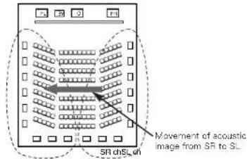
Change of positioning and acoustic image with 6.1-channel systems
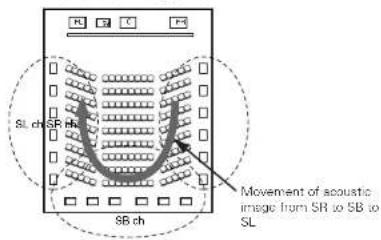
In addition to sources recorded in 6.1-channels, the surround effect of conventional 2- to 5.1-channel sources can also be enhanced.
☐ Number of surround back speakers
We recommend using two speakers.
When using dipolar speakers in particular, be sure to use two speakers.
☐ Placement of the surround left and right channels when using surround back speakers
We recommend installing the speakers for the surround "L" and "R" channels a bit forward.
Examples of speaker layouts
Below we introduce examples of speaker layouts. Refer to these to arrange your speakers according to their type and how you want to use them.
[1] Using surround back speaker(s)
① When mainly playing movies
Recommended when your surround speakers are single or 2-way speakers.
![[As seen from above] Front speakers Center speaker Monitor Subwoofer 50° Surround speakers 50°](/content/2026/05/817266/images/39a011667d81569ed0801bc462055c094a8277647aa241d5f28e44653b5e2d64.jpg)
Surround back speakers
![[As seen from the side] Surround speaker Surround back speaker Front speaker 2 to 3 feet/ 60 to 90 cm Point slightly downwards](/content/2026/05/817266/images/3ac56b31091513245e1c4696fc7005a0935670e204fda88281bd73e6a6d76f16.jpg)
② When playing movies and musics
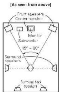
flowchart
graph TD
    A["Front speakers Center speaker"] --> B["Monitor Subwoofer"]
    B --> C["Surround speakers"]
    C --> D["Surround back speakers"]
    style A fill:#f9f,stroke:#333
    style B fill:#ccf,stroke:#333
    style C fill:#cfc,stroke:#333
    style D fill:#fcc,stroke:#333
![[ As seen from the side ] Surround speaker Front speaker 2 to 3 feet/ 60 to 90 cm Surround back speaker Point slightly downwards](/content/2026/05/817266/images/f788f77d9d5d012154e19bd0a85263d458d472c0b47a069bd3056f1665fd9a53.jpg)
[2] When not using surround back speakers
![[As seen from above] Front speakers Center speaker Monitor Subwoofer 60° 120° Surround speakers](/content/2026/05/817266/images/30832734b6a3f250a19fd3ca65e8e81dc826646c9412467dd9badfea7ef2abdd.jpg)
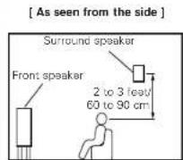
ENGLISH
Additional Information Additional Information
Surround
The AVR-887 is equipped with a digital signal processing circuit that lets you play program sources in the surround mode to achieve the same sense of presence as in a movie theater.
Dolby Surround
[1] Dolby Digital
Dolby Digital is the multi-channel digital signal format developed by Dolby Laboratories.
A total of 5.1-channels are played: three front channels ("FL", "FR" and "C"), two surround channels ("SL" and "SR") and the "LFE" channel for low frequencies.
Because of this, there is no crosstalk between channels and a realistic sound field with a "three-dimensional" feeling (sense of distance, movement and positioning) is achieved.
A real, overpowering sense of presence is achieved when playing movie sources in AV rooms as well.
[2] Dolby Pro Logic II
Dolby Pro Logic II is a matrix decoding technology developed by Dolby Laboratories. Regular music such as that on CDs is encoded into 5 channels to achieve an excellent surround effect.
The surround channel signals are converted into stereo and full band signals (with a frequency response of 20 Hz to 20 kHz or greater) to create a "three-dimensional" sound image offering a rich sense of presence for all stereo sources.
[3] Dolby Pro Logic IIx
Dolby Pro Logic IIIx is a further improved version of the Dolby Pro Logic II matrix decoding technology.
Audio signals recorded in 2 channels are decoded to achieve a natural sound with up to 7.1-channels.
There are three modes: "Music" suited for playing music, "Cinema" suited for playing movies, and "Game" which is optimum for playing games.
□ Sources recorded in Dolby Surround
Sources recorded in Dolby Surround are indicated with the following logo marks.
Dolby Surround support mark: DOLEY SURROUND
Manufactured under license from Dolby Laboratories. "Dolby", "Pro Logic" and the double-D symbol are trademarks of Dolby Laboratories.
DTS Digital Surround
DTS Digital Surround is a digital surround format developed by Digital Theater Systems of the United States.
The number of playback channels and the playing band is the same as for Dolby Digital (5.1-channels).
The compression rate of the audio data when it was recorded on the medium is lower than for Dolby Digital, so there is more information when the data is decoded, resulting in richer, clearer sound quality.
MANUFACTURED UNDER LICENSE FROM DIGITAL THEATER SYSTEMS, INC.
U.S. PAT. NO'S. 5,451,942; 5,956,674; 5,974,380; 5,978,762; 6,226,616; 6,487,535 AND OTHER U.S. AND WORLD-WIDE PATENTS ISSUED AND PENDING.
"DTS", "DTS-ES", "Neo:6", AND "DTS 96/24" ARE TRADEMARKS OF DIGITAL THEATER SYSTEMS, INC. © 1996, 2003 DIGITAL THEATER SYSTEMS, INC. ALL RIGHTS RESERVED.
DTS-ES™
DTS-ES is a new surround format developed by Digital Theater Systems.
A sound image and sense of positioning can be achieved by adding a surround back ("SB") channel to the conventional 5.1-channels.
DTS-ESTM Discrete 6.1:
This is the latest format, in which all 6.1-channels, including the "SB" channel, are recorded independently. Since the different channels are independent, the sound can be designed with total freedom.
DTS-ESTM Matrix 6.1:
With this format, the "SB" channel is matrix-encoded and inserted into the "SL" and "SR" channels, then decoded for the "SL", "SR" and "SB" channels upon playback. This achieves a surround sound more faithful to the artist's sound design intentions than with conventional 5.1- or 6.1-channel systems.
DTS NEO:6 surround
This is a matrix decoding technology for 6.1-channel surround playback of 2-channel sources.
The optimum decoding for the type of signal source to be played can be selected. There are two modes.
DTS NEO:6 CINEMA:
This mode is suited for playing movies. It achieves the same type of sound as in a movie theater, even with 2 channels.
DTS NEO:6 MUSIC:
This mode is suited for playing music. A natural sense of expansion is added to the sound field.
DTS 96/24
DTS 96/24 is a multi-channel digital signal format developed by Digital Theater Systems.
The sampling frequency is raised to achieve 5.1-channel playback with high quality sound (sampling frequency: 96 kHz, quantization: 24 bits).
Additional Information
Neural Surround
Neural Surround™, a breakthrough in audio technology, will bring the excitement of surround music to more of America's listening audience. It provides the rich envelopment and discrete image detail of surround sound in a format 100 % compatible with stereo. With superior spectral resolution and channel separation, Neural Surround™ draws the brain's attention to sonic details in musical instruments, vocals, and ambience that are typically masked by other playback systems. This allows the listener to fully experience the richness and subtleties in recorded performance as never before. As the chosen format for XM Satellite Radio's new XM HD surround programming, Neural Surround will help deliver more surround music to more listeners than any other broadcast format. XM Satellite Radio will be the first radio company -to broadcast surround sound on the radio 24 hours a day and will offer three channels fully dedicated to Neural Surround™ music. This alone will amount to more than 25,000 hours of Neural Surround™ music each year.

neural
公司声明自《中国
- This product is manufactured under license from Neural Audio Corporation.
D&M Holdings Inc. hereby grants the user a non-exclusive, non-transferable, limited license right exercisable to use the NA SURROUND Technology and other US and World Wide Patents Pending technology.
"Neural" and "Neural Audio" and "Neural Surround" Are trademarks of Neural Audio Corporation. All Rights Reserved.
HDMI (High-Definition Multimedia Interface)
HDMI is a digital interface standard for next generation TVs based on DVI (Digital Visual Interface) standards and optimized for use in consumer equipment.
Non-compressed digital video and multi-channel audio signals are transmitted with a single connection.
HDMI is also compatible with HDCP (High-bandwidth Digital Contents Protection), a technology for protecting copyrights that encrypts digital video signals in the same was as with DVI.
HDMI
- "HDMI", "HDMI High-Definition Multimedia Interface" are trademarks or registered trademarks of HDMI Licensing LLC.
ENGLISH
Troubleshooting
If a problem should arise, first check the following.
-
Are the connections correct?
-
Have you operated the receiver according to the Operating Instructions?
-
Are the speakers and other components operating properly?
If this unit is not operating properly, check the items listed in the table below. Should the problem persist, there may be a malfunction. Disconnect the power immediately and contact your store of purchase.
| Cause PageMeasuresSymptom | |||
| Display not lit and sound not produced when POWER switch set to on. | Power supply cord not plugged in securely. | Check the insertion of the power supply cord plug. | 24 |
| Display lit but sound not produced. | Speaker cables not securely connected.FUNCTION knob position is not appropriate.Volume control set to minimum.MUTING is on.No digital signal is being input. | Connect securely.Switch to the proper position.Turn volume up to suitable level.Switch off MUTING.Properly select a digital signal input source. | 825252643 |
| Nothing is displayed on monitor. | AVR-387's video output terminals and monitor's input terminals are not properly connected.Monitor's input setting is wrong.The PURE DIRECT mode is set.Playor connected with component terminal, TV connected with video terminal (yellow) or 5 Video terminal. | Check that the connections are correct.Set the monitor's input selector to the terminals to which video signals are connected.Set a surround mode other than the PURE DIRECT mode.Down conversion is not possible for progressive video signals.Make the interlace settings on the player. | 9,14 ~ 24—27— |
| No DTS sound is produced. | DVD player's audio output setting is not set to bit stream.DVD player is not DTS-compatible.A VR-887's input setting is set to analog. | Make the DVD player's default settings.Use a DTS-compatible player.Set to "AUTO" or "DTS". | ——25 |
| Copying from DVD to VCR is not possible. | Copying between a source such as DVD and a VCR is not usually possible, as DVDs are often encoded with copy-protection signals that prevent VCR recording. | Copying is not possible. — | |
ENGLISH
Troubleshooting
Troubleshooting
| PageM | |||
| No sound is produced from subwoofer. | Subwoofer's power is not on.Subwoofer's initial setting is set to "NO".Subwoofer's output is not connected.The subwoofer's channel volume level is set to "OFF". | Turn on the power.Set the setting to "YES".Connect properly.Turn the subwoofer's channel volume level up. | —608, 2336 |
| No test tones are produced. | Surround mode is set to a mode other than STANDARD (Dolby/OTS Surround). | Set to STANDARD (Dolby/DTS Surround). | — |
| No sound is produced from surround speakers. | Surround mode is set to "STEREO". | Set to a mode other than "STEREO". | — |
| This unit does not operate properly when remote control unit is used. | Batteries dead.Remote control unit too far from this unit.Obsstacle between this unit and remote control unit.Different button is being pressed.and ends of batteries inserted in reverse. | Replace with new batteries.Move closer.Remove obstacle.Press the proper button.Insert batteries properly. | 333—3 |
| An image is not projected with an HDMI connection. | AVR-887's HDMI output terminals and monitor's input terminals are not properly connected.No HDMI signal is being input.The connected monitor equipment or other equipments do not support HDCP.The output format of the connected player (HDMI FORMAT) does not match the supported input format of connected monitor equipments. | Check the HDMI connection.P properly select HDMI signal input source.The AVR-887 will not output video signal unless the other equipment supports HDCP.C check whether the output format of the connected player (HDMI FORMAT matches the supported input format of connected monitor equipments. | 19531919 |
| The HDMI audio is not output. | The AVR-887 does not play HDMI audio signals.The HDMI audio signals are not output from the connected monitor device. | Set the HDMI audio playback setting at the "HDMI in Assignment" settings to "AMP".Set the HDMI audio playback setting at the "HDMI in Assignment" settings to "TV". | 5353 |
| uresCaSysSymptom | PageMeasuresCa | ||
| Power has turned off and the power indicator is blinking red. | The set's internal temperature has risen and the protection circuit has been activated.The core wires of the speaker cables are touching each other or the AVR-887's rear panel, activating the protection circuit.A VR-887 is malfunctioning. | Put the AVR-887 in a well-ventilated place.T um off the power, then wait for the set to fully cool off before turning the power back on.Check the connections of all the speaker cables.T um off the power and contact a DENON customer service center. | 8888 |
| Sound is only produced from the center speaker. | You are playing a monaural source (TV, AM radio broadcast, etc.) in the STANDARD (Dolby/DTS Surround) mode. | When playing monaural sources, select a surround mode other than STANDARD (Dolby/DTS Surround) mode. | 35 |
| "DOLBY DIGITAL" is not displayed. | DVD player's digital audio output setting is not proper. | Check the DVD player's audio output setting.For details, see the DVD player's operating instructions. | — |
| displayed in the XM mode. | AVR-887's XM connectors and the XM Passport System is not properly connected. | Check that the connection are correct. | 22"CHECK ANTEN |
| displayed in the XM mode. | The signal cannot be received. | Reposition your XM Passport System. | 39"NO SIGNAL" is |
| "OFF AIR" is displayed in the XM mode. | The selected channel is not currently broadcasting. | Select the another channel. | 39 |
| Receiving only XM channels 0 and 1. | The XM Tuner is not activated. | Contact XM Radio. | 38 |
Specifications
□ Audio section
• Power amplifier
Rated output: Front (A, B):
100 W + 100 W (8 Ω/ohms, 20 Hz \~ 20 kHz with 0.08 % T.H.D.)
135 W + 135 W (6 Ω/ohms, 1 kHz with 0.7 % T.H.D.)
Center:
100 W (8 Ω/ohms, 20 Hz \~ 20 kHz with 0.08 % T.H.D.)
135 W (6 Ω/ohms, 1 kHz with 0.7 % T.H.D.)
Surround:
100 W + 100 W (8 Ω/ohms, 20 Hz \~ 20 kHz with 0.08 % T.H.D.)
135 W + 135 W (6 Ω/ohms, 1 kHz with 0.7 % T.H.D.)
Surround Back
100 W + 100 W (8 Ω/ohms, 20 Hz - 20 kHz with 0.08 % T.H.D.)
135 W + 135 W (6 Ω/ohms, 1 kHz with 0.7 % T.H.D.)
20 W x 2 ch (8 Ω/ohms)
170 W x 2 ch (4 Ω/ohms)
Front: A or B 6 \~ 16 Ω/ohms
A + B 12 \~ 16 Ω/ohms
Center, Surround, Surround. Back: 6 - 16 Ω/ohms
- Analog
Input sensitivity / Input Impedance: 200 mV / 47 kΩ/kohms
Frequency response: 10 Hz \~ 100 kHz: +1, -3 dB (DIRECT mode)
S/N: 100 dB (IHF-A weighted) (DIRECT mode)
Distortion: 0.008 % (20 Hz - 20 kHz) (DIRECT mode)
Rated output: 1.2 V
- Phono equalizer (PHONO input — REC OUT)
Input sensitivity: 2.5 mV
RIAA deviation: ±1 dB (20 Hz to 20 kHz)
S/N: 74 dB (A weighting, with 5 mV input)
Rated output / Maximum output: 150 mV / 7 V
Distortion factor: 0.03 % (1 kHz, 3 V)
□ Video section
• Standard video terminals
Input / output level and Impedance: 1 Vp p, 75 Ω/ohms
Frequency response: 5 Hz \~ 10 MHz — +0, -3 dB
• S-Video terminals
Input / output level and impedance: Y (brightness) signal — 1 Vp-p, 75 Ω/ohms
C (color) signal — 0.286 Vp-p, 75 Ω/ohms
Frequency response: 5 Hz \~ 10 MHz — +0, -3 dB
• Color component video terminal
Input / output level and impedance: Y (brightness) signal — 1 Vp-p, 75 Ω/ohms
Pp/Ca signal — 0.7 Vp-p, 75 Ω/ohms
P_H/C_H signal — 0.7 Vp-p, 75 Ω/ohms
Frequency response: 5 Hz \~ 100 MHz — +0, -3 dB
□ Tuner section
[FM]
[AM]
Receiving Range:
note: V at 75 Ω/5nm/s, 0dB = 1× 10^-6W
520 kHz \~ 1710 kHz
Usable Sensitivity:
1.0 μV (11.2 dBf)
18μV
50 dB Quietling Sensitivity:
MONO 1.6 μV (15.3 dB)
S/N (IHF-A):
STEREO 23 μV (38.5 dBI)
MONO 77 dB (IHF-A weighted)
Total Harmonic Distortion (at 1 kHz):
STEREO 72 dB IIHF-A weighted
MONO 0.15%
STEREO 0.3%
□ General
Power supply:
AC 120 V, 60 Hz
Power consumption:
5.5 A
Maximum external dimensions:
1 W Max (Standby)
434 (W) × 171 (H) × 417 (D) mm (17-3/32" × 6-47/64" × 18-27/64")
13 kg (28 lbs 11 oz)
□ Remote control unit (RC-1043)
Batteries:
R6P/AA Type (Two batteries)
External dimensions:
52 (W) × 243 (H) × 21 (D) mm (2-3/64" × 9-9/16" × 53/64")
Mass:
175 g (Approx. 6.2 oz) (included batteries)
^6 For purposes of improvement, specifications and design are subject to change without notice.
□ List of preset codes
| DVD | ASA | 042 | Go Video 047, 048 | Minolta 013, 023 | |
| Denon | 014, *[111] | Asha | 087 | Goldstar 000, 006, 012, 062, 088 | Mitsubishi 001, 003, 008, 013, 014, |
| Aiwa | 009 | Audio Dynamic | 005, 085 | Gradiente 094 | 017, 027, 029, 039, 040, |
| Hitachi 010 | Audiovox 088 | Grundig 042 | 041, 045, 097 | ||
| JVC 006, 011 | Beaumark | 087 | Harley Davidson 094 | Motorola 081 | |
| Konka 012, 013 | Broksonic | 086, 093 | Harman Kardon 040, 062 | Montgomery Ward 001, 002, 007, 009, 049, | |
| Magnavox 005 | Calix | 088 | Hi-O 091 | 063, 081, 115, 117 | |
| Mitsubishi 004 | Candle 006, 087, 088, 089, 090 | Hitachi 009, 013, 023, 026, 058, | MTC 009, 087, 094 | ||
| Panasonic | 014 | Canon | 049, 057 | *[108], 109, 110, 111 | Multitech 007, 009, 011, 087, 090, |
| Philips | 005, 015, 016, 017 | Capehart | 025, 055, 056, 071 | JC Penny 004, 005, 007, 023, 028, | 094 |
| Pioneer | 003, 008 | Carver | 015 | 049, 062, 085, 087, 088 | NAD 038 |
| Sanyo 018 | CCE | 095 | Jensen 013, 026 | NEC 004, 005, 006, 018, 026, | |
| Sony | 002, 019, 020 | Citizen | 006, 007, 087, 088, 089, | JVC 004, 005, 006, 026, 029, | 029, 045, 061, 062, 085 |
| Toshiba 001, 021, 022 | 090, 095 | 043, 044, 045, 046, 085 | Nikko 088 | ||
| Zenith | 023 | Craig | 007, 087, 088, 091, 115 | Kenwood 004, 005, 006, 026, 029, | Noblex 087 |
| Curtis Mathes | 006, 049, 073, 080, 087, | 033, 045, 095, 090 | Optimus 081, 088 | ||
| VDP | 090, 092 | Kodak 088 | Optonica 021 | ||
| Denon | 028, 029, 112 | Cybernex | 087 | Lloyd 009, 094 | Panasonic 024, 049, 064, 066, 067, |
| Magnavox 026 | Daewoo 025, 055, 059, 074, 089, | LXI 088 | 068, 069, 107 | ||
| Mitsubishi 028 | 093, 095, 096 | Magnavox 015, 016, 042, 049, 063, | Perdio 009 | ||
| Panasonic | 029, 030 | Daytron 025, 055 | 106 | Pentax 009, 013, 023, 058, 090 | |
| Philips | 026 | DSX 005, 085 | Magnin 087 | Philco 015, 016, 049 | |
| Pioneer | 028, 031 | Dumont | 053 | Marantz 004, 005, 006, 015, 042, | Philips 015, 021, 042, 049, 105 |
| RCA 032 | Dynatech | 009 | 049, 085, 090 | Pilot 088 | |
| Sony | 033, 034, 035, 036 | Electrohome | 001, 088, 097 | Marta 088 | Pioneer 005, 013, 029, 036, 037, |
| Electrophonic | 088 | MEI 049 | 038, 045, 085 | ||
| VCR | Emerson | 001, 009, 017, 027, 086, | Memorex 009, 033, 049, 053, 060, | Portland 025, 055, 090 | |
| Admiral | 081 | 088, 089, 092, 093, 097, | 081, 087, 088, 091, 094, | Proscan 063, 080 | |
| Aiko | 095 | 100, 101, 102, 103, 104, | 115 | Pulsar 060 | |
| Aiwa | 009 | 117 | Metz 123, 124, 125, 126, 127, | Quartz 033 | |
| Akai | 026, 027, 070, 072, 082, | Fisher 009, 028, 031, 053, 054, | 128 | Quasar 034, 035, 049 | |
| 083, 084 | 091, 099, 115 | MGA 001, 017, 027, 041, 097 | Radio Shack 001, 002, 021, 081, 087, | ||
| Alba | 055 | GE | 007, 011, 049, 050, 051, | MGN Technology 087 | 088, 091, 094, 097, 098, |
| Amstrad | 009 | 052, 073, 080, 087 | Midland 011 | 115 |
ENGLISH
| Radix 088 | |
| Randex 088 | |
| RCA 007, 013, 019, 023, 058,063, 064, 065, 073, 080,082, 087 | |
| Realistic 009, 021, 031, 033, 049,053, 081, 087, 088, 091,094, 097, 098 | |
| Ricoh 055 | |
| Salora 033, 041 | |
| Samsung 007, 011, 051, 059, 070,083, 087, 089, 113 | |
| Sanky 081 | |
| Sansui 005, 026, 029, 045, 061,085, 114 | |
| Sanyo 032, 033, 053, 087, 091,115, 116 | |
| SBR 042 | |
| Scott 017, 020, 086, 089, 093,117 | |
| Sears 013, 023, 028, 031, 033,053, 054, 088, 091, 098,099, 115 | |
| Sentra 055 | |
| Sharp 001, 002, 021, 097 | |
| Snogun 087 | |
| Sony 075, 076, 077, 078, 079,121, 122 | |
| STS 023 | |
| Sylvania | 009, 015, 016, 017, 041,049, 094 |
| Symphonic | 009, 094 |
| Tandy009 | |
| Tashiko | 009, 088 |
| Tatung 004, 026, 030 | |
| Teac 004, 009, 026, 094 | |
| Technics | 024, 049 |
| Teknika | 009, 010, 022, 049, 088, 094 |
| TMK | 087, 092 |
| Toshiba 013, 017, 020, 041, 059, 089, 098, 099, 117 | |
| Totevision | 007, 087, 088 |
| Unirech | 087 |
| Vector Research | 005, 062, 085, 089, 090 |
| Victor 005, 045, 046, 085 | |
| Video Concepts | 005, 027, 085, 089, 090 |
| Videcsonic | 007, 087 |
| Wards 013, 021, 023, 087, 088, 089, 091, 094, 097, 118, 119, 120 | |
| XR-1000 | 094 |
| Yamaha | 004, 005, 006, 026, 062, 085 |
| Zenith | 060, 078, 079 |
TV
| Admiral 045, 121 | |
| Adventura | 122 |
| Aiko 054 | |
| Akai | 016, 027, 046 |
| Aileron | 062 |
| A Mark | 007 |
| Amtron 061 | |
| Anam | 006, 007, 036 |
| Anam National | 061, 147 |
| AOC | 003, 007, 033, 038, 039, 047, 048, 049, 133 |
| Archer 007 | |
| Auciovox | 007, 061 |
| Bauer | 156 |
| Belcor | 047 |
| Bell & Howell | 045, 118 |
| Bradford | 061 |
| Brockwood | 003, 047 |
| Candle | 003, 030, 031, 032, 038, 047, 049, 050, 122 |
| Capchart | 003 |
| Celebrity | 046 |
| Circuit City | 003 |
| Citizen | 029, 030, 031, 032, 034, 038, 047, 049, 050, 054, 061, 095, 122, 123 |
| Concerto | 031, 047, 049 |
| Colortyme | 003, 047, 049, 135 |
| Contec | 013, 051, 052, 061 |
| Cony | 051, 052, 061 |
| Craig | 004, 061 |
| Crown 029 | |
| Curtis Mathes | 029, 034, 038, 044, 047, 049, 053, 095, 118 |
| Daewoo 027, 029, 039, 048, 049, 054, 055, 106, 107, 137 | |
| Daytron | 003, 049 |
| Dimensia 044 | |
| Dixi | 007, 015, 027 |
| Electroband | 046 |
| Electrohome | 029, 056, 057, 058, 147 |
| Elta | 027 |
| Emerson | 029, 051, 059, 060, 061, 062, 118, 123, 124, 139, 148 |
| Envision 038 | |
| Etron | 027 |
| Fisher 014, 021, 063, 064, 065, 118 | |
| Formenti | 155 |
| Fortress | 012 |
| Fujitsu 004, 062 | |
| Furai | 004, 062 |
| Futuretech | 004 |
| GE | 020, 036, 037, 040, 044,058, 066, 088, 119, 120,125, 147 |
| Goldstar 000, 015, 029, 031, 039,048, 051, 056, 057, 067,068, 069, 116 | |
| Grundy | 062 |
| Hitachi | 029, 031, 051, 052, 070,111, 112, 113, 124,* [134] |
| Hitachi Pay TV | 151 |
| Infinity | 017, 071 |
| Janeil 122 | |
| JBL | 017, 071 |
| JC Penny | 020, 034, 039, 040, 041,044, 048, 050, 058, 066,069, 076, 088, 090, 095,125, 136, 159 |
| JCB | 046 |
| JVC 019, 051, 052, 072, 073,091, 117, 126 | |
| Kawasho | 018, 046 |
| Kenwood | 038, 056, 057 |
| Kloss | 010, 032 |
| Kloss Novaceam | 005, 122, 127, 131 |
| KTV 074, 123 | |
| Loewe | 071 |
| Logik | 144 |
| Luxman | 031 |
| LXI | 008, 014, 017, 024, 040,044, 063, 071, 075, 076,077, 118, 125 |
ENGLISH
| Magnavox 005, 010, 017, 030, 033,038, 050, 056, 071, 078,079, 085, 089, 108, 109,110, 127, 131, 132, 145 |
| Marantz 015, 017, 071, 080 |
| Matsui 027 |
| Memorex 014, 027, 045, 083, 118,144 |
| Metz 160, 161, 162, 163 |
| MGA 001, 039, 048, 056, 057,058, 065, 081, 083 |
| Midland 125 |
| Minutz 066 |
| Mitsubishi 001, 016, 039, 048, 056,057, 058, 065, 081, 082,083, 105 |
| Montgomery Ward 011, 020, 144, 145, 146 |
| Motorola 121, 147 |
| MTC 031, 034, 039, 048, 095 |
| NAD 008, 075, 076, 128 |
| National 002, 036, 061, 147 |
| National Quenties 002 |
| NEC 031, 038, 039, 048, 057,084, 086, 135, 147 |
| Nikko 054 |
| NTC 054 |
| Optimus 128 |
| Optionica 011, 012, 093, 121 |
| Orion 004, 139 |
| Panasonic 002, 009, 017, 036, 037,071, 141, 143, 147 |
| Philco 005, 010, 030, 050, 051,056, 079, 085, 127, 131,132, 145, 147 |
| Philips | 006, 016, 017, 050, 051,056, 078, 087, 088, 089,131, 132, 147 |
| Pioneer | 124, 128, 142 |
| Portland | 054 |
| Price Club 095 | |
| Proscan Q40, Q44, 125 | |
| Proton | 035, 051, 092, 129 |
| Pulsar | 042 |
| Quasar | 036, 037, 074, 141 |
| Radio Shack | 011, 044, 063, 093, 118 |
| RCA Q40, Q44, 125, 130, 137,151, 152 | |
| Realistic | 014, 063, 093, 118 |
| Saisho | 027 |
| Samsung | 003, 015, 034, 053, 055,057, 094, 095, 136, 153 |
| Sansui | 139 |
| Sanyo | 013, 014, 021, 022, 063,064, 081, 096 |
| SBR 015 | |
| Schneider | 015 |
| Scott 062 | |
| Sears 008, 014, 021, 022, 023,024, 025, 040, 052, 057,062, 063, 064, 065, 073,075, 076, 097, 098, 125,159 | |
| Sharp | 011, 012, 013, 026, 093,099, 100, 104, 121 |
| Siemens | 013 |
| Signature | 049, 144 |
| Simpson | 050 |
| Sony | 043, 046, 138, 146, 150 |
| Soundesign | 030, 050, 062 |
| Spectricon | 007, 033 |
| Squareview | 004 |
| Supre-Macy | 032, 122 |
| Supreme | 046 |
| Sylvania 005, 010, 017, 030, 078,079, 085, 089, 101, 127,131, 132, 145, 155 | |
| Symphonic | 004, 148 |
| Tandy | 012, 121 |
| Tatung | 036, 124 |
| Technics 037 | |
| Teknika | 001, 030, 032, 034, 052,054, 078, 083, 095, 144,156, 157 |
| Tera | 035, 129 |
| THOMSON | 165, 166 |
| Toshiba | 008, 014, 034, 063, 075,076, 095, 097, 136, 158,159 |
| Universal | 020, 066, 088 |
| Victor | 019, 073, 126 |
| Video Concepts | 016 |
| Viking | 032, 122 |
| Wards | 005, 045, 066, 078, 085,088, 089, 093, 102, 103,131, 132, 148 |
| Zenith | 042, 114, 115, 140, 144,149 |
| Zonda | 007 |
| CABLE | |
| ABC 006,* [007], 008, 009 | |
| Archer | 010, 011 |
| Century | 011 |
| Citizen | 011 |
| Colour Voice | 012, 013 |
| Comtronic 014 | |
| Eastern | 015 |
| Garrard | 011 |
| Gemini | 030, 033, 034 |
| General Instrument | 030, 031, 032 |
| Hytex | 006 |
| Jasco | 011 |
| Jerrold 009, 016, 017, 026, 032 | |
| Magnavox 018 | |
| Movie Time | 019 |
| NSC 019 | |
| Oak | 000, 006, 020 |
| Panasonic 001, 005 | |
| Philips | 011, 012, 013, 018, 021 |
| Pioneer | 002, 003, 022 |
| RCA 029 | |
| Regency | 015 |
| Samsung | 014, 023 |
| Scientific Atlanta | 004, 024, 025 |
| Signal | 014 |
| SL Marx | 014 |
| Starcom | 009 |
| Stargate | 014 |
| Teleview | 014 |
| Tocom | 007, 016 |
| TV86 019 | |
| Unika 011 | |
| United Artists | 006 |
| Universal | 010, 011 |
| Viewstar | 018, 019 |
| Zenith | 027, 028 |
CABLE
| ABC 006, *[007], 008, 009 | |
| Archer | 010, 011 |
| Century | 011 |
| Citizen | 011 |
| Colour Voice | 012, 013 |
| Comtronic 014 | |
DBS (SATELLITE)
| Alphastar | 054 |
| Chaparral | 035, 036 |
| Dishnet | 053 |
| Drake | 037, 038 |
ENGLISH
| Echostar Dish 062, 066 | |
| GE 048, 056, 056 | |
| General Instruments | 039, 040, 041 |
| Grundig 070, 071, 072, 073 | |
| Hitachi 058, 059 | |
| Hughes Network 063, 064, 065, 069 | |
| JVC 057 | |
| Kathrein 074, 075, 076, 083 | |
| Magnavox 060 | |
| Nokia 070, 080, 084, 085, 086 | |
| Philips 060 | |
| Primestar 051 | |
| Proscan 048, 055, 056 | |
| RCA 048, 055, 056, 068 | |
| Realistic 042 | |
| Sierra I 036 | |
| Sierra II 036 | |
| Sierra III 036 | |
| Sony | 049, 067 |
| STS1 | 043 |
| STS2 | 044 |
| STS3 | 045 |
| SRS4 | 046 |
| Techrisat | 077, 078, 079, 081, 082 |
| Toshiba | 047, 050 |
| Uniden 061 | |
| CD | |
| Denon | *[111], 044 |
| Aiwa | 001, 035, 043 |
| Burmster | 002 |
| Carver 003, 035 | |
| Emerson | 004, 005, 006, 007 |
| Fisher | 003, 008, 009, 010 |
| JVC 018, 019 | |
| Kenwood | 011, 012, 013, 014, 017 |
| Magnavox 006, 015, 035 | |
| Marantz | 016, 028, 035 |
| MCS | 016, 024 |
| Onkyo 025, 027 | |
| Optimus | 017, 020, 021, 022, 023 |
| Philips 014, 032, 033, 035 | |
| Pioneer 006, 022, 030 | |
| Soars 006 | |
| Sony | 023, 031 |
| Toac 002, 009, 028 | |
| Technics | 016, 029, 036 |
| Wards | 035, 037 |
| Yamaha | 038, 039, 040, 041 |
| Zenith | 042 |
CDR
| Denon | *[111], 112 |
| Philips 112 |
MD
| Denon | 113 |
| Kenwood | 003, 004 |
| Onkyo 007 | |
| Sharp | 005 |
| Sony | 006 |
TAPE
| Denon | *[111] |
| Aiwa | 001, 002 |
| Carver 002 | |
| Harman/Kardon | 002, 003 |
| JVC 004, 005 | |
| Kenwood | 006 |
| Magnavox 002 | |
| Marantz | 002 |
| Onkyo 016, 018 |
| Optimus | 007, 008 |
| Panasonic | 012 |
| Philips 002 | |
| Pioneer 007, 008, 009 | |
| Sony | 013, 014, 015 |
| Technics | 012 |
| Victor | 004 |
| Wards | 007 |
| Yamaha | 010, 011 |
*[ ] : Preset codes set upon shipment from the factory.
| DVD preset codes | |||
| 111 (default) | 014 | ||
| DENON Model No. | DVD-555 | DVD-2900 | DVD-800 |
| DVD-755 | DVD-2910 | DVD-1600 | |
| DVD-900 | DVD-3600 | DVD-2000 | |
| DVD-910 | DVD-3910 | DVD-2500 | |
| DVD-955 | DVD-5900 | DVD-3000 | |
| DVD-1000 | DVD-5910 | DVD-3300 | |
| DVD-1200 | DVD-9000 | ||
| DVD-1500 | DVM-715 | ||
| DVD-1710 | DVM-1800 | ||
| DVD-1910 | DVM-1805 | ||
| DVD-2200 | DVM-1815 | ||
| DVD-2800 | DVM-2815 | ||
| DVD-2800II | DVM-4800 | ||
DENON
TOKYO, JAPAN
www.denon.com
Denon Brand Company, D&M Holdings Inc.
Printed in China 00D 511 4487 006
- WARNING:
- SAFETY INSTRUCTIONS
- ENGLISH
- Contents
- Getting Started
- Part names and functions
- Easy Setup Procedure
- Auto Setup/Room Equalizer (Room EQ) Functions
- Connecting Other Sources
- Connecting the MULTI ZONE terminals
- Basic Operation
- Using the surround modes
- Using the DENON original surround modes
- Listening to the radio
- XM Satellite Radio 38
- Advanced Operation
- User mode function
- Combining the currently playing sound
- Personal memory plus function....40
- Multi zone music entertainment system
- Recording (audio and/or video) 44
- Advanced Setup – Part 1
- Video Setup
- Advanced Playback
- Option Setup
- Advanced Setup – Part 2
- Speaker Setup
- Others Setup
- Operating the remote control unit
- Accessories
- Getting Started Getting Started
- Before using
- Cautions on Installation
- Note:
- About the remote control unit
- Inserting the batteries
- Notes on batteries:
- Operating range of the remote control unit
- Speaker layout [Basic layout]
- Speaker connections
- Connecting the speaker cables
- Connecting banana plugs
- □ Speaker impedance
- Note on speaker impedance
- Connections
- Connecting a DVD player and monitor
- Normal:
- Front:
- Flat:
- ① Connecting a microphone
- Easy Setup Procedure Easy Setup Procedure
- ⑥ Starting Auto Setup
- Press △△ to select "Start", then press ◀.
- Cautions during measurements:
- □ About automatic retry
- ⑦ Checking and storing the measurement results
- Press △△ to select an item, then press ENTER.
- After checking, press ENTER, then press △ △ to set.
- Store:
- Retry:
- Cancel:
- When "Store" is selected: Press ◀.
- Error messages
- Press △△ to select the items, then press ◀.
- Cable indications
- Connecting Other Sources Connecting Other Sources
- The video conversion function
- The analog video to HDMI conversion function
- ☐ On screen display for component video outputs and HDMI output
- Connecting equipment with HDMI terminals [To convert analog video signals to HDMI signals]
- Connecting a TV/DBS tuner
- Connecting a CD player
- Connecting a turntable
- Connecting the external inputs (EXT. IN) terminals
- Connecting equipment with HDMI terminals
- □ Copyright Protection System
- □ Connections with an HDMI/DVI-D conversion cable (adapter)
- Connecting a DVD recorder
- Connecting a VCR
- Connecting a tape deck, CD recorder or MD recorder
- Connecting the iPod®
- Connecting the antenna terminals
- □ AM loop antenna assembly
- Connection of AM antennas
- Note to CATV system installer:
- Connecting the XM terminal
- ZONE2 out connections
- ZONE2 speaker out connections
- Connecting the PRE OUT terminals
- Connecting the power supply cord
- Playing the input source
- Cautions when playing DTS sources:
- Turning the sound off temporarily (MUTING)
- Press [MUTING].
- Listening over headphones
- Connect the headphones to .
- Switching the front speakers
- On screen display
- Press [ON SCREEN].
- Front panel display
- Press STATUS.
- Switching the brightness of the display
- Press DIMMER.
- Types of surround modes and their features
- Sources recorded in Dolby Digital EX
- Sources recorded in DTS-ES
- Dolby Digital or DTS Surround (5.1 ch sources)
- ch sources recorded in Dolby Surround
- 2-channel sources recorded in XM HD Surround
- Basic Operation Basic Operation
- Sources recorded in stereo Sources recorded in monaural
- PURE DIRECT
- DIRECT / STEREO
- DENON Original Surround Modes (page 35)
- DTS NEO:6 | page 30)
- About the button names in this explanation
- Button name only
- Selecting the play mode
- (PURE DIRECT/DIRECT/STEREO)
- □ PURE DIRECT mode
- Press [PURE DIRECT].
- □ DIRECT mode
- Press [DIRECT/STEREO] to select "DIRECT".
- □ STEREO mode
- Press [DIRECT/STEREO] to select "STEREO".
- Selecting the Dolby Pro Logic IIx (Pro Logic II) mode
- Press [STANDARD] to select "DOLBY PLIIx".
- Play a program source.
- Press SURROUND PARAMETER.
- Press ◀◀ to select the play mode.
- CINEMA:
- MUSIC:
- GAME:
- PL:
- Press △△ to select the item, then press ◀◀ to set.
- PANORAMA:
- DIMENSION:
- CENTER WIDTH:
- Press ENTER or SURROUND PARAMETER.
- Selecting the DTS NEO:6 mode
- CNTR. IMAGE:
- Selecting the NEURAL SURROUND mode
- Checking the input signals
- Room EQ:
- SIGNAL
- fs:
- FORMAT:
- OFFSET:
- FLAG:
- The image is too blurry to recognize any text content.
- NOTE :
- Selecting the DSP surround simulation
- SB CH OUT
- ROOM SIZE:
- EFFECT LEVEL:
- Setting the tone control
- □ Adjusting the tone
- Press ENTER or SURROUND PARAMETER.
- □ When you do not want to adjust the tone
- Adjusting the speaker volume
- Using the fader function
- Auto tuning
- Manual tuning
- Preset memory
- Checking the preset stations
- Recalling preset stations
- XM Satellite Radio
- □ Introducing XM Satellite Radio
- □ How to Subscribe
- □ A Warning Against Reverse Engineering
- Checking the XM signal strength and Radio ID
- Channel selection
- Category search
- Night mode
- Press [NIGHT].
- Storing the settings in the memory
- Calling the settings out
- Combining the currently playing sound with the desired image (VIDEO SELECT function)
- Personal memory plus function
- Playing the iPod®
- Listening to music
- Pause:
- Manual search:
- Track search:
- Stop:
- Repeat play:
- Shuffle play:
- Viewing still pictures and videos (only for iPods equipped with the slideshow / video function)
- Disconnecting the iPod
- Advanced Operation Advanced Operation
- ☐ When using the SURR.BACK/ZONE2 amplifier as the ZONE2
- [System configuration and connections example 2]
- Recording (audio and/or video)
- About the memory functions
- □ Last function memory
- □ Backup memory
- Initialization of the microprocessor (Reset)
- System setup items and default values
- Navigating through the System Setup Menu
- About the on screen display and front display
- Audio Input Setup
- Setting the Digital In Assignment
- Press ENTER.
- Setting the EXT. IN Subwoofer Level
- Setting the iPod Assignment
- Setting the Input Function Level
- Setting the Function Rename
- Setting the Tuner Presets
- □ Auto Preset Memory
- □ Preset Skip
- ON.OFF
- □ Preset Name
- Video Setup Setting the Component In Assignment
- Setting the HDMI In Assignment
- Setting the Video Convert
- ON.OFF:
- Setting the HDMI Out Setup
- Analog to HDMI Convert:
- • OFF
- • ON:
- Example:
- Color Space:
- • YCb Cr:
- • RGB
- RGB Mode Setup:
- • Normal:
- • Enhanced:
- Setting the Audio Delay
- Setting the On Screen Display (OSD)
- Setting the 2ch Direct/ Stereo
- Setting the Dolby Digital Downmix Option Setup
- Setting the Auto Surround Mode
- Setting the Manual Equalizer Setup
- All CH:
- L/R CH:
- Each CH:
- Setting the Power Amplifier Assignment
- Surround Back:
- Front A, Front B:
- ZONE2:
- Front Bi-Amp connections
- Setting the Volume Control
- Volume Limit:
- • OFF:
- -20 dB, -10 dB, 0 dB:
- Power On Lev.:
- LAST:
- - --- (Mute):
- Mute Lev.:
- FULL:
- -20 dB, -40 dB:
- Setting the Setup Lock
- Setting the Speaker Configuration
- Large:
- Small:
- None:
- Yes / No:
- 2spkrs / 1spkr:
- Setting the Subwoofer Setup
- LFE:
- LFE+Main:
- Setting the Distance
- Preparations:
- Advanced Setup – Part 2 Advanced Setup – Part 2
- Setting the Channel Level
- Auto:
- Manual:
- Setting the Crossover Frequency
- Setting the Room Equalizer Setup
- Setting the Direct Mode Setup
- Check the parameter
- Operating DENON audio components
- Setting the preset memory function
- Operating a component stored in the preset memory
- Setting the punch through function
- Set [MODE SELECTOR 1] to "VIDEO".
- Set [MODE SELECTOR 2] to the component to be registered (DBS/CABLE or TV).
- Press [MEMORY] and [INPUT MODE] at the same time. • The indicator starts flashing.
- Input the number of the component you want to set.
- Additional Information
- About the speakers
- Surround back speakers
- ☐ Number of surround back speakers
- ☐ Placement of the surround left and right channels when using surround back speakers
- Examples of speaker layouts
- [1] Using surround back speaker(s)
- ① When mainly playing movies
- Surround
- Dolby Surround
- [1] Dolby Digital
- [2] Dolby Pro Logic II
- [3] Dolby Pro Logic IIx
- □ Sources recorded in Dolby Surround
- DTS Digital Surround
- DTS-ES™
- DTS-ESTM Discrete 6.1:
- DTS-ESTM Matrix 6.1:
- DTS NEO:6 surround
- DTS NEO:6 CINEMA:
- DTS NEO:6 MUSIC:
- DTS 96/24
- Neural Surround
- neural
- HDMI (High-Definition Multimedia Interface)
- HDMI
- Troubleshooting
- Specifications
- □ Audio section
- □ Video section
- □ Tuner section
- [FM]
- [AM]
- □ General
- □ Remote control unit (RC-1043)
- DENON
Brand : DENON
Model : RC-1043
Category : Régulateur