42PC1DV - TV LG - Free user manual and instructions
Find the device manual for free 42PC1DV LG in PDF.


User questions about 42PC1DV LG
0 question about this device. Answer the ones you know or ask your own.
Ask a new question about this device
Download the instructions for your TV in PDF format for free! Find your manual 42PC1DV - LG and take your electronic device back in hand. On this page are published all the documents necessary for the use of your device. 42PC1DV by LG.
USER MANUAL 42PC1DV LG
LCD TV | PLASMA TV | OWNER'S MANUAL
Life's Good

LG

text_image
LCD TV | PLASMA TV OWNER'S MANUAL LCD TV MODELS PLASMA TV MODELS 52LC2D 42PC1DG 37LC2D 42PC1DV 42LC2D 50PC1D 60PC1D Please read Information Manual included to before reading this manual and operating your Please read this manual carefully before operating your set. Retain it for future refer Record model number and serial number of the set. See the label attached on the back cover and quote this information to your dealer who you require service.LCD TV | PLASMA TV OWNER'S MANUAL
LCD TV MODELS PLASMA TV MODELS
32LC2D
37LC2D
42LC2D
42PC1DG
42PC1DV
SOPC1D
GDPC1D
Please read Information Manual included together before reading this manual and operating your set.
Please read this manual carefully before operating your set. Retain it for future reference. Record model number and serial number of the set. See the label attached on the back cover and quote this information to your dealer when you require service.
LG Electronics Inc.

Digital Video Broadcasting
DVB is a registered trademark of the DVB Project

ENERGY STAR
P/NO. 38289U0569A (0608-REVOS)
Printed in Korea

SRS(●) is a trademark of SRS Labs, Inc. TruSurround XT technology is incorporated under license from SRS Labs, Inc.

Manufactured under license from Dolby Laboratories. "Dolby" and the double-D symbol are trademarks of Dolby Laboratories.

HDMI ^™ , the HDMI logo and High-Definition Multimedia Interface is a trademark or registered trademark of HDMI Licensing.

LG's own special digital image generator. It consists of full digital image processor, APM mode & 6 different main picture quality factors.
CONTENTS
INTRODUCTION
Accessories 5
Controls / Connection Options (42PC1D*, 50PC1D*, 60PC1D*)....6-7
Controls / Connection Options (32/37/42LC2D*) 8-9
Remote Control Key Functions....10-11
INSTALLATION
Stand Installation 12-13
Wire Arrangement 14-15
Attaching the TV to a wall....16
Desktop Pedestal Installation....17
Swivel Stand 17
CONNECTIONS & SETUP
Antenna Connection 18
Antenna Loop Through Socket 19
HDSTB Setup 20-22
VCR Setup 23-24
AV Out Setup 25
Digital Audio Output 26
External A/V Source Setup 27
DVD Setup 28-29
PC Setup 30-33
BASIC OPERATION
Turning the TV On 34
Initializing setup 34
Volume Adjustment 35
Programme Selection....35
SPECIAL FUNCTIONS
PIP/POP/Twin Picture
- Watching PIP/POP/Twin Picture 36
- Selecting an Input Signal Source for PIP/Twin Picture 37
- TV Program Selection for PIP 37
- Moving the PIP sub picture 37
- Swapping PIP/Twin Picture 38
- Adjusting Main and Sub Picture Sizes for Twin Picture....38
- POP(Picture-out-of-Picture: Programme Scan) ..... 39
TELETEXT
Switch On/Off 40
Simple Text 40
Top Text 40
Fastext 41
Special Teletext 41
EPG (Electronic Programme Guide)
- Switch on/off EPG 42
- Select a programme 42
TV MENU
On Screen Menus Selection and Adjustment .... 43
Setup(Programme)
Auto Programme Tuning 44
Manual Programme Tuning....45-46
Fine tuning (In Analogue mode only) 47
Assigning a station name (In Analogue mode only) ....48
Programme Edit 49-50
Calling up the Programme Table....51
Digital signal strength (In Digital mode only) .... 52
Booster (In Digital mode only) 53
Video Adjustment
Picture Status Memory (PSM) 54
Adaptive Picture Mode (APM) 55
Brightness Adjustment 55
Manual Picture Control (PSM-User Option) ..... 56
XD 57
Colour Temperature Control....58-59
- Auto Colour Temperature Control....58
- Manual Colour Temperature Control....59
Advanced 60-61
- Cinema 60
- Black Level 61
Video Preset 62
Audio Adjustment
Sound Status Memory (SSM) 63
Manual Sound Control (SSM-User Option) .... 64-65
Auto Volume Leveller (AVL) 66
Balance 67
TV Speakers On/Off Setup 68
Stereo Reception (In Analogue mode only) ..... 69
Sound output selection 69
Time Setting
Auto Clock Setup 70
Manual Clock Setup 71
On/Off Time Setup 72
Sleep Timer 73
Auto Sleep 74
Optional Features
Main Picture Source Selection....75
Subtitle (In Digital mode only) 76
Child Lock 77
Picture Format 78
XD Demo 79
ISM (Image Sticking Minimization) Method (42PC1D*,
50PC1D*, 60PC1D* only) 80
Low Power (42PC1D*, 50PC1D*, 60PC1D* only) .. 81
Lock Adjustment
Setting Up Your password 82
Lock System....82
Set Password 83
Block Programme 84
Parental Guidance (In Digital mode only) ..... 85
Aux. Block 85
APPENDIX
External Control Device Setup 86-92
IR Codes 93-94
Programming the Remote Control 95
Programming Codes 96-97
Troubleshooting Checklist....98-99
Product Specifications 100
INTRODUCTION
What is a Plasma TV?
Using plasma is the best way to achieve flat panel displays with excellent image quality and large screen sizes that are easily viewable. The Plasma TV can be thought of as a descendant of the neon lamp and or a series of fluorescent lamps.
How does it work?
Plasma TV is an array of cells, known as pixels, which are comprised of three sub-pixels, corresponding to the colors red, green, and blue. Gas in a plasma state is used to react with phosphors in each sub-pixel to produce colored light (red, green, or blue). These phosphors are the same types used in Cathode Ray Tube (CRT) devices such as televisions and common computer monitors.
Plasma TV offers a rich, dynamic display because each sub-pixel is individually controlled by advanced electronics to produce over 16 million different colors. This means that you get perfect images that are easily viewable in a display that is fewer than five inches thick.
160° - Wide angle range of vision
Your flat panel plasma screen offers an exceptionally broad viewing angle of over 160 degrees. This means that the display is clear and visible to viewers anywhere in the room.
Wide Screen
The wide screen offers a theater-like experience in your own home.
Multimedia
Connect your plasma display to a PC and use it for conferencing, games, and Internet browsing. The Picture-in-Picture feature allows you to view your PC and video images simultaneously.
Versatile
The light weight and thin size makes it easy to install your plasma display in a variety of locations where conventional TVs do not fit.
The Plasma TV Manufacturing Process: a few minute colored dots may be present on the Plasma TV screen
The Plasma TV is composed of 0.9 to 2.2 million
cells. A few cell defects will normally occur in the Plasma TV manufacturing process. Several tiny, minute colored dots visible on the screen should be acceptable. This also occurs in other Plasma TV manufacturers' products. The tiny dots appearing does not mean that this Plasma TV is defective. Thus a few cell defects are not sufficient cause for the Plasma TV to be exchanged or returned. Our production technology minimizes these cell defects during the manufacture and operation of this product.
Cooling Fan Noise- This feature is not available for all models.
In the same way that a fan is used in a PC computer to keep the CPU (Central Processing Unit) cool, the Plasma TV is equipped with cooling fans to cool the Monitor and improve its reliability. Therefore, a certain level of noise could occur while the fans are operating and cooling the Plasma TV.
The fan noise doesn't have any negative effect on the Plasma TV's efficiency or reliability. The noise from these fans is normal during the operation of this product. We hope you understand that a certain level of noise from the cooling fans is acceptable and is not sufficient cause for the Plasma TV to be exchanged or returned.
FOR LCD TV
If the TV feels cold to the touch, there may be a small “flicker” when it is turned on. This is normal, there is nothing wrong with TV.
Some minute dot defects may be visible on the screen, appearing as tiny red, green, or blue spots. However, they have no adverse effect on the monitor's performance.
Avoid touching the LCD screen or holding your finger(s) against it for long periods of time. Doing so may produce some temporary distortion effects on the screen.
On Disposal
a. The fluorescent lamp used in this product contains a small amount of mercury.
b. Do not dispose of this product with general household waste.
c. Disposal of this product must be carried out in accordance to the regulations of your local authority.
ACCESSORIES
Ensure that the following accessories are included with your product. If an accessory is missing, please contact the dealer where you purchased the product.

Owner's
Manual
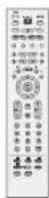
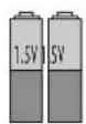
Batterie Remote Control Power Cord
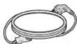
37LC2D*/42LC2D* /42PC1DG/50PC1D only

Polishing Cloth Polish the screen with the cloth.
- Slightly wipe stained spot on the exterior only with the polishing cloth for the product exterior if there is stain or fingerprint on surface of the exterior.
* Do not wipe roughly when removing stain. Please be cautions of that excessive power may cause scratch or discoloration.
For 42PC1D\*/50PC1D\*

2-Wall brackets

2-eye-bolts

2- Bolts
(Refer to p.13)
For 60PC1D\*

2-TV Brackets,
2-Wall Brackets

4-bolts

4-Ring Spacer
For 32LC2D\*/37LC2D\*/42LC2D\*

2-TV Bracket Bolts

2-TV Brackets,
2-Wall Brackets

Cable Management (Refer to p.15)

Twister Holder
Arrange the wires
with the twister holder.
32LC2D* only

4-bolts for stand assembly
See below for detail information.
(Refer to p.12)
INTRODUCTION
CONTROLS
■ Here shown may be somewhat different from your TV.
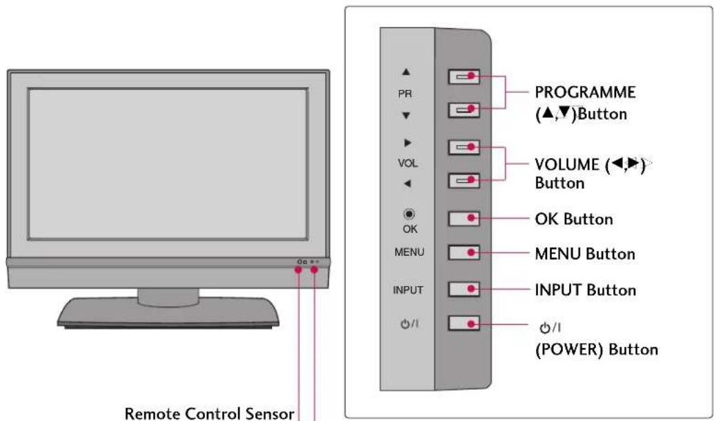
Front Panel Controls
This is a representation of the front panel of model 42PC1D*, 50PC1D*, 60PC1D*.

text_image
Remote Control Sensor Power Standby Indicator Illuminates red in stand-by mode. When the TV is turned on, the indicator blinks white and then illuminates white before the picture is displayed.CONNECTION OPTIONS
This manual explains the features available on the 42PC1D*, 50PC1D*, 60PC1D*.
■ Here shown may be somewhat different from your TV.
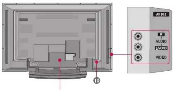
Back Connection Panel
text_image
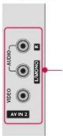
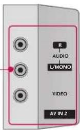
AV IN 2 AUDIO MOND VIDEO 10AUDIO Input
Connections are available for listening to stereo sound from an external device.
VIDEO Input
Connects the video signal from a video device.
text_image
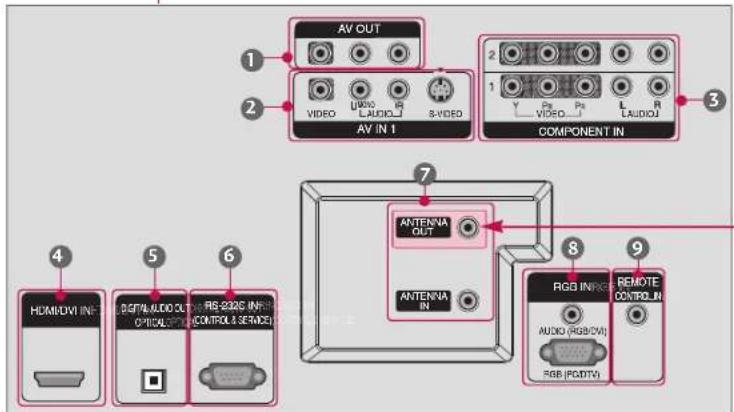
AV OUT VIDEO AV IN T AV OUT VIDEO AV IN T 8-VI/DVD COMPONENT IN 1 2 3 4 5 6 ANTENNA OUT ANTENNA IN 8 9 RGB IN VDD AUDIO (RGB/CVI) RGB (RGB/CVI) REMOTE CONTROL IN HOMO/OVI IN- Digital/Audio OUT OPTICAL/SPIN CONTROLS SERVICE\* ANTENNA OUT
This jack is not available for all models.
1 AV OUT
Connect a second TV or monitor.
② AV (Audio/Video) IN 1
Connect audio/video output from an externa device to these jacks.
S-VIDEO
Connect S-Video out from an S-VIDEO device.
3 COMPONENT IN
Connect a component video/audio device to these jacks.
4 HDMI/DVI IN
Connect a HDMI signal.
Or DVI(VIDEO)signal to the this port with a HDMI to DVI cable.
5 DIGITAL AUDIO OUT OPTICAL
Connect digital audio from various types of equipment. Note: In standby mode, these ports do not work.
6 RS-232C IN (CONTROL & SERVICE) PORT
Connect to the RS-232C port on a PC.
⑦ ANTENNA IN / ANTENNA OUT
Connect cable signals to this jack.
8 RGB/AUDIO IN
Connect the output from a setup box or PC to the appropriate input port.
9 Remote Control Port
Connect your wired remote control.
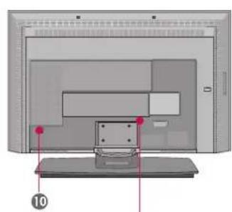
10 Power Cord Socket
For operation with AC power.
Caution: Never attempt to operate the TV on DC power.
INTRODUCTION
CONTROLS
This is a front panel of 32LC2D*, 37LC2D*, 42LC2D*.
■ Here shown may be somewhat different from your TV.
Front Panel Controls
text_image
Remote Control Sensor PROGRAMME (▲,▼)Button VOLUME (◄,►) Button OK Button MENU Button INPUT Button ○/1 (POWER) ButtonPower Standby Indicator
Illuminates red in standby mode.
When the TV is turned on, the indicator
blinks white and then illuminates white
before the picture is displayed.
CONNECTION OPTIONS
This is the back panel of 32LC2D*, 37LC2D*, 42LC2D*.
■ Here shown may be somewhat different from your TV.
Back Connection Panel
natural_image
Diagram of a computer monitor with labeled components and red markers, no readable text or symbols present37/42LC2D*
AUDIO Input
Connections are available for listening to stereo sound from an external device.
VIDEO Input
Connects the video signal from a video device.
32LC2D*
text_image
R AUDIO L/MONO VIDEO AV IN 2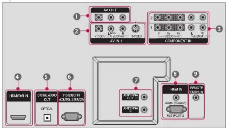
text_image
AV OUT VIDEO AV IN 1 COMPONENT IN HDAMDVIN DIGITAL AUDIO OUT OPTICAL FIB-232C IN (COMPUT. SERVICE) ANTENNA OUT ANTENNA IN RGB IN AUDIO (RGB/TV) RGB (PCOTV) REMOTE CONTROL IN① AV OUT
Connect a second TV or monitor.
② AV (Audio/Video) IN 1
Connect audio/video output from an externa device to these jacks.
S-VIDEO
Connect S-Video out from an S-VIDEO device.
3 COMPONENT IN
Connect a component video/audio device to these jacks.
4 HDMI/DVI IN
Connect a HDMI signal.
Or DVI(VIDEO)signal to the this port with a HDMI to DVI cable.
5 DIGITAL AUDIO OUT
Connect digital audio from various types of
equipment. Note: In standby mode, these ports do not work.
6 RS-232C IN (CONTROL & SERVICE) PORT
Connect to the RS-232C port on a PC.
⑦ ANTENNA IN / ANTENNA OUT
Connect cable signals to this jack.
8 RGB/AUDIO IN
Connect the output from a settop box or PC to the appropriate input port.
9 Remote Control Port
Connect your wired remote control.
10 Power Cord Socket
For operation with AC power.
Caution: Never attempt to operate the TV on DC power.
INTRODUCTION
REMOTE CONTROL KEY FUNCTIONS
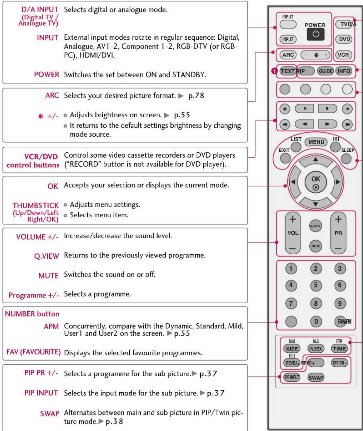
When using the remote control, aim it at the remote control sensor on the TV.
text_image
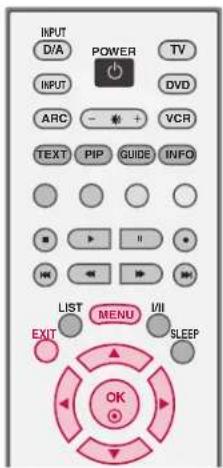
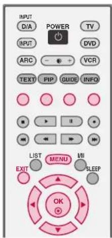
D/A INPUT Selects digital or analogue mode. (Digital TV/ Analogue TV) INPUT External input modes rotate in regular sequence: Digital, Analogue, AV1-2, Component 1-2, RGB-DTV (or RGB- PC), HDMI/DVI. POWER Switches the set between ON and STANDBY. ARC Selects your desired picture format. ▶ p.78 +/- • Adjusts brightness on screen. ▶ p.55 • It returns to the default settings brightness by changing mode source. VCR/DVD Control buttons Control some video cassette recorders or DVD players ("RECORD" button is not available for DVD player). OK Accepts your selection or displays the current mode. THUMBSTICK • Adjusts menu settings. (Up/Down/Left Right/OK) • Selects menu item. VOLUME +/- Increase/decrease the sound level. Q.VIEW Returns to the previously viewed programme. MUTE Switches the sound on or off. Programme +/- Selects a programme. NUMBER button APM Concurrently, compare with the Dynamic, Standard, Mild, User1 and User2 on the screen. ▶ p.55 FAV (FAVOURITE) Displays the selected favourite programmes. PIP PR +/- Selects a programme for the sub picture. ▶ p.37 PIP INPUT Selects the input mode for the sub picture. ▶ p.37 SWAP Alternates between main and sub picture in PIP/Twin pic- ture mode. ▶ p.38TV, DVD, VCR, Selects the remote operating mode: TV, VCR, DVD. Select other operating modes, for the remote to operate external devices.
PIP Switches to PIP, POP and Twin picture modes or off mode.▶ p.36-39
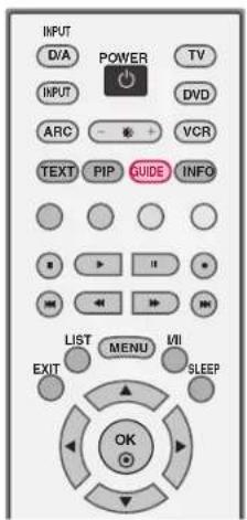
GUIDE Shows a programme schedule. ▶ p.42
INFO Shows the present screen information.
COLOURE They are used as per the indications or functions displayed on the TV screen in the case of Button Text displays (Teletext, EPG) and programme edit.
EXIT Returns to TV viewing from any menu.
LIST Displays the programme table. ▶ p.51
MENU Selects a menu.
I/II Selects the sound output or the audio mode. ▶ p.69
SLEEP Sets the sleep timer. ▶ p.73
① TELETEXT These buttons are used for teletext.
BUTTONS Text button is used to enable teletext services while other buttons are for teletext functions. * For further details, see the 'Teletext' section. ▶ p.40-41
Installing Batteries Remote control effective range
natural_image
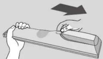
Illustration of hands using a tool to lift a rectangular object, with an arrow indicating downward motion (no text or symbols)- Open the battery compartment cover on the back side and install the batteries matching correct polarity (+with +,-with -).
- Install two 1.5V AA batteries. Don't mix old or used batteries with new ones.
- Close cover.
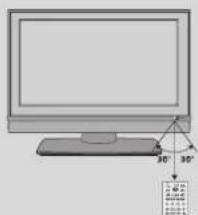
text_image
Diagram showing a computer monitor with a 30-degree angle and a small labeled diagram below it.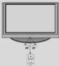
text_image
30° 10° 10°■ Use a remote control up to 7 meters distance and 30 degree (left/right) within the receiving unit scope.
■ Dispose of used batteries in a recycle bin to preserve environment.
INSTALLATION
STAND INSTALLATION(FOR 32LC2D\*)
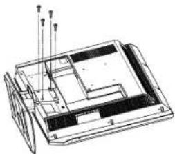
1 Carefully place the product screen side down on a cushioned surface that will protect product and screen from damage.
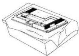
natural_image
Technical line drawing of a mechanical component or housing (no text or symbols)2 Place the hook of the stand in the back of the product as shown.
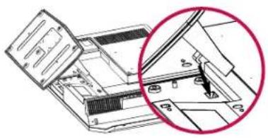
natural_image
Technical diagram of a mechanical assembly with a magnified inset showing internal components (no text or symbols)3 Install the 4 bolts provided securely, in the back of the product.
natural_image
Technical line drawing of a mechanical assembly with no visible text or symbolsThis manual explains the features available on the 42PC1D*, 50PC1D*, 60PC1D*.
■ Here shown may be somewhat different from your TV.
text_image
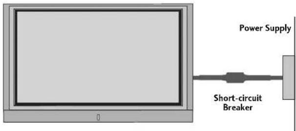
Power Supply Short-circuit BreakerGROUNDING
Ensure that you connect the earth ground wire to prevent possible electric shock. If grounding methods are not possible, have a qualified electrician install a separate circuit breaker.
Do not try to ground the unit by connecting it to telephone wires, lightening rods, or gas pipes.
STAND INSTALLATION (FOR 42PC1D\*)
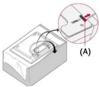
1 Place the set with the screen facing down on a cushion or soft cloth as shown.
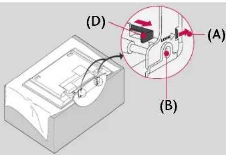
Before unfolding the stand, please make sure two locks (A) on the bottom of the stand push outward.
text_image
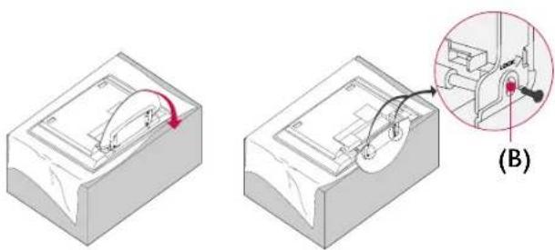
(A)Pull the stand out as shown.
After unfolding the stand, please insert and tighten the screws (provided as parts of the product) in the holes (B) on the bottom of the stand.
natural_image
Two technical diagrams showing a mechanical assembly with a red arrow indicating rotation and a magnified inset of a component (B), no text or symbols present.3 When connecting cables to the set, Do not disengage the lock (C).
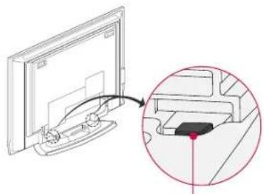
This may cause the set to fall, causing serious bodily injury and serious damage to the set.
natural_image
Diagram showing a computer monitor with an attached cable, and a magnified inset highlighting a cable detail (no text or symbols present)(C)
NOTE
Image shown here may be slightly different from your set.
When closing the stand for storage
■ First remove the screws in the holes (B) on the bottom of the stand. And then pull two Hooks (D) of the stand bottom and fold the stand into the back of the set.
■ After folding, push the two Locks (A) of the stand bottom outward.
text_image
(D) (A) (B)INSTALLATION
WIRE ARRANGEMENT
This function explains the features available on the 50PC1D*.
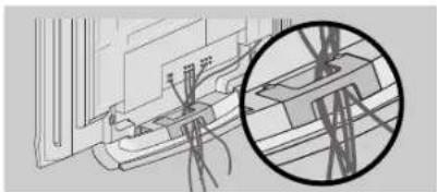
1 Hold the CABLE MANAGEMENT with both hands and pull it backward as shown.
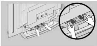
natural_image
Illustration of hands operating a device with a magnified inset showing the process (no text or symbols visible)2 Connect the cables as necessary. To connect an additional equipment, see the Connections & Setup section.
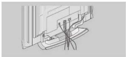
natural_image
Line drawing of a small boat docked at a window with visible chairs and legs (no text or symbols)3 Install the CABLE MANAGEMENT as shown.
natural_image
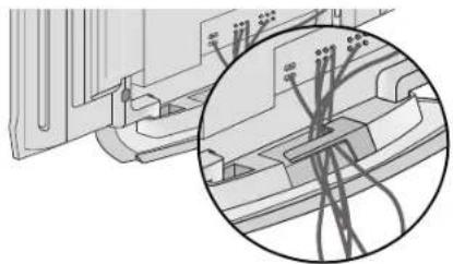
Technical line drawing of a mechanical assembly with a magnified inset showing internal components (no text or symbols)This function explains the features available on the 42PC1D*, 60PC1D*.
1 Connect the cables as necessary. After connecting the cables neatly, arrange the cables to the Cable Holder. To connect an additional equipment, see the Connections & Setup section.
2 Arrange the cable as shown.
natural_image
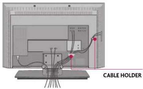
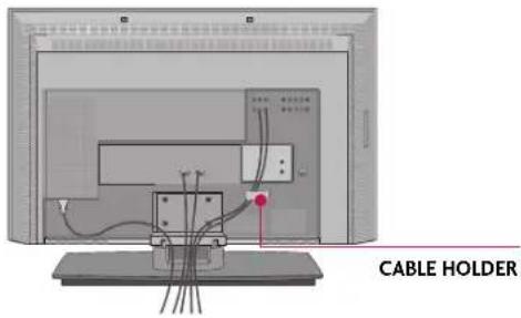
Technical diagram showing a mechanical assembly with a magnified inset of internal components (no text or symbols visible)This function explains the features available on the 32LC2D*, 37LC2D*, 42LC2D*.
1 Connect the cables as necessary.
After connecting the cables neatly, arrange the cables to the Cable Holder. To connect an additional equipment, see the Connections & Setup section.
37LC2D*, 42LC2D*
text_image
CABLE HOLDER32LC2D*
text_image
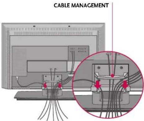
CABLE HOLDER2 Install the CABLE MANAGEMENT as shown.
text_image
CABLE MANAGEMENTHow to remove the CABLE MANAGEMENT
▶ Hold the CABLE MANAGEMENT with both hands and pull it upward.
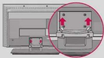
natural_image
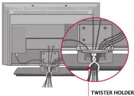
Diagram showing a computer monitor with an open panel and a magnified view of the screen (no text or symbols present)3 Bundle the cables using the supplied twister holder.
text_image
TWISTER HOLDERNOTE
Do not hold the CABLE MANAGEMENT when moving the product.
- If the product is dropped, you may be injured or the product may be broken.
INSTALLATION
ATTACHING THE TV TO A WALL
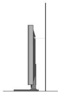
Set it up close to the wall so the product doesn't fall over when it is pushed backwards.
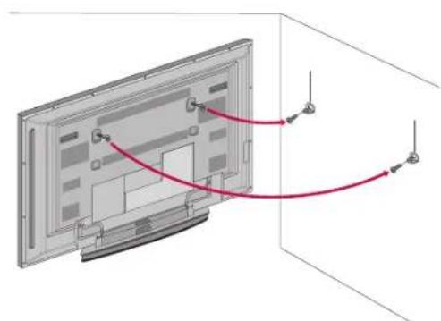
The instructions shown below is a safer way to set up the product, which is to fix it on the wall so the product doesn't fall over when it is pulled in the forward direction. It will prevent the product from falling forward and hurting people. It will also prevent the product from damage caused by fall. Please make sure that children don't climb on or hang from the product.
natural_image
Diagram of a flat-screen TV with cable routing arrows indicating cable movement (no text or symbols)32/37/42LC2D*42/50/60PC1D*

text_image
Diagram showing cable routing between a computer monitor and two connected devices with red arrows indicating direction■ Insert the eye-bolts (or TV brackets and bolts) to tighten the product to the wall as shown in the picture.
* If your product has the bolts in the eye-bolts position before inserting the eye-bolts, loosen the bolts. Insert the eye-bolts and tighten them securely in the upper holes.
Secure the wall brackets with the bolts (not provided as parts of the product, must purchase separately) on the wall. Match the height of the bracket that is mounted on the wall to the holes in the product.
Ensure the eye-bolts or brackets are tightened securely.
natural_image
Side view of a modern vertical monitor or screen mounted on a stand, with no visible text or symbols.■ Use a sturdy rope (must be purchased separately) to secure the TV. It is safer to tie the rope so it runs horizontally between the wall and the TV.
DESKTOP PEDESTAL INSTALLATION
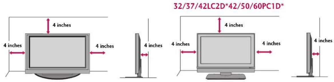
For proper ventilation, allow a clearance of 4 inches on each side from the wall.
text_image
4 inches 4 inches 4 inches 4 inches 32/37/42LC2D*42/50/60PC1D* 4 inches 4 inches 4 inches 4 inches
CAUTION
▶ Ensure adequate ventilation by following the clearance recommendations.
SWIVEL STAND
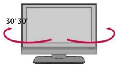
This function explains the features available on the 42LC2D*.
text_image
30° 30°The TV can be conveniently swivelled on its stand 30^ to the left or right to provide the optimum viewing angle.
CONNECTIONS & SETUP
'Connections & Setup' part explains the features available on the 32/37/42LC2D*.
ANTENNA CONNECTION
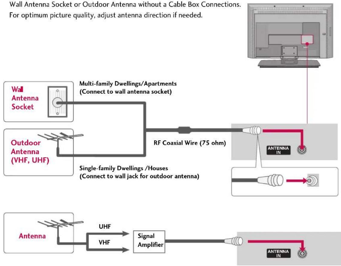
Wall Antenna Socket or Outdoor Antenna without a Cable Box Connections. For optimum picture quality, adjust antenna direction if needed.
flowchart
graph TD
    A["Wall Antenna Socket"] --> B["Multi-family Dwellings/Apartments (Connect to wall antenna socket)"]
    C["Outdoor Antenna (VHF, UHF)"] --> D["RF Coaxial Wire (75 ohm)"]
    E["Antenna"] --> F["UHF"]
    E --> G["VHF"]
    F --> H["Signal Amplifier"]
    G --> H
    H --> I["Antenna IN"]
    style A fill:#f9f,stroke:#333
    style C fill:#f9f,stroke:#333
    style E fill:#f9f,stroke:#333
    style I fill:#ccf,stroke:#333
■ To improve the picture quality in a poor signal area, please purchase a signal amplifier and install properly.
If the antenna needs to be split for two TV's, install a 2-Way Signal Splitter.
■ If the antenna is not installed properly, contact your dealer for assistance.
NOTE
The TV will let you know when the analogue, cable, and digital programme scans are complete.
ANTENNA LOOP THROUGH SOCKET
- 42PC1DV, 32/37/42LC2D only
The TV has a special signal output capability which allows you to hook up the second TV.
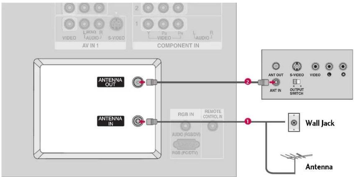
text_image
AV IN 1 COMPONENT IN ANTENNA OUT ANTENNA IN RGB IN REMOTE CONTROL IN AUDIO (RGB/DVI) RGB (PC/DTV) ANT OUT S-VIDEO VIDEO L R ANT IN OUTPUT SWITCH Wall Jack Antenna1. How to connect
1 Connect the wall antenna socket or outdoor antenna to the TV's ANTENNA IN socket.
2 Connect a second TV's antenna socket to the TV's ANTENNA OUT socket.
NOTE
In standby mode, these ports do not work.
CONNECTIONS & SETUP
HDSTB SETUP
This TV can receive Digital Over-the-air/Cable signals without an external digital set-top box. However, if you do receive digital signals from a digital set-top box or other digital external device, refer to the figure as shown below.
This TV supports HDCP (High-bandwidth Digital Contents Protection) protocol for Digital Contents (480p,720p,1080i).
When connecting Component cable
1. How to connect
1 Connect the video outputs (Y, PB, PR) of the digital set top box to the COMPONENT IN VIDEO 1 jacks on the set. Match the jack colors (Y = green, PB = blue, and PR = red)
2 Connect the audio output of the digital set-top box to the COMPONENT IN AUDIO 1 jacks on the set.
2. How to use
■ Turn on the digital set-top box.
(Refer to the owner's manual for the digital set-top box)
■ Select Component 1 input source with using the INPUT button on the remote control.
■ If connected to COMPONENT IN 2 input, select
Component 2 input source.
| Signal | Component 1/2 | RGB-DTV, HDMI |
| 480i | Yes | No |
| 480p | Yes | Yes |
| 576i | Yes | No |
| 576p | Yes | Yes |
| 720p | Yes | Yes |
| 1080i | Yes | Yes |
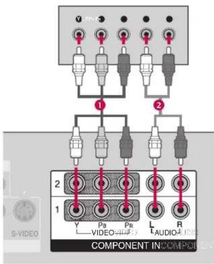
text_image
V-IP 1 2 COMPONENT INCOMPONENT Y P8 PR L R VIDEO AUDIO L AUDIOWhen connecting D-sub 15pin cable
1. How to connect
1 Connect the RGB output of the digital set-top box to the RGB (PC/DTV) jack on the set.
2 Connect the audio outputs of the set-top box to the AUDIO(RGB/DVI) jack on the set.
2. How to use
■ Turn on the digital set-top box.
(Refer to the owner's manual for the digital set-top box)
■ Select RGB-DTV input source with using the INPUT button on the remote control.
When connecting HDMI cable
1. How to connect
1 Connect the digital set-top box toHDMI/DVI IN jack on the set.
2 No separated audio connection is necessary.
2. How to use
■ Turn on the digital set-top box.
(Refer to the owner's manual for the digital set-top box.)
■ Select HDMI/DVI input source with using the INPUT button on the remote control.
NOTE
If the digital set-top box supports Auto HDMI function, the output resolution of the source device will be automatically set to 1280x720p.
If the digital set-top box player does not support Auto HDMI, you need to set the output resolution appropriately. To get the best picture quality, adjust the output resolution of the source device to 1280x720p.
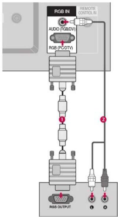
text_image
RGB IN AUDIO (RGB/DV) RGB (PC/DTV) REMOTE CONTROL IN 1 2 RGB OUTPUT L R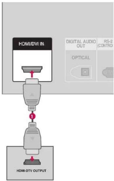
flowchart
graph TD
    A["HDMI-DVI IN"] --> B["1"]
    B --> C["HDMI-DTV OUTPUT"]
    D["DIGITAL AUDIO OUT"] --> E["OPTICAL"]
    F["RS-2 (CONTROL)"] --> G["Output"]
CONNECTIONS & SETUP
When connecting HDMI to DVI cable
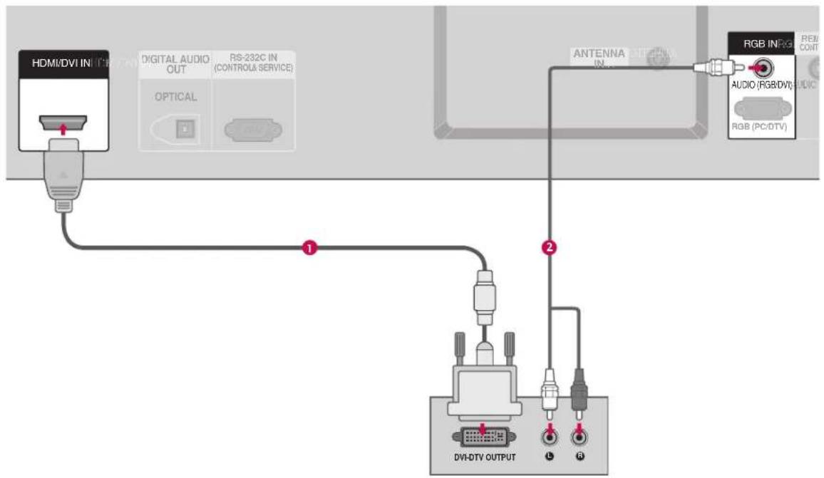
flowchart
graph TD
    A["HDMI/DVI IN"] --> B["1"]
    C["Digital Audio OUT"] --> B
    D["RS-232C IN (CONTROL & SERVICE)"] --> B
    E["OPTICAL"] --> B
    F["ANTENNA IN"] --> G["2"]
    H["RGB IN"] --> I["RGB (PC/DTV)"]
    J["AUDIO (RGB/DVI)"] --> K["2"]
    L["DVI-DTV OUTPUT"] --> M["1"]
    N["4"] --> O["5"]
1. How to connect
1 Connect the DVI output of the digital set-top box to the HDMI /DVI IN jack on the set.
2 Connect the audio output of the digital set-top box to the AUDIO(RGB/DVI) jack on the set.
2. How to use
■ Turn on the digital set-top box. (Refer to the owner's manual for the digital set-top box.)
■ Select HDMI/DVI input source with using the INPUT button on the remote control.
VCR SETUP
■ To avoid picture noise (interference), leave an adequate distance between the VCR and TV.
If the 4:3 picture format is used; the fixed images on the sides of the screen may remain visible on the screen. This phenomenon is common to all manufactures and in consequence the manufactures warranty does not cover the product bearing this phenomenon.
When connecting with an antenna
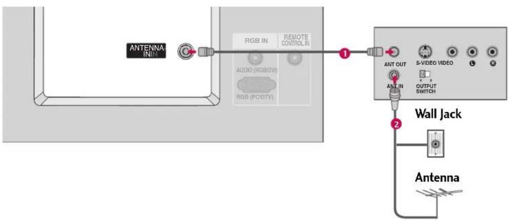
text_image
ANTENNA IN RGB IN REMOTE CONTROL IN AUDIO (RGB/0V) RGB (PC/DTV) 1 ANT OUT S-VIDEO VIDEO L R ANT IN OUTPUT SWITCH 2 Wall Jack Antenna1. How to connect
1 Connect the RF antenna out socket of the VCR to the Antenna socket on the set.
2 Connect the antenna cable to the RF antenna in socket of the VCR.
2. How to use
■ Set VCR output switch to 3 or 4 and then tune TV to the same programme number.
- Insert a video tape into the VCR and press PLAY on the VCR. (Refer to the VCR owner's manual.)
CONNECTIONS & SETUP
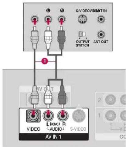
When connecting with a RCA cable
1. How to connect
1 Connect the AUDIO/VIDEO jacks between TV and VCR. Match the jack colors(Video = yellow, Audio Left = white, and Audio Right = red)
2. How to use
- Insert a video tape into the VCR and press PLAY on the VCR. (Refer to the VCR owner's manual.)
■ Select AV1 input source with using the INPUT button on the remote control.
■ If connected to AV IN2, select AV2 input source.
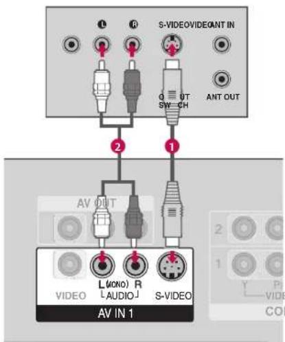
When connecting with an S-Video cable
1. How to connect
1 Connect the S-VIDEO output of the VCR to theS-VIDEO input on the set. The picture quality is improved; compared to normal composite (RCA cable) input.
2 Connect the audio outputs of the VCR to the AUDIO input jacks on the set.
2. How to use
- Insert a video tape into the VCR and press PLAY on the VCR. (Refer to the VCR owner's manual.)
■ SelectAV1 input source with using the INPUTbutton on the remote control.
NOTE
The picture quality is improved: ; compared to normal composite (RCA cable) input.
text_image
S-VIDEOVIDEN IN OUTPUT SWITCH ANT OUT AV OUT L(ANO) R L-AUDIO J S-VIDEO AV IN 1NOTE
If you have a mono VCR, connect the audio cable from the VCR to the AUDIO L(MONO) jack of the set.
text_image
L R S-VIDEOVIDEANT IN Q OT SW CH ANT OUT 2 1 AV OUT L(ONO) R L(AUDIO)J S-VIDEO AV IN 1 VIDEO Y P VIDEO COICAUTION
Do not connect to both Video and S-Video at the same time. In the event that you connect both Video and the S-Video cables, only the S-Video will work.
AV OUT SETUP
The TV has a special signal output capability which allows you to hook up the second TV or monitor.
1. How to connect

Connect the second TV or monitor to the TV's AV OUT jacks.

See the Operating Manual of the second TV or monitor for further details regarding that device's input settings.

NOTE
Digital, Component1-2, RGB-PC/RGB-DTV, HDMI/DVI input sources cannot be used for AV out.
We recommend to use the AV OUT jacks for VCR recording.
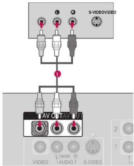
text_image
L R S-VIDEOVIDEO 1 AV OUT OUT VIDEO L/MON R S-VIDEO 2 1 YCONNECTIONS & SETUP
DIGITAL AUDIO OUTPUT
Send the TV's audio to external audio equipment via the Digital Audio Output (Optical) port.
1. How to connect
1 Connect one end of an optical cable to the TV Digital Audio (Optical) Output port.
2 Connect the other end of the optical cable to the digital audio (optical) input on the audio equipment.
3 Set the "TV Speaker option - Off" in the AUDIO menu. (▶p.68). See the external audio equipment instruction manual for operation.
NOTE
▶ When connecting with external audio equipments, such as amplifiers or speakers, please turn the TV speakers off. (▶ p.68)
CAUTION
Do not look into the optical output port. Looking at the laser beam may damage your vision.
i.e) 32/37/42LC2D*
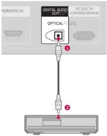
text_image
HDMI/DVI IN DIGITAL AUDIO OUTPUT PS-232C IN (CONTROLS & SERVICE) OPTICAL TICEL ① ②i.e)42PC1D*, 50PC1D*, 60PC1D*
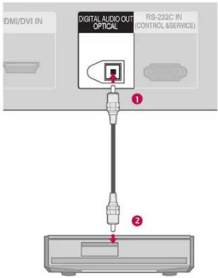
text_image
DMI/DVI IN DIGITAL AUDIO OUT OPTICAL RS-232C IN (CONTROL &SERVICE) ① ②EXTERNAL A/V SOURCE SETUP
1. How to connect
1 Connect the AUDIO/VIDEO jacks between TV and external equipment. Match the jack colors.(Video = yellow, Audio Left = white, and Audio Right = red)
2. How to use
■ Select AV1 input source with using the INPUT button on the remote control.
■ If connected to AV IN2 input, select AV2 input source.
■ Operate the corresponding external equipment.
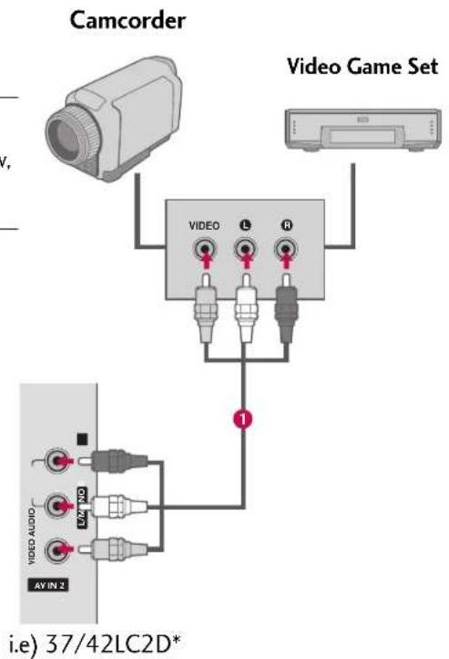
text_image
Camcorder Video Game Set VIDEO L R 1 VIDEO AUDIO MYND AY IN 2 i.e) 37/42LC2D*CONNECTIONS & SETUP
DVD SETUP
When connecting Component cable
1. How to connect
1 Connect the video outputs (Y, PB, PR) of the DVD to the COMPONENT IN VIDEO1 jacks on the set. Match the jack colors (Y = green, PB = blue, and PR = red).
2 Connect the audio outputs of the DVD to the COMPONENT IN AUDIO1 jacks on the set.
2. How to use
■ Turn on the DVD player, insert a DVD.
■ Select Component 1 input source with using the INPUT button on the remote control.
■ If connected to COMPONENT IN 2 input, select Component 2 input source.
- Refer to the DVD player's manual for operating instructions.
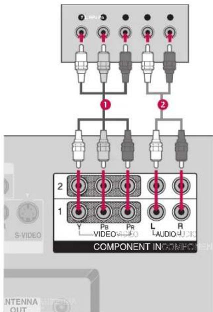
text_image
V N 1 2 2 1 Y Pb Pr L R VIDEO AUDIO TAUDIO COMPONENT IN COMPOEN S-VIDEO ANTENNA OUTComponent Input ports
To get better picture quality, connect a DVD player to the component input ports as shown below.
| Component ports on the TV | Y | P_B | P_R |
| Video output portson DVD player | Y | Pb | Pr |
| Y | B-Y | R-Y | |
| Y | Cb | Cr | |
| Y | Pb | Pr |
When connecting with an S-Video cable
1. How to connect
1 Connect the S-VIDEO output of the DVD to the S-VIDEO input on the set.
2 Connect the audio outputs of the DVD to the AUDIO input jacks on the set.
2. How to use
■ Turn on the DVD player, insert a DVD.
■ Select AV1 input source with using the INPUT button on the remote control.
■ Refer to the DVD player's manual for operating instructions.
When connecting HDMI cable
1. How to connect
1 Connect the HDMI output of the DVD to the HDMI/DVI IN jack on the set.
2 No separated audio connection is necessary.
2. How to use
■ Select HDMI/DVI input source with using the INPUT button on the remote control.
■ Refer to the DVD player's manual for operating instructions.
NOTE
If the DVD supports Auto HDMI function, the DVD output resolution will be automatically set to 1280x720p.
If the DVD does not support Auto HDMI, you need to set the output resolution appropriately.
To get the best picture quality, adjust the output resolution of the DVD to 1280x720p.
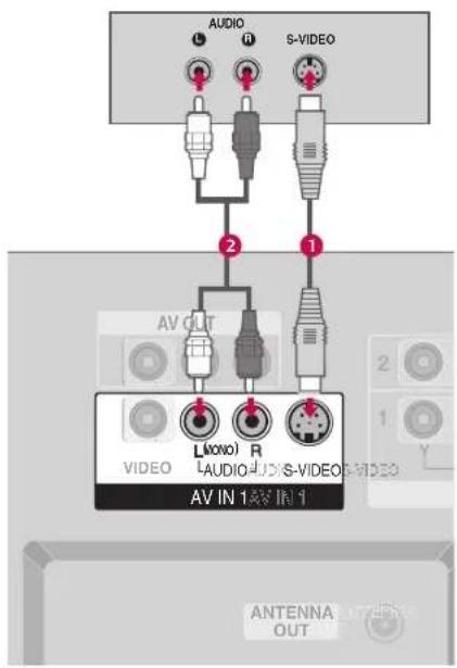
text_image
AUDIO S-VIDEO AV OUT L(AXO) R AUDIO S-VIDEO AV IN 1AV IN 1 VIDEO ANTENNA OUT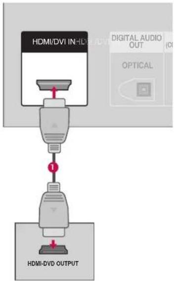
flowchart
graph TD
    A["HDMI/DVI IN-HD"] --> B["1"]
    B --> C["HDMI-DVD OUTPUT"]
    D["DIGITAL AUDIO OUT"] --> E["(CH)"]
    F["OPTICAL"] --> G["Switch"]
CONNECTIONS & SETUP
PC SETUP
This TV provides Plug and Play capability, meaning that the PC adjusts automatically to the TV's settings. The TV perceives 640x480, 60Hz as DTV 480p based on the PC graphic card. If necessary, change the screen scanning rate for the graphic card accordingly.
When connecting D-sub 15pin cable
1. How to connect
1 Connect the RGB output of the PC to the RGB (PC/DTV)jack on the set.
2 Connect the PC audio output to the AUDIO (RGB/DVI) ack on the set.
2. How to use
■ Turn on the PC and the set.
■ Select RGB-PC input source in main input option of Special menu.(▶ p.75)
■ Once you select RGB-PC in main input option of Special menu, INPUTbutton is also available for this purpose.
NOTE
▶ Check the image on your TV. There may be noise associated with the resolution, vertical pattern, contrast or brightness in PC mode. If noise is present, change the PC output to another resolution, change the refresh rate to another rate or adjust the brightness and contrast on the VIDEO menu until the picture is clear. If the refresh rate of the PC graphic card can not be changed, change the PC graphic card or consult the manufacturer of the PC graphic card.
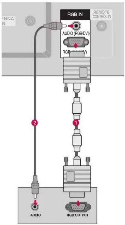
text_image
ENNA N RGB IN AUDIO (RGB/DVI) RGB REMOTE CONTROL IN 2 1 AUDIO RGB OUTPUTWhen connecting HDMI to DVI cable
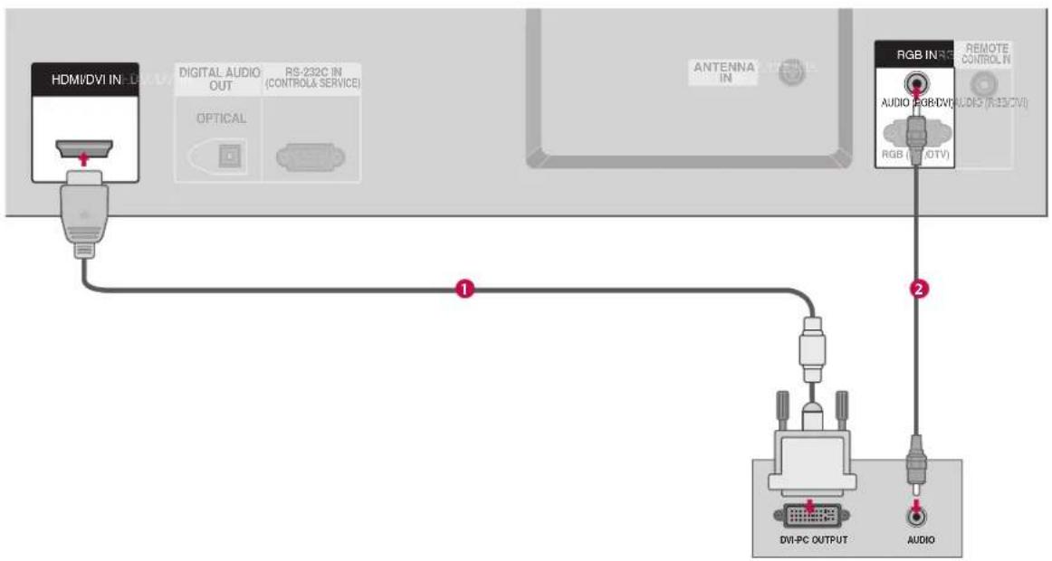
flowchart
graph TD
    A["HDMI/DVI IN"] -->|USB| B["Digital Audio OUT"]
    B --> C["RS-232C IN (CONTROL & SERVICE)"]
    C --> D["OPTICAL"]
    D --> E["Antenna IN"]
    E --> F["RGB IN RGB REMOTE CONTROL IN"]
    F --> G["RGB (R130TV)"]
    G --> H["AVIO FOR/VO AUDIO (R130TV)"]
    H --> I["DVI-PC OUTPUT"]
    I --> J["AUDIO"]
1. How to connect
1 Connect the DVI output of the PC to the HDMI /DVI IN jack on the set.
2 Connect the PC audio output to the AUDIO (RGB/DVI) jack on the set.
2. How to use
■ Turn on the PC and the set
■ Select HDMI/DVI input source with using the INPUT button on the remote control.
NOTE
If the PC has a DVI output and no HDMI output, a separated audio connection is necessary.
If the PC does not support Auto DVI, you need to set the output resolution appropriately. To get the best picture quality, adjust the output resolution of PC graphics card's output resolution to 1024x768, 60Hz.
CONNECTIONS & SETUP
NOTES
To get the the best picture quality, adjust the PC graphics card to 1024x768, 60Hz.
▶ Depending on the graphics card, DOS mode may not work if a HDMI to DVI Cable is in use.
When Source Devices are connected with HDMI/DVI Input, the output PC Resolution(VGA, SVGA, XGA), Position and Size may not fit on the Screen. As shown in the picture below, press the ADJUST button to adjust the screen Position of the TV SET and contact a PC graphics card service center.
When Source Devices connected with HDMI/DVI Input, output TV SET Resolution (480p, 720p, 1080i) and TV SET Display fit EIA/CEA-861-B
Supported Display Specifications (RGB/HDMI-PC)
| Resolution | Horizontal Vertical Frequency(KHz) Frequency(Hz) | |
| 640x350 | 31.468 | 70.09 |
| 640x480 | 31.469 | 59.94 |
| 37.861 | 72.80 | |
| 37.500 | 75.00 | |
| 800x600 | 35.156 | 56.25 |
| 37.879 | 60.31 | |
| 48.077 | 72.18 | |
| 46.875 | 75.00 | |
| 1024x768 | 48.363 | 60.00 |
| 56.476 | 70.06 | |
| 60.023 | 75.02 | |
* RGB-PC mode only: 640x350
Specification to Screen. If not, refer to the Manual of HDMI/DVI Source Devices or contact your service center.
If the HDMI/DVI Source Device is not connected to the Cable or if there is a poor cable connection, "No signal" is displayed in the HDMI/DVI Input. In this case, that Video Resolution is not supported. If "Invalid Format" is displayed, refer to the Source Device manual or contact your service center.
Avoid keeping a fixed image on the screen for a long period of time. The fixed image may become permanently imprinted on the screen.
The synchronization input form for Horizontal and Vertical frequencies is separate.
Supported Display Specifications (RGB/HDMI-DTV)
| Resolution | Horizontal Vertical Frequency(KHz) | Frequency(Hz) |
| 720x576 | 31.25 | 50.00 |
| 720x480 | 31.47 | 59.94 |
| 31.50 | 60.00 | |
| 1280x720 | 37.50 | 50.00 |
| 44.96 | 59.94 | |
| 45.00 | 60.00 | |
| 1920x1080 | 28.125 | 50.00 |
| 33.72 | 59.94 | |
| 33.75 | 60.00 |
Screen Setup for PC mode
Overview
This function works in the following mode:
Component1, Component2, RGB-PC, RGB-DTV, or HDMI/DVI.
Note: Some signal from some graphics boards may not function properly. If the results are unsatisfactory, adjust your monitor's position, size and phase manually.
Adjustment for screen Position, Clock, Phase
1 Press the ○○ button and then use ▲ or ▼ button to select Position, Clock, or Phase.
2 Press the ▶ button and then use ▲ ▼ ◀ ▶ button to make appropriate adjustments.
■ The Phase adjustment range is -32 \~ +32
The Phase only works in Component 1-2, RGB-PC and RGB-DTV mode.
■ The Clock adjustment range is -50 \~ +50.
The Clock only works in RGB-PC mode.
3 Press the O button.
Initializing (Reset to original factory values)
To initialize the adjusted values
This function allows you to return to the good picture reproduction programmed at the factory and cannot be change.
1 Press the O O button and then use ▲ or ▼ button to select Reset.
2 Press the ▶ button and then use ◀ or ▶ button to select Yes.
3 Press the O OK button.
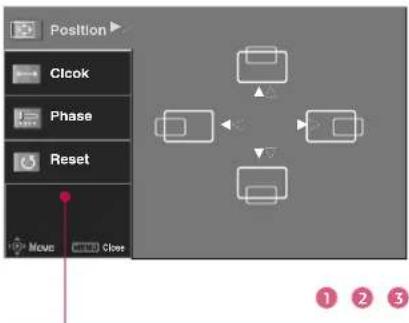
text_image
Position Clock Phase Reset Move Close 1 2 3Position This function is to adjust picture to left/right and up/down as you prefer.
Clock This function is to minimize any vertical bars or stripes visible on the screen background. And the horizontal screen size will also change.
Phase This function allows you to remove any horizontal noise and clear or sharpen the image of characters. In HDMI/DVI-PC mode, PHASE is not available.
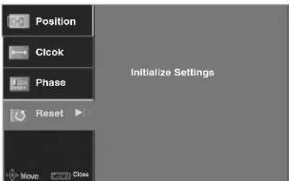
text_image
Position Clock Phase Reset Initialize Settings Move Close
BASIC OPERATION
TURNING THE TV ON
If your TV will be turned on, you will be able to use its features.
1 Ensure the power cord is connected correctly. When connected to power the TV switches to standby mode.
In standby mode, press the ,∅/1 INPUT, PR + / --button on the TV or press the POWER, INPUT, D/A INPUT, PPR + / -, Number (0\~9) button on the remote control.
2 Select the viewing source by using the INPUT button on the remote control.
■ This TV is programmed to remember which mode it was last set to, even if you turn the TV off.
3 When finished using the TV, press the POWER button on the remote control. The TV reverts to standby mode.
NOTE
If you intend to be away on vacation, disconnect the power plug from the wall power outlet.
INITIALIZING SETUP
If the OSD (On Screen Display) is displayed on the screen as figure 1 after turning on the set, you can adjust the Auto Programme tuning, Time Zone selection or Password setting.
NOTE
It will automatically disappear after approx. 40 seconds unless a button is pressed.
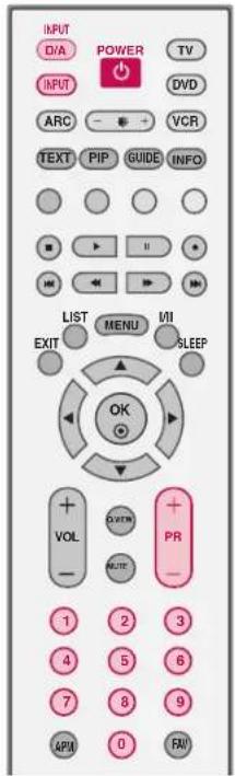
text_image
INPUT D/A POWER TV INPUT ARC VCR TEXT PIP GUIDE INFO LIST MENU MII EXIT SLEEP OK + - VOL + - OUTEN PR 1 2 3 4 5 6 7 8 9 APIA 0 RAV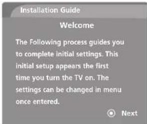
text_image
Installation Guide Welcome The following process guides you to complete initial settings. This initial setup appears the first time you turn the TV on. The settings can be changed in menu once entered.Figure 1.
VOLUME ADJUSTMENT
Adjust the volume to suit your personal preference.
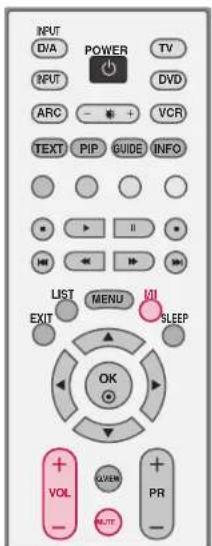
1 Press the VOL + / --button to adjust the volume.
2 If you want to switch the sound off, press the MUTE button.
You can cancel the Mute function by pressing the MUTE, I/II or VOL + / - button.
text_image
INPUT D/A POWER TV INPUT ARC - + VCR TEXT PIP GUIDE INFO LIST MENU VOL EXIT SLEEP OK + - LIVEN + - PR + -PROGRAMME SELECTION
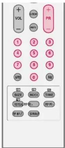
Automatically finds all programmes available through antenna or cable inputs, and stores them in memory on the programme list.
1 Press the PR + / -- or NUMBER buttons to select a programme number.
text_image
+VOL - +VIEW WRITE PR - 1 2 3 4 5 6 7 8 9 APM 0 RW SIZE INDEX TIME REVSAL RP R- RP PR FP M/F SWAPSPECIAL FUNCTIONS | PIP / POP / Twin Picture
PIP lets you view 2 different inputs (sources) on your TV screen at the same time. One source will be large, and the other source will show a smaller inset image.
Twin Picture mode splits the screen into two images, allowing two picture sources to be shown on the TV screen at the same time. Each source is given half the screen.
Watching PIP/POP/Twin Picture
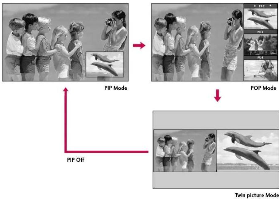
Press the PIP button to access the sub picture.
Each press of PIP changes the PIP options as shown below.
flowchart
graph TD
    A["PIP Mode"] --> B["PIP Off"]
    B --> C["Twin Picture Mode"]
    subgraph PIP Mode
        D["Black-and-white photo of children holding a camera"]
        E["Black-and-white photo of children holding a camera"]
        F["Black-and-white photo of children holding a camera"]
        G["Black-and-white photo of children holding a camera"]
        H["Black-and-white photo of children holding a camera"]
        I["Black-and-white photo of children holding a camera"]
        J["Black-and-white photo of children holding a camera"]
        K["Black-and-white photo of children holding a camera"]
        L["Black-and-white photo of children holding a camera"]
        M["Black-and-white photo of children holding a camera"]
        N["Black-and-white photo of children holding a camera"]
        O["Black-and-white photo of children holding a camera"]
        P["Black-and-white photo of children holding a camera"]
        Q["Black-and-white photo of children holding a camera"]
        R["Black-and-white photo of children holding a camera"]
        S["Black-and-white photo of children holding a camera"]
        T["Black-and-white photo of children holding a camera"]
        U["Black-and-white photo of children holding a camera"]
        V["Black-and-white photo of children holding a camera"]
        W["Black-and-white photo of children holding a camera"]
        X["Black-and-white photo of children holding a camera"]
        Y["Black-and-white photo of children holding a camera"]
        Z["Black-and-white photo of children holding a camera"]
        AA["Black-and-white photo of children holding a camera"]
        AB["Black-and-white photo of children holding a camera"]
        AC["Black-and-white photo of children holding a camera"]
        AD["Black-and-white photo of children holding a camera"]
        AE["Black-and-white photo of children holding a camera"]
        AF["Black-and-white photo of children holding a camera"]
        AG["Black-and-white photo of children holding a camera"]
        AH["Black-and-white photo of children holding a camera"]
        AI["Black-and-white photo of children holding a camera"]
        AJ["Black-and-white photo of children holding a camera"]
        AK["Black-and-white photo of children holding a camera"]
        AL["Black-and-white photo of children holding a camera"]
        AM["Black-and-white photo of children holding a camera"]
        AN["Black-and-white photo of children holding a camera"]
        AO["Black-and-white photo of children holding a camera"]
        AP["Black-and-white photo of children holding a camera"]
        AQ["Black-and-white photo of children holding a camera"]
        AR["Black-and-white photo of children holding a camera"]
        AS["Black-and-white photo of children holding a camera"]
        AT["Black-and-white photo of children holding a camera"]
        AU["Black-and-white photo of children holding a camera"]
        AV["Black-and-white photo of children holding a camera"]
        AW["Black-and-white photo of children holding a camera"]
        AX["Black-and-white photo of children holding a camera"]
        AY["Black-and-white photo of children holding a camera"]
    end
    subgraph POP Mode
        AZ["Black-and-white photo of children holding a camera"]
        BA["Black-and-white photo of children holding a camera"]
        BB["Black-and-white photo of children holding a camera"]
        BC["Black-and-white photo of children holding a camera"]
        BD["Black-and-white photo of children holding a camera"]
        BE["Black-and-white photo of children holding a camera"]
        BF["Black-and-white photo of children holding a camera"]
        BG["Black-and-white photo of children holding a camera"]
        BH["Black-and-white photo of children holding a camera"]
        BI["Black-and-white photo of children holding a camera"]
        BJ["Black-and-white photo of children holding a camera"]
        BK["Black-and-white photo of children holding a camera"]
        BL["Black-and-white photo of children holding a camera"]
        BM["Black-and-white photo of children holding a camera"]
        BN["Black-and-white photo of children holding a camera"]
        BO["Black-and-white photo of children holding a camera"]
        BP["Black-and-white photo of children holding a camera"]
        BQ["Black-and-white photo of children holding a camera"]
        BR["Black-and-white photo of children holding a camera"]
        BS["Black-and-white photo of children holding a camera"]
        BT["Black-and-white photo of children holding a camera"]
        BU["Black-and-white photo of children holding a camera"]
        BV["Black-and-white photo of children holding a camera"]
        BW["Black-and-white photo of children holding a camera"]
        BX["Black-and-white photo of children holding a camera"]
        BY["Black-and-white photo of children holding a camera"]
        BZ["Black-and-white photo of children holding a camera"]
        CA["Black-and-white photo of children holding a camera"]
        CB["Black-and-white photo of children holding a camera"]
        CC["Black-and-white photo of children holding a camera"]
        DD["Black-and-white photo of children holding a camera"]
        DE["Black-and-white photo of children holding a camera"]
    end

text_image
INPUT POWER TVD/A INPUT DVD ARC VCR TEXT HIP GUIDE INFO LIST MENU VII EXIT SLEEP OK + LVIEW + - PR - 1 2 3 4 5 6 7 8 9 APM 0 RW SIZE INDEX TIME REVEAPP R+ CIP PR- TP RP SWAPNOTE
When the sub picture size is 1/2 of the main picture, the picture quality may deteriorate.
The motion of the sub picture can be unnatural because the set displays full screen by synchronizing the main picture source when the refresh rate between the main picture source and the sub picture source is different in PIP mode.
Selecting an Input Signal Source for PIP/Twin Picture
Use the PIP INPUT button to select the input source for the sub picture. Each press of PIP INPUT changes the PIP source. You can also select sources for the Sub Input in the SPECIAL menu.
| Main Picture Source | Available Sub Picture Sources |
| Digital | Analogue, AV1, and AV2 |
| Analogue | Digital, AV1, and AV2 |
| AV1-2, Component1-2, RGB, HDMI/DVI | Digital, Analogue, AV1-2 |
TV Program selection for PIP
1 Press the PIP button.
2 Select the Digital or Analogue option on the Sub input menu or with the PIP INPUT button. Use the PIP PR+ / PIP PR- button to select a programme for the sub picture.
Moving the PIP sub picture
In PIP mode, press the ▲▼◀▶ button to move the sub picture to a different location on the screen.
natural_image
Black-and-white photo of a child celebrating with watermelons, surrounded by inset images showing diver and elephant figures (no text or symbols)SPECIAL FUNCTIONS
PIP / POP / Twin Picture
Swapping the PIP/Twin Picture
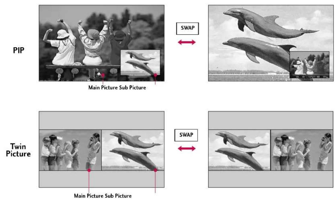
Repeatedly, use the SWAP button to switch the main and sub pictures.
■ When the main picture is Digital, Analogue or AV modes, the swapping is available.
Adjusting Main and Sub Picture Sizes for Twin Picture
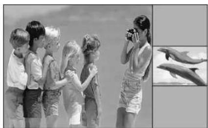
1 Use the ▲▼◀▶ button to change main and sub picture sizes in Twin Picture mode.
■ If the screen is adjusted to the maximal size, the large screen is filled with entire program vertically as shown.
natural_image
Black-and-white photo of children and a woman on a beach, with inset images showing dolphins (no text or symbols)POP (Picture-out-of-Picture : Programme Scan)
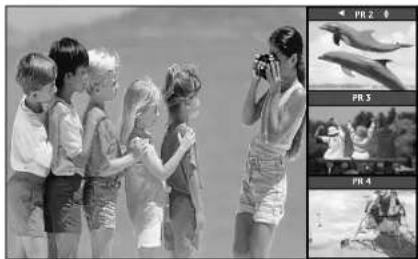
Use POP to search the programs of all the memorized programmes one-by-one on the 3 PIP screen display, (while the main picture source remains the current programme). The pictures of all the programmed programmes are searched with the 3 POP screens.
1 Press the PIP button to activate the POP mode while in PIP mode.
■ Programme selection : Use ◀ button to enlarge the selected programme being searched on the PIP screen to shift it for viewing on the Main screen.
- PIP selection : Use ▲ or ▼ button to select one of 3 PIP screen pictures in POP mode.
■ When watching Analogue TV on Main picture, Digital TV on Sub pictures are in programme scanning. However, when watching Digital TV on Main picture, only Analogue TV on Sub picture is in programme scanning.
natural_image
Black-and-white photo of children playing with a camera, alongside three inset photos showing a dolphin and water (no text or symbols)2 Press the EXIT button to cancel POP mode.
NOTE
▶ Run Auto programme before using POP mode.
SPECIAL FUNCTIONS | TELETEXT
TELETEXT
* This feature is not available in all countries.
- Teletext is a free service broadcast by most TV stations which gives up-to-the-minute information on news, weather, television programmes, share prices and many other topics.
- The teletext decoder of this TV can support the SIMPLE, TOP and FASTEXT systems. SIMPLE (standard teletext) consists of a number of pages which are selected by directly entering the corresponding page number. TOP and FASTEXT are more modern methods allowing quick and easy selection of teletext information.
Switch On/Off
Press the TEXT button to switch to teletext. The initial page or last page appears on the screen.
Two page numbers, TV station name, date and time are displayed on the screen headline. The first page number indicates your selection, while the second shows the current page displayed.
Press the TEXT or EXIT button to switch off teletext.
SIMPLE Text
* This feature is not available in all countries.
■ Page selection
Enter the desired page number as a three digit number with the NUMBER buttons. If during selection you press a wrong number, you must complete the three digit number and then re-enter the correct page number.
2 The PR +/- button can be used to select the preceding or following page.
TOP Text
* This feature is not available in all countries.
- The user guide displays four fields-red, green, yellow and blue at the bottom of the screen. The yellow field denotes the next group and the blue field indicates the next block.
■ Block / group / page selection
1 With the BLUE button you can progress from block to block.
2 Use the yellow button to proceed to the next group with automatic overflow to the next block.
3 With the GREEN button you can proceed to the next existing page with automatic overflow to the next group. Alternatively the PR + button can be used.
4 The red button permits to return to previous selection. Alternatively the PR- button can be used.
■ Direct page selection
Corresponding to the SIMPLE teletext mode, you can select a page by entering it as a three digit number using the NUMBER buttons in TOP mode.
FASTEXT
- The teletext pages are colour coded along the bottom of the screen and are selected by pressing the corresponding coloured button.
■Page selection
- Press the button to select the index page.
- You can select the pages which are colour coded along the bottom line with the same coloured buttons.
- Corresponding to the SIMPLE teletext mode, you can select a page by entering its three digit page number with the NUMBER buttons in FASTEXT mode.
- The PR +/- button can be used to select the preceding or following page.
Special Teletext Functions

REVEAL
Press this button to display concealed information, such as solutions of riddles or puzzles. Press this button again to remove the information from the display.

SIZE
Selects double height text.
Press this button to enlarge the top half of the page. Press this button again to enlarge the bottom half of the page.
Press this button again to return to the normal display.

TIME
a. When viewing a TV programme, press this button to display the time at the top right hand corner of the screen. Press this button again to remove the display.
b. In the teletext mode, press this button to select a sub page number. The sub page number is displayed at the bottom of the screen. To hold or change the sub page, press the RED, GREEN, or PR +/- buttons.
Press this function again to exit.
SPECIAL FUNCTIONS | EPG
EPG (ELECTRONIC PROGRAMME GUIDE)
- In Digital Mode Only
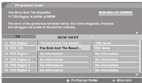
This system has an Electronic Programme Guide (EPG) to help your navigation through all the possible viewing options.
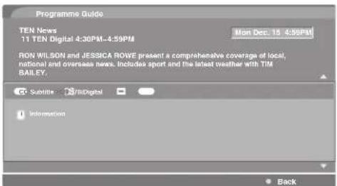
The EPG supplies information such as programme listings, start and end times for all available services. In addition, detailed information about the programme is often available in the EPG (the availability and amount of these programme details will vary, depending on the particular broadcaster).
This function can be used only when the EPG information is broadcasted by broadcasting companies.
text_image
INPUT D/A POWER TV INPUT DVD ARC VCR TEXT PIP GUIDE INFO LIST MENU VII EXIT SLEEP OKSwitch on/off EPG
Press the GUIDE button to switch on EPG.
Press the GUIDE or EXIT button again to switch off EPG and return to TV viewing.
text_image
Programme Guide The Bold And The Beautiful 11 TEN Digital 4:30PM - 4:59PM Mon Dec. 15 4:59PM The story of the glamorous ferrester family: their loves.tragedles, triumpha and struggles for power in the fashion industry. TV NOW NEXT 11 TEN Digital The Bold And The Besult... 12 TEN HD The Bold And The Besult... 13 TEN Digital 1 No Information 14 TEN Digital 2 No Information 15 TEN Digital 3 No Information 16 TEN Digital 4 No Information TEN News TEN News No Information No Information No Information No Information Pr.Change Radio More InfoSelect a programme
Press the ▲▼◀▶ button to select desired programme, then press the OK button to display the selected programme.
| Remote Control Buttons | Function |
| RED | Shows the TV or Radio programmes |
| GREEN | The detail information on or off |
text_image
Programme Guide TEN News 11 TEN Digital 4:30PM-4:59PM Mon Dec. 15 4:59PM RON WILSON and JESSICA ROWE present a comprehensive coverage of local, national and overseas news. Includes sport and the latest weather with TIM BAILEY. @ Subellite 📄Digital Information BackTV MENU
ON SCREEN MENUS SELECTION AND ADJUSTMENT
Your TV's OSD (On Screen Display) may differ slightly from what is shown in this manual. This function explains the features available on the 32/37/42LC2D*.
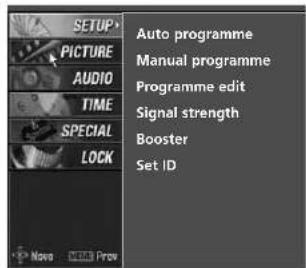
1 Press the MENU button and then use ▲ or ▼ button to select the each menu.
2 Press the ▶ button and then use ▲ ▼ ◀ ▶ button to display the available menus.
SETUP
text_image
AUTO programme MANUAL PROGRAMME PROGRAMME edit Signal strength Booster Set ID SETUP PICTURE AUDIO TIME SPECIAL LOCK Note 100 Prev

LOCK
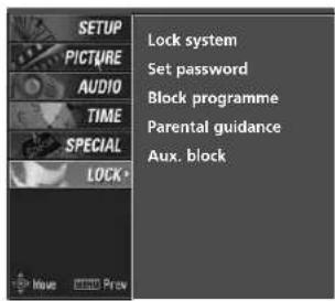
text_image
SETUP PICTURE AUDIO TIME SPECIAL LOCK* Lock system Set password Block programme Parental guidance Aux. block
SPECIAL
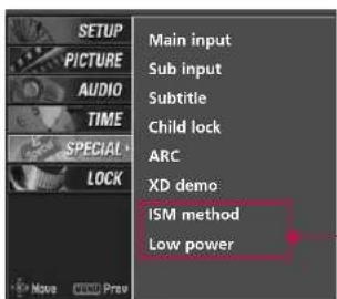
text_image
SETUP PICTURE AUDIO TIME SPECIAL LOCK Main input Sub input Subtitle Child lock ARC XD demo ISM method Low power
Only 42PC1D*, 50PC1D*, 60PC1D* models
PICTURE
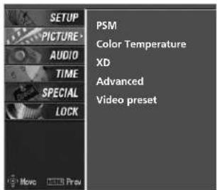
text_image
SETUP PICTURE AUDIO TIME SPECIAL LOCK PSM Color Temperature XD Advanced Video preset Move 1000 Prev
AUDIO
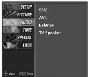
text_image
SETUP PICTURE AUDIO TIME SPECIAL LOCK SSM AVL Balance TV Speaker
TIME
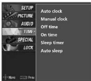
text_image
SETUP PICTURE AUDIO TIME> SPECIAL LOCK Auto clock Manual clock Off time On time Sleep timer Auto sleep
TV MENU | SETUP(Programme)
AUTO PROGRAMME TUNING
Up to 100 TV stations can be stored in this set by programme numbers (0 to 99). Once you have preset the stations, you will be able to use the PR + / - or NUMBER buttons to scan the stations you programmed. Stations can be tuned using automatic or manual modes.
A password is required to gain access to Auto programme or Manual programme menu if the Lock system is turned on.
If you forgot your password, press '7', '7', '7', '7' on the remote control.
In Australia, if no station name can be assigned to a station, the programme number is assigned and stored as ---- followed by a number see 'Assigning a station name' section to assign the station name.
text_image
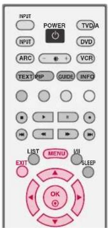
INPUT POWER TVD/A INPUT DVD ARC VCR TEXT PIP GUIDE INFO LIST MENU UII EXIT SLEEP OK1 Press the MENU button and then ▲ or ▼ button to select the SETUP menu.
2 Press the ▶ button and then ▲ or ▼ button to select Auto programme.
3 Press the ▶ button to select Storage from.
Select the beginning programme number with the ▲ △ ▼ ▽
button or NUMBER buttons.
4 Press the ▶ button to select To start.
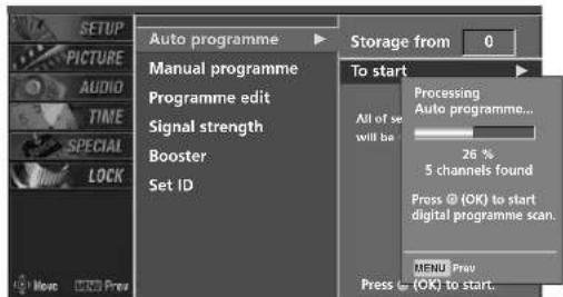
5 Press the O button to begin auto programming. All receivable stations are stored.
To stop auto programming, press the O Kutton. When auto programming is completed, the Programme edit menu appears on the screen. See the 'Programme Edit' section to edit the stored programme.
text_image
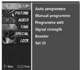
SETUP PICTURE AUDIO TIME SPECIAL LOCK Auto programme Manual programme Programme edit Signal strength Booster Set ID1

text_image
AUTO programme Manual programme Programme edit Signal strength Booster Set ID Storage from To start2 3
text_image
AUTO PROGRAMME Manual programme Programme edit Signal strength Booster Set ID Storage from 0 To start Processing Auto programme... All of set will be 26 % 5 channels found Press @ (OK) to start digital programme scan. MENU Prev (OK) to start.4 5
6 Press EXIT button to return to normal TV viewing.
MANUAL PROGRAMME TUNING
In Digital Mode
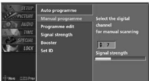
Manual programme lets you manually add a programme to your programme list.
text_image
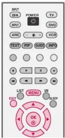
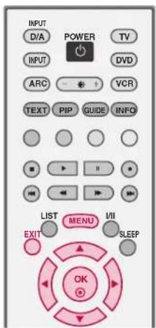
INPUT D/A POWER TV INPUT ARC - + VCR TEXT PIP GUIDE INFO LIST MENU I/II EXIT SLEEP OK1 Press the MENU button and then use ▲ or ▼ button to select the SETUP menu.
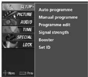
2 Press the ▶ button and then use ▲ or ▼ button to select Manual programme.
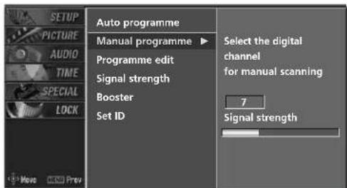
3 Press the ▶ button and then use ▲ or ▼ button to select the programme number you want to add.
4 Press the OK button to store the programme. When the programme number you want to add is already added in programme list, the message "Already programmed channel. Do you want to update?" will appear. If you want to keep on manual programming, select YES with using ▶/▶ button. Then, press the OK button. Otherwise select NNOQ When the programme is stored, the Programme edit menu appears on the screen. See the 'Programme Edit' section to edit the stored programme.
5 Press EXIT button to return to normal TV viewing.
text_image
AUTO PROGRAMME MANUAL PROGRAMME PROGRAMME edit Signal strength Booster Set ID1
text_image
AUTO PROGRAMME Manual programme ▶ Programme edit Signal strength Booster Set ID Select the digital channel for manual scanning 7 Signal strength2
text_image
AUTO PROGRAMME Manual programme Programme edit Signal strength Booster Set ID Select the digital channel for manual scanning 7 Signal strength3 4
TV MENU | SETUP(Programme)
MANUAL PROGRAMME TUNING Continued
In Analogue Mode
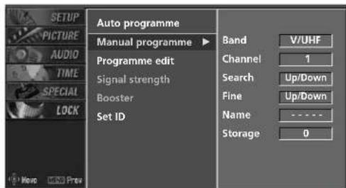
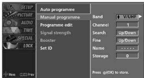
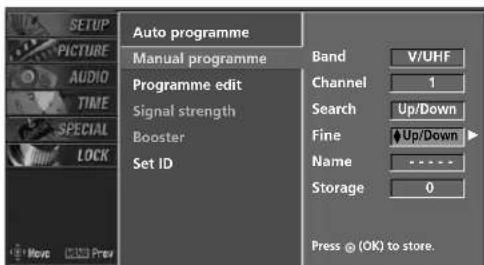
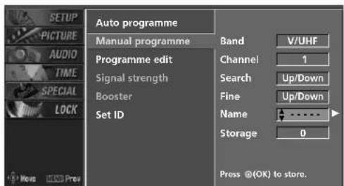
Manual programme lets you manually tune and arrange the stations in whatever order you desire. Also you can assign a station name with five characters to each programme number.
1 Press the MENU button and then use ▲ or ▼ button to select the SETUP menu.
2 Press the ▶ button and then use ▲ or ▼ button to select Manual programme.
3 Press the ▶ button to select Band. Press the ▲ or ▼ button to select V/UHF or Cable as required.
4 Press the ▶ button to select Channel. Press the ▲ or ▼ button to select the desired channel number.
5 Press the ▶ button to select Search. Press the ▲ or ▼ button to commence searching. If a station is found the search will stop.
6 If this station is the one required, press the ◀ or ▶ button to select Storage. Select the desired programme number with the ▲ or ▼ button.
7 Press the OK button to store it.
8 To store another station, repeat steps 3 to 7.
9 Press EXIT button to return to normal TV viewing.
text_image
INPUT D/A POWER TV INPUT DVD ARC VCR TEXT PIP GUIDE INFO LIST MENU VII EXIT SLEEP OK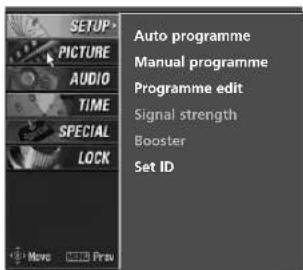
text_image
AUTO programme MANUAL PROGRAMME PROGRAMME edit Signal strength Booster Set ID1
text_image
AUTO PROGRAMME Manual programme ▶ Programme edit Signal strength Booster Set ID Band V/UHF Channel 1 Search Up/Down Fine Up/Down Name - Storage 02
text_image
AUTO PROGRAMME Manual programme Programme edit Signal strength Booster Set ID Band V/UHF Channel 1 Search Up/Down Fine Up/Down Name - Storage 0 Press @(OK) to store.3 4 5 6 7
FINE TUNING - In Analogue Mode only
Normally fine tuning is only necessary if reception is poor. The finely tuned programme will be indicated by a yellow number during programme selection.
text_image
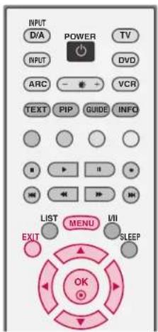
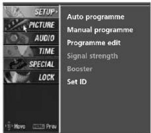
INPUT D/A POWER TV INPUT ARC - + VCR TEXT PIP GUIDE INFO LIST MENU MII EXIT SLEEP OK1 Press the MENU button and then use ▲ or ▼ button to select the SETUP menu.
2 Press the ▶ button and then use ▲ or ▼ button select Manual programme.
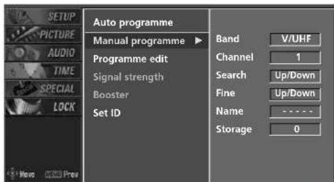
3 Press the ▶ button and then ◀ or ▶ button to select Fine.
4 Press the ▲ or ▼ button to fine tune for the best picture and sound.
5 Press the O O Button to store.
6 Press EXIT button to return to normal TV viewing.
text_image
AUTO programme MANUAL PROGRAMME PROGRAMME edit Signal strength Booster Set ID1
text_image
AUTO PROGRAMME Manual programme ▶ Programme edit Signal strength Booster Set ID Band V/UHF Channel 1 Search Up/Down Fine Up/Down Name ---- Storage 02
text_image
AUTO PROGRAMME Manual programme Programme edit Signal strength Booster Set ID Band V/UHF Channel 1 Search Up/Down Fine Up/Down Name - Storage 0 Press © (OK) to store.3 4 5
TV MENU | SETUP(Programme)
ASSIGNING A STATION NAME - In Analogue Mode only
You can assign a station name with the characters to each programme number.
text_image
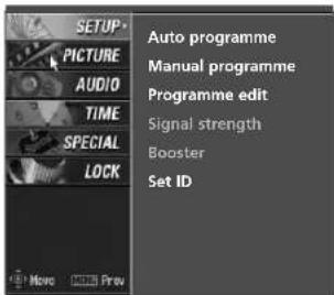
INPUT D/A POWER TV INPUT ARC - + VCR TEXT PIP GUIDE INFO LIST MENU I/II EXIT SLEEP OK1 Press the MENU button and then use ▲ or ▼ button to select the SETUP menu.
2 Press the ▶ button and then use ▲ or ▼ button to select Manual programme.
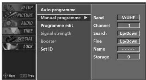
3 Press the ▶ button and then use ◀ or ▶ button to select Name.
4 Press the ▲ or ▼ button. You can use the numeric 0 to 9, the alphabet A to Z +, -, and blank.
5 Press the ◀ or ▶ button to select the position and make your choice of the second character, and so on.
6 Press the OK button to store.
7 Press EXIT button to return to normal TV viewing.
text_image
AUTO programme MANUAL PROGRAMME PROGRAMME edit Signal strength Booster Set ID1
text_image
AUTO PROGRAMME Manual programme ▶ Programme edit Signal strength Booster Set ID Band V/UHF Channel 1 Search Up/Down Fine Up/Down Name ------------------ Storage 02
text_image
AUTO PROGRAMME Manual programme Programme edit Signal strength Booster Set ID Band V/UHF Channel 1 Search Up/Down Fine Up/Down Name ------------------ Storage 0 Press @(OK) to store.3 4 5
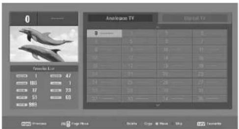
PROGRAMME EDIT
This function enables you to delete or skip the stored programmes. Also you can move some stations to other programme numbers or copy blank station data into the selected programme number.
text_image
INPUT D/A POWER TV INPUT DVD ARC VCR TEXT PIP GUIDE INFO LIST MENU MII EXIT SLEEP OK1 Press the MENU button and then use ▲ or ▼ button to select the SETUP menu.
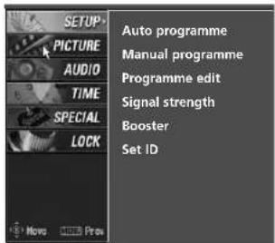
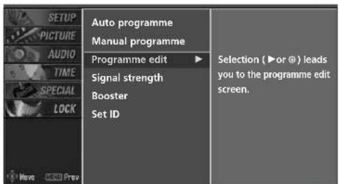
2 Press the ▶ button and then use ▲ or ▼ button to select Programme edit.
3 Press the ▶ button.
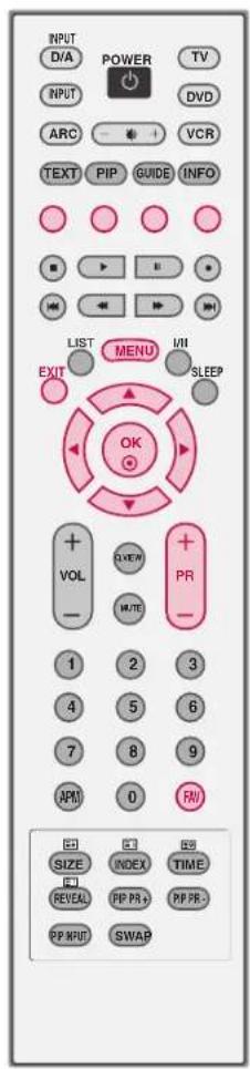
4 ■ Deleting a programme (In Analogue Mode Only)
a. Select a programme to be deleted with the ▲▼▼ button.
b. Press the RED button twice. The selected programme is deleted, all the following programmes are shifted up one position.
■ Copying a programme (In Analogue Mode Only)
a. Select a programme to be copied with the ▲▼◀ button.
b. Press the GREEN button.
c. Move the programme to the desired programme number with the ▲▼◀▶ button.
d. Press the GREEN button again to copy the programme. All the following programmes are shifted down one position.
text_image
AUTO programme MANUAL PROGRAMME PROGRAMME edit Signal strength Booster Set ID1
text_image
AUTO MANUAL PROGRAMME PROGRAMME edit ▶ Signal strength Booster Set ID Selection (▶or @) leads you to the programme edit screen.2
text_image
0 Analog TV Original TV Favorite List 1 47 100 1 17 78 51 60 983 0 1 5 2 7 2 3 10 11 3 12 14 16 4 12 16 18 5 91 94 97 6 25 28 29 7 34 36 38 8 42 44 46 9 98 99 10 11 12 13 14 15 16 17 18 19 20 21 22 23 24 25 26 27 28 29 30 31 32 33 34 35 36 37 38 39 40 41 42 43 44 45 46 47 48 49 50 51 52 53 54 55 56 57 58 59 60 61 62 63 64 65 66 67 68 69 70 71 72 73 74 75 76 77 78 79 803 4 5
TV MENU | SETUP(Programme)
■ Moving a programme (In Analogue Mode Only)
a. Select a programme to be moved with ▲ ▼ ◀ ▶ button.
b. Press the YELLOW button.
c. Move the programme to the desired programme number with the ▲▼◀▶ button.
d. Press the YELLOW button again to release this function.
■ Skipping a programme number
a. Select a programme number to be skipped with ▲▼◀▶ button.
b. Press the BLUE button. The skipped programme number turns to blue.
c. Press the BLUE button again to release the skipped programme.
When a programme number is skipped it means that you will be unable to select it using the PR+ / -button during normal TV viewing. If you want to select the skipped programme, directly enter the programme number with the NUMBER buttons or select it in the programme edit or table menu.
■ Selecting Favourite Programme
a. Select your favourite programme number with ▲▲▼ ◀▶ button and then press the FAV button. It will automatically include the selected programme into your favourite programmes list and a heartmark will appear in front of that programme number. You can store up to 10 programmes.
5 Repeatedly press the FAV button to select stored favourite programmes in normal TV viewing.
text_image
INPUT D/A POWER TV INPUT ARC VCR TEXT PIP GUIDE INFO LIST MENU I/II EXIT SLEEP OK VOL + - OU/EN + - PR 1 2 3 4 5 6 7 8 9 APM 0 R/ SIZE INDEX TIME REVEAL PP PR+ PP PR- PP INPUT SWAPCALLING UP THE PROGRAMME TABLE
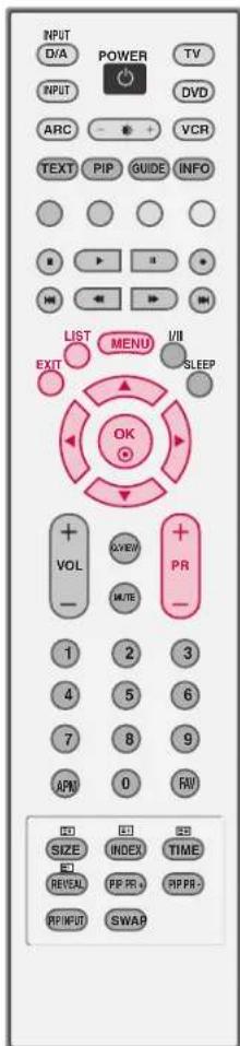
You can check the programmes stored in the memory by displaying the programme list.
Displaying programme list
■ Press the LIST button to display the Programme table menu.
The programme table appears on the screen.
NOTE
▶ You may find some blue programmes.
They have been set up to be skipped by auto programming or in the programme edit mode.
Some programmes with the channel number shown in the programme LIST indicate there is no station name assigned.
Selecting a programme in the programme table
1 Select a programme with the ▲ ▼ ◀ ▶ button.
2 The set switches to the chosen programme number.
Paging through a programme table
1 Press the PR+ / -- button to changes current page into previous/next page.
2 Press the LIST button to return to normal TV viewing.
text_image
INPUT D/A POWER TV INPUT ARC VCR TEXT PIP GUIDE INFO LIST MENU I/II EXIT OK SLEEP VOL ΔVIEW PR - MUTE 1 2 3 4 5 6 7 8 9 APN 0 RV SIZE INDEX TIME REVEAL PP PR PP PR- PP INPUT SWAPTV MENU | SETUP(Programme)
DIGITAL SIGNAL STRENGTH - In Digital Mode only
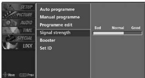
Reveals how strong your DTV signal is and whether you need to adjust your antenna.
The higher the signal strength, the less likely you are to experience picture degradation.
Digital TV Signals; May not be available in all areas, nor broadcast all programmes.
text_image
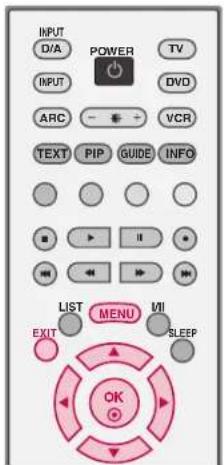
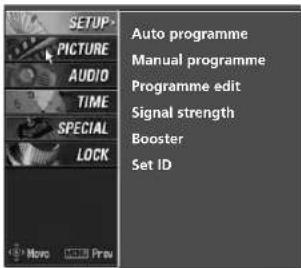
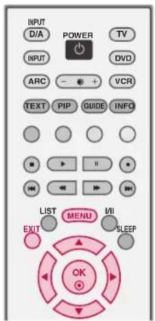
INPUT D/A POWER TV INPUT ARC VCR TEXT PIP GUIDE INFO LIST MENU MII EXIT SLEEP OK1 Press the MENU button and then use ▲ or ▼ button to select the SETUP menu.
2 Press the ▶ button and then use ▲ or ▼ button to select Signal strength.
3 View the on-screen signal strength monitor to see the strength of the signal being received.
text_image
SETUP PICTURE AUDIO TIME SPECIAL LOCK Auto programme Manual programme Programme edit Signal strength Booster Set ID Move Apply1
text_image
AUTO PROGRAMME MANUAL PROGRAMME PROGRAMME edit Signal strength Booster Set ID Bad Normal Good2
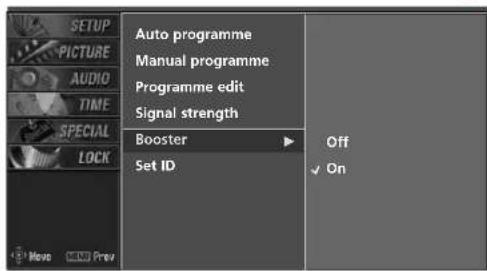
BOOSTER - In Digital Mode only
If the reception is poor at the fringed area of TV signal, select Boosterto OOnWhen the picture condition is good, do not select Booster to OOn
text_image
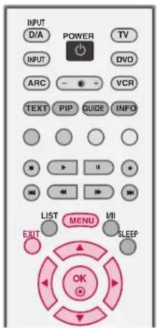
INPUT D/A POWER TV INPUT ARC - + VCR TEXT PIP GUIDE INFO LIST MENU EXIT SLEEP OK1 Press the MENU button and then use ▲ or ▼ button to select the SETUP menu.
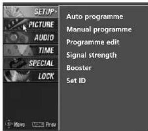
2 Press the ▶ button and then use ▲ or ▼ button to select Booster.
3 Press the ▶ button and then use ▲ or ▼ button to select Off or O○.nn
4 Press EXIT button to return to normal TV viewing.
text_image
AUTO programme MANUAL PROGRAMME PROGRAMME edit Signal strength Booster Set ID1
text_image
AUTO PROGRAMME MANUAL PROGRAMME PROGRAMME edit Signal strength Booster Set ID Off On2 3
TV MENU | PICTURE ADJUSTMENT
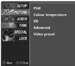
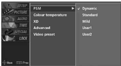
PICTURE STATUS MEMORY (PSM)
This function adjusts the set to the best picture appearance. When adjusting picture options (contrast, brightness, colour, sharpness and tint) manually, PSM is automatically changed to User.
Picture options Dynamic, Standard, and Mild are preset and programmed for good picture quality at the factory and cannot be changed.
text_image
INPUT D/A POWER TV INPUT DVD ARC VCR TEXT PIP GUIDE INFO LIST MENU VII EXIT SLEEP OK1 Press the MENU button and then use ▲ or ▼ button to select the PICTURE menu.
2 Press the ▶ button and then use ▲ or ▼ button to select PSM.
3 Press the ▶ button and then use ▲ or ▼ button to select Dynamic, Standard, Mild, User1, or User2.
4 Press EXIT button to return to normal TV viewing.
text_image
SETUP PICTURE AUDIO TIME SPECIAL LOCK PSM Colour temperature XD Advanced Video preset Know Preview1
text_image
SETUP PICTURE AUDIO TIME SPECIAL LOCK PSM Colour temperature XD Advanced Video preset Dynamic Standard Mild User1 User22 3
ADAPTIVE PICTURE MODE (APM)
Allows you to select your preferred picture mode after compairing the four different picture (Dynamic, Standard, Mild, and User1 (or User2)) settings.
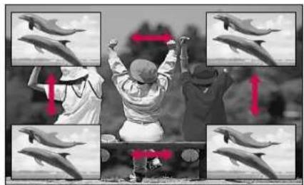
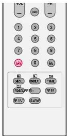
1 Press the APM button at once. The screen is divided to 4-split.
Use the ▲▼◀▶ button to navigate 4 screen. By pressing the ○ button, you can select the desired mode.
NOTE
While operating the 4-split, any button except POWER, APM, O, EXIT, ▲ ▼ ▶ ▶, VOLUME ▲ △ ▼MUTE button on the remote control are not usable.
▶ APM screen will automatically disappear after approx. 40 seconds unless a button is pressed.
BRIGHTNESS ADJUSTMENT
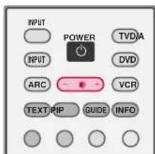
Adjust the brightness with using this button on the remote control.
1 Press the button.
2 Adjust the desired screen brightness.
text_image
VOL — MINS — 1 2 3 4 5 6 7 8 9 APM 0 RW E1 E2 E3 SIZE INDEX TIME E4 RESEALPP PR+ PP PR- PPRRT SWAP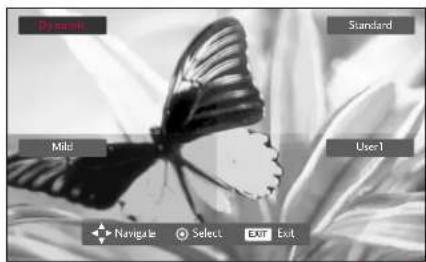
text_image
Dy smile Standard Mild User-1 Navigate Select Exit Exit1 2
text_image
INPUT POWER TVDIA INPUT DVD ARC VCR TEXT/PIP GUIDE INFO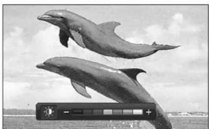
natural_image
Two dolphins leaping out of water with a camera display showing solar panel (no text or symbols on the dolphins or background)1 2
TV MENU | PICTURE ADJUSTMENT
MANUAL PICTURE CONTROL (PSM-User option)
You can adjust picture Contrast, Brightness, Colour, Sharpness, and Tint options to the levels you prefer. In NTSC AV, Component 60Hz, RGB-DTV 60Hz, HDMI/DVI-DTV 60Hz, RGB-PC, HDMI/DVI-PC mode, Tint is available.
The adjustment for PICTURE menu (Contrast, Brightness, Colour, Sharpness, and Tint) affect both the main and sub picture in PIP or Twin Picture mode.
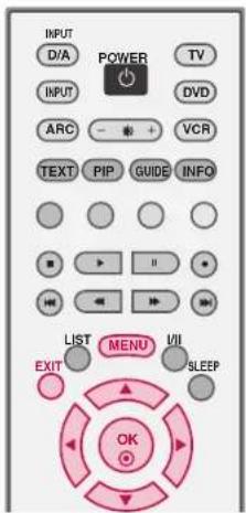
1 Press the MENU button and then use ▲ or ▼ button to select the PICTURE menu.
2 Press the ▶ button and then use ▲ or ▼ button to select PSM.
3 Press the ▶ button and then use ▲ or ▼ button to select User 1 or User 2.
4 Press the ▶ button and then use ▲ or ▼ button to select the desired picture option (Contrast, Brightness, Colour, Sharpness, or Tin).
5 Press the ▶ button and then use ◀ or ▶ button to make appropriate adjustments.
6 Press EXIT button to return to normal TV viewing.
text_image
INPUT D/A POWER TV INPUT ARC - + VCR TEXT PIP GUIDE INFO LIST MENU VII EXIT SLEEP OK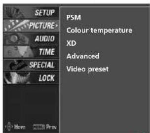
text_image
SETUP PICTURE AUDIO TIME SPECIAL LOCK PSM Colour temperature XD Advanced Video preset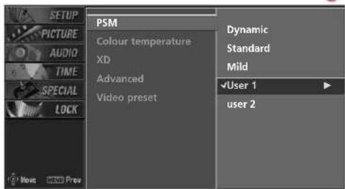
text_image
SETUP PICTURE AUDIO TIME SPECIAL LOCK PSM Colour temperature XD Advanced Video preset Dynamic Standard Mild ✓User 1 user 22 3
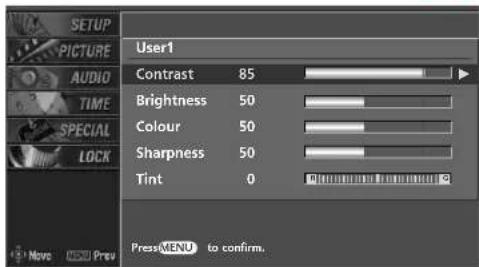
text_image
SETUP PICTURE AUDIO TIME SPECIAL LOCK User1 Contrast 85 Brightness 50 Colour 50 Sharpness 50 Tint 0 PressMENU to confirm.4
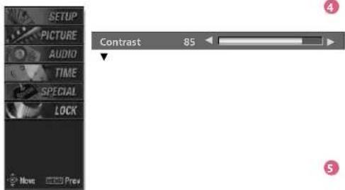
text_image
SETUP PICTURE AUDIO TIME SPECIAL LOCK Contrast 85 Now: ProvXD
XD is LG Electronic's unique picture improving technology to display a real HD source through an advanced digital signal processing algorithm.
When selecting PSM options (Dynamic, Standard and Mild), XD is automatically change to Auto.
But when selecting PSM options (User 1 and User 2), you can choose the Auto / Manual.
When selecting the Manual, you can adjust the XD contrast, XD colour and XD noise.
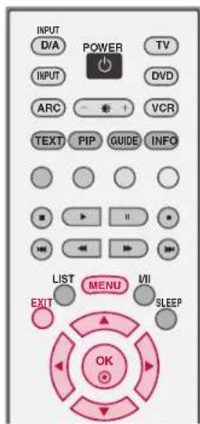
text_image
INPUT D/A POWER TV INPUT ARC VCR TEXT PIP GUIDE INFO LIST MENU VII EXIT SLEEP OK1 Press the MENU button and then use ▲ or ▼ button to select the PICTURE menu.
2 Press the ▶ button and then use ▲ or ▼ button to select XXDD
3 Press the ▶ button and then use ▲ or ▼ button to select Auto or Manual.
Selecting the Manual
-
Press the ▶ button and then use ◀ or ▶ button to select XD contrast, XD colour or XD noise.
-
XD contrast: Optimizing the contrast automatically according to the brightness of the reflection.
- XD colour: Adjusting the colors of the reflection automatically to reproduce as closely as possible to the natural colors.
- XD noise : Removing the noise up to the point where it does not damage the original picture.
- Use the ▲ or ▼ button to select O○ on Off.
4 Press EXIT button to return to normal TV viewing.
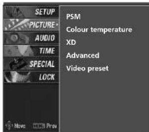
text_image
SETUP PICTURE AUDIO TIME SPECIAL LOCK PSM Colour temperature XD Advanced Video preset Move Preview1
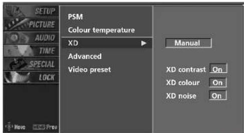
text_image
PSTM Colour temperature XD Advanced Video preset Manual XD contrast On XD colour On XD noise On2 3
TV MENU | PICTURE ADJUSTMENT
COLOUR TEMPERATURE CONTROL
Auto Colour Temperature Control
Choose one of three automatic color adjustments. Set to warm to enhance hotter colors such as red, or set to cool to see less intense colors with more blue.
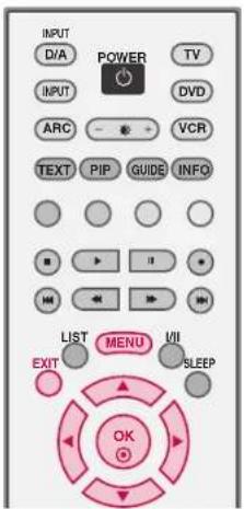
text_image
INPUT D/A POWER TV INPUT DVD ARC VCR TEXT PIP GUIDE INFO LIST MENU VII EXIT SLEEP OK1 Press the MENU button and then use ▲ or ▼ button to select the PICTURE menu.
2 Press the ▶ button and then use ▲ or ▼ button to select Colour temperature.
3 Press the ▶ button and then use ▲ or ▼ button to select either Warm, Medium, Cool, or User.
4 Press EXIT button to return to normal TV viewing.
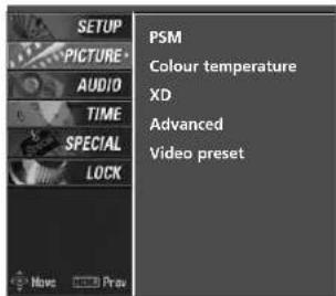
text_image
SETUP PICTURE AUDIO TIME SPECIAL LOCK PSM Colour temperature XD Advanced Video preset Move Print1
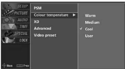
text_image
SETUP PICTURE AUDIO TIME SPECIAL LOCK Move DOWN Prev PSM Colour temperature ▶ XD Advanced Video preset Warm Medium ✓ Cool User2 3
Manual Colour Temperature Control
You can also adjust the detailed settings (Red, Green, Blue) by selecting the User menu.
1 Press the MENU button and then use ▲ or ▼ button to select the PICTURE menu.
2 Press the ▶ button and then use ▲ or ▼ button to select Colour temperature.
3 Press the ▶ button and then use ▲ or ▼ button to select User.
4 Press the ▶ button and then use ▲ or ▼ button to select Red, Green, or Blue.
5 Press the ▶ button and then use ◀ or ▶ button to make appropriate adjustments.
■ The adjustment range of Red, Green, or Blue is -20\~+20.
6 Press EXIT button to return to normal TV viewing.
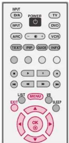
text_image
INPUT D/A POWER TV INPUT DVD ARC - + VCR TEXT PIP GUIDE INFO LIST MENU UII EXIT SLEEP OK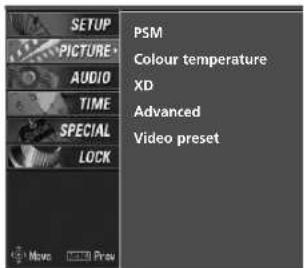
text_image
SETUP PICTURE AUDIO TIME SPECIAL LOCK PSM Colour temperature XD Advanced Video preset Move Preview1
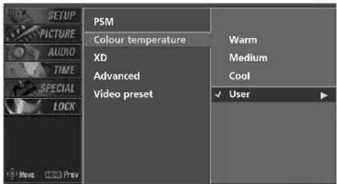
text_image
SETUP PICTURE AUDIO TIME SPECIAL LOCK PSM Colour temperature XD Advanced Video preset Warm Medium Cool ✓ User2 3
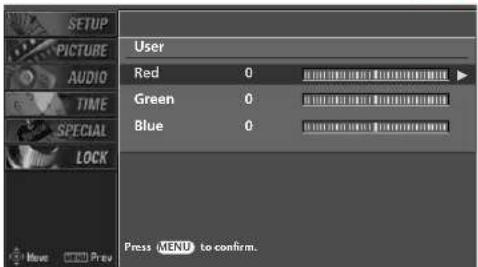
text_image
SETUP PICTURE AUDIO TIME SPECIAL LOCK User Red 0 Green 0 Blue 0 Press MENU to confirm.4
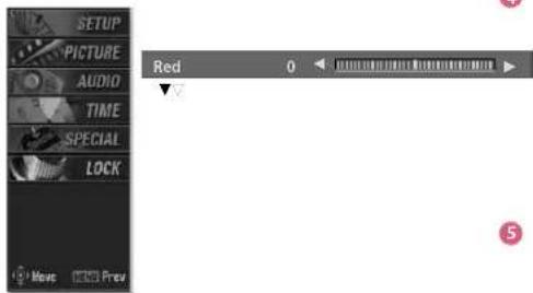
text_image
SETUP PICTURE AUDIO TIME SPECIAL LOCK Red 0 5TV MENU | PICTURE ADJUSTMENT
ADVANCED-CINEMA
Set up the TV for the best picture appearance for viewing movies.
This feature operates only in AV1, AV2, and Component480i mode.
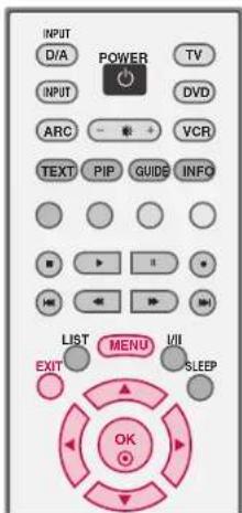
text_image
INPUT D/A POWER TV INPUT DVD ARC VCR TEXT PIP GUIDB INFO LIST MENU I/II EXIT SLEEP OK1 Press the MENU button and then use ▲ or ▼ button to select the PICTURE menu.
2 Press the ▶ button and then use ▲ or ▼ button to select Advanced.
3 Press the ▶ button and then use ▲ or ▼ button to select Cinema.
4 Press the ▶ button and then use ▲ or ▼ button to select O○orOff
5 Press EXIT button to return to normal TV viewing.
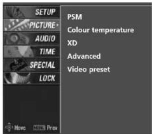
text_image
SETUP PICTURE AUDIO TIME SPECIAL LOCK PSM Colour temperature XD Advanced Video preset Move Preview1
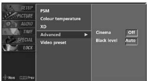
text_image
PSM Colour temperature XD Advanced Video preset Cinema Off Black level Auto2 3 4
Adjusting the contrast and the brightness of the screen using the black level of the screen.
This feature operates only in AV1, AV2, or HDMI/DVI mode.
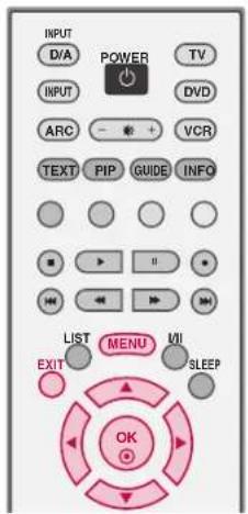
text_image
INPUT D/A POWER TV INPUT DVD ARC - * + VCR TEXT PIP GUIDE INFO LIST MENU VII EXIT SLEEP OK1 Press the MENU button and then use ▲ or ▼ button to select the PICTURE menu.
2 Press the ▶ button and then use ▲ or ▼ button to select Advanced.
3 Press the ▶ button and then use ▲ or ▼ button to select Black Level
4 Press the ▶ button and then use ▲ or ▼ button to select Auto, Low, or High
Auto
Realizing the black level of the screen and set it to High or Low automatically.
Low
The reflection of the screen gets darker.
High
The reflection of the screen gets brighter.
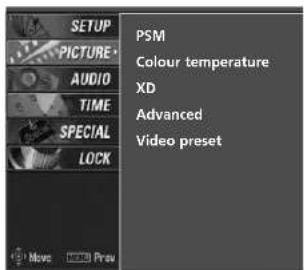
text_image
SETUP PICTURE AUDIO TIME SPECIAL LOCK PSM Colour temperature XD Advanced Video preset Move Preu1
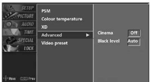
text_image
SETUP PICTURE AUDIO TIME SPECIAL LOCK PSM Colour temperature XD Advanced Video preset Cinema Off Black level Auto2 3 4
5 Press EXIT button to return to normal TV viewing.
TV MENU | PICTURE ADJUSTMENT
VIDEO PRESET
Use to quickly reset all the Picture menu options to their original factory preset values.
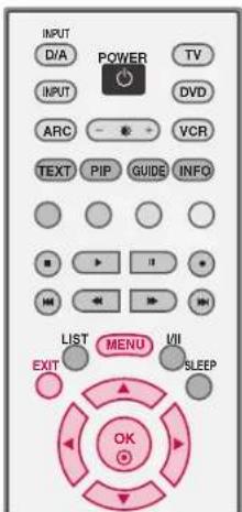
text_image
INPUT D/A POWER TV INPUT DVD ARC VCR TEXT PIP GUIDE INFO LIST MENU VII EXIT SLEEP OK1 Press the MENU button and then use ▲ or ▼ button to select the PICTURE menu.
2 Press the ▶ button and then use ▲ or ▼ button to select Video preset
3 Press the ▶ button to reset the picture menu options to original values.
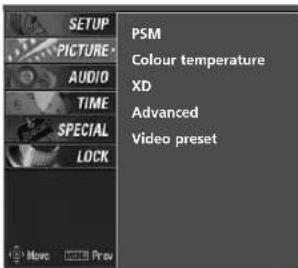
text_image
SETUP PICTURE AUDIO TIME SPECIAL LOCK PSM Colour temperature XD Advanced Video preset1
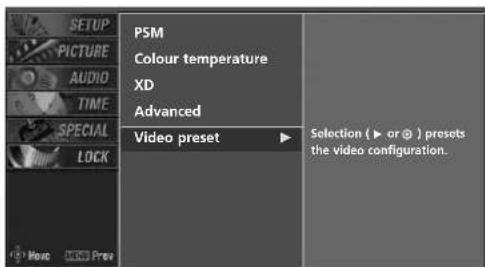
text_image
P5M Colour temperature XD Advanced Video preset Selection (► or ⊕ ) presets the video configuration.2 3
TV MENU | AUDIO ADJUSTMENT
SOUND STATUS MEMORY (SSM)
SSM lets you enjoy the best sound without any special adjustment because the TV sets the appropriate sound options based on the programme content.
When adjusting sound options (treble and bass) manually, SSM is automatically changed to User.
Standard, Music, Movie, and Sports are preset for good sound quality at the factory and are not adjustable.
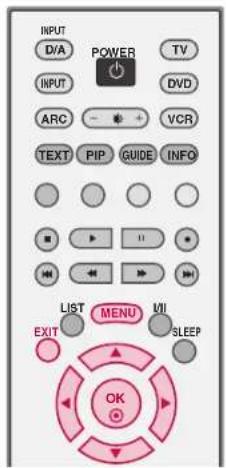
text_image
INPUT D/A POWER TV INPUT DVD ARC VCR TEXT PIP GUIDE INFO LIST MENU UI EXIT SLEEP OK1 Press the MENU button and then use ▲ or ▼ button to select the AUDIO menu.
2 Press the ▶ button and then use ▲ or ▼ button to select SSM.
3 Press the ▶ button and then use ▲ or ▼ button to select Standard, Music, Movie, Sports, or User.
4 Press EXIT button to return to normal TV viewing.
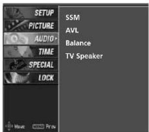
text_image
SETUP PICTURE AUDIO TIME SPECIAL LOCK SSM AVL Balance TV Speaker1
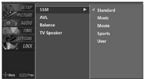
text_image
SETUP PICTURE AUDIO TIME SPECIAL LOCK SSM AVL Balance TV Speaker Standard Music Movie Sports User2 3
TV MENU | AUDIO ADJUSTMENT
MANUAL SOUND CONTROL (SSM-User option)
Adjust the sound to suit your taste and room situations.
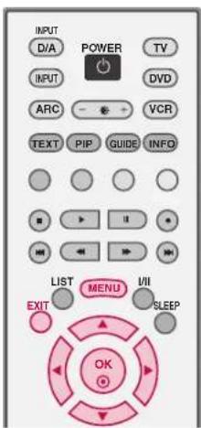
text_image
INPUT D/A POWER TV INPUT ARC VCR TEXT PIP GUIDE INFO LIST MENU VII EXIT SLEEP OK1 Press the MENU button and then use ▲ or ▼ button to select the AUDIO menu.
2 Press the ▶ button and then use ▲ or ▼ button to select SSM.
3 Press the ▶ button and then use ▲ or ▼ button to select User.
4 Press the ▶ button and then use ▲ or ▼ button to select the desired sound option (Treble, Bass, or Front surround).
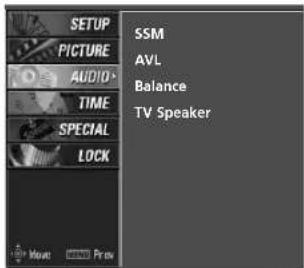
text_image
SETUP PICTURE AUDIO TIME SPECIAL LOCK SSM AVL Balance TV Speaker1
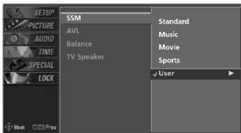
text_image
SETUP PICTURE AUDIO TIME SPECIAL LOCK SSM AVL Balance TV Speaker Standard Music Movie Sports User2 3
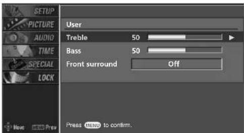
text_image
SETUP PICTURE AUDIO TIME SPECIAL LOCK User Treble 50 Bass 50 Front surround Off Press MENU to confirm.4
5 Press the ▶ button and then use ◀ or ▶ button to make appropriate adjustments.
Selecting the Front surround
Press the ▶ button and then use ◀ or ▶ button to select Offor SRS(Sound Retrieval System)TruSurround XT.
Front surround SRS TruSurround XT
6 Press EXIT button to return to normal TV viewing.
SRS TruSurround XT
Takes advantage of any multi-channel format without needing to add extra speakers or equipment. Dialog clarity, bass enrichment, and the addition of stereo audio enhancement produces an immersive sound experience from standard stereo material.
TV MENU | AUDIO ADJUSTMENT
AUTO VOLUME LEVELER (AVL)
AVL automatically keeps on an equal volume level even if you change programmes.
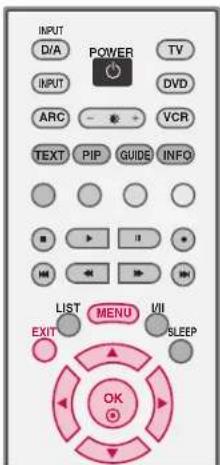
text_image
INPUT D/A POWER TV INPUT DVD ARC VCR TEXT PIP GUIDE INFO LIST MENU VII EXIT SLEEP OK1 Press the MENU button and then use ▲ or ▼ button to select the AUDIO menu.
2 Press the ▶ button and then use ▲ or ▼ button to select AVL.
3 Press the ▶ button and then use ▲ or ▼ button to select Off or OQnn
4 Press EXIT button to return to normal TV viewing.
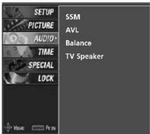
text_image
SETUP PICTURE AUDIO TIME SPECIAL LOCK SSM AVL Balance TV Speaker1
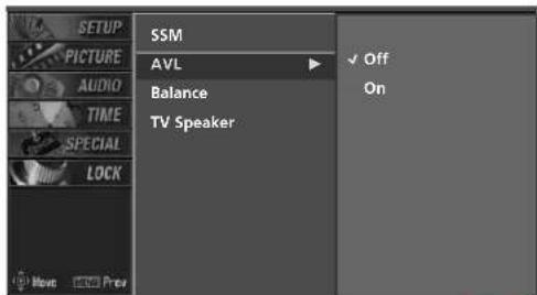
text_image
SETUP PICTURE AUDIO TIME SPECIAL LOCK SSM AVL Balance TV Speaker Off On2 3
BALANCE
Adjust the left/right sound of speaker to suit your taste and room situations.
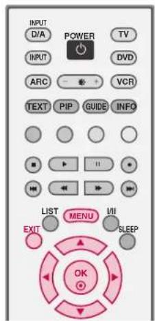
text_image
INPUT D/A POWER TV INPUT ARC VCR TEXT PIP GUIDE INFO LIST MENU VII EXIT SLEEP OK1 Press the MENU button and then use ▲ or ▼ button to select the AUDIO menu.
2 Press the ▶ button and then use ▲ or ▼ button to select Balance.
3 Press the ▶ button and then use ◀ or ▶ button to make appropriate adjustments.
4 Press EXIT button to return to normal TV viewing.
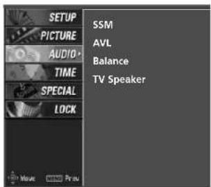
text_image
SETUP PICTURE AUDIO TIME SPECIAL LOCK SSM AVL Balance TV Speaker1
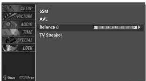
text_image
SETUP PICTURE AUDIO TIME SPECIAL LOCK SSM AVL Balance 0 TV Speaker2
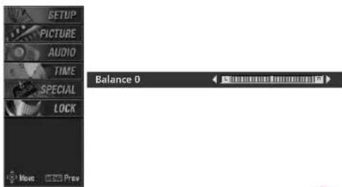
text_image
SETUP PICTURE AUDIO TIME SPECIAL LOCK Balance 0 More Less Prev3
TV MENU | AUDIO ADJUSTMENT
TV SPEAKERS ON/OFF SETUP
Turn the TV speakers off if using external audio equipment. In AV1-2, Component1-2, RGB PC/DTV and HDMI/DVI mode, the audio signal can be outputted even though there is no video signal.
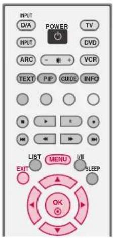
text_image
INPUT D/A POWER TV INPUT DVD ARC VCR TEXT PIP GUIDE INFO LIST MENU VII EXIT SLEEP OK1 Press the MENU button and then use ▲ or ▼ button to select the AUDIO menu.
2 Press the ▶ button and then use ▲ or ▼ button to select TV Speaker.
3 Press the ▶ button and then use ▲ or ▼ button to select Off or O○nn
4 Press EXIT button to return to normal TV viewing.
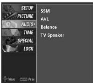
text_image
SETUP PICTURE AUDIO> TIME SPECIAL LOCK SSM AVL Balance TV Speaker1
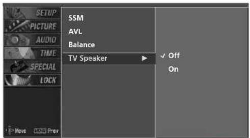
text_image
SETUP PICTURE AUDIO TIME SPECIAL LOCK SSM AVL Balance TV Speaker Off On2 3
STEREO RECEPTION - In Analogue Mode only
■ Mono sound selection
If the stereo signal is weak in stereo reception, you can switch to mono by pressing the I/II button twice. In mono reception, the depth of sound is improved. To switch back to stereo, press the I/II button twice again.
Broadcast On Screen Display
Mono MONO
Stereo MONO / STEREO
SOUND OUTPUT SELECTION
In AV 1-2, Component 1-2, RGB-PC/DTV or HDMI/DVI mode, you can select output sound for the left and right loudspeakers.
Repeatedly press the I/II button to select the sound output.
L+R: Audio signal from audio L input is sent to the left loud speaker and audio signal from audio R input is sent to the right loud speaker.
L+L: Audio signal from audio L input is sent to left and right loud speakers.
R+R: Audio signal from audio R input is sent to left and right loud speakers.
NOTE
In digital mode, repeatedly press the I/II button to change the audio mode (MPEG or DOLBY DIGITAL).
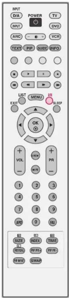
text_image
INPUT D/A POWER TV INPUT DVD ARC - + VCR TEXT PIP GUIDE INFO LIST MENU I/II EXIT SLEEP OK + VIEW + VOL M/TE PR - 1 2 3 4 5 6 7 8 9 APM 0 FW SIZE INDEX TIME REVEAL PP PR PP PR- PP INPUT SWAPTV MENU | TIME SETTING
AUTO CLOCK SETUP
The time is automatically set from a digital channel signal.
The digital channel signal includes information for the current time provided by the broadcasting station.
Set the clock manually, if the current time is set incorrectly by the auto clock function.
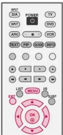
text_image
INPUT D/A POWER TV INPUT ARC VCR TEXT PIP GUIDE INFO LIST MENU VII EXIT SLEEP OK1 Press the MENU button and then use ▲ or ▼ button to select the TIME menu.
2 Press the ▶ button and then use ▲ or ▼ button to select Auto clock.
3 Press the ▶ button and then use ▲ or ▼ button to select OQnn
4 Press the ▶ button and then use ▲ or ▼ button to select your viewing area time zone:
NSW/ACT, NNTAS, WA,S.AQLD, or VIC
5 Press EXIT button to return to normal TV viewing.
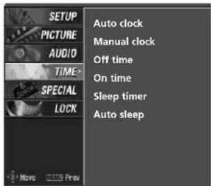
text_image
SETUP PICTURE AUDIO TIME SPECIAL LOCK Auto clock Manual clock Off time On time Sleep timer Auto sleep1
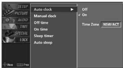
text_image
AUTO clock Manual clock Off time On time Sleep timer Auto sleep Off On Time Zone NSW/ACT2
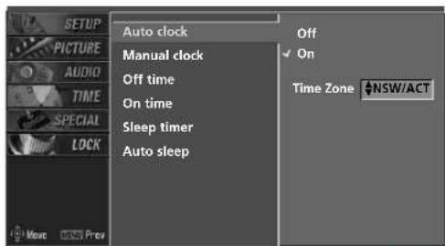
text_image
AUTO clock Manual clock Off time On time Sleep timer Auto sleep Off On Time Zone #NSW/ACT3 4
MANUAL CLOCK SETUP
If the current time setting is wrong, reset the clock manually.
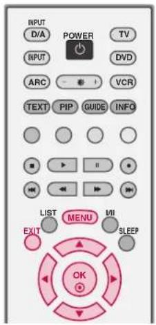
text_image
INPUT D/A POWER TV INPUT ARC VCR TEXT PIP GUIDE INFO LIST MENU EXIT SLEEP OK1 Press the MENU button and then use ▲ or ▼ button to select the TIME menu.
2 Press the ▶ button and then use ▲ or ▼ button to select Manual clock.
3 Press the ▶ button and then use ◀ or ▶ to select either the year, date, or time option. Once selected, use the ▲ or ▼ button to set the year, date, and time options.
4 Press EXIT button to return to normal TV viewing.
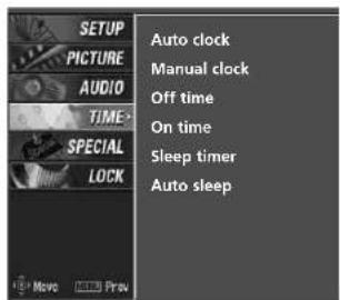
text_image
SETUP PICTURE AUDIO TIME- SPECIAL LOCK Auto clock Manual clock Off time On time Sleep timer Auto sleep1
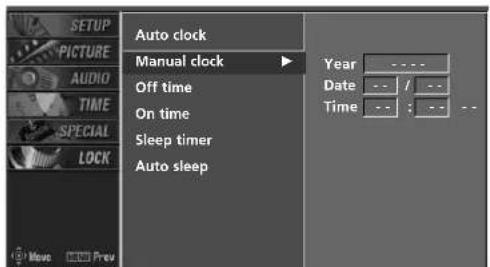
text_image
SETUP PICTURE AUDIO TIME SPECIAL LOCK Auto clock Manual clock Off time On time Sleep timer Auto sleep Year Date Time --- / --- --- : --- --2 3
TV MENU | TIME SETTING
ON/OFF TIME SETUP
The time function operates only if the current time has been set.
The Off-Time function overrides the On-Time function if they are both set to the same time.
The TV must be in standby mode for the On-Time to work. If you do not press any button within 2 hours after the TV turns on with the On Time function, the TV will automatically revert to standby mode.
1 Press the MENU button and then use ▲ or ▼ button to select the TIME menu.
2 Press the ▶ button and then use ▲ or ▼ button to select Off Time or On Time.
3 Press the ▶ button and then use ▲ or ▼ button to select O○nn
■ To cancel the On/Off time function, select Off.
4 Press the ▶ button and then use ▲ or ▼ button to set the hour.
5 Press the ▶ button and then use ▲ or ▼ button to set the minutes.
6 Only On time Press the ▶ button and then use ▲ or ▼ to select the programme at turn-on.
Press the ▶ button and then use ▲ or ▼ to set the sound level at turn-on.
7 Press EXIT button to return to normal TV viewing.
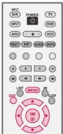
text_image
INPUT D/A POWER TV INPUT ARC VCR TEXT PIP GUIDE INFO LIST MENU VII EXIT SLEEP OK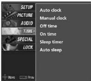
text_image
SETUP PICTURE AUDIO TIME SPECIAL LOCK Auto clock Manual clock Off time On time Sleep timer Auto sleep1
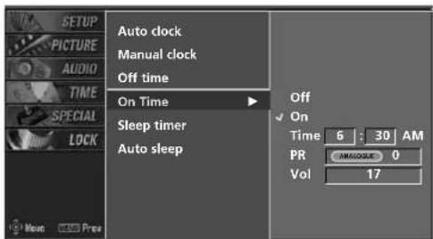
text_image
SETUP PICTURE AUDIO TIME SPECIAL LOCK Auto clock Manual clock Off time On Time Sleep timer Auto sleep Off On Time 6 : 30 AM PR AM/DADEE 0 Vol 172 3 4 5 6
SLEEP TIMER
You don't have to remember to switch the set off before you go to sleep.
The sleep timer automatically switches the set to standby after the preset time has elapsed.
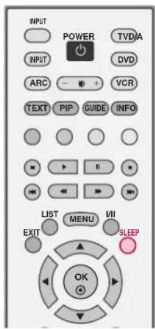
text_image
INPUT POWER TVDIA INPUT DVD ARC VCR TEXT PIP GUIDE INFO LIST MENU VII EXIT SLEEP OK1 Press the SLEEP button repeatedly to select the number of minutes. First the Off option appears on the screen, followed by the following sleep timer options: 10, 20, 30, 60, 90, 120, 180, and 240 minutes.
2 When the number of minutes you want is displayed on the screen, press the SLEEP button. The timer begins to count down from the number of minutes selected.
3 To check the remaining minutes before the TV turns off, press the SLEEP button once.
4 To cancel the Sleep Timer, press the SLEEP button repeatedly to select Off.
5 When you switch the set off, the set release the preset sleep time.
■You can also set up the Sleep timer in the TIME menu.
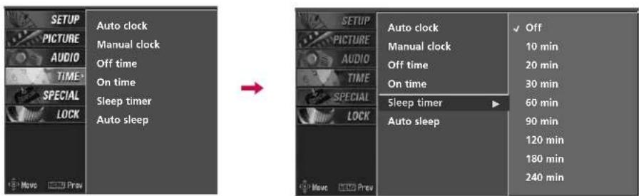
text_image
SETUP PICTURE AUDIO TIME- SPECIAL LOCK Auto clock Manual clock Off time On time Sleep timer Auto sleep → SETUP PICTURE AUDIO TIME- SPECIAL LOCK Auto clock Manual clock Off time On time Sleep timer Auto sleep ✓ Off 10 min 20 min 30 min 60 min 90 min 120 min 180 min 240 minTV MENU | TIME SETTING
AUTO SLEEP
If set to on and there is no input signal, the TV turns off automatically after 10 minutes.
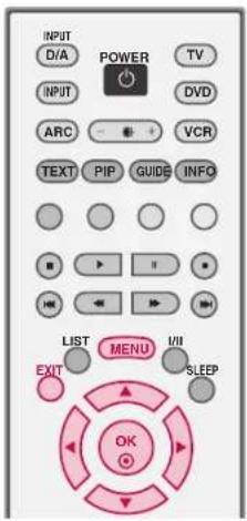
text_image
INPUT D/A POWER TV INPUT ARC VCR TEXT PIP GUIDB INFO LIST MENU I/II EXIT SLEEP OK1 Press the MENU button and then use ▲ or ▼ button to select the TIME menu.
2 Press the ▶ button and then use ▲ or ▼ button to select Auto sleep.
3 Press the ▶ button and then use ▲ or ▼ button to select Off or OQnn
4 Press EXIT button to return to normal TV viewing.
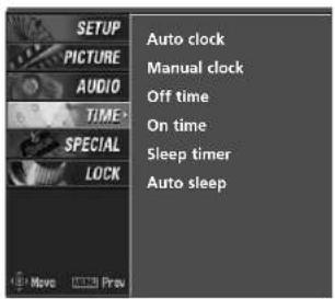
text_image
SETUP PICTURE AUDIO TIME SPECIAL LOCK Auto clock Manual clock Off time On time Sleep timer Auto sleep1
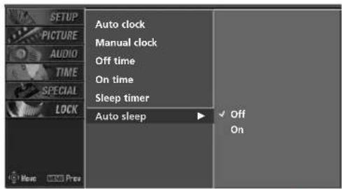
text_image
AUTO clock MANUAL CLOCK OFF time On time Sleep timer Auto sleep Off On2 3
TV MENU | OPTIONAL FEATURES
MAIN PICTURE SOURCE SELECTION
Alternatively you can select the Digital, Analogue, AV1-2, Component 1-2, RGB-PC (or RGB-DTV) or HDMI/DVI mode by pressing the INPUT button.
Press the D/A INPUT button to select digital or analogue mode.
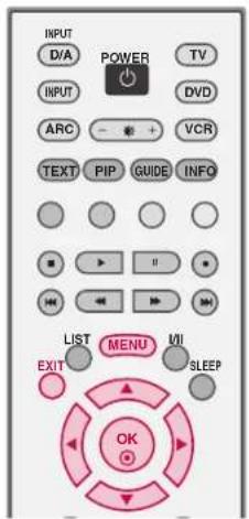
text_image
INPUT D/A POWER TV INPUT ARC - * + VCR TEXT PIP GUIDE INFO LIST MENU VII EXIT SLEEP OK1 Press the MENU button and then use ▲ or ▼ button to select the SPECIAL menu.
2 Press the ▶ button and then use ▲ or ▼ button to select Main input.
3 Press the ▶ button and then use ▲ or ▼ to select Digital, Analogue, AV 1, AV 2, Component 1, Component 2, RGB-PC, RGB-DTV, or HDMI/DVI.
■ To toggle RGB-DTV and RGB-PC, select RGB-DTV(or RGB-PC) and press ▶ button.
4 Press EXIT button to return to normal TV viewing.
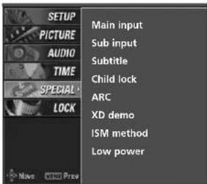
text_image
SETUP PICTURE AUDIO TIME SPECIAL LOCK Main input Sub input Subtitle Child lock ARC XD demo ISM method Low power1
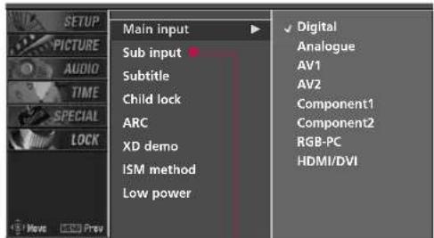
text_image
SETUP PICTURE AUDIO TIME SPECIAL LOCK Main input Sub input Subtitle Child lock ARC XD demo ISM method Low power ✓ Digital Analogue AV1 AV2 Component1 Component2 RGB-PC HDMI/DVI2 3
Sub Picture Source Selection
Select sources for the Sub Input in the SPECIAL menu.
See Page 37 for selecting the input source for the sub picture by pressing the PIP INPUT button.
TV MENU | OPTIONAL FEATURES
SUBTITLE - In Digital Mode only
You can select Subtitle on or off with the TEXT button in DTV mode.
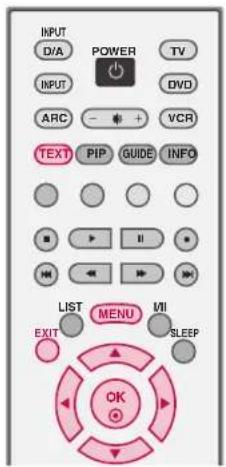
text_image
INPUT D/A POWER TV INPUT ARC - + VCR TEXT PIP GUIDE INFO LIST MENU VII EXIT SLEEP OK1 Press the MENU button and then use ▲ or ▼ button to select the SPECIAL menu.
2 Press the ▶ button and then use ▲ or ▼ button to select Subtitle.
3 Press the ▶ button and then use ▲ or ▼ button to select Off or OQ.nn
4 Press EXIT button to return to normal TV viewing.
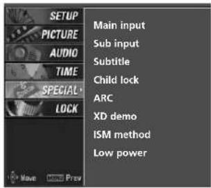
text_image
SETUP PICTURE AUDIO TIME SPECIAL LOCK Main input Sub input Subtitle Child lock ARC XD demo ISM method Low power1
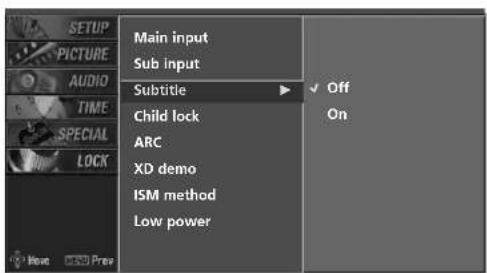
text_image
SETUP PICTURE AUDIO TIME SPECIAL LOCK Main input Sub input Subtitle Child lock ARC XD demo ISM method Low power Off On2 3
CHILD LOCK
The TV can be set so that the remote control is needed to control it. This feature can be used to prevent unauthorized viewing.
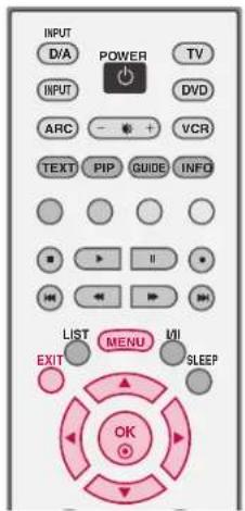
text_image
INPUT D/A POWER TV INPUT ARC - + VCR TEXT PIP GUIDE INFO LIST MENU UI EXIT SLEEP OK1 Press the MENU button and then use ▲ or ▼ button to select the SPECIAL menu.
2 Press the ▶ button and then use ▲ or ▼ button to select Child lock
3 Press the ▶ button and then use ▲ or ▼ button to select Off or OQ.nn
4 Press EXIT button to return to normal TV viewing.
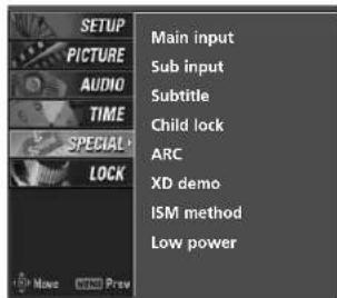
text_image
SETUP PICTURE AUDIO TIME SPECIAL LOCK Main input Sub input Subtitle Child lock ARC XD demo ISM method Low power1
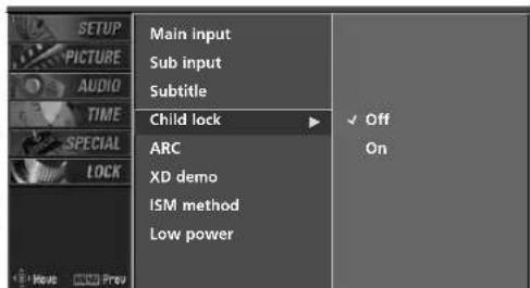
text_image
SETUP PICTURE AUDIO TIME SPECIAL LOCK Main input Sub input Subtitle Child lock ARC XD demo ISM method Low power ✓ Off On2 3
NOTE
With the lock on, the display 'Child lock : On' appears on the screen if any button on the front panel is pressed while viewing the TV.
The display 'Child lock : On' will not appear on the screen if any button on the front panel is pressed while displaying the menus.
TV MENU | OPTIONAL FEATURES
PICTURE FORMAT
You can watch TV in various picture formats; Auto, 4:3, 16:9 (Wide), 14:9, Zoom and Cinema zoom.
NOTE
If a fixed image is displayed on the screen for a long time, it image may become imprinted on the screen and remain visible. This phenomenon is common to all manufactures and in consequence the manufactures warranty does not cover the product bearing this phenomenon.
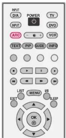
text_image
INPUT D/A POWER TV INPUT DVD ARC - + VCR TEXT PIP GUIDE INFO LIST MENU VII EXIT SLEEP OK1 Press the ARC button repeatedly to select the desired picture format.
■ You can also adjust ARC in the SPECIAL menu.
Auto
Selects the proper picture proportion to match the source's image. (4:3 4:3, 16:9 → 16:9)
4:3
Choose 4:3 when you want to view a picture with an original 4:3 aspect ratio.
16:9
Adjust the picture horizontally, in a linear proportion to fill the entire screen.
14:9
The screen size is, more enlarged at both sides, to create a spectacular view. You can move the 14:9 screen using ▲ or ▼ button. The adjustment range is -10 - +10.
Zoom
Choose Zoom when you want to view the picture without any alteration. However, the top and bottom portions of the picture will be cropped.
You can move the Zoom screen using ▲ or ▼ button. The adjustment range is -16 - +16.
Cinema Zoom
Choose Cinema Zoom when you want to enlarge the picture in correct proportion. Note: When enlarging or reducing the picture, the image may become distorted.
You can adjust the enlarge proportion of Cinema Zoom using ▲ or ▼ button. The adjustment range is 1-16.
NOTE
In HDMI/DVI-PC and RGB-PC mode, 4:3 and 16:9 is available.
▶ Auto: When your TV receives the wide screen signal, it will be automatically changed to the picture format to be sent. (Not available in all countries)
XD DEMO
Allows you to select your preferred picture mode after compairing the four different picture (Dynamic, Standard, Mild, and User1 (or User2)) settings.
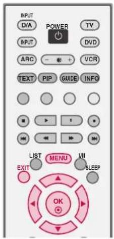
text_image
INPUT D/A POWER TV INPUT DVD ARC VCR TEXT PIP GUIDE INFO LIST MENU VII EXIT SLEEP OK1 Press the MENU button and then use ▲ or ▼ button to select the SPECIAL menu.
2 Press the ▶ button and then use ▲ or ▼ button to select XD demo.
3 Press the ▶ button to start XD demo.
4 Press EXIT button to stop XD demo.
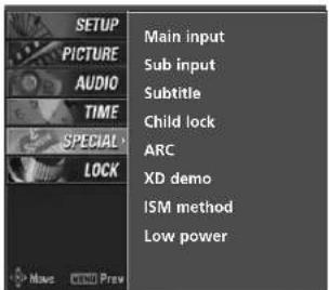
text_image
SETUP PICTURE AUDIO TIME SPECIAL LOCK Main input Sub input Subtitle Child lock ARC XD demo ISM method Low power1
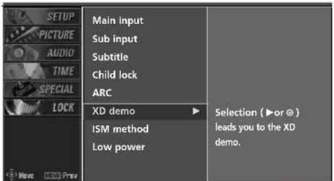
text_image
SETUP PICTURE AUDIO TIME SPECIAL LOCK Main input Sub input Subtitle Child lock ARC XD demo ISM method Low power Selection (►or ⊙) leads you to the XD demo.2 3
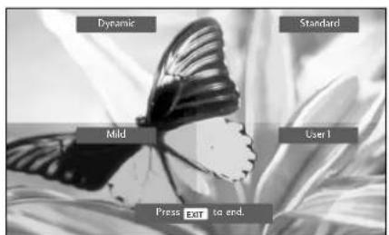
text_image
Dyramic Standard Mild User1 Press EXIT to end.TV MENU | OPTIONAL FEATURES
ISM (Image Sticking Minimization) METHOD
- 42PC1D*, 50PC1D*, 60PC1D*only
A frozen still picture from a PC/video game displayed on the screen for prolonged periods will result in a ghost image. Use our unique method to minimize any fixed image on the screen.
1 Press the MENU button and then use ▲ or ▼ button to select the SPECIAL menu.
2 Press the ▶ button and then use ▲ or ▼ button to select ISM method.
3 Press the ▶ button and then use ▲ or ▼ button to select either Normal, White wash, Orbiter or Inversion.
Normal
If image sticking is never a problem, ISM is not necessary - set to Normal.
Orbiter
Orbiter may help prevent ghost images. However, it is best not to allow any fixed image to remain on the screen. To avoid a permanent image on the screen, the image will move once per 2 minutes.
Inversion
Inversion will automatically invert the plasma display panel color every 30 minutes.
■ White wash
White Wash removes permanent images from the screen.
NOTE
An excessive permanent image may be impossible to clear entirely with White Wash. To return to normal viewing, press any button.
4 Press EXIT button to return to normal TV viewing.
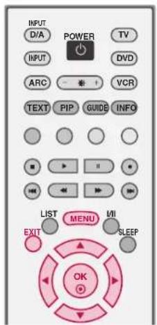
text_image
INPUT D/A POWER TV INPUT ARC VCR TEXT PIP GUIDB INFO LIST MENU VII EXIT SLEEP OK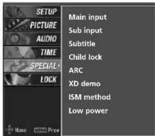
text_image
SETUP PICTURE AUDIO TIME SPECIAL LOCK Main input Sub input Subtitle Child lock ARC XD demo ISM method Low power1
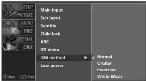
text_image
SETUP PICTURE AUDIO TIME SPECIAL LOCK Main input Sub input Subtitle Child lock ARC XD demo ISM method Low power Normal Orbiter Inversion White Wash2 3
LOW POWER - 42PC1D\*, 50PC1D\*, 60PC1D\*only
Low power reduces the plasma display power consumption.
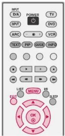
text_image
INPUT D/A POWER TV INPUT ARC VCR TEXT PIP GUIDE INFO LIST MENU EXIT SLEEP OK1 Press the MENU button and then use ▲ or ▼ button to select the SPECIAL menu.
2 Press the ▶ button and then use ▲ or ▼ button to select Low power.
3 Press the ▶ button and then use ▲ or ▼ button to select Off or OQnn
■ When you select O, the screen darkens.
4 Press EXIT button to return to normal TV viewing.
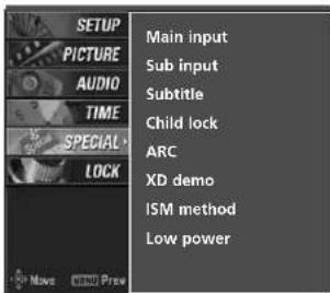
text_image
SETUP PICTURE AUDIO TIME SPECIAL LOCK Main input Sub input Subtitle Child lock ARC XD demo ISM method Low power1
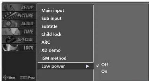
text_image
SETUP PICTURE AUDIO TIME SPECIAL LOCK Main input Sub input Subtitle Child lock ARC XD demo ISM method Low power Off On2 3
TV MENU | LOCK ADJUSTMENT
SETTING UP YOUR PASSWORD
Set up blocking schemes to block specific channels, ratings, and external viewing sources.
A password is required to gain access to this menu.
1
Press the MENU button and then use the ▲ or ▼ button to select the LOCK menu. Then, press the ▶ button.
■ Enter the password as requested.
■ The TV is set up with the initial password "0-0-0-0".
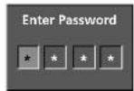
LOCK SYSTEM
Enables or disables the blocking scheme you set up previously.
1
After inputting the password, use the ▲ or ▼ button to choose Lock system.
2
Press the ▶ button and then use the ▲ or ▼ button to select On or Off.
■ When you select On, the Lock System is enable.
3
Press EXIT button to return to normal TV viewing.
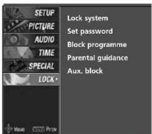
text_image
SETUP PICTURE AUDIO TIME SPECIAL LOCK Lock system Set password Block programme Parental guidance Aux. block1
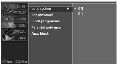
text_image
SETUP PICTURE AUDIO TIME SPECIAL LOCK Lock system Set password Block programme Parental guidance Aux. block Off On2
SET PASSWORD
Change the password by inputting a new password twice.

After inputting the password, use the ▲ or ▼ button to choose Set password.

Press the ▶ button and then choose any 4 digits for your new password next to New.
As soon as the 4 digits are entered, re-enter the same 4 digits on the Confirm. The new password is memorized.

Press EXIT button to return to normal TV viewing.

NOTE
If you ever forget your password, key in '7', '7', '7', '7' on the remote control.
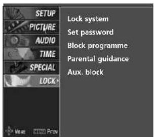
text_image
SETUP PICTURE AUDIO TIME SPECIAL LOCK Lock system Set password Block programme Parental guidance Aux. block1
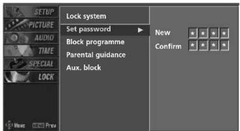
text_image
SETUP PICTURE AUDIO TIME SPECIAL LOCK Lock system Set password Block programme Parental guidance Aux. block New Confirm * * * * * * * * Music ©ND Press2
TV MENU | LOCK ADJUSTMENT
BLOCK PROGRAMME
Select a channel number that you wish to block.
1 After inputting the password, use the ▲ or ▼ button to choose Block programme.
2 Press the ▶ button. You will now see a screen filled with channel numbers and a preview picture.
3 Use ▲▼◀▶ button to select a channel and then use the ○ button to block or unblock it.
4 Press EXIT button to return to TV viewing or press MENU button to return to the previous menu.
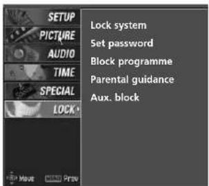
text_image
SETUP PICTURE AUDIO TIME SPECIAL LOCK Lock system Set password Block programme Parental guidance Aux. block1
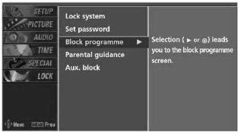
text_image
SETUP PICTURE AUDIO TIME SPECIAL LOCK Lock system Set password Block programme ▶ Selection ( ▶ or @ ) leads you to the block programme screen. Parental guidance Aux. block2
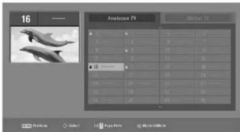
text_image
16 Analyze IV Video IV 1 2 3 4 5 6 7 8 9 10 11 12 13 14 15 16 17 18 19 20 21 22 23 24 25 26 27 28 29 30 31 32 33 34 35 36 37 38 39 40 41 42 43 44 45 46 47 48 49 50 51 52 53 54 55 56 57 58 59 60 61 62 63 64 65 66 67 68 69 70 71 72 73 74 75 763
PARENTAL GUIDANCE -In Digital Mode only
Prevents children from watching certain children's TV programs, according to the ratings limit set.
1 After inputting the password, use the ▲ or ▼ button to choose Parental guidance.
Press the ▶ button and then use the ▲ or ▼ to select G,PP,CM, M A,A,A √R
■ G (General audience)
■ PG (Parental guidance suggested)
■ M (Mature audiences)
■ MA (Mature adult audiences)
■ AV (Adult audiences)
■ R (Restricted)
■ Blocking Off (Permits all programs)
3 Press EXIT button to return to normal TV viewing.
AUX. BLOCK
Enables you to select a source to block from the external source devices you have hooked up.
1 After inputting the password, use the ▲ or ▼ button to choose Aux. block.
2 Press the ▶ button and then use the ◀ or ▶ button to select a source.
3 Press the ▶ button and then use the ▲ or ▼ button to select O○ on Off on the each source.
4 Press EXIT button to return to normal TV viewing.
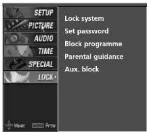
text_image
SETUP PICTURE AUDIO TIME SPECIAL LOCK> Lock system Set password Block programme Parental guidance Aux. block1
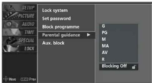
text_image
SETUP PICTURE AUDIO TIME SPECIAL LOCK Lock system Set password Block programme Parental guidance ▶ Aux. block G PG M MA AV R Blocking Off2
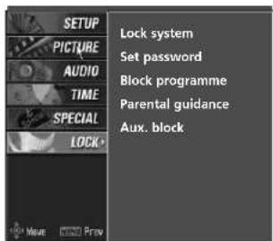
text_image
SETUP PICTURE AUDIO TIME SPECIAL LOCK Lock system Set password Block programme Parental guidance Aux. block1
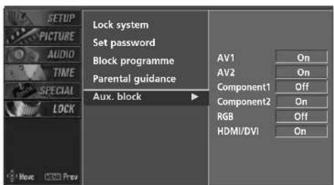
text_image
SETUP PICTURE AUDIO TIME SPECIAL LOCK Lock system Set password Block programme Parental guidance Aux. block AV1 On AV2 On Component1 Off Component2 On RGB Off HDMI/DVI On2 3
APPENDIX
EXTERNAL CONTROL DEVICE SETUP
Connect the RS-232C (serial port) input jack to an external control device (such as a computer or an A/V control system) to control the TV's functions externally.
Note: RS-232C connection cables are not supplied with the TV.
RS-232C Setup
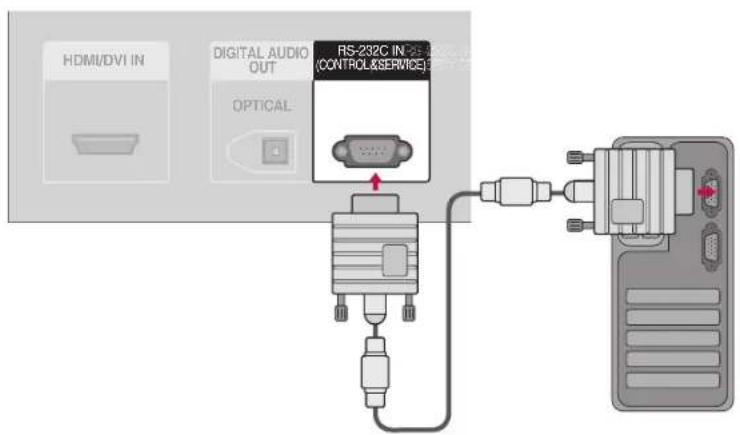
text_image
HDMI/DVI IN DIGITAL AUDIO OUT OPTICAL RS-232C IN-25 (CONTROL&SERVICE)Type of Connector; D-Sub 9-Pin Male
No. Pin Name
1 No connection
2 RXD (Receive data)
3 TXD (Transmit data)
4 DTR (DTE side ready)
5 GND
6 DSR (DCE side ready)
7 RTS (Ready to send)
8 CTS (Clear to send)
9 No Connection
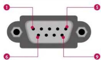
text_image
Diagram of a V124 port with numbered pins pointing to specific portsRS-232C Configurations
7-Wire Configurations (Standard RS-232C cable)
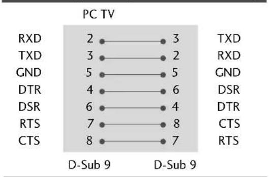
line
PC TV | Signal | D-Sub 9 | D-Sub 9 | | :--- | :--- | :--- | | RXD | 2 | 3 | | TXD | 3 | 2 | | GND | 5 | 5 | | DTR | 4 | 6 | | DSR | 6 | 4 | | RTS | 7 | 8 | | CTS | 8 | 7 | TXD RXD GND DSR DTR CTS RTS3-Wire Configurations(Not standard)
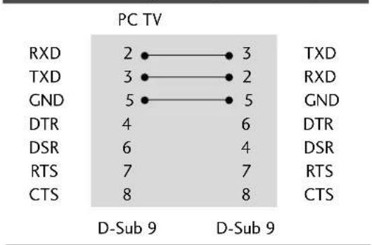
line
PC TV | Category | PC TV | | :--- | :--- | | RXD | 2 | | TXD | 3 | | GND | 5 | | DTR | 4 | | DSR | 6 | | RTS | 7 | | CTS | 8 | TXD | 3 | | RXD | 2 | | GND | 5 | | DTR | 6 | | DSR | 4 | | RTS | 7 | | CTS | 8 | D-Sub 9 D-Sub 9Set ID
Use this function to specify a TV ID number.
Refer to 'Real Data Mapping1'. See page 89.
1 Press the MENU button and then use ▲ or ▼ button to select the SETUP menu.
2 Press the ▶ button and then use ▲ or ▼ button to select Set ID.
3 Press the ▶ button and then use ▲ or ▼ button to adjust Set ID to choose the desired TV ID number. The adjustment range of Set ID is 1\~99.
4 Press EXIT button to return to TV viewing or press MENU button to return to the previous menu.
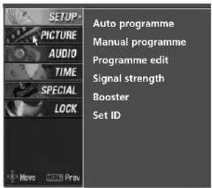
text_image
AUTO programme MANUAL PROGRAMME PROGRAMME edit Signal strength Booster Set ID①
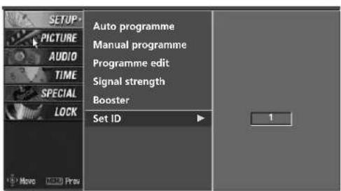
text_image
SETUP PICTURE AUDIO TIME SPECIAL LOCK Auto programme Manual programme Programme edit Signal strength Booster Set ID 12 3
Communication Parameters
■ Baud rate : 9600 bps (UART)
■ Data length : 8 bits
■ Parity : None
■ Stop bit : 1 bit
■ Communication code : ASCII code
■ Use a crossed (reverse) cable.
APPENDIX
Command Reference List
| COMMAND1 | COMMAND2 | DATA (Hexadecimal) | COMMAND1 | COMMAND2 | DATA (Hexadecimal) | ||
| 01. Power | k | a | 0 ~ 1 | 17. Bass | k | s | 0 ~ 64 |
| 02. Input Select | k | b | 0 ~ 8 | 18. Balance | k | t | 0 ~ 64 |
| 03. Aspect Ratio | k | c | See p.89 | 19. Colour Temperature | k | u | 0 ~ 2 |
| 04. Screen Mute | k | d | 0 ~ 1 | 20. Red Adjustment | k | v | 0 ~ C8 |
| 05. Volume Mute | k | e | 0 ~ 1 | 21. Green Adjustment | k | w | 0 ~ C8 |
| 06. Volume Control | k | f | 0 ~ 64 | 22. Blue Adjustment | k | $ | 0 ~ C8 |
| 07. Contrast | k | g | 0 ~ 64 | 23. PIP Input Source | k | y | 0 ~ 3 |
| 08. Brightness | k | h | 0 ~ 64 | 24. ISM Method | j | p | 0 ~ 3 |
| 09. Colour | k | i | 0 ~ 64 | 25. Low Power | j | q | 0 ~ 1 |
| 10. Tint | k | j | 0 ~ 64 | 26. Orbiter Time Setting | j | r | 1 ~ FE |
| 11. Sharpness | k | k | 0 ~ 64 | 27. Orbiter Pixel Setting | j | s | 1 ~ 3 |
| 12. OSD Select | k | l | 0 ~ 1 | ||||
| 13. Remote Control/ Key Lock | k | m | 0 ~ 1 | 28. Channel Tuning | m | a | See p.91 |
| 29. Send IR Code | m | c | See p.92 | ||||
| 14. PIP/POP/Twin | k | n | 0 ~ 3 | 30. Input Select | x | b | See p.92 |
| 15. PIP Position | k | q | 0 ~ 3 | 31. PIP Input Select | x | y | See p.92 |
| 16. Treble | k | r | 0 ~ 64 |
Only 42PC1D*, 50PC1D*, 60PC1D* models
Transmission / Receiving Protocol
Transmission
[Command1][Command2][ ][Set ID][ ][Data][Cr]
[Command 1]: First command to control the set. (j, k, m or x)
[Command 2]: Second command to control the set.
[Set ID] : You can adjust the selDtochoosedesired TV ID number in Setup menu. Adjustment range is 1 \~ 99. When selecting Set ID '0', every connected the TV is controlled. Set ID is indicated as decimal (1 \~ 99) on menu and as Hexa decimal (0x0 \~ 0x63) on transmission/receiving protocol.
[DATA] : To transmit command data. Transmit 'FF' data to read status of command.
[Cr] : Carriage Return ASCII code '0x0D' [ ] : ASCII code 'space (0x20)'
OK Acknowledgement
[Command2][ ][Set ID][ ][OK][Data][x]
The TV transmits ACK (acknowledgement) based on this format when receiving normal data. At this time, if the data is data read mode, it indicates present status data. If the data is data write mode, it returns the data of the PC computer.
Error Acknowledgement
[Command2][ ][Set ID][ ][NG][Data][x]
The TV transmits ACK (acknowledgement) based on this format when receiving abnormal data from non-viable functions or communication errors.
Data1: Illegal Code
Data2: Not supported function
Data3: Wait more time
01. Power (Command2:a)
To control Power On/Off of the TV.
Transmission [k][a][ ][Set ID][ ][Data][Cr]
Data 0 : Power Off Data 1 : Power On
Acknowledgement [a][ ][Set ID][ ][OK/NG][Data][x]
* In a like manner, if other functions transmit 'FF' data based on this format, Acknowledgement data feedback presents status about each function.
02. Input Select (Command2:b) (Main Picture Input)
To select input source for the TV.
Transmission [k][b][ ][Set ID][ ][Data][Cr]
Data 0: Digital Data 5: Component 2
Data 1: Analogue Data 6: RGB-DTV
Data 2: AV1 Data 7: RGB-PC
Data 3: AV2 Data 8: HDMI/DVI
Data 4: Component 1
Acknowledgement [b][ ][Set ID][ ][OK/NG][Data][x]
03. Aspect Ratio (Command2:c) (Main picture format)
To adjust the screen format.
You can also adjust the screen format using the ARC button on remote control or in the Special menu.
Transmission [k][c][ ][Set ID][ ][Data][Cr]
Date 0: Auto
1:4:3
2:16:9
04. Screen Mute (Command2:d)
To select screen mute on/off.
Transmission [k][d][ ][Set ID][ ][Data][Cr]
Data 0 : Screen mute off (Picture on)
Data 1: Screen mute on (Picture off)
Acknowledgement [d][ ][Set ID][ ][OK/NG][Data][x]
05. Volume Mute (Command2:e)
To control volume mute on/off.
You can also adjust mute using the MUTE button on remote control.
Transmission [k][e][ ][Set ID][ ][Data][Cr]
Data 0 : Volume mute off (Volume on)
Data 1 : Volume mute on (Volume off)
Acknowledgement [e][ ][Set ID][ ][OK/NG][Data][x]
06. Volume Control (Command2:f)
To adjust volume.
You can also adjust volume with the volume buttons on remote control.
Transmission [k][f][ ][Set ID][ ][Data][Cr]
Data Min: 0 \~ Max: 64
Refer to 'Real data mapping1' as shown below.
Acknowledgement [f] || Set ID || [OK/NG][Data][x]
07. Contrast (Command2:g)
To adjust screen contrast.
You can also adjust contrast in the Picture menu.
Transmission [k][g][ ][Set ID][ ][Data][Cr]
Data Min: 0 \~ Max: 64
Refer to 'Real data mapping1' as shown below.
Acknowledgement [g][ ][Set ID][ ][OK/NG][Data][x]
08. Brightness (Command2:h)
To adjust screen brightness.
You can also adjust brightness in the Picture menu.
Transmission [k][h][ ][Set ID][ ][Data][Cr]
Data Min : 0 \~ Max : 64(*transmit by Hexadecimal code)
Refer to 'Real data mapping1' as shown below.
Acknowledgement [h][ ] [Set ID][ ][OK/NG][Data][x]
09. Colour (Command2:i)
To adjust the screen colour.
You can also adjust colour in the Picture menu.
Transmission [k][i][ ][Set ID][ ][Data][Cr]
Data Min: 0 \~ Max: 64
Refer to 'Real data mapping1' as shown below.
Acknowledgement [i][ ][Set ID][ ][OK/NG][Data][x]
*Real data mapping 1
0:Step 0
• • • •
A: Step 10 (SET ID 10)
• • • •
F: Step 15 (SET ID 15)
10:Step 16 (SET ID 16)
......
63:Step 99 (SET ID 99)
64:Step 100
Tint: R50 \~ G50, Balance: L50 \~ R50
APPENDIX
10. Tint (Command2:j)
To adjust the screen tint (only 60Hz).
You can also adjust tint in the Picture menu.
Transmission [k][j][ ][Set ID][ ][Data][Cr]
Data Red: 0 \~ Green: 64
*Refer to 'Real data mapping1'. See page 89.
Acknowledgement [j][ ][Set ID][ ][OK/NG][Data][x]
11. Sharpness (Command2:k)
To adjust the screen sharpness.
You can also adjust sharpness in the Picture menu.
Transmission [k][k][ ][Set ID][ ][Data][Cr]
Data Min: 0 \~ Max: 64
*Refer to 'Real data mapping1'. See page 89.
Acknowledgement [k][ ][Set ID][ ][OK/NG][Data][x]
12. OSD Select (Command2:1)
To select OSD (On Screen Display) on/off.
Transmission [k][l][ ][Set ID][ ][Data][Cr]
Data 0: OSD off
Data 1: OSD on
Acknowledgement [I][ ] [Set ID][ ] [OK/NG][Data][x]
* When setting "OSD - Off", every OSD doesn't display on screen.
13. Remote Control Lock Mode (Command2:m)
To lock the remote control and the front panel controls on the set.
Transmission [k][m][ ][Set ID][ ][Data][Cr]
Data 0: Lock off
Data 1: Lock on
Acknowledgement [m][ ][Set ID][ ][OK/NC][Data][x]
14. PIP / POP / Twin Picture (Command2:n)
To control the PIP (Picture-in-Picture)/POP/Twin picture. You can also control the PIP/POP/Twin picture using the PIP button on the remote control.
Transmission [k][n][ ][Set ID][ ][Data][Cr]
Data 0: PIP off
2: POP
1: PIP
3: Twin picture
Acknowledgement [n][ ][Set ID][ ][OK/NG][Data][x]
15. PIP Position (Command2:q)
To select sub picture position for PIP.
Transmission [k][q][ ][Set ID][ ][Data][Cr]
Data 0: Right down on screen
Data 1: Right up on screen
Data 2: Left up on screen
Data 3: Left down on screen
Acknowledgement [q][ ][Set ID][ ][OK/NG][Data][x]
16. Treble (Command2:r)
To adjust treble.
You can also adjust treble in the Audio menu.
Transmission [k][r][ ][Set ID][ ][Data][Cr]
Data Min: 0 \~ Max: 64(*transmit by Hexadecimal code)
*Refer to 'Real data mapping1'. See page 89.
Acknowledgement [r][ ][Set ID][ ][OK/NG][Data][x]
17. Bass (Command2:s)
To adjust bass.
You can also adjust bass in the Audio menu.
Transmission [k][s][ ][Set ID][ ][Data][Cr]
Data Min: 0 \~ Max: 64(*transmit by Hexadecimal code)
*Refer to 'Real data mapping1'. See page 89.
Acknowledgement [s][ ][Set ID][ ][OK/NG][Data][x]
18. Balance (Command2:t)
To adjust balance.
You can also adjust balance in the Audio menu.
Transmission [k][t][ ][Set ID][ ][Data][Cr]
Data Min: 0 \~ Max: 64(*transmit by Hexadecimal code)
*Refer to 'Real data mapping1'. See page 89.
Acknowledgement [t][ ][Set ID][ ][OK/NG][Data][x]
19. Colour Temperature (Command2: u)
To adjust colour temperature.
You can also adjust colour temperature in the Picture menu.
Transmission [k][u][ ][Set ID][ ][Data][Cr]
Data 0: Medium 1: Cool 2: Warm 3: User
Acknowledgement [u][ ][Set ID][ ][OK/NG][Data][x]
To adjust red in color temperature
Transmission [k][v][ ][Set ID][ ][Data][Cr]
Data Min:0 \~ Max:C8
*Refer to "Real data mapping 2". See page 91.
Acknowledgement [v][ ] [Set ID][ ] [OK/NG][Data][x]
21. Green Adjustment(Command:w)
To adjust green in colour temperature.
Transmission [k][w][ ][Set ID][ ][Data][Cr]
Data Min:0 \~ Max:C8
*Refer to "Real data mapping 2" as shown below
Acknowledgement [w][ ][Set ID][ ][OK/NG][Data][x]
To adjust blue in colour temperature.
Transmission [k] [\$][ ] [Set ID][ ][Data][Cr]
Data Min:0 \~ Max:C8
*Refer to "Real data mapping 2" as shown below
Acknowledgement [\$][ ][Set ID][ ][OK/NG][Data][x]]
*Real data mapping 2
0:-20
5:-19
A:-18
• • •
5F: -1
64:0
69:+1
• • • •
C3: +19
C8:+20
23. PIP Input Select (Command2:y)
To select input source for sub picture in PIP/Twin picture mode. You can also adjust input source for sub picture using PIP INPUT button remote control.
Transmission [k][y][ ][Set ID][ ][Data][Cr]
Data 0: Digital
Data 2: AV1
Data 1: Analogue
Data 3: AV2
Acknowledgement [y][ ][Set ID][ ][OK/NG][Data][x]
24. ISM Method (Command2:p)
(Only 42PC1D*/50PC1D*/60PC1D* models)
To control the ISM method. You can also adjust ISM method in Special menu.
Transmission [j][p][ ][Set ID][ ][Data][Cr]
Data 0: Normal
Data 1: Orbiter
Data 2: Inversion
Data 3: White Wash
Acknowledgement [p][ ][Set ID][ ][OK/NG][Data][x]
25. Low Power (Command2:q)
(Only 42PC1D*/50PC1D*/60PC1D* models)
To reduce the power consumption of the set. You can also adjust Low power in Special menu.
Transmission [j][q][ ][Set ID][ ][Data][Cr]
Data 0: low power off
1: low power on
Acknowledgement [q][ ][Set ID][ ][OK/NG][Data][x]
26. Orbiter Time Setting (Command2:r)
(Only 42PC1D*/50PC1D*/60PC1D* models)
To adjust orbiter operation time term.
Transmission [j][r][ ][Set ID][ ][Data][Cr]
Data Min: 1 \~ Max: FE(*transmit by Hexadecimal code),
Unit: Second
*Refer to 'Real data mapping1'. See page 89.
Acknowledgement [r][ ][Set ID][ ][OK/NG][Data][x]
27. Orbiter Pixel Setting (Command2:s)
(Only 42PC1D*/50PC1D*/60PC1D* models)
To adjust pixel number in orbiter function.
Transmission [j][s][ ][Set ID][ ][Data][Cr]
Data Min: 1 \~ Max: 3
*Refer to 'Real data mapping1'. See page 89.
Acknowledgement [s][ ][Set ID][ ][OK/NG][Data][x]
28. Channel Tuning (Command: m a)
To tune channel to following programme number
Transmission [m][a][ ][Set ID][ ][Data0][ ][Data1]
[ ] [Data2] [Cr]
Data 0: High channel data
Data 1: Low channel data
Data 2: 00: Analogue TV Main
: 01: Analogue TV Sub
: 10: Digital Main
: 11: Digital Sub
ex) Analogue TV Main: ma 0 00 01 00
Digital Sub: ma 0 00 0A 11
* Channel Data Range:
Analogue TV: 0 \~ 63
Digital TV: 0 \~ 3E7
APPENDIX
29. Send IR Code (Command: m c)
To send IR remote key code
Transmission[m][c][ ][Set ID][ ][Data][Cr]
Data Key code: Refer to page 94.
Acknowledgement[c][ ][Set ID][ ][OK/NG][Data][x]
* In this function, It's unavailable to use the IR Code "08 (Power)" and C4 (Power On)".
30. Input Select(Command: x b) (Main Picture Input)
To select input source for main picture.
Transmission[x][b][Set ID][Data][Cr]
Data 00 : Digital Data 41 : Component2
Data 10 : Analogue Data 50 : RGB-DTV
Data 20 : AV1 Data 60 : RGB-PC
Data 21:AV2 Data 90:HDMI/DVI
Data 40 : Component1
Acknowledgement[b][ ][Set ID][ ][OK/NG][Data][x]
31. PIP Input Select(Command: x y)
To select the input source for sub picture in PIP mode.
Transmission[x][y][ ][Set ID][ ][Data][Cr]
Data 00 : Digital
Data 10: Analogue
Data 20:AV1
Data 21 : Av2
Acknowledgement[y][Set ID][OK/NG][Data][x]
IR CODES
1. How to Connect
■ Connect your wired remote control to the Remote Control port on the TV.
2. Remote Control IR Codes
■ Output waveform
Single pulse, modulated with 37.917KHz signal at 455KHz
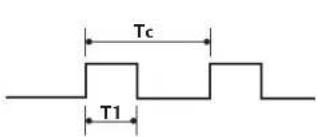
text_image
Tc T1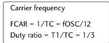
text_image
Carrier frequency FCAR = 1/TC = fOSC/12 Duty ratio = T1/TC = 1/3■ Configuration of frame
1st frame

text_image
Lead code Low custom code High custom code Data code Data code C0 C1 C2 C3 C4 C5 C6 C7 C0 C1 C2 C3 C4 C5 C6 C7 D0 D1 D2 D3 D4 D5 D6 D7 D0 D1 D2 D3 D4 D5 D6 D7Repeat frame

text_image
Repeat code TfLead code

text_image
9 ms 4.5 ms■ Repeat code

text_image
0.55 ms 9 ms 2.25 ms■ Bit description
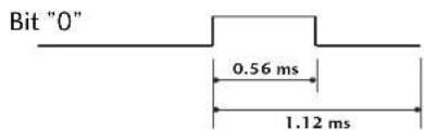
text_image
Bit "0" 0.56 ms 1.12 ms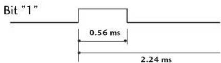
text_image
Bit "1" 0.56 ms 2.24 ms■ Frame interval: Tf
The waveform is transmitted as long as a key is depressed.

text_image
Tf Tf Tf=108ms @455KHzAPPENDIX
| Code (Hexa) | Function Note | Code (Hexa) | Function Note | ||
| 50 | D/A INPUT | Remote control Button | D6 TV Discrete IR Code | ||
| 0B INPUT | Remote control Button | (TV Input Selection) | |||
| 08 | POWER | Remote control Button (Power On/Off) | 5A | AV1 | Discrete IR Code |
| 79 | ARC | Remote control Button | (AV1 Input Selection) | ||
| 0E | SLEEP | Remote control Button | D0 AV2 | Discrete IR Code | |
| 10-19 | Number Key 0-9 | Remote control Button | (AV2 Input Selection) | ||
| 1A Q.VIEW | Remote control Button | BF | COMPONENT1 | Discrete IR Code | |
| 09 MUTE | Remote control Button | (Component1 Input Selection) | |||
| 02 | VOL + | Remote control Button | D4 COMPONENT2 | Discrete IR Code | |
| 03 | VOL - | Remote control Button | (Component2 Input Selection) | ||
| 00 | PR + | Remote control Button | D5 RGB-PC Discrete IR Code | ||
| 01 | PR - | Remote control Button | (RGB-PC Input Selection) | ||
| 1E | FAV | Remote control Button | D7 RGB-DTV Discrete IR Code | ||
| 40 | ▲ | Remote control Button | (RGB-DTV Input Selection) | ||
| 41 | ▼ | Remote control Button | C6 HDMI/DVI | Discrete IR Code | |
| 07 | ◀ | Remote control Button | (HDMI/DVI Input Selection) | ||
| 06 | ▶ | Remote control Button | 76 | Ratio 4:3 | Discrete IR Code |
| 44 OK | Remote control Button | (Only 4:3 Mode) | |||
| 43 | MENU | Remote control Button | 77 | Ratio 16:9 | Discrete IR Code |
| 5B EXIT | Remote control Button | (Only 16:9 Mode) | |||
| 60 PIP | Remote control Button | AF Ratio Zoom | Discrete IR Code | ||
| C1 | PIP PR - | Remote control Button | (Only Zoom Mode) | ||
| C0 PIP PR + | Remote control Button | C4 POWER ON | Discrete IR Code | ||
| C2 SWAP | Remote control Button | (Only Power On) | |||
| C3 PIP INPUT | Remote control Button | C5 POWER OFF Discrete IR Code | |||
| 92 | APM | Remote control Button | (Only Power Off) | ||
| A9 GUIDE | Remote control Button | 53 | LIST | Remote control Button | |
| 64 | SIZE | Remote control Button | 0A | I/II | Remote control Button |
| 70 | INDEX | Remote control Button | AA | INFO | Remote control Button |
| 26 | TIME | Remote control Button | E1 | - | Remote control Button |
| 2A REVEAL | Remote control Button | E0 | + | Remote control Button | |
| 20 | TEXT | Remote control Button | |||
| 72 | RED Remote control Button | ||||
| 71 | GREEN | Remote control Button | |||
| 63 | YELLOW | Remote control Button | |||
| 61 | BLUE | Remote control Button | |||
PROGRAMMING THE REMOTE CONTROL
The remote is a multi-brand or a universal remote. It can be programmed to operate most remote-controllable devices of other manufacturers.
Note that the remote may not control all models of other brands.
Programming a code into a remote mode
To find out whether your remote can operate the device without programming, turn on the device such as a VCR and press the corresponding mode button on the remote.
After that, press the POWER button. If the device is turned off then it responds properly and the remote need not to be programmed. If not, the remote should be programmed to operate the device. The programming procedures are explained below.
2 Press the MENU and MUTE button continuously at the same time for 2 seconds, the current selected device button will be illuminated.
If you don't press any button for 20 seconds, the light on the mode button will be turned off. In that case, you have to repeat from step 2.
3 Enter code numbers using the number button on the remote by referring the code table on the following pages. When pressing the button, the light blinks at a time. If the device turned off, the programming is successful.
4 Press the MENU button to store the code. After blinking twice, this code is stored.
5 Test the remote functions to see if the device responds properly. If not, repeat from step 2.
APPENDIX
PROGRAMMING CODES
VCRs
| Brand Codes Brand Codes Brand Codes | |||||||||
| AIWA 034 | MAGNAVOX | 031 033 034 041 | SAMSUNG | 032 040 102 104 | |||||
| AKAI016043046124 | 067 068 | 105 107 109 112 | |||||||
| 125146 | MARANTZ | 012031033067 | 113 115 120 122 | ||||||
| AMPRO 072 | 069 | 125 | |||||||
| ANAM 031 033 103 | MARTA 101 | SANSUI | 022 043 048 135 | ||||||
| AUDIO DYNAMICS | 012 023039043 | MATSUI | 027 030 | SANYO | 003 007010014 | ||||
| BROKSONIC | 035 037 129 | MEI | 031 033 | 102 134 | |||||
| CANON | 028 031 033 | MEMOREX | 003 010014031 | SCOTT | 017 037 112 129 | ||||
| CAPEHART | 108 | 033 034 053 072 | 131 | ||||||
| CRAIG | 003 040 135 | 101 102 134139 | SEARS 003 008 009 010 | ||||||
| CURTIS MATHES | 031 033 041 | MGA | 045 046 059 | 013 014 017 020 | |||||
| DAEWOO | 005 007010064 | MINOLTA | 013 020 | 031 042 073 081 | |||||
| 065 108 110 111 | MITSUBISHI | 013 020 045 046 | 101 | ||||||
| 112 116 117 119 | 049 051 059 061 | SHARP 031 054 149 | |||||||
| DAYTRON | 108 | 151 | SHINTOM | 024 | |||||
| DBX | 012023039 043 | MTC 034 040 | SONY | 003 009 031 052 | |||||
| DYNATECH | 034 053 | MULTITECH | 024 034 | 056 057 058 076 | |||||
| ELECTROHOME | 059 | NEC | 012023039 043 | 077 078 149 | |||||
| EMERSON | 006 017025 027 | 048 | SOUNDESIGN | 034 | |||||
| 029 031 034 035 | NORDMENDE | 043 | STS | 013 | |||||
| 036037046101 | OPTONICA | 053 054 | SYLVANIA | 031 033 034 059 | |||||
| 129 131 138 153 | PANASONIC | 066 070 074 083 | 067 | ||||||
| FISHER | 003 008 009 010 | 133 140145 | SYMPHONIC | 034 | |||||
| FUNAI 034 | TANDY 010 034 | ||||||||
| GE | 031 033 063 072 | PENTAX | 013 020 031 033 | TATUNG | 039 043 | ||||
| 107 109 144 147 | 063 | TEAC 034 039 043 | |||||||
| GO VIDEO | 132 136 | PHILCO | 031 034 067 | TECHNICS | 031 033 070 | ||||
| HARMAN KARDON | 012045 | PHILIPS 031 033 034 054 | TEKNIKA | 019 031 033 034 | |||||
| HITACHI | 004 018 026 034 | 067 071 101 | 101 | ||||||
| 043 063 137 150 | PILOT | 101 | THOMAS | 034 | |||||
| INSTANTREPLAY | 031 033 | PIONEER | 013 021 048 | TMK | 006 | ||||
| JCL | 031 033 | PORTLAND | 108 | TOSHIBA | 008 013 042 047 | ||||
| JCPENNY | 012013015033 | PULSAR | 072 | 059 082 112 131 | |||||
| 040 066 101 | QUARTZ | 011 014 | TOTEVISION | 040 101 | |||||
| JENSEN 043 | QUASAR | 033 066 075 145 | UNITECH | 040 | |||||
| JVC | 012031033 043 | RCA | 013 020 033 034 | VECTOR RESEARCH | 012 | ||||
| 048 050 055 060 | 040 041 062 063 | VICTOR | 048 | ||||||
| 130150152 | 107 109 140 144 | VIDEO CONCEPTS | 012 034 046 | ||||||
| KENWOOD | 014034 039 043 | 145 147 | VIDEOSONIC | 040 | |||||
| 047 048 | REALISTIC | 003 008 010 014 | WARDS 003 013 017 024 | ||||||
| LG (GOLDSTAR) | 001 012 013 020 | 031 033 034 040 | 031 033 034 040 | ||||||
| 101 106 114 123 | 053 054 101 | 053 054 131 | |||||||
| LLOYD | 034 | RICO 058 | YAMAHA | 012 034 039 043 | |||||
| LXI | 003 009 013 014 | RUNCO | 148 | ZENITH | 034 048 056 | ||||
| 017 034 101 106 | SALORA | 014 | 058 072 080 101 | ||||||
| MAGIN | 040 | ||||||||
VCRs
| Brand Codes Brand Codes Brand Codes | ||||||||||||||
| ABC 003 004 039 | 042 | 074 | REMBRANT | 025 | ||||||||||
| 046 052 053 | LG (GOLDSTAR) | 001 | 106 | 101 | 005 | SAMSUNG | 102 | 107 | 030 | 068 | ||||
| AJIN112 | M-NET | 037 | SCIENTIFIC ATLANTA | 003 | 011 | 041 | 042 | |||||||
| ANTRONIK014 | MACOM | 033 | 043 | 045 | 046 | |||||||||
| ARCHER005 007 | 014 024 | MAGNAVOX | 010 | 012 | 064 | 079 | SHERITECH | 022 | ||||||
| CABLE STAR 026 | MEMOREX | 100 | SIGNAL | 030 | ||||||||||
| CENTURION 092 | MOVIE TIME | 028 | 032 | SIGNATURE | 052 | |||||||||
| CENTURY | 007 | NSC | 015 | 028 | 038 | 071 | SL MARX | 030 | ||||||
| CITIZEN | 007 | 073 | SPRUCER | 047 | 078 | |||||||||
| COLOUR VOICE | 065 090 | OAK | 016 | 031 | 037 | 053 | STARCOM | 002 | 004 | 008 | 009 | |||
| COMBANO | 080 081 | PANASONIC | 044 | 047 | STARGATE | 008 | 030 | |||||||
| COMTRONICS | 019 030 | PARAGON | 100 | TADIRAN | 030 | |||||||||
| DIAMOND | 023 | TAEKWANG | 110 | |||||||||||
| EAGLE | 020 030 040 | PHILIPS | 006 | 012 | 013 | 020 | TAIHAN | 105 | ||||||
| EASTERN | 057 062 066 | 065 | 085 | 090 | TANDY | 017 | ||||||||
| ELECTRICORD | 032 | PIONEER | 034 | 051 | 052 | 063 | TEXSCAN | 029 | ||||||
| GE | 072 | 076 | TOCOM | 039 | 040 | 056 | ||||||||
| GEMINI | 008 022 025 054 | POST NEWS WEEK | 016 | TOSHIBA | 100 | |||||||||
| GI | 052 074 | PRUCER | 059 | UNIKA | 007 | 014 | 024 | |||||||
| GOLDEN CHANNEL | 030 | PTS | 011 | 048 | 071 | 072 | UNITED CABLE | 004 | 053 | |||||
| HAMLIN | 049 050 055 | 073 | 074 | UNIVERSAL | 005 | 007 | 014 | 024 | ||||||
| HITACHI | 052 055 | PULSAR | 100 | 026 | 027 | 032 | 035 | |||||||
| HOSPITALITY | 070 077 | RCA | 047 | VIEWSTAR | 012 | 015 | 018 | 086 | ||||||
| JERROLD | 002 003 004 008 | REGAL | 049 | 050 | 087 | 088 | 089 | |||||||
| 009 010 052 069 | REGENCY | 057 | ZENITH | 100 | 114 | 060 | 093 | |||||||
DVD
| Brand Codes | Brand Codes | Brand Codes | |||||||
| APEX DIGITAL | 022 | MITSUBISHI | 002 | RCA | 005 | 006 | |||
| DENON | 020 | 014 | NAD | 023 | SAMSUNG | 011 | 015 | ||
| GE | 005 | 006 | ONKYO | 008 | 017 | SONY | 007 | ||
| HARMAN KARDON | 027 | PANASONIC | 003 | 009 | THOMPSON | 005 | 006 | ||
| JVC | 012 | PHILIPS | 013 | TOSHIBA | 019 | 008 | |||
| LG | 001 | 010 | 016 | 025 | PIONEER | 004 | 026 | YAMAHA | 009 |
| MAGNAVOX | 013 | PROCEED | 021 | ZENITH | 010 | 016 | 025 | ||
| MARANTZ | 024 | PROSCAN | 005 | 006 |
APPENDIX
TROUBLESHOOTING CHECKLIST
| The operation does not work normally. | |
| The remote control doesn’t work | Check to see if there is any object between the product and the remote control causing obstruction. Ensure you are pointing the remote control directly at the TV.Ensure that the batteries are installed with correct polarity (+ to +, - to -).Ensure that the correct remote operating mode is set: TV, VCR etc.Install new batteries. |
| Power is suddenly turned off | Is the sleep timer set?Check the power control settings. Power interruptedNo broadcast on station tuned with Auto off activated. |
| The operation does not work normally. | |
| No picture &No sound | Check whether the product is turned on.Try another channel. The problem may be with the broadcast.Is the power cord inserted into wall power outlet?Check your antenna direction and/or location.Test the wall power outlet, plug another product's power cord into the outlet where the product's power cord was plugged in. |
| Picture appears slowly after switching on | This is normal, the image is muted during the product startup process. Please contact your service center, if the picture has not appeared after five minutes. |
| No or poor color or poor picture | Adjust Color in menu option.Keep a sufficient distance between the product and the VCR.Try another channel. The problem may be with the broadcast.Are the video cables installed properly?Activate any function to restore the brightness of the picture. |
| Horizontal/vertical bars or picture shaking | Check for local interference such as an electrical appliance or power tool. |
| Poor reception on some channels | Station or cable product experiencing problems, tune to another station. |
| Lines or streaks in pictures | Station signal is weak, reorient antenna to receive weaker station.Check for sources of possible interference.Check antenna (Change the direction of the antenna). |
| The audio function does not work. | |
| Picture OK & No sound | Press the VOL or VOLUME button.Sound muted? Press MUTE button.Try another channel. The problem may be with the broadcast.Are the audio cables installed properly? |
| No output from one of the speakers | Adjust Balance in menu option. |
| Unusual sound from inside the product | A change in ambient humidity or temperature may result in an unusual noise when the product is turned on or off and does not indicate a fault with the product. |
| There is a problem in PC mode. (Only PC mode applied) | |
| The signal is out of range | ■ Adjust resolution, horizontal frequency, or vertical frequency.■ Check the input source. |
| Vertical bar or stripe on background & Horizontal Noise & Incorrect position | ■ Work the Auto configure or adjust clock, phase, or H/V position. (Option) |
| Screen color is unstable or single color | ■ Check the signal cable.■ Reinstall the PC video card. |
APPENDIX
PRODUCT SPECIFICATIONS
| MODELS | 32LC2D(32LC2D-AA) | 37LC2D(37LC2D-AA) | 42LC2D(42LC2D-AA) | |
| Dimensions(Width x Height x Depth) | Including stand | 31.9 x 24.8x 9.3 inches | 37.2 x 28.7 x 11.3 inches | 41.5 x 32.0 x 11.9 inches |
| Excluding stand | 811.0 x 630.0 x 235.0mm | 944 x 729 x 286 mm | 1054 x 813 x 302 mm | |
| 32.0 x 22.4 x 4.9 inches | 37.2 x 26.0 x 5.1 inches | 41.5 x 29.4x 5.4 inches | ||
| 811.0 x 566.8 x 123.5 mm | 944.0x659.3x129.7mm | 1054.0x746.0x136.8mm | ||
| Weight | including stand | 48.2 pounds / 21.9kg | 65.0 pounds / 29.5 kg | 81.6 pounds / 37.0 kg |
| excluding stand | 40.8 pounds/18.5kg | 54.9 pounds / 24.9 kg | 67.0 pounds / 30.4 kg | |
| Power requirementTelevision SystemProgram CoverageExternal Antenna Impedance | AC100-240V ~ 50/60HzPAL B/G, DVB-TVHF 0-12, UHF 20-75, CATV 02-44, DTV 06-12, 27-6975 ohm | |||
| Environment condition | Operating Temperature | 32 ~ 104°F (0 ~ 40°C)Less than 80% | ||
| Operating Humidity | ||||
| Storage Temperature | -4 ~ 140°F (-20 ~ 60°C)Less than 85% | |||
| MODELS | 42PC1DG(42PC1DG-AA) | 42PC1DV(42PC1DV-AA) | 50PC1D(50PC1D-AA) | 60PC1D(60PC1D-AA) | |
| Dimensions(Width x Height x Depth) | Including stand | 44.4x29.5x15.0inches | 44.4x29.5x15.0inches | 51.3x34.3x14.0inches | 60.8x40.8x16.0inches |
| Excluding stand | 1129.0x748.5x380.0mm | 1129.0x748.5x380.0mm | 302.6x872.0x355.8mm | 544.0x1035.5x408.2mm | |
| 44.4x27.4x4.1inches | 44.4x27.4x4.1inches | 51.3x31.9x4.3inches | 60.8x38.4x4.7inches | ||
| 1129.0x695x103.7mm | 1129.0x695x103.7mm | 302.6x810.0x108.7mm | 1544.0x977.0x119.2mm | ||
| Weight | including stand | 64.4 pounds/29.2kg | 62.6 pounds/28.4kg | 113.5 pounds/51.5kg | 163.0 pounds/74.0kg |
| excluding stand | 55.8 pounds/25.3kg | 54.0 pounds/24.5kg | 97.7 pounds/44.3kg | 137.3 pounds/62.3kg | |
| Power requirementTelevision SystemProgram CoverageExternal Antenna Impedance | AC100-240V~50/60HzPAL B/G, DVB-TVHF 0-12, UHF 20-75, CATV 02-44, DTV 06-12, 27-6975 ohm | ||||
| Environment condition | Operating TemperatureOperating Humidity | 32~104°F (0~40°C)Less than 80% | |||
| Storage TemperatureStorage Humidity | -4~140°F (-20~60°C)Less than 85% | ||||
■ The specifications shown above may be changed without prior notice for quality improvement.