
CDi DriveCore 4|1200 - Receiver CROWN - Free user manual and instructions
Find the device manual for free CDi DriveCore 4|1200 CROWN in PDF.


User questions about CDi DriveCore 4|1200 CROWN
0 question about this device. Answer the ones you know or ask your own.
Ask a new question about this device
Download the instructions for your Receiver in PDF format for free! Find your manual CDi DriveCore 4|1200 - CROWN and take your electronic device back in hand. On this page are published all the documents necessary for the use of your device. CDi DriveCore 4|1200 by CROWN.
USER MANUAL CDi DriveCore 4|1200 CROWN
CDi DriveCore Series
Power Amplifiers

text_image
CDI CD2 GIP 0 GIP 1 GIP 2 GIP 3 GIP 4 GIP 5 GIP 6 GIP 7 GIP 8 GIP 9 GIP 10 GIP 11 GIP 12 GIP 13 GIP 14 GIP 15 GIP 16 GIP 17 GIP 18 GIP 19 GIP 20 GIP 21 GIP 22 GIP 23 GIP 24 GIP 25 GIP 26 GIP 27 GIP 28 GIP 29 GIP 30 GIP 31 GIP 32 GIP 33 GIP 34 GIP 35 GIP 36 GIP 37 GIP 38 GIP 39 GIP 40 GIP 41 GIP 42 GIP 43 GIP 44 GIP 45 GIP 46 GIP 47 GIP 48 GIP 49 GIP 50 GIP 51 GIP 52 GIP 53 GIP 54 GIP 55 GIP 56 GIP 57 GIP 58 GIP 59 GIP 60 GIP 61 GIP 62 GIP 63 GIP 64 GIP 65 GIP 66 GIP 67 GIP 68 GIP 69 GIP 70 GIP 71 GIP 72 GIP 73 GIP 74 GIP 75 GIP 76 GIP 77 GIP 78 GIP 79 GIP 80 GIP 81 GIP 82 GIP 83 GIP 84 GIP 85 GIP 86 GIP 87 GIP 88 GIP 89 GIP 90 GIP 91 GIP 92 GIP 93 GIP 94 GIP 95 GIP 96 GIP 97 GIP 98 GIP 99 GIP 100
text_image
C41 C42 C43 C44 0.5 1 2 3 4 -2.0 5 6 7 -4.0 8 9 10 -6.0 11 12 13 -8.0 14 15 16 +0.0 17 18 19 RESET:2 EP 192.148.3.36 BACK ARES 1 MAX 1.000 MHz C41 ARES 2 MAX 1.000 MHz C41 ARES 3 MAX 1.000 MHz C41 ARES 4 MAX 1.000 MHz C41 MINI: DCX C40 LDO@192.148.3.36 C40• 2|300
• 2|600
• 4|300
• 4|600
• 2|1200
• 4|1200
• 2|300BL
• 2|600BL
• 4|300BL
• 4|600BL
• 2|1200BL
• 4|1200BL
Product Registration: Register your new product at www.warranty.harmanpro.com.
Obtaining Other Language Versions: To obtain information in another language about the use of this product, please contact your local Crown Distributor. If you need assistance locating your local distributor, please contact Crown at 574-294-8000 or visit www.crownaudio.com.
This manual does not include all of the details of design, production, or variations of the equipment. Nor does it cover every possible situation which may arise during installation, operation, or maintenance.
The information provided in this manual was deemed accurate as of the publication date. However, updates to this information may have occurred. To obtain the latest version of this manual, please visit the Crown website at www.crownaudio.com.
Trademark Notice: Com-Tech, BCA, Crown, Crown Audio, Amcron and Multi-Mode are registered trademarks of Crown International. DriveCore, DriveCore Install, IQwic, PIP and PIP2 are trademarks of Crown International. Other trademarks are the property of their respective owners.
Some models may be exported under the name Amcron®
Table of Contents
Welcome 1
Features 1
How to Use This Manual....1
Installing the Amp 2
Unpacking....2
Additional Materials 2
Installing the Amplifier 2
Proper Cooling....2
Front Panel Overview....3
Rear Panel Overview 4
Hardware Setup 5
Connecting the AC Power Cord 5
Power Up Procedure....5
Precautions....6
Wiring Input Connectors 7
Wiring Output Connectors....7
Front Panel Menus & Navigation Overview ..... 8
Menu Structure 8
The Home Screen 9
Adjusting Channel Volume......10
Configuring the Amp ....11
About Input & Output Configuration 11
Using the Guided Setup....12
Configuring Amp Wiring & Bridge Mode 13
Assigning Input Sources 14
Configuring Output Modes.... 15
Configuring DSP 15
Delay....16
PEQ (Parametric EQ) 17
Crossover 18
Limiter 19
Configuring Speaker Tunings 20
Configuring Output Fader Linking 21
Configuring BLU link Settings 22
Installing Audio Architect & Configuring the
Network 23
Introduction to HiQnet Audio Architect....23
Configuring Amplifier Network Settings....24
Configuring the Network from the Front Panel 24
Configuring the Network using NetSetter 25
The NetSetter Grid 27
Using HiQnet Audio Architect....31
Launching the Audio Architect Software....31
Offline & Online Operation Explained....32
Going Online 33
Matching Devices.... 33
Main CDi DriveCore Control Panel 34
Amplifier Information 35
Configuring Inputs & Outputs in Audio Architect .... 36
Assigning Input Sources in Audio Architect....36
Configuring Inputs 37
Configuring BLU link Clock 38
Configuring BLU link Outputs....38
Configuring Amp Wiring & Output Modes in Audio
Architect....39
Cascading Inputs 39
Configuring Outputs for Bridge Mono Operation .... 40
Configuring Outputs for Low Z/High Z Operation....40
Configuring Speaker Tunings in Audio Architect....41
Crossover Panel 42
FIR Filters 42
Input/Output EQ Panels 43
Input/Output Delay Panels 44
LevelMAX Panel 45
About the Transducer Thermal Limiter 46
Signal Generator Panel 46
Managing Device & Preset Files 47
Programming BSS Contrio Ethernet Wall Controllers ..... 49
Saving & Opening Audio Architect Venue Files.... 53
The Event Log....54
Application Examples ....55
Dual Mode, Low Z (2Ω, 4Ω, 8Ω, or 16Ω) .... 55
Bridge Mono Mode, Low Z (4Ω, 8Ω, or 16Ω)....56
Dual Mode, High Z (70Vrms/100Vrms) 57
Bridge Mono Mode, High Z (140Vrms/200Vrms) 58
Using BLU link....59
BLU link Specifications 59
BLU link Latency 59
Making BLU link Connections 59
BLU link Port LED Indicators 60
Mastership....61
Fault Tolerance 61
BLU link Status....62
Device Presets ......63
Saving Device Presets 63
Loading Device Presets 64
System Settings....65
Lighting/Display Options 65
Security/Front Panel Lockout 66
Amp Gain Mode 67
Power Modes 67
Amplifier Diagnostics....68
Using the GPIO Control Port ....69
GPIO Pinout, Specification, Use, & Configuration ......69
Using the AUX Port....70
Sleep....70
Amp Status....70
Power Saving Modes 71
Auto Channel Disable (ACD) 71
Auto Power Down (APD)....71
System Protection ....72
Faults 72
Thermal Limit 72
Auto-Insertion High-Pass Filters 72
AC Under/Over-Voltage Protection 72
Fan-Cooled Chassis....72
Universal Switching Power Supply 73
Troubleshooting....74
Signal Path Block Diagram .....76
Factory Reset....77
Specifications 78
Output Power: Dual Mode – All Channels Driven....78
Output Power: Bridge Mono Mode – All Channels Driven....78
Input Sensitivity 78
Performance Specifications....79
Dimensions....80
AC Power Draw & Thermal Dissipation .....81
CDi DriveCore 2|300/2|300BL 81
CDi DriveCore 4|300 / 4|300BL 82
CDi DriveCore 2|600/2|600BL 83
CDi DriveCore 4|600 / 4|600BL 84
CDi DriveCore 2|1200/2|1200BL 85
CDi DriveCore 4|1200/4|1200BL 86
Warranty (United States Only) 87
Service 88
Worldwide Service 88
US and Canada Service 88
Service at a US or Canada Service Center 88
Factory Service....88
Factory Service Shipping Instructions 89
Packing Instructions....89
Estimate Approval 89
Payment of Non-Warranty Repairs 89
Service Return Authorization Request .....90
Open Source Disclaimer for HARMAN Products 91
GNU General Public License Version 2 .....94
GNU General Public License Version 3 .....99
Welcome
Thank you for purchasing a Crown CDi DriveCore installation amplifier, one in a complete line of high-performance amplifiers based on exclusive DriveCore technology. The CDi DriveCore Series amplifiers are designed, engineered, and manufactured to the industry's highest quality standards and offer system integrators with the advanced features and flexibility required for challenging 21st-century installed-sound applications. Versatile, compact, and highly energy-efficient, CDi DriveCore Series amplifiers continue the unbroken Crown tradition of leadership in professional and commercial power amplifier technology.
Features
- Exclusive multi-patented DriveCore™ Technology – The patented DriveCore integrated circuit combines hundreds of discrete circuits into one chip for better performance, lower power consumption, and improved reliability
- BLU link digital audio transport – Up to 256 Channels of digital audio over Category 5e cabling (available on BLU link CDi DriveCore models)
- Supports configuration and control using HiQnet ^ Audio Architect ^TM
• Monitoring and control over TCP/IP
• Color LCD and front panel user interface for amplifier configuration, control, and monitoring - Programmable GPIO (general purpose input/output) control port
- Digital signal processing (Input/output EQ filters, crossover, input/output delay, LevelMAX ^TM limiters)
- Support for importing of FIR filter coefficients
- 20 device presets – 1 factory and 19 user
- 96kHz/32-bit floating-point signal processing
- Universal power supply with PFC for reduced current draw and industry-leading efficiency
- Power saving modes
- Remote power off – Sleep mode activated via AUX port
- 70Vrms/100Vrms direct drive
• Each channel independently configurable for low z or high z operation - Advanced protection circuits – Amplifier and loads are protected against shorted outputs, DC, mismatched loads, overheating, over/under-voltage, and high-frequency overload
- Three year, no-fault transferable warranty – Your investment is fully protected
- Complies with GreenEdge™ by HARMAN – Environmentally friendly practices in design, manufacturing, and packaging complement energy-efficient operation
- Support for BSS Audio ^ Soundweb ^TM Contrio ^TM Ethernet wall controllers
- Included speaker tunings for various JBL ^ speaker models
How to Use This Manual
This manual provides the necessary information to safely and correctly setup and operate your Crown product. It does not cover every aspect of installation, setup, or operation that might occur under every condition. For additional information, please contact technical support, your system installer, or retailer.
We strongly recommend you read all instructions, warnings, and cautions contained in this manual. Also, for your protection, please register your product at www.warranty.harmanpro.com. And save your bill of sale — it's your official proof of purchase.
If viewing this manual from a computer or mobile device that supports interactive PDFs, the Table of Contents, page references, figure references, and URLs are all interactive and can be clicked on or pressed to navigate to the corresponding page or web URL.
Installing the Amp
Unpacking
Unpack your amplifier and inspect for any damage that may have occurred during transit. If damage is found, notify the shipping company immediately. Only you can initiate a claim for shipping damage, though Crown will be happy to help as needed. If the product arrived showing signs of damage, save the shipping carton for the shipper's inspection.
We also recommend that you save all packing materials for use if you ever need to transport the unit. Never ship the unit without the factory carton and packing materials.
Additional Materials
For installation, you will need the following (not supplied):
- Input wiring cables
- Output wiring cables
- Flathead screwdriver
- Phillips screwdriver
- Rack for mounting amplifier (or a stable surface for stacking)
• Category 5e or higher cabling

WARNING: Before you start to set up your amplifier, read and observe the Important Safety Instructions included in the box. These instructions can also be downloaded from the product page at www.crownaudio.com.
Installing the Amplifier

CAUTION: Before you begin, make sure your amplifier is disconnected from the power source.
Mount the unit in a standard 19-inch (48.3 cm) equipment rack (EIA RS-310B). You can also place a single amp on a solid, stable surface or stack multiple amps.
NOTE: Amplifiers should be supported at both the front and rear of the rack.
See "Dimensions" on page 80 for information on amplifier dimensions.
Proper Cooling
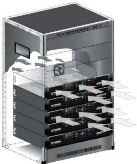
When using an equipment rack, mount units directly on top of each other. Close any open spaces in the rack with blank panels. (Open spaces will reduce cooling efficiency.) DO NOT block front or rear air vents.
The rack should be a minimum of 2 inches (5.1 cm) away from the amplifier, and the back of the rack should be a minimum of 4 inches (10.2 cm) from the amplifier back panel.
Air flow is front to back as illustrated in Figure 1.
natural_image
3D illustration of a server rack with internal components and ventilation ducts (no text or symbols)Figure 1: Proper rack venting
Front Panel Overview
text_image
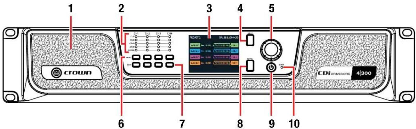
1 2 3 4 5 PRESETA CP: 192.06-0.00 AMP-1 AMP-2 AMP-3 AMP-4 AMP-5 AMP-6 AMP-7 AMP-8 AMP-9 AMP-10 AMP-11 AMP-12 AMP-13 AMP-14 AMP-15 AMP-16 AMP-17 AMP-18 AMP-19 AMP-20 AMP-21 AMP-22 AMP-23 AMP-24 AMP-25 AMP-26 AMP-27 AMP-28 AMP-29 AMP-30 AMP-31 AMP-32 AMP-33 AMP-34 AMP-35 AMP-36 AMP-37 AMP-38 AMP-39 AMP-40 AMP-41 AMP-42 AMP-43 AMP-44 AMP-45 AMP-46 AMP-47 AMP-48 AMP-49 AMP-50 AMP-51 AMP-52 AMP-53 AMP-54 AMP-55 AMP-56 AMP-57 AMP-58 AMP-59 AMP-60 AMP-61 AMP-62 AMP-63 AMP-64 AMP-65 AMP-66 AMP-67 AMP-68 AMP-69 AMP-70 AMP-71 AMP-72 AMP-73 AMP-74 AMP-75 AMP-76 AMP-77 AMP-78 AMP-79 AMP-80 AMP-81 AMP-82 AMP-83 AMP-84 AMP-85 AMP-86 AMP-87 AMP-88 AMP-89 AMP-90 AMP-91 AMP-92 AMP-93 AMP-94 AMP-95 AMP-96 AMP-97 AMP-98 AMP-99 AMP-100Figure 2: 4|300 front panel shown
1. Cooling Vents/Air Filters
Provides cooling air flow. Do not block or cover these vents. Air filters are removable.
2. Signal Level LED Indicators
These LEDs indicate channel signal level as follows:
- Clip LED – Lights yellow if the input clips or red if the output clips. Note that an output clip will always take priority over an input clip.
- -10dB LED – Lights green when the output signal reaches a level that is 10dB below full scale output of the amp.
- -15dB LED – Lights green when the output signal reaches a level that is 15dB below full scale output of the amp.
- -20dB LED – Lights green when the output signal reaches a level that is 20dB below full scale output of the amp.
- Signal LED – Lights green when signal is sensed at the input. The threshold for lighting this LED is -40dBu.
NOTE: The full scale output of the amplifier may change depending on the Low Z/High Z setting, as well as the amplifier model. See "Configuring Outputs for Low Z/High Z Operation" on page 40 for more information.
3. LCD (Display)
This color LCD provides product information and visual feedback for operating the CDi DriveCore amplifier from the front panel.
4. Back Button
Press this button to navigate back one level when navigating menus.
5. Encoder
This encoder supports rotary and pushbutton operation. It is used to navigate the CDi DriveCore's menus and select on-screen options. It is also used to adjust individual channel or overall system volume.
6. Channel Select Buttons
Pressing one of these buttons will select the corresponding channel; turning the ENCODER will then control the volume of the selected channel.
Pressing and holding a CHANNEL SELECT button for 2 seconds from the Home screen will display a Channel Details screen for that channel. The Channel Details screen shows additional details for the selected channel, including configured input source, output mode, status, channel temperature, and channel volume. Note that channel volume can also be controlled from this screen by turning the Encoder.
7. Channel Mute Buttons
Pressing each of these buttons will mute/unmute the corresponding amplifier output channel. Note that when a channel is muted, the front panel SIGNAL LEDs will still light to indicate input signal level presence, the CLIP LEDs will still light to indicate input clipping, and the LCD will flash "Mute".
8. Menu Button
Pressing this button will enter the Main menu, where amplifier settings can be edited.
9. Power Button
Turns the amplifier power on or off. The Power button has an integrated power symbol that illuminates blue when the power is on and green when the power is off. To prevent the unit from accidentally being powered off, the Power button must be pressed and held for 2 seconds when powering off.
NOTE: The Power button is disabled when using the AUX port Sleep circuit. See "Using the AUX Port" on page 70 for more information.
10. Data LED
This LED will illuminate yellow when there is valid HiQnet data being transmitted to/from the amplifier.
NOTE: 4-channel model shown. Indications per channel pair are identical for 2-channel models.
Rear Panel Overview
text_image
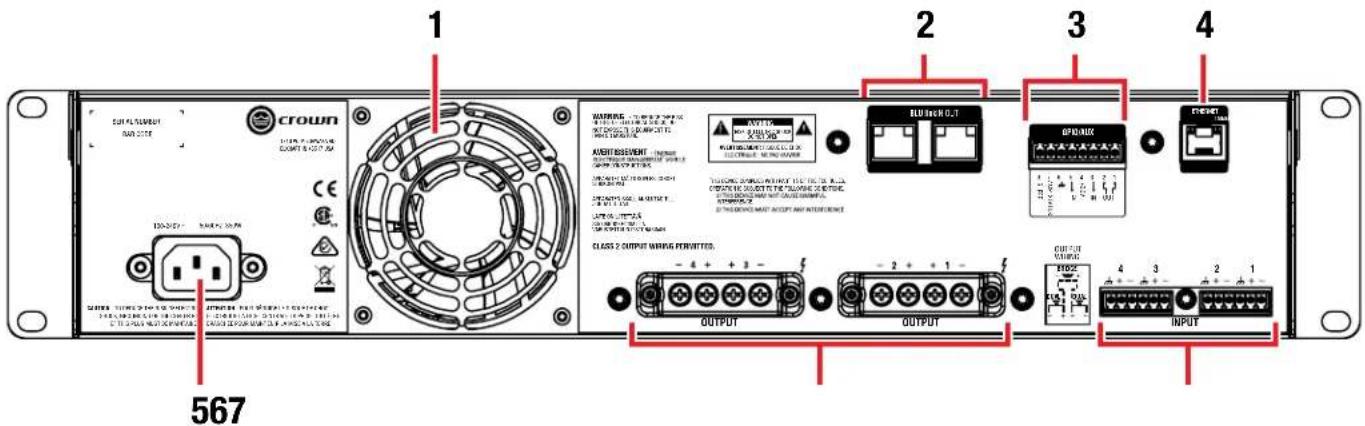
1 2 3 4 567 CROWN OUTPUT OUTPUT INPUTFigure 3: 4|300BL rear panel shown
1. Cooling Fan Outlet
Outlet for cooling air flow. Do not block or cover this outlet.
2. BLU link Input/Output Ports\*
These two RJ45 connectors are used for BLU link audio transport and are available only on the BLU link CDi DriveCore amplifier models. BLU link provides up to 256 channels of digital audio over Category 5e wiring. For information on the port LED indicators, see "BLU link Port LED Indicators" on page 60.
NOTE: BLU link audio will not pass through an Ethernet switch or router. BLU link connections must be made directly between BLU link devices.
3. General Purpose Input/Output (GPIO)
This 8-pin block connector combines the 2-in, 2-out GPIO with the SLEEP and AMP STATUS pins from the AUX circuit. See "Using the GPIO Control Port" on page 69 and "Using the AUX Port" on page 70 for further information on configuring and using these ports.
4. Ethernet (Network Control) Port\*
Connect this RJ45 port to a computer or network for monitoring and controlling the amplifier over Category 5e wiring via the Audio Architect software. The integrated LEDs in this Ethernet port will light as follows:
- Yellow LED
This LED lights when a network connection is established with the computer or network, and will flash to indicate network activity.
- Green LED
This LED indicates network speed and will light when connected to a 100 Mb network or not light when connected to a 10 Mb network.
NOTE: The Ethernet port is for network control only and will not transmit or receive BLU link audio.
5. AC Power Inlet
Connect the included AC power cord to this standard 15A, IEC type 320 inlet. Supported mains voltage range is 100-240V\~.
6. Output Terminal (Barrier Block) Connectors
One four-pole, touch-proof terminal strip per channel pair. Accepts up to 10 AWG wire or terminal forks. See "Wiring Output Connectors" on page 7 for information on wiring these connectors.
7. Audio Input (Terminal Block) Connectors
Connect your audio source outputs to these inputs using the provided plug-in connectors. One 6-pin plug-in connector can be used per input pair. These inputs are high impedance, balanced connections. See "Wiring Input Connectors" on page 7 for information on wiring these connectors.
*WARNING: Only connect to networks that remain inside the building.
Hardware Setup
Connecting the AC Power Cord
IMPORTANT: The amplifier output mode must be properly configured for the application before connecting the speakers and powering on the amplifier. By default, all outputs are configured for Low Z operation. See "Configuring the Amp" on page 11 for more information.
Connect your amplifier to the AC mains power outlet using the supplied AC power cord. First, connect the IEC end of the cord to the IEC connector on the amplifier. Then plug the other end of the cord to the AC mains.

WARNING: The third prong of the power connector (ground) is an important safety feature. Do not attempt to disable this ground connection by using an adapter or other methods.
Make certain the AC mains voltage and current ratings are sufficient to deliver full power to all amplifiers. CDi DriveCore Series amplifiers use a universal power supply. The AC voltage requirements are 100V-240V\~, 50/60Hz ( ± 10%). If the AC line voltage varies outside of this acceptable range, the amplifier's power supply will turn off and the blue Power LED will flash. The amplifier will turn back on when the AC line voltage returns to safe operating levels.
Power Up Procedure
When turning on the amplifier for the first time:
- Ensure all connections are disconnected with the exception of the power cord.
- Press the amplifier's POWER button. The Power indicator will light blue and the amplifier will boot as long as sufficient mains power is provided.
-
Once boot up is complete, turn the ENCODER counter-clockwise until all amp levels are set to -80dB in the front panel LCD.
-
Configure the amplifier as described in "Configuring the Amp" on page 11.
NOTE: The amplifier output mode must be properly configured for the application before connecting the speakers and powering on the amplifier. By default, all outputs are configured for Low Z operation.
-
Once the amplifier has been properly configured for the application, turn off the power — by pressing and holding the Power button for 2 seconds — then disconnect the power cord.
-
Turn down the level of your audio source.
-
Make all connections as described in "Wiring Input Connectors" and "Wiring Output Connectors" on page 7.
-
Once all connections have been made, reconnect the power cord and turn on the amplifier power.
-
Turn your audio source up to an optimum level. Refer to all device meters and ensure that at no point in the signal chain is the signal being clipped in any way. If any of the amplifier's Clip indicators light yellow, reduce the source level until the Clip LEDs no longer light.
-
Turn the amplifier's ENCODER clockwise until the desired loudness or power level is achieved, while making sure the amplifier's clip LEDs do not light.
IMPORTANT: Always turn off the amplifier — by pressing and holding the Power button for 2 seconds — and disconnect the power cord before making any wiring or installation changes.
IMPORTANT: When powering a fully configured PA system, always turn the amplifiers on last and off first.
For help with determining your system's optimum gain structure (signal levels) please refer to the Crown Amplifier Application Guide, available online at www.crownaudio.com.
Precautions
Your amplifier is protected from internal and external faults, but you should still take the following precautions for optimum performance and safety:
-
Configure the amplifier for proper operation, including input and output wiring hookup. Improper wiring can result in serious operating difficulties. For information on wiring and configuration, please consult "Wiring Input Connectors" and "Wiring Output Connectors" on page 7. For advanced setup techniques, consult Crown's Amplifier Application Guide available online at www.crownaudio.com.
-
Use care when making connections, selecting signal sources, and controlling the output level. The load you save may be your own!
-
Do not short the ground lead of an output cable to the input signal ground. This may form a ground loop and cause oscillations.
-
Never connect the output to a power supply, battery, or power main. Electrical shock may result.
-
Tampering with the circuitry or making unauthorized circuit changes may be hazardous and invalidate all agency listings.
-
Do not operate the amplifier with the Clip LEDs constantly flashing.
-
Do not overdrive the mixer, which will cause clipped signal to be sent to the amplifier. Such signals will be reproduced with extreme accuracy, and loudspeaker damage may result.
-
Do not operate the amplifier with less than the rated load impedance. Due to the amplifier's output protection, such a configuration may result in premature clipping and speaker damage.
REMEMBER: Crown is not liable for damage that results from overdriving other system components.
Wiring Input Connectors
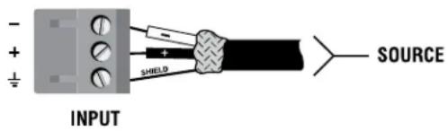
Crown recommends using pre-built or professionally wired balanced cables (two-conductor plus shield). Balanced wiring provides better rejection of unwanted noise and hum, however, unbalanced line may also be used.
Use 6-pin plug-in cable ends at the amp input connectors. A male connector is supplied for each input of your model of amplifier. Additional connectors are available from Crown (P/N 5024623).
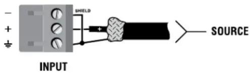
Figure 4 shows connector pin assignments for balanced wiring and Figure 5 shows connector pin assignments for unbalanced wiring. Note that for bridge mono operation, only the odd-numbered input channels (1,3) should be wired for each bridged pair.
text_image
INPUT SHEILD SOURCEFigure 4: Balanced wiring
text_image
- + + - SHIELD + SOURCE INPUTFigure 5: Unbalanced wiring
Wiring Output Connectors
IMPORTANT: The amplifier output mode (Low Z, 70V, 100V) must be properly configured for the application before connecting the speakers. By default, all outputs are configured for Low Z operation. See "Configuring the Amp" on page 11 for more information.
Before making any output connections, ensure the power cord is disconnected from the amplifier and carefully review the total impedance for loudspeakers connected to each amplifier output. If multiple loudspeakers are connected to an output in Low Z mode (i.e., in series, parallel, or series-parallel), be certain the total system impedance is within allowed specification for the output. When multiple loudspeakers are connected to one output in High Z mode, be certain total tapped power is below the rated power output for the channel. See "Specifications" on page 78 for supported load specifications.
NOTE: The Crown-designed output cover does not need to be removed to connect the output wiring.
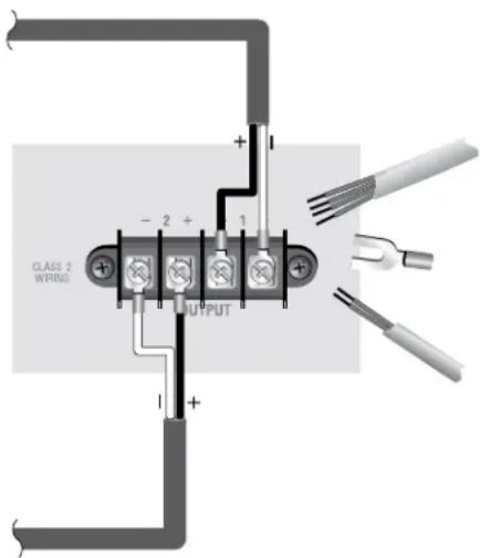
Crown recommends using the included terminal fork connectors and two-conductor or four-conductor, heavy gauge speaker wire. You may use terminal forks up to 10 AWG or bare wire for your output connectors (see Figure 6). For best results, Crown recommends Panduit part #PV10-6LF-L or equivalent terminal fork. For bare wire, it is highly recommended that output wiring is tinned. To reduce strain on input and output wiring, Crown recommends the use of horizontal lacer bars. For best results, Crown recommends Middle Atlantic® part# LBP-4R90 or equivalent horizontal lacer bar.
For low-impedance loads, refer to the table below and select the appropriate size of wire based on the distance from amplifier to speaker.
| Distance Wire Size | |
| Up to 25 ft. (7.6m) 16 AWG | |
| 26-40 ft. (7.9-12.2m) 14 AWG | |
| 41-60 ft. (12.5-18.3m) 12 AWG | |
| >60 ft (18.3m) 10 AWG |
text_image
CLASS 2 WIRING - 2 + 1 OUTPUTFigure 6: Wiring output connectors

CAUTION: Never use shielded cable for output wiring.

CAUTION: Never connect the speaker return to the chassis of the amplifier, or damage to the amplifier may result.

NOTE: Custom wiring should only be performed by qualified personnel. Class 2 output wiring is required.
For application-specific output connection diagrams, including how to wire outputs for bridge mono operation, see "Application Examples" on page 55.
Front Panel Menus & Navigation Overview
Menu Structure
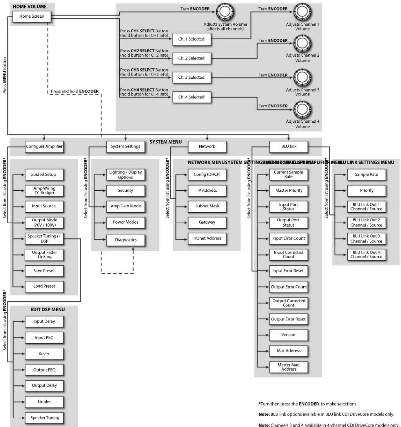
The below diagram shows the CDi DriveCore's front panel menu structure, as well as how to navigate and control channel volume.
flowchart
graph TD
    A["HOME VOLUME"] --> B["Home Screen"]
    B --> C["Press MENU Button"]
    C --> D["Press and hold ENCODER"]
    D --> E["Turn ENCODER"]
    E --> F["Adjusts Channel 1 Volume"]
    E --> G["Adjusts Channel 2 Volume"]
    E --> H["Adjusts Channel 3 Volume"]
    E --> I["Adjusts Channel 4 Volume"]
    J["Configure Amplifier"] --> K["System Settings"]
    K --> L["System MENU"]
    L --> M["Network"]
    M --> N["BLU link"]
    N --> O["Select from list using ENCODER*"]
    O --> P["Edit DSP MENU"]
    P --> Q["Input Delay"]
    P --> R["Input PEQ"]
    P --> S["Xover"]
    P --> T["Output PEQ"]
    P --> U["Output Delay"]
    P --> V["Limiter"]
    P --> W["Speaker Tuning"]

    K --> X["Select from list using ENCODER*"]
    X --> Y["Guided Setup"]
    X --> Z["Amp Wiring (Y, Bridge)"]
    X --> AA["Input Source"]
    X --> AB["Output Mode (70V / 100V)"]
    X --> AC["Speaker Tunings / DSP"]
    X --> AD["Output Fader Linking"]
    X --> AE["Save Preset"]
    X --> AF["Load Preset"]

    K --> AG["Select from list using ENCODER*"]
    AG --> AH["Lighting / Display Options"]
    AG --> AI["Security"]
    AG --> AJ["Amp Gain Mode"]
    AG --> AK["Power Modes"]
    AG --> AL["Diagnostics"]

    K --> AM["Network"]
    AM --> AN["Config (DHCP)"]
    AM --> AO["IP Address"]
    AM --> AP["Subnet Mask"]
    AM --> AQ["Gateway"]
    AM --> AR["HiQnet Address"]

    N --> AS["Select from list using ENCODER*"]
    AS --> AT["Current Sample Rate"]
    AS --> AU["Master Priority"]
    AS --> AV["Input Port Status"]
    AS --> AW["Output Port Status"]
    AS --> AX["Input Error Count"]
    AS --> AY["Input Corrected Count"]
    AS --> AZ["Input Error Reset"]
    AS --> BA["Output Error Count"]
    AS --> BB["Output Corrected Count"]
    AS --> BC["Output Error Reset"]
    AS --> BD["Version"]
    AS --> BE["Mac Address"]
    AS --> BF["Master Mac Address"]

    N --> BG["Select from list using ENCODER*"]
    BG --> BH["Sample Rate"]
    BG --> BI["Priority"]
    BG --> BJ["BLU Link Out 1 Channel / Source"]
    BG --> BK["BLU Link Out 2 Channel / Source"]
    BG --> BL["BLU Link Out 3 Channel / Source"]
    BG --> BM["BLU Link Out 4 Channel / Source"]

    style A fill:#f9f,stroke:#333
    style B fill:#ccf,stroke:#333
    style K fill:#cfc,stroke:#333
    style L fill:#fcc,stroke:#333
Figure 7: Menu structure diagram
The Home Screen
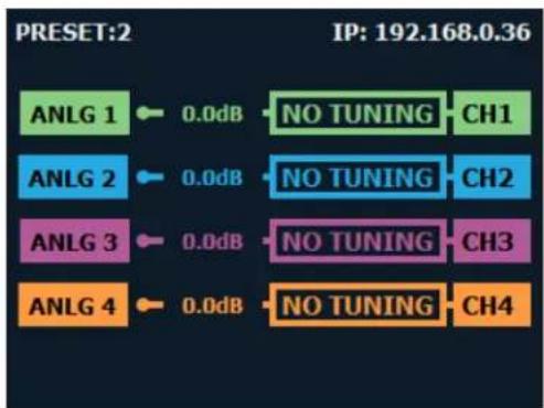
The Home screen (shown in Figure 8) is the first screen displayed in the CDi DriveCore's front panel display once the amplifier has completed the boot sequence.
From the Home screen, the ENCODER can be turned to adjust system volume or pressed and held to access the Diagnostics screen, the CHANNEL SELECT buttons can be pressed (or held) to adjust individual channel volume using the ENCODER, or the MENU button can be pressed to enter the Main menu to configure and view information about the amplifier.
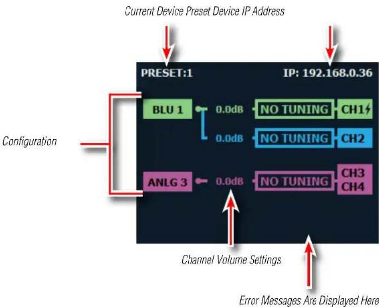
The Home screen shows at-a-glance amplifier configuration information, as shown in Figure 9. Here you can see the currently loaded device preset, device IP address, CDi DriveCore configuration, channel volume settings, and more.
NOTE: Throughout sections of this manual, some illustrations and text will refer to channel pair 1-2 only. Note that connections and settings for channels 3-4 (available on 4-channel CDi DriveCore models) are identical. Each channel can be configured independently in all models.
text_image
PRESET:2 IP: 192.168.0.36 ANLG 1 0.0dB NO TUNING CH1 ANLG 2 0.0dB NO TUNING CH2 ANLG 3 0.0dB NO TUNING CH3 ANLG 4 0.0dB NO TUNING CH4Figure 8: Home screen
flowchart
graph TD
    A["Current Device Preset Device IP Address"] --> B["Configuration"]
    B --> C["BLU 1"]
    C --> D["0.0dB"]
    D --> E["NO TUNING"]
    E --> F["CH1"]
    D --> G["0.0dB"]
    G --> H["NO TUNING"]
    H --> I["CH2"]
    B --> J["ANLG 3"]
    J --> K["0.0dB"]
    K --> L["NO TUNING"]
    L --> M["CH3"]
    L --> N["CH4"]
    style A fill:#f9f,stroke:#333
    style B fill:#ccf,stroke:#333
    style C fill:#cfc,stroke:#333
    style D fill:#fcc,stroke:#333
    style E fill:#cff,stroke:#333
    style F fill:#ffc,stroke:#333
    style G fill:#ffc,stroke:#333
    style H fill:#ffc,stroke:#333
    style I fill:#ffc,stroke:#333
    style J fill:#cfc,stroke:#333
    style K fill:#cfc,stroke:#333
    style L fill:#cfc,stroke:#333
    style M fill:#cfc,stroke:#333
    style N fill:#cfc,stroke:#333
Figure 9: Home screen layout
Adjusting Channel Volume
Channel volume can either be controlled globally or independently per channel. The volume range is from -80dB to 0dB. For gain structure purposes, it is important to note that volume adjustment occurs at the end of the DSP signal chain and before output limiting.
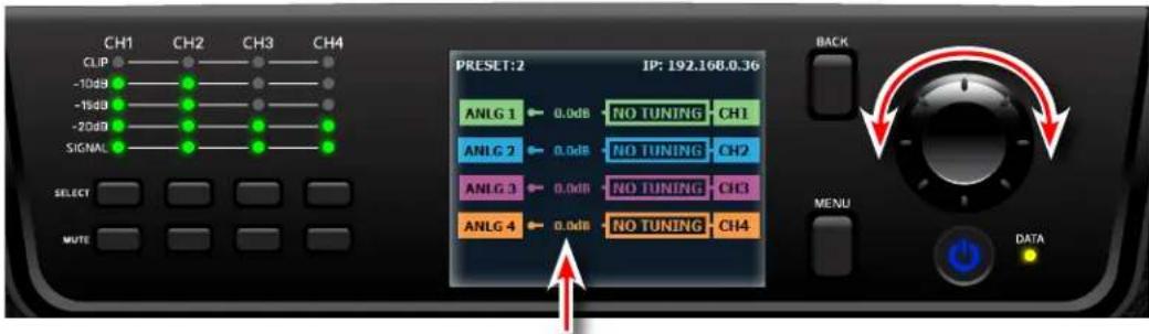
To adjust system (global) volume:
- From the Home screen, turn the ENCODER. The volumes for all channels will be adjusted respectively.
text_image
CH1 CH2 CH3 CH4 CLIP -10dB -15dB -20dB SIGNAL SELECT MUTE PRESET: 2 JP: 192.168.0.36 ANLG 1 0.0dB NO TUNING CH1 ANLG 2 0.0dB NO TUNING CH2 ANLG 3 0.0dB NO TUNING CH3 ANLG 4 0.0dB NO TUNING CH4 MENU DATA BACK DATANOTE: When adjusting system volume, all independent channel volume settings are adjusted relative to each other. This means that the minimum/maximum global volume limits are governed by the channel with the highest or lowest volume setting.
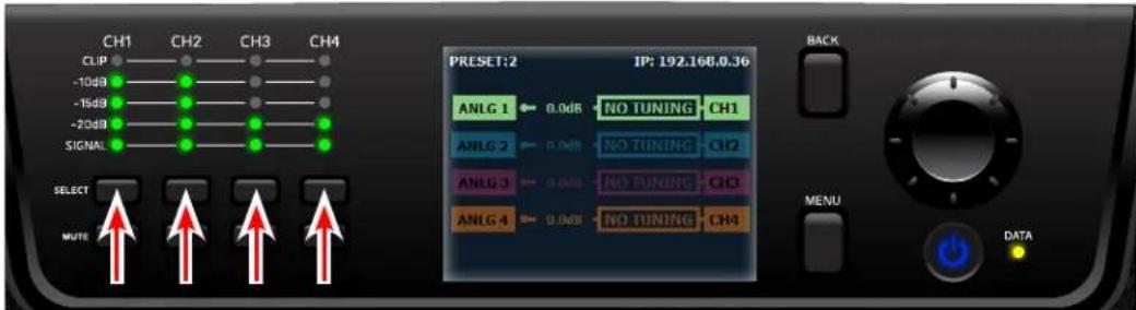
To adjust the volume of a particular channel:
- Select one of the channels using the corresponding SELECT button — the selected channel will now be highlighted in the display.
text_image
CH1 CH2 CH3 CH4 CLIP -10dB -15dB -20dB SIGNAL SELECT MUTE PRESET:2 IP: 192.166.9.36 ANLG 1 0.0dB NO TUNING CH1 ANLG 2 0.0dB NO TUNING CH2 ANLG 3 0.0dB NO TUNING CH3 ANLG 4 0.0dB NO TUNING CH4 MENU DATA BACK DATATIP: An alternative method for adjusting channel volume is to press and hold one of the channel SELECT buttons to bring up the Channel screen.
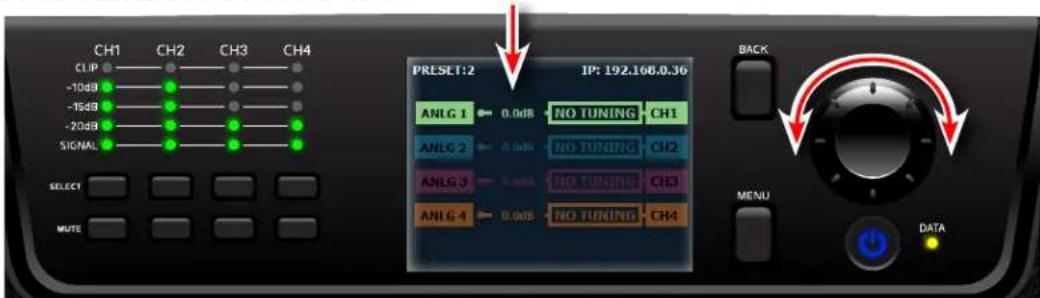
- Turn the ENCODER to adjust the selected channel's volume.
text_image
CH1 CH2 CH3 CH4 CLIP -10dB -15dB -20dB SIGNAL SELECT MUTE PRESET:2 IP: 192.168.0.36 ANLG 1 0.0dB NO TUNING CH1 ANLG 2 0.0dB NO TUNING CH2 ANLG 3 0.0dB NO TUNING CH3 ANLG 4 0.0dB NO TUNING CH4 BACK MENU DATA- When done, press the BACK button to deselect the channel.
Configuring the Amp
This section of the manual describes how to configure the CDi DriveCore amplifier for your application using the front panel user interface. This includes assigning input channels, editing internal routing and DSP settings, and configuring output mode settings. CDi DriveCore Series amplifiers can be configured using the built-in Guided Setup or manually using the individual menu options in the Configure Amplifier menu. Configuration can also be performed from a PC using HiQnet Audio Architect. For information on configuring the CDi DriveCore amplifiers using Audio Architect, see "Installing Audio Architect & Configuring the Network" on page 23
About Input & Output Configuration
The CDi DriveCore amplifiers ship from the factory with each output channel sourced from its respective analog input (e.g., analog input 1 goes to output 1, etc.), as shown in
Figure 10.
When viewing the Home screen, signal flow is represented by lines that traverse from the input source (leftmost box) to the channel output (rightmost box).
Additional amplifier configuration information can be seen at-a-glance on the Home screen, as shown in Figure 11.
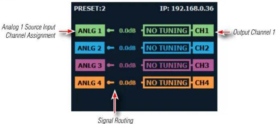
flowchart
graph LR
    A["Analog 1 Source Input Channel Assignment"] --> B["ANLG 1"]
    B --> C["0.0dB"]
    C --> D["NO TUNING"]
    D --> E["CH1"]
    F["Signal Routing"] --> G["ANLG 2"]
    G --> H["0.0dB"]
    H --> I["NO TUNING"]
    I --> J["CH2"]
    K["Signal Routing"] --> L["ANLG 3"]
    L --> M["0.0dB"]
    M --> N["NO TUNING"]
    N --> O["CH3"]
    P["Signal Routing"] --> Q["ANLG 4"]
    Q --> R["0.0dB"]
    R --> S["NO TUNING"]
    S --> T["CH4"]
    U["Input: IP: 192.168.0.36"] --> V["Output Channel 1"]
Figure 10: Default CDi DriveCore configuration
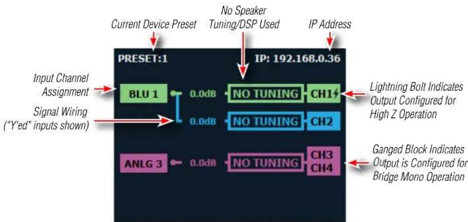
flowchart
graph TD
    A["Input Channel Assignment"] --> B["BLU 1"]
    C["Signal Wiring ("Y'ed" inputs shown)"] --> D["0.0dB"]
    B --> E["NO TUNING"]
    D --> F["0.0dB"]
    E --> G["CH1"]
    F --> H["CH2"]
    I["Current Device Preset"] --> J["No Speaker Tuning/DSP Used"]
    K["IP Address"] --> L["IP: 192.168.0.36"]
    M["Lightning Bolt Indicates Output Configured for High Z Operation"] --> N["Ch1"]
    O["Ganged Block Indicates Output is Configured for Bridge Mono Operation"] --> P["CH3 CH4"]
    Q["ANLG 3"] --> R["0.0dB"]
Figure 11: CDi DriveCore configuration example viewed from the front panel Home screen
Using the Guided Setup
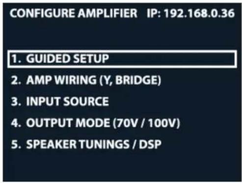
The Guided Setup walks you through all the steps to configure the amplifier. This includes assigning input channels, configuring internal DSP wiring and settings, and configuring output operation.
To configure the amplifier using the Guided Setup:
- From the Home screen, press the MENU button.
- Select the "Configure Amplifier" option from the menu using the ENCODER
- Select the "Guided Setup" option from the menu.
- Follow the on-screen steps, making selections with the ENCODER. If you wish to exit the Guided Setup at any time, press the MENU button.
text_image
CONFIGURE AMPLIFIER IP: 192.168.0.36 1. GUIDED SETUP 2. AMP WIRING (Y, BRIDGE) 3. INPUT SOURCE 4. OUTPUT MODE (70V / 100V) 5. SPEAKER TUNINGS / DSPFigure 12: Configure Amplifier menu
NOTE: After completing the Guided Setup, configuration settings will be retained after power cycling the amp. However, it's a good idea to save the configuration. The configuration must be saved before loading another device preset or the settings will be lost. See "Saving Device Presets" on page 63 for information on saving device presets.
Configuring Amp Wiring & Bridge Mode
From the Amp Wiring Setup screen (see Figure 13), input wiring can be configured. Here you can configure an input to feed multiple outputs (referred to as "Y'ing" the signal).
Bridge mono operation can also be configured from this screen. Bridging a pair of amplifier outputs will increase the power and voltage available at the output.
To configure input wiring and/or bridge mode manually:
- From the Home screen, press the MENU button.
- Select the "Configure Amplifier" option from the menu using the ENCODER
- Select the "Amp Wiring" option from the menu.
- Select the desired options for your application, making selections with the ENCODER.
- When done, select "Done" at the bottom of the screen.
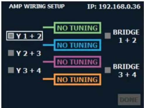
flowchart
graph TD
    A["BRIDGE 1 + 2"] --> B["NO TUNING"]
    C["Y 1 + 2"] --> D["NO TUNING"]
    E["Y 2 + 3"] --> F["NO TUNING"]
    G["Y 3 + 4"] --> H["NO TUNING"]
    I["DONE"] --> J["BRIDGE 3 + 4"]
Figure 13: Amp Wiring Setup screen
Available input options:
• Y 1+2
- Y 2+3*
• Y 3+4*
Available output options:
- Bridge 1+2
- Bridge 3+4*
For information on configuring signal routing and bridge mode settings in Audio Architect, see "Configuring Amp Wiring & Output Modes in Audio Architect" on page 39.
*Channel 3 and 4 options available in 4-channel CDi DriveCore models only.
Assigning Input Sources
Input sources can be assigned from the Input Source screen (see Figure 14). The default preset (Preset 1) is configured with all analog inputs feeding their respective output channels.
To assign input sources manually:
- From the Home screen, press the MENU button.
- Select the "Configure Amplifier" option from the menu using the ENCODER.
- Select the "Input Source" option.
- Use the ENCODER to select each input channel block and edit the input channel source assignment.
TIP: When assigning a BLU link input channel, the "BLU" option must first be selected from the list, then the ENCODER must be pressed. Turning the ENCODER will then select the desired BLU link channel from the list.
- When done, select "Done" at the bottom of the screen.
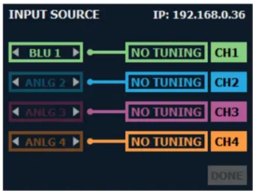
text_image
INPUT SOURCE IP: 192.168.0.36 BLU 1 ▶ NO TUNING CH1 ANLG 2 ▶ NO TUNING CH2 ANLG 3 ▶ NO TUNING CH3 ANLG 4 ▶ NO TUNING CH4 DONEFigure 14: Input Source screen
Available options:
- Analog 1
- Analog 2
• Analog 1+2 (mono summed) - Analog 3*
- Analog 4*
• Analog 3+4* (mono summed) - Any available BLU link channel**
- None
For information on assigning input sources in Audio Architect, see "Assigning Input Sources in Audio Architect" on page 36.
*Channel 3 and 4 options available in 4-channel CDi DriveCore models only.
**BLU link options available in BLU link CDi DriveCore models only. BLU link channels 129-256 not available when using a BLU link bus operating at a 96kHz sample rate.
Configuring Output Modes
From the Output Mode Setup screen (see Figure 15), outputs can be configured for Low Z or High Z operation. By default, the CDi DriveCore amplifiers are configured for Low Z (2/4/8Ω) operation on all outputs.
To configure output mode settings manually:
- From the Home screen, press the MENU button.
- Select the "Configure Amplifier" option from the menu using the ENCODER.
- Select the "Output Mode (70V/100V)" option from the menu.
- Use the ENCODER to navigate, make selections, and edit settings.
- When done, select "Done" at the bottom of the screen.
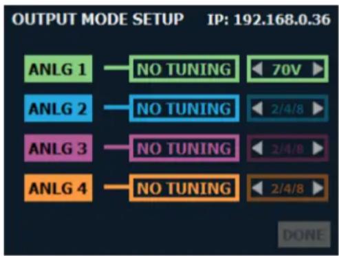
text_image
OUTPUT MODE SETUP IP: 192.168.0.36 ANLG 1 NO TUNING 70V ANLG 2 NO TUNING 2/4/8 ANLG 3 NO TUNING 2/4/8 ANLG 4 NO TUNING 2/4/8 DONEFigure 15: Output Mode Setup screen
Available options:
• 2/4/8 (LoZ), 70V, 100V
Configures the output for the application type. Select the "2/4/8" option for conventional low-impedance (2/4/8Ω) passive speakers, or choose the appropriate voltage setting if configuring the output for a high-impedance (constant-voltage) install application.
NOTE: If a pair of outputs are configured for bridge mono operation, selecting the 70V option will provide 140V and selecting the 100V option will provide 200V.
For additional information on output modes and configuring output mode settings in Audio Architect, see "Configuring Amp Wiring & Output Modes in Audio Architect" on page 39.
Configuring DSP
From the Speaker Tunings/DSP menu (see Figure 16) crossover, delay, and limiter settings can be adjusted to optimize the loudspeakers. Speaker tunings can also be selected for certain JBL models to easily optimize DSP settings for a particular loudspeaker model. Note that this screen shows the status of each DSP module (block). When a module is darkened, it is bypassed. When a module is bright, it is enabled.
To edit speaker tuning/DSP settings manually:
- From the Home screen, press the MENU button.
- Select the "Configure Amplifier" option from the menu using the ENCODER.
- Select the "Speaker Tunings/DSP" option from the menu.
- Use the ENCODER to select the module you wish to edit.
- Use the ENCODER to navigate, make selections, and edit settings.
- When done, select "Done" at the bottom of the screen.
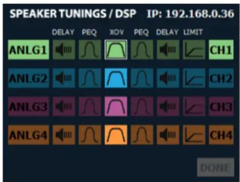
text_image
SPEAKER TUNINGS / DSP IP: 192.168.0.36 DELAY PEQ XOV PEQ DELAY LIMIT ANLG1 CH1 ANLG2 CH2 ANLG3 CH3 ANLG4 CH4 DONEFigure 16: Speaker Tunings/DSP screen
Delay
The CDi DriveCore amplifiers have an Input Delay (pre-crossover) and Output Delay (post-crossover) DSP module for each channel. Each is selectable when navigating the Speaker Tunings/DSP screen (see Figure 16). Once an Input or Output Delay module has been selected, delay settings can be edited from the Delay screen (see Figure 17).
The Output Delay can be used to time-align the various drivers in a multi-way speaker system or for close-proximity zone delay (to compensate for the slap-delay artifacts caused when bleed from an adjacent zone is audible). A total of up to 100ms of delay time is available in each Output Delay. The Input Delay can be used for delaying the system to the stage backline, delay fills, zone delay, or whenever more delay time is required than the Output Delay has to offer. The Input Delays provide an additional 1 second of delay time for each channel. Delay can be adjusted in milliseconds, feet, or meters.
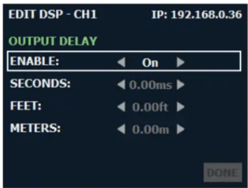
text_image
EDIT DSP - CH1 IP: 192.168.0.36 OUTPUT DELAY ENABLE: On SECONDS: 0.00ms FEET: 0.00ft METERS: 0.00m DONEFigure 17: Delay screen
To edit delay settings manually:
- From the Home screen, press the MENU button.
- Select the "Configure Amplifier" option from the menu using the ENCODER.
- Select the "Speaker Tunings/DSP" option from the menu.
- Select the "Input Delay" or "Output Delay" icon for the channel you wish to edit.
- Use the ENCODER to navigate, make selections, and edit settings.
- When done, select "Done" at the bottom of the screen.
Available options/parameters:
- Enable (Off, On)
Turns the Delay on or off. - Seconds (Input Delay: 0 – 1sec, Output Delay: 0 – 100ms)
Adjusts the delay time in milliseconds. - Feet (Input Delay: 0 – 1127ft, Output Delay: 0 – 112.7ft)
Adjusts the delay time in feet. - Meters (Input Delay: 0 – 343m, Output Delay: 0 – 34.3m)
Adjusts the delay time in meters.
For information on editing these settings in Audio Architect, see "Input/Output Delay Panels" on page 44.
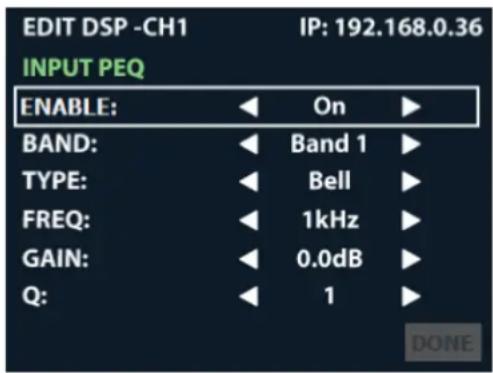
PEQ (Parametric EQ)
PEQ settings can be edited from the PEQ screen (see Figure 18). Input and Output PEQs are available. The Output (post-crossover) PEQs are typically used for speaker tuning settings, and the Input (pre-crossover) PEQs provide additional EQ filtering for the system if required.
To edit PEQ settings manually:
- From the Home screen, press the MENU button.
- Select the "Configure Amplifier" option from the menu using the ENCODER.
- Select the "Speaker Tunings/DSP" option from the menu.
- Select the pre or post-crossover "PEQ" icon for the channel you wish to edit.
- Use the ENCODER to navigate, make selections, and edit settings.
- When done, select "Done" at the bottom of the screen.
text_image
EDIT DSP -CH1 IP: 192.168.0.36 INPUT PEQ ENABLE: On BAND: Band 1 TYPE: Bell FREQ: 1kHz GAIN: 0.0dB Q: 1 DONEFigure 18: PEQ screen
Available options/parameters:
- Enable (Off, On)
Turns the PEQ on or off. - Band (Band 1 – Band 8)
Selects the filter band for editing. - Type
Selects the type of filter for the band. See available filter types listed below.
• Frequency (20Hz – 22kHz)
Sets the center/corner frequency of the band. - Gain (±20dB)
Sets the amount of gain (boost/cut) applied to the band. - Slope (3 - 15 dB/Oct)
- Width (0.10 - 32)
Sets the slope rate of the band for Shelf-type filters (only visible when a Shelf filter is selected).
Sets the width of the band for Bell-type filters, or adjusts the resonant peak for 2nd Order Lowpass/Highpass filters (only visible when one of the aforementioned filter types is selected).
Available filter types:
• Bell
- Low Shelf
- High Shelf
• LP BW1 (Butterworth 6dB/oct lowpass filter)
• HP BW1 (Butterworth 6dB/oct highpass filter)
- LP 2nd Order (6-12dB/oct lowpass filter with variable resonant peak using the Width parameter)
- HP 2nd Order (6-12dB/oct highpass filter with variable resonant peak using the Width parameter)
- Allpass 1 (90° phase shift)
- Allpass 2 (180° phase shift)
See "Input/Output EQ Panels" on page 43 for information on editing the PEQs in Audio Architect.
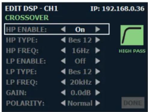
Crossover
Crossover filter settings can be edited from the Crossover screen (see Figure 19). Crossover filters are used to restrict the range of frequencies sent to a loudspeaker or driver for protection and sound optimization.
To edit crossover settings manually:
- From the Home screen, press the MENU button.
- Select the "Configure Amplifier" option from the menu using the ENCODER.
- Select the "Speaker Tunings/DSP" option from the menu.
- Select the "XOVER" icon for the channel you wish to edit.
- Use the ENCODER to navigate, make selections, and edit settings.
- When done, select "Done" at the bottom of the screen.
text_image
EDIT DSP - CH1 IP: 192.168.0.36 CROSSOVER HP ENABLE: On HP TYPE: Bes 12 HP FREQ: 16Hz LP ENABLE: Off LP TYPE: Bes 12 LP FREQ: 20kHz GAIN: 0.0dB POLARITY: Normal HIGH PASS DONEFigure 19: Crossover screen
Available options/parameters:
- HP Enable (Off, On)
Enables or disables the high-pass filter. - HP Type (Bessel 12 – 48dB/octave, Butterworth 6 – 48dB/octave, Linkwitz-Riley 12 – 48dB/octave) Selects the high-pass filter's type and slope rate in dB/octave.
• HP Freq (16Hz - 20kHz)
Sets the high-pass filter's corner frequency. - LP Enable (Off, On)
Enables or disables the low-pass filter. - LP Type (Bessel 12 – 48dB/octave, Butterworth 6 – 48dB/octave, Linkwitz-Riley 12 – 48dB/octave) Selects the low-pass filter's type and slope rate in dB/octave.
• LP Freq (16Hz - 20kHz)
Sets the low-pass filter's corner frequency. - Gain (-60 to 24dB)
Adjusts the crossover output gain, pre limiter. - Polarity (Normal, Inverted)
Selects between normal or inverted polarity for the selected output.
See "Crossover Panel" on page 42 for information on editing the Crossover in Audio Architect.
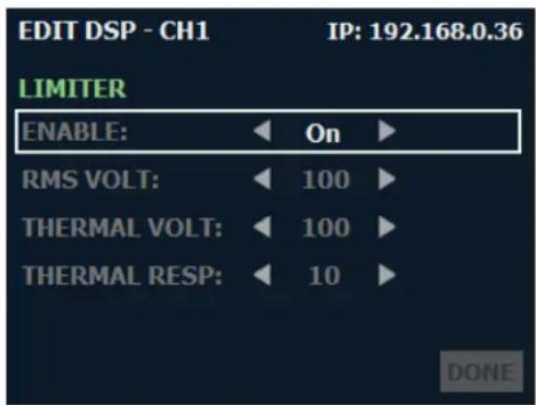
Limiter
The CDi DriveCore Series amplifiers include the LevelMAX™ suite of limiters. Limiter settings can be edited from the Limiter screen (see Figure 20). Limiters are used to set a "ceiling" on the output level to protect drivers from over-excursion. The thermal limiters in the CDi DriveCore Series amplifiers can also protect against thermal driver failure (overheating).
To edit limiter settings manually:
- From the Home screen, press the MENU button.
- Select the "Configure Amplifier" option from the menu using the ENCODER.
- Select the "Speaker Tunings/DSP" option from the menu.
- Select the "Limit" icon for the channel you wish to edit.
- Use the ENCODER to navigate, make selections, and edit settings.
- When done, select "Done" at the bottom of the screen.
text_image
EDIT DSP - CH1 IP: 192.168.0.36 LIMITER ENABLE: On RMS VOLT: 100 THERMAL VOLT: 100 THERMAL RESP: 10 DONEFigure 20: Limiter screen
Available options/parameters:
- Enable (Off, On)
Turns the Limiter on or off.
• RMS Voltage (1 – 400VRMS)
Sets the RMS voltage limit for the output.
• Thermal Voltage (1 - 500V)
Sets the long-term output power limit of the amplifier to what the loudspeaker load can handle without overheating and going into thermal compression. This is based on the AES power/voltage ratings of drivers outlined in the AES2-2012 standard.
• Thermal Response (1 – 600 sec)
Sets the time it takes for the thermal limiter to adjust output voltage. This is based on the AES power/voltage ratings of drivers outlined in the AES2-2012 standard.
NOTE: The LevelMax limiters include sidechain EQ for advanced speaker tunings. Sidechain EQ parameters are not user adjustable.
Additional limiter parameters are available in Audio Architect. For more information, see "LevelMAX Panel" on page 45.
For more information on the LevelMAX limiters and how to set the parameters, see the LevelMAX white paper available at www.crownaudio.com.
Configuring Speaker Tunings
Speaker tunings can be selected when navigating the Guided Setup or at the end of each channel from the Speaker Tunings/DSP screen (see Figure 21).
Speaker tunings apply DSP settings specific to a particular speaker, making it easy to optimize a speaker's performance.
To select a speaker tuning for a channel:
- From the Home screen, press the MENU button.
- Select the "Configure Amplifier" option from the menu using the ENCODER.
- Select the "Speaker Tunings/DSP" option from the menu.
-
Scroll to the end of the channel for which you are selecting a speaker tuning—a box will appear that reads "No Tuning".
-
Press the ENCODER. A list of available speaker tunings will appear on the screen.
-
Use the ENCODER to navigate the list then press the ENCODER to select the matching speaker series. Additional prompts will appear to allow selection of the specific speaker model and additional options depending on the tuning selected.
-
A confirmation prompt will appear that provides additional information on the tuning. Use the ENCODER to apply or cancel the selection.
-
Repeat for any additional channels.
-
When done, select "Done" at the bottom of the screen.
-
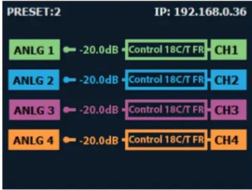
The screenshot below shows an example of how the Home screen will look after speaker tunings have been configured.
other
| Channel | Signal | Value (dB) | | :--- | :--- | :--- | | ANLG 1 | Control 18C/T FR | CH1 | | ANLG 2 | Control 18C/T FR | CH2 | | ANLG 3 | Control 18C/T FR | CH3 | | ANLG 4 | Control 18C/T FR | CH4 | PRESET:2 IP: 192.168.0.36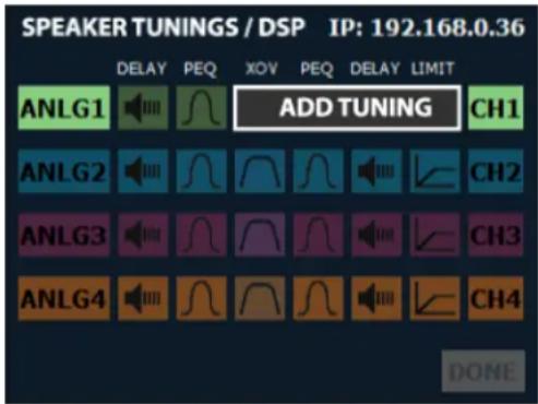
text_image
SPEAKER TUNINGS / DSP IP: 192.168.0.36 DELAY PEQ XOV PEQ DELAY LIMIT ANLG1 ADD TUNING CH1 ANLG2 CH2 ANLG3 CH3 ANLG4 CH4 DONEFigure 21: Selecting a speaker tuning
See "Configuring Speaker Tunings in Audio Architect" on page 41 for information about configuring speaker tunings in Audio Architect.
Configuring Output Fader Linking
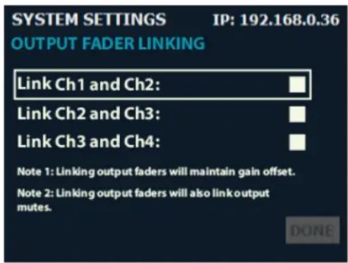
The Output Fader Linking screen (see Figure 22) allows the amplifier's output channel levels and mutes to be linked for ganged operation.
To edit the Output Fader Linking settings:
- From the Home screen, press the MENU button.
- Select the "System Settings" option from the menu using the ENCODER.
- Select the "Output Fader Linking" option from the menu, then press the ENCODER.
- Turn the ENCODER to select the desired option, then press the ENCODER to toggle whether the option is enabled (checked) or disabled (unchecked).
- When done, use the ENCODER to select "Done" at the bottom of the screen.
NOTE: The output level faders can also be linked using Audio Architect. See"Main CDi DriveCore Control Panel" on page 34 for more information.
text_image
SYSTEM SETTINGS IP: 192.168.0.36 OUTPUT FADER LINKING Link Ch1 and Ch2: Link Ch2 and Ch3: Link Ch3 and Ch4: Note 1: Linking output faders will maintain gain offset. Note 2: Linking output faders will also link output mutes. DONEFigure 22: Output Fader Linking screen
Available options:
- Link Ch1 and Ch2
Links channel 1 and channel 2 output level faders for ganged operation. - Link Ch2 and Ch3
Links channel 2 and channel 3 output level faders for ganged operation. This option is only available in 4-channel amp models. - Link Ch3 and Ch4
Links channel 3 and channel 4 output level faders for ganged operation. This option is only available in 4-channel amp models.
TIP: Checking multiple checkboxes allows adjacent channels to be linked. For example, checking the "Link Ch1 and Ch2" checkbox and the "Link Ch2 and Ch3" checkbox will link channels 1, 2, and 3 together. Checking all checkboxes will link all channels together.
Configuring BLU link Settings
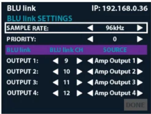
The BLU link Settings menu is only available in BLU link CDi DriveCore models. From the BLU link Settings menu (see Figure 23), BLU link sample rate, clock priority, and outputs can be configured.
To configure BLU link settings:
- From the Home screen, press the MENU button.
- Select the "BLU link" option from the menu using the ENCODER.
- Select the "BLU link Settings" option from the menu.
- Select the desired options for your application, making selections with the ENCODER.
- When done, select "Done" at the bottom of the screen.
text_image
BLU link IP: 192.168.0.36 BLU Link SETTINGS SAMPLE RATE: 96kHz ▶ PRIORITY: 0 ▶ BLU link BLU link CH SOURCE OUTPUT 1: 9 Amp Output 1 ▶ OUTPUT 2: 10 Amp Output 2 ▶ OUTPUT 3: 11 Amp Output 3 ▶ OUTPUT 4: 12 Amp Output 4 ▶ DONEFigure 23: BLU link Settings menu
Available options:
• Sample Rate (48kHz, 96kHz)
Sets the BLU link sample rate in the amplifier. Sample rate can be set to 48kHz (default) or 96kHz. When set to 48kHz, the amplifier can access BLU link channels 1-256. When set to 96kHz, the amplifier can access BLU link channels 1-128.
NOTE: The sample rate must be set to match all other devices on the BLU link bus in order to pass BLU link audio.
NOTE: The CDi DriveCore amplifiers process audio using a fixed 96kHz internal sampling rate. When using a BLU link sample rate of 48kHz, the audio signal from the BLU link bus will be sample rate converted from 48kHz up to 96kHz when entering the amp, and any audio signals sent from the amp back to the BLU link bus will be converted from 96kHz down to 48kHz.
NOTE: If the amp is configured to use any BLU link channels between 129-256 and the sample rate is then changed from 48kHz to 96kHz, all BLU link assignments above 128 will default back to an "unassigned" state since they will no longer be applicable at 96kHz.
- Priority (0-254)
Determines which device on the BLU link bus will provide audio clock for the entire bus. The higher the value, the higher the priority. Under certain conditions, such as when two devices have the same Priority settings, other factors may be used to determine BLU link clock priority (see "Mastership" on page 61 for more information).
- BLU link Channel Output 1-4\* (Off, 1-254 @ 48kHz / 1-128 @ 96kHz)
The CDi DriveCore amplifiers are capable of outputting up to 2 channels (2-channel models) or 4 channels (4-channel models) of audio onto the BLU link bus. These options allow you to assign the desired BLU link output channels. Channels 1-256 are available when using a 48kHz BLU link sample rate and channels 1-128 are available when using a 96kHz BLU link sample rate.
- BLU link Source Output 1-4\*
These options allow you to select the source to route to each BLU link output channel, with the following options available:
- Analog Input 1-4* (routes the pre-processed audio signal from the input)
- Amp Output 1-4* (routes the same audio signal present at the amplifier outputs)
For information on routing BLU link channels to the amplifier's inputs, see "Assigning Input Sources" on page 14.
For information on configuring BLU link output settings in Audio Architect, see "Configuring BLU link Outputs" on page 38.
*Channel 3 and 4 options available in 4-channel CDi DriveCore models only.
Installing Audio Architect & Configuring the Network
Introduction to HiQnet Audio Architect
CDi DriveCore amplifiers can be set up from either the front panel or from the HiQnet Audio Architect software program. Access to some settings and functionality are only available from Audio Architect.
The latest version of Audio Architect can be downloaded at www.audioarchitect.harmanpro.com/en-US/software. To communicate with Audio Architect, the amplifier must be connected to a TCP\IP network via the rear panel Ethernet port and, in some cases, configured for the network.
NOTE: The BLU link ports available on BLU link CDi DriveCore models cannot be used for network control and monitoring of the amplifier.
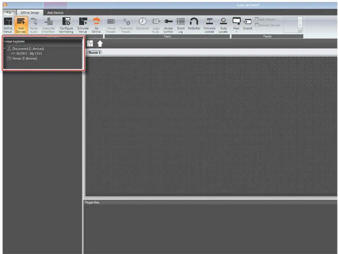
When Audio Architect is first loaded, the software will scan the network for HiQnet devices. All devices that are discovered on the network will be found under the Device Tree menu in the left-hand side of the Main Audio Architect window (see Figure 24).
text_image
Audio Architect* File Offline Design Add Devices Define Venue Add Devices Route Audio Associate Amplifiers Configure Monitoring Simulate Venue Go Online Venue Presets Parameter Presets Scheduler Logic Rules Access Control Event Log NetSetter Firmware Update Auto Locate New Import Add Devices Remove Devices Venue Explorer Discovered (1 devices) 0x2001 - My CDs Venue (0 devices) Tools Pands Room 1 PropertiesFigure 24: Device Tree menu
NOTE: If devices are not discovered and displayed in the Device Tree menu as shown above, the device and/or network may not be configured correctly. See "Configuring Amplifier Network Settings" on page 24 for information on configuring network settings.
Configuring Amplifier Network Settings
Network settings can be configured from either the CDi DriveCore's front panel or from the NetSetter software application. DHCP is enabled by default, allowing the CDi DriveCore amplifiers to automatically obtain an IP address when connecting to an Ethernet switch or router with an active DHCP server, or when using Auto-IP.
Configuring the Network from the Front Panel
To configure the amplifier's network settings from the front panel:
- From the Home screen, press the MENU button.
- Select the "Network" option from the menu using the ENCODER.
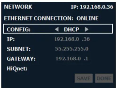
- Use the ENCODER to select and edit network settings.
- When done, select "Save" then "Done" at the bottom of the screen for the changes to take affect.
TIP: To quickly configure multiple HiQnet devices, connect all the devices and configuration computer to the same network and use the NetSetter software application (see "Configuring the Network using NetSetter" on page 25).
text_image
NETWORK IP: 192.168.0.36 ETHERNET CONNECTION: ONLINE CONFIG: DHCP IP: 192.168.0 .36 SUBNET: 55.255.255.0 GATEWAY: 192.168.0 .1 HiQnet: SAVE DONEFigure 25: Network screen
Available options/parameters:
- Config (DHCP, Static)
Turns DHCP on or off. Select "DHCP" to allow the amplifier to automatically obtain an IP address from a DHCP server or via Auto-IP. Select "Static" to manually configure the amplifier's network settings.
• IP
Allows for viewing and editing of the amplifier's IP address. - Subnet
Allows for viewing and editing of the amplifier's subnet mask. - Gateway
Allows for viewing and editing of the gateway address, if required to access the network. If using a router, the gateway address will typically be the router address.
• HiQnet
Allows for viewing and editing of the HiQnet node address. Each device on a HiQnet network must have a unique node address.
For additional information on network configuration, please visit www.audioarchitect.harmanpro.com.
Configuring the Network using NetSetter
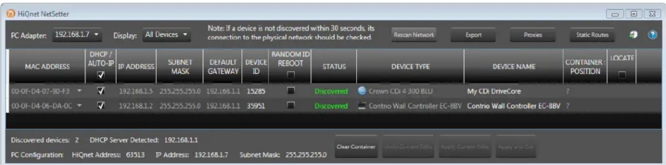
NetSetter is a software tool which enables you to discover HiQnet devices and reconfigure their network settings in real time, from one central location. Its function is to configure a system of devices to interoperate correctly on the same network and resolve conflicts quickly and easily. The latest version of NetSetter can be downloaded at www.audioarchitect.harmanpro.com/en-US/software.
The top of the NetSetter window displays overall operational functions that are available. At the bottom of the NetSetter window is an informational section that lists the number of discovered devices and the IP address of the DHCP server (if available). There is also information regarding the PC HiQnet Address, IP Address, and Subnet Mask.
text_image
HiQnet NetSetter PC Adapter: 192.168.1.7 Display: All Devices Note: If a device is not discovered within 30 seconds, its connection to the physical network should be checked. Rescan Network Export Proxies Static Routes ? MAC ADDRESS DHCP / AUTO-IP IP ADDRESS SUBNET MASK DEFAULT GATEWAY DEVICE ID RANDOM ID REBOOT STATUS DEVICE TYPE DEVICE NAME CONTAINER : LOCATE POSITION 00-0F-D4-07-90-F3 ✓ 192.168.1.5 255.255.255.0 192.168.1.1 15285 Discovered Crown CD4 4 300 BLU My CD4 DriveCore ? 00-0F-D4-06-DA-OC ✓ 192.168.1.2 255.255.255.0 192.168.1.1 35951 Discovered Contrio Wall Controller EC-8BV Contrio Wall Controller EC-8BV ? Discovered devices: 2 DHCP Server Detected: 192.168.1.1 PC Configuration: HiQnet Address: 63513 IP Address: 192.168.1.7 Subnet Mask: 255.255.255.0 Clear Container Undo Current Eds Apply Current Eds Apply and CutFigure 26: NetSetter window
1. PC Adapter
Use this dropdown menu to select the Network Interface Card (NIC) that NetSetter will use to attempt to discover HiQnet devices. All available NIC's are listed by IP Address. Selecting a new NIC will force a rescan of the network to which the new NIC is connected.
2. Display
The options available in this dropdown menu will filter the device list as follows:
a. All Devices
This is the default setting. All discovered devices are displayed.
b. HiQnet ID conflicts
Only discovered devices with HiQnet address conflicts are displayed.
c. IP address conflicts
Only discovered devices with IP address conflicts are displayed.
d. All conflicts
Only discovered devices with either HiQnet address conflicts or IP address conflicts are displayed.
e. Locked
Only devices in a Locked configuration will be displayed.
f. Discovering
Only devices in the process of being discovered will be displayed.
g. Discovered
Only discovered devices with no conflicts will be displayed.
h. DHCP/Auto-IP
All devices which have been discovered with DHCP/Auto-IP enabled and those which have been set to use DHCP/Auto-IP on applying the edits are displayed.
3. Rescan Network
Clicking this button re-scans the network to which the currently selected NIC is connected.
4. Export
Clicking this button brings up a "Save As" window, allowing you to save the HiQnet Addresses and IP Configurations of all devices on the network as a .CSV (Comma Separated Values) formatted file. This allows you to archive the information and open it in a spreadsheet program such as Microsoft® Excel®.
5. Proxies
This feature is used to connect to devices that cannot automatically be located by Audio Architect due to network configuration or security measures via proxy connections.
6. Static Routes
This feature is used to set up a static route and connect directly to a device located on a different subnet than the PC.
7. Clear Container
Resets the Container/Position Venue data of the selected device. The action occurs on either "Apply Current Edits" or "Apply and Exit" so that changes may be undone with the Undo Current Edits button.
8. Undo Current Edits
Resets any open edits in the grid to the values as currently on the network.
9. Apply Current Edits
Confirms any open edits in the grid. Devices update accordingly until connection is re-established with HiQnet NetSetter.
10. Apply and Exit
Confirms and saves any open edits in the grid. Devices update accordingly until connection is re-established with HiQnet.
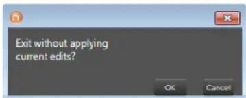
NOTE: If you have made changes to NetSetter and attempt to exit the program, the confirmation window shown in Figure 27 will appear. Clicking OK will apply the edits you have made since opening NetSetter. Clicking Cancel will return you to the program.
text_image
Exit without applying current edits? OK CancelFigure 27: Confirmation window
The NetSetter Grid
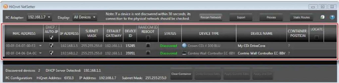
The NetSetter grid is divided into the 12 sections described below.
text_image
HiQnet NetSetter PC Adapter: 192.168.1.7 Display: All Devices Note: If a device is not discovered within 30 seconds, its connection to the physical network should be checked Rescan Network Export Proces Static Routes MAC ADDRESS DHCP / AUTO-IP ✓ IP ADDRESS SUBNET MASK DEFAULT GATEWAY DEVICE ID RANDOM ID REBOOT STATUS DEVICE TYPE DEVICE NAME CONTAINER POSITION LOCATE 00-0F-D4-07-90-F3 ✓ 192.168.1.5 255.255.255.0 192.168.1.1 15285 Discovered Crown CDi 4 300 BLU My CDi DriveCore ? 00-0F-D4-06-DA-OC ✓ 192.168.1.2 255.255.255.0 192.168.1.1 35951 Discovered Contrio Wall Controller EC-BBV Contrio Wall Controller EC-BBV ? Discovered devices: 2 DHCP Server Detected: 192.168.1.1 PC Configuration: HiQnet Address: G3513 IP Address: 192.168.1.7 Subnet Mask: 255.255.255.0 Clear Container Enable Command Setts Apply Command Setts Apply And ComFigure 28: NetSetter grid
1. MAC Address
Displays the MAC address of the discovered device. The data in this field cannot be edited.
NOTE: If more than one MAC address is discovered for a single device (e.g., HiQnet device MAC address, AVB card MAC address, etc.), the field will be represented as a dropdown menu and the desired MAC address can be selected from the list. For a device connected to the same control network with two control MAC addresses, the MAC address field will be displayed in red.
2. DHCP/Auto-IP
If the discovered device is configured to use DHCP/Auto-IP, this checkbox will be checked. If the discovered device is not using DHCP/Auto-IP, you may check the box so it will do so on applying edits. The device row will then become selected. The device will attempt to have its IP settings configured by DHCP on applying the edits; if no DHCP server is present, the device will attempt to have IP settings configured by Auto-IP.
All devices in the current filter view may be configured with DHCP/Auto-IP enabled by checking the checkbox in the column header — the individual checkboxes for all devices will become checked. If a single individual checkbox for a device is subsequently unchecked, the column header DHCP/Auto-IP checkbox will be automatically unchecked. Conversely, all devices in the current filter view can be configured with DHCP/Auto-IP disabled by unchecking the checkbox in the column header.
DHCP server status will be among the information displayed at the bottom of the NetSetter window. If a DHCP server is not detected, the information will read "DHCP server not detected". Note that checking a device's DHCP/Auto-IP checkbox has no immediate effect on the column sort order.
NOTE: Once edits have been made, it is critical to click the Apply Current Edits or Apply and Exit buttons for the changes to take affect.
3. IP Address
Displays the IP address of the discovered device. A valid IP address may be edited inline. If the edited value scopes the device out of the current Display filter, it will not be visible.
NOTE: A discovered device with an IP address that conflicts with that of another, already discovered device will be displayed in red. A conflicting IP address may be edited inline if you wish to change the device IP address on applying current edits. If DHCP/Auto-IP is enabled, the IP address field may not be edited inline.
NOTE: Once edits have been made, it is critical to click the Apply Current Edits or Apply and Exit buttons for the changes to take affect.
4. Subnet Mask
Displays the Subnet Mask of the discovered device. The Subnet Mask may be edited inline. The device row will be ordered accordingly with the current column sort immediately on successful editing of the field. The device row will remain selected.
NOTE: If DHCP/Auto-IP is enabled, the Subnet Mask field may not be edited inline.
NOTE: Once edits have been made, it is critical to click the Apply Current Edits or Apply and Exit buttons for the changes to take affect.
5. Default Gateway
Displays the Default Gateway of the discovered device. The Default Gateway may be edited inline. The device row will be ordered accordingly with the current column sort immediately on successful editing of the field. The device row will remain selected.
NOTE: If DHCP/Auto-IP is enabled, the Default Gateway field may not be edited inline.
If the device is being rediscovered, then the following behavior will occur:
- When the device is not selected, the device Default Gateway address field is displayed but is grayed out.
- When the device is selected and highlighted in orange, the field is represented in dark gray.
NOTE: Once edits have been made, it is critical to click the Apply Current Edits or Apply and Exit buttons for the changes to take affect.
6. Device ID
Displays the HiQnet address of the discovered device. This field may be edited inline if you want to change the device HiQnet address. If the edited value scopes the device out of the current Display filter, it will not be visible and no devices will be selected. If devices are discovered with a conflicting HiQnet address, then the following will occur:
- The HiQnet ID field of a discovered device will be displayed in pink when a HiQnet address conflicts with that of another, already discovered HiQnet address.
- When the device is selected and highlighted in orange, the field is represented in red.
- The HiQnet address is not displayed, instead a dash is displayed as grayed out.
NOTE: A conflicting HiQnet address may be edited inline if you want to change the device HiQnet address.
NOTE: Devices are not discoverable at the IP level. A device which is not discoverable at the IP level (invalid IP address, etc.) will not be able to report a HiQnet address. In this instance, the HiQnet ID field will display a "?" to indicate that the field may exist but that the software does not have enough discoverability of the device to determine the value. A blank field or "-" implies the value is null and the HiQnet ID field may not be edited inline.
NOTE: Once edits have been made, it is critical to click the Apply Current Edits or Apply and Exit buttons for the changes to take affect.
7. Random ID Reboot
When enabled, the device will be given a random HiQnet address. If you want to set the HiQnet address of a device to a random ID, check the Random ID checkbox. If the checkbox is unchecked before applying current edits, the prior HiQnet ID value will be restored.
All devices in the current filter view may be set to Random HiQnet ID by checking the checkbox in the column header — the individual checkboxes for all devices will become checked. If any individual checkbox is subsequently unchecked, the column header Random ID checkbox will automatically be unchecked. Conversely, if all devices in the current filter view are set to Random ID on and the Random HiQnet ID column header checkbox is checked, all devices may be set to Random ID off by unchecking the column header checkbox — the individual checkboxes for all devices will become unchecked.
NOTE: Devices are not discoverable at the IP level. A device which is not discoverable at the IP level (invalid IP address, etc.) will not be able to report a HiQnet address. In this instance, the Random ID checkbox will be unavailable.
8. Status
Displays the current discovery status of the device. The Status field may not be edited. Discovery status hierarchy is as follows:
a. Discovered
If a device has a unique IP address and a unique HiQnet address, this condition will be shown unless the device is access controlled. When the device is not selected, the "Discovered" label is represented in green.
The "Discovered" status is determined by the following conditions:
- The device is discoverable at the MAC address level.
- The device has a valid and unique IP address (manual or DHCP/Auto-IP).
- The device has a unique HiQnet address.
- The device is not access controlled.
b. IP Conflict
If a device has an IP address conflict, this error will be shown regardless of other status notifications. When the device is not selected, the "IP conflict" label is represented in blue.
The "IP conflict" status is determined by the following conditions:
- The device is discoverable at the MAC address level.
- The device has an IP address that conflicts with another device which has already been discovered by NetSetter.
c. HiQnet Conflict
If a device has a unique IP address yet has a HiQnet address conflict, this error will be shown regardless of other status notifications. When the device is not selected, the "HiQnet conflict" label is represented in red.
The "HiQnet conflict" status is determined by the following conditions:
- The device is discoverable at the MAC address level.
- The device has a valid and unique IP address (manual or DHCP/Auto-IP).
- The device has a HiQnet address that conflicts with another device which has already been discovered by NetSetter.
d. Locked
If a device has a unique IP address and a unique HiQnet address, this condition will be shown if the device is access controlled. When the device is not selected, the "Locked" label is represented in yellow.
The "Locked" status is determined by the following conditions:
- The device is discoverable at the MAC address level.
- The device has a valid and unique IP address (manual or DHCP/Auto-IP).
• The device has a unique HiQnet address.
• The device is access controlled.
When a device has been discovered in a Locked state and any field is attempted to be edited for the first time, a dialog prompting for the Admin password will appear. Only a successful login with the Admin password will enable all fields to be edited. This state may need to be reset on rediscovery after applying current edits, requiring the Admin password to be entered again.
e. Discovering
This condition will be displayed if the device has had changes made to its IP configuration or HiQnet address and HiQnet NetSetter is waiting to re-establish connection. When a device being rediscovered is not selected, all fields within the device row are displayed but grayed out.
The "Discovering" status is determined by the following conditions:
- The device had been previously discovered at the MAC address level.
- Edits had been made to one or more fields.
- The device is being rediscovered after applying current edits.
NOTE: Since the sort order automatically updates when a field within the sorted column is updated, the rediscovered device will occupy the same row on rediscovery. The exception is when DHCP/Auto-IP or Random ID has been set prior to applying current edits, in which case the rediscovered device will occupy the appropriate row in the current column sort order.
9. Device Type
The device class name is displayed here, as reported by the discovered device. To the left of each device class name, the brand icon is displayed. The software application name is displayed for discovered PCs running an instance of HiQnet software. HiQnet software programs include System Architect, Audio Architect, and Performance Manager.
NOTE: The Device Type field may not be edited inline.
NOTE: Devices are not discoverable at the IP or HiQnet level. A device which is not discoverable at the IP level (invalid IP address, etc.) or HiQnet address level (HiQnet address conflict, etc.) will not be able to report its class name. In this instance, the Device Type field will display a "?" to indicate that the field may exist but that the software does not have enough discoverability of the device to determine the value. A blank field or "-" implies the value is null.
10. Device Name
The user-definable Device Name is displayed here, as reported by the discovered device.
NOTE: This field may be edited inline if you want to change the Device Name. This field may not be edited for discovered PCs running an instance of HiQnet software.
NOTE: Devices are not discoverable at the IP or HiQnet level. A device which is not discoverable at the IP level (invalid IP address, etc.) or HiQnet address level (HiQnet address conflict, etc.) will not be able to report its Device Name. In this instance, the Device Name field will display a "?" to indicate that the field may exist but that the software does not have enough discoverability of the device to determine the value. A blank field or "-" implies the value is null.
NOTE: Once edits have been made, it is critical to click the Apply Current Edits or Apply and Exit buttons for the changes to take affect.
11. Container : Position
The Container and Position Venue Data is displayed here (separated by a colon), as reported by the discovered device. The field is left blank for discovered PCs running an instance of HiQnet software. HiQnet software programs include System Architect, Audio Architect, and Performance Manager.
TIP: A selected device may have its Venue Data cleared (including all Building, Floor, and Room Venue data) by pressing the Clear Container button. This action takes place on applying current edits only and can be undone with the Undo Current Edits button.
NOTE: The Container/Position Venue Data may not be edited inline.
NOTE: Devices are not discoverable at the IP or HiQnet level. A device which is not discoverable at the IP level (invalid IP address, etc.) or HiQnet address level (HiQnet address conflict, etc.) will not be able to report its Container : Position data. In this instance, the Container : Position field will display a "?" to indicate that the field may exist but that the software does not have enough discoverability of the device to determine the value. A blank field or "-" implies the value is null.
12. Locate
The Locate feature allows a device to be easily identified within a network full of HiQnet devices. Clicking in the Locate column for a device will put the corresponding networked device into a Locate state — the Locate icon will be displayed on-screen and something will happen on the device to indicate the Locate state is active (e.g., an LCD or LED will flash, etc.). Clicking an active Locate icon will disable the Locate state for the device. Disabling the Locate state from the device will clear the icon. Devices may be put into a Locate state independently from selection so that more than one device can be located at any one time.
Using HiQnet Audio Architect
Crown CDi DriveCore amplifiers have Digital Signal Processing built in. When using a CDi DriveCore amp, the loudspeaker processing (crossovers, limiters, EQs, and delays) are in the onboard DSP, making discrete rackmount loudspeaker processing devices unnecessary. This drastically reduces setup time, commissioning, rack space, and costs. The CDi DriveCore's internal DSP can be used to perform the following:
- Configure signal flow
- Optimize system gain structure
- Configure DSP settings (set driver levels, crossover bands, delays, equalization, and limiting for your particular speakers)
- Configure output bridging, high Z/low Z operation, and much more
Much of the CDi DriveCore's DSP can be monitored and controlled from the front panel. However, additional control and functionality can be achieved via a networked PC running the HiQnet Audio Architect software. The following sections describe how to start using Audio Architect to configure CDi DriveCore Series amplifiers. For additional information on using Audio Architect, please refer to the Audio Architect help file.
Launching the Audio Architect Software
After launching Audio Architect, a prompt will appear if the connected HiQnet devices are properly configured for the network and discovered (see Figure 29). Checking the "Add discovered devices to the Venue automatically" checkbox can save a step when getting started.
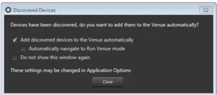
text_image
Discovered Devices Devices have been discovered, do you want to add them to the Venue automatically? ✓ Add discovered devices to the Venue automatically □ Automatically navigate to Run Venue mode □ Do not show this window again These settings may be changed in Application Options CloseFigure 29: Discovered Devices prompt
Offline & Online Operation Explained
Audio Architect has two defined modes of operation: Offline and Online. When operating in Offline mode, system setting changes made in Audio Architect will not be reflected in the system hardware devices in real time; offline changes must be sent to the system devices in a second step, at which point device settings will be updated. Conversely, when operating in Online mode, any changes made in Audio Architect will be reflected in the system devices in real time.
When operating in Offline mode, the Offline Design ribbon is presented at the top of the Main Audio Architect window. From this window, discovered devices can be added to the venue by clicking on them in the Devices tab on the left and dragging them into the Room window on the right (see Figure 30).
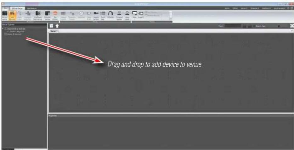
text_image
Drag and drop to add device to venueFigure 30: Main Audio Architect window
Note that when a device is added to the venue, it is automatically removed from the "Discovered" device list. If the "Add discovered devices to the Venue automatically" checkbox was checked upon launching Audio Architect, as previously mentioned, discovered devices were already added to the Venue and this step is not necessary.
Each device added to the venue will have an IP address listed to the left of the amplifier image and a Name ID to the right (see Figure 31). The Name ID can be edited in the Properties menu at the bottom of the window. The number to the left of the Name ID is the HiQnet Device Address. The green circle indicates that the amplifier has been discovered on the network.
TIP: Double clicking a device image will open the device's Main Control panel (see "Main CDi DriveCore Control Panel" on page 34 for more information).
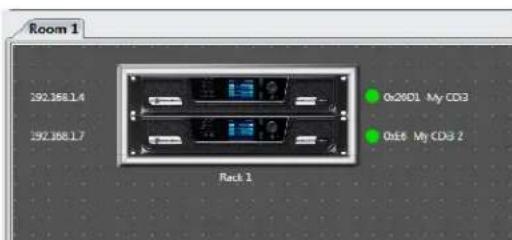
text_image
Room 1 392.188.1.4 392.188.1.7 Rock 1 On20D1 My CD3 On5 My CD3 2Figure 31: Device information
Going Online
You will have to go online in Audio Architect before any changes can be made to device settings.
To go online:
- From the Offline Design ribbon at the top of the Main Audio Architect window, click the Go Online button. The Offline Design and Add Devices ribbons will now be replaced with the Online Operate ribbon and, in some cases, the Match Devices ribbon.
- When going online, the following scenarios are possible:
a. If one or more devices in the venue are not matched AND corresponding devices are available on the network, going online lands in Match Devices mode.
NOTE: Before you can go online with a device, it must be "matched". See "Matching Devices" on page 33 for more information.
b. If all the devices in the venue are matched, going online lands in Synchronize Venue mode. In Synchronize Venue mode, Receive and Send icons will appear for each device in the venue, as well as for a rack if more than one device has been added (see Figure 32). This provides the ability to send/receive data either to/from a single device, or to/from all devices within the rack with a single click.
c. If no devices require matching or synchronization, going online lands in Run Venue mode. In this mode, Audio Architect is online with the devices in the venue and real-time setting changes can be made.
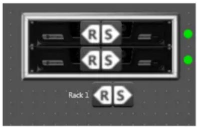
text_image
R S R S Rack 1 R SFigure 32: Send and Receive icons
Matching Devices
The Match Devices ribbon appears at the top of the Main Audio Architect window after clicking on the Go Online button from the Offline Design ribbon, then clicking the Match Devices button from the Online Operate ribbon.
The Match Devices feature allows devices within the venue design to be associated with the hardware devices on the network. If a device image in the venue says "UNMATCHED", the device must be matched before it can be
associated and controlled with Audio Architect. This can usually be accomplished by simply clicking the Auto-Match Venue button (see Figure 33).
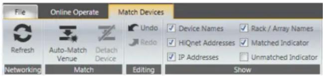
text_image
File Online Operate Match Devices Refresh Auto-Match Venue Detach Device Undo Redo Device Names Rack / Array Names HiQnet Addresses Matched Indicator IP Addresses Unmatched Indicator Networking Match Editing ShowFigure 33: Match Devices ribbon
In the Match Devices ribbon, the following options are available:
- Networking
Clicking the Refresh button will temporarily take Audio Architect offline, then restart the network.
- Match
Clicking the Auto-Match Venue button will automatically match devices on the network with the devices in the Audio Architect venue. Selecting a device then clicking the Detach button removes the device's virtual connection with Audio Architect.
- Editing
Clicking the Undo button will undo the last change made and revert back to the previous state. Clicking the Redo button will redo the last action that was undone.
• Show
Any checked items in this section will be displayed alongside the appropriate devices in the Main Audio Architect window. The available items include Device Names, Rack/Array Names, HiQnet Addresses, IP Addresses, Matched Indicator, and Unmatched Indicator.
Main CDi DriveCore Control Panel
Double-clicking the CDi DriveCore image from the Room window (see Figure 31) will open the Main CDi DriveCore Control panel. Figure 34 shows the 4-channel version of the Main CDi DriveCore Control panel. The CDi DriveCore amplifiers include Digital Signal Processing (DSP), multiple input/output routing options, and a comprehensive diagnostics feature set. All of these features can be accessed from the Main CDi DriveCore Control panel.
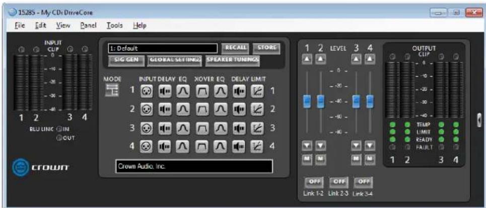
text_image
1528S - My CDi DriveCore File Edit View Panel Tools Help INPUT CLIP 0 1 2 3 4 BLU LINK ON OUT CROWIT 1: Default RECALL STORE SIG GEN GLOBAL SETTINGS SPEAKER TUNINGS MODE INPUT DELAY EQ XOVER EQ DELAY LIMIT 1 2 3 4 Crown Audio, Inc. OUTPUT CLIP 0 -90 -90 -90 -90 TEMP LIMIT READY FAULT 1 2 3 4 OFF OFF OFF Link 1-2 Link 2-3 Link 3-4Figure 34: Main CDi DriveCore Control panel (4-channel amp model shown)
1. Level Faders
These faders set the output signal level of each channel and correspond with the levels set using the front panel ENCODER.
2. Link Buttons
Links the Level faders and Mute buttons for ganged operation.
3. Mute Buttons
Mutes the corresponding output channel.
4. Input Meters
These meters display input signal level, and range from -40dBFS to 0dBFS. Each input channel has the following monitors:
- Peak and RMS Meters: The wider left meter shows RMS level and the right meter shows peak level.
- Clip Indicator: Lights to indicate input clipping.
5. Output Meters
These meters display output signal level, and range from -40dBFS to 0dBFS. The meters are scaled so that 0dBFS is referenced to the full rated output voltage of the amplifier. Each output channel has the following monitors:
- Peak and RMS Meters: The wider left meter shows RMS level and the right meter shows peak level.
- Clip Indicator: Lights to indicate output clipping.
6. Indicators
a. BLU Link (In/Out): Available only on BLU link CDi DriveCore models, these indicators light when the BLU link input and output ports have established a link with the BLU link bus.
b. Temp: Indicates the temperature of an amplifier channel and provides warning when an amplifier channel is too high and near shutdown. These indicators may light one of the following colors:
- Green: Thermal temperature is less than 80^ .
- Yellow: Thermal temperature is between 80-100°C.
- Red: Thermal temperature is greater than 100^ C .
c. Limit: Lights when the amplifier's output signal is being limited by the clip limiter, LevelMAX peak/rms/thermal speaker limiters, or the amp thermal protection limiter.
d. Ready: Lights when the amplifier is on and ready to supply power.
e. Fault: Lights when the amplifier detects a fault and enters a fault state. See "System Protection" on page 72 for more information on the various types of possible faults.
7. DSP Buttons
Double-clicking any of these buttons will open the corresponding DSP control panel, where DSP settings can be edited.
8. Other Buttons
a. Basic/Normal View (Arrow Button): Collapses or expands the window.
b. Mode: Opens the Amplifier Mode Settings panel, where input wiring and output operation can be configured.
c. Signal Generator: Opens the Signal Generator panel.
d. Global Settings: Opens the Global Settings panel (see "Amplifier Information" on page 35).
e. Speaker Tunings: Allows a speaker tuning to be selected for each output to optimize DSP settings for particular speaker models.
f. Recall: Loads a device preset.
g. Store: Stores a device preset.
Many of these functions will be further explained on the following pages.
Amplifier Information
The Global Settings panel can be accessed by clicking the Global Settings button from the Main CDi DriveCore Control panel (Figure 35). The Global Settings panel (Figure 36) displays amplifier information such as current firmware version, power supply temperature, channel temperature, and more.
The following functions can also be configured from the Global Settings panel:
1. Output Labels
These fields allow user-defined names to be entered for the analog output channels for reference.
2. Front Panel Lockout
When turned on, the front panel controls will be locked to prevent tampering. The exception is the Power button, which will remain functional.
TIP: The front panel controls can also be locked directly from the front panel, however, if the front panel has been locked from Audio Architect, it must be unlocked from Audio Architect. See "Security/Front Panel Lockout" on page 66 for more information on locking/unlocking the front panel controls from the front panel.
3. Front Panel Blackout Mode
Turns the front panel display on or off.
4. Amp Status Port
Selects whether a 2Hz square wave heartbeat or +5VDC signal is sent to the Amp Status pin on the AUX port — either can be used to remotely determine amp health/status.
5. Mute Input
Determines which output channels will be muted when using GPIO Input 1 (pin 3). By default, a high condition will cause all checked input channels to mute. Checking the Invert checkbox will invert the polarity/functionality, meaning a low condition will cause all checked inputs to mute.
6. Fault Output
Inverts the polarity/functionality of GPIO Output 1 (pin 1). When checked, GPIO Output 1 will indicate an amp fault when in a low state, rather than the default high state. See "System Protection" on page 72 for more information on faults.
7. Preset Recall Input
Loads one of two presets depending on the high/low state of Input 2 (pin 5) on the GPIO port. By default, these values are set to 0, which disables the function.
8. Manual Aux Output
When this button is switched on, GPIO pin 2 (Output 2) will go high; when the button is off the state will be low. This provides a general purpose output which can be used to control many external devices such as relays, indicators, PLC system controllers, or any other 3rd party device with logic control inputs. This button can be controlled from its default location on the Global Settings panel, from a user-created custom control panel, using logic functions in Audio Architect, or from a compatible HiQnet wall controller. The state of this button and the resulting output are stored/recalled along with device presets.
9. Power Modes
Use these settings to turn the APD and ACD power saving modes on or off and adjust the behavior of the ACD feature. See "Power Saving Modes" on page 71 for more information.
For more information on using the GPIO control port, see "Using the GPIO Control Port" on page 69.

text_image
1: Default SIG GEN GLOBAL SETTINGS RECALL STORE SPEAKER TUNINGSFigure 35: Global Settings button
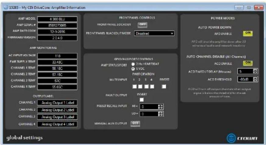
text_image
15285 - My CDI DriveCore Amplifier Information AMP MODEL 4.300 BLU AMP SERIAL # 850173065 AMP DATE CODE 12-3-2016 FRAME VERSION 2.0.4.0 FRMWARE VERSION AMP MONITORING AC INPUT VOLTAGE 118 PWM SUPPLY TEMP 33.48C CHANNEL 1 TEMP 58.18C CHANNEL 2 TEMP 57.15C CHANNEL 3 TEMP 57C CHANNEL 4 TEMP 55.65C OUTPUT LABEL CHANNEL 1 Analog Output 1 Label CHANNEL 2 Analog Output 2 Label CHANNEL 3 Analog Output 3 Label CHANNEL 4 Analog Output 4 Label FRONT PANEL CONTROLS FRONT PANEL LOCKOUT OFF FRONT PANEL BLACKOUTMODE Disabled GPIO/AUX/FORT CONTROLS AMP STATUSFORT 2 Hz/HEAT/BEAT 5 VOC PART CIPATION MUTEN INPUT 1 2 3 4 INVERT FAULT OUTPUT INVERT PRESS B/CALL INPUT HI = 0 LO = 0 MANUAL AUX OUTPUT OFF POWER MODES AUTO POWER DOWN APD ENABLE ON APD will start the amplification down after 20 minutes of audio and network inactivity AUTO CHANNEL DISABLE (All Channels) ACD ENABLE CON- ACD TIMOUT/DELAY (Minutes) S ACD THRESHOLD -80dB ACD will turn off output channels when output signal is below the threshold of the current pressure of time. global settings CTOUNTFigure 36: Global Settings panel
Configuring Inputs & Outputs in Audio Architect
Assigning Input Sources in Audio Architect
All channels of the CDi DriveCore signal processing share a single Input Selector panel (shown in Figure 38). From this panel, you can select the audio signal that will be routed to each amplifier channel and adjust the levels entering each channel's DSP chain.
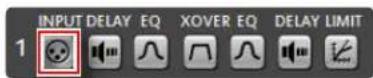
Figure 37: Input button
The Input Selector panel can be accessed by clicking any of the INPUT buttons from the Main CDi DriveCore Control panel (see Figure 37).
1. Levels, Meters, & Clip Indicators
The level faders are used to adjust signal levels entering the DSP chains from the various input sources. The meters in this panel display both peak and RMS levels — the wider left meter shows RMS level and the right meter shows peak level for each channel. The clip indicators light to indicate clipping at the signal point just before the loudspeaker management processing (delays, EQ, crossover, etc.).
2. Input Selector Dropdown Menus
From these dropdown menus, input channel assignments can be selected for each channel. Analog inputs are available for selection in
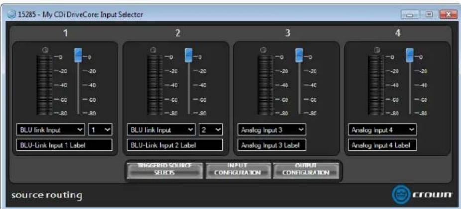
text_image
15285 - My CDi DriveCore: Input Selector 1 BLU link Input 1 BLU-Link Input 1 Label 2 BLU link Input 2 BLU-Link Input 2 Label 3 Analog Input 3 Analog Input 3 Label 4 Analog Input 4 Analog Input 4 Label BIGGERED SOURCE SELECTS INPUT CONFIGURATION OUTPUT CONFIGURATION source routing CROWNFigure 38: Input Selector panel (BLU link CDi DriveCore model shown)
all CDi DriveCore amp models. Mono summed analog options are also available. Additional BLU link channel options are available in BLU link CDi DriveCore amp models. When assigning BLU link channels, a second dropdown menu will appear, where the desired BLU link channel can be selected, as shown in Figure 38. These BLU link channel assignment dropdown menus provide an easier method for assigning BLU link channels, however, note that BLU link channels can also be assigned from the BLU link Input Channel Assignment window (see Figure 41).
3. Input Labels
These fields allow user-defined names to be entered for the analog input channels, which can be used for reference and added to custom control panels.
4. Input Configuration and Output Configuration Buttons
Clicking the Input Configuration button opens the Input Configuration panel, where input levels and analog gain structure can be adjusted (see "Configuring Inputs" on page 37 for more information). Clicking the Output Configuration button (available only in BLU link amp models) opens the BLU link Output Configuration panel, where the amplifier's BLU link output channels can be configured (see "Configuring BLU link Outputs" on page 38 for more information).
5. Triggered Source Selects Button
Pressing this button will open the Triggered Source Selects panel (see Figure 39). This panel makes it easier to program a BSS Contrio Ethernet wall controller to recall up to four source selection states (Trigger A-D), along with input gain settings and on-screen controller labels. See "Programming BSS Contrio Ethernet Wall Controllers" on page 49 for more information on using this panel and configuring Contrio wall controllers
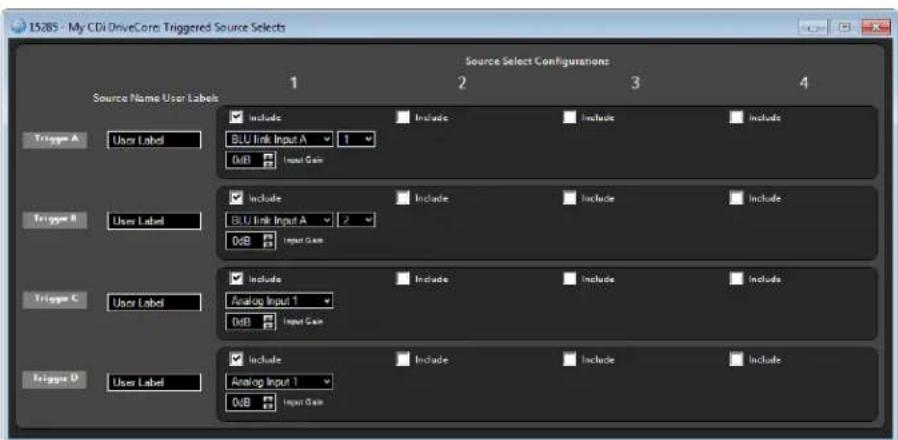
text_image
15.85 - My CDi DriveCore Triggered Source Selects Source Select Configurations 1 2 3 4 Source Name User Labels Include Include Include Include Trigger A User Label BLU link Input A 1 0dB Input Gain Include Include Include Include Trigger B User Label BLU link Input A 2 0dB Input Gain Include Include Include Include Trigger C User Label Analog Input 1 0dB Input Gain Include Include Include Include Trigger D User Label Analog Input 1 0dB Input GainFigure 39: Triggered Source Selects panel
Using HiQnet Audio Architect
Configuring Inputs
The Input Configuration panel can be accessed by clicking the Input Configuration button from the Input Selector panel (see Figure 38).
The Input Configuration panel (Figure 40) allows you to adjust signal levels entering the amplifier from the various sources. The BLU link CDi DriveCore models will display additional BLU link (Network) inputs.
The meters in this panel display both peak and RMS input levels — the wider left meter shows RMS level and the right meter shows peak level for each channel. Input Mute buttons are available for each channel. Network Signal Status LEDs below each BLU link input channel provide confirmation of BLU link signal presence.
The Gain Mode option is used to set the maximum amount of gain the amplifier will provide. The available options are +26 dBu, +34 dBu, and +37 dBu. Note that changes to this setting will affect all channels.
Clicking the Advanced Settings button opens the Advanced Settings panel, where BLU link sample rate and mastership clock priority can be set. See "Configuring BLU link Clock" on page 38 for more information.
If using one of the BLU link CDi DriveCore models, the Audio Routing button will be available in the Input Configuration panel (Figure 40). Clicking the Audio Routing button opens the BLU Link Input Channel Assignment window (see Figure 41). This is the traditional Audio Architect window used for assigning BLU link channels. From this window, any available BLU link audio streams can be assigned to the CDi DriveCore's inputs. Note that CDI DriveCore amplifiers provide an easier method for assigning BLU link input channels directly from the Input Selector panel (see Figure 38).
Figure 40: Input Configuration panel (BLU link model shown)
Figure 41: BLU Link Input Channel Assignment window
Configuring BLU link Clock
The Advanced Settings panel can be accessed by clicking the Advanced Settings button from either the Input Configuration panel (see Figure 40) or from the Output Configuration panel (see Figure 43). From the Advanced Settings panel, BLU link sample rate and mastership clock priority can be set. This panel also displays clock sync status and BLU link input/output connection status. Input/output errors and corrected errors are also displayed and can be reset from this panel. For more information on these parameters, see "Configuring BLU link Settings" on page 22 and "BLU link Status" on page 62.
Configuring BLU link Outputs
Clicking the Output Configuration button from the Input Selector panel (see Figure 38) opens the BLU link Output Configuration panel (see Figure 43). From this panel, audio source signals can be routed ("on-ramped") back onto the BLU link bus as follows:
- Pre-processed audio from the inputs can be routed to the BLU link bus.
NOTE: The audio from the analog inputs will still pass through the amplifier input gain stage. This means the signals will be affected by the Gain Mode setting and the Input Level faders located in the Input Configuration panel (Figure 40) before being sent out to the BLU link bus.
- Amp output channels can be routed to the BLU link bus.
NOTE: The output audio is bussed from a point at the end of the amp's signal processing chain and includes the Transducer Thermal Limiter. This is effectively analogous to taking the audio from the physical output of the amplifier, which feeds the loudspeaker, and routing it onto the BLU link bus.
To route amplifier audio onto the BLU link bus, select the audio source for each output channel using the Audio Source dropdown menus, then select which BLU link channel to route each signal to using the BLU link Channel dropdown menus.
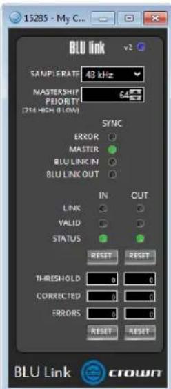
text_image
15285 - My C... BLU link v2 SAMP RATE: 48 kHz MASTERSHIP PEEORTY (704 HIGH BLOW) SYNC ERROR MASTER BLU LINK IN BLU LINK OUT IN OUT LINK VALID STATUS RESET RESET THRESHOLD 0 0 CORRECTED 0 0 ERRORS 0 0 RESET RESET BLU Link crownFigure 42: Advanced Settings panel
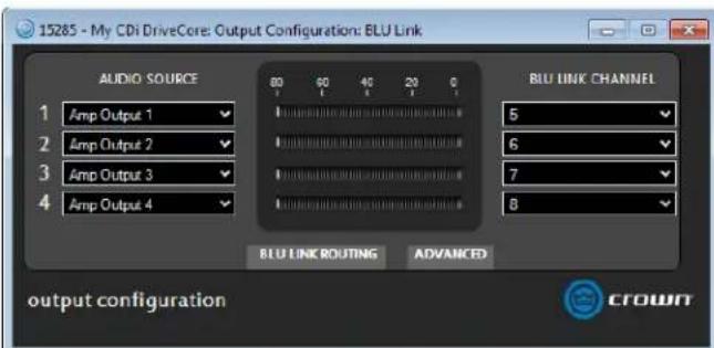
text_image
15285 - My CDi DriveCore: Output Configuration: BLU Link AUDIO SOURCE 1 Amp Output 1 2 Amp Output 2 3 Amp Output 3 4 Amp Output 4 60 60 40 20 0 BLU LINK CHANNEL 5 6 7 8 BLU LINK ROUTING ADVANCED output configuration CROWNFigure 43: BLU link Output Configuration panel
NOTE: Audio Architect also provides the traditional BLU link Output Channel Assignment window (Figure 44) for routing BLU link audio onto the BLU link bus. Either method can be used to assign BLU link output channels.
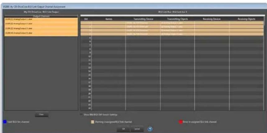
text_image
16200 My CD-DriveCore E/U Link Output Channel Assignment My CD-DriveCore E/U Link Output Output Channel 16200 [ ] AnalogOutput Label 16200 [ ] AnalogOutput Label 16200 [ ] AnalogOutput Label 16200 [ ] AnalogOutput Label BU Link Rate: E/U Link Box 5 Split Names Transmitting Device Transmitting Objects Receiving Device Receiving Objects 1 2 3 4 5 6 7 8 9 10 11 12 13 14 15 16 17 18 19 20 21 22 23 24 Show E/U-SCD ETF switch Settings Valid E/U link channel Warning unsigned E/U link channel Store in-sagged E/U link channel OK CancelFigure 44: BLU Link Output Channel Assignment window
Configuring Amp Wiring & Output Modes in Audio Architect
The CDi DriveCore amplifiers are very capable and flexible amplifiers. From the Amplifier Mode Settings panel, the following items can be configured:
- Inputs can be cascaded ("Y'ed") to multiple outputs.
- Output pairs can be bridged for mono operation.
- Outputs can be independently configured for Low Z or High Z (70V/100V) operation.

Figure 45: Mode button
The Amplifier Mode Settings panel can be accessed by double-clicking the MODE button from the Main CDi DriveCore Control panel (see Figure 45).
Cascading Inputs
The ability to cascade inputs (or "Y" channels) makes the CDi DriveCore Series amps even more flexible. One input can be used to drive some or all of the amplifier outputs (see Figure 46).
NOTE: By cascading the inputs, the corresponding input DSP functions for individual channels will be removed and only the output DSP functions will be available, as shown in Figure 47.
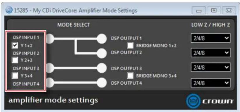
text_image
15285 - My CDi DriveCore: Amplifier Mode Settings MODE SELECT DSP INPUT 1 Y1+2 DSP INPUT 2 Y2+3 DSP INPUT 3 Y3+4 DSP INPUT 4 DSP OUTPUT 1 BRIDGE MONO 1+2 DSP OUTPUT 2 DSP OUTPUT 3 BRIDGE MONO 3+4 DSP OUTPUT 4 LOW Z / HIGH Z 2/4/8 2/4/8 2/4/8 2/4/8 2/4/8 amplifier mode settings crownFigure 46: Use the "Y" checkboxes to cascade input channels
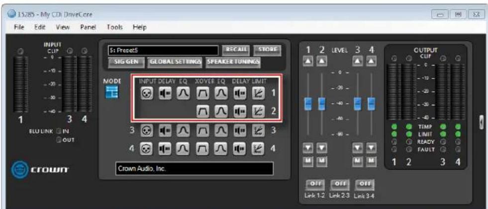
text_image
15285 - My CDI DriveCore File Edit View Panel Tools Help INPUT CLIF 0 -10 -20 -30 -40 1 3 4 S: Preset5 RECAIL STORE SIG GEN GLOBAL SETTINGS SPEAKER TUNINGS MODE INPUT DELAY EQ XOVER EQ DELAY LIMIT 1 2 3 4 Crown Audio, Inc. OUTPUT CLIF 0 -10 -20 -30 -40 TEMP LIMIT READY FAULT 1 2 3 4 OFF OFF OFF Link 1-2 Link 2-3 Link 3-4Figure 47: With the "Y 1+2" box checked, both output Ch.1 and Ch.2 are fed by input Ch.1 and input processing is organized accordingly
Configuring Outputs for Bridge Mono Operation
When more output power is required for the application, output channel pairs can be configured for bridge mono operation. This can be configured in the Amplifier Mode Settings panel (see Figure 48).
When selecting the Bridge Mono option for an output pair, only the odd-numbered input channel will need to be wired.
NOTE: When configured for bridge mono operation, only one channel in the channel pair DSP will be available, as shown in
Figure 49.

text_image
15285 - My CDi DriveCore: Amplifier Mode Settings MODE SELECT DSP INPUT 1 Y 1+2 DSP INPUT 2 Y 2+3 DSP INPUT 3 Y 3+4 DSP INPUT 4 DSP OUTPUT 1 BRIDGE MONO 1+2 DSP OUTPUT 2 2/4/8 Bridge Mono Option 2/4/8 2/4/8 amplifier mode settings CROWNFigure 48: Bridge mono configuration
Configuring Outputs for Low Z/High Z Operation
The CDi DriveCore's output channels can be configured for Low Z or High Z operation. To configure the amplifier for High Z operation, select either the 70V or 100V option (see Figure 50).
NOTE: If an amplifier output channel pair is configured for bridge mono operation and one of the High Z options is selected, the amplifier output will produce 140V or 200V (rather than 70V or 100V).
NOTE: When configured for High Z operation, a 35Hz high-pass filter will automatically be applied to the signal. When configured for Low Z operation, a 10Hz high-pass filter will automatically be applied to the signal.

Figure 49: DSP chain configured for bridge mono operation
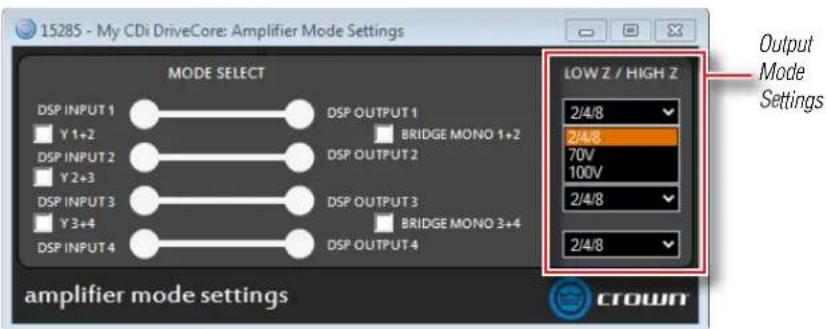
text_image
15285 - My CDi DriveCore: Amplifier Mode Settings MODE SELECT DSP INPUT 1 Y 1+2 DSP INPUT 2 Y 2+3 DSP INPUT 3 Y 3+4 DSP INPUT 4 DSP OUTPUT 1 BRIDGE MONO 1+2 DSP OUTPUT 2 DSP OUTPUT 3 BRIDGE MONO 3+4 DSP OUTPUT 4 LOW Z / HIGH Z 2/4/8 2/4/8 70V 100V 2/4/8 2/4/8 Output Mode Settings amplifier mode settings CROWNFigure 50: Low Z/High Z configuration
NOTE: The full scale output of the amplifier will change depending on the Low Z/High Z setting, as well as the amplifier model (see table).
| Low Z/High Z Setting Full | Scale Voltage RMS |
| Low Z Mode (300W models) 49 | |
| Low Z Mode (600W models) 69.9 | |
| High Z Mode (70V) 70 | |
| High Z Mode (100V) 100 |
Configuring Speaker Tunings in Audio Architect
Speaker tunings apply DSP settings specific to a particular speaker, making it easy to optimize a speaker's performance.
To configure speaker tunings in Audio Architect:
- From the Main CDi DriveCore Control panel, click the Speaker Tunings button.
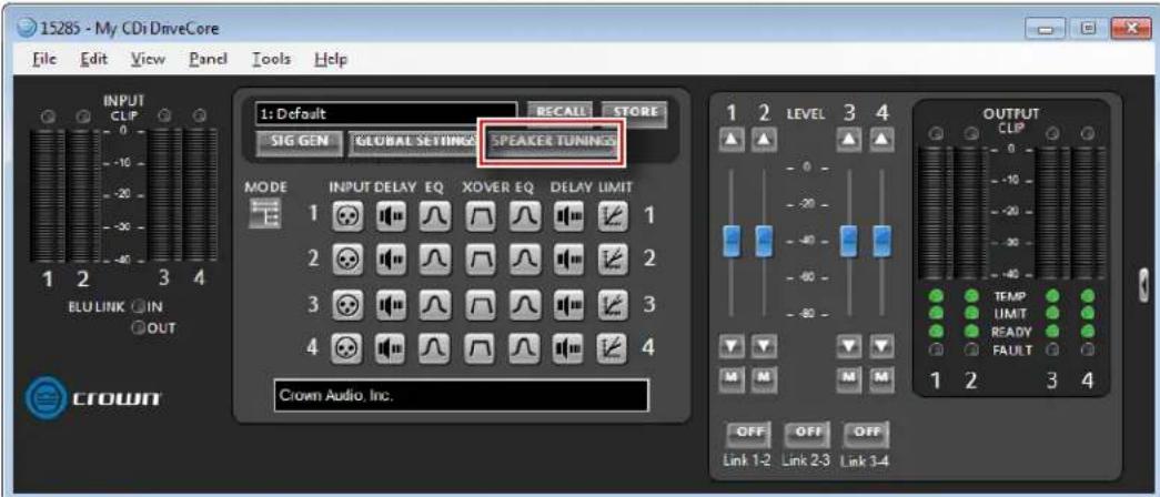
text_image
15285 - My CDi DriveCore File Edit View Panel Tools Help INPUT CLIP 0 -10 -20 -30 -40 1 2 3 4 BLUELINK ○IN ○OUT CROWN 1: Default RECALL STORE SIG GEN GLOBAL SETTINGS SPEAKER TUNINGS MODE INPUT DELAY EQ XOVER EQ DELAY LIMIT 1 2 3 4 Crown Audio, Inc. 1 2 LEVEL 3 4 OUTPUT CLIP 0 -10 -20 -30 -40 TEMP LIMIT READY FAULT 1 2 3 4 OFF OFF OFF Link 1-2 Link 2-3 Link 3-4- Select the speaker series, model, and desired options from the dropdown menus, then click the Apply button.
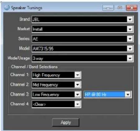
text_image
Speaker Tunings Brand: JBL Market: Install Series: AE Model: AM7315/95 Mode/Usage: 3-way Channel / Band Selections Channel 1: High Frequency Channel 2: Md Frequency Channel 3: Low Frequency HP @ 80 Hz Channel 4:- The example screenshot below shows the Main CDi Control panel with the configured speaker tunings.
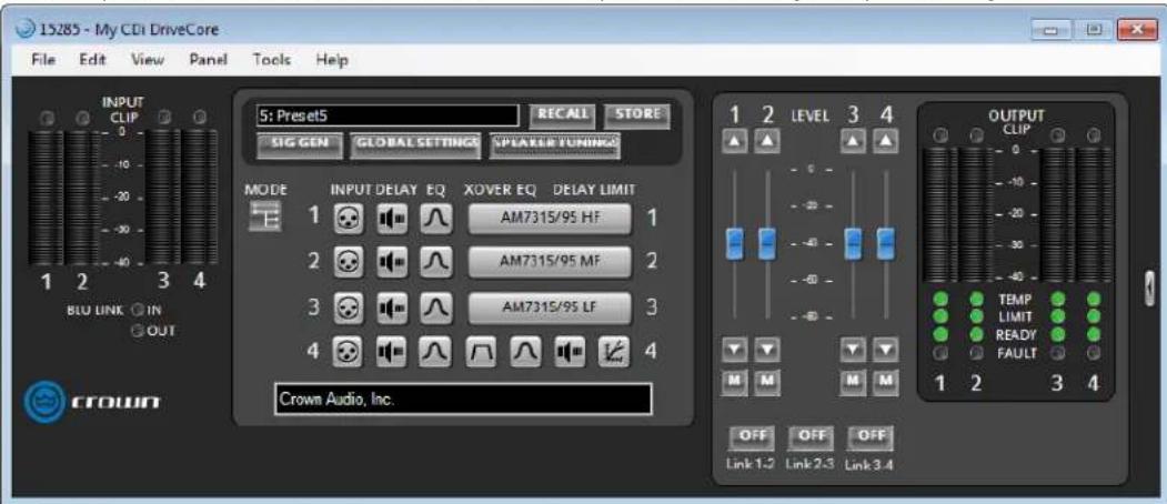
text_image
15285 - My CDi DriveCore File Edit View Panel Tools Help INPUT CLIP 0 -10 -20 -30 -40 1 2 3 4 BLO LINK ○ IN ○ OUT CROWN 5: PresetS RECALL STORE SIG GEN GLOBAL SETTINGS NPLAER TUNING MODE INPUT DELAY EQ XOVER EQ DELAY LIMIT 1 AM7315/95 HF 1 2 AM7315/95 MF 2 3 AM7315/95 LF 3 4 Crown Audio, Inc. 1 2 LEVEL 3 4 OUTPUT CLIP 0 -10 -20 -30 -40 -50 -60 -70 -80 M M M M OFF OFF OFF Link 1.2 Link 2.3 Link 3.4TIP: To clear a tuning, double-click the tuning block in the configuration map and then press the Clear button.
Crossover Panel
The Crossover provides infinite impulse response (IIR) filters. Each filter has up to +24/-60dB of gain. The Crossover panel is used to edit the crossover settings and can be accessed by double-clicking the XOVER button from the Main CDi DriveCore Control panel (see Figure 51).
NOTE: If speaker tunings have been configured for a channel, the Crossover panel will not be available for that channel.
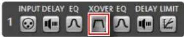
Figure 51: XOVER button
Available low-pass/high-pass filter types:
- Bessel: 12dB/oct, 18dB/oct, 24dB/oct, 30dB/oct, 36dB/oct, 42dB/oct, 48dB/oct
- Butterworth: 6dB/oct, 12dB/oct, 18dB/oct, 24dB/oct, 30dB/oct, 36dB/oct, 42dB/oct, 48dB/oct
- Linkwitz-Riley: 12dB/oct, 24dB/oct, 36dB/oct, 48dB/oct
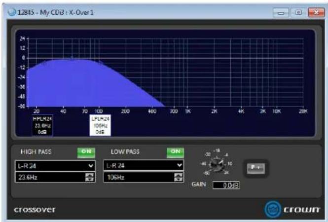
area
| Frequency | Value | | --------- | ----- | | L-R 24 | 23.6Hz | | LPR 24 | 100Hz | | Other | 26Hz |Figure 52: X-Over panel
FIR Filters
For advanced users, the Crown CDi DriveCore amplifiers provide support for importing or entering FIR filter coefficients. Support is provided for one FIR filter per amplifier channel using up to 1024 taps per filter.
The FIR filter window can be accessed by holding the alt key on the keyboard while double-clicking the Crown logo on the bottom-right corner of the Main CDi DriveCore Control panel (see
Figure 53).
For additional information on using FIR filters with the CDi DriveCore amplifiers, please contact Crown Technical Support.
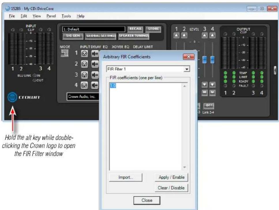
text_image
15285 - My CDi DriveCore File Edit View Panel Tools Help INPUT CLIF 1: Default RECALL STORE SIG GEN GLOBAL SET/INGS SPEAKER TUNINGS MODE INPUT DELAY EQ XOYER EQ DELAY LIMIT 1 2 LEVEL 3 4 2 3 4 3 4 CROWN CROWN Audio, Inc. Arbitrary FIR Coefficients FIR Filter 1 FIR coefficients (one per line) 1.0 Import... Apply / Enable Clear / Disable Close Hold the alt key while double-clicking the Crown logo to open the FIR Filter windowFigure 53: The FIR Filter window
Input/Output EQ Panels
The CDi DriveCore amplifiers offer an Input (pre-Crossover) and Output (post-Crossover) EQ for each channel. The Output EQs are generally used for speaker tunings, and the Input EQs are used for additional filtering if required for the application. The Input EQ panel can be accessed by clicking the Input EQ button, and the Output EQ panel can be accessed by clicking the Output EQ button from the Main CDi DriveCore Control panel (see Figure 54).
Figure 54: Input and Output EQ buttons
The Input and Output EQs each provide up to 8 bands per channel. You can select filter type, frequency, boost/cut, and width or slope. The EQ's frequency response can be edited by typing in parameters, using the UP and DOWN buttons, or clicking and dragging in the graph (see Figure 55).
NOTE: If speaker tunings have been configured for a channel, the Output EQ panel will not be available for that channel.
Available options/parameters:
- Off/On
Turns the EQ on or off. - Type
Selects the type of filter for the band. See available filter types listed below. - Slope (3 - 15 dB/Oct)
Sets the slope rate of the band for Shelf-type filters.
• Frequency (3 – 15 dB/Oct)
Sets the center/corner frequency of the band. - Gain (±20dB)
Sets the amount of gain (boost/cut) applied to the band. - Width (0.10 - 32)
Sets the width of the band for Bell-type filters, or adjusts the resonant peak for 2nd Order Lowpass/Highpass filters. - Clear
Use these buttons to reset a band's settings back to default.
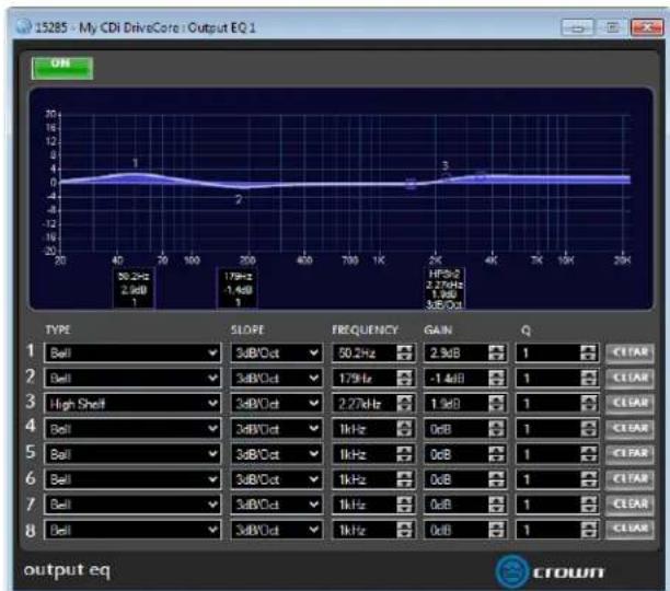
line
| Frequency | Value | | --------- | ----- | | 1 | 50.2Hz | | 2 | 2.9dB | | 3 | 1.79Hz | | 4 | -1.4dB | | 5 | 3.8dB | | 6 | 3.8dB | | 7 | 3.8dB | | 8 | 3.8dB |Figure 55: EQ panel
Available filter types:
• Bell
- Low Shelf
• High Shelf
- Lowpass BW1 (Butterworth 6dB/oct filter)
• Highpass BW1 (Butterworth 6dB/oct filter)
- Lowpass 2nd Order (6-12dB/oct filter with variable resonant peak using the Width parameter)
- Highpass 2nd Order (6-12dB/oct filter with variable resonant peak using the Width parameter)
- Allpass 1 (90° phase shift)
- Allpass 2 (180° phase shift)
Input/Output Delay Panels
The CDi DriveCore Series amplifiers offer an Input (pre-Crossover) and Output (post-Crossover) Delay for each channel. The Output delay is typically used for driver alignment and provides up to 100ms of delay time per channel. The Input Delay provides up to 1 second of additional delay time and can be used for delaying the system to the stage backline, delay fills, or whenever more delay time is required than the Output Delay has to offer. Delay can be adjusted in seconds, feet, or meters (see Figure 57).
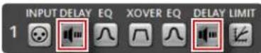
Figure 56: Input and Output Delay buttons
The Input Delay panel can be accessed by clicking the Input Delay button, and the Output Delay panel can be accessed by clicking the Output Delay button from the Main CDi DriveCore Control panel (see Figure 56).
NOTE: If speaker tunings have been configured for a channel, the Output Delay panel will not be available for that channel.
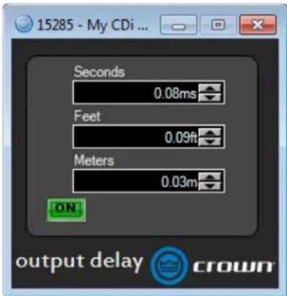
text_image
15285 - My CDi ... Seconds 0.08ms Feet 0.09ft Meters 0.03m ON output delay crownFigure 57: Input Delay panel
LevelMAX Panel
The LevelIMAX panel contains the entire LevelIMAX suite of limiters, which consist of a peak voltage limiter, RMS power limiter, and transducer thermal limiter (see Figure 59).
The LevelIMAX panel can be accessed by double-clicking the LevelIMAX button from the Main CDi DriveCore Control panel (see Figure 58).
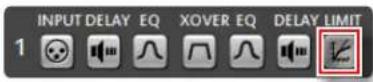
Figure 58: LevelMAX button
NOTE: If speaker tunings have been configured for a channel, the LevelMAX panel will not be available for that channel.
Available options/parameters:
- LevelMAX (Off, On)
Turns the limiters on or off.
- Mode (Auto, Advanced)
Sets whether certain parameters will be set automatically or available for manual configuration. The following Mode options are available:
Auto Mode – When this option is selected, the software determines the best settings based on the signal characteristics. You can modify only the RMS Threshold, Thermal Threshold, and Thermal Time Constant. All other parameters will be set automatically.
Advanced Mode - Selecting this option allows the parameters which are set automatically when "Auto" mode is selected to be manually adjusted. This includes Peak Threshold, Peak Release, and RMS Release.
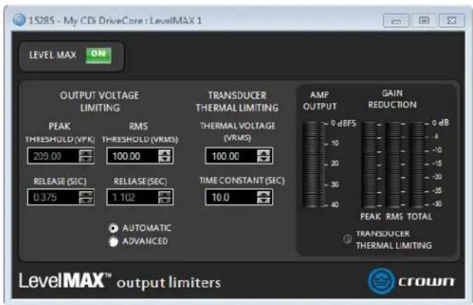
text_image
15285 - My CDi DriveCore : LevelMAX 1 LEVEL MAX ON OUTPUT VOLTAGE LIMITING PEAK THRESHOLD (VPK) 209.00 RELEASE (SEC) 0.375 RMS THRESHOLD (VRMS) 100.00 RELEASE (SEC) 1.102 AUTOMATIC ADVANCED TRANSDUCER THERMAL LIMITING THERMAL VOLTAGE (VRMS) 100.00 TIME CONSTANT (SEC) 10.0 AMP OUTPUT GAIN REDUCTION 0 dBFS 0 dB 10 20 30 40 PEAK RMS TOTAL TRANSDUCER THERMAL LIMITING LevelMAX™ output limiters crownFigure 59: LevelMAX panel
- Peak Threshold (1 - 200 VPK)
Sets the peak level, in absolute voltage, which the limiter will allow
from the amplifier. In Automatic mode, the Peak Threshold value is automatically determined from the defined RMS threshold and the low pass frequency defined in the crossover.
- Peak Release (0 – 10 seconds)
Sets the release time of the peak limiter. The release time is defined as the time it takes the limiter to increase the output signal by 20dB.
• RMS Threshold (1 – 400 VRMS)
Sets the RMS level, in absolute voltage, which the limiter will allow from the amplifier. The RMS Threshold should be set to correspond to the short term (2 hour) power handling of the transducer or system.
• RMS Release (0 – 10 seconds)
Sets the release time of the RMS limiter. The release time is defined as the time it takes the limiter to increase the output signal by 20dB
• Thermal Voltage (1 - 500V)
Sets the long-term output power limit of the amplifier to what the loudspeaker load can handle without overheating and going into thermal compression. This is based on the AES power/voltage ratings of drivers outlined in the AES2-2012 standard.
• Thermal Response (1 - 600 sec)
Sets the time it takes for the thermal limiter to adjust output voltage. This is based on the AES power/voltage ratings of drivers outlined in the AES2-2012 standard.
- Metering
These meters display levels in dBFS and include Amp Output (peak level on the left meter and RMS level on the right), Gain Reduction (peak, RMS, and total), and Thermal Limiting amount. The Transducer Thermal Limiting indicator lights to indicate the Thermal Threshold has been exceeded.
NOTE: The LevelMax limiters include sidechain EQ for advanced speaker tunings. Sidechain EQ parameters are not user adjustable.
For more information on the LevelMAX limiters and how to set the parameters, see the LevelMAX white paper available at www.crownaudio.com.
About the Transducer Thermal Limiter
The Transducer Thermal Limiter limits the long-term output power of the amplifier to what the loudspeaker load can handle without overheating and going into thermal compression. You can set the voltage level at which the thermal limiter engages, and the thermal response time. Your loudspeaker manufacturer might be able to provide this information.
Signal Generator Panel
The signal generator can be used to tune or troubleshoot loudspeakers connected to the amplifier. The Signal Generator panel (Figure 61) can be accessed by clicking the Signal Generator button from the Main CDi DriveCore Control panel (see Figure 60).
Available options/parameters:
• Signal Generator Button (Off, On)
Turns the signal generator on or off.
• Amplitude Fader (-60dBFS to 0dBFS)
Adjusts the global level of the signal generator.
- Mixer Faders (-80dBFS to 0dBFS)
Adjust the individual signal generator levels feeding each DSP chain.
- Mute Buttons (Off, On)
Mutes the signal generator signal feeding each DSP chain.
- Type (Pink, White, Sine)
Selects the type of signal to be generated.
• Frequency (20Hz – 20kHz)
Selects the sine tone frequency when the "Sine" type has been selected.
NOTE: Signal Generator settings are stored with device presets.
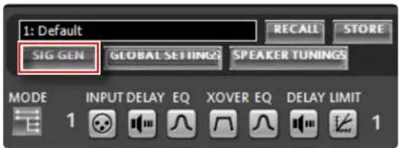
text_image
1: Default SIG GEN GLOBAL SETTINGS SPEAKER TUNINGS MODE INPUT DELAY EQ XOVER EQ DELAY LIMIT 1 1Figure 60: Signal Generator button
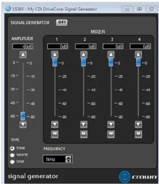
text_image
15285 - My CDi DriveCore: Signal Generator OFF MIXER AMPLITUDE -60dB 1 0dB 2 0dB 3 0dB 4 0dB -0 -0 -0 -0 -0 -20 -20 -20 -20 -40 -40 -40 -40 -60 -60 -60 -60 -60 -60 -80 -80 -80 -80 M M M M TYPE ● PINK ○ WHITE ● SINF FREQUENCY 1kHz signal generator CROWNFigure 61: Signal Generator panel (4-channel amp model shown)
Managing Device & Preset Files
Using Audio Architect, a single amplifier preset can be backed up to a computer as a "preset file", or all amplifier presets and applicable settings can be backed up as a "device file". It is good practice to backup the amplifier's user presets and device settings for safe keeping whenever completing the setup and optimization of a loudspeaker system.
To save a preset or device file in Audio Architect:
-
Go online with the device. You must be online during this operation or the saved settings will not reflect the settings in the actual device. See "Going Online" on page 33 for instructions on going online.
-
Open the Main CDi DriveCore Control panel.
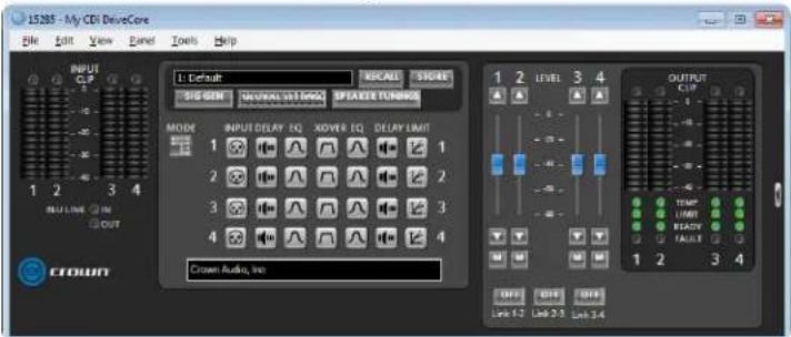
text_image
J5285 - My CDI DriveCore File Edit View Band Tools Help INPUT CCP 1 Default SUS GND GLOBAL SET EMEA SPXAGE TURNOCK MODE INPUT DELAY EQ XOVER EQ DELAY LIMIT 1 2 3 4 CROWN Audio, Inc OUTPUT CLIP 1 2 LEVEL 3 4 OFF QFF QFF Link 1.2 Link 2.3 Link 3.4- Select "File | Save | Device File" to save a device file. Or, select "File | Save | Preset File" to save a single preset as a preset file.
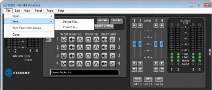
text_image
15.285 - My CDI DriveCore File Edit View Panel Tools Help Open Save Point Parameter Values Close Device File... Preset File... INPUT/DELAY 10 ROVER 10 DELAY LIMIT 1 2 3 4 CROWN Audio, Inc. EFFECTS OUTPUT CLIP TEMP LIMIT REACH FAULT 1 2 3 4 Lift-1:2 Lift-2:3 Lift-3:4- If saving a device file, proceed to the next step. If saving a preset file, the below window will appear. From the "Save this preset:" dropdown menu, select the preset you wish to save. Click Select, then select the desired folder location on the hard drive, name the file, then click Save. Now click OK. The preset file is now saved.
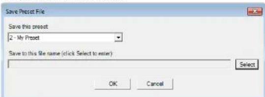
text_image
Save Preset File Save this preset 2 - My Preset Save to this file name (click Select to enter) Select OK Cancel- When the Save As prompt appears, select the desired folder location on the hard drive, name the file, then click Save. The device file is now saved.
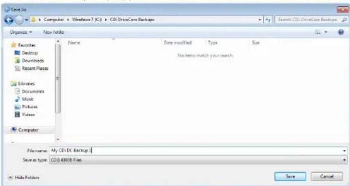
text_image
Save As Computer + Windows 7 (C:) + CDI DriveCore Backups Organize - New Index Favorites Desktop Downloads Recent Places Libraries Documents Music Pictures Videos Computer Name Date modified Type Size File item to match your search. Filename: My CDI-DC Backup 1 Save as type: CDI 49008 Files Save CancelTo open a preset or device file in Audio Architect:
-
Go online with the device. You must be online for the settings to be sent down to the actual device. See "Going Online" on page 33 for instructions on going online.
-
Open the Main CDi DriveCore Control panel.
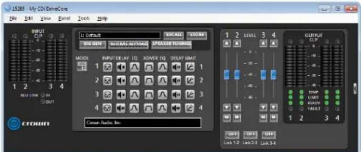
text_image
15285 - My CDx DriveCore File Edit View Band Tools Help INPUT CLIP Default SINO GEN MODRAC MTINUM SPEACE TURNOG MODE 1 INPUT DELAY EQ XOVER EQ DELAY LIMIT 2 3 4 Crown Audio Inc. 1 2 LEVEL 3 4 OUTPUT CLIP 1 2 3 4 OUT LINK 1.2 Link 2.3 Link 3.4- Select "File | Open | Device File" to open a device file. Or, select "File | Open | Preset File" to open a preset file.
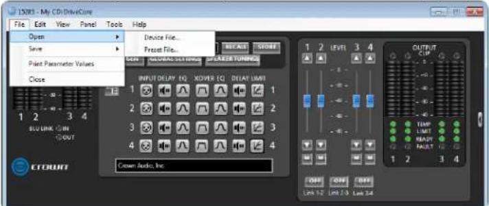
text_image
1503 - My CD DriveCure File Edit View Panel Tools Help Open Save Print Parameter Values Close Device File... Reset File... INPUT DELAY FQ XOVER CQ DELAY LIMIT 1 2 3 4 2 3 4 Crown Audio, Inc. OUTPUT CLIP TEMP LIMITD REPEAT FAULT 1 2 3 4 OFF OFF OFF Lift 52 Lift 2.3 Lift 3.4- If opening a device file, proceed to the next step. If opening a preset file, the below window will appear. From the "Load into preset:" dropdown menu, select the preset location to which you wish to load the preset. Click Select, navigate to the folder containing the preset file, select the file, then click Open. Now click OK. The preset file has now been loaded.
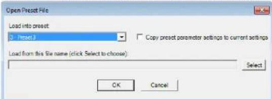
text_image
Open Preset File Load into preset 3 - Preset3 Copy preset parameter settings to current settings Load from this file name (click Select to choose) Select OK Cancel- When the Open prompt appears, navigate to the folder containing the device file, select the file, then click Open. The device file has now been opened and all presets and applicable settings will be reflected in the device.
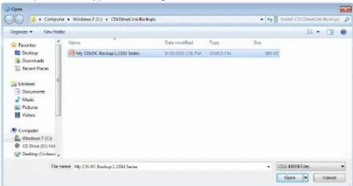
text_image
Open Computer > Windows 7 (C:) > CD drivesCore Backups Organize > New folder Favorites Desktop Downloads Recent Places Libraries Documents Music Pictures Videos Computer Windows 7 (C:) CD Drive (D:) Vnt Desktop (V):Windows Name Data modified Type Size My CDI-DC Backup LCD3 Series 8/10/2016 1:36 PM 2016/23 File 809 KB File name: My CDI DC Backup L CD3 Series CD3 40010 Files Open CancelProgramming BSS Contrio Ethernet Wall Controllers
The BSS Audio Soundweb Contrio Ethernet wall controllers can be used to control many of the parameters and functions in a CDi DriveCore amplifier. At the time of this writing, there are four Ethernet Contrio controller models available. Contrio controllers come in black or white, with US and EU versions available (black US models shown).
EC-V EC-4B EC-4BV EC-8BV
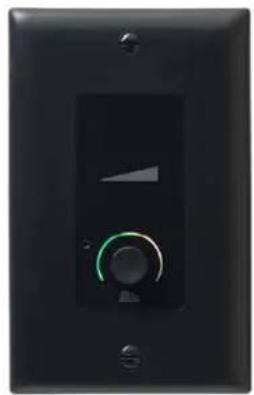
natural_image
Close-up of a black electrical control panel with a green circular dial and indicator lights (no text or symbols visible)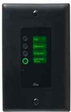
text_image
No Close of Approx Up and Down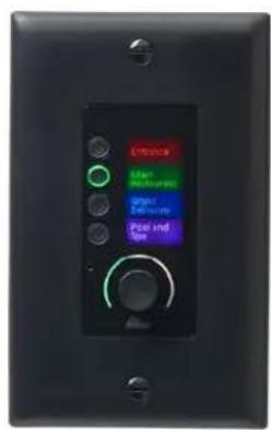
text_image
Unnatural Main Rem Outputs Green Outer lines Pose and Eye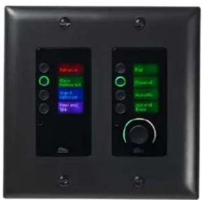
text_image
Balance End Platform End Software Pool and SBS For Closed-All Non-All Standard BaseTo program a Contrio Ethernet wall controller:
- Launch Audio Architect.
- The Contrio controller must be on the same network as the CDi DriveCore amp and the computer running Audio Architect. If using a DHCP server, the network settings should be automatically configured correctly. If using static IP addressing, use the NetSetter application to configure the Contrio controller's network settings. See "Configuring the Network using NetSetter" on page 25 for more information.
- If the CDi DriveCore amp and Contrio wall controller are already visible in Audio Architect's Room window, skip to step 5. If they are not visible, select the "Devices" tab in the lower-left corner of the Main Audio Architect window. Any detected HiQnet devices will appear under the "Discovered" menu tree on the left.
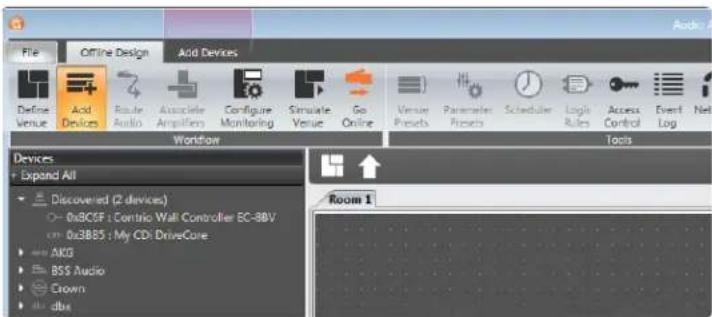
text_image
File Offline Design Add Devices Define Venue Acid Devices Route Audio Associate Amplifiers Configure Monitoring Simulate Venue Go Online Venue Presets Parameter Presets Scheduler Logic Rules Access Control Event Log Net Workflow Tools Devices Expand All Discovered (2 devices) 0x3C05F: Contrio Wall Controller EC-88V cm 0x38BS : My CDI DriveCore AKIQ BSS Audio Crown dbx Room 1- Add the Contrio controller to the Audio Architect venue by dragging it from the "Discovered" menu tree to the Room window. Add the CDi DriveCore amp as well if it has not already been added.
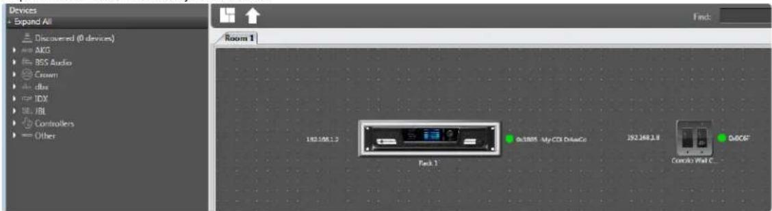
text_image
Devices Expand All Discovered (0 devices) AKG BSS Audio Crown dbox TJX JBL Controllers Other Find: Room 1 192.168.1.3 Pack 1 Go3885 - My CDI DriveCo 192.168.1.8 Go40F Combo Wall C...-
Double-click the amp image to open the Main CDi DriveCore Control panel.
-
Click on one of the Input buttons.
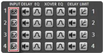
text_image
INPUT DELAY EQ XOVER EQ DELAY LIMIT 1 2 3 4- Click on Triggered Source Selects.
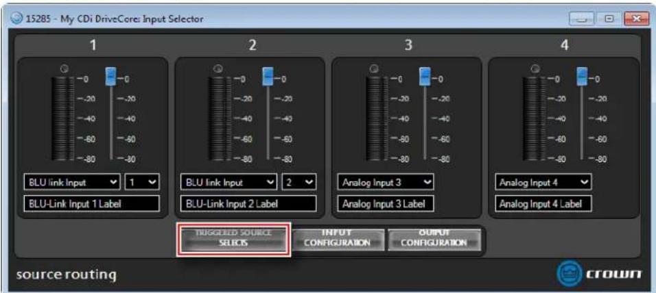
text_image
15285 - My CDi DriveCore: Input Selector 1 BLU link Input 1 BLU-Link Input 1 Label 2 BLU Link Input 2 Label 3 Analog Input 3 Analog Input 3 Label 4 Analog Input 4 Analog Input 4 Label TUGGILD SOURCE SELECTS INPUT CONFIGURATION OUTPUT CONFIGURATION source routing CROWN- The Triggered Source Selects panel provides an easier, more efficient method for programming a Contrio wall controller to control input source selection of a CDi DriveCore amp. There are four different source selection states: Trigger A–Trigger D. The input channels are displayed along the top (4-channel amp model shown). Type a user label for each triggered state—these labels will be displayed on the Contrio controller's screen. Check the Include checkbox for each input channel that should be affected when recalling each triggered state. Set the desired input source and level for each input for each triggered state. Leave this panel open, close other open panels, then proceed to the next step.
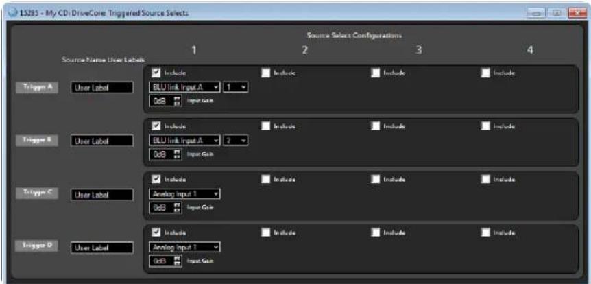
text_image
LS285 - My CDi DriveCore Triggered Source Selects Source Select Configurations 1 2 3 4 Source Name User Labels ✓ Include BLU link Input A 1 0x8 Include Include Include Include ✓ Include BLU link Input A 2 0x8 Include Include Include Include ✓ Include Analog Input 1 0x8 Include Include Include ✓ Include Analog Input 1 0x8 Include Include Include ✓ Include Input Gain- Go back to the Room window and double-click the Contrio Wall Controller image to open the Contrio Wall Controller window.
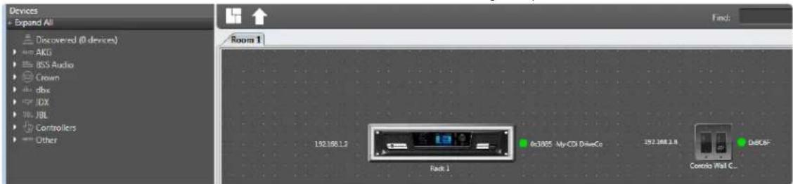
text_image
Devices Expand All Discovered (0 devices) AKG BSS Audio Crown dbx IDX JBL Controllers Other Find: Room 1 192.168.1.2 Fack 1 0x3805 - My CDI DriveCo 192.168.1.4 Control Wall C... D&OFC- Select the desired mode at the top of the Contrio Wall Controller window. See the help file in Audio Architect for descriptions of the different modes.

text_image
Room 1 /159510 Contrio Wall Controller EC-BBV Model: Single Zone Zone 1 Zone Color: Red Align Two Side Control Parameters / Soundproof Condition Period Align Two Side Control Parameters / Soundproof Condition Period Align Two Side Control Parameters / Soundproof Condition Period Align Two Side Control Parameters / Soundproof Condition Period Align Two Side Control Parameters / Soundproof Condition Period Align Two Side Control Parameters / Soundproof Condition Period Red White Unspecified Red Red White Unspecified Red Red White Unspecified Red Red White Unspecified Red Red White Unspecified Red Red White Unspecified Red- Ctrl+click+drag the Trigger A button to the first assignment slot. Repeat for any other programmed triggers, dragging them into the remaining slots. Make any other desired program changes in the Contrio Wall Controller window, such as changing the controller's button or label colors.
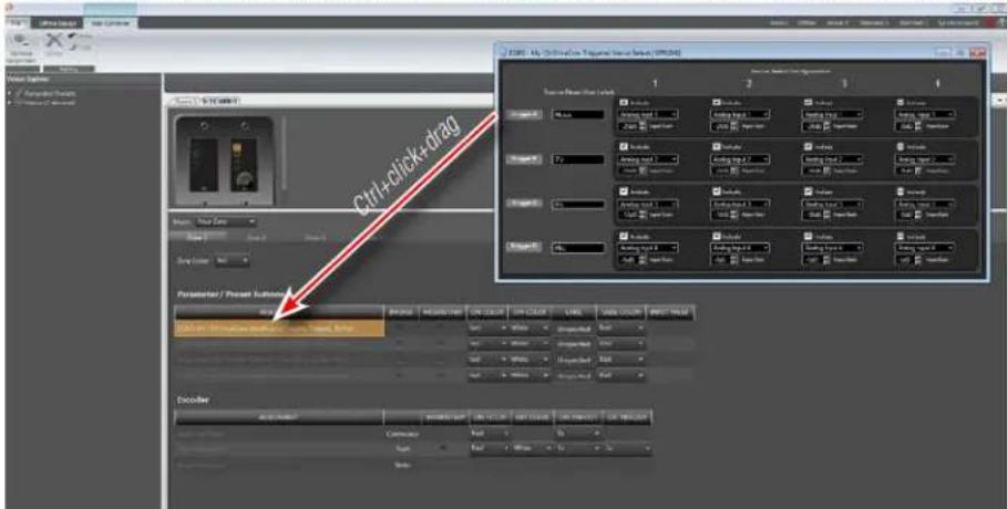
text_image
Ctrl+click+drag Parameter / Preset Substr Encoder 1 2 3 4 5 6 7 8 9 10 11 12 13 14 15 16 17 18 19 20 21 22 23 24 25 26 27 28 29 30 31 32 33 34 35 36 37 38 39 40 41 42 43 44 45 46 47 48 49 50 51 52 53 54 55 56 57 58 59 60 61 62 63 64 65 66 67 68 69 70 71 72 73 74 75 76 77 78 79 80 81 82 83 84 85 86 87 88 89 90 91 92 93 94 95 96 97 98 99 100- To perform more complex programming of a Contrio wall controller, expand the menu tree on the left and find the parameters to assign to the controller, then drag and drop them to the desired assignment slots in the Contrio Wall Controller window.
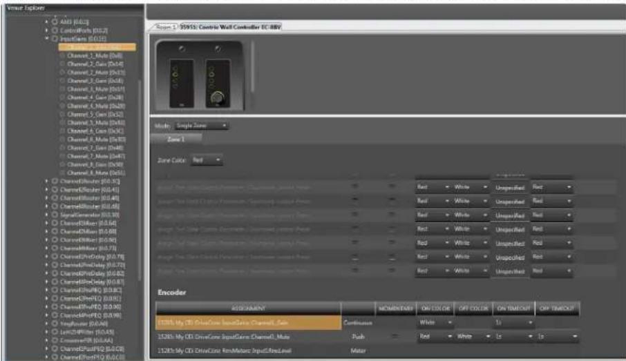
text_image
Lower Explorer AMD (0.012) ControlBox (0.0.7) InputBox (0.0.13) Channel_1_Mate (0x1) Channel_2_Cain (0x4) Channel_3_Cain (0x10) Channel_4_Cain (0x16) Channel_5_Cain (0x22) Channel_6_Cain (0x29) Channel_7_Mate (0x36) Channel_8_Cain (0x44) Channel_9_B_Mate (0x51) Channel_10_B_Mate (0x58) Channel_11_B_Mate (0x65) Channel_12_B_Mate (0x72) Channel_13_B_Mate (0x79) Channel_14_B_Mate (0x86) Channel_15_B_Mate (0x93) Channel_16_B_Mate (0x99) Channel_17_B_Mate (0x106) Channel_18_B_Mate (0x113) Channel_19_B_Mate (0x120) Channel_20_B_Mate (0x127) Channel_21_B_Mate (0x134) Channel_22_B_Mate (0x141) Channel_23_B_Mate (0x148) Channel_24_B_Mate (0x155) Channel_25_B_Mate (0x162) Channel_26_B_Mate (0x169) Channel_27_B_Mate (0x176) Channel_28_B_Mate (0x183) Channel_29_B_Mate (0x190) Channel_30_B_Mate (0x197) Channel_31_B_Mate (0x204) Channel_32_B_Mate (0x211) Channel_33_B_Mate (0x218) Channel_34_B_Mate (0x225) Channel_35_B_Mate (0x232) Channel_36_B_Mate (0x239) Channel_37_B_Mate (0x246) Channel_38_B_Mate (0x253) Channel_39_B_Mate (0x260) Channel_40_B_Mate (0x267) Channel_41_B_Mate (0x274) Channel_42_B_Mate (0x281) Channel_43_B_Mate (0x288) Channel_44_B_Mate (0x295) Channel_45_B_Mate (0x302) Channel_46_B_Mate (0x309) Channel_47_B_Mate (0x316) Channel_48_B_Mate (0x323) Channel_49_B_Mate (0x330) Channel_50_B_Mate (0x337) Channel_51_B_Mate (0x344) Channel_52_B_Mate (0x351) Channel_53_B_Mate (0x358) Channel_54_B_Mate (0x365) Channel_55_B_Mate (0x372) Channel_56_B_Mate (0x379 Channel_57_B_Mate Channel_58_B_Mate Channel_59_B_Mate Channel_60_B_Mate Channel_61_B_Mate Channel_62_B_Mate Channel_63_B_Mate Channel_64_B_Mate Channel_65_B_Mate Channel_66_B_Mate Channel_67_B_Mate Channel_68_B_Mate Channel_69_B_Mate Channel_70_B_Mate Channel_71_B_Mate Channel_72_B_Mate Channel_73_B_Mate Channel_74_B_Mate Channel_75_B_Mate Channel_76_B_Mate Channel_77_B_Mate Channel_78_B_Mate Channel_79_B_Mate Channel_80_B_Mate Channel_81_B_Mate Channel_82_B_Mate Channel_83_B_Mate Channel_84_B_Mate Channel_85_B_Mate Channel_86_B_Mate Channel_87_B_Mate Channel_88_B_Mate Channel_89_B_Mate Channel_90_B_Mate Channel_91_B_Mate Channel_92_B_Mate Channel_93_B_Mate Channel_94_B_Mate Channel_95_B_Mate Channel_96_B_Mate Channel_97_B_Mate Channel_98_B_Mate Channel_99_B_Mate Channel_PoC(0.0.3) Channel_PoC(0.4.4) Channel_PoC(0.4.8) Channel_PoC(0.5.1) SignalGenerator(0.5.3) SignalDriver(0.5.6) SignalDriver(0.5.9) SignalDriver(0.5.12) SignalDriver(0.5.17) SignalDriver(0.5.24) SignalDriver(0.5.29) SignalDriver(0.5.35) SignalDriver(0.5.41) SignalDriver(0.5.47) SignalDriver(0.5.53) SignalDriver(0.5.59) SignalDriver(0.5.65) SignalDriver(0.5.71) SignalDriver(0.5.77) SignalDriver(0.5.83) SignalDriver(0.5.89) SignalDriver(0.5.94) SignalDriver(0.5.99) SignalDriver(0.6.1) SignalDriver(0.6.2) SignalDriver(0.6.3) SignalDriver(0.6.4) SignalDriver(0.6.5) SignalDriver(0.6.6) SignalDriver(0.6.7) SignalDriver(0.6.8) SignalDriver(0.6.9) SignalDriver(0.7) SignalDriver(0.7.1) SignalDriver(0.7.2) SignalDriver(0.7.3) SignalDriver(0.7.4) SignalDriver(0.7.5) SignalDriver(0.7.6) SignalDriver(0.7.7) SignalDriver(0.7.8) SignalDriver(0.7.9) SignalDriver(0.8) SignalDriver(0.8.1) SignalDriver(0.8.2) SignalDriver(0.8.3) SignalDriver(0.8.4) SignalDriver(0.8.5) SignalDriver(0.8.6) SignalDriver(0.8.7) SignalDriver(0.8.8) SignalDriver(0.8.9) SignalDriver(1) Encoder: ASCRAMENT MONDAYDAY ON COLOR OFF COLOR ON TIMEOUT OFF TIMEOUT 1:35% My CD DriveCore SourceCore Channel_Sat Continuous White To 1:3% 1:3% My CD DriveCore SourceCore Channel_Like Push Red White To To 1:3% 1:3% My CD DriveCore ResMotor InputResLevel MotorTIP: An alternative method for assigning parameters to the Contrio controller is to go back to the Room window, open the CDi DriveCore panel that contains the controls to assign, then go back to the Contrio Wall Controller window and ctrl+click+drag each parameter from the CDi DriveCore panel to the desired controller assignment slot.
-
Once programing is complete, go back to the Room window and click "Go Online" in the Offline Design ribbon at the top of the window.
-
Press the "L" icon that covers the controller image to load the program changes to the controller. Press the receive "R" or send "S" icon that covers the CDi DriveCore amp image if prompted, as shown below.
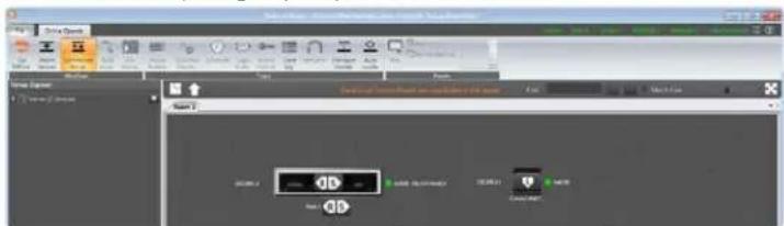
text_image
Screenshot of a software interface showing a media player with playback controls and file name input.TIP: Press "R" to receive settings from the amp or "S" to send the settings from Audio Architect to the amp. See "Going Online" on page 33 for more information about going online.
- The Contrio controller should now be programmed to control the CDi DriveCore amp. Open the amp's control panel, by double-clicking the CDi DriveCore amp image in the Room window, then verify that the Contrio controller is properly controlling the desired parameters. To make additional changes to the Contrio controller programming, repeat the aforementioned steps.
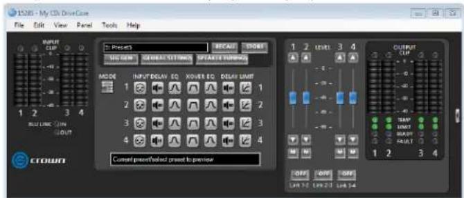
text_image
15285 - My CDI Drive Case File Edit View Panel Tools Help INPUT CLIP Preset RECAST ORDER SUPPORT GAINTEST SETTINGS SPRING SWITCHER ACDE INPUT:DELAY EQ XOVER EQ DELAY LIMIT 1 2 3 4 CURRENT PSEN/SELECT PSEN TO PREVENT OUTPUT CLIP TAWY LINKY BEAVY RUBT 1 2 3 4 OFF OFF OFF LW 32 LW 23 LW 14TIP: Additional controller settings are available in the Contrio Wall Controller Default Control panel (see Figure 62). This panel can be accessed by right-clicking the Contrio Wall Controller image from the Room window and selecting "Show Default Control Panel". See the help file in Audio Architect for additional information on Contrio controller functionality and programming.
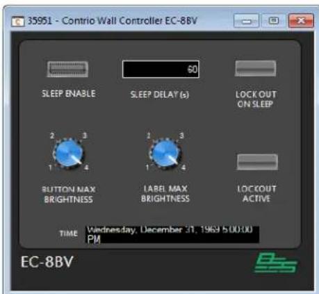
text_image
35951 - Contrio Wall Controller EC-8BV SLEEP ENABLE 60 SLEEP DELAY (s) LOCK OUT ON SLEEP 2 3 1 4 BUTTON MAX BRIGHTNESS 2 3 1 4 LABEL MAX BRIGHTNESS LOCKOUT ACTIVE TIME Wednesday, December 31, 1969 5:00:00 PM EC-8BVFigure 62: Contrio Controller Default Control panel
Saving & Opening Audio Architect Venue Files
When finished programming HARMAN devices in Audio Architect, it is good practice to save the entire venue as a "Venue" file. This will save all Audio Architect configuration changes and the programming and settings for all devices in the current venue configuration to a single file for backup and recall.
To save a Venue file in Audio Architect:
- In the upper left-hand corner of the Main Audio Architect window, select the File tab.
- Select "Save" or "Save As" from the menu.
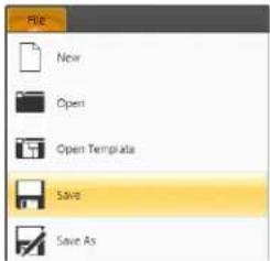
text_image
File New Open Open Templates Save Save As- Select the desired location on the hard drive and name the file. Click the Save button.

text_image
Save As Computer Windows 7 (C:) Users Mike Desktop CDI DriveCore Backup Organize New Folder Desktop Downloads Recent Files Libraries Documents Music Pictures Video Computer Windows 7 (C:) CD Drive (D:) Vdc SCL Server (S) Manager File name: CDI DriveCore Backup Save as type: Audio Architect Version Save CancelTo open a Venue file in Audio Architect:
- In the upper left-hand corner of the Main Audio Architect window, select the File tab.
- Select "Open" from the menu.
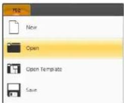
text_image
File New Open Open Template Save- Select the Venue file on the hard drive, then click the Open button.

text_image
Open Computer > Windows 7 (C:) > Users > Mize > Desktop > CDI DriveCore Backup Search CDI DriveCore Backup Organize > New Media Favorites Desktop Downloads Recent Places Libraries Documents Music Pictures Videos Computer Windows 7 (C:) CD Drive (D:) Vnt Desktop (Customs) File name: CDI DriveCore Backup 1 Data modified Type Size CDI DriveCore Backup 1 3/12/2017 & 4/15 PM AUDIOSEARCH SEC... 100 KB Audio Architect Value Open CancelThe Event Log
The Event Log Viewer window (Figure 65) shows events that have occurred within Audio Architect and on HiQnet devices. The log can be used by individual devices to perform certain operations. It can also be used for troubleshooting purposes. The Event Log can be accessed from either the Offline ribbon (Figure 63) or Online ribbon (Figure 64).

text_image
Audio Architect* File Offline Design Add Devices Admin Define Venue Add Devices polarize Route Audio Associate Amplifiers Configure Monitoring Simulate Monitoring Go Online Venue Presets Parameter Presets Scheduler Logic Rules Access Control Event Log NetSetter Firmware Update Auto Update Initiate Audio Update Initiate Audio Initiate Audio Initiate Audio Initiate Audio Initiate Audio Initiate Audio Initiate Audio Initiate Audio Initiate Audio Initiate Audio Initiate Audio Initiate Audio Initiate Audio Initiate Audio Initiate Audio Initiate Audio Initiate Audio Initiate Audio Initiate Audio Initiate Audio Initiate Audio Initiate Audio Initiate Audio Initiate Audio Initiate Audio Initiate Video Initiate Video Initiate Video Initiate Video Initiate Video Initiate Video Initiate Video Initiate Video Initiate Video Initiate Video Initiate Video Initiate Video Initiate Video Initiate Video Initiate Video Initiate Video Initiate Video Initiate Video Initiate Video Initiate Video Initiate Video Initiate Video Initiate Video Initiate Video Initiate Video Initiate Audio Initiate Audio Initiate Audio Initiate Audio Initiate Audio Initiate Audio Initiate Audio Initiate Audio Initiate Audio Initiate Audio Initiate Audio Initiate Audio Initiate Audio Initiate Audio Initiate Audio Initiate Audio Initiate Audio Initiate Audio Initiate Audio Initiate Audio Initiate Audio Initiate Audio Initiate Audio Initiate Audio Initiate Studio Initiate Studio Initiate Studio Initiate Studio Initiate Studio Initiate Studio Initiate Studio Initiate Studio Initiate Studio Initiate Studio Initiate Studio Initiate Studio Initiate Studio Initiate Studio Initiate Studio Initiate Studio Initiate Studio Initiate Studio Initiate Studio Initiate Studio Initiate StudioFigure 63: Accessing the Event Log from the Offline ribbon

text_image
Audio Architect* File Online Operate Go Offline Match Devices Synchronize Venue Route Audio Run Venue Venue Presets Parameter Presets Scheduler Logic Rules Access Control Event Log NetSetter Firmware Update Auto Locate New Add Device Remove DeFigure 64: Accessing the Event Log from the Online ribbon
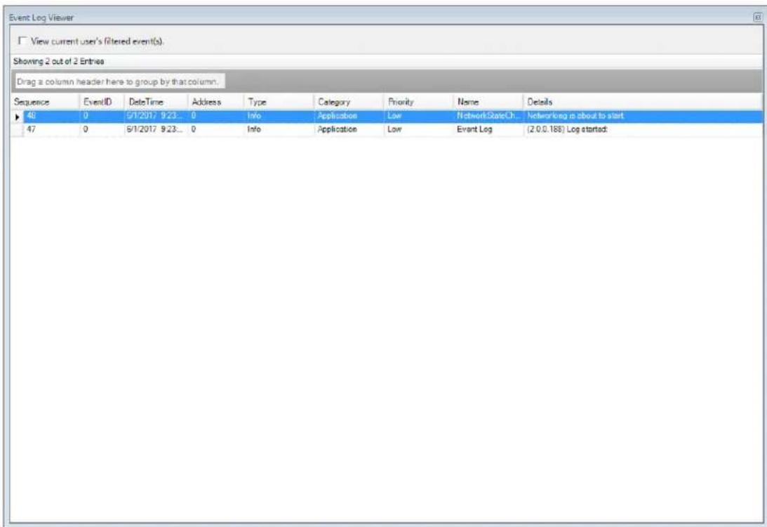
text_image
Event Log Viewer View current user's filtered event(s). Showing 2 out of 2 Entries Drag a column header here to group by that column. Sequence EventID DeleteTime Address Wayte Category Priority None Details 46 0 5/1/2017 9:23... 0Info Application.Low NetworkStateCh... Networking is about to start 47 0 5/1/2017 9:23... 0Info Application.Low Event Log (2.0.0.188) Log started:Figure 65: The Event Log Viewer window
For more information about the Event Log and editing Event Log settings, see the Audio Architect help file.
Application Examples
Dual Mode, Low Z (2Ω, 4Ω, 8Ω, or 16Ω)
Audio Architect software settings are shown in Figure 66. Typical input/output wiring is shown in Figure 67.
INPUTS: Connect the input wires for each channel. See "Wiring Input Connectors" on page 7 for further information on analog input wiring.
If the same input signal is to drive multiple outputs, the input signal can be "Y'ed" by checking the "Y" checkboxes (see Figure 66). See "Configuring Amp Wiring & Bridge Mode" on page 13 for more information.
If using the BLU link input, it is important to understand that BLU link is a digital audio bus and cannot be routed through an Ethernet switch or router. Category 5e or higher cabling must be used for all BLU link connections. To use the built-in BLU link fault protection, the BLU
link output of the last device on the bus must be connected back to the BLU link input of the first device. For additional information on making BLU link connections and using BLU link, see "Using BLU link" on page 59.
OUTPUTS: Maintain proper polarity (+/-) on output connectors. Connect the Channel 1 speaker's positive (+) lead to amplifier Channel 1 positive terminal; repeat for the negative (-) lead. Repeat Channel 2 wiring as for Channel 1, and for any subsequent channel pairs on multichannel models. See "Wiring Output Connectors" on page 7 for additional information on output wiring.
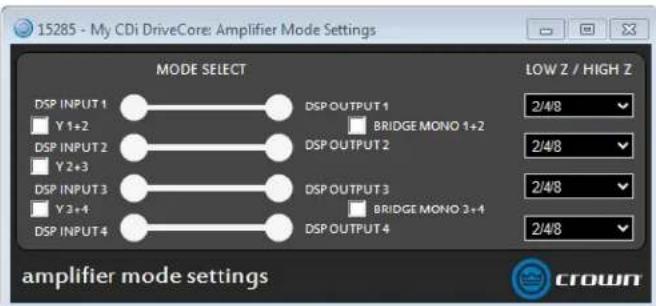
text_image
15285 - My CDi DriveCore: Amplifier Mode Settings MODE SELECT DSP INPUT 1 Y 1+2 DSP INPUT 2 Y 2+3 DSP INPUT 3 Y 3+4 DSP INPUT 4 DSP OUTPUT 1 BRIDGE MONO 1+2 DSP OUTPUT 2 DSP OUTPUT 3 BRIDGE MONO 3+4 DSP OUTPUT 4 LOW Z / HIGH Z 2/4/8 2/4/8 2/4/8 2/4/8 2/4/8 amplifier mode settings CROWNFigure 66: Audio Architect amplifier mode settings

text_image
WARNING - TO BREAK THE RISK OF FIRE OF ELECTRONIC SHOCK. DO NOT EXPIRE THE EQUIPMENT TO MAIN ON VENSING. AVERTISSEMENT - ENGLISH ELECTRUT TRANSFER OR FOR CANEER INSTRUCTIONS. APPROVATE MA THIOPLES JOHN STRIKINQUINATE. APPROVATE SEAL ANLUSING TELE ORCH OUTING. LIFE ON LETER SOLAR/OFFETTE ME LA MARISTETTER POT/RAM/AN. CLASS 2 OUTPUT WIRING PERMITTED. OUTPUT TP OUTPUT WIRING BRIDGE DUAL DUAL 4 3 2 + INPUT MIXERFigure 67: System wiring in Dual mode
NOTE: Always route the input and output wires in separate bundles.
WARNING: Only connect to networks that remain inside the building.
Bridge Mono Mode, Low Z (4Ω, 8Ω, or 16Ω)
Audio Architect software settings are shown in Figure 68. Typical input/output wiring is shown in Figure 69.
INPUTS: If using analog inputs, connect to the odd-numbered input channels (1,3) only. Even-numbered inputs (2,4) are disabled when Bridge Mono mode is active. See "Wiring Input Connectors" on page 7 for further information on analog input wiring.
If using the BLU link input, it is important to understand that BLU link is a digital audio bus and cannot be routed through an Ethernet switch or router. Category 5e or higher cabling must be used for all BLU link connections. To use the built-in BLU link fault protection, the BLU link output of the last device on the bus must be connected back to the BLU link input of the first device. For additional information on making BLU link connections and using BLU link, see "Using BLU link" on page 59.
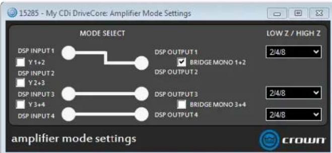
text_image
15285 - My CDi DriveCore: Amplifier Mode Settings MODE SELECT DSP INPUT 1 Y 1+2 DSP INPUT 2 Y 2+3 DSP INPUT 3 Y 3+4 DSP INPUT 4 DSP OUTPUT 1 BRIDGE MONO 1+2 DSP OUTPUT 2 DSP OUTPUT 3 BRIDGE MONO 3+4 DSP OUTPUT 4 LOW Z / HIGH Z 2/4/8 2/4/8 2/4/8 amplifier mode settings crownFigure 68: Audio Architect amplifier mode settings
OUTPUTS: Connect the speaker across the positive (+) terminals of each channel pair. Do not use the negative (-) terminals of the channel pair when the pair is being operated in Bridge Mono mode. See "Wiring Output Connectors" on page 7 for additional information on output wiring. See "Configuring Amp Wiring & Bridge Mode" on page 13 for information on configuring an output pair for bridge mono operation.
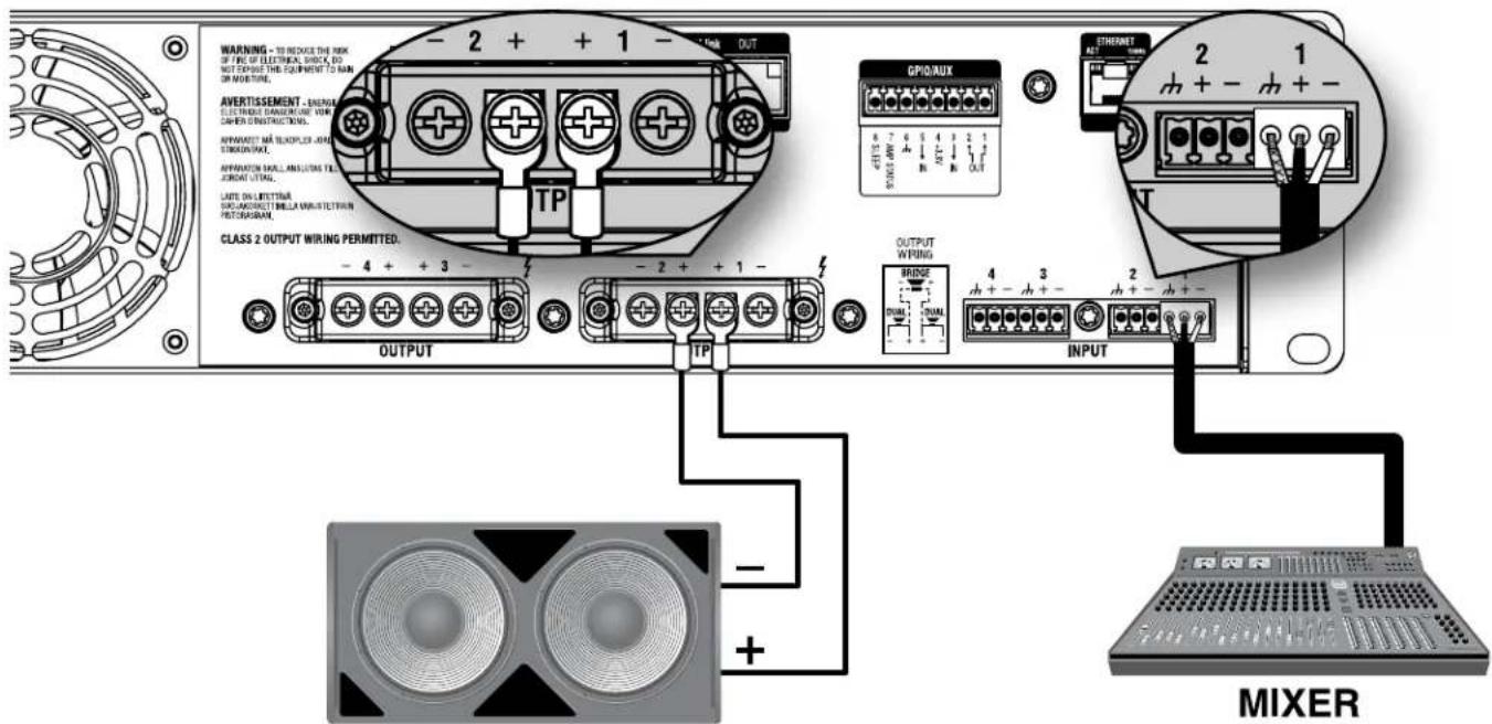
text_image
WARNING - TO REDUCE THE RISK OF PRC OF ELECTRICAL SHOCK DO NOT EXPOSED THE EQUIPMENT TO RAIN OR MOUNTING. AVERTISSEMENT - ENERIAL ELECTRICAL TRANSMISSION VIR CLOTHING INSTRUCTIONS. HYPERATT M2 TELEPHONE 400 STRAWOUT. AFFORDATION WORK ANLICATING TE ORDER OUTING. LATE ON LITERITAR SUSANDRECT BELLAMANISTETRIAN PROMESHAN. CLASS 2 OUTPUT WIRING PERMITTED. OUTPUT TP - 4 + + 3 - - 2 + + 1 - OUTPUT WIPING BRIDGE 4 3 2 + PWM PWM INPUT MIXERFigure 69: System wiring in Bridge Mono mode
NOTE: Always route the input and output wires in separate bundles.
WARNING: Only connect to networks that remain inside the building.
Dual Mode, High Z (70Vrms/100Vrms)
Audio Architect software settings are shown in Figure 70. Typical input/output wiring is shown in Figure 71.
INPUTS: Connect the input wires for each channel. See "Wiring Input Connectors" on page 7 for further information on analog input wiring.
If the same input signal is to drive multiple outputs, the input signal can be "Y'ed" by checking the "Y" checkboxes (see Figure 70). See "Configuring Amp Wiring & Bridge Mode" on page 13 for more information.
If using the BLU link input, it is important to understand that BLU link is a digital audio bus and cannot be routed through an Ethernet switch or router. Category 5e or higher cabling must be used for all BLU link connections. To use the built-in BLU link fault protection, the BLU link output of the last device on the bus must be connected back to the BLU link input of the first device. For additional information on making BLU link connections and using BLU link, see "Using BLU link" on page 59.
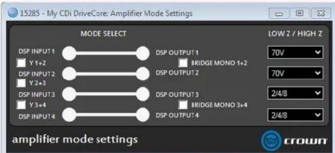
text_image
15285 - My CDi DriveCore: Amplifier Mode Settings MODE SELECT DSP INPUT 1 Y 1+2 DSP INPUT 2 Y 2+3 DSP INPUT 3 Y 3+4 DSP INPUT 4 DSP OUTPUT 1 BRIDGE MONO 1+2 DSP OUTPUT 2 DSP OUTPUT 3 BRIDGE MONO 3+4 DSP OUTPUT 4 LOW Z / HIGH Z 70V 70V 2/4/8 2/4/8 amplifier mode settings crownFigure 70: Audio Architect amplifier mode settings
OUTPUTS: Maintain proper polarity (+/-) on output connectors. Connect the Channel 1 speaker's positive (+) lead to amplifier Channel 1 positive terminal; repeat for the negative (-) lead. Repeat Channel 2 wiring as for Channel 1, and for any subsequent channel pairs on multichannel models. See "Wiring Output Connectors" on page 7 for additional information on output wiring.
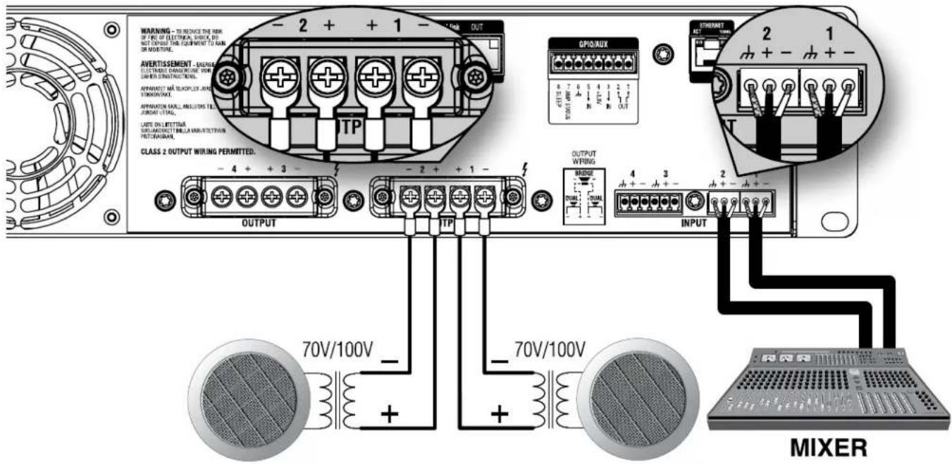
text_image
WARNING - TO REDUCE THE RISK OF FING OF ELECTRICAL SWITCH DO NOT EXPOSED THE EQUIPMENT TO ANN OR NOUSITIME. AVERTISSEMENT - ENGLISH ELECTRAPH TRANSITION WORK ORDER INSTRUCTIONS. APPROVATE ME LEQUIPLER JOHN STICKIN/QUART. APPROVATE SKILL ANLICUM TELE JOURNAL OUTG. LATE ON LITERIA SULFANGSICIT PER LA MINISTETRAN PROGRAHAM. CLASS 2 OUTPUT WIRING PERMITTED. OUTPUT - 4 + + 3 - - 2 + + 1 - OUTPUT WIRING BRIDGE INAM INAM INPUT 70V/100V - 70V/100V - MIXERFigure 71: System wiring for 70Vrms/100Vrms operation
NOTE: A 35Hz high-pass filter is automatically set when an output channel is configured for High Z operation.
NOTE: Each output channel can be independently configured for High Z or Low Z operation. See "Configuring Outputs for Low Z/High Z Operation" on page 40 for more information.
NOTE: Always route the input and output wires in separate bundles.
WARNING: Only connect to networks that remain inside the building.
Bridge Mono Mode, High Z (140Vrms/200Vrms)
Audio Architect software settings are shown in Figure 72. Typical input/output wiring is shown in Figure 73.
INPUTS: If using analog inputs, connect to the odd-numbered input channels (1,3) only. Even-numbered inputs (2,4) are disabled when Bridge Mono mode is active. See "Wiring Input Connectors" on page 7 for further information on analog input wiring.
If using the BLU link input, it is important to understand that BLU link is a digital audio bus and cannot be routed through an Ethernet switch or router. Category 5e or higher cabling must be used for all BLU link connections. To use the built-in BLU link fault protection, the BLU link output of the last device on the bus must be connected back to the BLU link input of the first device. For additional information on making BLU link connections and using BLU link, see "Using BLU link" on page 59.
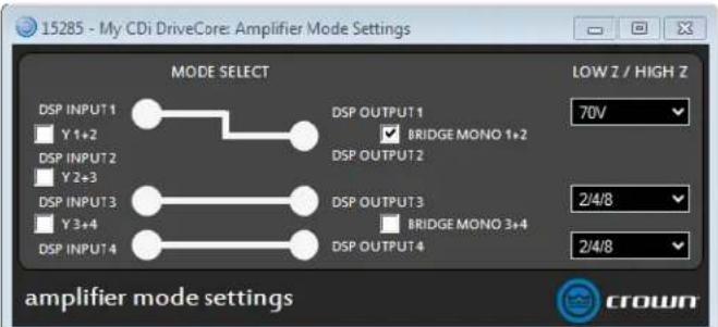
text_image
15285 - My CDi DriveCore: Amplifier Mode Settings MODE SELECT DSP INPUT1 Y 1+2 DSP INPUT2 Y 2+3 DSP INPUT3 Y 3+4 DSP INPUT4 DSP OUTPUT1 BRIDGE MONO 1+2 DSP OUTPUT2 DSP OUTPUT3 BRIDGE MONO 3+4 DSP OUTPUT4 LOW Z / HIGH Z 70V 2/4/8 2/4/8 amplifier mode settings crownFigure 72: Audio Architect amplifier mode settings
OUTPUTS: Connect the speaker across the positive (+) terminals of each channel pair. Do not use the negative (-) terminals of the channel pair when the pair is being operated in Bridge Mono mode. See "Wiring Output Connectors" on page 7 for additional information on output wiring. See "Configuring Amp Wiring & Bridge Mode" on page 13 for information on configuring an output pair for bridge mono operation. See "Configuring Output Modes" on page 15 for information on configuring an output for High Z operation.
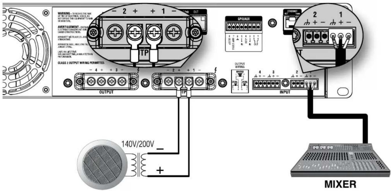
text_image
WARNING - TO REACHS THE RISK UP LINE OF ELECTRICAL SWITCH DO NOT EXPOSED THIS EQUIPMENT TO RUN OR NOVATION. AVERTISSEMENT - ENTER ELECTRIC TANGENTING WORK CAMER INSTRUCTIONS. APPRODUIT ME TRAPLES AND STRAWBUT. APPRODUIT SCAUL ANLICUS TEA JUNAN OUTG. LATE ON LITTING MILK-AGGATET MELLA MINUSTETRIAN POT/RAMAN. CLASS 2 OUTPUT WIRING PERMITTED. OUTPUT TP -4 + + 3 - -2 + + 1 - OUTPUT WIRING BRIDGE 4 3 2 - DUM DUM DUM INPUT 140V/200V - + MIXERFigure 73: System wiring for 140Vrms/200Vrms operation
NOTE: A 35Hz filter is automatically set when an output channel is configured for High Z operation.
NOTE: Each output channel can be independently configured for High Z or Low Z operation. See "Configuring Outputs for Low Z/High Z Operation" on page 40 for more information.
NOTE: Always route the input and output wires in separate bundles.
WARNING: Only connect to networks that remain inside the building.
Using BLU link
BLU link is a digital audio bus found on the BLU link CDi DriveCore amplifier models. BLU link devices are connected using standard Category 5e or higher cabling. This minimizes cable connections and reduces the amount of cable required, hence, cable cost. BLU link connections carry up to 256 channels of high-resolution digital audio at 48kHz, or 128 channels at 96kHz, both at 24-bit.
BLU link Specifications
- Based on Gigabit Ethernet technology
- Up to 100m over CAT5e cable between each point (>100m using fibre converters)
• 256 channels at 48kHz
• 128 channels at 96kHz
• 24-bit audio resolution - Bus-like architecture — audio transmitted on a channel is available at all other devices on the bus automatically
- Wired in a loop for redundancy — recovers from a single cable break
- Up to 60 BLU link nodes (devices) can exist in a single BLU link system
BLU link Latency
| Path Total Latency (for selected path) | |
| Analog Input to Amplifier Output 1.78ms | |
| BLU link Input to BLU link Output (48kHz) 4 | 47ms |
| BLU link Input to BLU link Output (96kHz) 3 | 57ms |
NOTE: Latency through the BLU link/analog mixed paths will be greater than the "Analog Input to Amplifier Output" path but less than the "BLU link Input to BLU link Output" paths.
Making BLU link Connections
On the rear panel of BLU link devices there are two BLU link ports: a BLU link input port and a BLU link output port. Devices are connected together by wiring the output port of the first device to the input port of the next, then repeating for each BLU link device on the bus. If redundancy is required, the last BLU link device on the bus should be connected back to the first. This allows audio to still pass through the BLU link ring when a single BLU link cable is compromised or disconnected.
If ferrites were included with the amplifier, they should be attached to the BLU link cables at the back of the amplifier as shown in Figure 74. If no ferrites were included, they are not required.
NOTE: Only connect BLU link ports to other BLU link ports. Connecting BLU link ports to networking peripherals, such as an Ethernet switch or router, will not work.
See "Assigning Input Sources" on page 14 for information on assigning BLU link input channels.
See "Configuring BLU link Settings" on page 22 for information on assigning BLU link output channels and configuring the BLU link sample rate.
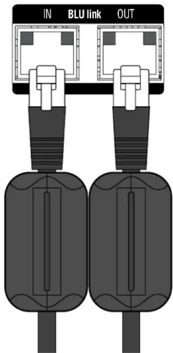
text_image
IN BLU link OUTFigure 74: Ferrites installed on BLU link cables
BLU link Port LED Indicators
Each BLU link port has LEDs that indicate the following:
Both Yellow LEDs On
This indicates the device is the BLU link master (meaning it's providing the clock for the entire BLU link system).
The green LEDs light to indicate the port has established a link with the BLU link bus. If there are no cables connected, the green LEDs will not light.
One Yellow LED On
This indicates the device is slaved to the BLU link clock received from the connected device.
The green LEDs light to indicate the port has established a link with the BLU link bus.
No Yellow LEDs On
This indicates the device is not receiving BLU link clock and will not pass audio. This either indicates the IN and OUT ports are swapped (an OUT port is connected to an OUT port and an IN port is connected to an IN port), or there is a mismatch between the BLU link sample rates of the amplifier and the connected device(s).
See "Configuring BLU link Settings" on page 22 for information on configuring the amplifier's BLU link sample rate.
The green LEDs light to indicate the port has established a link with the BLU link bus.
WARNING: Only connect to networks that remain inside the building.
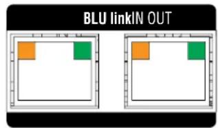
text_image
BLU linkIN OUT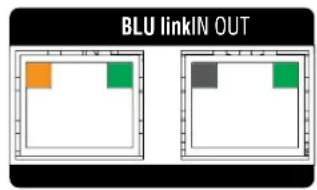
text_image
BLU linkIN OUT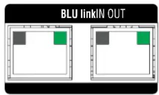
text_image
BLU linkIN OUTMastership
The BLU link bus requires one device on the bus to act as master. The master will provide the clock for all other devices on the bus. This means that the whole bus is synchronised to a single audio clock.
NOTE: The BLU link sample rate for all device's on a BLU link bus must be configured to match. By default, the CDi DriveCore amps are configured with the BLU link sample rate set to 96kHz.
In certain cases, it is possible to incorporate devices of more than one Ethernet transport type (i.e., AVB, CobraNet™, or Dante™) connected within the same BLU link system. In other words, if you're careful, you can design a Harman system which actually includes two or more transports. For example, it's possible for a Harman system to have CobraNet audio being converted to BLU link audio (BLU-800 and BLU-320 both have the ability to "bridge" CobraNet to/from BLU link), which is then converted to Dante audio (BLU-806 and BLU-326 both have the ability to "bridge" BLU link to/from Dante). It all depends on a given transport's ability to "slave" (AKA "re-clock") to a clock being generated by a separate transport.
Which transports support "slaving" to the clock of another transport?
| Transport Supports Slaving to Another Transport | |
| AVB No | |
| BLU link Yes | |
| CobraNet No | |
| Dante Yes | |
The previous table has critical implications on system design when combining two or more transports. Any system based on Soundweb London (including Architectural Media Systems) supports the multi-transport combinations shown in the following table.
| Combined Transports Clock Master | |
| BLU link + AVB AVB provides the clock | |
| BLU link + CobraNet CobraNet provides the clock | |
| BLU link + Dante Either BLU link or Dante provides the clock | |
| BLU link + Dante + AVB AVB provides the clock |
Any multi-transport combination NOT specifically listed in the previous table is not allowed in Soundweb London systems (without being forced to use analog interconnects between transports). For example, BLU link + AVB + CobraNet is NOT allowed, because the AVB and CobraNet networks would each be synced to different clocks — their own.
Mastership is negotiated between all devices on the BLU link bus, and any change to the bus will trigger the negotiation to restart. The following rules determine which device on the BLU link bus will become clock master:
- If there is only one BLU link device connected to CobraNet/AVB then that device is master.
- If there are multiple BLU link devices connected to CobraNet/AVB, then they compare master priorities.
- If there are multiple BLU link devices on CobraNet/AVB with the same highest priority, then they use MAC address to decide which is master.
- If there are no BLU link devices connected to CobraNet/AVB, then they first compare master priorities. Next, if the priorities are the same, they compare MAC addresses.
Fault Tolerance
When the last BLU link device in a system is connected back to the first, the BLU link bus is capable of a degree of fault tolerance since each device receives the same audio from two other devices. If a single cable connection is broken, the devices which are no longer connected will detect the cable break: one device will detect that its BLU link in port is disconnected and the other will detect that its out port is disconnected. The devices will then reroute the audio so that it can again pass through the bus.
NOTE: When the cable is broken, the audio will take longer to reach its destination. This added delay is not compensated for in any way, but is a side-effect of the way the fault tolerance system functions.
BLU link Status
The BLU link Status menu displays BLU link information, which can be used to verify and troubleshoot the amplifier's BLU link connections and settings.
To view BLU link status:
- From the Home screen, press the MENU button.
- Select the "BLU link" option from the menu using the ENCODER.
- Select the "BLU link Status" option from the menu.
- Use the ENCODER to scroll the menu.

text_image
BLU link IP: 192.168.0.36 BLU Link STATUS 1. CURRENT SAMPLE RATE 96 kHz 2. MASTER PRIORITY 0 3. INPUT PORT STATUS Connected 4. OUTPUT PORT STATUS Connected 5. INPUT ERROR COUNT 0Figure 75: BLU link Status menu
Available options:
- Current Sample Rate
Displays the current BLU link sample rate setting of the amplifier. This can be set in the BLU link Settings menu.
• Master Priority Displays the current BLU link Master Priority setting of the amplifier.
- Input Port Status
Indicates whether or not an valid BLU link connection has been made to the BLU link input port. Under normal operating conditions, "Connected" will be displayed. If no valid connection is made to the BLU link bus, "Not Connected" will be displayed. If "Error" is displayed, this indicates the BLU link input and output cables may be swapped, or the BLU link sample rate of the amp does not match the sample rate of the connected BLU link bus.
- Output Port Status
Indicates whether or not an valid BLU link connection has been made to the BLU link output port. Under normal operating conditions, "Connected" will be displayed. If no valid connection is made to the BLU link bus, "Not Connected" will be displayed. If "Error" is displayed, this indicates the BLU link input and output cables may be swapped, or the BLU link sample rate of the amp does not match the sample rate of the connected BLU link bus.
- Input Error Count Displays the number of BLU link input data errors that have occurred.
- Input Corrected Count Displays the number of BLU link input data errors corrected.
- Input Error Reset Press the ENCODER with this option selected to reset the Input Error Count and Input Corrected Count back to 0.
- Output Error Count Displays the number of BLU link output data errors that have occurred.
- Output Corrected Count Displays the number of BLU link output data errors corrected.
- Output Error Reset Press the ENCODER with this option selected to reset the Output Error Count and Output Corrected Count back to 0.
- Version Displays the current BLU link firmware version.
• MAC Address Displays the MAC address of the amplifier.
- Master MAC Address Displays the MAC address of the device providing the master clock for the entire BLU link bus.
Device Presets
Device presets allow configuration, DSP, channel assignment, gains, as well as other settings to be stored for later recall. A device preset can be used to configure the amp for a specific application and speaker model. For example, you might use one device preset that optimizes the amp's DSP for a JBL bi-amplified speaker setting. Or, you might use a device preset that sets up the DSP for a stereo pair of loudspeakers of your choice. Subtle changes can also be made between device presets, such as a change of input channel assignments. Device presets can be stored within the amplifier or backed up to a PC using Audio Architect.
Preset 1 is the factory default device preset and cannot be overwritten. It sets up the amplifier for pass-thru operation with no DSP features enabled. Presets 2-20 are user device presets and can be overwritten.
The following bullets outline which settings are stored to device presets and which are not:
Settings Stored to Device Presets
- DSP Settings
• Signal Generator Settings - Levels
- Mutes
- Internal Amp Wiring (Y'ed inputs, dual-mono/bridge mode)
- Input Source Assignments (analog and BLU link)
- Amp Gain Mode
• Output Mode (Low Z, High Z) - BLU link Output Assignments
• GPIO Manual Aux Output Setting (available in Audio Architect)
Settings NOT Stored to Device Presets
• Front Panel Lighting/Display Options
- Front Panel Security
• Network Settings
- BLU link Sample Rate
- BLU link Mastership Priority
Saving Device Presets
To save the current settings as a device preset from the front panel:
- From the Home screen, press the MENU button.
- Select the "Configure Amplifier" option from the menu using the ENCODER.
- Select the "Save Preset" option.
- Select "YES".
- Select the Preset ID to which you wish to save the preset.
- An on-screen keyboard will appear, allowing you to name the preset. Select "Done" when done.
- Press the ENCODER to save the preset.
NOTE: Any unsaved settings will be retained in the amplifier after a power cycle. However, settings should be saved before loading another device preset if you wish to recall them at a later time, otherwise settings will be lost.
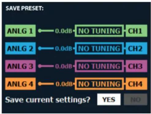
flowchart
graph LR
    A["ANLG 1"] -->|0.0dB| B["NO TUNING"]
    C["ANLG 2"] -->|0.0dB| D["NO TUNING"]
    E["ANLG 3"] -->|0.0dB| F["NO TUNING"]
    G["ANLG 4"] -->|0.0dB| H["NO TUNING"]
    B --> I["CH1"]
    D --> J["CH2"]
    F --> K["CH3"]
    H --> L["CH4"]
    style A fill:#99ccff,stroke:#333
    style C fill:#99ccff,stroke:#333
    style E fill:#99ccff,stroke:#333
    style G fill:#99ccff,stroke:#333
    style B fill:#66ccff,stroke:#333
    style D fill:#66ccff,stroke:#333
    style F fill:#66ccff,stroke:#333
    style H fill:#66ccff,stroke:#333
    note right of A: Save preset?
    note right of G: Save current settings? YES NO
Figure 76: Saving a device preset
For information on saving device presets in Audio Architect, see "Main CDi DriveCore Control Panel" on page 34.
Loading Device Presets
To load a device preset from the front panel:
- From the Home screen, press the MENU button.
- Select the "Configure Amplifier" option from the menu using the ENCODER.
- Select the "Load Preset" option.
- Use the ENCODER to navigate presets using the on-screen "PREV" and "NEXT" buttons. As each preset is selected, the preset number, name, and configuration will be displayed on-screen.
- Once the desired preset has been selected, use the ENCODER to select "LOAD".
For information on loading device presets in Audio Architect, see "Main CDi DriveCore Control Panel" on page 34.
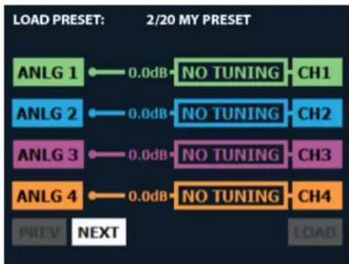
flowchart
graph LR
    A["ANLG 1"] -->|0.0dB| B["NO TUNING"]
    C["ANLG 2"] -->|0.0dB| D["NO TUNING"]
    E["ANLG 3"] -->|0.0dB| F["NO TUNING"]
    G["ANLG 4"] -->|0.0dB| H["NO TUNING"]
    I["PREV NEXT"] --> J["LOAD"]
    style A fill:#99ccff,stroke:#333
    style C fill:#99ccff,stroke:#333
    style E fill:#99ccff,stroke:#333
    style G fill:#99ccff,stroke:#333
    style I fill:#ffcc99,stroke:#333
Figure 77: Loading a device preset
System Settings
Lighting/Display Options
These options can be used to turn off the front panel LCD and LEDs, and change the on-screen color scheme.
To edit lighting options:
- From the Home screen, press the MENU button.
- Select the "System Settings" option from the menu using the ENCODER.
- Select "Lighting/Display Options" from the menu.
- Select the desired options, making selections with the ENCODER.
- When done, select "Done" at the bottom of the screen.
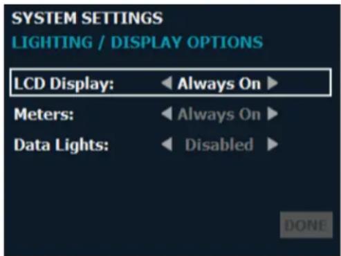
text_image
SYSTEM SETTINGS LIGHTING / DISPLAY OPTIONS LCD Display: ← Always On ► Meters: ← Always On ► Data Lights: ← Disabled ► DONEFigure 78: Lighting Options menu
Available options/parameters:
• LCD Display (Always On, 30 sec, 5 min, 30 min)
This option allows the LCD to go to sleep after a specified time period of inactivity. Once asleep, any button press will wake up the LCD.
NOTE: In the event of an error, such as a shorted output or thermal error, the LCD screen will turn on and indicate the issue, regardless of the selected lighting options.
- Meters (Always On, 30 sec, 5 min, 30 min)
This option allows the signal level meters to turn off after a specified time period of inactivity.
NOTE: The LED meters will still show clip indication when LEDs are turned off.
• Data Lights (Disabled, Enabled)
This option allows the DATA LED to be turned off or on.
Security/Front Panel Lockout
The Front Panel Lockout feature allows front panel functionality to be locked out to prevent unauthorized tampering of the amplifier's settings. This feature can be enabled from the Security screen (see Figure 79) or by simply pressing and holding the CH1 SELECT button and ENCODER simultaneously for 2 seconds from the Home screen.
To enable the Front Panel Lockout:
- From the Home screen, press the MENU button.
- Select the "System Settings" option from the menu using the ENCODER.
- Select "Security" from the menu.
- Enable the "Front Panel Lockout Enable" option using the ENCODER.
NOTE: You can also enable the "Front Panel Lockout Delay" option which will cause the front panel to automatically re-lock after approximately 30 seconds each time the front panel is unlocked.
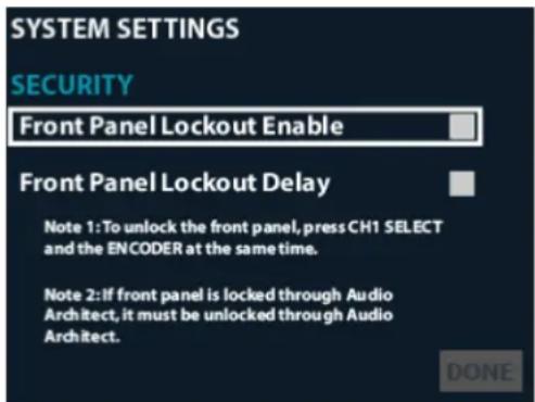
text_image
SYSTEM SETTINGS SECURITY Front Panel Lockout Enable Front Panel Lockout Delay Note 1: To unlock the front panel, press CH1 SELECT and the ENCODER at the same time. Note 2: If front panel is locked through Audio Architect, it must be unlocked through Audio Architect. DONEFigure 79: Security screen
- Using the ENCODER, select "Done" at the bottom of the screen. If the "Front Panel Lockout Delay" option was not enabled, a prompt will immediately appear on the LCD to indicate that the front panel is now locked. If the "Front Panel Lockout Delay" option was enabled, the front panel will be locked after approximately 30 seconds.
NOTE: The POWER button will still function when the Front Panel Lockout feature is enabled.
To disable the Front Panel Lockout:
- Simultaneously press and hold the CH1 SELECT button and ENCODER for 2 seconds. A prompt will appear on the LCD to indicate the front panel is now unlocked. Note that the front panel will only remain unlocked for approximately 30 seconds if the "Front Panel Lockout Delay" option has been enabled.
- From the Home screen, press the MENU button.
- Select the "System Settings" option from the menu using the ENCODER.
- Select "Security" from the menu.
- Disable the "Front Panel Lockout Enable" option using the ENCODER.
- Using the ENCODER, select "Done" at the bottom of the screen.
TIP: The front panel can also be locked from the Global Settings panel in Audio Architect. Note that if the front panel has been locked from Audio Architect, the above procedure will not work for unlocking it and it must be unlocked using Audio Architect. See "Amplifier Information" on page 35 for information on locking/unlocking the front panel from Audio Architect.
Amp Gain Mode
The Amp Gain setting sets how much gain will be applied to the signal within the amplifier (from input to output) and can be set from the Amp Gain Mode screen.
To edit the Amp Gain setting:
- From the Home screen, press the MENU button.
- Select the "System Settings" option from the menu using the ENCODER.
- Select the "Amp Gain" option from the menu.
- Press the ENCODER to edit the Amp Gain setting.
- Turn the ENCODER to select the desired Amp Gain setting.
- When done, press the ENCODER to make the selection then select "Done" at the bottom of the screen.
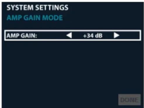
text_image
SYSTEM SETTINGS AMP GAIN MODE AMP GAIN: ← +34 dB ► DONEFigure 80: Amp Gain Mode screen
Available options:
- Amp Gain (+37dB, +34dB, +26dB)
Sets how much gain will be applied to the signal within the amplifier (from input to output).
Power Modes
The APD and ACD power modes allow the CDi DriveCore amplifiers to conserve power consumption during periods of inactivity. The APD and ACD features are enabled by default from the factory.
To edit power mode settings:
- From the Home screen, press the MENU button.
- Select the "System Settings" option from the menu using the ENCODER.
- Select the "Power Modes" option from the menu.
- Turn and press the ENCODER to select the desired settings.
- When done, select "Done" at the bottom of the screen.
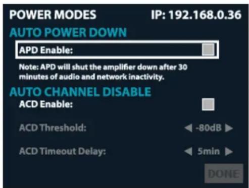
text_image
POWER MODES IP: 192.168.0.36 AUTO POWER DOWN APD Enable: Note: APD will shut the amplifier down after 30 minutes of audio and network inactivity. AUTO CHANNEL DISABLE ACD Enable: ACD Threshold: -80dB ACD Timeout Delay: 5min DONEFigure 81: Power Modes screen
Available options:
- APD Enable
Checking this checkbox enables the APD feature. - ACD Enable
Checking this checkbox enables the ACD feature.
See "Amplifier Information" on page 35 for information on editing power mode settings in Audio Architect.
See "Power Saving Modes" on page 71 for additional information on the APD and ACD features.
Amplifier Diagnostics
The Diagnostics screen provides a read-only list of amplifier information (see Figure 82).
To enter the Diagnostics screen:
- From the Home screen, press and hold the ENCODER for \~2 seconds to navigate directly to the Diagnostics screen. Alternatively, you can press the MENU button and follow the proceeding steps.
- Select the "System Settings" option from the menu using the ENCODER.
- Select the "Diagnostics" option.
- Use the ENCODER to scroll the menu.
Information displayed:
- Firmware Version
- AC Input Voltage
• Power Supply Temperature - Channel 1 Temperature
- Channel 2 Temperature
- Channel 3* Temperature
- Channel 4* Temperature
- Serial Number
- Manufactured Date
*Channel 3 and 4 options available in 4-channel CDi DriveCore models only.
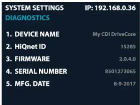
text_image
SYSTEM SETTINGS IP: 192.168.0.36 DIAGNOSTICS 1. DEVICE NAME My CDi DriveCore 2. HiQnet ID 15285 3. FIRMWARE 2.0.4.0 4. SERIAL NUMBER 8501273065 5. MFG. DATE 8-9-2017Figure 82: Diagnostics screen
Using the GPIO Control Port
CDi DriveCore amplifiers come with a 2-in, 2-out General Purpose In/Out (GPIO) control port in the form of a block connector. The Control port has multiple uses which include fault status reporting, device preset selection, output muting, and more. Control ports are configured using the Audio Architect software.
GPIO Pinout, Specification, Use, & Configuration
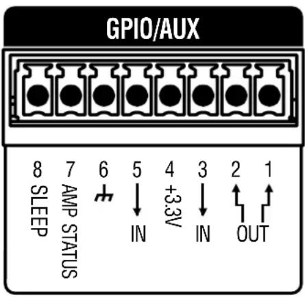
text_image
GPIO/AUX 8 7 6 5 4 3 2 1 SLEEP AMP STATUS IN +3.3V IN OUTPIN 1 (Output 1): 0VDC to +3.3VDC output. Output impedance = 1KΩ pullup to +3.3V. This pin is used for fault reporting. If a fault occurs in the amplifier, this pin will change from a low/false state to a high/true state. Polarity can be inverted when reversed functionality is required. See "Amplifier Information" on page 35 for information on inverting this output.
PIN 2 (Output 2): 0VDC to +3.3VDC output. Output impedance = 1KΩ pullup to +3.3V. This pin is used by Audio Architect and compatible HiQnet wall controllers for generic output control functions. The functionality of this output is tied to the Manual Aux Output button in the Global Settings panel in Audio Architect. See "Amplifier Information" on page 35 for more information on the Manual Aux Output button.
PIN 3 (Input 1): OVDC to +3.3VDC input. Logic = TTL thresholds. Analog = full scale 0-3.3V. Input impedance >20KΩ. This pin is used to trigger input mutes. By default, a high/true state at the input will trigger the mutes. Polarity can be inverted when reversed functionality is required. Which input channels are muted can be programmed from the Global Settings panel in Audio Architect. See "Amplifier Information" on page 35 for more information on configuring this input.
PIN 4 (3.3V): +3.3VDC output. LIMIT = 30mA. Output impedance = 100Ω to +3.3V. This pin provides the power source to drive the GPIO inputs. For example, a simple switch between this pin and pin 3 (Input 1) will mute/un-mute the designated input channels (a closed switch connects the 3.3V for high/true condition, an open switch allows the pin to float low for false condition).
PIN 5 (Input 2): OVDC to +3.3VDC input. Logic = TTL thresholds. Analog = full scale 0-3.3V. Input impedance > 20KΩ. This pin is used to trigger preset changes between two stored presets depending on high/low state. Which presets are triggered can be configured from the Global Settings panel in Audio Architect. See "Amplifier Information" on page 35 for more information on configuring this input port.
PIN 6 (GND): Provides the ground potential for GPIO outputs and the AUX port.
Using the AUX Port
The AUX port can be used for basic monitoring of the amplifier and for remote standby (sleep). The port is shared with the GPIO using an 8-pin block connector, with pin 6 used as ground.
Sleep
The amplifier can be put to sleep by connecting pins 6 and 8 together on the AUX port. When applying this connection, the amplifier will shut down and remain asleep until the connection between pins 6 and 8 is opened. When the connection between pins 6 and 8 is open, the amplifier will revert to its last configuration and begin to output audio within \~15 seconds. Network communication will be re-established once the network interface card boots. While the amplifier is asleep, the front panel POWER button is disabled and, if pressed, the blue power indicator will blink briefly to indicate the device is asleep.
Sleep Closed
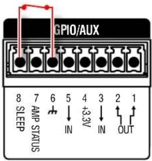
text_image
GPIO/AUX 8 7 6 5 4 3 2 1 SLEEP AMP STATUS IN +3.3V IN OUTSleep Open

text_image
GPIO/AUX 8 7 6 5 4 3 2 1 SLEEP AMP STATUS IN IN OUTAmp Status
Amp Status can be used for basic monitoring of the amplifier. Monitoring of the amplifier can determine if the amplifier is operating within optimal parameters, or if the amplifier has been shut off or is in fault. Between pins 6 and 7, there will be either a +5VDC potential or a 2Hz square wave (heart beat). This option can be set from the Global Settings panel in Audio Architect, see "Amplifier Information" on page 35.
Amp Status Closed
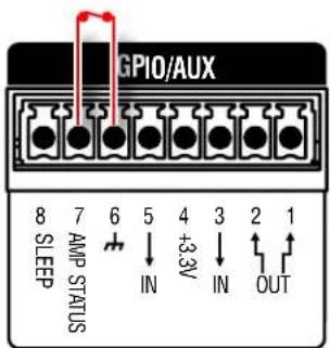
text_image
GPIO/AUX 8 7 6 5 4 3 2 1 SLEEP AMP STATUS IN +3.3V IN OUTAmp Status Open
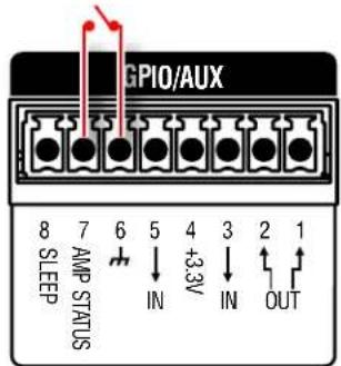
text_image
GPIO/AUX 8 7 6 5 4 3 2 1 SLEEP AMP STATUS IN +3.3V IN OUTPower Saving Modes
The ACD and APD power saving modes allow the CDi DriveCore amplifiers to conserve power consumption during periods of inactivity. The ACD and APD features are enabled by default from the factory.
Auto Channel Disable (ACD)
The CDi DriveCore's individual amplifier channels will automatically disable after a period of channel inactivity. This will occur 30 minutes after audio is no longer present at the output of the DSP for a given channel. A channel will re-enable within 0.5 seconds of audio being sensed at the output of the DSP unless the amplifier has entered Auto Power Down (APD) mode.
NOTE: The ACD feature can be disabled or adjusted from the front panel (see "Power Modes" on page 67) or from Audio Artchitect (see "Amplifier Information" on page 35). Note that ACD will be re-enabled if the amplifier is factory reset or the default preset is loaded.
Auto Power Down (APD)
The APD feature allows a CDi DriveCore amplifier to automatically power down after a period of audio and network inactivity. The amplifier will enter APD mode 30 minutes after all of the following conditions are met:
- There is no signal level detected above approximately -50 dBu at any of the analog inputs
- There is no activity detected on the BLU link network (BLU link CDi DriveCore models only)
• The signal generator is not active
• There is no activity detected on the data network
Once the amplifier has entered APD mode, it will exit APD mode if one of the following conditions is met:
- The POWER button is pressed (the sleep pin on the Aux port must also be open (not active))
- Signal level is detected at any of the analog inputs (the sleep pin on the Aux port must also be open (not active))
The amplifier will take approximately 30 seconds to fully recover from APD mode.
NOTE: The APD timer setting is defaulted to 30 minutes from the factory. This timer setting is user adjustable, but it is not available from any preconfigured panels in Audio Architect or from the amplifier's front panel user interface. To access the APD timer setting, the "AmAPDTimeoutSec" SV (located under [0x1]>AM3 in the Venue Explorer tree menu) must be added to a custom panel. Once the desired SV has been added to the custom panel, go online with the amplifier, run the custom panel, then adjust the setting. See the Audio Architect help file for information on using custom panels in Audio Architect. APD can be disabled from the front panel (see "Power Modes" on page 67) or from Audio Architect (see "Amplifier Information" on page 35). Note that APD will be re-enabled if the amplifier is factory reset or the default preset is loaded.
NOTE: 2-channel CDi DriveCore amplifiers manufactured before a certain date are not compatible with the APD feature. For more information, please contact Crown Technical Support.
System Protection
Faults
The amplifier will enter a fault state if it senses an unsafe condition. This protection is for both internal and external faults. In addition, be sure that the load connected to the amplifier is within the 2-16 Ohm limit (4-16 Ohm in Bridge Mono mode). If wiring and load are verified as correct and the fault condition persists, see "Service" on page 88 for servicing information.
The following faults are possible:
| Fault Fault Type Description | ||
| HF Detect Channel Excessive high frequency signal content has been sensed at the output of the amplifier. | ||
| DCLF Channel Excessive DC or low frequency signal content has been sensed at the output of the amplifier. | ||
| Short Circuit Detect Channel A short is detected at the output of the amplifier. | ||
| Thermal Channel/Power Supply | An amp channel and/or the power supply has exceeded the maximum acceptable temperature threshold. | |
| High Voltage Rail Power Supply | The power supply's high voltage rails are no longer within a safe operating range for the amplifier or other components attached. | |
| Low Voltage Rail Power Supply | The power supply's low voltage rails are no longer within a safe operating range for the amplifier or other components attached. | |
| AC Mains Power Supply | The AC mains have reached an unsafe level. | |
Thermal Limit
If the amplifier power supply and/or any channels become too hot for safe operation, a thermal fault will occur. If a channel's temperature reaches 80^ Celsius, a message will appear in the front panel display to indicate the onset of audio compression. The amplifier will continue to run in this state until either the temperature is reduced to a safe operating range, or if the temperature continues to rise, the channel will shut off to protect itself above 100^ Celsius. The amplifier will exit the thermal fault state only when the temperature drops back below the thermal limit.
NOTE: If the thermal limit is exceeded while the front panel LCD is asleep, the display will wake up to indicate that thermal limiting is occurring.
Auto-Insertion High-Pass Filters
A 35Hz, 24dB/Octave Butterworth high-pass filter is inserted automatically when a channel is configured for High Z operation. A 10Hz, 24dB/Octave Butterworth high-pass filter is inserted automatically when a channel is configured for Low Z operation.
AC Under/Over-Voltage Protection
If the AC line voltage drops below 10% or rises above 10% of the nominal operating voltage of the amplifier, the amplifier's power supply will turn off and the blue Power LED will flash. The amplifier will turn back on when the AC line voltage returns to safe operating levels.
Fan-Cooled Chassis
CDi DriveCore Series amplifiers are cooled by quiet, variable-speed fans. Maximum fan noise level of the CDi DriveCore amplifier is 51dBA. The fans will pull air from the front of the amplifier to the rear.
The following fault conditions cause the fan to turn on full speed:
- High frequency fault (excessive high frequency signal content has been sensed at the output of the amplifier)
• Thermal fault (excessive power supply or channel temperature is detected)
NOTE: After a fault, the fan will remain on at full speed until the fault is cleared.
Universal Switching Power Supply
The CDi DriveCore Series amplifiers incorporate a switching power supply designed for extremely high efficiency and high output power. The supply includes Power Factor Correction (PFC) and a Series Resonant Converter (SRC), and accepts AC supply voltages from \~100V to \~240V. Microprocessor-controlled diagnostic and control capabilities both optimize performance and enhance long-term reliability.
Troubleshooting
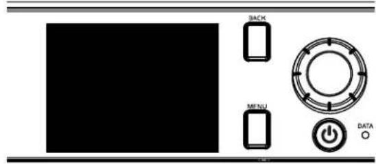
text_image
BACK MENU DATAThe image contains no legible text or symbols. According to Rule 4 (Edge Noise Strategy), since the ground truth is not clearly visible, OCR should not output any character. Therefore, the corrected OCR text is:
[No legible text]
CONDITION: Power indicator and LCD are off.
POSSIBLE REASON
- The amplifier is not plugged in to the power receptacle.
• The amplifier has lost AC Power.
• The power supply fuse has tripped.
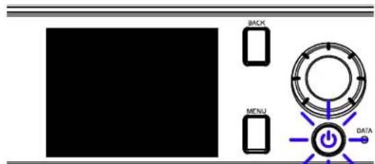
text_image
BACK MENU DATA1964年10月2日
CONDITION: Power indicator is flashing blue indefinitely.
POSSIBLE REASON:
- The AC line voltage has dropped below 10% or has risen above 10% of the nominal line voltage of the power supply. See "System Protection" on page 72 for information on AC under/over voltage protection.
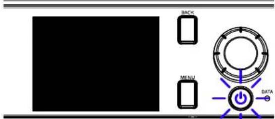
flowchart
graph TD
    A["BACH"] --> B["Central Circle"]
    C["MENU"] --> B
    D["Data"] --> B
    B --> E["Power Supply"]
    style A fill:#000,stroke:#fff,color:#fff
    style C fill:#000,stroke:#fff,color:#fff
    style D fill:#000,stroke:#fff,color:#fff
    style B fill:#fff,stroke:#000,stroke-width:2px
    style E fill:#fff,stroke:#000,stroke-width:2px
1964.2.2017.15.2.2018.15.2.2019.15.2.2020.15.2.2021.15.2.2022.15.2.2023.15.2.2024.15.2.2025.15.2.2026.15.2.2027.15.2.2028.15.2.2029.15.2.2030.15.2.2031.15.2.2032.15.2.2033.15.2.2034.15.2.2035.15.2.2036.15.2.2037.15.2.2038.15.2.2039.15.2.2040.15.2.2041.15.2.2042.15.2.2043.15.2.2044.15.2.2045.15.2.2046.15.2.2047.15.2.2048.15.2.2049.15.2.2050.15.2.2051.15.2.2052.15.2.2053.15.2.2054.15.2.2055.15.2.2056.15.2.2057.15.2.2058.15.2.2059.15.2.2060
CONDITION: When pressing the Power button, power won't turn on and Power indicator flashes blue briefly.
POSSIBLE REASON:
- The amplifier is asleep via the Aux port (contact closure) circuit. See "Using the AUX Port" on page 70 for more information.
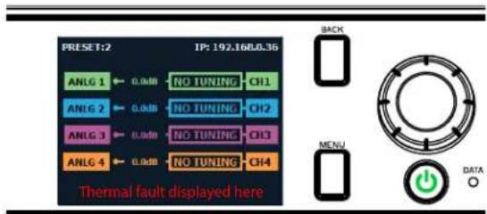
text_image
PRESET:2 TP: 192.1680.35 ANLG 1 ← 0.0dB NO TUNING CH1 ANLG 2 ← 0.0dB NO TUNING CH2 ANLG 3 ← 0.0dB NO TUNING CH3 ANLG 4 ← 0.0dB NO TUNING CH4 Thermal fault displayed here BACK MENU DATACONDITION: Thermal fault is indicated in the display.
POSSIBLE REASON:
- The amplifier is becoming too hot for safe operation. Allow amplifier to cool. Check for loads less than 2Ω and for excessive input levels. Check for proper ventilation and proper output mode (2/4/8Ω, 70V, 100V) setting. See "Proper Cooling" on page 2 for information on rack mounting and cooling. See "System Protection" on page 72 for detailed information on thermal limits. See "Configuring Output Modes" on page 15 for information on configuring the output mode.
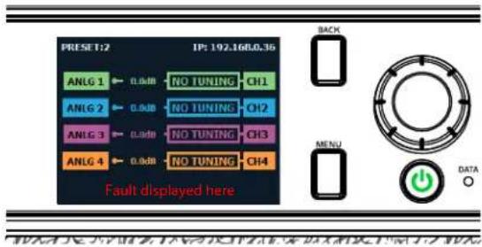
text_image
PRESET:2 IP: 192.160L0.35 ANLG 1 ← 0.0dB NO TUNING CH1 ANLG 2 ← 0.0dB NO TUNING CH2 ANLG 3 ← 0.0dB NO TUNING CH3 ANLG 4 ← 0.0dB NO TUNING CH4 Fault displayed here BACK MENU DATA ○CONDITION: Some other fault is indicated in the display.
POSSIBLE REASON:
- There are a number of conditions that result in a fault error being displayed: the operating temperature exceeds 100°C, excessive high or low frequencies are detected at the output, or an output short circuit is detected. These conditions should all be checked and attempted to be resolved before the amp is shipped back for service. See "System Protection" on page 72 for more information on these protection features.
natural_image
Top-down view of a speaker with red zigzag lines radiating outward (no text or symbols)CONDITION: Distorted sound.
POSSIBLE REASON:
- Load is wired incorrectly or Dual/Bridge mode is configured incorrectly — both should be verified. See "Wiring Output Connectors" on page 7 and "Configuring Outputs for Bridge Mono Operation" on page 40.
- Input is overloaded by a signal level that is too high. Turn down the amplifier input level controls, or turn down the output of the source signal until the Clip LED goes out.
NOTE: If the signal sounds distorted even though the Clip LED is off, the signal may be distorted before it reaches the amplifier input. Check gain staging and output levels of the mixer or preamp.
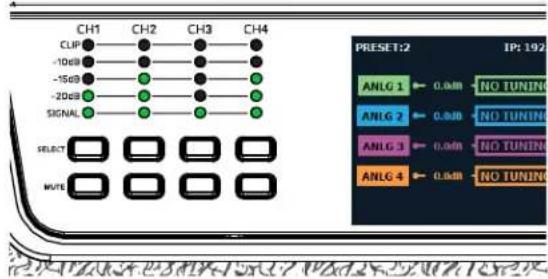
text_image
CH1 CH2 CH3 CH4 CLIP -10dB -15dB -20dB SIGNAL SELECT MUTE PRESET:2 IP: 192 ANLG 1 ← 0.0dB NO TUNIN ANLG 2 ← 0.0dB NO TUNIN ANLG 3 ← 0.0dB NO TUNIN ANLG 4 ← 0.0dB NO TUNINCONDITION: No sound, even though the Power LED is lit blue and the level meters indicate the amp is receiving an input signal.
POSSIBLE REASON:
- Speaker not connected. Power off the amplifier, disconnect the AC power cord, then verify speaker connection.
- Open circuit due to speaker failure. From the front panel display, determine which channel has the short. Power down the amplifier then disconnect the AC power cable. Remove the shorted load from the channel (and possibly attached cables) and have it checked by a qualified technician. Reconnect the power cord and power up the amplifier. If the shorted condition remains after the load is removed, the unit should serviced. See "Service" on page 88.
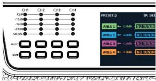
text_image
CH1 CH2 CH3 CH4 CLIP -10dB -15dB -20dB SIGNAL SELECT MUTE PRESET:2 IP: 192 ANLG 1 - 0.0dB NO TUNING ANLG 2 - 0.0dB NO TUNING ANLG 3 - 0.0dB NO TUNING ANLG 4 - 0.0dB NO TUNINGCONDITION: No input signal. Input signal indicator is not lighting, even though audio is being sent to the amplifier's input and the amp is powered on (blue Power indicator lit).
POSSIBLE REASON:
- Input signal level is very low. Double check the gain structure of the system and ensure that the amplifier's input trim levels are set accordingly.
- Input routing is not configured correctly for application. See "Assigning Input Sources" on page 14.
Signal Path Block Diagram
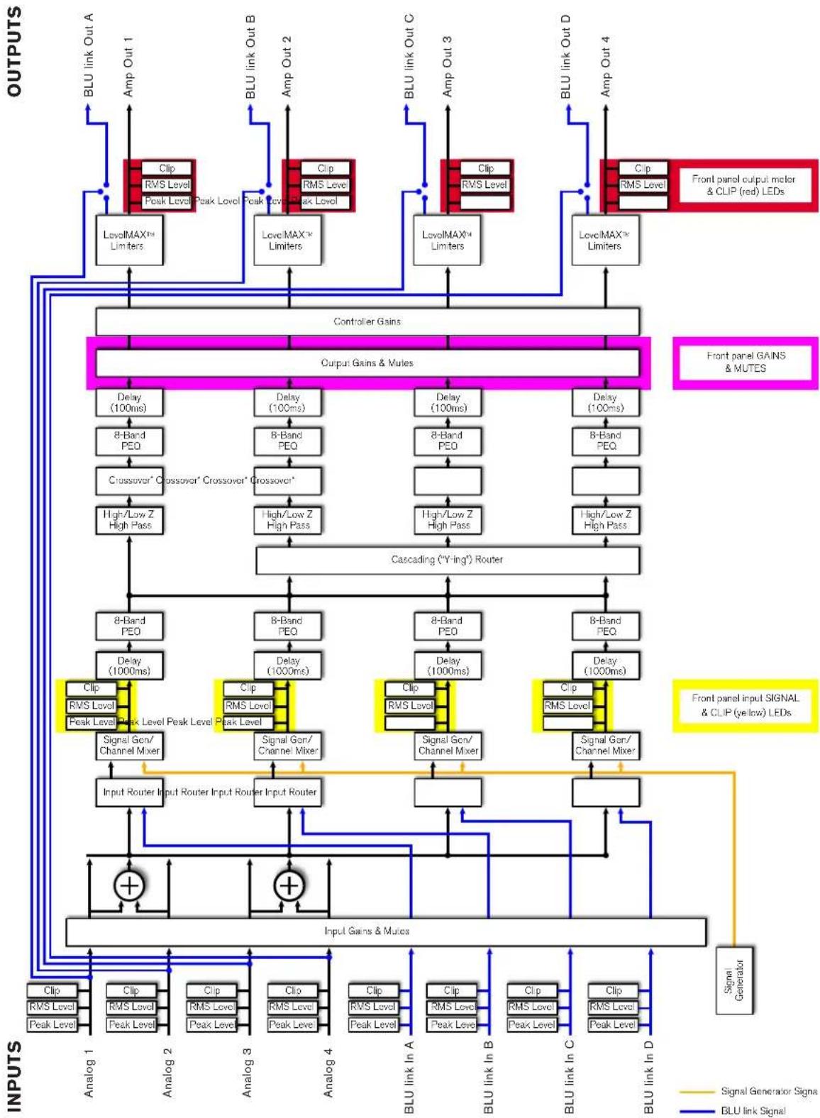
flowchart
graph TD
    subgraph INPUTS
        A["Input Generator"] --> B["Signal Generation Signal"]
        C["Input Gains & Mulics"] --> D["Output Gains & Mulies"]
    end

    subgraph INPUTS
        E["Inputs"] --> F["Blu link In A"]
        E --> G["Blu link In B"]
        E --> H["Blu link In C"]
        E --> I["Blu link In D"]
    end

    subgraph OUTPUTS
        J["Blu link Out A"] --> K["BLU link Out A"]
        J --> L["BLU link Out B"]
        J --> M["BLU link Out C"]
        J --> N["BLU link Out D"]
    end

    subgraph Controller Gains
        O["Controller Gains"] --> P["Output Gains & Mulies"]
    end

    subgraph INPUTS
        Q["Blu link Out A"] --> R["Blu link Out A"]
        Q --> S["Blu link Out B"]
        Q --> T["Blu link Out C"]
        Q --> U["Blu link Out D"]
    end

    subgraph Outputs
        V["Blu MAX™ Limiters"] --> W["8-Band PEQ"]
        X["Lowc MAX™ Limiters"] --> Y["Crossover* Crossover* Crossover*"]
        Z["High/Low Z High Pass"] --> AA["Cascading (Y-ing') Router"]
        AB["8-Band PEQ"] --> AC["8-Band PEQ"]
        AD["8-Band PEQ"] --> AE["8-Band PEQ"]
        AF["8-Band PEQ"] --> AG["8-Band PEQ"]
        AH["8-Band PEQ"] --> AI["8-Band PEQ"]
        AJ["8-Band PEQ"] --> AK["8-Band PEQ"]
        AL["8-Band PEQ"] --> AM["8-Band PEQ"]
    end

    subgraph Outputs
        AN["Delay (100ms)"] --> AO["8-Band PEQ"]
        AP["Delay (100ms)"] --> AQ["Crossover* Crossover* Crossover*"]
        AR["Delay (100ms)"] --> AS["Cascading (Y-ing') Router"]
        AT["8-Band PEQ"] --> AU["8-Band PEQ"]
        AV["8-Band PEQ"] --> AW["Cascading (Y-ing') Router"]
        AX["8-Band PEQ"] --> AY["8-Band PEQ"]
        AZ["8-Band PEQ"] --> BA["Cascading (Y-ing') Router"]
    end

    subgraph Outputs
        BB["Delay (100ms)"] --> BC["Crossover* Crossover* Crossover*"]
        BD["Delay (100ms)"] --> BE["Cascading (Y-ing') Router"]
        BF["Delay (100ms)"] --> BG["Cascading (Y-ing') Router"]
    end

    subgraph Outputs
        BH["Delay (100ms)"] --> BI["Crossover* Crossover* Crossover*"]
        BJ["Delay (100ms)"] --> BK["Cascading (Y-ing') Router"]
        BL["Delay (100ms)"] --> BLC["Cascading (Y-ing') Router"]
    end

    subgraph Outputs
        BM["Delay (100ms)"] --> BN["Crossover* Crossover* Crossover*"]
        BO["Delay (100ms)"] --> BP["Cascading (Y-ing') Router"]
    end

    subgraph Outputs
        BZ["Crossover* Crossover* Crossover*"]
        CA["Crossover* Crossover* Crossover*"]
    end

    subgraph Outputs
        CB["Crossover* Crossover* Crossover*"]
    end

    subgraph Outputs
        CC["Crossover* Crossover* Crossover*"]
    end

    subgraph Outputs
        DD["Crossover* Crossover* Crossover*"]
    end

    subgraph Outputs
        DE["Crossover* Crossover* Crossover*"]
    end

    subgraph Outputs
        EF["Crossover* Crossover* Crossover*"]
    end

    subgraph Outputs
        GF["Crossover* Crossover* Crossover*"]
    end

    subgraph Outputs
        GH["Crossover* Crossover* Crossover*"]
    end

    subgraph Outputs
        IG["Crossover* Crossover* Crossover*"]
    end

    subgraph Outputs
        H["Growth Rate"] --> I["Cascading (Y-ing') Router"]
    end

    subgraph Outputs
        J["Growth Rate"] --> K["Cascading (Y-ing') Router"]
    end

    subgraph Outputs
        L["Growth Rate"] --> M["Cascading (Y-ing') Router"]

    subgraph Outputs
        N["Growth Rate"] --> O["Cascading (Y-ing') Router"]

    subgraph Outputs
        P["Growth Rate"] --> Q["Cascading (Y-ing') Router"]

    subgraph Outputs
        R["Growth Rate"] --> S["Cascading (Y-ing') Router"]

    subgraph Outputs
        T["Growth Rate"] --> U["Cascading (Y-ing') Router"]

    subgraph Outputs
        V["Growth Rate"] --> W["Cascading (Y-ing') Router"]

    subgraph Outputs
        X["Growth Rate"] --> Y["Cascading (Y-ing') Router"]

    subgraph Outputs
        Z["Growth Rate"] --> AA["Cascading (Y-ing') Router"]

    subgraph Outputs
        AB["Growth Rate"] --> AC["Cascading (Y-ing') Router"]

    subgraph Outputs
        AD["Growth Rate"] --> AE["Cascading (Y-ing') Router"]

    subgraph Outputs
        AF["Growth Rate"] --> AG["Cascading (Y-ing') Router"]

    subgraph Outputs
        AH["Growth Rate"] --> AI["Cascading (Y-ing') Router"]

    subgraph Outputs
        AJ["Growth Rate"] --> AK["Cascading (Y-ing') Router"]

    subgraph Outputs
        AL["Growth Rate"] --> AM["Cascading (Y-ing') Router"]

    subgraph Outputs
        AN["Growth Rate"] --> AO["Cascading (Y-ing') Router"]

    subgraph Outputs
        AP["Growth Rate"] --> AQ["Cascading (Y-ing') Router"]

    subgraph Outputs
        AR["Growth Rate"] --> AS["Cascading (Y-ing') Router"]

    subgraph Outputs
        AT["Growth Rate"] --> AU["Cascading (Y-ing') Router"]

    subgraph Outputs
        AV["Growth Rate"] --> AW["Cascading (Y-ing') Router"]

    subgraph Outputs
        AX["Growth Rate"] --> AY["Cascading (Y-ing') Router"]

    subgraph Outputs
        AZ["Growth Rate"] --> BA["Cascading (Y-ing') Router"]

    subgraph Outputs
        AR["Growth Rate"] --> ASC["Cascading (Y-ing') Router"]

    subgraph Outputs
        ATG["Growth Rate"] --> AXA["Cascading (Y-ing') Router"]

    subgraph Outputs
        AZG["Growth Rate"] --> AXB["Cascading (Y-ing') Router"]

    subgraph Outputs
        AXG["Growth Rate"] --> AXC["Cascading (Y-ing') Router"]

    subgraph Outputs
        AYG["Growth Rate"] --> AXD["Cascading (Y-ing') Router"]

    subgraph Outputs
        AZH["Growth Rate"] --> AXE["Cascading (Y-ing') Router"]

    subgraph Outputs
        AYA["Growth Rate"] --> AXF["Cascading (Y-ing') Router"]

    subgraph Outputs
        AZI["Growth Rate"] --> AXG["Cascading (Y-ing') Router"]

    subgraph Outputs
        AYA2["Growth Rate"] --> AXI["Cascading (Y-ing') Router"]

    subgraph Outputs
        AZI3["Growth Rate"] --> AXJ["Cascading (Y-ing') Router"]

    subgraph Outputs
        AYA4["Growth Rate"] --> AXK["Cascading (Y-ing') Router"]

    subgraph Outputs
        AZI4["Growth Rate"] --> AXL["Cascading (Y-ing') Router"]

    subgraph Outputs
        AYA5["Growth Rate"] --> AXM["Cascading (Y-ing') Router"]

    subgraph Outputs
        AZI5["Growth Rate"] --> AXN["Cascading (Y-ing') Router"]

    subgraph Outputs
        AYA6["Growth Rate"] --> AXO["Cascading (Y-ing') Router"]

    subgraph Outputs
        AZI6["Growth Rate"] --> AXP["Cascading (Y-ing') Router"]

    end

    style Outputs fill:#f9f,stroke:#333,stroke-width:2px
Figure 83: Signal path block diagram (4-channel model with BLU link shown)
Factory Reset
The Factory Reset allows a CDi DriveCore amplifier to be reverted back to its factory default state. When initiated, the Factory Reset will perform the following tasks:
- Erase all user presets (this includes all user DSP and configuration settings)
- Reset all system settings
- Reset all BLU link settings (applicable to BLU link CDi DriveCore models only)
To perform the Factory Reset procedure:
Warning! All user presets will be permanently deleted and all settings reverted back to their factory default state. This process is irreversible. If you have any user presets you wish to keep, they should be backed up using Audio Architect before performing the Factory Reset. See "Managing Device & Preset Files" on page 47 for more information.
- Power off the amplifier by pressing and holding the Power button for 2 seconds.
- Press and hold the CH1 and CH2 SELECT buttons while powering on the amp. Continue to hold these buttons until the LCD reads: "Press MENU to restore Factory Settings or any other button to exit". Now release the SELECT buttons.
- Press and release the MENU button to start the Factory Reset procedure (pressing any other button will abort the Factory Reset procedure and the amp will boot up normally).
- Once the Factory Reset procedure begins, the LCD will display the message: "Restoring factory defaults!" and when complete, the device will boot up normally.
Specifications
Output Power: Dual Mode – All Channels Driven
| Amp Model Channels 2Ω 4Ω 8Ω 16Ω 70Vrms 100Vrms | ||||
| 2|300 / 2|300BL 2 150W 300W 300W 150W 300W 300W | ||||
| 4|300 / 4|300BL 4 150W 300W 300W 150W 300W 300W | ||||
| 2|600 / 2|600BL 2 300W 600W 600W 300W 600W 600W | ||||
| 4|600 / 4|600BL 4 300W 600W 600W 300W 600W 600W | ||||
| 2|1200 / 2|1200BL 2 850W 1200W 1200W 600W 1200W 1200W | ||||
| 4|1200 / 4|1200BL 4 850W 1200W 1200W 600W 1200W 1200W |
Minimum Guaranteed Power (1kHz, all channels driven, max distortion 0.5%, duration 0.5 seconds, 120 - 240Vrms \~50/60Hz)
Output Power: Bridge Mono Mode – All Channels Driven
| Amp Model 4Ω 8Ω 16Ω | 140Vrms 200Vrms | ||||
| 2|300 / 2|300BL | 300W | 600W | 600W | 600W | 600W |
| 4|300 / 4|300BL | 300W | 600W | 600W | 600W | 600W |
| 2|600 / 2|600BL | 600W | 1200W | 1200W | 1200W | 1200W |
| 4|600 / 4|600BL | 600W | 1200W | 1200W | 1200W | 1200W |
| 2|1200 / 2|1200BL | 1200W | 2400W | 2400W | 2400W | 2400W |
| 4|1200 / 4|1200BL | 1200W | 2400W | 2400W | 2400W | 2400W |
Minimum Guaranteed Power (1kHz, all channels driven, max distortion 0.5%, duration 0.5 seconds, 120 - 240Vrms \~50/60Hz)
Input Sensitivity
| Amp Model | 8Ω | 70Vrms | 100Vrms | ||||||
| 37dB Gain Mode | 34dB Gain Mode | 26dB Gain Mode | 37dB Gain Mode | 34dB Gain Mode | 26dB Gain Mode | 37dB Gain Mode | 34dB Gain Mode | 26dB Gain Mode | |
| 2|300 / 2|300BL | 0.7Vrms (-0.8dBu, -3.0dBV) | 1.0Vrms (2.2dBu, 0.0dBV) | 2.5Vrms (10.2dBu, 8.0dBV) | 1.0Vrms (2.2dBu, 0.0dBV) | 1.4Vrms (5.2dBu, 3.0dBV) | 3.5Vrms (13.2dBu, 11.0dBV) | 1.4Vrms (5.2dBu, 3.0dBV) | 2.0Vrms (8.2dBu, 6.0dBV) | 5.0Vrms (16.2dBu, 14.0dBV) |
| 4|300 / 4|300BL | 0.7Vrms (-0.8dBu, -3.0dBV) | 1.0Vrms (2.2dBu, 0.0dBV) | 2.5Vrms (10.2dBu, 8.0dBV) | 1.0Vrms (2.2dBu, 0.0dBV) | 1.4Vrms (5.2dBu,3.0dBV) | 3.5Vrms (13.2dBu, 11.0dBV) | 1.4Vrms (5.2dBu, 3.0dBV) | 2.0Vrms (8.2dBu, 6.0dBV) | 5.0Vrms (16.2dBu, 14.0dBV) |
| 2|600 / 2|600BL | 0.7Vrms (-0.8dBu, -3.0dBV) | 1.0Vrms (2.2dBu, 0.0dBV) | 2.5Vrms (10.2dBu, 8.0dBV) | 1.0Vrms (2.2dBu, 0.0dBV) | 1.4Vrms (5.2dBu, 3,0dBV) | 3.5Vrms (13.2dBu, 11.0dBV) | 1.4Vrms (5.2dBu, 3.0dBV) | 2.0Vrms (8.2dBu, 6.0dBV) | 5.0Vrms (16.2dBu, 14.0dBV) |
| 4|600 / 4|600BL | 0.7Vrms (-0.8dBu, -3.0dBV) | 1.0Vrms (2.2dBu, 0.0dBV) | 2.5Vrms (10.2dBu, 8.0dBV) | 1.0Vrms (2.2dBu, 0.0dBV) | 1.4Vrms (5.2dBu,3.3dBV) | 3.5Vrms (13.2dBu, 11.0dBV) | 1.4Vrms (5.2dBu, 3.0dBV) | 2.0Vrms (8.2dBu, 6.0dBV) | 5.0Vrms (16.2dBu, 14.0dBV) |
| 2|1200 / 2|1200BL | 0.7Vrms (-0.8dBu, -3.0dBV) | 1.0Vrms (2.2dBu, 0.0dBV) | 2.5Vrms (10.2dBu, 8.0dBV) | 1.0Vrms (2.2dBu, 0.0dBV) | 1.4Vrms (5.2dBu, 33.0dBV) | 3.5Vrms (13.2dBu, 11.0dBV) | 1.4Vrms (5.2dBu, 3.0dBV) | 2.0Vrms (8.2dBu, 6.0dBV) | 5.0Vrms (16.2dBu, 14.0dBV) |
| 4|1200 / 4|1200BL | 0.7Vrms (-0.8dBu, -3.0dBV) | 1.0Vrms (2.2dBu, 0.0dBV) | 2.5Vrms (10.2dBu, 8.0dBV) | 1.0Vrms (2.2dBu, 0.0dBV) | 1.4Vrms (5.2dBu 3.0dBV) | 3.5Vrms (13.2dBu, 11.0dBV) | 1.4Vrms (5.2dBu, 3.0dBV) | 2.0Vrms (8.2dBu, 6.0dBV) | 5.0Vrms (16.2dBu, 14.0dBV) |
Performance Specifications
| Specification Description | 2|300 / 2|300BL | 4|300 / 4|300BL | 600 / 2|600BL | 600 / 4|600BL | 2|1200 / 2|1200BL | 4|1200 / 4|1200BL |
| Digital Signal Processing | 96kHz, 32-bit floating point | 96kHz, 32-bit floating point | 96kHz, 32-bit floating point | 96kHz, 32-bit floating point | 96kHz, 32-bit floating point | 96kHz, 32-bit floating point |
| Voltage Gain (at maximum level setting) 4/8Ω, 70Vrms and 100Vrms Operation | 34dB 34dB 34 | dB 34dB 34dB 34dB | ||||
| Frequency Response (8Ω, 20Hz - 20kHz) | ±0.5dB ±0.5dB | ±0.5dB ±0.25dB ±0.25 | dB ±0.25dB | |||
| BLU link Signal-to-Noise Ratio (ref. rated power, 100V, 20Hz - 20kHz) | >108dB >108dB | >108dB >108dB >108dB | >108dB | |||
| Total Harmonic Distortion (at full rated power, from 20Hz - 20kHz) | 0.35% 0.35% | 0.35% 0.35% 0.35% 0.35% | ||||
| Analog Input Signal to Noise Ratio (ref. rated power, 100V, 20Hz - 20kHz) | >104dB >104dB | >104dB >104dB >104dB | >104dB | |||
| Intermodulation Distortion (60Hz and 7kHz at 4:1, from - 30dB to full rated power) | ≤0.35% ≤0.35% | ≤0.35% ≤0.35% ≤0.35% | ≤0.35% | |||
| Damping Factor (20Hz to 100Hz) | >1000 >1000 | >1000 >1000 >1000 | >1000 | |||
| Crosstalk (below rated power, 20Hz to 1kHz) | >80dB >80dB | >80dB >80dB >80dB | >80dB | |||
| Common Mode Rejection (20Hz to 1kHz, typical) | >70dB >70dB | >70dB >70dB >70dB | >70dB | |||
| DC Output Offset (with inputs shorted) | ±10mV ±10mV | ±10mV ±10mV ±10mV | ±10mV | |||
| Input Impedance (Nominally balanced, nominally unbalanced) | 20 kΩ balanced, 10 kΩ unbalanced | 20 kΩ balanced, 10 kΩ unbalanced | 20 kΩ balanced, 10 kΩ unbalanced | 10 kΩ balanced, 5 kΩ unbalanced | 10 kΩ balanced, 5 kΩ unbalanced | 10 kΩ balanced, 5 kΩ unbalanced |
| Maximum Input Level (Low Amp Gain Mode) | +20dB U +20dB U | +20dB U +20dB U +20dB U | +20dB U +20dB U | |||
| Required AC Mains (±10%) | 100V - 240V~ 50/60Hz | 100V - 240V~ 50/60Hz | 100V - 240V~ 50/60Hz | 100V - 240V~ 50/60Hz | 100V - 240V~ 50/60Hz | 100V - 240V~ 50/60Hz |
| Cooling | Continuously variable speed forced air, front-to-back airflow | Continuously variable speed forced air, front-to-back airflow | Continuously variable speed forced air, front-to-back airflow | Continuously variable speed forced air, front-to-back airflow | Continuously variable speed forced air, front-to-back airflow | Continuously variable speed forced air, front-to-back airflow |
| Power Supply Connector | Standard IEC type 320 inlet for detachable connector 100 - 240 V~ | Standard IEC type 320 inlet for detachable connector 100 - 240 V~ | Standard IEC type 320 inlet for detachable connector 100 - 240 V~ | 15A IEC Connector, 100-240V | 15A IEC Connector, 100-240V | 20A IEC Connector, 100-240V |
| Load Impedance Stereo/Dual Mode | 2Ω - 16Ω; 70Vrms and 100Vrms | 2Ω - 16Ω; 70Vrms and 100Vrms | 2Ω - 16Ω; 70Vrms and 100Vrms | 2Ω - 16Ω; 70Vrms and 100Vrms | 2Ω - 16Ω; 70Vrms and 100Vrms | 2Ω - 16Ω; 70Vrms and |
| Load Impedance Bridge Mono | 4Ω - 16Ω; 140Vrms and 200Vrms | 4Ω - 16Ω; 140Vrms and 200Vrms | 4Ω - 16Ω; 140Vrms and 200Vrms | 4Ω - 16Ω; 140Vrms and 200Vrms | 4Ω - 16Ω; 140Vrms and 200Vrms | 4Ω - 16Ω; 1 |
| Maximum Fan Noise (re dB SPL @ 1M) | 51dBA 51dBA | 51dBA 51dBA 54dBA | 54dBA | |||
| Weight | 14.56 lbs (6.6 kg) | 16.13 lbs (7.31 kg) | 14.56 lbs (6.6 kg) | 16.3 lbs (7.39 kg) | 17.2 lbs (7.8 kg) | 20.1 lbs (9.12 kg) |
Dimensions
2|300 / 2|300BL / 4|300 / 4|300BL / 2|600 / 2|600BL / 4|600 / 4|600BL
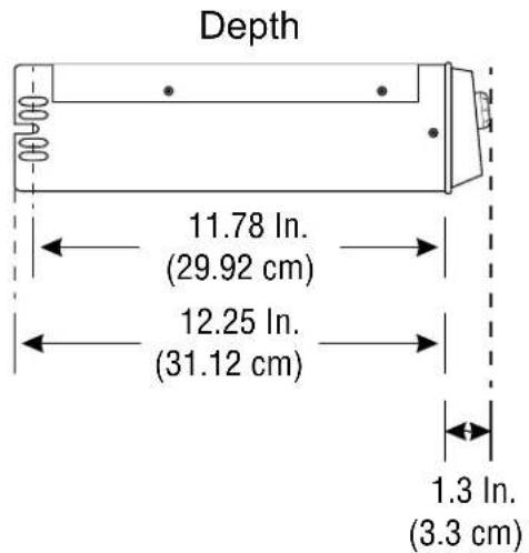
text_image
Depth 11.78 In. (29.92 cm) 12.25 In. (31.12 cm) 1.3 In. (3.3 cm)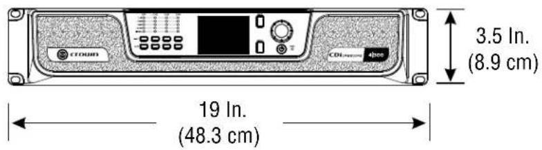
text_image
CROWN CDL-2000-4000 3.5 In. (8.9 cm) 19 In. (48.3 cm)2|1200 / 2|1200BL / 4|1200 / 4|1200BL
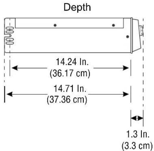
text_image
Depth 14.24 In. (36.17 cm) 14.71 In. (37.36 cm) 1.3 In. (3.3 cm)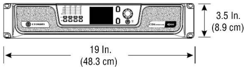
text_image
CROWN 3.5 In. (8.9 cm) 19 In. (48.3 cm)AC Power Draw & Thermal Dissipation
CDi DriveCore 2|300 / 2|300BL
Pink noise 12dB crest factor, bandwidth limited 22Hz to 22kHz.
Typical line impedance used.
Data based on all channels driven.
This product was safety certified to ± 10% of the voltage range 100 - 240V . This information is for reference only.
| CDi DriveCore 2|300 / 2|300BL - Dual | |||||||||
| 120 VAC / 60Hz 230 VAC / 50Hz | |||||||||
| Condition Load | Line current (amps) | Power Dissipated as Heat Line | current (amps) | Power Dissipated as Heat | |||||
| watts BTU kcal/hr watts | BTU kcal/hr | ||||||||
| At Idle Awake | N/A 0.6 73 2 | 51 63 0.4 1 | 02 347 88 | ||||||
| 1/8 Power Pink Noise Typical of program material just at clip | 2Ω | 1.1 | 91 | 310 | 78 | 0.7 | 119 | 405 | 102 |
| 4Ω | 1.4 | 97 | 331 | 83 | 0.8 | 118 | 403 | 102 | |
| 8Ω | 1.4 | 86 | 295 | 74 | 0.8 | 108 | 368 | 93 | |
| 70V | 1.3 | 83 | 282 | 71 | 0.8 | 102 | 350 | 88 | |
| 100V | 1.3 | 80 | 272 | 69 | 0.8 | 102 | 347 | 87 | |
| 1/3 Power Pink Noise Typical of program material at extreme clip | 2Ω | 1.9 | 123 | 419 | 106 | 1.1 | 140 | 479 | 121 |
| 4Ω | 2.8 | 138 | 471 | 119 | 1.5 | 150 | 512 | 129 | |
| 8Ω | 2.6 | 116 | 397 | 100 | 1.4 | 125 | 428 | 108 | |
| 70V | 2.5 | 110 | 377 | 95 | 1.4 | 115 | 391 | 99 | |
| 100V | 2.5 | 99 | 337 | 85 | 1.3 | 381 | 381 | 96 | |
| CDi DriveCore 2|300 / 2|300BL – Bridged | |||||||||
| 120 VAC / 60Hz 230 VAC / 50Hz | |||||||||
| Condition Load | Line current (amps) | Power Dissipated as Heat Line | current (amps) | Power Dissipated as Heat | |||||
| watts BTU kcal/hr watts | BTU kcal/hr | ||||||||
| At Idle Awake | N/A 0.6 73 2 | 50 63 0.4 1 | 02 | 348 88 | |||||
| 1/8 Power Pink Noise Typical of program material just at clip | 4Ω | 1.4 | 92 | 313 | 79 | 0.8 | 112 | 382 | 96 |
| 8Ω | 1.3 | 84 | 286 | 72 | 0.8 | 107 | 365 | 92 | |
| 70V | 1.3 | 79 | 271 | 68 | 0.8 | 102 | 349 | 88 | |
| 100V | 1.3 | 79 | 271 | 68 | 0.8 | 101 | 345 | 87 | |
| 1/3 Power Pink Noise Typical of program material at extreme clip | 4Ω | 2.8 | 127 | 432 | 109 | 1.5 | 138 | 471 | 119 |
| 8Ω | 2.7 | 112 | 381 | 96 | 1.4 | 123 | 419 | 106 | |
| 70V | 2.5 | 101 | 344 | 87 | 1.3 | 111 | 378 | 95 | |
| 100V | 2.5 | 99 | 338 | 85 | 1.3 | 111 | 378 | 95 | |
CDi DriveCore 4|300 / 4|300BL
Pink noise 12dB crest factor, bandwidth limited 22Hz to 22kHz.
Typical line impedance used.
Data based on all channels driven.
This product was safety certified to ±10% of the voltage range 100–240V\~. This information is for reference only.
| CDi DriveCore 4|300 / 4|300BL - Dual | |||||||||
| 120 VAC / 60Hz 230 VAC / 50Hz | |||||||||
| Condition Load | Line current (amps) | Power Dissipated as Heat | Line current (amps) | Power Dissipated as Heat | |||||
| watts BTU kcal/hr watts | BTU kcal/hr watts | BTU kcal/hr watts | |||||||
| At Idle Awake | N/A | 0.9 | 110 | 375 | 94 | 0.5 | 125 | 428 | 108 |
| 1/8 Power Pink Noise Typical of program material just at clip | 2Ω | 1.8 | 139 | 475 | 120 | 1.0 | 160 | 544 | 137 |
| 4Ω | 2.6 | 160 | 544 | 137 | 1.4 | 173 | 591 | 149 | |
| 8Ω | 2.4 | 140 | 477 | 120 | 1.3 | 150 | 511 | 129 | |
| 70V | 2.3 | 129 | 441 | 111 | 1.3 | 142 | 484 | 122 | |
| 100V | 2.3 | 127 | 434 | 109 | 1.3 | 141 | 481 | 121 | |
| 1/3 Power Pink Noise Typical of program material at extreme clip | 2Ω | 3.5 | 215 | 733 | 185 | 1.8 | 221 | 754 | 190 |
| 4Ω | 5.3 | 239 | 815 | 205 | 2.8 | 239 | 814 | 205 | |
| 8Ω | 5.0 | 200 | 683 | 172 | 2.6 | 211 | 719 | 181 | |
| 70V | 4.7 | 175 | 598 | 151 | 2.5 | 181 | 617 | 155 | |
| 100V | 4.7 | 166 | 568 | 143 | 2.5 | 180 | 615 | 155 | |
| CDi DriveCore 4|300 / 4|300BL – Bridged | |||||||||
| 120 VAC / 60Hz 230 VAC / 50Hz | |||||||||
| Condition Load | Line current (amps) | Power Dissipated as Heat | Line current (waps) BT | Power Dissipated as Heat | |||||
| watts BT | U kcal/hr | U kcal/hr | |||||||
| At Idle Awake | N/A | 0.9 | 110 | 376 | 95 | 0.5 | 126 | 429 | 108 |
| 1/8 Power Pink Noise Typical of program material just at clip | 4Ω | 2.6 | 157 | 537 | 135 | 1.4 | 169 | 575 | 145 |
| 8Ω | 2.4 | 139 | 474 | 120 | 1.3 | 149 | 508 | 128 | |
| 70V | 2.4 | 132 | 449 | 113 | 1.3 | 143 | 488 | 123 | |
| 100V | 2.3 | 129 | 441 | 111 | 1.3 | 143 | 487 | 123 | |
| 1/3 Power Pink Noise Typical of program material at extreme clip | 4Ω | 5.3 | 232 | 791 | 199 | 2.8 | 232 | 793 | 200 |
| 8Ω | 4.9 | 192 | 655 | 165 | 2.6 | 208 | 710 | 179 | |
| 70V | 4.8 | 177 | 605 | 153 | 2.5 | 183 | 623 | 157 | |
| 100V | 4.8 | 182 | 622 | 157 | 2.5 | 181 | 617 | 156 | |
CDi DriveCore 2|600 / 2|600BL
Pink noise 12dB crest factor, bandwidth limited 22Hz to 22kHz.
Typical line impedance used.
Data based on all channels driven.
This product was safety certified to ±10% of the voltage range 100–240V\~. This information is for reference only.
| CDi DriveCore 2|600 / 2|600BL - Dual | |||||||||
| 120 VAC / 60Hz 230 VAC / 50Hz | |||||||||
| Condition Load | Line current (amps) | Power Dissipated as Heat | Line current/hr (amps) | Power Dissipated as Heat | |||||
| watts BTU kcal/hr watts BTU kcal | |||||||||
| At Idle Awake N/A | 0.6 69 235 59 0.4 91 3 | 2 79 | |||||||
| 1/8 Power Pink Noise Typical of program material just at clip | 2Ω | 1.6 | 112 | 384 | 97 | 0.9 | 124 | 424 | 107 |
| 4Ω | 2.2 | 119 | 406 | 102 | 1.2 | 130 | 443 | 112 | |
| 8Ω | 2.1 | 102 | 348 | 88 | 1.2 | 119 | 407 | 103 | |
| 70V | 2.1 | 107 | 366 | 92 | 1.1 | 116 | 398 | 100 | |
| 100V | 2.0 | 94 | 322 | 81 | 1.1 | 105 | 359 | 90 | |
| 1/3 Power Pink Noise Typical of program material at extreme clip | 2Ω | 3.2 | 179 | 610 | 154 | 1.6 | 178 | 608 | 153 |
| 4Ω | 4.9 | 195 | 665 | 168 | 2.6 | 210 | 715 | 180 | |
| 8Ω | 4.6 | 164 | 559 | 141 | 2.5 | 176 | 600 | 151 | |
| 70V | 4.5 | 149 | 509 | 128 | 2.4 | 171 | 582 | 147 | |
| 100V | 4.7 | 182 | 622 | 157 | 2.3 | 153 | 521 | 131 | |
| CDi DriveCore 2|600 / 2|600BL – Bridged | |||||||||
| 120 VAC / 60Hz 230 VAC / 50Hz | |||||||||
| Condition Load | Line current (amps) | Power Dissipated as Heat | Line current (amps) BT | Power Dissipated as Heat | |||||
| watts BT | U kcal/hr | U kcal/hr | |||||||
| At Idle Awake | N/A | 0.6 | 69 | 235 | 59 | 0.4 | 91 | 311 | 78 |
| 1/8 Power Pink Noise Typical of program material just at clip | 4Ω | 2.3 | 118 | 404 | 102 | 1.2 | 126 | 431 | 109 |
| 8Ω | 2.1 | 102 | 350 | 88 | 1.2 | 113 | 386 | 97 | |
| 70V | 2.1 | 108 | 367 | 93 | 1.2 | 113 | 387 | 97 | |
| 100V | 2.1 | 95 | 323 | 81 | 1.1 | 108 | 368 | 93 | |
| 1/3 Power Pink Noise Typical of program material at extreme clip | 4Ω | 5.1 | 199 | 680 | 171 | 2.6 | 199 | 678 | 171 |
| 8Ω | 4.7 | 168 | 573 | 144 | 2.5 | 171 | 583 | 147 | |
| 70V | 4.7 | 162 | 553 | 139 | 2.4 | 167 | 571 | 144 | |
| 100V | 4.5 | 147 | 502 | 126 | 2.4 | 153 | 521 | 131 | |
CDi DriveCore 4|600 / 4|600BL
Pink noise 12dB crest factor, bandwidth limited 22Hz to 22kHz.
Typical line impedance used.
Data based on all channels driven.
This product was safety certified to ±10% of the voltage range 100–240V\~. This information is for reference only.
| CDi DriveCore 4|600 / 4|600BL - Dual | |||||||||
| 120 VAC / 60Hz 230 VAC / 50Hz | |||||||||
| Condition Load | Line current (amps) | Power Dissipated as Heat | Line current hr (amps) | Power Dissipated as Heat | |||||
| watts BTU kcal/hr watts BTU kcal | |||||||||
| At Idle Awake | N/A | 0.9 | 108 | 369 | 93 | 0.6 | 106 | 361 | 91 |
| 1/8 Power Pink Noise Typical of program material just at clip | 2Ω | 4.2 | 225 | 770 | 194 | 2.3 | 213 | 726 | 183 |
| 4Ω | 4.5 | 201 | 686 | 173 | 2.0 | 191 | 652 | 164 | |
| 8Ω | 4.3 | 178 | 609 | 153 | 2.3 | 164 | 560 | 141 | |
| 70V | 4.1 | 176 | 601 | 152 | 2.3 | 174 | 593 | 149 | |
| 100V | 4.1 | 172 | 588 | 148 | 2.2 | 144 | 493 | 124 | |
| 1/3 Power Pink Noise Typical of program material at extreme clip | 2Ω | 8.2 | 363 | 1238 | 312 | 4.8 | 379 | 1294 | 326 |
| 4Ω | 9.4 | 434 | 1483 | 374 | 4.5 | 330 | 1127 | 284 | |
| 8Ω | 9.8 | 308 | 1053 | 265 | 5.0 | 273 | 933 | 235 | |
| 70V | 9.5 | 310 | 1058 | 267 | 5.1 | 443 | 1512 | 381 | |
| 100V | 5.0 | 178 | 609 | 154 | 2.7 | 169 | 578 | 146 | |
| CDi DriveCore 4|600 / 4|600BL – Bridged | |||||||||
| 120 VAC / 60Hz 230 VAC / 50Hz | |||||||||
| Condition Load | Line current (amps) | Power Dissipated as Heat | Line current hr (amps) | Power Dissipated as Heat | |||||
| watts BTU kcal/hr watts BTU kcal | |||||||||
| At Idle Awake | N/A | 1.0 | 108 | 368 | 93 | 0.6 | 108 | 369 | 93 |
| 1/8 Power Pink Noise Typical of program material just at clip | 4Ω | 4.4 | 206 | 703 | 177 | 2.3 | 196 | 669 | 169 |
| 8Ω | 4.1 | 173 | 589 | 149 | 2.3 | 181 | 617 | 155 | |
| 70V | 4.1 | 185 | 631 | 159 | 2.3 | 174 | 593 | 150 | |
| 100V | 4.0 | 162 | 551 | 139 | 2.1 | 154 | 527 | 133 | |
| 1/3 Power Pink Noise Typical of program material at extreme clip | 4Ω | 9.7 | 386 | 1318 | 332 | 4.9 | 329 | 1122 | 283 |
| 8Ω | 8.8 | 299 | 1022 | 258 | 5.0 | 277 | 945 | 238 | |
| 70V | 9.0 | 325 | 1109 | 280 | 4.9 | 291 | 993 | 250 | |
| 100V | 8.8 | 277 | 945 | 238 | 4.7 | 238 | 814 | 205 | |
CDi DriveCore 2|1200 / 2|1200BL
Pink noise 12dB crest factor, bandwidth limited 22Hz to 22kHz.
Typical line impedance used.
Data based on all channels driven.
This product was safety certified to ±10% of the voltage range 100–240V\~. This information is for reference only.
| CDi DriveCore 2|1200 / 2|1200BL - Dual | |||||||||
| 120 VAC / 60Hz 230 VAC / 50Hz | |||||||||
| Condition Load | Line current (amps) | Power Dissipated as Heat | Line current /hr (amps) | Power Dissipated as Heat | |||||
| watts BTU kcal/hr watts BTU kcal | |||||||||
| At Idle Awake N/A | 0.6 68 231 58 0.4 65 | 222 56 | |||||||
| 1/8 Power Pink Noise Typical of program material just at clip | 2Ω | 3.7 | 167 | 570 | 144 | 2.0 | 149 | 509 | 128 |
| 4Ω | 4.0 | 145 | 493 | 124 | 2.1 | 135 | 460 | 116 | |
| 8Ω | 7.2 | 110 | 376 | 95 | 2.1 | 120 | 411 | 104 | |
| 70V | 3.8 | 145 | 494 | 125 | 2.1 | 139 | 475 | 120 | |
| 100V | 3.6 | 130 | 442 | 112 | 2.0 | 117 | 398 | 100 | |
| 1/3 Power Pink Noise Typical of program material at extreme clip | 2Ω | 5.4 | 204 | 696 | 175 | 3.9 | 266 | 909 | 229 |
| 4Ω | 9.1 | 257 | 876 | 221 | 4.6 | 244 | 833 | 210 | |
| 8Ω | 8.1 | 209 | 712 | 179 | 4.5 | 196 | 668 | 168 | |
| 70V | 8.2 | 265 | 903 | 228 | 4.7 | 313 | 1068 | 269 | |
| 100V | 9.1 | 250 | 852 | 215 | 4.2 | 205 | 701 | 177 | |
| CDi DriveCore 2|1200 / 2|1200BL – Bridged | |||||||||
| 120 VAC / 60Hz | 230 VAC / 50Hz | ||||||||
| Condition Load | Line current (amps) | Power Dissipated as Heat | Line current (amps) watts | Power Dissipated as Heat | |||||
| watts | BTU kcal/hr | BTU kcal/hr | |||||||
| At Idle Awake | N/A | 0.6 | 68 | 231 | 58 | 0.4 | 65 | 222 | 56 |
| 1/8 Power Pink Noise Typical of program material just at clip | 4Ω | 4.0 | 162 | 552 | 139 | 2.1 | 145 | 496 | 125 |
| 8Ω | 3.8 | 130 | 443 | 112 | 2.0 | 124 | 423 | 107 | |
| 70V | 3.9 | 155 | 530 | 134 | 2.0 | 140 | 478 | 120 | |
| 100V | 3.5 | 132 | 450 | 113 | 2.1 | 138 | 472 | 119 | |
| 1/3 Power Pink Noise Typical of program material at extreme clip | 4Ω | 8.8 | 285 | 971 | 245 | 4.5 | 236 | 805 | 203 |
| 8Ω | 8.7 | 235 | 801 | 202 | 4.7 | 213 | 728 | 183 | |
| 70V | 8.9 | 303 | 1033 | 260 | 4.6 | 269 | 918 | 231 | |
| 100V | 8.8 | 243 | 829 | 209 | 4.9 | 257 | 879 | 222 | |
CDi DriveCore 4|1200 / 4|1200BL
Pink noise 12dB crest factor, bandwidth limited 22Hz to 22kHz.
Typical line impedance used.
Data based on all channels driven.
This product was safety certified to ±10% of the voltage range 100–240V\~. This information is for reference only.
| CDi DriveCore 4|1200 / 4|1200BL - Dual | |||||||||
| 120 VAC / 60Hz 230 VAC / 50Hz | |||||||||
| Condition Load | Line current (amps) | Power Dissipated as Heat | Line current (amps) | Power Dissipated as Heat | |||||
| watts BTU kcal/hr watts | BTU kcal/hr watts | BTU kcal/hr watts | |||||||
| At Idle Awake | N/A | 0.4 | 37 | 126 | 32 | 0.6 | 105 | 358 | 90 |
| 1/8 Power Pink Noise Typical of program material just at clip | 2Ω | 6.8 | 293 | 1002 | 253 | 3.5 | 278 | 949 | 239 |
| 4Ω | 7.6 | 262 | 896 | 226 | 4.1 | 257 | 878 | 221 | |
| 8Ω | 7.0 | 219 | 748 | 188 | 3.8 | 214 | 730 | 184 | |
| 70V | 7.2 | 256 | 873 | 220 | 4.0 | 259 | 885 | 223 | |
| 100V | 7.2 | 213 | 726 | 183 | 3.6 | 212 | 723 | 182 | |
| 1/3 Power Pink Noise Typical of program material at extreme clip | 2Ω | 17.0 | 679 | 2316 | 584 | 7.8 | 538 | 1836 | 463 |
| 4Ω | 17.2 | 516 | 1761 | 444 | 2.5 | 470 | 1603 | 404 | |
| 8Ω | 17.4 | 404 | 1378 | 347 | 8.7 | 400 | 1367 | 345 | |
| 70V | 15.0 | 460 | 1568 | 395 | 9.2 | 546 | 1865 | 470 | |
| 100V | 17.7 | 392 | 1337 | 337 | 8.8 | 398 | 1358 | 342 | |
| CDi DriveCore 4|1200 / 4|1200BL – Bridged | |||||||||
| 120 VAC / 60Hz | 230 VAC / 50Hz | ||||||||
| Condition | Load | Line current (amps) | Power Dissipated as Heat | Line current (amps) BTU kcal/hr | Power Dissipated as Heat | ||||
| watts BTU kcal/hr | WARS BTU kcal/hr | ||||||||
| At Idle Awake | N/A | 0.9 | 109 | 372 | 94 | 0.5 | 106 | 362 | 91 |
| 1/8 Power Pink Noise Typical of program material just at clip | 4Ω | 7.8 | 284 | 971 | 245 | 3.8 | 265 | 903 | 228 |
| 8Ω | 7.3 | 237 | 811 | 204 | 3.5 | 223 | 762 | 192 | |
| 70V | 7.4 | 290 | 990 | 250 | 3.6 | 273 | 932 | 235 | |
| 100V | 7.4 | 269 | 920 | 232 | 3.6 | 255 | 871 | 219 | |
| 1/3 Power Pink Noise Typical of program material at extreme clip | 4Ω | 17.4 | 539 | 1840 | 464 | 8.0 | 446 | 1524 | 384 |
| 8Ω | 16.9 | 449 | 1532 | 386 | 7.6 | 425 | 1450 | 366 | |
| 70V | 17.5 | 545 | 1858 | 468 | 7.7 | 549 | 1874 | 472 | |
| 100V | 17.5 | 532 | 1817 | 458 | 7.2 | 490 | 1671 | 421 | |
Warranty (United States Only)
SUMMARY OF WARRANTY
Crown International, 1718 West Mishawaka Road, Elkhart, Indiana 46517-4095 U.S.A. warrants to you, the ORIGINAL PURCHASER and ANY SUBSEQUENT OWNER of each NEW Crown product, for three years from the date of purchase by the original purchaser (the "warranty period") that the new Crown product is free of defects in materials and workmanship. We further warrant the new Crown product regardless of the reason for failure, except as excluded in this Warranty.
* Warranty is only valid within the United States of America. For information on Warranty outside of the U.S.A, please contact your local distributor.

ITEMS EXCLUDED FROM THIS CROWN WARRANTY
This Crown Warranty is in effect only for failure of a new Crown product which occurred within the Warranty Period. It does not cover any product which has been damaged because of any intentional misuse, accident, negligence, or loss which is covered under any of your insurance contracts. This Crown Warranty also does not extend to the new Crown product if the serial number has been defaced, altered, or removed.
WHAT THE WARRANTOR WILL DO
We will remedy any defect, regardless of the reason for failure (except as excluded), by repair, replacement, or refund. We may not elect refund unless you agree, or unless we are unable to provide replacement, and repair is not practical or cannot be timely made. If a refund is elected, then you must make the defective or malfunctioning product available to us free and clear of all liens or other encumbrances. The refund will be equal to the actual purchase price, not including interest, insurance, closing costs, and other finance charges less a reasonable depreciation on the product from the date of original purchase. Warranty work can only be performed at our authorized service centers or at the factory. Warranty work for some products can only be performed at our factory. We will remedy the defect and ship the product from the service center or our factory within a reasonable time after receipt of the defective product at our authorized service center or our factory. All expenses in remedying the defect, including surface shipping costs in the United States, will be borne by us. (You must bear the expense of shipping the product between any foreign country and the port of entry in the United States including the return shipment, and all taxes, duties, and other customs fees for such foreign shipments.)
HOW TO OBTAIN WARRANTY SERVICE
You must notify us of your need for warranty service within the warranty period. All components must be shipped in a factory pack, which, if needed, may be obtained from us free of charge. Corrective action will be taken within a reasonable time of the date of receipt of the defective product by us or our authorized service center. If the repairs made by us or our authorized service center are not satisfactory, notify us or our authorized service center immediately.
DISCLAIMER OF CONSEQUENTIAL AND INCIDENTAL DAMAGES
YOU ARE NOT ENTITLED TO RECOVER FROM US ANY INCIDENTAL DAMAGES RESULTING FROM ANY DEFECT IN THE NEW CROWN PRODUCT. THIS INCLUDES ANY DAMAGE TO ANOTHER PRODUCT OR PRODUCTS RESULTING FROM SUCH A DEFECT. SOME STATES DO NOT ALLOW THE EXCLUSION OR LIMITATIONS OF INCIDENTAL OR CONSEQUENTIAL DAMAGES, SO THE ABOVE LIMITATION OR EXCLUSION MAY NOT APPLY TO YOU.
WARRANTY ALTERATIONS
No person has the authority to enlarge, amend, or modify this Crown Warranty. This Crown Warranty is not extended by the length of time which you are deprived of the use of the new Crown product. Repairs and replacement parts provided under the terms of this Crown Warranty shall carry only the unexpired portion of this Crown Warranty.
DESIGN CHANGES
We reserve the right to change the design of any product from time to time without notice and with no obligation to make corresponding changes in products previously manufactured.
LEGAL REMEDIES OF PURCHASER
THIS CROWN WARRANTY GIVES YOU SPECIFIC LEGAL RIGHTS, YOU MAY ALSO HAVE OTHER RIGHTS WHICH VARY FROM STATE TO STATE. No action to enforce this Crown Warranty shall be commenced after expiration of the warranty period.
THIS STATEMENT OF WARRANTY SUPERSEDES ANY OTHERS CONTAINED IN THIS MANUAL FOR CROWN PRODUCTS. 04/15
Service
Crown products are quality units that rarely require servicing. Before returning your unit for servicing, please contact Crown Technical Support to verify the need for servicing.
Warranty is only valid within the country in which the product was purchased.
This unit has very sophisticated circuitry which should only be serviced by a fully trained technician. This is one reason why each unit bears the following label:

CAUTION: To prevent electric shock, do not remove covers. No user serviceable parts inside. Refer servicing to a qualified technician.
Complete the Service Return Authorization form in the back of this manual, when returning a Crown product to the factory or authorized service center. The form must be included with your product inside the box or in a packing slip envelope securely attached to the outside of the shipping carton. Do not send this form separately.
Worldwide Service
Service may be obtained from an authorized service center (contact your local Crown/Amcron representative or our office for a list of authorized service centers). To obtain service, simply present the bill of sale as proof of purchase along with the defective unit to an authorized service center. They will handle the necessary paperwork and repair.
Remember to transport your unit in the original factory pack.
US and Canada Service
Service may be obtained in one of two ways: from an authorized service center or from the factory. You may choose either. It is important that you have your copy of the bill of sale as your proof of purchase.
Service at a US or Canada Service Center
This method usually saves the most time and effort. Simply present your bill of sale along with the defective unit to an authorized service center to obtain service. They will handle the necessary paperwork and repair. Remember to transport the unit in the original factory pack. A list of authorized service centers in your area can be obtained from Crown Factory Service, or online from www.crownaudio.com/en/support/service_lookup
Factory Service
Crown accepts no responsibility for non-serviceable product that is sent to us for factory repair. It is the owner's responsibility to ensure that their product is serviceable prior to sending it to the factory.
A Service Return Authorization (SRA) is required for product being sent to the factory for repair. An SRA can be completed online at www.crownaudio.com/support/rma. If you do not have access to the web, please call Customer Service at 574.294.8200 or 800.342.6939 extension 8205 in North America, Puerto Rico and the Virgin Islands only.
For warranty service, we will pay for ground shipping both ways in the United States. Contact Customer Service to obtain prepaid shipping labels prior to sending the unit. Or, if you prefer, you may prepay the cost of shipping, and HARMAN will reimburse you. Send copies of the shipping receipts to HARMAN to receive reimbursement.
Your repaired unit will be returned via UPS ground. Please contact us if other arrangements are required.
Factory Service Shipping Instructions
- Service Return Authorization (SRA) is required for product being sent to the factory for service. Please complete the SRA by going to www.crownaudio.com/support/rma. If you do not have access to our website, call 1.800.342.6939, extension 8205 and we will create the SRA for you.
- See packing instructions that follow.
- Ship product to: HARMAN Factory Service 1718 W Mishawaka Rd. Elkhart, IN 46517
- Use a bold black marker and write the SRA number on three sides of the box.
- Record the SRA number for future reference. The SRA number can be used to check the repair status.
Packing Instructions
Important: These instructions must be followed. If they are not followed, HARMAN International, Inc. assumes no responsibility for damaged goods and/or accessories that are sent with your unit.
- Fill out and include the Service Return Authorization Request in the back of this manual.
- Do not ship any accessories (manuals, cords, hardware, etc.) with your unit. These items are not needed to service your product. We will not be responsible for these items.
- When shipping your Crown product, it is important that it has adequate protection. We recommend you use the original pack material when returning the product for repair. If you do not have the original box, please call HARMAN at 800.342.6939 or 574.294.8210 and order new pack material. (Do not ship your unit in a wood or metal cabinet).
- If you provide your own shipping pack, the minimum recommended requirements for materials are as follows:
a. 275 P.S.I. burst test, double-wall carton that allows for 2-inch solid Styrofoam on all six sides of unit or 3 inches of plastic bubble wrap on all six sides of unit.
b. Securely seal the package with an adequate carton sealing tape.
c. Do not use light boxes or "peanuts". Damage caused by poor packaging will not be covered under warranty.
Enclose the completed Service Return Authorization Request (or securely attach it to the outside of carton) and re-seal the shipping pack with a sturdy carton sealing tape.
Estimate Approval
Approval of estimate must be given within 30 days after being notified by HARMAN International. Units still in the possession of HARMAN after 30 days of the estimate will become the property of HARMAN International.
Payment of Non-Warranty Repairs
Payment on out-of-warranty repairs must be received within 30 days of the repair date. Units unclaimed after 30 days become the property of HARMAN International.
If you have any questions, please contact HARMAN.
HARMAN Factory Service
1718 W. Mishawaka Rd.,
Elkhart, Indiana 46517 U.S.A.
Telephone:
574-294-8200
800-342-6939 (North America, Puerto Rico, and Virgin Islands only)
Facsimile:
574-294-8301 (Technical Support)
574-294-8124 (Factory Service)
Web site:
www.crownaudio.com
Service Return Authorization Request
Shipping Address: HARMAN Factory Service, 1718 W. Mishawaka Rd., Elkhart, IN 46517
You may also request a service return authorization at www.crownaudio.com/support/rma
PLEASE PRINT CLEARLY
SRA #: ____ (If sending product to Crown factory service)
Model: ____ Serial Number: ____ Purchase Date: ____
PRODUCT RETURN INFORMATION
Individual or Business Name: ____
Phone #: ____ Fax #: ____ E-Mail: ____
Street Address (please, no P.O. Boxes): ____
City: ____ State/Prov: ____ Postal Code: ____ Country: ____
Nature of problem: ____
Other equipment in your system: ____
If warranty is expired, please provide method of payment. Proof of purchase may be required to validate warranty.
PAYMENT OPTIONS
☐ I have open account payment terms. Purchase order required. PO#: ____ ☐ COD
□ Credit Card (Information below is required; however if you do not want to provide this information at this time, we will contact you when your unit is repaired for the information.)
Credit card information:
Type of credit card: MasterCard Visa American Express Discover □
Type of credit card account: Personal/Consumer Business/Corporate
Card # ____ Exp. date: ____ *Card ID #: ____
*Card ID # is located on the back of the card following the credit card #, in the signature area. On American Express, it may be located on the front of the card. This number is required to process the charge to your account. If you do not want to provide it at this time, we will call you to obtain this number when the repair of your unit is complete.
Name on credit card: ____
Billing address of credit card: ____
Open Source Disclaimer for HARMAN Products
IMPORTANT READ CAREFULLY
This product includes several open source software libraries and tools. Open source software is governed by the terms and conditions of the applicable open source license. You are bound by the terms and conditions of the open source license in connection with your use and distribution of the software in this product.
The open source software, applicable licenses and other notices are identified in the table below. You agree to comply with all such licenses and other notices. If you do not agree to such terms, you may not install, download, or otherwise use the open source software other than as a component of this HARMAN product. General descriptions of Open Source license types can be found at www.opensource.org/licenses. Where specific open source license terms entitle you to the source or object code of this software, source or object code is available here: www.harman.com/opensource. If you have any questions about the open source software contained in this product, please email support@harman.com. In the subject line of your email, please reference: "Open Source Software".
Open Source Licenses and Copyright Notices
The following table lists the open source software included in this product. The web site and the open source license type for each tool is specified. The individual web sites contain the explicit license details for the library or tool.
| Library / Tool Web Site License | ||
| buildroot https://buildroot.org/ | GNU GPLv2GNU GPLv3GNU LGPLv2 | |
| Lua http://lua.org MIT | ||
| zlib http://boost.org Boost License | ||
| augeas 1.4.0 http://augeas.net/ GNU LGPLv2.1 | ||
| libfa http://augeas.net/libfa/ GNU LGPLv2 or greater | ||
| dhcpd 6.11.3 http://roy.marples.name/projects/dhcpcd/index BSD | ||
| gdb and/or gdbserver 7.10.1 | http://www.gnu.org/software/gdb/current/ | GNU GPLv2 |
| libxml2 2.9.3 | http://xmlsoft.org/ | MIT |
| BOOST 1.53.0 | http://www.boost.org/ | Boost Software License - Version 1.0 - August 17th, 2003 |
| JSON 0.6.0-rc2 | https://github.com/open-source-parsers/jsoncpp | MIT |
| tinyXML | https://sourceforge.net/projects/tinyxml/ | zlib/libpng |
| ticpp (tinyXML++) | https://github.com/rjpcomputing/ticpp MIT | |
| sqlite 3.8.4.3 | https://www.sqlite.org/ | public domain |
| Qt qt-everywhere-opensource-src-4.8.6 | https://download.qt.io/archive/qt/4.8/4.8.6/ | GNU LGPLv2.1 |
| lua | http://www.lua.org/about.html | MIT |
| at91bootstrap | http://www.at91.com/linux4sam/bin/view/Linux4SAM/AT91Bootstrap | 2-clause BSD |
| uBoot | http://www.at91.com/linux4sam/bin/view/Linux4SAM/U-Boot | GNU GPLv2 |
| Linux kernel 3.10 | https://github.com/linux4sam/linux-at91 | GNU GPLv2 |
| busybox 1.20.2 | http://www.busybox.net | GNU GPLv2 |
| MTD utils 1.5.0 | http://www.linux-mtd.infradead.org/ | GNU GPLv2 |
| MD5 | http://userpages.umbc.edu/~mabzug1/cs/md5/md5.html | RSA Data Security, Inc. MD5 Message-Digest Algorithm |
| util-linux www.kernel.org/pub/linux/utils | util-linux/ | GNU GPLv2GNU GPLv2+GNU LGPLv2+BSD |
| procps http://procps.sf.net | GNU GPLv2GNU LGPLv2 | |
| glibc 2.18 www.gnu.org/software/libc/ | GNU GPLv2+GNU LGPLv2.1+ | |
| iproute2 | https://wiki.linuxfoundation.org/networking/iproute2 | GNU GPLv2 |
| wireless tools for linux | http://www.labs.hpe.com/personal/Jean_Tourrilhes/Linux/Tools.html | GNU GPLv2 |
| abxtest | https://github.com/GiterLab/arm-201311/blob/master/arm-none-linux-gnueabi/libc/usr/bin/abxtest | GNU GPLv2 |
| alsa | http://alsa-project.org/main/index.php/Main_Page | GNU GPLv3GNU LGPLv3 |
| bzip2 http://www.bzip.org/ BSD | ||
| directFB http://www.directfb.org/ GNU LGPLv2.1 | ||
| fontconfig | https://www.freedesktop.org/wiki/Software/fontconfig/ | Copyright © 2000,2001,2002,2003,2004,2006,2007Keith PackardCopyright © 2005 Patrick LamCopyright © 2009 Roozbeh PournaderCopyright © 2008,2009 Red Hat, Inc.Copyright © 2008 Danilo ŠeganCopyright © 2012 Google, Inc. |
| ffmpeg https://ffmpeg.org/ | GNU GPLv2+GNU LGPLv2.1+ | |
| e2fsprogs http://e2fsprogs.sourceforge.net/ GNU GPLv2 | ||
| expat http://www.libexpat.org/ MIT | ||
| libffi https://sourceware.org/libffi/ | MIT | |
| freetype | https://www.freetype.org/license.html | GNU GPLv2 |
| gio | https://developer.gnome.org/gio/stable/ | GNU LGPLv2.1 |
| GLib | wiki.gnome.org/Projects/GLib | GNU LGPLv2.1 |
| libjpeg ijg.org | Custom BSD-like | |
| MPEG Audio Decoder | http://www.underbit.com/products/mad/ | GNU GPLv2 |
| ncurses | www.gnu.org/software/ncurses/ncurses.html | X11 |
| i2C Tools for Linux | http://freecode.com/projects/i2ctools | GNU GPLv2 |
| libstdc++ | https://gcc.gnu.org/onlinedocs/libstdc++/ | GNU GPLv3 + GCC Runtime Library Exception, v3.1 |
| udev | www.freedesktop.org/software/systemd/man/udev.html | GNU GPLv2 |
| zlib | http://www.zlib.net/ | zlib |
| fbv | http://freecode.com/projects/fbv | GNU GPLv2 |
| gdbus, gdbus-codegeniperf https://iperf.fr/ BSD | http://www.glk.org/ | GNU LGPLv2+ |
| jpegtran http://www.ijg.org/ MIT | ||
| usbutils | http://www.linuxfromscratch.org/blfs/view/svn/general/usbutils.html | GNU GPLv2+ |
| libusb | http://www.linuxfromscratch.org/blfs/view/svn/general/libusb.html | GNU LGPLv2.1 |
| Rng-tools | https://git.kernel.org/cgit/utils/kernel/rng-tools/rng-tools.git/ | GNU GPLv2 |
| OpenSSH http://www.openssh.com/ BSD | ||
| ethtool www.kernel.org/pub/software/network/ethtool/ GNU GPLv2 | ||
| OpenSSL https://www.openssl.org/ | SSLeayOpenSSL | |
| libpng http://www.libpng.org/pub/png/libpng.html libpng | ||
| fdformat ftp://ftp.kernel.org/pub/linux/utils/util-linux-ng/ | GNU GPLv2GNU GPLv2+GNU LGPLv2+BSD | |
| mii-diag http://ftp.psu.ac.th/pub/scyld/mi-diag.c GPLv2 | ||
| top (included with Procps-ng) | https://sourceforge.net/projects/procps-ng/ | GNU GPLv2GNU LGPLv2 |
| udevadm | https://kernel.googlesource.com/pub/scm/linux/hotplug/udev/+/118/udevadm.c | GPLv2 |
| libproc-3.2.8.so | https://rpmfind.net/linux/RPM/sourceforge/m/ma/magicspecs/apt/3.0/x86_64/RPMS.p/procps-3.2.8-25.20110302gitmgc30.x86_64.html | GNU GPLv2+GNU LGPLv2+ |
| e2fsprogs | http://e2fsprogs.sourceforge.net/ | GNU GPLv2GNU LGPLv2 |
GNU General Public License Version 2
GNU GENERAL PUBLIC LICENSE
Version 2, June 1991
Copyright (C) 1989, 1991 Free Software Foundation, Inc.
51 Franklin Street, Fifth Floor, Boston, MA 02110-1301, USA
Everyone is permitted to copy and distribute verbatim copies of this license document, but changing it is not allowed.
Preamble
The licenses for most software are designed to take away your freedom to share and change it. By contrast, the GNU General Public License is intended to guarantee your freedom to share and change free software--to make sure the software is free for all its users. This General Public License applies to most of the Free Software Foundation's software and to any other program whose authors commit to using it. (Some other Free Software Foundation software is covered by the GNU Lesser General Public License instead.) You can apply it to your programs, too.
When we speak of free software, we are referring to freedom, not price. Our General Public Licenses are designed to make sure that you have the freedom to distribute copies of free software (and charge for this service if you wish), that you receive source code or can get it if you want it, that you can change the software or use pieces of it in new free programs; and that you know you can do these things.
To protect your rights, we need to make restrictions that forbid anyone to deny you these rights or to ask you to surrender the rights. These restrictions translate to certain responsibilities for you if you distribute copies of the software, or if you modify it.
For example, if you distribute copies of such a program, whether gratis or for a fee, you must give the recipients all the rights that you have. You must make sure that they, too, receive or can get the source code. And you must show them these terms so they know their rights.
We protect your rights with two steps: (1) copyright the software, and (2) offer you this license which gives you legal permission to copy, distribute and/or modify the software.
Also, for each author's protection and ours, we want to make certain that everyone understands that there is no warranty for this free software. If the software is modified by someone else and passed on, we want its recipients to know that what they have is not the original, so that any problems introduced by others will not reflect on the original authors' reputations.
Finally, any free program is threatened constantly by software patents. We wish to avoid the danger that redistributors of a free program will individually obtain patent licenses, in effect making the program proprietary. To prevent this, we have made it clear that any patent must be licensed for everyone's free use or not licensed at all.
The precise terms and conditions for copying, distribution and modification follow.
TERMS AND CONDITIONS FOR COPYING, DISTRIBUTION AND MODIFICATION
- This License applies to any program or other work which contains a notice placed by the copyright holder saying it may be distributed under the terms of this General Public License. The "Program", below, refers to any such program or work, and a "work based on the Program" means either the Program or any derivative work under copyright law: that is to say, a work containing the Program or a portion of it, either verbatim or with modifications and/or translated into another language. (Hereinafter, translation is included without limitation in the term "modification".) Each licensee is addressed as "you".
Activities other than copying, distribution and modification are not covered by this License; they are outside its scope. The act of running the Program is not restricted, and the output from the Program is covered only if its contents constitute a work based on the Program (independent of having been made by running the Program). Whether that is true depends on what the Program does.
- You may copy and distribute verbatim copies of the Program's source code as you receive it, in any medium, provided that you conspicuously and appropriately publish on each copy an appropriate copyright notice and disclaimer of warranty; keep intact all the notices that refer to this License and to
the absence of any warranty; and give any other recipients of the Program a copy of this License along with the Program.
You may charge a fee for the physical act of transferring a copy, and you may at your option offer warranty protection in exchange for a fee.
- You may modify your copy or copies of the Program or any portion of it, thus forming a work based on the Program, and copy and distribute such modifications or work under the terms of Section 1 above, provided that you also meet all of these conditions:
a) You must cause the modified files to carry prominent notices stating that you changed the files and the date of any change.
b) You must cause any work that you distribute or publish, that in whole or in part contains or is derived from the Program or any part thereof, to be licensed as a whole at no charge to all third parties under the terms of this License.
c) If the modified program normally reads commands interactively when run, you must cause it, when started running for such interactive use in the most ordinary way, to print or display an announcement including an appropriate copyright notice and a notice that there is no warranty (or else, saying that you provide a warranty) and that users may redistribute the program under these conditions, and telling the user how to view a copy of this License. (Exception: if the Program itself is interactive but does not normally print such an announcement, your work based on the Program is not required to print an announcement.)
These requirements apply to the modified work as a whole. If identifiable sections of that work are not derived from the Program, and can be reasonably considered independent and separate works in themselves, then this License, and its terms, do not apply to those sections when you distribute them as separate works. But when you distribute the same sections as part of a whole which is a work based on the Program, the distribution of the whole must be on the terms of this License, whose permissions for other licensees extend to the entire whole, and thus to each and every part regardless of who wrote it.
Thus, it is not the intent of this section to claim rights or contest your rights to work written entirely by you; rather, the intent is to exercise the right to control the distribution of derivative or collective works based on the Program.
In addition, mere aggregation of another work not based on the Program with the Program (or with a work based on the Program) on a volume of a storage or distribution medium does not bring the other work under the scope of this License.
- You may copy and distribute the Program (or a work based on it, under Section 2) in object code or executable form under the terms of Sections 1 and 2 above provided that you also do one of the following:
a) Accompany it with the complete corresponding machine-readable source code, which must be distributed under the terms of Sections 1 and 2 above on a medium customarily used for software interchange; or,
b) Accompany it with a written offer, valid for at least three years, to give any third party, for a charge no more than your cost of physically performing source distribution, a complete machine-readable copy of the corresponding source code, to be distributed under the terms of Sections 1 and 2 above on a medium customarily used for software interchange; or,
c) Accompany it with the information you received as to the offer to distribute corresponding source code. (This alternative is allowed only for noncommercial distribution and only if you received the program in object code or executable form with such an offer, in accord with Subsection b above.)
The source code for a work means the preferred form of the work for making modifications to it. For an executable work, complete source code means all the source code for all modules it contains, plus any associated interface definition files, plus the scripts used to control compilation and installation of the executable. However, as a special exception, the source code distributed need not include anything that is normally distributed (in either source or binary form) with the major components (compiler, kernel, and so on) of the operating system on which the executable runs, unless that component itself accompanies the executable.
If distribution of executable or object code is made by offering access to copy from a designated place, then offering equivalent access to copy the source
code from the same place counts as distribution of the source code, even though third parties are not compelled to copy the source along with the object code.
- You may not copy, modify, sublicense, or distribute the Program except as expressly provided under this License. Any attempt otherwise to copy, modify, sublicense or distribute the Program is void, and will automatically terminate your rights under this License. However, parties who have received copies, or rights, from you under this License will not have their licenses terminated so long as such parties remain in full compliance.
- You are not required to accept this License, since you have not signed it. However, nothing else grants you permission to modify or distribute the Program or its derivative works. These actions are prohibited by law if you do not accept this License. Therefore, by modifying or distributing the Program (or any work based on the Program), you indicate your acceptance of this License to do so, and all its terms and conditions for copying, distributing or modifying the Program or works based on it.
- Each time you redistribute the Program (or any work based on the Program), the recipient automatically receives a license from the original licensor to copy, distribute or modify the Program subject to these terms and conditions. You may not impose any further restrictions on the recipients' exercise of the rights granted herein. You are not responsible for enforcing compliance by third parties to this License.
- If, as a consequence of a court judgment or allegation of patent infringement or for any other reason (not limited to patent issues), conditions are imposed on you (whether by court order, agreement or otherwise) that contradict the conditions of this License, they do not excuse you from the conditions of this License. If you cannot distribute so as to satisfy simultaneously your obligations under this License and any other pertinent obligations, then as a consequence you may not distribute the Program at all. For example, if a patent license would not permit royalty-free redistribution of the Program by all those who receive copies directly or indirectly through you, then the only way you could satisfy both it and this License would be to refrain entirely from distribution of the Program.
If any portion of this section is held invalid or unenforceable under any particular circumstance, the balance of the section is intended to apply and the section as a whole is intended to apply in other circumstances.
It is not the purpose of this section to induce you to infringe any patents or other property right claims or to contest validity of any such claims; this section has the sole purpose of protecting the integrity of the free software distribution system, which is implemented by public license practices. Many people have made generous contributions to the wide range of software distributed through that system in reliance on consistent application of that system; it is up to the author/donor to decide if he or she is willing to distribute software through any other system and a licensee cannot impose that choice.
This section is intended to make thoroughly clear what is believed to be a consequence of the rest of this License.
- If the distribution and/or use of the Program is restricted in certain countries either by patents or by copyrighted interfaces, the original copyright holder who places the Program under this License may add an explicit geographical distribution limitation excluding those countries, so that distribution is permitted only in or among countries not thus excluded. In such case, this License incorporates the limitation as if written in the body of this License.
- The Free Software Foundation may publish revised and/or new versions of the General Public License from time to time. Such new versions will be similar in spirit to the present version, but may differ in detail to address new problems or concerns.
Each version is given a distinguishing version number. If the Program specifies a version number of this License which applies to it and "any later version", you have the option of following the terms and conditions either of that version or of any later version published by the Free Software Foundation. If the Program does not specify a version number of this License, you may choose any version ever published by the Free Software Foundation.
- If you wish to incorporate parts of the Program into other free programs whose distribution conditions are different, write to the author to ask for permission. For software which is copyrighted by the Free Software Foundation, write to the Free Software Foundation; we sometimes make exceptions for this. Our decision will be guided by the two goals of preserving the free status of all derivatives of our free software and of promoting the sharing and reuse of software generally.
NO WARRANTY
- BECAUSE THE PROGRAM IS LICENSED FREE OF CHARGE, THERE IS NO WARRANTY FOR THE PROGRAM, TO THE EXTENT PERMITTED BY APPLICABLE LAW. EXCEPT WHEN OTHERWISE STATED IN WRITING THE COPYRIGHT HOLDERS AND/OR OTHER PARTIES PROVIDE THE PROGRAM "AS IS" WITHOUT WARRANTY OF ANY KIND, EITHER EXPRESSED OR IMPLIED, INCLUDING, BUT NOT LIMITED TO, THE IMPLIED WARRANTIES OF MERCHANTABILITY AND FITNESS FOR A PARTICULAR PURPOSE. THE ENTIRE RISK AS TO THE QUALITY AND PERFORMANCE OF THE PROGRAM IS WITH YOU. SHOULD THE PROGRAM PROVE DEFECTIVE, YOU ASSUME THE COST OF ALL NECESSARY SERVICING, REPAIR OR CORRECTION.
- IN NO EVENT UNLESS REQUIRED BY APPLICABLE LAW OR AGREED TO IN WRITING WILL ANY COPYRIGHT HOLDER, OR ANY OTHER PARTY WHO MAY MODIFY AND/OR REDISTRIBUTE THE PROGRAM AS PERMITTED ABOVE, BE LIABLE TO YOU FOR DAMAGES, INCLUDING ANY GENERAL, SPECIAL, INCIDENTAL OR CONSEQUENTIAL DAMAGES ARISING OUT OF THE USE OR INABILITY TO USE THE PROGRAM (INCLUDING BUT NOT LIMITED TO LOSS OF DATA OR DATA BEING RENDERED INACCURATE OR LOSSES SUSTAINED BY YOU OR THIRD PARTIES OR A FAILURE OF THE
PROGRAM TO OPERATE WITH ANY OTHER PROGRAMS), EVEN IF SUCH HOLDER OR OTHER PARTY HAS BEEN ADVISED OF THE POSSIBILITY OF SUCH DAMAGES.
END OF TERMS AND CONDITIONS
How to Apply These Terms to Your New Programs
If you develop a new program, and you want it to be of the greatest possible use to the public, the best way to achieve this is to make it free software which everyone can redistribute and change under these terms.
To do so, attach the following notices to the program. It is safest to attach them to the start of each source file to most effectively convey the exclusion of warranty; and each file should have at least the "copyright" line and a pointer to where the full notice is found.
one line to give the program's name and an idea of what it does.
Copyright (C) yyyy name of author
This program is free software; you can redistribute it and/or modify it under the terms of the GNU General Public License as published by the Free Software Foundation; either version 2 of the License, or (at your option) any later version.
This program is distributed in the hope that it will be useful, but WITHOUT ANY WARRANTY; without even the implied warranty of MERCHANTABILITY or FITNESS FOR A PARTICULAR PURPOSE. See the GNU General Public License for more details.
You should have received a copy of the GNU General Public License along with this program; if not, write to the Free Software Foundation, Inc., 51 Franklin Street, Fifth Floor, Boston, MA 02110-1301, USA.
Also add information on how to contact you by electronic and paper mail.
If the program is interactive, make it output a short notice like this when it starts in an interactive mode:
Gnomovision version 69, Copyright (C) year name of author Gnomovision comes with ABSOLUTELY NO WARRANTY; for details type `show w'. This is free software, and you are welcome to redistribute it under certain conditions; type `show c' for details.
The hypothetical commands `show w' and `show c' should show the appropriate parts of the General Public License. Of course, the commands you use may be called something other than `show w' and `show c'; they could even be mouse-clicks or menu items--whatever suits your program.
You should also get your employer (if you work as a programmer) or your school, if any, to sign a "copyright disclaimer" for the program, if necessary. Here is a sample; alter the names:
Yoyodyne, Inc., hereby disclaims all copyright
interest in the program `Gnomovision'
(which makes passes at compilers) written
by James Hacker.
signature of Ty Coon, 1 April 1989
Ty Coon, President of Vice
This General Public License does not permit incorporating your program into proprietary programs. If your program is a subroutine library, you may consider it more useful to permit linking proprietary applications with the library. If this is what you want to do, use the GNU Lesser General Public License instead of this License.
GNU General Public License Version 3
GNU GENERAL PUBLIC LICENSE
Version 3, 29 June 2007
Copyright © 2007 Free Software Foundation, Inc. http://fsf.org/
Everyone is permitted to copy and distribute verbatim copies of this license document, but changing it is not allowed.
Preamble
The GNU General Public License is a free, copyleft license for software and other kinds of works.
The licenses for most software and other practical works are designed to take away your freedom to share and change the works. By contrast, the GNU General Public License is intended to guarantee your freedom to share and change all versions of a program--to make sure it remains free software for all its users. We, the Free Software Foundation, use the GNU General Public License for most of our software; it applies also to any other work released this way by its authors. You can apply it to your programs, too.
When we speak of free software, we are referring to freedom, not price. Our General Public Licenses are designed to make sure that you have the freedom to distribute copies of free software (and charge for them if you wish), that you receive source code or can get it if you want it, that you can change the software or use pieces of it in new free programs, and that you know you can do these things.
To protect your rights, we need to prevent others from denying you these rights or asking you to surrender the rights. Therefore, you have certain responsibilities if you distribute copies of the software, or if you modify it: responsibilities to respect the freedom of others.
For example, if you distribute copies of such a program, whether gratis or for a fee, you must pass on to the recipients the same freedoms that you received. You must make sure that they, too, receive or can get the source code. And you must show them these terms so they know their rights.
Developers that use the GNU GPL protect your rights with two steps: (1) assert copyright on the software, and (2) offer you this License giving you legal permission to copy, distribute and/or modify it.
For the developers' and authors' protection, the GPL clearly explains that there is no warranty for this free software. For both users' and authors' sake, the GPL requires that modified versions be marked as changed, so that their problems will not be attributed erroneously to authors of previous versions.
Some devices are designed to deny users access to install or run modified versions of the software inside them, although the manufacturer can do so. This is fundamentally incompatible with the aim of protecting users' freedom to change the software. The systematic pattern of such abuse occurs in the area of products for individuals to use, which is precisely where it is most unacceptable. Therefore, we have designed this version of the GPL to prohibit the practice for those products. If such problems arise substantially in other domains, we stand ready to extend this provision to those domains in future versions of the GPL, as needed to protect the freedom of users.
Finally, every program is threatened constantly by software patents. States should not allow patents to restrict development and use of software on general-purpose computers, but in those that do, we wish to avoid the special danger that patents applied to a free program could make it effectively proprietary. To prevent this, the GPL assures that patents cannot be used to render the program non-free.
The precise terms and conditions for copying, distribution and modification follow.
TERMS AND CONDITIONS
- Definitions.
"This License" refers to version 3 of the GNU General Public License.
"Copyright" also means copyright-like laws that apply to other kinds of works, such as semiconductor masks.
"The Program" refers to any copyrightable work licensed under this License. Each licensee is addressed as "you". "Licensees" and "recipients" may be individuals or organizations.
To “modify” a work means to copy from or adapt all or part of the work in a fashion requiring copyright permission, other than the making of an exact copy. The resulting work is called a “modified version” of the earlier work or a work “based on” the earlier work.
A "covered work" means either the unmodified Program or a work based on the Program.
To “propagate” a work means to do anything with it that, without permission, would make you directly or secondarily liable for infringement under applicable copyright law, except executing it on a computer or modifying a private copy. Propagation includes copying, distribution (with or without modification), making available to the public, and in some countries other activities as well.
To “convey” a work means any kind of propagation that enables other parties to make or receive copies. Mere interaction with a user through a computer network, with no transfer of a copy, is not conveying.
An interactive user interface displays “Appropriate Legal Notices” to the extent that it includes a convenient and prominently visible feature that (1) displays an appropriate copyright notice, and (2) tells the user that there is no warranty for the work (except to the extent that warranties are provided), that licensees may convey the work under this License, and how to view a copy of this License. If the interface presents a list of user commands or options, such as a menu, a prominent item in the list meets this criterion.
1. Source Code.
The “source code” for a work means the preferred form of the work for making modifications to it. “Object code” means any non-source form of a work.
A “Standard Interface” means an interface that either is an official standard defined by a recognized standards body, or, in the case of interfaces specified for a particular programming language, one that is widely used among developers working in that language.
The “System Libraries” of an executable work include anything, other than the work as a whole, that (a) is included in the normal form of packaging a Major Component, but which is not part of that Major Component, and (b) serves only to enable use of the work with that Major Component, or to implement a Standard Interface for which an implementation is available to the public in source code form. A “Major Component”, in this context, means a major essential component (kernel, window system, and so on) of the specific operating system (if any) on which the executable work runs, or a compiler used to produce the work, or an object code interpreter used to run it.
The “Corresponding Source” for a work in object code form means all the source code needed to generate, install, and (for an executable work) run the object code and to modify the work, including scripts to control those activities. However, it does not include the work's System Libraries, or general-purpose tools or generally available free programs which are used unmodified in performing those activities but which are not part of the work. For example, Corresponding Source includes interface definition files associated with source files for the work, and the source code for shared libraries and dynamically linked subprograms that the work is specifically designed to require, such as by intimate data communication or control flow between those subprograms and other parts of the work.
The Corresponding Source need not include anything that users can regenerate automatically from other parts of the Corresponding Source.
The Corresponding Source for a work in source code form is that same work.
2. Basic Permissions.
All rights granted under this License are granted for the term of copyright on the Program, and are irrevocable provided the stated conditions are met. This License explicitly affirms your unlimited permission to run the unmodified Program. The output from running a covered work is covered by this License only if the output, given its content, constitutes a covered work. This License acknowledges your rights of fair use or other equivalent, as provided by copyright law.
You may make, run and propagate covered works that you do not convey, without conditions so long as your license otherwise remains in force. You may convey covered works to others for the sole purpose of having them make modifications exclusively for you, or provide you with facilities for running those works, provided that you comply with the terms of this License in conveying all material for which you do not control copyright. Those thus making or running the covered works for you must do so exclusively on your behalf, under your direction and control, on terms that prohibit them from making any copies of your copyrighted material outside their relationship with you.
Conveying under any other circumstances is permitted solely under the conditions stated below. Sublicensing is not allowed; section 10 makes it unnecessary.
3. Protecting Users' Legal Rights From Anti-Circumvention Law.
No covered work shall be deemed part of an effective technological measure under any applicable law fulfilling obligations under article 11 of the WIPO copyright treaty adopted on 20 December 1996, or similar laws prohibiting or restricting circumvention of such measures.
When you convey a covered work, you waive any legal power to forbid circumvention of technological measures to the extent such circumvention is effected by exercising rights under this License with respect to the covered work, and you disclaim any intention to limit operation or modification of the work as a means of enforcing, against the work's users, your or third parties' legal rights to forbid circumvention of technological measures.
4. Conveying Verbatim Copies.
You may convey verbatim copies of the Program's source code as you receive it, in any medium, provided that you conspicuously and appropriately publish on each copy an appropriate copyright notice; keep intact all notices stating that this License and any non-permissive terms added in accord with section 7 apply to the code; keep intact all notices of the absence of any warranty; and give all recipients a copy of this License along with the Program.
You may charge any price or no price for each copy that you convey, and you may offer support or warranty protection for a fee.
5. Conveying Modified Source Versions.
You may convey a work based on the Program, or the modifications to produce it from the Program, in the form of source code under the terms of section 4, provided that you also meet all of these conditions:
a) The work must carry prominent notices stating that you modified it, and giving a relevant date.
b) The work must carry prominent notices stating that it is released under this License and any conditions added under section 7. This requirement modifies the requirement in section 4 to "keep intact all notices".
c) You must license the entire work, as a whole, under this License to anyone who comes into possession of a copy. This License will therefore apply, along with any applicable section 7 additional terms, to the whole of the work, and all its parts, regardless of how they are packaged. This License gives no permission to license the work in any other way, but it does not invalidate such permission if you have separately received it.
d) If the work has interactive user interfaces, each must display Appropriate Legal Notices; however, if the Program has interactive interfaces that do not display Appropriate Legal Notices, your work need not make them do so.
A compilation of a covered work with other separate and independent works, which are not by their nature extensions of the covered work, and which are not combined with it such as to form a larger program, in or on a volume of a storage or distribution medium, is called an “aggregate” if the compilation and its resulting copyright are not used to limit the access or legal rights of the compilation's users beyond what the individual works permit. Inclusion of a covered work in an aggregate does not cause this License to apply to the other parts of the aggregate.
6. Conveying Non-Source Forms.
You may convey a covered work in object code form under the terms of sections 4 and 5, provided that you also convey the machine-readable Corresponding Source under the terms of this License, in one of these ways:
a) Convey the object code in, or embodied in, a physical product (including a physical distribution medium), accompanied by the Corresponding Source fixed on a durable physical medium customarily used for software interchange.
b) Convey the object code in, or embodied in, a physical product (including a physical distribution medium), accompanied by a written offer, valid for at least three years and valid for as long as you offer spare parts or customer support for that product model, to give anyone who possesses the object code either (1) a copy of the Corresponding Source for all the software in the product that is covered by this License, on a durable physical medium customarily used for software interchange, for a price no more than your reasonable cost of physically performing this conveying of source, or (2) access to copy the Corresponding Source from a network server at no charge.
c) Convey individual copies of the object code with a copy of the written offer to provide the Corresponding Source. This alternative is allowed only occasionally and noncommercially, and only if you received the object code with such an offer, in accord with subsection 6b.
d) Convey the object code by offering access from a designated place (gratis or for a charge), and offer equivalent access to the Corresponding Source in the same way through the same place at no further charge. You need not require recipients to copy the Corresponding Source along with the object code. If the place to copy the object code is a network server, the Corresponding Source may be on a different server (operated by you or a third party) that supports equivalent copying facilities, provided you maintain clear directions next to the object code saying where to find the
Corresponding Source. Regardless of what server hosts the Corresponding Source, you remain obligated to ensure that it is available for as long as needed to satisfy these requirements.
e) Convey the object code using peer-to-peer transmission, provided you inform other peers where the object code and Corresponding Source of the work are being offered to the general public at no charge under subsection 6d.
A separable portion of the object code, whose source code is excluded from the Corresponding Source as a System Library, need not be included in conveying the object code work.
A “User Product” is either (1) a “consumer product”, which means any tangible personal property which is normally used for personal, family, or household purposes, or (2) anything designed or sold for incorporation into a dwelling. In determining whether a product is a consumer product, doubtful cases shall be resolved in favor of coverage. For a particular product received by a particular user, “normally used” refers to a typical or common use of that class of product, regardless of the status of the particular user or of the way in which the particular user actually uses, or expects or is expected to use, the product. A product is a consumer product regardless of whether the product has substantial commercial, industrial or non-consumer uses, unless such uses represent the only significant mode of use of the product.
"Installation Information" for a User Product means any methods, procedures, authorization keys, or other information required to install and execute modified versions of a covered work in that User Product from a modified version of its Corresponding Source. The information must suffice to ensure that the continued functioning of the modified object code is in no case prevented or interfered with solely because modification has been made.
If you convey an object code work under this section in, or with, or specifically for use in, a User Product, and the conveying occurs as part of a transaction in which the right of possession and use of the User Product is transferred to the recipient in perpetuity or for a fixed term (regardless of how the transaction is characterized), the Corresponding Source conveyed under this section must be accompanied by the Installation Information. But this requirement does not apply if neither you nor any third party retains the ability to install modified object code on the User Product (for example, the work has been installed in ROM).
The requirement to provide Installation Information does not include a requirement to continue to provide support service, warranty, or updates for a work that has been modified or installed by the recipient, or for the User Product in which it has been modified or installed. Access to a network may be denied when the modification itself materially and adversely affects the operation of the network or violates the rules and protocols for communication across the network.
Corresponding Source conveyed, and Installation Information provided, in accord with this section must be in a format that is publicly documented (and with an implementation available to the public in source code form), and must require no special password or key for unpacking, reading or copying.
7. Additional Terms.
"Additional permissions" are terms that supplement the terms of this License by making exceptions from one or more of its conditions. Additional permissions that are applicable to the entire Program shall be treated as though they were included in this License, to the extent that they are valid under applicable law. If additional permissions apply only to part of the Program, that part may be used separately under those permissions, but the entire Program remains governed by this License without regard to the additional permissions.
When you convey a copy of a covered work, you may at your option remove any additional permissions from that copy, or from any part of it. (Additional permissions may be written to require their own removal in certain cases when you modify the work.) You may place additional permissions on material, added by you to a covered work, for which you have or can give appropriate copyright permission.
Notwithstanding any other provision of this License, for material you add to a covered work, you may (if authorized by the copyright holders of that material) supplement the terms of this License with terms:
a) Disclaiming warranty or limiting liability differently from the terms of sections 15 and 16 of this License; or
b) Requiring preservation of specified reasonable legal notices or author attributions in that material or in the Appropriate Legal Notices displayed by works containing it; or
c) Prohibiting misrepresentation of the origin of that material, or requiring that modified versions of such material be marked in reasonable ways as different from the original version; or
d) Limiting the use for publicity purposes of names of licensors or authors of the material; or
e) Declining to grant rights under trademark law for use of some trade names, trademarks, or service marks; or
f) Requiring indemnification of licensors and authors of that material by anyone who conveys the material (or modified versions of it) with contractual assumptions of liability to the recipient, for any liability that these contractual assumptions directly impose on those licensors and authors.
All other non-permissive additional terms are considered “further restrictions” within the meaning of section 10. If the Program as you received it, or any part of it, contains a notice stating that it is governed by this License along with a term that is a further restriction, you may remove that term. If a license document contains a further restriction but permits relicensing or conveying under this License, you may add to a covered work material governed by the terms of that license document, provided that the further restriction does not survive such relicensing or conveying.
If you add terms to a covered work in accord with this section, you must place, in the relevant source files, a statement of the additional terms that apply to those files, or a notice indicating where to find the applicable terms.
Additional terms, permissive or non-permissive, may be stated in the form of a separately written license, or stated as exceptions; the above requirements apply either way.
8. Termination.
You may not propagate or modify a covered work except as expressly provided under this License. Any attempt otherwise to propagate or modify it is void, and will automatically terminate your rights under this License (including any patent licenses granted under the third paragraph of section 11).
However, if you cease all violation of this License, then your license from a particular copyright holder is reinstated (a) provisionally, unless and until the copyright holder explicitly and finally terminates your license, and (b) permanently, if the copyright holder fails to notify you of the violation by some reasonable means prior to 60 days after the cessation.
Moreover, your license from a particular copyright holder is reinstated permanently if the copyright holder notifies you of the violation by some reasonable means, this is the first time you have received notice of violation of this License (for any work) from that copyright holder, and you cure the violation prior to 30 days after your receipt of the notice.
Termination of your rights under this section does not terminate the licenses of parties who have received copies or rights from you under this License. If your rights have been terminated and not permanently reinstated, you do not qualify to receive new licenses for the same material under section 10.
9. Acceptance Not Required for Having Copies.
You are not required to accept this License in order to receive or run a copy of the Program. Ancillary propagation of a covered work occurring solely as a consequence of using peer-to-peer transmission to receive a copy likewise does not require acceptance. However, nothing other than this License grants you permission to propagate or modify any covered work. These actions infringe copyright if you do not accept this License. Therefore, by modifying or propagating a covered work, you indicate your acceptance of this License to do so.
10. Automatic Licensing of Downstream Recipients.
Each time you convey a covered work, the recipient automatically receives a license from the original licensors, to run, modify and propagate that work, subject to this License. You are not responsible for enforcing compliance by third parties with this License.
An “entity transaction” is a transaction transferring control of an organization, or substantially all assets of one, or subdividing an organization, or merging organizations. If propagation of a covered work results from an entity transaction, each party to that transaction who receives a copy of the work also receives whatever licenses to the work the party's predecessor in interest had or could give under the previous paragraph, plus a right to possession of the Corresponding Source of the work from the predecessor in interest, if the predecessor has it or can get it with reasonable efforts.
You may not impose any further restrictions on the exercise of the rights granted or affirmed under this License. For example, you may not impose a license fee, royalty, or other charge for exercise of rights granted under this License, and you may not initiate litigation (including a cross-claim or counterclaim in a lawsuit) alleging that any patent claim is infringed by making, using, selling, offering for sale, or importing the Program or any portion of it.
11. Patents.
A “contributor” is a copyright holder who authorizes use under this License of the Program or a work on which the Program is based. The work thus licensed is called the contributor's “contributor version”.
A contributor's "essential patent claims" are all patent claims owned or controlled by the contributor, whether already acquired or hereafter acquired, that would be infringed by some manner, permitted by this License, of making, using, or selling its contributor version, but do not include claims that would be infringed only as a consequence of further modification of the contributor version. For purposes of this definition, "control" includes the right to grant patent sublicenses in a manner consistent with the requirements of this License.
Each contributor grants you a non-exclusive, worldwide, royalty-free patent license under the contributor's essential patent claims, to make, use, sell, offer for sale, import and otherwise run, modify and propagate the contents of its contributor version.
In the following three paragraphs, a “patent license” is any express agreement or commitment, however denominated, not to enforce a patent (such as an express permission to practice a patent or covenant not to sue for patent infringement). To “grant” such a patent license to a party means to make such an agreement or commitment not to enforce a patent against the party.
If you convey a covered work, knowingly relying on a patent license, and the Corresponding Source of the work is not available for anyone to copy, free of charge and under the terms of this License, through a publicly available network server or other readily accessible means, then you must either (1) cause the Corresponding Source to be so available, or (2) arrange to deprive yourself of the benefit of the patent license for this particular work, or (3) arrange, in a manner consistent with the requirements of this License, to extend the patent license to downstream recipients. "Knowingly relying" means you have actual knowledge that, but for the patent license, your conveying the covered work in a country, or your recipient's use of the covered work in a country, would infringe one or more identifiable patents in that country that you have reason to believe are valid.
If, pursuant to or in connection with a single transaction or arrangement, you convey, or propagate by procuring conveyance of, a covered work, and grant a patent license to some of the parties receiving the covered work authorizing them to use, propagate, modify or convey a specific copy of the covered work, then the patent license you grant is automatically extended to all recipients of the covered work and works based on it.
A patent license is “discriminatory” if it does not include within the scope of its coverage, prohibits the exercise of, or is conditioned on the non-exercise of one or more of the rights that are specifically granted under this License. You may not convey a covered work if you are a party to an arrangement with a third party that is in the business of distributing software, under which you make payment to the third party based on the extent of your activity of conveying the work, and under which the third party grants, to any of the parties who would receive the covered work from you, a discriminatory patent license (a) in connection with copies of the covered work conveyed by you (or copies made from those copies), or (b) primarily for and in connection with specific products or compilations that contain the covered work, unless you entered into that arrangement, or that patent license was granted, prior to 28 March 2007.
Nothing in this License shall be construed as excluding or limiting any implied license or other defenses to infringement that may otherwise be available to you under applicable patent law.
12. No Surrender of Others' Freedom.
If conditions are imposed on you (whether by court order, agreement or otherwise) that contradict the conditions of this License, they do not excuse you from the conditions of this License. If you cannot convey a covered work so as to satisfy simultaneously your obligations under this License and any other pertinent obligations, then as a consequence you may not convey it at all. For example, if you agree to terms that obligate you to collect a royalty for further conveying from those to whom you convey the Program, the only way you could satisfy both those terms and this License would be to refrain entirely from conveying the Program.
13. Use with the GNU Affero General Public License.
Notwithstanding any other provision of this License, you have permission to link or combine any covered work with a work licensed under version 3 of the GNU Affero General Public License into a single combined work, and to convey the resulting work. The terms of this License will continue to apply to the part which is the covered work, but the special requirements of the GNU Affero General Public License, section 13, concerning interaction through a network will apply to the combination as such.
14. Revised Versions of this License.
The Free Software Foundation may publish revised and/or new versions of the GNU General Public License from time to time. Such new versions will be similar in spirit to the present version, but may differ in detail to address new problems or concerns.
Each version is given a distinguishing version number. If the Program specifies that a certain numbered version of the GNU General Public License “or any later version” applies to it, you have the option of following the terms and conditions either of that numbered version or of any later version published by the Free Software Foundation. If the Program does not specify a version number of the GNU General Public License, you may choose any version ever published by the Free Software Foundation.
If the Program specifies that a proxy can decide which future versions of the GNU General Public License can be used, that proxy's public statement of acceptance of a version permanently authorizes you to choose that version for the Program.
Later license versions may give you additional or different permissions. However, no additional obligations are imposed on any author or copyright holder
as a result of your choosing to follow a later version.
15. Disclaimer of Warranty.
THERE IS NO WARRANTY FOR THE PROGRAM, TO THE EXTENT PERMITTED BY APPLICABLE LAW. EXCEPT WHEN OTHERWISE STATED IN WRITING THE COPYRIGHT HOLDERS AND/OR OTHER PARTIES PROVIDE THE PROGRAM "AS IS" WITHOUT WARRANTY OF ANY KIND, EITHER EXPRESSED OR IMPLIED, INCLUDING, BUT NOT LIMITED TO, THE IMPLIED WARRANTIES OF MERCHANTABILITY AND FITNESS FOR A PARTICULAR PURPOSE. THE ENTIRE RISK AS TO THE QUALITY AND PERFORMANCE OF THE PROGRAM IS WITH YOU. SHOULD THE PROGRAM PROVE DEFECTIVE, YOU ASSUME THE COST OF ALL NECESSARY SERVICING, REPAIR OR CORRECTION.
16. Limitation of Liability.
IN NO EVENT UNLESS REQUIRED BY APPLICABLE LAW OR AGREED TO IN WRITING WILL ANY COPYRIGHT HOLDER, OR ANY OTHER PARTY WHO MODIFIES AND/OR CONVEYS THE PROGRAM AS PERMITTED ABOVE, BE LIABLE TO YOU FOR DAMAGES, INCLUDING ANY GENERAL, SPECIAL, INCIDENTAL OR CONSEQUENTIAL DAMAGES ARISING OUT OF THE USE OR INABILITY TO USE THE PROGRAM (INCLUDING BUT NOT LIMITED TO LOSS OF DATA OR DATA BEING RENDERED INACCURATE OR LOSSES SUSTAINED BY YOU OR THIRD PARTIES OR A FAILURE OF THE PROGRAM TO OPERATE WITH ANY OTHER PROGRAMS), EVEN IF SUCH HOLDER OR OTHER PARTY HAS BEEN ADVISED OF THE POSSIBILITY OF SUCH DAMAGES.
17. Interpretation of Sections 15 and 16.
If the disclaimer of warranty and limitation of liability provided above cannot be given local legal effect according to their terms, reviewing courts shall apply local law that most closely approximates an absolute waiver of all civil liability in connection with the Program, unless a warranty or assumption of liability accompanies a copy of the Program in return for a fee.
END OF TERMS AND CONDITIONS
How to Apply These Terms to Your New Programs
If you develop a new program, and you want it to be of the greatest possible use to the public, the best way to achieve this is to make it free software which everyone can redistribute and change under these terms.
To do so, attach the following notices to the program. It is safest to attach them to the start of each source file to most effectively state the exclusion of warranty; and each file should have at least the "copyright" line and a pointer to where the full notice is found.
Copyright (C)
This program is free software: you can redistribute it and/or modify it under the terms of the GNU General Public License as published by the Free Software Foundation, either version 3 of the License, or (at your option) any later version.
This program is distributed in the hope that it will be useful, but WITHOUT ANY WARRANTY; without even the implied warranty of MERCHANTABILITY or FITNESS FOR A PARTICULAR PURPOSE. See the GNU General Public License for more details.
You should have received a copy of the GNU General Public License along with this program. If not, see http://www.gnu.org/licenses/.
Also add information on how to contact you by electronic and paper mail.
If the program does terminal interaction, make it output a short notice like this when it starts in an interactive mode:
This program comes with ABSOLUTELY NO WARRANTY; for details type 'show w'.
This is free software, and you are welcome to redistribute it
under certain conditions; type `show c' for details.
The hypothetical commands `show w' and `show c' should show the appropriate parts of the General Public License. Of course, your program's commands might be different; for a GUI interface, you would use an "about box".
You should also get your employer (if you work as a programmer) or school, if any, to sign a “copyright disclaimer” for the program, if necessary. For more information on this, and how to apply and follow the GNU GPL, see http://www.gnu.org/licenses/.
The GNU General Public License does not permit incorporating your program into proprietary programs. If your program is a subroutine library, you may consider it more useful to permit linking proprietary applications with the library. If this is what you want to do, use the GNU Lesser General Public License instead of this License. But first, please read http://www.gnu.org/philosophy/why-not-lgpl.html.

CROWN®
by HARMAN