USER MANUAL PT-EX620U PANASONIC
Operating Instructions
Functional Manual
LCD Projector Commercial Use
Model No. PT-EZ59 0
PT-EW65 0
PT-EW55 0
PT-EX62 0
PT-EX52 0
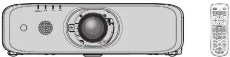
natural_image
Illustration of a projector with front panel and remote control (no text or symbols)
Thank you for purchasing this Panasonic product.
■ This manual is common to all the models regardless of suffixes of the Model No.
- for Taiwan
T: The standard zoom lens supplied
- for India
D: The standard zoom lens supplied
● for Asia (except for Taiwan, India, Korea)
A: The standard zoom lens supplied LA: The lens sold separately
● for other countries or regions
Without L: The standard zoom lens supplied With L: The lens sold separately
■ Before operating this product, please read the instructions carefully and save this manual for future use.
■ Before using this product, be sure to read "Read this first" (pages 4 to 13).
Contents
Read this first! 4
Chapter 1 Preparation
Precautions for use....17
Lens cushion 17
Cautions when transporting....17
Cautions when installing....17
Security 19
DIGITAL LINK....19
Notes on Using Wireless Connection....20
Early Warning Software....21
Cautions on use 21
Disposal....22
Accessories 23
Optional accessories....24
About your projector....25
Remote control 25
Projector body 26
Preparing the remote control 29
Inserting and removing the batteries 29
When using the system with multiple projectors .. 29
Connecting the remote control to the projector with a cable 29
Chapter 2 Getting Started
Setting up....31
Installation mode 31
Parts for ceiling mount (optional)....31
Projected image and throw distance 32
Adjusting adjustable feet 37
Removing/attaching the projection lens 38
Removing the projection lens 38
Attaching the projection lens 38
Connecting....40
Before connecting 40
Connecting example: AV equipment 41
Connecting example: Computers 42
Connecting example using DIGITAL LINK ...... 42
Chapter 3 Basic Operations
Switching on/off the projector....45
Connecting the power cord 45
Power indicator....45
Switching on the projector 46
When the initial setting screen is displayed......47
Making adjustments and selections 49
Switching off the projector 50
Direct power off function....50
Projecting....51
Selecting the input signal 51
Adjusting the focus, zoom and shift....52
Moving the lens to the home position....53
Adjustment range by the lens position shift (optical axis shift)....53
Operating with the remote control....54
Using the shutter/AV mute function 54
Using the mute function....55
Adjusting the volume 55
Using the freeze function....55
Using the on-screen display function 55
Using the automatic setup function 56
Using the SCREEN ADJ button....56
Switching the aspect ratio of the image....57
Using the digital zoom function 57
Using the presentation timer function....58
Using the FUNCTION button....58
Displaying internal test patterns 58
Using the status function 59
Using the ECO management function....59
Setting the ID number of the remote control ..... 59
Chapter 4 Settings
Navigating through the menu 62
Main menu....63
Sub-menu....63
[PICTURE MODE]......66
[CONTRAST]......66
[BRIGHTNESS] 66
[COLOR]......67
[TINT] 67
[SHARPNESS] 67
[COLOR TEMPERATURE]......67
[GAMMA]....68
[IRIS] 68
[ADVANCED MENU] 68
[DAYLIGHT VIEW]......69
[DIGITAL CINEMA REALITY] 69
[NOISE REDUCTION]......69
[TV-SYSTEM]....70
[RGB / YPBP R] / [RGB / YCBC R] 70
[POSITION] menu 71
[REALTIME KEYSTONE]....71
[SCREEN ADJUSTMENT] (For PT-EZ590)....71
[SCREEN ADJUSTMENT] (For PT-EW650, PT-EW550, PT-EX620 and PT-EX520)....75
[SHIFT]....77
[DOT CLOCK]....77
[CLOCK PHASE]....78
[OVER SCAN]....78
[ASPECT]....78
[FRAME LOCK]....79
[CLAMP POSITION]....79
[LANGUAGE] menu....80
Changing the display language 80
[DISPLAY OPTION] menu....81
[ON-SCREEN DISPLAY]......81
[RGB IN] 82
[HDMI IN]......83
[DIGITAL LINK IN] 84
[CLOSED CAPTION SETTING] (Only for NTSC, 480i YC B C R input)....85
[SCREEN SETTING]......86
[STARTUP LOGO]......87
[SHUTTER SETTING]......87
[AUTO SETUP SETTING] 88
[SIGNAL SEARCH] 88
[STARTUP INPUT SELECT] 88
[BACK COLOR]......89
[WIDE MODE] 89
[SXGA MODE]......89
[P-TIMER]......89
[OTHER FUNCTIONS]......90
[PROJECTOR SETUP] menu 92
[STATUS]....92
[PROJECTOR ID]......92
[INITIAL START UP]....92
[PROJECTION METHOD]......93
[LAMP POWER] 93
[ECO MANAGEMENT]......93
[RS-232C]....95
[REMOTE1 MODE] 96
[FUNCTION BUTTON]....96
[AUDIO SETTING] 97
[TEST PATTERN]....99
[FILTER COUNTER]......99
[SCHEDULE]....100
[DATE AND TIME] 102
[LENS CALIBRATION] 102
[INITIALIZE ALL] 103
[SERVICE PASSWORD]......103
[SECURITY] menu 104
[PASSWORD]....104
[PASSWORD CHANGE] 104
[DISPLAY SETTING]....104
[TEXT CHANGE]....105
[MENU LOCK]....105
[MENU LOCK PASSWORD] 105
[CONTROL DEVICE SETUP]......105
[NETWORK] menu....107
[ DIGITAL LINK MODE]......107
[DIGITAL LINK STATUS]....107
[ DIGITAL LINK MENU ] ...... 108
[WIRED LAN] 108
[PROJECTOR NAME]......108
[NETWORK CONTROL] 109
[NETWROK STATUS] 109
[INITIALIZE] 110
Chapter 5 Operation of Function
Network connections 112
When connecting via wired LAN 112
When connecting via wireless LAN 114
About Presenter Light.... 116
About VueMagic 118
Web control function.... 119
Accessing from the web browser 119
Chapter 6 Maintenance
Lamp/temperature/filter indicators 136
When an indicator lights up 136
Maintenance/replacement.... 138
Before performing maintenance/replacement .... 138
Maintenance....138
Replacing the unit....141
Troubleshooting 144
Chapter 7 Appendix
Technical information 147
PJLink protocol....147
Control commands via LAN....148
terminal 151
terminal 154
[MENU LOCK PASSWORD] operations ..... 155
List of compatible signals 156
Specifications 158
Dimensions 161
Precautions for Attaching Ceiling
Mount Bracket 162
Index 163
Read this first!
WARNING: THIS APPARATUS MUST BE EARTHED.
WARNING: To prevent damage which may result in fire or shock hazard, do not expose this appliance to rain or moisture.
This device is not intended for use in the direct field of view at visual display workplaces. To avoid accommodating reflexions at visual display workplaces this device must not be placed in the direct field of view.
The equipment is not intended for used at a video workstation in compliance BildscharbV.
The sound pressure level at the operator position is equal or less than 70 dB (A) according to ISO 7779.
WARNING:
Remove the plug from the mains socket when this unit is not in use for a prolonged period of time.
To prevent electric shock, do not remove cover. No user serviceable parts inside. Refer servicing to qualified service personnel.
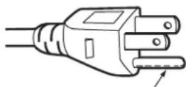
Do not remove the earthing pin on the mains plug. This apparatus is equipped with a three prong earthing-type mains plug. This plug will only fit an earthing-type mains socket. This is a safety feature. If you are unable to insert the plug into the mains socket, contact an electrician. Do not defeat the purpose of the earthing plug.
WARNING:
This equipment is compliant with Class A of CISPR32.
In a residential environment this equipment may cause radio interference.
WARNING: TO REDUCE THE RISK OF FIRE OR ELECTRIC SHOCK, DO NOT EXPOSE THIS PRODUCT TO RAIN OR MOISTURE.
WARNING: RISK OF ELECTRIC SHOCK. DON'T OPEN
AVERTISSEMENT:RISQUE DE CHOC ÉLECTRIQUE. NE PAS OUVRIR.
WARNUNG:ZUR VERMEIDUNG EINES ELEKTRISCHEN SCHLAGES GERÄT NICHT ÖFFNEN.
ПРЕДУПРЕЖДЕНИЕ:ОПАСНОСТЬ ПОРАЖЕНИЯ ЭЛЕКТРИЧЕСКИМ ТОКОМ. НЕ ОТКРЫВАТЬ.
경고:길전 위험미 있으므로 열지마십시오.
Indicated on the projector
The lightning flash with arrowhead symbol, within an equilateral triangle, is intended to alert the user to the presence of uninsulated “dangerous voltage” within the product’s enclosure that may be of sufficient magnitude to constitute a risk of electric shock to persons.
The exclamation point within an equilateral triangle is intended to alert the user to the presence of important operating and maintenance (servicing) instructions in the literature accompanying the product.
WARNING: TURN THE POWER OFF AND DISCONNECT THE POWER PLUG FROM THE WALL OUTLET BEFORE REPLACING THE LAMP UNIT.
CAUTION: To assure continued compliance, follow the attached installation instructions. This includes using the provided power cord and shielded interface cables when connecting to computer or peripheral devices. Also, any unauthorized changes or modifications to this equipment could void the user's authority to operate this device.
This is a device to project images onto a screen, etc., and is not intended for use as indoor lighting in a domestic environment.
Directive 2009/125/EC
Importer's name and address within the European Union
Panasonic Marketing Europe GmbH
Panasonic Testing Centre
Winsbergring 11, 22525 Hamburg, Germany
CAUTION (North/Middle/South America)
Power Supply: This Projector is designed to operate on 100 V - 240 V, 50 Hz/60 Hz AC, house current only.
CAUTION: The AC power cord which is supplied with the projector as an accessory can only be used for power supplies up to 125 V. If you need to use higher voltages than this, you will need to obtain a separate 250 V power cord. If you use the accessory cord in such situations, fire may result.
CAUTION (North/Middle/South America/Taiwan)
This equipment is equipped with a three-pin grounding-type power plug. Do not remove the grounding pin on the power plug. This plug will only fit a grounding-type power outlet. This is a safety feature. If you are unable to insert the plug into the outlet, contact an electrician. Do not defeat the purpose of the grounding plug.
WARNING (USA and Canada)
Not for use in a computer room as defined in the Standard for the Protection of Electronic Computer/Data Processing Equipment, ANSI/NFPA 75.
For permanently connected equipment, a readily accessible disconnect device shall be incorporated in the building installation wiring.
For pluggable equipment, the socket-outlet shall be installed near the equipment and shall be easily accessible.
NOTICE USA only:
- This product has a High Intensity Discharge (HID) lamp that contains mercury. Disposal may be regulated in your community due to environmental considerations. For disposal or recycling information, please visit Panasonic website: http://www.panasonic.com/environmental or call 1-888-769-0149.
For USA-California Only
This product contains a CR Coin Cell Lithium Battery which contains Perchlorate Material – special handling may apply.
See www.dtsc.ca.gov/hazardouswaste/perchlorate
NOTIFICATION (Canada)
This class A digital apparatus complies with Canadian ICES-003.
For more information on safe handling procedures, the measures to be taken in case of accidental breakage and safe disposal options visit: ec.gc.ca/mercury-mercury/.
Dispose of or recycle in accordance with applicable laws.
Trade Name: Panasonic
Responsible Party: Panasonic Corporation of North America
Address: Two Riverfront Plaza, Newark, NJ 07102-5490
General Contact: http://www.panasonic.com/support
Projector Contact: http://panasonic.net/avc/projector/
This device complies with Part 15 of the FCC Rules. Operation is subject to the following two conditions: (1) This device may not cause harmful interference, and (2) this device must accept any interference received, including interference that may cause undesired operation.
Caution:
This equipment has been tested and found to comply with the limits for a Class A digital device, pursuant to part 15 of the FCC Rules. These limits are designed to provide reasonable protection against harmful interference when the equipment is operated in a commercial environment. This equipment generates, uses, and can radiate radio frequency energy and, if not installed and used in accordance with the instruction manual, may cause harmful interference to radio communications. Operation of this equipment in a residential area is likely to cause harmful interference in which case the user will be required to correct the interference at his own expense.
FCC Warning:
To assure continued compliance, follow the attached installation instructions. This includes using the provided power cord and shielded interface cables when connecting to computer or peripheral devices. Also, any unauthorized changes or modifications to this equipment could void the user's authority to operate this device.
IMPORTANT: THE MOULDED PLUG
FOR YOUR SAFETY, PLEASE READ THE FOLLOWING TEXT CAREFULLY.
This appliance is supplied with a moulded three pin mains plug for your safety and convenience. A 13 amp fuse is fitted in this plug. Should the fuse need to be replaced, please ensure that the replacement fuse has a rating of 13 amps and that it is approved by ASTA or BSI to BS1362.
Check for the ASTA mark 📂 or the BSI mark 🤘 on the body of the fuse.
If the plug contains a removable fuse cover, you must ensure that it is refitted when the fuse is replaced. If you lose the fuse cover, the plug must not be used until a replacement cover is obtained. A replacement fuse cover can be purchased from an Authorised Service Center.
If the fitted moulded plug is unsuitable for the mains socket in your home, then the fuse should be removed and the plug cut off and disposed of safely. There is a danger of severe electrical shock if the cut off plug is inserted into any 13 amp socket.
If a new plug is to be fitted, please observe the wiring code as shown below. If in any doubt, please consult a qualified electrician.
WARNING: THIS APPLIANCE MUST BE EARTHED.
IMPORTANT: The wires in this mains lead are coloured in accordance with the following code:
Green - and - Yellow: Earth
Blue: Neutral
Brown: Live
As the colours of the wire in the mains lead of this appliance may not correspond with the coloured markings identifying the terminals in your plug, proceed as follows.
The wire which is coloured GREEN - AND - YELLOW must be connected to the terminal in the plug which is marked with the letter E or by the Earth symbol 12 or coloured GREEN or GREEN - AND - YELLOW.
The wire which is coloured BLUE must be connected to the terminal in the plug which is marked with the letter N or coloured BLACK.
The wire which is coloured BROWN must be connected to the terminal in the plug which is marked with the letter L or coloured RED.
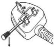
How to replace the fuse: Open the fuse compartment with a screwdriver and replace the fuse.
For PT-EZ590A / PT-EW650A / PT-EW550A / PT-EX620A / PT-EX520A series
CE
This equipment is in compliance with the essential requirements and other relevant provisions of Directive 1999/5/EC.
Customers can download a copy of the original DoC for this product from our DoC server:
http://www.ptc.panasonic.de
Contact in the EU: Panasonic Marketing Europe GmbH, Panasonic Testing Centre, Winsbergring 11, 22525
Hamburg, Germany
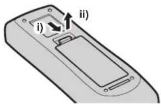
To remove the battery
Remote Control Battery
1. Press the guide and lift the cover.
text_image
i)
ii)
2. Remove the batteries.
natural_image
Diagram of a remote control panel with arrows indicating internal components (no text or symbols)
Brazil Only
Brasil Apenas
2. Remova as baterias.
natural_image
Diagram of a remote control panel with arrows indicating internal components (no text or symbols)
WARNING:
POWER
The wall outlet or the circuit breaker shall be installed near the equipment and shall be easily accessible when problems occur. If the following problems occur, cut off the power supply immediately.
Continued use of the projector in these conditions will result in fire or electric shock.
If foreign objects or water get inside the projector, cut off the power supply.
If the projector is dropped or the cabinet is broken, cut off the power supply.
If you notice smoke, strange smells or noise coming from the projector, cut off the power supply.
During a thunderstorm, do not touch the projector or the cable.
Electric shocks can result.
Do not do anything that might damage the power cord or the power plug.
If the power cord is used while damaged, electric shocks, short-circuits or fire will result.
Do not damage the power cord, make any modifications to it, place it near any hot objects, bend it excessively, twist it, pull it, place heavy objects on top of it or wrap it into a bundle.
Completely insert the power plug into the wall outlet and the power connector into the projector terminal.
If the plug is not inserted correctly, electric shocks or overheating will result.
- Do not use plugs which are damaged or wall outlets which are coming loose from the wall.
Do not use anything other than the provided power cord.
Failure to observe this will result in electric shocks or fire. Please note that if you do not use the provided power cord to ground the device on the side of the outlet, this may result in electric shocks.
Clean the power plug regularly to prevent it from becoming covered in dust.
Failure to observe this will cause a fire.
If dust builds up on the power plug, the resulting humidity can damage the insulation.
If not using the projector for an extended period of time, pull the power plug out from the wall outlet.
Do not handle the power plug and power connector with wet hands.
Failure to observe this will result in electric shocks.
Do not overload the wall outlet.
If the power supply is overloaded (ex., by using too many adapters), overheating may occur and fire will result.
■ ON USE/INSTALLATION
Do not place the projector on soft materials such as carpets or sponge mats.
Doing so will cause the projector to overheat, which can cause burns, fire or damage to the projector.
Do not set up the projector in humid or dusty places or in places where the projector may come into contact with oily smoke or steam.
Using the projector under such conditions will result in fire, electric shocks or deterioration of components. Deterioration of components (such as ceiling mount brackets) may cause the projector which is mounted on the ceiling to fall down.
Do not install this projector in a place which is not strong enough to take the full weight of the projector or on top of a surface which is sloped or unstable.
Failure to observe this will cause projector to fall down or tip over the projector, and severe injury or damage could result.
WARNING:
Do not cover the air intake/exhaust ports.
Doing so will cause the projector to overheat, which can cause fire or damage to the projector.
Do not place the projector in narrow, badly ventilated places.
Do not place the projector on cloth or papers, as these materials could be drawn into the air intake port.
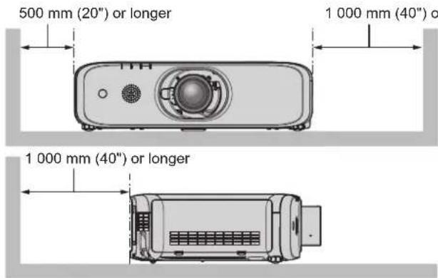
Provide at least 1 m (40") of space between any walls or objects and the exhaust port, and at least 50 cm (20") of space between any walls or objects and the intake port.
Do not place your hands or other objects close to the air exhaust port.
Doing so will cause burns or damage your hands or other objects.
- Heated air comes out of the air exhaust port. Do not place your hands or face, or objects which cannot withstand heat close to this port.
Do not look at or place your skin into the light emitted from the lens while the projector is being used.
Doing so can cause burns or loss of sight.
Strong light is emitted from the projector's lens. Do not look at or place your hands directly into this light.
Be especially careful not to let young children look into the lens. In addition, turn off the power and switch off the main power when you are away from the projector.
Never attempt to remodel or disassemble the projector.
High voltages can cause fire or electric shocks.
- For any inspection, adjustment and repair work, please contact an Authorized Service Center.
Do not project an image with the lens cover attached.
Doing so can cause fire.
Doing so may cause short circuits or overheating, and result in fire, electric shock, or malfunction of the projector.
Do not place containers of liquid or metal objects near the projector.
If liquid enters inside of the projector, consult your dealer.
Particular attention must be paid to children.
Use the ceiling mount bracket specified by Panasonic.
Using the ceiling mount bracket other than the specified one will result in falling accidents.
- Attach the supplied safety cable to the ceiling mount bracket to prevent the projector from falling down.
Installation work (such as ceiling mount bracket) should only be carried out by a qualified technician.
If installation is not carried out and secured correctly, it can cause injury or accidents, such as electric shocks.
- Be sure to use the wire provided with the ceiling mount bracket as an extra safety measure to prevent the projector from falling down. (Install in a different location to the ceiling mount bracket.)
ACCESSORIES
Do not use or handle the batteries improperly, and refer to the following.
Failure to observe this will cause burns, batteries to leak, overheat, explode or catch fire.
Do not use unspecified batteries.
Do not use chargeable batteries.
Do not disassemble dry cell batteries.
Do not heat the batteries or place them into water or fire.
Do not allow the + and – terminals of the batteries to come into contact with metallic objects such as necklaces or hairpins.
Do not store or carry batteries together with metallic objects.
Store the batteries in a plastic bag and keep them away from metallic objects.
Make sure the polarities (+ and −) are correct when inserting the batteries.
Do not use a new battery together with an old battery or mix different types of batteries.
Do not use batteries with the outer cover peeling away or removed.
WARNING:
If the battery fluid leaks, do not touch it with bare hands, and take the following measures if necessary.
Battery fluid on your skin or clothing could result in skin inflammation or injury.
Battery fluid coming in contact with your eyes could result in loss of sight.
Do not remove unspecified screws during the lamp unit replacement.
Doing so can cause electric shocks, burns, or injury.
Do not disassemble the lamp unit.
If the lamp breaks, it could cause injury.
Lamp replacement
The lamp has high internal pressure. If improperly handled, an explosion and severe injury or accidents will result.
The lamp can easily explode if struck against hard objects or dropped.
Before replacing the lamp unit, be sure to turn the power off and to disconnect the power plug from the wall outlet.
When replacing the lamp unit, turn the power off and allow the lamp to cool for at least one hour before handling it otherwise it can cause burns.
Do not use the supplied power cord with devices other than this projector.
- Using the supplied power cord with devices other than this projector may cause short circuits or overheating, and result in electric shock or fire.
Do not allow children to reach the batteries and the lens release button fixing screw.
Accidentally swallowing them can cause physical harm.
- If swallowed, seek medical advice immediately.
Remove the depleted batteries from the remote control promptly.
• Leaving them in the unit may result in fluid leakage, overheating, or explosion of the batteries.
CAUTION:
POWER
When disconnecting the power cord, be sure to hold the power plug and the power connector.
If the power cord itself is pulled, the lead will become damaged, and fire, short-circuits or serious electric shocks will result.
When not using the projector for an extended period of time, disconnect the power plug from the wall outlet.
Failure to do so may result in fire or electric shock.
Before replacing the projection lens, be sure to turn off the power and disconnect the power plug from the wall outlet.
Unexpected projection of light may cause injury to eyes.
Replacing the projection lens without removing the power plug may result in electric shock.
Disconnect the power plug from the wall outlet before carrying out any cleaning and replacing the unit. Failure to do so may result in electric shock.
■ ON USE/INSTALLATION
Do not place heavy objects on top of the projector.
Failure to observe this will cause the projector to become unbalanced and fall, which could result in damage or injury. The projector will be damaged or deformed.
Do not put your weight on this projector.
You could fall or the projector could break, and injury will result.
- Be especially careful not to let young children stand or sit on the projector.
Do not place the projector in extremely hot locations.
Doing so will cause the outer casing or internal components to deteriorate, or result in fire.
• Take particular care in locations exposed to direct sunlight or near heaters.
Do not install the projector in a location where salt pollution or corrosive gas may occur.
Doing so may result in falling due to corrosion. Also, it may result in malfunctions.
Do not place your hands in the openings beside the optical lens, while shifting the lens.
Failure to observe this could cause injury.
Do not place objects in front of the lens while the projector is being used.
Doing so can cause fire, damage to an object, or malfunction of the projector.
- Extremely strong light is emitted from the projector's lens.
Do not stand in front of the lens while the projector is being used.
Doing so can cause damage and burns to clothing.
- Extremely strong light is emitted from the projector's lens.
Always disconnect all cables before moving the projector.
Moving the projector with cables still attached can damage the cables, which will cause fire or electric shocks to occur.
When mounting the projector on the ceiling, keep mounting screws and power cord from contact with metal parts inside the ceiling.
Contact with metal parts inside the ceiling can cause electric shocks.
Never plug headphones and earphones into terminal.
Excessive sound pressure from earphones and headphones can cause hearing loss.
ACCESSORIES
Do not use the old lamp unit.
If used it could cause lamp explosion.
If the lamp has broken, ventilate the room immediately. Do not touch or bring your face close to the broken pieces.
Failure to observe this will cause the user to absorb the gas which was released when the lamp broke and which contains nearly the same amount of mercury as fluorescent lamps, and the broken pieces will cause injury.
If you believe that you have absorbed the gas or that the gas has got into your eyes or mouth, seek medical advice immediately.
Ask your dealer about replacing the lamp unit and check the inside of the projector.
CAUTION:
When not using the projector for an extended period of time, remove the batteries from the remote control.
Failure to observe this will cause the batteries to leak, overheat, catch fire or explode, which may result in fire or contamination of surrounding area.
MAINTENANCE
Do not attach the air filter unit while it is wet.
Doing so may result in electric shock or malfunctions.
- After you clean the air filter units, dry them thoroughly before reattaching them.
Ask your dealer about cleaning inside the projector once a year.
Continuous use while dust is accumulated inside the projector may result in fire.
- For cleaning fee, ask your dealer.
Trademarks
Windows and Internet Explorer are registered trademarks or trademarks of Microsoft Corporation in the United States and other countries.
Mac, Mac OS, OS X, iPad, iPhone, iPod touch and Safari are trademarks of Apple Inc., registered in the United States and other countries.
IOS is a trademark and registered trademark of Cisco in the United States and other countries and is used under license.
VueMagic is a trademark of Pixelworks, Inc.
PJLink™ is a registered trademark or pending trademark in Japan, the United States and other countries and regions.
HDMI, the HDMI Logo and High-Definition Multimedia Interface are trademarks or registered trademarks of HDMI Licensing LLC in the United States and other countries.
RoomView and Crestron RoomView are registered trademarks of Crestron Electronics, Inc. Crestron Connected™ and Fusion RV are trademarks of Crestron Electronics, Inc.
HDBaseT™ is a trademark of HDBaseT Alliance.
Adobe, Adobe Flash Player and Adobe Reader are trademarks or registered trademarks of Adobe Systems Inc. in the United States and/or other countries.
Some of the fonts used in the on-screen menu are Ricoh bitmap fonts, which are manufactured and sold by Ricoh Company, Ltd.
All other names, company names and product names mentioned in this manual are trademarks or registered trademarks of their respective owners.
This product incorporates the following software.
(1) The software which is developed independently by or for Panasonic Corporation
The software categorized as (3) \~ (5), the license is available in accordance with gnu general public license and gnu lesser general public license respectively, it is distributed in the hope that it will be useful, but without any warranty, without even the implied warranty of merchantability or fitness for a particular purpose. As for the terms and conditions, please refer to the software license of the supplied CD-ROM.
If you wish to ask any questions as to the software, please contact (sav.pj.gpl.pavc@ml.jp.panasonic.com) by email.
■Illustrations in this manual
Illustrations of the projector, screen, and other parts may vary from the actual product.
Pictures shown are illustrations of PT-EZ590 in this manual, other models have their own characteristics and may be different from them.
■Reference pages
- Reference pages in this manual are indicated as (→ page 00).
Term
- In this manual, the "Wireless/wired remote control unit" accessory is referred to as "Remote control".
Features of the Projector
Quick Steps
For details, refer to the corresponding pages.
High luminance and high contrast ^2
▶ A high luminated a high contrast ^2 (Except for PT-EW550, PT-EX520) are achieved by means of a unique optical system and lamp drive system.
*1 PT-EX620 is 6 200 lm, PT-EW650 is 5 800 lm, PT-EZ590 is 5 400 lm, PT-EX520 is 5 300 lm and PT-EW550 is 5 000 lm.
Easy and highly flexible setup
▶ Easy and highly flexible setup is achieved by an electric lens shift function, and a lineup of various optional lenses.
Reduced maintenance costs
▶ New lamp driving system and long life filter have greatly improved the recommended time to replace the lamp and filter, so you can reduce the maintenance cost.
[Reference]
Lamp: 4 000 Hours ([LAMP POWER] is set to [NORMAL])
5 000 Hours ([LAMP POWER] is set to [ECO])
Set up the projector.
(→ page 31)
Attach the projection lens.
(→ page 38)
Connect with external devices.
(→ page 40)
Connect the power cord.
(→ page 45)
Switch on the projector.
(→ page 46)
Make initial settings.
(→ page 47)
- Take this step when you switch on the power for the first time after purchasing the projector.
Select the input signal.
(→ page 51)
Adjust the image.
(→ page 52)
Chapter 1 Preparation
This chapter describes things you need to know or check before using the projector.
Precautions for use
Lens cushion
(Only for the projector purchased with the standard zoom lens)
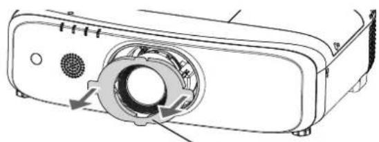
- In order to protect the projection lens from the vibration during transportation, lens cushion is attached to the product at the time of purchase. Please remove the lens cushion before use.
natural_image
Diagram of a projector with a circular housing and ventilation slots (no text or symbols)
Lens cushion
Cautions when transporting
When transporting the projector, hold it securely by its bottom and avoid excessive vibration and impacts. They may damage the internal components and result in malfunctions.
Do not transport the projector with the adjustable feet extended. Doing so may damage the adjustable feet.
Do not move or transport the projector with the wireless module (Model No.: ET-WML100) of the optional accessories attached. Doing so may damage the wireless module.
Cautions when installing
■Do not set up the projector outdoors.
The projector is designed for indoor use only.
■Do not set up the projector in the following locations.
Places where vibration and impacts occur such as in a car or vehicle: Doing so may cause damage to internal components or malfunction.
Locations near the sea or areas affected by corrosive gas: Corrosion may damage internal components or cause the projector to malfunction.
Near the exhaust of an air conditioner: Depending on the conditions of use, the screen may fluctuate in rare cases due to the heated air from the air exhaust port or the hot or cooled air. Make sure that the exhaust from the projector or other equipment, or the air from the air conditioner does not blow toward the front of the projector.
Near high-voltage power lines or near motors: Doing so may interfere with the operation of the projector.
Places with sharp temperature fluctuations such as near lights (studio lamps): Doing so may shorten the life of the lamp, or result in deformation of the outer case due to heat, which may cause malfunctions. Follow the operating environment temperature of the projector.
■ Be sure to ask a specialized technician or your dealer when installing the projector on a ceiling.
The optional Ceiling Mount Bracket is required. Be sure to use the Projector Mount Bracket together with the ceiling mount bracket for high ceilings or low ceilings.
Model No.:
① ET-PKD120H (for High Ceilings), ET-PKE300B (Projector Mount Bracket)
■ Ask a qualified technician or your dealer to install the cable wiring for DIGITAL LINK connection.
(Only for PT-EZ590, PT-EW650 and PT-EX620)
Image and sound may be disrupted if cable transmission characteristics cannot be obtained due to inadequate installation.
■ The projector may not work properly due to strong radio waves from the broadcast station or the radio.
(Only for PT-EZ590, PT-EW650 and PT-EX620)
If there is any facility or equipment, which outputs strong radio waves, near the installation location, install the projector at a location sufficiently far from the source of the radio waves. Or, wrap the LAN cable connected to the terminal by using a piece of metal foil or a metal pipe which is grounded at both ends.
■ Focus adjustment
The projection lens is thermally affected by the light from the light source, making the focus unstable in the period just after switching on the power. It is recommended that images be projected continuously for at least 30 minutes before the focus is adjusted.
■ Do not install the projector at elevations of 2 700 m (8 858') or higher above sea level.
■ Do not use the projector in a location that the ambient temperature exceeds 45 °C (113 °F).
Using the projector in a location that the altitude is too high or the ambient temperature is too high may reduce the life of the components or result in malfunctions.
The upper limit of the operating environment temperature should be between 0 °C (32 °F) and 45 °C (113 °F) when using it at elevations lower than 1 400 m (4 593') above sea level, and between 0 °C (32 °F) and 40 °C (104 °F) when using it at high altitudes (between 1 400 m (4 593') and 2 700 m (8 858') above sea level).
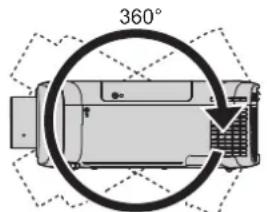
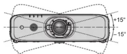
■Do not use the projector tilted to the right or left.
Using the projector at an angle that exceeds ±15^ from the horizontal plane may reduce product life or result in malfunction.
text_image
360°
Vertical 360°
text_image
+15°
-15°
■Cautions when setting up the projector
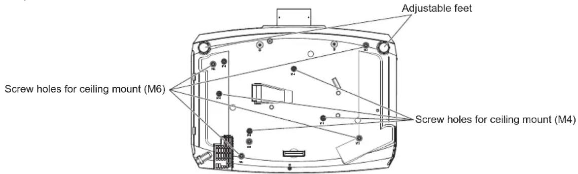
Use the adjustable feet only for the floor standing installation and for adjusting the angle. Using them for other purposes may damage the projector.
When installing and using the projector with a method other than the floor standing installation using the adjustable feet or the ceiling mount, please fix the projector by using the four screw holes with "M6" mark for ceiling mount (as shown in the figure).
(Screw diameter: M6, tapping depth inside the set: 12 mm (15/32"), torque: 4 ± 0.5 N·m)
Also at that time, make sure that there is no clearance between the screw holes for ceiling mount on the projector bottom and the setting surface by inserting spacers (metallic) between them.
When using the existing ceiling mount bracket (for high ceilings) ET-PKF110H or the existing ceiling mount bracket (for low ceilings) ET-PKF110S, you can use the four screw holes with "M4" mark (as shown in the figure), but do not use these holes for other than ceiling mount. (→ page 162)
(Screw diameter: M4, tapping depth inside the set: 8 mm (5/16"), torque: 1.25 ± 0.2 N·m)
In addition, do not mix the M4 and M6 screw holes for installation.
text_image
Adjustable feet
Screw holes for ceiling mount (M6)
Screw holes for ceiling mount (M4)
The positions of screw holes for ceiling mount and adjustable feet
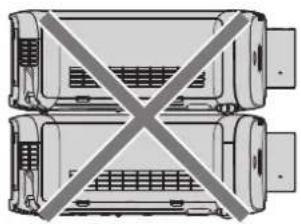
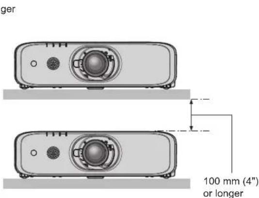
Do not stack projectors on top of each other.
Do not use the projector supporting it by the top.
Do not block the ventilation ports (intake and exhaust) of the projector.
Prevent hot and cool air from the air conditioning system to blow directly to the ventilation ports (intake and exhaust) of the projector.
natural_image
Diagram of two vehicle chassis with diagonal crossed lines indicating crossed-out or no crossing (no text or symbols)
natural_image
Exterior view of an electric motor with a diagonal line crossing through it (no text or symbols)
text_image
500 mm (20") or longer
1 000 mm (40")
1 000 mm (40") or longer
text_image
ger
100 mm (4")
or longer
- Do not install the projector in a confined space.
When installing the projector in a confined space, provide air conditioning or ventilation separately. Exhaust heat may accumulate when the ventilation is not enough, triggering the protection circuit of the projector.
Security
When using this product, take safety measures against the following incidents.
• Personal information being leaked via this product
DIGITAL LINK
(Only for PT-EZ590, PT-EW650 and PT-EX620)
"DIGITAL LINK" is a technology to transmit the video, audio, Ethernet, and serial control signals using a twisted pair cable by adding unique functions by Panasonic to the HDBaseT™ communication standard formulated by HDBaseT Alliance.
This projector supports the optional Panasonic DIGITAL LINK output supported device (Model No.: ET-YFB100G, ET-YFB200G) and peripheral devices by other manufacturers (twisted-pair-cable transmitters such as the "XTP transmitter" of Extron Electronics) that use the same HDBaseT™ standard. For the devices of other manufacturers that the operation has been verified with this projector, refer to Panasonic website (http://panasonic.net/avc/projector/). Note that the verification for devices of other manufacturers has been made for the items set by Panasonic Corporation, and not all the operations have been verified. For operation or performance problems caused by the devices of other manufacturers, contact the respective manufacturers. In addition, the projector does not support audio transmission because it is not equipped with audio function.
Notes on Using Wireless Connection
Wireless connection function of the projector uses radio waves in the 2.4 GHz band.
A radio station license is not required, but be sure to read and fully understand the following items before use.
The wireless module (Model No.: ET-WML100) of optional accessories must be installed when you want to use the wireless LAN function of this projector.
■Do not use near other wireless equipment.
The following equipment may use radio waves in the same band as the projector.
When the projector is used near these devices, radio wave interference may make communication impossible, or the communication speed may become slower.
Microwave ovens, etc.
Industrial, chemical and medical equipment, etc.
In-plant radio stations for identifying moving objects such as those used in factory manufacturing lines, etc.
Designated low-power radio stations.
■ If at all possible, avoid the use of cellular phones, TV sets or radios near the projector.
Cellular phones, TV sets, radios and similar devices use different radio bands from the projector, so there is no effect on wireless communication or the transmission and reception of these devices. However, radio waves from the projector may produce audio or video noise.
Communication is possible through walls and floors made from materials such as wood and glass (except glass containing wire mesh), but not through walls and floors made from steel reinforcements, metal, concrete, etc.
■ Avoid using the projector in locations prone to static electricity.
If the projector is used in a location prone to static electricity, such as on a carpet, the wireless LAN or wired LAN connection may be lost.
If the static electricity or noise make it impossible to establish a connection with the LAN, please press the power button on the remote control or the control panel to power off the projector, and eliminate the source of static electricity or noise, then turn on the projector.
■Using the projector outside the country
Note that depending on countries or regions there are restrictions on the channels and frequencies at which you can use the wireless LAN.
■Available wireless LAN channels
The channels (frequency range) that can be used differ according to the country or region. Refer to the table below.
Country or region Standard Channels used Frequency band (Center frequency) Global IEEE802.11b/g/n 1 - 11 channel 2.412 GHz - 2.462 GHz
* The frequency and channel differ depending on the country.
Note
- The wireless module (Model No.: ET-WML100) of the optional accessories is required if you want to use the wireless LAN function of this projector.
About Wireless LANs
The advantage of a wireless LAN is that information can be exchanged between a PC or other such equipment and an access point using radio waves as long as you are within range for radio transmissions.
On the other hand, because the radio waves can travel through obstacles (such as walls) and are available everywhere within a given range, problems of the type listed below may occur if security-related settings are not made.
A malicious third-part may intentionally intercept and monitor transmitted data including the content of e-mail and personal information such as your ID, password, and/or credit card numbers.
A malicious third-party may access your personal or corporate network without authorization and engage in the following types of behavior.
Retrieve personal and/or secret information (information leak)
Spread false information by impersonating a particular person (spoofing)
Overwrite intercepted communications and issue false data (tampering)
Spread harmful software such as a computer virus and crash your data and/or system (system crash)
Since most wireless LAN adapters or access points are equipped with security features to take care of these problems, you can reduce the possibility of these problems occurring when using this product by making the appropriate security settings for the wireless LAN device.
Some wireless LAN devices may not be set for security immediately after purchase. To decrease the possibility of occurrence of security problems, before using any wireless LAN devices, be absolutely sure to make all security-related settings according to the instructions given in the operation manuals supplied with them.
Depending on the specifications of the wireless LAN, a malicious third-party may be able to break security settings by special means.
Panasonic asks customers to thoroughly understand the risk of using this product without making security settings, and recommends that the customer make security settings at their own discretion and responsibility.
Early Warning Software
The projector supports “Early Warning Software”, which monitors the status of the display (projector and flat panel display) and the peripheral devices inside an intranet, and notifies of abnormality of such equipment and detects signs of possible abnormality. Also, maintenance can be performed in advance, because this software gives notification of approximate time to replace consumables of the display, to clean each part of the display, and to replace the components of the display.
Depending on the type of license, the number of displays that can be registered for monitoring varies. Limited to the first 90 days after installation in a computer, it is possible to register up to 2048 units of displays free of charge. Download the software from Panasonic website (http://panasonic.net/avc/projector/pass/). It is necessary to register and login to PASS ^1 to download.
*1 PASS: Panasonic Professional Display and Projector Technical Support Website
Refer to Panasonic website (http://panasonic.net/avc/projector/pass/) for details.
Cautions on use
■To get a good picture quality
- In order to view a beautiful image in higher contrast, prepare an appropriate environment. Draw curtains or blinds over windows and turn off any lights near the screen to prevent outside light or light from indoor lamps from shining onto the screen.
■ Do not touch the surface of the projection lens with your bare hands.
If the surface of the projection lens becomes dirty from fingerprints or anything else, this will be magnified and projected onto the screen.
Attach the lens cover supplied with the projector or with the optional projection lens to the projector when you do not use the projector.
■LCD panel
- The LCD panel is precision-made. Note that in rare cases, pixels of high precision could be missing or always lit. Note that such phenomena do not indicate malfunction. If still images are projected for a long time, a residual image may remain on the LCD panel. Note that the residual image may not disappear.
■Optical parts
When the operating environment temperature is high or in environments where lots of dust, cigarette smoke, etc. is present, the replacement cycle of the LCD panel, polarizing plates and other optical parts may be shorter even if used for less than one year. Consult your dealer for details.
■ Do not move the projector or subject it to vibration or impact while it is operating.
Doing so may shorten the life of the built-in motor.
Lamp
The light source of the projector is a high-pressure mercury lamp.
A high-pressure mercury lamp has the following characteristics.
The luminance of the lamp will decrease by duration of usage.
The lamp may burst with a loud sound or have its service life shortened because of shock, chipping, or degradation due to cumulative runtime.
The lamp life varies greatly depending on individual differences and usage conditions. In particular, continuous use for 12 hours or more and frequent off/on switching of the power greatly deteriorate the lamp and affects the lamp life.
In rare cases, the lamp bursts shortly after projection starts.
The risk of bursting increases when the lamp is used beyond its replacement cycle. Make sure to replace the lamp unit regularly.
If the lamp bursts, gas contained inside of the lamp is released in the form of smoke.
It is recommended that you store the Replacement lamp unit as a contingency.
■Computer and external device connections
When connecting a computer or an external device, read this manual carefully regarding the use of power cords and shielded cables as well.
Disposal
To dispose of the product, ask your local authorities or dealer for correct methods of disposal.
The lamp contains mercury. When disposing of used lamp units, contact your local authorities or dealer for correct methods of disposal.
Accessories
Make sure that the following accessories are provided with your projector. Numbers enclosed in < > show the number of accessories.
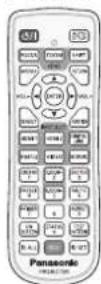
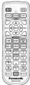
Wireless/wired remote control unit <1>
text_image
(N2QAYA000119) (N2QAYA000121)
For PT-EZ590, PT-EW650 For PT-EW550
and PT-EX620 and PT-EX520
Lens cover <1>
natural_image
Simple line drawing of a circular object with two parallel lines, no text or symbols present.
CD-ROM <1>
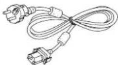
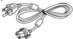
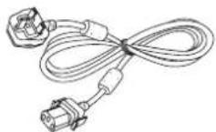
Power cord
(TXFSX01RWDZ)
(TXFSX01RXRZ)
(TXFSX02UTRZ)
AAA/R03 or AAA/LR03 battery <2>
Lens release button fixing screw <1>
Attention
• After unpacking the projector, discard the power cord cap and packaging material properly.
Note
The type and number of the supplied power cords vary depending on the country or region where you purchased the product.
The model numbers of accessories are subject to change without prior notice.
Contents of the supplied CD-ROM
The contents of the supplied CD-ROM are as follows.
Instruction/list (PDF) Operating Instructions Software Multi Monitoring & Control Software (Windows) This software allows you to monitor and control multiple displays (projector or flat panel display) connected to the LAN. Logo Transfer Software (Windows) This software allows you to transfer original images, such as company logos to be displayed when projection starts, to the projector.
Optional accessories
Optional accessories (product name) Model No. Zoom Lens ET-ELT30, ET-ELT31 ^1 , ET-ELW30 ^1 , ET-ELW31 Ceiling Mount Bracket ET-PKD120H (for High Ceilings)ET-PKD120S (for Low Ceilings)ET-PKE300B (Projector Mount Bracket) Replacement Lamp Unit ET-LAEF100 Replacement Filter Unit ET -RFE300 Early Warning Software (Basic license/3-year license) ET-SWA100 Series ^2 Digital Interface Box ET-YF B100G DIGITAL LINK Switcher ET-YFB200G Wireless Module ET-WML100E / ET-WML100U ^3
*1 Scheduled in July 2016 began to be put into the market.
*2 The suffix of the Model No. differs according to the license type.
*3 In this document, the alphabet letters at the end of the model numbers are omitted.
Note
- The model numbers of optional accessories are subject to change without prior notice.
About your projector
Remote control
Front
text_image
1
2
3
4
5
6
7
8
9
10
1
2
3
4
5
6
7
8
9
10
P/TIMER 7
ON SCREEN
ID ALL
ECON
ID SET
11
AUTO SETUP
12
SHIFT
RETURN
VOL-
ENTER
VOL+
DEFAULT
INPUT SELECT
HDMI 1
HDMI 2
DIGITAL LINK
RGB 1/2
VIDEO
NETWORK
SCREEN 1/2
DZOOM-2
SHUTTER 3
FREEZE 4
DZOOM-5
MUTE 6
ASPECT 9
STATUS 0
TEST PATTERN
13
14
15
16
Panasonic PROJECTOR
For PT-EW550 / PT-EX520
text_image
Panasonic
PROJECTOR
13
Top
natural_image
Top-down view of a car head with two wheels and a labeled component (no text or symbols beyond the number 24)
Bottom
text_image
17
SCREEN 1
FREEZE 4
P-TIMER 7
ON SCREEN
ECO
0
STATUS
8
ASPECT 9
MUTE 6
MUTTER 3
DZOOM-2
DZOOM-5
20
21
22
23
text_image
25
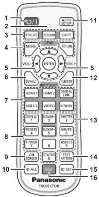
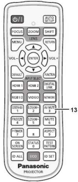
1 Power <|content_end|> button (standby/ | power on)
Sets the projector to the state where the projector is switched off (standby mode) when the switch on the projector is set to and in the projection mode.
Also starts projection when the power is switched off (standby mode).
2 Remote control indicator
Blinks if any button in the remote control is pressed.
3 Lens (, , ) buttons
Adjusts the projection lens. (→ page 52)
4
button/ button/ button/
Used to navigate through the menu screen. (→ page 62)
5 button/ button
Adjusts the volume of the built-in speaker or audio output.
(→ page 55)
6 button
Resets the content of the sub-menu to the factory default.
(→ page 63)
7 Input selection (, ", , , , ) buttons
Switches the input signal to project. (→ page 51)
(*1 This button is disabled for PT-EW550 and PT-EX520.)
8 Number (<0> \~ <9>) buttons
Used for entering an ID number or a password in a multiple projectors environment.
9 button
Switches on (display)/off (hide) the on-screen display function. (→ page 55)
10 button
Used to simultaneously control all the projectors with a single remote control in a multiple projector environment. (→ page 59)
11 button
Automatically adjusts the image display position while the image is projected. (→ page 56)
12 button
Assigns a frequently used operation as a shortcut button.
(→ page 58)
13 button/ button
( button is for PT-EZ590, PT-EW650 and PT-EX620.
button is for PT-EW550 and PT-EX520.)
Used when temporarily turning off the image and the audio.
(→ page 54)
14 button
Displays the test pattern. (→ page 58)
15 button
Sets the ID number of the remote control in a multiple projector environment. (→ page 59)
16 button
Displays the setting screen relating to ECO management. (→ pages 59, 93)
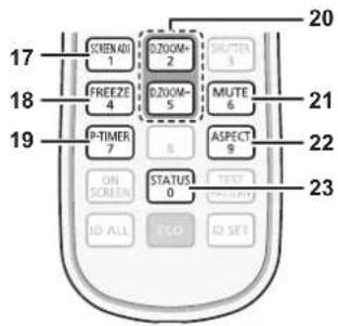
17 button
You can correct various types of distortion in a projected image. (→ page 56)
18 button
Used when pausing the image and turning off the audio.
(→ page 55)
19 button
Operates the presentation timer function. (→ page 58)
20 button/ button
Zoom in and out the images. (→ page 57)
21 button
Used when temporarily turning off the audio. (→ page 55)
22 button
Switches the aspect ratio of the image. (→ page 57)
23 button
Displays the projector information. (→ pages 59, 92)
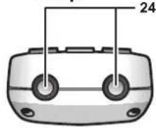
24 Remote control signal transmitter
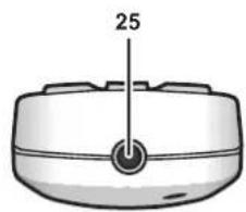
25 Remote control wired terminal
This is the terminal used to connect to the projector via a cable when the remote control is used as a wired remote control.
(→ page 29)
Attention
text_image
CAUTION
1.Do not use old battery with new one.
2.Do not use batteries other than the type specified.
3.Be sure the batteries are inserted properly.
Caution label at the back of the remote control
Note
When operating the remote control by directly pointing the remote control signal receiver of the projector, operate the remote control at a distance approx. 30 m (98'5") or shorter from the remote control signal receiver. The remote control can control at angles of up to ±30° vertically and horizontally, but the effective control range may be reduced.
If there are any obstacles between the remote control and the remote control signal receiver, the remote control may not operate properly.
The signal will be reflected off the screen. However, the operating range may be limited from light reflection loss due to the screen material.
If the remote control signal receiver directly receives strong light, such as fluorescent light, the remote control may not operate properly. Use it in a place distant from the light source.
The power indicator will blink if the projector receives a remote control signal.
Projector body
Front
text_image
12345
6
7986
Side
text_image
17
18
Rear
text_image
10
11
12131514
16
natural_image
Technical diagram of a mechanical device with labeled component 10, showing internal structure and directional arrow (no text or symbols beyond labels)
WARNING
Keep your hands and other objects away from the air exhaust port.
Keep your hands and face away.
Do not insert your fingers.
Keep heat-sensitive objects away.
Heated air from the air exhaust port can cause burns, injury, or deformations.
1 Remote control signal receiver (front)
Displays the status of the power. Displays the status of the lamp. Displays the status of the internal temperature.
5 Filter indicator
Displays the status of the air filter unit.
6 Adjustable feet
Adjusts the projection angle.
7 Speaker
8 Lens release button (→ page 38)
9 Projection lens
(Only models with lens)
10 Air exhaust port
11 Remote control signal receiver (rear)
12 terminal
Connect the supplied power cord.
13 switch
Turns off/on the main power.
14 Connecting terminals (→ page 28)
15 Security slot
This security slot is compatible with the Kensington security cables.
16 Control panel (→ page 27)
Bottom
text_image
: Projection direction
19
19 Lens release button fixing screw hole
When you replace the projection lens, you can use if you want to fix the lens release button.
18 Air intake port
text_image
Top
21
Panasonic
222018
21 Luminance sensor
Measures the brightness of the installation environment. When the daylight view function is set to [AUTO], the vividness of the image is automatically corrected. (→ page 69)
Attention
- Do not block the ventilation ports (intake and exhaust) of the projector.
■Control panel
text_image
1
2
3
4
5
MENU
INPUT SELECT
VOL-
ENTER
VOL+
SHUTTER
LENS
6
1 Power <∅/|> button (∅ standby/| power on)
Sets the projector to the state where the projector is switched off (standby mode) when the switch on the projector is set to and in the projection mode. Also starts projection when the power is switched off (standby mode). button/ button/▲▼◀▶ buttons
Used to navigate through the menu screen. (→ page 62)
Returns to the previous menu when a sub-menu is displayed.
Also used to enter a password in [SECURITY] or enter characters. button/ button
Adjusts the volume of audio output. (→ page 55)
4 button/ button
( button is for PT-EZ590, PT-EW650 and PT-EX620.
button is for PT-EW550 and PT-EX520.)
Used when temporarily turning off the image and audio.
(→ page 54) button
Adjusts the focus, zoom, and shift (position) of the lens.
■Connecting terminals
text_image
1234567
WIRELESS
G/Y
RGB 1 IN
B/Pa/C
R/Pr
SYNC/HD
VD
RGB 2 IN
MONITOR OUT
SERIAL IN
810911121314
DC OUT
5V 900mA
REMOTE 1 IN
VIDEO IN
AUDIO IN
REMOTE 2 IN
L
R
VARIABLE
AUDIO OUT
LAN
DIGITAL LINK
LAN
1 terminal
Insert the optional wireless module (Model No.: ET-WML100) directly to this terminal when using the wireless LAN function.
2 (, , , , ) terminals
This is the terminal to input RGB signals, YC_BC_R/YP_BP_R signals, or Y/C signals.
3 terminal
This is the terminal to input RGB signals or YC_BC_R/YP_BP_R signals.
4 terminal
This is the terminal to output analog RGB signals and YC_BC_R/YP_BP_R signals that were input to the terminal or the terminal to an external device. When the input is switched to RGB1 or RGB2, the corresponding signals are output.
5 terminal/ terminal
This is the terminal to input HDMI signals.
6 terminal
This is the LAN terminal to connect to the network.
7 terminal
(Only for PT-EZ590, PT-EW650 and PT-EX620)
This is the LAN terminal to connect to the network. This is also used when connecting a video signal transmission device via the LAN terminal.
8 terminal
This is a USB terminal only for power supply. (DC 5 V, maximum 900 mA)
This can be used when power is to be supplied to a wireless display adapter, etc.
9 terminal
This is a terminal to remotely control the projector using the external control circuit.
10 terminal
This is the RS-232C compatible terminal to externally control the projector by connecting a computer.
11 terminal
This is the terminal to input video signals.
12 terminal/ terminal/
terminal
This is the terminal to input audio. Left input and right input are provided for the terminal.
13 terminal
This is the terminal to output the input audio signal to the projector.
14 terminal
This is the terminal to connect to the remote control by cable when controlling the projector by wired remote control.
Attention
Preparing the remote control
Inserting and removing the batteries
text_image
i)
ii)
natural_image
Diagram of a remote control panel with labeled buttons and ports (no text or symbols)
Fig. 1 Fig. 2
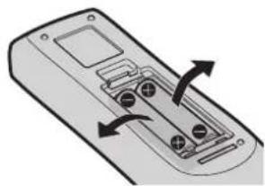
1) Open the cover. (Fig. 1)
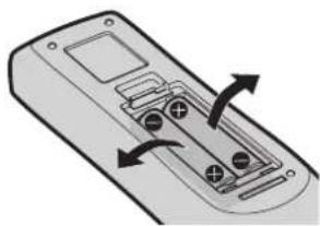
2) Insert the batteries and close the cover (insert the ⬤ side first). (Fig. 2)
- When removing the batteries, perform the steps in reverse order.
When using the system with multiple projectors
When you use the system with multiple projectors, you can operate all the projectors simultaneously or each projector individually by using single remote control, if a unique ID number is assigned to each projector.
When you want to set the ID number, at first you need to complete the Initial setting, and then after setting the ID number of the projector, set the ID number on the remote control.
About Initial setting, please refer to "When the initial setting screen is displayed" (→ page 47).
The factory default ID number of the unit (the projector and the remote control) is set to [ALL], you can control with this setting. If necessary, please set the ID number to the remote control and the projector.
About how to set the ID number of the remote control, please refer to "Setting the ID number of the remote control" (→ page 59).
Note
- Set the ID number of the projector from the [PROJECTOR SETUP] menu → [PROJECTOR ID] (→ page 92).
Connecting the remote control to the projector with a cable
When you use the system with multiple projectors, use commercially available M3 stereo mini jack cables and connect the other devices to the terminal of the projector.
The remote control is effective even in places where an obstacle stands in the light path or where devices are susceptible to outside light.
text_image
Remote control
M3 stereo mini plug cable (commercially available)
Connecting to the remote control wired terminal
Connecting terminals
Attention
- Use a cable that is 15 m (49'3") or shorter, with 2 core shielded. The remote control may not operate when the length of the cable exceeds 15 m (49'3") or when the shielding of the cable is inadequate.
Chapter 2 Getting Started
This chapter describes things you need to do before using the projector such as the setup and connections.
Setting up
Installation mode
There are four ways to set up the projector. Set the [PROJECTOR SETUP] menu → [PROJECTION METHOD] (→ page 93) depending on the installation method.
Mounting on the ceiling and projecting forward Mounting on the ceiling and projecting from rear
natural_image
Simple line drawing of a person sitting on a chair facing a projector screen, with no text or symbols present.
Menu item Method Menu item Method
(Using the translucent screen)
natural_image
Simple line drawing of a rectangular box with a small screen and a seated person silhouette (no text or symbols)
[PROJECTION METHOD] [AUTO] or [FRONT/CEILING] [PROJECTION METHOD] [REAR/CEILING]
Setting on a desk/floor and projecting forward Setting on a desk/floor and projecting from rear
natural_image
Simple line drawing of a person viewing a presentation screen with a blank board (no text or symbols)
Menu item Method Menu item Method
(Using the translucent screen)
natural_image
Simple line drawing of a person sitting in front of a transparent display case with boxes, no text or symbols present.
[PROJECTION METHOD] [AUTO] or [FRONT/DESK] [PROJECTION METHOD] [REAR/DESK]
Note
- The projector has a built-in angle sensor. When projecting in front of the screen, if set the [PROJECTOR SETUP] menu → [PROJECTION METHOD] → [AUTO], the projector's posture will be detected automatically. When projecting from rear, please set the [PROJECTION METHOD] to [REAR/DESK] or [REAR/CEILING].
■Angle sensor
The range of installation posture detected by the projector's built-in angle sensor is as follows.
text_image
[FRONT/DESK]
30°
30°
[FRONT/CEILING]
[FRONT/DESK]
Projection direction
Parts for ceiling mount (optional)
The projector can be installed on the ceiling by combining the optional Ceiling Mount Bracket (Model No.: ET-PKD120H (for High Ceilings), ET-PKD120S (for Low Ceilings)) and ET-PKE300B (Projector Mount Bracket).
Be sure to use the Ceiling Mount Bracket specified for this projector.
Refer to the Installation Instructions supplied with the Ceiling Mount Bracket when installing the projector with the bracket.
Attention
- To ensure projector performance and security, installation of the Ceiling Mount Bracket must be carried out by your dealer or a qualified technician.
Projected image and throw distance
Refer to the screen size and projection distances to install the projector. Image size and image position can be adjusted in accordance with the screen size and screen position.
Note
- This illustration is represented on the assumption that the size and position of the projection screen are matched to fill the screen.
(Unit: m)
L (LW/LT)1 Projection distance L1 Lens protrusion dimension SH Projected image height SW Projected image width H Distance from the lens center to the bottom edge of the projected image(When setting on a desk/floor, if the bottom edge of the projected image is below the lens center, the value of H is positive.) SD Projected image size
*1 LW: Minimum projection distance when the Zoom Lens is used LT: Maximum projection distance when the Zoom Lens is used
(Unit: m)
Projection lens Model No. Dimension for L1 (approximate value) Standard zoom lens 0.040 ET-ELT30 0.081 ET-ELT31 0.092 ET-ELW30 0.071 ET-ELW31 0.070
Attention
- Before setting up, read "Precautions for use" (→ page 17).
[SCREEN ADJUSTMENT] projection range
[VERTICAL KEYSTONE] (viewed from the side) [HORIZONTAL KEYSTONE] (viewed from above)
text_image
α
Screen
text_image
β
Screen
32 - ENGLISH
Vertical arc correction (viewed from the side) Horizontal arc correction (viewed from above)
text_image
L2
L2 : Projection distance
R2 : Arc radius
Screen
R2
text_image
L2
L2 : Projection distance
R2: Arc radius
Screen
R2
text_image
Arc center
Screen
R3
L3
L3 : Projection distance
R3 : Arc radius
text_image
Arc center
Screen
R3
L3
L3 : Projection distance
R3 : Arc radius
■For standard zoom lens
Model No. Only [KEYSTONE] used [KEYSTONE] and [CURVED CORRECTION] used together Only [CURVED CORRECTION] used Vertical keystone correction angle α (°) Horizontal keystone correction angle β (°) Vertical keystone correction angle α (°) Horizontal keystone correction angle β (°) Min. value of R2/L2 Min. value of R3/L3 Min. value of R2/L2 Min. value of R3/L3 PT-EZ590 ±2 ±30 ±20 ±15 1.4 2.9 0.7 1.6 PT-EW650, PT-EW550 ±35 ±35 ±35 ±35 1.0 1.0 1.0 1.0 PT-EX620, PT-EX520 ±35 ±35 ±35 ±35 0.8 0.9 0.8 0.9
Note
- When [SCREEN ADJUSTMENT] is used, the focus of the entire screen may be lost as correction increases.
- Make the curved screen a circular arc shape with one part of a perfect circle removed.
Projection distance per projection lens
A ± 5% error in listed projection distances may occur.
In addition, when [SCREEN ADJUSTMENT] is used, distance is corrected to become smaller than the specified screen size.
For PT-EZ590, PT-EW650, PT-EW550
■When the image aspect ratio is 16:10
Lens type Standard zoom lens Optional lens Height position (H) Short focus zoom lens Short focus zoom lens Long focus zoom lens Ultra long focus zoom lens Projection Lens Model No. — ET-ELW31 ET-ELW30 ET-ELT30 ET-ELT31 Standard zoom lens / ET-ELW31 / ET-ELW30 / ET-ELT30 / ET-ELT31 Throw ratio*1 1.22-2.26:1 0,74-0.96:1 0.96-1.22:1 2.23 - 4.02:1 4.02-7.20:1 Projected image size Projection distance (L) Diagonal (SD) Height (SH) Width (SW) Min. (LW) Max. (LT) Min. (LW) Max. (LT) Min. (LW) Max. (LT) Min. (LW) Max. (LT) Min. (LW) Max. (LT) 1.02 (40") 0.538 0.862 1.03 1.94 0.62 0.81 0.78 1.03 1.86 3.42 3.53 6.35 -0.05 ~ 0.59
Chapter 2 Getting Started — Setting up
Lens type Standard zoom lens Optional lens Height position (H) Short focus zoom lens Short focus zoom lens Long focus zoom lens Ultra long focus zoom lens Projection Lens Model No. — ET-ELW31 ET-ELW30 ET-ELT30 ET-ELT31 Standard zoom lens / ET-ELW31 / ET-ELW30 / ET-ELT30 / ET-ELT31 Throw ratio*1 1.22-2.26:1 0.74-0.96:1 0.96-1.22:1 2.23 - 4.02:1 4.02-7.20:1 Projected image size Projection distance (L) Diagonal (SD) Height (SH) Width (SW) Min. (LW) Max. (LT) Min. (LW) Max. (LT) Min. (LW) Max. (LT) Min. (LW) Max. (LT) Min. (LW) Max. (LT) Min. (LW) Max. (LT) 1.27 (50") 0.67 3 1.077 1.29 2.42 0.78 1.02 0.98 1.29 2.35 4.29 9 4.37 7.88 -0.07 ~ 0.74 1.52 (60") 0.80 8 1.292 1.55 2.91 0.94 1.23 1.18 1.55 2.83 5.16 5.21 9.41 -0.08 ~ 0.89 1.78 (70") 0.94 2 1.506 1.82 3.41 1.10 1.44 1.39 1.82 3.33 6.06 6.08 11.00 -0.09 ~ 1.04 2.03 (80") 1.07 7 1.723 2.09 3.89 1.26 1.65 1.59 2.08 3.82 6.93 6.93 12.54 -0.11 ~ 1.18 2.29 (90") 1.21 2 1.939 2.36 4.40 1.43 1.87 1.79 2.35 4.32 7.84 7.80 14.13 -0.12 ~ 1.34 2.54 (100") 1.34 46 2.154 2.62 4.88 1.59 2.07 1.99 2.61 4.80 8.71 8.64 15.66 -0.13 ~ 1.48 3.05 (120") 1.615 2.585 3.15 5.87 1.91 2.50 2.40 3.14 5.79 10.49 10.35 18.79 -0.16 ~ 1.78 3.81 (150") 2.019 3.231 3.94 7.34 2.40 3.13 3.01 3.93 7.26 13.13 12.91 23.44 -0.20 ~ 2.22 5.08 (200") 2.692 4.308 5.27 9.79 3.21 4.18 4.02 5.25 9.71 17.55 17.18 31.23 -0.27 ~ 2.96 6.35 (250") 3.365 5.385 6.59 12.25 4.01 5.23 5.03 6.57 12.17 21.98 21.45 39.01 -0.34 ~ 3.70 7.62 (300") 4.039 6.462 7.92 14.71 4.82 6.29 6.05 7.89 14.63 26.40 25.72 46.79 -0.40 ~ 4.44 8.89 (350") 4.712 7.539 9.24 17.16 5.63 7.34 7.06 9.21 17.08 30.82 29.99 54.58 -0.47 ~ 5.18 10.16 (400") 5.385 8.616 10.57 19.62 6.44 8.39 8.07 10.53 19.54 35.25 34.26 62.36 -0.54 ~ 5.92
*1 The throw ratio is based on the value during projection with the projected image size of 2.03 m (80").
■ When the image aspect ratio is 16:9
Lens type Standard zoom lens Optional lens Height position (H) Short focus zoom lens Short focus zoom lens Long focus zoom lens Ultra long focus zoom lens Projection Lens Model No. — ET-ELW31 ET-ELW30 ET-ELT30 ET-ELT31 Standard zoom lens / ET-ELW31 / ET-ELW30 / ET-ELT30 / ET-ELT31 Throw ratio*1 1.22-2.26:1 0.74-0.96:1 0.96-1.22:1 2.23-4.02:1 4.02-7.20:1 Projected image size Projection distance (L) Diagonal (SD) Height (SH) Width (SW) Min. (LW) Max. (LT) Min. (LW) Max. (LT) Min. (LW) Max. (LT) Min. (LW) Max. (LT) Min. (LW) Max. (LT) 1.02 (40") 0.498 0.886 1.06 1.99 0.64 0.84 0.80 1.06 1.92 3.51 3.62 6.52 -0.08 ~ 0.58 1.27 (50") 0.622 1.107 1.33 2.49 0.80 1.05 1.01 1.32 2.41 4.41 4.49 8.09 -0.10 ~ 0.73 1.52 (60") 0.745 1.325 1.60 2.99 0.96 1.26 1.21 1.59 2.91 5.30 5.35 9.67 -0.12 ~ 0.87 1.78 (70") 0.872 1.552 1.88 3.51 1.13 1.48 1.43 1.87 3.43 6.23 6.25 11.31 -0.15 ~ 1.02 2.03 (80") 0.995 1.770 2.14 4.00 1.30 1.70 1.63 2.13 3.92 7.13 7.12 12.88 -0.17 ~ 1.16 2.29 (90") 1.122 1.997 2.42 4.52 1.47 1.92 1.84 2.41 4.44 8.06 8.01 14.52 -0.19 ~ 1.31 2.54 (100") 1.245 2.215 2.69 5.02 1.63 2.13 2.05 2.68 4.94 8.96 8.88 16.09 -0.21 ~ 1.45 3.05 (120") 1.495 2.660 3.24 6.03 1.97 2.57 2.47 3.22 5.95 10.78 10.64 19.31 -0.25 ~ 1.74 3.81 (150") 1.867 3.322 4.05 7.54 2.46 3.21 3.09 4.04 7.46 13.50 13.27 24.09 -0.31 ~ 2.18 5.08 (200") 2.489 4.430 5.42 10.07 3.30 4.30 4.13 5.39 9.99 18.05 17.66 32.09 -0.41 ~ 2.90 6.35 (250") 3.112 5.537 6.78 12.59 4.13 5.38 5.17 6.75 12.51 22.59 22.04 40.09 -0.52 ~ 3.63 7.62 (300") 3.734 6.645 8.14 15.11 4.96 6.46 6.22 8.11 15.04 27.14 26.43 48.09 -0.62 ~ 4.36 8.89 (350") 4.356 7.752 9.50 17.64 5.79 7.55 7.26 9.46 17.56 31.68 30.82 56.09 -0.73 ~ 5.08 10.16 (400") 4.978 8.860 10.86 20.16 6.62 8.63 8.30 10.82 20.09 36.23 35.21 64.09 -0.83 ~ 5.81
*1 The throw ratio is based on the value during projection with the projected image size of 2.03 m (80").
■ When the image aspect ratio is 4:3
Lens type Standard zoom lens Optional lens Height position (H) Short focus zoom lens Short focus zoom lens Long focus zoom lens Ultra long focus zoom lens Projection Lens Model No. — ET-ELW31 ET-ELW30 ET-ELT30 ET-ELT31 Standard zoom lens / ET-ELW31 / ET-ELW30 / ET-ELT30 / ET-ELT31 Throw ratio ^1 1.46-2.72:1 0.88-1.15:1 1.11-1.45:1 2.67-4.84:1 4.82-8.73:1 Projected image size Projection distance (L) Diagonal (SD) Height (SH) Width (SW) Min. (LW) Max. (LT) Min. (LW) Max. (LT) Min. (LW) Max. (LT) Min. (LW) Max. (LT) Min. (LW) Max. (LT) 1.02 (40") 0.610 0.813 1.17 2.20 0.70 0.92 0.89 1.17 2.12 3.88 3.98 7.17 -0.06 ~ 0.67 1.27 (50") 0.762 1.016 1.47 2.75 0.88 1.16 1.11 1.46 2.67 4.87 4.93 8.91 -0.08 ~ 0.84 1.52 (60") 0.912 1.216 1.76 3.30 1.06 1.39 1.34 1.75 3.22 5.86 5.89 10.64 -0.09 ~ 1.00 1.78 (70") 1.068 1.424 2.07 3.86 1.25 1.64 1.57 2.06 3.79 6.88 6.88 12.44 -0.11 ~ 1.18 2.03 (80") 1.218 1.624 2.37 4.41 1.43 1.87 1.80 2.35 4.33 7.87 7.83 14.18 -0.12 ~ 1.34 2.29 (90") 1.374 1.832 2.67 4.98 1.62 2.12 2.04 2.66 4.90 8.89 8.82 15.98 -0.14 ~ 1.51
Lens type Standard zoom lens Optional lens Height position (H) Short focus zoom lens Short focus zoom lens Long focus zoom lens Ultra long focus zoom lens Projection Lens Model No. — ET-ELW31 ET-ELW30 ET-ELT30 ET-ELT31 Standard zoom lens / ET-ELW31 / ET-ELW30 / ET-ELT30 / ET-ELT31 Throw ratio ^1 1.46-2.72:1 0 88-1.15:1 1.11-1.45:1 2.67-4.84:1 4.82-8.73: 1 Projected image size Projection distance (L) Diagonal (SD) Height (SH) Width (SW) Min. (LW) Max. (LT) Min. (LW) Max. (LT) Min. (LW) Max. (LT) Min. (LW) Max. (LT) Min. (LW) Max. (LT) Min. (LW) Max. (LT) 2.54 (100") 1.5 24 2.032 2.97 5 5.53 1.80 2.35 2.26 2.95 5.45 9.88 9 77 17.7 2 -0.15 ~ 1.68 3.05 (120") 1.8 30 2.440 3.57 6 6.65 2.17 2.83 2.72 3.56 6.57 11.89 11.71 21 26 -0.18 ~ 2.01 3.81 (150") 2.2 36 3.048 4.47 8 3.31 2.72 3.54 3.41 4.45 8.23 14.88 14.60 26 53 -0.23 ~ 2.52 5.08 (200") 3.0 48 4.064 5.97 1 1.09 3.63 4.74 4.56 5 94 11.01 19.89 19.44 35.34 -0.31 ~ 3.35 6.35 (250") 3.8 10 5.080 7.47 1 3.87 4.55 5.93 5.70 7 44 13.79 24.90 24.27 44.15 -0.38 ~ 4.19 7.62 (300") 4.572 6.096 8.97 16.65 5.47 7.12 6.85 8.93 16.57 29.90 29.10 52.96 -0.46 ~ 5.03 8.89 (350") 5.334 7.112 10.47 19.43 6.38 8.31 8.00 10.43 19.35 34.91 33.94 61.77 -0.53 ~ 5.87 10.16 (400") 6.096 8.128 11.97 22.21 7.30 9.51 9.14 11.92 22.14 39.92 38.77 70.59 -0.61 ~ 6.71
*1 The throw ratio is based on the value during projection with the projected image size of 2.03 m (80").
For PT-EX620 and PT-EX520
■ When the image aspect ratio is 4:3
(Unit: m)
Lens type Standard zoom lens Optional lens Height position (H) Short focus zoom lens Short focus zoom lens Long focus zoom lens Ultra long focus zoom lens Projection Lens Model No. — ET-ELW31 ET-ELW30 ET-ELT30 ET-ELT31 Standard zoom lens / ET-ELW31 / ET-ELW30 / ET-ELT30 / ET-ELT31 Throw ratio*1 1.32-2.44:1 0.79-1.08:1 1.00-1.30:1 2.39-4.36:1 4.34-7.86:1 Projected image size Projection distance (L) Diagonal (SD) Height (SH) Width (SW) Min. (LW) Max. (LT) Min. (LW) Max. (LT) Min. (LW) Max. (LT) Min. (LW) Max. (LT) Min. (LW) Max. (LT) 1.02 (40") 0.610 0.813 1.05 1.98 0.63 0.90 0.80 1.05 1.90 3.51 3.60 6.46 0.00 ~ 0.61 1.27 (50") 0.762 1.016 1.32 2.47 0.79 1.11 1.00 1.31 2.39 4.39 4.45 8.03 0.00 ~ 0.76 1.52 (60") 0.912 1.216 1.58 2.96 0.95 1.32 1.20 1.58 2.88 5.28 5.31 9.59 0.00 ~ 0.91 1.78 (70") 1.068 1.424 1.86 3.47 1.12 1.54 1.41 1.85 3.39 6.20 6.20 11.21 0.00 ~ 1.07 2.03 (80") 1.218 1.624 2.12 3.97 1.29 1.75 1.62 2.12 3.89 7.09 7.06 12.77 0.00 ~ 1.22 2.29 (90") 1.374 1.832 2.40 4.48 1.45 1.97 1.83 2.39 4.40 8.01 7.95 14.40 0.00 ~ 1.37 2.54 (100") 1.524 2.032 2.67 4.97 1.62 2.18 2.03 2.66 4.89 8.89 8.80 15.96 0.00 ~ 1.52 3.05 (120") 1.830 2.440 3.21 5.98 1.95 2.61 2.45 3.20 5.90 10.70 10.55 19.14 0.00 ~ 1.83 3.81 (150") 2.286 3.048 4.02 7.47 2.44 3.26 3.06 4.00 7.39 13.40 13.16 23.89 0.00 ~ 2.29 5.08 (200") 3.048 4.064 5.37 9.98 3.27 4.33 4.10 5.35 9.90 17.90 17.51 31.82 0.00 ~ 3.05 6.35 (250") 3.810 5.080 6.72 12.48 4.09 5.40 5.13 6.69 12.40 22.40 21.86 39.75 0.00 ~ 3.81 7.62 (300") 4.572 6.096 8.07 14.98 4.91 6.48 6.16 8.04 14.90 26.91 26.21 47.68 0.00 ~ 4.57 8.89 (350") 5.334 7.112 9.42 17.49 5.74 7.55 7.19 9.38 17.41 31.41 30.56 55.61 0.00 ~ 5.33 10.16 (400") 6.096 8.128 10.77 19.99 6.56 8.62 8.22 10.73 19.91 35.91 34.91 63.55 0.00 ~ 6.10
*1 The throw ratio is based on the value during projection with the projected image size of 2.03 m (80").
■ When the image aspect ratio is 16:9
(Unit: m)
Lens type Standard zoom lens Optional lens Height position (H) Short focus zoom lens Short focus zoom lens Long focus zoom lens Ultra long focus zoom lens Projection Lens Model No. — ET-ELW31 ET-ELW30 ET-ELT30 ET-ELT31 Standard zoom lens / ET-ELW31 / ET-ELW30 / ET-ELT30 / ET-ELT31 Throw ratio ^1 1.32-2.44:1 0 79-1.08:1 1.00-1.30:1 2.40-4.37:1 4.34-7.86:1 Projected image size Projection distance (L) Diagonal (SD) Height (SH) Width (SW) Min. (LW) Max. (LT) Min. (LW) Max. (LT) Min. (LW) Max. (LT) Min. (LW) Max. (LT) Min. (LW) Max. (LT) 1.02 (40") 0.498 0.886 1.15 2.16 0.69 0.97 0.87 1.14 2.08 3.83 3.91 7.03 -0.08 ~ 0.58 1.27 (50") 0.622 1.107 1.44 2.69 0.87 1.20 1.09 1.43 2.61 4.79 4.84 8.74 -0.10 ~ 0.73 1.52 (60") 0.745 1.325 1.73 3.23 1.04 1.43 1.31 1.72 3.15 5.76 5.77 10.44 -0.12 ~ 0.87 1.78 (70") 0.872 1.552 2.03 3.79 1.23 1.67 1.54 2.02 3.71 6.76 6.75 12.21 -0.15 ~ 1.02 2.03 (80") 0.995 1.770 2.32 4.32 1.40 1.90 1.76 2.31 4.25 7.73 7.68 13.91 -0.17 ~ 1.16 2.29 (90") 1.122 1.997 2.62 4.88 1.59 2.14 1.99 2.61 4.80 8.73 8.65 15.68 -0.19 ~ 1.31 2.54 (100") 1.2 45 2.215 2.91 5 42 1.76 2.37 2.22 2.90 5.34 9.70 9 58 17.38 -0.21 ~ 1.45 3.05 (120") 1.4 95 2.660 3.50 6 51 2.12 2.84 2.67 3.48 6.44 11.67 11.49 20.85 -0.25 ~ 1.74
Chapter 2 Getting Started — Setting up
Lens type Standard zoom lens Optional lens Height position (H) Short focus zoom lens Short focus zoom lens Long focus zoom lens Ultra long focus zoom lens Projection Lens Model No. — ET-ELW31 ET-ELW30 ET-ELT30 ET-ELT31 Standard zoom lens / ET-ELW31 / ET-ELW30 / ET-ELT30 / ET-ELT31 Throw ratio*1 1.32-2.44:1 0 79-1.08:1 1.00-1 1.30:1 2.40-4.37:1 Projected image size Projection distance (L) Diagonal (SD) Height (SH) Width (SW) Min. (LW) Max. (LT) Min. (LW) Max. (LT) Min. (LW) Max. (LT) Min. (LW) Max. (LT) Min. (LW) Max. (LT) Min. (LW) Max. (LT) 3.81 (150") 1.867 3.322 4.38 8.15 2.66 3.54 3.34 4.36 8.07 14.61 14.32 26.02 5.08 (200") 2.489 4.430 5.85 10.87 3.56 4.71 4.47 5 83 10.79 19.51 19.06 34.66 6.35 (250") 3.112 5.537 7.32 13.60 4.46 5.88 5.59 7 29 13.52 24.42 23.81 43.30 7.62 (300") 4.572 6.096 8.79 16.33 5.36 7.05 6.71 8 76 16.25 29.32 28.55 51.94 8.89 (350") 5.334 7.112 10.26 19.05 6.26 8.22 7.84 10.22 18.97 34.23 33.29 60.58 -0.73 ~ 5.08 10.16 (400") 6.096 8.128 11.73 21.78 7.15 9.39 8.96 11.69 21.70 39.13 38.03 69.22 -0.83 ~ 5.81
*1 The throw ratio is based on the value during projection with the projected image size of 2.03 m (80").
To use a screen size not listed in this manual, check the screen size SD (m) and use the respective formula to calculate projection distance.
The unit of all the formulae is m. (Values obtained by the following calculation formulae contain a slight error.) When calculating a projection distance using image size designation (value in inches), multiply the value in inches by 0.0254 and substitute it into SD in the formula for calculating the projection distance.
For PT-EZ590, PT-EW650, PT-EW550
Lens type Projection Lens Model No. Aspect ratio Projection distance (L) formula Standard zoom lens — 16:10 Min. (LW) L = 1.0433 × SD - 0.0326 Max. (LT) L = 1.9341 × SD - 0.0328 16:9 Min. (LW) L = 1.0724 × SD - 0.0326 Max. (LT) L = 1.9878 × SD - 0.0328 4:3 Min. (LW) L = 1.1811 × SD - 0.0326 Max. (LT) L = 2.1895 × SD - 0.0328 Short focus zoom lens ET-ELW31 16:10 Min. (LW) L = 0.6373 × SD - 0.0324 Max. (LT) L = 0.8295 × SD - 0.0344 16:9 Min. (LW) L = 0.6550 × SD - 0.0324 Max. (LT) L = 0.8526 × SD - 0.0344 4:3 Min. (LW) L = 0.7215 × SD - 0.0324 Max. (LT) L = 0.9391 × SD - 0.0344 Short focus zoom lens ET-ELW30 16:10 Min. (LW) L = 0.7978 × SD - 0.0326 Max. (LT) L = 1.0395 × SD - 0.0341 16:9 Min. (LW) L = 0.8199 × SD - 0.0326 Max. (LT) L = 1.0684 × SD - 0.0341 4:3 Min. (LW) L = 0.9031 × SD - 0.0326 Max. (LT) L = 1.1768 × SD - 0.0341 Long focus zoom lens ET-ELT30 16:10 Min. (LW) L = 1.9341 × SD - 0.1109 Max. (LT) L = 3.4825 × SD - 0.1364 16:9 Min. (LW) L = 1.9879 × SD - 0.1109 Max. (LT) L = 3.5793 × SD - 0.1364 4:3 Min. (LW) L = 2.1896 × SD - 0.1109 Max. (LT) L = 3.9424 × SD - 0.1364
Chapter 2 Getting Started — Setting up
Lens type Projection Lens Model No. Aspect ratio P Projection distance (L) formula Ultra long focus zoom lens ET ELT31 16:10 Min. (LW) L = 3.3622 x SD + 0.1001 Max. (LT) L = 6.1287 x SD + 0.0940 16:9 Min. (LW) L = 3.4557 x SD + 0.1001 Max. (LT) L = 6.2991 x SD + 0.0940 4:3 Min. (LW) L = 3.8063 x SD + 0.1001 Max. (LT) L = 6.9382 x SD + 0.0940
For PT-EX620 and PT-EX520
Lens type Projection Lens Model No. Aspect ratio P Projection distance (L) formula Standard zoom lens — 4:3 Min. (LW) L = 1.0630 x SD - 0.0332 Max. (LT) L = 1.9706 x SD - 0.0334 16:9 Min. (LW) L = 1.1581 x SD - 0.0332 Max. (LT) L = 2.1469 x SD - 0.0334 Short focus zoom lens ET-ELW31 ELW31 4:3 Min. (LW) L = 0.6493 x SD - 0.0330 Max. (LT) L = 0.8452 x SD + 0.0350 16:9 Min. (LW) L = 0.7074 x SD - 0.0330 Max. (LT) L = 0.9208 x SD + 0.0350 Short focus zoom lens ET-ELW30 ELW30 4:3 Min. (LW) L = 0.8128 x SD - 0.0333 Max. (LT) L = 1.0591 x SD - 0.0347 16:9 Min. (LW) L = 0.8855 x SD - 0.0333 Max. (LT) L = 1.1539 x SD - 0.0347 Long focus zoom lens ET-ELT30 ELT30 4:3 Min. (LW) L = 1.9706 x SD - 0.1130 Max. (LT) L = 3.5456 x SD - 0.1114 16:9 Min. (LW) L = 2.1469 x SD - 0.1130 Max. (LT) L = 3.8628 x SD - 0.1114 Ultra long focus zoom lens ET-ELT31 ELT31 4:3 Min. (LW) L = 3.4264 x SD + 0.1005 Max. (LT) L = 6.2453 x SD + 0.0941 16:9 Min. (LW) L = 3.7330 x SD + 0.1005 Max. (LT) L = 6.8041 x SD + 0.0941
Adjusting adjustable feet
Install the projector on a flat surface so that the front of the projector is parallel to the screen surface and the projected image is rectangular.
If the screen is tilted downward, the projected image can be adjusted to be rectangular by adjusting the front adjustable feet. The adjustable feet can also be used to adjust the projector to be level when it is tilted in the horizontal direction.
Extend the adjustable feet by rotating in the direction shown in the figure and retract by rotating in the opposite direction.
natural_image
Illustration of a projector with circular lens and two curved arrows indicating rotation (no text or symbols)
Maximum adjustable range
Adjustable feet: 23 mm (29/32") each
Attention
- Heated air is expelled from the air exhaust port while the lamp is lit. Do not touch the air exhaust port directly when adjusting the adjustable feet. (→ page 26)
Removing/attaching the projection lens
Removing and attaching procedures of the projection lens are same for both standard zoom lens and optional lens.
Move the projection lens to the home position before replacing or removing the projection lens. (→ page 53)
Attention
Replace the projection lens after turning off the projector.
Do not touch the electrical contact of the projection lens. Dust or dirt may cause defective contact.
Do not touch the surface of the projection lens with your bare hands.
Before attaching the projection lens, remove the lens pad (only lens options models) and the lens cover attached to the projection lens.
Removing the projection lens
Remove the projection lens with the following procedure.
text_image
i) Lens release button
i)
ii)
iii)
Projection lens
1) With the lens release button held down, turn the projection lens counterclockwise to the end and remove the projection lens.
Attention
Store the removed projection lens where it will be free from vibration and impact.
If you cannot release the lock with lens release button held down, it indicates that the lens release button fixing screw is installed. Please remove the lens release button fixing screw. For details, refer to "When attaching the lens release button fixing screw". (→ page 39)
Attaching the projection lens
Attach the projection lens with the following procedure.
text_image
Guide groove
Red marks
Guide groove
Projection lens guide
Projection lens guide
Fig.1
Projection lens
Projection lens
Fig.2
1) Align the red mark on the projection lens with the red mark on the projector, and insert the projection lens to the end. (Fig. 1)
Attention
- Turn the projection lens counterclockwise to confirm that it does not come out.
Attach the lens antitheft screw with the following procedures.
text_image
Lens release button fixing screw
Lens release button fixing screw hole
1) Place the projector upside down on a soft cloth.
Connecting
Before connecting
Before connecting, carefully read the operating instructions for the external device to be connected.
Turn off the power of all devices before connecting cables.
Take note of the following points before connecting the cables. Failure to do so may result in malfunctions.
- When connecting a cable to a device connected to the projector or the projector itself, touch any nearby metallic objects to eliminate static electricity from your body before performing work.
Do not use unnecessarily long cables to connect a device to the projector or to the projector body. The longer the cable, the more susceptible to noise it becomes. Since using a cable while it is wound makes it act like an antenna, it is more susceptible to noise.
When connecting cables, connect GND first, then insert the connecting terminal of the connecting device in a straight manner.
- Acquire any connection cable necessary to connect the external device to the system that is neither supplied with the device nor available as an option.
- If video signals from video equipment contain too much jitter, the images on the screen may wobble. In this case, a time base corrector (TBC) must be connected.
- The projector accepts video signals, Y/C signals, YC_BC_R/YP_BP_R signals, analog RGB signals (synchronization signals are TTL level), and digital signals.
- Some computer models or graphics cards are not compatible with the projector.
- Use a cable compensator when you connect devices to the projector using long cables. Otherwise the image may not display properly.
- Refer to “List of compatible signals” ( page 156) for the types of video signals that can be used with the projector.
terminal pin assignments and signal names
Outside view Pin No. Signal name Pin No. Signal name (1) R/P R (9) +5 V (2) G/Y (10) GND (3) B/P B (11) GND (4) — (12) DDC data (5) GND (13) HD/SYNC (6) GND (14) VD (7) GND (15) DDC clock (8) GND
terminal pin assignments and signal names
Outside view Pin No. Signal name Pin No. Signal name (1) R/P _R (9) — (2) G/Y (10) GND (3) B/P _B (11) GND (4) — (12) — (5) GND (13) HD/SYNC (6) GND (14) VD (7) GND (15) — (8) GND
terminal/ terminal pin assignments and signal names
Outside view Pin No. Signal name Pin No. Signal name Even-numbered pins of (2) to (18) (1) T.M.D.S data 2+ (11) T.M.D.S clock shield (2) T.M.D.S data 2 shield (12) T.M.D.S clock - (3) T.M.D.S data 2 - (13) CEC (4) T.M.D.S data 1+ (14) — (5) T.M.D.S data 1 shield (15) SCL (6) T.M.D.S data 1 - (16) SDA (7) T.M.D.S data 0+ (17) DDC/CECGND (8) T.M.D.S data 0 shield (18) +5 V (9) T.M.D.S data 0 - (19) Hot plug detection (10) T.M.D.S clock+
Connecting example: AV equipment
flowchart
graph TD
    A["Video deck (TBC built-in)"] --> B["Video deck (TBC built-in)"]
    B --> C["Video deck"]
    D["Blu-ray disc player"] --> E["Audio equipment"]
    E --> F["Audio equipment"]
    G["Video deck (TBC built-in)"] --> H["Video deck"]
    H --> I["Video deck"]
    J["Audio equipment"] --> K["Audio equipment"]
    L["Video deck (TBC built-in)"] --> M["Video deck"]
    M --> N["Video deck"]
    O["Audio equipment"] --> P["Audio equipment"]
    Q["Video deck (TBC built-in)"] --> R["Video deck"]
    S["Audio equipment"] --> T["Audio equipment"]
Attention
• Always use one of the following when connecting a VCR.
- A VCR with built-in time base corrector (TBC)
- A time base corrector (TBC) between the projector and the VCR
- If nonstandard burst signals are connected, the image may be distorted. In such case, connect the time base corrector (TBC) between the projector and the external devices.
Note
For an HDMI cable, use an HDMI High Speed cable that conforms to HDMI standards. If a cable that does not conform to HDMI standards is used, images may be interrupted or may not be displayed.
The terminal/ terminal of the projector can be connected to an external device with a DVI-D terminal by using an HDMI/DVI conversion cable, but some devices may not project the image properly or function properly.
The projector does not support VIERA Link (HDMI).
If the [AUDIO IN SELECT] settings are incorrect, the projector may have malfunctions such as the absence of audio.
When Y/C signals are input to the terminal, switch the setting by using the [DISPLAY OPTION] menu → [RGB IN] → [RGB1 INPUT SETTING]. (→ page 82)
Connecting example: Computers
flowchart
graph TD
    A["Computer"] --> B["Optional wireless module (Model No.: ET-WML100)"]
    B --> C["Control computer"]
    C --> D["Audio equipment"]
    D --> E["Variable Audio Out"]
    E --> F["VIDEO"]
    F --> G["MONI"]
    G --> H["MONI 2 IN"]
    H --> I["MONI 1 IN"]
    I --> J["MONI 3 IN"]
    J --> K["MONI 4 IN"]
    K --> L["MONI 5 IN"]
    L --> M["MONI 6 IN"]
    M --> N["MONI 7 IN"]
    N --> O["MONI 8 IN"]
    O --> P["MONI 9 IN"]
    P --> Q["MONI 10 IN"]
    Q --> R["MONI 11 IN"]
    R --> S["MONI 12 IN"]
    S --> T["MONI 13 IN"]
    T --> U["MONI 14 IN"]
    U --> V["MONI 15 IN"]
    V --> W["MONI 16 IN"]
    W --> X["MONI 17 IN"]
    X --> Y["MONI 18 IN"]
    Y --> Z["MONI 19 IN"]
    Z --> AA["MONI 20 IN"]
    AA --> AB["MONI 21 IN"]
    AB --> AC["MONI 22 IN"]
    AC --> AD["MONI 23 IN"]
    AD --> AE["MONI 24 IN"]
    AE --> AF["MONI 25 IN"]
    AF --> AG["MONI 26 IN"]
    AG --> AH["MONI 27 IN"]
    AH --> AI["MONI 28 IN"]
    AI --> AJ["MONI 29 IN"]
    AJ --> AK["MONI 30 IN"]
    AK --> AL["MONI 31 IN"]
    AL --> AM["MONI 32 IN"]
    AM --> AN["MONI 33 IN"]
    AN --> AO["MONI 34 IN"]
    AO --> AP["MONI 35 IN"]
    AP --> AQ["MONI 36 IN"]
    AQ --> AR["MONI 37 IN"]
    AR --> AS["MONI 38 IN"]
    AS --> AT["MONI 39 IN"]
    AT --> AU["MONI 40 IN"]
    AU --> AV["MONI 41 IN"]
    AV --> AW["MONI 42 IN"]
    AW --> AX["MONI 43 IN"]
    AX --> AY["MONI 44 IN"]
    AY --> AZ["MONI 45 IN"]
    AZ --> BA["MONI 46 IN"]
    BA --> BB["MONI 47 IN"]
    BB --> BC["MONI 48 IN"]
    BC --> BD["MONI 49 IN"]
    BD --> BE["MONI 50 IN"]
    BE --> BF["MONI 51 IN"]
    BF --> BG["MONI 52 IN"]
    BG --> BH["MONI 53 IN"]
    BH --> BI["MONI 54 IN"]
    BI --> BJ["MONI 55 IN"]
    BJ --> BK["MONI 56 IN"]
    BK --> BL["MONI 57 IN"]
    BL --> BM["MONI 58 IN"]
    BM --> BN["MONI 59 IN"]
    BN --> BO["MONI 60 IN"]
    BO --> BP["MONI 61 IN"]
    BP --> BQ["MONI 62 IN"]
    BQ --> BR["MONI 63 IN"]
    BR --> BS["MONI 64 IN"]
    BS --> BT["MONI 65 IN"]
    BT --> BU["MONI 66 IN"]
    BU --> BV["MONI 67 IN"]
    BV --> BW["MONI 68 IN"]
    BW --> BX["MONI 69 IN"]
    BX --> BY["MONI 70 IN"]
    BY --> BZ["MONI 71 IN"]
    BZ --> CA["MONI 72 IN"]
    CA --> CB["MONI 73 IN"]
    CB --> CC["MONI 74 IN"]
    CC --> CD["MONI 75 IN"]
    CD --> CE["MONI 76 IN"]
    CE --> CF["MONI 77 IN"]
    CF --> CG["MONI 78 IN"]
    CG --> CH["MONI 79 IN"]
    CH --> CI["MONI 80 IN"]
    CI --> CJ["MONI 81 IN"]
    CJ --> CK["MONI 82 IN"]
    CK --> CL["MONI 83 IN"]
    CL --> CM["MONI 84 IN"]
    CM --> CN["MONI 85 IN"]
    CN --> CO["MONI 86 IN"]
    CO --> CP["MONI 87 IN"]
    CP --> CQ["MONI 88 IN"]
    CQ --> CR["MONI 89 IN"]
    CR --> CS["MONI 90 IN"]
Attention
- When connecting the projector to a computer or an external device, use the power cord supplied with each device and commercially available shielded cables.
Note
For an HDMI cable, use an HDMI High Speed cable that conforms to HDMI standards. If a cable that does not conform to HDMI standards is used, images may be interrupted or may not be displayed.
The terminal/ terminal of the projector can be connected to an external device with a DVI-D terminal by using an HDMI/DVI conversion cable, but some devices may not project the image properly or function properly.
When inputting the SYNC ON GREEN signal, do not input sync signals to the terminal or the terminal.
If you operate the projector using the computer with the resume feature (last memory), you may have to reset the resume feature to operate the projector.
If the [AUDIO IN SELECT] settings are incorrect, the projector may have malfunctions such as the absence of audio.
Connecting example using DIGITAL LINK
(Only for PT-EZ590, PT-EW650 and PT-EX620)
Twisted-pair-cable transmitters based on the communication standard HDBaseT™ such as the optional DIGITAL LINK output supported device (Model No.: ET-YFB100G, ET-YFB200G) use twisted pair cables to transmit input images, Ethernet, and serial control signals, and the projector can input those digital signals to the terminal.
text_image
Projector connecting terminals
Wireless
SPIR 1 IN
SPIR 2 IN
MONITOR OUT
SERIAL IN
VIDEO IN
AUDIO IN
REMOTE IN
VARIABLE AUDIO OUT
Control computer*1
Hub
Example of twisted-pair-cable transmitter
Computer
Computer cable (commercially available)
HDMI cable (commercially available)
Video deck (TBC built-in)
Blu-ray disc player
*1 The control target will be the projector or the twisted-pair-cable transmitter. The control itself may not be possible depending on the twisted-paircable transmitter. Check the operating instructions of the device to be connected.
Attention
• Always use one of the following when connecting a VCR.
- A VCR with built-in time base corrector (TBC)
- A time base corrector (TBC) between the projector and the VCR
If nonstandard burst signals are connected, the image may be distorted. In such a case, connect the time base corrector (TBC) between the projector and the external devices.
Ask a qualified technician or your dealer to install the cable wiring for a twisted-pair-cable transmitter and the projector. Image and sound may be disrupted if cable transmission characteristics cannot be obtained due to inadequate installation.
For the LAN cable between the twisted-pair-cable transmitter and the projector, use a cable that meets the following criteria:
Compatible with CAT5e or higher
Shielded type (including connectors)
Straight-through
- Single wire
When laying cables between the twisted-pair-cable transmitter and the projector, check that cable characteristics are compatible with CAT5e or higher using tools such as a cable tester or cable analyzer.
Do not use a hub between the twisted-pair-cable transmitter and the projector.
When connecting to the projector using a twisted-pair-cable transmitter (receiver) of other manufacturer, do not place another twisted-pair-cable transmitter between the twisted-pair-cable transmitter of other manufacturer and the projector. This may cause image and sound to be disrupted.
Do not pull cables forcefully. In addition, do not bend or fold cables unnecessarily.
To reduce the effects of noise as much as possible, stretch out the cables between the twisted-pair-cable transmitter and the projector without any loops.
Lay the cables between a twisted-pair-cable transmitter and the projector away from other cables, particularly power cables.
When laying multiple cables, run them side by side along the shortest distance possible without bundling them together.
After laying the cables, confirm that the value of [SIGNAL QUALITY] in the [NETWORK] menu → [DIGITAL LINK STATUS] is displayed in green to indicate normal quality. (→ page 107)
Note
For an HDMI cable, use an HDMI High Speed cable that conforms to HDMI standards. If a cable that does not conform to HDMI standards is used, images may be interrupted or may not be displayed.
The maximum transmission distance between the twisted-pair-cable transmitter and the projector is 100 m (328'1"). It is possible to transmit up to 150 m (492'2") if the twisted-pair-cable transmitter supports the long-reach communication method. If this distance is exceeded, image may be disrupted or a malfunction may occur in LAN communication. Please note that we do not support the use of the projector outside the maximum transmission distance. When connecting with the long reach, there may be a limitation to the video signal that can be transmitted or the distance depending on the specification of the twisted-pair-cable transmitter.
For twisted-pair-cable transmitters of other manufacturers of which the operation has been verified with the projector, refer to the Panasonic website (http://panasonic.net/avc/projector/). Note that the verification for devices of other manufacturers has been made for the items set by Panasonic Corporation, and not all the operations have been verified. For operation or performance problems caused by the devices of other manufacturers, contact the respective manufacturers.
Chapter 3 Basic Operations
This chapter describes basic operations to start with.
Switching on/off the projector
Connecting the power cord
Make sure that the supplied power cord is securely fixed to the projector body to prevent it from being removed easily.
Confirm that the switch is on the side before connecting the power cord.
Use the power cord matching with the power supply voltage and the shape of the outlet.
For details of power cord handling, refer to "Read this first!" (→ page 4).
Attaching the power cord
text_image
AC IN ~
1) Check the shapes of the terminal on the rear of the projector body and the power cord connector, and insert the plug completely in the correct direction (until you hear the side tabs click in place).
Removing the power cord
1) Confirm that the switch on the rear of the projector body is on the side, and remove the power plug from the outlet. terminal of the projector body while pressing the side tabs.
Power indicator
Displays the status of the power. Check the status of the power indicator before operating the projector.
text_image
Power indicator
ON(G)/
STANDBY(R)
LAMP
TEMP
FILTER
Indicator status Projector status Off The main power is switched off. Red Lit The power is switched off (Standby mode). The [PROJECTOR SETUP] menu → [ECO MANAGEMENT] → [STANDBY MODE] is set to [ECO]. Projection will start when the power button <∅/|> is pressed. • The projector may not operate when the lamp indicatoror the temperature indicatoris blinking.(→ page 137) Blinking ^1 The power is switched off (Standby mode). The [PROJECTOR SETUP] menu → [ECO MANAGEMENT] → [STANDBY MODE] is set to [NORMAL]. Projection will start when the power button <∅/|> is pressed.
Indicator status Projector status Green Lit Projecting. Blinking The power is still on while the lamp is turned off. The [PROJECTOR SETUP] menu → [ECO MANAGEMENT] → [POWER MANAGEMENT] is set to [READY]. ^2 The shutter function is in use (shutter: closed). ^3 The lamp starts work. The projector will project image after a while. ^4 Orange Lit The projector is preparing to be switched off.The power is switched off after a while. (Changes to the standby mode.)
*1 The indicator flashes in the cycle: 2.75 seconds (light) → 0.25 seconds (off).
Note
While the power indicator is lit in orange, the fan is running to cool the projector.
For about 90 seconds after the projector is switched off and the luminous lamp cooling is started, the luminous lamp does not light up even if the power is switched on. After the power indicator lights or blinks in red, turn on the power again.
The projector consumes power even in standby mode (power indicator lights or blinks in red). Refer to "Power consumption" (▶ page 158) for the power consumption.
The power indicator will blink if the projector receives a remote control signal.
If the power indicator is blinking 3 times in red, consult your dealer.
Switching on the projector
When using the optional projection lens, attach the projection lens before switching on the projector.
Before switching on the projector, make sure all the other devices are correctly connected ( page 40) and remove the lens cover first.
text_image
1)
2)
3)
4)
MENU
INPUT SELECT
VOL-
ENTER
VOL+
SHUTTER
LENS
Panasonic
PRODUCER
1) Connect the power cord to the projector body. side of the switch to turn on the power.
- The power indicator lights or blinks in red, and the projector enters the standby mode.
4) Press the power <|>|> button.
- The power indicator lights in green and the image is soon projected on the screen.
Attention
- Be sure to remove the lens cover before starting projection.
Note
If the [PROJECTOR SETUP] menu → [ECO MANAGEMENT] → [STANDBY MODE] is set to [ECO], it may take approx. 10 seconds longer before the projector starts projecting after the power is turned on, compared with when [NORMAL] is set.
If the [PROJECTOR SETUP] menu → [ECO MANAGEMENT] → [STANDBY MODE] is set to [NORMAL], it may take approx. 1 minute to enable the network function after connecting the power cord.
If the [PROJECTOR SETUP] menu → [INITIAL STARTUP] is set to [LAST MEMORY] and the projector was turned off by using the circuit breaker directly while projecting during the last time of use, the power indicator will light in green a while after the circuit breaker is turned on, and then projection of the image will start.
When the initial setting screen is displayed
When the projector is switched on for the first time after purchase as well as when [INITIALIZE ALL] in the [PROJECTOR SETUP] menu is executed, the focus adjustment screen is displayed after projection starts, then the [INITIAL SETTING] screen is displayed. Set them in accordance with circumstances.
In other occasions, you can change the settings by menu operations.
If you press the button or the button while the [INITIAL SETTING] screen is displayed, you can go back to the previous screen.
Focus adjustment
Adjust the focus to display the menu screen clearly.
You may also need to adjust the zoom and shift.
Refer to “Adjusting the focus, zoom, and shift” (→ page 52) for details.
1) Press ▲▼◀▶ to adjust the focus.
text_image
LENS
FOCUS
SELECT RETURN
2) Press the
button to proceed to the initial setting.
Initial setting (display language)
Select the language to show on the screen.
After the initial setting completed, you can change the display language from the [LANGUAGE] menu.
1) Press ▲▼◀▶ to select the display language.
text_image
INITIAL SETTING
MAGYAR
● ENGLISH
FONNA
DEUTSCH
CESTINA
FRANCIS
PUCUM
TALDAND
TORRICE
ESPANOL
KUZHOU
PORTUGUES
KUHANUA
REDER ANDS
Hier thi teng Viet
SONKSA
中文
SUNH
SPINH
NURUK
日本語
DANSI
Tuo
POLSK
PLEASE SELECT LANGUAGE.
SELECT ENTER
2) Press the button to proceed to the initial setting.
Initial setting (projector setting)
Set each item.
text_image
INITIAL SETTING
PROJECTION METHOD AUTO
SCREEN FORMAT No NO
SCREEN POSITION START
STANDY MICE NORMAL
If STANDY MICE is set to ECO.
you cannot use network functions
when the projector is pending by.
Also, you cannot use some RS-232C
protocol commands.
SELECT RETURN
ENTER
1) Press ▲▼ to select an item.
Item Description Page [PROJECTION METHOD] Set [PROJECTION METHOD] depending on the installation mode. For details, refer to “Installation mode” (→ page 31).After the initial setting is completed, you can change the setting from the [PROJECTOR SETUP] menu → [PROJECTION METHOD]. 31, 93 [SCREEN FORMAT] Set the screen format (aspect ratio) and display position of the image. After the initial setting is completed, you can change the settings of each item from the [DISPLAY OPTION] menu → [SCREEN SETTING]. 86 [SCREEN POSITION] Set the display position of the image. After the initial setting is completed, you can change the settings of each item from the [DISPLAY OPTION] menu → [SCREEN SETTING]. 86 [STANDBY MODE] Set the operation mode during standby. The default setting is [NORMAL], you can use the network function during standby. If you want to reduce the power consumption, it can be set to [ECO]. After the initial setting is completed, you can change the setting from the [PROJECTOR SETUP] menu → [ECO MANAGEMENT] → [STANDBY MODE]. 94
2) Press ◀▶ to switch the setting. button to proceed to the initial setting.
Initial setting (time zone)
Set [TIME ZONE] according to the country or region where the projector is used.
After the initial setting completed, you can change the setting from the [PROJECTOR SETUP] menu → [DATE AND TIME]. The current settings are displayed in [LOCAL DATE] and [LOCAL TIME].
1) Press ▲▼ to switch the setting.
text_image
INITIAL SETTING
TIME ZONE +09:00
LOCAL TIME PURS/01/01
LOCAL TIME +2.04:00
Please set us a time zone according to
the area of your country or region.
SELECT RETURN
ENTER
2) Press the button to proceed to the initial setting.
Note
- By default, the time zone of the projector is set to +09:00 (Japan and Korean Standard Time). Change the setting in the [PROJECTOR SETUP] menu → [DATE AND TIME] → [TIME ZONE] to the time zone of the region where you use the projector.
Initial setting (date and time)
Set the local date and time. After the initial setting is completed, you can change the setting from the [PROJECTOR SETUP] menu → [DATE AND TIME].
To set the date and time automatically, refer to "Setting the date and time automatically" ( page 102).
1) Press ▲▼ to select an item.
text_image
INITIAL SETTING
YEAR
2016
MONTH
1
DAY
1
HOUR
12
MINUTE
34
SECOND
56
Please set the date and time
of the built-in clock of the projector.
SELECT RETURN
ENTER
2) Press ◀▶ to switch the setting.
- Confirm the setting value and complete the initial setting.
Making adjustments and selections
It is recommended that images be projected continuously for at least 30 minutes before the focus is adjusted.
text_image
4)
4)
MENU
VOL-
SHUTTER
2)
INPUT SELECT
ENTER
LENS
1) 5) 7) 8) 9)
6)
5)
7) 9)
3)
Panasonic
PROJECTION
1) Press the button to roughly adjust the focus of the image. (→ page 52) , , ¹, , , ) buttons on the remote control to select the input signal. button to adjust the position of the image. button. button to adjust the size of the image to match the screen. button again to adjust the focus. button again to adjust the zoom and the size of the image to match the screen.
Note
- When the projector is switched on for the first time after purchase as well as when [INITIALIZE ALL] in the [PROJECTOR SETUP] menu is executed, the focus adjustment screen is displayed after projection starts, then the [INITIAL SETTING] screen is displayed. Refer to "When the initial setting screen is displayed" (▶ page 47).
Switching off the projector
1) Press the power <|>|> button.
- The [POWER OFF] confirmation screen is displayed.
text_image
POWER OFF
ON
CANCEL
SELECT RETURN
ENTER
2) Press ◀▶ to select [OK], and press the button.
(Or press the power <∅/|> button again.)
- Projection of the image will stop, and the power indicator on the projector body lights in orange. (The fan keeps running.)
3) Wait until the power indicator lights or blinks in red.
4) Press the side of the switch to turn off the power.
Note
- Do not switch on the projector and project images immediately after switching off the projector.
Turning on the power while the lamp is still hot may shorten the life of the lamp.
- For about 90 seconds after the projector is switched off and the luminous lamp cooling is started, the luminous lamp will not light up even if the power is switched on. In such a case, switch on the projector again after the power indicator lights in red.
- The projector consumes power even when the power </| > button is pressed and the projector is switched off if the main power of the projector is on.
When the [PROJECTOR SETUP] menu → [ECO MANAGEMENT] → [STANDBY MODE] is set to [ECO], use of some functions is restricted, but the power consumption during standby can be conserved.
Direct power off function
The projector can be turned off during projection or immediately after the luminous lamp is turned off by setting the switch to . In addition, when the projector is mounted on the ceiling or installed in an environment where the switch of the projector cannot be easily turned , the power can be turned off directly using the circuit breaker. It is also safe in case a power outage occurs or the power cord is pulled out immediately after the projector is switched off.
Attention
- Do not set the switch to or turn off the power breaker switch in a short time (about 1 minute) after the lamp is lit. Doing so may cause the lamp fail to light while you powering on the projector next time, or result in premature deterioration of the lamp.
Note
If the [PROJECTOR SETUP] menu → [INITIAL STARTUP] is set to [LAST MEMORY] and the projector was turned off by using the circuit breaker directly while projecting during the last time of use, the power indicator will light in green a while after the circuit breaker is turned on, and then projection of the image will start.
If the projector is cooled with the direct power off function, it may take longer than usual to be ready for projection when the projector is switched on the next time.
Projecting
Check the attachment of the projection lens ( page 38), external device connection ( page 40), power cord connection ( page 45), and switch on the projector ( page 46) to start projecting. Select the image for projection, and adjust appearance of the projected image.
text_image
INPUT SELECT
HDMI 1
HDMI 2
DIGITAL LINK
RGB 1/2
VIDEO
NETWORK
Remote control
text_image
0/1
MENU
VOL-
SHUTTER
INPUT SELECT
ENTER
VOL+
LENS
Control panel
The input for projection can be switched directly by pressing the input selection button on the remote control. , , *1, , , ) buttons.
Switches the input to HDMI1. The image of the signal being input in theterminal is projected. Switches the input to HDMI2. The image of the signal being input in theterminal is projected. *1 Switches the input to DIGITAL LINK. The image of the signal being input in theterminal is projected. Switches the input to RGB1 or RGB2. If one input is already selected, it will be switched to the other input. The image of the signal being input in theterminal or theterminal is projected. Switches the input to VIDEO. The image of the signal being input in theterminal is projected. Switches the input to NETWORK.
*1 button is disabled for PT-EW550 and PT-EX520.
Attention
Images may not be projected properly depending on the external device, or the Blu-ray disc or DVD disc, to be played back. Set the [PICTURE] menu → [RGB/YC B C R ]/[RGB/YP B P R ]. (→ page 70)
Confirm the aspect ratio of the projection screen and the image, and switch to an optimum aspect ratio from the [POSITION] menu → [ASPECT]. (→ page 78)
Note
• (Only for PT-EZ590, PT-EW650 and PT-EX620)
When the optional DIGITAL LINK output supported device (Model No.: ET-YFB100G, ET-YFB200G) is connected to the terminal, the input on the DIGITAL LINK output supported device changes each time the button is pressed. The input can also be changed using the RS-232C control command.
For twisted-pair-cable transmitters of other manufacturers, switch the input on the projector to DIGITAL LINK, and then switch the input on the twisted-pair-cable transmitter.
- Configure [RGB1 INPUT SETTING] of the [DISPLAY OPTION] menu → [RGB IN] (→ page 82) to match the signal to be input to the terminal.
The input for projection can be selected by displaying the input guide with the control panel.
- The [DETAILED] input guide or the [SIMPLE] input guide is displayed. (→ page 81)
The input guide for [DETAILED]
text_image
NETWORK
RGB 1 IN
RGB 2 IN
1
2
HDMI
VIDEO IN
RGB2
1280 x 768
[DIGITAL LINK] input is only
for PT-EZ590, PT-EW650
and PT-EX620.
text_image
Panasonic
Ienovo / LG
SONY
EPSON
FUJITSU
NEC
HP
DELL
Apple P7
Sanskew P2
Fm + F3
Fm + F4
Fm + F5
Fm + F6
Fm + F7
Fm + F8
Fm + F9
Fm + F10
Fm + F11
Fm + F12
Fm + F13
Fm + F14
Fm + F15
Fm + F16
Fm + F17
Fm + F18
Fm + F19
Fm + F20
Fm + F21
Fm + F22
Fm + F23
Fm + F24
Fm + F25
Fm + F26
Fm + F27
Fm + F28
Fm + F29
Fm + F30
Fm + F31
Fm + F32
Fm + F33
Fm + F34
Fm + F35
Fm + F36
Fm + F37
Fm + F38
Fm + F39
Fm + F40
Fm + F41
Fm + F42
Fm + F43
Fm + F44
Fm + F45
Fm + F46
Fm + F47
Fm + F48
Fm + F49
Fm + F50
Fm + F51
Fm + F52
Fm + F53
Fm + F54
Fm + F55
Fm + F56
Fm + F57
Fm + F58
Fm + F59
Fm + F60
Fm + F61
Fm + F62
Fm + F63
Fm + F64
Fm + F65
Fm + F66
Fm + F67
Fm + F68
Fm + F69
Fm + F70
no signal input ([RGB2], [HDMI1]
or [HDMI2]), this screen will be displayed.
Check the output settings of your computer.
Note
- The input guide for [DETAILED]/[SIMPLE], you can change the setting from the [DISPLAY OPTION] menu → [ON-SCREEN DISPLAY] → [INPUT GUIDE].
Adjusting the focus, zoom and shift
If the projected image or the position is not correct when the positioning of the projector and the screen is correctly installed, adjust the focus, zoom, and shift.
Using the control panel
- Pressing the button changes the adjustment screen in the order of [FOCUS], [ZOOM] and [SHIFT].
2) Select each item and press ▲▼◀▶ to adjust it.
Using the remote control
button: Adjusts focus. button: Adjusts zoom. button: Adjusts shift.
2) Select each item and press ▲▼◀▶ to adjust it.
CAUTION
During the lens shift operation, do not insert your hand in any opening around the lens.
Your hand may be caught in between, resulting in injury.
Note
The adjustment can be performed quickly by pressing and holding ▲▼◀▶ for at least three seconds.
It is recommended that images be projected continuously for at least 30 minutes before the focus is adjusted.
Only [FOCUS] is shown in yellow so that the displayed menu item can be recognized by color, even when the projector is not focused and displayed characters are unreadable. (Factory default)
52 - ENGLISH
Moving the lens to the home position
To move the lens to the home position, perform the following procedure.
1) While the [SHIFT] adjustment screen is displayed, press the button on the remote control.
- The [HOME POSITION] screen is displayed.
text_image
LONG
HOME POSITION
RETURN
ENTER
2) While the [HOME POSITION] screen is displayed (for approximately five seconds), press the button.
- [Return to HOME POSITION.] is displayed during in progress, and the lens returns to the home position.
Note
- You can also display the [HOME POSITION] screen by pressing the button on the control panel or the button on the remote control for at least three seconds.
Adjustment range by the lens position shift (optical axis shift)
The projection position can be adjusted in the range shown in the following figure with the optical axis shift function based on the position of the projected screen in the home position (standard projection position).
text_image
PT-EZ590 / PT-EW650 / PT-EW550 PT-EX620 / PT-EX520
Standard projec-
tion position
0.3 H0.3 H
0.6 V0.6 V
Image
height V
Image width H
Standard pro-
jection position
0.3 H0.3 H
0.5 V
Image
height V
Image width H
0.5 V
Operating with the remote control
For PT-EZ590, PT-EW650 and PT-EX620
For PT-EW550 and PT-EX520
text_image
Panasonic
PROSECTOR
text_image
Panasonic
PROECLATOR
Using the shutter/AV mute function
If the projector is not used for a certain period of time during the meeting intermission, for example, it is possible to turn off the image and the audio temporarily.
■Shutter function
(Only for PT-EZ590, PT-EW650 and PT-EX620)
1) Press the button.
• The image and the audio disappear. button on the control panel.
2) Press the button again.
• The image and the audio reappear.
■AV mute function
(Only for PT-EW550 and PT-EX520)
1) Press the button.
• The image and the audio disappear. button on the control panel.
2) Press the button again.
• The image and the audio reappear.
Attention
- When the [PROJECTOR SETUP] menu → [ECO MANAGEMENT] → [SHUTTER DETECTION] or [AV MUTE DETECTION] is set to [ON], do not switch on/off in a short time.
Note
The power indicator will blink slowly in green while the shutter function is in use (shutter: closed).
The shutter function is released by pressing the button while the shutter function is in use (shutter: closed).
54 - ENGLISH
Using the mute function
Audio can be temporarily turned off.
1) Press the button. button again.
Adjusting the volume
The volume of the built-in speaker or audio output can be adjusted.
text_image
VOL-
VOL+
button
1) Press the button/ button.
Decreases the volume.
Increases the volume.
Note
- This operation can be also performed by using the button/ button on the control panel.
Using the freeze function
The projected image can be paused and the audio turned off regardless of the playback of the external device.
1) Press the button. button again.
Note
• [FREEZE] is displayed on the screen when video is paused.
Using the on-screen display function
Turn off the on-screen display function (no display) when you do not wish the viewers to see the on-screen display, such as the menu or the input terminal name.
1) Press the button. button again.
Note
- If you press the
button on the control panel for at least three seconds while the on-screen display is off (hidden), the [OSD] individual adjustment screen is displayed. Press ◀ to select [ON], then the on-screen display is turned on.
Using the automatic setup function
The automatic setup function can be used to automatically adjust the resolution, clock phase, and image position when analog RGB signals consisting of bitmap images such as computer signals are being input. Supplying images with bright white borders at the edges and high-contrast black and white characters is recommended when the system is in automatic adjustment mode. Avoid supplying images that include halftones or gradation, such as photographs and computer graphics.
Note
The clock phase may shift even if it has completed without any incident. In such cases, adjust the [POSITION] menu → [CLOCK PHASE] (→ page 78).
Automatic adjustment may not work depending on the model of the computer and the input signal. And, it may not work properly when the input signal is a blurred-edge image or a dark image.
Images may be disrupted for a few seconds during automatic adjustment, but it is not a malfunction.
Adjustment is required for each input signal.
Automatic adjustment can be canceled by pressing the button during the automatic adjustment operation.
If the automatic setup function is used while moving images are being input, the adjustment may not be performed properly even for an RGB signal that can use automatic setup.
The [SCREEN ADJUSTMENT] screen can be displayed.
You can correct the distortion of the projected image that occurs when the projector is installed tilted or when the screen is tilted or curved.
1) Press the button to display [KEYSTONE] individual adjustment screen.
Or press the button again to display [CORNER CORRECTION] individual adjustment screen.
Or press the button again to display [CURVED CORRECTION] individual adjustment screen.
- If you have adjusted values in any of the individual adjustment screen, the individual adjustment screen is not switched to the next screen even if you press the button.
[KEYSTONE] Adjusts when the trapezoid of the projected image is distorted. [CORNER CORRECTION] Adjusts when the four corners of the projected image are distorted. [CURVED CORRECTION] Adjusts when the linearity is not uniform or the projected image is curved distortion.
2) Press button to select an item.
- The items will switch each time you press the button.
3) Press ▲▼◀▶ to adjust the value.
Note
One of [KEYSTONE], [CORNER CORRECTION] and [CURVED CORRECTION] setting value is valid.
For more details, refer to the [POSITION] menu → [SCREEN ADJUSTMENT]. (→ page 71)
Switching the aspect ratio of the image
You can switch aspect ratios according to the input signal.
- The setting will change each time you press the button.
Note
- Refer to the [POSITION] menu → [ASPECT] (→ page 78) for details.
Using the digital zoom function
(Only for still image-based RGB signals/still image-based HDMI signals/still image-based DIGITAL LINK signals input)
You can enlarge images. You can also change the location of the images to be enlarged.
The moving screen is displayed when executing the remote control operation, and the [DIGITAL ZOOM] individual adjustment screen is not displayed.
The [DIGITAL ZOOM] individual adjustment screen is displayed when executing the menu operation. For details, refer to [DISPLAY OPTION] → [OTHER FUNCTIONS]. (→ page 90)
- The digital zoom function is canceled if the button/ is pressed for three seconds or more.
Operation menu/Buttons Operation Adjustment Press the ▲ button. Moves the image to the bottom. Press the ▼ button. Moves the image to the top. Press the ◀ button. Moves the image to the right. Press the ▶ button. Moves the image to the left. Press thebutton. Moves the image to the upper left. Press thebutton. Moves the image to the upper right. Press thebutton. Moves the image to the center. Press thebutton. Moves the image to the lower left. Press thebutton. Moves the image to the lower right. Press thebutton. Increases magnification. Press thebutton. Decreases magnification.
▲ button
button button


Fig. 1 Screen display position after the button operation
Note
- The magnification is not displayed in the moving screen.
- The digital zoom function is canceled if the input signal changes during a digital zoom.
- During a digital zoom, the freeze function is disabled.
- The digital zoom function may not work properly for some still image-based signals.
Using the presentation timer function
The presentation timer function can be operated.
Presentations, etc. can be performed while checking the elapsed time or time remaining in the preset time.

1) Press the button.
- The count is started.
- The elapsed time or the remaining time is displayed at the bottom right of the projected image.
2) Press the button again.
\- The count is stopped.
3) Press the button again.
\- The count is resumed.
Note
- The presentation timer is ended by holding the button down for at least three seconds.
- For details such as presentation timer function settings, refer to [DISPLAY OPTION] menu → [P-TIMER] (→ page 90).
Some operations in the menu can be assigned to the button on the remote control so that it can be used as an easy shortcut button.

1) Press the button.
1) Press the button on the control panel or the remote control to display the menu items (main menu, sub menu, or details menu) you want to assign.
\- Refer to “Navigating through the menu” (→ page 62) for the operation of the on-screen menu.
2) Press and hold the button for three seconds or more.
Note
- After settings have been completed, the assigned menu item (main menu, sub-menu, or details menu) will be displayed in [ASSIGNED FUNCTION] of the operation guide under the menu.
- Assignment of the function is performed from the [PROJECTOR SETUP] menu → [FUNCTION BUTTON] (→ page 96) when deallocating functions.
Displaying internal test patterns
The projector has ten types of internal test patterns to check the condition of the projector. To display test patterns, perform the following steps.

1) Press the button.
58 - ENGLISH
2) Press ◀▶ to select the test pattern.
Note
- Setting is also available from the [TEST PATTERN] (→ page 99) menu.
- Settings of position, size, and other factors will not be reflected in test patterns. Make sure to display the input signal before performing various adjustments.
Using the status function
You can display the status of the projector.

\- The [STATUS] screen is displayed.

text_image
STATION
STATUS
LINK
MINIMO-00
FREQUENCY
74.2MHz/ 69.1GHz
LOADAGE
PROMETER
12 H
COMP
ECD
4 H
LEFT-REF100
NORMAL
7 H
SUPPORT
DETAIL NUMBER
PROVEGETOR
RETURN
RETURN
ASSISTED FUNCTION:
DEGREE
Note
\- This can be displayed from the [PROJECTOR SETUP] menu [STATUS] (→ page 92).
Using the ECO management function
You can display the setting screen relating to ECO management.

Note
\- Refer to the [PROJECTOR SETUP] menu → [ECO MANAGEMENT] (→ page 93) for details.
Setting the ID number of the remote control
When you use the system with multiple projectors, you can operate all the projectors simultaneously or each projector individually by using single remote control, if unique ID number is assigned to each projector.
After setting the ID number of the projector, set the same ID number to the remote control.
The factory default ID number of the projector is set to [ALL]. When using a single projector, press the button on the remote control. Also, you can control a projector by pressing the button on the remote control even if you do not know the projector ID.


1) Press the button.
2) Within five seconds, press and set the one-digit or two-digit ID number set on the projector using the number (<0> - <9>) buttons.
If you press the button, you can control the projectors regardless of the ID number setting of the projector.
Attention
- Since the ID number of the remote control can be set without the projector, do not press the button on the remote control carelessly. If the button is pressed and no number (<0> - <9>) buttons are pressed within five seconds, the ID number returns to its original value before the button was pressed.
- The ID number set on the remote control will be stored unless it is set again. However, it will be erased if the remote control is left with dead batteries. Set the same ID number again when the batteries are replaced.
Note
\- Set the ID number of the projector from the [PROJECTOR SETUP] menu → [PROJECTOR ID]. (→ page 92)
Chapter 4 Settings
This chapter describes the settings and the adjustments you can make using the on-screen menu.
The on-screen menu (Menu) is used to perform various settings and adjustments of the projector.
Operating procedure

1) Press the button on the remote control or the control panel.
• The main menu screen appears.

text_image
PI-1250
PICTURE MODE STANDARD
CONTRUST
BRIGHTNESS
SHAWNESS
COLOR TEMPERATURE DEFAULT
CANNA
DRID OFF
ADVANCED MENU
DAYLIGHT VIEW OFF
PROVECTOR SETUP
SECURITY
NETWORK
SELECT RETURN
CENTER
FUNCTION
ASSIGNED FUNCTION:
OISABLE
2) Press ▲▼ to select an item from the main menu.
\- The selected item is highlighted in yellow.

text_image
FT-12500
ON-SCREEN DISPLAY
RIGHT ON
RIGHT ON
CONTROL LIME IN
CLOSED CAPTOR SETTING
SCREEN SETTING
STARTUP LOGO DEFAULT LOGO
SHUTTER SETTING
AUTO SEPOT SETTING AUTO
STRAWL SEARCH ON
STARTUP INPUT SELECT LAST USED
BACK COLOR SLIDE
MODE MODE ASTB
DATA MODE AUTO
RETURN
ENTER
FUNCTION
ASSIGNED FUNCTION:
DISABLE
3) Press the button.
\- The sub-menu items of the selected main menu are displayed.

text_image
ON SCREEN DISPLAY
RISK IN
HOLD IN
DUTTER LIME IN
LIFEER CAPTIN SETTING
SCREEN SETTING
STARTUP LINE
DEFAULT LOGO
CHINA SETTING
AUTO SEEP SETTING
AUTO
STUAL SEARCH
ON
STARTUP INPUT SELECT
LAST USED
BACK COLOR
BLUE
WIDE MODE
AUTO
SAGA MODE
AUTO
SELECT RETURN
ENTER
FUNCTION
ASSIGNED FUNCTION:
DISABLE
4) Press ▲▼ to select a sub-menu, and press ◀▶ or the button to change or adjust settings.
\- Some items will switch in order as follows each time you press ◀▶.

\- For some items, press ◀▶ to display an individual adjustment screen with a bar scale as shown below.

62 - ENGLISH
Note
- Pressing the button while the menu screen is displayed to return the previous menu. You can operate in the same way by pressing the button.
- Some items may not be adjusted or used for certain signal formats to be input to the projector. The menu items that cannot be adjusted or used are shown in gray characters, and they cannot be selected. [DIGITAL CINEMA REALITY] and [FRAME LOCK] may not be displayed depending on the input signal.
- Some items can be adjusted even if signals are not input.
- Individual adjustment screen is cleared automatically if no operation is performed for approximately five seconds.
- For menu items, refer to "Main menu" (→ page 63) and "Sub menu" (→ page 63).
Resetting adjustment values to the factory default
If the button on the remote control is pressed, the values adjusted in the menu items are restored to the factory default settings.

Note
- You cannot reset all the settings to the factory default at a time.
- To reset all the settings adjusted in the sub-menu item to the factory default at a time, execute the [PROJECTOR SETUP] menu → [INITIALIZE ALL]. (→ page 103)
- Some items cannot be reset by pressing the button. Adjust each item manually.
Main menu
The following items are in the main menu.
When a main menu item is selected, the screen changes to a sub-menu selection screen.
Main menu item Page [PICTURE] 66 [POSITION] 71 [LANGUAGE] 80 [DISPLAY OPTION] 81 [PROJECTOR SETUP] 92 [SECURITY] 104 [NETWORK] 107
The sub-menu of the selected main menu item is displayed, and you can set and adjust items in the sub-menu.
[PICTURE]

Sub-menu item Factory default Page [PICTURE MODE] [STANDARD] 66 [CONTRAST] [0] 66 [BRIGHTNESS] [0] 66 [COLOR]* ^2 [0] 67 [TINT]* ^2 [0] 67 [SHARPNESS] [+8] 67 [COLOR TEMPERATURE] [DEFAULT] 67 [GAMMA] [0] 68 [IRIS]* ^3 [OFF]* ^1 68 [ADVANCED MENU] - 68 [DAYLIGHT VIEW] [AUTO] *1*4 69 [DIGITAL CINEMA REALITY]* ^2 [ON] 69 [NOISE REDUCTION]* ^5 [1] 69 [TV-SYSTEM]* ^5 [AUTO] 70 [RGB/YP _B P _R ]/[RGB/YC _B C _R ]* ^6 [AUTO] 70
\*1 Depends on the [PICTURE MODE].
\*2 Only for movie-based signals
\*3 Only for PT-EZ590, PT-EW650 and PT-EX620
\*4 Depends on the [PROJECTION METHOD].
\*5 Only when the terminal is selected
\*6 Only when the terminal/ terminal/ terminal/ terminal/ terminal is selected
Note
\- The factory default settings may vary depending on the picture mode.
[POSITION]

Sub-menu item Factory default Page [REALTIME KEYSTONE] [OFF] 71 [SCREEN ADJUSTMENT] - 71 [SHIFT] - 77 [DOT CLOCK]^*1 [0] 77 [CLOCK PHASE]^*1 [0] 78 [OVER SCAN] - 78 [ASPECT] [NORMAL]^*2 78 [FRAME LOCK]^*1 [OFF] 79 [CLAMP POSITION] [24]^*2 79
\*1 Only for still image signals
\*2 Depends on the signal input.
[LANGUAGE]

Details ( page 80)
[DISPLAY OPTION]

Sub-menu item Factory default Page [ON-SCREEN DISPLAY] - 81 [RGB IN] - 82 [HDMI IN] - 83 [DIGITAL LINK IN]^1 - 84 [CLOSED CAPTION SETTING] - 85 [SCREEN SETTING] - 86 [STARTUP LOGO] [DEFAULT LOGO] 87 [SHUTTER SETTING]^1 - 87 [AUTO SETUP SETTING] [AUTO] 88 [SIGNAL SEARCH] [ON] 88 [STARTUP INPUT SELECT] [LAST USED] 88 Sub-menu item Factory default Page [BACK COLOR] [BLUE] 89 [WIDE MODE] [AUTO] 89 [SXGA MODE] [AUTO] 89 [P-TIMER] - 89 [OTHER FUNCTIONS] - 90
\*1 Only for PT-EZ590, PT-EW650 and PT-EX620
[PROJECTOR SETUP]

Sub-menu item Factory default Page [STATUS] - 92 [PROJECTOR ID] [ALL] 92 [INITIAL START UP] [LAST MEMORY] 92 [PROJECTION METHOD] [AUTO] 93 [LAMP POWER] [NORMAL] 93 [ECO MANAGEMENT] - 93 [RS-232C] - 95 [REMOTE1 MODE] [DEFAULT] 96 [FUNCTION BUTTON] - 96 [AUDIO SETTING] - 97 [TEST PATTERN] - 99 [FILTER COUNTER] - 99 [SCHEDULE] [OFF] 100 [DATE AND TIME] - 102 [LENS CALIBRATION] - 102 [INITIALIZE ALL] - 103 [SERVICE PASSWORD] - 103
[SECURITY]

Sub-menu item Factory Default Page [PASSWORD] [OFF] 104 [PASSWORD CHANGE] - 104 [DISPLAY SETTING] [OFF] 104 [TEXT CHANGE] - 105 [MENU LOCK] [OFF] 105 [MENU LOCK PASSWORD] - 105 [CONTROL DEVICE SETUP] - 105
[NETWORK]

Sub-menu item Factory default Page [DIGITAL LINK MODE]^1 [AUTO] 107 [DIGITAL LINK STATUS]^1 - 107 [DIGITAL LINK MENU]^1 - 108 [WIRED LAN] - 108 [PROJECTOR NAME] [Name 1234]^2 108 [NETWORK CONTROL] - 109 [NETWORK STATUS] - 109 [INITIALIZE] - 110
\*1 Only for PT-EZ590, PT-EW650 and PT-EX620
\*2 It will be different for each product.
Note
- Some items may not be adjusted or used for certain signal formats to be input to the projector.
The menu items that cannot be adjusted or used are shown in gray characters, and they cannot be selected.
- Sub-menu items and factory default settings vary depending on the selected input terminal.
On the menu screen, select [PICTURE] from the main menu, and select an item from the sub-menu. Refer to "Navigating through the menu" ( page 62) for the operation of the menu screen.
[PICTURE MODE]
You can switch to the desired picture mode suitable for the image source and the environment in which the projector is used.
1) Press ▲▼ to select [PICTURE MODE].
2) Press ◀▶ or the button.
\- The [PICTURE MODE] individual adjustment screen is displayed.
3) Press ◀▶ to switch the item.
\- The items will switch each time you press the button.
[STANDARD] The image becomes suitable for moving images in general. [DYNAMIC] The light output is maximized for use in bright areas. [DICOM SIM.] The image becomes similar to that of DICOM Part 14 Grayscale Standard. [BLACKBOARD] The image becomes suitable for projecting on a blackboard. [WHITE BOARD] The image becomes suitable for projecting on a white board. [CINEMA] ^1 The image becomes suitable for movie contents. [NATURAL] ^2 The image becomes suitable for using in low-light areas.
\*1 Only for movie-based input signals
\*2 Only for still image input signals
Note
- DICOM is an abbreviation of "Digital Imaging and COmmunication in Medicine" and is a standard for medical imaging devices. Although the DICOM name is used, the projector is not a medical device, and should not be used for purposes such as diagnosis of display images.
- When [PICTURE MODE] is set to [DICOM SIM.], the [DAYLIGHT VIEW] is fixed to [OFF].
- When [PICTURE MODE] is set to [DICOM SIM.], the [LAMP POWER] in the [PROJECTOR SETUP] menu is fixed to [ECO].
[CONTRAST]
You can adjust the contrast of the colors.
1) Press ▲▼ to select [CONTRAST].
2) Press ◀▶ or the button.
\- The [CONTRAST] individual adjustment screen is displayed.
3) Press ◀▶ to adjust the level.
Operation Adjustment Range of adjustment Press the ▶ button. Brightens the screen and makes the color of image deeper. -32 ~ +32 Press the ◀ button. Darkens the screen and makes the color of image lighter.
Attention
\- Adjust [BRIGHTNESS] first when you need to adjust [BRIGHTNESS] and [CONTRAST].
[BRIGHTNESS]
You can adjust the dark (black) part of the projected image.
1) Press ▲▼ to select [BRIGHTNESS].
2) Press ◀▶ or the button.
\- The [BRIGHTNESS] individual adjustment screen is displayed.
3) Press ◀▶ to adjust the level.
Operation Adjustment Range of adjustment Press the ▶ button. Increases the brightness of the dark (black) parts of the screen. -32 ~ +32 Press the ◀ button. Reduces the brightness of the dark (black) parts of the screen.
[COLOR]
(Only for movie-based signal input)
You can adjust the color saturation of the projected image.
1) Press ▲▼ to select [COLOR].
2) Press ◀▶ or the button.
\- The [COLOR] individual adjustment screen is displayed.
3) Press ◀▶ to adjust the level.
Operation Adjustment Range of adjustment Press the ▶ button. Deepens colors. -32 ~ +32 Press the ◀ button. Weakens colors.
[TINT]
(Only for NTSC/NTSC4.43 signal when input movie-based signal and the terminal or the ^1 terminal is selected)
You can adjust the skin tone in the projected image.
1) Press ▲▼ to select [TINT].
2) Press ◀▶ or the button.
\- The [TINT] individual adjustment screen is displayed.
3) Press ◀▶ to adjust the level.
Operation Adjustment Range of adjustment Press the ▶ button. Adjusts skin tone toward greenish color. -32 ~ +32 Press the ◀ button. Adjusts skin tone toward reddish purple.
\*1 When [RGB1 INPUT SETTING] is set to [Y/C] (→page 82)
[SHARPNESS]
You can adjust the sharpness of the projected image.
1) Press ▲▼ to select [SHARPNESS].
2) Press ◀▶ or the button.
\- The [SHARPNESS] individual adjustment screen is displayed.
3) Press ◀▶ to adjust the level.
Operation Adjustment Range of adjustment Press the ▶ button. Contours become sharper. 0 ~ +15 Press the ◀ button. Contours become softer.
Note
\- [SHARPNESS] will be invalid when [DAYLIGHT VIEW] is set to [AUTO]/[1]/[2]/[3].
[COLOR TEMPERATURE]
You can switch the color temperature if the white areas of the projected image are bluish or reddish.
1) Press ▲▼ to select [COLOR TEMPERATURE].
2) Press ◀▶ or the button.
\- The [COLOR TEMPERATURE] individual adjustment screen is displayed.
3) Press ◀▶ to switch the item.
\- The items will switch each time you press the button.
[DEFAULT] Factory default setting. [HIGH] Select so that images become natural. [LOW]
[GAMMA]
You can adjust contrast balance.
1) Press ▲▼ to select [GAMMA].
2) Press ◀▶ or the button.
\- The [GAMMA] individual adjustment screen is displayed.
3) Press ◀▶ to adjust the level.
Operation Adjustment Range of adjustment Press the ▶ button. The midtones become brighter. -8 ~ +7 Press the ◀ button. The midtones become darker.
[IRIS]
(Only for PT-EZ590, PT-EW650 and PT-EX620)
Aperture correction is performed automatically based on the image to result in an image of optimum contrast.
1) Press ▲▼ to select [IRIS].
2) Press ◀▶ or the button.
\- The [IRIS] individual adjustment screen is displayed.
3) Press ◀▶ to switch the item.
\- The items will switch each time you press the button.
[OFF] No correction. [ON] Automatically corrects the aperture.
You can perform more advanced image adjustment.
1) Press ▲▼ to select [ADVANCED MENU].
2) Press the button.
\- The [ADVANCED MENU] screen is displayed.
3) Press ▲▼ to select one item among [CONTRAST R] \~ [BRIGHTNESS B].
4) Press ◀▶ or the button.
\- The individual adjustment screen of items are displayed.
5) Press ◀▶ to adjust the value.
Items Operation Adjustment range [CONTRAST R] Press the ▶ button. Emphasizes red in highlight areas. -32 ~ +32 Press the ◀ button. Deemphasizes red in highlight areas. [CONTRAST G] Press the ▶ button. Emphasizes green in highlight areas. -32 ~ +32 Press the ◀ button. Deemphasizes green in highlight areas. [CONTRAST B] Press the ▶ button. Emphasizes blue in highlight areas. -32 ~ +32 Press the ◀ button. Deemphasizes blue in highlight areas. [BRIGHTNESS R] Press the ▶ button. Emphasizes red in shadow areas. -32 ~ +32 Press the ◀ button. Deemphasizes red in shadow areas. [BRIGHTNESS G] Press the ▶ button. Emphasizes green in shadow areas. -32 ~ +32 Press the ◀ button. Deemphasizes green in shadow areas. [BRIGHTNESS B] Press the ▶ button. Emphasizes blue in shadow areas. -32 ~ +32 Press the ◀ button. Deemphasizes blue in shadow areas.
[DAYLIGHT VIEW]
You can correct the image to the optimal vividness even if it is projected under a bright light.
1) Press ▲▼ to select [DAYLIGHT VIEW].
2) Press ◀▶ or the button.
\- The [DAYLIGHT VIEW] individual adjustment screen is displayed.
3) Press ◀▶ to switch the item.
\- The items will switch each time you press the button.
[AUTO] The brightness of the installation environment is detected by the luminance sensor, and the vividness of the image is automatically corrected. [OFF] No correction. [1] Corrects the image to weaken vividness. [2] Corrects the image to medium vividness. [3] Corrects the image to high vividness.
Note
- When [PROJECTION METHOD] (→ page 93) is set to [REAR/DESK] or [REAR/CEILING], [AUTO] cannot be selected.
- When objects, etc. are placed on the top of the projector, the illuminance sensor enters the shadow and the [AUTO] mode may not function properly.
- When [PICTURE MODE] is set to [DICOM SIM.], the factory default setting of the [DAYLIGHT VIEW] is [OFF] and the setting values in the menu screen display in gray.
- When [DAYLIGHT VIEW] is set to [AUTO], [1], [2] or [3], the [SHARPNESS] cannot be adjusted.
[DIGITAL CINEMA REALITY]
You can increase the vertical resolution and enhance the image quality by performing cinema processing when the PAL (or SECAM) 576i signal, the NTSC 480i signal, and 1080/50i, 1080/60i are input.
1) Press ▲▼ to select [DIGITAL CINEMA REALITY].
2) Press ◀▶ or the button.
\- The [DIGITAL CINEMA REALITY] individual adjustment screen is displayed.
3) Press ◀▶ to switch the item.
\- The items will switch each time you press the button.
[ON] Performs cinema processing. [OFF] Does not perform cinema processing.
[NOISE REDUCTION]
(Only when the terminal or ^1 terminal is selected)
You can reduce noises when the input image is degraded and noise is occurring in the image signal.
1) Press ▲▼ to select [NOISE REDUCTION].
2) Press ◀▶ or the button.
\- The [NOISE REDUCTION] individual adjustment screen is displayed.
3) Press ◀▶ to switch the item.
\- The items will switch each time you press the button.
[OFF] No correction. [1] Slightly corrects the noise. [2] Moderately corrects the noise. [3] Strongly corrects the noise.
\*1 When [RGB1 INPUT SETTING] is set to [Y/C] (→ page 82)
Attention
\- When this is set for an input signal with less noise, the image may look different from what it originally was. In such a case, set it to [OFF].
[TV-SYSTEM]
(Only when the terminal or ^1 terminal is selected)
The projector will automatically detect the input signal, but you can set the color system manually when an unstable signal is input. Set the color system to match the input signal.
\*1 When [RGB1 INPUT SETTING] is set to [Y/C] (→ page 82)
1) Press ▲▼ to select [TV-SYSTEM].
2) Press ◀▶ or the button.
\- The [TV-SYSTEM] individual adjustment screen is displayed.
3) Press ◀▶ to select the color system.
- The items will switch each time you press the button.
- Select among [AUTO], [NTSC], [NTSC4.43], [PAL], [PAL-M], [PAL-N], [PAL60] and [SECAM].
- Set it to [AUTO] normally. (Setting [AUTO] will automatically select [NTSC], [NTSC4.43], [PAL], [PAL-M], [PAL-N], [SECAM], or [PAL60].)
[RGB / YP_B P_R] / [RGB / YC_B C_R]
Set it to [AUTO] normally. If images are not displayed correctly when this is set to [AUTO], set either [RGB], [YC_BC_R] or [YP_BP_R] in accordance with the input signal.
1) Press ▲▼ to select [RGB/YP _BP_R ] or [RGB/YC _B C _R ].
2) Press ◀▶ or the button.
\- The [RGB / YP_BP_R] or [RGB / YC_BC_R] individual adjustment screen is displayed.
3) Press ◀▶ to switch the item.
\- The items will switch each time you press the button.
[AUTO] The sync signal automatically selects the signal [RGB]/[YP _BP_R ]/[YC _BC_R ]. [RGB] Select it for RGB signal input. [YP _BP_R ] Select it for YP _BP_R signal input. [YC _BC_R ] Select it for YC _BC_R signal input.
When the / terminal is selected
\- For 525(480)/60i, 625(576)/50i, 525(480)/60p and 625(576)/50p input
Select [AUTO], [RGB] or [YC_BC_R] .
\- For other movie-based signal input
Select [AUTO], [RGB] or [YP_BP_R] .
When the // ^*1 terminal is selected
\- For 525(480)/60i, 625(576)/50i, 525(480)/60p and 625(576)/50p input
Select [AUTO], [RGB] or [YC_BC_R] .
\- For other movie-based signal input
Select [AUTO], [RGB] or [YP_BP_R] .
\*1 Only for PT-EZ590, PT-EW650 and PT-EX620
Note
- Refer to "List of compatible signals" (→ page 156) for the types of video signals that can be used with the projector.
- The signal selection may not function properly depending on connected devices.
On the menu screen, select [POSITION] from the main menu, and select an item from the sub-menu. Refer to “Navigating through the menu” ( page 62) for the operation of the menu screen.
[REALTIME KEYSTONE]
The projector can correct the distortion of the projected image automatically when the projector is installed tilted.
1) Press ▲▼ to select [REALTIME KEYSTONE].
2) Press ◀▶ or the button.
\- The [REALTIME KEYSTONE] individual adjustment screen is displayed.
3) Press ◀▶ to switch the item.
\- The items will switch each time you press the button.
[OFF] Does not execute the realtime keystone function automatically. [ON] Executes the realtime keystone function automatically.
Note
- Sometimes the realtime keystone function may not correct the image properly, the operation of the [SCREEN ADJUSTMENT] is required.
- The [REALTIME KEYSTONE] function cannot work when the [FRONT/CEILING] or the [REAR/CEILING] feature is selected in [PROJECTION METHOD] in the [PROJECTOR SETUP] menu.
[SCREEN ADJUSTMENT] (For PT-EZ590)
You can correct the distortion of the projected image that occurs when the projector is installed tilted or when the screen is tilted or curved.
1) Press ▲▼ to select [SCREEN ADJUSTMENT].
2) Press the button.
\- The [SCREEN ADJUSTMENT] screen is displayed.
3) Press ▲▼ to select one item to adjust.
[KEYSTONE] Adjusts when the trapezoid of the projected image is distorted. [CORNER CORRECTION] Adjusts when the four corners of the projected image are distorted. [CURVED CORRECTION] Adjusts when the linearity is not uniform or the projected image is curved distortion.
Setting [KEYSTONE]
1) Press ▲▼ to select [SCREEN ADJUSTMENT].
2) Press the button.
\- The [SCREEN ADJUSTMENT] screen is displayed.
3) Press ▲▼ to select [KEYSTONE].
4) Press the button.
\- The [KEYSTONE] individual adjustment screen is displayed.
5) Press ▲▼ to select one item to adjust.
[LENS THROW RATIO] Set the throw ratio for the lens used. [KEYSTONE] Adjusts when the trapezoid of the projected image is distorted. [BALANCE] Adjusts according to the lens shift range in the horizontal or vertical direction.
Adjusting [LENS THROW RATIO]
1) Press ▲▼ to select [SCREEN ADJUSTMENT].
2) Press the button.
\- The [SCREEN ADJUSTMENT] screen is displayed.
3) Press ▲▼ to select [KEYSTONE].
4) Press the button.
\- The [KEYSTONE] screen is displayed.
5) Press ▲▼ to select [LENS THROW RATIO].
6) Press the button.
\- The [LENS THROW RATIO] individual adjustment screen is displayed.
7) Press ◀▶ to adjust the item.
\- The adjustment values are [0.5] to [10.5].
Adjusting [KEYSTONE]
1) Press ▲▼ to select [SCREEN ADJUSTMENT].
2) Press the button.
\- The [SCREEN ADJUSTMENT] screen is displayed.
3) Press ▲▼ to select [KEYSTONE].
4) Press the button.
\- The [KEYSTONE] screen is displayed.
5) Press ▲▼ to select [KEYSTONE].
6) Press the button.
\- The [KEYSTONE] individual adjustment screen is displayed.
7) Press ▲▼◀▶ to adjust the item.
Items Operation Adjustment [H] Press the ◀ button. Left side will be smaller. Press the ▶ button. Right side will be smaller. [V] Press the ▲ button. Upper will be smaller. Press the ▼ button. Lower will be smaller.
Adjusting [BALANCE]
1) Press ▲▼ to select [SCREEN ADJUSTMENT].
2) Press the button.
\- The [SCREEN ADJUSTMENT] screen is displayed.
72 - ENGLISH
3) Press ▲▼ to select [KEYSTONE].
4) Press the button.
• The [KEYSTONE] screen is displayed.
5) Press ▲▼ to select [BALANCE].
6) Press the button.
\- The [BALANCE] individual adjustment screen is displayed.
7) Press ▲▼◀▶ to adjust the balance.
Adjustment [VERTICAL BALANCE] [HORIZONTAL BALANCE] Adjust the setting according to the lens shift range in the vertical direction. Adjust the setting according to the lens shift range in the horizontal direction.
Setting [CORNER CORRECTION]
1) Press ▲▼ to select [SCREEN ADJUSTMENT].
2) Press the button.
\- The [SCREEN ADJUSTMENT] screen is displayed.
3) Press ▲▼ to select [CORNER CORRECTION].
4) Press the button.
\- The [CORNER CORRECTION] screen is displayed.
5) Press ▲▼ to select the item to adjust, then press the button.
\- The [CORNER CORRECTION] individual adjustment screen is displayed.
6) Press ▲▼◀▶ to adjust.
[CORNER CORRECTION] [UPPER LEFT] [UPPER RIGHT] [LOWER LEFT] [LOWER RIGHT] [LINEARITY]Horizontal direction [LINEARITY]Vertical direction
Setting [CURVED CORRECTION]
1) Press ▲▼ to select [SCREEN ADJUSTMENT].
2) Press the button.
\- The [SCREEN ADJUSTMENT] screen is displayed.
3) Press ▲▼ to select [CURVED CORRECTION].
4) Press the button.
\- The [CURVED CORRECTION] screen is displayed.
5) Press ▲▼ to select one item to adjust.
[LENS THROW RATIO] Adjusts when the throw ratio of projector lens is changed. [KEYSTONE] Adjusts when the trapezoid of the projected image is distorted. [ARC] Adjusts when the radian of the projected image is distorted. [BALANCE] Adjusts according to the lens shift range in the horizontal or vertical direction. [MAINTAIN ASPECT RATIO] Set to [ON], maintain the aspect ratio when correct the curved distortion of the projected image.
6) Press the button.
\- The individual adjustment screen of the selected function is displayed.
Adjusting [LENS THROW RATIO]
1) Press ◀▶ to adjust.
\- For details, please refer to "Setting [KEYSTONE]" → "Adjusting [LENS THROW RATIO]" (→ page 72).
Adjusting [KEYSTONE]
1) Press ▲▼◀▶ to adjust.
\- For details, please refer to "Setting [KEYSTONE]" → "Adjusting [KEYSTONE]" (→ page 72).
Adjusting [ARC]
1) Press ▲▼◀▶ to adjust.
Items Operation Adjustment [H] Press the ◀ button. The top and the bottom of horizontal line will be bulge. Press the ▶ button. The top and the bottom of horizontal line will be dent. [V] Press the ▲ button. The left and the right of vertical line will be dent. Press the ▼ button. The left and the right of vertical line will be bulge.
Adjusting [BALANCE]
1) Press ◀▶ to adjust.
\- For details, please refer to "Setting [KEYSTONE]" → "Adjusting [BALANCE]" (→ page 72).
Note
- One of [KEYSTONE], [CORNER CORRECTION] and [CURVED CORRECTION] setting value is valid. When [KEYSTONE], [CORNER CORRECTION] or [CURVED CORRECTION] adjustment is finished, you adjust the others, the adjusted value will be reset.
- Press the button on the remote control when the [KEYSTONE], [CORNER CORRECTION] or [CURVED CORRECTION] screen is displaying, it will switch to the next adjustment screen.
- When the [CORNER CORRECTION] individual adjustment screen is displaying, the individual adjustment screen of the next corner can also be displayed by pressing the button.
- Correcting up to ± 25^ for the tilt in the vertical direction and ± 30^ for the tilt in the horizontal direction are available for adjustments with [KEYSTONE]. However, the image quality will degrade and it will get harder to focus with more correction. Install the projector so that the correction will be as small as possible.
- Screen size will also change when [KEYSTONE] is used to perform various adjustments.
- Aspect ratio of the image size may shift depending on the correction.
[SCREEN ADJUSTMENT] (For PT-EW650, PT-EW550, PT-EX620 and PT-EX520)
You can correct the distortion of the projected image that occurs when the projector is installed tilted or when the screen is tilted or curved.
1) Press ▲▼ to select [SCREEN ADJUSTMENT].
2) Press the button.
\- The [SCREEN ADJUSTMENT] screen is displayed.
3) Press ▲▼ to select one item to adjust.
[KEYSTONE] Adjusts when the trapezoid of the projected image is distorted. [CORNER CORRECTION] Adjusts when the four corners of the projected image are distorted. [CURVED CORRECTION] Adjusts when the linearity is not uniform or the projected image is curved distortion.
Setting [KEYSTONE]
1) Press ▲▼ to select [SCREEN ADJUSTMENT].
2) Press the button.
\- The [SCREEN ADJUSTMENT] screen is displayed.
3) Press ▲▼ to select [KEYSTONE].
4) Press the button.
\- The [KEYSTONE] individual adjustment screen is displayed.
5) Press ▲▼◀▶ to adjust the item.
Items Operation Adjustment [H] Press the ◀ button. Left side will be smaller. Press the ▶ button. Right side will be smaller. [V] Press the ▲ button. Upper will be smaller. Press the ▼ button. Lower will be smaller.
Setting [CORNER CORRECTION]
1) Press ▲▼ to select [SCREEN ADJUSTMENT].
2) Press the button.
\- The [SCREEN ADJUSTMENT] screen is displayed.
3) Press ▲▼ to select [CORNER CORRECTION].
4) Press the button.
\- The [CORNER CORRECTION] screen is displayed.
5) Press ▲▼ to select the item to adjust, then press the button.
- The [CORNER CORRECTION] individual adjustment screen is displayed.
6) Press ▲▼◀▶ to adjust.
[CORNER CORRECTION] [UPPER LEFT] [UPPER RIGHT] [LOWER LEFT] [LOWER RIGHT]
Setting [CURVED CORRECTION]
1) Press ▲▼ to select [SCREEN ADJUSTMENT].
2) Press the button.
• The [SCREEN ADJUSTMENT] screen is displayed.
3) Press ▲▼ to select [CURVED CORRECTION].
4) Press the button.
• The [CURVED CORRECTION] screen is displayed.
5) Press ▲▼ to select one item to adjust.
[KEYSTONE] Adjusts when the trapezoid of the projected image is distorted. [ARC] Adjusts when the radian of the projected image is distorted.
6) Press the button.
• The [KEYSTONE] or the [ARC] individual adjustment screen is displayed.
Adjusting [KEYSTONE]
1) Press ▲▼◀▶ to adjust.
- For details, please refer to [KEYSTONE] in [SCREEN ADJUSTMENT] menu. (→ page 75)
Adjusting [ARC]
1) Press ▲▼◀▶ to adjust.
Items Operation Adjustment [H] Press the ◀ button. The top and the bottom of horizontal line will be bulge. Press the ▶ button. The top and the bottom of horizontal line will be dent. [V] Press the ▲ button. The left and the right of vertical line will be dent. Press the ▼ button. The left and the right of vertical line will be bulge.
Note
- One of [KEYSTONE], [CORNER CORRECTION] and [CURVED CORRECTION] setting value is valid. When [KEYSTONE], [CORNER CORRECTION] or [CURVED CORRECTION] adjustment is finished, you adjust the others, the adjusted value will be reset.
- Press the button on the remote control when the [KEYSTONE], [CORNER CORRECTION] or [CURVED CORRECTION] screen is displaying, it will switch to the next adjustment screen.
- When the [CORNER CORRECTION] individual adjustment screen is displaying, the individual adjustment screen of the next corner can also be displayed by pressing the button.
- Correcting up to ±35^ for the tilt in the vertical direction and ±35^ for the tilt in the horizontal direction are available for adjustments with [KEYSTONE]. However, the image quality will degrade and it will get harder to focus with more correction. Install the projector so that the correction will be as small as possible.
- Screen size will also change when [KEYSTONE] is used to perform various adjustments.
- Aspect ratio of the image size may shift depending on the correction.
[SHIFT]
(Only for RGB signals and YC_BC_R/YP_BP_R signals input)
Move the image position vertically or horizontally if the image position projected on the screen is shifted even when the relative position of the projector and the screen is installed correctly.
1) Press ▲▼ to select [SHIFT].
2) Press the button.
\- The [SHIFT] screen is displayed.
3) Press ▲▼◀▶ to adjust the position.
Orientation Operation Adjustment Vertical (up and down) adjustment Press the ▲ button. The image position moves up. Press the ▼ button. The image position moves down. Horizontal (right and left) adjustment Press the ▶ button. The image position moves to the right. Press the ◀ button. The image position moves to the left.
Note
\- Depending on the input signal, if the adjustment of [SHIFT] exceeds the effective adjustment range of the input signal, the position of the image cannot be changed. Please adjust [SHIFT] within an effective adjustment range.
[DOT CLOCK]
(Only for RGB signals and YC_BC_R/YP_BP_R signals (except for SYNC ON GREEN) input)
Use this function to adjust and minimize the effect of interference caused by projection of patterns consisting of vertical stripes.
The projection of the striped pattern may cause cyclic patterns (noise). Adjust so that the amount of interference is at a minimum. You can adjust the dot clock of image.
1) Press ▲▼ to select [DOT CLOCK].
2) Press ◀▶ or the button.
\- The [DOT CLOCK] individual adjustment screen is displayed.
3) Press ◀▶ to adjust the value.
\- The adjustment values are [-32] to [+32].
Attention
\- Set it before adjusting [CLOCK PHASE].
Note
\- Depending on the input signal, if the adjustment of [DOT CLOCK] exceeds the effective adjustment range of the input signal, the position of the image cannot be changed. Please adjust [DOT CLOCK] within an effective adjustment range.
[CLOCK PHASE]
(Only for RGB signals and YC_BC_R/YP_BP_R signals input)
You can adjust to achieve an optimal image when there is a flickering image or smeared outlines.
1) Press ▲▼ to select [CLOCK PHASE].
2) Press ◀▶ or the button.
\- The [CLOCK PHASE] individual adjustment screen is displayed.
3) Press ◀▶ to adjust.
\- Adjustment value will change between [-16] and [+16]. Adjust so that the amount of interference is at a minimum.
Note
- Certain signals may not be adjustable.
- Optimal value may not be achieved if the output from the input computer is unstable.
- To project a signal with dot clock frequency with 162 MHz or higher, noise may not disappear even if [CLOCK PHASE] is adjusted.
- [CLOCK PHASE] cannot be adjusted when a digital signal is input.
[OVER SCAN]
(Only for movie-based RGB signals, YC_BC_R/YP_BP_R signals, movie-based HDMI signals, movie-based DIGITAL LINK signals, VIDEO signals and Y/C signals input)
Use this function when characters or pictures are cropped near the periphery of the projected image.
1) Press ▲▼ to select [OVER SCAN].
2) Press ◀▶ or the button.
\- The [OVER SCAN] individual adjustment screen is displayed.
3) Press ◀▶ to adjust the level.
\- The adjustment values are [0] to [+3] .
[ASPECT]
You can switch the aspect ratio of the image.
The aspect ratio is switched within the screen range selected in [SCREEN FORMAT] of [DISPLAY OPTION] menu → [SCREEN SETTING]. Set [SCREEN FORMAT] first. (→ page 86)
1) Press ▲▼ to select [ASPECT].
2) Press ◀▶ or the button.
\- The [ASPECT] individual adjustment screen is displayed.
3) Press ◀▶ to switch the item.
\- The items will switch each time you press the button.
[NORMAL] Displays images without changing the aspect ratio of the input signals. [AUTO]*1 The aspect ratio is automatically switched to the optimum aspect ratio when an aspect ratio identifier is included in the input signal. [WIDE] Displays images with the aspect ratio converted to 16:9 when standard signals*2 are input. Display images without changing the aspect ratio when wide-screen signals*3 are input. [H FIT] Displays images using the entire width of the screen. When signals have the aspect ratio vertically longer than the aspect ratio of the screen selected in [SCREEN FORMAT], the images are displayed with the top and the bottom parts cut off. [V FIT] Displays the height of the panel pixels vertically without changing the aspect ratio when wide-screen signals are input. When signals have the aspect ratio horizontally longer than the aspect ratio of the screen, the images are displayed with the right and the left parts cut off. [FULL] The image is projected using all the panel (screen) pixels. The input signals are converted to the aspect ratio of the panel (screen). [NATIVE] Displays images without changing the resolution of the input signals.
\*1 Only for video signal (NTSC) input
\*2 Standard signals are input signals with an aspect ratio of 4:3 or 5:4.
\*3 Wide-screen signals are input signals with an aspect ratio of 16:10, 16:9 or 15:9.
Note
- The image size may be switched abnormally when [AUTO] is selected, please set to [NORMAL] or [WIDE] according to the input signal.
- Some size modes are not available for certain types of input signals.
- If an aspect ratio which is different from the aspect ratio for the input signals is selected, the images will appear differently from the originals. Be careful of this when selecting the aspect ratio.
- If using the projector in places such as cafes or hotels to display programs for a commercial purpose or for public presentation, note that adjusting the aspect ratio or using the zoom function to change the screen images may be an infringement of the rights of the original copyright owner for that program under copyright protection laws. Take care when using a function of the projector such as the aspect ratio adjustment and the zoom function.
- If conventional (normal) 4:3 images which are not wide-screen images are displayed on a wide screen, the edges of the images may not be visible or they may become distorted. Such images should be viewed as with an aspect ratio of 4:3 in the original format intended by the creator of the images.
[FRAME LOCK]
(Only for still image RGB signals input)
This setting is available for specific computer signals. Set when the movie is distorted.
1) Press ▲▼ to select [FRAME LOCK].
2) Press ◀▶ or the button.
\- The [FRAME LOCK] individual adjustment screen is displayed.
3) Press ◀▶ to switch the [FRAME LOCK].
\- The items will switch each time you press the button.
[OFF] Disables the frame lock. [ON] Enables the frame lock.
[CLAMP POSITION]
You can adjust the optimal point when the black part of the image is blunt or it has turned green.
1) Press ▲▼ to select [CLAMP POSITION].
2) Press ◀▶ to adjust.
Status Rough guide for optimal value Range of adjustment The black part is blunt. The point where bluntness of the black part improves the most is the optimal value. 1 ~ 255 The black part is green. The point where the green part becomes black, and the bluntness has improved is the optimal value.
Note
- [CLAMP POSITION] can be adjusted only when a signal is input to the terminal or the terminal.
- Some signals may not be adjusted.
On the menu screen, select [LANGUAGE] from the main menu, and display the sub-menu.
Refer to "Navigating through the menu" ( page 62) for the operation of the menu screen.
Changing the display language
You can select the language of the on-screen display.
1) Press ▲▼ to select the display language and press the button.

text_image
PT-E2500
PICTURE
POSITION
LANGUAGE
DISPLAY OPTION
PROVECTOR SETUP
SECURITY
NETWORK/USB
ENGLISH
DEUTSCH
FRANÇAIS
ITALTAOU
ESPÁNOL
PORTUGUES
NETERLANDS
SYVENSKA
SUOMI
NORSK
DANGK
POLSKI
MAGYAR
ROMANA
SELECT RETURN
ENTER
ASSIGNED FUNCTION:
DISABLE
- Various menus, settings, adjustment screens, control button names, etc., are displayed in the selected language.
- The language can be changed to English, German, French, Italian, Spanish, Portuguese, Dutch, Swedish, Finnish, Norwegian, Danish, Polish, Hungarian, Romanian, Czech, Russian, Turkish, Arabic, Kazakh, Vietnamese, Chinese, Korean, Japanese and Thai.
Note
\- The on-screen display language of the projector is set to English by default and when [INITIALIZE ALL] (→ page 103) in [PROJECTOR SETUP] is executed.
On the menu screen, select [DISPLAY OPTION] from the main menu, and select an item from the submenu.
Refer to "Navigating through the menu" ( page 62) for the operation of the menu screen.
[ON-SCREEN DISPLAY]
Set the on-screen display.
You can set the display method of the name of the input terminal displayed on the top right of the projection screen.
1) Press ▲▼ to select [ON-SCREEN DISPLAY].
2) Press the button.
\- The [ON-SCREEN DISPLAY] screen is displayed.
3) Press ▲▼ to select [INPUT GUIDE].
4) Press ◀▶ to switch the item.
\- The items will switch each time you press the button.
[DETAILED] Displays the name of input terminal and input signal graphically.
[OFF] Disables the input guide.
[SIMPLE] Displays the name of input terminal and input signal.
[OSD POSITION]
Set the position of the menu screen (OSD).
1) Press ▲▼ to select [ON-SCREEN DISPLAY].
2) Press the button.
\- The [ON-SCREEN DISPLAY] screen is displayed.
3) Press ▲▼ to select [OSD POSITION].
4) Press ◀▶ to switch the item.
\- The items will switch each time you press the button as following:
[CENTER] → [UPPER LEFT] → [UPPER RIGHT] → [LOWER LEFT] → [LOWER RIGHT] → [CENTER] → ...
[OSD SIZE]
(Only for PT-EZ590)
Set the size of the menu screen (OSD).
1) Press ▲▼ to select [ON-SCREEN DISPLAY].
2) Press the button.
\- The [ON-SCREEN DISPLAY] screen is displayed.
3) Press ▲▼ to select [OSD SIZE].
4) Press ◀▶ to switch the item.
[NORMAL] Use this setting normally.
[DOUBLE] Double angle size (height and width will become two times) of [NORMAL].
[WARNING MESSAGE]
Set the display/hide of the warning message.
1) Press ▲▼ to select [ON-SCREEN DISPLAY].
2) Press the button.
\- The [ON-SCREEN DISPLAY] screen is displayed.
3) Press ▲▼ to select [WARNING MESSAGE].
4) Press ◀▶ to switch the item.
\- The items will switch each time you press the button.
[OFF] Hides the warning message. [ON] Displays the warning message.
Note
\- When [WARNING MESSAGE] is set to [OFF], the warning message will not be displayed on the projected image even if a warning status such as lamp replacement, temperature warning or air filter replacement is detected.
[RGB IN]
Set to match the signal to input to the terminal and the terminal.
Switches the input for the terminal.
1) Press ▲▼ to select [RGB IN].
2) Press the button.
\- The [RGB IN] screen is displayed.
3) Press ▲▼ to select [RGB1 INPUT SETTING].
4) Press ◀▶ to switch the item.
\- The items will switch each time you press the button.
[RGB/YP_BP_R] Select when you want to input the RGB signal or YP _BP_R(YC_BC_R) signal to theterminal. [Y/C] Select when you want to input a luminance signal and a color signal to theterminal.
Setting [RGB2 EDID MODE]
1) Press ▲▼ to select [RGB IN].
2) Press the button.
\- The [RGB IN] screen is displayed.
3) Press ▲▼ to select [RGB2 EDID MODE].
4) Press the button.
\- The [RGB2 EDID MODE] screen is displayed.
5) Press ◀▶ to switch [EDID MODE].
\- The items will switch each time you press the button.
[DEFAULT] Standard setting. [SCREEN FIT] Changes EDID data according to the [SCREEN FORMAT] setting. [USER] Sets the [RE SOLUTION] and [VERTICAL SCAN FREQUENCY] items to EDID.
\- When [DEFAULT] or [SCREEN FIT] is selected, proceed to Step 10).
6) Press the button.
- The [RESOLUTION] screen is displayed.
7) Press ▲▼ to select [RESOLUTION].
- Select [1024x768p], [1280x720p], [1280x800p], [1280x1024p], [1366x768p], [1400x1050p], [1440x900p], [1600x900p], [1600x1200p], [1680x1050p], [1920x1080p], [1920x1080i] or [1920x1200p].
8) Press the button.
82 - ENGLISH
\- The [VERTICAL SCAN FREQUENCY] screen is displayed.
9) Press ◀▶ to select [VERTICAL SCAN FREQUENCY].
- Select [60Hz], [50Hz], [30Hz], [25Hz] or [24Hz] when [1920x1080p] is selected for [RESOLUTION].
- Select [60Hz], [50Hz] or [48Hz] when [1920x1080i] is selected for [RESOLUTION].
- The value is fixed to [60Hz] when [1280x1024p], [1400x1050p], [1440x900p] or [1600x1200p] is selected for [RESOLUTION].
- Select [60Hz] or [50Hz] when anything other than the above signals are selected for [RESOLUTION].
\- The confirmation screen is displayed.
Note
- The setting details are displayed in [RESOLUTION] and [VERTICAL SCAN FREQUENCY] below [EDID MODE].
- The resolution and vertical scanning frequency settings may be required on your computer or video device.
- After configuring settings, your computer or video device or the projector may be required to be restarted.
- Output with resolution and vertical scanning frequency that have been set may not be performed depending on your computer or video device.
- When the image is displayed incorrectly even if the format is selected in [EDID MODE], please check the settings of [WIDE MODE] (→ page 89) or [SXGA MODE] (→ page 89).
[HDMI IN]
Switch the setting when the external device is connected to the terminal or the terminal of the projector and the image is not projected correctly.
1) Press ▲▼ to select [HDMI IN].
\- The [HDMI IN] screen is displayed.
3) Press ▲▼ to select [SIGNAL LEVEL].
4) Press ◀▶ to switch the item.
\- The items will switch each time you press the button.
[AUTO] Sets the signal level automatically. [64-940] Select when the HDMI terminal of an external device (such as a blu-ray player) is connected to theterminal or theterminal. [0-1023] Select when the DVI terminal output of an external device (such as a computer) is connected to theterminal or theterminal via a conversion cable or similar cable.Select also when the HDMI terminal output of a computer or other device is connected to theterminal or theterminal.
Note
- The same setting of the [SIGNAL LEVEL] is set to the terminal and terminal.
- The optimal setting varies depending on the output setting of the connected external device. Refer to the operation instruction of the external device regarding the output of the external device.
- The displayed signal level is assumed when the input is 30 bits.
Setting [EDID MODE]
1) Press ▲▼ to select [HDMI IN].
\- The [HDMI IN] screen is displayed.
3) Press ▲▼ to select [EDID MODE].
\- The [HDMI EDID MODE] screen is displayed.
5) Press ◀▶ to switch [EDID MODE].
\- The items will switch each time you press the button.
[DEFAULT] Standard setting. [SCREEN FIT] Changes EDID data according to the [SCREEN FORMAT] setting. [USER] Sets the [RESOLUTION] and [VERTICAL SCAN FREQUENCY] items to EDID.
\- When [DEFAULT] or [SCREEN FIT] is selected, proceed to Step 10).
\- The [RESOLUTION] screen is displayed.
7) Press ▲▼ to select [RESOLUTION].
\- Select [1024x768p], [1280x720p], [1280x800p], [1280x1024p], [1366x768p], [1400x1050p], [1440x900p], [1600x900p], [1600x1200p], [1680x1050p], [1920x1080p], [1920x1080i] or [1920x1200p].
\- The [VERTICAL SCAN FREQUENCY] screen is displayed.
9) Press ◀▶ to select [VERTICAL SCAN FREQUENCY].
- Select [60Hz], [50Hz], [30Hz], [25Hz] or [24Hz] when [1920x1080p] is selected for [RESOLUTION].
- Select [60Hz], [50Hz] or [48Hz] when [1920x1080i] is selected for [RESOLUTION].
- The value is fixed to [60Hz] when [1280x1024p], [1400x1050p], [1440x900p] or [1600x1200p] is selected for [RESOLUTION].
- Select [60Hz] or [50Hz] when anything other than the above signals are selected for [RESOLUTION].
\- The confirmation screen is displayed.
Note
- The same setting of the [EDID MODE] is set to the terminal and the terminal.
- The setting details are displayed in [RESOLUTION] and [VERTICAL SCAN FREQUENCY] below [EDID MODE].
- The resolution and vertical scanning frequency settings may be required on your computer or video device.
- After configuring settings, your computer or video device or the projector may be required to be restarted.
- Output with resolution and vertical scanning frequency that have been set may not be performed depending on your computer or video device.
[DIGITAL LINK IN]
(Only for PT-EZ590, PT-EW650 and PT-EX620)
Set the signal level when DIGITAL LINK input is selected.
1) Press ▲▼ to select [DIGITAL LINK IN].
\- The [DIGITAL LINK IN] screen is displayed.
3) Press ▲▼ to select [SIGNAL LEVEL].
4) Press ◀▶ to switch the item.
\- The items will switch each time you press the button.
[AUTO] Automatically sets the signal level. [64-940] Select when the HDMI terminal output of an external device (such as a Blu-ray disc player) is connected to theterminal via a twisted-pair-cable transmitter. [0-1023] Select when the DVI-D terminal output or the HDMI terminal output of an external device (such as a computer) is connected to theterminal via a twisted-pair-cable transmitter.
Note
- The optimal setting varies depending on the output setting of the connected external device. Refer to the operation instruction of the external device regarding the output of the external device.
- The displayed signal level is assumed when the input is 30 bits.
Setting [EDID MODE]
1) Press ▲▼ to select [DIGITAL LINK IN].
\- The [DIGITAL LINK IN] screen is displayed.
3) Press ▲▼ to select [EDID MODE].
\- The [DIGITAL LINK EDID MODE] screen is displayed.
5) Press ◀▶ to switch [EDID MODE].
\- The items will switch each time you press the button.
[DEFAULT] Standard setting. [SCREEN FIT] Changes EDID data according to the [SCREEN FORMAT] setting. [USER] Sets the [RE SOLUTION] and [VERTICAL SCAN FREQUENCY] items to EDID.
\- When [DEFAULT] or [SCREEN FIT] is selected, proceed to Step 10).
\- The [RESOLUTION] screen is displayed.
7) Press ▲▼ to select [RESOLUTION].
\- Select [1024x768p], [1280x720p], [1280x800p], [1280x1024p], [1366x768p], [1400x1050p], [1440x900p], [1600x900p], [1600x1200p], [1680x1050p], [1920x1080p], [1920x1080i] or [1920x1200p].
\- The [VERTICAL SCAN FREQUENCY] screen is displayed.
9) Press ◀▶ to select [VERTICAL SCAN FREQUENCY].
- Select [60Hz], [50Hz], [30Hz], [25Hz] or [24Hz] when [1920x1080p] is selected for [RESOLUTION].
- Select [60Hz], [50Hz] or [48Hz] when [1920x1080i] is selected for [RESOLUTION].
- The value is fixed to [60Hz] when [1280x1024p], [1400x1050p], [1440x900p] or [1600x1200p] is selected for [RESOLUTION].
- Select [60Hz] or [50Hz] when anything other than the above signals are selected for [RESOLUTION].
\- The confirmation screen is displayed.
Note
- The setting details are displayed in [RESOLUTION] and [VERTICAL SCAN FREQUENCY] below [EDID MODE].
- The resolution and vertical scanning frequency settings may be required on your computer or video device.
- After configuring settings, your computer or video device or the projector may be required to be restarted.
- Output with resolution and vertical scanning frequency that have been set may not be performed depending on your computer or video device.
Set the closed caption.
Selecting the closed caption display
1) Press ▲▼ to select [CLOSED CAPTION SETTING].
\- The [CLOSED CAPTION SETTING] screen is displayed.
3) Press ▲▼ to select [CLOSED CAPTION].
4) Press ◀▶ to switch the item.
\- The items will switch each time you press the button.
[OFF] Closed captions are not displayed.
[ON] Closed captions are displayed.
\- When [ON] is selected, proceed to Step 5).
5) When the confirmation screen is displayed, press ◀▶ to select [OK], and press the button.
Setting the closed caption mode
1) Press ▲▼ to select [CLOSED CAPTION SETTING].
2) Press the button.
\- The [CLOSED CAPTION SETTING] screen is displayed.
3) Press ▲▼ to select [MODE].
\- When [CLOSED CAPTION] is set to [OFF], [MODE] cannot be selected.
4) Press ◀▶ to switch the item.
\- The items will switch each time you press the button.
[CC1] Displays CC1 data. [CC2] Displays CC2 data. [CC3] Displays CC3 data. [CC4] Displays CC4 data.
Note
- Closed caption is a function that displays text information of video signals mainly used in North America. Captions may not be displayed depending on the connected devices or contents being played back.
- [CLOSED CAPTION SETTING] can only be selected if an NTSC or 480i YC _B C _R signal is input.
- If [CLOSED CAPTION] is set to [ON], the brightness of image may be changed according to the external devices or the used content of the closed caption corresponding connection.
- If a closed caption signal of the selected mode is input, the security message set in the [SECURITY] menu → [DISPLAY SETTING] (→ page 104) is not displayed.
- Closed captions are not displayed when the menu screen is displayed.
[SCREEN SETTING]
Set the screen size.
Correct to the optimum image position for the set screen when changing the aspect ratio of a projected image. Set as necessary for the screen in use.
1) Press ▲▼ to select [SCREEN SETTING].
2) Press the button.
\- The [SCREEN SETTING] screen is displayed.
3) Press ▲▼ to select [SCREEN FORMAT].
4) Press ◀▶ to switch the [SCREEN FORMAT] item.
\- The items will switch each time you press the button.
For PT-EZ590
[SCREEN FORMAT] Description Range when [SCREEN POSITION] is selected [16:10] The projected aspect ratio is 16:10. The vertical position cannot be adjusted. [16:9] The projected aspect ratio is 16:9. Adjusts the vertical position. [4:3] The projected aspect ratio is 4:3. Adjusts the horizontal position.
■ For PT-EW650, PT-EW550
[SCREEN FORMAT] Description Range when [SCREEN POSITION] is selected [16:10] The projected aspect ratio is 16:10. The vertical position cannot be adjusted. [16:9] The projected aspect ratio is 16:9. Adjusts the vertical position.
■ For PT-EX620, PT-EX520
[SCREEN FORMAT] Description Range when [SCREEN POSITION] is selected [4:3] The projected aspect ratio is 4:3 The vertical position cannot be adjusted. [16:9] The projected aspect ratio is 16:9. Adjusts the vertical position.
5) Press ▲▼ to select [SCREEN POSITION].
- [SCREEN POSITION] cannot be selected or adjusted when [SCREEN FORMAT] is set to the following item.
PT-EZ590, PT-EW650 and PT-EW550: [16:10]
PT-EX620 and PT-EX520: [4:3]
6) Press ◀▶ to adjust the [SCREEN POSITION].
\- The items will switch each time you press the button.
■ When [SCREEN FORMAT] is [16:9]
[CENTER] The image which aspect ratio is 16:9 will displayed in the center. [HIGH] The image which aspect ratio is 16:9 will displayed at the top. [LOW] The image which aspect ratio is 16:9 will displayed at the bottom.
■ When [SCREEN FORMAT] is [4:3]
(Only for PT-EZ590)
[CENTER] The image which aspect ratio is 4:3 will displayed at the center. [LEFT] The image which aspect ratio is 4:3 will displayed in the left. [RIGHT] The image which aspect ratio is 4:3 will displayed at the right.
[STARTUP LOGO]
Set the logo display when the power is turned on.
1) Press ▲▼ to select [STARTUP LOGO].
2) Press ◀▶ to switch the item.
\- The items will switch each time you press the button.
[DEFAULT LOGO] Displays the Panasonic logo. [USER LOGO] Displays the image registered by the user. [OFF] Disables the startup logo display.
Note
- The startup logo will disappear in approximately 30 seconds.
- To create/register the [USER LOGO] image, use "Logo Transfer Software" included in the supplied CD-ROM.
[SHUTTER SETTING]
(Only for PT-EZ590, PT-EW650 and PT-EX620)
Enable/disable the shutter function automatically (shutter: closed/open) when the power is turned on.
Setting [STARTUP]
1) Press ▲▼ to select [SHUTTER SETTING].
2) Press the button.
\- The [SHUTTER SETTING] screen is displayed.
3) Press ▲▼ to select [STARTUP].
4) Press ◀▶ to switch the item.
[OPEN] Starts projection with the shutter function disabled (shutter: open) when the power is turned on. [CLOSE] Starts projection with the shutter function enabled (shutter: closed) when the power is turned on.
Setting [SHUT-OFF]
1) Press ▲▼ to select [SHUTTER SETTING].
2) Press the button.
- The [SHUTTER SETTING] screen is displayed.
3) Press ▲▼ to select [SHUT-OFF].
4) Press ◀▶ to switch the item.
[KEEP CURRENT STATE] When the projector is switched off, the projector turns into standby with the shutter status left as is. [OPEN] When the projector is switched off, the projector turns into standby with the shutter left opened. [CLOSE] When the projector is switched off, the projector turns into standby with the shutter left closed.
[AUTO SETUP SETTING]
Set the automatic execution of AUTO SETUP.
The screen display position or signal level can be adjusted automatically without pressing the button on the remote control on each occasion if you input unregistered signals frequently at meetings, etc.
1) Press ▲▼ to select [AUTO SETUP SETTING].
2) Press ◀▶ to switch the item.
\- The items will switch each time you press the button.
[AUTO] Enables the auto setup function when switching signals. [BUTTON] Enables the auto setup function only when thebutton is pressed.
[SIGNAL SEARCH]
When the power is turned on, this function automatically detects the terminal which signals are input and sets the function to switch.
1) Press ▲▼ to select [SIGNAL SEARCH].
2) Press ◀▶ to switch the item.
\- The items will switch each time you press the button.
[ON] Enables input detection automatically. [OFF] Disables input detection automatically.
Note
\- If the [SIGNAL SEARCH] is set to [ON] when there is no signal input, press the button on the remote control, this function automatically detects the terminal to which signals are input and then switches.
Set the input when the projector is switched on to start projection.
1) Press ▲▼ to select [STARTUP INPUT SELECT].
2) Press the button.
\- The [STARTUP INPUT SELECT] screen is displayed.
3) Press ▲▼ to select an item.
\- The items will switch each time you press the button.
[LAST USED] Keeps the input selected last. [NETWORK] Sets the input to NETWORK. [RGB1] Sets the input to RGB1. [RGB2] Sets the input to RGB2. [HDMI1] Sets the input to HDMI1. [HDMI2] Sets the input to HDMI2. [VIDEO] Sets the input to VIDEO. [DIGITAL LINK]^1 Sets the input to DIGITAL LINK. [INPUT1] ~ [INPUT10]^1*2 Sets the input to DIGITAL LINK, and switches the input of Panasonic twisted-pair-cable transmitter to the specified input.
\*1 Only for PT-EZ590, PT-EW650 and PT-EX620
\*2 When the optional DIGITAL LINK output supported device (Model No.: ET-YFB100G, ET-YFB200G) is connected to the projector, its input name is automatically reflected from [INPUT1] to [INPUT10]. If an item where the input name is not reflected is selected, it is disabled.
Note
\- When [SIGNAL SEARCH] is set to [ON], the [STARTUP INPUT SELECT] cannot be set.
[BACK COLOR]
Set the display of the projected screen when there is no signal input.
1) Press ▲▼ to select [BACK COLOR].
2) Press ◀▶ to switch the item.
\- The items will switch each time you press the button.
[BLUE] Displays the entire projection area in blue. [BLACK] Displays the entire projection area in black. [DEFAULT LOGO] Displays the Panasonic logo. [USER LOGO] Displays the image registered by the user.
Note
\- To create/register the [USER LOGO] image, use "Logo Transfer Software" included in the supplied CD-ROM.
[WIDE MODE]
Using this function when the image is displayed incorrectly for the input signals.
1) Press ▲▼ to select [WIDE MODE].
2) Press ◀▶ to switch the item.
\- The items will switch each time you press the button.
[AUTO] Displays by judging the signal automatically. Set to this mode normally. [ON] When input the wide signal. [OFF] When input the 4:3 signal.
[SXGA MODE]
This function is used if the whole projected image is not displayed when the resolution 1 280 x 1 024 dots of the SXGA signal is input.
1) Press ▲▼ to select [SXGA MODE].
2) Press ◀▶ to switch the item.
\- The items will switch each time you press the button.
[AUTO] Displays by judging the signal automatically. Set to this mode normally. [1280x1024] Switches the item to [1280x1024] or [1400x1050] manually if the whole projected image is not displayed when SXGA signal is input. [1400x1050]
[P-TIMER]
Set and operate the presentation timer function.
Setting the mode
1) Press ▲▼ to select [P-TIMER].
2) Press the button.
\- The [P-TIMER] screen is displayed.
3) Press ▲▼ to select [MODE].
4) Press ◀▶ to switch the item.
\- The items will switch each time you press the button.
[COUNT UP] Displays the elapsed time since the count was started. [COUNT DOWN] Displays the remaining time of the time set by [TIMER].
Setting the countdown timer
1) Press ▲▼ to select [P-TIMER].
2) Press the button.
\- The [P-TIMER] screen is displayed.
3) Press ▲▼ to select [TIMER].
4) Press ◀▶ to set the time.
\- The time can be set in 1-minute increments from 1 to 180 minutes.
\- The factory default value is 10 minutes.
Note
\- [TIMER] is enabled when [MODE] is set to [COUNT DOWN].
Using the presentation timer
1) Press ▲▼ to select [P-TIMER].
2) Press the button.
\- The [P-TIMER] screen is displayed.
3) Press ▲▼ to select the item, and press the button.
[START] The count is started. [STOP] The count is stopped. [RESTART] The count is resumed. [RESET] The count is reset.
- When [START] or [RESTART] is selected, the elapsed time or the remaining time is displayed at the bottom right of the projected image.
- When [STOP] is selected, the elapsed time or the remaining time when the count was stopped is displayed at the bottom right of the projected image.
- When [RESET] is selected, proceed to Step 4).
4) Press the button three times, then menu screen will disappear.
\- The P-TIMER function is cancelled.
Note
- Presentation timer operations are also possible by the button on the remote control. (→ page 57)
- The security message set in the [SECURITY] menu → [DISPLAY SETTING] (⇨ page 104) is not displayed when the elapsed time or remaining time is displayed.
- The elapsed time or remaining time are not displayed when the menu screen is displayed.
- The start time becomes "000:00" when [MODE] is set to [COUNT UP].
- When [MODE] is set to [COUNT DOWN], the start time becomes the value set at [TIMER].
- The time gauge turns clockwise when [COUNT UP] is set, and turns counterclockwise when [COUNT DOWN] is set.
Ending the presentation timer
1) Press ▲▼ to select [P-TIMER].
2) Press the button.
\- The [P-TIMER] screen is displayed.
3) Press ▲▼ to select [EXIT].
4) Press the button.
[OTHER FUNCTIONS]
You can perform some of the remote control button operations by using the sub-menu.
1) Press ▲▼ to select [OTHER FUNCTIONS].
\- The [OTHER FUNCTIONS] screen is displayed.
3) Press ▲▼ to select the item.
[AUTO SETUP] Automatically adjust the resolution, the clock phase and the image position when analog RGB signals consisting of bitmap images such as computer signals are being input, or to automatically adjust the image position when HDMI signals are input.For details, refer to "Using the automatic setup function". (→ page 55) [FREEZE] The projected image is paused temporarily and the sound stopped regardless of the playback of the external equipment.Press thebutton on the remote control to release this function.Also press thebutton or thebutton on the remote control to release this function. [SHUTTER] ^1 Enable/disable the shutter function automatically (shutter: closed/open) when the power is turned on. [AV MUTE] ^2 Turn off audio and image when the projector is not used for a certain period of time. To release this function, press thebutton or thebutton on the remote control. [DIGITAL ZOOM] Enlarge images and move the image zoom position.For details, refer to "Using the digital zoom function". (→ page 58)
\*1 Only for PT-EZ590, PT-EW650 and PT-EX620
\*2 Only for PT-EW550 and PT-EX520
(Only for still image-based RGB signals/still image-based HDMI signals/still image-based DIGITAL LINK signals input)
1) Press ▲▼ to select [DIGITAL ZOOM].
\- The [DIGITAL ZOOM] individual adjustment screen is displayed.
3) Press ◀▶ to adjust the magnification.
Operation menu Operation Adjustment range Press the ▶ button. Increases magnification. 1.0 ~ 3.0 Press the ◀ button. Decreases magnification.
\- The moving screen is displayed.
5) Press ▲▼◀▶ to move the zoom position.
\- For details, refer to "Using the digital zoom function". (→ page 58)
Note
- Magnification can be set from 1.0x to 3.0x in 0.1 increments.
- The digital zoom function is canceled if the button/ button is pressed for three seconds or more.
- The digital zoom function is canceled if the input signal changes during a digital zoom.
- During a digital zoom, the freeze function is disabled.
- The digital zoom function may not work properly for some still image-based signals.
On the menu screen, select [PROJECTOR SETUP] from the main menu, and select an item from the submenu.
Refer to "Navigating through the menu" (→ page 62) for the operation of the menu screen.
[STATUS]
Display the status of the projector.
1) Press ▲▼ to select [STATUS].
2) Press the button.
\- The [STATUS] screen is displayed.
[SIGNAL] [NAME] Displays the name of input signal. [FREQUENCY] Displays the scanning frequency of input signal. [RUNTIME]*1 [PROJECTOR] Displays the current usage time of projector. [LAMP (ET-LAEF100*2)] Displays the model No. of the replacement lamp unit for this projector. [ECO] Displays the lamp runtime when [LAMP POWER] is set to [ECO] by actual time. [NORMAL] Displays the lamp runtime when [LAMP POWER] is set to [NORMAL] by actual time. [SERIAL NUMBER] [PROJECTOR] Displays the serial number of the projector.
\*1 The following conversion is required to calculate the rough estimate for lamp replacement.
Formula for lamp replacement time (rough estimate) A × 1 + B × 4/5A : Runtime which is displayed in [STATUS] screen → [RUNTIME] → [LAMP] → [NORMAL]B : Runtime which is displayed in [STATUS] screen → [RUNTIME] → [LAMP] → [ECO]
\*2 The model No. of the optional lamp unit is subject to change without prior notice.
Note
- The "RUNTIME" displayed in the [STATUS] may be different from the actual times when a lamp unit that was attached to a different projector model is installed on this projector (PT-EZ590, PT-EW650, PT-EW550, PT-EX620, PT-EX520), or when the lamp unit that was attached to this projector is installed on a different projector model.
- The [SIGNAL] is shown in gray and the values are blank for [NETWORK] input.
[PROJECTOR ID]
The projector has an ID number setting function that can be used when multiple projectors are used side by side to enable simultaneous control or individual control via a single remote control.
1) Press ▲▼ to select [PROJECTOR ID].
2) Press ◀▶ to switch the item.
\- The items will switch each time you press the button.
[ALL] Select this item to control projectors without specifying an ID number. [1] ~ [64] Select this item when specifying an ID number to control individual projector.
Note
- To specify an ID number for individual control, the ID number of a remote control must match the ID number of the projector.
- When the ID number is set to [ALL], the projector will operate regardless of the ID number specified during remote control or computer control.
If multiple projectors are set up side by side with ID set to [ALL], they cannot be controlled separately from the projectors with other ID numbers.
- Refer to "Setting the ID number of the remote control" (→ page 59) for how to set the ID number on the remote control.
[INITIAL START UP]
Set the method of start up when the power cord plugged into the AC outlet.
1) Press ▲▼ to select [INITIAL START UP].
2) Press ◀▶ to switch the item.
92 - ENGLISH
\- The items will switch each time you press the button.
[LAST MEMORY] Starts in the condition that before disconnected the power cord or turn off the breaker. [STANDBY] Starts up in the standby mode. [ON] Starts the projection immediately.
[PROJECTION METHOD]
Set the projection method in accordance with the installation status of the projector. Change the projection method if the screen display is upside down or inverted.
1) Press ▲▼ to select [PROJECTION METHOD].
2) Press ◀▶ to switch the projection method.
\- The items will switch each time you press the button.
[AUTO] The projector's posture can be detected automatically by the built-in angle sensor, then switch to [FRONT/DESK] or [FRONT/CEILING]. When projecting in front of the screen, please set to [AUTO]. [FRONT/DESK] When installing the projector on the desk, etc., in front of the screen. [FRONT/CEILING] When installing the projector in front of the screen with the Ceiling Mount Bracket (optional). [REAR/DESK] When installing the projector on the desk, etc., behind the screen (with a translucent screen). [REAR/CEILING] When installing the projector behind the screen (with a translucent screen) with the Ceiling Mount Bracket (optional).
Note
- When set to [AUTO], front projection or rear projection cannot be detected. When projecting from rear, please set the [PROJECTION METHOD] to [REAR/DESK] or [REAR/CEILING].
- As for the range of installation posture detected by the projector's built-in angle sensor, please refer to "Angle sensor". (→ page 31)
[LAMP POWER]
Switch the brightness of the lamp according to the operating environment of the projector or the purpose.
1) Press ▲▼ to select [LAMP POWER].
2) Press ◀▶ to switch the item.
\- The items will switch each time you press the button.
[NORMAL] Select when high luminance is required. [ECO] Select when high luminance is not required.
Note
- Set it to [ECO] rather than [NORMAL] when you want to reduce power consumption, extend the life of lamp and reduce operation noise.
- The [LAMP POWER] is fixed to [ECO] when the [PICTURE] menu → [PICTURE MODE] (→ page 66) is set to [DICOM SIM.].
- The [LAMP POWER] changes to [ECO] forcibly to protect the projector when the operating environment temperature becomes 40 °C (104 °F) or higher (35 °C (95 °F) or higher when used at high altitude). And, even if the [PROJECTOR SETUP] menu → [LAMP POWER] is set to [NORMAL], the [LAMP POWER] changes to [ECO] automatically.
[ECO MANAGEMENT]
This function optimizes lamp power according to the operating status to reduce power consumption.
Setting [AUTO POWER SAVE]
Set whether or not to enable the [AMBIENT LIGHT DETECTION], [SIGNAL DETECTION], [SHUTTER DETECTION] ^1 and [AV MUTE DETECTION] ^2 functions.
1) Press ▲▼ to select [ECO MANAGEMENT].
2) Press the button.
\- The [ECO MANAGEMENT] screen is displayed.
3) Press ▲▼ to select [AUTO POWER SAVE].
4) Press ◀▶ to switch the item.
\- The items will switch each time you press the button.
[ON] Enables the energy conservation setting. [OFF] Disables the energy conservation setting.
5) Press ▲▼ to select [AMBIENT LIGHT DETECTION], [SIGNAL DETECTION], [SHUTTER DETECTION] ^1 or [AV MUTE DETECTION] ^2 .
[AMBIENT LIGHT DETECTION] Adjusts the power of the lamp according to the brightness of the installation location. [SIGNAL DETECTION] Lowers the power of the lamp when there is no signal. [SHUTTER DETECTION]*1 Lowers the power of the lamp when the shutter is closed. [AV MUTE DETECTION]2 Lowers the power of the lamp when the [AV MUTE] is [ON].
\*1 Only for PT-EZ590, PT-EW650 and PT-EX620
\*2 Only for PT-EW550 and PT-EX520
6) Press ◀▶ to switch the item.
\- The items will switch each time you press the button.
[ON] Enables the setting. [OFF] Disables the setting.
Note
\- Lamp power cannot be reduced automatically in the following cases:
\- When the lamp lighting is just completed or the setting of [LAMP POWER] is just completed, etc..
\- When [AUTO POWER SAVE] is set to [OFF], settings of [AMBIENT LIGHT DETECTION], [SIGNAL DETECTION], [SHUTTER DETECTION] or [AV MUTE DETECTION] are unavailable.
\- When [LAMP POWER] is set to [ECO], settings of [AMBIENT LIGHT DETECTION], [SIGNAL DETECTION], [SHUTTER DETECTION] or [AV MUTE DETECTION] are unavailable.
\- When objects, etc. are placed around the luminance sensor on the top of the projector, [AMBIENT LIGHT DETECTION] may not function properly.
Setting [POWER MANAGEMENT]
Set the operation as following if there is no signal input.
1) Press ▲▼ to select [ECO MANAGEMENT].
2) Press the button.
\- The [ECO MANAGEMENT] screen is displayed.
3) Press ▲▼ to select [POWER MANAGEMENT].
4) Press ◀▶ to switch the item.
\- The items will switch each time you press the button.
[SHUT DOWN] The countdown timer is displayed after 30 seconds without input signal. The projection lamp is turned off and cooled down when reached the set time, then the projector enter into standby status. [OFF] Power management function is off. [READY] The countdown timer is displayed after 30 seconds without input signal. The projection lamp turns off and cools down when reaching the set time, meanwhile the projector is in the power management mode. The projection lamp will be turned on if the input signal is reconnected or any button is pressed.
Setting [TIMER]
The timer can be set to 5-120 minutes. The increment is 5 minutes.
1) Press ▲▼ to select [TIMER].
2) Press ◀▶ to set the timer.
\- The time will switch each time you press the button.
Setting [STANDBY MODE]
Set the power consumption during standby.
1) Press ▲▼ to select [ECO MANAGEMENT].
2) Press the button.
\- The [ECO MANAGEMENT] screen is displayed.
3) Press ▲▼ to select [STANDBY MODE].
4) Press ◀▶ to switch the item.
\- The items will switch each time you press the button.
[NORMAL] Select this item to use the network function or the serial communication function during standby. [ECO] Select this item to reduce power consumption during standby.
Note
- If [STANDBY MODE] is set to [ECO], you cannot use network functions when the projector is standing by. Also, you cannot use some RS-232C protocol commands.
- When set to [ECO], it may take approx. 10 seconds longer before the projector starts projecting after the power is turned on, compared with when [NORMAL] is set.
- When set to [NORMAL], it may take approx. 1 minute to enable the network function after connecting the power cord.
- The setting of [STANDBY MODE] cannot be returned to the factory default even if the [PROJECTOR SETUP] menu → [INITIALIZE ALL] is executed. (→ page 103)
[RS-232C]
Set the communication conditions of the terminal.
Setting the communication condition of the terminal
1) Press ▲▼ to select [RS-232C].
2) Press the button.
\- The [RS-232C] screen is displayed.
\- Only for PT-EW550 and PT-EX520, proceed to step 5).
3) Press ▲▼ to select [INPUT SELECT].
4) Press ◀▶ to switch the item.
[PROJECTOR] Use theterminal of the projector to perform RS-232C communication. [DIGITAL LINK] Performs RS-232C communication via the DIGITAL LINK output supported device (Model No.: ET-YFB100G, ET-YFB200G) and theterminal.
5) Press ▲▼ to select [BAUDRATE].
6) Press ◀▶ to switch the item.
\- The items will switch each time you press the button.
[9600] Select the proper speed.[19200] [38400]
7) Press ▲▼ to select [PARITY].
8) Press ◀▶ to switch the item.
\- The items will switch each time you press the button.
[NONE] Select the parity condition.[EVEN] [ODD]
Setting the control commands of an existing projector
When controlling the projector on a computer, set use of control commands on a previously purchased Panasonic projector. This allows the control software for an existing Panasonic projector to be inherited and used.
1) Press ▲▼ to select [RS-232C].
2) Press the button.
\- The [RS-232C] screen is displayed.
3) Press ▲▼ to select [EMULATE].
4) Press the button.
\- The [EMULATE] screen is displayed.
5) Press ▲▼ to select an item.
[DEFAULT] EZ590 series, EW650 series, EW550 series, EX620 series, EX520 series, FZ570 series, FW530 series, FX500 series, RZ570 series, VW355N series, VX425N series, VW350 series, VX420 series, VZ575N series, VW535N series, VX605N series, VZ570 series, VW530 series, VX600 series, VX60, EZ580 series, EW640 series, EX610 series, EW540 series, EX510 series, VW345N series, VX415N series, VW340Z, VX410Z, VX42Z, VX406EA, VX46EA, EZ770 series, EW730 series, EX800 series, RZ475 series, RZ470 series, RW430 series, RZ370 series, RW330 series [D3500] D3500 series [D4000] D4000 series [D/W5k SERIES] D5700 series, DW5100 series, D5600 series, DW5000 series, D5500 series [D/W/Z6k SERIES] DZ770 series, DW740 series, DX810 series, DZ680 series, DW640 series, DX610 series, DW730 series, DX800 series, DZ6710 series, DZ6700 series, DW6300 series, D6000 series, D5000 series, DZ570 series, DW530 series, DX500 series [L730 SERIES] L730 series, L720 series, L520 series [L780 SERIES] L780 series, L750 series [L735 SERIES] L735 series [L785 SERIES] L785 series [F/W SERIES] FW430 series, FX400 series, FW300 series, F300 series, F200 series, FW100 series, F100 series [LZ370] LZ370 series [LB/W SERIES] LB3 series, LB2 series, LB1 series, ST10 series, LB90 series, LW80NT series, LB80 series, LB78 series, LB75 series [VX500 SERIES] VW435N series, VW440 series, VW430 series, VX505N series, VX510 series, VX501U, VX405KEA, VX45KEA, VX500 series, VW330 series, VX400NT series, VX400 series, VX41 series [EZ570 SERIES] EZ570 series, EW630 series, EW530 series, EX600 series, EX500 series [VW431D] VW431D series
6) Press the button.
Note
(Only for PT-EZ590, PT-EW650 and PT-EX620)
- When [INPUT SELECT] is set to [DIGITAL LINK], communication using that serial terminal is available only when the corresponding device (such as the optional DIGITAL LINK output supported device (Model No.: ET-YFB100G, ET-YFB200G)) is connected to the terminal.
- When transferring logos via the optional DIGITAL LINK output supported device (Model No.: ET-YFB100G, ET-YFB200G), setting for "NO SIGNAL SLEEP" of the DIGITAL LINK output supported device should be set to "OFF" to avoid interruption of communication.
- When [INPUT SELECT] is set to [DIGITAL LINK], communication speed is fixed to 9 600 bps.
[REMOTE1 MODE]
Set the terminal.
1) Press ▲▼ to select [REMOTE1 MODE].
2) Press ◀▶ to switch the item.
\- The items will switch each time you press the button.
[DEFAULT] The pin assignment of theterminal is used by the factory default setting of the projector. [USER] Used to change the setting of theterminal. [F/W SERIES] The setting of theterminal is used for the F/W series compatibility.
\- When [USER] is selected, proceed to Step 3).
3) Press the button.
4) Press ▲▼ to select one from [PIN2] to [PIN8], and press ◀▶ to switch the setting.
The function assigned to the button of the remote control is displayed. You can also release the assigned setting.
1) Press ▲▼ to select [FUNCTION BUTTON].
2) Press the button.
- The [FUNCTION BUTTON] screen is displayed.
3) Press the button.
4) When the confirmation screen is displayed, press ◀▶ to select [OK] and press the button.
Note
\- You can also cancel the assigned settings by displaying the on-screen menu, selecting the menu item to be canceled (main menu, submenu, or details menu), and then pressing the button for at least 3 seconds.
[AUDIO SETTING]
You can perform more detailed setting for Audio.
Adjusting the volume
1) Press ▲▼ to select [AUDIO SETTING].
2) Press the button.
- The [AUDIO SETTING] screen is displayed.
3) Press ▲▼ to select [VOLUME].
4) Press ◀▶ to adjust the level.
Operation Adjustment Range Press the ▶ button. Increases the volume. 0 ~ 63 Press the ◀ button. Decreases the volume.
Adjusting the left to right audio balance
1) Press ▲▼ to select [AUDIO SETTING].
2) Press the button.
- The [AUDIO SETTING] screen is displayed.
3) Press ▲▼ to select [BALANCE].
4) Press ◀▶ to adjust the level.
Operation Adjustment Range of adjustment Press the ▶ button. Increases the volume on the right. L16 ~ R16 Press the ◀ button. Increases the volume on the left.
Setting audio output of the built-in speaker
1) Press ▲▼ to select [AUDIO SETTING].
2) Press the button.
- The [AUDIO SETTING] screen is displayed.
3) Press ▲▼ to select [BUILT-IN SP].
4) Press ◀▶ to switch the item.
\- The items will switch each time you press the button.
[ON] Audio is output from the built-in speaker. [OFF] Audio is not output from the built-in speaker.
Note
\- Audio is output from the built-in speaker even if the cable is connected to the terminal. To output audio from external audio devices connected to the terminal and not from the built-in speaker, set [BUILT-IN SP] to [OFF].
Setting the audio output during standby
1) Press ▲▼ to select [AUDIO SETTING].
2) Press the button.
\- The [AUDIO SETTING] screen is displayed.
3) Press ▲▼ to select [IN STANDBY MODE].
4) Press ◀▶ to switch the item.
\- The items will switch each time you press the button.
[OFF] Disables audio output in the standby mode. [ON] Enables audio output in the standby mode when [STANDBY MODE] is set to [NORMAL]. At this time, press thebutton/button on the remote control or the control panel to adjust the volume.
Note
- When [ECO MANAGEMENT] [STANDBY MODE] is set to [ECO] (→ page 94), even if [IN STANDBY MODE] is set to [ON], audio cannot be output during standby.
- When [IN STANDBY MODE] is set to [ON] and the digital signal is input, the audio output is interrupted during the cooling period after the power is turned off, but this is not a malfunction.
Setting the mute
1) Press ▲▼ to select [AUDIO SETTING].
2) Press the button.
\- The [AUDIO SETTING] screen is displayed.
3) Press ▲▼ to select [MUTE].
4) Press ◀▶ to switch the item.
\- The items will switch each time you press the button.
[OFF] Audio is output. [ON] Audio is not output.
Choose the audio input terminal for each input signal.
1) Press ▲▼ to select [AUDIO SETTING].
2) Press the button.
\- The [AUDIO SETTING] screen is displayed.
3) Press ▲▼ to select one item of [AUDIO IN SELECT].
[RGB1] Set the audio output when [RGB1] input is selected. [RGB2] Set the audio output when [RGB2] input is selected. [VIDEO] Set the audio output when [VIDEO] input is selected. [HDMI1] Set the audio output when [HDMI1] input is selected. [HDMI2] Set the audio output when [HDMI2] input is selected. [DIGITAL LINK]^1 Set the audio output when [DIGITAL LINK] input is selected. [NETWORK] Set the audio output when [NETWORK] input is selected.
\*1 Only for PT-EZ590, PT-EW650 and PT-EX620
4) Press ◀▶ to switch the item.
\- The sub items will switch each time you press the button.
[RGB1] Select one item among [AUDIO IN 1], [AUDIO IN 2] or [AUDIO IN 3]. [RGB2] Select one item among [AUDIO IN 1], [AUDIO IN 2] or [AUDIO IN 3]. [VIDEO] Select one item among [AUDIO IN 1], [AUDIO IN 2] or [AUDIO IN 3]. [HDMI1] Select one item among [HDMI1 AUDIO IN], [AUDIO IN 1], [AUDIO IN 2] or [AUDIO IN 3]. [HDMI2] Select one item among [HDMI2 AUDIO IN], [AUDIO IN 1], [AUDIO IN 2] or [AUDIO IN 3]. [DIGITAL LINK]^*1 Select one item among [DIGITAL LINK AUDIO IN], [AUDIO IN 1], [AUDIO IN 2] or [AUDIO IN 3]. [NETWORK] Select one item among [NETWORK AUDIO IN], [AUDIO IN 1], [AUDIO IN 2] or [AUDIO IN 3].
\*1 Only for PT-EZ590, PT-EW650 and PT-EX620
[TEST PATTERN]
Displays the test pattern built-in to the projector.
Settings of position, size, and other factors will not be reflected in test patterns. Make sure to display the input signal before performing various adjustments.
1) Press ▲▼ to select [TEST PATTERN].
2) Press the button.
\- The test pattern with the [PATTERN CHANGE] individual adjustment screen is displayed.
3) Press ◀▶ to switch the test pattern.
- The test pattern will switch each time you press the button.
- When you press the button or the button, it will exit the test pattern and return to the sub menu of [PROJECTOR SETUP].
All white Select a test pattern so that it is easy to make various adjustments. Color bars (vertical) Color bars (horizontal) 16 gradations (vertical 1) 16 gradations (vertical 2) 16 gradations (horizontal 1) 16 gradations (horizontal 2) White cross on the black background Black cross on the white background Cross hatch
Note
- The initial setting is All white. The initial screen is Cross hatch if you have assigned it to the button.
- Press the button on the remote control while the test pattern is displayed to hide the menu screen.
[FILTER COUNTER]
You can check the filter usage time and set the cleaning cycle for the air filter. Also, reset the filter usage time.
1) Press ▲▼ to select [FILTER COUNTER].
2) Press the button.
\- The [FILTER COUNTER] screen is displayed.
[FILTER COUNTER] Displays the using time of the filter. [TIMER] Sets the cleaning cycle (time) for the air filter. [FILTER COUNTER RESET] Resets the filter usage time.
Setting [TIMER]
Sets the cleaning cycle (time) if you want to clean the air filter periodically. When the time reaches, an alert message “FILTER COUNTER has reached the set time.” for filter cleaning is displayed on the projected screen.
1) Press ▲▼ to select [FILTER COUNTER].
2) Press the button.
\- The [FILTER COUNTER] screen is displayed.
3) Press ▲▼ to select [TIMER].
4) Press ◀▶ to switch the setting of the timer.
\- The items will switch each time you press the button.
[OFF] Sets when you do not want to display the set time reaching alert message. [1000 H] ~ [15000 H] Sets the timer in 1 000 hour increments from 1 000 to 15 000 hours.
Resetting [FILTER COUNTER]
1) Press ▲▼ to select [FILTER COUNTER].
2) Press the button.
\- The [FILTER COUNTER] screen is displayed.
3) Press ▲▼ to select [FILTER COUNTER RESET].
4) Press the button.
\- The [FILTER COUNTER RESET] screen is displayed.
5) Press ◀▶ to select [OK] and then press the button.
[SCHEDULE]
Set the command execution schedule for each day of the week.
Enable/Disable the schedule function
1) Press ▲▼ to select [SCHEDULE].
2) Press ◀▶ to switch the item.
\- The items will switch each time you press the button.
[OFF] Disables the schedule function. [ON] Enables the schedule function. Refer to “How to assign a program” (→ page 100) or “How to set a program” (→ page 100) for how to set the schedule.
Note
\- When [SCHEDULE] is set to [ON], the [STANDBY MODE] setting is forcibly switched to [NORMAL], and the setting cannot be changed. Even if [SCHEDULE] is then set to [OFF] when in this state, the setting of [STANDBY MODE] remains at [NORMAL].
How to assign a program
1) Press ▲▼ to select [SCHEDULE].
2) Press ◀▶ to select [ON], and press the button.
\- The [SCHEDULE] screen is displayed.
3) Select and assign program to each day of week.
- Press ▲▼ to select the day of week, and press ◀▶ to select a program number.
- You can set the program from No.1 to No.7. “--” indicates that the program number has not been set.
How to set a program
Set up to 16 commands to each program.
1) Press ▲▼ to select [SCHEDULE].
2) Press ◀▶ to select [ON], and press the button.
\- The [SCHEDULE] screen is displayed.
3) Press ▲▼ to select [PROGRAM EDIT].
4) Press ◀▶ to select a program number, and press the button.
5) Press ▲▼ to select a command number, and press the button.
6) Press ▲▼◀▶ to select [TIME], and press the button.
\- The projector is in the adjustment mode (where the time is blinking).
7) Press ◀▶ to select "hour" or "minute", and press ▲▼ to set a time, and then press the button.
8) Press ▲▼◀▶ to select [COMMAND].
9) Press the button.
\- The [COMMAND] detailed screen is displayed.
10) Press ▲▼ to select a [COMMAND].
- For [COMMAND] which requires detailed settings, the items of the detailed settings will switch each time you press ◀.
- When [INPUT] is selected, press the button, and then press ▲▼ to select the input to be set.
[COMMAND] Detailed settings of [COMMAND] Description [POWER ON] — Switches on the projector. [STANDBY] — Enters standby. [SHUTTER]*1 [OPEN] Disables the shutter function (shutter: open). [CLOSE] Enables the shutter function (shutter: closed). [AV MUTE]*2 [OFF] Cancels the AV mute. [ON] The image and the audio disappear. [INPUT] [NETWORK] Switches the input to NETWORK. [RGB1] Switches the input to RGB1. [RGB2] Switches the input to RGB2. [HDMI1] Switches the input to HDMI1. [HDMI2] Switches the input to HDMI2. [VIDEO] Switches the input to VIDEO. [DIGITAL LINK]^1 Switches the input to DIGITAL LINK. [INPUT1] - [INPUT10]^3 Switches the input to DIGITAL LINK, and switch the input of the Panasonic twisted-pair-cable transmitter to the specified input. [LAMP POWER] [NORMAL] Sets the lamp brightness to high luminance. [ECO] Sets the lamp brightness to low luminance. [IN STANDBY MODE] [OFF] Audio output is stopped during standby. [ON] Audio is output during standby. [VOLUME] [0] ~ [63] Sets the volume.
\*1 For PT-EZ590, PT-EW650 and PT-EX620
\*2 For PT-EW550 and PT-EX520
\*3 When the optional DIGITAL LINK output supported device (Model No.: ET-YFB100G, ET-YFB200G) is connected to the projector, its input name is automatically reflected from [INPUT1] to [INPUT10]. If an item where the input name is not reflected is selected, it is disabled.
11) Press the button.
\- The command is fixed and is displayed at the left of the selected command.
12) Press ▲▼◀▶ to select [STORE], and press the button.
Note
- If you attempt to register the setting that would make the lamp turn on for a short time, an error message will be displayed on the screen. Set the time and the command again.
- To delete a command that has been already set, press the button on the remote control while the screen in Step 5) is displayed, or select [DELETE] at the screen in Step 6) and press the button.
- If multiple commands have been set for the same time, they are executed in chronological order starting from the smallest command number.
- The operating time will be the local time. (→ page 102)
- If an operation is executed with the remote control or the control panel of the projector or with a control command before the command set in [SCHEDULE] is executed, the command set with the schedule function may not be executed.
[DATE AND TIME]
Set the time zone, date, and time of the built-in clock of the projector.
Setting the time zone
1) Press ▲▼ to select [DATE AND TIME].
2) Press the button.
\- The [DATE AND TIME] screen is displayed.
3) Press ▲▼ to select [TIME ZONE].
4) Press ◀▶ to switch [TIME ZONE].
Setting the date and time manually
1) Press ▲▼ to select [DATE AND TIME].
2) Press the button.
\- The [DATE AND TIME] screen is displayed.
3) Press ▲▼ to select [ADJUST CLOCK].
4) Press the button.
\- The [ADJUST CLOCK] screen is displayed.
5) Press ▲▼ to select an item, and press ◀▶ to set the local date and time.
6) Press ▲▼ to select [OK], and press the button.
\- The setting of the date and time will be completed.
Setting the date and time automatically
1) Press ▲▼ to select [DATE AND TIME].
2) Press the button.
\- The [DATE AND TIME] screen is displayed.
3) Press ▲▼ to select [ADJUST CLOCK].
4) Press the button.
\- The [ADJUST CLOCK] screen is displayed.
5) Press ▲▼ to select [NTP SYNCHRONIZATION], and press ◀▶ to change the setting to [ON].
6) Press ▲▼ to select [OK], and press the button.
\- The setting of the date and time will be completed.
Note
- To set the date and the time automatically, the projector must be connected to the network.
- If synchronization with the NTP server fails just after [NTP SYNCHRONIZATION] is turned [ON], [NTP SYNCHRONIZATION] will return to [OFF]. Also if [NTP SYNCHRONIZATION] is turned [ON] while the NTP server is not set, [NTP SYNCHRONIZATION] will return to [OFF].
- Access the projector via a web browser to set the NTP server. Refer to “[Adjust clock] page” (→ page 130) for details.
- The [TIME ZONE] setting is reset to the factory default when [INITIALIZE ALL] is executed from the [PROJECTOR SETUP] menu (→ page 103). However, the date and the time based on the local date and the time setting (Coordinated Universal Time, UTC, Universal Time, Coordinated) will be maintained without being initialized.
[LENS CALIBRATION]
Detect the lens shift limit value of the projector and set the home position automatically.
1) Press ▲▼ to select [LENS CALIBRATION].
2) Press the button.
\- The confirmation screen is displayed.
102 - ENGLISH
- To cancel, select [CANCEL].
- The lens moves up, down, left, and right to automatically detect the lens shift limit value, and automatically set the home position.
- The lens stops to complete the calibration.
Note
- [NOW CALIBRATING...] is displayed during lens calibration. Cannot cancel mid-operation.
- When lens calibration executes correctly, [COMPLETE] is displayed and [INCOMPLETE] is displayed when it does not execute correctly.
[INITIALIZE ALL]
Return various setting values to their factory default settings.
1) Press ▲▼ to select [INITIALIZE ALL].
\- The [INITIALIZE ALL] screen is displayed.
\- The [NOW INITIALIZING...] screen is displayed and then the [POWER OFF.] screen will be displayed.
\- The operation of other buttons is disabled.
\- The focus adjustment screen and the initial setting (display language) screen will be displayed successively when the projector is switched on the next time.
Note
- The projector will enter the standby status to reflect the setting values when [INITIALIZE ALL] is executed.
- When [INITIALIZE ALL] is executed, [STANDBY MODE], [EMULATE], [FILTER COUNTER] and the setting values of [NETWORK] cannot be returned to the factory default values.
For details about the initialization of [NETWORK], please refer to [NETWORK] → [INITIALIZE]. (→ page 110)
[SERVICE PASSWORD]
This function is used by a service person.
On the menu screen, select [SECURITY] from the main menu, and select an item from the sub-menu. Refer to “Navigating through the menu” (→ page 62) for the operation of the menu screen.
\- When the projector is used for the first time
Initial password: Press ▲▶▼◀▲▶▼◀ in order, and press the button.
Attention
- When you select the [SECURITY] menu and press the button, entering a password is required. Enter the preset password and then continue operations of the [SECURITY] menu.
- When the password has been changed previously, enter the changed password, and press the button.
Note
- The entered password is displayed with \* marks on the screen.
- An error message is displayed on the screen when the entered password is incorrect. Re-enter the correct password.
[PASSWORD]
The [PASSWORD] screen is displayed when turning the switch to and turning on the power. When the entered password is incorrect, the operation will be restricted to the power <∅/|> button and the (, and ) buttons.
1) Press ▲▼ to select [PASSWORD].
2) Press ◀▶ to switch the item.
\- The items will switch each time you press the button.
[OFF] Disables the security password entry.
[ON] Enables the security password entry.
Note
- The [PASSWORD] setting is set to [OFF] by the factory default or when [INITIALIZE ALL] in [PROJECTOR SETUP] menu (→ page 103) is executed.
- Change the password periodically that is hard to guess.
- The security password is enabled after setting [PASSWORD] to [ON] and turning the switch to .
[PASSWORD CHANGE]
Change the security password.
1) Press ▲▼ to select [PASSWORD CHANGE].
2) Press the button.
\- The [PASSWORD CHANGE] screen is displayed.
3) Press ▲▼◀▶ and the number (<0> - <9>) buttons to set the password.
\- Up to eight button operations can be set.
4) Press the button.
5) Re-enter the password for the confirmation.
6) Press the button.
Note
- The entered password is displayed with \* marks on the screen.
- An error message is displayed on the screen when the entered password is incorrect. Re-enter the correct password.
- If numbers have been used for the security password, the security password will need to be initialized again if the remote control is lost. Consult your dealer for the initialization method.
[DISPLAY SETTING]
Overlap the security message (text or image) over the projecting image.
1) Press ▲▼ to select [DISPLAY SETTING].
2) Press ◀▶ to switch the item.
\- The items will switch each time you press the button.
[OFF] Hides the security message. [TEXT] Displays the text set in the [SECURITY] menu → [TEXT CHANGE]. [USER LOGO] Displays the image registered by the user.
Note
\- To create/register the [USER LOGO] image, use "Logo Transfer Software" included in the supplied CD-ROM.
[TEXT CHANGE]
Edit the text to be displayed when [TEXT] is selected in [DISPLAY SETTING].
1) Press ▲▼ to select [TEXT CHANGE].
2) Press the button.
\- The [TEXT CHANGE] screen is displayed.
3) Press ▲▼◀▶ to select the text, and press the button to enter the text.
4) Press ▲▼◀▶ to select [OK], and press the button.
\- The text is changed.
Display the menu by the button and set whether or not to enable menu operations.
1) Press ▲▼ to select [MENU LOCK].
2) Press ◀▶ to switch the item.
\- The items will switch each time you press the button.
[OFF] Unlocks menu operations.
[ON] Locks menu operations.
Note
- When the entered password is incorrect after setting [MENU LOCK] to [ON], the button cannot be operated.
- [MENU LOCK] is set to [OFF] at the time of purchase or when [INITIALIZE ALL] is executed.
- When [MENU LOCK] is set to [ON], after entering the password to release the lock, the unlock state is held until the projector enters the standby mode.
The menu lock password can be changed.
1) Press ▲▼ to select [MENU LOCK PASSWORD].
2) Press the button.
\- The [MENU LOCK PASSWORD] screen is displayed.
3) Press ▲▼◀▶ to select the text, and press the button to enter the text.
\- Up to 16 characters can be input.
4) Press ▲▼◀▶ to select [OK], and press the button.
\- To cancel, select [CANCEL].
Attention
- The initial password is "AAAA" at the time of purchase or when [INITIALIZE ALL] is executed.
- Change the password periodically that is hard to guess.
[CONTROL DEVICE SETUP]
Enable/disable the button operations on the control panel and the remote control.
1) Press ▲▼ to select [CONTROL DEVICE SETUP].
\- The [CONTROL DEVICE SETUP] screen is displayed.
3) Press ▲▼ to select [CONTROL PANEL] or [REMOTE CONTROLLER].
[CONTROL PANEL] You can set the limitation on the control from the control panel. [REMOTE CONTROLLER] You can set the limitation on the control from the remote control.
4) Press ◀▶ to switch between [ENABLE] and [DISABLE].
\- You can set the limitation on the control by the control panel or the remote control.
[ENABLE] Enable the button operations. [DISABLE] Disable the button operations.
\- A confirmation screen will be displayed when you change [ENABLE] to [DISABLE], then proceed to Step 5).
Note
- When a button operation is performed on the device set to [DISABLE], the [PASSWORD] screen is displayed. To continue operations, enter the security password.
- The [PASSWORD] screen will disappear when there is no operation for approx. 10 seconds.
- If the operations of both [CONTROL PANEL] and [REMOTE CONTROLLER] are set to [DISABLE], the projector cannot be turned off (cannot enter standby).
- Even when you set button operations on the remote control to be disabled, operations of the and buttons on the remote control are enabled.
On the menu screen, select [NETWORK] from the main menu, and select an item from the sub-menu.
Refer to "Navigating through the menu" (→ page 62) for the operation of the menu screen.
Note
\- The on-screen menu (menu screen) of the projector has not the network setting about the wireless LAN. When the wireless module (Model No.: ET-WML100) of the optional accessories is inserted to the projector, please set the wireless LAN by accessing the projector via a computer. For detailed, please refer to "Web control function" → "[Network config] page" → "Wireless LAN" (→ page 126).
[DIGITAL LINK MODE]
(Only for PT-EZ590, PT-EW650 and PT-EX620)
Switch the communication method of the terminal of the projector.
1) Press ▲▼ to select [DIGITAL LINK MODE].
2) Press ◀▶ to switch the item.
\- The items will switch each time you press the button.
[AUTO] Switches the communication method automatically to DIGITAL LINK, long reach or Ethernet. [DIGITAL LINK] Fixes the communication method to DIGITAL LINK. [LONG REACH] Fixes the communication method to long reach. [ETHERNET] Fixes the communication method to Ethernet.
Possible communication modes
√: Communication possible
—: Communication not possible
Setting Communication possible Image transmission (100 m (328'1")) Image transmission (150 m (492'2")) Ethernet RS-232C [AUTO] For DIGITAL LINK √ — √ √ For long reach — √√√ For Ethernet — — √ — [DIGITAL LINK] √ — √ √ [LONG REACH] — √√√ [ETHERNET] — — √ —
Note
- The maximum transmission distance when connected with the long-reach communication method is 150 m (492'2"). However, the signal that the projector can receive is only up to 1080/60p (1 920 x 1 080 dots, dot clock frequency: 148.5 MHz).
- When the communication method of the twist-pair-cable transmitter is set to long reach, it will connect with long-reach communication method when [DIGITAL LINK MODE] is set to [AUTO]. To connect with the optional DIGITAL LINK Switcher (Model No.: ET-YFB200G) with the long-reach communication method, set [DIGITAL LINK MODE] to [LONG REACH].
- It will not connect correctly if the twist-pair-cable transmitter is not supporting the long-reach communication method even if [DIGITAL LINK MODE] is set to [LONG REACH].
[DIGITAL LINK STATUS]
(Only for PT-EZ590, PT-EW650 and PT-EX620)
Display DIGITAL LINK connection environment.
1) Press ▲▼ to select [DIGITAL LINK STATUS].
2) Press the button.
\- The [DIGITAL LINK STATUS] screen is displayed.
[LINK STATUS] Either [NO LINK], [DIGITAL LINK], [LONG REACH] or [ETHERNET] is displayed. [HDCP STATUS] Either [NO SIGNAL], [OFF], or [ON] is displayed. [SIGNAL QUALITY] [SIGNAL QUALITY] is a numerical value of the amount of error, and the display color changes to green, yellow, or red depending on that value.Check the signal quality level while receiving a signal from the twisted-pair-cable transmitter.MAX/MIN: Maximum/minimum value of the amount of error.Green ( -12 dB or lower) Normal signal quality level.Yellow ( -11 to -8 dB) Warning level where there is the possibility of noise introduced on the screen.Red ( -7 dB or higher) Abnormal level where synchronization may be interrupted or a signal may not be received.
(Only for PT-EZ590, PT-EW650 and PT-EX620)
When the optional DIGITAL LINK output supported device (Model No.: ET-YFB100G, ET-YFB200G) is connected to the terminal, the main menu of DIGITAL LINK output supported device is displayed.
Refer to the Operating Instructions of the DIGITAL LINK output supported device for details.
Note
\- When [NETWORK] menu → [NETWORK CONTROL] → [EXTRON XTP] is set to [ON], [DIGITAL LINK MENU] cannot be selected.
[WIRED LAN]
You can make detailed wired LAN settings.
1) Press ▲▼ to select [WIRED LAN].
2) Press the button.
\- The [WIRED DETAILED SETUP] screen is displayed.
3) Press ▲▼ to select an item, and change the setting according to the instructions.
[DHCP] [ON] If a DHCP server exists in the network to which the projector is connected, the IP address will automatically be acquired. [OFF] If a DHCP server does not exist in the network to which the projector is connected, additionally set [IP ADDRESS], [SUBNET MASK] and [DEFAULT GATEWAY]. [IP ADDRESS] Enter the IP address if DHCP server is not used. [SUBNET MASK] Enter the subnet mask if DHCP server is not used. [DEFAULT GATEWAY] Enter the gateway address if DHCP server is not used. [DNS1] Enter the preferred DNS server address if DHCP server is not used. [DNS2] Enter the alternate DNS server address if DHCP server is not used.
4) Press ▲▼ to select [OK], and press the button.
■ Default settings of [WIRED LAN]
\- The following settings are set before the projector leaves the factory.
[DHCP] OFF [IP ADDRESS] 192.168.10.100 [SUBNET MASK] 255.255.255.0 [DEFAULT GATEWAY] 192.168.10.1 [DNS1]/[DNS2] NONE
Note
- Before using the DHCP server, make sure the DHCP server is already functioning.
- Consult your network administrator regarding the IP ADDRESS, SUBNET MASK and DEFAULT GATEWAY.
- The settings of network are same for both the terminal and the terminal.
[PROJECTOR NAME]
Change the name as desired in such a case as the projector needs to be identified on application software.
1) Press ▲▼ to select [PROJECTOR NAME].
\- The [PROJECTOR NAME] screen is displayed.
- Up to eight characters can be input.
- Select [ALL DELETE] to delete all the entered characters, or press the button on the remote control to delete a character on the cursor in the entry field.
\- To cancel the change of the name, press ▲▼◀▶ to select [CANCEL] and press the button.
Note
\- [Name □□□□] ( □□□□ is 4-digit number) is set before the projector leaves the factory.
[NETWORK CONTROL]
Set up the control method of the network.
1) Press ▲▼ to select [NETWORK CONTROL].
\- The [NETWORK CONTROL] screen is displayed.
3) Press ▲▼ to select an item, and press ◀▶ to change the setting.
[WEB CONTROL] Set to [ON] to control with the web browser. [PJLink CONTROL] Set to [ON] to control with the PJLink protocol. [COMMAND CONTROL] Set to [ON] to control with theterminal control command format (⇨ page 151). Refer to “Control commands via LAN” (⇨ page 148). [COMMAND PORT] Set the port number used for command control. [Crestron Connected(TM)] Set to [ON] to control with Crestron ConnectedTM of Crestron Electronics, Inc. [AMX D.D.] Set to [ON] to control with the controller of AMX Corporation.Setting this function to [ON] enables detection through “AMX Device Discovery”. For details, refer to the website of AMX Corporation.URL http://www.amx.com/ [EXTRON XTP]^1 Set to [ON] when connecting the “XTP transmitter” of Extron Electronics to theterminal.The [EXTRON XTP] setting must be set to [OFF] when connecting the optional DIGITAL LINK output supported device (Model No.: ET-YFB100G, ET-YFB200G).For details of the “XTP transmitter”, refer to the website of Extron Electronics.URL http://www.extron.com/
\*1 Only for PT-EZ590, PT-EW650 and PT-EX620
\- The current network control settings is saved.
[NETWROK STATUS]
Display the status of the projector network.
1) Press ▲▼ to select [NETWORK STATUS].
- The [NETWORK STATUS] screen is displayed.
- The display screen (1/2 [WIRED LAN] 2/2 [WIRELESS LAN]/[Presenter Light]) will change each time you press ▲▼.
[WIRED LAN] [DHCP] Displays the usage state of the DHCP server. [IP ADDRESS] Displays the IP address. [SUBNET MASK] Displays the subnet mask. [DEFAULT GATEWAY] Displays the default gateway. [DNS1] Displays the address of the preferred DNS server. [DNS2] Displays the address of the alternate DNS server. [MAC ADDRESS] Displays the MAC address.
[WIRELESS LAN] [SSID] ^1 Displays the character string of SSID. [IP ADDRESS] ^1 Displays the IP address. [Presenter Light] [LOGIN PASSWORD] Displays the login password for Presenter Light/VueMagic used.
\*1 The [SSID]/[IP ADDRESS] of [WIRELESS LAN] will be displayed when the wireless module (Model No.: ET-WML100) of the optional accessories is inserted.
Note
- The settings of network are same for both the terminal and the terminal.
- The on-screen menu (menu screen) of the projector has not the network setting about the wireless LAN. When the wireless module (Model No.: ET-WML100) of the optional accessories is inserted to the projector, please set the wireless LAN by accessing the projector via a computer. For details, please refer to "Web control function" → "[Network config] page" → "Wireless LAN" (→ page 126).
[INITIALIZE]
This function is used to return various setting values of [NETWORK] to the factory default value.
1) Press ▲▼ to select [INITIALIZE].
2) Press the button.
\- The [INITIALIZE] screen is displayed.
3) Press ◀▶ to select [OK] and then press the button.
Chapter 5 Operation of Function
This chapter describes the operation methods of some functions.
Network connections
This projector has network function that allows the following by connecting a computer. The wireless module (Model No.: ET-WML100) of the optional accessories is required if the wireless LAN is connected.
- WEB control
By accessing the projector from a computer, you can perform setting, adjustment, status display, etc. of the projector. Refer to "Web control function" ( page 119) for details.
- Multi Monitoring & Control Software
This software allows you to monitor and control multiple displays (projector or flat panel display) connected to the LAN. For details, please refer to the operating instructions for "Multi Monitoring & Control Software" included in the supplied CD-ROM.
- Early Warning Software
The projector supports "Early Warning Software", which monitors the status of the display (projector or flat panel display) and the peripheral devices inside an intranet, and notifies of abnormality of such equipment and detects signs of possible abnormality. For details, please visit the Panasonic website (http://panasonic.net/avc/projector/pass/).
- Presenter Light
By using still image transfer application software "Presenter Light" that supports Windows computers, you can transfer images and audio to the projector via the wired LAN/wireless LAN. For details, please refer to the operating instructions for "Presenter Light" included in the supplied CD-ROM.
- VueMagic
By using still image transfer application software "VueMagic", you can transfer images to the projector when iPad/iPhone/iPod touch or Android terminals are connected to this projector through the wireless LAN. Refer to "About VueMagic" ( page 118) for details.
- PJLink
By using PJLink protocol, you can send inquiries about the operations or status of the projector from a computer. Refer to "PJLink protocol" (→ page 147) for details.
When connecting via wired LAN
The projector is equipped with a normal terminal and a terminal that can receive Ethernet signals from a twisted-pair-cable transmitter together with video and audio signals via a LAN cable.
- When you do not need to connect a twisted-pair-cable transmitter, connect to the terminal or the terminal.
- When you need to connect a twisted-pair-cable transmitter that does not support Ethernet signals, connect to the terminal.
- When you need to receive Ethernet signals from a twisted-pair-cable transmitter, connect to the terminal.
Example of a normal network connection

flowchart
graph TD
    A["Computer"] -->|LAN cable (straight)| B["Hub"]
    C["Projector"] -->|LAN cable (straight)| B["Hub"]
Attention
\- When a LAN cable is directly connected to the projector, the network connection must be made indoors.
Note
\- A LAN cable is required to use the wired LAN function.
- When a LAN cable is used to transmit and receive Ethernet signal, please connect it to the terminal or the terminal of the projector.
- Use a LAN cable that is straight cable or cross cable and compatible with CAT5 or higher. When you need to know whether to use one or both straight/cross cable depending on the configuration of the system, please confirm with your network administrator. For this projector, it will identify the type of cable (straight/cross) automatically.
- Use a LAN cable with length of 100 m (328'1") or shorter.
Example of network connections via a twisted-pair-cable transmitter

flowchart
graph TD
    A["Computer"] -->|USB| B["Hub"]
    B -->|USB| C["Projector"]
    C -->|USB| D["Twisted-pair-cable transmitter (with LAN terminal)"]
    C -->|LAN cable (straight)| D
    C -->|LAN cable (straight)| D
Attention
\- When a LAN cable is directly connected to the projector, the network connection must be made indoors.
Note
\- For the LAN cable between a twisted-pair-cable transmitter and the projector, use a cable that meets the following criteria:
- Compatible with CAT5e or higher
- Shielded type (including connectors)
- Straight-through
- Single wire
- The maximum transmission distance between the twisted-pair-cable transmitter and the projector is 100 m (328'1"). It is possible to transmit up to 150 m (492'2") if the twisted-pair-cable transmitter supports the long-reach communication method. However, the signal that the projector can receive is only up to 1080/60p (1 920 x 1 080 dots, dot clock frequency: 148.5 MHz) when connected with the long-reach communication method. If this distance is exceeded, image may be disrupted or a malfunction may occur in LAN communication.
- When laying cables between a twisted-pair-cable transmitter and the projector, check that cable characteristics are compatible with CAT5e or higher using tools such as a cable tester or cable analyzer.
When using a relay connector midway, include it in the measurement.
- Do not use a hub between a twisted-pair-cable transmitter and the projector.
- Do not pull cables forcefully. Also, do not bend or fold cables unnecessarily.
- To reduce the effects of noise as much as possible, stretch out the cables between the twisted-pair-cable transmitter and the projector without any loops.
- Lay the cables between a twisted-pair-cable transmitter and the projector away from other cables, particularly power cables.
- When installing multiple cables, run them side by side along the shortest distance possible without bundling them together.
- After laying the cables, confirm that the value of [SIGNAL QUALITY] in the [NETWORK] menu → [DIGITAL LINK STATUS] is displayed in green (indicates normal quality). (→ page 107)
- For twisted-pair-cable transmitter of other manufacturers of which the operation has been verified with the DIGITAL LINK compatible projector, refer to Panasonic website (http://panasonic.net/avc/projector/). Note that the verification for devices of other manufacturers has been made for the items set by Panasonic Corporation, and not all the operations have been verified. For operation or performance problems caused by the devices of other manufacturers, contact the respective manufacturers.
Projector settings
1) Use the LAN cable (Straight) to connect the projector with computer.
2) Turn on the projector.
3) Press the button to display the [NETWORK] menu, and then select [WIRED LAN], and press the button.
4) Set the detailed setup of [WIRED LAN].
\- For details, refer to "WIRED LAN" (→ page 108).
Note
- Please confirm with your network administrator before you connect to an existing network.
- The following settings are set before the projector leaves the factory.
[DHCP] OFF [IP ADDRESS] 192.168. 10.100 [SUBNET MASK] 255.255. 5.255.0 [DEFAULT GATEWAY] 192. 168.10.1 [DNS1]/[DNS2] NONE
Computer setting
1) Turn on the computer.
2) Make the network setting according to your system administrator.
\- If the projector settings are the default settings, the computer can be used with the following network settings.
[IP ADDRESS] 192.168.10.101 [SUBNET MASK] 255.255.255.0 [DEFAULT GATEWAY] 192.168.10.1
When connecting via wireless LAN
The wireless module (Model No.: ET-WML100) of the optional accessories is required if you want to use the network function through the wireless LAN.
\- Only one projector can be connected with the wireless LAN.
Connection example

text_image
IEEE802.11b/g/n
Wireless module of optional accessories
(Model No.: ET-WML100)
Preparation and confirmation of the projector
1) Turn on the projector.
2) Insert the wireless module (Model No.: ET-WML100) of optional accessories firmly into the terminal.

text_image
Wireless module of optional
accessories
(Model No.: ET-WML100)
3) Press the button to switch to NETWORK input.
- The network input idle screen is displayed. The login password (a four-digit number that is automatically generated), PROJECTOR NAME, SSID, IP ADDRESS (WIRELESS) and IP ADDRESS (WIRED) will be displayed in the idle screen.
- You can also press the
text_image
LOGIN PASSWORD
PROJECTOR NAME
SSID
IP ADDRESS(WIRELESS)
IP ADDRESS(WIRED)
LOGIN PASSWORD: 5678
PROJECTOR NAME: Name1234
SSID: Panasonic Projector
IP ADDRESS(WIRELESS): 172.28.120.1
IP ADDRESS(WIRED): 192.168.1.100
Attention
- Please do not move or transport the projector while the wireless module is attached. Doing so may cause the wireless module to be damaged.
- The indicator of the wireless module will be off when the projector is in standby mode, it will light in blue when the power is turned on and it will blink in blue during wireless communicating.
Please do not remove the wireless module while the indicator is blinking.
- When the power of the projector is turned on and the indicator of the wireless module is not lighting/blinking, please insert the wireless module to the terminal again.
- The [IP ADDRESS (WIRELESS)] is displayed after the power is turned on, please connect network to the projector.
Note
- Wireless LAN and wired LAN cannot be used in the same segment.
- The settings of the wireless module are as follows. You can access the projector from the web browser to set the values of [SSID], [CHANNEL] and [ENCRYPTION].
[SSID] NetworkDisplay [CHANNEL] 1 [IP ADDRESS] 172.28.120,1 [SUBNET MASK] 255.255.255.0 [DEFAULT GATEWAY] 0.0.0.0 [ENCRYPTION] Disable
Computer setting
1) Turn on the computer.
2) Make the network setting according to your system administrator.
- Please make the network settings for the computer and the projector according to your system administrator.
3) Connect to the network that has been set in the projector.
- If you use a computer, click on the task tray 📄 (bottom right of the computer), then select the same name as the [SSID] that has been set in the projector.
Note
\- If you use any wireless LAN connection utility that meets the OS standard, follow the operation instruction of the utility to connect it.
About Presenter Light
(The wireless module (Model No.: ET-WML100) of the optional accessories is required if you want to use the network function through the wireless LAN.)
By using still image transfer application software "Presenter Light" that supports Windows computers, you can transfer images and audio to the projector via the wired LAN/wireless LAN.
Download the "Presenter Light" to your computer
1) Start up the web browser on the computer.
2) Enter the IP address set on the projector into the URL entry field of the web browser.
3) Enter the user name and the password.
\- The factory default setting of the user name is user1 (user rights)/admin1 (administrator rights) and the password is panasonic (lower case).

text_image
iexplore
The server 192.168.0.8 at NAME1234 requires a username and password.
Warning: This server is requesting that your username and password be sent in an insecure manner (basic authentication without a secure connection).
User name
Password
Remember my credentials
OK Cancel
4) Click [OK].
\- The [Projector status] page is displayed.

text_image
Projector Control Window
Projector status Network status Access error log E-mail error log
PROJECTION TYPE F1 32.0000 SIGNAL NUMBER PROJECTION
MAIN VISION A.M.
PÔNS 27.0000 LWP PÔNS
SHORT LIAM VOLUME
FACTOR NAME REMOTI STARTS NULL ONLY
INPUT 500% 0 (400/1.5 MHz)
INTensity AIR TEMPERATURE 0.6 °C / 2.00 °C
RESPECT AIR TEMPERATURE 5.6 °C / 2.00 °C
LAMP TEMPERATURE 1.6
PRODUCTION OUTPUT 0.9 SILEF TEXT No errors
Status
Projector control
Detailed set up
Change (R/W)...
Creation Connection(TM)
Download
EASE
5) Click [Download].
\- The download screen of "Presenter Light" is displayed.

text_image
Projector Control Window
Status
Projector control
Detailed set-up
Change password
Custom Connection(DIA)
Download
Download
You can download Projector Light Windows, less free.
Download
6) Click [Download].
\- The download confirmation screen of the executable file "Presenter Light.exe" is displayed.
7) Save "Presenter Light.exe" on the computer desktop.
- This software is used as the executable file format. It cannot be installed in the computer.
- Execute this file when using the software. Please save this software or make a shortcut for convenient use.
Note
- For more details about how to use the software "Presenter Light", please refer to the operating instructions of "Presenter Light Software" of the supplied CD-ROM.
- Download the latest versions of "Presenter Light" software from the following web site.
URL http://panasonic.net/avc/projector/software/
About VueMagic
(The wireless module (Model No.: ET-WML100) of the optional accessories is required.)
By using still image transfer application software "VueMagic", you can transfer images to the projector when iPad/iPhone/iPod touch or Android terminals are connected to this projector through the wireless LAN.
Connecting with the VueMagic compatible device
1) Press the button to select [NETWORK].
- Switch to the NETWORK input and the NETWORK input idle screen is displayed.
- Check the login password (a four-digit number that is automatically generated), SSID and the IP address (wireless LAN) which are displayed on the NETWORK input idle screen.
- You can also press the Note
\- When connecting to the iOS device or Android device, you must install the dedicated application "VueMagic" to the device. For detailed information, refer to the following web site. (Only in English.)
URL http://vuemagic.pixelworks.com
Disconnecting with the VueMagic compatible device
Close the VueMagic mobile presenter application of the device by clicking the ✗
Web control function
(The wireless module (Model No.: ET-WML100) of the optional accessories is required if you want to use the network function through the wireless LAN.)
The projector has a network function, and the following operations are available from the computer by using the web control.
- Setting and adjustment of the projector
- Display of the projector status
• Transmission settings of E-mail messages
The projector supports “Crestron Connected ^TM ”, and the following application software of Crestron Electronics, Inc. can be used.
- RoomView Express
- Fusion RV
• RoomView Server Edition
Note
- If you use the E-mail function, you need to communicate with the E-mail server. First, please make sure that you can use the E-mail.
- "Crestron Connected™" is a system developed by Crestron Electronics, Inc. which collectively manage and control multiple system devices connected via the network, from a computer. This projector supports "Crestron Connected™".
- For details of "Crestron Connected™", please refer to the website of Crestron Electronics, Inc.. (Only in English)
URL http://www.crestron.com/
For the download of "RoomView Express", please refer to the website of Crestron Electronics, Inc.. (Only in English)
URL http://www.crestron.com/getroomview
Computer that can be used
In order to use the Web control function, a Web browser is required. Confirm that the Web browser can be used beforehand.
OS Compatible web browser Windows Internet Explorer 9.0/10.0/11.0Microsoft Edge Mac OS Safari 6.0/7.0/8.0/9.0
Note
\- Communication with an E-mail server is required to use the E-mail function. Confirm that the E-mail can be used beforehand.
Accessing from the web browser
1) Start up the web browser on the computer.
2) Enter the IP address set on the projector into the URL entry field of the web browser.
3) Enter the user name and the password.
\- The factory default setting of the user name is user1 (user rights)/admin1 (administrator rights) and the password is panasonic (lower case).

text_image
iexplore
The server 192.168.0.8 at NAME1234 requires a username and password.
Warning: This server is requesting that your username and password be sent in an insecure manner (basic authentication without a secure connection).
User name
Password
Remember my credentials
OK Cancel
4) Click [OK].
\- The [Projector status] page is displayed.

text_image
Projector Control Window
Projector Status Network status Access server log E-mail port log
PROJECT TYPE P1 320000 SIGNAL NUMBER MAXIMUM
MAIN VISION 1.07
PORTS 1160000 LWP POINT
SPOTTER 12.00 MPWR PWRORM
PLOTTER WORK REMOT: 31.84531 10.0000
INPUT 19 Assets, WNTS
RCCRT AIR TEMPERATURE 5° 2.2 MPW
RESUMPT AIR TEMPERATURE 5° 2.2 MPW
LWP RATIO 1.0
PROJECT NETWORK 5.9 SOLT TEST No entry
Status
Projector control
Detailed set-up
Change password
Cycling Connected(M)
Download
OK
Note
- If you use a web browser to control the projector, set [WEB CONTROL] to [ON] in [NETWORK CONTROL] (→ page 109).
- Do not perform setting or control simultaneously by starting up multiple web browsers. Do not set or control the projector from multiple computers.
- Change the password first. (→ page 131)
- Access will be locked for few minutes when an incorrect password is entered three times consecutively.
- Some items on the projector setting page use the Javascript function of the web browser. The projector may not be able to be controlled properly if it is set with a browser that does not have this function enabled.
- If the screen for the web control is not displayed, consult your network administrator.
- While updating the screen for the web control, the screen may become white for a moment, but it is not a malfunction.
- About computer screen illustrations
The subsequent web control screens show examples for PT-EZ590. Screen content may differ from that for the projector model you are using. In addition, the screen size and the display may be differ from this manual depending on the OS, WEB browser or the type of computer you are using.
Available functions per account
With the administrator rights, all functions can be used. With the user rights, available functions are restricted. Select an account according to the purpose of use.
√: The operation can be performed.
—: The operation cannot be performed.
Item Function Administrator rights User rights Page [Status] [Projector status] √ √ 121 Error information page √ √ 121 [Network status] √ √ 122 [Access error log] √ — 123 [Mail error log] √ — 123 [Projector control] [Basic control] √ √ 124 [Advanced control] √ √ 124 [Detailed set up] [Network config] √ — 124 [Ping test] √ — 126 [ECO management set up] √ — 126 [E-mail set up] √ — 127 [Authentication set up] √ — 128 [Adjust clock] √ — 130 [Change password] User name of [Administrator] √ — 131 User name of [User] √ — 132 Password of [Administrator] √ — 131 Password of [User] √ √ 132 [Crestron Connected(TM)] Control page √ — 133 [Tools] √ — 133 [Info] √ — 134 [Help] √ — 134 [Download] Download Presenter Light √ √ 116
Descriptions of items

text_image
Projector Control Window
Projector status Network status Access error log E-mail error log
1
2
3
4
5
6
7
Status
Projector type 71 (RGB) SERIAL NUMBER WORKING
MAIN ORDER 1.00
POWER 80 (STRAW) LAMP POWER
SHUTTER CLOSE 80% VOLUME 50
PICTURE WORK REMOVED STATES 100% REMOVED
INPUT 100% (RAN/L/BL, 20ms)
DETAILD SET UP
CREAMT AIR TEMPERATURE 50°C / 100°F
Change password
LAMP SWITCH 5.0
PROJECTOR ROUTE 5.0 GOLF TEST In errors
Cestron Connected(TM)
Download
USB
1 Page tab
Pages are switched by clicking this item.
2 [Status]
The status of the projector is displayed by clicking this item.
3 [Projector control]
The [Projector control] page is displayed by clicking this item.
4 [Detailed set up]
The [Detailed set up] page is displayed by clicking this item.
5 [Change password]
The [Change password] page is displayed by clicking this item.
6 [Crestron Connected(TM)]
The control page of Crestron Connected ^TM is displayed by clicking this item.
7 [Download]
The download page of Presenter Light software is displayed by clicking this item. (→ page 116)
[Projector status] page
Click [Status] → [Projector status].
Display the status of the projector for the following items.

text_image
Projector Control Window
Projector status Network status Access error log E-mail error log
PROJECTOR TYPE FT-SLOW SIGNAL NUMBER 80420001
MAX VERSION 1.00
PUMIX ON T154007 LAMP POWER
SPOTTER 37.00 OFF VOLUME 37
PICTOR WORK XOMATEL STATUS 8016.00 8016.0
INPUT BLT (BL W/BL T, 100%)
ENCARG AIR TEMPERATURE 25° E / 150° E
EXhaust AIR TEMPERATURE 50° E / 150° E
LAMP RENTURE 5.0
PROJECTOR RENTURE 5.0 GULF TEST No. present
Detailed
int (up)
Change
password
Crestron
Connected(TM)
Download
USB
1 [PROJECTOR TYPE]
Displays the type of the projector.
2 [MAIN VERSION]
Displays the firmware version of the projector.
3 [POWER]
Displays the status of the power.
4 [SHUTTER] \*1
Displays the status of the shutter (ON: closed, OFF: open).
5 [PICTURE MODE]
Displays the setting status of [PICTURE MODE].
6 [SERIAL NUMBER]
Displays the serial number of the projector.
7 [LAMP POWER]
Displays the setting status of [LAMP POWER].
8 [VOLUME]
Displays the volume status.
9 [REMOTE1 STATUS]
Displays the status of the contact control.
10 [INPUT]
Displays the status of the selected input.
11 [INTAKE AIR TEMPERATURE]
Displays the status of the air intake temperature of the projector.
12 [EXHAUST AIR TEMPERATURE]
Displays the status of the exhaust air temperature of the projector.
13 [LAMP RUNTIME]
Displays the runtime of the lamps (converted value).
14 [SELF TEST]
Displays the self-diagnosis information.
15 [PROJECTOR RUNTIME]
Displays the runtime of the projector.
\*1 [SHUTTER] is for PT-EZ590, PT-EW650 and PT-EX620.
[AV MUTE] is for PT-EW550 and PT-EX520. Displays the status of the AV mute.
Error information page
When [Error (Detail)] or [Warning (Detail)] is displayed in the self-diagnosis display of the [Projector status] screen, click it to display the error/warning details.
\- The projector may go into the standby status to protect the projector depending on the contents of the error.

text_image
Projector Control Window
Projector status Network status Access error log E-mail error log
PROJECTOR TYPE P7 LAM serial NUMBER HOODISH
MAIN VERSION 1GB
POWER ON STANDRY LAMP POWER
MUTTER VOLUME
FIGURE MODE REMOT/STATUS ENABLE DELABLY
INPUT ROI
INTAKE AIR TEMPERATURE SPC / NPF
EXHAUST AIR TEMPERATURE FPC / NPF
LAMP RUNTIME
PROJECTOR RUNTIME I IN SELF TEST NO. 100
Status
Projector control
Detailed set up
Change password
Creation Connected(TM)
Download
EABB

text_image
Projector Control Window
Projector status Network status Access error log E-mail error log
---- Panasonic projector check system ----
---- check system ----
PAN [OK]
INTAKE AIR TEMPERATURE [OK]
EXHAUST AIR TEMPERATURE [OK]
LAMP REMAIN TIME [SWITCH]
LAMP STATUS [OK]
APERTURE(CONTRAST SHUTTER) [OK]
SHUTTERMUTH-SHUTTER) [OK]
INTAKE AIR TEMP SENSOR [GE]
EXHAUST AIR TEMP SENSOR [GE]
BATTERY [OK]
AERFLOW SENSOR [OK]
LENS MOUNTER [OK]
FILTER UNIT [OK]
AIR FILTER [OK]
(Eraw code 01.00.00 40.39.00.00 04)
1
1 Self-diagnosis result display
Displays the item check results.
[OK]: Indicates that operation is normal.
[FAILED]: Indicates that there is a problem.
[WARNING]: Indicates that there is a warning.
■[FAILED] items displayed when a problem occurs
Item Description [FAN] Trouble has occurred in the fan or its drive circuit. Consult your dealer. [FAN(R_B)] Trouble has occurred in the R/B panel cooling fan. [FAN(G)] Trouble has occurred in the G panel cooling fan. [FAN(PBS)] Trouble has occurred in the PBS cooling fan. [FAN(LAMP)] Trouble has occurred in the lamp cooling fan. [FAN(REAR)] Trouble has occurred in the rear fan. [FAN(POWER)] Trouble has occurred in the power cooling fan. [FAN(EXHAUST)] Trouble has occurred in the exhaust fan. [INTAKE AIR TEMPERATURE] The air intake temperature is too high. The projector may be used in an operating environment where the temperature is high, such as near a heating appliance. [EXHAUST AIR TEMPERATURE] The exhaust air temperature is high. The air exhaust port may be blocked. [LAMP REMAIN TIME] The lamp runtime has exceeded the prescribed cumulative time, and it is now time to replace the lamp. [LAMP STATUS] The lamp has failed to light.Wait a short while for the lamp to cool off, and then turn on the power. [APERTURE (CONTRAST-SHUTTER)]*1 Trouble has occurred in the contrast shutter circuitry. Consult your dealer. [SHUTTER (MUTE-SHUTTER)]*1 Trouble has occurred in the shutter circuitry. Consult your dealer. [INTAKE AIR TEMP.SENSOR] Trouble has occurred in the sensor used to detect intake air temperature. Consult your dealer. [EXHAUST AIR TEMP.SENSOR] Trouble has occurred in the sensor used to detect exhaust air temperature. Consult your dealer. [BATTERY] Battery replacement is required. Consult your dealer. [AIRFLOW SENSOR] Trouble has occurred in the sensor used to detect airflow. Consult your dealer. [LENS MOUNTER] Trouble has occurred in the lens mounter. Consult your dealer. [FILTER UNIT] The air filter unit is not attached. Check the attachment of the air filter unit. ( page 139) [AIR FILTER] There is too much dust accumulated in the air filter unit. Turn theswitch to switch to page 50), and clean the air filter. ( page 139)
\*1 Only for PT-EZ590, PT-EW650 and PT-EX620
[Network status] page
Click [Status] → [Network status].
The current network setting status is displayed.
122 - ENGLISH

text_image
Projector Control Window
Projector status Network status Access error log Email error log
WIRELESS LAN
SDD NetworkWare CHANNEL
EXCEPTION DEFAULT IP ADDRESS 172.581363
SUBNET MARK DEFAULT GATEWAY
MAC ADDRESS TC00598-88-25-04
WIRELESS LAN
DISCP 40 IP ADDRESS 172.581363
SUBNET MARK DEFAULT GATEWAY 172.581363
MAC ADDRESS RUTX Packet info Status
Status
Projector control
Detailed set up
Change password
Creation Connected(TM)
Download
日程
1 [WIRELESS LAN]
Displays the configuration details of wireless LAN when the wireless module is attached.
2 [WIRED LAN]
Displays the configuration details of wired LAN.
[Access error log] page
Click [Status] → [Access error log].
The error log on the web server is displayed such as access to the pages that do not exist or access with unauthorized user names or passwords.

text_image
Project Control Window
Status
Projector control
Detailed set up
Change password
Creation Connected[7]M
Download
IDB
Project status
Network status
Access error log
E-mail error log
Web server error log
ST-AM 32 FL:01:15 2014
ST-AM 32 FL:01:16 2014
ST-AM 32 FL:01:17 2014
ST-AM 32 FL:01:18 2014
ST-AM 32 FL:01:19 2014
ST-AM 32 FL:01:20 2014
ST-AM 32 FL:01:21 2014
ST-AM 32 FL:01:22 2014
ST-AM 32 FL:01:23 2014
ST-AM 32 FL:01:24 2014
ST-AM 32 FL:01:25 2014
ST-AM 32 FL:01:26 2014
ST-AM 32 FL:01:27 2014
ST-AM 32 FL:01:28 2014
ST-AM 32 FL:01:29 2014
ST-AM 32 FL:01:30 2014
ST-AM 32 FL:01:31 2014
ST-AM 32 FL:01:32 2014
ST-AM 32 FL:01:33 2014
ST-AM 32 FL:01:34 2014
ST-AM 32 FL:01:35 2014
ST-AM 32 FL:01:36 2014
ST-AM 32 FL:01:37 2014
ST-AM 32 FL:01:38 2014
ST-AM 32 FL:01:39 2014
ST-AM 32 FL:01:40 2014
ST-AM 32 FL:01:41 2014
ST-AM 32 FL:01:42 2014
ST-AM 32 FL:01:43 2014
ST-AM 32 FL:01:44 2014
ST-AM 32 FL:01:45 2014
ST-AM 32 FL:01:46 2014
ST-AM 32 FL:01:47 2014
ST-AM 32 FL:01:48 2014
ST-AM 32 FL:01:49 2014
ST-AM 32 FL:01:50 2014
ST-AM 32 FL:01:51 2014
ST-AM 32 FL:01:52 2014
ST-AM 32 FL:01:53 2014
ST-AM 32 FL:01:54 2014
ST-AM 32 FL:01:55 2014
ST-AM 32 FL:01:56 2014
ST-AM 32 FL:01:57 2014
ST-AM 32 FL:01:58 2014
ST-AM 32 FL:01:59 2014
ST-AM 32 FL:01:60 2014
ST-AM 32 FL:01:61 2014
ST-AM 32 FL:01:62 2014
ST-AM 32 FL:01:63 2014
ST-AM 32 FL:01:64 2014
ST-AM 32 FL:01:65 2014
ST-AM 32 FL:01:66 2014
ST-AM 32 FL:01:67 2014
ST-AM 32 FL:01:68 2014
ST-AM 32 FL:01:69 2014
ST-AM 32 FL:01:70 2014
ST-AM 32 FL:01:71 2014
ST-AM 32 FL:01:72 2014
ST-AM 32 FL:01:73 2014
ST-AM 32 FL:01:74 2014
ST-AM 32 FL:01:75 2014
ST-AM 32 FL:01:76 2014
ST-AM 32 FL:01:77 2014
ST-AM 32 FL:01:78 2014
ST-AM 32 FL:01:79 2014
ST-AM 32 FL:01:80 2014
ST-AM 32 FL:01:81 2014
ST-AM 32 FL:01:82 2014
ST-AM 32 FL:01:83 2014
ST-AM 32 FL:01:84 2014
ST-AM 32 FL:01:85 2014
ST-AM 32 FL:01:86 2014
ST-AM 32 FL:01:87 2014
ST-AM 32 FL:01:88 2014
ST-AM 32 FL:01:89 2014
ST-AM 32 FL:01:90 2014
ST-AM 32 FL:01:91 2014
ST-AM 32 FL:01:92 2014
ST-AM 32 FL:01:93 2014
ST-AM 32 FL:01:94 2014
ST-AM 32 FL:01:95 2014
ST-AM 32 FL:01:96 2014
ST-AM 32 FL:01:97 2014
ST-AM 32 FL:01:98 2014
ST-AM 32 FL:01:99 2014
ST-AM 32 FL:01:9A/ B/ C/ D/ E/ F/ G/ H/ I/ J/ K/ L/ M/ N/ O/ P/ Q/ R/ S/ T/ U/ V/ W/ X/ Y/ Z/ A/ B/ C/ D/ E/ F/ G/ H/ I/ J/ K/ L/ M/ N/ O/ P/ Q/ R/ S/ T/ U/ V/ W/ X/ Y/ Z/ A/ B/ C/ D/ E/ F/ G/ H/ I/ J/ K/ L/ M/ N/ O/ P/ Q/ R/ S/ T/ U/ V/ W/ X/ Z/ A/ B/ C/ D/ E/ F/ G/ H/ I/ J/ K/ L/ M/ N/ O/ P/ Q/ R/ S/ T/ U/ V/ W/ X/ Z/ A/ B/ C/ D/ E/ F/ G/ H/ I/ J/ K/ L/ M/ N/ O, P/CQI, P/CQI, P/CQI, P/CQI, P/CQI, P/CQI, P/CQI, P/CQI, P/CQI, P/CQI, P/CQI, P/CQI, P/CQI, P/CQI, P/CQI, P/CQI, P/CQI, P/CQI, P/CQI, P/CQI, P/CQi, P/CQI, P/CQI, P/CQI, P/CQI, P/CQI, P/CQI, P/CQI, P/CQI, P/CQI, P/CQI, P/CQI, P/CQI, P/CQI, P/CQI, P/CQI, P/CQI, P/CQI, P/CQI, P/CQI, P/CQII, P/CQI, P/CQI, P/CQI, P/CQI, P/CQI, P/CQI, P/CQI, P/CQI, P/CQI, P/CQI, P/CQI, P/CQI, P/CQI, P/CQI, P/CQI, P/CQI, P/CQI, P/CQI, P/CQI, P/CQICP, P/CQI, P/CQI, P/CQI, P/CQI, P/CQI, P/CQI, P/CQI, P/CQI, P/CQI, P/CQI, P/CQI, P/CQI, P/CQI, P/CQI, P/CQI, P/CQI, P/CQI, P/CQI, P/CQI, P/CQIPC,
P/S - AM - CL - CL - CL - CL - CL - CL - CL - CL - CL - CL - CL - CL - CL - CL - CL - CL - CL - CL - CL - CL - CL - CL - CL - CL - CL - CL - CL - CL - CL - CL - CL - CL - CL - CL - CL - CL - CL - CL - CL - CL - CL - CL - CL - CL - CL - CL - CL - CL - CL - CL -CL - CL - CL - CL - CL - CL - CL - CL - CL - CL - CL - CL - CL - CL - CL - CL - CL - CL - CL - CL - CL - CL - CL - CL - CL - CL - CL - CL - CL - CL - CL - CL - CL - CL - CL - CL - CL - CL - CL - CL - CL - CL - CL - CL - CL - CL - CL - CL - CL - CL - CC + CC + CC + CC + CC + CC + CC + CC + CC + CC + CC + CC + CC + CC + CC + CC + CC + CC + CC + CC + CC + CC + CC + CC + CC + CC + CC + CC + CC + CC + CC + CC + CC + CC + CC + CC + CC + CC + CC + CC + CC + CC + CC + CC + CC + CC + CC + CC + CC + CC + CC / CC / CC / CC / CC / CC / CC / CC / CC / CC / CC / CC / CC / CC / CC / CC / CC / CC / CC / CC / CC / CC / CC / CC / CC / CC / CC / CC / CC / CC / CC / CC / CC / CC / CC / CC / CC / CC / CC / CC / CC / CC / CC / CC / CC / CC / CC / CC / CC / CC / CC |
[Mail error log] page
Click [Status] → [Mail error log].
Display E-mail error information if failed to send periodic E-mails.

text_image
Projector Control Window
Projector status
Network status
Access error log
E-mail error log
Status
Projector control
Detailed set-up
Change password
Centrist Connected(TM)
Download
ID Web
Note
- [Access error log] and [Mail error log] display the recent few hundred accesses/requests. All information may not be displayed when many accesses/requests are made at a time.
- When information in [Access error log] and [Mail error log] exceeds a certain amount, older information is erased.
- Check [Access error log] and [Mail error log] periodically.
[Basic control] page
Click [Projector control] → [Basic control].

text_image
Projector Control Window
Basic control Advanced control
Status
Projector control
Detailed set up
Change password
Creation Connected(TM)
Download
S4键
INPUT
RGB1 RGB2 VIDEO
HOM1 HOM2 NETWORK
VOLUME
STANDARD DYNAMIC FROM ON
PICTURE MODE BLACKBOARD WHITEBOARD NATURAL
CREMA
SHUTTER OPEN CLOSE
POWER WM ON
CLOSED CAPTION WM GC1 GC2
GC3 GC4
1
2
3
4
5
6
1 [INPUT] \*1
Switches the input signal.
2 [VOLUME]
Adjusts the volume.
3 [PICTURE MODE]
Switches the picture mode.
4 [SHUTTER] \*2
Switches the setting whether to use the shutter function (closing/opening of the shutter).
5 [POWER]
Turns on/off the power.
6 [CLOSED CAPTION]
Switches the closed caption setting.
\*1 [DIGITAL LINK] is only for PT-EZ590, PT-EW650 and PT-EX620
\*2 [SHUTTER] is for PT-EZ590, PT-EW650 and PT-EX620.
[AV MUTE] is for PT-EW550 and PT-EX520, which switches the AV mute function on/off.
[Advanced control] page
Click [Projector control] → [Advanced control].

text_image
Projector Control Window
Basic control Advanced control
Status
Projector control
Detailed left up
Change password
Creation Connected(TM)
Download
B48
POSITION AUTO SETUP START
H KEYSTONE << << >> > >>
V KEYSTONE << << >> > >>
H POSITION << << >> >> >>
V POSITION << << >> >> >>
PICTURE CONTRAST << << >> > >>
BRIGHTNESS << << >> >> >>
COLOR << << >> >> >>
TINT << << >> >> >>
SHARPRESS << << >> >> >>
LENS SHIFT HOME POSITION
FOCUS << << >> >> > > > > > > > > > > > > > > > > > > > > > > > > > > > > > > > > > > > > > > > > > > > > > > > > > > > > > > > > > > > > > > > > > > > > > > > > > > > > > > > > >
HOME POSITION
<< << << >> >> >>>
1 [POSITION]
Operates field angle-related settings.
3 [LENS]
Adjusts the projection lens.
2 [PICTURE]
Operates picture quality settings.
[Network config] page
Click [Detailed set up] → [Network config].
1) Click [Network config].
• The [CAUTION!] screen is displayed.

text_image
Projector Control Window
E-mail set up
Authentication set up
Adjust clock
Network config
Ping test
ECO management set up
Status
Projector control
Detailed set up
Change password
Crestron Connected(TM)
Downloaded
日本語
CAUTION®
Transferring in Network Settings screen:
(1) You may have to change your computer's settings too with some settings
(2) Incorrect settings will load to audibly to connect to the projector.
NETWORK
WIBED LAN
WIRELESS LAN
Next
2) Select the item which you want to change the setting, then click [Next].
\- The current setting is displayed.
3) Click [Change] button.
\- The setting change screen is displayed.
Wired LAN

text_image
Projector Control Window
E-mail set up
Authentication set up
Adjust clock
Network config
Ping list
ECO management set up
Status
Projector control
Detailed set up
Change password
Creatron Connected(TM)
Download
B488
SET UP
PROJECTOR NAME
NAME?10
ODRCP ON
● DHCP OFF
IP ADDRESS 192.166.10.100 [Example: 197.166.0.100]
SUBNET MASK 246.256.256.0 [Example: 233.233.250.0]
DEFAULT GATEWAY 192.166.10.1 [Example: 192.166.0.154]
DNS
DNS1 : [Example: 197.166.0.100]
DNS2 : [Example: 197.166.0.100]
Back Next
1
2
3
4
5
6
7
8
1 [PROJECTOR NAME]
Enters the name of the projector. Enter the host name if it is required when using a DHCP server etc.
2 [DHCP ON], [DHCP OFF]
Enables the DHCP client function, set to [DHCP ON].
3 [IP ADDRESS]
Enters the IP address when not using a DHCP server.
4 [SUBNET MASK]
Enters the subnet mask when not using a DHCP server.
5 [DEFAULT GATEWAY]
Enters the default gateway address when not using a DHCP server.
6 [DNS1]
Enters the DNS1 server address.
Permissible characters for the entry of DNS1 server address. (preferred):
Numbers (0 - 9), period (.)
(Example: 192.168.0.253)
7 [DNS2]
Enters the DNS2 server address.
Permissible characters for the entry of DNS2 server address. (alternate):
Numbers (0 - 9), period (.)
(Example: 192.168.0.254)
8 [Back], [Next]
Click the [Back] button to return to the original screen. The current settings are displayed by pressing the [Next] button. Click the [Submit] button to update the settings.
Note
\- When you use the "Forward" and "Back" functions of your browser, a warning message "Page has Expired" may appear. In that case, click [Network config] again since the following operation will not be guaranteed.
\- Changing LAN settings while connected to the LAN may cause the connection to cut out.
Wireless LAN
(Only when the wireless module is attached)

text_image
Projector Control Window
E-mail setup Authentication setup Adjust clock
Network config Ping test ECO management setup
Status
Projector control
Detailed set up
Change password
Creation Connected(TM)
Download
日本語
SET UP
WIRELESS LAN ENABLE DISABLE
SIB NetworkDiagrams
CHANNEL
ENCRYPTION DISABLE WPA1 (PIL/ASS)
KLY
Back Change
1
2
3
4
5
6
1 [WIRELESS LAN]
Selects [Enable] when you want to enable the wireless LAN function.
2 [SSID]
Sets the SSID for use.
3 [CHANNEL]
Selects the channel for use.
4 [ENCRYPTION]
Selects [WPA2-PSK(AES)] when performing encrypted communications.
5 [KEY]
Sets the key to be used when performing encrypted communications.
8 to 15 alphanumerics can be input.
6 [Back], [Change]
Click the [Back] button to return to the original screen. The setting change screen is displayed by pressing the [Change] button. Click the [Submit] button to update the settings.
Note
- Changing LAN settings while connected to the LAN may cause the connection to cut out.
- The setting values of the [Network config] page will return to the factory default when the [INITIALIZE] of the [NETWORK] menu is executed (→ page 110).
- The [ENCRYPTION] is set to [DISABLE] in the factory default setting. If you want to communicate with wireless LAN, it is recommended that the [ENCRYPTION] is set to [WPA2-PSK (AES)] for security.
[Ping test] page
Check whether the network is connected to the E-mail server, POP server, DNS server, etc.
Click [Detailed set up] → [Ping test].

text_image
Projector Control Window
E-mail set up
Authentication set up
Adjust clock
Network config
Ping test
ECO management set up
Status
Projector control
Detailed set up
Change password
Crestron Connected(TM)
Download
获取
Input DP address
Submit
Enter the IP address of the server to be tested.
2 [Submit]
Executes the connection test.

text_image
PING 192.168.10.218 (192.168.10.218): 56 data bytes
64 bytes from 192.163.10.218: seq=0 ttl=128 time=1.228 ms
64 bytes from 192.163.10.218: seq=1 ttl=128 time=0.942 ms
64 bytes from 192.163.10.218: seq=2 ttl=128 time=0.954 ms
64 bytes from 192.163.10.218: seq=3 ttl=128 time=0.962 ms
--- 192.168.10.218 ping statistics ---
4 packets transmitted, 4 packets received, 0% packet loss
round-trip min/avg/max = 0.854/0.996/1.228 ms
PING 192.168.10.217 (192.168.10.217): 56 data bytes
--- 192.168.10.217 ping statistics ---
4 packets transmitted, 0 packets received, 100% packet loss
3 Example of display when the connection has succeeded
4 Example of display when the connection has failed
[ECO management set up] page
Settings related to the ECO management function of the projector can be made.
Click [Detailed set up] → [ECO management set up].

text_image
Projector Control Window
E-mail setup Authentication setup Adjust clock
Network config Ping test ECO management setup
LAMP POWER NORMAL SCO
AUTO POWER SAYE ON OFF
AMBIENT LIGHT DETECTION ON OFF
SIGNAL DETECTION ON OFF
SHUTTER DETECTION ON OFF
POWER MANAGEMENT OFF READY S/OUT DOWN
TIMER SIGN
Submit
Status
Projector control
Detailed set up
Change password
Creation Connected(TM)
Download
日志表
1
2
3
4
5
6
7
8
1 [LAMP POWER]
Selects the [LAMP POWER] setting.
2 [AUTO POWER SAVE]
Sets to [ON] when setting [AMBIENT LIGHT DETECTION], [SIGNAL DETECTION] and [SHUTTER DETECTION] ^1 .
3 [AMBIENT LIGHT DETECTION]
Selects enable ([ON])/disable ([OFF]) of the environmental luminance interlock function.
4 [SIGNAL DETECTION]
Selects enable ([ON])/disable ([OFF]) of the no signal interlock function.
5 [SHUTTER DETECTION] ^1
Selects to enable ([ON])/disable ([OFF]) of the shutter interlock function.
6 [POWER MANAGEMENT]
Selects the power consumption mode.
7 [TIMER]
Selects the time that the lamp is turned off when the POWER MANAGEMENT function is using.
8 [Submit]
Updates the settings.
\*1 [SHUTTER DETECTION] is for PT-EZ590, PT-EW650 and PT-EX620
[AV MUTE DETECTION] is for PT-EW550 and PT-EX520, it selects to enable ([ON])/disable ([OFF]) of the AV mute detection function.
Note
\- For details of each setting item, refer to the [PROJECTOR SETUP] menu → [ECO MANAGEMENT] (→ page 93) on the projector.
[E-mail set up] page
When there is a problem or the runtime of a lamp reaches a set value, an E-mail can be sent to preset E-mail addresses (up to two addresses).
Click [Detailed set up] → [E-mail set up].

text_image
Projector Control Window
Network config Ping text ECO management setup
E-mail set up Authentication set up Adjust clock
Status
Projector control
Detailed set up
Change password
Crestron Connected(TM)
Download
B48
MAIL SERVER
ENABLE Enable
SMTP SERVER NAME Up to 63 characters
MAIL OPTION
MAIL FROM Up to 63 characters
NEMO Ex. In particular, quality, compression, etc...
Up to 63 characters
TEMPERATURE WARNING SET 19
MINIMUM TIME of 00 seconds external 38 to 569 pixels
INTAKE AIR TEMPERATURE One: 2*COMP
E-MAIL ADDRESS
E-MAIL ADDRESS Send to Up to 63 characters
MAIL CONTENTS NORMAL SIMPLE
ERROR Off -
LOAD PRINTING Off #REMAIN 800 II
1
2
3
4
5
6
1 [ENABLE]
Select [Enable] to use the E-mail function.
2 [SMTP SERVER NAME]
Enter the IP address or the server name of the E-mail server (SMTP). To enter the server name, the DNS server needs to be set up.
3 [MAIL FROM]
Enter the E-mail address of the projector. (Up to 63 characters in single byte)
4 [MEMO]
Enter information such as the location of the projector that notifies the sender of the E-mail. (Up to 63 characters in single byte)
5 [MINIMUM TIME]
Change the minimum interval for the temperature warning E-mail. The default value is 60 minutes. In this case, another E-mail will not be sent for 60 minutes after sending the temperature warning E-mail even if it reaches the warning temperature.
6 [INTAKE AIR TEMPERATURE]
Change the temperature setting for the temperature warning mail. A temperature warning E-mail is sent when the temperature exceeds this value.

text_image
Projector Control Window
Network config
Ping test
COmanagement setup
E-mail set up
Authentication set up
Adjust clock
Status
Projector control
Detailed set up
Change password
Crestron Connected(TM)
Download
E-mail ADDRESS 2
E-MAIL ADDRESS 1
Send to
Up to 63 characters
MAIL CONTENTS
NORMAL
SIMPLE
ERROR
OK
LAMP RUNTIME
OFF
at REMAIN 400 %
LAMP RUNTIME
OFF
at REMAIN 200 %
STANDARD AIR TEMPERATURE
OFF
Sunday
Monday
Tuesday
Wednesday
Thursday
Friday
Saturday
10:00
11:00
12:00
13:00
14:00
15:00
16:00
17:00
18:00
19:00
20:00
21:00
22:00
23:00
PERIODIC REPORT
PARSLEY
Monday
Tuesday
Wednesday
Thursday
Friday
Saturday
E-MAIL ADDRESS 2
Send to
Up to 63 characters
MAIL CONTENTS
NORMAL
SIMPLE
ERROR
OFF
LAMP RUNTIME
OFF
at REMAIN 400 %
E-MAIL ADDRESS 2
7 [E-MAIL ADDRESS 1], [E-MAIL ADDRESS 2]
Enter the E-mail address to be sent. Leave [E-MAIL ADDRESS 2] blank when two E-mail addresses are not to be used.
8 Settings of the conditions to send E-mail
Selects the conditions to send E-mail.
[MAIL CONTENTS]:
Selects either [NORMAL] or [SIMPLE].
[ERROR]:
Sends an E-mail when an error occurred in the self-diagnosis.
[LAMP RUNTIME]:
Sends an E-mail when the remaining time for the lamp has
reached the value set at the right field.

text_image
Projector Control Window
Network config
Ping test
ECO management set up
E-mail set up
Authentication set up
Adjust clock
Status
Projector control
Detailed set up
Change password
Crestron Connected(TM)
Download
E-MAIL ADDRESS ?
E-MAIL ADDRESS ?
Send up
Up to 65 characters
MAX CONTENTS
NORMAL
APPLE
ERROR
OFF
LAMP RUNTIME
OFF
a REMAIN 400 H
LAMP RUNTIME
OFF
a REMAIN 200 H
INTAKE AIR TEMPERATURE
OFF
PERIODIC REPORT
FGender
Monday
Tuesday
Wednesday
Thursday
Friday
Saturday
90:00
91:00
92:00
93:00
94:00
95:00
96:00
97:00
98:00
99:00
100:00
101:00
102:00
103:00
104:00
105:00
106:00
107:00
108:00
109:00
110:00
111:00
112:00
113:00
114:00
115:00
116:00
117:00
118:00
119:00
20:00
21:00
22:00
23:00
7
8
9
[INTAKE AIR TEMPERATURE]:
Sends an E-mail when the air intake temperature has reached the value set at the above field.
[PERIODIC REPORT]:
Places a check mark on this to send an E-mail periodically.
It will be sent on the days and the time with the check mark.
9 [Submit]
Updates the settings.
[Authentication set up] page
Set the authentication items when POP authentication or SMTP authentication is necessary to send an E-mail. Click [Detailed set up] → [Authentication set up].

text_image
Projector Control Window
Network config
Ping test
ECO management set up
E-mail set up
Authentication set up
Adjust clock
Status
Auth
OFF
SMTP Auth
POP letter SMTP
Projector control
SMTP Auth
PLAINS
LEON
CREAM MDS
POP server status
Up to 61 characters
User name
Up to 61 characters
Password
Password for POP/SMTP server
SMTP server port
35
Default = 25
POP server port
110
Default = 110
Change password
Crestros Connected(TM)
Download
Submit
B#B#
1
2
3
4
5
6
7
8
1 [Auth]
Selects the authentication method specified by your Internet service provider.
2 [SMTP Auth]
Set when the SMTP authentication is selected.
3 [POP server name]
Enter the POP server name.
Allowed characters:
Alphanumerics (A - Z, a - z, 0 - 9)
Minus sign (-) and period (.)
4 [User name]
Enter the user name for the POP server or the SMTP server.
5 [Password]
Enter the password for the POP server or the SMTP server.
6 [SMTP server port]
Enter the port number of the SMTP server.
(Normally 25)
7 [POP server port]
Enter the port number of the POP server.
(Normally 110)
8 [Submit]
Updates the settings.
Contents of E-mail sent
Example of E-mail sent when E-mail is set
The following E-mail is sent when the E-mail settings have been established.
--- Panasonic projector report(CONFIGURE) ---
Projector Type    : PT-EZ590
Serial No    : SH1234567

---- E-mail setup data ----

TEMPERATURE WARNING SETUP
MINIMUM TIME    at [ 60] minutes interval
INTAKE AIR TEMPERATURE   Over [ 45 degC / 113 degF ]

ERROR    [ OFF ]
LAMP RUNTIME    [ OFF ]    at REMAIN [ 400] H
LAMP RUNTIME    [ OFF ]    at REMAIN [ 200] H
INTAKE AIR TEMPERATURE   [ OFF ]

PERIODIC REPORT
Sunday    [ OFF ] Monday [ OFF ] Tuesday [ OFF ] Wednesday [ OFF ]
Thursday    [ OFF ] Friday [ OFF ] Saturday [ OFF ]
00:00 [ OFF ] 01:00 [ OFF ] 02:00 [ OFF ] 03:00 [ OFF ]
04:00 [ OFF ] 05:00 [ OFF ] 06:00 [ OFF ] 07:00 [ OFF ]
08:00 [ OFF ] 09:00 [ OFF ] 10:00 [ OFF ] 11:00 [ OFF ]
12:00 [ OFF ] 13:00 [ OFF ] 14:00 [ OFF ] 15:00 [ OFF ]
16:00 [ OFF ] 17:00 [ OFF ] 18:00 [ OFF ] 19:00 [ OFF ]
20:00 [ OFF ] 21:00 [ OFF ] 22:00 [ OFF ] 23:00 [ OFF ]

---- check system ----
PAN    [ OK ]
INTAKE AIR TEMPERATURE    [ OK ]
EXHAUST AIR TEMPERATURE    [ OK ]
LAMP REMAIN TIME    [ OK ]
LAMP STATUS    [ OK ]
APERTURE(CONTRAST-SHUTTER)*¹    [ OK ]
SHUTTER(MUTE-SHUTTER)*¹    [ OK ]
INTAKE AIR TEMP.SENSOR    [ OK ]
EXHAUST AIR TEMP.SENSOR    [ OK ]
BATTERY    [ OK ]
AIRFLOW SENSOR    [ OK ]
LENS MOUNTER    [ OK ]
FILTER UNIT    [ OK ]
AIR FILTER    [ OK ]

(Error code 00 00 00 00 00 00 00 00)

Intake air temperature    : 31 degC / 87 degF
Exhaust air temperature    : 37 degC / 98 degF

PROJECTOR RUNTIME    600 H

LAMP    ECO    500 H
LAMP    NORMAL    100 H
LAMP    REMAIN    3500 H

---- Current status ----
MAIN VERSION    1.00
SUB VERSION    1.00
LAMP STATUS    LAMP-ON

INPUT    HDMI1
SIGNAL NAME    XGA60
SIGNAL FREQUENCY    0.00kHz / 0.00Hz
REMOTE1 STATUS    DISABLE

---- Wired Network configuration ----
DHCP Client   OFF
IP address    192.168.10.100
MAC address    04:20:9A:00:00:00

---- Wireless Network configuration ----
DHCP Client   OFF
IP address    172.25.120.1
MAC address    00:40:63:00:00:00

Tue Apr 12 10:00:00 2016

---- Memo ----
Example of the E-mail sent for an error
The following E-mail is sent when an error has occurred.

text_image
---- Panasonic projector report(ERROR) ===
Projector Type : PT-EZ590
Serial No : SH1234567
---- check system ----
FAN [ OK ]
INTAKE AIR TEMPERATURE [ OK ]
EXHAUST AIR TEMPERATURE [ OK ]
LAMP REMAIN TIME [ OK ]
LAMP STATUS [ OK ]
APERTURE(CONTRAST-SHUTTER)*¹ [ OK ]
SHUTTER(MUTE-SHUTTER)*¹ [ OK ]
INTAKE AIR TEMP.SENSOR [ OK ]
EXHAUST AIR TEMP.SENSOR [ OK ]
BATTERY [ OK ]
AIRFLOW SENSOR [ OK ]
LENS MOUNTER [ OK ]
FILTER UNIT [ OK ]
AIR FILTER [ FAILED ]
(Error code 00 00 00 20 00 00 00 00)
Intake air temperature : 31 degC / 87 degF
Exhaust air temperature : 37 degC / 98 degF
PROJECTOR RUNTIME 600 H
LAMP ECO 500 H
LAMP NORMAL 100 H
LAMP REMAIN 3500 H
---- Current status ----
MAIN VERSION 1.00
SUB VERSION 1.00
LAMP STATUS LAMP=OFF
INPUT HDMI1
---- Wired Network configuration ----
DHCP Client OFF
IP address 192.168.10.100
MAC address 04:20:9A:00:00:00
---- Wireless Network configuration ----
DHCP Client OFF
IP address 172.28.120.1
MAC address 00:40:63:00:00:00
Tue Apr 12 10:00:00 2016
---- Memo ----
\*1 Only for PT-EZ590, PT-EW650 and PT-EX620
[Adjust clock] page
Click [Detailed set up] → [Adjust clock].

text_image
Projector Control Window
Network config Ping test SCO management set up
E-mail set up Authentication set up Adjust clock
Status
Projector control
Detailed set up
Change password
Creator Connected(TM)
Download
日志
Time Zone: 00F-20:01 Select Local Tour User
Current time is GKEY-DRIN
Set time zone
Current time is set to 2016/01/15 20:11:16
NTP SYNCHORIZATION ON OFF
NTP SERVER NAME Up to 45 characters
Date: 09/08/16 Date type is YYYY/MM/24
Time: 08:11:16 Time type is hh:mm:ss
Set data and time
1
2
3
4
5
6
7
1 [Time Zone]
Selects the time zone.
2 [Set time zone]
Updates the time zone setting.
3 [NTP SYNCHRONIZATION]
Sets to [ON] to adjust the date and the time automatically.
4 [NTP SERVER NAME]
Enter the IP address or server name of the NTP server when you set to adjust the date and the time manually.
(To enter the server name, the DNS server needs to be set up.)
5 [Date]
Enter the date to be changed.
6 [Time]
Enter the time to be changed.
7 [Set date and time]
Updates the date and the time settings.
Note
\- The replacement of the battery inside the projector is required when the time goes out of alignment right after correcting the time. Consult your dealer.
[Change password] page
Click [Change password].

text_image
Projector Control Window
Change password
Select Accounts
Access
Accoset
Next
1
2
3
Status
Projector control
Detailed set up
Change password
Crestion ConnectAll(TM)
Download
日本語
1 [Administrator]
Used to change the setting of the [Administrator].
3 [Next]
Used to display the screen for changing the password.
2 [User]
Used to change the setting of the [User].
[Administrator] account

text_image
Projector Control Window
Change password
Account Administration
Current User name
Password
New User name
Password
Password(Retype)
OK
Status
Projector control
Detailed set-up
Change password
Creation Connected(TM)
Download
日本箱
1
2
3
4
1 [Account]
Displays the account to change.
2 [Current]
[User name]:
Enter the user name before the change.
[Password]:
Enter the current password.
3 [New]
[User name]:
Enter the desired new user name. (Up to 16 characters in single byte)
[Password]:
Enter the desired new password. (Up to 16 characters in single byte)
[Password(Retype)]:
Enter the desired new password again.
4 [OK]
Determines the change of password.
[User] account

text_image
Projector Control Window
Change password
Account Use
New
Use name
Password
Password(Unique)
OK
Status
Projector control
Detailed set up
Change password
Crestron Connected(TM)
Download
日本語
1 [Account]
Displays the account to change.
3 [OK]
Determines the change of password.
2 [New]
[User name]:
Enter the desired new user name. (Up to 16 characters in single byte)
[Password]:
Enter the desired new password. (Up to 16 characters in single byte)
[Password(Retype)]:
Enter the desired new password again.
[Change password] (For user rights)
The change of password is enabled only under the user rights.

text_image
Projector Control Window
Change password
Status
Projector control
Change password
Download
FLA
Old Password
New Password
Range
OK
1
2
3
4
1 [Old Password]
Enter the current password.
3 [Retype]
Enter the desired new password again.
2 [New Password]
Enter the desired new password. (Up to 16 characters in single byte)
4 [OK]
Determines the change of password.
Note
\- To change the account of the administrator, you must enter the [User name] and the [Password] in [Current].
[Crestron Connected(TM)] page
The projector can be monitored/controlled with Crestron Connected ^TM .
To start the control page of Crestron Connected ^™ from the web control screen, you need to access with the administrator rights. (For user rights, the [Crestron Connected(TM)] button is not displayed on the web control screen.)
The control page of Crestron Connected ^TM is displayed by clicking [Crestron Connected(TM)].
It is not displayed if Adobe ^® Flash ^® Player is not installed on the computer used, or the browser used does not support Flash. In that case, click [Back] on the control page to go back to the previous page.
Control page

text_image
Tools
Info
Help
POWER
VOL DOWN
SHUTTER
VOL UP
Input Select
RGB1
RGB2
VIDEO
HDMI
HDMI3
MENU
ENTER
RETURN
Freeze
Contrast
Brightness
Color
CRESTION
OPTIONAL
Expansion Options
Back
1 [Tools], [Info], [Help]
Tabs for selecting the setting, information, or help page of the projector.
2 [POWER]
Turns off/on the power.
3 [VOL DOWN], [VOL UP]
Adjusts the volume.
[SHUTTER]
Switches the setting whether to use the shutter function (closing/opening of the shutter).
4 [Input Select]
Controls input selection.
Not available when the power of the projector is turned off.
5 Menu screen control buttons
Navigates the menu screen.
6 Freeze/image quality adjustment/digital zoom
Controls items related to freeze/image quality/digital zoom.
7 [Back]
Performs return to the previous page.
\*1 [SHUTTER] is for PT-EZ590, PT-EW650 and PT-EX620.
[AV MUTE] is for PT-EW550 and PT-EX520, which switches the AV mute function on/off.
[Tools] page
Click [Tools] on the control page.

text_image
Control System
IP Address
PID
PID: 41754
Sync
User Password
Enabled
New Password
Confirm
Send
DHCP Enabled
IPAddress: 2.0 GB/MB
SendMailack: 1.0 GB/MB
Default Gateway: 0.0 GB/MB
DNSServer: 0.0 GB/MB
Admin Password
Enabled
New Password
Confirm
Send
End
Back
1 [Control System]
Sets the information required for communicating with the controller to be connected with the projector.
2 [User Password]
Sets the user rights password for the Crestron Connected™ control page.
3 [Admin Password]
Sets the administrator rights password for the Crestron Connected™ control page.
4 Network status
Displays the settings of wired LAN.
[DHCP]
Displays the current setting.
[lpAddress]
Displays the current setting.
[SubnetMask]
Displays the current setting.
[DefaultGateway]
Displays the current setting.
[DNSServer]
Displays the current setting.
5 [Exit]
Returns to the control page.
[Info] page
Click [Info] on the control page.

text_image
Projector Information
Projector Name Name:2012
Mac Address: NCDC218F-1076
Lamp Hours —
Projector Status
Power Status POWER Grid
Source COMPUTER2
Lamp Mode NORMAL
Enter Status 3 LAMP STATUS ERROR
Exit
CREDIATION
CREDIATION
Extension Settings
Back
1 [Projector Name]
Displays the projector name.
2 [Mac Address]
Displays the MAC address.
3 [Lamp Hours]
Displays the runtime of the lamps (converted value).
4 [Power Status]
Displays the status of the power.
5 [Source]
Displays the selected input.
6 [Lamp Mode]
Displays the setting status of [LAMP POWER].
7 [Error Status]
Displays the error status.
8 [Exit]
Returns to the control page.
[Help] page
Click [Help] on the control page.
The [Help Desk] window is displayed.

text_image
Tools
Info
Help
Help Drive
Power
VOL DOWN
SHUTTER
VOL UP
Input Select
RGB1
RGB2
VIDEO
HOM1
HOM2
MENU
ENTER
RETURN
Freeze
Contrast
Brightness
Color
Experience Options
Back
1 [Help Desk]
Send/receive messages to/from an administrator who uses
Crestron Connected™
Chapter 6 Maintenance
This chapter describes methods of inspection when there are problems, maintenance, and replacement of the units.
Lamp/temperature/filter indicators
When an indicator lights up
If a problem should occur inside the projector, the lamp indicator , the temperature indicator , and the filter indicator will inform you by lighting or blinking. Check the status of the indicators and remedy the indicated problems as follows.
Attention
\- When switching off the projector to deal with problems, make sure to follow the procedure in "Switching off the projector" (→ page 50).

text_image
Lamp indicator
ON(G)/
STANDBY(R)
LAMP
TEMP
FILTER
Filter indicator
Temperature indicator
Lamp indicator
Indicator status L ghting in red Blinking in red(1 time) Blinking in red(3 times) Status Time to replace the lamp unit. (→ page 141) The lamp unit is not installed. A problem is detected in the lamp or the power supply for the lamp. Cause Was [REPLACE LAMP] displayed when you turned on the power?The indicator lights up when the runtime of the lamp unit reaches 3 800 hours (when [LAMP POWER] is set to [NORMAL]). Is the lamp unit installed? Have you turned on the power again immediately after turning it off? Some error has occurred in the lamp circuit. Check for fluctuation (or drop) in the source voltage. Solution Replace the lamp unit. Install the lamp unit if it is not installed.If the indicator is still blinking in red even when having installed the lamp unit, consult your dealer. Wait a while until the luminous lamp cools off, and then turn on the power. Turn theswitch to(→ page 50), and consult your dealer.
Note
\- If the lamp indicator is still lit or blinking after taking the preceding measures, ask your dealer for repair.
Temperature indicator
Indicator status L ghting in red Blinking in red(2 times) Blinking in red(3 times) Status Internal temperature is high (warning). Internal temperature is high (standby status). The cooling fan has stopped. Cause Is the air intake/exhaust port blocked?Is the room temperature high?Is the filter indicatorlit? — Solution Remove any objects that are blocking the air intake/exhaust port.Install the projector in a location with the operating environment temperature between 0 °C (32 °F) and 45 °C (113 °F)*Do not install the projector at high altitudes of 2 700 m (8 858') or higher above sea level.Clean or replace the air filter unit. (→ page 138) Turn theswitch to(→ page 50), and consult your dealer.
\*1 When using the projector at high altitudes (between 1 400 m (4 593') and 2 700 m (8 858') above sea level), the operating environment temperature should be between 0 °C (32 °F) and 40 °C (104 °F).
Note
- If the temperature indicator is still lit or blinking after taking the preceding measures, ask your dealer for repair.
- If the [PROJECTOR SETUP] menu → [LAMP POWER] is set to [NORMAL], [LAMP POWER] changes to [ECO] forcibly to protect the projector when the operating environment temperature becomes 40 °C (104 °F) or higher (35 °C (95 °F) or higher when using the projector at high altitudes).
Filter indicator