USER MANUAL PT-VW345NZ PANASONIC
Operating Instructions Functional Manual
LCD Projector
Commercial Use
Model No.
PT-VW340Z
PT-VX410Z
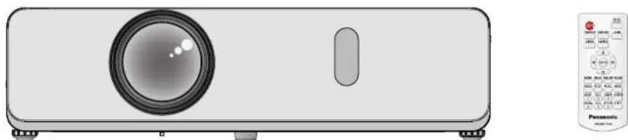
natural_image
Illustration of a projector with a circular lens and control panel (no text or symbols)
Thank you for purchasing this Panasonic Product.
Before operating this product, please read the instructions carefully, and save this manual ■ for future use.
Before using your projector, be sure to read "Read this first!" (→ pages 2 to 9).
Read this first!
WARNING: THIS APPARATUS MUST BE EARTHED.
WARNING: To prevent damage which may result in fire or shock hazard, do not expose this appliance to rain or moisture.
This device is not intended for use in the direct field of view at visual display workplaces. To avoid incommodding reflexions at visual display workplaces this device must not be placed in the direct field of view.
The equipment is not intended for used at a video workstation in compliance BildscharbV.
The sound pressure level at the operator position is equal or less than 70 dB (A) according to ISO 7779.
WARNING:
Remove the plug from the main socket when this unit is not in use for a prolonged period of time.1.
To prevent electric shock, do not remove cover. No user serviceable parts inside. Refer servicing to qualified service personnel.
Do not remove the earthing pin on the mains plug. This apparatus is equipped with a three prong earthing 3. type mains plug. This plug will only fit an earthing-type mains socket. This is a safety feature. If you are unable to insert the plug into the mains socket, contact an electrician. Do not defeat the purpose of the earthing plug.
CAUTION: To assure continued compliance, follow the attached installation instructions. This includes using the provided power cord and shielded interface cables when connecting to computer or peripheral devices. Also, any unauthorized changes or modifications to this equipment could void the user's authority to operate this device.
EEE Complies with Directive of Turkey.
WARNING: TO REDUCE THE RISK OF FIRE OR ELECTRIC SHOCK, DO NOT EXPOSE THIS PRODUCT TO RAIN OR MOISTURE.
WARNING
RISK OF ELECTRIC
SHOCK.DO NOT OPEN
AVERTISSEMENT: RISQUE DE CHOC ÉLECTRIQUE. NE PAS OUVRIR.
The lightning flash with arrowhead symbol, within an equilateral triangle, is intended to alert the user to the presence of uninsulated “dangerous voltage” within the product’s enclosure that may be of sufficient magnitude to constitute a risk of electric shock to persons.
The exclamation point within an equilateral triangle is intended to alert the user to the presence of important operating and maintenance (servicing) instructions in the literature accompanying the product.
This is a device to project images onto a screen, etc., and is not intended for use as indoor lighting in a domestic environment.
Directive 2009/125/EC
Importer's name and address within the European Union
Panasonic Marketing Europe GmbH
Panasonic Testing Center
Winsbergring 15, 22525 Hamburg, Germany
CAUTION (North/Middle/South America and Taiwan)
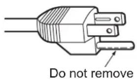
CAUTION: This equipment is equipped with a three-pin grounding-type power plug. Do not remove the grounding pin on the power plug. This plug will only fit a grounding-type power outlet. This is a safety feature. If you are unable to insert the plug into the outlet, contact an electrician. Do not defeat the purpose of the grounding plug.
text_image
Do not remove
FCC NOTICE (USA)
Model Number: PT-VW340Z, PT-VX410Z
Trade Name: Panasonic
Responsible Party: Panasonic Corporation of North America
Address: Two Riverfront Plaza, Newark, NJ 07102-5490
Telephone number: (877)803-8492
E-mail: projectorsupport@us.panasonic.com
This device complies with Part 15 of the FCC Rules.
Operation is subject to the following two conditions:
(1) This device may not cause harmful interference, and (2) this device must accept any interference received, including interference that may cause undesired operation.
To assure continued compliance, follow the attached installation instructions and do not make any unauthorized modifications.
CAUTION:
This equipment has been tested and found to comply with the limits for a Class B digital device, pursuant to Part 15 of the FCC Rules. These limits are designed to provide reasonable protection against harmful interference in a residential installation. This equipment generates, uses and can radiate radio frequency energy and, if not installed and used in accordance with the instructions, may cause harmful interference to radio communications. However, there is no guarantee that interference will not occur in a particular installation. If this equipment does cause harmful interference to radio or television reception, which can be determined by turning the equipment off and on, the user is encouraged to try to correct the interference by one of the following measures:
Reorient or relocate the receiving antenna.
Increase the separation between the equipment and receiver.
Connect the equipment into an outlet on a circuit different from that to which the receiver is connected.
Consult the dealer or an experienced radio/TV technician for help.
The user may find the booklet “Something About Interference” available from FCC local regional offices helpful.
FCC Warning:
To assure continued FCC emission limit compliance, follow the attached installation instructions. This includes using the provided power cord and shielded interface cables when connecting to computer or peripheral devices. Also, any unauthorized changes or modifications to this equipment could void the user's authority to operate this device.
NOTIFICATION (Canada)
This class B digital apparatus complies with Canadian ICES-003.
WARNING:
Not for use in a computer room as defined in the Standard for the Protection of Electronic Computer/Data Processing Equipment, ANSI/NFPA 75.
For permanently connected equipment, a readily accessible disconnect device shall be incorporated in the building installation wiring.
For pluggable equipment, the socket-outlet shall be installed near the equipment and shall be easily accessible.
Notice (USA only):
- This product has a High Intensity Discharge (HID) lamp that contains mercury. Disposal may be regulated in your community due to environmental considerations. For disposal or recycling information, please visit Panasonic website: http://www.panasonic.com/environmental or call 1-888-769-0149.
IMPORTANT: THE MOULDED PLUG (U.K. only)
FOR YOUR SAFETY, PLEASE READ THE FOLLOWING TEXT CAREFULLY.
This appliance is supplied with a moulded three pin mains plug for your safety and convenience. A 13 amp fuse is fitted in this plug. Should the fuse need to be replaced, please ensure that the replacement fuse has a rating of 13 amps and that it is approved by ASTA or BSI to BS1362.
Check for the ASTA mark for the BSI mark on the body of the fuse.
If the plug contains a removable fuse cover, you must ensure that it is refitted when the fuse is replaced. If you lose the fuse cover, the plug must not be used until a replacement cover is obtained. A replacement fuse cover can be purchased from an Authorised Service Center.
If the fitted moulded plug is unsuitable for the mains socket in your home, then the fuse should be removed and the plug cut off and disposed of safely. There is a danger of severe electrical shock if the cut off plug is inserted into any 13 amp socket.
If a new plug is to be fitted, please observe the wiring code as shown below. If in any doubt, please consult a qualified electrician.
WARNING: THIS APPLIANCE MUST BE EARTHED.
IMPORTANT: The wires in this mains lead are coloured in accordance with the following code:
Green - and - Yellow: Earth
Blue: Neutral
Brown: Live
As the colours of the wire in the mains lead of this appliance may not correspond with the coloured markings identifying the terminals in your plug, proceed as follows.
The wire which is coloured GREEN - AND - YELLOW must be connected to the terminal in the plug which is marked with the letter E or by the Earth symbol for coloured GREEN or GREEN - AND - YELLOW.
The wire which is coloured BLUE must be connected to the terminal in the plug which is marked with the letter N or coloured BLACK.
The wire which is coloured BROWN must be connected to the terminal in the plug which is marked with the letter L or coloured RED.
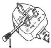
How to replace the fuse: Open the fuse compartment with a screwdriver and replace the fuse.
WARNING:
POWER ■
The wall outlet or the circuit breaker shall be installed near the equipment and shall be easily accessible when problems occur. If the following problems occur, cut off the power supply immediately.
Continued use of the projector in these conditions will result in fire or electric shock.
If foreign objects or water get inside the projector, cut off the power supply. ●
If the projector is dropped or the cabinet is broken, cut off the power supply. ●
- If you notice smoke, strange smells or noise coming from the projector, cut off the power supply.
Please contact an Authorized Service Center for repairs, and do not attempt to repair the projector yourself.
During a thunderstorm, do not touch the projector or the cable.
Electric shocks can result.
Do not do anything that might damage the power cord or the power plug.
If the power cord is used while damaged, electric shocks, short-circuits or fire will result.
- Do not damage the power cord, make any modifications to it, place it near any hot objects, bend it excessively, twist it, pull it, place heavy objects on top of it or wrap it into a bundle.
Ask an Authorized Service Center to carry out any repairs to the power cord that might be necessary.
Insert the power plug securely into the wall outlet.
If the plug is not inserted correctly, electric shocks or overheating will result.
Do not use anything other than the provided power cord. ●
Do not use the provided power cord for other electrical equipment. ●
Do not use plugs which are damaged or wall outlets which are coming loose from the wall. ●
Clean the power plug regularly to prevent it from becoming covered in dust.
Failure to observe this will cause a fire.
If dust builds up on the power plug, the resulting humidity can damage the insulation.
If not using the projector for an extended period of time, pull the power plug out from the wall outlet.
Pull the power plug out from the wall outlet and wipe it with a dry cloth regularly.
Do not handle the power plug with wet hands.
Failure to observe this will result in electric shocks.
Do not overload the wall outlet.
If the power supply is overloaded (ex., by using too many adapters), overheating may occur and fire will result.
ON USE/INSTALLATION ■
Do not place liquid containers on top of the projector.
If water spills onto the projector or gets inside it, fire or electric shocks will result.
If any water gets inside the projector, contact an Authorized Service Center.
Do not place the projector on soft materials such as carpets or sponge mats.
Doing so will cause the projector to overheat, which can cause burns, fire or damage to the projector.
Do not set up the projector in humid or dusty places or in places where the projector may come into contact with oily smoke or steam, ex. a bathroom.
Using the projector under such conditions will result in fire, electric shocks or components deterioration. Components deterioration (such as ceiling mount brackets) may cause the projector which is mounted on the ceiling to fall down.
Do not install this projector in a place which is not strong enough to take the full weight of the projector or on top of a surface which is sloped or unstable.
Failure to observe this will cause projector to fall down or tip over the projector, and severe injury or damage could result.
Do not place another projector or other heavy objects on top of the projector.
Failure to observe this will cause the projector to become unbalanced and fall, which could result in damage or injury. The projector will be damaged or deformed.
Installation work (such as ceiling mount bracket) should only be carried out by a qualified technician.
If installation is not carried out and secured correctly it can cause injury or accidents, such as electric shocks.
Do not use anything other than an authorized ceiling mount bracket.
Be sure to use the wire provided with the projector mount bracket for ceiling mount as an extra safety measure to prevent the projector from falling down (Install in a different location to the ceiling mount bracket).
Do not cover the intake port or the air exhaust port.
Doing so will cause the projector to overheat, which can cause fire or damage to the projector.
Do not place the projector in narrow, badly ventilated places.
- Do not place the projector on cloth or papers, as these materials could be drawn into the air intake port.
WARNING:
Do not place your hands or other objects close to the air exhaust port.
Doing so will cause burns or damage your hands or other objects.
- Heated air comes out of the air exhaust port. Do not place your hands or face, or objects which cannot withstand heat close to this port.
Do not look and place your skin into the lights emitted from the lens while the projector is being used.
Doing so can cause burns or loss of sight.
Strong light is emitted from the projector's lens. Do not look or place your hands directly into this light.
Be especially careful not to let young children look into the lens. In addition, turn off the power and disconnect the power plug when you are away from the projector.
Do not insert any foreign objects into the projector.
Doing so will cause fire or electric shocks.
- Do not insert any metal objects or flammable objects into the projector or drop them onto the projector.
Never attempt to remodel or disassemble the projector.
High voltages can cause fire or electric shocks.
- For any inspection, adjustment and repair work, please contact an Authorized Service Center.
Do not project an image with the lens cap attached.
Doing so can cause fire.
Do not allow metal objects, flammable objects, or liquids to enter inside of the projector. Do not allow the projector to get wet.
Doing so may cause short circuits or overheating, and result in fire, electric shock, or malfunction of the projector.
Do not place containers of liquid or metal objects near the projector. ●
If liquid enters inside of the projector, consult your dealer. ●
Particular attention must be paid to children. ●
Use the ceiling mount bracket specified by Panasonic.
Defects in the ceiling mount bracket will result in falling accidents.
- Attach the supplied safety cable to the ceiling mount bracket to prevent the projector from falling down.
ACCESSORIES ■
Do not use or handle the batteries improperly, and refer to the following.
Failure to observe this will cause burns, batteries to leak, overheat, explode or catch fire.
Use AAA/R03 o ● r AAA/LR03 batteries.
Do not use unspecified batteries.
- Do not heat the batteries or place them into water or fire.
Do not allow the + and - terminals of the batteries to come into contact with metallic objects such as necklaces or hairpins.
● Store the batteries in a plastic bag and keep them away from metallic objects.
Make sure the polarities (+ and -) are correct when inserting the batteries.
- Do not use a new battery together with an old battery or mix different types of batteries.
Do not use batteries with the outer cover peeling away or removed.
● Insulate the battery using tape or something similar before disposal.
Do not allow children to reach the batteries (AAA/R03 or AAA/LR03 type).
The battery can cause personal injury if swallowed.
If the battery fluid leaks, do not touch it with bare hands, and take the following measures if necessary.
● Battery fluid on your skin or clothing could result in skin inflammation or injury.
Rinse with clean water and seek medical advice immediately.
● Battery fluid coming in contact with your eyes could result in loss of sight.
In this case, do not rub your eyes. Rinse with clean water and seek medical advice immediately.
WARNING:
Do not disassemble the lamp unit.
If the lamp breaks, it could cause injury.
Lamp replacement
The lamp has high internal pressure. If improperly handled, an explosion and severe injury or accidents will result.
● The lamp can easily explode if struck against hard objects or dropped.
Do not allow infants or pets to touch the remote control unit.
- Keep the remote control unit out of the reach of infants and pets after using it.
Do not use the supplied power cord with devices other than this projector.
- Using the supplied power cord with devices other than this projector may cause short circuits or overheating, and result in electric shock or fire.
Remove the depleted batteries from the remote control promptly.
● Leaving them in the unit may result in fluid leakage, overheating, or explosion of the batteries.
CAUTION:
POWER ■
When disconnecting the power cord, be sure to hold the power plug and power connector.
If the power cord itself is pulled, the lead will become damaged, and fire, short-circuits or serious electric shocks will result.
When not using the projector for an extended period of time, disconnect the power plug from the wall outlet and remove the batteries from the remote control.
Disconnect the power plug from the wall outlet before carrying out any cleaning and replacing the unit.
Electric shocks can result if this is not done.
ON USE/INSTALLATION ■
Do not place heavy objects on top of the projector.
Failure to observe this will cause the projector to become unbalanced and fall, which could result in damage or injury. The projector will be damaged or deformed.
Do not put your weight on this projector.
You could fall or the projector could break, and injury will result.
Be especially careful not to let young children stand or sit on the projector. ●
Do not place the projector in extremely hot locations.
Doing so will cause the outer casing or internal components to deteriorate, or result in fire.
● Take particular care in locations exposed to direct sunlight or near stoves.
Always disconnect all cables before moving the projector.
Moving the projector with cables still attached can damage the cables, which will cause fire or electric shocks to occur.
Never plug headphones and earphones into VARIABLE AUDIO OUT jack.
Excessive sound pressure from earphones and headphones can cause hearing loss.
ACCESSORIES ■
Do not use the old lamp unit.
If used it could cause lamp explosion.
If the lamp has broken, ventilate the room immediately. Do not touch or bring your face close to the broken pieces.
Failure to observe this will cause the user to absorb the gas which was released when the lamp broke and which contains nearly the same amount of mercury as fluorescent lamps, and the broken pieces will cause injury.
If you believe that you have absorbed the gas or that the gas has got into your eyes or mouth, seek medical advice immediately.
Ask your dealer about replacing the lamp unit and check the inside of the projector.
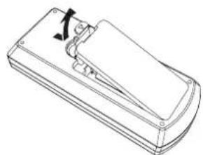
To remove the battery
Press the guide and lift the cover. 2. Remove the batteries.
natural_image
Line drawing of a rectangular electronic device with a handle and mounting bracket (no text or symbols)
natural_image
Diagram of a rectangular electronic device with three ports and directional arrows indicating rotation or movement (no text or symbols)
Brazil Only Brasil Apenas
natural_image
Line drawing of a flatboard-shaped object with a handle and mounting base (no text or symbols)
natural_image
Diagram of a remote control box with two buttons and directional arrows indicating rotation (no text or symbols)
Trademarks ■
Windows® Windows Vista® and Internet Explorer® are registered trademarks or trademarks of Microsoft Corporation in the United States and other countries.
• Macintosh and Mac, Mac OS, OS X, and Safari are trademarks of Apple Inc., registered in the United States and other countries.
Please note that the operating instructions do not include the ® and ™ symbols.
Illustrations in these operating instructions ■
- Note that illustrations of the projector and screens may differ from the ones you actually see.
Page references ■
- In these instructions, references to pages are indicated as: (→ page 00).
term
- In these instructions, the "Wireless remote control unit" accessory is referred to as the "Remote control".
Features of the Projector
Quick Steps
Auto Setup Function
This function executes [SHIFT], [CLOCK PHASE], [DOT CLOCK] at the same time by pressing the button.
Direct Power Off Function
With the Direct Power Off function, you can disconnect the power cord from the wall outlet or turn off the breaker even during projection.
Wired LAN Function
This function allows you to project an image on a computer as well as operate and manage the projector via network.
Useful Functions for Presentations
The digital zoom function allows you to focus on the crucial information during a presentation.
The MIC function and 10 W audio output allows you to make a presentation without any external audio equipment.
For details, see the corresponding pages.
Set up your projector. 1.
(→ page 25)
Connect with other devices. 2.
(→ page 29)
Connect the power cord. 3.
(→ page 34)
Power on. 4.
(→ page 36)
Make initial settings. 5.
(→ page 19)
Take this step when you power on for the first time after purchasing the projector.
Select the input signal. 6.
(→ page 38)
Adjust the image.
(→ page 38)
Contents
Be sure to read "Read this first!" from page 2.
Read this first! 2
Chapter 1 Preparation
Precautions for use 14
Cautions when transporting 14
Cautions when installing 14
Security 15
Disposal 15
Cautions on use 16
Accessories 17
Contents of the supplied CD-ROM 18
Optional accessories 18
Start-up display 19
Initial setting (display language) 19
Initial setting (projector setup) 19
About your projector 20
Remote control 20
Projector body 21
Using the remote control 23
Inserting and Removing batteries 23
Setting Remote control ID numbers 23
Chapter 2 Getting Started
Setting up 25
Installation mode 25
Parts for ceiling mount (Optional) 25
Screen size and throw distance 26
Adjusting adjustable feet 28
Connecting 29
Before connecting to the projector 29
Connecting example : AV equipment 31
Connecting example : Computers .... 31
Connecting example: Audio 32
Chapter 3 Basic Operations
Powering on/off 34
Connecting the power cord 34
ON(G)/STANDBY(R) indicator.... 35
Powering On the Projector 36
Making adjustments and selections 36
Powering Off the Projector 37
Direct Power Off function 37
Projecting 38
Selecting the input signal 38
How to adjust the state of the image 38
Basic operations by using the remote control ..... 39
Using the AUTO SETUP function 39
Using the KEYSTONE button 39
Switching the input signal 40
Using the FUNCTION button 40
Using the FREEZE function 40
Using the AV MUTE function 41
Using the P-TIMER function 41
Using the DIGITAL ZOOM function 41
Controlling the volume of the speaker 42
Using the MUTE function 42
Using the P IN P function 43
Chapter 4 Settings
Navigating through the menu 45
Resetting adjustment values to the factory default ...46
Main menu 46
Sub menu 47
[PICTURE MODE] 49
[CONTRAST] 49
[BRIGHTNESS] 50
[COLOR] 50
[TINT] 50
[SHARPNESS] 50
[COLOR TEMPERATURE] 51
[IRIS] 51
[ADVANCED MENU] 51
[DAYLIGHT VIEW] 51
[DIGITAL CINEMA REALITY] 52
[NOISE REDUCTION] 52
[TV-SYSTEM] 52
[RGB/YPBPR]/[RGB/YCBr] 53
[REALTIME KEYSTONE] 54
[KEYSTONE] 54
[SHIFT]....56
[DOT CLOCK]...... 56
[CLOCK PHASE] 56
[OVER SCAN] 57
[ASPECT] 57
[FRAME LOCK] 58
[LANGUAGE] 59
[ON-SCREEN DISPLAY] 60
[HDMI SIGNAL LEVEL] 61
[CLOSED CAPTION SETTING] 61
[SCREEN SETTING] 62
[STARTUP LOGO] 62
[AUTO SETUP SETTING] 63
[SIGNAL SEARCH] 63
[BACK COLOR] 63
[WIDE MODE] 63
[SXGA MODE] 63
[P-TIMER]......64
Contents
[P IN P]....65
[OTHER FUNCTIONS] 65
[STATUS]....66
[COMPUTER2 SELECT]......66
[PROJECTOR ID] 66
[INITIAL START UP] 67
[PROJECTION METHOD] 67
[HIGH ALTITUDE MODE] 67
[LAMP POWER] 68
[ECO MANAGEMENT] 68
[EMULATE]....69
[FUNCTION BUTTON] 70
[AUDIO SETTING] 70
[TEST PATTERN] 72
[FILTER COUNTER].... 72
[INITIALIZE ALL] 72
[PASSWORD] 73
[PASSWORD CHANGE] 73
[TEXT DISPLAY] 74
[TEXT CHANGE] 74
[MENU LOCK] 74
[MENU LOCK PASSWORD] 74
[CONTROL DEVICE SETUP] 75
[WIRED LAN] 76
[NAME CHANGE] 77
[NETWORK CONTROL] 77
[AMX D. D.] 77
[Crestron Connected(TM)] 77
[STATUS]....78
[INITIALIZE]....78
Network connections 79
Accessing from the Web browser 80
Chapter 5 Maintenance
LAMP and WARNING Indicators 94
Managing the indicated problems 94
Replacement 95
Before performing maintenance/replacement ..... 95
Maintenance 95
Replacing the unit 95
Attaching the Lens Cap 98
Troubleshooting 99
Chapter 6 Appendix
PJLink protocol 101
Control commands via LAN 102
Serial terminal 104
Two window display combination list 107
List of compatible signals 108
Specifications 110
12 - ENGLISH
Dimensions 112
Ceiling mount bracket safeguards.... 113
Index 114
Chapter 1 Preparation
This chapter describes things you need to know or check before using the projector.
Precautions for use
Cautions when transporting
When transporting the projector, hold it securely by its bottom and avoid excessive vibration and impacts. Doing so may damage the internal parts and result in malfunctions.
Do not transport the projector with the adjustable feet extended. Doing so may damage the adjustable feet.
Cautions when installing
Do not set up the projector outdoors. ■
The projector is designed for indoor use only.
Do not use under the following conditions. ■
Places where vibration and impacts occur such as in a car or vehicle: Doing so may damage the internal parts and result in malfunctions.
Near the exhaust of an air conditioner or near lights (studio lamps, etc.) where temperature changes greatly (Operating environment ➤ page 111): Doing so may shorten the life of the lamp or result in deformation of the outer case and malfunctions.
Near high-voltage power lines or near motors: Doing so may interfere with the operation of the projector.
Be sure to ask a specialized technician when installing the product to a ceiling. ■
This requires an optional ceiling mount bracket.
Model No.: ET-PKV100H (for high ceilings), ET-PKV100S (for low ceilings),
ET-PKV101B (Projector Mount Bracket).
■ When using the projector in the elevation of below 1 400 m (4 593'), make sure [HIGH ALTITUDE MODE] is set to [OFF].
Failure to do so may shorten the life of the internal parts and result in malfunctions.
■ When using the projector in the elevation of above 1 400 m (4 593') and below 2 000 m (6 562'), make sure [HIGH ALTITUDE MODE] is set to [HIGH1].
Failure to do so may shorten the life of the internal parts and result in malfunctions.
■ When using the projector in the elevation of above 2 000 m (6 562') and below 2 700 m (8 858'), make sure [HIGH ALTITUDE MODE] is set to [HIGH2].
Failure to do so may shorten the life of the internal parts and result in malfunctions.
■ Do not install the projector at elevations of 2 700 m (8 858') or higher above sea level.
Failure to do so may shorten the life of the internal parts and result in malfunctions.
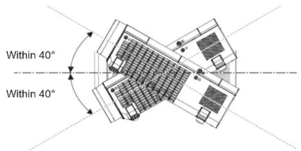
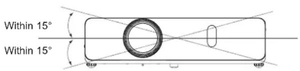
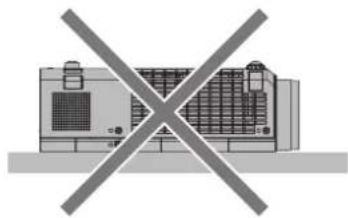
Do not tilt the projector or place it on its side.
Do not tilt the projector body more than approximately ±40 degrees vertically or ±15 degrees horizontally. Over tilting may result in shortening the life of the components.
text_image
Within 40°
Within 40°
text_image
Within 15°
Within 15°
Cautions when setting the projectors ■
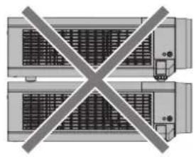
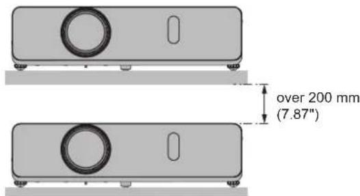
Do not stack the projectors.
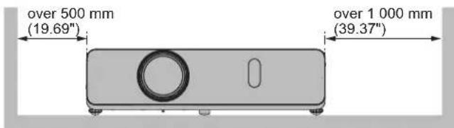
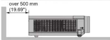
Do not block the ventilation ports (intake and exhaust) of the projector.
Avoid heating and cooling air from the air conditioning system directly blow to the ventilation ports (intake and exhaust) of the projector.
natural_image
Pure diagram of a cross-shaped structure with no text, numbers, or symbols
natural_image
Diagram of a device with a crossed-out X symbol, no text or labels present
text_image
over 500 mm
(19.69")
over 1 000 mm
(39.37")
text_image
over 200 mm
(7.87"
text_image
over 500 mm
(19.69")
Do not install the projector in a confined space.
When placing the projector in a confined space, a ventilation and/or air conditioning system is required. Exhaust heat may accumulate when the ventilation is not enough, triggering the protection circuit of the projector.
Security
Take safety measures against following incidents.
Personal information being leaked via this product.
Unauthorized operation of this product by a malicious third party.
Interfering or stopping of this product by a malicious third party.
Security instruction (→ pages 73, 89)
Make your password as difficult to guess as possible.
Change your password periodically.
Panasonic or its affiliate company never inquires a password directly to a customer. Do not tell your password in case you receive such an inquiry.
The connecting network must be secured by firewall or others.
Set a password for web control and restrict the users who can log in.
Disposal
When disposing of the product, ask your local authority or dealer about the correct methods of disposal.
The lamp contains mercury. When disposing of the used lamp unit, ask your nearest local authorities or dealer about proper disposal of the unit.
Dispose of used batteries according to the instructions or your local disposal rule or guidelines.
Cautions on use
To get a good picture quality ■
Draw curtains or blinds over windows and turn off any lights near the screen to prevent outside light or light from indoor lamps from shining onto the screen.
Depending on where the projector is used, heated air from an exhaust port or warm or cold air from an air conditioner can cause a shimmering effect on screen.
The lens of projector is affected by the heat from the luminous source. Because of this, the focusing may not be stable right after the power is turned on. Focusing is stabled after projecting image for 30 minutes and longer.
Do not touch the surface of the projector lens with your bare hands. ■
If the surface of the projection lens becomes dirty from fingerprints or anything else, this will be magnified and projected onto the screen.
Attach the supplied lens cap to the projection lens when you do not use the projector.
LCD Panel ■
The display unit of this projector comprises three LCD panels. Although an LCD panel is a product of high-precision technology, some of the pixels on the projected image may be missing or constantly lit. Please note that this is not a malfunction.
Displaying a still image for a longer time may result in an after-image on the LCD panels. If this happens, display the all white screen in the test pattern for an hour or more.
Optical components ■
Operating the projector in an environment with high temperature or heavy exposure to dust or tobacco smoke will reduce the service life of the optical components, such as the LCD panel and polarizing plate, and may necessitate their replacement within less than one year of use. For details, consult your dealer.
Lamp ■
The luminous source of the projector is a mercury lamp with high internal pressure.
A high pressure mercury lamp has following characteristics.
The brightness of the lamp will decrease by duration of usage.
The lamp may burst with sound or shorten life by shock or chipping.
The life of the lamp varies greatly depending on individual specificities and usage conditions. In particular, continuous use over 12 hours and frequent on/off switching of the power greatly deteriorate the lamp and affect the lamp life.
In rare cases, the lamp burst shortly after the projection.
- The risk of bursting increases when the lamp is used beyond its replacement cycle. Make sure to replace the lamp unit consistently. ("When to replace the lamp unit" (→ page 97))
- If the lamp bursts, gas contained inside of the lamp is released in a form of smoke.
It is recommended to store replacement lamps for contingency.
- It is recommended to have authorized engineer or your dealer replace the lamp unit.
Accessories
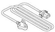
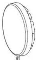
Make sure the following accessories are provided with your projector. Numbers enclosed < > show the number of accessories.
Wireless remote control unit <1>
(N2QAYA000070) (N2QAYA000071)
PT-VW340Z
CD ROM <1>
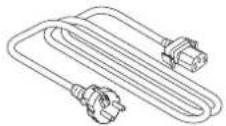
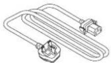
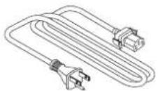
Power cord (TXFSX02UXRZ)
AAA/R03 or AAA/LR03 battery <2>
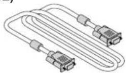
(TXFSX02UYAZ) VGA cable <1>
(K1HY15YY0012)
(TXFSX02UFEZ) String <1>
(6103504711)
(TXFSX02UTRZ) Lens cap <1>
(TKKL5568)
Attention
After unpacking the projector, discard the power cord cap and packaging material properly.
Do not use the supplied power cord for devices other than this projector.
For lost accessories, consult your dealer.
Store small parts in an appropriate manner, and keep them away from young children.
Note
- The type and number of the power cord depend on the country in which you purchased the product. The model numbers of accessories are subject to change without prior notice.
Contents of the supplied CD-ROM
The contents of the supplied CD-ROM are as follow.
Instruction/list (PDF) Operating Instructions – Functional Manual Operating Instructions – Multi Projector Monitoring & Control Software Operating Instructions – Logo Transfer Software List of compatible projector models T This is a list of projectors that are compatible with the software, and their restrictions. Software Multi Projector Monitoring & Control Software (Windows) This software allows you to monitor and control multiple projectors connected to the LAN. Logo Transfer Software (Windows) T This software allows you to create original images, such as company logos to be displayed when projection starts, and transfer them to the projector.
Optional accessories
Options Model No. Ceiling Mount Bracket ET-PKV100H (for high ceilings),ET-PKV100S (for low ceilings) Projector Mount Bracket ET-PKV101B Replacement Lamp Unit ET-LAV300 Replacement Filter Unit ET-RFV300
Note
The model numbers of optional accessories are subject to change without prior notice.
Start-up display
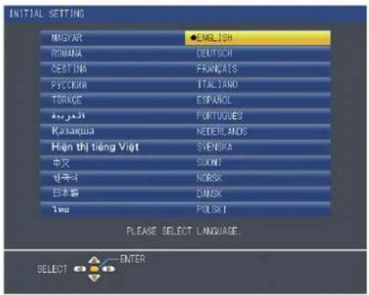
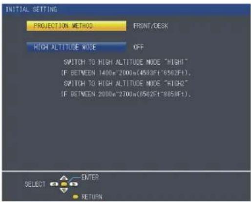
When the projector is switched on for the first time after purchase as well as when [INITIALIZE ALL] is executed in the [PROJECTOR SETUP] menu, then the initial setting screen is displayed. Set them in accordance with circumstances. In other occasions, you can change the settings by menu operations.
Initial setting (display language)
Select the language to show on the screen.
Press 1) ▲▼◀▶ to select the display language.
text_image
INITIAL SETTING
MAGYAR ●ENGLISH
ROMANA DEUTSCH
SESTINA FRAUÇATS
PYCCKIN ITALAND
TORKCE ESPACOL
KASAKWA FORTUGUES
Higner thị tiếng Việt SVENSKA
中文 SUOMI
한국사 NORSK
日本語 DANSK
1996 POLSKI
PLEASE SELECT LANGUAGE:
SELECT ENTER
Press the button to proceed to the initial setting.2)
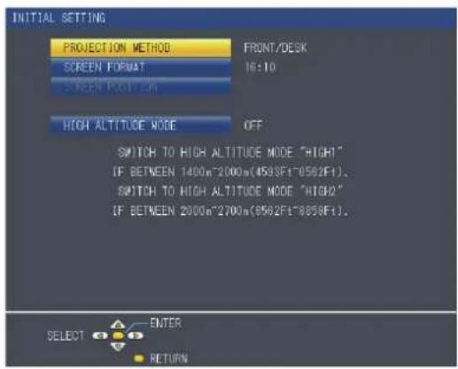
Initial setting (projector setup)
Set each item.
Press 1) ▲▼ to select an item.
Press 2) ◀▶ to switch the setting.
PT-VW340Z
text_image
INITIAL SETTING
PROJECTION METHOD FRONT/DESK
SCREEN FORMAT 16:10
SCREEN FOOTRUN
HIGH ALTITUDE MODE OFF
SWITCH TO HIGH ALTITUDE MODE "HIGH"
IF BETWEEN 1400m^2000m(4583Ft^8582Ft).
SWITCH TO HIGH ALTITUDE MODE "HIGH2"
IF BETWEEN 2000m^2700m(8582Ft^8583Ft).
SELECT ENTER
Return
PT-VX410Z
text_image
INITIAL SETTING
PROJECTION METHOD FRONT/DESK
HIGH ALTITUDE MODE OFF
SWITCH TO HIGH ALTITUDE MODE "RIGHT"
[IF BETWEEN 1400m^2000m(4503F1^8562F1),
SWITCH TO HIGH ALTITUDE MODE "HIGH2"
[IF BETWEEN 2000m^2700m(8562F1^8856F1)。
SELECT ENTER
RETURN
[PROJECTION METHOD] (→page 67)
[SCREEN FORMAT] (Only for PT-VW340Z → page 62)
[SCREEN POSITION] (Only for PT-VW340Z → page 62)
[HIGH ALTITUDE MODE] (→ page 67)
Confirm the setting value and complete the initial setting.
Note
If you press the button on the initial setting screen, you can go back to the previous screen.
To continue operations after completed the initial settings, refer to "Selecting the input signal" (→ page 38).
About your projector
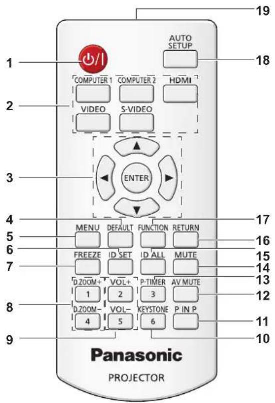
Remote control
text_image
19
18
COMPUTER 1 COMPUTER 2 HDMI
VIDEO S-VIDEO
ENTER
3
4
MENU DEFAULT FUNCTION RETURN
5
FREEZE ID SET ID ALL MUTE
6
D.ZOOM+ VOL+ P-TIMER AV MUTE
7
1 D.ZOOM- VOL- KEYSTONE P IN P
8
4 5 6
Panasonic
PROJECTOR
10
11
12
13
14
15
16
17
18
AUTO SETUP
<1 ⏻/|> Button
Turn the projector on or off. (→ pages 36,37)
Input Selection Buttons: , 2
, , , .
These buttons are used to select the input signal.
(→page 40)
▲▼◀▶3 Buttons, Button
Navigate the MENU display.
Button4
Resets the content of the sub-menu to the factory default.
(→page 46)
Button5
Open or close the On-Screen Menu. (→page 45)
Button6
Sets the ID number of the remote control to use for a system using multiple projectors.
Button7
Pauses the projected image and mute the audio temporarily. (→ page 40)
8 Buttons
Zoom in and out the images. (→ page 41)
9 Buttons
Adjust the volume of the speaker. (→page 42)
10 Button
Correct keystone distortion. (→page 39)
11 Button (Only for PT-VW340Z)
Operate the P IN P function.
12 Button
Used to turn off the audio and video temporarily.
(→page 41)
13 Button
Operate the P-timer function. (→page 41)
14 Button
Used to mute the audio. (→page 42)
15 Button
Used to simultaneously control all the projectors with one remote control for a system using multiple projectors.
16 Button
Return to the previous menu or cancel the setting.
17 Button
Assigns a frequently used operation as a shortcut button.
18 Button
Automatically adjusts the image display position while projecting the image. (→page 39)
19 Remote control signal emitter
Attention
Do not drop the remote control.
Avoid contact with liquids.
Do not attempt to modify or disassemble the remote control.
Note
- The remote control can be used within a distance of about 7 m (22.97") if pointed directly at the remote control signal receiver. The remote control can control at angles of up to ±30° vertically and ±30° horizontally, but the effective control range may be reduced.
- If there are any obstacles between the remote control and the remote control signal receiver, the remote control may not operate correctly.
- You can operate the projector by reflecting the remote control signal on the screen. The operating range may differ due to the loss of light caused by the properties of the screen.
- When the remote control signal receiver is lit with a fluorescent light or other strong light source, the projector may become inoperative. Set the projector as far from the luminous source as possible.
Projector body

text_image
Technical diagram of a projector with numbered parts and exploded view showing internal structure
WARNING
Keep your hands and other objects away from the air exhaust port.
- Keep your hand and face away.
- Do not insert your finger.
- Keep heat-sensitive articles away.
Heated air from the air exhaust port can cause burns or external damage.
Zoom ring (Back)1
Adjust the zoom.
Control Panel and Indicators (▶ page 22)
Lamp cover (▶ page 97)
The lamp unit is located inside.
Projection Lens4
Focus ring (Front)5
Adjust the focus.
Remote control signal receiver6
Air exhaust port7
Speaker8
terminal 9
Connect the supplied power cord.
Rear terminals (page 22)
Air intake port / Air filter cover (11 → page 95)
The air filter unit is inside.
Adjustable feet 12
Adjust the projection angle.
Security Chain Hook 13
Attaches a burglar prevention cable, etc.
Attention
\- Do not block the ventilation ports (intake and exhaust) of the projector.
Control panel and Indicators ■

text_image
ON(G)/
STANDBY(R)
INPUT SELECT
9
LAMP
ENTER
WARNING
MENU
AUTO SETUP
10
6
7
8
1 <|}/|> button
Turns the projector on/off.
2 indicator
Displays the status of the power.
3 indicator
Lights red when the projection lamp reaches its end of life.
4 indicator
Indicates the abnormal conditions of the projector.
5 Ambient Luminance sensor
Detects room's light and select proper image quality.
6 button
Displays the menu screen. (→ page 45)
7 button
Executes the selected item.
8 ▲▼◀▶ buttons
Navigate the MENU screen.
Adjust the volume level (◀▶).
9 button
Executes the auto setup function.
■Rear terminals

text_image
1
2
3
4
COMPUTER 1 IN
COMPUTER 2 IN/1 OUT
SERIAL IN
VIDEO IN
HDMI
IN
MIC IN
VARIABLE
AUDIO OUT
S-VIDEO IN
LAN
5
6
7
8
9
10
11
12
terminal1
This is the terminal to input RGB or YP_BP_R/YC_BC_R signals.
terminal
This is the terminal to input RGB signals or output the RGB/YC _B C _R /YP _B P _R signals to external monitor.
terminal3
This is the terminal to input HDMI signals.
terminal4
This is the LAN terminal to connect to the network.
terminal5
This is the RS-232C compatible terminal to externally control the projector by connecting a computer.
terminal6
This is the terminal to input video signals.
terminal7
This is the terminal to input audio signals.
There are a left (L) terminal and a right (R) terminal.
terminal8
This is the terminal to input audio signals.
terminal9
This is the terminal to input audio signals. Or connect the MIC to this terminal.
10 terminal
This is the terminal to output audio signals input to the projector.
11 terminal
This is the terminal to input s-video signals.
12 Security slot
Attach the commercial shackle lock, manufactured by Kensington, to protect your projector. Compatible with the Kensington MicroSaver Security System.
Attention
\- When a LAN cable is directly connected to the projector, the network connection must be made indoors.
22 - ENGLISH
Using the remote control
Inserting and Removing batteries

natural_image
Line drawing of a mechanical device with a handle and mounting bracket (no text or symbols)
Fig. 1

natural_image
Line drawing of a rectangular electronic device casing with three buttons and mounting holes (no text or symbols)
Fig. 2
Open the cover. (Fig. 1)1)
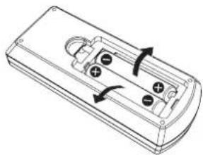
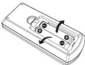
2) Insert batteries and close the cover (Insert the ⬤ side first.) (Fig. 2)
When removing the batteries, perform the steps in reverse order.
Setting Remote control ID numbers
When you use the system with multiple projectors, you can operate all the projectors simultaneously or each projector individually using single remote control, if unique ID number is assigned to each projector.
After setting the ID number of the projector, set the same ID number to the remote control.
The factory default ID number of the projector is set to [ALL]. When using a single projector, press the button on the remote control. Also, you can control a projector by pressing the button on the remote control even if you do not know the projector ID.
How to set
Press the button on the remote control.1)
Within five seconds, press the one digit ID number set on the projector using the number (<1> - <6>)2) buttons.
\- If you press the button, you can control the projectors regardless of the ID number setting of the projector.
Attention
- Since the ID number of the remote control can be set without the projector, do not press the button on the remote control carelessly. If the button is pressed and no number (<1> - <6>) buttons are pressed within five seconds, the ID number returns to its original value before the button was pressed.
- The ID number set on the remote control will be stored unless it is set again. However, it will be erased if the remote control is left with dead batteries. Set the same ID number again when the batteries are replaced.
Note
\- Set the ID number of the projector from the [PROJECTOR SETUP] menu → [PROJECTOR ID]. (→ page 66)
Chapter 2 Getting Started
This chapter describes things you need to do before using the projector such as the setup and connections.
Setting up
Installation mode
There are four ways to set up the projector. Set the [PROJECTOR SETUP] menu → [PROJECTION METHOD] (→ page 67) depending on the installation location.
Mounting on the ceiling and projecting forward Setting on a desk/floor and projecting from rear(Using the translucent screen) Menu item Method Menu item Method [PROJECTION METHOD] [FRONT/CEILING] [PROJECTION METHOD] [REAR/DESK]
Mounting on the ceiling and projecting from rear(Using the translucent screen) Setting on a desk/floor and projecting forward Menu item Method Menu item Method [PROJECTION METHOD] [REAR/CEILING] [PROJECTION METHOD] [FRONT/DESK]
Parts for ceiling mount (Optional)
You can install the projector on the ceiling by using the optional ceiling mount bracket (ET-PKV100H: for high ceiling, ET-PKV100S: for low ceiling), and the optional projector mount bracket ET-PKV101B.
Use only the ceiling mount brackets specified for this projector.
\- Refer to the Installation Instructions for the ceiling mount bracket when you install the bracket and the projector.
Attention
\- To ensure projector performance and security, installation of the ceiling mount bracket must be carried by your dealer or a qualified technician.
Screen size and throw distance
Refer to the screen size and projection distances to install the projector. Image size and image position can be adjusted in accordance with the screen size and screen position.

text_image
Projected image
SH
SD
SW

text_image
SH
Screen
L (LW/LT)

text_image
SW
L (LW/LT)
Screen
L (LW/LT) *1 Projection distance (m) SH Image height (m) SW Image width (m) H Distance from the center of lens to the image lower end (m) SD Projected image size (m)
LW : Minimum distance \*1
LT : Maximum distance
Attention
\- Before installing, please read "Precautions for Use" (→ pages 14 to 18).
Projection distance
For PT-VW340Z
All measurements below are approximate and may differ slightly from the actual measurements. (Unit: m)
Projection size For 4:3 aspect ratio For 16:9 aspect ratio For 16:10 aspect ratio Screen diagonal (SD) Minimum distance (LW) Maximum distance (LT) Height position (H) Minimum distance (LW) Maximum distance (LT) Height position (H) Minimum distance (LW) Maximum distance (LT) Height position (H) 0.76 (30") 0.8 1.4 0.00 09 0.8 1.2 0.007 0.7 1.2 0.008 1.02 (40") 1.1 1.8 0.012 1.0 1.7 0.010 1.0 1.6 0.011 1.27 (50") 1.4 2.3 0.01 15 1.3 2.1 0.012 1.3 2.0 0.013 1.52 (60") 1.7 2.8 0.018 1.6 2.5 0.015 1.5 2.5 0.016 1.78 (70") 2.0 3.3 0.021 1.8 3.0 0.017 1.8 2.9 0.019 2.03 (80") 2.3 3.7 0.02 24 2.1 3.4 0.020 2.0 3.3 0.022 2.29 (90") 2.6 4.2 0.02 27 2.3 3.8 0.022 2.3 3.7 0.024 2.54 (100") 2.9 4.7 0.030 2.6 4.2 0.025 2.5 4.1 0.027 3.05 (120") 3.5 5.6 0.037 3.1 5.1 0.030 3.1 4.9 0.032 3.81 (150") 4.3 7.0 0.046 3.9 6.4 0.037 3.8 6.2 0.040 5.08 (200") 5.8 9.4 0.061 5.3 8.5 0.050 5.1 8.3 0.054 6.35 (250") 7.3 11.7 0.076 6.6 10.6 0.062 6.4 10.3 0.067 7.62 (300") 8.7 14.0 0.091 7.9 12.7 0.075 7.7 12.4 0.081
For PT-VX410Z
All measurements below are approximate and may differ slightly from the actual measurements. (Unit: m)
Projection size For 4:3 aspect ratio For 16:9 aspect ratio Screen diagonal (SD) Minimum distance (LW) Maximum distance (LT) Height position (H) Minimum distance (LW) Maximum distance (LT) Height position (H) 0.76 (30") 0.7 1.1 0.046 0.8 1.2 0.037 1.02 (40") 0.9 1.5 0.061 1.0 1.7 0.050 1.27 (50") 1.2 1.9 0.076 1.3 2.1 0.062 1.52 (60") 1.4 2.3 0.091 1.6 2.5 0.075 1.78 (70") 1.7 2.7 0.107 1.8 3.0 0.087 2.03 (80") 1.9 3.1 0.122 2.1 3.4 0.100 2.29 (90") 2.2 3.5 0.137 2.3 3.8 0.112 2.54 (100") 2.4 3.9 0.152 2.6 4.2 0.125 3.05 (120") 2.9 4.7 0.183 3.1 5.1 0.149 3.81 (150") 3.6 5.8 0.229 3.9 6.4 0.187 5.08 (200") 4.8 7.8 0.305 5.3 8.5 0.249 6.35 (250") 6.0 9.7 0.381 6.6 10.6 0.311 7.62 (300") 7.3 11 0.457 7.9 12.7 0.374
Any other projection distance can be obtained according to the screen dimensions (m) using the following calculations.
The calculated distance may contain a certain error.
If the screen dimensions are written as "SD",
For PT-VW340Z
For 4:3 aspect ratio For 16:9 aspect ratio For 16:10 aspect ratio Screen height (SH) = SD(m) × 0.6 = SD(m) × 0.490 = SD(m) × 0.530 Screen width (SW) = SD(m) × 0.8 = SD(m) × 0.872 = SD(m) × 0.848 Minimum distance (LW) = 1.1458 × SD(m) - 0.0294 = 1.0402 × SD(m) - 0.0294 = 1.0121 × SD(m) - 0.0294 Maximum distance (LT) = 1.8467 × SD(m) - 0.0319 = 1.6765 × SD(m) - 0.0319 = 1.6312 × SD(m) - 0.0319
For PT-VX410Z
For 4:3 aspect ratio For 16:9 aspect ratio Screen height (SH) = SD(m) × 0.6 = SD(m) × 0.490 Screen width (SW) = SD(m) × 0.8 = SD(m) × 0.872 Minimum distance (LW) = 0.9548 × SD(m) - 0.0294 = 1.0403 × SD(m) - 0.0294 Maximum distance (LT) = 1.5389 × SD(m) - 0.0319 = 1.6766 × SD(m) - 0.0319
Adjusting adjustable feet
Lift the front of the projector and press the feet lock latches on both side of the projector.
Release the feet lock latches to lock the adjustable feet and rotate the adjustable feet to a proper height and tilt.
You can turn the adjustable feet to extend them. You can turn them in the opposite direction to contract them.
(You can adjust the projection angle vertically.)

text_image
Feet lock
Feet lock latches
Adjustable range
Adjustable feet : 43.0 mm (1.693")
Attention
- Heated air comes out of the air exhaust port while the lamp is lit. Do not touch the air exhaust port directly when you adjust the adjustable feet.
- If keystone distortion occurs on the projected image, perform [KEYSTONE] from the [POSITION] menu. (→page 54)
Note
Screw up the adjustable feet, and an audible click will be heard as the limit.
Connecting
Before connecting to the projector
\- Before connecting, carefully read the operating instructions for the external device to be connected.
Turn off the power switch of the devices before connecting cables.
\- Take note of the following points before connecting the cables. Failure to do so may result in malfunctions.
\- When connecting a cable to a device connected to the projector or the projector itself, touch any nearby metallic objects to eliminate static electricity from your body before performing work.
\- Do not use unnecessarily long cables to connect to a device connected to the projector or to the projector body. The longer the cable, the more it is susceptible to noise. Since using a cable while it is wound makes it act like an antenna, it is more susceptible to noise.
\- When connecting cables, connect GND first, then insert the connecting terminal of the connecting device in a straight manner.
\- If any connection cable is not supplied with the device, or if no optional cable is available for connection of the device, prepare a necessary system connection cable to suit the device.
\- Video signals containing too much jitter may cause the images on the screen to randomly wobble or wafture. In this case, a time base corrector (TBC) must be connected.
The projector accepts VIDEO signals, S-VIDEO signals, YC_BC_R/YP_BP_R signals and analog RGB signals (synchronous signals are TTL level), and digital signal.
Some computer models are not compatible with the projector.
\- When using long cables to connect with each of equipment to the projector, there is a possibility that the image will not be output correctly unless a compensator is used.
\- For details on what video signals the projector supports, see "List of compatible signals". (→ pages 108-109)
terminal pin assignments and signal names Outside view Pin No. Signal names 1 GND (luminance signal) 2 GND (color signal) 3 Luminance signal 4 Color signal
terminal pin assignments and signal names Outside view Pin No. Signal names Pin No. Signal names 1 R/P_R 9 + 5 V 2 G/Y 10 GND 3 B/P_B 11 GND 4 — 12 DDC data 5 GND 13 HD/SYNC 6 GND 14 VD 7 GND 15 DDC clock 8 GND
terminal pin assignments and signal names
Outside view Pin No. Signal names Pin No. Signal names 1 R/P_R^*1 9 +5 V 2 G/Y^1 10 GND 3 B/P_B^*1 11 — 4 — DDC data 12 5 GND HD/SYNC 13 6 GND VD 14 7 GND DDC clock 15 8 GND
\*1: It is only for RGB signals when the terminal is used as the input terminal.
terminal pin assignments and signal names
Outside view Pin No. Signal names Pin No. Signal names Even-numbered pins 20 18 1 T.M.D.S data 2+ T.M.D.S clock shield 2 T.M.D.S data 2 shield T.M.D.S clock - 3 T.M.D.S data 2- 13 CEC 4 T.M.D.S data 1+ — 14 5 T.M.D.S data 1 shield SCL 15 6 T.M.D.S data 1- 16 SDA 7 T.M.D.S data 0+ DDC/CEC GND 8 T.M.D.S data 0 shield +5 V 18 9 T.M.D.S data 0- 19 Hot plug detection 10 T.M.D.S clock +
Connecting example : AV equipment
For // terminals

text_image
COMPUTER 1 IN
COMPUTER 2 IN/1 OUT
SERIAL IN
VIDEO IN
HDMI
IN
MIC IN
L 3 R
AUDIO IN
2
VARIABLE AUDIO OUT
S-VIDEO IN
LAN
Video deck (TBC built-in)
Blu-ray disk player with HDMI terminal
DVD player
Attention
Always use one of the following when connecting a VCR.
\- A VCR with built-in time base corrector (TBC).
\- A time base corrector (TBC) between the projector and the VCR.
\- If nonstandard burst signals are connected, the image may be distorted. In such case, connect the time base corrector (TBC) between the projector and the external devices.
Note
- For an HDMI cable, use an HDMI High Speed cable that conforms to HDMI standards. If a cable that does not conform to HDMI standards is used, images may be interrupted or may not be displayed.
This projector does not support the Viera link (HDMI).
- For the specifications of the RGB signals that can be applied from the PC, refer to "List of compatible signals". (→pages 108-109)
Connecting example : Computers

flowchart
graph TD
    A["Computer"] --> B["COMPUTER 1 IN"]
    A --> C["COMPUTER 2 IN/1 OUT"]
    D["Control computer"] --> E["SERIAL IN"]
    D --> F["CONTROL computer"]
    G["Computer"] --> H["VIDEO IN"]
    G --> I["MINI IN"]
    G --> J["MINI OUT"]
    K["Control computer"] --> L["LOGIC IN"]
    K --> M["S-VIDEO IN"]
    N["Computer"] --> O["UNIC IN"]
    N --> P["UNIC OUT"]
    Q["Control computer"] --> R["UNIC IN"]
    Q --> S["S-VIDEO IN"]
    T["Computer"] --> U["L"]
    T --> V["R"]
    W["Control computer"] --> X["UNIC IN"]
    W --> Y["S-VIDEO IN"]
    Z["Computer"] --> AA["L"]
    AA --> AB["UNIC IN"]
    AC["Control computer"] --> AD["L"]
    AD --> AE["S-VIDEO IN"]
    AF["Computer"] --> AG["L"]
    AG --> AH["S-VIDEO IN"]
    AI["Control computer"] --> AJ["L"]
    AJ --> AK["S-VIDEO IN"]
Attention
\- When connecting the projector to a computer or an external device, use the power cord supplied with each device and commercially available shielded cables.
Note
\- If you operate the projector using the computer with the resume feature (last memory), you may have to reset the resume feature to operate the projector.
Connecting example : Audio

flowchart
graph TD
    A["Computer"] --> B["AC"]
    B --> C["Microcontroller"]
    C --> D["Audio In"]
    D --> E["Video In"]
    E --> F["AC"]
    F --> G["AC"]
    G --> H["Computer"]
    H --> I["Computer"]
    I --> J["Computer"]
    J --> K["Computer"]
    K --> L["Computer"]
    L --> M["Computer"]
    M --> N["Computer"]
    N --> O["Computer"]
    O --> P["Computer"]
    P --> Q["Computer"]
    Q --> R["Computer"]
    R --> S["Computer"]
    S --> T["Computer"]
    T --> U["Computer"]
    U --> V["Computer"]
    V --> W["Computer"]
    W --> X["Computer"]
    X --> Y["Computer"]
    Y --> Z["Computer"]
    Z --> AA["Computer"]
    AA --> AB["Computer"]
    AB --> AC["Computer"]
    AC --> AD["Computer"]
    AD --> AE["Computer"]
    AE --> AF["Computer"]
    AF --> AG["Computer"]
    AG --> AH["Computer"]
    AH --> AI["Computer"]
    AI --> AJ["Computer"]
    AJ --> AK["Computer"]
    AK --> AL["Computer"]
    AL --> AM["Computer"]
    AM --> AN["Computer"]
    AN --> AO["Computer"]
Note
- If the [AUDIO IN SELECT] settings are incorrect, the projector may have malfunctions such as the absence of audio.
- When the terminal is connected with cable, the sound will not be output from the built-in speaker.
Chapter 3 Basic Operations
This chapter describes basic operations to start with.
Powering on/off
Connecting the power cord
Make sure that the supplied power cord is securely fixed to the projector body to prevent it from being removed easily. For details of power cord handling, refer to "Read this first!" (→ page 5).
Attaching
Check the shapes of the terminal on the back of the projector body and the power cord 1) connector and insert the plug completely in the correct direction (until you hear the side tabs click in place).

natural_image
Diagram of a computer interface showing an external drive with ports and a cable connector (no text or symbols)
Removing
Turn off the projector, and then remove the AC power cord from the electrical outlet.1)
Remove the AC power cord connector from the terminal on the projector while pressing the 2) tabs on its sides.

natural_image
Diagram of a device rear panel with buttons and arrows indicating ports (no text or symbols)
ON(G)/STANDBY(R) indicator
The ON(G)/STANDBY(R) indicator informs you the status of the power. Confirm the status of the indicator before operating the projector.

text_image
ON(G)/STANDBY(R) indicator
ON(G)
STANDBY(R)
LAMP
WARNING
ON/O
INPUT SELECT
ENTER
MENU
AUTO SETUP
Indicator status Status Off The power cord is unplugged. Red Lit The power cord is plugged. The [STANDBY MODE] is set to [ECO] when the projector is in standby mode and the cooling is completed. Blinking The power is switched off (in standby mode). The [STANDBY MODE] is set to [NETWORK].*1The power is switched off (in standby mode). The [STANDBY MODE] is set to [NORMAL].*2 Orange Lit The projector is cooling down. The power is switched off after a while. (Changes to the standby mode.) Green Lit Projecting. Blinking The power is on and the lamp is not working. The [POWER MANAGEMENT] is set to [READY].*3 The lamp starts work.*4 The projector will project image after a while.
\*1: The indicator will light as the following order:
2.75 seconds (light) → 0.25 seconds (off) → 0.75 seconds (light) → 0.25 seconds (off)
\*2: The indicator will light as the following order:
2.75 seconds (light) → 0.25 seconds (off)
\*3: The indicator will light as the following order:
2.0 seconds (light) → 2.0 seconds (off)
\*4: The indicator will light as the following order:
0.5 seconds (light) → 0.5 seconds (off)
Powering On the Projector
Before switching on the projector, make sure all the other devices are correctly connected (→ pages 31-32 ) and remove the lens cap.

text_image
1)
2)
3)
ON(G)/
STANDBY(R)
LAMP
WARNING
MENU
INPUT SELECT
ENTER
AUTO SETUP
3)
3)
PANASONIC
PROECTOR
Connect the power cord to the projector body.1)
Connect the power plug to an outlet.2)
\- The power indicator lights or blinks, and the projector will enter the standby mode.
3) Press the <|content\_end|> button on the control panel or on the remote control.
\- The power indicator lights in green and the image is soon projected on the screen.
Attention
\- Using the projector while the lens cap is attached may cause the device to heat up and result in a fire.
Note
\- If the [PROJECTOR SETUP] menu → [ECO MANAGEMENT]→[STANDBY MODE] is set to [ECO], it may take approx. 10 seconds longer before the projector starts projecting after the power is turned on, compared with when [NORMAL] is set.
Making adjustments and selections
It is recommended that images are projected continuously for at least 30 minutes before the focus is adjusted.

text_image
ON(G)/
STANDBY(R)
LAMP
WARNING
O/
O/I
△
ENTER
○
○
○
○
○
○
INPUT SELECT
3)
●
●
●
●
●
○
○
○
○
○
○
○
○
○
○
○
○
○
○
○
○
○
○
○
○
○
○
○
○
○
○
○
○
○
○
○
○
○

text_image
3)
Panasonic
PROYECTOR
Adjust the focus of the image roughly. (1) → page 38)
Change the settings of the [PROJECTOR SETUP] menu → [PROJECTION METHOD] depending on 2) the installation mode. (→page 25)
\- Refer to "Navigating through the menu" (→ page 45) for the operation of the menu screen.
3) Press the , , , , ) buttons to select the input signal.
4) Adjust the front, back and sideway tilt of the projector with the adjustable feet. (→page 28)
5) If the input signal is an analog RGB signal, press the button.
6) Adjust the size of the image to match the screen with the zoom ring.
7) Adjust the focus with the focus ring.
Note
\- When the projector is switched on for the first time after purchase as well as when the [PROJECTOR SETUP] menu → [INITIALIZE ALL] is executed, the initial setting screen is displayed after projection starts. Refer to "Start-up display" for details. (→ page 19)
36 - ENGLISH
Powering Off the Projector

text_image
1) 2)
ON(G)/
STANDBY(R)
3)
LAMP
WARNING
ENTER
INPUT SELECT
MENU
AUTO SETUP
2)

text_image
1) 2)
Panasonic
PROLECTOR
The following message appears.

text_image
POWER OFF
POWER OFF.
OK CANCEL
SELECT ENTER
RETURN
OR
Press the <∅/|> button on the control panel or on the remote control again.
\- Projection of the image will stop, and the power indicator lights in orange. (The fan keeps running.)
Wait until the indicator lights/blinks in red/green.3)
\- The projector enters standby mode when the power indicator lights/blinks in red/green.
Note
Do not put the projector in a case before the projector is cooled enough.
\- While the indicator is lighting in orange, the lamp is being cooled down and the projector cannot be turned on. Wait until the indicator stops lighting/blinking in red to turn on the projector again.
Direct Power Off function
You can disconnect the power cord from the wall outlet or turn off the breaker even during projection.
Note
\- When using the Direct Power Off function, you cannot restart the projector immediately after the power is disconnected. The lamp remains high temperature and needs to be cooled, so it sometimes takes longer time than usual for the lamp to light up again.
Projecting
Check the connections of the peripheral devices and connection of the power cord (→ pages 29-34) and switch on the power (→ page 36) to start the projector. Select the image and adjust the state of the image.
Select an input signal.
1) Press , , , , or button on the remote control or
text_image
SXGA
COMPUTER 1 IN
COMPUTER 2 IN
HDMI
VIDEO IN
S-VIDEO IN
[SIMPLE] input guide


text_image
Panasonic
Fm + F3
Panasonic
SAMSUNG
acor / SHARP
TOSHIBA
lenovo / LG
SONY
EPSON
FUITSU
NEC
HP
DELL
Apple 17
GCMAC
+72
If there is no signal input ([COMPUTER 1], [COMPUTER 2] or [HDMI]), this screen will be displayed. Check the output settings of your computer.
Attention
- Images may not be projected properly depending on the connected device and DVD, video tape, etc. to be played. Set the [PICTURE] menu → [RGB/YC _B C _R ] or [RGB/YP _B P _R ] (→ page 53).
- Check the aspect ratio of the screen and the image and select the optimum aspect ratio under the [POSITION] menu (→page 57).
How to adjust the state of the image
If the projected image or the position is not correct when the positioning of the projector and the screen is correctly installed, adjust the focus and zoom.
Adjust the projection angle.1)
• Install the projector on a flat surface and parallel to the screen so that the projected screen is rectangular.
- If the screen is tilted downward, extend the adjustable feet and adjust the projection screen so that the projected screen is rectangular.
For details, see "Adjusting adjustable feet" (→page 28).
Adjust the zoom and the focus.2)
Rotate the zoom ring to zoom in and out the image. •
Rotate the focus ring to adjust the focus of the projected image.

text_image
Zoom ring
Focus ring
Note
- It is recommended that the images are projected continuously for at least 30 minutes before the focus is adjusted.
- If you adjust the focus, you may need to adjust the size of the image by turning the zoom ring again.
- If keystone distortion occurs, see the [POSITION] menu → [KEYSTONE] (→ page 54).
Basic operations by using the remote control

text_image
AUTO
SETUP
COMPUTER1 COMPUTER2 HOME
VIDEO VIDEO
ENTER
MENU RESULT FUNCTION RETURN
SELECT ISO SET ID ALL MULT
2.00V VOLT P RING AMOUNT
0.200V VOLT SEED PIN P BLOT
4 5 6
Panasonic
PROJECTOR
Using the AUTO SETUP function
The automatic setup function can be used to automatically adjust the resolution, clock phase, and image position when analog RGB signals consisting of bitmap images such as computer signals are being input. Supplying images with bright white borders at the edges and high-contrast black and white characters is recommended when the system is in automatic adjustment mode.
Avoid supplying images that include halftones or gradation, such as photographs and computer graphics.

Press the 1) button on the remote control.
Note
- The [CLOCK PHASE] may shift even if it has completed without any incident. In such cases, adjust the [POSITION] menu → [CLOCK PHASE] (→ page 56).
• Automatic adjustment may not work depending on the model of the computer and the input signal.
- Images may be disrupted for a few seconds during automatic adjustment, but it is not a malfunction.
- If you press any button on the remote control during the automatic adjustment, the automatic adjustment will be canceled.
- If the automatic setup function is used while moving images are being input, the adjustment may not be performed properly even for an RGB signal that can use automatic setup.
You can correct the trapezoidal distortion that occurs when the projector is installed tilted or when the screen is tilted.
KEYSTONE

Press the button to select [KEYSTONE] or press the button again to 1) select [CORNER CORRECTION].
\- The [KEYSTONE] or [CORNER CORRECTION] individual adjustment screen is displayed.
Press 2) ▲▼◀▶ to adjust the item.
Note
\- For more details, refer to the [POSITION] menu → [KEYSTONE] (→ page 54).
You can switch the input signals to project.

text_image
COMPUTER 1
COMPUTER 2
HDMI
VIDEO
S-VIDEO
buttons
Press the , , , or button on the remote 1) control.
\- This operation can be also performed using the Switch to Computer 1 input. Switch to Computer 2 input. Switch to HDMI input. Switch to Video input. Switch to S-video input.
Some operations in the menu can be assigned to the button on the remote control so that it can be used as an easy shortcut button.

Press the 1) button on the remote control.
Press the button on the control panel or the remote control to display the menu items (main 1) menu, sub menu, or details menu) you want to assign.
\- Refer to "Navigating through the menu" (→ page 45) for the operation of the on-screen menu.
Press and hold the button for 3 seconds or more.2)
Note
- After settings have been completed, the assigned menu item (main menu, sub-menu, or details menu) will be displayed in [ASSIGNED FUNCTION] of the operation guide under the menu.
- Perform the [PROJECTOR SETUP] menu → [FUNCTION BUTTON] (→ page 70) when deallocating functions.
Using the FREEZE function
You can freeze the projected image and stop the sound temporarily, regardless of the playing condition of the external device.

1) Press the button on the remote control.
\- The video is paused and the audio is muted. [FREEZE] is displayed on the lower left of the screen during FREEZE.
2) Press the button again.
The video playback resumes and the audio is unmuted.
Note
- When no signal inputs, [KEY NOT APPLICABLE] message will appear.
- When [MIC] is set to [ON], the audio of MIC can be output even during FREEZE.
Using the AV MUTE function
If the projector is not used for a certain period of time during the meeting intermission, for example, it is possible to turn off the audio and video temporarily.

Press the 1) button on the remote control.
The audio and video turn off. •
Press the button again.2)
The audio and video turn on. •
Note
\- When [MIC] is set to [ON], the audio of MIC can be output even during AV MUTE.
Using the P-TIMER function
You can operate the P-TIMER function.
When you press the button on the remote control, the projector displays either a remaining time or a elapsed time.

Press the button on the remote control.1)
The count time starts. •
Remaining time or elapsed time is displayed in the lower right corner of the projected image.
Press the button again.2)
The count time stops. •
Press the button again.3)
You can restart the count.
Note
Pressing the button for at least 3 seconds to release the P-TIMER function.
\- For details, please refer to the [DISPLAY OPTION] menu → [P-TIMER] (→page 64).
Using the DIGITAL ZOOM function
(Only for still image-based computer (RGB) and still image-based HDMI signals input)
You can enlarge the center area. You can also change the location of the area to be enlarged.


1) Press the or button on the remote control.
The moving screen is displayed.
- The [DIGITAL ZOOM] individual adjustment screen is displayed when executing the menu operation. For details, refer to [DISPLAY OPTION] → [OTHER FUNCTIONS] (→ page 65).
- Pressing the button cancels the function.
Operation menu Operation Adjustment Adjustment range Press thebutton or ▶ button. Increases magnification. 1.0 ~ 3.0 Press thebutton or ◀ button. Decreases magnification.
Operation menu Operation Adjustment Press the ▲▼ buttons. Moves the area to the top or the bottom. Press the ◀► buttons. Moves the area to the left or the right.
\- When you have executed the operation of remote control directly, the individual adjustment screen is not be displayed and the operation menu of the moving screen is displayed. At this time, you can adjust the magnification by using the or button on the remote control.

flowchart
graph TD
    A["ABC"] --> B["ABC"]
    C["AB"] <-- B
    D["ABC"] --> E["BC"]
    F["ABC"] --> E
Note
Magnification can be set from 1.0x to 3.0x in 0.1 increments.
- When press the button during [DIGITAL ZOOM], the DIGITAL ZOOM function will be cancelled.
- When the input signals change during [DIGITAL ZOOM], the DIGITAL ZOOM function will be cancelled.
When [DIGITAL ZOOM] is active, the FREEZE function is not available.
Controlling the volume of the speaker
You can control the volume of the projector's speaker or audio output.


Press 1) the or button on the remote control.
\- This operation can be also performed using the ◀▶ buttons on the control panel.
Decreases the volume. Increases the volume.
Using the MUTE function
This function allows you to turn off the audio output temporarily.

1) Press the button on the remote control.
The audio turns off.
2) Press the button again.
• The audio turns on.
Using the P IN P function
(Only for PT-VW340Z)
Two images can be projected simultaneously in form of projection mode (a small sub screen in the main screen [P IN P]/a small sub screen side by side with the main screen [SIDE BY SIDE]).

Press the 1) button on the remote control.
Press this button to switch the mode ([P IN P]/[SIDE BY SIDE]).

flowchart
graph LR
    A["INPUT A"] --> B["INPUT A"]
    B --> C["INPUT B"]
    C --> D["Main screen"]
    D --> E["INPUT A"]
    E --> F["INPUT B"]
    F --> G["Sub screen"]
Note
\- For details, refer to [P IN P] (→ page 65).
You can switch the input source of the main screen and sub screen while the P IN P function is operating.
Switch the input source of the main screen ■
Switch the input source as the same operation as the single screen.
When two screens are displayed (when no menu is displayed), press the button, the red frame of the sub screen will be displayed. Switch the input source as the same operation as the single screen.
Press the button again, the red frame of the sub screen will disappear and then return to switch the input source of the main screen.
Chapter 4 Settings
This chapter describes the settings and adjustments you can make using the on-screen menu.
The on-screen menu (Menu) is used to perform various settings and adjustments of the projector.
Operating procedure

Press the button 1) on the remote control or the control panel.
The main menu screen appears.

text_image
PT-9018
PICTURE MODE STANDARD
CONTRUST
BRICHNESS
SPRINGNESS
COLOR TEMPERATURE DEFAULT
TRANS IFF
ADVANCED MENU
DAYLIGHT VIEW IFF
SIDE DOLE
PROYECTOR SETUP
SECURITY
NETWORK
SELECT ENTER ASSIGNED FUNCTION:
FUNCTION DISABLE
Press 2) ▲▼ to select an item from the main menu.
The selected item is highlighted in yellow.

text_image
PT-VN10
PICTURE
FUNCTION
LANGUAGE
DISPLAY OPTION
PROYECTOR SETUP
SECURITY
NETWORK
ON-SCREEN DISPLAY
RIGHT SIGNAL LEVEL
CLOSED OPTION SETTING
STARTUP LOGO
DEFAULT LOGO
AUTO SETUP SETTING
AUTO
SIGNAL SEARCH
ON
BACK COLOR
BLUE
RIDE MODE
AUTO
DATA MODE
SOGA
F-TIMER
OTHER FUNCTIONS
SELECT ENTER
FUNCTION
RETURN
ASSIGNED FUNCTION:
DISABLE
Press the button.3)
The submenu is displayed, and submenu items become selectable.

text_image
PT-VU18
ON-SCREEN DISPLAY
FROM SIGNAL LEVEL
CLOTHING CAPTION SETTING
STARTUP LOGO
DEFAULT LOGO
AUTO SETUP SETTING
AUTO
TITLE SEARCH
BACK COLOR
BLUE
FIVE MODE
AUTO
CASA MODE
SASA
F TINCH
OTHER FUNCTIONS
SELECT ENTER
FUNCTION ASSIGNED FUNCTION
RETURN DISABLE
4) Press ▲▼ to select the desired sub-menu item, press ◀▶ or the button to set or adjust settings.
\- Some items will switch in order as follows each time you press ◀.

\- For some items, press ◀▶ to display an individual adjustment screen with a bar scale as shown below.

Note
- Pressing the button or button while the menu screen is displayed returns to the previous menu.
- Some items may not be adjusted or used for certain signal formats to be input to the projector. The menu items that cannot be adjusted or used are shown in gray characters, and they cannot be selected. [DIGITAL CINEMA REALITY] and [FRAME LOCK] may not be displayed depending on the input signal.
Some items can be adjusted even if signals are not input.
- Individual adjustment screen is cleared automatically if no operation is performed for approximately five seconds.
- For menu items, refer to "Main menu" (→page 46) and "Sub-menu" (→page 47).
Resetting adjustment values to the factory default
If the button on the remote control is pressed, the values adjusted in the menu items are restored to the factory default settings.

Press the button on the remote control.1)
Note
You cannot reset all the settings to the factory default at a time.
- To reset all the settings adjusted in the sub-menu item to the factory default one at a time, execute [PROJECTOR SETUP] menu → [INITIALIZE ALL] (→ page 72).
- Some items cannot be reset by pressing the button. Adjust each item manually.
Main menu
The main menu consists of the following 7 menu items.
When a main menu item is selected, the screen changes to a submenu selection screen.
Main-menu item Page [PICTURE] 49 [POSITION] 54 [LANGUAGE] 59 [DISPLAY OPTION] 60 [PROJECTOR SETUP] 66 [SECURITY] 73 [NETWORK] 76
The sub-menu screen of the selected main menu appears, and you can set and adjust the various items in the submenu.
PICTURE [

Sub-menu item Factory default Page [PICTURE MODE] [STANDARD]* 1 49 [CONTRAST] [0] 49 [BRIGHTNESS] [0] 50 [COLOR]*2 [0] 50 [TINT]*2 [0] 50 [SHARPNESS] [8] 50 [COLOR TEMPERATURE] [DEFAULT] 51 [IRIS] [OFF]* 1 51 [ADVANCED MENU] - 51 [DAYLIGHT VIEW] [AUTO] 51 [DIGITAL CINEMA REALITY] [ON] 52 [NOISE REDUCTION]*3 [OFF] 52 [TV-SYSTEM]*3 [AUTO] 52 [RGB/YP _B P _R ]/[RGB/YC _B C _R ]*4 [AUTO] 53
\*1 It may be different depending on the input signal.
\*2 Only for movie-based signals.
\*3 Only when the / terminal is selected.
\*4 Only when the / terminal is selected.
Note
\- The factory default settings may vary depending on the picture mode.
POSITION [

Sub-menu item Factory default Page [REALTIME KEYSTONE] [ON] 54 [KEYSTONE] - 54 [SHIFT] - 56 [DOT CLOCK]^*1 [0] 56 [CLOCK PHASE]^*1 [0] 56 [OVER SCAN] - 57 [ASPECT] - 57 [FRAME LOCK]^*1 [OFF] 58
\*1 Only for still image signals.
LANGUAGE [ ]
Details (→page 59)
DISPLAY OPTION [

Sub-menu item Factory default Page [ON-SCREEN DISPLAY] - 60 [HDMI SIGNAL LEVEL] [AUTO] 61 [CLOSED CAPTION SETTING] - 61 [SCREEN SETTING]*1 - 62 [STARTUP LOGO] [DEFAULT LOGO] 62 [AUTO SETUP SETTING] [AUTO] 63 [SIGNAL SEARCH] [ON] 63 [BACK COLOR] [BLUE] 63 [WIDE MODE] - 63 [SXGA MODE] - 63 [P-TIMER] - 64 [P IN P]*1 - 65 [OTHER FUNCTIONS] - 65
\*1 Only for PT-VW340Z.
PROJECTOR SETUP [

Sub-menu item Factory default Page [STATUS] - 66 [COMPUTER2 SELECT] [COMPUTER2 IN] 66 [PROJECTOR ID] [ALL] 66 [INITIAL START UP] [LAST MEMORY] 67 [PROJECTION METHOD] [FRONT/DESK] 67 [HIGH ALTITUDE MODE] [OFF] 67 [LAMP POWER] [NORMAL] 68 [ECO MANAGEMENT] - 68 [EMULATE] [DEFAULT] 69 [FUNCTION BUTTON] - 70 [AUDIO SETTING] - 70 [TEST PATTERN] - 72 [FILTER COUNTER] - 72 [INITIALIZE ALL] - 72
SECURITY [ ]

Sub-menu item Factory Default Page [PASSWORD] [OFF] 73 [PASSWORD CHANGE] - 73 [TEXT DISPLAY] [OFF] 74 [TEXT CHANGE] - 74 [MENU LOCK] [OFF] 74 [MENU LOCK PASSWORD] - 74 [CONTROL DEVICE SETUP] - 75
NETWORK [

Sub-menu item Factory default Page [WIRED LAN] - 76 [NAME CHANGE] - 77 [NETWORK CONTROL] [ON] 77 [AMX D. D.] [OFF] 77 [Crestron Connected(TM)] [OFF] 77 [STATUS] - 78 [INITIALIZE] - 78
Note
- Some items may not be adjusted or used for certain signal formats to be input to the projector.
- The menu items that cannot be adjusted or used are shown in gray characters, and they cannot be selected.
- Sub-menu items and factory default settings differ depending on the selected input terminal.
On the menu screen, select [PICTURE] from the main menu, and select an item from the submenu.
Refer to "Navigating through the menu" (→page 45) for the operation of the menu screen.
After selecting the item, press ▲▼◀▶ to set.

text_image
ENTER
MENU DEFAULT FUNCTION RETURN

text_image
ON(G)/
STANDBY(R)
LAMP
WARNING
MENU
INPUT SELECT
ENTER
AUTO SETUP
[PICTURE MODE]
You can switch to the desired picture mode suitable for the image source and the environment in which the projector is used.
Press 1) ▲▼ to select [PICTURE MODE].
Press 2) ◀▶ or the button.
The [PICTURE MODE] individual adjustment screen is displayed.
Press 3) ◀▶ to switch the item.
The items will switch each time you press the button.
[STANDARD] The picture becomes suitable for moving images in general. [DYNAMIC] The light output is maximized for use in bright areas. [BLACKBOARD] The picture becomes suitable for projecting on a black board. [WHITE BOARD] The picture becomes suitable for projecting on a white board. [CINEMA]*1 The picture becomes suitable for movie sources. [NATURAL]*2 The picture complies with sRGB.
Only for the movie-based signals.\*1
Only for the still image signals.\*2
Note
- The factory default picture mode is [DYNAMIC] for still image input signals and [STANDARD] for movie-based input signals.
- sRGB is an international standard (IEC61966-2-1) for color reproduction defined by IEC (International Electrotechnical Commission).
[CONTRAST]
You can adjust the contrast of the colors.
Press 1) ▲▼ to select [CONTRAST].
Press 2) ◀▶ or the button.
The [CONTRAST] individual adjustment screen is displayed.
Press 3) ◀▶ to adjust the level.
Operation Adjustment range Press the ▶ button. Brightens the screen and makes the color deeper. -32 ~ +32 Press the ◀ button. Darkens the screen and makes the color lighter.
Attention
\- Adjust [BRIGHTNESS] first when you need to adjust [BRIGHTNESS] and [CONTRAST].
[BRIGHTNESS]
You can adjust the dark (black) part of the projected image.
Press 1) ▲▼ to select [BRIGHTNESS].
Press 2) ◀▶ or the button.
The [BRIGHTNESS] individual adjustment screen is displayed.
Press 3) ◀▶ to adjust the level.
Operation Adjustment Adjustment range Press the ▶ button. Increases the brightness of the dark (black) parts of the screen. -32 ~ +32 Press the ◀ button. Reduces the brightness of the dark (black) parts of the screen.
[COLOR]
(Only for movie-based signal input)
You can adjust the color saturation of the projected image.
Press 1) ▲▼ to select [COLOR].
Press 2) ◀▶ or the button.
The [COLOR] individual adjustment screen is displayed.
Press 3) ◀▶ to adjust the level.
Operation Adjustment Adjustment range Press the ▶ button. Deepens colors. -32 ~ +32 Press the ◀ button. Weakens colors.
[TINT]
(When input movie-based signal to the / terminal, only for NTSC/NTSC4.43 signal) You can adjust the skin tone in the projected image.
Press 1) ▲▼ to select [TINT].
Press 2) ◀▶ or the button.
The [TINT] individual adjustment screen is displayed.
Press 3) ◀▶ to adjust the level.
Operation Adjustment Adjustment range Press the ▶ button. Adjusts skin tone toward greenish color. -32 ~ +32 Press the ◀ button. Adjusts skin tone toward reddish purple.
[SHARPNESS]
You can adjust the sharpness of the projected image.
Press 1) ▲▼ to select [SHARPNESS].
Press 2) ◀▶ or the button.
The [SHARPNESS] individual adjustment screen is displayed.
Press 3) ◀▶ to adjust the level.
Operation Adjustment Adjustment range Press the ▶ button. Contours become sharper. 0 ~ +15 Press the ◀ button. Contours become softer.
Note
\- [SHARPNESS] will be invalid when [DAYLIGHT VIEW] is set to [AUTO] or [ON].
[COLOR TEMPERATURE]
You can switch the color temperature if the white areas of the projected image are bluish or reddish.
Press 1) ▲▼ to select [COLOR TEMPERATURE].
Press 2) ◀▶ or the button.
The [COLOR TEMPERATURE] individual adjustment screen is displayed.
Press 3) ◀▶ to switch the item.
The items will switch each time you press the button.
[DEFAULT] Factory default setting. [HIGH] Selects the suitable natural color. [LOW]
[IRIS]
Aperture correction and signal compensation are performed automatically based on the image to result in an image of optimum contrast.
Press 1) ▲▼ to select [IRIS].
Press 2) ◀▶ or the button.
The [IRIS] individual adjustment screen is displayed.
Press 3) ◀▶ to switch the item.
The items will switch each time you press the button.
[OFF] No correction. [ON] Corrects the aperture.
You can perform more advanced image adjustment.
Press 1) ▲▼ to select [ADVANCED MENU].
Press2) the button.
The [ADVANCED MENU] screen is displayed.
Press 3) ▲▼ to select one item among [CONTRAST R] \~ [BRIGHTNESS B].
Press 4) ◀▶ or the button.
The individual adjustment screen of items are displayed.
Press 5) ◀▶ to adjust the value.
Items Operation Adjustment Adjustment range [CONTRAST R] Press the ▶ button. Emphasizes red in highlight areas. -32 ~ +32 Press the ◀ button. Deemphasizes red in highlight areas. [CONTRAST G] Press the ▶ button. Emphasizes green in highlight areas. -32 ~ +32 Press the ◀ button. Deemphasizes green in highlight areas. [CONTRAST B] Press the ▶ button. Emphasizes blue in highlight areas. -32 ~ +32 Press the ◀ button. Deemphasizes blue in highlight areas. [BRIGHTNESS R] Press the ▶ button. Emphasizes red in shadow areas. -32 ~ +32 Press the ◀ button. Deemphasizes red in shadow areas. [BRIGHTNESS G] Press the ▶ button. Emphasizes green in shadow areas. -32 ~ +32 Press the ◀ button. Deemphasizes green in shadow areas. [BRIGHTNESS B] Press the ▶ button. Emphasizes blue in shadow areas. -32 ~ +32 Press the ◀ button. Deemphasizes blue in shadow areas.
[DAYLIGHT VIEW]
You can correct the image to the optimal vividness even if it is projected under a bright light.
Press 1) ▲▼ to select [DAYLIGHT VIEW].
Press 2) ◀▶ or the button.
\- The [DAYLIGHT VIEW] individual adjustment screen is displayed.
Press 3) ◀▶ to switch the item.
The items will switch each time you press the button.
[AUTO] Enables auto correction of [DAYLIGHT VIEW]. The luminance sensor detects the brightness and color of the surroundings and automatically corrects the video display. [ON] Enables [DAYLIGHT VIEW]. [OFF] Disables [DAYLIGHT VIEW].
Note
- [DAYLIGHT VIEW] can not be set to [AUTO] when the [PROJECTOR SETUP] menu → [PROJECTION METHOD] is set to [REAR/DESK] or [REAR/CEILING].
- The [AUTO] mode may not function properly if an object is placed on the top of the projector.
[DIGITAL CINEMA REALITY]
(Only for movie-based signal)
You can improve the vertical resolution of 2-2 and 2-3 pulldown video.
This function is available only with the following signal inputs.
525i (480i), 625i (576i), 1125 (1080)/60i, 1125 (1080)/50i, 1125 (1080)/24sF, S-VIDEO signal, VIDEO signal.
Press 1) ▲▼ to select [DIGITAL CINEMA REALITY].
\- The [DIGITAL CINEMA REALITY] individual adjustment screen is displayed.
Press 3) ◀▶ to switch the item.
The items will switch each time you press the button.
[ON] Enables [DIGITAL CINEMA REALITY].
[OFF] Disables [DIGITAL CINEMA REALITY].
[NOISE REDUCTION]
(Only when the / terminal is selected)
You can reduce noises when the input image is degraded and noise is occurring in the image signal.
Press 1) ▲▼ to select [NOISE REDUCTION].
The [NOISE REDUCTION] individual adjustment screen is displayed.
Press 3) ◀▶ to switch the item.
The items will switch each time you press the button.
[ON] Enables [NOISE REDUCTION].
[OFF] Disables [NOISE REDUCTION].
Attention
\- When this is set for an input signal with less noise, the image may look different from what it originally was. In such a case, set it to [OFF]
[TV-SYSTEM]
(Only when the / terminal is selected)
The projector will automatically detect the input signal, but you can set the color system manually when an unstable signal is input. Set the color system matching the input signal.
Press 1) ▲▼ to select [TV-SYSTEM].
The [TV-SYSTEM] individual adjustment screen is displayed.
Press 3) ◀▶ to select the color system.
The items will switch each time you press the button.
- Select among [AUTO], [NTSC], [NTSC4.43], [PAL], [PAL-M], [PAL-N], [PAL60] and [SECAM].
- Set it to [AUTO] normally. (Setting [AUTO] will automatically select [NTSC], [NTSC4.43], [PAL], [PAL-M], [PAL-N], [SECAM], or [PAL60]).
[RGB / YP_B P_R] / [RGB / YC_B C_R]
Set it to [AUTO] normally. If images are not displayed correctly when this is set to [AUTO], set either [RGB] or [YC_BC_R] , [YP_BP_R] in accordance with the input signal.
1) Press ▲▼ to select [RGB/YPBPR] or [RGB/YCBCR].
Press 2) ◀▶ or the button.
\- The [RGB / YP_B P_R] or [RGB / YC_B C_R] individual adjustment screen is displayed.
Press 3) ◀▶ to switch the item.
The items will switch each time you press the button.
[AUTO] The sync signal automatically selects the signal [RGB]/ [YPbPR]/[YCBCR]. [RGB] Select it for RGB signal input. [YPbPR] Select it for YPBPR signal input. [YCBCR] Select it for YCBCR signal input.
When the terminal is selected
For 525i (480i), 625i (576i), 525p (480p) and 625p (576p) input •
Select [AUTO], [RGB] or [YC_BC_R] .
For other movie-based signal input •
Select [AUTO], [RGB] or [YP_BP_R] .
When the terminal is selected
For 525p (480p) and 625p (576p) input •
Select [AUTO], [RGB] or [YC_BC_R] .
For other movie-based signal input •
Select [AUTO], [RGB] or [YP_BP_R] .
Note
- Refer to "List of compatible signals" (→ pages 108-109) for the signal details.
- The signal selection may not function properly depending on connected devices.
On the menu screen, select [POSITION] from the main menu, and select an item from the submenu.
Refer to "Navigating through the menu" (→page 45) for the operation of the menu screen.
After selecting the item, press •▲▼◀▶ to set.

text_image
ENTER
MENU DEFAULT FUNCTION RETURN
FREEZE ID SET ID ALL MUTE
D.ZOOM+ VOL+ P-TIMER AV MUTE
1 2 3
D.ZOOM- VOL- KEYSTONE P IN P
4 5 6

text_image
ON(G)/
STANDBY(R)
LAMP
WARNING
MENU
INPUT SELECT
ENTER
AUTO SETUP
[REALTIME KEYSTONE]
The projector can correct the vertical trapezoidal distortion automatically when the projector is installed tilted.
Press 1) ▲▼ to select [REALTIME KEYSTONE].
Press 2) ◀▶ or the button.
[REALTIME KEYSTONE] individual adjustment screen is displayed.
Press 3) ◀▶ to switch the item.
The items will switch each time you press the button •.
[OFF] Set this function to off. [ON] Executes vertical keystone correction automatically when the projector is installed tilted.
[KEYSTONE]
You can correct the trapezoidal distortion that occurs when the projector is installed tilted or when the screen is tilted.
Press 1) ▲▼ to select [KEYSTONE].
Press the button.2)
The [KEYSTONE] screen is displayed.
Press 3) ▲▼ to select one item to adjust.
[KEYSTONE] Adjusts when the trapezoid of the projected image is distorted. [CORNER CORRECTION] Adjusts when the four corners of the projected image is distorted.
[KEYSTONE]
Press 1) ▲▼ to select [KEYSTONE].
Press the button.2)
The [KEYSTONE] screen is displayed.
Press 3) ▲▼ to select [KEYSTONE].
Press the button.4)
\- The [KEYSTONE] individual adjustment screen is displayed.
Press 5) ▲▼◀▶ to adjust the item.
Items Operation Adjustment Adjustment range [HORIZONTAL] Press the ▶ button. Adjusts the right of the keystone. -60 ~ +60 Press the ◀ button. Adjusts the left of the keystone. [VERTICAL] Press the ▲ button. Adjusts the upper of the keystone. -80 ~ +80 Press the ▼ button. Adjusts the bottom of the keystone.
[CORNER CORRECTION]
Press 1) ▲▼ to select [KEYSTONE].
Press the button.2)
The [KEYSTONE] screen is displayed.
Press 3) ▲▼ to select [CORNER CORRECTION].
Press the button.4)
The [CORNER CORRECTION] screen is displayed.
Press 5) ▲▼ to select the item to adjust, then press the button.
The [CORNER CORRECTION] individual adjustment screen is displayed.
Press 6) ▲▼◀▶ to adjust.
[CORNER CORRECTION] [UPPER LEFT] [UPPER RIGHT] [LOWER LEFT] [LOWER RIGHT]
Note
- Either [KEYSTONE] or [CORNER CORRECTION] setting value is valid. When [KEYSTONE] or [CORNER CORRECTION] adjustment is finished, you adjust the other one, the adjusted value will be reset.
- Press the button on the remote control when the [KEYSTONE] or [CORNER CORRECTION] screen is displaying, it will switch to the other adjustment screen.
- When the [CORNER CORRECTION] individual adjustment screen is displaying, the individual adjustment screen of the next corner can also be displayed by pressing the button.
- Correcting up to ± 40^ for the tilt in the vertical direction and ± 30^ for the tilt in the horizontal are available for adjustments with [KEYSTONE]. However, the image quality will degrade and it will get harder to focus with more correction. Install the projector so that the correction will be as small as possible.
- Screen size will also change when [KEYSTONE] is used to perform various adjustments.
- Aspect ratio of the image size may shift depending on the correction.
[SHIFT]
(Only for computer signal input)
Move the image position vertically or horizontally if the image position projected on the screen is shifted even when the relative position of the projector and the screen is installed correctly.
Press 1) ▲▼ to select [SHIFT].
Press the button.2)
The [SHIFT] screen is displayed.
Press 3) ▲▼◀▶ to adjust the position.
Orientation Operation Adjustment Vertical (up and down) adjustment. Press the ▲ button. The image position moves up. Press the ▼ button. The image position moves down. Horizontal (right and left) adjustment. Press the ▶ button. The image position moves to the right. Press the ◀ button. The image position moves to the left.
[DOT CLOCK]
(Only for still image computer (RGB) signals input)
Use this function to adjust and minimize the effect of interference caused by projection of patterns consisting of vertical stripes. The projection of the following striped pattern may cause cyclic patterns (noise). Adjust so that the amount of interference is at a minimum. You can adjust the dot lock of image.
Press 1) ▲▼ to select [DOT CLOCK].
Press 2) ◀▶ or the button.
The [DOT CLOCK] individual adjustment screen is displayed.
Press 3) ◀▶ to adjust the value.
The adjustment value are -32 to +32.
Attention
Set it before adjusting [CLOCK PHASE]. •
[CLOCK PHASE]
(Only for computer (RGB) signals input)
You can adjust to achieve an optimal image when there is a flickering image or smeared outlines.
Press 1) ▲▼ to select [CLOCK PHASE].
Press 2) ◀▶ or the button.
The [CLOCK PHASE] individual adjustment screen is displayed.
Press 3) ◀▶ to adjust the value.
\- The adjustment values are -16 to +16. Adjust so that the amount of interference is at a minimum.
Note
Certain signals may not be adjustable.
- Optimal value may not be achieved if the output from the input computer is unstable.
- To project a signal with dot clock frequency with 162 MHz or higher, noise may not disappear even if [CLOCK PHASE] is adjusted.
[CLOCK PHASE] cannot be adjusted when a digital signal is input.
[OVER SCAN]
Use this function when characters or pictures are cropped near the periphery of the projected image.
Press 1) ▲▼ to select [OVER SCAN].
Press 2) ◀▶ or the button.
The [OVER SCAN] individual adjustment screen is displayed.
Press 3) ◀▶ to adjust the level.
The adjustment value are 0 to +3.
Note
\- It is unavailable for still image signals, HDMI signals and [NETWORK].
[ASPECT]
You can switch the aspect ratio of the image.
The aspect ratio is switched within the screen range selected in [SCREEN SETTING]. Set [SCREEN SETTING] first.
(→ page 62)
[SCREEN SETTING] is only for PT-VW340Z.
Press 1) ▲▼ to select [ASPECT].
Press 2) ◀▶ or the button.
The [ASPECT] individual adjustment screen is displayed.
Press 3) ◀▶ to switch the item.
The items will switch each time you press the button.
[NORMAL] Displays images without changing the aspect ratio of the input signals. [AUTO]*1 The aspect ratio is automatically switched to the optimum aspect ratio when an aspect ratio identifier is included in the input signal. [WIDE] Displays images with the aspect ratio converted to 16:9 when standard signals*2 are input. Display images without changing the aspect ratio when wide-screen signals*3 are input. [H FIT] Displays images using the entire width of the screen. When signals have the aspect ratio vertically longer than the aspect ratio of the screen selected in [SCREEN FORMAT]*4, the images are displayed with the top and bottom parts cut off. [V FIT] Displays the height of the panel pixels vertically without changing the aspect ratio when wide-screen signals are input. When signals have the aspect ratio horizontally longer than the aspect ratio of the screen, the images are displayed with the right and left parts cut off. [FULL] The image is projected using all the panel (screen) pixels. The input signals are converted to the aspect ratio of the panel (screen). [NATIVE] Displays images without changing the resolution of the input signals.
\*1 Only for Video (NTSC) and 480i (YC_BC_R) signals input
\*2 Standard signals are input signals with an aspect ratio of 4:3 or 5:4.
\*3 Wide-screen signals are input signals with an aspect ratio of 16:10, 16:9 or 15:9.
\*4 [SCREEN FORMAT] is only for PT-VW340Z.
Note
- The image size may be switched abnormally when [AUTO] is selected, please set to [NORMAL] or [WIDE] according to the input signal.
- Some size modes are not available for certain types of input signals.
- If an aspect ratio which is different from the aspect ratio for the input signals is selected, the images will appear differently from the originals. Be careful of this when selecting the aspect ratio.
- If using the projector in places such as cafes or hotels to display programs for a commercial purpose or for public presentation, note that adjusting the aspect ratio or using the zoom function to change the screen images may be an infringement of the rights of the original copyright owner for that program under copyright protection laws. Take care when using a function of the projector such as the aspect ratio adjustment and zoom function.
- If conventional (normal) 4:3 images which are not wide-screen images are displayed on a wide screen, the edges of the images may not be visible or they may become distorted. Such images should be viewed as with an aspect ratio of 4:3 in the original format intended by the creator of the images.
[FRAME LOCK]
(Only for still image signals input)
This setting is available for specific computer signals. Set when the movie is distorted.
Press 1) ▲▼ to select [FRAME LOCK].
Press 2) ◀▶ or the button.
The [FRAME LOCK] individual adjustment screen is displayed.
Press 3) ◀▶ to switch the [FRAME LOCK].
The items will switch each time you press the button.
[OFF] Disables the frame lock.
[ON] Enables the frame lock.
On the menu screen, select [LANGUAGE] from the main menu, and select an item from the submenu.
Refer to "Navigating through the menu" (→page 45) for the operation of the menu screen.
\- Press ▲▼ to select a language, and press button to set.

text_image
ENTER
MENU DEFAULT FUNCTION RETURN

text_image
ON(G)/
STANDBY(R)
LAMP
WARNING
MENU
INPUT SELECT
ENTER
AUTO SETUP
[LANGUAGE]
You can select the language of the on-screen display.

text_image
FT-V0410
PICTURE
POSITION
LANGUAGE
DISPLAY OPTION
PROJECTOR SETUP
SECURITY
NETWORK
●ENGLISH
DEUTSCH
FRANCATS
ITALTANO
ESPAPOL
PORTUGUES
NEDERLANDS
SVENSKA
SLOWI
MORSK
DANSK
POLSKI
MAGYAR
ROMANA
SELECT ENTER ASSIGNED FUNCTION:
RETURN DISABLE
- Various menus, settings, adjustment screens, control button names, etc., are displayed in the selected language.
- The language can be changed to English, German, French, Italian, Spanish, Portuguese, Dutch, Swedish, Finnish, Norwegian, Danish, Polish, Hungarian, Romanian, Czech, Russian, Turkish, Arabic, Kazakh, Vietnamese, Chinese, Korean, Japanese and Thai.
Note
\- The on-screen display language of the projector is set to English by default and when [INITIALIZE ALL] (→ page 72) in [PROJECTOR SETUP] is executed.
On the menu screen, select [DISPLAY OPTION] from the main menu, and select an item from the submenu. Refer to "Navigating through the menu" (→ page 45) for the operation of the menu screen.
After selecting the item, press •▲▼◀▶ to set.

text_image
AUTO
SETUP
COMPUTER 1 COMPUTER 2 HDMI
VIDEO S-VIDEO
ENTER

text_image
MENU DEFAULT FUNCTION RETURN
FREEZE ID SET ID ALL MUTE
DZOOM+ VOL+ P-TIMER AV MUTE
1 2 3
DZOOM- VOL- KEYSTONE P IN P
4 5 6
Panasonic
PROJECTOR

text_image
ON(G)/
STANDBY(R)
LAMP
WARNING
MENU
INPUT SELECT
ENTER
AUTO SETUP
[ON-SCREEN DISPLAY]
Set the on-screen display and position.
Set whether to display the input guide when switching the input source.
Press 1) ▲▼ to select [ON-SCREEN DISPLAY].
Press the button.2)
The [ON-SCREEN DISPLAY] screen is displayed.
Press 3) ▲▼ to select [INPUT GUIDE].
Press 4) ◀▶ to switch the item.
The items will switch each time you press the button.
[DETAILED] Displays the name of input terminal and input signal graphically.
[OFF] Disables the input guide.
[SIMPLE] Displays the name of input terminal and input signal.
[OSD POSITION]
Set the position of the menu screen (OSD).
Press 1) ▲▼ to select [ON-SCREEN DISPLAY].
Press the button.2)
The [ON-SCREEN DISPLAY] screen is displayed.
Press 3) ▲▼ to select [OSD POSITION].
Press 4) ◀▶ to switch the item.
The items will switch each time you press the button as following: •
[CENTER] → [UPPER LEFT] → [UPPER RIGHT] → [LOWER LEFT] → [LOWER RIGHT] → [CENTER] → ...
[WARNING MESSAGE]
Set the display/hide of the warning message.
Press 1) ▲▼ to select [ON-SCREEN DISPLAY].
Press the button.2)
The [ON-SCREEN DISPLAY] screen is displayed.
60 - ENGLISH
Press 3) ▲▼ to select [WARNING MESSAGE].
Press 4) ◀▶ to switch the item.
The items will switch each time you press the button.
[ON] Displays the warning/error message.
[OFF] Hides the warning/error message.
[HDMI SIGNAL LEVEL]
Switch the setting when the external equipment is connected to the terminal of the projector and the image is not projected correctly.
Press 1) ▲▼ to select [HDMI SIGNAL LEVEL].
Press the button.2)
The [HDMI SIGNAL LEVEL] screen is displayed.
Press 3) ◀▶ to switch the item.
The items will switch each time you press the button.
[AUTO] Sets the signal level automatically. [64-940] Select when the HDMI terminal of an external device (such as a blu-ray player) is connected to theterminal. [0-1023] Select when the DVI terminal output of an external device (such as a computer) is connected to theterminal via a conversion cable or similar cable.Select also when the HDMI terminal output of a computer or other device is connected to theterminal.
Note
\- The optimal setting varies depending on the output setting of the connected external device. Refer to the operation instruction of the external device regarding the output of the external device.
The HDMI signal level is displayed for every 30 bits of input.
[CLOSED CAPTION SETTING]
(Only for NTSC, 480i YC _B C _R input)
Set the closed caption.
Selecting the closed caption display
Set the closed caption display.
Press 1) ▲▼ to select [CLOSED CAPTION SETTING].
Press the button.2)
The [CLOSED CAPTION SETTING] screen is displayed.
Press 3) ▲▼ to select [CLOSED CAPTION].
Press 4) ◀▶ to switch the item.
The items will switch each time you press the button.
[ON] Closed captions are displayed.
[OFF] Closed captions are not displayed.
When [ON] is selected, proceed to Step 5).
When the confirmation is displayed, select [OK], and press the button.5)
Setting the closed caption mode
Press 1) ▲▼ to select [CLOSED CAPTION SETTING].
Press the button.2)
The [CLOSED CAPTION SETTING] screen is displayed.
Press 3) ▲▼ to select [MODE].
Press 4) ◀▶ to switch the item.
The items will switch each time you press the button.
[CC1] Displays CC1 data. [CC2] Displays CC2 data. [CC3] Displays CC3 data. [CC4] Displays CC4 data.
Note
- Closed captions are a function that is mainly used in North America to display text information with video signals. Captions may not be displayed depending on the connected devices or software being played back.
- [CLOSED CAPTION SETTING] can only be selected if an NTSC or 480i YCBCR signal is input.
- If [CLOSED CAPTION SETTING] is set to [ON], the brightness of image may be changed according to the external devices or the used content of the closed caption corresponding connection.
- If a closed caption signal of the selected mode is input, the text is not displayed even when the [SECURITY] menu → [TEXT DISPLAY] (→ page 74) is set to [ON].
Closed captions are not displayed when the menu screen is displayed.
[SCREEN SETTING]
(Only for PT-VW340Z)
Set the screen size.
When changing the aspect of a projected image, correct to the optimum image position for the set screen. Set as necessary for the screen in use.
Press 1) ▲▼ to select [SCREEN SETTING].
Press the button.2)
The [SCREEN SETTING] screen is displayed.
Press 3) ◀▶ to switch the [SCREEN FORMAT] item.
The items will switch each time you press the button.
[SCREEN FORMAT] Description Range when [SCREEN POSITION] is selected [16:10] The projected aspect ratio is 16:10. Cannot be adjusted. [16:9] The projected aspect ratio is 16:9. Adjusts the vertical position.
Press 4) ▲▼ to select [SCREEN POSITION].
\- If [SCREEN FORMAT] is set to [16:10], adjustment of [SCREEN POSITION] are not available.
Press 5) ◀▶ to adjust the [SCREEN POSITION].
The items will switch each time you press the button.
[HIGH] The image which aspect ratio is 16:9 will displayed at the top. [CENTER] The image which aspect ratio is 16:9 will displayed in the center. [LOW] The image which aspect ratio is 16:9 will displayed at the bottom.
[STARTUP LOGO]
Set the logo display when the power is turned on.
Press 1) ▲▼ to select [STARTUP LOGO].
Press 2) ◀▶ to switch the item.
The items will switch each time you press the button.
[DEFAULT LOGO] Displays the Panasonic logo. [USER LOGO] Displays the image registered by the user. [OFF] Disables the startup logo display.
Note
- The startup logo will disappear in approximately 30 seconds.
- To create/register the [USER LOGO] image, use "Logo Transfer Software" included in the supplied CD-ROM.
- If you do not register the image of the [USER LOGO], the startup logo will not be displayed even if the [STARTUP LOGO] is set to [USER LOGO].
[AUTO SETUP SETTING]
Set the automatic execution of AUTO SETUP.
The screen display position or signal level can be adjusted automatically without pressing the button on the remote control or on the control panel on each occasion if you input unregistered signals frequently at meetings, etc.
Press 1) ▲▼ to select [AUTO SETUP SETTING].
Press 2) ◀▶ to switch the item.
The items will switch each time you press the button.
[AUTO] Enables the auto setup function when switching signals.
[BUTTON] Enables the auto setup function only when the button is pressed.
[SIGNAL SEARCH]
When the power is turned on, this function automatically detects the terminal which signals are input and sets the function to switch.
Press 1) ▲▼ to select [SIGNAL SEARCH].
Press 2) ◀▶ to switch the item.
The items will switch each time you press the button.
[ON] Enables input detection automatically.
[OFF] Disables input detection automatically.
Note
\- If the [SIGNAL SEARCH] is set to [ON] when there is no signal input, press the button on the remote control or on the control panel, this function automatically detects the terminal to which signals are input and then switches.
[BACK COLOR]
Set the display of the projected screen when there is no signal input.
Press 1) ▲▼ to select [BACK COLOR].
Press 2) ◀▶ to switch the item.
The items will switch each time you press the button.
[BLUE] Displays the entire projection area in blue.
[BLACK] Displays the entire projection area in black.
[DEFAULT LOGO] Displays the Panasonic logo.
[USER LOGO] Displays the image registered by the user.
Note
- To create/register the [USER LOGO] image, use "Logo Transfer Software" included in the supplied CD-ROM.
- If you do not register the image of the [USER LOGO], the projected image will be displayed in black even if the [BACK COLOR] is set to [USER LOGO].
[WIDE MODE]
Using this function when displays the incorrect signals input.
Press 1) ▲▼ to select [WIDE MODE].
Press 2) ◀▶ to switch the item.
The items will switch each time you press the button.
[AUTO] Displays by judging the signal automatically. Set to this mode normally.
[OFF] When input the 4:3 signal.
[ON] When input the wide signal.
[SXGA MODE]
This function is used if the whole projected image is not displayed when SXGA signal is input. Set it to [SXGA] normally.
Press 1) ▲▼ to select [SXGA MODE].
Press 2) ◀▶ to switch the item.
The items will switch each time you press the button.
[ SXGA] The image will be displayed completely when it is set to [ SXGA].
[SXGA+] The image will be displayed incompletely when it is set to [SXGA+].
[P-TIMER]
Set and operate the presentation timer function.
Press 1) ▲▼ to select [P-TIMER].
Press the button.2)
The [P-TIMER] screen is displayed.
[MODE] Switches the presentation time between [COUNT UP] and [COUNT DOWN]. [TIMER] Sets the finish time of timer when [COUNT DOWN] is selected. [START] / [STOP] / [RESTART] Operates the timer. [RESET] Resets the count. [EXIT] [P-TIMER] is finished.
Setting [MODE]
Press 1) ▲▼ to select [MODE].
Press 2) ◀▶ to switch the item.
The items will switch each time you press the button.
[COUNT UP] Displays the elapsed time from count started. [COUNT DOWN] Displays the remaining time for the time set in [TIMER] menu.
Setting the countdown timer
Press 1) ▲▼ to select [TIMER].
Press 2) ◀▶ to set the timer.
The timer can be set from 1 to 180 minutes in 1 increment.
The factory default setting is 10 minutes.
Note
\- [TIMER] is available only when [MODE] is set to [COUNT DOWN].
The operation of [P-TIMER]
Press 1) ▲▼ to select [START], [STOP] or [RESTART].
[START] Starts counting. [STOP] Stops counting. [RESTART] Restarts counting.
- When you select [START] or [RESTART], the remaining time or the elapsed time will be displayed in the lower right of the projected image.
- When you select [STOP], the remaining time or the elapsed time while stopping the counting will be displayed in the lower right of the projected image.
- When you select [RESTART], please execute the step 3).
\- The start timer will be displayed in the right bottom of the screen menu.
Note
- You can also use P-TIMER function by pressing the button on the remote control (→ page 41).
- If the elapsed timer or remaining timer is displaying, the text is not displayed even when the [SECURITY] menu → [TEXT DISPLAY] (→ page 74) is set to [ON].
- The elapsed timer or remaining timer could not be displayed when the Menu screen is displaying.
- The start timer will be "000:00" when [MODE] is set to [COUNT UP].
- The start timer will change to the time which set in [TIMER] when [MODE] is set to [COUNT DOWN].
- The circle gauge for [COUNT UP] is rotated clockwise, the circle gauge for [COUNT DOWN] is rotated counter-clockwise.
[P IN P]
(Only for PT-VW340Z)
Locate a separate, small sub screen in the main screen to project two images simultaneously.
Press 1) ▲▼ to select [P IN P].
Press the button.2)
The [P IN P] screen is displayed. •
[MODE]
Press 1) ▲▼ to select [MODE].
Press 2) ◀▶ to switch the item.
The items will switch each time you press the button.
[OFF] P IN P function is disabled.
[SIDE BY SIDE] Sub screen is displayed at the side of the main screen.
[P IN P] Sub screen is displayed in the main screen.
[SUBPICTURE SIZE]
If [MODE] is set to [P IN P], you can change the size of the sub screen.
Press 1) ▲▼ to select [SUBPICTURE SIZE].
Press 2) ◀▶ to switch the item.
The items will switch each time you press the button.
[SMALL] The size of the sub screen is small (30% of the panel resolution).
[MIDDLE] The size of the sub screen is middle (40% of the panel resolution).
[LARGE] The size of the sub screen is large (50% of the panel resolution).
[SUBPICTURE POSITION]
If [MODE] is set to [P IN P], you can change the position of the sub screen.
Press 1) ▲▼ to select [SUBPICTURE POSITION].
Press 2) ◀▶ to switch the item.
The items will switch each time you press the button as following: •
[LOWER RIGHT] → [LOWER LEFT] → [UPPER LEFT] → [UPPER RIGHT] → [LOWER RIGHT] → ...
Note
- The P IN P function may be unavailable for some signals being input or terminals being selected. Refer to “Two-window display combination list” ( page 107) for details.
- The main window setting values are applied to image adjustment values such as [PICTURE MODE] and [COLOR TEMPERATURE].
[OTHER FUNCTIONS]
You can perform some of the remote control button operations from the sub-menu.
Press 1) ▲▼ to select [OTHER FUNCTIONS].
Press the button.2)
\- The [OTHER FUNCTIONS] screen is displayed.
Press 3) ▲▼ to select [AUTO SETUP], [FREEZE], [AV MUTE] or [DIGITAL ZOOM].
[AUTO SETUP] For details, refer to "Using the AUTO SETUP function" (→page 39). [FREEZE] The projected image is paused temporarily and the sound stopped regardless of the playback of the external equipment. To release this function, press thebutton or thebutton on the remote control. [AV MUTE] Turn off audio and video when the projector is not used for a certain period of time. To release this function, press thebutton or thebutton on the remote control. [DIGITAL ZOOM] For details, refer to "Using the DIGITAL ZOOM function" (→page 41).
Press the button.4)
On the menu screen, select [PROJECTOR SETUP] from the main menu, and select an item from the submenu.
Refer to "Navigating through the menu" (→page 45) for the operation of the menu screen.
After selecting the item, press •▲▼◀▶ to set.

text_image
ENTER
MENU DEFAULT FUNCTION RETURN
FREEZE ID SET ID ALL MUTE

text_image
ON(G)/
STANDBY(R)
LAMP
WARNING
MENU
INPUT SELECT
ENTER
AUTO SETUP
[STATUS]
You can check the using status of the projector.
Press 1) ▲▼ to select [STATUS].
Press the button.2)
The [STATUS] screen is displayed.
[SIGNAL] [NAME] Displays the name of input signal. [FREQUENCY] Displays the scanning frequency of input signal. [RUNTIME]*1 [PROJECTOR] Displays the current usage time of projector. [LAMP (ET-*****)] [NORMAL] [ECO1] [ECO2] Displays the operation time of lamp in each mode (NORMAL/ECO1/ECO2). It may differ from the actual runtime under the each setting of [NORMAL]/ [ECO1]/[ECO2] in [LAMP POWER] menu. And, displays the model no. of the replacement lamp unit for this projector. [SERIAL NUMBER] [PROJECTOR] Displays the serial number of the projector.
The following conversion is required to calculate the rough estimate for lamp replacement.\*1
Formula for lamp replacement time (rough estimate) A x 1 + B x 0.8 + C x 2/3A: Runtime which is displayed in [STATUS] screen - [RUNTIME] - [LAMP] - [NORMAL]B: Runtime which is displayed in [STATUS] screen - [RUNTIME] - [LAMP] - [ECO1]C: Runtime which is displayed in [STATUS] screen - [RUNTIME] - [LAMP] - [ECO2]
[COMPUTER2 SELECT]
Set whether to use the terminal.
Press 1) ▲▼ to select [COMPUTER2 SELECT].
Press 2) ◀▶ to switch the item.
The items will switch each time you press the button.
[COMPUTER2 IN] When input the computer signal. [COMPUTER1 OUT] Outputs the signal which have been inputterminal.
Note
\- The [COMPUTER2 SELECT] will be unavailable when COMPUTER2 is selected as input source.
[PROJECTOR ID]
The projector has an ID number setting function that can be used when multiple projectors are used side by side to enable simultaneous control or individual control via a single remote control.
Press 1) ▲▼ to select [PROJECTOR ID].
Press the button.2)
The [PROJECTOR ID] screen is displayed.
Press 3) ▲▼ to select the [PROJECTOR ID].
Select one from [ALL], and [1] to [6].
[ALL] Select when controlling projectors without specifying an ID number.
[1]-[6] Select when specifying an ID number to control individual projector.
Press the button to set it.4)
[PROJECTOR ID] is set.
Note
The ID number can be set to [ALL], or from [1] to [6].
- To specify an ID number for individual control, the ID number of a remote control must match the ID number of the projector.
- When the ID number is set to [ALL], the projector will operate regardless of the ID number specified during remote control or computer control.
If multiple projectors are set up side by side with ID set to [ALL], they cannot be controlled separately from the projectors with other ID numbers.
\- Refer to "Setting the remote control ID numbers" (→page 23) for how to set the ID number on the remote control.
[INITIAL START UP]
Set the method of start up when the power cord plugged into the AC outlet.
Press 1) ▲▼ to select [INITIAL START UP].
Press 2) ◀▶ to switch the item.
The items will switch each time you press the button.
[LAST MEMORY] Starts in the condition that before disconnected the power cord or turn off the breaker. [STANDBY] Starts up in the standby mode. [ON] Starts the projection immediately.
[PROJECTION METHOD]
Set the projection method in accordance with the installation status of the projector.
Change the projection method if the screen display is upside down or inverted.
Press 1) ▲▼ to select [PROJECTION METHOD].
Press 2) ◀▶ to switch the item.
The items will switch each time you press the button.
[FRONT/DESK] When installing the projector on the desk, etc. in front of the screen. [FRONT/CEILING] When installing the projector in front of the screen by using the Ceiling Mount Bracket for Projectors (optional). [REAR/DESK] When installing the projector on the desk, etc. behind the screen (with a translucent screen). [REAR/CEILING] When installing the projector behind the screen (with a translucent screen) using the Ceiling Mount Bracket for Projectors (optional).
[HIGH ALTITUDE MODE]
Change the setting according to the altitude in which you use the projector.
Press 1) ▲▼ to select [HIGH ALTITUDE MODE].
Press 2) ◀▶ to switch the item.
The items will switch each time you press the button.
[OFF] When using the projector in the elevation of below 1 400 m. [HIGH1] When using the projector in the elevation of above 1 400 m and below 2 000 m. [HIGH2] When using the projector in the elevation of above 2 000 m and below 2 700 m.
Note
- It is set to [OFF] when using the projector in the elevation of below 1 400 m. It is set to [HIGH1] when using the projector in the elevation of above 1 400 m and below 2 000 m. It is set to [HIGH2] when using the projector in the elevation of above 2 000 m and below 2 700 m. Failure to do so may shorten the life of the internal parts and result in malfunctions.
- Do not set the projector in the elevation of 2 700 m or above, otherwise it may shorten the life of the internal parts and result in malfunctions.
- When it is set to [HIGH1] or [HIGH2], the fan noise becomes louder and fan speed increases.
[LAMP POWER]
Switch the brightness of the lamp according to the operating environment of the projector or the purpose.
Press 1) ▲▼ to select [LAMP POWER].
Press 2) ◀▶ to switch the item.
The items will switch each time you press the button.
[NORMAL] Select when high luminance is required. [ECO1] Select when high luminance is not required. [ECO2] Select when high luminance is not required and the operation sound is needed more quiet.
Note
\- You can reduce power consumption and operation noise, and extend the life of the lamps by setting to [ECO2] rather than [ECO1], or by setting to [ECO1] rather than [NORMAL].
[ECO MANAGEMENT]
This function optimizes lamp power according to the operating status to reduce power consumption.
Press 1) ▲▼ to select [ECO MANAGEMENT].
Press the button.2)
The [ECO MANAGEMENT] screen is displayed.
Press 3) ▲▼ to select one item.
Setting [AUTO POWER SAVE] in step 3)
Set whether or not to enable the three functions, [AMBIENT LIGHT DETECTION], [SIGNAL DETECTION] and [AV MUTE DETECTION].
Note
\- [AUTO POWER SAVE] cannot be set when the [LAMP POWER] is set to [ECO2].
Press 4) ◀▶ to switch the [AUTO POWER SAVE].
[ON] Enables power-saving mode. [OFF] Disables power-saving mode.
Press 5) ▲▼ to select one item.
[AMBIENT LIGHT DETECTION] Adjusts the lamp power according to the ambient brightness. [SIGNAL DETECTION] Drops the lamp power when no signal is input. [AV MUTE DETECTION] Drops the lamp power in the AV mute mode.
Press 6) ◀▶ to switch the item.
The items will switch each time you press the button.
[ON] Enables above setting. [OFF] Disables above setting.
Note
Lamp power cannot reduced automatically in the following cases:
\- When [LAMP POWER] is set to [ECO2]
\- When the lamp lit or the setting of [LAMP POWER] is completed, etc.
- When [AUTO POWER SAVE] is set to [OFF], [AMBIENT LIGHT DETECTION], [SIGNAL DETECTION] and [AV MUTE DETECTION] cannot be set.
- [AMBIENT LIGHT DETECTION] will not work correctly when placing some objects on the ambient luminance sensor.
Setting [POWER MANAGEMENT] in step 3)
Set the operation as following if there is no signal input.
Press 1) ▲▼ to select [POWER MANAGEMENT].
Press 2) ◀▶ to switch the item.
The items will switch each time you press the button.
[READY] The countdown timer is displayed after 30 seconds without input signal. The projection lamp turns off and cools down when reaching the set time, meanwhile the projector is in the power management mode.The projection lamp will be turned on if the input signal is reconnected or any button is pressed. [SHUT DOWN] The countdown timer is displayed after 30 seconds without input signal. The projection lamp is turned off and cooled down when reached the set time, then the projector enter into standby status. [OFF] Power management function is off.
Setting [TIMER]
The timer can be set to 5-120 minutes. The increment is 5 minutes.
Press 1) ▲▼ to select [TIMER].
Press 2) ◀▶ to set the timer (5-120 MIN.).
The time will switch each time you press the button.
Setting [STANDBY MODE] in step 3)
Set the power consumption during standby.
Press 1) ▲▼ to select [STANDBY MODE].
Press 2) ◀▶ to switch the item.
The items will switch each time you press the button.
[ECO] Restricts some functions in the standby mode to reduce power consumption. [NETWORK] Restricts network function in the standby mode. [NORMAL] Does not restrict network function and serial communication function even in the standby mode.
Note
- If [STANDBY MODE] is set to [ECO], you cannot use network functions when the projector is standing by. Also, you cannot use some RS-232C protocol commands.
- When set to [ECO], it may take approx. 10 seconds longer before the projector starts projecting after the power is turned on, compared with when [NORMAL] is set.
- If [STANDBY MODE] is set to [NETWORK], it takes less power consumption than it is set to [NORMAL].
- When [STANDBY MODE] is set to [NETWORK], it will be no restriction for network function and serial communication function within 60 seconds when the Wake on LAN function is working.
- The setting of [STANDBY MODE] cannot be returned to the factory default even if the [PROJECTOR SETUP] menu → [INITIALIZE ALL] is executed (→ page 72).
[EMULATE]
When controlling the projector on a computer via the terminal, set use of control commands on a previously purchased Panasonic projector. This allows the control software for an existing Panasonic projector to be inherited and used.
Press 1) ▲▼ to select [EMULATE].
2) Press the button.
The [EMULATE] screen is displayed.
Press 3) ▲▼ to switch the item.
The items will switch each time you press the button.
[DEFAULT] VW340Z series, VX410Z series, RZ475 series, RZ470 series, RW430 series, RZ370 series, RW330 series [D3500] D3500 series [D4000] D4000 series [D/W5k SERIES] D5700 series, DW5100 series, D5600 series, DW5000 series, D5500 series [D/W/Z6k SERIES] DZ770 series, DW740 series, DX810 series, DZ680 series, DW640 series, DX610 series, DW730 series, DX800 series, DZ6710 series, DZ6700 series, DW6300 series, D6000 series, D5000 series, DZ570 series, DW530 series, DX500 series [L730 SERIES] L730 series, L720 series, L520 series [L780 SERIES] L780 series, L750 series [L735 SERIES] L735 series [L785 SERIES] L785 series [F/W SERIES] FW430series, FX400 series, FW300 series, F300 series, F200 series, FW100 series, F100 series [LZ370] LZ370 series [LB/W SERIES] LB3 series, LB2 series, LB1 series, ST10 series, LB90 series, LW80NT series, LB80 series, LB78 series, LB75 series [VX500 SERIES] VW435N series, VW440 series, VW430 series, VX505N series, VX510 series, VX500 series, VW330 series, VX400NT series, VX400 series, VX41 series [EZ570 SERIES] EZ570 series, EW630 series, EW530 series, EX600 series, EX500 series [VW431D] VW431D series
Press the button.4)
The function assigned to the button of the remote control is displayed. You can also release the assigned setting.
Press 1) ▲▼ to select [FUNCTION BUTTON].
Press the button.2)
The [FUNCTION BUTTON] screen is displayed.
Select [DISABLE], then press 3) the button.
When the confirmation message is displayed, select [OK] and press the button.4)
Note
\- You can also cancel the assigned settings by displaying the on-screen menu, selecting the menu item to be canceled (main menu, submenu, or details menu), and then pressing the button for at least 3 seconds.
[AUDIO SETTING]
You can perform more detailed setting for Audio.
Adjusting the volume
Press 1) ▲▼ to select [AUDIO SETTING].
Press the button.2)
The [AUDIO SETTING] screen is displayed.
Press 3) ▲▼ to select [VOLUME].
Press 4) ◀▶ to adjust the level.
Operation Adjustment Range Press the ▶ button. Turns up the volume. 0 ~ 63 Press the ◀ button. Turns down the volume.
Setting the mute
Press 1) ▲▼ to select [AUDIO SETTING].
Press the button.2)
The [AUDIO SETTING] screen is displayed.
Press 3) ▲▼ to select [MUTE].
Press 4) ◀▶ to switch the item.
[ON] Turns off the volume temporarily. [OFF] Output the audio.
Setting the audio output during standby
Press 1) ▲▼ to select [AUDIO SETTING].
Press the button.2)
The [AUDIO SETTING screen is displayed.
Press 3) ▲▼ to select [IN STANDBY MODE].
Press 4) ◀▶ to switch [IN STANDBY MODE].
70 - ENGLISH
The items will switch each time you press the button.
[OFF] Disables audio output in the standby mode. [ON] Enables audio output in the standby mode when [STANDBY MODE] is set to [NORMAL]. At this time, press thebuttons on the remote control or▲▶ buttons on the control panel to adjust the volume.
Note
\- Audio cannot be output during standby when [ECO MANAGEMENT] [STANDBY MODE] is set to [ECO] or [NETWORK] (→page 69).
Choose the audio input terminal for each input signal.
Press 1) ▲▼ to select [AUDIO SETTING].
Press the button.2)
The [AUDIO SETTING] screen is displayed.
Press 3) ▲▼ to select one item of [AUDIO IN SELECT].
[COMPUTER1] Set the audio output when [COMPUTER1] input is selected. [COMPUTER2] Set the audio output when [COMPUTER2] input is selected. [VIDEO] Set the audio output when [VIDEO] input is selected. [S-VIDEO] Set the audio output when [S-VIDEO] input is selected. [HDMI] Set the audio output when [HDMI] input is selected.
Press 4) ◀▶ to switch the item.
The sub items will switch each time you press the button.
[COMPUTER1] Select one item among [AUDIO IN 1], [AUDIO IN 2] or [AUDIO IN 3]. [COMPUTER2] Select one item among [AUDIO IN 1], [AUDIO IN 2] or [AUDIO IN 3]. [VIDEO] Select one item among [AUDIO IN 1], [AUDIO IN 2] or [AUDIO IN 3]. [S-VIDEO] Select one item among [AUDIO IN 1], [AUDIO IN 2] or [AUDIO IN 3]. [HDMI] Select one item among [HDMI AUDIO IN], [AUDIO IN 1], [AUDIO IN 2] or [AUDIO IN 3].
Note
- When [MIC] is set to [ON], [AUDIO IN 2] cannot be selected.
- Even if [AUDIO IN 2] is selected, it will change to [AUDIO IN 1] automatically when [MIC] is set to [ON].
Using MIC function
Press 1) ▲▼ to select [AUDIO SETTING].
Press the button.2)
The [AUDIO SETTING] screen is displayed.
Press 3) ▲▼ to select [MIC].
Press 4) ◀▶ to switch the items.
The items will switch each time you press the button.
[ON] terminal switch to MIC input. [OFF] MIC is disabled.
Press 5) ▲▼ to select [MIC GAIN].
Press 6) ◀▶ to adjust the level.
Operation Adjustment Range Press the ▶ button. Turns up the MIC mixing gain. 0 ~ 63 Press the ◀ button. Turns down the MIC mixing gain.
Note
- When [OFF] is selected in MIC function, the MIC GAIN function is not available.
- If the MIC function is set to [ON] when connecting audio signals to the terminal, loud sound may be output suddenly depending on the setting value of [MIC GAIN].
- When [MIC] is set to [ON], no signal is input, AV MUTE function is on, FREEZE function is on or the POWER MANAGEMENT function is working, the audio of MIC will be output.
[TEST PATTERN]
Displays the test pattern built-in to the projector.
Settings of position, size, and other factors will not be reflected in test patterns. Make sure to display the input signal before performing various adjustments.
Press 1) ▲▼ to select [TEST PATTERN].
Press the button.2)
The [TEST PATTERN] screen is displayed.
Press 3) ◀▶ to switch the items.
The items will switch each time you press the button.
ALL WHITE → COLOR BARS → WHITE CROSS ON BLACK BACKGROUND → BLACK CROSS ON THE WHITE BACKGROUND → CROSS HATCH → ALL WHITE →...
\- When you press the button or button, it will display the sub menu of [PROJECTOR SETUP].
Note
\- The initial setting is ALL WHITE. The initial screen is CROSS HATCH if you have assigned it to the button.
[FILTER COUNTER]
This function is used to reset the filter use time and set the notification display.
Press 1) ▲▼ to select [FILTER COUNTER].
Press the button.2)
The [FILTER COUNTER] screen is displayed.
[FILTER COUNTER] Displays the using time of the filter. [TIMER] Sets the timer when you want to display an alert message of filter replacement. [FILTER COUNTER RESET] Resets the filter counter.
Setting [TIMER]
Press 1) ▲▼ to select [TIMER].
Press 2) ◀▶ to switch the setting of the timer.
The items will switch each time you press the button.
[OFF] → [1000 H] → [2000 H] → [3000 H] → [4000 H] → [5000 H] → [6000 H]
[FILTER COUNTER RESET]
Press 1) ▲▼ to select [FILTER COUNTER RESET].
\- The [FILTER COUNTER RESET] screen is displayed.
Press the button.2)
3) When the confirmation is displayed, press ◀▶ to select [OK] and then press the button.
[INITIALIZE ALL]
Return various setting values to their factory default settings.
Press 1) ▲▼ to select [INITIALIZE ALL].
● The [INITIALIZE ALL] screen is displayed.
Press the button.2)
3) When the confirmation is displayed, press ◀▶ to select [OK] and then press the button.
● The [POWER OFF] screen is displayed.
Press the button.4)
\- The operation is disabled except for turning off the power.
Note
\- The projector will enter into the standby status to reflect the setting values when [INITIALIZE ALL] is executed.
72 - ENGLISH
On the menu screen, select [SECURITY] from the main menu, and select an item from the submenu.
Refer to "Navigating through the menu" (→page 45) for the operation of the menu screen.
\- When the projector is used for the first time Initial password: Press ▲▶▼◀▲▶▼◀ in order, and press the button.
After selecting the item, press •▲▼◀▶ to set.

text_image
ENTER
MENU DEFAULT FUNCTION RETURN

text_image
FREEZE ID SET ID ALL MUTE
DZOOM+ VOL+ P-TIMER AV MUTE
1 2 3
DZOOM- VOL- KEYSTONE P IN P
4 5 6

text_image
ON(G)/
STANDBY(R)
LAMP
WARNING
MENU
INPUT SELECT
ENTER
AUTO SETUP
Attention
- When you select the [SECURITY] menu and press the button, entering a password is required. Enter the preset password and then continue operations of the [SECURITY] menu.
- When the password has been changed previously, enter the changed password, and press the button.
Note
- The entered password is displayed with "\*" mark on the screen.
- An error message is displayed on the screen when the entered password is incorrect. Re-enter the correct password.
[PASSWORD]
The [PASSWORD] screen is displayed when the power is turned on, [INITIALIZE ALL] is executed or [INITIALIZE] in the [NETWORK] menu is executed. When the entered password is incorrect, the operation will be restricted to the power standby <∅/|> button on the control panel or on the remote control.
Press 1) ▲▼ to select [PASSWORD].
Press 2) ◀▶ to switch the item.
The items will switch each time you press the button.
[OFF] Disables the security password entry. [ON] Enables the security password entry.
Note
- The [PASSWORD] setting is set to [OFF] by the factory default.
Change the password periodically that is hard to guess.
- The security password is enabled after setting [PASSWORD] to [ON] and turning the power off.
[PASSWORD CHANGE]
Change the security password.
Press 1) ▲▼ to select [PASSWORD CHANGE].
2) Press the button.
\- The [PASSWORD CHANGE] screen is displayed.
Press 3) ▲▼◀▶ or number buttons (<1>-<6>) to set the password.
\- Up to eight button operations can be set.
4) Press the button.
5) Re-enter the password for the confirmation.
6) Press the button.
Note
- The entered password is displayed with "\*" mark on the screen.
- An error message is displayed on the screen when the entered password is incorrect. Re-enter the correct password.
- If numbers have been used for the security password, the security password will need to be initialized again if the remote control is lost. Consult your dealer for the initialization method.
[TEXT DISPLAY]
Overlap the security message (text or image) over the projecting image.
Press 1) ▲▼ to select [TEXT DISPLAY].
Press 2) ◀▶ to switch the item.
The items will switch each time you press the button.
[OFF] Disables the text display.
[ON] Enables the text display.
[TEXT CHANGE]
Change the text displayed when the text display is enabled by selecting [ON] in [TEXT DISPLAY].
Press 1) ▲▼ to select [TEXT CHANGE].
Press the button.2)
The [TEXT CHANGE] screen is displayed.
Press 3) ▲▼◀▶ to select the text, and press the button to enter the text.
Press 4) ▲▼◀▶ to select [OK], and press the button.
The text is changed. •
Display the menu with the button, and set whether to enable menu operations.
Press 1) ▲▼ to select [MENU LOCK].
Press 2) ◀▶ to switch the item.
The items will switch each time you press the button.
[OFF] Disables the lock of the menu operation.
[ON] Locks the menu operation.
Note
- After setting [MENU LOCK] to [ON], the button cannot be operated if the incorrect password is input.
- [MENU LOCK] is set to [OFF] at the time of purchase or when [INITIALIZE ALL] has been executed.
The lock release is maintained until the projector enters standby.
Change the menu lock password.
Press 1) ▲▼ to select [MENU LOCK PASSWORD].
Press the button.2)
\- The [MENU LOCK PASSWORD] screen is displayed.
Press 3) ▲▼◀▶ to select the text, and press the button to enter the text.
Up to 16 characters can be input.
Press 4) ▲▼◀▶ to select [OK], and press the button.
To cancel, select [CANCEL].
Attention
- The initial password is "AAAA" at the time of purchase or when [INITIALIZE ALL] has been executed.
Change the password periodically that is hard to guess.
[CONTROL DEVICE SETUP]
Enable/disable the button operations on the control panel and the remote control.
Press 1) ▲▼ to select [CONTROL DEVICE SETUP].
Press the button.2)
The [CONTROL DEVICE SETUP] screen is displayed.
3) Press ▲▼ to select one item between [CONTROL PANEL] and [REMOTE CONTROLLER].
[CONTROL PANEL] You can set the limitation on the control from the control panel. [REMOTE CONTROLLER] You can set the limitation on the control from the remote control.
Press 4) ◀▶ to switch between [ENABLE] and [DISABLE].
You can set the limitation on the control from the control panel or the remote control.
[ENABLE] Enable the button operations. [DISABLE] Disable the button operations.
\- A confirmation screen will be displayed when you change [ENABLE] to [DISABLE].
Press 5) ◀▶ to select [OK], and then press the button.
Note
- When a button operation is performed on the device set to [DISABLE], the [PASSWORD] screen is displayed. To continue operations, enter the security password.
- The [PASSWORD] screen will disappear when there is no operation for approx. 10 seconds.
- If the operations of both [CONTROL PANEL] and [REMOTE CONTROLLER] are set to [DISABLE], the projector cannot be turned off (cannot enter standby).
- Even when you set button operations on the remote control to be disabled, operations of the and buttons on the remote control are enabled.
On the menu screen, select [NETWORK] from the main menu, and select an item from the submenu.
Refer to "Navigating through the menu" (→page 45) for the operation of the menu screen.
After selecting the item, press •▲▼◀▶ to set.

text_image
ON(G)/
STANDBY(R)
LAMP
WARNING
MENU
DEFAULT FUNCTION RETURN
INPUT SELECT
ENTER
AUTO SETUP
[WIRED LAN]
You can make detailed wired LAN settings.
Press 1) ▲▼ to select [WIRED LAN].
Press the button.2)
The [WIRED DETAILED SETUP] screen is displayed.
Press 3) ▲▼ to select an item, and change the setting according to the instructions.
[DHCP] [ON]: If a DHCP server exists in the network to which the projector is connected, the IP address will automatically be acquired.[OFF]: If a DHCP server does not exist in the network to which the projector is connected, additionally set [IP ADDRESS], [SUBNET MASK] and [DEFAULT GATEWAY]. [IP ADDRESS] Enter the IP address if DHCP server is not used. [SUBNET MASK] If not using a DHCP server, enter the subnet mask. [DEFAULT GATEWAY] Enter the gateway address if DHCP server is not used. [DNS1] Enter the DNS server address if DHCP server is not used. [DNS2] Enter the alternate DNS server address if DHCP server is not used.
4) Press ▲▼ to select [OK], and press the button.
■ Default wired LAN settings
\- The following settings are set before the projector leaves the factory.
[DHCP] OFF [IP ADDRESS] 192.168.10.100 [SUBNET MASK] 255.255.255.0 [DEFAULT GATEWAY] 192.168.10.1 [DNS1] / [DNS2] NONE
Note
- When using a DHCP server, confirm that the DHCP server is running.
- Consult your network administrator regarding the IP ADDRESS, SUBNET MASK, and DEFAULT GATEWAY.
[NAME CHANGE]
You can change the projector name, for example, when using the DHCP server.
Press 1) ▲▼ to select [NAME CHANGE].
Press the button.2)
The [NAME CHANGE] screen is displayed.
3) Select characters with the ▲▼◀▶ buttons and press the button to enter the projector name.
\- Select [ALL DELETE] to delete all the entered characters, or press the button on the remote control to delete a character on the cursor in the entry field.
Select [OK] with the 4) ▲▼ buttons and press the button.
\- To cancel the change of the name, select [CANCEL] and press the button.
Note
\- [Name □□□□] (□□□□ is 4-digit number) is set before the projector leaves the factory.
[NETWORK CONTROL]
Set when you want to control the projector from a computer connected to the network.
Press 1) ▲▼ to select [NETWORK CONTROL].
Press 2) ◀▶ to switch the item.
The items will switch each time you press the button.
[ON] This function is enabled. Web control, PJLink control, the command control of the LAN are enabled. [OFF] This function is disabled.
[AMX D. D.]
Set to [ON] to control with the controller of AMX Corporation.
Setting this function to [ON] enables detection through “AMX Device Discovery”. For details, refer to the website of AMX Corporation.
URL http://www.amx.com/
Press 1) ▲▼ to select [AMX D. D.]
Press 2) ◀▶ to switch the item.
The items will switch each time you press the button.
[ON] This function is enabled. [OFF] This function is disabled.
[Crestron Connected(TM)]
Set to [ON] to control with Crestron Connected™ of Crestron Electronics, Inc.
Press 1) ▲▼ to select [Crestron Connected(TM)].
Press 2) ◀▶ to switch the item.
The items will switch each time you press the button.
[ON] This function is enabled. [OFF] This function is disabled.
[STATUS]
Displays the current network status.
Press 1) ▲▼ to select [STATUS].
Press the button.2)
The • [STATUS] screen is displayed.
[INITIALIZE]
This function is used to return various setting values of [NETWORK] to the factory default value.
Press 1) ▲▼ to select [INITIALIZE].
Press the button.2)
The •[INITIALIZE] screen is displayed.
Press 3) ◀▶ to select [OK] and press the button.
Network connections
The projector has a network function, and the following operations are available from the computer using the web browser control.
Setting and adjustment of the projector.
Display of the projector status.
Transmission of an E-mail message when there is a problem with the projector.
The projector supports "Crestron Connected™", and the following application software of Crestron Electronics, Inc. can be used.
RoomView Express •
Fusion RV •
RoomView Server Edition •
Attention
\- When a LAN cable is directly connected to the projector, the network connection must be made indoors.
Note
- "Crestron Connected™" is a system developed by Crestron Electronics, Inc. which collectively manage and control multiple system devices connected via the network, from a computer. This projector supports "Crestron Connected™".
- For details of "Crestron Connected™", refer to the Crestron Electronics, Inc. website. (Provided only in English.). http://www.crestron.com/
For the download of "RoomView Express", refer to the Crestron Electronics, Inc. website. (Provided only in English.).
http://www.crestron.com/getroomview
A LAN cable is required to use the network function.
Example of a normal network connection ■

flowchart
graph TD
    A["Computer"] --> B["LAN cable (straight)"]
    C["Projector"] --> D["LAN cable (straight)"]
    B --> E["Hub"]
    D --> E
    style A fill:#f9f,stroke:#333
    style C fill:#f9f,stroke:#333
    style E fill:#ccf,stroke:#333
- A Web browser is required to use this function. Confirm that the Web browser can be used beforehand.
Compatible OS : Windows XP/Windows Vista/Windows 7/Windows 8, Mac OS X v10.4/v10.5/v10.6/v10.7/v10.8
Compatible Web Browser : Internet Explorer 7.0/8.0/9.0/10.0, Safari 4.0/5.0/6.0 (Mac OS)
- Communication with an E-mail server is required to use the E-mail function. Confirm that the E-mail can be used beforehand.
- Use shielded LAN cable (STP cable) that is compatible with category 5 or above.
- Use a LAN cable with length of 100m or shorter.
Accessing from the Web browser
Activate the Web browser in the personal computer.1)
Enter the IP address set by the projector into the URL input field of the Web browser.2)
Enter your3) "User name" and "Password".
\- The factory default setting of the user name is user1 (user rights)/admin1 (administrator rights) and the password is panasonic (lower case).

text_image
Connect to 192.168.10.100
The server 192.168.10.100 at NAME1234 requires a username and password.
Warning: This server is requesting that your username and password be sent in an insecure manner (basic authentication without a secure connection).
User name:
Password:
Remember my password
OK Cancel
Click [OK] to display the Projector status page.4)
The [Projector status] page is displayed.

text_image
Projector control window - Windows Internal Explorer
Projector control window
Projector Control Window
Projector status
Sensor status
PROJECTOR TYPE
FT-VX419
SERIAL NUMBER
30000000
MAIN VERSION
0.20
NETWORK VERSION
0.06
POWER
ON STANLEY
AV MUTE
OS DPT
PICTURE MODE
VOLUME
32
INPUT
RGB 1
(0.000x0.000x)
INTAKE AIR TEMPERATURE
3°C / 8.5°F
EXHAUST AIR TEMPERATURE
4°C / 10.4°F
OPTICS MODULE TEMPERATURE
4°C / 80.9°F
LAMP RUNTIME
8 H
PROJECTOR RUNTIME
1 H
SELF TEST
No errors
Note
- If you use a web browser to control the projector, set [NETWORK CONTROL] to [ON] in [NETWORK] (→ page 77).
- Do not perform setting or control simultaneously by starting up multiple web browsers. Do not set or control the projector from multiple computers.
Change the password first. (→ page 89).
- The administrator rights allow use of all functions. The user rights allow use of [Projector status] (→ page 81), confirmation of the error information page (→ page 82), [Network status] (→ page 82), [Basic control] (→ page 83), [Advanced control] (→ page 83), and [Change password] (→ page 89) only.
- Access will be locked for few minutes when an incorrect password is entered three times consecutively.
- Some items on the projector setting page use the Javascript function of the web browser. The projector may not be able to be controlled properly if it is set with a browser that does not have this function enabled.
- If the screen for the web control is not displayed, consult your network administrator.
- While updating the screen for the web control, the screen may become white for a moment, but it is not a malfunction.
Description of each item

text_image
Projector control window - Windows Internet Explorer
Projector control mode
Projector Control Window
Projector status Network status
PROJECTOR TYPE PE-VX401 SERIAL NUMBER 00050000
MAIN VERSION 0.20 NETWORK VERSION 0.06
POWER ON STANOV AV MUTE OV OUT
PICTURE MODE VOLUME
INPUT 30V / (10V/10V/10V)
INTAKE AIR TEMPERATURE 31°C / 8.7°C
HYRUST AIR TEMPERATURE 46°C / 10Hz
OPTICS MODULE TEMPERATURE 41°C / 10Pt
LAMP RUNTIME 4H
PROJECTOR RUNTIME 1.0 SELF TEST No return
Status
Projector
method
Detailed
set up
Change
password
Construction
Connected DNA
JAPWINDI
1
2
3
4
5
6
Page tab1
Switches pages by clicking this item.
[Status]2
The status of the projector is displayed by clicking this item.
[Projector control]3
The [Projector control] page is displayed by clicking this item.
[Detailed set up]4
The [Detailed set up] page is displayed by clicking this item.
[Change password]5
The [Change password] page is displayed by clicking this item.
[Crestron Connected(TM)]6
The control page of Crestron Connected ^™ is displayed by clicking this item.
[Projector status] page
Click [Status] → [Projector status].
Display the status of the projector for the following items.

text_image
Projector control window - Windows Inset Next Explorer
Projector Control Window
Projector status Network status
PROJECTOR TYPE FZ 57.400 SERIAL NUMBER NETWORKS
MAIN VERSION NETWORK VERSION
POWER ON STANDARD AV MUTE OS OFF
PICTURE MODE VOLUME
INPUT RGB1 & RGB-0.01.jpg
INTAKE AIR TEMPERATURE 40°C / 2.000
EXHAUST AIR TEMPERATURE 40°C / 3.647
OPTICS MODULE TEMPERATURE 40°C / 1.997
LAMP RUNTIME 0.00
PROJECTOR RUNTIME SELF TEST No errors
1
2
3
4
5
6
7
8
9
10
11
12
13
14
15
Projected
[PROJECTOR TYPE]1
Displays the type of projector.
[MAIN VERSION]2
Displays the firmware version of the projector.
[POWER]3
Displays the status of the power.
[PICTURE MODE]4
Displays the status of the picture mode.
[SERIAL NUMBER]5
Displays the serial number of the projector.
[NETWORK VERSION]6
Displays the version of firmware of the network.
[AV MUTE]7
Displays the AV mute status.
[VOLUME]8
Displays the volume status.
Displays the status of the selected input.
10 [INTAKE AIR TEMPERATURE]
Displays the status of the air intake temperature of the projector.
11 [EXHAUST AIR TEMPERATURE]
Displays the status of the exhaust air temperature of the projector.
12 [OPTIC MODULE TEMPERATURE]
Displays the optics module temperature status of the projector.
13 [LAMP RUNTIME]
Displays the runtime of the lamp (converted value).
14 [SELF TEST]
Displays the self diagnostics information.
15 [PROJECTOR RUNTIME]
Displays the runtime of the projector.
Error information page
When [Error (Detail)] or [Warning (Detail)] is displayed in the self-diagnosis display of the [Projector status] screen, click it to display the error/warning details.
\- The projector may go into the standby status to protect the projector depending on the contents of the error.

text_image
Projector Control Window
Projector status Network status
PROJECTOR TYPE PT VX410 SERIAL NUMBER DISCOVERY
MAIN VERSION 638 NETWORK VERSION 9.87
POWER ON SEPARS BY AV MUTE ON OUT
PICTURE MODE DYNAMIC VOLUME 32
INPUT RGB (100% W/400 / 4°C / 50% W/400)
INTAKE AIR TEMPERATURE 50°C / 150°F
EXHAUST AIR TEMPERATURE 30°C / 100°F
OPTICS MODULE TEMPERATURE 40°C / 150°F
LAMP RUNTIME 0 N
PROJECTOR RUNTIME 1.0 SELF TEST
Projector control
Detailed set up
Change password
Crestron Connected(TM)
JANAWEE
Self-diagnosis result display1
Displays the item check results.
[OK]: Indicates that operation is normal.

text_image
Projector Control Window
Projector status Network status
Pancasonic projector check system
check system
FAN
FAN(INTAKE)
FAN(EXHAUST)
FAN(LAMP)
INTAKE AIR TEMPERATURE
EXHAUST AIR TEMPERATURE
OPTICS MODULE TEMPERATURE
LAMP REMAIN TIME
LAMP STATUS
APERTURE(CONTRAST SHUTTER)
AIR FILTER
Error code: 00 40 00 00 00 00 00
[OK]
[OK]
[OK]
[OK]
[OK]
[OK]
[OK]
[OK]
[OK]
[OK]
[OK]
[OK]
[OK]
[OK]
[OK]
[OK]
[OK]
[OK]
[OK]
[OK]
[OK]
[OK]
[OK]
[OK]
[FAILED]: Indicates that there is a problem.
[WARNING]: Indicates that there is a warning.
[FAILED] items displayed when a problem occurs ■
Parameter Description [FAN] Trouble has occurred in the fan or its drive circuit. Consult your dealer. [FAN(INTAKE)] Trouble has occurred in the intake fan. [FAN(EXHAUST)] Trouble has occurred ed in the exhaust fan. [FAN(LAMP)] Trouble has occurred in the lamp cooling fan. [INTAKE AIR TEMPERATURE] The air intake temperature is too high. The projector may be used in an operating environment where the temperature is high, such as near a heating appliance. [EXHAUST AIR TEMPERATURE] The exhaust air temperature is high. The air exhaust port may be blocked. [OPTICS MODULE TEMPERATURE] The temperature around the optics module inside the projector is high. The projector may be used in an operating environment where the temperature is high, such as near a heating appliance. [LAMP REMAIN TIME] The lamp runtime has exceeded the prescribed cumulative time, and it is now time to replace the lamp. [LAMP STATUS] The lamp has failed to light.Wait a short while for the lamp to cool off, and then turn on the power. [APERTURE (CONTRAST-SHUTTER)] Trouble has occurred in the contrast shutter circuitry. Consult your dealer. [AIR FILTER] There is too much dust accumulated in the air filter unit. Turning off the projector and clean the air filter unit.
[Network status] page
Click [Status] → [Network status].
The current network setting status is displayed.

text_image
Projector control window - Windows Internet Features
Projector control video
Projector Control Window
Projector status
Network status
DBCP
OUT
IP ADDRESS
172.16.401.191
SUBNET MASK
255.255.255.8
DEFAULT GATEWAY
MAC ADDRESS
84.09.047:75.3C
Status
Projector control
Detailed net up
Change password
Create connection
ADDRESS
[Basic control] page
Click [Projector control] → [Basic control].

text_image
Projector Control Window - Windows Internet Explorer
Projector Control Window
Basic control Advanced control
INPUT COMPUTER1 COMPUTER2 HDMI
VIDEO S VIDEO
VOLUME
PICTURE MODE STANDARD DYNAMIC NATURAL
BLACKBOARD WHITEBOARD CREAMA
AV MUTE OFF ON
POWER STANDY ON
CLOSED CAPTION OFF CC1 CC2
CC3 CC4
Status
Projector control
Detailed set-up
Change password
Creation Connected (CN)
SPONSIBLE
Switches the input signal.
[VOLUME]2
Adjusts the volume level.
[PICTURE MODE]3
Switches the picture mode..
[AV MUTE]4
Switches between AV mute on/off.
[POWER]5
Turns on/off the power.
[CLOSED CAPTION]6
Switches the closed caption mode.
[Advanced control] page
Click [Projector control] → [Advanced control].

text_image
Projector control window - Windows Internet Explorer
Projector control window
Projector Control Window
Basic control Advanced control
Status
Projector control
Detailed
APS ID
Change password
Creating Connected (70)
CREAMBER
1
2
POSITION
AUTO SETUP
START
H KEYSTONE
<< << >> >>>
V KEYSTONE
<< << >> >>>
H POSITION
<< << >> >>>
V POSITION
<< << >> >>>
PICTURE
CONTRAST
<< << >> >>>
BRIGHTNESS
<< << >> >>>
COLOR
<< << >> >>>
TNT
<< << >> >>>
SHARPNESS
<< << >> >>>
[POSITION]1
Adjusts the position of image and the keystone correction.
[PICTURE]2
Adjusts the items of image.
[Network config] page
Click [Detailed set up] → [Network config].
Click [Network config] to display the [CAUTION!] screen.
The current settings are displayed by pressing the [Next] button.
Click [Change] to display the setting change screen.

text_image
Projector control window - Windows Internet Explorer
Projector control window
Actual set up
Authentication set up
Part set up
Network config
Req test
BOD management set up
Current network setting
Projector name
Name 7050
DHCP
OFF
IP ADDRESS
124.16.161.191
SHORT MASK
255.755.255.0
DEFAULT-TO-GATEWAY
192.168.19.1
DNS
DNS1:
DNS2:
Back
Change
Status
Projector control
Detailed set up
Change presented
Connected Connected (TX)
JAVA/ACCESS
1
2
3
4
5
6
7
[Projector name]1
Enter the name of the projector. Enter the host name if it is required when using a DHCP server etc.
[DHCP ON]/[DHCP OFF]2
To enable the DHCP client function, set to [DHCP ON].
[IP ADDRESS]3
Enter the IP address when not using a DHCP server.
[SUBNET MASK]4
Enter the subnet mask when not using a DHCP server.
[DEFAULT GATEWAY]5
Enter the default gateway address when not using a DHCP server.
[DNS1]/[DNS2]6
Enter the DNS1/DNS2 server address.
Permissible/ available characters for the entry of DNS1/ DNS2 server address.
(primary):
Numbers (0 - 9), period (.)
(Example: 192.168.0.253).
[Back]/[7 Next]
Click the [Back] button to return to the original screen.
The current settings are displayed by pressing the [Next] button.
Click the [Submit] button to update the settings.
Note
- When you use the "Forward" and "Back" functions of your browser, a warning message "Page has Expired" may appear. In that case, click [Network config] again since the following operation will not be guaranteed.
Changing LAN settings while connected to the LAN may cause the connection to cut out.
[Ping test] page
Check whether the network is connected to the mail server, POP server, DNS server, etc. Click [Detailed set up] → [Ping test].

text_image
Projector Control Window - Windows Internet Explorer
Projector Control Window
E-mail on up
Authentication on up
Post on up
Network config
Peng bus
BIO management in usg
Status
Projector
system1
Detailed
set up
Change
postcontrol
Close-up
Documented (TM)
退出窗口
Input IP address
Submit
1
2

text_image
PING 192.168.10.218 (192.168.10.218): 56 data bytes
64 bytes from 192.168.10.213: seq=0 ttl=128 time=1.228 ms
64 bytes from 192.168.10.213: seq=1 ttl=128 time=0.942 ms
64 bytes from 192.168.10.213: seq=2 ttl=128 time=0.854 ms
64 bytes from 192.168.10.213: seq=3 ttl=128 time=0.962 ms
--- 192.168.10.218 ping statistics ---
4 packets transmitted, 4 packets received, 0% packet loss
round-trip min/avg/max = 0.854/0.996/1.228 ms
PING 192.168.10.217 (192.168.10.217): 56 data bytes
--- 192.168.10.217 ping statistics ---
4 packets transmitted, 0 packets received, 100% packet loss
[Input IP address]1
Enter the IP address of the server to be tested.
[Submit]2
Executes the connection test.
Example of display when the connection has 3 succeeded
Example of display when the connection has failed4
[E-mail set up] page
When there is a problem or the runtime of a lamp reaches a set value, an E-mail can be sent to preset E-mail addresses (up to two addresses).
Click [Detailed set up] → [E-mail set up].

text_image
Projector Control Window - Window Control Window
Projector control window
Network config
Play init
SEO management set up
E-mail or up
Information set up
Port or up
Projector Control Window
MAIL SERVER
ENABLE
Send to
SMTP SERVER NAME
Up to 63 characters
MAIL OPTION
MAX FROM
Up to 63 characters
MENO
Up to 63 characters
TEMPERATURE WARNING SET UP
MINIMUM TING
10
mean error
20 to 999 pixels
ENTABLE AIR TEMPERATURE
Over DOFF
E-MAIL ADDRESS 1
Send to
Up to 63 characters
MAIL CONTENTS
● NORMAL ● SIMPLE
JAPANESH
[ENABLE]1
Select [Enable] to use the E-mail function.
[SMTP SERVER NAME]2
Enter the IP address or the server name of the E-mail server (SMTP). To enter the server name, the DNS server needs to beset up.
[MAIL FROM]3
Enter the E-mail address of the projector. (Up to 63 characters in single byte)
[MEMO]4
Enter information such as the location of the projector that notifies the sender of the E-mail. (Up to 63 characters in single byte)
[MINIMUM TIME]5
Change the minimum interval for the temperature warning E-mail. The default value is 60 minutes. In this case, another E-mail will not be sent for 60 minutes after sending the temperature warning E-mail even if it reaches the warning temperature.
[INTAKE AIR TEMPERATURE]6
Change the temperature setting for the temperature warning mail. A temperature warning E-mail is sent when the temperature exceeds this value.

text_image
Projector control window - Rainer Discount Values
Projector control window
Projector Control Window
Formwork config
Play one
ECO management set up
E-mail set up
Authorization set up
Part set up
Shorter
Projector control
Initial set up
Change password
Projector Connected/THE
ACCESS
S-MAIL ADDRESS 1
E-MAIL ADDRESS 1
Send to:
Print 41 characters
MAIL CONTENTS
NORMAL
SIMPLE
ERROR
GPT
LAMP RUNTIME
GPT
REMAINY 400
G1
LAMP RUNTIME
GPT
REMAINY 200
G1
INTAKI AIR TEMPERATURE
GPT
S-MAIL ADDRESS 2
Send to:
Print 43 characters
E-MAIL ADDRESS 2
Send to:
Print 43 characters
MAIL CONTENTS
NORMAL
SIMPLE
ERROR
GPT
LAMP RUNTIME
GPT
REMAINY 400
G1
LAMP RUNTIME
GPT
REMAINY 200
G1

text_image
Projector Control Window - Windows Internet Explorer
Projector Control Window
E-mail: www.rsc.org
Projector Control Window
Normal config
Prog init
ECO management set up
E-mail on up
Authentication on up
Port on up
MAX CONTENTS
NORMAL
SIMPLE
ERROR
OFF
LAMP RUNTIME
OFF
at REMAIN 300 H
LAMP RUNTIME
OFF
at REMAIN 200 H
INTAKE AIR TEMPERATURE
OFF
E-mail ADDRESS 2
E-MAIL ADDRESS 2
Load to:
Up to 65 characters
MAX CONTENTS
NORMAL
SIMPLE
ERROR
OFF
LAMP RUNTIME
OFF
at REMAIN 300 H
LAMP RUNTIME
OFF
at REMAIN 200 H
INTAKE AIR TEMPERATURE
OFF
Submit
[E-MAIL ADDRESS 1]/[E-MAIL ADDRESS 2]7
Enter the E-mail address to be sent. Leave [E-MAIL ADDRESS 2] blank when two E-mail addresses are not to be used.
Settings of the conditions to send E-mail8
Select the conditions to send E-mail.
[MAIL CONTENTS]:
Select either [NORMAL] or [SIMPLE].
[ERROR]:
Send an E-mail when an error occurred in the self-diagnosis.
[LAMP RUNTIME]:
An E-mail message is sent when the remaining lamp on time for the lamp has reached the value set at the right field.
[INTAKE AIR TEMPERATURE]:
Send an E-mail when the air intake temperature has reached the value set at the above field.
[Submit]9
Update the settings.
[Authentication set up] page
Set the authentication items when POP authentication or SMTP authentication is necessary to send an E-mail. Click [Detailed set up] → [Authentication set up].

text_image
Projector Control Window - Windows Internet Explorer
Projector Control Window
Subtask setup
Program
BOS management set up
E-mail set up
Automatication set up
First set up
Status
Projector control
SMTP Auth
PLAIN
LOGIS
POP Service set
Up to 61 characters
List name
File to 31 characters
Password
Password for POP/SMTP serve
SMTP service set
Debug = 25
POP service set
Debug = 10
Submit
1
2
3
4
5
6
7
8
[Auth]1
Select the authentication method specified by your Internet service provider.
[SMTP Auth]2
Set when the SMTP authentication is selected.
[POP server name]3
Enter the POP server name.
Allowed characters:
Alphanumerics (A - Z, a - z, 0 - 9)
Minus sign (-) and period (.)
[User name]4
Enter the user name for the POP server or the SMTP server.
[Password]5
Enter the password for the POP server or the SMTP server.
[SMTP server port]6
Enter the port number of the SMTP server.
(Normally 25)
[POP server port]7
Enter the port number of the POP server.
(Normally 110)
[Submit]8
Update the settings.
Contents of mail sent
Example of E-mail sent when E-mail is set
Mail with the contents shown below is sent when the e-mail settings have been established.
=== Panasonic projector report(CONFIGURE) ===
Projector Type : PT-VW340Z
Serial No : 000000000
---- E-mail setup data ----
TEMPERATURE WARNING SETUP
MINIMUM TIME at [ 60] minutes interval
INTAKE AIR TEMPERATURE Over [ 32degC / 89degF ]
ERROR [ OFF ]
LAMP RUNTIME [ OFF ] at REMAIN [ 400] H
LAMP RUNTIME [ OFF ] at REMAIN [ 200] H
INTAKE AIR TEMPERATURE [ OFF ]
---- check system ----
FAN [ OK ]
FAN (INTAKE) [ OK ]
FAN (EXHAUST) [ OK ]
FAN (LAMP) [ OK ]
INTAKE AIR TEMPERATURE [ OK ]
EXHAUST AIR TEMPERATURE [ OK ]
OPTICS MODULE TEMPERATURE [ OK ]
LAMP REMAIN TIME [ OK ]
LAMP STATUS [ OK ]
APERTURE (CONTRAST-SHUTTER) [ OK ]
AIR FILTER [ OK ]
(Error code 00 00 00 00 00 00 00 00)
Intake air temperature : 31 degC / 87 degF
Exhaust air temperature : 37 degC / 98 degF
Optics module temperature : 39 degC / 102 degF
PROJECTOR RUNTIME 800 H
LAMP NORMAL 100 H
LAMP ECO1 500 H
LAMP ECO2 200 H
LAMP REMAIN 3400 H
---- Current status ----
MAIN VERSION 1.00
NETWORK VERSION 1.00
SUB VERSION 1.00
LAMP STATUS LAMP=ON
INPUT RGB
SIGNAL NAME XGA6
SIGNAL FREQUENCY 0.00kHz / 0.00Hz
---- Wired Network configuration ----
DHCP Client OFF
IP address 192.168.10.100
MAC address 04:20:9A:00:00:00
---- Memo ----
Example of E-mail sent for an error
Mail with the contents shown below is sent when an error has occurred.
=== Panasonic projector report(ERROR) === Projector Type : PT-VW340Z Serial No : 000000000 ----- check system ---- FAN [ OK ] FAN (INTAKE) [ OK ] FAN (EXHAUST) [ OK ] FAN (LAMP) [ OK ] INTAKE AIR TEMPERATURE [ OK ] EXHAUST AIR TEMPERATURE [ OK ] OPTICS MODULE TEMPERATURE [ OK ] LAMP REMAIN TIME [ OK ] LAMP STATUS [ OK ] APERTURE (CONTRAST-SHUTTER) [ OK ] AIR FILTER [ FAILED ] (Error code 00 40 00 00 00 00 00 08) Intake air temperature : 31 degC / 87 degF Exhaust air temperature : 37 degC / 98 degF Optics module temperature : 39 degC / 102 degF PROJECTOR RUNTIME 800 H LAMP NORMAL 100 H LAMP ECO1 500 H LAMP ECO2 200 H LAMP REMAIN 3400 H ----- Current status ---- MAIN VERSION 1.00 NETWORK VERSION 1.00 SUB VERSION 1.00 LAMP STATUS LAMP=OFF INPUT NETWORK ----- Wired Network configuration ---- DHCP Client OFF IP address 192.168.10.100 MAC address 04:20:9A:00:00:00 ----- Memo ----
[Port set up] page
Set the port number used for command control.
Click [Detailed set up] → [Port set up].

text_image
Projector control window - Windows Internet Explorer
http://172.16.161.2013/index.html/172.16.161.2013/172.16.161.2013/172.16.161.2013/172.16.161.2013/172.16.161.2013/172.16.161.2013/172.16.161.2013/173.16.161.2013/173.16.161.2013/173.16.161.2013/173.16.161.2013/173.16.161.2013/174.16.161.2013/174.16.161.2013/174.16.161.2013/174.16.161.2013/175.16.161.2013/175.16.161.2013/175.16.161.2013/175.16.161.2013/175.16.161.2013/176.16.161.2013/176.16.161.2013/176.16.161.2013/177.16.161.2013/177.16.161.2013/178.16.161.2013/178.16.161.2013/179.16.161.2013/179.16.161.2013/180.16.161.2013/180.16.16
Projector control window
Network config
Frag env
DNS management rig
E-mail rig up
Authentication rig up
Port rig up
Status
Projector control window
DetailsList rig up
Change password
Connection Commandand [PM]
JL@msn.dwg
COMMAND PORT 98%
Default = 98%
Write on LAN PORT 20%
Default = 20%
Subnet
Projector control window
Network config
Frag env
DNS management rig
E-mail rig up
Authentication rig up
Port rig up
Status
Projector control window
DetailsList rig up
Change password
Connection Commandand [PM]
JL@msn.dwg
Command port 98%
Default = 98%
Write on LAN PORT 20%
Default = 20%
Subnet
Projector control window
Network config
Frag env
DNS management rig
E-mail rig up
Authentication rig up
Port rig up
Status
Projector control window
DetailsList rig up
Change password
Connection Commandand [PM]
JL@msn.dwg
Command port 98%
Default = 98%
Write on SAN PORT 20%
Default = 20%
Subnet
Projector control window
Network config
Frag env
DNS management rig
E-mail rig up
Authentication rig up
Port rig up
Status
Projector control window
DetailsList rig up
Change password
Connection Commandand [PM]
JL@msn.dwg
[COMMAND PORT]1
Set the port number used for command control.
[Submit]3
Update the settings.
[Wake on LAN PORT]2
When [STANDBY MODE] is set to [NETWORK], set the port number used for the Wake on LAN function.
[ECO management set up] page
You can make settings for the ECO management function of the projector.
Click [Detailed set up] → [ECO management set up].

text_image
Projector Control Window - Windows Interface Options
http://173.10.182.234/173.10.182.234/173.10.182.234/173.10.182.234/173.10.182.234/173.10.182.234/173.10.182.234/173.10.18
Projector Control Window
Projector Control Window
File set up
Authentication set up
Port set up
Network only
Fog user
ECO management set up
LAMP POWER
● NORMAL
● ECO1
● ECO2
AUTO POWER SAVE
● ON
● OFF
AMBIENT LIGHT DETECTION
● ON
● OFF
SIGNAL DETECTION
● ON
● OFF
AV MUTE DETECTION
● ON
● OFF
POWER MANAGEMENT
● OFF
● READY
● SHIFT DOWN
TIMER
100MHz
Submit
[LAMP POWER]1
Selects the [LAMP POWER] setting.
[AUTO POWER SAVE]2
Select [ON] to set [AMBIENT LIGHT DETECTION], [SIGNAL DETECTION], and [AV MUTE DETECTION].
[AMBIENT LIGHT DETECTION]3
Enable ([ON])/disable ([OFF]) the ambient light detection function.
[SIGNAL DETECTION]4
Enable ([ON])/disable ([OFF]) the signal detection function.
[AV MUTE DETECTION]5
Enable ([ON])/disable ([OFF]) the AV mute detection function.
[POWER MANAGEMENT]6
Select the power consumption mode.
[TIMER]7
Select the time that the lamp is turned off when the POWER MANAGEMENT function is using.
[Submit]8
Update the setting.
[Change Password] page
Click [Change password].

text_image
Projector control window - Windows Internet Explorer
Projector control window
Projector Control Window
Change password
Select Account
Account
• Administrator
• Use
Next
Status
Pre-Service
control
Details
set up
Change
password
Consentee
Class/Use(LTR)
NUMBER
1
2
3
[Administrator]1
Used to change the setting of [Administrator].
[User]2
Used to change the setting of [User].
[Next]3
Used to change the setting of the password.
[Administrator] account

text_image
Projector control window - Windows Internet Options
Projector control window
Projector Control Window
Status
Projector control
Initiated and up
Change password
Consensus Connected TCPG
ORANGE
Charge password
Access Administrator
Current
Use name
Password
New
Use name
Password
Password(Retpp)
On
1
2
3
4
5
6
7
[Account : Administrator]1
Displays the account to change.
[Current] [User name]2
Enter the user name before the change.
[Current] [Password]3
Enter the current password.
[New] [User name]4
Enter the desired new user name.
(Up to 16 characters in single byte)
[New] [Password]5
Enter the desired new password.
(Up to 16 characters in single byte)
[New] [Password (Retype)6
Enter the desired new password again.
[OK]7
Determines the change of password.
[User] account

text_image
Projector control window - Windows Internet Explorer
Projector control window
Projector Control Window
Status
Projector control
Installed net up
Change password
Connect to Connected (NO)
GAPRASE
New
User name:
Password:
Password(https)
Open
Charge password
Access Use
1
2
3
4
5
[Account : User]1
Displays the account to change.
[New] [User name]2
Enter the desired new user name.
(Up to 16 characters in single byte)
[New] [Password]3
Enter the desired new password. (Up to 16 characters
in single byte)
[New] [Password (Retype)4
Enter the desired new password again.
[OK]5
Determines the change of password.
[Change Password] (For user rights)
Only the change of password is enabled under the user rights.

text_image
Projector control window - Windows Internet Explorer
Projector control window
Projector Control Window
Change password
OK Password
New Password
Refuge
On
Status
Projector control
Change password
ORANGE
1
2
3
4
[Old password]1
Enter the current password.
[New password]2
Enter the desired new password. (Up to 16 characters in single byte)
[Retype]3
Enter the desired new password again.
[OK]4
Determines the change of password.
Note
\- To change the account of the administrator, you must enter the [User name] and [Password] in [Current].
[Crestron Connected(TM)] page
The projector can be monitored/controlled with Crestron Connected™.
To start the Crestron Connected™ control page from the web control screen, you need to access with the administrator rights. (For user rights, the [Crestron Connected(TM)] button is not displayed on the web control screen.)
The control page of Crestron Connected ^TM is displayed by clicking [Crestron Connected(TM)].
It is not displayed if Adobe Flash Player is not installed on the computer used, or the browser used does not support Flash. In that case, click [Back] on the control page to go back to the previous page.
Control page

text_image
Create Function1
Create Function2
Create Function3
Create Function4
Create Function5
Create Function6
Create Function7
Power
VOL DOWN
AV MUTE
VOL UP
Input Select
COMPUTER1
COMPUTER2
MENU
VIDEO
G VIDEO
MENU
ENTER
RETURN
Freeze
Contrast
Brightness
Color
Supervise Systems
Finish
[Tools][Info][Help]1
Tabs for selecting the setting, information, or help page of the projector.
[POWER]2
Turns on/off the power.
[VOL DOWN]/[AV MUTE]/[VOL UP]3
Adjusts the volume.
Switches the AV mute function on/off.
[Input Select] 4
Controls input selection.
Not available when the power of the projector is turned off.
Menu screen control buttons5
Navigates the menu screen.
Freeze/image quality adjustment6
Controls items related to freeze/image quality.
7 [Back]
Performs return to the previous page.
[Tools] page
Click [Tools] on the control page.

text_image
Control System
Passets
IPO
Port 21700
OK
OKCP
sAddress
SubAddress
Default currency
DiskServer
User Password
User Password
Confirm
Confirm
Active Password
User Password
Confirm
Confirm
FUI
System Tools
Back
[Control System]1
Set the information required for communicating with the controller to be connected with the projector.
[User Password]2
Set the user rights password for the Crestron Connected™ control page.
[Admin Password]3
Set the administrator rights password for the Crestron Connected™ control page.
Network status4
Displays the settings of wired LAN.
[DHCP]
Displays the current setting.
[Ip Address]
Displays the current setting.
[Subnet Mask]
Displays the current setting.
[Default Gateway]
Displays the current setting.
[DNS Server]
Displays the current setting.
[Exit]5
Returns to the control page.
[Info] page
Click [Info] on the control page.

text_image
1
2
3
Projector Information
Projector Status
Power State POWER RAS
State COMPUTER1
Mac address: OCEUSET 48.67.45
Lamp Hours
Lamp Mode NORMAL
Box Status NORMAL
Exit
4
5
6
7
8
Operating Options
Back
[Projector Name]1
Displays the projector name.
[Mac Address]2
Displays the MAC address.
[Lamp Hours]3
Displays the runtime of the lamps (converted value).
[Power Status]4
Displays the status of the power.
[Source]5
Displays the selected input.
[Lamp Mode]6
Displays [LAMP POWER] (→ page 68).
[Error Status]7
Displays the error status.
[Exit]8
Returns to the control page.
[Help] page
Click [Help] on the control page.
The [Help Desk] window is displayed.

text_image
Origin Projector Information
Projector Name: Origin10
Projector Status
Power Status: Power10000
Source: COMPUTER1
Base Address: 00.16.27.04.143
Lamp Mode: Normaling
Error Status: END ERRORS
Exit
Origin Projector
OK
[Help Desk]1
Send/receive messages to/from an administrator who uses
Crestron Connected™
Chapter 5 Maintenance
This chapter describes methods of inspection when there are problems, maintenance, and replacements of the units.
LAMP and WARNING Indicators
Managing the indicated problems
If a problem should occur inside the projector, the , and/or indicators will inform you. Manage the indicated problems as follow.
Attention
\- Before you take a remedial measure, follow the procedure of switching the power off indicated in "Powering Off the projector". (→page 37)

text_image
indicator
indicator
LAMP indicator
Indicator Lighting in red. Flashing in red. Status Time to replace the lamp unit. A problem is detected in the lamp or the power supply for the lamp. Check Was [REPLACE LAMP] displayed when you turned on the power?The indicator lights up when the • runtime of the lamp unit has reached 4 000 hours (when [LAMP POWER] is set to [NORMAL]). Have you turned on the • power again immediately after turning it off? Some error has occurred in the lamp circuit. Check for fluctuation (or drop) in the source voltage. Remedy Replace the lamp unit. • Wait a while until the • luminous lamp cools off, and then turn on the power. Turn off the projector, and • unplug the AC power cord, and consult your dealer.
Note
\- Contact your dealer for repair services when indicator persists to light after taking these measurements.
WARNING indicator
Indicator Lighting in red. Flashing in red. Flashing in red. (Slow) Status Internal temperature is high (warning). Internal temperature is high (standby status). The projector detects an abnormal condition and cannot be turned on. Check s the air intake/exhaust port blocked? s the room temperature high? s the air filter unit clogged? - Remedy Remove any objects that are blocking the air intake/ exhaust port.Install the projector in a location with an ambient temperature of 0 °C (32 °F) to 40 °C (104 °F)Do not use the projector at high altitudes of 2 700 m (8 858') or higher above sea level.Replace the air filter unit. (→page 95) f the projector is turned off again, unplug the AC power cord and contact the dealer or the service center for service and checkup.
Note
- If indicator persists to light or blink after taking these measurements, please contact your dealer for repair services. Do not leave the projector on. It may cause an electric shock or a fire hazard.
- The projector detects an abnormal condition and cannot be turned on. Unplug the AC power cord and plug it again to turn on the projector. If the projector is turned off again, unplug the AC power cord and contact the dealer or the service center for service and checkup. Do not leave the projector on. It may cause an electric shock or a fire hazard.
Replacement
Before performing maintenance/replacement
- When you perform maintenance or replacement of the parts, make sure to turn off the power and disconnect the power plug from the wall outlet. (→ pages 34, 37)
- Be sure to observe the procedure "Powering Off the projector" (→ page 37) when performing power supply operation.
Maintenance
Outer Case
Wipe off dirt and dust using a soft dry cloth.
- If the dirt is persistent, soak the cloth with water and wring it thoroughly before wiping. Dry off the projector with a dry cloth.
- Do not use benzene, thinner, or rubbing alcohol, other solvents, household cleaners. Using them may cause deterioration of the outer case.
When using chemical treated dusters, follow its instruction.
Front glass surface of the lens
Wipe off the dirt and dust off the front surface of the lens with soft clean cloth.
- Do not use a cloth that has an abrasive surface or a cloth that is moist, oily, or covered with dust.
Do not use excessive force when wiping the lens as it is fragile.
Attention
- The lens is made of glass. Impacts or excessive force when wiping may scratch its surface.
Please handle with care.
Replacing the unit
Air filter unit
The air filter prevents dust from accumulating on the optical elements inside the projector. Should the air filter become clogged with dust particles, it will reduce cooling fans' effectiveness and may result in internal heat buildup and adversely affect the life of the projector.
If the air filter unit become clogged, it will result in internal heat buildup, the power of the projector may be turned off for safety. If a warning message appears on the screen, replace the air filter immediately.
Consult your dealer to purchase a replacement air filter unit (ET-RFV300).
Removing the air filter unit

natural_image
Diagram of a computer monitor rear panel with ports and a grid-patterned front panel, showing no text or symbols.
Fig.1
Air filter cover

text_image
Air filter unit
Tab
Fig.2
Remove the air filter cover. (Fig.1)1)
\- Open the air filter cover in the direction of the arrow and remove it.
Remove the air filter unit.2)
- Hold the tab of the air filter unit and pull out in the direction of the arrow. (Fig.2)
- After removing the air filter unit, remove foreign objects and dust from the air filter compartment and the projector's air intake port if there are any.
Attaching the air filter unit

text_image
Tab
Attach the unused air filter unit to the projector.1)
- Hold the air filter unit that the tab is in up-left side in the figure, put the right side in the figure first, and press the tab side until make a click sound.
- Do not press any other part of the air filter unit except the frame during installation.
Install the air filter cover.2)
Perform Step 1) in "Removing the air filter unit" (→ page 95) in the reverse order. Make sure that the air filter cover is closed tightly.
Resetting the filter counter.
Be sure to reset the filter counter after replacing the air filter unit.
1) Connect the power plug, press the <|>|> button on the control panel or on the remote control.
2) Press the button to display the main menu, then press ▲▼ to select [PROJECTOR SETUP].
Press the button, press 3) ▲▼ to select [FILTER COUNTER].
Press the button, press 4) ▲▼ to select [FILTER COUNTER RESET].
Press the button.5)
[FILTER COUNTER RESET] confirmation is displayed.
6) Press ◀▶ to select [OK], then press the button.
• The filter usage time is 0 after reset.
Attention
- Turn off the power before you replace the air filter unit.
- When attaching the air filter unit, make sure that the projector is stable, and work in an environment that is safe, even in the event of the air filter unit dropping.
- Make sure that the air filter unit is properly attached before using the projector. If it is not attached, the projector will suck in dirt and dust causing a malfunction.
- Do not put anything into the air vents. Doing so may result in malfunction of the projector.
- The air filter unit to be replaced should be an unused product.
- After replacing the air filter, reset the filter counter. Otherwise, "FILTER COUNTER has reached the set time." will appear on screen.
Note
\- The replacement cycle of the air filter unit varies greatly depending on the usage environment.
Lamp unit
The lamp unit is a consumable component.
It is recommended to ask an authorized engineer to replace the lamp unit. Contact your dealer.
Consult your dealer to purchase a replacement lamp unit (ET-LAV300).
Warning
Do not replace the lamp unit when it is hot. (Wait at least 1 hour after use.)
The inside of the cover can become very hot, take care to avoid burn injuries.
Notes on the replacement of the lamp unit
- The luminous source of the lamp is made of glass and may burst if you hit it against a hard surface or drop it. Please handle with care.
A Phillips screwdriver is required for replacement of the lamp unit.
When replacing the lamp unit, be sure to hold it by the handle.
- When replacing the lamp because it has stopped illuminating, there is a possibility that the lamp may be broken. If replacing the lamp of a projector which has been installed on the ceiling, you should always assume that the lamp is broken, and you should stand to the side of the lamp cover, not underneath it. Remove the lamp cover gently. Small pieces of glass may fall out when the lamp cover is opened. If pieces of glass get into your eyes or mouth, seek medical advice immediately.
- The lamp may be ruptured. Care should be taken not to scatter pieces of the broken lamp glass when replacing the lamp unit. Pieces of the broken lamp may fall from the lamp unit especially when the projector is mounted on the ceiling, so when replacing the lamp unit do not stand directly underneath it or position your face close to it.
- The lamp contains mercury. Consult your local municipality or your dealer about correct disposal of used lamp units.
Attention
\- Panasonic takes no responsibility for any damage or malfunction of the product resulting from use of lamp units which are not manufactured by Panasonic. Use only specified lamp units.
Note
\- The model numbers of accessories and optional accessories are subject to change without prior notice.
When to replace the lamp unit
The lamp unit is a consumable component. Since its brightness gradually decreases over time, it is necessary to replace the lamp unit regularly. The estimated duration before replacement is 4 000 hours, but the lamp may go off before 4 000 hours has elapsed depending on individual lamp characteristics, usage conditions, and the installation environment. It is recommended that the Replacement lamp unit be prepared earlier.
If you continue to use the lamp unit after 4 000 hours has elapsed, the lamp turns off automatically after approximately 10 minutes, as it will cause malfunction of the projector.
Lamp runtime On-screen displayREPLACE LAMP LAMP indicator Over 3 800 hours The message is displayed for 30 seconds. If you press any button within the 30 seconds, the message disappears. Lights in red (even in stand-by mode). Over 4 000 hours If the power is turned on without replacing the lamp, the power automatically turns off after approximately ten minutes to prevent the malfunction of the projector.
Note
- To predict when to replace the lamp, check the lamp runtime displayed in [RUNTIME] in [STATUS] (→ page 66).
- 4 000 hours of use is a rough guideline, but is not a guarantee. The lamp runtime differs depending on the setting of "LAMP POWER" menu.
Replacing the Lamp unit
Attention
- When the projector is mounted on a ceiling, do not work with your face close to the projector.
Attach the lamp unit and the lamp cover securely.
- When you experience difficulty in installing the lamp, remove it and try again. If you use force to install the lamp, the connector may be damaged.
Do not loosen other than designated screws.

Turn off the Power by following the procedure in "1) Powering Off the Projector (page 37). Remove the AC power plug from the wall outlet. Wait at least 1 hour and make sure the lamp unit and surroundings are cool.
Remove the lamp cover. 2)
Use a Phillips screwdriver to loosen the lamp cover fixing screw ( × 1) and remove the lamp cover.
Remove the lamp cover by pulling it slowly toward the direction of the arrow.
Remove the 3) lamp unit.
Use a Phillips screwdriver to loosen the three lamp unit fixing screws ( ×3 ) until the screws turn freely. Hold the used lamp unit by its handles, and pull it gently from the projector.
Attach the unused lamp unit. 4)
Insert the new lamp unit in correct direction. Tighten the three lamp unit fixing screws ( ×3 ) securely with a Phillips screwdriver.
Attach the lamp cover. 5)
Attach the lamp cover, and tighten the lamp cover fixing screw ( × 1) securely with a Phillips screwdriver.
Attach the lamp cover by pushing it slowly opposite the direction of the arrow.
Note
\- When you replace the lamp unit with new one, the projector resets the runtime of the lamp unit automatically.
Attaching the Lens Cap
When moving this projector or while not using it over an extended period of time, attach the lens cap.
To prevent loss for the lens cap, please according to the following procedures, attach the lens cap with the string of accessories.
Thread the thinner end of the string through the hole on the lens cap.1)

text_image
Lens cap
String
Thread the other end of the string through the hole on the bottom of the projector.2)

natural_image
Technical line drawing of a mechanical device with a magnified inset showing internal components (no text or symbols)
Troubleshooting
Please check following points. For details, see the corresponding pages.
Problem Cause Reference page Power does not turn on. The power cord may not be connected. ●No electric supply is at the wall outlet. ●The circuit breakers have tripped. ●Is theindicator orindicator lit or blinking?The lamp cover has not been securely installed. ● ——35, 9497 No picture appears. The video signal input source may not be connected to a terminal properly. ●The input selection setting may not be correct. ●The [BRIGHTNESS] adjustment setting may be at the minimum setting. ●The input source which is connected to the projector may have a problem. ●The AV MUTE function may be in use. ● 314050—41 The picture is fuzzy. The lens cap is still attached to the lens. ●The lens focus may not have been set correctly. ●The projector may not be at the correct distance from the screen.The lens may be dirty.The projector may be tilted too much. 173826-2717— The color is pale or grayish. • [COLOR] or [TINT] adjustment may be incorrect.• The input source which is connected to the projector may not be adjusted correctly.RGB cable is damaged. 50—— No sound from the internal speaker. The input terminals may not have been correctly connected.The volume may have been set to the minimum level.The AV MUTE function may have been turned on.When the VARIABLE AUDIO OUT is plugged-in, the projector's built-in speaker is not available.The MUTE function may have been turned on. 29-3242, 70422242,70 The remote control does not operate. The batteries may be weak.The batteries may not have been inserted correctly.The remote control signal receptor on the projector may be obstructed.The remote control unit may be out of the operation range.Strong light such as fluorescent shine onto the signal receptor.When different codes are set on the projector and on the remote control.The [REMOTE CONTROLLER] setting is set to [DISABLE] in [CONTROL DEVICE SETUP]. ——232020216775 The control buttons of the projector do not operate. The [CONTROL PANEL] setting is set to [DISABLE] in [CONTROL DEVICE SETUP]. 75 The picture does not display correctly. There may be a problem with the VCR or other signal source.A signal which is not compatible with the projector is being input. ——108-109 Picture from a computer does not appear. The cable may be longer than the optional cable.The external video output from a laptop computer may not be correct. —— Picture from a HDMI device does not appear or picture is not stable. is the HDMI cable securely connected?Turn off the power of the projector and the connected devices. Then turn the power of the projector and the connected devices back on.Isn't unsupported signal cable connected? 31——108-109 No sound is output from a HDMI device. Set the sound channel of the attached device to Linear PCM. —
Attention
\- If the problem persists, after confirming the contents of the table, please consult your dealer.
Chapter 6 Appendix
This chapter describes specifications and after-sales service for the projector.
PJLink protocol
The network function of the projector supports PJLink class 1, and the PJLink protocol can be used to perform projector setting and projector status query operations from a computer.
Control commands
The following table lists the PJLink protocol commands that can be used to control the projector.
x characters in tables are non-specific characters.
Command Control details Parameter / return string Remark POWR Power supply control 01 StandbyPower ON POWR ? Power supply status query 0123 StandbyPower ONCool-down in progressWarm-up in profess INPT Input selection 11 12212231 RGB 1RGB 2VIDEO S-VIDEO HDMI INPT ? Input selection query AVMT AV MUTE control 3031 AV MUTE mode offAV MUTE mode on AVMT ? AV MUTE status query ERST ? Error status query xxxxxx 1st byte Indicates fan errors, range 0 - 2. ● 0 = No error is detected● 1 = Warning● 2 = Error 2nd byte Indicates lamp errors, range 0 - 2 3rd byte Indicates temperature errors, range 0 - 2. 4th byte Fixed at 0. 5th byte Indicates filter errors, range 0 - 2. 6th byte Indicates other errors, range 0 - 2. LAMP ? Lamp status query xxxxxxxx xxxxx 1st digits (1 - 5 digits) : Lamp cumulative operating time2nd digit : 0 = Lamp off, 1 = Lamp on INST ? Input selection list query 11 12 21 22 31 NAME ? Projector name query xxxxx The name set for [NAME CHANGE] in [NETWORK] is returned. INF1 ? Manufacturer name query Panasonic Returns manufacturer name. INF2 ? Model name query VW340Z VX410Z Returns model name. INF0 ? Other information query xxxxx Returns information such as version number. CLSS ? Class information query 1 Returns class for PJLink.
PJLink security authorization
The password used for PJLink is the same as that of the password set for web control.
When using the projector without security authentication, do not set a password for web control.
\- For specifications related to PJLink, refer to the website of Japan Business Machine and Information System Industries Association.
URL http://pjlink.jbmia.or.jp/english/
Control commands via LAN
When WEB Control administrator rights password is set (Protect mode)
Connection method
Obtain the IP address and port number (Initial set value = 1024) of the projector and make a request 1) for connection to the projector.
\- Acquire the IP address from the menu screen of the projector, and the port number from the WEB control page.
IP address : Obtain from MAIN MENU → [NETWORK] → [STATUS] Port No. : Acquire from the WEB control [Detailed set up] → [Port set up] page
There is a response from the projector.2)
Data section Blank Mode Blank Random number section Termination symbol Command example “NTCONTROL” (ASCII string) ‘’ 0x20 ‘1’ 0x31 ‘’ 0x20 “zzzzzzzz” (ASCII code hexadecimal number) (CR) 0x0d Data length 9 bytes 1 byte 1 byte 1 byte 8 bytes 1 byte byte
Mode : 1 = Protect mode •
Generate a 32-byte hash value from the following data using MD5 algorithm.3)
"xxxxxx:yyyy:zzzzzzzzz" •
xxxxxx : Administrator rights user name for WEB CONTROL (Default user name is “admin1”) yyyyy : Password of above administrator rights user (Default password is “panasonic”) zzzzzzzzz : 8-byte random number obtained in Step 2
Command transmission method
Transmit using the following command format.
■ Transmitted data
Header Data section Termination symbol Command example Hash value(See above) ‘0’0x30 ‘0’0x30 Control command(ASCII string) (CR)0x0d Data length 32 bytes 1 byte 1 byte Undefined length 1 byte
■ Receive data
Header Data section Termination symbol Command example ‘0’0x30 ‘0’0x30 Control command(ASCII string) (CR)0x0d Data length 1 byte 1 byte Undefined length 1 byte
■ Error response
String Details Termination symbol Message "ERR1" Undefined control command (CR)0x0d "ERR2" Out of parameter range "ERR3" Busy state or no-acceptable period "ERR4" Timeout or no-acceptable period "ERR5" Wrong data length "ERRA" Password mismatch Data length 4 bytes — 1 bytes
When WEB Control administrator rights password is not set (Non-protect mode)
Connection method
Obtain the IP address and port number (Initial set value = 1024) of the projector and make a request 1) for connection to the projector.
\- Acquire the IP address from the menu screen of the projector, and the port number from the WEB control page.
IP address : Obtain from main menu → [NETWORK] → [STATUS] Port No. : Acquire from the WEB control [Detailed set up] → [Port set up] page
There is a response from the projector.2)
Response data ■
Data section Blank Mode Termination symbol Command example “NTCONTROL” (ASCII string) ‘’ 0x20 ‘0’ 0x30 (CR) 0x0d Data length 9 bytes 1 byte 1 byte 1 byte
Mode : 0 = Non-protect mode •
Command transmission method
Transmit by the following command format.
Transmitted data ■
Header Data section Termination symbol Command example ‘0’0x30 ‘0’0x30 Control command (ASCII string) (CR)0x0d Data length 1 byte 1 byte Undefined length 1 byte
Receive data
Header Data section Termination symbol Command example ‘0’0x30 ‘0’0x30 Control command(ASCII string) (CR)0x0d Data length 1 byte 1 byte Undefined length 1 byte
Response data ■
String Details Termination symbol Message "ERR1" Undefined control command (CR)0x0d "ERR2" Out of parameter range "ERR3" Busy state or no-acceptable period "ERR4" Timeout or no-acceptable period "ERR5" Wrong data length "ERRA" Password mismatch Data length 4 bytes — 1 bytes
Serial terminal
The serial connector which is on the connector panel of the projector conforms to the RS-232C interface specification, so that the projector can be controlled by a personal computer which is connected to this connector.
Connection

flowchart
graph LR
    A["D-Sub 9-pin (female)"] --> B["Connecting terminals on projector"]
    C["D-Sub 9-pin (male)"] --> B
    B --> D["Communication cable (straight)"]
    D --> E["Computer"]
Pin assignments and signal names
D-Sub 9-pin (female)Outside view Pin No. Signal name Contents 1 — NC 2 TXD Transmitted data 3 RXD Received data 4 — NC 5 GND Earth 6 — NC 7 CTS Connected internally 8 RTS 9 — NC
Communication conditions
Signal level RS-232C-compliant Sync. method Asynchronous Baud rate 9 600 bps Parity None Character length 8 bits Stop bit 1 bit X parameter None S parameter None
Transmission from the computer begins with STX, then the command, parameter, and ETX are sent in this order. Add parameters according to the details of control.

flowchart
graph TD
    A["STX A D"] --> B["I1 I2 ; C1"]
    B --> C["C2 C3 : P1"]
    C --> D["P2 Pn ETX"]
    D --> E["Colon(1 byte)"]
    E --> F["Parameter (underfined length)"]
    F --> G["End (1 byte)"]
    H["Start (1 byte)"] --> I["2 ID characters (2 bytes)"]
    J["ID designate"] --> K["ZZ, 01 to 06"]
    L["Semi-colon(1 byte)"] --> M["3 command characters (3 bytes)"]
When sending commands without parameters, a colon (:) is not necessary.\*

flowchart
graph TD
    A["Same as basic format"] --> B["STX"]
    A --> C["ETX"]
    B --> D["S1 S2 S3 S4 S5 E P1 P2 P3 P4 P5 P6"]
    C --> E["Sub command (5 bytes)"]
    C --> F["Operation (1 byte)\n“=” (Value specified using parameter is set)"]
    F --> G["Parameter (6 bytes)*\nSymbol “+” or “-” (1 byte) and set value or adjustment value (5 bytes)"]
\* When transmitting a command which does not need a parameter, the operation (E) and parameter are not necessary.
Attention
- If a command is transmitted after the lamp starts illuminating, there may be a delay in response or the command may not be executed. Try sending or receiving any command after 60 seconds.
- When transmitting multiple commands, be sure to wait until 0.5 seconds has elapsed after receiving the response from the projector before sending the next command. When transmitting a command which does not need a parameter, a colon (:) is not necessary.
Note
- If a command cannot be executed, the "ER401" response is sent from the projector to the computer.
- If an invalid parameter is sent, the "ER402" response is sent from the projector to the computer.
- ID transmission in RS-232C supports ZZ (ALL) and 01 to 64, as well as 0A to 0Z groups.
- If a command is sent with a specified ID, a response will be sent to the computer only in the following cases.
- It matches the projector ID.
- [PROJECTOR ID] (→page 66) is set to [ALL].
- STX and ETX are character codes. STX shown in hexadecimal is 02, and ETX shown in hexadecimal is 03.
Cable specifications
[When connected to a computer]
Projector ( terminal)
1 NC NC 1 2 2 3 3 4 NC NC 4 5 5 6 NC NC 6 7 7 8 8 9 NC NC 9
Computer
(DTE specifications)
Control commands
When controlling the projector from a computer, the following commands are available:
Projector control command ■
Command Control contents Parameter / return string Remarks PON Power on — To check if the power is on, use the “Power query” command. POF Power off IIS INPUT selection VID VIDEO SVD S-VIDEO RG1 RGB1 RG2 RGB2 HD1 HDMI OSH AV mute function 0 AV MUTE mode off 1 AV MUTE mode on OFZ Freeze 0 [OFF] 1 [ON] AUU Volume up AUD Volume down DZU D. ZOOM up DZD D. ZOOM down QPW Power query 000 Standby 001 Power on Q$S Lamp condition query 0 Stand-by 1 Lamp ON control active 2 Lamp ON 3 Lamp OFF control active
Two window display combination list
Sub Window COMPUTER1 COMPUTER2 HDMI VIDEO S-VIDEO Main Window RGB YC _B C_R / YP_B P_R RGB COMPUTER1 RGB — — — √ — — YC_B C_R / YP_B P_R — — — √ — — COMPUTER2 RGB — — — √ — — HDMI √√√ — √ √ VIDEO — — — √ — — S-VIDEO — — — √ — —
√ : Picture in Picture combinations are enabled.
—: Picture in Picture combinations are disabled.
Note
- When setting the movie-based signal 1080/24p, 1080/24sF, 1080/25p, 1080/30p, 1080/50p or 1080/60p for HDMI input, the two window display function will be disabled.
- The image of the sub window picture may be distorted depending on the combination of signals.
- When the selected input combinations or the input signals are not correspond with the two window display, the message "CANNOT DISPLAY THIS INPUT COMBINATION IN P IN P" will be displayed.
List of compatible signals
The following table specifies the type of signals compatible with the projectors.
Symbols that indicate formats are as follows.
V=VIDEO, S=S-VIDEO, C=RGB, Y=YC_BC_R/YP_BP_R, H=HDMI
Mode Display resolution (dots) Scanning frequency Dot clock frequency (MHz) Format*1 PnP*2 H (kHz) V (Hz) COMPUTER1 / COMPUTER2 HDMI NTSC/NTSC4.43/PAL-M/PAL60 720 x 480i 15.7 59.9 — V/S — — PAL/PAL-N/SECAM 7 20 x 576i 15.6 50.0 — V/S — — 525i (480i) 720 x 480i 15.7 59.9 13.5 C/Y — — 625i (576i) 720 x 576i 15.6 50.0 13.5 C/Y — — 525i (480i) 720 (1 440) x 480i *3 15.7 59.9 27.0 H — — 625i (576i) 720 (1 440) x 576i *3 15.6 50.0 27.0 H — — 525p (480p) 720 x 483 31.5 59.9 27.0 C/Y/H — √ 625p (576p) 720 x 576 31.3 50.0 27.0 C/Y/H — √ 750 (720) /60p 1 280 x 720 45.0 60.0 74.3 C/Y/H — √ 750 (720) /50p 1 280 x 720 37.5 50.0 74.3 C/Y/H — √ 1125 (1080) /60i*4 1 920 x 1 080i 33.8 60.0 74.3 C/Y/H — √ 1125 (1080) /50i 1 920 x 1 080i 28.1 50.0 74.3 C/Y/H — √ 1125 (1080) /24p 1 920 x 1 080 27.0 24.0 74.3 C/Y/H — √ 1125 (1080) /24sF 1 920 x 1 080i 27.0 48.0 74.3 C/Y/H — — 1125 (1080) /25p 1 920 x 1 080 28.1 25.0 74.3 C/Y/H — — 1125 (1080) /30p 1 920 x 1 080 33.8 30.0 74.3 C/Y/H — — 1125 (1080) /60p 1 920 x 1 080 67.5 60.0 148.5 C/Y/H — √ 1125 (1080) /50p 1 920 x 1 080 56.3 50.0 148.5 C/Y/H — √ VESA400 640 x 400 31.5 70.1 25.2 C/H — — 640 x 400 37.9 85.1 31.5 C/H — — VGA 640 x 480 31.5 59.9 25.2 C/H √ √ 640 x 480 35.0 66.7 30.2 C/H √ — 640 x 480 37.9 72.8 31.5 C/H √ — 640 x 480 37.5 75.0 31.5 C/H √ — 640 x 480 43.3 85.0 36.0 C/H — — SVGA 800 x 600 35.2 56.3 36.0 C/H √ — 800 x 600 37.9 60.3 40.0 C/H √ √ 800 x 600 48.1 72.2 50.0 C/H √ — 800 x 600 46.9 75.0 49.5 C/H √ — 800 x 600 53.7 85.1 56.3 C/H — — MAC16 832 x 624 49.7 74.6 57.3 C/H √ — XGA 1 024 x 768 39.6 50.0 51.9 C/H — — 1 024 x 768 48.4 60.0 65.0 C/H √ √ 1 024 x 768 56.5 70.1 75.0 C/H √ — 1 024 x 768 60.0 75.0 78.8 C/H √ — 1 024 x 768 65.5 81.6 86.0 C/H — — 1 024 x 768 68.7 85.0 94.5 C/H — — 1 024 x 768 80.0 100.0 105.0 C/H — — MXGA 1 152 x 864 64.0 70.0 94.2 C/H — — 1 152 x 864 67.5 74.9 108.0 C/H — — 1 152 x 864 77.1 85.0 119.7 C/H — — MAC21 1 152 x 870 68.7 75.1 100.0 C/H — — 1280 x 720 1 280 x 720 37.1 50.0 60.5 C/H — — 1 280 x 720 44.8 60.0 74.5 C/H — — 1280 x 768 1 280 x 768 60.3 74.9 102.3 C/H — — 1 280 x 768 68.6 84.8 117.5 C/H — —
Chapter 6 Appendix - Technical Information
Mode Display resolution (dots) Scanning frequency Dot clock frequency (MHz) Format*1 PnP*2 H (kHz) V (Hz) COMPUTER1 / COMPUTER2 HDMI 1280 x 800 1 280 x 800 41.2 50.0 69.9 C/H — — 1 280 x 800 49.7 60.0 84.7 C/H √ √ MSXGA 1 280 x 960 60.0 60.0 108.0 C/H — — SXGA 1 280 x 1 024 64.0 60.0 108.0 C/H √ √ 1 280 x 1 024 80.0 75.0 135.0 C/H √ — 1 280 x 1 024 91.1 85.0 157.5 C/H — — 1366 x 768 1 366 x 768 39.6 50.0 69.9 C/H — — 1 366 x 768 47.7 60.0 84.7 C/H √ √ SXGA+ 1 400 x 1 050 65.2 60.0 122.6 C/H — — 1 400 x 1 050 82.2 75.0 155.9 C/H — — WXGA+ 1 400 x 900*5 55.5 59.9 88.8 C/H — — 1600 x 900 1 600 x 900 46.3 50.0 97.0 C/H — — 1 600 x 900 55.9 60.0 119.0 C/H √ √ UXGA 1 600 x 1 200 75.0 60.0 162.0 C/H √ √ WSXGA+ 1 680 x 1 050 65.2 60.0 146.3 C/H √ √ 1920 x 1080 1 920 x 1 080*5 66.6 59.9 138.5 C/H — — WUXGA 1 920 x 1 200*5 74.0 60.0 154.0 C/H — —
terminal is only for RGB signals input.\*1
\*2 Where marked "✓" signals indicates in Plug and Play is compatible with EDID of projector. Unmarked signals in Plug and Play may also be compliant if input terminals are written in the format list. Where Plug and Play is unmarked and nothing is written in the format list, difficulties in projecting image may occur even when computer and projector appear to have same resolution.
Pixel-Repetition signal (dot clock frequency 27.0 MHz) only.\*3
\*4 When a 1125 (1035)/60i signal was input, it is displayed as a 1125 (1080)/60i signal.
\*5 VESA CVT-RB (Reduced Blanking)-compliant.
Note
- The number of display dots is 1 280 x 800 for the PT-VW340Z and 1 024 x 768 for the PT-VX410Z.
A signal with a different resolution will be projected after converting the resolution to match the projector display.
- "i" added to the resolution value indicates an interlaced signal.
- When interlaced signals are connected, flicker may occur on the projected image.
Specifications
Model No. PT-VW340Z PT-VX410Z Power supply AC100 V - 240 V, 50 Hz/60 Hz Power consumption 100 V - 240 V, 3.5 A-1.3 A, 300 W When [STANDBY MODE] of [PROJECTOR SETUP] is set to [ECO]: 0.4 WWhen [STANDBY MODE] of [PROJECTOR SETUP] is set to [NORMAL]: 9 W LCD panel Panel size 1.5 cm(0.59") (aspect ratio 16 : 10) 1.6 cm(0.63") (aspect ratio 4 : 3) Display method 3 trans sparent LCD panels (RGB) Drive method Active m matrix method Pixels 1 024 000 (1 280 x 800) x 3 panels 786 432 (1 024 x 768) x 3 panels Lens Manual zoom (1.6x) / Manual focusF 1.6 to 2.12, f 15.30 mm to 24.64 mm Luminous lamp 230 W UHM lamp Light output *1 3 700 lm 4 200 lm Contrast ratio *2 3 000 : 1 (all white / all black) ([LAMP POWER] is set to [NORMAL], meanwhile [IRIS] is set to [ON]) 4 000 : 1 (all white / all black) ([LAMP POWER] is set to [NORMAL], meanwhile [IRIS] is set to [ON]) Appli-cable scanning frequen-cy *3 for Video signal (in- cluding S-video) Horizontal 15.75 kHz / 15.63 kHz, Vertical 60 Hz / 50 Hz for RGB signal Horizontal 15 kHz to 100 kHz, Vertical 50 Hz to 100 Hz Dot clock frequency: 140 MHz or less for YP_BP_R signal [525i(480i)] Horizontal 15.75 kHz, Vertical 60 Hz[525p(480p)] Horizontal 31.50 kHz, Vertical 60 Hz[750(720)/60p] Horizontal 45.00 kHz, Vertical 60 Hz[1125(1080)/60i] Horizontal 33.75 kHz, Vertical 60 Hz[625i(576i)] Horizontal 15.63 kHz, Vertical 50 Hz[625p(576p)] Horizontal 31.25 kHz, Vertical 50 Hz[750(720)/50p] Horizontal 37.50 kHz, Vertical 50 Hz[1125(1080)50i] Horizontal 28.13 kHz, Vertical 50 HzHD/SYNC and V terminals are not compliant with 3 value composite SYNC for HDMI signal 525p(480p), 625p(576p), 750(720)/60p, 750(720)/50p, 1125(1080)/24p,1125(1080)/24sF, 1125(1080)/30p, 1125(1080)/60p, 1125(1080)/50p, 1125(1080)/60i, 1125(1080)/50iDisplayable resolution: VGA to WUXGA (non-interlace)Dot clock frequency: up to 162 MHz Color system 7 (NTSC, NTSC4.43, PAL, PAL-N, PAL-M, SECAM, PAL60) Projection size 0.76 m -7.62 m (30"-300") Screen aspect ratio 16 : 10 4 : 3 Projection scheme [FRONT/DESK], [FRONT/CEILING], [REAR/DESK], [REAR/CEILING] (Menu setting system) Speaker 1 (4.0 cm round-type) Maximum usable volume output 10 W
\*1 These values of light output are measured under the condition that [LAMP POWER] is set to [NORMAL], [PICTURE MODE] is set to [DYNAMIC]. Measurement, measuring conditions and method of notation all comply with ISO21118 international standards.
\*2 The value of contrast ratio is measured under the condition that [LAMP POWER] is set to [NORMAL], [PICTURE MODE] is set to [DYNAMIC], [IRIS] is set to [ON]. Measurement, measuring conditions and method of notation all comply with ISO21118 international standards.
\*3 For details of video signals that can be projected using this projector, refer to "List of compatible signals". (→pages 108-109)
Model No. PT-VW340Z PT-VX410Z Terminals COMPUTER 1 IN 1 (High-density D-sub 15 pin female)[RGB signal] 0.7 V [p-p] 75 Ω (When G-SYNC: 1.0 V [p-p] 75 Ω)HD/SYNC TTL high impedance, automatic positive/negative polarity compatibleVD TTL high impedance, automatic positive/negative polarity compatible[YPBPRsignal] Y: 1.0 V [p-p] including synchronization signal, PBPR: 0.7 V [p-p] 75 Ω COMPUTER 2 IN/1 OUT 1 (High-density D-sub 15 pin female)[RGB signal] 0.7 V [p-p] 75 Ω (When G-SYNC: 1.0 V [p-p] 75 Ω)HD/SYNC TTL high impedance, automatic positive/negative polarity compatibleVD TTL high impedance, automatic positive/negative polarity compatible VIDEO IN 1 (Pin jack 1.0 V [p-p] 75 Ω) S-VIDEO IN 1 (Mini DIN 4 pin, Y 1.0 V [p-p], C 0.286 V [p-p] 75 Ω, S1 signal compatible) HDMI IN 1 (HDMI 19 pin, HDCP and Deep color compatible)Audio signals: Linear PCM (Sampling frequency: 48 kHz/44.1 kHz/32 kHz) AUDIO IN 2 (M3 stereo mini jack, 0.5 V [rms], input impedance 22 kΩ and more)(terminal support MIC input)1 (Pin jack x 2 (L-R), 0.5 V [rms], input impedance 22 kΩ and more) VARIABLE AUDIO OUT 1 (M3 stereo mini jack, stereo monitor output compatible,0 V [rms] to 2.0 V [rms] valuable, output impedance 2.2 kΩ and less) SERIAL IN 1 (D-sub 9 pin, RS-232C compliant, for computer control use) LAN 1 (for RJ-45 network connection, PJLink compatible,) Power cable length For Europe, U.K. and USA: 2.0 m (78 3/4")For India: 3.0 m (118 1/8") Cabinet Molded plastic Dimensions Width: 352 mm (13.86")Height: 98 mm (3.86") (when the adjustable feet shortened)Depth: 279.4 mm (11") Weight Approx.3.3 kg (7.28 lbs.) * 4 Noise level *5 When set to [NORMAL] in [LAMP POWER] : 35 dBWhen set to [ECO1] or [ECO2] in [LAMP POWER] : 29 dB Operating environment Operating environment temperature *6:0 °C (32 °F) to 40 °C (104 °F)(Elevation: below 1 400 m; [HIGH ALTITUDE MODE]: [OFF])0 °C (32 °F) to 30 °C (86 °F)(Elevation: 1 400 m ~ 2 000 m; [HIGH ALTITUDE MODE]: [HIGH1])0 °C (32 °F) to 30 °C (86 °F)(Elevation: 2 000 m ~ 2 700 m; [HIGH ALTITUDE MODE]: [HIGH2])Operating environment humidity: 10 % to 80 % (no condensation) Remote control Power supply DC 3 V (battery (AAA/R03 or AAA/LR03 Type) x 2) Operating range Approx. 7 m (275.6") (when operated directly in front of receptor) Weight 63 g (2.22 ozs.) (including batteries) Dimensions Width : 44 mm (1.73"), Length : 105 mm (4.13"), Height : 19.5 mm (0.77")
This is an average value. It may differ depending on individual product.\*4
\*5 Measurement, measuring conditions and method of notation all comply with ISO21118 international standards.
\*6 [LAMP POWER] will be switched to [ECO1] automatically when the operating environment temperature is 35 °C to 40 °C.
Note
\- The part numbers of accessories and separately sold components are subject to change without notice.
Dimensions

text_image
255.0 (10.04")
24.4 (0.96")

text_image
113.0 (4.45")
54.8 (2.16")
326.0 (12.83")
352.0 (13.86)

text_image
98.0 (3.86")
90.0 (3.54")
198.0 (7.80)
Actual dimension may differ by product.\*
Ceiling mount bracket safeguards
- When installing the projector to a ceiling, be sure to use the specified optional Ceiling Mount Bracket for Projectors (Model No.: ET-PKV100H (for high ceilings), ET-PKV100S (for low ceilings), ET-PKV101B (Projector mount bracket)).
- When installing the projector, attach the drop-prevention kit included with the Ceiling Mount Bracket for Projectors.
- Ask a qualified technician to do the installation work such as mounting the projector on the ceiling.
- Panasonic takes no responsibility for any damage to the projector resulting from use of a ceiling mount bracket not manufactured by Panasonic or the inappropriate choice of location for installation, even if the warranty period of the projector has not expired.
Unused products must be removed promptly by a qualified technician.
- Use a torque screwdriver or Allen torque wrench to tighten bolts to their specified tightening torques. Do not use electric screwdrivers or impact screwdrivers.
Read the Installation Instructions for the Ceiling Mount Bracket for Projectors for details.
- The model numbers of accessories and optional accessories are subject to change without prior notice.
Bottom view

text_image
Mode No. of ceiling mount bracket:
ET-PKV100H (for high ceilings)
ET-PKV100S (for low ceilings)
ET-PKV101B (Projector mount bracket)
M4 x 0.7
8 mm (0.32")
Torque: 1.2 ± 0.1 N·m
Index
A
About your projector 20
Accessing from the Web browser ... 80
Accessories 17
Adjusting the adjustable feet ..... 28
[ADVANCED MENU] 51
Air filter unit.... 95
[AMX D. D.] 77
[ASPECT] 57
Attaching the Lens Cap 98
[AUDIO SETTING] 70
button 39
[AUTO SETUP SETTING] 63
button 41
B
[BACK COLOR] 63
Basic operations by using the remote control 39
[BRIGHTNESS] 50
C
Cautions on use.... 16
Cautions when installing 14
Cautions when transporting 14
CD-ROM 18
Ceiling mount bracket safeguards .. 113
[CLOCK PHASE] 56
[CLOSED CAPTION SETTING] ..... 61
[COLOR] 50
[COLOR TEMPERATURE] 51
[COMPUTER 2 SELECT] ...... 66
Connecting 29
Connecting the power cord.... 34
[CONTRAST] 49
[CONTROL DEVICE SETUP] ..... 75
[Crestron Connected(TM)] 77
D
[DAYLIGHT VIEW] 51
button 46
[DIGITAL CINEMA REALITY] ..... 52
Dimensions 112
Direct Power Off function 37
[DISPLAY OPTION] 60
Disposal 15
[DOT CLOCK] 56
E
[ECO MANAGEMENT] 68
[EMULATE] 69
F
[FILTER COUNTER] 72
[FRAME LOCK] 58
FREEZE 40
button 40
[FUNCTION BUTTON] 70
H
[HDMI SIGNAL LEVEL] 61
[HIGH ALTITUDE MODE] 67
How to adjust the state of the image 38
|
ID numbers 23
[INITIALIZE] 78
[INITIALIZE ALL]....72
[INITIAL START UP] 67
Inserting and Removing batteries ... 23
Installation mode 25
[IRIS]....51
K
[KEYSTONE] 54
L
LAMP indicator 94
[LAMP POWER] 68
Lamp unit 96
[LANGUAGE]....59
List of compatible signals ...... 108
M
Main menu 46
Maintenance 95
Making adjustments and selections .. 36
[MENU LOCK] 74
[MENU LOCK PASSWORD] ...... 74
Menu Navigation...... 45
N
[NAME CHANGE] 77
[NETWORK] 76
Network connections 79
[NETWORK CONTROL] 77
[NOISE REDUCTION] 52
0
ON(G)/STANDBY(R) indicator ..... 35
[ON-SCREEN DISPLAY] 60
Optional accessories 18
[OTHER FUNCTIONS] 65
[OVER SCAN] 57
P
[PASSWORD] 73
[PASSWORD CHANGE] 73
[PICTURE] 49
[PICTURE MODE] 49
[P IN P] 65
button 43
[POSITION] 54
Powering Off the Projector .... 37
Powering On the Projector ...... 36
Projecting.... 38
Projection distance 26
[PROJECTION METHOD] 67
Projector body 21
[PROJECTOR ID] 66
[PROJECTOR SETUP] 66
[P-TIMER] 64
R
Read this first!.... 2
[REALTIME KEYSTONE] 54
Rear terminals 22
Remote control 20
Replacing the unit 95
[RGB/YPBPR]/[RGB/YCBCR] ..... 53
S
[SCREEN SETTING] 62
Screen size and throw distance..... 26
Security.... 15
[SECURITY] 73
Selecting the input signal.... 38
Setting Remote control ID numbers .. 23
Setting the ID number.... 23
Setting up 25
[SHARPNESS] 50
[SHIFT] 56
[SIGNAL SEARCH] 63
Specifications 110
[STARTUP LOGO] 62
[STATUS]......66,78
Sub menu 47
Switching the input signal 40
[SXGA MODE] 63
T
Technical Information.... 101
[TEST PATTERN] 72
[TEXT CHANGE] 74
[TEXT DISPLAY] 74
[TINT] 50
Troubleshooting 99
[TV-SYSTEM] 52
Two window display combination
list 107
W
WARNING indicator 94
[WIDE MODE] 63
[WIRED LAN] 76

These symbols on the products, packaging, and/or accompanying documents mean that used electrical and electronic products and batteries should not be mixed with general household waste. For proper treatment, recovery and recycling of old products and used batteries, please take them to applicable collection points, in accordance with your national legislation and the Directives 2002/96/EC and 2006/66/EC.

By disposing of these products and batteries correctly, you will help to save valuable resources and prevent any potential negative effects on human health and the environment which could otherwise arise from inappropriate waste handling.
For more information about collection and recycling of old products and batteries, please contact your local municipality, your waste disposal service or the point of sale where you purchased the items.
Penalties may be applicable for incorrect disposal of this waste, in accordance with national legislation.

For business users in the European Union
If you wish to discard electrical and electronic equipment, please contact your dealer or supplier for further information.
These symbols are only valid in the European Union. If you wish to discard these items, please contact your local authorities or dealer and ask for the correct method of disposal.
Note for the battery symbol (bottom two symbol examples):
This symbol might be used in combination with a chemical symbol. In this case it complies with the requirement set by the Directive for the chemical involved.